

Page 1

ERserver
7014 Series Model T00 and Model T42 System Rack
Service Guide
SA38-0577-05
Page 2

Page 3

ER s e r v e r
7014 Series Model T00 and Model T42 System Rack
Service Guide
SA38-0577-05
Page 4

A
Sixth Edition (November 2003)
Before using this information and the product it supports, read the information in “Safety Notices” on page v,
Appendix A, “Environmental Notices,” on page 61, and Appendix B, “Notices,” on page 67.
reader’s comment form is provided at the back of this publication. If the form has been removed, address
comments to Information Development, Department H6DS-905-6C006, 11501 Burnet Road, Austin, Texas
78758-3493. To send comments electronically, use this commercial internet address: aix6kpub@austin.ibm.com. Any
information that you supply may be used without incurring any obligation to you.
©International Business Machines Corporation 2000, 2003. All rights reserved.
Note to U.S. Government Users - Documentation related to restricted rights - Use, duplication, or disclosure is
subject to the restrictions set forth in the GSA ADP Schedule Contract with IBM Corp.
Page 5

AC
AC
AC
DC
DC
DC
DC
DC
Contents
Safety Notices . . . . . . . . . . . . . . . . . . . . . . . . . . . . . . . . . .v
Electrical Safety . . . . . . . . . . . . . . . . . . . . . . . . . . . . . . . . .v
Laser Safety Information . . . . . . . . . . . . . . . . . . . . . . . . . . . . . .vi
Data Integrity and Verification . . . . . . . . . . . . . . . . . . . . . . . . . . . vii
About This Book . . . . . . . . . . . . . . . . . . . . . . . . . . . . . . . .ix
ISO 9000 . . . . . . . . . . . . . . . . . . . . . . . . . . . . . . . . . . . .ix
Highlighting . . . . . . . . . . . . . . . . . . . . . . . . . . . . . . . . . . .ix
Accessing Information . . . . . . . . . . . . . . . . . . . . . . . . . . . . . . .ix
Related Publications . . . . . . . . . . . . . . . . . . . . . . . . . . . . . . . .ix
Trademarks . . . . . . . . . . . . . . . . . . . . . . . . . . . . . . . . . . .ix
Chapter 1. Reference Information . . . . . . . . . . . . . . . . . . . . . . . . . .1
Types of Power Distribution . . . . . . . . . . . . . . . . . . . . . . . . . . . . .1
Rack Information . . . . . . . . . . . . . . . . . . . . . . . . . . . . . . . .2
Power Distribution Bus . . . . . . . . . . . . . . . . . . . . . . . . . . . .2
Power Distribution Bus Illustration . . . . . . . . . . . . . . . . . . . . . . . .9
External AC Power Cables . . . . . . . . . . . . . . . . . . . . . . . . . . . . .9
Uninterruptible Power Source . . . . . . . . . . . . . . . . . . . . . . . . . . .9
Rack Information . . . . . . . . . . . . . . . . . . . . . . . . . . . . . . .10
Power Distribution Panel . . . . . . . . . . . . . . . . . . . . . . . . . . .10
Rack Configuration . . . . . . . . . . . . . . . . . . . . . . . . . . . . .11
Power Distribution and Ground Illustration . . . . . . . . . . . . . . . . . . . . .11
Rack Power Cables . . . . . . . . . . . . . . . . . . . . . . . . . . . . . .12
Specifications for 7014 Series Model T00 and Model T42 System Rack Racks . . . . . . . . . .13
Dimensions . . . . . . . . . . . . . . . . . . . . . . . . . . . . . . . . . .13
Weight . . . . . . . . . . . . . . . . . . . . . . . . . . . . . . . . . . .13
Installation Airflow . . . . . . . . . . . . . . . . . . . . . . . . . . . . . . .13
Power Requirements . . . . . . . . . . . . . . . . . . . . . . . . . . . . . .13
Service Inspection Guide . . . . . . . . . . . . . . . . . . . . . . . . . . . . . .14
Chapter 2. Maintenance Analysis Procedures (MAPs) . . . . . . . . . . . . . . . . . .17
MAP 1520: DC Power Distribution Panel - Power MAP . . . . . . . . . . . . . . . . . .17
Purpose of This MAP . . . . . . . . . . . . . . . . . . . . . . . . . . . . . .17
Safety Notices . . . . . . . . . . . . . . . . . . . . . . . . . . . . . . . .17
MAP 1522: AC Power Distribution Bus - Power MAP . . . . . . . . . . . . . . . . . . .21
Purpose of This MAP . . . . . . . . . . . . . . . . . . . . . . . . . . . . . .21
Safety Notices . . . . . . . . . . . . . . . . . . . . . . . . . . . . . . . .21
Chapter 3. Removal and Replacement Procedures . . . . . . . . . . . . . . . . . . .25
Safety Notices . . . . . . . . . . . . . . . . . . . . . . . . . . . . . . . . .25
Operating System Shutdown . . . . . . . . . . . . . . . . . . . . . . . . . . . .25
Power-On Procedure with the AC Power Distribution Bus . . . . . . . . . . . . . . . . . .25
Power-Off Procedure with the AC Power Distribution Bus . . . . . . . . . . . . . . . . . .27
Power-On Procedure with the DC Power Distribution Panel . . . . . . . . . . . . . . . . .27
Power-Off Procedure with the DC Power Distribution Panel . . . . . . . . . . . . . . . . .29
Removal and Replacement of the AC Power Distribution Bus . . . . . . . . . . . . . . . .29
Removal . . . . . . . . . . . . . . . . . . . . . . . . . . . . . . . . . . .30
Replacement . . . . . . . . . . . . . . . . . . . . . . . . . . . . . . . . .31
Removal and Replacement of the DC Power Distribution Panel . . . . . . . . . . . . . . .31
Removal . . . . . . . . . . . . . . . . . . . . . . . . . . . . . . . . . . .31
Replacement . . . . . . . . . . . . . . . . . . . . . . . . . . . . . . . . .34
iii
Page 6

iv
Removal and Replacement of the -48 V DC Circuit Breaker . . . . . . . . . . . . . . . . .36
Removal . . . . . . . . . . . . . . . . . . . . . . . . . . . . . . . . . . .36
Replacement . . . . . . . . . . . . . . . . . . . . . . . . . . . . . . . . .38
Removal and Replacement of the Front or Rear Door . . . . . . . . . . . . . . . . . . .39
Removal . . . . . . . . . . . . . . . . . . . . . . . . . . . . . . . . . . .39
Replacement . . . . . . . . . . . . . . . . . . . . . . . . . . . . . . . . .39
Relocating Rack(s) . . . . . . . . . . . . . . . . . . . . . . . . . . . . . . . .40
Chapter 4. Parts Information . . . . . . . . . . . . . . . . . . . . . . . . . . . .41
Covers . . . . . . . . . . . . . . . . . . . . . . . . . . . . . . . . . . . .41
Model T42 To p Frame . . . . . . . . . . . . . . . . . . . . . . . . . . . . . . .44
Earthquake Brace . . . . . . . . . . . . . . . . . . . . . . . . . . . . . . . .45
Blank Fillers . . . . . . . . . . . . . . . . . . . . . . . . . . . . . . . . . .46
Power Distribution Bus . . . . . . . . . . . . . . . . . . . . . . . . . . . . . .47
Stabilizers . . . . . . . . . . . . . . . . . . . . . . . . . . . . . . . . . . .48
Power Distribution Panel Assembly . . . . . . . . . . . . . . . . . . . . . . . . . .49
Power Distribution Panel Interior . . . . . . . . . . . . . . . . . . . . . . . . . . .50
Leveling Feet . . . . . . . . . . . . . . . . . . . . . . . . . . . . . . . . . .51
Model T42 Brace . . . . . . . . . . . . . . . . . . . . . . . . . . . . . . . .52
Rack Beacon Assembly . . . . . . . . . . . . . . . . . . . . . . . . . . . . . .53
Model T42 Kits (For Reference Only) . . . . . . . . . . . . . . . . . . . . . . . . .54
Power Cords . . . . . . . . . . . . . . . . . . . . . . . . . . . . . . . . . .55
Appendix A. Environmental Notices . . . . . . . . . . . . . . . . . . . . . . . . .61
Product Recycling and Disposal . . . . . . . . . . . . . . . . . . . . . . . . . . .61
Environmental Design . . . . . . . . . . . . . . . . . . . . . . . . . . . . . . .65
Acoustical Noise Emissions . . . . . . . . . . . . . . . . . . . . . . . . . . . . .66
Declared Acoustical Noise Emissions . . . . . . . . . . . . . . . . . . . . . . . . .66
Appendix B. Notices . . . . . . . . . . . . . . . . . . . . . . . . . . . . . . .67
Index . . . . . . . . . . . . . . . . . . . . . . . . . . . . . . . . . . . . .69
7014 Model T00, and Model T42 Service Guide
Page 7

A
v v v 17 v 21 v 25 A
v v v 15 v 17 v 18 v 25 v 26 v 27 v 29 v 31 v
Safety Notices
danger notice indicates the presence of a hazard that has the potential of causing death or serious
personal injury.
caution notice indicates the presence of a hazard that has the potential of causing moderate or minor
personal injury.
36
Electrical Safety
Observe the following safety instructions any time you are connecting or disconnecting devices attached to
the workstation.
DANGER
electrical outlet that is not correctly wired could place hazardous voltage on metal parts of
An
the system or the devices that attach to the system. It is the responsibility of the customer to
ensure that the outlet is correctly wired and grounded to prevent an electrical shock.
Before installing or removing signal cables, ensure that the power cables for the system unit
and all attached devices are unplugged.
When adding or removing any additional devices to or from the system, ensure that the power
cables for those devices are unplugged before the signal cables are connected. If possible,
disconnect all power cables from the existing system before you add a device.
Use one hand, when possible, to connect or disconnect signal cables to prevent a possible
shock from touching two surfaces with different electrical potentials.
During an electrical storm, do not connect cables for display stations, printers, telephones, or
station protectors for communications lines.
D05
CAUTION:
This product is equipped with a three-wire power cable and plug for the user’s safety. Use this
power cable with a properly grounded electrical outlet to avoid electrical shock.
C01
v
Page 8

A
3B
vi
DANGER
To prevent electrical shock hazard, disconnect all power cables from the electrical outlet before
relocating the system.
D01
CAUTION:
This unit has more than one power supply cord. To reduce the risk of electrical shock, disconnect
two power supply cords before servicing.
C21
Laser Safety Information
The optical drive in this system unit is a laser product. The optical drive has a label that identifies its
classification. The label, located on the drive, is shown below.
CLASS 1 LASER PRODUCT
LASER KLASSE 1
LUOKAN 1 LASERLAITE
APPAREIL A LASER DE CLASSE 1
IEC 825:1984 CENELEC EN 60 825:1991
The optical drive in this system unit is certified in the U.S. to conform to the requirements of the
Department of Health and Human Services 21 Code of Federal Regulations (DHHS 21 CFR) Subchapter J
for Class 1 laser products. Elsewhere, the drive is certified to conform to the requirements of the
International Electrotechnical Commission (IEC) 825 (1st edition 1984) and CENELEC EN 60 825:1991 for
Class 1 laser products.
CAUTION:
class 1 laser is contained in the device. Do not attempt to operate the drive while it is
disassembled. Do not attempt to open the covers of the drive as it is not serviceable and is
replaced as a unit.
C07
Class 1 laser products are not considered to be hazardous. The optical drive contains internally a Class
gallium-arsenide laser that is nominally 30 milliwatts at 830 nanometers. The design incorporates a
combination of enclosures, electronics, and redundant interlocks such that there is no exposure to laser
radiation above a Class 1 level during normal operation, user maintenance, or servicing conditions.
7014 Model T00, and Model T42 Service Guide
Page 9

or
Data Integrity and Verification
IBM computer systems contain mechanisms designed to reduce the possibility of undetected data corruption
loss. This risk, however, cannot be eliminated. Users who experience unplanned outages, system failures,
power fluctuations or outages, or component failures must verify the accuracy of operations performed and
data saved or transmitted by the system at or near the time of the outage or failure. In addition, users must
establish procedures to ensure that there is independent data verification before relying on such data in
sensitive or critical operations. Users should periodically check the IBM support websites for updated
information and fixes applicable to the system and related software.
vii
Page 10

viii
7014 Model T00, and Model T42 Service Guide
Page 11

v
v
v
v
v
v
v
About This Book
This book provides information on how to use diagnostics, use service aids, and verify system operation.
This book also provides information to help you solve some of the simpler problems that might occur.
ISO 9000
ISO 9000 registered quality systems were used in the development and manufacturing of this product.
Highlighting
The following highlighting conventions are used in this book:
Bold
Identifies commands, subroutines, keywords, files, structures, directories, and other items
whose names are predefined by the system. Also identifies graphical objects such as buttons,
labels, and icons that the user selects.
Italics
Monospace
Identifies parameters whose actual names or values are to be supplied by the user.
Identifies examples of specific data values, examples of text similar to what you might see
displayed, examples of portions of program code similar to what you might write as a
programmer, messages from the system, or information you should actually type.
Accessing Information
IBM Eserver pSeries hardware publications are available online. To access the online hardware
publications, see the IBM Eserver pSeries and AIX Information Center at
http://publib16.boulder.ibm.com/pseries/index.htm. Click hardware documentation
Documentation for the AIX operating system is available at the IBM Eserver pSeries and AIX Information
Center at http://publib16.boulder.ibm.com/pseries/index.htm. Click AIX documentation. The AIX
Documentation CD contains the base set of publications for the operating system, including
system-management and end-user documentation.
Related Publications
The following publications are available:
The Diagnostic Information for Multiple Bus Systems, order number SA38-0509, contains diagnostic
information, service request numbers (SRNs), and failing function codes (FFCs).
The Adapters, Devices, and Cable Information for Multiple Bus Systems, order number SA38-0516
contains information about adapters, devices, and cables for your system. This manual is intended to
supplement the service information found in the Diagnostic Information for Multiple Bus Systems.
The Site and Hardware Planning Information, order number SA38-0508, contains specifications to help
you do space and environmental planning before your system is installed.
Trademarks
The following terms are trademarks of International Business Machines Corporation in the United States,
other countries, or both:
AIX
IBM
Eserver
pSeries
ix
Page 12

x
v
RS/6000
company, product, and service names may be trademarks or service marks of others.
Other
7014 Model T00, and Model T42 Service Guide
Page 13
1 DC
4 AC
2
5
3
Chapter 1. Reference Information
This chapter contains information about the locations of rack features, power distribution, and rack
specifications.
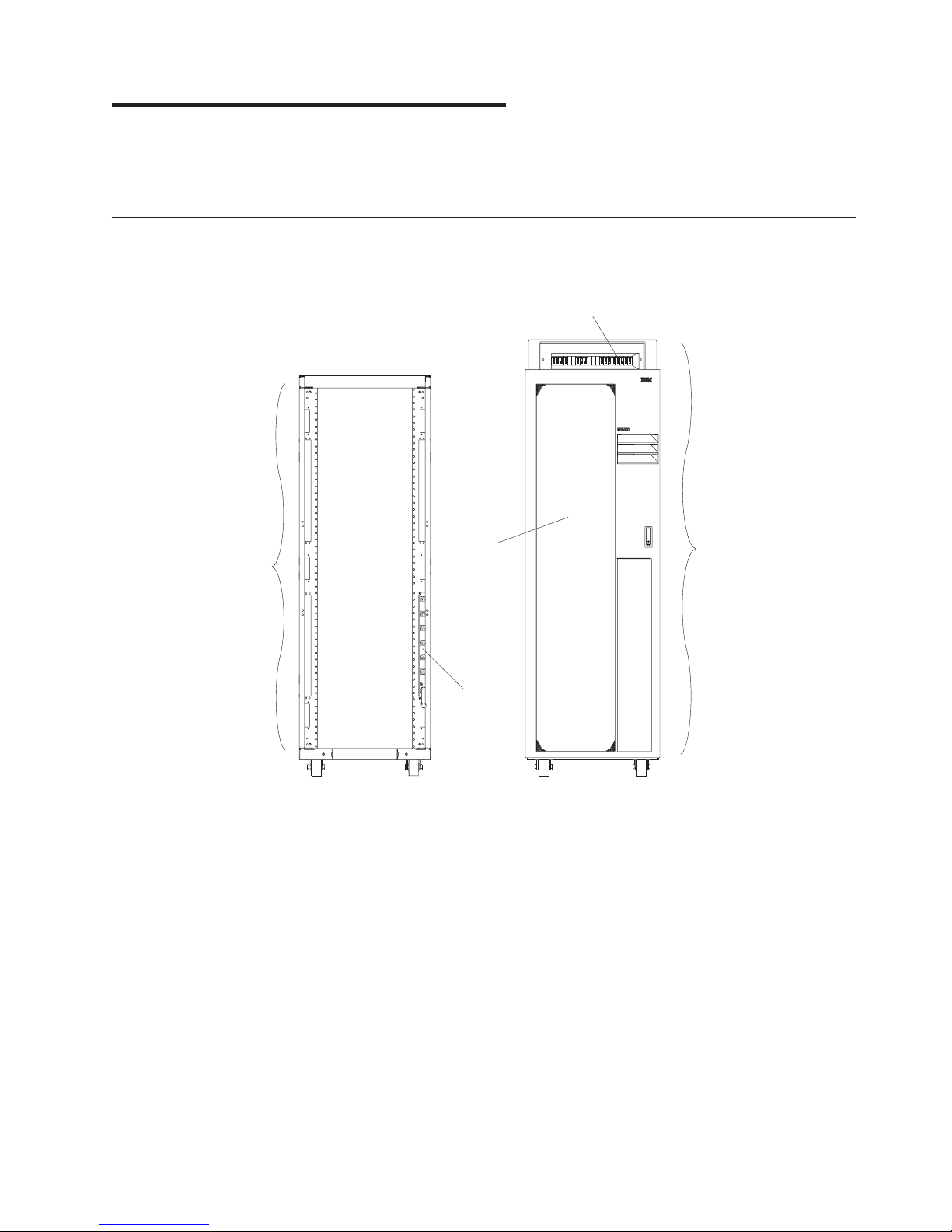
Types of Power Distribution
Power is distributed to the devices and drawers in the rack by ac power distribution buses or by a dc
power distribution panel (Model T00 only).
1
5
Power Distribution Panel
Front View of dc Rack
Optional Front Door (Shown for
reference only)
3
2
4
Power Distribution Bus
Rear View of ac Rack
1
Page 14

v
v
to
v
2
AC Rack Information
This section contains information about ac rack components.
AC Power Distribution Bus
There are two types of ac power distribution buses:
Type 6 power distribution buses have six IEC320-C13, 200 V to 240 V ac outlets. An additional two
front outlets have limited access, as shown in the figures on the following pages. The input ac power to
the bus is not switched, so each outlet has a separate circuit breaker to protect against excessive
current (see the schematic on the following pages). The type 6 power distribution bus feature codes are
9171, 9173, 9174, and 6xxx
Type 7 power distribution buses have nine IEC320-C13, 200 V to 240 V ac outlets. The input ac power
the bus is not switched, so each group of three IEC320-C13, 200 V to 240 V ac outlets has a
separate circuit breaker to protect against excessive current (see the schematic on the following pages).
The type 7 power distribution bus feature codes are 9176, 9177, 9178, and 7xxx.
9188/7188 power distribution buses have twelve IEC320-C13, 200 V to 240 V ac outlets. The input ac
power to the bus is not switched, so each group of two IEC320-C13, 200 V to 240 V ac outlets has a
separate circuit breaker to protect against excessive current (See the schematic on the following
pages.).
rack can contain up to four vertically mounted ac power distribution buses. Two additional power
A
distribution buses (each consuming 1 EIA location) can be mounted horizontally in the bottom rear of a
Model T00 rack, and three additional power distribution buses (each consuming 1 EIA location) can be
mounted horizontally in the bottom rear of a Model T42 rack. The four vertical mounting slots will be filled
first before consuming EIA locations in the rack. Type 6 ac power distribution buses contain eight 200 V to
240 V ac outlets to provide power to the devices and drawers. For type 6, the input ac power to the bus is
not switched, so each outlet has a separate circuit breaker to protect against excessive current.
7014 Model T00, and Model T42 Service Guide
Page 15
1
5
of
2
6
3
7
4
8
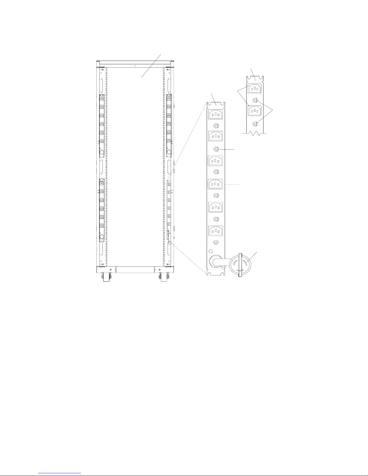
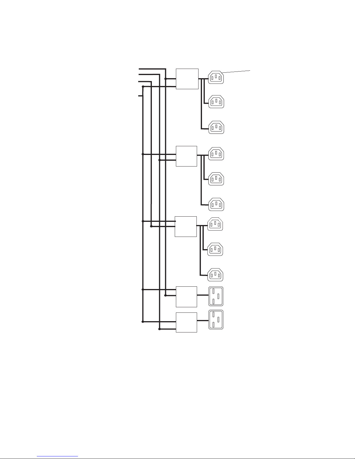
The following illustration shows the type 6 power distribution bus.
1
3
2
4
R7
CB7
5
R6
CB6
L1
L1
R5
CB5
R4
CB4
R8
CB8
6
7
R3
CB3
R2
CB2
L1
R1
CB1
L1
8
Rear View of the Rack
Reset Buttons (Two Facing the Front
the Rack)
Power Distribution Bus
View of the Power Distribution Bus
Reset Buttons
Outlet for Drawers
(Facing the Rack)
Outlets for Peripherals (Two Facing
the Front of the Rack)
Power Cord (Plug Configuration May
Var y)
Note: Circuit breakers for Type 7 buses are on the back of the bus. To access the circuit breaker, remove
the side cover or remove the bus. For information about removing the side cover, refer to ″Step 6.
Installing Multiple Racks″. For information about removing the bus, refer to “Removal and
Replacement of the AC Power Distribution Bus” on page 29.
Chapter 1. Reference Information
3
Page 16
1
6
2
7
3
8
4
9
5
4
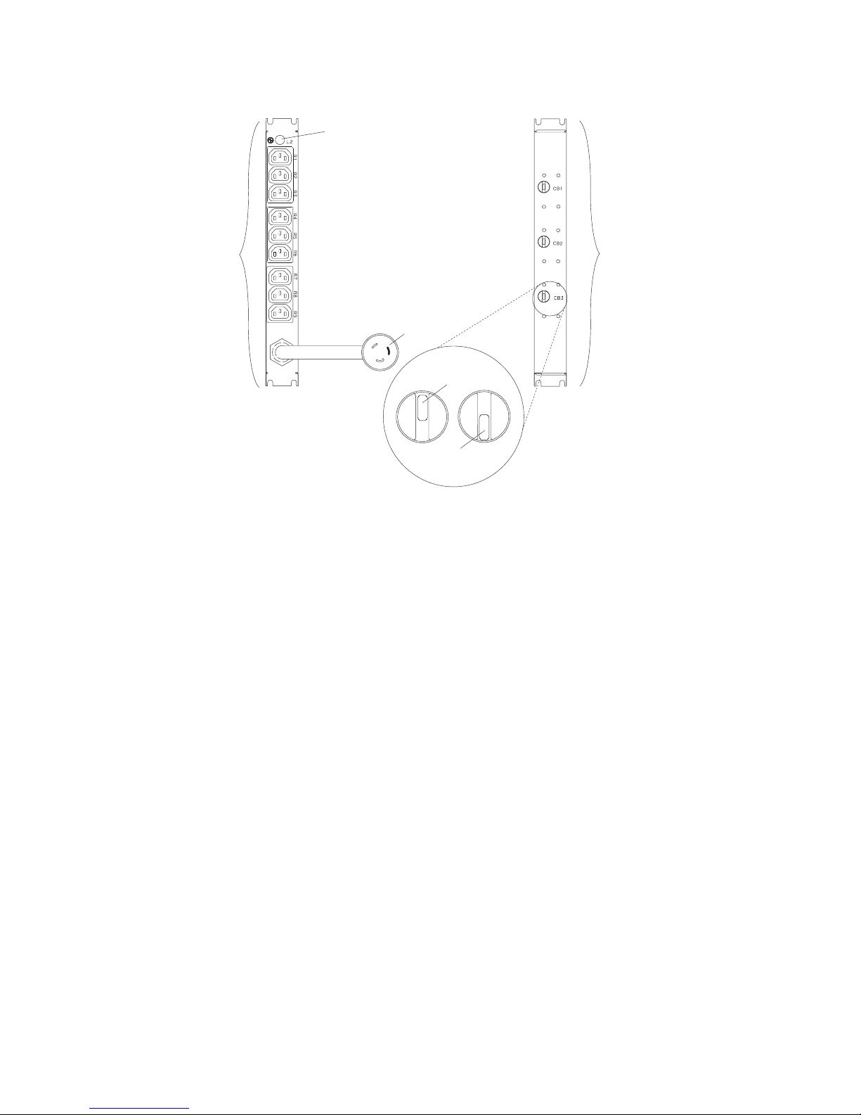
The following illustration shows the type 7 power distribution bus.
7
R1
R2
R3
R4
R5
8
R6
R7
R8
R9
4
5
Off
1
2
9
3
Circuit Breaker 1
Circuit Breaker 2
Circuit Breaker 3
Power Cord (Plug Configuration May
Var y)
Circuit Breaker in Normal Operating
Position
6
Circuit Breaker in Tripped Position
Circuit Breaker Status Lamp
Front of Power Distribution Bus
Rear of Power Distribution Bus
7014 Model T00, and Model T42 Service Guide
Page 17
1a
7a
2a
8a
3a
9 AC
4a
10 AC
5a
11
6a
12 AC
For type 6 buses, the ac power is not switched prior to the individual power outlet circuit breakers.
9
12
1a
2a
3a
4a
5a
6a
1
2
3
10
4
5
6
Reset Circuit Breaker 1
Reset Circuit Breaker 2
Reset Circuit Breaker 3
Reset Circuit Breaker 4
Reset Circuit Breaker 5
Reset Circuit Breaker 6
7a
7
11
8
8a
Reset Circuit Breaker 7
Reset Circuit Breaker 8
Outlets
Outlets Used to Power on
Drawers
Spare Connectors Oulets for
Peripherals (Two Facing Front of
Rack)
Power Plug
Chapter 1. Reference Information
5
Page 18

1a
4 AC
2a
5 AC
3a
6
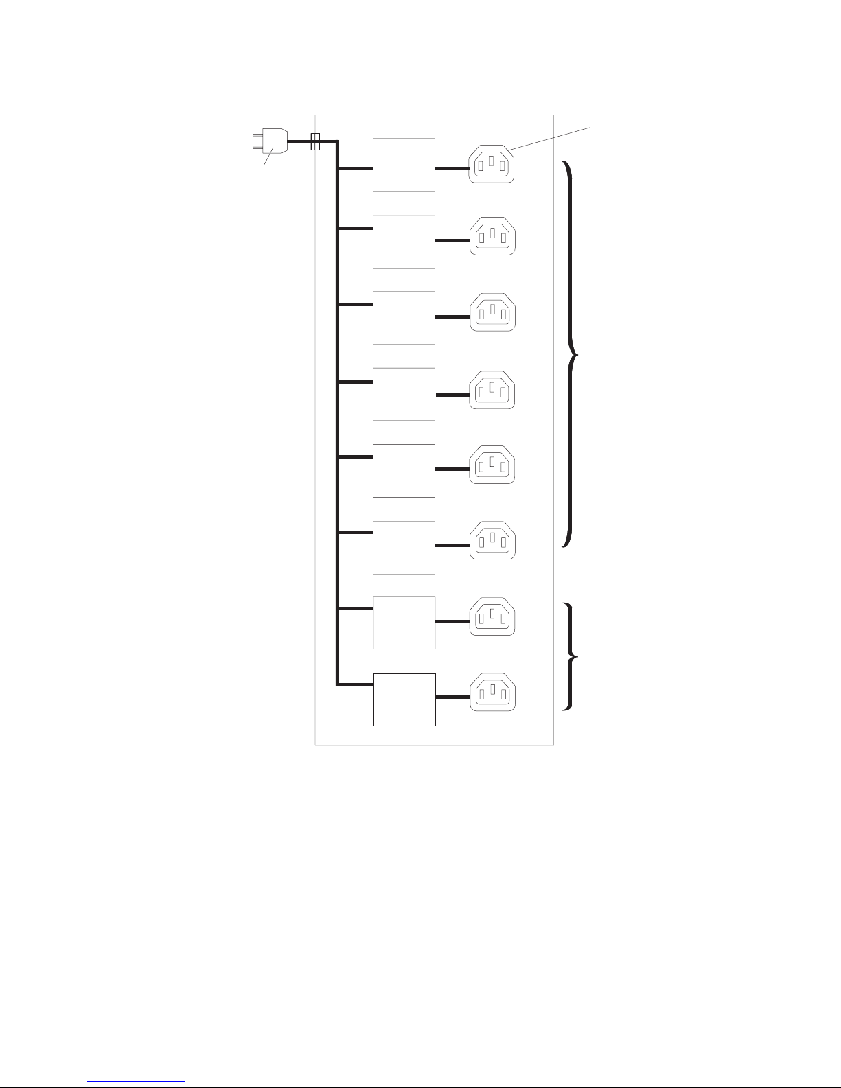
The following illustration shows the type 7 single phase power distribution bus.
4
1a
5
R1
R2
R3
Circuit Breaker 1 (15 Amp)
Circuit Breaker 2 (15 Amp)
Circuit Breaker 3 (15 Amp)
3a
2a
R4
R5
R6
R7
R8
R9
Power Input
Outlets (quantity 9)
Note: The maximum total amperes is 24 amps.
7014 Model T00, and Model T42 Service Guide
Page 19
1a
6 AC
2a
7 AC
3a
8 AC
4a
9
5a
10 AC
The following illustration shows the type 7 three phase power distribution bus.
Type 7 Three Phase Power Distribution Bus
AC
Power
Input
Phase 1
Phase 2
Phase 3
Neutral
Circuit
Breaker 1
20A
Circuit
Breaker 2
20A
Circuit
Breaker 3
20A
AC
Outlets (11)
R1
R2
R3
R4
R5
R6
R7
Circuit Breaker 1 (20 Amp)
Circuit Breaker 2 (20 Amp)
Circuit Breaker 3 (20 Amp)
Circuit Breaker 4 (20 Amp)
Circuit Breaker 5 (20 Amp)
Circuit
Breaker 4
20A
Circuit
Breaker 5
20A
R8
R9
R10
R11
Power Input (Phase 1)
Power Input (Phase 2)
Power Input (Phase 3)
Neutral Line
Outlets (quantity 11)
Chapter 1. Reference Information
7
Page 20
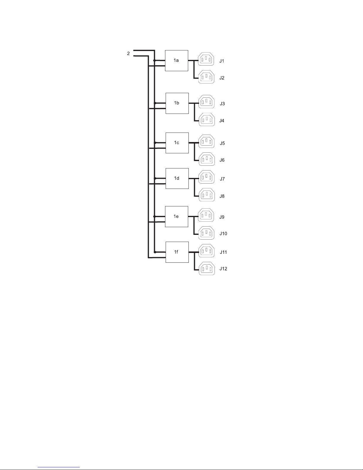
1a
1f
1b
2 AC
1c
1d
1e
8
The following illustration shows the 9188/7188 power distribution bus.
Circuit Breaker 1 (20 Amp)
Circuit Breaker 2 (20 Amp)
Circuit Breaker 3 (20 Amp)
Circuit Breaker 4 (20 Amp)
Circuit Breaker 5 (20 Amp)
7014 Model T00, and Model T42 Service Guide
Circuit Breaker 6 (20 Amp)
Power Input
J1–J12 AC Outlets
Page 21
To
v
v
UL
v
An
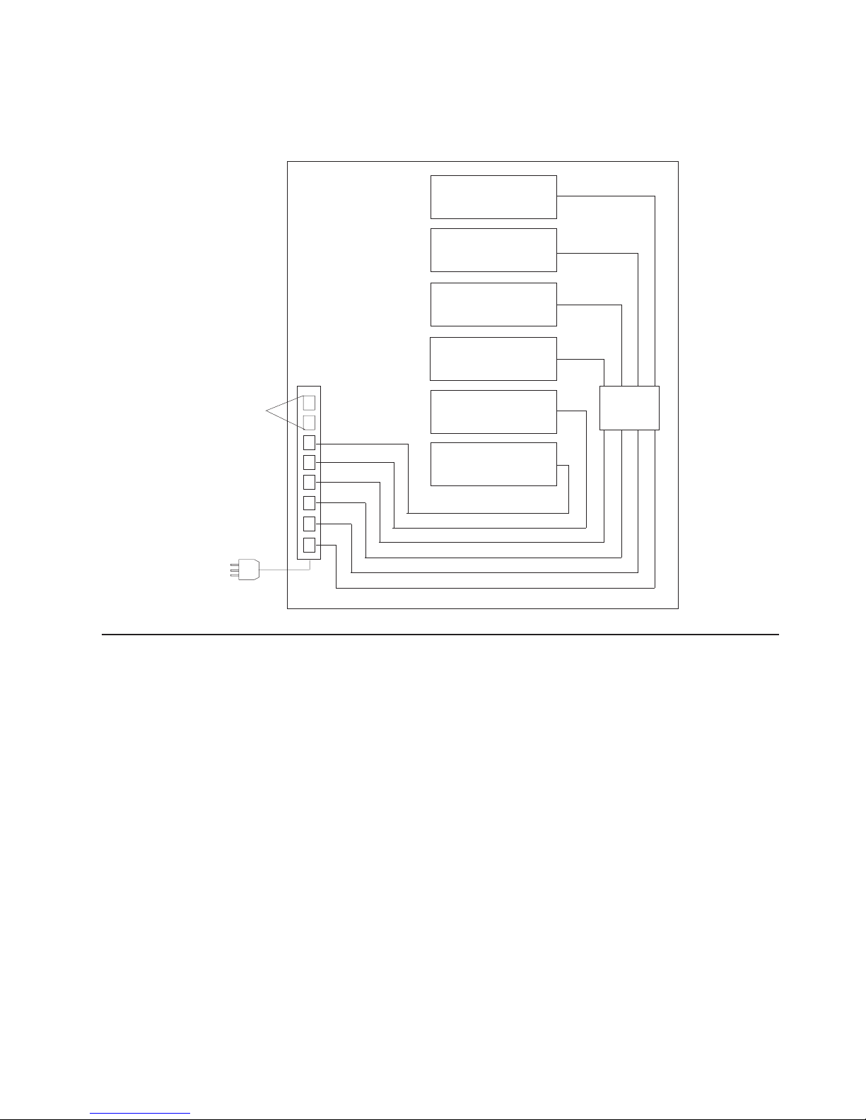
AC Power Distribution Bus Illustration
When the drawer power cords are plugged into the outlets, there should be less than 1 ohm resistance
between the drawer frames or the rack frame.
Outlets for
Peripherals
(Two Facing
Front of Rack)
Power
Distribution
Bus
Main
CPU
Disk Drive
Drawer
Optional Drawer
Disk Drive
Drawer
Optional Drawer
Optional Drawer
Main
Main
Drawer
Power
Cords
External AC Power Cables
avoid electrical shock, the manufacturer provides a power cable with a grounded attachment plug. Use
only properly grounded outlets.
Power cables used in the United States and Canada are listed by Underwriter’s Laboratories (UL) and
certified by the Canadian Standards Association (CSA). These power cords consist of the following:
Electrical cables, type ST
Attachment plugs complying with National Electrical Manufacturers Association (NEMA) as well as other
recognized or UL-listed electrical suppliers.
Appliance couplers complying with IEC Standard 320, Sheets C13, C14 and IEC Standard 309.
find the power cables that are available for the ac rack, refer to “Power Cords” on page 55.
To
Uninterruptible Power Source
uninterruptible power source (UPS) can be installed in the rack that contains an ac power distribution
bus. The uninterruptible power source powers one drawer or device. The uninterruptible power source
contains a power plug (input) and one power outlet (output). IBM offers several UPSs as type 9910 in the
pSeries configurator.
Chapter 1. Reference Information
9
Page 22
A dc
to
1
6
2
7
3
8
4
9
5
10
DC Rack Information
This section contains information about dc rack components.
DC Power Distribution Panel
power distribution panel can be installed on the top of the rack to distribute -48 V dc power to the
drawers and devices in the rack. The dc power distribution panel provides separate circuit breakers to
protect each drawer in the rack from excess current.
The dc power distribution panel configurations shown in this book are for example purposes only. The
actual dc power distribution panel installed in your rack may vary in terms of circuit breaker ratings,
configurations, and connections to the customer’s dc power source.
The power distribution panel contains a connection on the rear of the panel for attaching a
customer-supplied power alarm. This alarm is activated when any circuit breaker is tripped or is switched
the off position.
The circuit breaker is a single pole, single toggle handle unit with stud terminals, UL, CSA and VDE
approved, black with ″on″ and ″off″ markings, and dc with long trip delay. It is on when the handle is up,
and it is off when the handle is down.
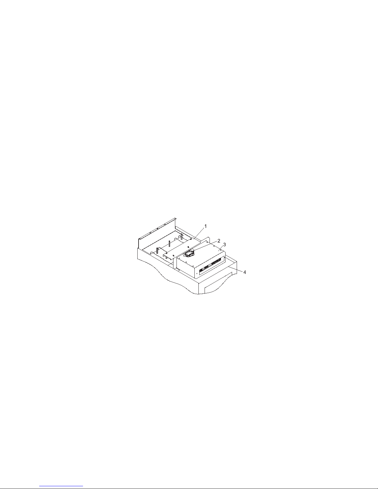
The following illustration shows a typical dc power distribution panel (internal view).
1
2
3
4
9
8
5
7
Mounting Screws
To p Cover
Bus Bar Shield (Insulation)
Terminal Block (Both Sides of the
Rear Cover)
Covers for Empty Circuit Breaker
Positions
6
Front Bezel
Bezel Mounting Screws
Circuit Breaker Switches
Circuit Breaker Position Labels
7014 Model T00, and Model T42 Service Guide
Page 23
be
or to
1
3
2
4
DC Rack Configuration
The dc rack must be connected to an external -48 V dc power source. The -48 V dc power source must
electrically isolated from the ac power source. In addition, the -48 V dc source must be grounded.
The dc rack can be connected to one or two -48 V dc power source to provide redundant power backup. If
two power sources are used, one power source is connected to bus bar A and the other to bus bar B.
The circuit breakers in the dc power distribution panel are attached to two dc power bus bars (bus bar A,
and bus bar B). As described above, these bus bars can be connected either to a common power source
separate power sources (redundant power). Typically, a dc power distribution panel contains two
matching banks of circuit breakers. Each bank of circuit breakers is connected to either bus bar A or bus
bar B. The -48 V dc power supply of each drawer is connected to one circuit breaker in each bank of the
-48 V dc power distribution panel. Thus, when one of the -48 V dc power sources fails, the devices in the
rack still receive power from the other source.
The exact configuration of the dc power distribution panel depends on the configuration of drawers and
devices installed in the rack. Illustrations on the following pages show typical examples of power
distribution for a standalone rack containing a CPU drawer and device drawers.
Note: Before you service the dc power distribution panel, use care to first determine the exact power
configuration and distribution.
The following illustration shows a typical dc power distribution panel (external view).
Cable Channel Cover
Terminal Block (Both Sides)
Power Distribution Panel
Front of Rack
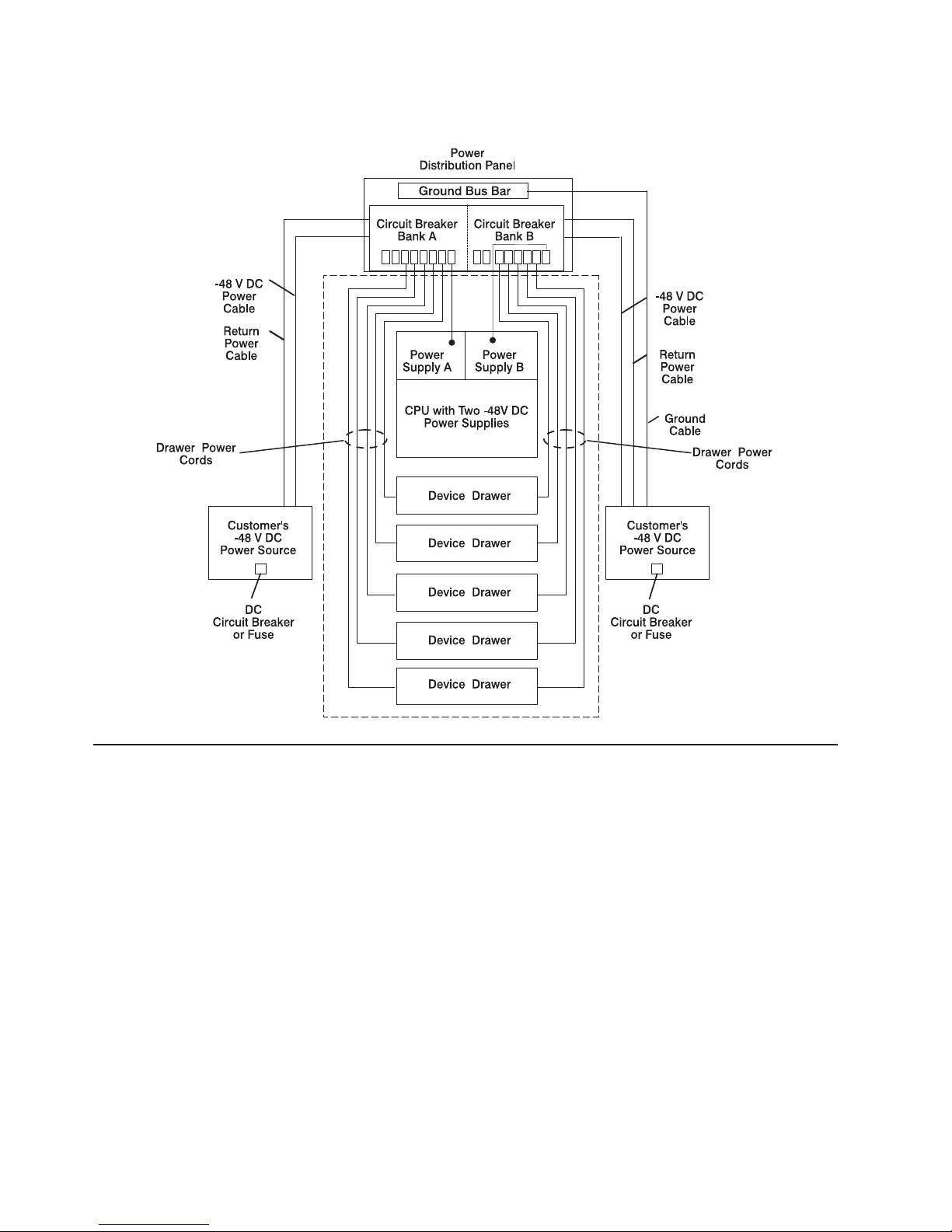
DC Power Distribution and Ground Illustration
The following illustration is for reference only and shows the power distribution in a typical -48 V dc rack
connected to two -48 V dc power sources. Each power supply in the CPU drawer is connected to a
separate circuit breaker in the -48 V dc power distribution panel.
Chapter 1. Reference Information
11
Page 24
v
v
12
When the drawer power cords are connected to the dc power distribution panel, make sure there is less
than 1 ohm resistance between the drawer frames or the rack frame.
DC Rack Power Cables
The customer provides the power cables from the -48 V dc power source to the dc power distribution
panel. The -48 V dc rack must be connected to a -48 V dc power source that is electrically isolated from
the ac power source. In addition, the -48 V dc power source must be reliably grounded.
The -48 V dc rack may be connected to two separate -48 V dc power sources. When the rack is
connected to two power sources, both power sources must be reliably grounded.
Power cables used in the United States and Canada are listed by Underwriter’s Laboratories (UL) and
certified by the Canadian Standards Association (CSA). These power cables have the following
characteristics:
Power cables and ground cables must be a minimum of 6 AWG stranded copper (or equivalent) for
lengths up to 50 feet from the power source.
All connectors must be the copper crimp type (compression). Connector metal must be compatible with
the cable metal.
7014 Model T00, and Model T42 Service Guide
Page 25

v
v
v
v
–
–
–
–
–
–
–
v
v
v
v
v
In
In
Specifications for 7014 Series Model T00 and Model T42 System Rack
Racks
This section contains specifications for the 7014 Series Model T00 and Model T42 System Rack racks.
Dimensions
T00 Height: 1804 mm (71 in)
T00 Height with power distribution panel: 1926 mm (75.8 in)
T42 Height: 2015 mm (79.3 in)
Depth:
T00 and T42 with Rear Door only: 1042 mm (41 in)
T00 with Rear and Front Door: 1098 mm (43.3 in) - Feature 6097 and Feature 6068
T00 with Rear and Front Door: 1147 mm (45.2 in) - Feature 6088
T42 with Rear and Front Door: 1098 mm (43.3 in) - Feature 6083
T42 with Rear and Front Door: 1147 mm (45.2 in) - Feature 6089 and Feature 6069
Width:
v
T00 and T42 without side panels: 623 mm (24.5 in)
T00 and T42 with side panels: 644 mm (25.4 in)
T00 EIA units: 36 EIA units
v
T42 EIA units: 42 EIA units
Weight
T00 Base Empty Rack: 244 kg (535 pounds)
T00 Full Rack: 816 kg (1795 pounds)
T42 Base Empty Rack: 261 kg (575 pounds)
T42 Full Rack: 930 kg (2045 pounds)
Installation Airflow
Rack airflow requirements are a function of the number and type of drawers installed. All rack installations
require careful site and facilities planning designed to address the cumulative drawer heat output and
provide the airflow volume rates necessary to comply with drawer temperature requirements. Refer to the
individual drawer specifications.
Power Requirements
the U.S., each power distribution bus installed in a rack requires a dedicated power line of 200 to 240 V
ac, 30 A.
other countries, input power to each power distribution bus may vary depending upon country
requirements.
Chapter 1. Reference Information
13
Page 26
v
v
v An
v
v
Do
1. If
a.
b.
1
7
2
8
3
9
4
10
5
11
6
12
14
Service Inspection Guide
Perform a service inspection on the rack when any of the following conditions occur:
The rack is inspected under a maintenance agreement.
Service is requested and service has not recently been performed.
alterations-and-attachments review is performed.
Changes have been made to the equipment that might affect the safe operation of the equipment.
External devices with an attached power cord are connected to the rack.
If the inspection indicates an unacceptable safety condition, the condition must be corrected before
representatives service the machine.
Note: The correction of any unsafe condition is the responsibility of the owner of the system.
the following checks:
the rack is bolted down, do the following:
Ensure that the rack is firmly secured to the floor.
Ensure that the four plastic isolator bushings are under the four leveling feet (dc only).
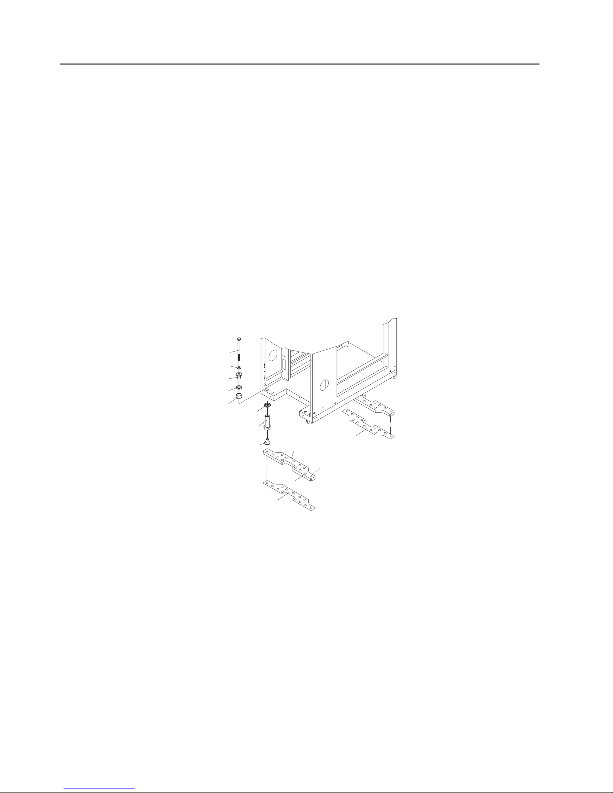
1
2
3
4
5
Rack-Mounting Bolt
Thin Washer
To p Plastic Isolator Bushing
Thick Washer
Spacer
Jam Nut
6
7
8
9
9
10
11
12
Leveling Foot
Lower Plastic Isolator Bushing (Used
only on dc powered systems)
Mounting Plate
Threaded Hole (Used to secure the
rack to mounting plate.)
Anchor Bolt Hole
Traced Pattern (Pattern to be traced
onto the floor using the mounting
plate as a template)
7014 Model T00, and Model T42 Service Guide
Page 27

If
or
1
5
2
6
3
7
4
3.
4.
5.
6.
7.
8.
9.
If
or
2.
the rack is not bolted down, ensure that the stabilizers are firmly attached to both the bottom front
and bottom rear of the rack.
CAUTION:
The stabilizer must be firmly attached to the bottom front of the rack to prevent the rack from
turning over when the drawers are pulled out of the rack. Do not pull out or install any drawer
feature if the stabilizer is not attached to the rack.
C16
1
3
2
Front of Rack
Stabilizer Bar Mounting Screws
Allen Wrench
4
2
3
Stabilizer Bar
Stabilizer Bar Mounting Screws
Mounting Holes
Rear of Rack
Check the covers for sharp edges and for damages or alterations that expose the internal parts of the
rack.
Check the covers for a proper fit to the rack. The covers should be in place and secure.
Open the back door of the rack.
Perform the power-off procedure for the power distribution system installed in your rack. See
″Power-Off Procedure with the AC Power Distribution Bus″ for ac power. See ″Power-Off Procedure
with the DC Power Distribution Panel″ for dc power.
Check for alterations or attachments. If there are any, check for obvious safety hazards such as
broken wires, sharp edges, or broken insulation.
Check the internal cables for damage.
Check for dirt, water, and any other contamination within the rack.
10.
Check the voltage label on the back of the system unit to ensure that it matches the voltage at the
outlet.
11.
Check the external power cable for damage.
12.
your rack is a dc rack, connect the customer’s ground cable to the rack unit and check for 0.1 ohm
less resistance between the metal rack frame and the copper ground strip on the back of the rack.
Chapter 1. Reference Information
15
Page 28

If
a.
1
2
b.
c.
v
v
v
16
13.
your rack is an ac rack, do the following:
With the external power cable connected to the system unit, check for 0.1 ohm or less resistance
between the ground lug on the external power cable plug and the metal frame.
1
L1
2
L1
L1
Rear View of Rack
Ohm Meter
Using the appropriate probe, check for 0.1 ohm or less resistance between the metal frame and
the grounding pin on each of the power outlets on the power distribution bus (check each bus if
there are multiple buses).
Check for the following conditions for each external device that has an attached power cord:
Damage to the power cord.
The correct grounded power cord.
With the external power cord connected to the device, check for 0.1 ohm or less resistance
between the ground lug on the external power cord plug and the metal frame of the device.
14.
Close the rear cover of the rack.
15.
Perform the power-on procedure for the power distribution system installed in your rack. See
“Power-On Procedure with the AC Power Distribution Bus” on page 25 and “Power-On Procedure
with the DC Power Distribution Panel” on page 27.
7014 Model T00, and Model T42 Service Guide
Page 29

If
If
-
Do
NO Go to
Chapter 2. Maintenance Analysis Procedures (MAPs)
This chapter provides diagnostic steps for detecting power problems in the rack. Use these power MAPs
only if you are directed here from a MAP step in the Diagnostic Information for Multiple Bus Systems.
your rack has a power distribution panel, follow the instructions for “MAP 1520: DC Power Distribution
Panel - Power MAP.”
your rack has a power distribution bus, follow the instructions for “MAP 1522: AC Power Distribution Bus
Power MAP” on page 21.
MAP 1520: DC Power Distribution Panel - Power MAP
Purpose of This MAP
This procedure is used to locate power problems in the dc power distribution panel. If a problem is
detected, this procedure helps you isolate the failing field replaceable unit (FRU).
Safety Notices
Observe the following safety notices during service procedures.
DANGER
electrical outlet that is not correctly wired could place hazardous voltage on metal parts of
An
the system or the devices that attach to the system. It is the responsibility of the customer to
ensure that the outlet is correctly wired and grounded to prevent an electrical shock.
Before installing or removing signal cables, ensure that the power cables for the system unit
and all attached devices are unplugged.
When adding or removing any additional devices to or from the system, ensure that the power
cables for those devices are unplugged before the signal cables are connected. If possible,
disconnect all power cables from the existing system before you add a device.
Use one hand, when possible, to connect or disconnect signal cables to prevent a possible
shock from touching two surfaces with different electrical potentials.
During an electrical storm, do not connect cables for display stations, printers, telephones, or
station protectors for communications lines.
D05
CAUTION:
Energy hazard, remove power before servicing. Disconnect two power supply cords.
C23
Step 1520-1
any of the devices in the rack have their power indicator(s) lit? (front operator panel or power
supply LED).
“Step 1520-10” on page 19.
YES Go to “Step 1520-2” on page 18.
17
Page 30

Is
NO Go to
Is
NO
Is
NO Go to
1.
2.
3.
Is
NO
to
NO Go to
Is
NO
18
Step 1520-2
Check the circuit breaker for the drawer that does not have power.
the circuit breaker tripped?
“Step 1520-7.”
YES Reset the circuit breaker by turning the circuit breaker off, then on. Go to “Step 1520-3.”
Step 1520-3
there power to the drawer?
Check the circuit breaker again. Go to “Step 1520-4.”
YES Go to ″MAP 0410: Repair Checkout″ in the Diagnostic Information for Multiple Bus Systems.
Step 1520-4
the circuit breaker tripped again?
“Step 1520-7.”
YES Go to “Step 1520-5.”
Step 1520-5
Set the circuit breaker to the off position.
Disconnect the power cable from the device’s power supply.
Set the circuit breaker to the on position.
the circuit breaker tripped again?
Replace the device power supply. Go to ″MAP 0410: Repair Checkout″ in the Diagnostic
Information for Multiple Bus Systems.
YES Turn circuit breaker off and replace the power cable. Set the circuit breaker to the on position. Go
“Step 1520-6.”
Step 1520-6
Did the circuit breaker trip again?
″MAP 0410: Repair Checkout″ in the Diagnostic Information for Multiple Bus Systems.
YES Replace the circuit breaker. Go to ″MAP 0410: Repair Checkout″ in the Diagnostic Information for
Multiple Bus Systems.
Step 1520-7
there power to the drawer?
Replace the device power supply. Go to “Step 1520-8” on page 19.
YES Go to ″MAP 0410: Repair Checkout″ in the Diagnostic Information for Multiple Bus Systems.
CAUTION:
Energy hazard, remove power before servicing. Disconnect two power supply cords.
C23
7014 Model T00, and Model T42 Service Guide
Page 31

Is
NO Go to
Is
NO Go to
NO
1.
2.
3.
Is
NO Go to
1.
2.
3.
4.
NO
Step 1520-8
there power to the drawer?
“Step 1520-9.”
YES Go to ″MAP 0410: Repair Checkout″ in the Diagnostic Information for Multiple Bus Systems.
Step 1520-9
Set the circuit breaker to the off position, and replace the power cable between the circuit breaker and the
device.
there power to the drawer?
“Step 1520-14” on page 20.
YES Go to ″MAP 0410: Repair Checkout″ in the Diagnostic Information for Multiple Bus Systems.
Step 1520-10
Are all the circuit breakers turned on?
Turn the circuit breakers on. Then go to ″MAP 0410: Repair Checkout″ in the Diagnostic
Information for Multiple Bus Systems.
YES Go to “Step 1520-11.”
Step 1520-11
Set all of the circuit breaker switches to the off position (switches in the down position).
Locate terminal board 2 (TB2) on the outside of the rear cover of the power distribution panel.
Measure for -40 to -60 V dc on terminal board 2 (TB2) between positions one and two (side A circuit
breaker) and between positions five and six (side B circuit breaker).
the voltage between -40 and -60 V dc?
“Step 1520-12.”
YES Go to “Step 1520-13” on page 20.
Step 1520-12
Remove the six screws attaching the top cover of the power distribution panel.
Remove the top cover and then remove the insulator.
Using a multimeter, attach the black multimeter cable lead to the return bus bar (+), and then attach
the red multimeter cable lead to the -48 V dc bus bar (-).
Measure for -40 to -60 V dc between the -48 V dc bus bar (upper bar) and the return bus bar (lower
bar) in the power distribution panel.
Was the correct voltage present?
Ask the customer to check the power source for the correct voltage, and check the external power
cable (from customer’s power source) for continuity.
YES Go to “Step 1520-13” on page 20.
Chapter 2. Maintenance Analysis Procedures
19
Page 32

Do
NO Go to
1.
2.
3.
Is
NO
NO
20
Step 1520-13
Set all of the circuit breaker switches on the power distribution panel to the on position.
all the power supplies on the devices have power?
“Step 1520-14.”
YES Go to ″MAP 0410: Repair Checkout″ in the Diagnostic Information for Multiple Bus Systems.
Step 1520-14
Ensure that the circuit breaker is in the on position.
Using a multimeter, attach the black multimeter cable lead to the return bus bar (+), and then attach
the red multimeter cable lead to the bottom terminal on the circuit breaker.
Measure for -40 to -60 V dc between the -48 V dc circuit breaker and the return bus bar (lower bar) in
the power distribution panel.
the voltage between -40 and -60 V dc?
Replace the circuit breaker. Then go to ″MAP 0410: Repair Checkout″ in the Diagnostic
Information for Multiple Bus Systems.
YES Go to “Step 1520-15.”
Step 1520-15
Has the device power supply previously been replaced?
Replace the power supply. Then go to ″MAP 0410: Repair Checkout″ in the Diagnostic Information
for Multiple Bus Systems.
YES Replace the cable. Then go to ″MAP 0410: Repair Checkout″ in the Diagnostic Information for
Multiple Bus Systems.
7014 Model T00, and Model T42 Service Guide
Page 33

If
to
Is
NO Go to
MAP 1522: AC Power Distribution Bus - Power MAP
Purpose of This MAP
This procedure is used to locate power problems in the power distribution bus. If a problem is detected,
this procedure will help you isolate the failing field replaceable unit (FRU).
the rack contains more than one power distribution bus, use this MAP to test the power distribution bus
that is connected to the failing drawer. If you cannot determine which power distribution bus is connected
the failing drawer, use this MAP to test the first power distribution bus, and then test the other power
distribution bus until the problem is determined.
Safety Notices
Observe the following safety notices during service procedures.
DANGER
electrical outlet that is not correctly wired could place hazardous voltage on metal parts of
An
the system or the devices that attach to the system. It is the responsibility of the customer to
ensure that the outlet is correctly wired and grounded to prevent an electrical shock.
Before installing or removing signal cables, ensure that the power cables for the system unit
and all attached devices are unplugged.
When adding or removing any additional devices to or from the system, ensure that the power
cables for those devices are unplugged before the signal cables are connected. If possible,
disconnect all power cables from the existing system before you add a device.
Use one hand, when possible, to connect or disconnect signal cables to prevent a possible
shock from touching two surfaces with different electrical potentials.
During an electrical storm, do not connect cables for display stations, printers, telephones, or
station protectors for communications lines.
D05
Step 1522-1
uninterruptible power source installed?
“Step 1522-4” on page 22.
YES Go to “Step 1522-2” on page 22.
Chapter 2. Maintenance Analysis Procedures
21
Page 34

If
NO
NO
to
NO If
NO
go to
NO Go to
22
Step 1522-2
the system is not receiving power and the LED on the power distribution bus is off, unplug the
customer’s power cable from the uninterruptible power source, and then plug the customer’s power cable
into the power distribution bus.
The green LEDs located on the power distribution bus indicate that power is supplied from the customer’s
outlet, through the customer’s power cable, and to the power distribution bus.
Are the LEDs on the power distribution bus ON?
Check the customer’s power cable for the proper voltage from the wall outlet to the power
distribution bus or uninterruptible power source. Then go to “Step 1522-3.”
YES Replace the uninterruptible power source if necessary. Refer to the maintenance and diagnostic
information in the service guide for the uninterruptible power source installed in your rack, and
then go to “Step 1522-10” on page 23.
Step 1522-3
Was the voltage correct?
Check the customer’s outlet for the correct voltage. If correct, exchange the power cable. Then go
“Step 1522-10” on page 23.
YES Exchange the power distribution bus, and go to “Step 1522-10” on page 23.
Step 1522-4
Did any of the power lights on the devices come on and stay on?
the LED on the power distribution panel is off, check the customer’s power cable for the proper
voltage from the wall outlet to the power distribution bus and go to “Step 1522-5.”
YES If a single device is not receiving power, go to “Step 1522-6.”
Step 1522-5
Was the voltage correct?
Check the customer’s outlet for the correct voltage. If correct, exchange the power cable and then
“Step 1522-10” on page 23.
YES Exchange the power distribution bus and go to “Step 1522-10” on page 23.
Step 1522-6
Did the drawer power reset circuit breaker on the power distribution bus go to the Off position
(pop out)?
“Step 1522-7” on page 23.
YES Go to “Step 1522-9” on page 23.
7014 Model T00, and Model T42 Service Guide
Page 35

1.
2.
NO Go to
1.
2.
NO
1.
2.
NO
1.
2.
Step 1522-7
Plug the drawer power cable into another outlet on the power distribution bus.
Turn on power to the drawer.
Did the drawer power light come on and stay on?
“Step 1522-8.”
YES The first outlet is defective. Use the second outlet, or exchange the power distribution bus, and
then go to “Step 1522-10.”
Step 1522-8
Plug the power cable of another device or drawer into the same outlet.
Turn on power to the device or drawer.
The green light near the ac plug on the rear of some drawers indicates only that power is reaching the
drawer and not that the power supply is operating.
Did the drawer power light come on and stay on or are the fans operating?
Exchange the power distribution bus, and then go to “Step 1522-10.”
YES The problem is probably located in the original drawer. Go to “MAP 1520: DC Power Distribution
Panel - Power MAP” on page 17 in the service guide for the system installed in your rack.
Step 1522-9
Plug the CPU drawer power cable into another outlet on the power distribution bus.
Set the power button to on (button pushed in).
Did the circuit breaker go to the Off position (pop out)?
The first circuit breaker is probably defective. Use the second outlet, or exchange the power
distribution bus, and then go to “Step 1522-10.”
YES The drawer is overloading the circuit breaker. Exchange the CPU drawer power cable or power
supply. Then go to “Step 1522-10.”
Step 1522-10
Connect all drawer power cables to their original power outlets on the power distribution bus.
This completes the repair. Go to ″MAP 0410: Repair Checkout″ in the Diagnostic Information for
Multiple Bus Systems.
Chapter 2. Maintenance Analysis Procedures
23
Page 36

24
7014 Model T00, and Model T42 Service Guide
Page 37

1.
Chapter 3. Removal and Replacement Procedures
This chapter contains information about powering the rack on and off, and removing and replacing
components.
Use the correct power-on and power-off procedure for the type of power distribution used in your rack.
Safety Notices
This section contains safety notices that apply to all the procedures in this chapter. Review this section
carefully before performing any power-related operations.
DANGER
An electrical outlet that is not correctly wired could place hazardous voltage on metal parts of
the system or the devices that attach to the system. It is the responsibility of the customer to
ensure that the outlet is correctly wired and grounded to prevent an electrical shock.
Before installing or removing signal cables, ensure that the power cables for the system unit
and all attached devices are unplugged.
When adding or removing any additional devices to or from the system, ensure that the power
cables for those devices are unplugged before the signal cables are connected. If possible,
disconnect all power cables from the existing system before you add a device.
Use one hand, when possible, to connect or disconnect signal cables to prevent a possible
shock from touching two surfaces with different electrical potentials.
During an electrical storm, do not connect cables for display stations, printers, telephones, or
station protectors for communications lines.
D05
CAUTION:
This unit has more than one power supply cord. To reduce the risk of electrical shock, disconnect
two power supply cords before servicing.
C21
Operating System Shutdown
Before powering off any drawers or external devices, ask the customer if this rack is used in a
high-availability system. If it is, notify the customer that other attached systems might be affected by this
procedure.
Notify the customer if you are going to turn off power to any drawers that are attached to drawers or
devices in another system.
Before powering off the system unit, you must first shut down the operating system to prevent losing data.
Ask the customer to shut down all programs. Failure to do so can result in the loss of data. See your
operating system documentation for information about the shutdown command.
Power-On Procedure with the AC Power Distribution Bus
This section covers the ac rack power-on procedures.
Plug all drawer power cables into the outlets on the ac power distribution bus or buses.
25
Page 38

If
1
5
of
2
6
3
7
4
8
3.
4.
26
2.
more than one ac power distribution bus is installed in the rack, plug the power cable of each into
the customer’s ac power outlet.
CAUTION:
This product is equipped with a three-wire power cable and plug for the user’s safety. Use this
power cable with a properly grounded electrical outlet to avoid electrical shock.
C01
For illustration purposes, the type 6 power distribution bus is shown. However, this procedure also
applies to the type 7 and 9188/7188 power distribution buses.
1
3
2
4
R7
CB7
5
R6
CB6
L1
L1
R5
CB5
R4
CB4
R8
CB8
6
7
R3
CB3
R2
CB2
L1
R1
CB1
L1
8
Rear View of the Rack
Power Distribution Bus
View of the Power Distribution Bus
(Facing the Rack)
Outlets for Peripherals (Two Facing
the Front of the Rack)
Follow the power-on procedures for the drawers installed in the rack. For more information, refer to the
service guide for the drawers installed in the rack.
Close the rear door of the rack.
7014 Model T00, and Model T42 Service Guide
Reset Buttons (Two Facing the Front
the Rack)
Reset Buttons
Outlet for Drawers
Power Cord (Plug Configuration May
Var y)
Page 39

1. Be
2.
3.
If
4.
5.
6.
It is
dc
1.
1
3
2
4
Power-Off Procedure with the AC Power Distribution Bus
This section covers the ac power-off procedure.
sure the operating system is shut down. See “Operating System Shutdown” on page 25.
Power off each of the drawers installed in the rack. For more information, refer to the service guide for
the drawers installed in the rack.
Note: Because many drawers or devices can be connected to the system unit, it may be impractical
for you to switch off power to all the drawers or devices and unplug their power cables.
Open the rear door of the rack.
Note:
more than one ac power distribution bus is installed in your rack and you are servicing only
one, power off the drawers connected to the ac power distribution bus that you are servicing.
Turn off power to all drawers or devices that are connected to the ac power distribution bus that you
are servicing.
Unplug all the drawer or device power cables from the ac power distribution bus that you are servicing.
Unplug the power cable from the customer’s ac power outlet.
Power-On Procedure with the DC Power Distribution Panel
This section covers the power-on procedure for the dc rack.
CAUTION:
Energy hazard, remove power before servicing. Disconnect two power supply cords.
C23
Note:
Locate terminal board 2 (TB2) on the outside of the dc power distribution panel.
the customer’s responsibility to provide and have a qualified technician properly install both the
power source cables from the customer’s -48 V dc power source to the dc power distribution
panel. The customer is also responsible for connecting the customer-supplied ground cable to the
ground bus bar on the rack frame.
Cable Channel Cover
Terminal Block (Both Sides)
Power Distribution Panel
Front of Rack
Chapter 3. Removal and Replacement
27
Page 40

2
2.
a.
b.
c.
1
2
3 Up
3.
4.
5.
6.
28
2
1
3
1
5
4
6
8
7
2
1 Power Status Connections for Side A Circuit Breaker
Power Status Connections for Side B Circuit Breaker
Using a polarity-sensitive multimeter, ensure that the voltage and polarity are correct at the dc power
distribution panel (check both the -48 V dc bus and the -48 V dc return bus) as follows:
Ensure that all circuit breakers are off (circuit breaker switches in the down position).
Measure for -40 V dc to -60 V dc between position 1 (-) and position 2 (+) on terminal board 2 to
test the power for side A.
Measure for -40 V dc to -60 V dc between position 5 (-) and position 6 (+) on terminal board 2 to
test the power for side B.
The following illustration shows the front view of the power distribution panel (PDP)
A1 B1A2 B2A3 B3
A4 B4A5 B5
1
A7
A6 B6
A8 A9
B7
B8 B9
Plug all externally attached device power cords into customer’s the electrical outlets.
Turn on power to all external devices attached to the system unit. For more information, refer to the
service guide.
Set all the circuit breakers to the on position (up).
Turn on power to all of the devices and drawers connected to the dc power distribution panel.
7014 Model T00, and Model T42 Service Guide
2
3
Circuit Breaker Positions (Not labeled on PDP)
Down Position (Off)
Position (On)
Page 41

1. Be
2.
3.
4.
of
5.
1
2
3 Up
Power-Off Procedure with the DC Power Distribution Panel
This section covers the power-off procedure for the dc rack.
sure the operating system is shut down. See “Operating System Shutdown” on page 25.
Turn off power to all devices and drawers in the rack. For more information, refer to the service guide.
Turn off power to all external devices attached to the system.
Unplug the device power cords from the customer’s electrical outlets.
Note: If drawers in attached racks are connected to circuit breakers in the dc power distribution panel
this rack, power to the drawers in attached racks will be powered off if the circuit breakers in
this rack are set to off.
Except for circuit breakers in this rack that are connected to drawers in another rack, set all circuit
breakers to the off position (down).
CAUTION:
Energy hazard, remove power before servicing. Disconnect two power supply cords.
C23
Note: Because a large number of external devices can be connected to the system unit, it might be
impractical for you to turn off power to all the devices and unplug their power cords.
The following illustration shows the front view of the power distribution panel (PDP)
A1 B1A2 B2A3 B3
A4 B4A5 B5
1
2
Circuit Breaker Positions (Not labeled on PDP)
Down Position (Off)
Position (On)
A7
A6 B6
A8 A9
B7
B8 B9
3
Removal and Replacement of the AC Power Distribution Bus
This section covers the removal and replacement procedures for the ac power distribution bus. The
following illustration shows where the ac power distribution bus might be installed.
Note: If there are more than four power distribution buses in the rack, additional buses may be mounted
horizontally in the rear mounting rails of the rack.
Chapter 3. Removal and Replacement
29
Page 42

to
1
5
of
2
6
3
7
4
8
1.
2.
3.
4.
5.
30
For illustration purposes, the type 6 power distribution bus is shown. However, this procedure also applies
the type 7 and 9188/7188 power distribution buses.
1
3
2
4
R7
CB7
5
R6
CB6
L1
L1
R5
CB5
R4
CB4
R8
CB8
6
7
R3
CB3
R2
CB2
L1
R1
CB1
L1
8
Rear View of the Rack
Power Distribution Bus
View of the Power Distribution Bus
(Facing the Rack)
Outlets for Peripherals (Two Facing
the Front of the Rack)
Removal
This section covers the removal procedure of the ac power distribution bus.
Follow the “Power-Off Procedure with the AC Power Distribution Bus” on page 27.
Turn off power and disconnect the ac power distribution bus from the customer’s ac power outlet.
Record the locations of the drawer ac power cables plugged into the ac power distribution bus.
Unplug the drawer ac power cables from the ac power distribution bus.
Remove the four mounting screws from the ac power distribution bus and, pull the bus toward you to
access the power connectors on the other side of the bus.
Unplug the power cables from the other side of the bus. Remove the ac power distribution bus from
the rack.
7014 Model T00, and Model T42 Service Guide
Reset Buttons (Two Facing the Front
the Rack)
Reset Buttons
Outlet for Drawers
Power Cord (Plug Configuration May
Var y)
Page 43

On
1. On
2.
3.
4.
5.
6.
1.
2.
3.
4.
5.
6. If
6.
9188 or 7188 ac power distribution buses only, remove the top and bottom L-bracket on the PDU
via the two screws per bracket.
Replacement
This section covers the replacement for the ac power distribution bus.
9188 or 7188 ac power distribution buses only, install the top and bottom L-bracket on the PDU via
the two screws per bracket.
Reconnect any power cables that you disconnected from the other side of the ac power distribution
bus.
Slide the ac power distribution bus into position, and install the four mounting screws.
Reconnect any power cables that you disconnected from the ac power distribution bus.
Plug the power cables into the locations that you recorded during the removal procedure.
Follow the steps in “Power-On Procedure with the AC Power Distribution Bus” on page 25.
Removal and Replacement of the DC Power Distribution Panel
This section covers the removal and replacement procedure for the dc power distribution panel.
CAUTION:
Energy hazard, remove power before servicing. Disconnect two power supply cords.
C23
Removal
This section covers the removal procedures for the dc power distribution panel.
Follow the steps in “Power-Off Procedure with the DC Power Distribution Panel” on page 29.
Note: Removing power to the dc power distribution panel does not remove power to drawers in this
rack that are powered by the dc power distribution panel in another rack.
Have the customer turn off the dc power source that connects to the dc power distribution panel.
After the customer’s -48 V dc source power is turned off, ensure that a tag or label is positioned over
the power source switches to indicate that the power is intended to be off (lock-out/tag-out).
Remove the six mounting screws from the top cover of the power distribution panel. Then remove the
top cover.
Remove the -48 V dc bus shield (insulation) from the dc power distribution panel.
one is installed, remove the cable channel cover.
Chapter 3. Removal and Replacement
31
Page 44

1
6
2
7
3
8
4
9
5
7.
dc
8.
9.
1
6 B
2 A
7 B
3 A
8 B
4 A
9 B
5 A
32
The following illustration shows a typical dc power distribution panel (internal view).
1
2
3
9
8
5
7
6
4
Mounting Screws
To p Cover
Bus Bar Shield (Insulation)
Terminal Block (Both Sides of the
Front Bezel
Bezel Mounting Screws
Circuit Breaker Switches
Circuit Breaker Position Labels
Rear Cover)
Covers for Empty Circuit Breaker
Positions
With a multimeter, verify that no voltage exists between the two -48 V dc bus bars and the two -48 V
return bus bars.
Ensure that the customer’s service provider completely disconnects the two -48 V dc power source
cables from the -48 V dc bus bars, and the two -48 V dc return ground cables from the -48 V dc
return bus bars.
Record the locations and connection points of all cables.
10.
Disconnect all drawer power cables.
Front of Power Distribution Panel
-48 V dc (-) Bus Bar
-48 V dc (-) Power Cable
Return (-) Bus Bar
Return (-) Power Cable
7014 Model T00, and Model T42 Service Guide
Return (-) Power Cable
-48 V dc (-) Power Cable
Return (-) Bus Bar
-48 V dc (-) Bus Bar
Page 45

1
4
2
5
3
11.
Remove the four mounting screws that attach the dc power distribution panel to the top of the rack,
and remove the panel.
1
2
3
5
Ground Wire with Connector
Mounting Screw (quantity 4)
Power Distribution Panel
4
Ground Wire Connector
Mounting Screw (This screw secures
both the Power Distribution Panel and
the Ground Wire.)
Chapter 3. Removal and Replacement
33
Page 46

1. If it is
2.
3.
4.
5.
6. Be
7.
to
1
6 B
2 A
7 B
3 A
8 B
4 A
9 B
5 A
8.
9.
34
Replacement
This section covers the replacement procedure for the dc power distribution panel.
not already off, remove the top cover of the dc power distribution panel.
Remove the shield.
Place the dc power distribution panel in position on the top of the rack, and install the four mounting
screws.
Route and attach the drawer power cables.
Ensure that all circuit breakers are set to off.
sure that the customer’s dc power source is turned off.
Ensure that the customer’s service provider properly connects the two -48 V dc power source cables
the -48 V dc bus bars, and the two -48 V dc return cables to the -48 V dc return bus bars.
Front of Power Distribution Panel
-48 V dc (-) Bus Bar
-48 V dc (-) Power Cable
Return (-) Bus Bar
Return (-) Power Cable
Replace the -48 V dc bus bar shield (insulation).
Replace the top cover of the dc power distribution panel.
Return (-) Power Cable
-48 V dc (-) Power Cable
Return (-) Bus Bar
-48 V dc (-) Bus Bar
7014 Model T00, and Model T42 Service Guide
Page 47

If
1
4
2
5
3
6
10.
necessary, replace the cable channel cover.
Mounting Screw (quantity 4)
Cable Channel Cover
Mounting Screw (quantity 6)
1
2
3
4
5
6
Shield
Power Distribution Panel (PDP)
Front of Rack
11.
Have the customer turn on the -48 V dc power source.
12.
Follow the steps in “Power-On Procedure with the DC Power Distribution Panel” on page 27.
Chapter 3. Removal and Replacement
35
Page 48

1.
2.
3.
4.
5.
6.
1
6
2
7
3
8
4
9
5
36
Removal and Replacement of the -48 V DC Circuit Breaker
This section covers the removal and replacement procedure for the -48 V dc circuit breaker.
CAUTION:
Energy hazard, remove power before servicing. Disconnect two power supply cords.
C23
Removal
This section covers the removal procedures for the -48 V dc circuit breaker.
Follow the steps in the “Power-Off Procedure with the DC Power Distribution Panel” on page 29.
Have the customer turn off the dc power source that connects to the dc power distribution panel.
After the customer’s -48 V dc source power is turned off, ensure that a tag or label is positioned over
the power source switches to indicate that the power is intended to be off (lock-out/tag-out).
Remove the six mounting screws from the top cover of the power distribution panel, and then remove
the top cover.
Remove the -48 V dc bus shield (insulation).
Remove the bezel from the front of the dc power distribution panel.
1
9
8
5
7
6
Mounting Screws
To p Cover
Bus Bar Shield (Insulation)
Terminal Block (Both Sides of the
Rear Cover)
Covers for Empty Circuit Breaker
Positions
2
3
4
Front Bezel
Bezel Mounting Screws
Circuit Breaker Switches
Circuit Breaker Position Labels
7014 Model T00, and Model T42 Service Guide
Page 49

8.
9.
1 A
8
2 A
9
3 A
10
4 10 mm
11
5 A
12 B
6 B
13 B
7 B
14
7.
Using a multimeter, verify that no voltage exists between the -48 V dc bus bars and the -48 V dc
return bus bars, A and B sides.
Record the locations of all cables or wires connected to the three connector pins on the circuit
breaker that is being removed. Disconnect the wires from the three connector pins and the -48 V dc
power connector.
Disconnect the wire that is attached to the bottom of the circuit breaker.
10.
Disconnect the mounting nut that attaches the rear of the circuit breaker to the dc power bus bar.
13
14
1
2
3
4
12
5
6
7
8
9
-48 V dc (-) Bus Bar
-48 V dc (-) Power Cable
Return (+) Bus Bar
hole, 25.4 mm Spacing
Return (+) Power Cable
Return (+) Power Cable
-48 V dc (-) Power Cable
10
11
Mounting Nut
Three Connector Pins
-48 V dc (-) Power Connector
Connector Nut
Return (+) Bus Bar
-48 V dc (-) Bus Bar
Front of Power Distribution Panel
Chapter 3. Removal and Replacement
37
Page 50

1
2
1.
2.
3.
4.
5.
6.
7.
8.
9. Be
38
11.
Remove the two mounting screws holding the circuit breaker to the panel. Then remove the circuit
breaker from the inside of the panel.
2
1
Front View of Power Distribution Panel (Without Bezel)
Mounting Screws
Note: The PDP shown is for reference only.
Replacement
This section covers the replacement procedures for the -48 V dc circuit breaker.
Mount the circuit breaker to the front of the dc power distribution panel using the two mounting
screws.
Fasten the rear of the circuit breaker to the dc power distribution panel with the mounting nut.
Connect the -48 V dc cable to the circuit breaker using the cable connector nut.
Connect the two wires to the two connector pins on the rear of the circuit breaker.
Replace the front bezel of the dc power distribution panel.
Replace the -48 V dc bus bar shield (insulation).
Replace the top cover of the dc power distribution panel.
Have the customer restore power to the dc power distribution panel.
sure all circuit breakers are set to on.
10.
Follow the steps in “Power-On Procedure with the DC Power Distribution Panel” on page 27.
7014 Model T00, and Model T42 Service Guide
Page 51

It is
1.
2.
1
4
2
5
3
6
3. If
4. If
1.
2.
3.
4.
5.
6.
Removal and Replacement of the Front or Rear Door
possible that inspection or service procedures for certain drawers might require removing the front or
rear door for better access. If this is necessary, follow these instructions.
Removal
This section covers the removal procedure for the front or rear door.
Open the door of the rack.
Remove the door by lifting it up and out.
1
2
6
4
3
5
4
3
Rack Cabinet
Front Rack Door
Door Hinge
Hinge Retaining Screws
Door Latch
Door Latch Mounting Screws
necessary, remove the hinge bracket by removing the mounting screws that attach the bracket to the
rack.
necessary, also remove the latch plate by removing the mounting screws that attach the plate to the
rack.
Replacement
This section covers the replacement procedure for the front or rear door.
Install the hinges on the rack by positioning them on the rack and inserting and securely tightening the
screws.
Install the latch plate.
Install the bottom hinge pin on the door. The bottom hinge pin is the longest of the two hinge pins on
the door.
Install the top hinge pin on the door. The top hinge pin is the shortest of the two hinge pins on the
door.
Position the door at the rack with the hinge pin ends slightly above and adjacent to the hinges on the
rack. Lower the door so the hinge pins slide into the hinges.
Close the door on the rack.
Chapter 3. Removal and Replacement
39
Page 52

To
40
Relocating Rack(s)
relocate a rack refer to step-by-step instructions described in the 7014 Series Model T00 and Model
T42 System Rack Installation Guide, order number SA38-0614.
7014 Model T00, and Model T42 Service Guide
Page 53

1
1
1
1
1
2
2
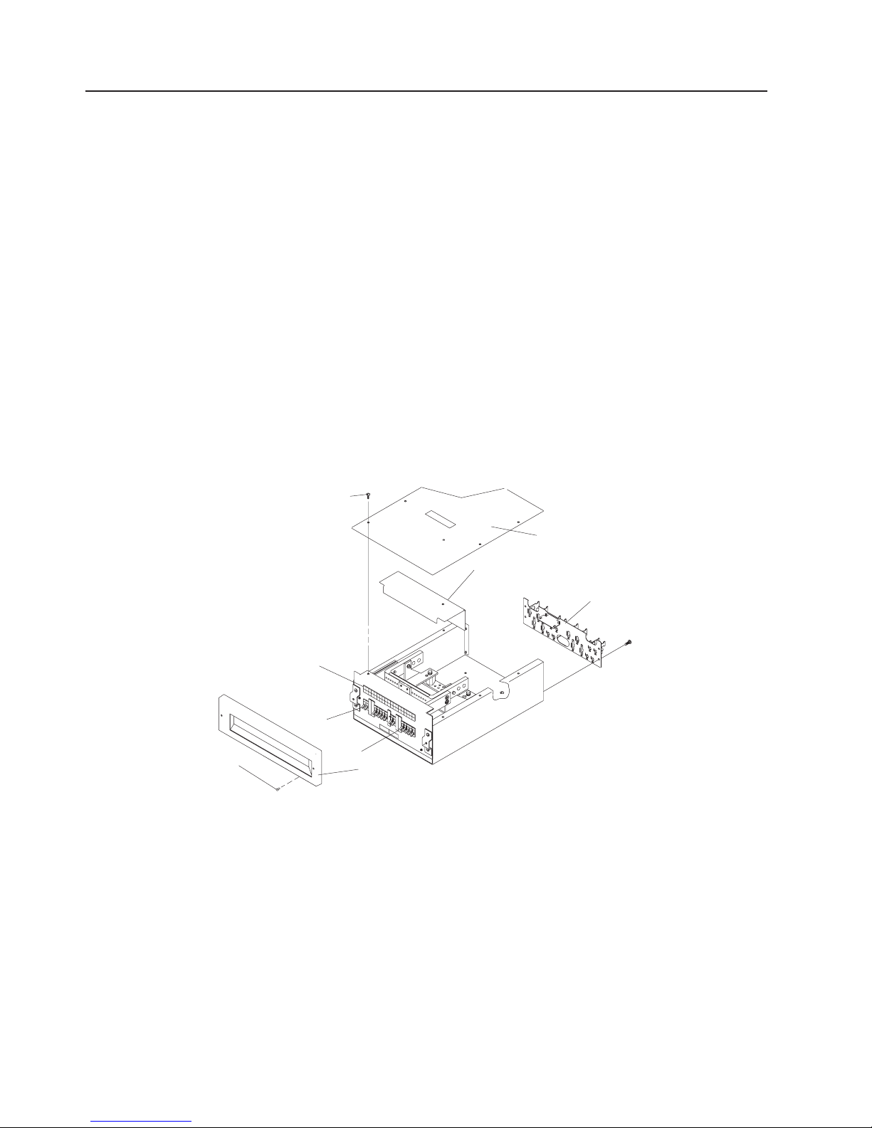
Chapter 4. Parts Information
This chapter contains detailed drawings, field replaceable unit (FRU) part numbers, and part descriptions
for a 7014 Series Model T00 and T42 rack.
Covers
3
10
1
7
11
12
8
4
2
5
Table 1. Frames, Side Panels, and Top Cover
Index Number
FRU Part Number
05N4868
05N4867
11P0313
11P0314
05N6478
7
11
6
Units Per Assembly
Description
Frame (T00, black, 1.8 m)
Frame (T00, white, 1.8 m)
Frame (T42, black, 2.0 m)
Frame (T42, white, 2.0 m)
Side panel (T00 & T42,
black)
41
Page 54

2
3
1
1
9
11
4
1
1
1
1
1
1
1
1
5
2
5
2
2
6
1
1
7
4
8 2
5
2
6
1
7
4
8
2
42
Table 1. Frames, Side Panels, and Top Cover (continued)
Index Number
FRU Part Number
05N6477
21L4290
21L4277
51H9502
Table 2. Front Door
Index Number
FRU Part Number
Note: See Table 3 for Mounting Hardware for the following:
05N4863
11P0319
12K0456
11P0318
32P1029
45P1429
Note: See Table 4 for Mounting Hardware for the following:
21P4049
21P4729
Units Per Assembly
Units Per Assembly
Description
Side panel (T00 & T42,
white)
To p cover (T00 & T42,
white, T42 cable access)
To p cover (T00 & T42,
black, T42 cable access)
Hook-and-loop fastener
Description
T00, RS/6000, black (55
mm)
T42, RS/6000, black (55
mm)
T00, white (35 mm)
T42, white (35 mm)
T00, High Perforation front
door for 1.8M racks, black
T42, High Perforation front
door for 2M racks, black
T00, (100 mm)
T42, (100 mm)
Table 3. Mounting Hardware for RS/6000 and High Perforation Front Door
Index Number
FRU Part Number
Units Per Assembly
31L7547
09N9686
05N4865
31L7545
05N4866
31L8594
Table 4. Mounting Hardware for Front Door
Index Number
FRU Part Number
Units Per Assembly
21P4042
21P4043
31L8594
31L7540
Description
Hinge (55 mm)
Hinge (High Perforation
front Door)
Hinge (35 mm)
Latch plate (55 mm)
Latch plate (35 mm)
Screw
Screw
Description
Hinge (100 mm)
Latch plate (100 mm)
Screw
Screw
7014 Model T00, and Model T42 Service Guide
Page 55

10
1
1
1
1
7
4
8
2
11
2
12
1
Table 5. Rear Door
Index Number
FRU Part Number
Note: See Table 6 for Mounting Hardware
11P0725
11P0723
21P4468
21P4467
Table 6. Mounting Hardware for Rear Door
Index Number
FRU Part Number
31L8594
31L7540
31L7533
31L7531
Units Per Assembly
Units Per Assembly
Description
T00, with foam, round,
white (20 mm)
T42, with foam, round,
white (20 mm)
T00, with foam, hex, black
(20 mm)
T42, with foam, hex, black
(20 mm)
Description
Screw
Screw
Hinge (20 mm)
Latch plate (20 mm)
Chapter 4. Parts Information
43
Page 56

1
1
**
1a
1
1a
1
2
2
2
2
3
2
3
2
4
1
4
1
44
Model T42 Top Frame
Index Number
FRU Part Number
**21L4296
Units Per Assembly
Description
To p Frame
This is the only orderable top frame FRU number. This part has a default color of white. If you need to have a
black top frame, you will need to request it when placing the order along with the 21L4296 FRU part number.
21L4277
To p Cable Access Cover
(Black)
21L4290
To p Cable Access Cover
(White)
31L7536
To p Frame Side Panel
(Black)
05N6805
To p Frame Side Panel
(White)
05N6478
05N6477
11P0313
11P0314
7014 Model T00, and Model T42 Service Guide
Lower Side Panel (Black)
Lower Side Panel (White)
Rack Frame (Black)
Rack Frame (White)
Page 57

1
1
2 * 2
3 * 1
4 * 7
5
1
*
Earthquake Brace
3
2
1
Index Number
Shown for reference only.
5
4
FRU Part Number
05N4697
76X4687
Units Per Assembly
Description
Earthquake brace kit
Hinge
Spacer
Screw
Bolt
Chapter 4. Parts Information
45
Page 58

1
As
1U
As
1U
2
As
3U
As
3U
3
As
4
As
3U
5
M5
M5
6
M5 X 14
M5 X 14
46
Blank Fillers
1
5
Index Number
5
3
2
6
5
6
4
FRU Part Number
97H9754
62X3443
97H9755
62X3444
12J4072
12J4073
74F1823
74F1823
1624779
1624779
6
Units Per Assembly
needed
needed
needed
needed
needed
needed
2/Item3
4/Item4
2/Item3
4/Item4
5
Description
Filler snap (black)
Filler snap (white)
Filler snap (black)
Filler snap (white)
Filler screw (black)
Nut clip
Nut clip
Hex flange
Hex flange
7014 Model T00, and Model T42 Service Guide
Page 59

1
1
1
1
1
1
1
1
Power Distribution Bus
Index Number
FRU Part Number
00P2200
00P2201
00P2202
00P22023
00P3663
00P3665
00P3667
2
Units Per Assembly
1
3
Description
Type 6 power distribution
panel (1 phase U.S.)
Type 6 power distribution
panel (2/3 phase)
Type 6 power distribution
panel (3 phase)
Type 6 power distribution
panel (1 Phase World
Trade)
Type 7 Power distribution
panel (1 Phase)
Type 7 Power distribution
panel (1 Phase World
Trade)
Type 7 Power distribution
panel (3 Phase World
Trade)
Chapter 4. Parts Information
47
Page 60

1
2
4
3
4
1
1
1
1
48
Index Number
FRU Part Number
26K4247
Units Per Assembly
Description
9188/7188 Power
distribution panel (requires
the L-bracket; screws from
the existing 9188/7188
power distribution bus be
removed and added to the
FRU)
1624779
74F1823
Nut Clip
Screw
Note: For information on type 6 and type 7 power distribution buses, see “AC Power Distribution Bus” on
page 2.
Stabilizers
1
2
3
4
Index Number
FRU Part Number
31L8305
31L8306
7014 Model T00, and Model T42 Service Guide
Units Per Assembly
Description
Front stabilizer kit (black)
Front stabilizer kit (white)
Page 61

2
1
2
1
* * 4
*
1
6
2
1
3
1
4
2
5 *
6 1
Index Number
FRU Part Number
Units Per Assembly
44P1850
44P1851
Shown for reference only. Screws are included in the stabilizer kits.
Power Distribution Panel Assembly
1
Description
Rear stabilizer kit (black)
Rear stabilizer kit (white)
Screw, M8X25 button head
(shipped as part of
stabilizer kit)
2
Index Number
6
5
4
3
FRU Part Number
1621191
88G4824
93H4918
93H4919
Units Per Assembly
varies
Description
Screw, M4 x 10
Bus bar shield
Front bezel
Screws, 10-32 button head
Filler plate for empty circuit
breaker positions
I/O Panel
Chapter 4. Parts Information
49
Page 62

7
1
5
20
30
50
*
1
20
30
50
50
Index Number
FRU Part Number
93H7601
93H7600
08L0335
93H6391
8185537
Shown for reference only.
Power Distribution Panel Interior
Units Per Assembly
varies
varies
varies
varies
varies
Description
Amp Circuit Breaker
Amp Circuit Breaker
Amp Circuit Breaker
Amp Circuit Breaker
Amp Circuit Breaker
Index Number
FRU Part Number
00P1793
11K0402
11K0401
7014 Model T00, and Model T42 Service Guide
Units Per Assembly
varies
varies
varies
Description
Amp cable
Amp cable
Amp cable
Page 63

1 * 4
2 * 4
3
1
*
Leveling Feet
1
Index Number
1
2
1
2
1
2
2
3
FRU Part Number
Units Per Assembly
Description
Jam nut
Leveling Feet
31L8313
Wrench
Shown for reference only.
Chapter 4. Parts Information
51
Page 64

1
2
2 * 4
*
52
Model T42 Brace
1
1
2
Rear of Rack
2
Index Number
Shown for reference only.
FRU Part Number
12K0489
Units Per Assembly
Description
Brace
Bolt
7014 Model T00, and Model T42 Service Guide
Page 65

1
1
2
1
3
1
4
2
5
1
6
1
7
1
1
Rack Beacon Assembly
6
Index Number
Not Shown
Not Shown
4
7
1
2
FRU Part Number
53P1775
53P1774
53P2231
53P1776
53P3997
53P1777
53P2236
53P2237
53P2854
5
4
Units Per Assembly
Varies
3
Description
Cover
Power Supply
Junction Box Assembly
Arm
Card Assembly
Lens
Cable
USB Cable
USB Cable
Chapter 4. Parts Information
53
Page 66

1
2 AC
1
2 AC
3
1
4
1
5
1
6
1
7
1
8
2
9
2
10
1
11
1
12
1
13
1
14
1
15
1
16
1
17
1
54
Model T42 Kits (For Reference Only)
Index Number
FRU Part Number
05N4696
05N4695
31L8301
05N6800
11P0488
11P0463
11P0489
31L8305
31L8306
05N4697
31L8302
05N4658
11P0423
11P0424
03N3281
03N3726
11K0928
Units Per Assembly
Description
plate assembly (black)
plate assembly (white)
Bolt down
Trim decorative (black T00
only)
Trim decorative (white T00
only)
Trim decorative (black T42
only)
Trim decorative (white T42
only)
Stabilizer (black)
Stabilizer (white)
Earthquake brace
Attachment (black T00 only)
Attachment (white T00 only)
Attachment (white T42 only)
Attachment (white only)
To p cable tray (white)
To p cable tray (end cover)
Rack ground kit
7014 Model T00, and Model T42 Service Guide
Page 67

1
1
30 A,
1
1
6
30 A,
1
1
30 A,
Power Cords
Index Number
1
2
FRU Part Number
3
4
Units Per Assembly
11F0113
5
6
Country or Region
U.S. Standard, type 12
plug, L6-30P twist-lock
connector, 14 foot cord
single phase
U.S.A., Canada
Anguilla, Antigua, Cape
Verde Islands, Cayman
Islands, French Polynesia,
Honduras, Montserrat, St.
Kitts & Nevis, Tortola
11F0114
U.S., Chicago, type 12 plug,
L6-30P twist-lock connector,
foot cord
single phase
Chicago, Illinois, U.S.A.
11F0115
AFE, type 12 plug, L6-30P
twist-lock connector, 14 foot
cord
single phase
Afghanistan, Argentina,
Aruba, Bahamas,
Bangladesh, Barbados,
Belize, Bermuda, Bolivia,
Bonnaire, Brunei, Caicos
Islands, Chile, Colombia,
Costa Rica, Curaçao,
Dominican Republic,
Ecuador, El Salvador,
Guatemala, Hong Kong
S.A.R. of China, Indonesia,
Jamaica, Japan, Malaysia,
Mexico, Myanmar,
Netherlands Antilles,
Nicaragua, Panama,
Paraguay, People’s
Republic of China, Peru,
Philippines, St. Martin,
Singapore, Sri Lanka,
Suriname, Taiwan, Thailand,
Trinidad/Tobago, Turks
Island, Uruguay, Venezuela
Chapter 4. Parts Information
55
Page 68

1
1
1
1
1
1
1
1
1
1
1
2
1 3
14
30 A,
2
1
6
30 A,
3
1 30 A,
14
56
Index Number
64P1246
64P1247
64P1248
64P1249
64P1250
64P1251
64P1252
FRU Part Number
64P1244
64P1245
46F4594
Units Per Assembly
Country or Region
Linecord, PDU to wall, 14
foot (3PH/24A, UTG0247,
IEC309 32A 3P+N+G)
Linecord, PDU to wall, 14
foot (200-240V/48A,
UTG0247, IEC309 63A
P+N+G)
Linecord, PDU to wall, 14
foot (200-240V/48A,
UTG0247, IEC309 60A
2P+G)
Linecord, PDU to wall, 14
foot (3PH/16A, UTG0247,
IEC309 16A 3P+N+G)
Linecord, PDU to wall, 14
foot (200-240V/24A,
UTG0247, PT#12)
Linecord, PDU to wall, 14
foot (200-240V/24A,
UTG0247, PT#40)
Linecord, PDU to wall, 14
foot (200-240V/24A,
UTG0247, IEC309 32A
P+N+G)
Linecord, PDU to wall, 14
foot (200-240V/24A,
UTG0247, PT#PDL)
Linecord, PDU to wall, 14
foot (200-240V/24A,
UTG0247, PT#KP)
pin waterproof connector,
foot cord
46F4593
11F0106
7014 Model T00, and Model T42 Service Guide
Type 40 plug, R&S 3750
single phase
U.S.A., Canada
(weatherproof)
3-pin waterproof connector,
foot cord
Type 40 plug, R&S 3750
single phase
Chicago, Illinois, U.S.A.
single phase, PDL
connector
Wilco WP, type PDL plug,
foot cord
Australia
Page 69

3
1 30 A,
14
Index Number
FRU Part Number
11F0107
Units Per Assembly
Country or Region
single phase, PDL
connector
Wilco WP, type PDL plug,
foot cord
Australia
Chapter 4. Parts Information
57
Page 70

4
1 32 A,
(2
of
58
Index Number
FRU Part Number
21H7693
Units Per Assembly
Country or Region
single phase, three
pin connector
IEC 309, type 46 connector
power + ground), 14 foot
cord
Abu Dubai, Albania, Algeria,
Angola, Armenia, Bahrain,
Belarus, Belgium, Benin,
Bosnia, Botswana, Brazil,
Bulgaria, Burkina Faso,
Burundi, Cambodia,
Cameroon, Congo, Croatia,
Cyprus, Djibouti, Dominica,
Egypt, Equitorial Guinea,
Ethiopia, France, French
Guiana, Gabon, Gambia,
Georgia, Germany, Ghana,
Greece, Grenada,
Grenadines, Guinea,
Guinea-Bissau, Guyana,
Haiti, Hungary, Iceland,
India, Iran, Iraq, Ireland,
Italy, Ivory Coast, Jordan,
Kazakhstan, Kenya,
Kirhizia, Kuwait, Lesotho,
Lebanon, Liberia, Libya,
Luxembourg, Macao S.A.R.
China, Macedonia,
Malawi, Mali, Malta,
Martinique, Mauritania,
Moldovia, Monaco,
Morocco, Mozambique,
Namibia, Nepal,
Netherlands, New
Caledonia, Niger, Nigeria,
North Yemen, Oman,
Pakistan, Poland, Principe,
Qatar, Reunion, Romania,
Rwanda, St. Lucia, St.
Vincent, Sao Thome Island,
Saudi Arabia, Senegal,
Serbia, Sierra Leone,
Slovakia, Slovenia,
Somalia, South Yemen,
Spain, Sudan, Swaziland,
Syria, Tanzania, Togo,
Tunisia, Uganda, Ukraine,
United Arab Emirates,
United Kingdom, Vietnam,
Western Samoa, Zaire,
Zambia, Zimbabwe
7014 Model T00, and Model T42 Service Guide
Page 71

5
1 32 A, 2 of 3
(3
5
1 16 A, 3
(3
6
1 30 A,
Index Number
FRU Part Number
88G4763
88G4764
87G6067
Units Per Assembly
Country or Region
phase, five pin
connector
IEC 309, type 46 connector
power + neutral +
ground), 14 foot cord
Austria, Czech Republic,
Denmark, Estonia, Finland,
Israel, Latvia, Liechtenstein,
Lithuania, Netherlands,
Norway, Pakistan, Portugal,
Russia, South Africa,
Sweden, Turkey
phase, five pin
connector
IEC 309, type 46 connector
power + neutral +
ground), 14 foot cord
Switzerland
Single Phase
Type KP connector, right
angle, 14 foot cord
Korea
Chapter 4. Parts Information
59
Page 72

60
7014 Model T00, and Model T42 Service Guide
Page 73

at
Appendix A. Environmental Notices
Product Recycling and Disposal
This unit contains materials such as circuit boards, cables, electromagnetic compatibility gaskets and
connectors which may contain lead and copper/beryllium alloys that require special handling and disposal
end of life. Before this unit is disposed of, these materials must be removed and recycled or discarded
according to applicable regulations. IBM offers product-return programs in several countries. For country
specific instructions refer to the following web site: http://www.ibm.com/ibm/environment/products/prp.phtml
This product may contain a sealed lead acid, nickel cadmium, nickel metal hydride, lithium, or
lithium ion battery. Consult your user manual or service manual for specific battery information.
The battery must be recycled or disposed of properly. Recycling facilities may not be available in
your area. For information on disposal of batteries, contact your local waste disposal facility.
61
Page 74

Dette produkt kan indeholde et forseglet batteri, der indeholder bly,
nikkel-kadmium, nikkel-metal-hydrid, litium eller litium-ion.
Der er flere oplysninger om batteriet i bruger- eller servicevejledningen.
Batteriet må ikke kasseres sammen med det almindelige affald.
Batteriet skal kasseres i henhold til de lokale bestemmelser.
Spørg eventuelt kommunens tekniske forvaltning (Miljøafdelingen).
Dit product bevat mogelijk een afgesloten batterij van het type lood/zuur ,
nikkel/cadmium, nikkel/metaalhydride, lithium, of lithiumionen. Raadpleeg
het handboek voor de gebruiker of het servicehandboek voor informatie over
de batterij. De batterij moet correct worden gerecycled of weggegooid.
Mogelijk zijn er in uw regio geen K CA-inzamelingspunten. Meer
informatie over het verwerken van gebruikte batterijen kunt u verkrijgen bij
uw afvalverwerkingsbedrijf .
Dieses Produkt enthält eine auslaufsichere Blei-, Nickel-Cadmium-, Nickelmetallhydrid-, Lithium- oder Lithiumionenbatterie. Spezifische Informationen
zur Batterie entnehmen Sie bitte dem Benutzer- oder Servicehandbuch. Die
Batterie muss wieder verwertet oder als Sondermüll entsorgt werden. Es ist
möglich, dass es in Ihrer Nähe keine Wiederverwertungsanlage gibt. Weitere
Informationen zur Entsorgung von Batterien erhalten Sie von Ihrem örtlichen
Müllentsorgungsunternehmen.
62
7014 Model T00, and Model T42 Service Guide
Page 75

Questo prodotto potrebbe contenere una batteria al piombo, al
nichel-cadmio, all ’idruro di nichel, al litio o agli ioni di litio. Consultare il
manuale utente o il manuale di assistenza per informazioni specifiche sulla
batteria. La batteria deve essere appropriatamente riciclata o smaltita.
Il servizio per il riciclaggio potrebbero non essere disponibile nella vostra
zona. Per informazioni sullo smaltimento delle batterie, contattare l ’azienda
preposta per lo smaltimento dei rifiuti.
Appendix A. Environmental Notices
63
Page 76

Produkten kan innehålla ett förseglat batteri av någon av typerna
blyackumulator , nickel-kadmium, nickel-metallhydrid, litium eller litiumjon.
Detaljerad batteriinformation finns I användar - eller servicehandboken.
Batteriet måste lämnas till återvinning eller kastas på ett miljösäkert sätt.
Det kanske inte finns några återvinningsmöjligheter där du bor . När det
gäller omhändertagande av batterier ber vi att få hänvisa till myndigheternas
anvisningar i respektive land.
64
7014 Model T00, and Model T42 Service Guide
Page 77

of
In the United States, IBM has established a collection process for reuse, recycling, or proper disposal of
used IBM sealed lead acid, nickel cadmium, nickel metal hydride, and other battery packs from IBM
Equipment. For information on proper disposal of these batteries, please contact IBM at 1-800-426-4333.
Have the IBM part number listed on the battery available prior to your call.
Environmental Design
The environmental efforts that have gone into the design of this system signify IBM’s commitment to
improve the quality of its products and processes. Some of these accomplishments include the elimination
the use of Class 1 ozone-depleting chemicals in the manufacturing process and reductions in
manufacturing wastes. For more information, contact an IBM account representative.
Appendix A. Environmental Notices
65
Page 78

66
Acoustical Noise Emissions
The equivalent continuous A-weighted sound pressure level at workstations (emission sound pressure
level at the 1-meter bystander positions) does not exceed 70 dB(A).
Der Geräuschpegel der Einheit ist kleiner oder gleich 70 db(A).
Declared Acoustical Noise Emissions
There is no declared acoustical noise emission for the system rack. The declared acoustical noise
emissions can be found in the service guides for each of the system drawers installed into the 7014 Series
Model T00 and Model T42 System Rack.
7014 Model T00, and Model T42 Service Guide
Page 79

in
Appendix B. Notices
This information was developed for products and services offered in the U.S.A.
The manufacturer may not offer the products, services, or features discussed in this document in other
countries. Consult the manufacturer’s representative for information on the products and services currently
available in your area. Any reference to the manufacturer’s product, program, or service is not intended to
state or imply that only that product, program, or service may be used. Any functionally equivalent product,
program, or service that does not infringe any intellectual property right of the manufacturer may be used
instead. However, it is the user’s responsibility to evaluate and verify the operation of any product,
program, or service.
The manufacturer may have patents or pending patent applications covering subject matter described in
this document. The furnishing of this document does not give you any license to these patents. You can
send license inquiries, in writing, to the manufacturer.
The following paragraph does not apply to the United Kingdom or any country where such
provisions are inconsistent with local law: THIS MANUAL IS PROVIDED ″AS IS″ WITHOUT
WARRANTY OF ANY KIND, EITHER EXPRESSED OR IMPLIED, INCLUDING, BUT NOT LIMITED TO,
THE IMPLIED WARRANTIES OF NON-INFRINGEMENT, MERCHANTABILITY OR FITNESS FOR A
PARTICULAR PURPOSE. Some states do not allow disclaimer of express or implied warranties in certain
transactions; therefore, this statement may not apply to you.
This information could include technical inaccuracies or typographical errors. Changes are periodically
made to the information herein; these changes will be incorporated in new editions of the publication. The
manufacturer may make improvements and/or changes in the product(s) and/or the program(s) described
this publication at any time without notice.
Information concerning products made by other than the manufacturer was obtained from the suppliers of
those products, their published announcements, or other publicly available sources. The manufacturer has
not tested those products and cannot confirm the accuracy of performance, compatibility or any other
claims related to products made by other than the manufacturer. Questions on the capabilities of products
made by other than the manufacturer should be addressed to the suppliers of those products.
67
Page 80

68
7014 Model T00, and Model T42 Service Guide
Page 81

ac
ac
ac
ac
ac
66
dc
dc
dc
dc
dc
dc
dc
66
66
ix
Index
Special characters
-48 v dc circuit breaker removal and replacement 36
A
about this book ix
power distribution bus 2
power distribution bus illustration 9
power distribution bus power-off procedure 27
power distribution bus power-on procedure 25
power distribution bus removal and replacement 29
accessing information ix
acoustical
noise
emissions
B
battery
disposal,
recycling 61
blank fillers, rack 46
bus illustration, ac power distribution 9
C
covers 41
I
information, accessing ix
K
kits 54
L
laser vi
laser compliance statement vi
laser compliance statement vi
laser safety information vi
leveling feet parts 51
M
Maintenance Analysis Procedures (MAPs) 17
MAP 1520: dc power distribution panel power 17
MAP 1522: ac power distribution bus-power 21
Model T42 brace 52
N
noise
emissions
D
dc power distribution and ground illustration 11
power distribution panel 10
power distribution panel power-off procedure 29
power distribution panel power-on procedure 27
power distribution panel removal and
replacement 31
rack configuration 11
rack information 10
rack power cables 12
E
earthquake brace 45
emissions
noise
external ac power cables 9
F
front or rear door removal and replacement 39
H
highlighting ix
O
online publications ix
P
parts information 41
blank fillers 46
covers 41
earthquake brace 45
kits 54
leveling feet 51
Model T42 brace 52
power cords 55
power distribution bus 47
power distribution panel assembly 49
power distribution panel interior 50
stabilizers 48
power cables, external ac 9
power cords 55
power distribution bus parts 47
power distribution panel assembly parts 49
power distribution panel interior parts 50
power source, uninterruptible 9
preface ix
product disposal 61
publications
accessing
online ix
69
Page 82

ac
ac
dc
dc
dc
dc
dc
70
publications, online ix
R
rack specifications 13
rack, relocating 40
recycling 61
reference information 1
power cables, external 9
rack information 2
bus, ac power distribution 2
cables, external ac power 9
power distribution and ground illustration 11
power distribution panel 10
rack configuration 11
rack information 10
rack power cables 12
illustration, ac power distribution bus 9
power distribution types 1
rack dimensions 13
rack information, ac 2
rack installation airflow 13
rack power requirements 13
rack specifications 13
rack weight 13
service inspection guide 14
types, power distribution 1
uninterruptible power source 9
related publications ix
removal and replacement procedures 25
operating system shutdown 25
power-off procedure with ac power distribution
bus 27
power-off procedure with dc power distribution
panel 29
power-on procedure with ac power distribution
bus 25
power-on procedure with dc power distribution
panel 27
relocating racks 40
removal and replacement of -48 v dc circuit
breaker 36
removal and replacement of ac power distribution
bus 29
removal and replacement of dc power distribution
panel 31
removal and replacement of front or rear door 39
removal and replacement procedures 25
U
uninterruptible power source 9
S
safety notices v
laser compliance statement vi
service inspection guide 14
stabilizers 48
T
trademarks ix
types of power distribution 1
7014 Model T00, and Model T42 Service Guide
Page 83

h
h No
Readers’ Comments — We’d Like to Hear from You
7014 Series Model T00 and Model T42 System Rack
Service Guide
Publication No. SA38-0577-05
Overall, how satisfied are you with the information in this book?
Very Satisfied Satisfied Neutral Dissatisfied Very Dissatisfied
Overall satisfaction hhhhh
How satisfied are you that the information in this book is:
Very Satisfied Satisfied Neutral Dissatisfied Very Dissatisfied
Accurate hhhhh
Complete hhhhh
Easy to find hhhhh
Easy to understand hhhhh
Well organized hhhhh
Applicable to your tasks hhhhh
Please tell us how we can improve this book:
Thank you for your responses. May we contact you?
When you send comments to IBM, you grant IBM a nonexclusive right to use or distribute your comments in any
way it believes appropriate without incurring any obligation to you.
Name
Company or Organization
Phone No.
Yes
Address
Page 84

or
___________________________________________________________________________________________________
Readers’ Comments — We’d Like to Hear from You
SA38-0577-05
Fold
_________________________________________________________________________________________
and Tape
Please do not staple
Fold and Tape
NO
POSTAGE
NECESSARY
MAILED IN THE
IF
UNITED STATES
Cut or Fold
Along Line
BUSINESS REPLY MAIL
FIRST-CLASS MAIL PERMIT NO. 40 ARMONK, NEW YORK
POSTAGE WILL BE PAI D BY ADDRESSEE
Information Development
Department H6DS-905-6C006
11501 Burnet Road
Austin, TX 78758-3493
_________________________________________________________________________________________
Fold
and Tape
Please do not staple
Fold and Tape
SA38-0577-05
Fold
Cut
Along Line
Page 85

Page 86

Printed in USA
November 2003
SA38-0577-05
 Loading...