

Page 1

7013 J Series
Operator Guide
SA23-2724-02
Page 2

Third Edition (April 1997)
This edition notice applies to the
7013 J Series Operator Guide.
This edition obsoletes all previous editions
.
The following paragraph does not apply to the United Kingdom or any country where such
provisions are inconsistent with local law: THIS PUBLICATION IS PRINTED “AS IS” WITHOUT
WARRANTY OF ANY KIND, EITHER EXPRESS OR IMPLIED, INCLUDING, BUT NOT LIMITED TO, THE
IMPLIED WARRANTIES OF MERCHANTABILITY OR FITNESS FOR A PARTICULAR PURPOSE. Some
states do not allow disclaimer of express or implied warranties in certain transactions; therefore, this
statement may not apply to you.
This publication could include technical inaccuracies or typographical errors. Changes are periodically made
to the information herein; these changes will be incorporated in new editions of the publication. The
manufacturer may make improvements and/or changes in the product(s) and/or program(s) described in this
publication at any time, without notice.
It is possible that this publication may contain reference to, or information about, products (machines and
programs), programming, or services that are not announced in your country. Such references or information
must not be construed to mean that such products, programming, or services will be offered in your country.
Any reference to a licensed program in this publication is not intended to state or imply that you can use only
the licensed program indicated. You can use any functionally equivalent program instead.
AIX is a registered trademark of International Business Machines.
Medeco is a trademark of Medeco Company.
Micro Channel is a trademark of International Business Machines.
SystemGuard is a trademark of International Business Machines.
Velcro is a trademark of Velcro Industries.
Copyright International Business Machines Corporation, 1994, 1997. All rights reserved.
Note to U.S. Government Users – Documentation and programs related to restricted rights – Use,
duplication, or disclosure is subject to the restrictions set forth in the GSA ADP Schedule Contract.
Page 3

Preface iii
Table of Contents
Communications Statements ix. . . . . . . . . . . . . . . . . . . . . . . . . . . . . . . . . . . . . . . . . . . .
Safety Notices xiii. . . . . . . . . . . . . . . . . . . . . . . . . . . . . . . . . . . . . . . . . . . . . . . . . . . . . . . . . .
About This Book xvii. . . . . . . . . . . . . . . . . . . . . . . . . . . . . . . . . . . . . . . . . . . . . . . . . . . . . . . .
Chapter 1. Description of the 7013 J Series System 1-1. . . . . . . . . . . . . . . . . . . . . . .
Description of the Base Unit 1-1. . . . . . . . . . . . . . . . . . . . . . . . . . . . . . . . . . . . . . . . . . . . . . .
Base Unit Without Covers 1-3. . . . . . . . . . . . . . . . . . . . . . . . . . . . . . . . . . . . . . . . . . . . . .
Operator Controls 1-4. . . . . . . . . . . . . . . . . . . . . . . . . . . . . . . . . . . . . . . . . . . . . . . . . . . . .
Media Devices 1-5. . . . . . . . . . . . . . . . . . . . . . . . . . . . . . . . . . . . . . . . . . . . . . . . . . . . . . . . . .
Base Unit 1-5. . . . . . . . . . . . . . . . . . . . . . . . . . . . . . . . . . . . . . . . . . . . . . . . . . . . . . . . . . . . .
Description of the Expansion Unit 1-6. . . . . . . . . . . . . . . . . . . . . . . . . . . . . . . . . . . . . . . . . .
Expansion Unit 1-7. . . . . . . . . . . . . . . . . . . . . . . . . . . . . . . . . . . . . . . . . . . . . . . . . . . . . . . .
Main Power Switch Module 1-9. . . . . . . . . . . . . . . . . . . . . . . . . . . . . . . . . . . . . . . . . . . . . . .
System Unit Main Switch 1-9. . . . . . . . . . . . . . . . . . . . . . . . . . . . . . . . . . . . . . . . . . . . . . .
Location Codes 1-10. . . . . . . . . . . . . . . . . . . . . . . . . . . . . . . . . . . . . . . . . . . . . . . . . . . . . . . . . .
Location Code Format for SCSI Devices 1-10. . . . . . . . . . . . . . . . . . . . . . . . . . . . . . . . . .
Location Code Format for Non-SCSI Devices 1-10. . . . . . . . . . . . . . . . . . . . . . . . . . . . .
Location Code Format for 7135, 9333, and 9334 Expansion Units 1-10. . . . . . . . . . .
Location Code Table for SCSI and Non-SCSI Devices 1-11. . . . . . . . . . . . . . . . . . . . . .
Cluster Power Control 1-13. . . . . . . . . . . . . . . . . . . . . . . . . . . . . . . . . . . . . . . . . . . . . . . . . .
Chapter 2. Using the System Unit 2-1. . . . . . . . . . . . . . . . . . . . . . . . . . . . . . . . . . . . . . . .
Main Power Switch Module 2-1. . . . . . . . . . . . . . . . . . . . . . . . . . . . . . . . . . . . . . . . . . . . . . .
The Operator Panel 2-3. . . . . . . . . . . . . . . . . . . . . . . . . . . . . . . . . . . . . . . . . . . . . . . . . . . . . .
Operator Controls 2-3. . . . . . . . . . . . . . . . . . . . . . . . . . . . . . . . . . . . . . . . . . . . . . . . . . . . .
Setting the Key Mode Switch 2-6. . . . . . . . . . . . . . . . . . . . . . . . . . . . . . . . . . . . . . . . . . . .
Starting and Stopping the System Unit 2-9. . . . . . . . . . . . . . . . . . . . . . . . . . . . . . . . . . . . . .
Methods of Starting the System Unit 2-9. . . . . . . . . . . . . . . . . . . . . . . . . . . . . . . . . . . . .
Manually Starting the System Unit 2-10. . . . . . . . . . . . . . . . . . . . . . . . . . . . . . . . . . . . . . .
Manually Stopping the System Unit 2-11. . . . . . . . . . . . . . . . . . . . . . . . . . . . . . . . . . . . . .
General Information about Multiple Systems 2-12. . . . . . . . . . . . . . . . . . . . . . . . . . . . . .
Terminals and Printers 2-13. . . . . . . . . . . . . . . . . . . . . . . . . . . . . . . . . . . . . . . . . . . . . . . . . . . .
System Consoles 2-13. . . . . . . . . . . . . . . . . . . . . . . . . . . . . . . . . . . . . . . . . . . . . . . . . . . . . .
Using Internal Mass Storage Devices 2-14. . . . . . . . . . . . . . . . . . . . . . . . . . . . . . . . . . . . . . .
Using the 8 mm Tape Drive 2-15. . . . . . . . . . . . . . . . . . . . . . . . . . . . . . . . . . . . . . . . . . . . . . .
Functions 2-15. . . . . . . . . . . . . . . . . . . . . . . . . . . . . . . . . . . . . . . . . . . . . . . . . . . . . . . . . . . . .
Status Lights 2-16. . . . . . . . . . . . . . . . . . . . . . . . . . . . . . . . . . . . . . . . . . . . . . . . . . . . . . . . . .
Setting the Write-Protect Tab on 8 mm Tape Cartridges 2-17. . . . . . . . . . . . . . . . . . . . .
Performance 2-17. . . . . . . . . . . . . . . . . . . . . . . . . . . . . . . . . . . . . . . . . . . . . . . . . . . . . . . . . .
Usage 2-17. . . . . . . . . . . . . . . . . . . . . . . . . . . . . . . . . . . . . . . . . . . . . . . . . . . . . . . . . . . . . . .
Loading the 8 mm Tape Cartridge 2-18. . . . . . . . . . . . . . . . . . . . . . . . . . . . . . . . . . . . . . .
Unloading the 8 mm Tape Cartridge 2-19. . . . . . . . . . . . . . . . . . . . . . . . . . . . . . . . . . . . . .
Types of 8 mm Tape Cartridges 2-20. . . . . . . . . . . . . . . . . . . . . . . . . . . . . . . . . . . . . . . . .
Page 4

iv Operator Guide
Preventive Maintenance 2-20. . . . . . . . . . . . . . . . . . . . . . . . . . . . . . . . . . . . . . . . . . . . . . . . . .
Cleaning the Tape Path on the 5GB 8 mm Tape Drive 2-20. . . . . . . . . . . . . . . . . . . . . .
Loading the 8 mm Cleaning Cartridge 2-21. . . . . . . . . . . . . . . . . . . . . . . . . . . . . . . . . . . .
Tape Handling 2-21. . . . . . . . . . . . . . . . . . . . . . . . . . . . . . . . . . . . . . . . . . . . . . . . . . . . . . . .
General Information for 4.0GB 4 mm Tape Drive 2-24. . . . . . . . . . . . . . . . . . . . . . . . . . . . .
Recommendations 2-25. . . . . . . . . . . . . . . . . . . . . . . . . . . . . . . . . . . . . . . . . . . . . . . . . . . . .
Types of 4 mm Tape Cartridges 2-25. . . . . . . . . . . . . . . . . . . . . . . . . . . . . . . . . . . . . . . . .
Tape Cartridge Compatibility 2-26. . . . . . . . . . . . . . . . . . . . . . . . . . . . . . . . . . . . . . . . . . . .
Setting the Write-Protect Tab on 4 mm Tape Cartridges 2-26. . . . . . . . . . . . . . . . . . . . .
Environmental Considerations for 4 mm Data Cartridges 2-26. . . . . . . . . . . . . . . . . . .
Operating in Harsh Environments 2-27. . . . . . . . . . . . . . . . . . . . . . . . . . . . . . . . . . . . . . . .
4 mm Data Cartridge Erasure 2-27. . . . . . . . . . . . . . . . . . . . . . . . . . . . . . . . . . . . . . . . . . .
Tape Cartridge Data Capacity 2-27. . . . . . . . . . . . . . . . . . . . . . . . . . . . . . . . . . . . . . . . . . .
Using the 4.0GB 4 mm Tape Drive 2-28. . . . . . . . . . . . . . . . . . . . . . . . . . . . . . . . . . . . . . . . .
Status Lights 2-28. . . . . . . . . . . . . . . . . . . . . . . . . . . . . . . . . . . . . . . . . . . . . . . . . . . . . . . . . .
Loading the 4 mm Tape Cartridge 2-30. . . . . . . . . . . . . . . . . . . . . . . . . . . . . . . . . . . . . . .
Unloading the 4 mm Tape Cartridge 2-31. . . . . . . . . . . . . . . . . . . . . . . . . . . . . . . . . . . . . .
Cleaning the Tape Path on the 4.0GB 4 mm Tape Drive 2-32. . . . . . . . . . . . . . . . . . . .
Using the 1/4-Inch Tape Drive 2-33. . . . . . . . . . . . . . . . . . . . . . . . . . . . . . . . . . . . . . . . . . . . .
Functions 2-33. . . . . . . . . . . . . . . . . . . . . . . . . . . . . . . . . . . . . . . . . . . . . . . . . . . . . . . . . . . . .
Tape Cartridge Compatibility 2-34. . . . . . . . . . . . . . . . . . . . . . . . . . . . . . . . . . . . . . . . . . . .
Loading the 1/4-Inch Tape Cartridge 2-35. . . . . . . . . . . . . . . . . . . . . . . . . . . . . . . . . . . . .
Unloading the 1/4-Inch Tape Cartridge 2-36. . . . . . . . . . . . . . . . . . . . . . . . . . . . . . . . . . .
Setting the Write-Protect Tab on 1/4-Inch Tape Cartridges 2-37. . . . . . . . . . . . . . . . . .
Cleaning the 1/4-Inch Cartridge Drive 2-38. . . . . . . . . . . . . . . . . . . . . . . . . . . . . . . . . . . . . . .
Environmental Considerations for 1/4-Inch Tape Cartridges 2-38. . . . . . . . . . . . . . . . .
Using the CD-ROM Drives 2-39. . . . . . . . . . . . . . . . . . . . . . . . . . . . . . . . . . . . . . . . . . . . . . . .
Loading the CD-ROM Disc Caddy (Type B Bezel Only) 2-40. . . . . . . . . . . . . . . . . . . . .
Loading the CD-ROM Drive (Type C Bezel Only) 2-40. . . . . . . . . . . . . . . . . . . . . . . . . .
Unloading the CD-ROM Disc Caddy 2-41. . . . . . . . . . . . . . . . . . . . . . . . . . . . . . . . . . . . .
Unloading the CD-ROM Drive (Type C Bezel Only) 2-41. . . . . . . . . . . . . . . . . . . . . . . .
Cleaning the CD-ROM Drive 2-41. . . . . . . . . . . . . . . . . . . . . . . . . . . . . . . . . . . . . . . . . . . .
Emergency Eject (Type C Bezel Only) 2-42. . . . . . . . . . . . . . . . . . . . . . . . . . . . . . . . . . . .
Using the 3.5-Inch Diskette Drive 2-43. . . . . . . . . . . . . . . . . . . . . . . . . . . . . . . . . . . . . . . . . .
Functions 2-43. . . . . . . . . . . . . . . . . . . . . . . . . . . . . . . . . . . . . . . . . . . . . . . . . . . . . . . . . . . . .
Handling Your Diskettes 2-43. . . . . . . . . . . . . . . . . . . . . . . . . . . . . . . . . . . . . . . . . . . . . . . .
Types of 3.5-Inch Diskettes 2-44. . . . . . . . . . . . . . . . . . . . . . . . . . . . . . . . . . . . . . . . . . . . .
Setting the Write-Protect Tab 2-45. . . . . . . . . . . . . . . . . . . . . . . . . . . . . . . . . . . . . . . . . . . .
Loading and Unloading the 3.5-Inch Diskette 2-46. . . . . . . . . . . . . . . . . . . . . . . . . . . . . .
Using Internal Disk Drives 2-47. . . . . . . . . . . . . . . . . . . . . . . . . . . . . . . . . . . . . . . . . . . . . . . . .
Operator Controls of a Disk Device 2-47. . . . . . . . . . . . . . . . . . . . . . . . . . . . . . . . . . . . . .
Page 5

Preface v
Chapter 3. Using SystemGuard 3-1. . . . . . . . . . . . . . . . . . . . . . . . . . . . . . . . . . . . . . . . . .
Introduction 3-1. . . . . . . . . . . . . . . . . . . . . . . . . . . . . . . . . . . . . . . . . . . . . . . . . . . . . . . . . . . . .
SystemGuard Power 3-2. . . . . . . . . . . . . . . . . . . . . . . . . . . . . . . . . . . . . . . . . . . . . . . . . . . . .
SystemGuard Components 3-2. . . . . . . . . . . . . . . . . . . . . . . . . . . . . . . . . . . . . . . . . . . . . . .
SystemGuard Bring-Up MicroProcessor Overview 3-2. . . . . . . . . . . . . . . . . . . . . . . . . . . .
The Operator Panel 3-3. . . . . . . . . . . . . . . . . . . . . . . . . . . . . . . . . . . . . . . . . . . . . . . . . . . . . .
SystemGuard Consoles 3-4. . . . . . . . . . . . . . . . . . . . . . . . . . . . . . . . . . . . . . . . . . . . . . . . . .
Physical and Electronic Key 3-4. . . . . . . . . . . . . . . . . . . . . . . . . . . . . . . . . . . . . . . . . . . . . . .
SystemGuard Phases 3-4. . . . . . . . . . . . . . . . . . . . . . . . . . . . . . . . . . . . . . . . . . . . . . . . . . . .
Stand-By Phase 3-4. . . . . . . . . . . . . . . . . . . . . . . . . . . . . . . . . . . . . . . . . . . . . . . . . . . . . . .
Init Phase 3-5. . . . . . . . . . . . . . . . . . . . . . . . . . . . . . . . . . . . . . . . . . . . . . . . . . . . . . . . . . . .
Maintenance Phase 3-5. . . . . . . . . . . . . . . . . . . . . . . . . . . . . . . . . . . . . . . . . . . . . . . . . . . .
Boot Phase 3-5. . . . . . . . . . . . . . . . . . . . . . . . . . . . . . . . . . . . . . . . . . . . . . . . . . . . . . . . . . .
Run-Time Phase 3-5. . . . . . . . . . . . . . . . . . . . . . . . . . . . . . . . . . . . . . . . . . . . . . . . . . . . . .
SystemGuard Parameters and Flags 3-9. . . . . . . . . . . . . . . . . . . . . . . . . . . . . . . . . . . . .
Working with SystemGuard 3-10. . . . . . . . . . . . . . . . . . . . . . . . . . . . . . . . . . . . . . . . . . . . .
SystemGuard Menus 3-11. . . . . . . . . . . . . . . . . . . . . . . . . . . . . . . . . . . . . . . . . . . . . . . . . .
Maintenance Menu 3-21. . . . . . . . . . . . . . . . . . . . . . . . . . . . . . . . . . . . . . . . . . . . . . . . . . . .
Display Configuration 3-22. . . . . . . . . . . . . . . . . . . . . . . . . . . . . . . . . . . . . . . . . . . . . . . . . .
Display BUMP Error Log 3-25. . . . . . . . . . . . . . . . . . . . . . . . . . . . . . . . . . . . . . . . . . . . . . .
Enable Service Console 3-25. . . . . . . . . . . . . . . . . . . . . . . . . . . . . . . . . . . . . . . . . . . . . . . .
Disable Service Console 3-25. . . . . . . . . . . . . . . . . . . . . . . . . . . . . . . . . . . . . . . . . . . . . . .
Reset 3-25. . . . . . . . . . . . . . . . . . . . . . . . . . . . . . . . . . . . . . . . . . . . . . . . . . . . . . . . . . . . . . . .
Power-Off 3-25. . . . . . . . . . . . . . . . . . . . . . . . . . . . . . . . . . . . . . . . . . . . . . . . . . . . . . . . . . . .
System Boot 3-26. . . . . . . . . . . . . . . . . . . . . . . . . . . . . . . . . . . . . . . . . . . . . . . . . . . . . . . . . .
Off-Line Tests 3-28. . . . . . . . . . . . . . . . . . . . . . . . . . . . . . . . . . . . . . . . . . . . . . . . . . . . . . . . .
Set Parameters 3-32. . . . . . . . . . . . . . . . . . . . . . . . . . . . . . . . . . . . . . . . . . . . . . . . . . . . . . .
Set National Language 3-38. . . . . . . . . . . . . . . . . . . . . . . . . . . . . . . . . . . . . . . . . . . . . . . . .
Some Common SystemGuard Tasks 3-39. . . . . . . . . . . . . . . . . . . . . . . . . . . . . . . . . . . . .
Customizing SystemGuard For Your Needs 3-58. . . . . . . . . . . . . . . . . . . . . . . . . . . . . . .
Reloading the Flash EEPROM 3-60. . . . . . . . . . . . . . . . . . . . . . . . . . . . . . . . . . . . . . . . . .
Chapter 4. Removal and Installation Procedures 4-1. . . . . . . . . . . . . . . . . . . . . . . . . .
Hot Removability Capability 4-2. . . . . . . . . . . . . . . . . . . . . . . . . . . . . . . . . . . . . . . . . . . . . . .
Highly Removable Disks 4-2. . . . . . . . . . . . . . . . . . . . . . . . . . . . . . . . . . . . . . . . . . . . . . . .
Locating a Micro Channel Adapter 4-3. . . . . . . . . . . . . . . . . . . . . . . . . . . . . . . . . . . . . . . . .
Locating a Disk or Media Drive 4-4. . . . . . . . . . . . . . . . . . . . . . . . . . . . . . . . . . . . . . . . . . . .
Location Codes 4-4. . . . . . . . . . . . . . . . . . . . . . . . . . . . . . . . . . . . . . . . . . . . . . . . . . . . . . .
SCSI Bus Controllers 4-5. . . . . . . . . . . . . . . . . . . . . . . . . . . . . . . . . . . . . . . . . . . . . . . . . .
Physical Locations 4-5. . . . . . . . . . . . . . . . . . . . . . . . . . . . . . . . . . . . . . . . . . . . . . . . . . . . .
Converting a Software Location Code to a Physical Drive Location 4-6. . . . . . . . . . .
Unconfiguring or Configuring a Drive 4-7. . . . . . . . . . . . . . . . . . . . . . . . . . . . . . . . . . . . . . .
Unconfiguring 4-7. . . . . . . . . . . . . . . . . . . . . . . . . . . . . . . . . . . . . . . . . . . . . . . . . . . . . . . . .
Configuring 4-7. . . . . . . . . . . . . . . . . . . . . . . . . . . . . . . . . . . . . . . . . . . . . . . . . . . . . . . . . . .
Removing or Installing a Front Media or Disk Device 4-8. . . . . . . . . . . . . . . . . . . . . . . . .
Removal 4-8. . . . . . . . . . . . . . . . . . . . . . . . . . . . . . . . . . . . . . . . . . . . . . . . . . . . . . . . . . . . .
Installation 4-9. . . . . . . . . . . . . . . . . . . . . . . . . . . . . . . . . . . . . . . . . . . . . . . . . . . . . . . . . . . .
Removing or Installing a Rear Drive 4-10. . . . . . . . . . . . . . . . . . . . . . . . . . . . . . . . . . . . . . . .
Removal 4-10. . . . . . . . . . . . . . . . . . . . . . . . . . . . . . . . . . . . . . . . . . . . . . . . . . . . . . . . . . . . .
Installation 4-1 1. . . . . . . . . . . . . . . . . . . . . . . . . . . . . . . . . . . . . . . . . . . . . . . . . . . . . . . . . . . .
Page 6

vi Operator Guide
Chapter 5. Using Diagnostics 5-1. . . . . . . . . . . . . . . . . . . . . . . . . . . . . . . . . . . . . . . . . . . .
Diagnostic Programs Operating Considerations 5-1. . . . . . . . . . . . . . . . . . . . . . . . . . . . . .
Diagnostics on a System Unit Attached to Another System 5-1. . . . . . . . . . . . . . . . . .
Selecting a Console Display 5-1. . . . . . . . . . . . . . . . . . . . . . . . . . . . . . . . . . . . . . . . . . . .
Identifying the Terminal Type to the AIX Operating System 5-1. . . . . . . . . . . . . . . . . .
Running Diagnostic Programs from CD-ROM 5-2. . . . . . . . . . . . . . . . . . . . . . . . . . . . .
Running the Diagnostic Programs from Disk or From a Server 5-2. . . . . . . . . . . . . . .
Running the Diagnostic Programs from the Network 5-3. . . . . . . . . . . . . . . . . . . . . . .
Running the Diagnostic Programs from a TTY Terminal 5-3. . . . . . . . . . . . . . . . . . . . .
Diagnostic Modes of Operation 5-7. . . . . . . . . . . . . . . . . . . . . . . . . . . . . . . . . . . . . . . . . . . .
Maintenance Mode 5-7. . . . . . . . . . . . . . . . . . . . . . . . . . . . . . . . . . . . . . . . . . . . . . . . . . . .
Concurrent Mode 5-7. . . . . . . . . . . . . . . . . . . . . . . . . . . . . . . . . . . . . . . . . . . . . . . . . . . . . .
Standalone Mode 5-8. . . . . . . . . . . . . . . . . . . . . . . . . . . . . . . . . . . . . . . . . . . . . . . . . . . . . .
System Exerciser 5-9. . . . . . . . . . . . . . . . . . . . . . . . . . . . . . . . . . . . . . . . . . . . . . . . . . . . . .
Reading a Flashing 888 Message on a Multi-Line Operator Panel Display 5-11. . . . . . .
Step 1. Determine the Type of Message 5-11. . . . . . . . . . . . . . . . . . . . . . . . . . . . . . . . . . . .
Step 2. Reading the Type 102 Message 5-11. . . . . . . . . . . . . . . . . . . . . . . . . . . . . . . . . . . .
Crash Codes 5-12. . . . . . . . . . . . . . . . . . . . . . . . . . . . . . . . . . . . . . . . . . . . . . . . . . . . . . . . . .
Dump Progress Indicators (Dump Status Codes) 5-12. . . . . . . . . . . . . . . . . . . . . . . . . .
Step 3. Reading the Type 103 and 105 Message 5-13. . . . . . . . . . . . . . . . . . . . . . . . . . . . .
Step 4. Other Numbers 5-13. . . . . . . . . . . . . . . . . . . . . . . . . . . . . . . . . . . . . . . . . . . . . . . . . . .
Chapter 6. Introduction to Tasks and Service Aids 6-1. . . . . . . . . . . . . . . . . . . . . . . .
T asks 6-1. . . . . . . . . . . . . . . . . . . . . . . . . . . . . . . . . . . . . . . . . . . . . . . . . . . . . . . . . . . . . . . . . .
Run Diagnostics Task 6-2. . . . . . . . . . . . . . . . . . . . . . . . . . . . . . . . . . . . . . . . . . . . . . . . . .
Run Error Log Analysis Task 6-2. . . . . . . . . . . . . . . . . . . . . . . . . . . . . . . . . . . . . . . . . . . .
Display or Change Diagnostic Run Time Options Task 6-2. . . . . . . . . . . . . . . . . . . . . .
Process Supplemental Media Task 6-3. . . . . . . . . . . . . . . . . . . . . . . . . . . . . . . . . . . . . . .
Service Aids 6-3. . . . . . . . . . . . . . . . . . . . . . . . . . . . . . . . . . . . . . . . . . . . . . . . . . . . . . . . . .
AIX Shell Prompt Service Aid 6-4. . . . . . . . . . . . . . . . . . . . . . . . . . . . . . . . . . . . . . . . . . . . . .
Backup/Restore Media Service Aid 6-4. . . . . . . . . . . . . . . . . . . . . . . . . . . . . . . . . . . . . . . . .
Bit Error Rate Service Aid 6-4. . . . . . . . . . . . . . . . . . . . . . . . . . . . . . . . . . . . . . . . . . . . . . . . .
BUMP (Bringup Micro–Processor) Service Aids (Display or Change BUMP Configuration
Task) 6-4. . . . . . . . . . . . . . . . . . . . . . . . . . . . . . . . . . . . . . . . . . . . . . . . . . . . . . . . . . . . . . . . . . .
Diagnostic Package Utility Service Aid 6-5. . . . . . . . . . . . . . . . . . . . . . . . . . . . . . . . . . . . . .
Dials and LPFK Configuration Service Aid 6-5. . . . . . . . . . . . . . . . . . . . . . . . . . . . . . . . . . .
Dials and LPFKs Configuration Service Aid Before Version 4.2 6-5. . . . . . . . . . . . . .
Configure Dials and LPFKs Task Version 4.2+ 6-5. . . . . . . . . . . . . . . . . . . . . . . . . . . . .
Disk Based Diagnostic Update Service Aid and Update Disk Based Diagnostic Task 6-6
Disk Based Diagnostic Update Service Aid Before Version 4.2 6-6. . . . . . . . . . . . . .
Update Disk Based Diagnostic Task Version 4.2 6-6. . . . . . . . . . . . . . . . . . . . . . . . . . .
Disk Maintenance Service Aid 6-6. . . . . . . . . . . . . . . . . . . . . . . . . . . . . . . . . . . . . . . . . . . . .
Disk to Disk Copy Service Aid 6-6. . . . . . . . . . . . . . . . . . . . . . . . . . . . . . . . . . . . . . . . . . . . .
Display/Alter Sector Service Aid 6-7. . . . . . . . . . . . . . . . . . . . . . . . . . . . . . . . . . . . . . . . . . .
Disk Media Service Aids 6-7. . . . . . . . . . . . . . . . . . . . . . . . . . . . . . . . . . . . . . . . . . . . . . . . . .
Optical Disk Service Aids 6-8. . . . . . . . . . . . . . . . . . . . . . . . . . . . . . . . . . . . . . . . . . . . . . .
Diskette Media Service Aid 6-9. . . . . . . . . . . . . . . . . . . . . . . . . . . . . . . . . . . . . . . . . . . . . . . .
Display/Alter Bootlist Service Aid 6-9. . . . . . . . . . . . . . . . . . . . . . . . . . . . . . . . . . . . . . . . . . .
Display or Change Configuration or Vital Product Data (VPD) Service Aid 6-9. . . . . . .
Display Vital Product Data (VPD) Service Aid and Display Hardware Vital Product Data
Task 6-9. . . . . . . . . . . . . . . . . . . . . . . . . . . . . . . . . . . . . . . . . . . . . . . . . . . . . . . . . . . . . . . . .
Page 7

Preface vii
Display Software Product Data Pre-version 4.2 6-9. . . . . . . . . . . . . . . . . . . . . . . . . . . .
Display Software Product Data Beginning with Version 4.2 6-10. . . . . . . . . . . . . . . . . .
Display Configuration Service Aid and Display Configuration and Resource List Task 6-10
Change Hardware Vital Product Data Task 6-10. . . . . . . . . . . . . . . . . . . . . . . . . . . . . . . .
Display and Change Diagnostic Test List Service Aid 6-10. . . . . . . . . . . . . . . . . . . . . . . . .
Display or Change Key Modes (Display or Change Electronic Mode Switch Task) 6-11
Display Previous Diagnostic Results Service Aid 6-1 1. . . . . . . . . . . . . . . . . . . . . . . . . . . . .
Display Test Patterns Service Aid 6-11. . . . . . . . . . . . . . . . . . . . . . . . . . . . . . . . . . . . . . . . . .
Generic Microcode Download Service Aid 6-11. . . . . . . . . . . . . . . . . . . . . . . . . . . . . . . . . . .
Hardware Error Report Service Aid and Display Hardware Error Log Task 6-12. . . . . . .
Local Area Network Service Aid and Local Area Network Analyzer Task 6-12. . . . . . . . .
Microcode Download Service Aid 6-12. . . . . . . . . . . . . . . . . . . . . . . . . . . . . . . . . . . . . . . . . .
Multiprocessor Service Aid (Display or Change Multiprocessor Configuration Task) 6-12
Periodic Diagnostics Service Aid 6-13. . . . . . . . . . . . . . . . . . . . . . . . . . . . . . . . . . . . . . . . . . .
Product Topology Service Aid 6-13. . . . . . . . . . . . . . . . . . . . . . . . . . . . . . . . . . . . . . . . . . . . .
SCSI Bus Service Aid and SCSI Bus Analyzer Task 6-13. . . . . . . . . . . . . . . . . . . . . . . . . .
SCSI Tape Utilities Service Aid 6-14. . . . . . . . . . . . . . . . . . . . . . . . . . . . . . . . . . . . . . . . . . . .
Service Aids for use with Ethernet 6-14. . . . . . . . . . . . . . . . . . . . . . . . . . . . . . . . . . . . . . . . . .
Service Hints Service Aid 6-15. . . . . . . . . . . . . . . . . . . . . . . . . . . . . . . . . . . . . . . . . . . . . . . . .
SSA Service Aid 6-15. . . . . . . . . . . . . . . . . . . . . . . . . . . . . . . . . . . . . . . . . . . . . . . . . . . . . . . . .
Trace Service Aid 6-15. . . . . . . . . . . . . . . . . . . . . . . . . . . . . . . . . . . . . . . . . . . . . . . . . . . . . . . .
7318 Serial Communications Network Server Service Aid 6-16. . . . . . . . . . . . . . . . . . . . .
Chapter 7. Using the System Verification Procedure 7-1. . . . . . . . . . . . . . . . . . . . . . .
System Verification Procedure 7-1. . . . . . . . . . . . . . . . . . . . . . . . . . . . . . . . . . . . . . . . . . . . .
Step 1. Considerations before Running This Procedure 7-1. . . . . . . . . . . . . . . . . . . . . . .
Step 2. Loading the Diagnostic Programs 7-2. . . . . . . . . . . . . . . . . . . . . . . . . . . . . . . . . . .
Step 3. Running System Verification 7-2. . . . . . . . . . . . . . . . . . . . . . . . . . . . . . . . . . . . . . . .
Step 4. Additional System Verification 7-3. . . . . . . . . . . . . . . . . . . . . . . . . . . . . . . . . . . . . .
Step 5. Stopping the Diagnostics 7-3. . . . . . . . . . . . . . . . . . . . . . . . . . . . . . . . . . . . . . . . . . .
Chapter 8. Hardware Problem Determination 8-1. . . . . . . . . . . . . . . . . . . . . . . . . . . . . .
Chapter 9. Expansion Unit 9-1. . . . . . . . . . . . . . . . . . . . . . . . . . . . . . . . . . . . . . . . . . . . . . .
Overview 9-1. . . . . . . . . . . . . . . . . . . . . . . . . . . . . . . . . . . . . . . . . . . . . . . . . . . . . . . . . . . . . . .
Installation Procedures 9-2. . . . . . . . . . . . . . . . . . . . . . . . . . . . . . . . . . . . . . . . . . . . . . . . . . .
Preliminary Operations 9-2. . . . . . . . . . . . . . . . . . . . . . . . . . . . . . . . . . . . . . . . . . . . . . . . .
Rear Cover 9-4. . . . . . . . . . . . . . . . . . . . . . . . . . . . . . . . . . . . . . . . . . . . . . . . . . . . . . . . . . .
Front Cover 9-7. . . . . . . . . . . . . . . . . . . . . . . . . . . . . . . . . . . . . . . . . . . . . . . . . . . . . . . . . . .
Top Cover 9-10. . . . . . . . . . . . . . . . . . . . . . . . . . . . . . . . . . . . . . . . . . . . . . . . . . . . . . . . . . . .
Mechanical Connection 9-14. . . . . . . . . . . . . . . . . . . . . . . . . . . . . . . . . . . . . . . . . . . . . . . . . . .
Securing the Units at the Bottom 9-14. . . . . . . . . . . . . . . . . . . . . . . . . . . . . . . . . . . . . . . .
Units Interconnection 9-17. . . . . . . . . . . . . . . . . . . . . . . . . . . . . . . . . . . . . . . . . . . . . . . . . . . . .
FXE Cable Interconnection 9-17. . . . . . . . . . . . . . . . . . . . . . . . . . . . . . . . . . . . . . . . . . . . .
RS-485 Cables Interconnection 9-24. . . . . . . . . . . . . . . . . . . . . . . . . . . . . . . . . . . . . . . . .
SCSI Interface Card Interconnection 9-25. . . . . . . . . . . . . . . . . . . . . . . . . . . . . . . . . . . . .
SCSI Terminators 9-25. . . . . . . . . . . . . . . . . . . . . . . . . . . . . . . . . . . . . . . . . . . . . . . . . . . . . .
Recognizing the New Unit 9-26. . . . . . . . . . . . . . . . . . . . . . . . . . . . . . . . . . . . . . . . . . . . . . . . .
Units Disconnection 9-27. . . . . . . . . . . . . . . . . . . . . . . . . . . . . . . . . . . . . . . . . . . . . . . . . . . . . .
Mechanical Disconnection 9-27. . . . . . . . . . . . . . . . . . . . . . . . . . . . . . . . . . . . . . . . . . . . . .
Page 8

viii Operator Guide
Chapter 10. Moving the System Unit 10-1. . . . . . . . . . . . . . . . . . . . . . . . . . . . . . . . . . . . .
Moving the System Unit Safely 10-1. . . . . . . . . . . . . . . . . . . . . . . . . . . . . . . . . . . . . . . . . . . .
Appendix A. SystemGuard Test Groups A-1. . . . . . . . . . . . . . . . . . . . . . . . . . . . . . . . . .
SystemGuard Test Groups Table A-1. . . . . . . . . . . . . . . . . . . . . . . . . . . . . . . . . . . . . . . . . . .
SystemGuard Test Group Descriptions A-3. . . . . . . . . . . . . . . . . . . . . . . . . . . . . . . . . . . . .
Appendix B. Modifying SystemGuard Parameters B-1. . . . . . . . . . . . . . . . . . . . . . . . .
Default Parameter Values B-1. . . . . . . . . . . . . . . . . . . . . . . . . . . . . . . . . . . . . . . . . . . . . . . . .
Changing Flags and Parameters Under AIX Service Aids B-3. . . . . . . . . . . . . . . . . . . . .
Modifying the Remote Authorization Flag B-3. . . . . . . . . . . . . . . . . . . . . . . . . . . . . . . . . . .
Modifying the Dial-Out Authorization Flag B-4. . . . . . . . . . . . . . . . . . . . . . . . . . . . . . . . . . .
Modifying Dial-In Phone Numbers B-5. . . . . . . . . . . . . . . . . . . . . . . . . . . . . . . . . . . . . . . . . .
Modifying Dial-Out Phone Numbers B-5. . . . . . . . . . . . . . . . . . . . . . . . . . . . . . . . . . . . . . . .
Modifying the Electronic Mode Switch from Service Line Flag B-6. . . . . . . . . . . . . . . . . .
Reloading the Flash EEPROM B-7. . . . . . . . . . . . . . . . . . . . . . . . . . . . . . . . . . . . . . . . . . . . .
Appendix C. SystemGuard Remote Operation Configuration C-1. . . . . . . . . . . . . . .
Terminal Configuration C-1. . . . . . . . . . . . . . . . . . . . . . . . . . . . . . . . . . . . . . . . . . . . . . . . . . . .
Flags and Parameters Settings C-2. . . . . . . . . . . . . . . . . . . . . . . . . . . . . . . . . . . . . . . . . . . .
Modem Configuration Files C-4. . . . . . . . . . . . . . . . . . . . . . . . . . . . . . . . . . . . . . . . . . . . . . . .
Initializing a Modem C-6. . . . . . . . . . . . . . . . . . . . . . . . . . . . . . . . . . . . . . . . . . . . . . . . . . . . . .
Testing Dial-Out C-6. . . . . . . . . . . . . . . . . . . . . . . . . . . . . . . . . . . . . . . . . . . . . . . . . . . . . . . . .
Appendix D: Supplies D-1. . . . . . . . . . . . . . . . . . . . . . . . . . . . . . . . . . . . . . . . . . . . . . . . . . .
Ordering Keys D-2. . . . . . . . . . . . . . . . . . . . . . . . . . . . . . . . . . . . . . . . . . . . . . . . . . . . . . . . . . .
Key Reorder Form D-3. . . . . . . . . . . . . . . . . . . . . . . . . . . . . . . . . . . . . . . . . . . . . . . . . . . . . . .
Appendix E. Three-Digit Display Numbers E-1. . . . . . . . . . . . . . . . . . . . . . . . . . . . . . . .
Power-On (PON) Test Indicators E-1. . . . . . . . . . . . . . . . . . . . . . . . . . . . . . . . . . . . . . . . . . .
Power-On Self-Test (POST) Indicators E-2. . . . . . . . . . . . . . . . . . . . . . . . . . . . . . . . . . . . . .
Diagnostic Load Progress Indicators E-11. . . . . . . . . . . . . . . . . . . . . . . . . . . . . . . . . . . . . . .
Debugger Progress Indicators E-12. . . . . . . . . . . . . . . . . . . . . . . . . . . . . . . . . . . . . . . . . . . . .
Flashing 888 Message Descriptions E-12. . . . . . . . . . . . . . . . . . . . . . . . . . . . . . . . . . . . . . . .
Appendix F. External SCSI Address Record F-1. . . . . . . . . . . . . . . . . . . . . . . . . . . . . . .
Appendix G. System Power States G-1. . . . . . . . . . . . . . . . . . . . . . . . . . . . . . . . . . . . . . .
Power States G-1. . . . . . . . . . . . . . . . . . . . . . . . . . . . . . . . . . . . . . . . . . . . . . . . . . . . . . . . . . . .
Glossary: Special Terms Used in SystemGuard X-1. . . . . . . . . . . . . . . . . . . . . . . . . . .
Index X-3. . . . . . . . . . . . . . . . . . . . . . . . . . . . . . . . . . . . . . . . . . . . . . . . . . . . . . . . . . . . . . . . . .
Page 9

Preface ix
Communications Statements
The following statement applies to this product. The statement for other products intended
for use with this product appears in their accompanying manuals.
Federal Communications Commission (FCC) Statement
Note: This equipment has been tested and found to comply with the limits for a Class A
digital device, pursuant to Part 15 of the FCC Rules. These limits are designed to
provide reasonable protection against harmful interference when the equipment is
operated in a commercial environment. This equipment generates, uses, and can
radiate radio frequency energy and, if not installed and used in accordance with the
instruction manual, may cause harmful interference to radio communications.
Operation of this equipment in a residential area is likely to cause harmful
interference in which case the user will be required to correct the interference at his
own expense.
Properly shielded and grounded cables and connectors must be used in order to meet FCC
emission limits. Neither the provider nor the manufacturer are responsible for any radio or
television interference caused by using other than recommended cables and connectors or
by unauthorized changes or modifications to this equipment. Unauthorized changes or
modifications could void the user’s authority to operate the equipment.
This device complies with Part 15 of the FCC Rules. Operation is subject to the following
two conditions: (1) this device may not cause harmful interference, and (2) this device must
accept any interference received, including interference that may cause undesired
operation.
United Kingdom Telecommunications Requirements
This equipment is manufactured to the International Safety Standard EN60950 and as such
is approved in the UK under the General Approval Number NS/G/1234/J/100003 for indirect
connection to the public telecommunication network.
The network adapter interfaces housed within this equipment are approved separately, each
one having its own independent approval number. These interface adapters, supplied by the
manufacturer, do not use or contain excessive voltages. An excessive voltage is one which
exceeds 70.7 V peak ac or 120 V dc. They interface with this equipment using Safe Extra
Low Voltages only. In order to maintain the separate (independent) approval of the
manufacturer’s adapters, it is essential that other optional cards, not supplied by the
manufacturer, do not use main voltages or any other excessive voltages. Seek advice from a
competent engineer before installing other adapters not supplied by the manufacturer.
International Electrotechnical Commission (IEC) Statement
This product has been designed and built to comply with IEC Standard 950.
Page 10
x Operator Guide
European Union (EU) Statement
This product is in conformity with the protection requirements of EU Council Directive
89/336/EEC on the approximation of the laws of the Member States relating to
electromagnetic compatibility .
Neither the provider nor the manufacturer can accept responsibility for any failure to satisfy
the protection requirements resulting from a non-recommended modification of the product,
including the fitting of option cards not supplied by the manufacturer.
This product has been tested and found to comply with the limits for Class A Information
Technology Equipment according to CISPR 22 / European Standard EN 55022. The limits
for Class A equipment were derived for commercial and industrial environments to provide
reasonable protection against interference with licensed communication equipment.
Attention: This is a Class A product. In a domestic environment this product may cause
radio interference in which case the user may be required to take adequate measures.
Avis de conformité aux normes du ministère des Communications du
Canada
Cet appareil numérique de la classe A respecte toutes les exigences du Réglement sur le
matériel brouilleur du Canada.
Canadian Department of Communications Compliance Statement
This Class A digital apparatus meets the requirements of the Canadian
Interference-Causing Equipment Regulations.
VCCI Statement
The following is a summary of the VCCI Japanese statement in the box above.
This equipment is in the Class 1 category (information equipment to be used in
commercial and/or industrial areas) and conforms to the standards set by the Voluntary Control Council For Interference by Data Processing Equipment and Electronic Office Machines aimed at preventing radio interference in commercial and/
or industrial areas.
Consequently , when used in a residential area or in an adjacent area thereto, radio
interference may be caused to radios and TV receivers, etc.
Read the instructions for correct handling. VCCI–1.
Page 11

Preface xi
Radio Protection for Germany
Dieses Gerät ist berechtigt in Übereinstimmung mit dem deutschen EMVG vom 9.Nov.92
das EG-Konformitätszeichen zu führen.
Der Aussteller der Konformitätserklärung ist die IBM Germany.
Dieses Gerät erfüllt die Bedingungen der EN 55022 Klasse A. Für diese Klasse von
Geräten gilt folgende Bestimmung nach dem EMVG:
Geräte dürfen an Orten, für die sie nicht ausreichend entstört sind, nur mit besonderer
Genehmigung des Bundesministers für Post und Telekommunikation oder des Bundesamtes
für Post und Telekommunikation betrieben werden. Die Genehmigung wird erteilt, wenn
keine elektromagnetischen Störungen zu erwarten sind.
(Auszug aus dem EMVG vom 9.Nov.92, Para.3, Abs.4)
Hinweis:
Dieses Genehmigungsverfahren ist von der Deutschen Bundespost noch nicht veröffentlicht
worden.
Page 12

xii Operator Guide
Page 13

Preface xiii
Safety Notices
Note: For a translation of these notices, see the
System Unit Safety Information
, order
number SA23-2652.
Definitions of Safety Notices
A
danger
notice indicates the presence of a hazard that has the potential of causing death
or serious personal injury.
Danger
notices appear on the following pages:
4-1
9-2
10-1
10-1
A
caution
notice indicates the presence of a hazard that has the potential of causing
moderate or minor personal injury. A
caution
notice appears on the following page:
xiii
2-39
4-1
4-8
9-2
10-1
Lithium Battery
Note: For a translation of these notices, see
System Unit Safety Information
.
CAUTION:
A lithium battery can cause fire, explosion, or a severe burn. Do not recharge,
disassemble, heat above 100°C (212°F), solder directly to the cell, incinerate, or
expose cell contents to water. Keep away from children. Replace only with the part
number specified for your system. Use of another battery may present a risk of fire or
explosion.
The battery connector is polarized; do not attempt to reverse the polarity.
Dispose of the battery according to local regulations.
Page 14
xiv Operator Guide
Laser Safety Information
The optical drive in this system unit is a laser product. The optical drive has a label that
identifies its classification. The label, located on the drive, is shown below.
CLASS 1 LASER PRODUCT
LASER KLASSE 1
LUOKAN 1 LASERLAITE
APPAREIL A LASER DE CLASSE 1
TO IEC 825:1984 CENELEC EN 60 825:1991
The optical drive in this system unit is certified in the U.S. to conform to the requirements of
the Department of Health and Human Services 21 Code of Federal Regulations (DHHS 21
CFR) Subchapter J for Class 1 laser products. Elsewhere, the drive is certified to conform to
the requirements of the International Electrotechnical Commission (IEC) 825 (1st edition
1984) and CENELEC EN 60 825:1991 for Class 1 laser products.
CAUTION:
A class 3 laser is contained in the device. Do not attempt to operate the drive while it
is disassembled. Do not attempt to open the covers of the drive as it is not
serviceable and is to be replaced as a unit.
Class 1 laser products are not considered to be hazardous. The optical drive contains
internally a Class 3B gallium-arsenide laser that is nominally 30 milliwatts at 830
nanometers. The design incorporates a combination of enclosures, electronics, and
redundant interlocks such that there is no exposure to laser radiation above a Class 1 level
during normal operation, user maintenance, or servicing conditions.
Page 15
Preface xv
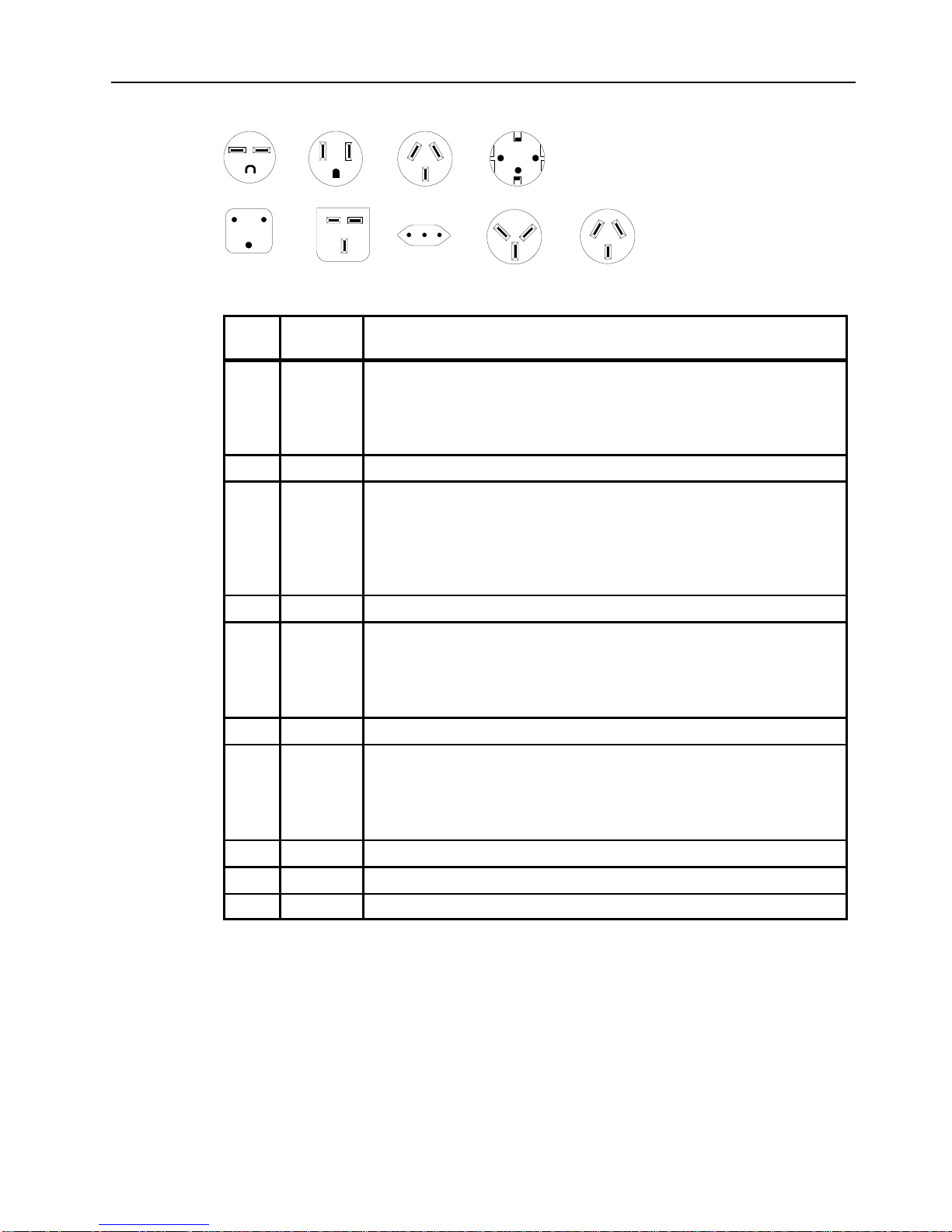
Power Cables and Plugs
1
23
4
5
6
7
89
Index
Part
Number
Country
1 14F1548 Bahamas, Barbados, Bolivia, Brazil, Canada, Costa Rica,
Dominican Republic, El Salvador, Ecuador, Guatemala, Guyana,
Haiti, Honduras, Jamaica, Japan, Netherlands Antilles, Panama,
Peru, Philippines, Taiwan, Thailand, Trinidad, Tobago, U.S.A.
(except Chicago), Venezuela
2 6427171 U.S.A. (Including Chicago)
2 6427168 Bahamas, Barbados, Bermuda, Bolivia, Brazil, Canada, Cayman
Islands, Colombia, Costa Rica, Dominican Republic, Ecuador, El
Salvador, Guatemala, Guyana, Haiti, Honduras, Jamaica, Japan,
Korea (South), Mexico, Netherlands Antilles, Nicaragua, Panama,
Peru, Philippines, Puerto Rico, Saudi Arabia, Suriname, Trinidad,
Taiwan, Venezuela
3 14F1559 Argentina, Australia, New Zealand,
4 14F1554 Abu Dhabi, Austria, Belgium, Bulgaria, Botswana, Denmark, Egypt,
Finland, France, Germany, Greece, Iceland, Indonesia, Korea
(South), Lebanon, Liechtenstein, Luxembourg, Macau, Netherlands,
Norway, Portugal, Saudi Arabia, Spain, Sudan, Sweden,
Switzerland, Turkey, Yugoslavia
5 14F1557 Bangladesh, Burma, Pakistan, South Africa, Sri Lanka
6 11H5086 Bahrain, Bermuda, Brunei, Channel Islands, Cyprus, Ghana, Hong
Kong, India, Iraq, Ireland, Jordan, Kenya, Kuwait, Malawi, Malaysia,
Nigeria, Oman, People’s Republic of China, Qatar, Sierra Leone,
Singapore, Tanzania, Uganda, United Arab Emirates (Dubai), United
Kingdom, Zambia
7 14F1560 Chile, Ethiopia, Italy
8 14F1561 Israel
9 14F1559 Paraguay, Colombia, Uruguay
Page 16

xvi Operator Guide
Page 17

Preface xvii
About This Book
This book contains information on 7013 J Series system and its operation together with a
description of the main operations that the operator may perform.
How to Use This Book
This book provides information about the operator controls, the internal and external devices
installed to the 7013 J Series system unit.
It is advisable to have one or more people beyond the system administrator be capable of:
• starting up and shutting down the system. See Chapter 2, “Using the System Unit”.
• assisting users who have problems with terminal configuration, connection, etc. See
“Terminal and Printers” in Chapter 2, “Using the System Unit”.
• operating, tape and CD-ROM units. See Chapter 2, “Using the System Unit”.
ISO 9000
ISO 9000 registered quality systems wer used in the development and manufacturing of this
product.
Related Publications
The
Problem Solving Guide and Reference
, order number SC23-2606 is the first book you
should use when you have a problem with the system unit. It contains procedures for
determining if the problem is hardware or software related.
The
7013 J Series Base Unit Hardware Setup Procedure,
order number SA23-2723
contains the procedures for the initial hardware setup of the 7013 J Series base unit.
The
7013 J Series Expansion Unit Hardware Setup Procedure,
order number SA23-2726
contains the procedures for the initial hardware setup of the 7013 J Series expansion unit.
Page 18

xviii Operator Guide
Page 19
Description of the 7013 J Series System 1-1
Chapter 1. Description of the 7013 J Series System
This chapter contains information to help you become familiar with the 7013 J Series
System.
This chapter groups miscellaneous reference information related to both the base and
expansion units.
It details the environmental specifications of the system.
In addition it shows each internal planar and card with the proper connectors and the
corresponding description, and then it shows the SCSI addresses related to both the
internal and external devices for each unit.
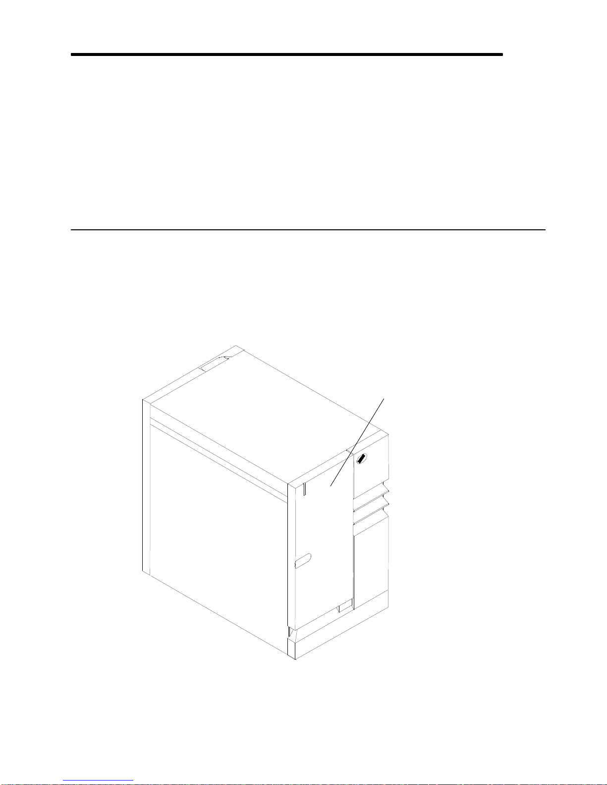
Description of the Base Unit
The 7013 J Series system is a multi-user system based on the PowerPC RISC-architecture.
It contains several types of input and output (I/O) adapters, memory, and media storage
devices. The hardware is controlled by the Operating System (OS).
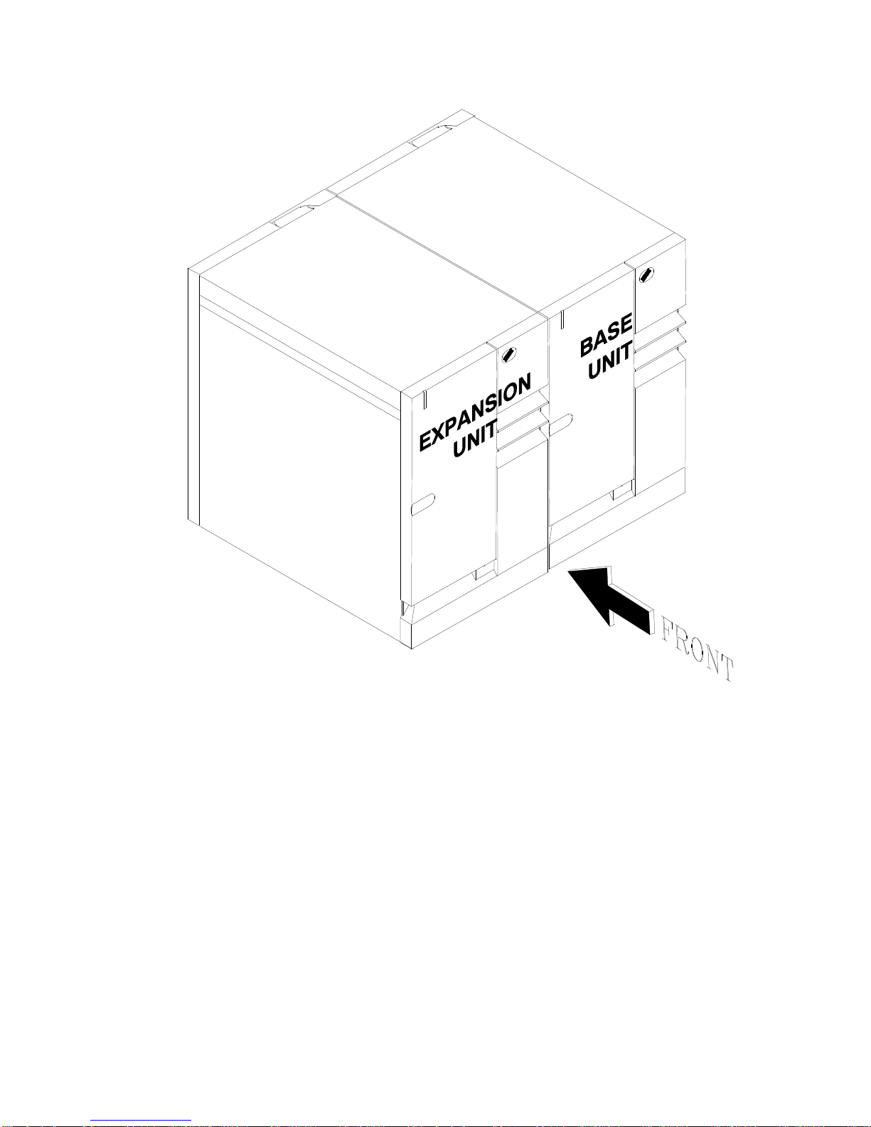
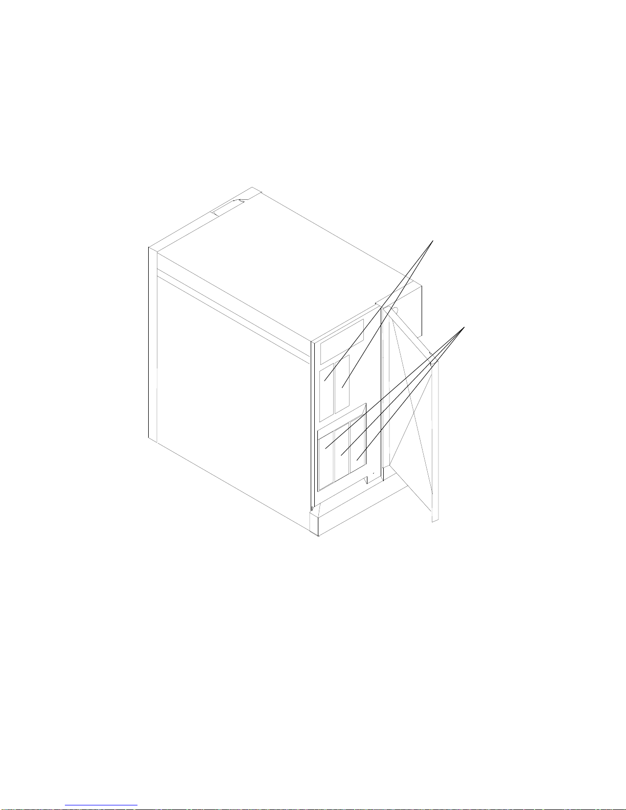
The Operator Panel is accessible behind the front door of the system.
Front Door
Front View of the Base Unit
Page 20
1-2 Operator Guide
The base unit consists of a floor standing unit, which may be expanded with the addition of
an expansion unit, positioned to the left of the base unit.
Both units have the same dimensions:
• Height: 610 mm (24.1 in.)
• Width: 360 mm (14.2 in.)
• Depth: 750 mm (29.5 in.).
Page 21
Description of the 7013 J Series System 1-3
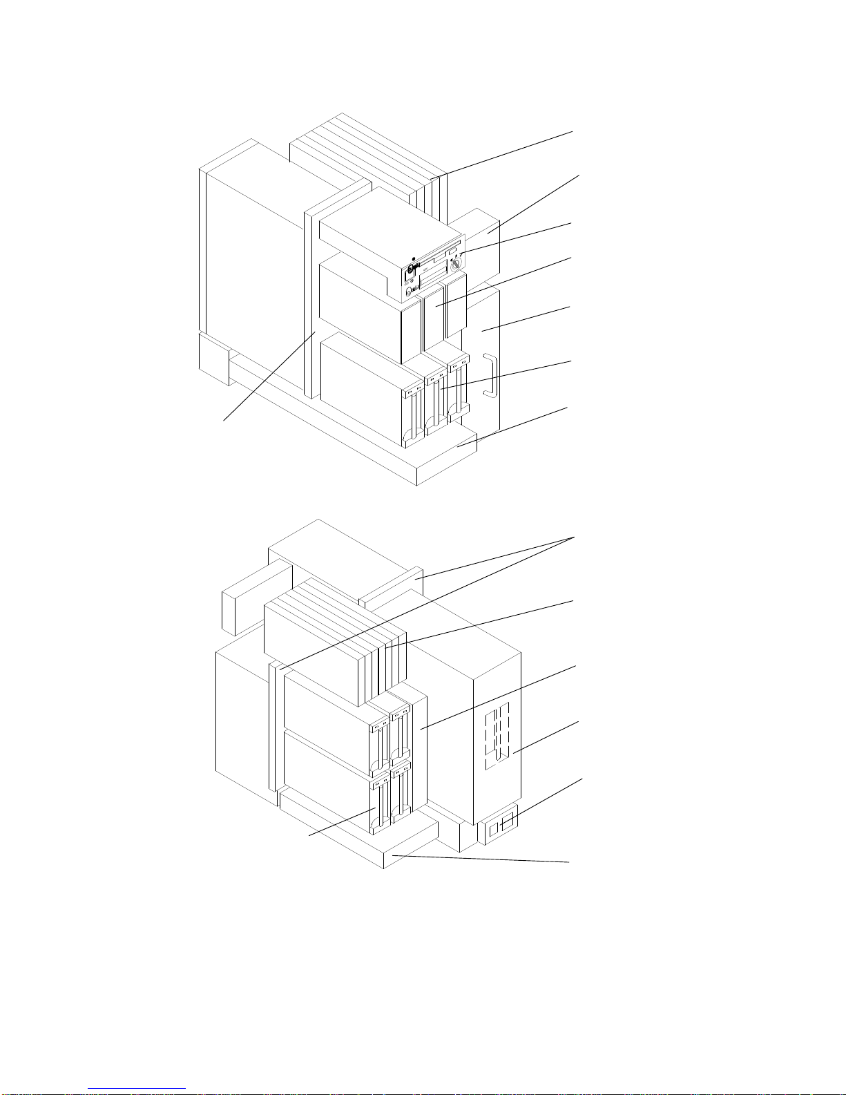
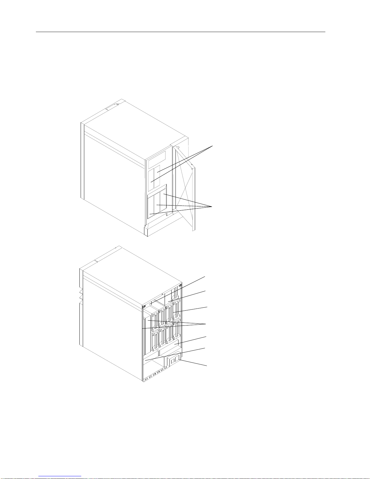
Base Unit Without Covers
The following figures show the base system unit with covers and doors removed.
Operator Panel
Micro Channel Card
Cage Fan Module
Media Devices
Power Supply
Disk Devices
Main Fan Module
Front View
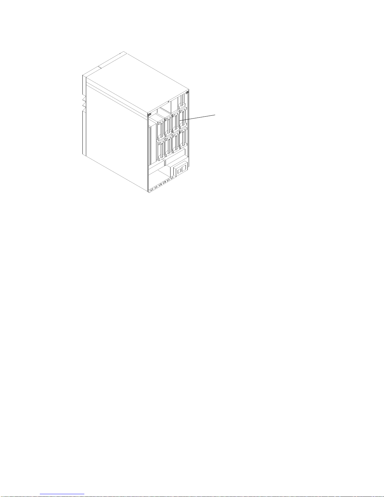
Back Plane
Micro Channel
Card Cage
Back Plane
System Interface
Board
CPU Complex
Main Power
Switch Module
Disk Fan Module
Disk Devices
Rear View
Micro Channel
Card Cage
Page 22
1-4 Operator Guide
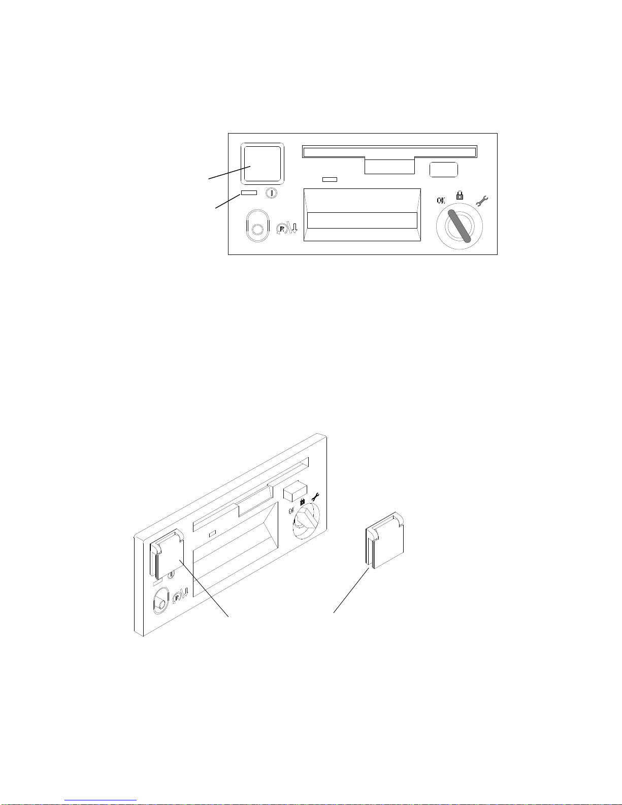
Operator Controls
The basic hardware interface between the user and the system unit, is the operator panel.
The operator panel is the primary hardware interface used by the system operator to bring
the system to an operable state. The interface with the user is provided via the system
console and/or terminal.
Power On Light
Power Button
Operator Panel with Power Controls
Power On Light Indicates that all voltages in the power supply are present and
within limits and that the fans are running. The power-on light is
used to help analyze power and cooling problems.
Power Button Controls the system power. This button enables the system to
automatically power itself back on if a power failure occurs.
The power supply has electric power as long as the power supply
cord is plugged into a working electrical outlet (even when the
power button has been pressed to turn of the system unit).
Power Button Cover This cover has been furnished as a method to prevent a person
from accidentally pressing the power button. It contains an
adhesive on the back, which enables you to attach it to the operator
panel as shown in the following diagram.
Power Button Cover
The system unit power cord must be plugged to the standard office wall outlet (1440 VA
maximum).
Page 23
Description of the 7013 J Series System 1-5
Media Devices
The SCSI interface is the main bus for the mass storage devices and is used to connect
disk drives, tapes and optical disks.
The SCSI bus internal to the unit is etched or embedded on the back plane, so it supports
device connection through direct insertion, without cables.
All the internal devices are included in a mechanical carrier that enables the devices to be
directly connected to the back plane. The carrier includes a SCSI converter board.
For the operator controls of the disk devices refer to “Using Internal Disk Drives” on page
2-47.
Base Unit
The base unit includes the basic SCSI device complex with 6 slots (SCSI bus A) and an
additional SCSI bus with 4 slots (SCSI bus B).
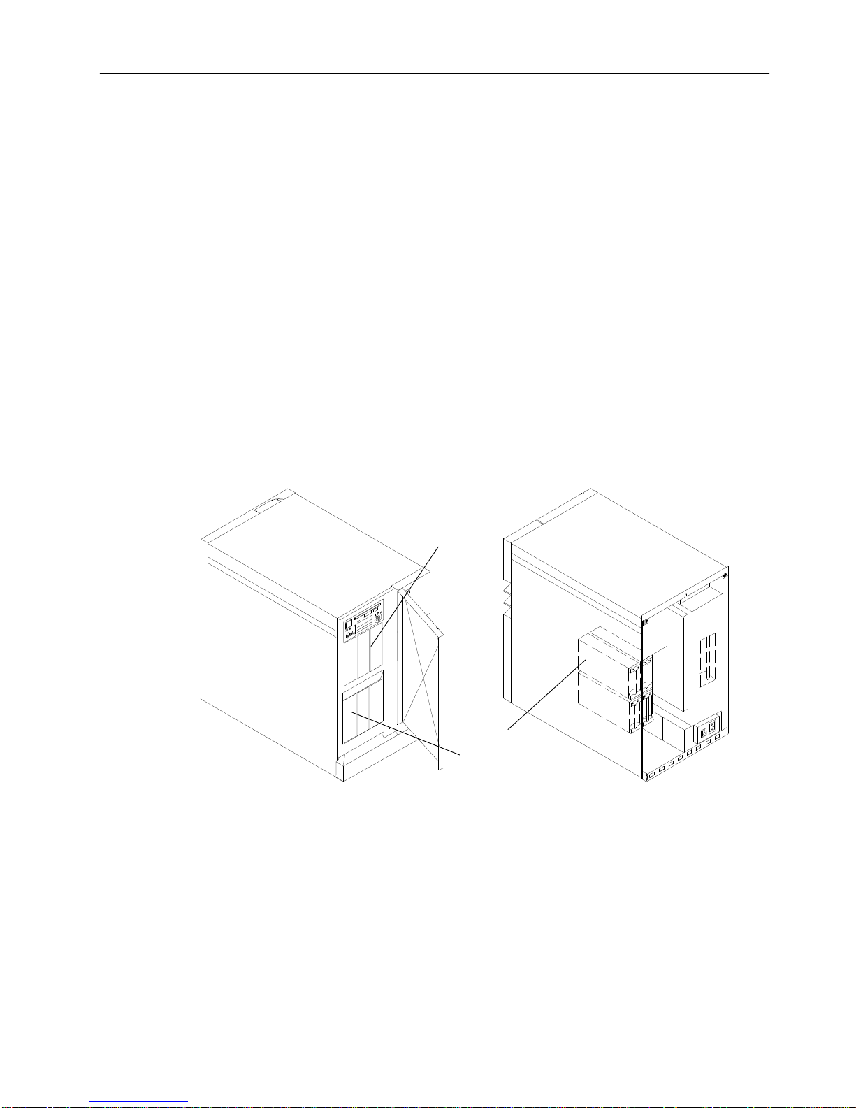
The media devices such as tape drives and CD-ROM drives are always located at the front
in the upper row of the base unit. This row can house three 5.25-inch half-high devices.
The lower device slots located at the front side are reserved for highly removable 3.5-inch
disk drives. See “Highly Removable Disks” on page 4-2, for more information about highly
removable disks.
Front View Rear View
Media
Devices
Disk
Devices
On the rear side of the system there are four 3.5-inch slots.
The disk devices connected to the slots at the rear of the unit should be accessed
only
for
maintenance or installation.
If you want to access the devices at the rear of your system unit, open the rear panel with
the operator panel key.
For more information about SCSI bus IDs and locating disk or media drives, see “Locating
a Disk or Media Drive” on page 4-4.
Page 24
1-6 Operator Guide
Description of the Expansion Unit
The expansion unit holds up to 14 Mass Storage Devices on the SCSI buses, one Micro
Channel Card Cage with eight slots, one or two System Interface Boards, one Power
Supply, and three Fan Modules.
Note: The Expansion Unit must always be positioned at the left side of the base system
unit.
Media Devices
Disk Devices
Front View
MCA Complex
System Interface Board
Main Power
Switch Module
Disk Fan Module
Disk Devices
Bulkhead SCSI
Main Fan Module
Rear View
For more information about SCSI bus IDs and locating disk or media drives, see “Locating
a Disk or Media Drive” on page 4-4.
Page 25
Description of the 7013 J Series System 1-7
Expansion Unit
The expansion unit houses a device complex with 14 device slots. The media devices (tape
drives and a CD-ROM drive) are always located in the upper row at the front side of the
expansion unit. Two optional 5.25-inch half high media devices in two 5.25-inch half high
device slots may be installed.
The lower three 3.5-inch device slots in the front are reserved for highly removable disk
drives. For more information about highly removable disks, see “Highly Removable Disks”
on page 4-2.
Media Devices
Disk Drives
Installed Devices in the Front of the Expansion Unit
Page 26
1-8 Operator Guide
Nine slots for 3.5-inch disk drives are located in the rear of the expansion unit.
Disk Drives
Installed Devices in the Rear of the Expansion Unit
A SCSI-2 Differential Fast/Wide Adapter/A is required to support the drives installed in the
expansion unit. This adapter can be either:
• installed in the MCA card cage of the expansion unit where you are installing the disk
devices.
• installed in the base unit, and connected through an external connection.
In either case a dedicated SCSI-2 Differential Fast/Wide Adapter/A supports the input of the
SCSI-2 Differential Fast/Wide Adapter/A connection to the back plane.
To support the internal storage devices in the Expansion Unit one system interface board is
required, this services the A bus. If any device is placed on the B bus of the expansion unit,
you must connect an additional system interface board.
The expansion unit has two SCSI buses.
Page 27
Description of the 7013 J Series System 1-9
Main Power Switch Module
The power system provides power and power regulation for all units of the 7013 J Series.
It enables you to power on and power off (also under operating system control) individual
units. This is particularly useful for handling power outages or to gracefully shutdown the
system in case of problems.
The power supply complex consists of:
• the Main Power Switch Module
• the Power Supply.
Each unit is equipped with one power supply capable of powering the maximum number of
devices that can be configured in a unit.
Each system unit houses one Main Power Switch Module on the rear left corner in the lower
part of the unit; this module contains the unit main breaker for the general AC power
ON/OFF control.
Attention: Before powering on the base system unit, be sure that the expansion unit main
power switch is set to on (I). If you attempt to power the base unit on when the expansion
unit is set to off (O), the power on will fail and an error code will be displayed in the operator
panel display.
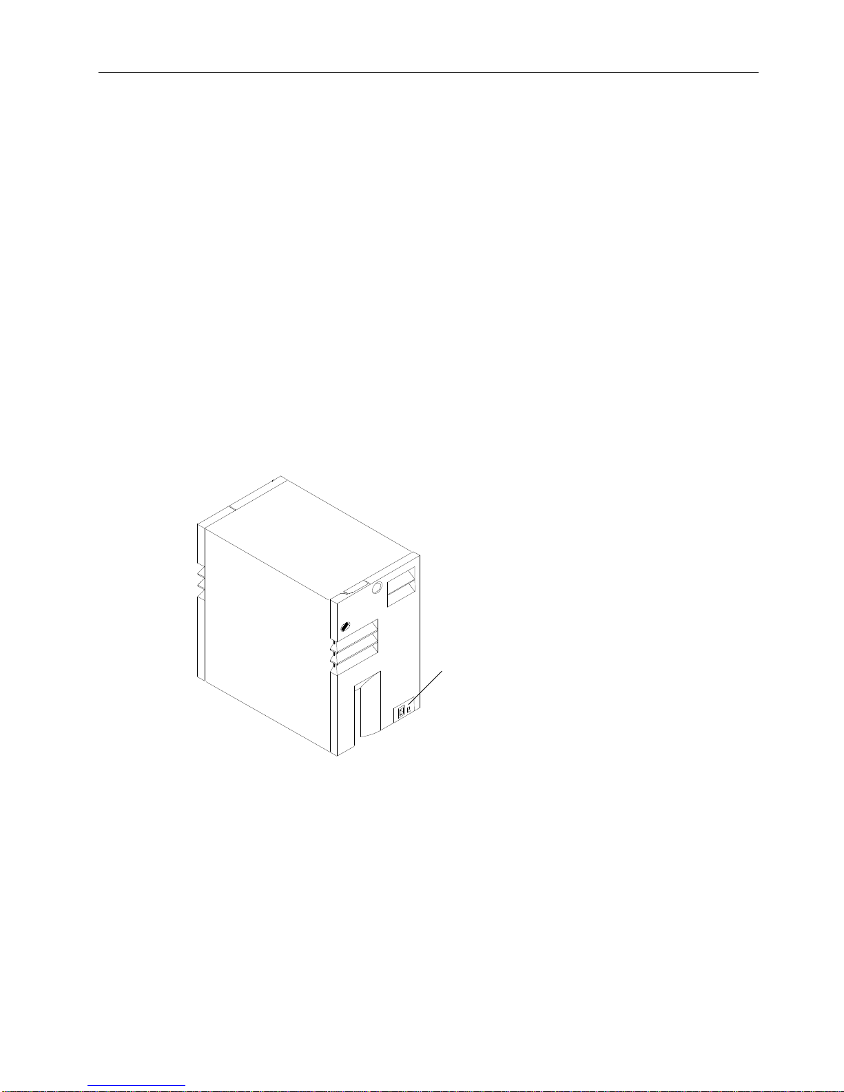
Main Power Switch
Module with System
Unit Main Switch
Rear View of Base Unit Showing Main Power Switch Module
System Unit Main Switch
Attention: Data can be lost if you use the basic unit main switch to turn off the power to the
system unit without first using an appropriate shutdown command to stop the operating
system. Refer to “Powering Down Procedure” on page 2-11 for more information about the
shutdown command.
The System Unit Main Switch at the rear of the system unit can be used to switch off power
to all the components of the system unit.
The switch has the symbols (I) for ON and (O) for OFF.
Page 28

1-10 Operator Guide
Location Codes
A location code is used to physically locate a failing device or unit. The location code is
displayed along with the service request number (SRN) when the diagnostic programs
isolate a failure. If the location code is not known, you can run the Display Previous
Diagnostic Results service aid to display the results of the last time the diagnostic programs
were run.
For more information about the location codes used in the base unit or the expansion unit,
see “Locating a Micro Channel Adapter” on page 4-3 and “Locating a Disk or Media Drive”
on page 4-4.
Location Code Format for SCSI Devices
AB - CD - EF - GH
Always 0.
Always 00.
Slot number of the SCSI controller.
00 - Internal SCSI bus connector.
01 - External SCSI bus connector of a non-integrated SCSI controller.
0S - External bus connector of an integrated SCSI controller,
SCSI address of the device.
,HHH is the logical unit number of the device shown in decimal.
Location Code Format for Non-SCSI Devices
The following example is for non-SCSI devices. These include planars, memory cards,
adapters, and async distribution boxes.
Use the example to determine the physical location of a device.
Note: The G and H fields each can contain one, two, or three characters.
AB - CD - EF - GH
Async port number or FRU location on a card or planar.
Connector number on an adapter or planar.
Slot number of the adapter, memory card, or adapter for
Always 0 on workstations.
the identified device
Always 0.
System I/O bus identifier.
Location Code Format for 7135, 9333, and 9334 Expansion Units
The location code formats for the 7135, 9333, and 9334 expansion units are described in
the publications for the 7135, 9333, and 9334 expansion units.
Page 29

Description of the 7013 J Series System 1-11
Location Code Table for SCSI and Non-SCSI Devices
Use the following table to determine the physical location of a device or unit.
Note: The location code format for 9333 devices is described on the previous page and in
9333 documentation.
Use the following example to identify these two-character pairs: AB-CD-EF-GH.
Pair
Value Description
AB 00
00
00
00
Workstation-type system unit.
CPU drawer or enclosure in a rack-type system unit.
SCSI device drawer in a rack-type system unit.
SCSI disk drawer in a rack-type system unit.
08 This is not an invalid number. Slot 8 contains a standard SCSI
adapter.
CD 00
00
00
CPU card.
MCA planar.
A device attached to the MCA planar.
01
02
03
04
05
06
07
Adapter in slot 1 of the MCA planar.
Adapter in slot 2 of the MCA planar.
Adapter in slot 3 of the MCA planar.
Adapter in slot 4 of the MCA planar.
Adapter in slot 5 of the MCA planar.
Adapter in slot 6 of the MCA planar.
Adapter in slot 7 of the MCA planar.
10
11
12
13
14
15
16
17
18
Second MCA planar.
Adapter in slot 1 of the second MCA planar or expansion cabinet.
Adapter in slot 2 of the second MCA planar or expansion cabinet.
Adapter in slot 3 of the second MCA planar or expansion cabinet.
Adapter in slot 4 of the second MCA planar or expansion cabinet.
Adapter in slot 5 of the second MCA planar or expansion cabinet.
Adapter in slot 6 of the second MCA planar or expansion cabinet.
Adapter in slot 7 of the second MCA planar or expansion cabinet.
Adapter in slot 8 of the second MCA planar or expansion cabinet.
CD 0A
0B
0C
0D
Memory card in slot A on the System planar.
Memory card in slot B on the System planar.
Memory card in slot C on the System planar.
Memory card in slot D on the System planar.
0P
0Q
0R
0S
CPU card located in slot P on the System planar.
CPU card located in slot Q on the System planar.
CPU card located in slot R on the System planar.
CPU card located in slot S on the System planar.
EF 00 Does not have a connector or software was not able to identify
the connector number.
01
02
03
04
The number of the connector on an adapter card, distribution
box, or planar. If needed, see Chapter 8 for the connector
numbering on your adapter.
0D
0E
0P
Internal diskette connector on the MCA planar.
Built-in Ethernet adapter.
Parallel printer connector.
Page 30

1-12 Operator Guide
Pair DescriptionValue
S1
S2
S3
Serial port 1 connector.
Serial port 2 connector.
Serial Port 3 connector.
11
12
13
14
21
22
23
24
Remote async node 1 on line 1.
Remote async node 2 on line 1.
Remote async node 3 on line 1.
Remote async node 4 on line 1.
Remote async node 1 on line 2.
Remote async node 2 on line 2.
Remote async node 3 on line 2.
Remote async node 4 on line 2.
GH 01
02
03
04
05
06
07
08
Memory SIMM or DIMM in location 1 on the memory card.
Memory SIMM or DIMM in location 2 on the memory card.
Memory SIMM or DIMM in location 3 on the memory card.
Memory SIMM or DIMM in location 4 on the memory card.
Memory SIMM or DIMM in location 5 on the memory card.
Memory SIMM or DIMM in location 6 on the memory card.
Memory SIMM or DIMM in location 7 on the memory card.
Memory SIMM or DIMM in location 8 on the memory card.
G,HHH 00 For devices other than those listed here
00
thru
15
Port addresses for 8-port async, 16-port async, and 16-port
concentrator distribution boxes.
01 Diskette drive 1
0,000
thru
F,255
SCSI address and logical unit number of the device shown in
decimal.
Note: When a comma appears between the G and H, digits
appearing to the right of the comma are represented in decimal.
Page 31

Description of the 7013 J Series System 1-13
Cluster Power Control
The cluster power controller (CPC) is an external option which provides:
• Connectivity between a remote support facility and multiple CPUs through a modem
• Connectivity from any attached CPU to any disk drive drawer
• Central power-on and power-off through the TTY.
The CPC provides ports for connection of multiple 7012 G Series system units, 7013 J
Series system units, and 7015 Model R30, R40, and R50 CPU enclosures for interface
connection of CPUs and disk drive drawers. The CPC also contains ports for connection of a
modem and TTY.
For more information about the CPC, refer to
Cluster Power Control Operator and Service
Guide
, order number SA23-2766.
Disk Drive Connectors
(PCI Connectors)
Disk Drive Connectors
(RS485 Connectors)
CPU
Connectors
CPU D
CPU C
CPU B
CPU A
1
2
1
2
1
2
1
2
CPC
Expansion
Connectors
CPC
Left
CPC
Right
1
2
1
2
TTY Connector
Modem Connector
Page 32

1-14 Operator Guide
Page 33

Using the System Unit 2-1
Chapter 2. Using the System Unit
This chapter explains how to use the operator panel and other devices for control, input,
display, and data storage in the 7013 J Series system unit.
CAUTION:
This product is equipped with a three-wire power cable and plug for the user’s
safety. Use this power cable in conjunction with a properly grounded electrical outlet
to avoid electrical shock.
Main Power Switch Module
Each system unit is equipped with a Main Power Switch Module containing the switch for
general AC power ON/OFF control, and the AC power cable connector.
Before performing the first startup of the machine being installed, the following steps must
be performed to give it AC power. Please note that this procedure must be repeated for
each system unit (expansion and base).
1. Press the Main Power Switch at the rear of each unit to the Off position “O”.
2. Connect the power cord connector to the connector present on the Main Power Switch
Module of the units, as shown in the figure.
Main Power Switch
Module with Power
Cord Connector
Page 34

2-2 Operator Guide
3. Plug the power cords into the elelectical outlet.
4. Perform this step first on the expansion unit if there is one attached. Press the switch
located on the Main Power Switch Module to on, switching it to the ”I” position.
Main Power
Switch
Page 35

Using the System Unit 2-3
The Operator Panel
The Operator Panel complex is installed on the front of the main unit. To access the
operator panel you have to open the front door.
The Operator Panel elements are controlled by the CPU and by a special microprocessor
located on the I/O card called SystemGuard.
Operator Controls
Operator Panel Display
Reset/Scroll
Button
Key Mode Switch
Power Light
Power Button
Diskette Drive
Normal
Secure
Service
Power Button Used to switch the power to the system on or off
Power Light Green LED: when lit, indicates all voltages in the power supply
are present and within specified limits and all fans are running.
The power-on light is also used to help analyze power and
cooling problems.
Reset/Scroll Button Used to reset the system unit, depending on the position of the
key mode switch. Also used to scroll the messages on the
Operator Panel Display.
Operator Panel Display Displays status indication of the system
Key Mode Switch Is a key controlled switch with three positions labeled:
, and .
Diskette Drive Used to read and write diskettes
The key mode switch functions are enabled only when power is present in the base unit,
that is, the base unit main power switch on the back of the unit is in the ON position.
Page 36

2-4 Operator Guide
Reading the Operator Panel Display
Attention: If you have a flashing 888 in the Operator Panel Display, do not push the
Reset/Scroll button before you carefully read the related documentation.
The Operator Panel Display has two 16 position rows. The display is used for:
• Event indications and problem reporting during Power-On-Self-Test (POST) and
Configuration Methods.
• Progress and command indications when loading diagnostics.
• Event indications during diagnostics when a Console-Display is not available.
• Problem reporting during diagnostics when a Console-Display is not available.
• Check Stop indications when the machine cannot recover from a Check Stop.
• Crash reporting when the machine cannot recover from a crash.
• Dump progress and command indications during dump.
• Problem reporting when there is a power problem.
During the POST, the numbers displayed indicate the progress of the testing. If an error that
requires attention is detected, the system unit stops and a flashing 888 is displayed in the
Operator Panel Display to identify the error.
When the self-tests and configuration methods complete without error, the display is blank.
Operator Panel Display
Please refer to the
Problem Solving Guide and Reference
for a detailed description of what
is displayed on the operator panel display.
Page 37

Using the System Unit 2-5
Using the Reset/Scroll Button
Attention: When the mode switch is in Normal or Service position, pressing the
Reset/Scroll button causes the unit to reset and do an IPL (Initial Program Load). Pressing
the Reset/Scroll button while the operating system is running can result in damaged or lost
data.
The Reset/Scroll button is used to:
• Reset the system unit and cause a boot when the mode switch is set to Normal or
Service. Pushing the Reset button once may cause an incomplete reset and the system
may not restart. Therefore it is recommended to push the reset button twice for a
complete reset.
• Read out messages (scroll) after a flashing 888 is displayed.
• Start the dump program when a manual dump is needed.
• Sequentially read system configuration in Stand-By Mode and with the key mode switch
in Service position.
Pushing the Reset button once causes an incomplete reset and the system may not restart.
Therefore it is recommended that you push it twice for a complete reset.
When the mode switch is in the Secure position, the Reset/Scroll button is disabled.
Reset/Scroll Button
Page 38

2-6 Operator Guide
Setting the Key Mode Switch
The key mode switch has three positions:
Normal Position
Secure Position
Service Position
The switch is used to establish the initial program load (IPL) path. The IPL loads the system
programs, checks the system hardware and prepares the system for user operation.
Before starting the system unit for normal day-to-day-operation, set the key mode switch to
the normal position. This permits the operating system to load after the power-on-self-tests
(POST’s) are completed.
Note: It is possible to set the Electronic Mode Switch (E-Key) through SystemGuard
firmware from the local or remote SystemGuard BUMP console. In Normal mode an
electronic key may be used to set Normal, Secure and Service modes. For remote
maintenance, see “Electronic Mode Switch” page 2-8. In Secure and Service
modes, the physical key setting prevails.
Operator Panel with Key Mode Switch in Normal Position
Key Mode Switch
The following table summarizes the possible operations for each key mode switch position:
Operation Key Mode Switch Position
Normal Secure Service
Reset Enabled Disabled Enabled
BUMP Console Active Enabled Enabled Enabled
BUMP Console Debug/
Dump
Disabled Disabled Enabled
Normal IPL Enabled Disabled Disabled
Service IPL Disabled Disabled Enabled
Note: In this information, the name SystemGuard BUMP Console refers to the Local
Console connected to the S1 port on the system interface board.
Page 39

Using the System Unit 2-7
The following list explains the uses of the key mode switch positions:
Attention: The Reset/Scroll button is active when the mode switch is in the Normal or
Service position, and pressing the Reset/Scroll button can cause data to be damaged or lost
if the operating system is still running.
OK The Normal Position is used for attended operation, which is the usual or
normal placement of the key mode switch when an operator is present and
in control of the operation of the system unit. The Reset/Scroll button is
active when the key mode switch is in the Normal position. The IPL
proceeds according to the Normal Mode Bootlist.
The Secure position prevents the system from booting. If the system is
already booted, this position does not lock the system console or block
system network communication. It also prevents an autoboot in case of a
system crash or checkstop condition.
When the operating system is up, turning the key to the Secure position
disables the Reset/Scroll button. With the key mode switch in this position,
a passerby cannot accidentally press the Reset/Scroll button and cause a
loss of data.
The Service position is used for attended operation when hardware or
software service is conducted. The Service position activates operating
system console sequences that support error determination (debug) and
storage printout (dump). In the Service position, the system unit attempts to
IPL from the media drive. The IPL proceeds according to the Service Mode
Bootlist.
The key mode switch is also used for the following:
• To indicate to the diagnostic programs that there is no console available. This is
done by setting the key mode switch from Service to Normal and then back to Service
when a c31 is displayed on the operator panel display.
• To start a dump. If the system is booted in Normal mode, a manual dump is started with
the key mode switch set to Service and pressing the Reset/Scroll button. If the system is
booted with the key mode switch set to the Service mode, a dump is started by setting
the key mode switch to Normal and pressing the Reset/Scroll button. If the Reset/Scroll
button is pressed twice, the system reboots.
If there is a problem with the system unit, refer to
the
Problem Solving Guide and Reference
before setting the mode switch to the Service position or pressing the Reset/Scroll button.
Attention: Do not set the key mode switch from Normal (OK) to Service while the system is
booting. Instead, wait until the boot is completed and then change the mode switch setting.
Page 40

2-8 Operator Guide
Electronic Mode Switch
The electronic mode switch (E-key) enables you to remotely change the status of the key
mode switch and:
• places the system for maintenance or debug purpose from a remote location, from
Normal to Service mode, without a person physically being present near the system to
change the key mode switch position,
• assists remote access and service of a customer installed machine from a central
customer hub (CH) or IBM service center and to run off-line and online diagnostics from a
remote location to isolate a problem to the FRU level,
• activates from an enabled terminal (via a software command) the use of the maintenance
features on the remote line
• breaks a remote maintenance session by the service people, if some intrusion attempt is
suspected
• prevents non-authorized access to the system setting the system in Secure mode.
The Electronic Mode Switch has validity only when the operator panel key mode switch is
set to the Normal position. It is able to electronically move the position of the ”key mode
switch” on the operator panel in the following way:
Key Mode
Switch
Electronic
Mode Switch
Status of the System (*)
Normal Normal Normal
Service Service
Secure Secure
Secure Set to any mode Secure
Service Set to any mode Service
Note: (*) The status of the system matters only during IPL and in off-line maintenance
mode; once the Operating System is up and running, the key mode status is
relavent only for maintenance application software and diagnostic aids.
The following functions of the key mode switch cannot be performed remotely by setting the
E-Key:
• Indicate to the diagnostic program that no console is available
• Start a manual dump.
See the
AIX Version 4 System Management Guide: Communications and Networks
and the
keycfg command for detailed information on the electronic mode switch.
Setting the Electronic Mode Switch (E-Key)
See “How to Set the Electronic Key” on page 3-39 for information about setting the
electronic key mode switch.
Page 41

Using the System Unit 2-9
Starting and Stopping the System Unit
Note: This section presents an overview of the procedures to follow when starting up and
shutting down the system. Before performing initial start up procedures, check with
the system administrator to determine if the system operating software has been
loaded and define the best startup and shut down procedures for the system. If the
system operating software must be loaded, refer to the
AIX Version 4 System
Management Guide: Operating System and Devices
.
Methods of Starting the System Unit
The four methods of starting the system unit are as follows:
Manually The power is switched on manually, and the
system unit does a normal or a service IPL
depending on the mode switch position. For further
explanation refer to page 2-10.
Remotely The power is switched on from another location,
and the system unit does a normal IPL. To use this
method, a modem or an equivalent device must be
attached to the system.
Programmed by date and time On a specific day and time, the power is switched
on and the system unit does a normal IPL. This
facility is available only with the system in stand-by
mode.
Recovery after a power failure When the power is restored, the power is switched
on and the system unit does a normal IPL.
The examples used in this section describe a manual start up procedure. Refer to the
AIX Version 4 System Management Guide: Operating System and Devices
, for more
information on all start up and shut down procedures. Also refer to “Chapter 3. Using
System Guard” and “Appendix G. System Power States” for additional start up and shut
down procedures.
When you press the power button, the power light comes on and the system starts its
power-on self-tests (POST). During the POST, messages warning that these tests are in
progress are displayed in the operator panel display. If an irrecoverable error occurs, its
error code is displayed in the operator panel display.
Page 42

2-10 Operator Guide
Manually Starting the System Unit
1. Set the power switches of the external devices to On (if connected).
2. If an expansion unit is attached, set the main power switch on the back of the unit to On.
Set the base unit main power switch at the rear side of the system to On.
3. The LCD display will display the message “Stand-By”, indicating that stand-by power is
turned on.
4. With the key mode switch in Normal or Service position, start the system unit by
pressing the Power button located on the operator panel. The green led lights up and the
system comes on.
Power Button
Key Mode Switch in
Normal Position
Note: If the power button is already pushed in, you must press it once to reset the button,
and then press it again to turn the power on.
The power on tests may run for several minutes with 165 showing on the operator panel
display. If you have the SystemGuard console enabled, you can monitor the progress of the
power-on (PON) test portion of the IPL process.
Wait until the Login message appears on the terminal; at this point, the system is ready to
work.
Note: If the green led does not light up and the power does not come on, ensure that the
power cord at the back of the system is plugged into a grounded electrical wall outlet
and that the system unit main switch is in the On position. Refer to “Appendix G.
System Power States” for a more detailed description of the system power states. If
this does not solve the problem, refer to the
Problem Solving Guide and Reference
.
Page 43

Using the System Unit 2-11
Manually Stopping the System Unit
Attention: Use the shutdown command to stop the system unit; loss of data can occur if
this command is not used.
1. Ensure that the Key Mode switch is in Normal or Service Position.
Note: It is possible to run the shutdown procedure from the system console (local or
remote line) with the key mode switch set to the Secure position. Set the key mode
switch to Normal or Service position before rebooting the system.
Key Mode Switch in
Normal Position
2. Perform the following Powering Down procedure.
Powering Down Procedure
The system should not be powered down before the operating system has stopped. The
following three steps must be followed to shut down the system.
Note: It is possible to run the shutdown procedure from the system console (local or
remote line) with the key mode switch set to the Secure position. Set the key mode
switch to Normal or Service position before rebooting the system.
1. Ensure that the key mode switch is in Normal or Service position
Note: You can run the shutdown command only if you are logged onto the system as root
user.
2. Run the shutdown command.
When the shutdown program is run, a warning message will be sent to all connected
terminals. The user can specify the time period between the sending of the warning
message and the system shutdown. This time is given with a default of 60 seconds.
shutdown –h +5
represents a period of 5 minutes
Attention: This period should allow enough time to finish your session and save your data.
The amount of time can vary from a few seconds, enabling the user to exit the vi editor, for
example, to several minutes, allowing you to properly finish the update of a database. If you
are updating a database, if the system is shut down before you have properly finished your
update session, the integrity of the database can be negatively affected and there can be
loss of important data.
The display of the message halt completed indicates the procedure is ended.
Note: In Standby-mode you can prevent unauthorized access to the system by turning the
key mode switch to the Secure position.
3. To complete the power-off procedure, turn the key mode switch to the Secure position;
set the power switch (located both on the system console and on the other terminals) to
Page 44

2-12 Operator Guide
Off, and push the Power button on the system unit operator panel to set it to the off
position..
To Turn Power Completely Off
Attention: Unpredictable results can occur that effect your data files if you use this method
to stop the system unit.
1. To switch the power to the system completely off, set the system unit main switch on the
rear side of each unit (base and expansion) to off.
2. Set the power switches of the external devices to Off.
General Information about Multiple Systems
If your system is attached to another system, certain actions performed by an operator can
affect either one or both systems, and these actions can require further consideration before
any changes are made. Some actions requiring further consideration are:
1. Starting and stopping the communication with other system
2. Running diagnostics on one of the systems
3. Analyzing the error log information
4. Installing adapters or devices on one of the systems
5. Using the wrap plugs with the diagnostics.
When the system unit is attached to another system, make sure you isolate this system unit
before stopping the operating system or running diagnostic programs. Some system cabling
changes (such as installing wrap plugs or removing a device from the configuration) can
require the operator to perform an action on the attached system before making the change.
Refer to the
Diagnostic Information For Micro Channel Bus Systems
for more information on
this subject.
Page 45

Using the System Unit 2-13
Terminals and Printers
Several terminals and printers can be connected to the system. All information concerning
their technical characteristics and setup is contained in
AIX Version 4 System Management
Guide: Operating System and Devices.
System Consoles
In 7013 J Series systems two RS-232 lines on the system interface board can be reserved
for the maintenance environment. The connection to the system can be done directly (local
line) or via a modem and a dedicated leased line or a dial-up switched phone line (remote
line). If the maintenance is not enabled, these two lines can be addressed as normal tty
lines.
If the maintenance feature is enabled, the two system consoles are defined, depending on
which port on the system interface board the console is connected to, as follows:
BUMP Console refers to the terminal connected to the S1 port of the system
interface board and is normally used as system console. This
console can be a local terminal or a remote terminal or terminal
emulator in the customer hub center. If the related flag to control
the maintenance environment is properly set, the BUMP console
allows the use of off-line maintenance features.
Service Console is connected to the S2 port of the system interface board. When
the related flags to control the maintenance environment are
properly set, it enables the remote operator (IBM service center) to
perform maintenance and AIX commands in every system condition
(stand-by, init-time and run-time) as well as the local operator does
from the BUMP Console.
If there is a system problem, the S2 line is able to perform a dial-out function, which sends
an error message to the service center, enabling the remote operator to isolate the system
problem.
During a remote connection both the BUMP console and the service console have control of
the system, each one becoming an echo copier of the other. This condition permits the local
operator to control the remote operator for security reasons. The local operator (customer)
can interrupt the connection established by the remote operator either locally by setting the
key mode switch to Normal or Secure, or remotely through an escape sequence to change
the state of the E-key (if the key mode switch is set to Normal and the E-key is set to
Service).
If neither the S1 nor the S2 line are configured as BUMP lines, the Maintenance menu is not
available on these lines. In this case a limited maintenance menu is provided in Stand-by
phase (main power off, only BUMP is alive). This menu is protected by a keyword and is
available only to service people.
Page 46

2-14 Operator Guide
Using Internal Mass Storage Devices
The internal mass storage devices include the media devices like the diskette drive, tape
drives and CD-ROM-2 drive and all the disk devices. After a general description on the
special capability called Hot Removability, which is valid for the media and the disk devices,
this section gives a detailed description about operator controls and how to work with the
media devices and the disk devices.
The following devices can be installed in your 7013 J Series system unit:
• an 8 mm helical scan tape drive
• a 1/4 Inch QIC cartridge streaming tape drive
• a 4 mm DAT tape drive
• a CD-ROM-2 drive to support optical disks.
The operator panel contains a 3.5-inch diskette drive.
Media Devices
Diskette Drive
Media Device Locations in the Base Unit
Note: For information about media device locations for the expansion units, see page 1-7.
For more information about locations of the disk devices and media devices, see page 1-3.
Page 47

Using the System Unit 2-15
Using the 8 mm Tape Drive
Internal magnetic tape drives are typically used as back-up drives.
The 8 mm helical scan has the following characteristics:
• capacity 5/10GB
• media data transfer 500KB/sec
• Capability to read and write 7G bytes cartridges (14G bytes with compression)
• Form Factor 5 1/4 Inch Half Size
• read/write compatibility with 2.3GB format
Functions
The 5GB 8 mm tape drive has two green status lights and one amber status light. The on/off
combinations of the status light indicate the conditions of the 8 mm tape drive.
Green
Amber
Status Lights
Green
Unload Button
Drive Door
8 mm Tape Drive Operator Controls
Each of the ISO symbols located next to a status light indicates a specific condition of the
tape drive as follows:
Disturbance (amber status light)
Ready (green status light)
Busy (green status light)
Page 48

2-16 Operator Guide
Status Lights
The following table explains the meaning of the green and amber status lights.
Disturbance
Ready Busy What has occurred:
On On On The power-on self-test (POST) is running
or the system has issued a Reset to the
drive.
Off Off Off One of the following has occurred:
• The power is off
• The POST has completed
successfully, but no tape cartridge
has been inserted.
Off Off Flashing A tape cartridge has been inserted and
the 8 mm tape drive is performing a tape
load/unload operation.
Off On Off A tape cartridge has been inserted and
the 8 mm tape drive is ready to receive
commands
Off On Flashing The tape is in motion and the 8 mm tape
drive is busy running a device operation
Flashing Off Off The 8 mm tape drive has detected an in-
ternal error that requires corrective action.
On Off or On Off or Flashing The tape path requires cleaning
Note: If an error condition occurs, first try to recover by pressing the unload button. If the
condition continues, call your service representative.
General Information for 5.0GB 8 mm Tape Drives
• Use only “Data Grade” 8 mm tape cartridges. These cartridges are identified by either a
“Data”, “D” or “D8” marking on the data cartridge.
• Remove the tape cartridge from the tape drive when it is not used, and store the cartridge
vertically in the cartridge case.
• Do not attempt to open the door on the data tape cartridge. This door covers and
protects the magnetic tape material from dirt, dust and damage.
• Avoid touching the tape because this can cause loss of data.
• Keep the drive door closed except when loading or unloading a cartridge.
• Back up and then discard any tape cartridge that repeatedly produces error messages.
The error information is in the system error log.
• Clean the tape path regularly according to the cleaning procedure of the 8 mm tape drive.
Use only recommended cleaning cartridges; other cleaning cartridges can permanently
damage your 8 mm tape drive.
• If the cartridge has been stored in an environment different from the drive, the cartridge
must be acclimated to the new environment before use. Follow the instructions included
with each new cartridge.
Attention: Do not use video grade cartridges in the 8 mm tape drive. Video grade tapes can
be unreliable and may cause permanent damage to the 8 mm tape drive.
Page 49

Using the System Unit 2-17
Setting the Write-Protect Tab on 8 mm Tape Cartridges
Setting the write-protect tab on a tape cartridge is necessary so that information is not
accidentally lost. When the write-protect tab of a tape cartridge is set (window closed),
information can be read from the tape, but cannot be written to it.
The window on the tape cartridge controls write-protection as follows:
Window
Closed
Window
Opened
Tape is Write-Protected
Tape is NOT Write-Protected
Performance
The 8 mm tape drive employs sophisticated error recovery techniques to protect your
valuable data. When the drive reports an irrecoverable error, it has reached a point where
further retries may only damage the tape and other actions must be taken.
Under the best of conditions, an irrecoverable data error should occur no more frequently
than once every 4 years on a drive, assuming a 1GB back up 6 times a week. However,
tape cartridges that have been damaged, exposed to environmental conditions outside of
the recommended range, or worn out can greatly increase the frequency of irrecoverable
data errors.
Also, a drive that has not been regularly cleaned or that is worn out can contribute errors.
The environment that the drive and media operate in is a major contributor to the reliability
of the recorded data. A good environment will enhance the reliability, while an environment
that does not comply with the recommended limits may cause lost saves and damaged
media to occur.
It is possible, however, to have other influences (power surges, or a dust particle, for
example) which cause a transient error that cannot be duplicated. Such transient errors
should be very infrequent, and repeated occurrences should be further investigated to
locate the cause.
Usage
For those customers with more than one computer system, the 8 mm tape drive is designed
to support data interchange between systems. However, transporting the cartridge between
two systems not within the same environment could cause permanent damage to the
cartridge and resulting loss of data if precautions are not observed.
These precautions include:
• Careful handling
• Proper position of the cartridge (it should be kept on its edge)
• Always keeping it within its clear plastic dust cover
• The environmental limits recommended for the media should not be exceeded.
If the cartridge has been stored in an environment different from the drive, the cartridge
must be acclimated to the new environment before use. Follow the instructions included
with each new cartridge.
Page 50

2-18 Operator Guide
Loading the 8 mm Tape Cartridge
Before loading the tape cartridge, make sure the power is on and the write-protect switch on
the tape cartridge is properly set.
The tape drive loads the tape from the cartridge and prepares it for reading and writing.
Grasp the edges of the 8 mm tape cartridge with the write-protect switch towards you and
the window side of the cartridge towards your left.
Slide the tape cartridge into the opening on the front of the 8 mm tape drive until the loading
mechanism pulls the cartridge into the drive and the drive door closes. The ready status
light (green) will go on if the load operation was successful.
Write-Protect Tab
Ready Status Light
(Green)
8 mm Tape Cartridge
Window Side of
Tape Cartridge
The tape takes about 25 seconds to load. When the green light comes on, the drive is ready
for data operations.
Commands can be entered while the tape is loading. Any commands to the tape drive start
running once the tape has finished loading. Commands not requiring the tape cartridge will
run immediately.
Page 51

Using the System Unit 2-19
Unloading the 8 mm Tape Cartridge
Push the unload button. The drive will rewind the tape within the cartridge and ejects the
cartridge from the drive opening.
The time required for a tape to rewind and unload is between 18 seconds and 3 minutes,
depending on the position of the tape when the unload button is pushed.
If the tape cartridge cannot unload and has to be removed manually from the drive, contact
your service representative.
Page 52

2-20 Operator Guide
Types of 8 mm Tape Cartridges
Test Tape Cartridge Only use this
specially labeled
tape cartridge (found in the
media kit with the 8 mm tape drive) to check out the operation
of the drive or when running diagnostics. Do not use it to save
programs or data.
Data Tape Cartridge Use this
non-labeled
cartridge for saving your programs or
data. There is a data tape cartridge in the media kit to help
start your tape operations immediately. Later, if you order
additional cartridges, they are shipped five to a package. Each
tape cartridge provides up to 5/10GB of storage. Any
cartridges you use must be compatible for use in this tape
drive and certified for data applications.
Cleaning Tape Cartridge Be sure to observe all of the instructions that come with the
cleaning cartridge. Use this cartridge to clean the tape paths
of the 8 mm tape drive. Discard this cartridge after it has been
used 12 times. Additional cleaning cartridges can be ordered.
Refer to the “Preventive Maintenance ”section for more
details.
Preventive Maintenance
There are some simple preventive maintenance operations which should be performed
periodically, to ensure the correct functioning of the system and its devices. Particular care
should be taken in using devices such us streamer and tape devices, to ensure their
efficiency and avoid data loss problems.
This section contains the description of these maintenance operations.
Cleaning the Tape Path on the 5GB 8 mm Tape Drive
Attention: Do not use video cleaning cartridges in the 8 mm tape drive. Video cleaning
cartridges can damage the 8 mm tape drive. Some video cleaning cartridges are extremely
abrasive. An 8 mm tape drive may be permanently damaged after only a few cleaning
operations using an abrasive-type cleaning cartridge.
The 8 mm tape path should be cleaned either approximately every 30 hours of tape motion
or once a month. The 5GB 8 mm tape drive counts the number of hours of tape motion and
indicates when the tape path requires cleaning when the lighted disturbance status light
(amber) is on.
More frequent cleaning may be required if the drive is operated in a dusty environment or in
humid conditions. If dust is allowed to accumulate, the drive has to perform more reads and
writes. This can cause a loss of data and may be prevented by regularly scheduled cleaning
of the drive.
The cleaning cartridge cleans the drive up to 12 times before to be discarded. If you attempt
to use an 8 mm cleaning cartridge more than 12 times, the tape drive automatically detects
the error and ejects the cleaning cartridge with the disturbance status light (
amber)
remaining on.
Before loading the 8 mm cleaning cartridge, make sure the power to the 8 mm tape drive is
on.
Page 53

Using the System Unit 2-21
Loading the 8 mm Cleaning Cartridge
1. Grasp the edges of the 8 mm cleaning cartridge with the window side of the cartridge on
your left.
2. Slide the cleaning cartridge into the opening of the front of the 8 mm tape drive until the
loading mechanism pulls the cartridge into the drive.
Window Side of
Cleaning
Cartridge
8 mm Cleaning Cartridge
Disturbance Status
Light (Amber)
Loading the 8 mm Cleaning Cartridge
3. After the 8 mm cleaning cartridge has been fully inserted into the 8 mm tape drive, the
following cleaning operations are performed automatically:
– The cleaning tape is loaded into the tape path.
– The drive is cleaned by moving the cleaning tape forward for approximately two
minutes.
– The tape is unloaded and the cleaning cartridge is ejected from the tape drive when
the cleaning operation is complete.
A successful cleaning operation is indicated when the disturbance status light (
amber)
goes off.
Tape Handling
When loading a tape in the drive, the cartridge should be removed from the case very close
to the front panel of the drive to reduce accumulation of airborne dust and dirt particles. The
same process should be followed when removing the tape from the drive.
Do not permit smoking near the tape drive, as smoke particles can cause data errors.
Don’t use excessive force when inserting or removing the cartridge from the drive. If it
seems to be hung up, gently repeat the load or unload process.
If the cartridge is placed inside a briefcase, and in such a way kept from moving around, it
may be possible to safely transport it through hostile environments.
The case should be carried out directly to the storage area and not be exposed too long
periods of high or low temperatures.
Page 54

2-22 Operator Guide
It must never be left in a car window, where sunshine can rapidly heat the air, and never left
in a car overnight.
It should be noted that airport-style metal detectors and hand held scanners will not affect
the data stored on the 8 mm tape.
8mm Data Cartridge should be stored vertically and in the supplied case.
• Recommended Operating Environment:
– 5°C to 40°C
– Relative Humidity 20% to 80% non condensing
– Max Wet Bulb to 26°C
• Recommended Storage Environment:
– Temperature 15°C to 25°C
– Relative Humidity 40% to 60% non condensing
Note: Before using a data cartridge, allow it to acclimate to the operating environment (24
hours or the amount of time it has been exposed to dissimilar conditions).
Archive Life
If proper storage conditions are maintained, quality 8 mm tapes can have a recorded data
archive life of over 30 years:
• Use tapes with 4 to 20 passes on them. In the first few passes, new tapes shake off or
shed excess magnetic media and binder deposited during the tape manufacturing
process. These can result in higher soft error rates during the first few passes.
• Pre-condition the tapes:
– Write/Read tape to measure error statistics (from LBOT to LEOT)
– Do this a minimum of 4 passes and a maximum of 20 passes
– Do this on a known good drive
– Physically examine tape pack winding for quality wind
– Use only tapes that have temperature stabilized.
• Maintain constant environment:
– Best environment is 18C (65F) at 40% RH
– Control environment while transporting tapes
– Ensure no chemical conditions exist
– No dust
– Have positive pressure air.
• Long Time Archiving Conditions:
– 5°C to 32°C
– 20% to 60% RH (non condensing)
– Wet bulb 26°C maximum
• Local Archiving Conditions Range:
– 18°C to 40°C
– 40% to 60% RH (non condensing)
• Store on edge in their protective enclosures and don’t stack anything on top of them.
Page 55

Using the System Unit 2-23
• Keep the drive clean.
• Store data in a streaming (not Start/Stop) mode. Run the tape from BOT to EOT at
normal speed.
• Exercise the tapes once every 12 months by reading the entire tape, to remove any
stress which has built up in the tape pack during the storage interval. This interval can be
lessened at lower temperature conditions, and should be increased at higher temperature
conditions.
Page 56

2-24 Operator Guide
General Information for 4.0GB 4 mm Tape Drive
The 4.0GB 4 mm tape drive is an internal streaming tape drive that is used to:
• Save and restore system data files.
• Archive important records.
• Distribute operating system software upgrades.
The 4 mm tape drive is designed to be attached to any system using a single-ended
interface meeting the Small Computer System Interface ll (SCSI-ll) Standard ANSI
X3.131-199X Rev . 10h.
The 4 mm tape drive has the following features:
• Capacity of 4.0GB per cartridge. 8GB is typical with data compression and with DDS2
data cartridges.
The actual capacity per cartridge varies depending on the application and the type of data
cartridge being used.
• Data transfer rate is 400 KBps. 800 KBps is typical with data compression.
Note: Data compression activated is the default setting from the factory. Data
compression is usually controlled by the application software.
• Read and write of DDS|||| tape cartridges in 2.0GB per cartridge format.
• A status light that indicates when it is time to clean the tape path.
• Internal diagnostics that are activated when the 4 mm Diagnostic Cartridge is inserted
and loaded into the drive.
• Media recognition system: only
data grade
media can be used with this tape drive.
The 4 mm tape drive uses a 4 mm data cartridge for saving and restoring your system data.
The 4 mm tape drive is designed to use only 4 mm Digital Data Storage (DDS) cartridges.
These cartridges are identified by the DDS symbols (shown below) somewhere on the data
cartridge.
Digital
Data
Storage
Digital
Data
Storage
Page 57

Using the System Unit 2-25
Recommendations
Attention: Tape cartridges that do not carry the proper DDS symbol cannot be written to
and their use will cause the 4 mm tape drive to report an error.
• Use only 4 mm Digital Data Storage (DDS) cartridges.
Attention: Use of other than recommended cleaning cartridges can damage your tape drive
and will void the drive warranty.
• Clean the tape path by using the recommended cleaning cartridge. Follow the instructions
on the cartridge.
• Back up and then discard any tape cartridge that repeatedly produces error messages.
The error information is in the system error log.
• Do
not
open the door on the data cartridge that covers the tape. This door protects the
magnetic tape material from dirt, dust, and damage.
• Do
not
operate in a dusty environment.
• Do
not
touch the tape material. Any substance transferred to the tape by touching it could
cause loss of data.
Types of 4 mm Tape Cartridges
The 4 mm tape drive is shipped with three 4 mm cartridges to help start your tape
operations immediately. Refer to Appendix A for tape cartridge part numbers.
4 mm Data Cartridge
: Use this non-labeled cartridge for saving or restoring your
programs or data. Additional data cartridges can be ordered.
4 mm Diagnostic Cartridge
: Use this specially labeled cartridge to perform diagnostics on
the drive. Do
not
use it to save or restore programs or data.
Cleaning Cartridge
: Use this cartridge for cleaning the 4 mm tape path. For more
information, see “Cleaning the Tape Path on the 4.0GB 4 mm
Tape Drive” on page 2-32.
Page 58

2-26 Operator Guide
Tape Cartridge Compatibility
The 4 mm Tape Drive is compatible with existing 4mm tape subsystems that are designed to
operate with Digital Data Storage approved media, which meet the following standards:
• For DDS||||
– American National Standard (ANSI) standard, X3.203-191,
Helical-scan Digital
Computer Tape Cartridge, 3.81mm
.
– European Computer Manufacturers Association (EMCA) standard, EMCA-150,
3.81mm Wide Magnetic Tape Cartridge and
DDS||||
format
.
• For DDS2
– European Computer Manufacturers Association (EMCA) standard, EMCA/TC17/93/20,
3.81mm Wide Magnetic Tape Cartridge for Information Interchange Helical Scan
Recording,
DDS2
format
.
You cannot change the density setting of the drive, because the device reconfigures itself
automatically, depending on the media type installed, as follows:
Media Type Device Configuration
DDS Read-only
DDS|||| Read/write in 2.0GB mode only.
DDS2 Read in either density; write in 4.0GB mode only.
Non-DDS Not supported. The cartridge will eject.
Setting the Write-Protect Tab on 4 mm Tape Cartridges
The window on the tape cartridge controls write-protection. When the write-protect tab of a
tape cartridge is set (window open), information can be read from the tape, but cannot be
written to it. When the write-protect tab of a tape cartridge is not set (window closed),
information can be both written to and read from the tape. Trying to write to a 4 mm data
cartridge with the window open causes an error.
Window
Closed
Window
Opened
Write-Protect Tab Not Set
Write-Protect Tab Set
Note: The write-protect setting for the 4 mm tape is the opposite of the setting for the 8 mm
tape.
Environmental Considerations for 4 mm Data Cartridges
Information in this section describes operating and storage conditions including temperature,
relative humidity, and maximum wet bulb data.
Attention: The manufacturer has specified a set of temperature and humidity ranges in
which the 4 mm data cartridge can operate with ease. Only regular cleaning procedures, as
described in “Cleaning the Tape Path on the 4.0GB 4 mm Tape Drive” on page 2-32, are
required when operating the cartridge within this range. The risk of possible data loss is
Page 59

Using the System Unit 2-27
increased if 4 mm tape cartridges are operated, stored, or shipped outside the temperature
or humidity ranges shown in the following table.
Before using a cartridge, always let it adjust (acclimate) to the operating environment. Do
this by placing the cartridge with its container in the operating environment for as long as it
has been away from this environment or for 24 hours, whichever is less.
Acclimation is necessary for any data cartridge that has been exposed to a different humidity
environment or a temperature change of 11°C or 20°F or more.
Operating Ranges Storage Shipping
Temperature 16°C to 32°C
(60°F to 90°F)
5°C to 32°C
(40°F to 90°F)
–40°C to 52°C
(–40°F to 125°F)
Relative Humidity
(non-condensing)
20 to 80% 20 to 80% 5 to 80%
Maximum Wet Bulb 26°C (79°F) 26°C (79°F) 26° C (79°F)
Operating in Harsh Environments
The 4 mm tape drive is ideally suited to streaming operations, as opposed to tape
movement operations involving multiple stop/starts and random searches. When the tape is
used for frequent stop and start operations, streaming movement is beneficial and should be
used whenever possible. This can be accomplished by ensuring that any save or restore
operation is the only active operation performed by a device connected to this SCSI I/O
controller.
Any tape that has been used outside the ranges specified in the previous table for an
extended period of time (50 passes in 40 hours of nonstop operation) should not be used as
an archival tape. Exposure to the environment will deteriorate the magnetic and physical
strength of the tape. Do not store important data on a tape that has been used outside the
specified ranges; transfer the data to a new tape for reliable archiving.
4 mm Data Cartridge Erasure
Most bulk eraser devices do not have the capability to erase 4 mm data cartridges. To
properly erase an 4 mm data cartridge with a bulk eraser device, the erasure rating must be
at least 2000 oersted.
The 4 mm tape drive erases residual data before writing new data on the data tape.
Tape Cartridge Data Capacity
The 4 mm tape cartridge capacity is defined as the amount of data that can be stored on the
cartridge. The following variables affect the amount of data that can be stored on a tape
cartridge:
• Size of the data file
• Number of file marks per file
• Compatibility mode (2GB or 4GB)
• Media rewrites.
Page 60

2-28 Operator Guide
Using the 4.0GB 4 mm Tape Drive
The optional 4.0GB 4 mm tape drive is a half-high device.
Status Lights
The 4.0GB 4 mm tape drive has two green status lights and one amber status light. The on
and off combinations of the status lights indicate the conditions of the 4 mm tape drive.
Each of the International Organization for Standards (ISO) symbols located next to a status
light indicates a specific condition of the tape drive as follows:
Disturbance (amber status light)
Ready (green status light)
Read-Write (green status light)
Amber
Green
Unload Button
Drive Door
Status Lights
Green
Status Light States
The following tables explain the meaning of the green and amber status lights.
Disturbance
(amber)
Ready
(green)
Read-Write
(green)
Off
Steady
Flashing
No cartridge installed
or error condition
Cartridge installed or
loading/unloading
Power-on self-test
in progress
No cartridge or
no activity
No error condition
Cleaning required
or worn media
Error conditionCartridge activity
Page 61

Using the System Unit 2-29
Off
• The power is off.
• The POST has completed successfully,
but no tape cartridge has been loaded.
Status Lights on the 4.0GB 4 mm Tape Drive
Status
The power-on self-test (POST) is running or
the Diagnostic Cartridge is running.
LED test.
Disturbance
(amber)
Ready
(green)
Read-Write
(green)
On 2 seconds
at power on
On 2 seconds
at power on
On 2 seconds
at power on
Flashing Off Off
Off OffOff
A tape cartridge has been inserted and
the 4mm Tape Drive is Ready to receive
commands from the system.
Off Off
On
The tape is in motion and the 4mm Tape Drive
is running a device operation or cleaning.
Off
On
Flashing
The 4mm Tape Drive has detected an internal
error that requires corrective action such as
tape cartridge failure, high humidity, or no SCSI
terminator. Refer to the service guide or contact
your service representative. (See note below)
Off Off
The tape path requires cleaning or a poor
quality tape cartridge is being used. See
“Cleaning the Tape Path on the 4.0GB 4mm
Tape Drive” on page 2-32
Off
On
Flashing
or
or
On
Flashing
One of the following has occurred:
Note: If an error condition occurs, first try to recover by pressing the unload button. If
this does not correct the error, switch off the power to the 4 mm tape drive and
then switch on the power to the drive. If the condition continues, call your
service representative.
Page 62

2-30 Operator Guide
Loading the 4 mm Tape Cartridge
Before loading the tape cartridge, make sure the power is on and the write-protect switch on
the tape cartridge is properly set. Refer to “Setting the Write-Protect Tab on 4 mm Tape
Cartridges” on page 2-26. The tape drive loads the tape from the cartridge and prepares it
for reading and writing.
To load the 4 mm tape cartridge, do the following:
1. Grasp the edges of the 4 mm tape cartridge with the write-protect tab towards you and
the window side of the cartridge facing up.
2. Slide the tape cartridge into the opening on the front of the 4 mm tape drive until the
loading mechanism pulls the cartridge into the drive and the drive door closes. The ready
status light (green) will go on if the load operation was successful.
Write-Protect Tab
Ready Status Light
(Green)
4 mm Tape Cartridge
Window Side of
Tape Cartridge
Unload Button
The 4 mm tape drive is ready for data operations when the tape cartridge is inserted. After
the cartridge is inserted into the tape drive, the tape takes about 15 seconds to load.
Page 63

Using the System Unit 2-31
Unloading the 4 mm Tape Cartridge
Before performing the unload operation, make sure the power to the 4 mm tape drive is on.
To unload and eject the tape cartridge, press the unload button. The 4 mm tape drive
rewinds the tape and then ejects the tape cartridge from the tape drive.
After pressing the unload button, the following will occur:
1. The Read-Write
status light will flash during the unload operation.
2. The Ready
status light and the Read-Write status light will turn off when the
cartridge is ejected from the tape drive.
Read-Write Status Light
(Green)
Write-Protect Tab
4 mm Tape Cartridge
Ready Status Light
(Green)
Unload Button
The time required for a tape to rewind and unload is between 10 seconds and 1.5 minutes,
depending on the position of the tape when the unload button is pushed.
If the tape cartridge cannot unload and has to be removed manually from the drive, see
“Manually Removing the Tape Cartridge” in
Diagnostic Information For Micro Channel Bus
Systems
.
Page 64

2-32 Operator Guide
Cleaning the Tape Path on the 4.0GB 4 mm Tape Drive
The 4 mm tape path should be cleaned either approximately every 30 hours of tape motion
or once a month, whichever occurs first. The 4 mm tape drive monitors the recording quality
of the tape cartridge and indicates that the tape path requires cleaning when the disturbance
status light (amber) is on.
More frequent cleaning may be required if the drive is operated in a dusty environment or in
humid conditions. If the dust is allowed to accumulate, the drive has to perform more reads
and writes. This can cause data loss, and may be prevented by regularly scheduled cleaning
of the drive.
The cleaning cartridge cleans the 4 mm tape drive 50 times before it needs to be discarded.
If you attempt to use a 4 mm cleaning cartridge more than 50 times, the tape drive
automatically detects the error and ejects the cleaning cartridge with the disturbance status
light (amber) remaining on.
Before loading the cleaning cartridge, make sure the power to the 4 mm tape drive is on.
To load the 4 mm cleaning cartridge, do the following:
1. Grasp the edges of the 4 mm cleaning cartridge with the window side of the cartridge
facing up.
2. Slide the cleaning cartridge into the opening on the front of the 4 mm tape drive until the
loading mechanism pulls the cartridge into the drive.
Disturbance Status Light
(Amber)
4 mm Cleaning Cartridge
Window Side of
Cleaning Cartridge
Unload Button
After the 4 mm cleaning cartridge has been fully inserted into the 4 mm tape drive, the
following cleaning operations are performed automatically:
1. The cleaning tape is loaded into the tape path.
2. The drive is cleaned by moving the cleaning tape forward for approximately 30 seconds.
3. The tape is unloaded and the cleaning cartridge is ejected from the tape drive when the
cleaning operation is complete.
4. A successful cleaning operation is indicated when the disturbance status light (amber)
goes off (if it was activated before the cleaning operation).
Page 65

Using the System Unit 2-33
Using the 1/4-Inch Tape Drive
The Quarter-Inch Cartridge (QIC) tape has the following characteristics:
• Capacity 2.5GB
• Media data transfer 300KB/sec
• Form factor 5 1/4 Inch Half Size
• Read/write compatibility with QIC 120, 150, 525, 1000 and 2GB media
Functions
Unload Button
Front Panel
Status Light
The Unload button is used to unload the tape from the drive.
The status light has no color when it is off or when the drive is waiting in stand-by mode.
When the status light is on, it can be either green or red. The colors indicate the status of
the drive as follows:
Green The green light is on when the drive is in normal operation.
Red The red light is on when there is a problem with the drive.
Page 66

2-34 Operator Guide
Tape Cartridge Compatibility
The 1/4-inch tape drive is a medium-capacity small computer system interface (SCSI) tape
drive. This drive is compatible with existing 1/4-inch streaming tape subsystems, which use
the Quarter-Inch Cartridge Drive Standards, Inc. (QIC) formats.
The drive features the following:
• Support for the following standards:
– QIC-24 (read only, without ECC)
– QIC-120 (read and write, without ECC)
– QIC-150 (read and write, without ECC)
– QIC-525 (read and write, with ECC)
– QIC-1000 (read and write, with ECC)
– QIC–2GB (read and write, with ECC).
Note: For QIC–120 and QIC–150 data recovery is performed via reread operation.
• 2.5GB storage capacity per cartridge
• 300KB per second sustained data rate.
Page 67

Using the System Unit 2-35
Loading the 1/4-Inch Tape Cartridge
A diagram inside the drive door shows how to load a tape. To load a tape cartridge, push
the unload button. When the button is pushed, the front panel of the drive partially opens
towards the front of the system unit.
1. Pull the front panel open all the way to the flat position, where it will stay without having
to be held open.
2. Insert the cartridge into the drive opening with the window side of the cartridge towards
your left. Gently push the cartridge into the drive opening until the cartridge stops.
Window Side of
the 1/4–Inch Tape
Figure 1. Inserting a 1/4-Inch Cartridge in the Drive
3. Close the front panel until you hear an audible click.
The drive loads the tape from the cartridge and prepares it for reading and writing.
Once the cartridge has been inserted and the front panel closed, it will automatically rewind
to the beginning of the tape.
Page 68

2-36 Operator Guide
Unloading the 1/4-Inch Tape Cartridge
To unload the tape, use the same procedure as you did for loading except pull the cartridge
from the drive opening.
1. Push the unload button.
2. Pull the front panel open (flat).
3. Pull the tape cartridge out of the drive.
4. Push the front panel closed.
Tape Cartridge Data Efficiency
Note: For maximum efficiency, operate the 1/4-Inch tape drive in the streaming mode
whenever possible.
The 1/4-Inch tape cartridge efficiency is defined as the amount of data that can be stored on
the cartridge and the data rate at which the data can be read from the tape cartridge. When
in use, the tape in the cartridge is moved at a constant speed of 72 Inches per second.
The following variables affect the amount of data that can be stored on a tape cartridge:
• Streaming mode or non-streaming mode
• Size of the data file
• Number of file marks per file
• Tape length
• Variable post/preamble
• Compatibility Mode (QIC120/QIC150/QIC525/QIC1000).
Page 69

Using the System Unit 2-37
Setting the Write-Protect Tab on 1/4-Inch Tape Cartridges
Setting the write-protect tab on a tape cartridge is necessary so that information is not
accidentally lost. When the write-protect tab of a tape cartridge is set (pointing to SAFE),
information can be read from the tape, but cannot be written to it.
The write-protect tab positions for a typical cartridge are shown in the following illustration.
Use a small screwdriver to turn the arrow to the desired position. The arrow must be
pointing in one of the two directions shown in the illustration.
SAFE
SAFE
Write-Protected
Not Write-Protected
Re-tensioning
The tape drive works best when it is operated as a streaming tape. Before the first use of a
1/4-Inch cartridge you must retension the tape.
If the tape drive is on when a tape cartridge is inserted, the drive immediately retensions the
tape. Operating system commands can be used to change this default setting. Refer to the
operating system commands manual for your system for more information.
Page 70

2-38 Operator Guide
Cleaning the 1/4-Inch Cartridge Drive
It is recommended to clean the read/write heads:
• after any period of 8 hours use
• after the first use of a new cartridge.
The frequency of cleaning depends on the number of hours of daily use, on average, once a
week.
For effective cleaning, it is recommended to use a 1/4-Inch tape unit cleaning cartridge.
Whenever a new tape unit is brought into service, the following operations should be
performed:
• A complete cycle of winding/rewinding, which has two results:
– it tightens the magnetic tapes
– it cleans the magnetic medium.
• The tape unit should be cleaned with the cleaning kit.
It is also necessary to carry out a winding/rewinding cycle on any tape unit which has not
been used recently.
Environmental Considerations for 1/4-Inch Tape Cartridges
Information in this section describes operating and storage conditions including
temperature, relative humidity, and maximum wet bulb data.
Attention: The manufacturer has specified a set of temperature and humidity ranges in
which the 1/4-inch data cartridge can operate with ease. Only regular cleaning procedures
are required when operating the cartridge within this range. The risk of possible data loss is
increased if 1/4-inch tape cartridges are operated, stored, or shipped outside the
temperature or humidity ranges shown in the following table.
Before using a cartridge, always let it adjust (acclimate) to the operating environment. Do
this by placing the cartridge with its container in the operating environment for as long as it
has been away from this environment or for 24 hours, whichever is less.
Acclimation is necessary for any data cartridge that has been exposed to a different
humidity environment or a temperature change of 11°C or 20°F, or more.
Environment Operating Ranges
Operating Ranges
Non-operating Ranges
Temperature Requirements 16 to 32°C (60 to 90°F) 10 to 43° C (50 to 110°F)
Relative Humidity Requirements
(non-condensing)
20 to 80% 20 to 80%
Maximum Wet Bulb Limits 26°C (79°F) 27° C (80°F)
Page 71

Using the System Unit 2-39
Using the CD-ROM Drives
Notes:
1. For a translation of this notice, see
System Unit Safety Information
.
2. This caution only applies to the CD-ROM drive.
CAUTION:
A Class 3 laser is contained in the device. Do not attempt to operate the device while
it is disassembled. Do not attempt to open the covers of the device, as it is not
serviceable and is to be replaced as a unit.
The CD-ROM drive, an optional feature (standard on some models), is a half-height device.
The leftmost upper media position (A2) located in the front side of the base unit is reserved
for the CD-ROM drive. Your CD-ROM drive looks like one of the two in the illustration, and
the controls are located as indicated.
Headphone Jack
Volume Control
Unload Button (White on
Underside Indicates
CD-ROM2)
Status Light
Disc Caddy Opening
Type B Bezel (CD-ROM and CD-ROM2): Type C Bezel:
Emergency Eject Access
Disc Drawer
The Type B Bezel front panel has an unload button, status light, volume control, headphone
jack, and disc caddy opening.
When the system unit is set to On, the CD-ROM status light is in one of several conditions.
The meanings of the various conditions are as follows:
• Off during standby with the caddy loaded or unloaded.
• Blinks from insertion of the caddy to completion of initialization.
• Blinks slowly when either the lens or disc is dusty (lens should be cleaned by running the
cleaning disc).
• Blinks fast when in the audio mode.
• Lights during data transfer operations.
• Lights steady when:
– No disc is in the caddy.
– The disc is in the caddy upside down.
– Some condition exists that should be checked. If this occurs, contact your service
representative.
Page 72

2-40 Operator Guide
Loading the CD-ROM Disc Caddy (Type B Bezel Only)
The CD-ROM media kit contains a CD-ROM diagnostic disc and a disc caddy. Open the disc
caddy and place the CD-ROM disc in the caddy with the printed side up.
CD-ROM
Disc
Disc
Caddy
Hinged
Cover
Loading
Arrow
With the loading arrow toward the drive and the printed side of the disc up, insert the caddy
in the disc caddy opening. Push gently on the caddy. The drive automatically pulls the caddy
into the drive and prepares the disc for reading.
Type B Bezel (CD-ROM and CD-ROM2):
Disc
Caddy
Disc Caddy
Opening
Loading the CD-ROM Drive (Type C Bezel Only)
Press the unload button to open the tray. Place the disc, with the printed side away from the
tray, into the tray. If the CD-ROM drive is in the horizontal position, slip out the tabs to hold
the disc in place. Push gently on the load/unload button. The drive automatically pulls the
tray into the drive and prepares the disc for reading.
If the CD-ROM drive is in the vertical position, pull out the tabs over the cd to hold it in place.
Tabs
Page 73

Using the System Unit 2-41
Unloading the CD-ROM Disc Caddy
Push and hold the unload button until the caddy unloads. The drive partially ejects the caddy
from the drive opening. Pull the caddy out of the drive.
Note: The unload button must be pushed and held for a minimum of two seconds before
the caddy unloads.
Type B Bezel (CD-ROM and CD-ROM2):
Disc Caddy
Disc Caddy Opening
If the disc caddy cannot unload and has to be removed manually from the drive, contact
your service representative.
Unloading the CD-ROM Drive (Type C Bezel Only)
Push and hold the unload button until the drawer comes out and then remove the disc.
Cleaning the CD-ROM Drive
This CD-ROM drive has an internal head-cleaning mechanism, and therefore does not
require an external cleaning device. The internal cleaning mechanism cleans the head every
time a caddy is inserted into the disc caddy opening.
Note: Always handle discs carefully by the edges to avoid leaving fingerprints or scratching
the disc. (This will help the disc to maintain good readability.) Discs can be wiped
with a soft, lint-free cloth or lens tissue. Always wipe in a straight line from the inner
hub to the outer rim.
Page 74

2-42 Operator Guide
Emergency Eject (Type C Bezel Only)
Note: Execute the following procedure only in an emergency (caddy will not eject although
pressing the unload button).
1. Power-off the CD-Rom drive.
2. Insert a small diameter rod, such as a straightened paper clip, into the emergency eject
hole. (Refer to the illustration below for the location of the emergency eject hole.)
3. Push the tool in until some resistance is felt.
4. Maintain a small amount of pressure on the rod while pulling on the tray with your finger
nail.
5. Pull the tray open and remove the disc.
Note: Normally the tray will make a ratcheting sound when pulling it open using the above
procedure.
Small
Diameter Rod
Emergency
Eject Hole
Page 75

Using the System Unit 2-43
Using the 3.5-Inch Diskette Drive
Functions
In–Use Light
Unload Button
Diskette Opening
Unload Button Used to unload the diskette from the drive
In-Use Light Lights when the system is accessing the drive
Note: Do not stop the system unit or remove a diskette when the in-use light is on, or you
can lose some of the data on the diskette.
Handling Your Diskettes
Be careful with your diskettes. Because each piece of information occupies such a small
area on the diskette, small scratches, dust, food, or tobacco particles can make the
information unusable. Be sure to remember the following:
• Do not touch the recording surfaces.
• Keep diskettes away from magnets and magnetic field sources such as telephones,
dictation equipment, and electronic calculators.
• Keep diskettes away from extreme heat and cold. The recommended temperature range
is 10 to 60
°C (50 to 140°F).
• Proper care helps prevent loss of data.
• Make backup copies of your diskettes regularly.
Page 76

2-44 Operator Guide
Types of 3.5-Inch Diskettes
Attention: Diskette drives and diskettes must be the correct type to store data successfully.
If you use the wrong diskette in your 3.5-inch diskette drive, the data on the diskette could
be destroyed.
The diskette drive uses the following 3.5-inch diskettes:
• 1.0MB capacity (stores approximately 720K bytes of data)
• 2.0MB capacity (stores approximately 1.44M bytes of data).
Sliding Metal ShutterMay be labeled 2HC
Write-Protect Slot
A 1MB diskette looks like this:
Sliding Metal Shutter
Write–Protect Slot
Rectangular Cutout
A 2M–byte diskette looks like this:
Page 77

Using the System Unit 2-45
Setting the Write-Protect Tab
Write-protecting diskettes is necessary to avoid data loss.
When diskettes are write-protected, you can read data from the diskettes, but you cannot
write data on them.
There is a write-protect tab on the 3.5-inch diskette.
To locate the write-protect tab, turn the diskette over with the label facing down.
To prevent writing onto a diskette, slide the write-protect tab to open the protect slot
.
(Slot Open)
Diskette Write-Protected
Rear View
Write-Protect
Tab
To enable writing onto a diskette, slide the write-protect tab to cover the protect slot
.
(Slot Closed)
Rear View
Diskette Not Write-Protected
Write-Protect
Tab
Page 78

2-46 Operator Guide
Loading and Unloading the 3.5-Inch Diskette
To load a diskette into the drive, first insert the diskette in the diskette drive with the labeled
metal shutter facing upward and with the bevelled corner on your right and away from you.
Metal Shutter
Loading the 3.5-Inch Diskette
Push the diskette into the drive until you hear a click. The click indicates that the diskette is
securely positioned in the drive.
To unload the diskette, push the diskette-unload button. The diskette ejects partially so you
can pull the diskette out.
Unloading a 3.5-Inch Diskette
Page 79

Using the System Unit 2-47
Using Internal Disk Drives
The following disk drives can be installed in the 7013 J Series system:
• IBM 1.1GB SCSI-2 SE with a 1.1GB storage capacity
• IBM 2.2GB SCSI-2 SE with a 2.2GB storage capacity
• IBM 4.5GB SCSI-2 SE with a 4.5GB storage capacity
Operator Controls of a Disk Device
A unique feature of 7013 J Series mass storage devices is that they can be removed from
the system while the system is running. This feature is called “
Hot Removability Capability
.”
Disk drives used in the 7013 J Series system include two LED indicators.
Operation Light
The yellow LED is blinking when the disk is operating. When the
light is off the disk is idle.
Power Light
The green LED indicates if you can start the procedure to remove
the appropriate hard disk. After you have run the proper software
commands, you must wait until the light is switched off. For more
information on device removability, refer to “Hot Removability Capability”,
on page 4-2.
Disk Drive with Operator Controls
Operation Light
Power Light
Page 80

2-48 Operator Guide
Page 81

Using SystemGuard
3-1
Chapter 3. Using SystemGuard
This chapter introduces the SystemGuard service processor which is included in all
Symmetric Multiprocessor models.
Introduction
SMP servers include a service processor, called SystemGuard, as a standard feature.
SystemGuard continually monitors the hardware as well as the operating system. If, for
instance, a CPU fails, the system detects this, reboots itself automatically and runs the
built-in diagnostics on the hardware. If the CPU is detected as bad during the initial program
load (IPL) or reIPL, the CPU is disabled. Likewise, if memory is detected as bad during IPL
or reIPL, it is disabled.
SystemGuard allows diagnostics and maintenance to be performed either locally or
remotely. The SystemGuard processor makes it possible for these remote systems to be
managed from a central location. SMP servers can even be set up to automatically call a
Service Center if they fail to boot successfully.
The main features of the SystemGuard are:
• Initialization process flow management
• Local as well as remote control of the system (turning power on or off, diagnostics,
reconfiguration, maintenance)
• Console mirroring to make remote actions visible and controllable by the customer
• Dial-out to a support center in case of system boot failure
• Run-Time surveillance
Page 82

3-2 Operator Guide
SystemGuard Power
SystemGuard has its own DC power boundary. This means that even if the system power is
off (power button of the system in the off position), SystemGuard is still powered on, as long
as the unit is still plugged into a power outlet and the main power switch on the back of the
system unit is on. This allows control of the system even though the system is down. The
only way to turn off the SystemGuard power is to turn off the main power switch at the back
of the system unit or unplug the power cord.
A more detailed description of the system power states can be found in “Appendix G.
System Power States.”
SystemGuard Components
SystemGuard introduces new hardware and firmware components:
• a microprocessor called the Bring-Up MicroProcessor (BUMP)
• a Flash EEPROM
• a Backup EPROM that enables the system to boot in case of a Flash EEPROM failure.
Part of the SystemGuard firmware is stored in the BUMP EPROM; part is in the Flash
EEPROM. The Backup EPROM contains a subset of the Flash EEPROM .
SystemGuard Bring-Up MicroProcessor Overview
The SystemGuard Bring-Up MicroProcessor (BUMP) controls the system when the power is
off or the AIX operating system is stopped. System Guard performs the following:
• Controls the power-on (PON) tests, the power-on self tests (POST) and loading of the
AIX operating system.
• Responds to local or remote BUMP console commands to set the mode or set system
parameters.
• Runs the SystemGuard programs using the STANDBY MENU or the MAINTENANCE
MENU.
• Monitors the “heartbeat” from AIX, if the feature is enabled and AIX is running.
SystemGuard releases control of the system to the AIX operating system after it is loaded. If
the AIX operating system stops or is shutdown, SystemGuard again controls the system.
The BUMP console (attached to S1 port) provides the normal input. The service console
(attached to S2 port) provides remote service access to the BUMP. Access to both of these
consoles is controlled by flags.
Page 83

Using SystemGuard
3-3
The Operator Panel
The Operator Panel is the first level of user interface to SystemGuard.
The Operator Panel has the following features:
Power button It should generally stay pushed in all the time if you want to be able to
power on or off the system remotely.
Reset button It resets SystemGuard to the Init phase and, depending on the key position,
reboots the system to Maintenance or to AIX Multi-User.
LCD display It is made of two rows of sixteen characters. It displays the word
Stand-By
in the Stand-By phase, or it displays the usual three-digit boot up codes.
Physical Key It uses the international symbols for Normal, Secure and Service modes.
This key should generally stay in the Normal position because the modes
can be changed electronically when the physical key is in the Normal
position.
Operator Panel Display
Reset/Scroll
Button
Key Mode Switch
(Physical Key)
Power Light
Power Button
Diskette Drive
Normal
Secure
Service
In the 7013 J Series the I/O card contains the NVRAM while the NVRAM battery and the
TOD (Time-Of-Day) are located in the Operator Panel. You can drain NVRAM in the
following ways:
removing the I/O card
disconnecting the operator panel
removing the CEC enclosure
When NVRAM is drained it results in a reset of the TOD to 1969 which affects applications.
Draining NVRAM also causes a loss of configuration data.
Page 84

3-4 Operator Guide
SystemGuard Consoles
SystemGuard works with two types of consoles:
• The
Bump Console
, which is an ASCII terminal attached to the S1 serial port. This
console provides the normal input to the BUMP. It can be local or remote. The line speed
for the BUMP console must be set to 9600 baud for either type of connection.
• The
Service Console,
which is an ASCII terminal attached to the S2 serial port. This
console is usually remote and located in a customer support center or a service support
center. This console enables the support center to work with SystemGuard and/or AIX.
The support center needs specific authorization from the customer to access
SystemGuard remotely .
Physical and Electronic Key
Normal, Secure, and Service modes can be set physically by turning the Physical Key or
electronically by executing the electronic key command. The Physical Key and the
Electronic Key together define a state called the
System Key
. The Electronic Key can only
be turned if the Physical Key is in Normal position. Refer to “How to Set the Electronic Key”
on page 3-39 for details on how to set the Electronic Key.
Following are various Electronic and Physical Key combinations and the resultant System
Key position:
Physical Key
Electronic Key System Key
normal normal normal
normal service service
normal secure secure
secure not valid secure
service not valid service
SystemGuard Phases
During boot up, SMP servers go through five different phases: Stand-By, Init, Maintenance,
Boot, and Run-Time.
Stand-By Phase
The Stand-By phase is present anytime the system unit power is off, and the SystemGuard
power is on.
At this phase, the AIX operating system is not yet loaded; the system unit power is not on,
and the word Stand-By is displayed on the Operator Panel display.
The SystemGuard is active, and it can receive commands from the BUMP console or
Service Console (either local or remote). You can enter the SystemGuard Stand-by menu
from this phase.
The Stand-By phase ends when the power button on the Operator Panel is pressed or the
power-on command is entered on the BUMP Console or Service Console.
Page 85

Using SystemGuard
3-5
Init Phase
Init phase is entered when the power button on the Operator Panel is pressed on or when
the power-on command is entered on the BUMP Console or Service Console.
If the System Key is in Normal mode, the BUMP runs the built-in or resident power-on
(PON)-tests on the system hardware, IPLs on the first available processor, runs the
functional power on self-tests (POST) on the I/O subsystem to check the system, and finally
loads the AIX operating system.
If the System Key is in Service mode, and if several conditions are met, the system loads
the SystemGuard MAINTENANCE MENU. These conditions are: the Autoservice IPL flag
disabled, the BUMP console enabled, and a Valid Service Contract.
If the System Key is in Secure mode, the system enters the Stall state, and the LCD
displays the three-digit code 200. The initialization of the system stops until the Physical Key
is set to Normal or Service. The Stall state is exited, and control of the system is passed to
AIX.
Maintenance Phase
The maintenance phase is entered from the Init phase if the system key is in service mode.
If the BUMP console present flag is set, the MAINTENANCE MENU is displayed on the
BUMP console, and the system waits for an operator action. The maintenance menu
choices are described on page 3-21. Various maintenance tasks can be performed from this
menu. When maintenance tasks are complete, the system can be booted, powered down, or
reset.
Boot Phase
SystemGuard enters the Boot phase from either the Init phase or the Maintenance phase. In
this phase the system is initialized and control of the system is passed to the operating
system. Control of the two serial ports is switched to the operating system and the Run-Time
phase is entered. If a valid boot block is not found and the system key is set to Service,
SystemGuard returns to the Maintenance phase.
Run-Time Phase
This is the phase where the AIX operating system is in control of the system. The Run-Time
phase is entered once the AIX operating system is loaded and takes control of the consoles.
When AIX is stopped again, for example due to a shutdown, the system goes back to the
Stand-By phase.
Page 86

3-6 Operator Guide
Phase Change (Stand-By to Init)
The phase change from Stand-By to Init is called crossing the power boundary. This is
achieved by pushing the power button on the Operator Panel or by typing the keyword
power at the Stand-By prompt (>). Note that if you type power while the power button is not
pushed in, nothing happens until you press the power button. In this case, the power
command has been taken into account by SystemGuard, and you don’t have to reenter it.
The power command is the default power on command sequence, which you can change
from the maintenance menu or AIX service aids.
SystemGuard, checks for a special downloadable diskette (if in Service mode), checks the
Flash EEPROM, and then produces an output. The following is an example of what appears:
BUMP FIRMWARE – February 16, 1995
ID 07.01 – POWER_ON in EPROM
#
FLOPPY NOT READY!
DO YOU WANT TO UPDATE FLASH FROM LINE S2[y/n]? n
BUMP FIRMWARE – May 19, 1995
ID xx.xx – POWER_ON in FLASH PROM
The message FLOPPY NOT READY! means that there is no downloadable diskette in the
diskette drive.
Note: This message is only displayed when IPLing in Service mode.
The special diskette could be:
• Code to be downloaded into Flash EEPROM
• Code to change the VPD in the EEPROMs of the SMP system
Page 87

Using SystemGuard
3-7
Power-on (PON) Tests
PON tests are run by SystemGuard whenever the system power comes on. There are two
types of tests:
• A comprehensive set of tests are performed on the processors, cache, memory and
related hardware when the Fast-IPL flag is disabled.
• A minimum core set of tests are performed on the processors, cache, memory and
related hardware during fast-IPL which cannot be turned off.
Following is an example of PON test output for the Fast-IPL type of test.
BUMP FIRMWARE – February 16, 1995
ID 07.01 – POWER_ON in EPROM
BUMP FIRMWARE – May 19, 1995
ID 07.04 – POWER_ON in FLASH PROM
– Low Interleaving –
Initial test on CPU 0 – * OK !
Initial test on CPU 1 – * OK !
Initial test on CPU 2 – * OK !
Initial test on CPU 3 – * OK !
Init 1024kb L2 cache by processor 0 – * OK !
Init 1024kb L2 cache by processor 1 – * OK !
Init 1024kb L2 cache by processor 2 – * OK !
Init 1024kb L2 cache by processor 3 – * OK !
Clearing 128 Mb by processor 0 –> **** OK !
CPU FIRMWARE – August 4, 1994
Processor 0 on IPL INIT
{{ 216 }}
{{ 220 }}
{{ 288 }}
{{ 278 }}
{{ 292 }}
{{ 286 }}
{{ 292 }}
Processor 0 on IPL Start
{{223}}
{{299}}
A flashing 888 is displayed if PON tests cannot start. If the PON test hangs, a three-digit
code corresponding to a failed component is displayed.
Note that the system IPLs on the first available physical processor. If for any reason
processor 0 is not available, the system IPLs on processor 1, and then on 2 so on until a
processor is available. If all the processors are disabled, the PON test fails, and
SystemGuard treats this as a hardware component failure and go into the MAINTENANCE
MENU in Service mode. In Normal mode, the PON test initiates dial-out, if possible, and go
into Stall state afterward. No IPL proceeds. Processors can be manually enabled again in
Service mode through the MAINTENANCE MENU. This can also be repaired locally by:
• Turning the system power off
• Moving the Physical Key into Service position
• Enabling at least one processor from the STAND-BY MENU
Page 88

3-8 Operator Guide
There are other resident PON tests to check other system resources. These tests are a
subset of the SystemGuard maintenance offline tests, and reside within the flash EEPROM.
These tests are divided into the following groups:
BUMP Quick I/O Test Group
These tests check the accessibility and the functions of the
standard and direct I/O components from the BUMP: Async lines
(S1, S2, and S3), EEPROMs, NVRAM, Flash EEPROM, and TOD
(Time-Of-Day).
JTAG (Joint Tests Action Group) Test Group
These tests check the chip-to-chip connections using the JTAG
features.
Direct I/O Test Group These tests check the accessibility of the Standard and Direct I/O
components from the CPUs: IONIAN, NVRAM access, EPROM
access, TOD, and the diskette.
CPU Test Group These tests are performed by all of the processors and check the
status of the CPU cards: processor, address translation, L1 and L2
caches.
DCB (Data CrossBar) and Memory Test Group
These tests check the status of the system planar and memory
cards: data/address lines accessibility, memory components, ECC,
memory refresh (CPU checkstop).
Interrupt Test Group These tests collectively check the interrupt system: BUMP-CPU,
CPU-CPU (CPU checkstop).
MCA Test Group Not applicable
CPU Multiprocessor Test Group
These tests check the multiprocessor mechanisms, atomic
instructions, cache coherency, main memory sharing, and
multiresources sharing.
I
2
C Bus Test Group
The following is an example of the output when running these PON tests:
***************
* PON TESTS *
***************
.. Bump [01.01.00] DEBUG LINE TEST OK
.. Bump [01.02.00] S1 ASL (BUMP) TEST OK
.. Bump [01.03.01] S2 ASL (REM.) TEST OK
.. Bump [01.04.00] S3 ASL (SPE.) TEST OK
.. Bump [01.05.00] FLASH EP. CONTENT TEST OK
.. Bump [01.06.00] NVRAM CONTENT TEST OK
.. Bump [01.07.00] EPROM CONTENT TEST OK
.. Bump [01.08.00] TOD TEST OK
.. Bump [01.09.00] FLOPPY–D CNT. TEST OK
.. Bump [01.10.00] BPP REGISTERS TEST OK
.. Bump [01.11.00] MISC. REGS TEST OK
.. Bump [06.05.00] TOD–BUMP IT TEST OK
Note that the PON test can be suppressed if the
fast IPL
flag is enabled through
SystemGuard.
Page 89

Using SystemGuard
3-9
Phase Change (Init to Boot)
The maintenance phase is entered from the Init phase if the system key is in service mode.
If the BUMP console present flag is set, the MAINTENANCE MENU is displayed on the
BUMP console, and the system waits for an operator action. The maintenance menu
choices are described on page 3-21. Various maintenance tasks can be performed from this
menu. When maintenance tasks are complete, the system can be booted, powered down, or
reset.
Phase Change (Maint to Boot)
SystemGuard enters the Boot phase from either the Init phase or the Maintenance phase. In
this phase the system is initialized and control of the system is passed to the operating
system.
Phase Change (Init to AIX Load and Run-Time)
Similar to the entry into the Init phase, there is a distinct line when entering this phase. At
this line, SystemGuard gives up control of the system and passes it to the loaded code
(AIX). This is indicated by the three-digit code 299 on the consoles and Operator Panel.
Since SystemGuard is also giving up control of the two serial lines, nothing can be displayed
on the consoles. The usual three-digit boot indicators are still displayed on the Operator
Panel. Note that the code 570 virtual SCSI devices being configured can take
several minutes for each card in the SMP system.
When the boot indicators have reached c33, AIX has progressed enough to display its own
boot messages on the system console. However, this is no longer the SystemGuard
Console; it is the AIX console.
SystemGuard Parameters and Flags
A certain number of SystemGuard parameters and flags can be changed through different
SystemGuard menus, from the Diagnostics interface and from AIX. Basically, there are four
different groups of flags:
Service contract flags These flags enable Service Console usage, maintenance usage
and determine if dial-out messages are sent to IBM or to a
Customer Service Center. These flags are stored in the SID
(System Identification) field of the System EEPROM.
Diagnostics flags These flags are used to control the service, diagnostics and
maintenance from a customer point of view. For example, the
customer can modify one of these flags to authorize setting the
Electronic Key from the Service Console or to authorize the dial-out.
Modem and Site Configuration flags
These flags allow the customer to customize modem configuration
for the Service Console.
Phone numbers flags These are the dial-in and dial-out phone numbers and the operator
voice number.
Page 90

3-10 Operator Guide
Working with SystemGuard
SystemGuard parameters and flags may be changed from different locations. They can be
changed from the SystemGuard STAND-BY MENU, the SystemGuard MAINTENANCE
MENU, the Diagnostics interface, and also from AIX.
When the key signal is received, SystemGuard clears the screen and displays the
SystemGuard prompt. At this point, a keyword can be entered. The supported keywords are:
power This keyword starts the system, exactly as if the power button is pushed.
You can change, disable or enable this keyword: see “Power-On Command
Parameters” on page 3-33 for details. Turning the system power on makes
the system enter the init phase. Thus, if the Key Mode Switch is in the
Service position, and if the
AutoService IPL
flag is disabled, you enter the
Maintenance Menu
.
sbb This keyword displays the STAND-BY menu.
It is important to understand the following flowchart.
“Stand-By”
on Operator
Panel Display
Stand-By
Mode
Stand-
By
Menu
Service
System
Key
Position
Normal and Secure
Exit
Enter “sbb”
(>) Console Prompt
Enter “power”
System
Key
Position
Service
BUMP
Console
Enabled
No
Auto
Service IPL
Disabled
No
Yes
Secure
Multi-User
AIX
Maintenance
Menu
Stall State
Diagnostics
Normal
Press the Enter key
Yes
Page 91

Using SystemGuard
3-11
When the system is in Stand-By mode and the System Key (Physical or Electronic Key) is in
Service mode, the STAND-BY MENU can be accessed and SystemGuard executed.
If you turn the system unit power on from Stand-By mode with the System Key in the Normal
position, the system boots to AIX Multi-User.
If you turn the system unit power on with the System Key in the Service position, you can go
to the MAINTENANCE MENU or to Diagnostics, depending on the state of three flags:
SystemGuard Console Present, Autoservice IPL, and Service Contract Validity.
If you power on the system with the System Key in Secure, the system stalls.
Here is some information on the meaning of the different flags:
BUMP Console Present flag
When the BUMP console is enabled, the LED codes and System Guard
messages are displayed on the console during the Init phase. If the BUMP
console is not enabled, it is like a regular system; no codes and no
messages are displayed on the console during the Init phase. Only AIX
messages appear when the system starts loading AIX.
Note that if you are running the level 5 of the SystemGuard firmware, the
BUMP Console is disabled by default, and if you enable it, it is disabled after
every shutdown. If your system is in Service mode, you might go to
Diagnostics instead of Maintenance due the SystemGuard Console being
disabled by default.
If you are running level 7 or higher of the SystemGuard firmware, the BUMP
Console is enabled by default and stays enabled after a shutdown.
Autoservice IPL flag
If enabled, this flag means that you want to go to Diagnostics when booting
with the System Key in Service mode.
Service Contract flag
This flag is preset at the factory and is not variable. The Service Contract is
always valid. This flag allows the service center to access the system and
do some maintenance. The Service Contract is set by default to an
unlimited number of days (exactly 32767 days).
SystemGuard Menus
SystemGuard menus are low-level menus; they make extensive use of abbreviations or
acronyms. Refer to the glossary on page X-1 for a full list of these acronyms and
abbreviations.
SystemGuard is menu-driven, and menu choices are usually numbered. Letters are
sometimes used and can be entered in either lowercase or uppercase (SystemGuard is
case insensitive). The letter x is often used to exit the current menu and return to the
previous menu (or leave SystemGuard, if given from the main menu). Commands are only
treated after you press the Enter key. Until you press the Enter key, you can use the
Backspace key to edit a command. If you enter a command that does not match the
available options, a beep signals that an invalid selection has been made.
Page 92

3-12 Operator Guide
Stand-By Menu
The STAND-BY MENU can only be entered when the system is in Stand-By mode (the word
Stand-By must be displayed on the LCD display). Perform the following steps to bring up the
ST AND-BY MENU.
1. With Stand-By displayed on the LCD display press the Enter key on the BUMP console.
The Stand-By prompt is the greater than (>) sign.
2. To enter the STAND-BY MENU from here, set the System Key into Service mode, either
by setting the Physical Key to Service or the Electronic Key to Service. To set the
Electronic Key to Service, follow the procedure on page 3-39.
3. Press the Enter key again.
4. Enter the keyword sbb to display the STAND-BY MENU.
The STAND-BY MENU appears with several options, as follows:
For Details,
See the
Following STAND–BY MENU : rev xx.xx
Pages
3-13 0 Display Configuration
3-15 1 Set Flags
3-16 2 Set Unit Number
3-17 3 Set Configuration
3-18 4 SSbus Maintenance
3-19 5 I2C Maintenance
Select(x:exit): 0
Note: It is also possible to enter the ST AND-BY MENU from the Service Console if the
remote authorization flag is enabled. The Electronic Key can be set from the Service
Console with the same escape sequence.
The STAND-BY MENU allows the system administrator to display the physical configuration
of the system (CPUs, memory, I/O, and so on) and to set flags, such as the
Fast IPL
flag,
and the
BUMP Console Present
flag. The Fast IPL flag causes the system to skip the
second phase of the power-on tests. The
BUMP Console Present
flag allows the BUMP
console to be enabled or disabled during boot up. This menu also enables the service
representative to test the interconnection between the BUMP and different components
through the I2C bus or the SSbus. For instance, it is possible to send a specific string of
characters to the LCD and read the result on the Operator Panel display. Or, it is possible to
turn on the LEDs on the Operator Panel, or to turn on the power supplies and fans without
allowing the system to IPL.
Page 93

Using SystemGuard
3-13
How to Display the System Configuration
The system configuration can be displayed through the STAND-BY MENU or through the
MAINTENANCE MENU.
Displaying Configuration through the Stand-By Menu
This option displays the system configuration table. This configuration can be viewed on the
LCD of the Operator Panel if the console is not configured. This is done by pressing the
reset button with the mode switch in the Service position.
To display the configuration of the system, enter the STAND-BY MENU, and from the Main
menu, select Display Configuration (option 0). The first-level screen is displayed with
features and devices that can be configured.
Here is an example of the display configuration screen for a 7013 J Series system:
Display Configuration
SID TM 7013J30 45067 SID Y2 00045067
SID Y3 7fffff003935303730370000 UNIT PAAAAAAA 40
CPU conf CCCCAAAA MM conf CCAACCAAAAAAA
FLASH_FW 0704 MM size 0080 OP_KEY NRM E_KEY SRV
OPP D78610 19H0494
SP D78605 19H0471 IOC E38030 96G4400
CPU0 D78605 19H6472 CPU1 D78605 19H6472
CPU2 CPU3
MC0 D78605 19H0473 MC1 D78605 19H0473
MC2 MC3
SIB10 E38042 19H0310 PS0 D29655 11H5114
SIB11 PS1
SIB21
SIB12 PS2
SIB22
SIB13 PS3
SIB23
Hit Return
Page 94

3-14 Operator Guide
Display Configuration
SIB14 PS04
SIB24
SIB15 PS05
SIB25
SIB16 PS06
SIB26 fc8e000000000000
SIB17 PS07
SIB27
MP D78605 19H0464 MPe D78605
MCA 01 C fc8e000000000000 MCAe 01 C e1ff000000000000
MCA 02 C f48e000000000000 MCAe 02 C 708f000000000000
MCA 03 C fc8e000000000000 MCAe 03 C ec8f000000000000
MCA 04 C ffde000000000000 MCAe 04 C fc8e000000000000
MCA 05 C 14e0000000000000 MCAe 05 C f0ef000000000000
MCA 06 C fc8e000000000000 MCAe 06 C 7f8f000000000000
MCA 07 C fc8e000000000000 MCAe 07 C fc8e000000000000
MCA 08 A fc8e000000000000 MCAe 08 C fc8e000000000000
Hit Return
The meanings of the configuration display fields are as follows:
• SID Y2: This is the system identification information. It is automatically updated when the
back plane is changed.
• SID TM: This indicates the type of the model.
• SID Y3: This parameter gives the maintenance contract information in order to enable
service facilities.
• FLASH_FW: This is the Flash EEPROM firmware release number. The corresponding
second column gives the memory size expressed in KB.
• CPU Conf: This gives the status information of the CPU module (present, absent,
deconfigured, or temporarily deconfigured).
• MM Conf: This is the status information for the memory DIMM.
• UNIT ssssssss: This gives the unit status information. The corresponding second column
displays the number of RDS devices present in each unit. Each unit is denoted by two
hexadecimal digits (the first stands for RDS1 and the second for RDS2).
• SIBx EC: This indicates the system interface board (SIB) status information and the vital
product data (VPD) identifier.
• PSx EC: The power supply status and the corresponding VPD identifier information is
provided.
• SP EC+s: This parameter gives the status information and the VPD identifier of the
system planar. The technical status information is also included.
• IOC EC+s: This parameter gives the status information and the VPD identifier of the I/O
card (IOC).
• OP EC+s: This field gives the operator panel (OP) VPD values and the corresponding
status information.
Page 95

Using SystemGuard
3-15
• CPUx EC+s: The agent status information of the CPU cards and the VPD information is
given.
• MCx EC+s: This field gives the memory card VPD values.
• MCAx loc. code+status: This parameter contains the location code and the status
information of the Micro Channel adapters (MCA). The contents of the 8 programmable
option select (POS) registers are also displayed in the second column.
• MPx EC: This field displays the VPD identifier of the base unit MCA planars. This field
does not appear on 7012 systems.
• MPex EC: This field displays the VPD identifier of the expansion unit MCA planars. This
field does not appear on 7012 systems and appears on 7013 systems only if the system
is attached to a 7013 J01. For 7015 systems, the second MCA planar in the CPU
enclosure is identified in this field.
• OP_KEY xxx: This field gives the value of the physical operator panel key (Key Mode
Switch). The second column shows the value of the electronic key (E_KEY).
Set Flags
Use this option to manage miscellaneous flags. The default values are listed in the following
table:
Flag Parameter and Keyword Default Values
Name Default Value
Remote Authorization flag Disabled
BUMP Console Present flag Enabled
Autoservice IPL flag Disabled
Extended Tests parameter Disabled
Power-On Tests in Trace Mode flag Disabled
Power-On Tests in Loop Mode flag Disabled
Fast IPL flag Disabled
Set Electronic Mode Switch to Normal NRM
1. Enter 1 in the main menu to select this option. The following screen is displayed:
Set Flags
0 Remote Authorization Disabled
1 Bump Console Present Enabled
2 Autoservice IPL Disabled
3 Extended Tests Disabled
4 PowerOn Tests in Trace Mode Disabled
5 PowerOn Tests in Loop Mode Disabled
6 Fast IPL Disabled
7 Set Electronic Mode Switch to Normal NRM
select(x:exit):
2. To set or reset a particular flag, enter its menu number.
The value set for all flags is permanent until a new change is performed (except for FAST
IPL, which is automatically cleared at boot). For a complete list of default values for flags
Page 96

3-16 Operator Guide
and parameters (set during manufacturing), see the table in “Default Parameter Values” on
page B–1 of the service guide for your system. The following flags can be managed:
• Remote Authorization: Only the local operator can enable this flag to enable remote
maintenance to be performed. Both the local and remote operators can disable it.
• BUMP Console Present: If enabled, SystemGuard displays the MAINTENANCE MENU
on the BUMP console (line S1). If disabled, the MAINTENANCE MENU is not available
on the BUMP console.
• Autoservice IPL: When enabled, this flag enables an automatic IPL even if the Key Mode
Switch is in the Service position, thus avoiding the display of the MAINTENANCE MENU.
• Extended Tests: This parameter determines under what conditions extended power on
self-tests are run at IPL time, after the regular power on self-tests (POSTs). If the
parameter is enabled, the extended tests are run. If the parameter is disabled, the
extended tests are not run.
• Power-On Tests in Trace Mode: When enabled, supports the running of POST tests in
trace
mode, which gives extra information about how tests are conducted. A dedicated tty
line is required, this is to be used only when directed by service support personnel.
• Power-On Tests in Loop Mode: When enabled, SystemGuard loops on the POST tests
and does not IPL.
• Fast IPL: When enabled, the long POST tests are not run, shortening the INIT phase.
This feature lets you start the machine quickly, when the test performance is not
necessary. This flag is not permanent. It only remains set until the next IPL, at which point
it is automatically cleared.
• Set Electronic Mode Switch to Normal: This command sets the Electronic Mode Switch to
the Normal position. Keep in mind that the Electronic Mode Switch is only taken into
account if the Key Mode Switch is in the Normal position. The Electronic Mode Switch is
also set to Normal each time the Key Mode Switch is moved.
Set Unit Number
Use this option to assign logical numbers to units that you add to your system.
Whenever a new unit is added, this command must be run to update the unit configuration
table.
Simply enter 2 in the main STAND-BY MENU to select this option. The process of assigning
a unit number is automatic: there is no need to pick a number.
An RS-485 bus interconnects all system and expansion units, each being addressed using a
logical number of 0 or 1. The base unit, where the SystemGuard and the operator panel are
present is the master of the RS-485 bus, and is always given logical number 0. The first
expansion unit is assigned the logical number 1.
Page 97

Using SystemGuard
3-17
Set Configuration
This menu option enables you to configure or unconfigure units and devices.
1. Enter 3 in the main menu to select this option.
2. You should then see a first-level screen similar to the following. It displays the units and
devices that can be configured, along with their menu index number:
Set Configuration
00 CPU0 10 UNIT0 & dev
01 CPU1 11 UNIT1 & dev
02 CPU2 12 UNIT2 & dev
03 CPU3 13 UNIT3 & dev
04 MC0 14 UNIT4 & dev
05 MC1 15 UNIT5 & dev
06 MC2 16 UNIT6 & dev
07 MC3 17 UNIT7 & dev
08 base MCA
09 exp MCA .
select(x:exit):
3. Enter the menu number to select a particular object. For example, if you enter 10, then a
second-level UNIT0 screen as shown below is displayed.
The second-level screen contains a status column and details about the unit.
UNIT0 Second-level Screen
UNIT0 Set Status Set Status
00 dev0A C C 10 dev5B C A
01 dev0A D 11 dev5B D
02 dev1A C A 12 dev2A C C
03 dev1A D 13 dev2A D
04 dev3A C C 14 dev2B C D
05 dev3A D 15 dev2B D
06 dev4A C C 16 dev3B C C
07 dev4A D 17 dev3B D
08 dev5A C C 18 dev4B C D
09 dev5A D 19 dev4B D
select(x:exit):
4. Enter the object’s menu number and then enter one of the following commands:
• C: To configure the device.
• D: To unconfigure the device.
• T: To temporarily unconfigure the device. At the next power on or reset, the device is
automatically reconfigured.
For example: 06 D unconfigures device 4A.
Note: Devices that do not appear in the above list, cannot be changed.
Page 98

3-18 Operator Guide
SSBus Maintenance
This option is used to investigate and check devices on the SSBus and is meant only for
trained service personnel.
Use this option to investigate and check devices on the SSBus.
1. Enter 4 in the main menu to select this option. SystemGuard displays the following
menu, which allows you to read the time of day (TOD) registers and to read or write the
non-volatile random access memory (NVRAM) and lines S1 and S2.
SSBus Maintenance
Command Feature start–end address
00 Read NVRAM 0x40000–0x7ffff
01 Write NVRAM
02 Read Line S1 0x000207f0
03 Read Line S2 0x000205f0
04 Read TOD 0x38000–0x3803e
05 Read date TOD
06 Read alarm TOD
select(x:exit):
2. To read data:
a. Enter a read command number.
b. When requested, enter the start address (hexadecimal) and the length (in bytes).
c. The data at the given start address for the given length is displayed. Then the prompt
for the start address and length is shown again.
d. You can continue the read operation by pressing the Enter key, in which case a new
block of data is displayed.
e. Enter a . (dot) to end the read operation and redisplay the SSBus MAINTENANCE
MENU.
3. To write data:
a. Enter a write command number. The update is performed one byte at a time.
b. When requested, enter the start address.
c. The contents of the specified location are displayed followed by a blank. Enter a new
value followed by the Enter key.
d. The new value is written at the given address and the contents of the next location
are displayed.
e. Press the Enter key (without entering a value) to skip the current location and move to
the next location. In this case, no write is performed and the next location is shown.
f. Enter a . (dot) to end the write operation and redisplay the SSBus MAINTENANCE
MENU.
Page 99

Using SystemGuard
3-19
I
2
C Maintenance
Use this option to do maintenance operations on the I2C buses of a selected unit, in order to
investigate and check the connected devices. When exiting this menu, the previous status of
the OP and SIB microcontrollers are restored (except for voltage margins).
1. Enter 5 in the main menu to select this option.
2. Some abbreviations used (with their meanings in parentheses) include: rd (read), wr
(write), and OP (operator panel).
I
2
C Maintenance
00 rd OP status 05 wr LCD
01 rd UNIT status 06 rd I/O port SP0
02 rd EEPROM 07 fan speed
03 margins 08 powering
04 on/off OP LEDs
select(x:exit):
These options are explained in the following sections.
Read Operator Panel Status
Enter 00 to display the OP status table.
Read Unit Status
First enter 01 to view a unit status table. Then, when requested, enter a unit number to view
its SIB table.
Read the EEPROM
Enter 02 to read the vital product data (VPD) in the EEPROM memory. Select an EEPROM
and enter its menu number to display its contents. For the SIB, PS,SYSID, and MPe
selections, enter a unit number when requested.
EEPROM list
00 SYSID/CABID 09 MC0
01 OPP 10 MC1
02 MP 11 MC2
03 SP 12 MC3
04 IOC 13 MPe
05 CPU0 14 SIB1
06 CPU1 15 PS
07 CPU2 16 SIB2
08 CPU3
select(x:exit):
Page 100

3-20 Operator Guide
Set voltage margins
Note: This option can be only used for error analysis or factory test and must be used only
by trained service personnel. Restore nominal voltage values before restarting other
operations. Any data written on the disk in marginal mode must be removed before
restarting normal operations. Ignore any disk errors when using this option, and
retest the disk in nominal conditions.
Set or Reset Operator Panel LEDs
Enter 04 to set or reset the operator panel display. Select an option and enter its menu
command number.
on/off LEDs Status
00 powoff Green off
01 powon Green
02 powoff Yellow off
03 powon Yellow
select(x:exit):
Write on the Operator Panel Display
Enter 05 to write a given string on the operator panel Display. When requested, enter the
string you want to display.
Read Input Output Ports
Enter 06 to read a given I/O port. The selected I/O port contents are displayed as shown
below (the example contents are hexadecimal):
fe
Hit Return
Power-on or Power-off
Enter 08 to turn a unit’s or device’s power on or off. You can also turn the power of all units
on or off using a broadcast command. Select an option and enter its menu number. These
commands are used to test the power system. When you leave the I
2
C maintenance menu,
the power of all devices will be turned off.
powering
00 broadcast ON
01 broadcast OFF
02 unit ON
03 unit OFF
04 device ON
05 device OFF
select(x:exit):
 Loading...