

Page 1

7012 G Series
Service Guide
Page 2

Third Edition (April 1997)
This edition notice applies to the
The following paragraph does not apply to the United Kingdom or any country where such
provisions are inconsistent with local law: THIS PUBLICATION IS PRINTED “AS IS” WITHOUT
WARRANTY OF ANY KIND, EITHER EXPRESS OR IMPLIED, INCLUDING, BUT NOT LIMITED TO, THE
IMPLIED WARRANTIES OF MERCHANTABILITY OR FITNESS FOR A PARTICULAR PURPOSE. Some
states do not allow disclaimer of express or implied warranties in certain transactions; therefore, this
statement may not apply to you.
This publication could include technical inaccuracies or typographical errors. Changes are periodically made
to the information herein; these changes will be incorporated in new editions of the publication. The
manufacturer may make improvements and/or changes in the product(s) and/or program(s) described in this
publication at any time, without notice.
It is possible that this publication may contain reference to, or information about, products (machines and
programs), programming, or services that are not announced in your country. Such references or information
must not be construed to mean that such products, programming, or services will be offered in your country.
Any reference to a licensed program in this publication is not intended to state or imply that you can use only
the licensed program indicated. You can use any functionally equivalent program instead.
AIX is a registered trademark of International Business Machines Corporation.
Medeco is a trademark of Medeco Company.
Micro Channel is a registered trademark of International Business Machines Corporation.
SystemGuard is a trademark of International Business Machines Corporation.
Velcro is a trademark of Velcro Industries.
Copyright International Business Machines Corporation, 1994, 1997. All rights reserved.
Note to US Government Users – Documentation and programs related to restricted rights – Use, duplication,
or disclosure is subject to the restrictions set forth in the GSA ADP Schedule Contract.
7012 G Series Service Guide.
This edition obsoletes all previous editions.
Page 3

Table of Contents
Communications Statements vii. . . . . . . . . . . . . . . . . . . . . . . . . . . . . . . . . . . . . . . . . . . .
Safety Notices xi. . . . . . . . . . . . . . . . . . . . . . . . . . . . . . . . . . . . . . . . . . . . . . . . . . . . . . . . . .
About This Book xiii. . . . . . . . . . . . . . . . . . . . . . . . . . . . . . . . . . . . . . . . . . . . . . . . . . . . . . . .
Chapter 1. Reference Information 1-1. . . . . . . . . . . . . . . . . . . . . . . . . . . . . . . . . . . . . . . .
Base Unit System Unit Locations 1-1. . . . . . . . . . . . . . . . . . . . . . . . . . . . . . . . . . . . . . . . . .
Rear View without Cover 1-2. . . . . . . . . . . . . . . . . . . . . . . . . . . . . . . . . . . . . . . . . . . . . . .
Side View without Covers 1-3. . . . . . . . . . . . . . . . . . . . . . . . . . . . . . . . . . . . . . . . . . . . . . .
Memory Cards 1-4. . . . . . . . . . . . . . . . . . . . . . . . . . . . . . . . . . . . . . . . . . . . . . . . . . . . . . . .
Serial Port Splitter Cable 1-5. . . . . . . . . . . . . . . . . . . . . . . . . . . . . . . . . . . . . . . . . . . . . . .
Keyboard / Mouse Card (KBD) 1-5. . . . . . . . . . . . . . . . . . . . . . . . . . . . . . . . . . . . . . . . . .
Expansion Unit System Unit Locations 1-6. . . . . . . . . . . . . . . . . . . . . . . . . . . . . . . . . . . . . .
Description of the Disk Expansion Unit 1-6. . . . . . . . . . . . . . . . . . . . . . . . . . . . . . . . . . .
Cluster Power Control 1-9. . . . . . . . . . . . . . . . . . . . . . . . . . . . . . . . . . . . . . . . . . . . . . . . . .
System Planar Connector Locations 1-10. . . . . . . . . . . . . . . . . . . . . . . . . . . . . . . . . . . . .
Data Flow 1-11. . . . . . . . . . . . . . . . . . . . . . . . . . . . . . . . . . . . . . . . . . . . . . . . . . . . . . . . . . . . . . .
Power Flow 1-12. . . . . . . . . . . . . . . . . . . . . . . . . . . . . . . . . . . . . . . . . . . . . . . . . . . . . . . . . . .
SCSI Cable Routing 1-13. . . . . . . . . . . . . . . . . . . . . . . . . . . . . . . . . . . . . . . . . . . . . . . . . . .
Specifications 1-14. . . . . . . . . . . . . . . . . . . . . . . . . . . . . . . . . . . . . . . . . . . . . . . . . . . . . . . . . . .
Power Cables 1-15. . . . . . . . . . . . . . . . . . . . . . . . . . . . . . . . . . . . . . . . . . . . . . . . . . . . . . . . . . .
Service Inspection Guide 1-16. . . . . . . . . . . . . . . . . . . . . . . . . . . . . . . . . . . . . . . . . . . . . . . . .
Chapter 2. Using System Guard 2-1. . . . . . . . . . . . . . . . . . . . . . . . . . . . . . . . . . . . . . . . . .
Introduction 2-1. . . . . . . . . . . . . . . . . . . . . . . . . . . . . . . . . . . . . . . . . . . . . . . . . . . . . . . . . . . . .
SystemGuard Power 2-2. . . . . . . . . . . . . . . . . . . . . . . . . . . . . . . . . . . . . . . . . . . . . . . . . . . . .
SystemGuard Components 2-2. . . . . . . . . . . . . . . . . . . . . . . . . . . . . . . . . . . . . . . . . . . . . . .
SystemGuard Bring-Up MicroProcessor Overview 2-2. . . . . . . . . . . . . . . . . . . . . . . . . . . .
The Operator Panel 2-3. . . . . . . . . . . . . . . . . . . . . . . . . . . . . . . . . . . . . . . . . . . . . . . . . . . . . .
SystemGuard Consoles 2-4. . . . . . . . . . . . . . . . . . . . . . . . . . . . . . . . . . . . . . . . . . . . . . . . . .
Physical and Electronic Key 2-4. . . . . . . . . . . . . . . . . . . . . . . . . . . . . . . . . . . . . . . . . . . . . . .
SystemGuard Phases 2-4. . . . . . . . . . . . . . . . . . . . . . . . . . . . . . . . . . . . . . . . . . . . . . . . . . . .
Stand-By Phase 2-4. . . . . . . . . . . . . . . . . . . . . . . . . . . . . . . . . . . . . . . . . . . . . . . . . . . . . . .
Init Phase 2-5. . . . . . . . . . . . . . . . . . . . . . . . . . . . . . . . . . . . . . . . . . . . . . . . . . . . . . . . . . . .
Maintenance Phase 2-5. . . . . . . . . . . . . . . . . . . . . . . . . . . . . . . . . . . . . . . . . . . . . . . . . . . .
Boot Phase 2-5. . . . . . . . . . . . . . . . . . . . . . . . . . . . . . . . . . . . . . . . . . . . . . . . . . . . . . . . . . .
Run-Time Phase 2-5. . . . . . . . . . . . . . . . . . . . . . . . . . . . . . . . . . . . . . . . . . . . . . . . . . . . . .
SystemGuard Parameters and Flags 2-9. . . . . . . . . . . . . . . . . . . . . . . . . . . . . . . . . . . . .
Working with SystemGuard 2-10. . . . . . . . . . . . . . . . . . . . . . . . . . . . . . . . . . . . . . . . . . . . .
SystemGuard Menus 2-11. . . . . . . . . . . . . . . . . . . . . . . . . . . . . . . . . . . . . . . . . . . . . . . . . .
Maintenance Menu 2-21. . . . . . . . . . . . . . . . . . . . . . . . . . . . . . . . . . . . . . . . . . . . . . . . . . . .
Display Configuration 2-22. . . . . . . . . . . . . . . . . . . . . . . . . . . . . . . . . . . . . . . . . . . . . . . . . .
Display BUMP Error Log 2-25. . . . . . . . . . . . . . . . . . . . . . . . . . . . . . . . . . . . . . . . . . . . . . .
Enable Service Console 2-25. . . . . . . . . . . . . . . . . . . . . . . . . . . . . . . . . . . . . . . . . . . . . . . .
Disable Service Console 2-25. . . . . . . . . . . . . . . . . . . . . . . . . . . . . . . . . . . . . . . . . . . . . . .
Preface iii
Page 4

Reset 2-25. . . . . . . . . . . . . . . . . . . . . . . . . . . . . . . . . . . . . . . . . . . . . . . . . . . . . . . . . . . . . . . .
Power-Off 2-25. . . . . . . . . . . . . . . . . . . . . . . . . . . . . . . . . . . . . . . . . . . . . . . . . . . . . . . . . . . .
System Boot 2-26. . . . . . . . . . . . . . . . . . . . . . . . . . . . . . . . . . . . . . . . . . . . . . . . . . . . . . . . . .
Off-Line Tests 2-28. . . . . . . . . . . . . . . . . . . . . . . . . . . . . . . . . . . . . . . . . . . . . . . . . . . . . . . . .
Set Parameters 2-32. . . . . . . . . . . . . . . . . . . . . . . . . . . . . . . . . . . . . . . . . . . . . . . . . . . . . . .
Set National Language 2-38. . . . . . . . . . . . . . . . . . . . . . . . . . . . . . . . . . . . . . . . . . . . . . . . .
Some Common SystemGuard Tasks 2-39. . . . . . . . . . . . . . . . . . . . . . . . . . . . . . . . . . . . .
Customizing SystemGuard For Your Needs 2-58. . . . . . . . . . . . . . . . . . . . . . . . . . . . . . .
Reloading the Flash EEPROM 2-60. . . . . . . . . . . . . . . . . . . . . . . . . . . . . . . . . . . . . . . . . .
Chapter 3. Maintenance Analysis Procedures (MAPs) 3-1520-1. . . . . . . . . . . . . . . . . . . . .
MAP 1520: 7012 G Series System Unit - Power Map 3-1520-1. . . . . . . . . . . . . . . . . . . . . . . . .
MAP 1540:7012 G Series Minimum Configuration 3-1540-1. . . . . . . . . . . . . . . . . . . . . . . . . . . .
Chapter 4. Removal and Replacement Procedures 4-1. . . . . . . . . . . . . . . . . . . . . . . .
Handling Static-Sensitive Devices 4-2. . . . . . . . . . . . . . . . . . . . . . . . . . . . . . . . . . . . . . . . . .
Front Cover 4-3. . . . . . . . . . . . . . . . . . . . . . . . . . . . . . . . . . . . . . . . . . . . . . . . . . . . . . . . . . . . .
Side Cover 4-6. . . . . . . . . . . . . . . . . . . . . . . . . . . . . . . . . . . . . . . . . . . . . . . . . . . . . . . . . . . . . .
Rear Cover 4-8. . . . . . . . . . . . . . . . . . . . . . . . . . . . . . . . . . . . . . . . . . . . . . . . . . . . . . . . . . . . .
System Unit Base 4-10. . . . . . . . . . . . . . . . . . . . . . . . . . . . . . . . . . . . . . . . . . . . . . . . . . . . . . . .
Operator Panel 4-11. . . . . . . . . . . . . . . . . . . . . . . . . . . . . . . . . . . . . . . . . . . . . . . . . . . . . . . . . .
Base Unit Adapters 4-14. . . . . . . . . . . . . . . . . . . . . . . . . . . . . . . . . . . . . . . . . . . . . . . . . . . . . .
Rear Fan 4-19. . . . . . . . . . . . . . . . . . . . . . . . . . . . . . . . . . . . . . . . . . . . . . . . . . . . . . . . . . . . . . .
Base Unit Front Fan 4-20. . . . . . . . . . . . . . . . . . . . . . . . . . . . . . . . . . . . . . . . . . . . . . . . . . . . . .
Base Unit CPU/Memory Card Retainers 4-22. . . . . . . . . . . . . . . . . . . . . . . . . . . . . . . . . . . .
Disk Drive 4-24. . . . . . . . . . . . . . . . . . . . . . . . . . . . . . . . . . . . . . . . . . . . . . . . . . . . . . . . . . . . . .
Base Unit Diskette Drive 4-29. . . . . . . . . . . . . . . . . . . . . . . . . . . . . . . . . . . . . . . . . . . . . . . . . .
Media Devices 4-30. . . . . . . . . . . . . . . . . . . . . . . . . . . . . . . . . . . . . . . . . . . . . . . . . . . . . . . . . .
Base Unit CPU Card 4-34. . . . . . . . . . . . . . . . . . . . . . . . . . . . . . . . . . . . . . . . . . . . . . . . . . . . .
Base Unit Memory Card 4-36. . . . . . . . . . . . . . . . . . . . . . . . . . . . . . . . . . . . . . . . . . . . . . . . . .
Memory Modules 4-38. . . . . . . . . . . . . . . . . . . . . . . . . . . . . . . . . . . . . . . . . . . . . . . . . . . . . . . .
RS-485 Card 4-40. . . . . . . . . . . . . . . . . . . . . . . . . . . . . . . . . . . . . . . . . . . . . . . . . . . . . . . . . . . .
Base Unit Battery 4-42. . . . . . . . . . . . . . . . . . . . . . . . . . . . . . . . . . . . . . . . . . . . . . . . . . . . . . . .
Power Supply 4-44. . . . . . . . . . . . . . . . . . . . . . . . . . . . . . . . . . . . . . . . . . . . . . . . . . . . . . . . . . .
Base Unit System Planar 4-46. . . . . . . . . . . . . . . . . . . . . . . . . . . . . . . . . . . . . . . . . . . . . . . . .
Key Lock 4-49. . . . . . . . . . . . . . . . . . . . . . . . . . . . . . . . . . . . . . . . . . . . . . . . . . . . . . . . . . . . . . .
Expansion Unit ECB Card 4-50. . . . . . . . . . . . . . . . . . . . . . . . . . . . . . . . . . . . . . . . . . . . . . . . .
Expansion Unit SCSI Cable 4-51. . . . . . . . . . . . . . . . . . . . . . . . . . . . . . . . . . . . . . . . . . . . . . .
Chapter 5. System Installation 5-1. . . . . . . . . . . . . . . . . . . . . . . . . . . . . . . . . . . . . . . . . . .
Step 1. Inventory 5-1. . . . . . . . . . . . . . . . . . . . . . . . . . . . . . . . . . . . . . . . . . . . . . . . . . . . . . . .
Step 2. Observe this Safety Notice during Installation 5-2. . . . . . . . . . . . . . . . . . . . . . . . .
Step 3. Checking Customer Outlets 5-3. . . . . . . . . . . . . . . . . . . . . . . . . . . . . . . . . . . . . . . .
Step 4. Setting Up the System Unit 5-4. . . . . . . . . . . . . . . . . . . . . . . . . . . . . . . . . . . . . . . . .
Step 5. Set Up Each Device Being Attached 5-4. . . . . . . . . . . . . . . . . . . . . . . . . . . . . . . . .
Step 6. Connecting Devices to Standard I/O Ports 5-4. . . . . . . . . . . . . . . . . . . . . . . . . . . .
Step 7. Connecting Devices to the Adapters 5-5. . . . . . . . . . . . . . . . . . . . . . . . . . . . . . . . .
Step 8. Arranging the System Unit and Devices 5-5. . . . . . . . . . . . . . . . . . . . . . . . . . . . . .
Installation Checkout 5-6. . . . . . . . . . . . . . . . . . . . . . . . . . . . . . . . . . . . . . . . . . . . . . . . . . . . .
iv Service Guide
Page 5

Chapter 6. Expansion Installation 6-1. . . . . . . . . . . . . . . . . . . . . . . . . . . . . . . . . . . . . . . .
Installation 6-1. . . . . . . . . . . . . . . . . . . . . . . . . . . . . . . . . . . . . . . . . . . . . . . . . . . . . . . . . . . . . .
RS-485 Cable Interconnection 6-1. . . . . . . . . . . . . . . . . . . . . . . . . . . . . . . . . . . . . . . . . .
SCSI Cable Connection 6-1. . . . . . . . . . . . . . . . . . . . . . . . . . . . . . . . . . . . . . . . . . . . . . . .
Recognizing the New Unit 6-1. . . . . . . . . . . . . . . . . . . . . . . . . . . . . . . . . . . . . . . . . . . . . .
Disconnecting Expansion Units 6-2. . . . . . . . . . . . . . . . . . . . . . . . . . . . . . . . . . . . . . . . . .
Chapter 7. Parts 7-1. . . . . . . . . . . . . . . . . . . . . . . . . . . . . . . . . . . . . . . . . . . . . . . . . . . . . . . .
Acronyms for FRU Parts 7-1. . . . . . . . . . . . . . . . . . . . . . . . . . . . . . . . . . . . . . . . . . . . . . . .
Covers and Chassis 7-2. . . . . . . . . . . . . . . . . . . . . . . . . . . . . . . . . . . . . . . . . . . . . . . . . . . . . .
Electronics, Drives, and Power (1 of 2) 7-4. . . . . . . . . . . . . . . . . . . . . . . . . . . . . . . . . . . . .
Electronics, Drives, and Power (2 of 2) 7-6. . . . . . . . . . . . . . . . . . . . . . . . . . . . . . . . . . . . .
7012 G Series Expansion Unit Unique Parts 7-8. . . . . . . . . . . . . . . . . . . . . . . . . . . . . . . . .
Appendix A. SystemGuard Test Groups A-1. . . . . . . . . . . . . . . . . . . . . . . . . . . . . . . . . .
SystemGuard Test Groups Table A-1. . . . . . . . . . . . . . . . . . . . . . . . . . . . . . . . . . . . . . . . . . .
SystemGuard Test Group Descriptions A-3. . . . . . . . . . . . . . . . . . . . . . . . . . . . . . . . . . . . .
BUMP Quick I/O Tests Group A-3. . . . . . . . . . . . . . . . . . . . . . . . . . . . . . . . . . . . . . . . . . .
JTAG Test Group A-8. . . . . . . . . . . . . . . . . . . . . . . . . . . . . . . . . . . . . . . . . . . . . . . . . . . . . .
Direct I/O Test Group A-8. . . . . . . . . . . . . . . . . . . . . . . . . . . . . . . . . . . . . . . . . . . . . . . . . .
CPU Test Group A-11. . . . . . . . . . . . . . . . . . . . . . . . . . . . . . . . . . . . . . . . . . . . . . . . . . . . . . .
DCB and Memory Test Group A-12. . . . . . . . . . . . . . . . . . . . . . . . . . . . . . . . . . . . . . . . . . .
Interrupt Tests Group A-19. . . . . . . . . . . . . . . . . . . . . . . . . . . . . . . . . . . . . . . . . . . . . . . . . .
CPU MultiProcessor Test Group A-20. . . . . . . . . . . . . . . . . . . . . . . . . . . . . . . . . . . . . . . . .
Appendix B. Modifying SystemGuard Parameters B-1. . . . . . . . . . . . . . . . . . . . . . . . .
Default Parameter Values B-1. . . . . . . . . . . . . . . . . . . . . . . . . . . . . . . . . . . . . . . . . . . . . . . . .
Changing Flags and Parameters Under AIX Service Aids B-3. . . . . . . . . . . . . . . . . . . . .
Modifying the Remote Authorization Flag B-3. . . . . . . . . . . . . . . . . . . . . . . . . . . . . . . . . . .
Modifying the Dial-Out Authorization Flag B-4. . . . . . . . . . . . . . . . . . . . . . . . . . . . . . . . . . .
Modifying Dial-In Phone Numbers B-5. . . . . . . . . . . . . . . . . . . . . . . . . . . . . . . . . . . . . . . . . .
Modifying Dial-Out Phone Numbers B-5. . . . . . . . . . . . . . . . . . . . . . . . . . . . . . . . . . . . . . . .
Modifying the Electronic Mode Switch from Service Line Flag B-6. . . . . . . . . . . . . . . . . .
Reloading the Flash EEPROM B-7. . . . . . . . . . . . . . . . . . . . . . . . . . . . . . . . . . . . . . . . . . . . .
Appendix C. SystemGuard Remote Operation Configuration C-1. . . . . . . . . . . . . . .
Terminal Configuration C-1. . . . . . . . . . . . . . . . . . . . . . . . . . . . . . . . . . . . . . . . . . . . . . . . . . . .
Flags and Parameters Settings C-2. . . . . . . . . . . . . . . . . . . . . . . . . . . . . . . . . . . . . . . . . . . .
Modem Configuration Files C-4. . . . . . . . . . . . . . . . . . . . . . . . . . . . . . . . . . . . . . . . . . . . . . . .
Initializing a Modem C-6. . . . . . . . . . . . . . . . . . . . . . . . . . . . . . . . . . . . . . . . . . . . . . . . . . . . . .
Testing Dial-Out C-6. . . . . . . . . . . . . . . . . . . . . . . . . . . . . . . . . . . . . . . . . . . . . . . . . . . . . . . . .
Appendix D. Off Line Diagnostic Error Codes D-1. . . . . . . . . . . . . . . . . . . . . . . . . . . . .
Error Logging D-26. . . . . . . . . . . . . . . . . . . . . . . . . . . . . . . . . . . . . . . . . . . . . . . . . . . . . . . . . . .
Appendix E. System Power States E-1. . . . . . . . . . . . . . . . . . . . . . . . . . . . . . . . . . . . . . .
Power States E-1. . . . . . . . . . . . . . . . . . . . . . . . . . . . . . . . . . . . . . . . . . . . . . . . . . . . . . . . . . . .
Glossary: Special Terms Used in SystemGuard X-1. . . . . . . . . . . . . . . . . . . . . . . . . . .
Index X-3. . . . . . . . . . . . . . . . . . . . . . . . . . . . . . . . . . . . . . . . . . . . . . . . . . . . . . . . . . . . . . . . . .
Preface v
Page 6

vi Service Guide
Page 7

Communications Statements
The following statement applies to this product. The statement for other products intended
for use with this product appears in their accompanying manuals.
Federal Communications Commission (FCC) Statement
Note: This equipment has been tested and found to comply with the limits for a Class A
digital device, pursuant to Part 15 of the FCC Rules. These limits are designed to
provide reasonable protection against harmful interference when the equipment is
operated in a commercial environment. This equipment generates, uses, and can
radiate radio frequency energy and, if not installed and used in accordance with the
instruction manual, may cause harmful interference to radio communications.
Operation of this equipment in a residential area is likely to cause harmful
interference in which case the user will be required to correct the interference at his
own expense.
Properly shielded and grounded cables and connectors must be used in order to meet FCC
emission limits. Neither the provider nor the manufacturer are responsible for any radio or
television interference caused by using other than recommended cables and connectors or
by unauthorized changes or modifications to this equipment. Unauthorized changes or
modifications could void the user’s authority to operate the equipment.
This device complies with Part 15 of the FCC Rules. Operation is subject to the following
two conditions: (1) this device may not cause harmful interference, and (2) this device must
accept any interference received, including interference that may cause undesired
operation.
United Kingdom Telecommunications Safety Requirements
This equipment is manufactured to the International Safety Standard EN60950 and as such
is approved in the UK under the General Approval Number NS/G/1234/J/100003 for indirect
connection to the public telecommunication network.
The network adapter interfaces housed within this equipment are approved separately, each
one having its own independent approval number. These interface adapters, supplied by the
manufacturer, do not use or contain excessive voltages. An excessive voltage is one which
exceeds 70.7 V peak ac or 120 V dc. They interface with this equipment using Safe Extra
Low Voltages only. In order to maintain the separate (independent) approval of the
manufacturer’s adapters, it is essential that other optional cards, not supplied by the
manufacturer, do not use main voltages or any other excessive voltages. Seek advice from a
competent engineer before installing other adapters not supplied by the manufacturer.
International Electrotechnical Commission (IEC) Statement
This product has been designed and built to comply with IEC Standard 950.
Preface vii
Page 8
European Union (EU) Statement
This product is in conformity with the protection requirements of EU Council Directive
89/336/EEC on the approximation of the laws of the Member States relating to
electromagnetic compatibility .
Neither the provider nor the manufacturer can accept responsibility for any failure to satisfy
the protection requirements resulting from a non-recommended modification of the product,
including the fitting of option cards not supplied by the manufacturer.
This product has been tested and found to comply with the limits for Class A Information
Technology Equipment according to CISPR 22 / European Standard EN 55022. The limits
for Class A equipment were derived for commercial and industrial environments to provide
reasonable protection against interference with licensed communication equipment.
Attention: This is a Class A product. In a domestic environment this product may cause
radio interference in which case the user may be required to take adequate measures.
Avis de conformité aux normes du ministère des Communications du
Canada
Cet appareil numérique de la classe A respecte toutes les exigences du Réglement sur le
matériel brouilleur du Canada.
Canadian Department of Communications Compliance Statement
This Class A digital apparatus meets the requirements of the Canadian
Interference-Causing Equipment Regulations.
VCCI Statement
The following is a summary of the VCCI Japanese statement in the box above.
This equipment is in the Class 1 category (information equipment to be used in
commercial and/or industrial areas) and conforms to the standards set by the Voluntary Control Council For Interference by Data Processing Equipment and Electronic Office Machines aimed at preventing radio interference in commercial and/
or industrial areas.
Consequently , when used in a residential area or in an adjacent area thereto, radio
interference may be caused to radios and TV receivers, etc.
Read the instructions for correct handling. VCCI–1.
viii Service Guide
Page 9

Radio Protection for Germany
Dieses Gerät ist berechtigt in Übereinstimmung mit dem deutschen EMVG vom 9.Nov.92
das EG-Konformitätszeichen zu führen.
Der Aussteller der Konformitätserklärung ist die IBM Germany.
Dieses Gerät erfüllt die Bedingungen der EN 55022 Klasse A. Für diese Klasse von Geräten
gilt folgende Bestimmung nach dem EMVG:
Geräte dürfen an Orten, für die sie nicht ausreichend entstört sind, nur mit besonderer
Genehmigung des Bundesministers für Post und Telekommunikation oder des Bundesamtes
für Post und Telekommunikation betrieben werden. Die Genehmigung wird erteilt, wenn
keine elektromagnetischen Störungen zu erwarten sind.
(Auszug aus dem EMVG vom 9.Nov.92, Para.3, Abs.4)
Hinweis:
Dieses Genehmigungsverfahren ist von der Deutschen Bundespost noch nicht veröffentlicht
worden.
Preface ix
Page 10

x Service Guide
Page 11

Safety Notices
Note: For a translation of these notices, see
SA23-2652.
Definitions of Safety Notices
A
danger
or serious personal injury.
A danger notice appears on the following pages:
A
caution
moderate or minor personal injury.
A caution notice appears on the following pages:
An
system, or data.
notice indicates the presence of a hazard that has the potential of causing death
3-1520-1
4-1
4-44
5-2
notice indicates the presence of a hazard that has the potential of causing
xi
3-1520-1
4-1
4-30
4-42
5-2
5-3
attention
notice indicates an action that could cause damage to a program, device,
System Unit Safety Information
, order number
CAUTION:
A lithium battery can cause fire, explosion, or a severe burn. Do not recharge,
disassemble, heat above 100°C (212°F), solder directly to cell, incinerate, or expose
cell contents to water. Keep away from children. Replace only with the part number
specified for your system. Use of another battery may present a risk of fire or
explosion.
The battery connector is polarized; do not attempt to reverse the polarity.
Dispose of the battery according to local regulations.
Preface xi
Page 12

Laser Safety Information
The optical drive in this system unit is a laser product. The optical drive has a label that
identifies its classification. The label, located on the drive, is shown below.
CLASS 1 LASER PRODUCT
LASER KLASSE 1
LUOKAN 1 LASERLAITE
APPAREIL A LASER DE CLASSE 1
TO IEC 825:1984 CENELEC EN 60 825:1991
The optical drive in this system unit is certified in the U.S. to conform to the requirements of
the Department of Health and Human Services 21 Code of Federal Regulations (DHHS 21
CFR) Subchapter J for Class 1 laser products. Elsewhere, the drive is certified to conform to
the requirements of the International Electrotechnical Commission (IEC) 825 (1st edition
1984) and CENELEC EN 60 825:1991 for Class 1 laser products.
CAUTION:
A class 3 laser is contained in the device. Do not attempt to operate the drive while it
is disassembled. Do not attempt to open the covers of the drive as it is not
serviceable and is to be replaced as a unit.
Class 1 laser products are not considered to be hazardous. The optical drive contains
internally a Class 3B gallium-arsenide laser that is nominally 30 milliwatts at 830
nanometers. The design incorporates a combination of enclosures, electronics, and
redundant interlocks such that there is no exposure to laser radiation above a Class 1 level
during normal operation, user maintenance, or servicing conditions.
xii Service Guide
Page 13

About This Book
This book provides maintenance information that is specific to the 7012 G Series system
unit, adapters, and attached devices that do not have their own service information. It also
contains Maintenance Analysis Procedures (MAPs) that are not common to other systems.
MAPs that are common to all systems are contained in
Channel Bus Systems
This book is used by the service technician for initial installation and to repair system
failures. This book assumes that the service technician has had training on the
Series
system unit.
ISO 9000
ISO 9000 registered quality systems were used in the development and manufacturing of
this product.
Related Information
The
Diagnostic Information For Micro Channel Bus Systems
contains the maintenance information and procedures that are common to all systems. The
information and procedures in this book apply to any system unit that uses the diagnostic
programs.
Adapters, Devices, and Cable Information
information about adapters, devices, and cabling for the system units. This manual also
contains the removal and replacement procedures for the logic boards on the disk drives.
This manual provides the service representative pin-out lists and cabling information to use
in isolating problems with customer cabling.
System Unit Safety Information
the danger and caution notices.
Diagnostic Information For Micro
.
7012 G
, order number SA23-2765,
, order number SA23-2764 contains reference
, order number SA23-2652, contains translated versions of
7012 G Series Setup Procedure,
The
the hardware setup of the base unit.
The
7012 G Series Expansion Unit Setup Procedure,
information about the hardware setup of the expansion unit.
7012 G Series Operator Guide,
The
the controls and features of the system unit.
Each attached device has a
the information needed for that device.
Setup and Operator Guide
order number SA23-2739, provides information about
order number SA23-2754, provides
order number SA23-2740, provides information about
and a
Service Guide
that provides
Preface xiii
Page 14
Chapter 1. Reference Information
Use the following views of the system unit to locate the feature positions, connectors, and
system board slot positions.
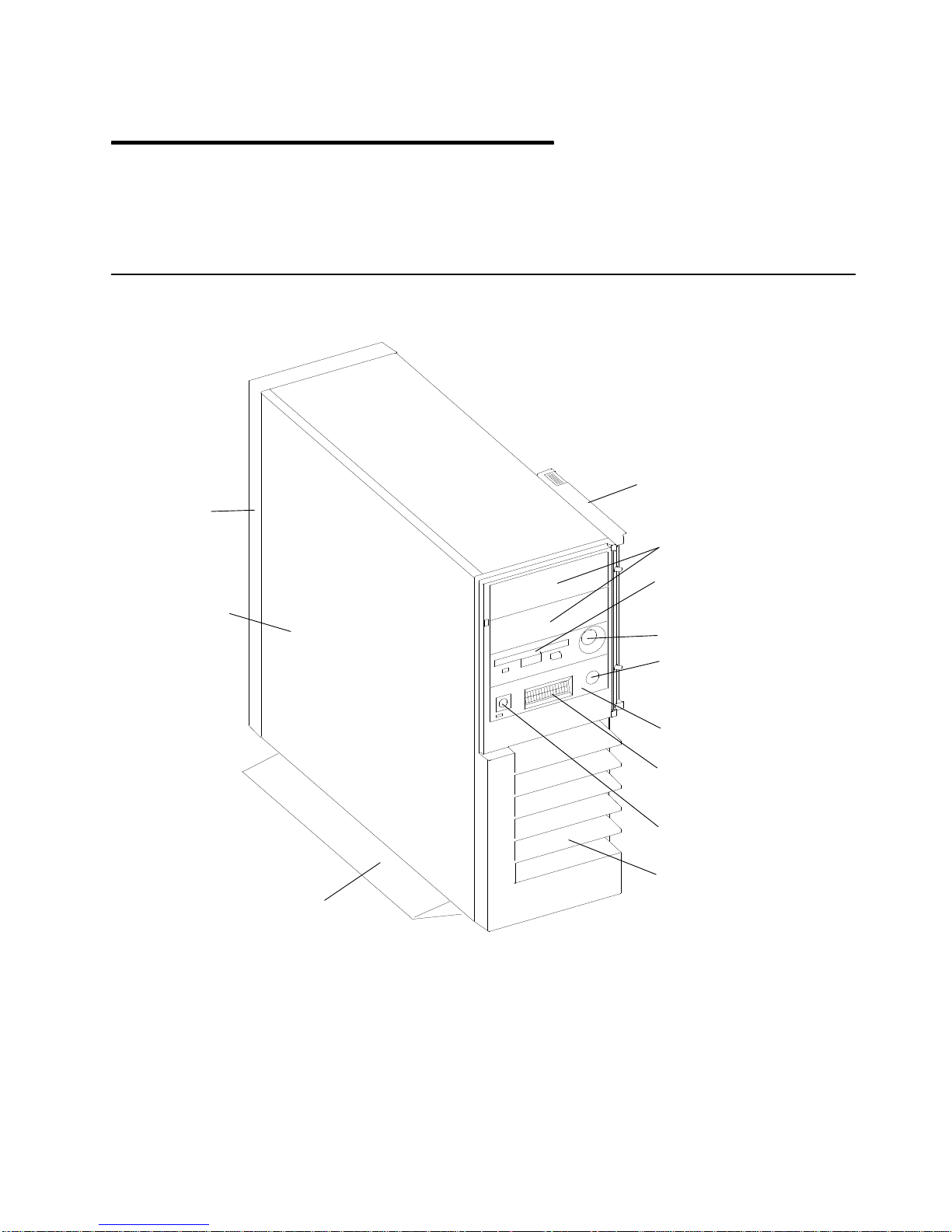
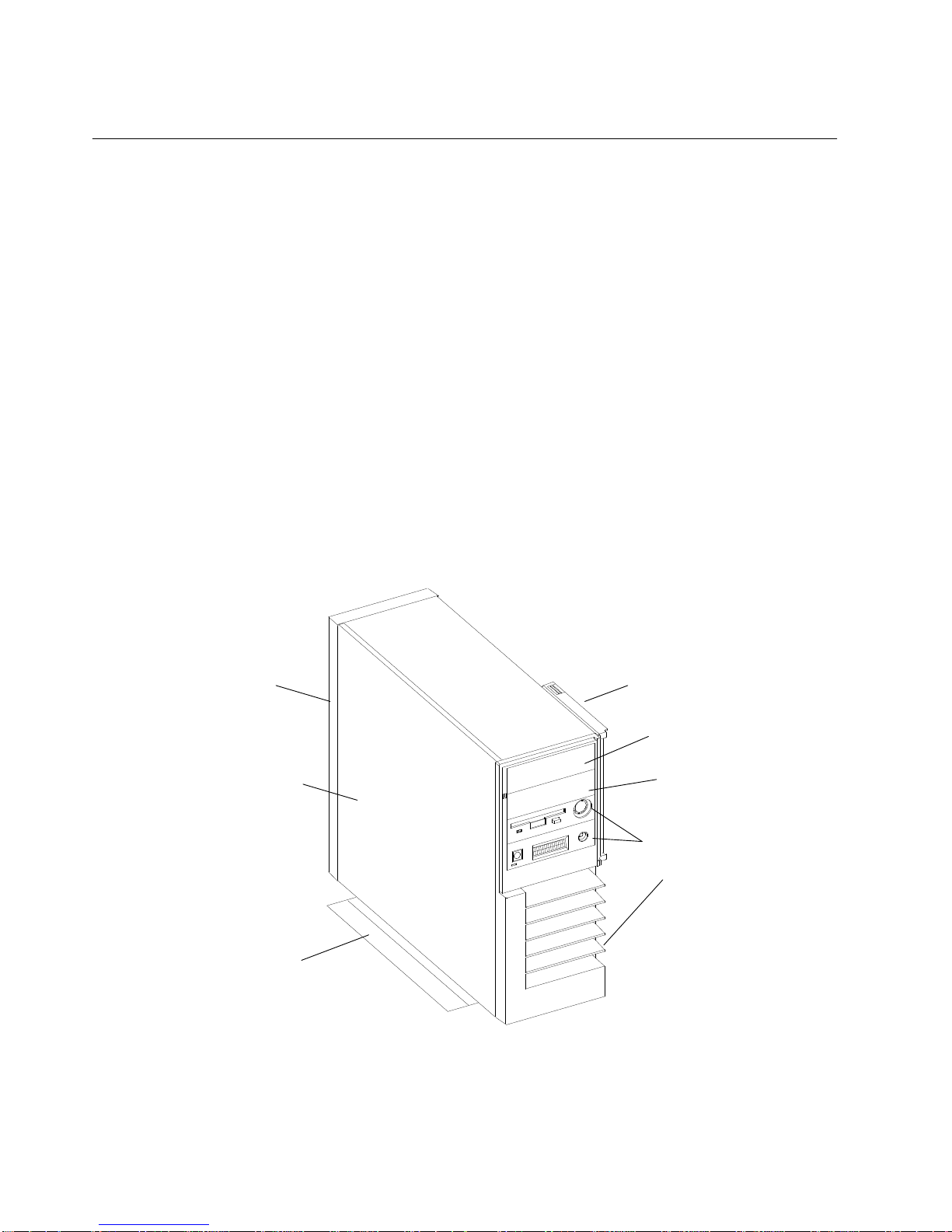
Base Unit System Unit Locations
Rear
Cover
Left Side
Cover
Front Door
Media Bays
3.5-Inch
Diskette
Drive
Key Mode Switch
Base
Reset
Button
Operator
Panel
Operator
Panel
Display
Power
Button
Front Cover
Reference Information
1-1
Page 15
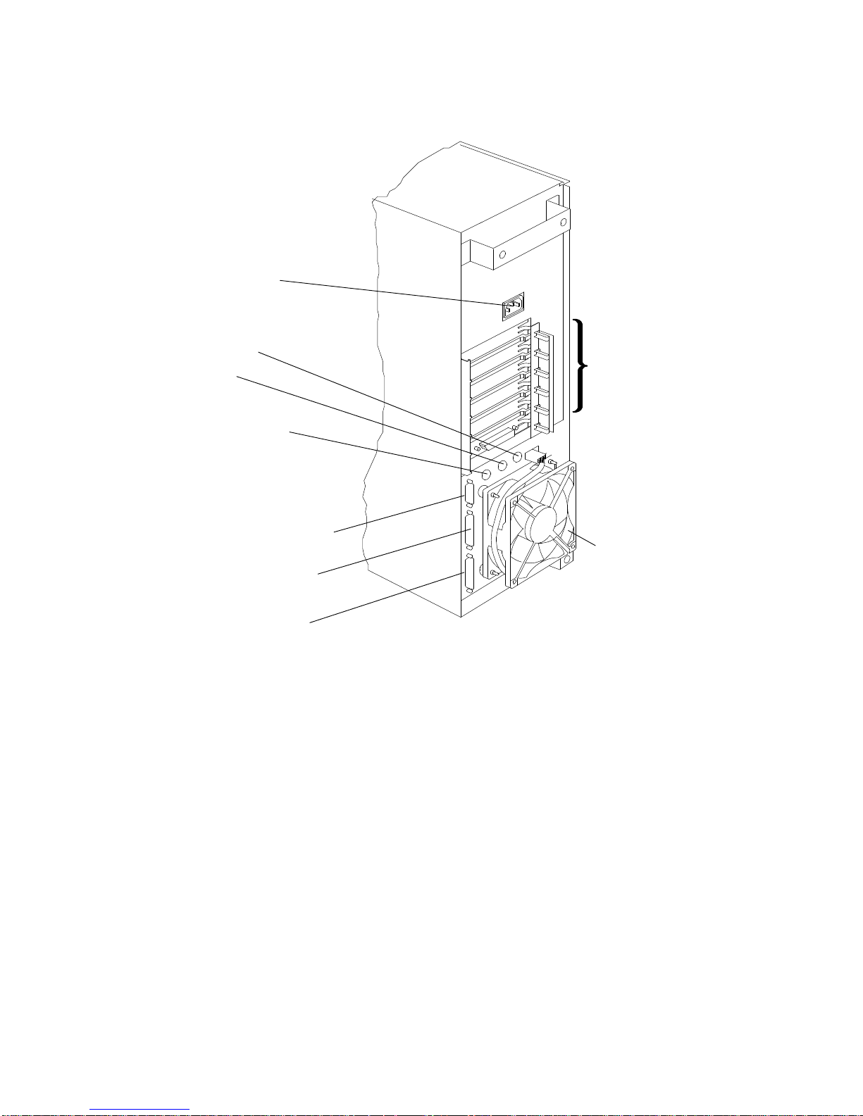
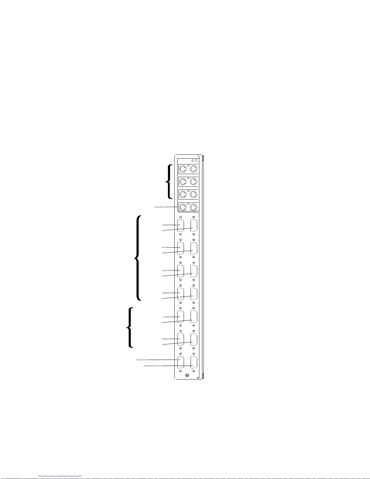
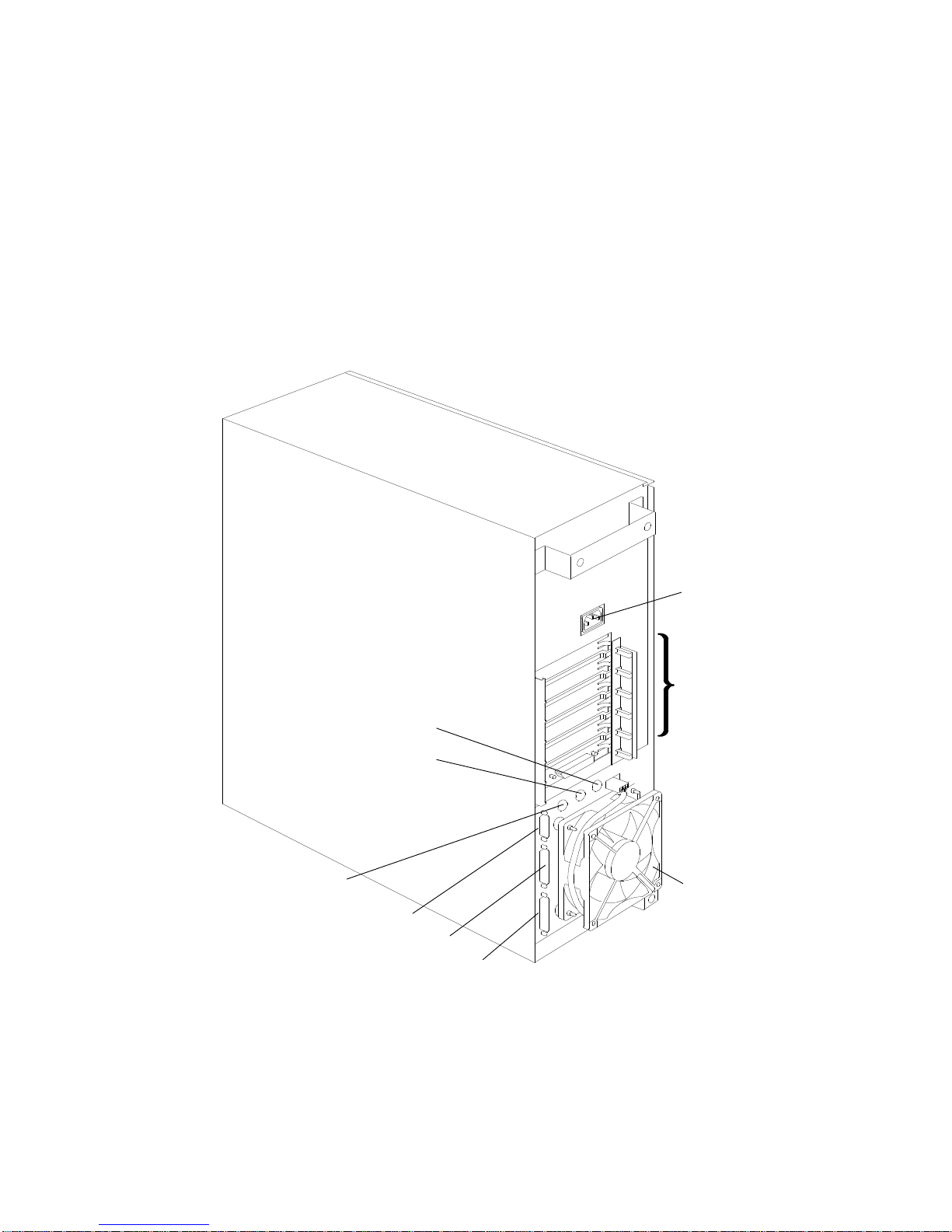
Rear View without Cover
Power Cord
Receptacle
Keyboard
Mouse
Power Control Port
(RS-485)
Adapters
9-Pin Serial Port (S3)
25-Pin Serial Port
(S1/S2)
Parallel Port (P1)
Rear
Fan
1-2 Service Guide
Page 16
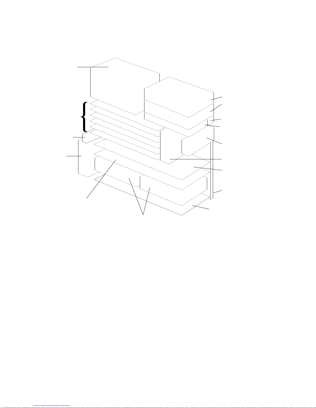
Side View without Covers
Power
Supply
Micro
Channel
Adapter
Cards
RS-485
Card
Rear
Fan
1
...........
6
Optional Second
CPU Card Position 0
or
Two Disk Drives
Positions F and G
(G30 only)
Media Drive
Position A
Media Drive
Position B
Key Mode Switch
Diskette Drive
Position C
Operator
Panel
Front Fan
First CPU Card
Position 1
System
Planar
Memory Card
Position A
Disk Drive
Positions
D and E
Reference Information
1-3
Page 17
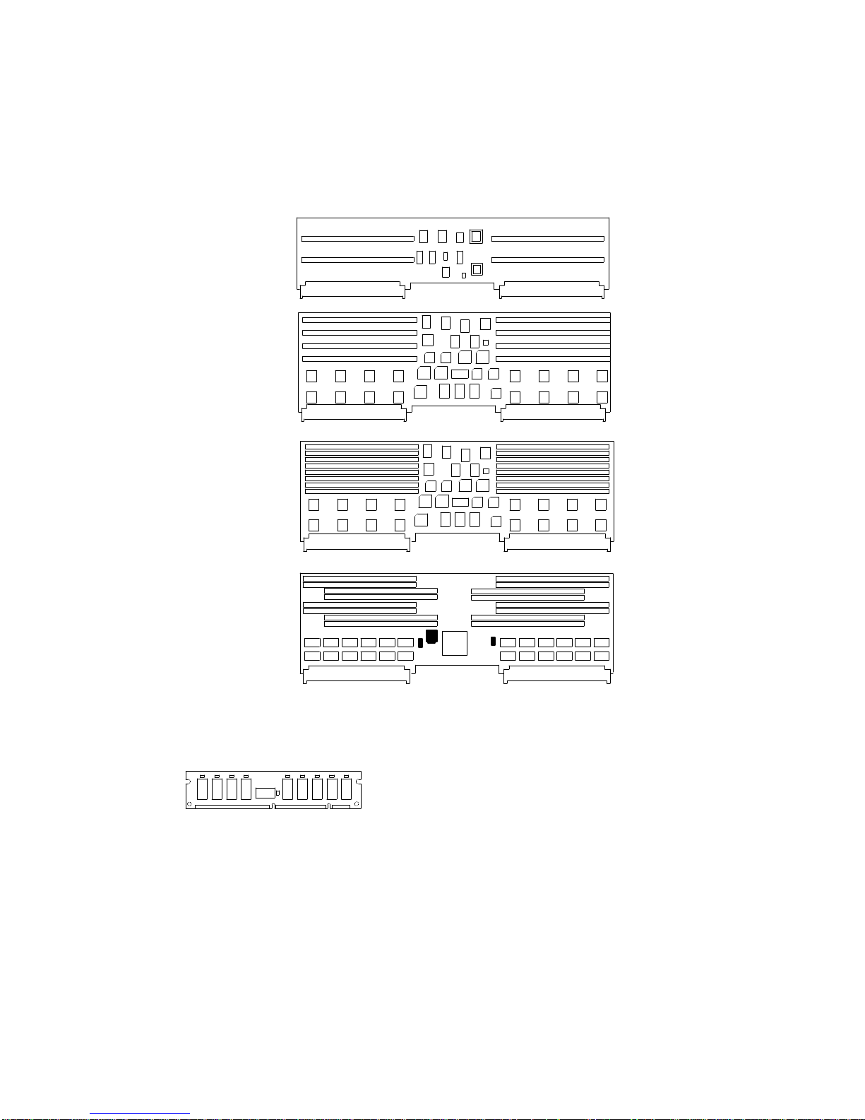
Memory Cards
There are four types of memory cards as shown below. Memory cards can house from one
to four memory module kits composed of four memory modules each, which comply with the
JEDEC standard for 68 pin, ECC, 60 ns, 5 volt memory modules. The figure below illustrates
the types of memory cards.
MRE
Memory Card
Two Bank RLX
Memory Card
Four Bank NFX
Memory Card
SF5
Memory Card
See page 4-38 for the location of the memory cards on the system planar.
The figure below shows a standard memory module.
The maximum memory reachable with this kind of memory module is 1024MB, because up
to four memory module kits can be installed on the memory card.
Modules from different size kits cannot be mixed on the same memory card.
According to both the kind and the number of memory module kits installed on the memory
cards, these can be divided into the following configurations:
• MM32, which gives 32MB memory contains four 8MB memory modules.
• MM64, which gives 64MB memory contains four 16MB memory modules.
• MM128, which gives 128MB memory contains four 32MB memory modules.
• MM256, which gives 256MB memory contains four 64MB memory modules.
1-4 Service Guide
Page 18
• NF256 board, based on 16M bit technology, which gives 256MB memory. It contains two
MM128 memory module kits.
• NF512 board, based on 16M bit technology, which gives 512MB memory. It contains four
MM128 memory module kits.
• NF1024 board, based on 16M bit technology, which gives 1024MB memory. It contains
four MM256 memory module kits.
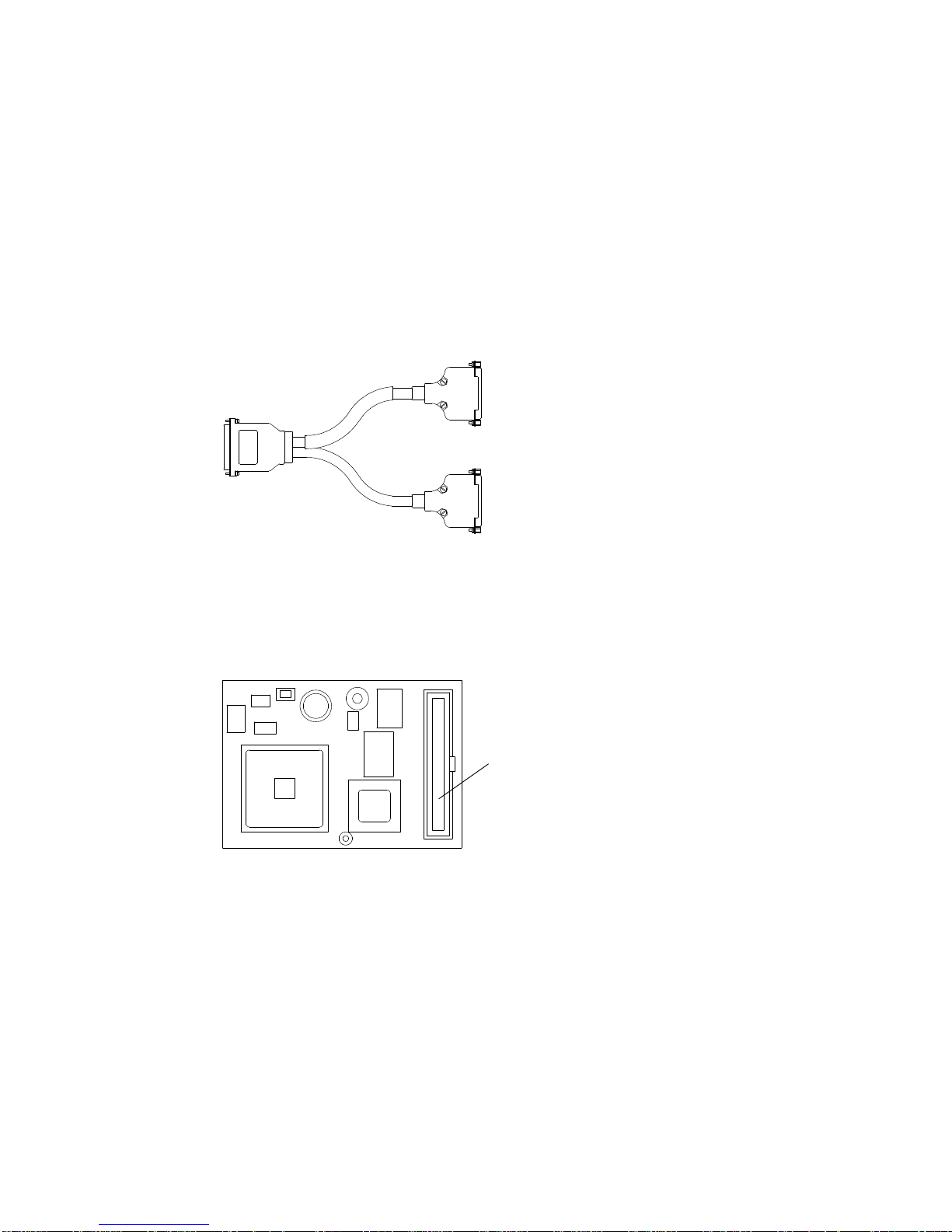
Serial Port Splitter Cable
The splitter cable is used to generate two 25-pin serial ports (S1 and S2 ports).
It is installed in the 25-pin serial port located in the rear of the base unit.
Keyboard / Mouse Card (KBD)
The KBD card is used to manage the connectors dedicated to the keyboard, mouse and
speaker capability, but not a key click option on the base unit. It must be placed on the
dedicated connector of the system planar (Y10 connector), but interfaces with the system
through the Micro Channel bus, which sees the card as occupying a Micro Channel slot.
Connector used to place
the KBD card on the system
planar
Reference Information
1-5
Page 19

Expansion Unit System Unit Locations
Description of the Disk Expansion Unit
The disk expansion unit is used to increase the number of media devices and/or disk drives.
All hardware components inside the disk expansion unit are accessible from the left side
after having removed the unit covers.
Power Supply
Media Devices
or Disk Drives
Rear Fan
Disk Drives
From the left side of the disk expansion unit, the following modules are accessible:
• Up to two 5.25-inch half height media devices (optional). Up to two 3.5-inch half height
disk drive can be installed instead.
• The operator panel (mandatory)
• The key mode switch (mandatory)
• The ECB card (mandatory)
• Up to two disk drives (optional) in the bottom tray
Key Mode Switch
Operator Panel
ECB Card
• Up to two disk drives (optional) in the upper tray
• One external cooling fan (mandatory)
• The power supply (mandatory).
1-6 Service Guide
Page 20
Rear Side
The following figure shows the rear side of the disk expansion unit.
Power Cord Connector
SCSI Connector
To Base Unit
RS-485 In Port
RS-485 Out Port
Rear Fan
Disk Expansion Unit SCSI Bus
The disk expansion unit is equipped with one internal SCSI bus. It is driven by means of a
SCSI-2 single-ended controller via an external connection.
The SCSI bus features the following characteristics:
• SCSI-2 single-ended
• 16-bit wide data bus
• Support for single-ended devices (8/16 bits)
• 8bits and 16bits SCSI devices mixable on the same bus
• Fast data transfer (10MB per second for 8bits, 20MB per second for 16bits)
• Synchronous/Asynchronous data interchange.
Reference Information
1-7
Page 21
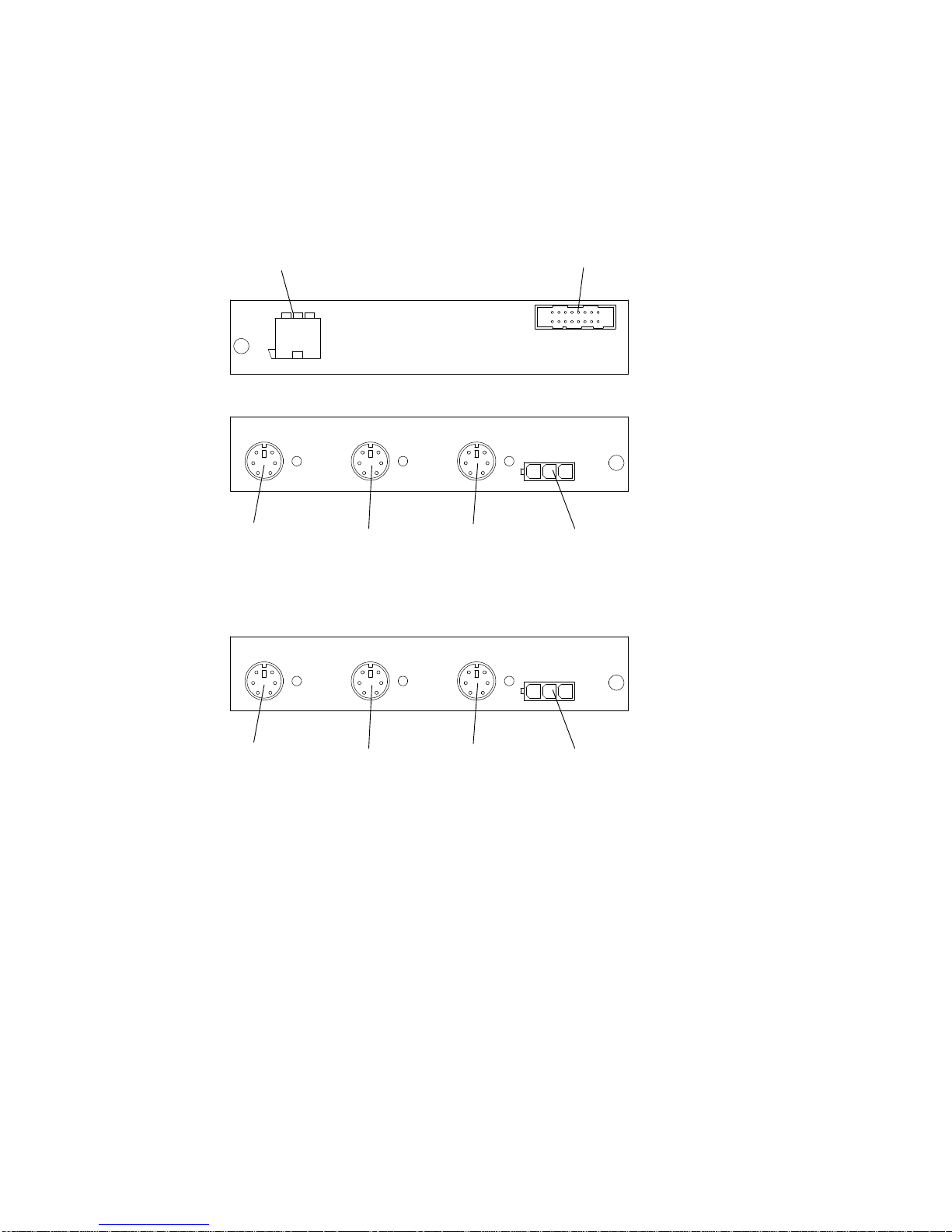
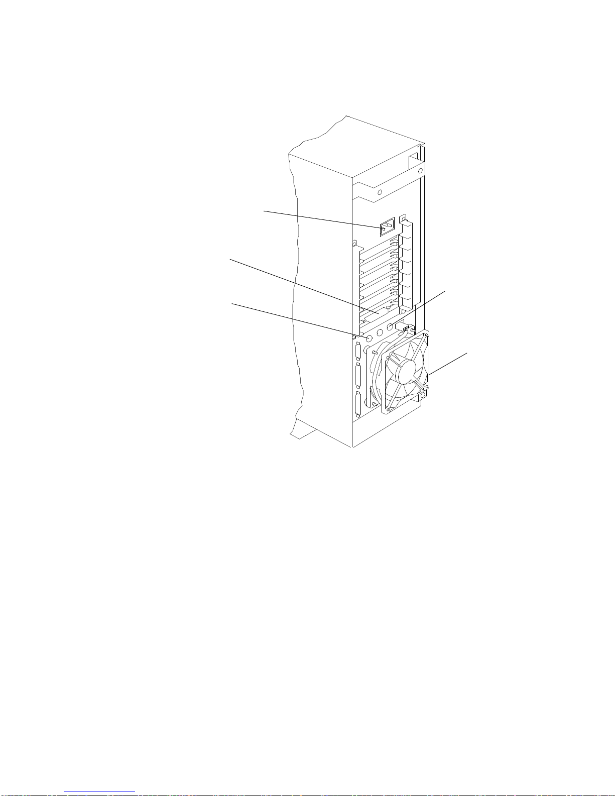
RS-485 Card
The RS-485 card is installed in the rear of both the base and the disk expansion units.
It is provided with a variety of connectors, whose functions are explained in the following
figures.
Power Connector
(Coming From the Power Supply
INTERNAL VIEW
EXTERNAL VIEW (BASE UNIT)
Mouse External FanKeyboardRS-485
EXTERNAL VIEW (DISK EXP ANSION UNIT)
Power/Signal Connector
(Coming From the Operator Panel)
1-8 Service Guide
Not Used External FanRS-485 InRS-485 Out
Page 22
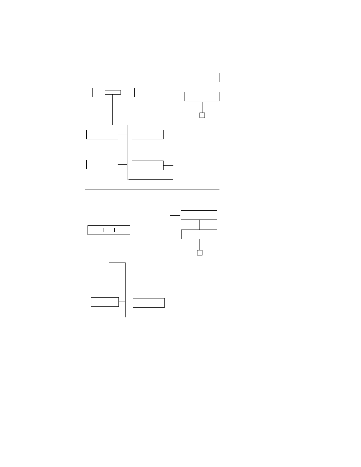
Cluster Power Control
The cluster power controller (CPC) provides:
• Connectivity between the remote support facility and multiple CPUs through the modem
• Connectivity from any attached CPU to any disk drive drawer
• Central power-on and power-off through the TTY.
The CPC provides ports for connection of multiple 7012 G Series system units, 7013 J
Series system units, and 7015 Model R30, R40, and R50 CPU enclosures for interface
connection of CPUs and disk drive drawers. The CPC also contains ports for connection of a
modem and TTY.
For more information about the CPC, refer to
Guide
, order number SA23-2766.
Disk Drive Connectors
(PCI Connectors)
Disk Drive Connectors
(RS485 Connectors)
CPU A
1
2
CPU B
1
CPU
Connectors
2
CPU C
1
2
CPU D
1
2
Cluster Power Control Operator and Service
CPC
Expansion
Connectors
TTY Connector
Modem Connector
CPC
Left
CPC
Right
1
2
1
2
Reference Information
1-9
Page 23
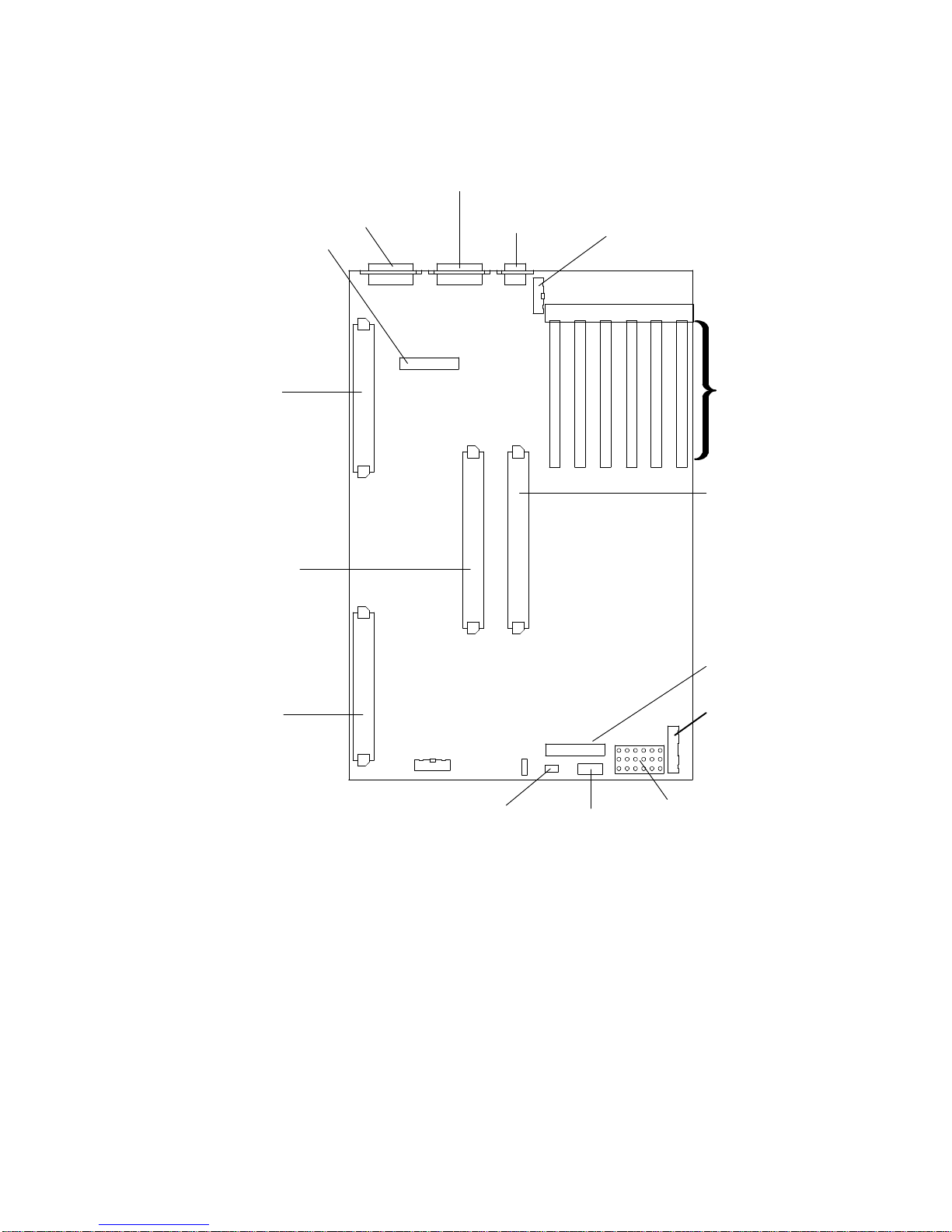
System Planar Connector Locations
Serial Ports 1 and 2
(with splitter)
Parallel
Port
Keyboard/Mouse
Card Connector
Serial Port 3
6 5 4 3 2 1
RS-485 Connector
Memory
Card
CPU Card
Position 0
Memory
Card
PQ
Battery
Connector
Operator
Panel
Connector
Micro Channel
Adapter Slots
CPU Card
Position 1
(Optional)
Diskette Drive
Connector
Power Supply
Signal Cable
Connector
Power Supply
Power Cable
Connector
1-10 Service Guide
Page 24
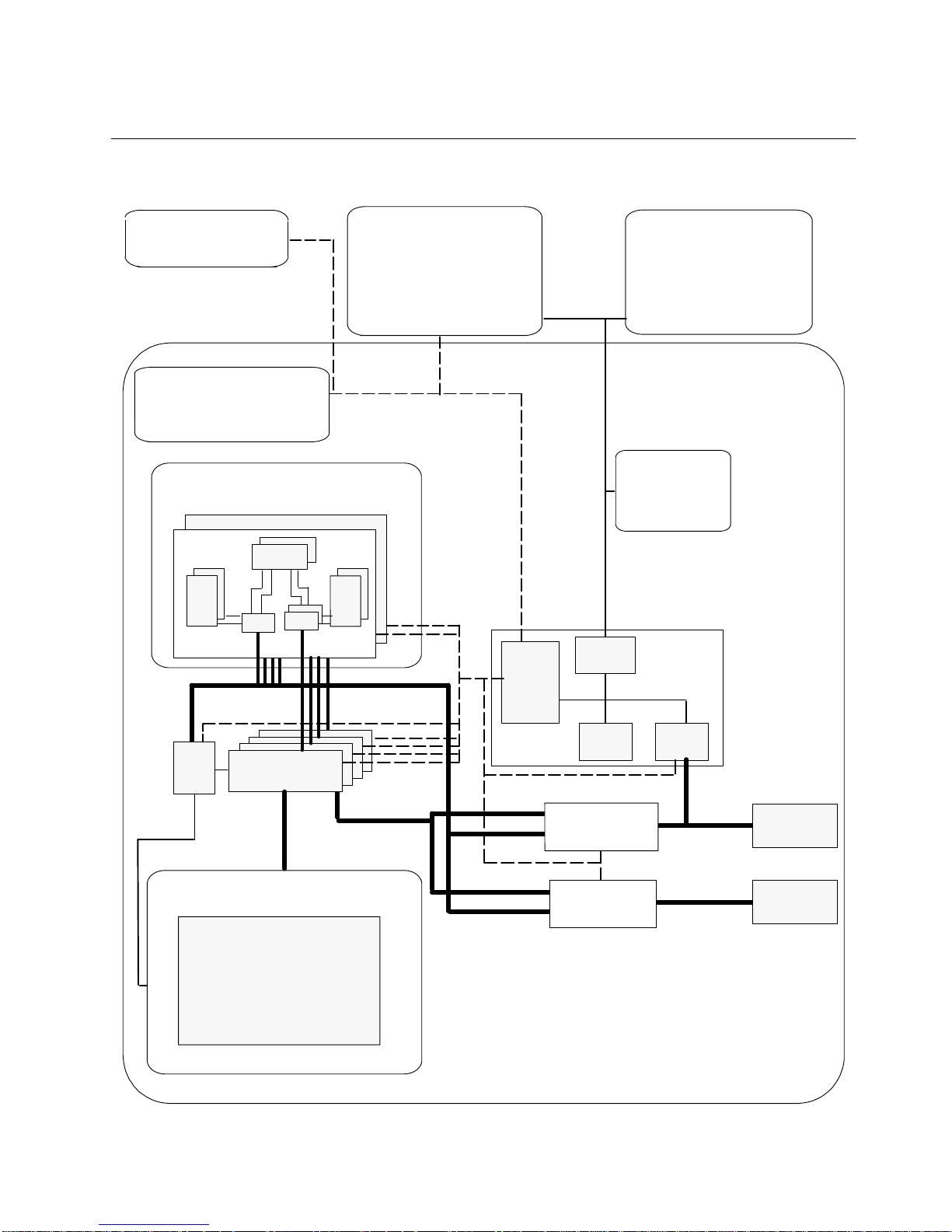
Data Flow
Power Supply
System EEPROMs
VPD EPROMs
CPU Array
CPU card
L2
Tag
SMC
CCA
60X
DCB
CCD
Operator Panel
Micro Processor
Battery
Reset/Scroll Button
LCD
Keylock
Diskette Drive
L2
CAC
Address bus
Data bus
JTAG bus
COP bus
I2C bus
BUMP
EPROM
RAM
Standard
IO
SS bus
System
IO
S1 BUMP Console
S2 Service Console
S3
Parallel Interface
System Planar
TOD Clock
NVRAM
Flash EPROM
Backup EPROM
SSGA
Memory bus
Memory Array
Memory card and DIMMs
Data bus
Base Unit I/O
Controller
Expansion Unit I/O
Controller
To
MCA bus
MCA bus
MicroChannel
Slots
To Expansion
MicroChannel
Planar
Reference Information
1-11
Page 25
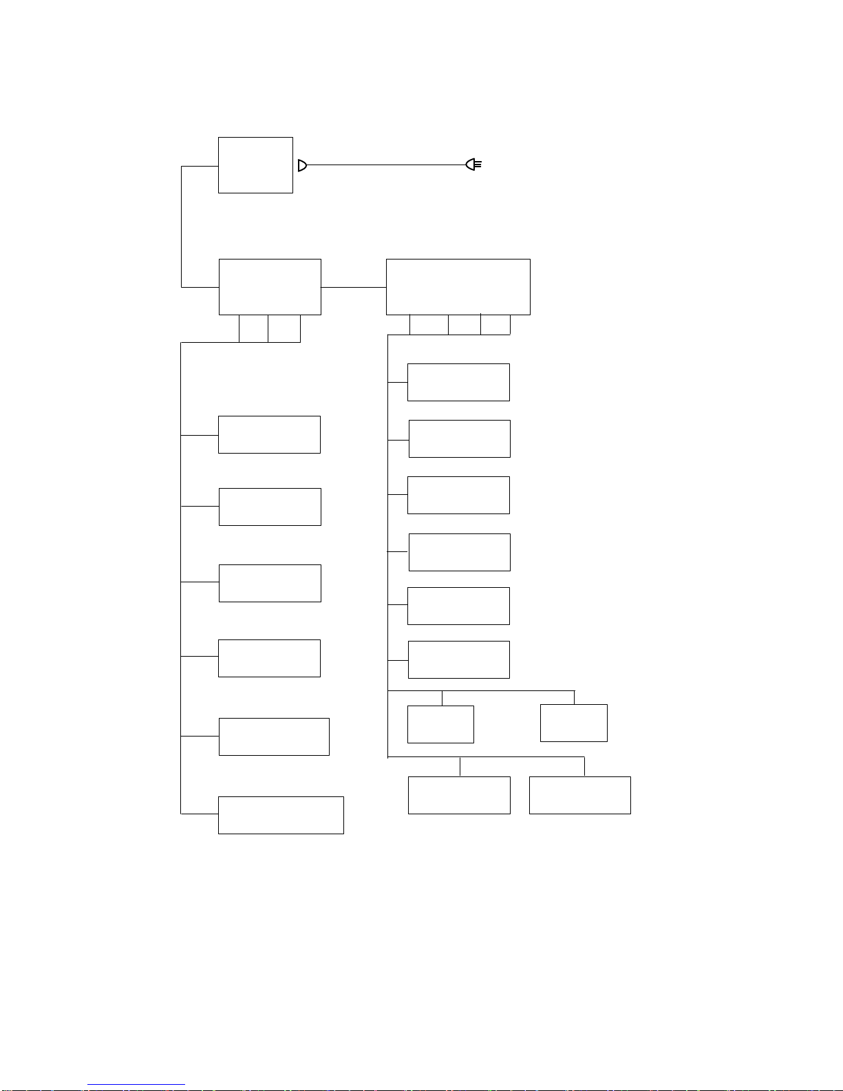
Power Flow
Power
Supply
Standby
Voltages
+5
+12 –12
EEPROM
TOD
Operator
Panel
System AC Cable
PDU
+5 +3,3/3,6 –12
Rear Fan
Module
Front Fan
Module
Memory
Card
Power
Voltages
+12
3.5-inch
Diskette
System
Planar
1-12 Service Guide
System Guard
Processor
Local Console
Access
Remote
Console Access
CPU Cards
Disk
Media
Position A
Disk
Media
Position B
Page 26
SCSI Cable Routing
SCSI controller
6-Position SCSI Cable
(4)
Upper dev.
(5)
Lower dev.
F (2)
3rd disk
D (0)
1st disk
SCSI controller
D (0)
1st disk
G (3)
4th disk
E (1)
2nd disk
4-Position SCSI Cable
E (1)
2nd disk
Terminator
(4)
Upper dev.
(5)
Lower dev.
Terminator
Reference Information
1-13
Page 27

Specifications
Dimensions (Vertical Position)
Height: 450mm (17.5 inches)
Depth: 613mm (28.2 inches)
Width: 173mm (6.9 inches)
Weight (Maximum)
19 kg to 25 kg (43 to 55 pounds)
Operating Environment – Class B
Temperature: 16
Humidity: 8% to 80%
Maximum Wet Bulb: 23
Maximum Altitude: 2133 m (7000 feet)
Power Source Loading
0.34 kVA
Power Supply
275 watts
Operating Voltage
100 V ac to 125 V ac; 50 to 60 Hz
200 V ac to 240 V ac; 50 to 60 Hz
° to 32° C (60° to 90° F)
° C (60° F)
Heat Output
1380 BTU per hour
1-14 Service Guide
Page 28

Power Cables
To avoid electrical shock, a power cable with a grounded attachment plug is provided. Use
only properly grounded outlets.
Power cables used in the U.S.A. and Canada are listed by Underwriter’s Laboratories (UL)
and certified by the Canadian Standards Association (CSA). These power cords consist of:
• Electrical cables, Type SVT or SJT.
• Attachment plugs complying with National Electrical Manufacturers Association (NEMA)
5-15P. That is:
“For 115 V operation, use a UL-listed cable set consisting of a minimum 18 AWG, Type
SVT or SJT three-conductor cord a maximum of 15 feet in length and a parallel blade,
grounding type attachment plug rated at 15 A, 125 V.”
“For 230 V operation in the U.S.A. use a UL-listed cable set consisting of a minimum 18
AWG, Type SVT or SJT three-conductor cable a maximum of 15 feet in length, and a
tandem blade, grounding type attachment plug rated at 15 A, 250 V.”
• Appliance couplers complying with International Electrotechnical Commission (IEC)
Standard 320, Sheet C13.
Power cables used in other countries consist of the following:
• Electrical cables, type HD21.
• Attachment plugs approved by the appropriate testing organization for the specific
countries where they are used.
“For units set at 230 V (outside U.S.A.): use a cable set consisting of a minimum 18
AWG cable and grounding type attachment plug rated 15 A, 250 V. The cable set should
have the appropriate safety approvals for the country in which the equipment will be
installed and should be marked ‘HAR’.”
Refer to the Parts Information section of this publication to find the power cables that are
available.
Reference Information
1-15
Page 29
Service Inspection Guide
Perform a service inspection on the system when:
• The system is inspected for a maintenance agreement.
• Service is requested and service has not recently been performed.
• An alterations and attachments review is performed.
• Changes have been made to the equipment that may affect the safe operation of the
equipment.
• External devices that have their own power cable are added.
If the inspection indicates an unacceptable safety condition, the condition must be corrected
before servicing the machine.
Note: The correction of any unsafe condition is the responsibility of the owner of the
system.
Do the following:
1. Check the covers for sharp edges and for damage or alterations that expose the internal
parts of the system unit.
2. Check the covers for proper fit to the system unit. They should be in place and secure
with the screws tight.
Rear cover
Side Cover
Base
3. Power down the system.
4. Set the power switch of the system unit to Off.
5. Unplug the power cord.
Front Door
Media Bay A
(optional)
Media Bay B
(CD-ROM
drive)
Operator Panel
Front Cover
6. Remove the covers.
1-16 Service Guide
Page 30
7. Check for alterations or attachments. If there are any, check for obvious safety hazards
such as broken wires, sharp edges, or broken insulation.
8. Check the internal cables for damage.
9. Check for dirt, water, and any other contamination within the system unit.
10.Check the voltage label on the back of the system unit to ensure that it matches the
voltage at the outlet.
11. Check the external power cable for damage.
12. With the external power cable connected to the system unit, check for 0.1 ohm or less
resistance between the ground lug on the external power cable plug and a jack screw on
the parallel port connector.
Power Cord
Receptacle
Adapters
Keyboard Port
Mouse Port
Power Control
Port (RS-485)
Rear
Fan
9-Pin Serial Port (S3)
25-Pin Serial Ports (S1/S2)
Parallel Port (P1)
13. If the system unit passes the test in the previous step, install the covers.
14. Check each external device that has its own power cable:
a. For damage to the power cord.
b. For the correct grounded power cable.
c. With the external power cable connected to the device, check for 0.1 ohm or less
resistance between the ground lug on the external power cable plug and the metal
frame of the device.
Reference Information
1-17
Page 31

Chapter 2. Using System Guard
This chapter introduces the SystemGuard service processor which is included in all
Symmetric Multiprocessor models.
Introduction
SMP servers include a service processor, called SystemGuard, as a standard feature.
SystemGuard continually monitors the hardware as well as the operating system. If, for
instance, a CPU fails, the system detects this, reboots itself automatically and runs the
built-in diagnostics on the hardware. If the CPU is detected as bad during the initial program
load (IPL) or reIPL, the CPU is disabled. Likewise, if memory is detected as bad during IPL
or reIPL, it is disabled.
SystemGuard allows diagnostics and maintenance to be performed either locally or
remotely. The SystemGuard processor makes it possible for these remote systems to be
managed from a central location. SMP servers can even be set up to automatically call a
Service Center if they fail to boot successfully.
The main features of the SystemGuard are:
• Initialization process flow management
• Local as well as remote control of the system (turning power on or off, diagnostics,
reconfiguration, maintenance)
• Console mirroring to make remote actions visible and controllable by the customer
• Dial-out to a support center in case of system boot failure
• Run-Time surveillance
Using SystemGuard
2-1
Page 32

SystemGuard Power
SystemGuard has its own DC power boundary. This means that even if the system power is
off (power button of the system in the off position), SystemGuard is still powered on, as long
as the unit is still plugged into a power outlet. This allows control of the system even though
the system is down. The only way to turn off the SystemGuard power is to unplug the AC
power cord.
SystemGuard Components
SystemGuard introduces new hardware and firmware components:
• a microprocessor called the Bring-Up MicroProcessor (BUMP)
• a Flash EEPROM
• a Backup EPROM that enables the system to boot in case of a Flash EEPROM failure.
Part of the SystemGuard firmware is stored in the BUMP EPROM; part is in the Flash
EEPROM. The Backup EPROM contains a subset of the Flash EEPROM .
SystemGuard Bring-Up MicroProcessor Overview
The SystemGuard Bring-Up MicroProcessor (BUMP) controls the system when the power is
off or the AIX operating system is stopped. SystemGuard performs the following:
• Controls the power-on (PON) tests, the power-on self tests (POST) and loading of the
AIX operating system.
• Responds to local or remote BUMP console commands to set the mode or set system
parameters.
• Runs the SystemGuard programs using the STANDBY MENU or the MAINTENANCE
MENU.
• Monitors the “heartbeat” from AIX, if the feature is enabled and AIX is running.
SystemGuard releases control of the system to the AIX operating system after it is loaded. If
the AIX operating system stops or is shutdown, SystemGuard again controls the system.
The BUMP console (attached to S1 port) provides the normal input. The service console
(attached to S2 port) provides remote service access to the BUMP. Access to both of these
consoles is controlled by flags.
2-2 Service Guide
Page 33

The Operator Panel
The Operator Panel is the first level of user interface to SystemGuard.
The Operator Panel has the following features:
Power button It should generally stay pushed in all the time if you want to be able to
Reset button It resets SystemGuard to the Init phase and, depending on the key position,
power on or off the system remotely.
reboots the system to Maintenance or to AIX Multi-User.
LCD display It is made of two rows of sixteen characters. It displays the word
in the Stand-By phase, or it displays the usual three-digit boot up codes.
Physical Key It uses the international symbols for Normal, Secure and Service modes.
This key should generally stay in the Normal position because the modes
can be changed electronically when the physical key is in the Normal
position.
Diskette Eject Button
3.5-inch
Diskette
Drive
Power-on
Button
Power-on
Light
Key Mode Switch
Stand-By
Operator Panel Display
Note: In the 7012 G Series the system board contains the NVRAM, the NVRAM battery ,
and the TOD. You can drain NVRAM by disconnecting the NVRAM battery.
When NVRAM is drained it results in a reset of the TOD to 1969 which affects
applications. Draining NVRAM also causes a loss of configuration data.
Reset Button
Using SystemGuard
2-3
Page 34

SystemGuard Consoles
SystemGuard works with two types of consoles:
• The
• The
Bump Console
console provides the normal input to the BUMP. It can be local or remote. The line speed
for the BUMP console must be set to 9600 baud for either type of connection.
Service Console,
console is usually remote and located in a customer support center or a service support
center. This console enables the support center to work with SystemGuard and/or AIX.
The support center needs specific authorization from the customer to access
SystemGuard remotely .
, which is an ASCII terminal attached to the S1 serial port. This
which is an ASCII terminal attached to the S2 serial port. This
Physical and Electronic Key
Normal, Secure, Service modes can be set physically by turning the Physical Key or
electronically by executing the electronic key command. The Physical Key and the
Electronic Key together define a state called the
be turned if the Physical Key is in Normal position. Refer to “How to Set the Electronic Key”
on page NO TAG for details on how to set the Electronic Key.
Following are various Electronic and Physical Key combinations and the resultant System
Key position:
Physical Key
normal normal normal
normal service service
normal secure secure
secure not valid secure
service not valid service
Electronic Key System Key
System Key
. The Electronic Key can only
SystemGuard Phases
During boot up, SMP servers go through five different phases: Stand-By, Init, Maintenance,
Boot, and Run-Time.
Stand-By Phase
The Stand-By phase is present anytime the system unit power is off, and the SystemGuard
power is on.
At this phase, the AIX operating system is not yet loaded; the system unit power is not on,
and the word Stand-By is displayed on the Operator Panel display.
The SystemGuard is active, and it can receive commands from the BUMP console or
Service Console (either local or remote). You can enter the SystemGuard Stand-by menu
from this phase.
The Stand-By phase ends when the power button on the Operator Panel is pressed or the
power-on command is entered on the BUMP Console or Service Console.
2-4 Service Guide
Page 35

Init Phase
Init phase is entered when the power button on the Operator Panel is pressed on or when
the power-on command is entered on the BUMP Console or Service Console.
If the System Key is in Normal mode, the BUMP runs the built-in or resident power-on
(PON)-tests on the system hardware, IPLs on the first available processor, runs the
functional power on self-tests (POST) on the I/O subsystem to check the system, and finally
loads the AIX operating system.
If the System Key is in Service mode, and if several conditions are met, the system loads
the SystemGuard MAINTENANCE MENU. These conditions are: the Autoservice IPL flag
disabled, the BUMP console enabled, and a Valid Service Contract.
If the System Key is in Secure mode, the system enters the Stall state, and the LCD
displays the three-digit code 200. The initialization of the system stops until the Physical Key
is set to Normal or Service. The Stall state is exited, and control of the system is passed to
AIX.
Maintenance Phase
The maintenance phase is entered from the Init phase if the system key is in service mode.
If the BUMP console present flag is set, the MAINTENANCE MENU is displayed on the
BUMP console, and the system waits for an operator action. The maintenance menu
choices are described on page 2-21. Various maintenance tasks can be performed from this
menu. When maintenance tasks are complete, the system can be booted, powered down, or
reset.
Boot Phase
SystemGuard enters the Boot phase from either the Init phase or the Maintenance phase. In
this phase the system is initialized and control of the system is passed to the operating
system. Control of the two serial ports is switched to the operating system and the Run-Time
phase is entered. If a valid boot block is not found and the system key is set to Service,
SystemGuard returns to the Maintenance phase.
Run-Time Phase
This is the phase where the AIX operating system is in control of the system. The Run-Time
phase is entered once the AIX operating system is loaded and takes control of the consoles.
When AIX is stopped again, for example due to a shutdown, the system goes back to the
Stand-By phase.
Using SystemGuard
2-5
Page 36

Phase Change (Stand-By to Init Stage)
The phase change from Stand-By to Init is called crossing the power boundary. This is
achieved by pushing the power button on the Operator Panel or by typing the keyword
power at the Stand-By prompt (>). Note that if you type power while the power button is not
pushed in, nothing happens until you press the power button. In this case, the power
command has been taken into account by SystemGuard, and you don’t have to reenter it.
The power command is the default power on command sequence, which you can change
from the maintenance menu or AIX service aids.
SystemGuard, checks for a special downloadable diskette (if in Service mode), checks the
Flash EEPROM, and then produces an output. The following is an example of what appears:
BUMP FIRMWARE – February 16, 1995
ID 07.01 – POWER_ON in EPROM
#
FLOPPY NOT READY!
DO YOU WANT TO UPDATE FLASH FROM LINE S2[y/n]? n
BUMP FIRMWARE – May 19, 1995
ID xx.xx – POWER_ON in FLASH PROM
The message FLOPPY NOT READY! means that there is no downloadable diskette in the
diskette drive.
Note: This message is only displayed when IPLing in Service mode.
The special diskette could be:
• Code to be downloaded into Flash EEPROM
• Code to change the VPD in the EEPROMs of the SMP system
2-6 Service Guide
Page 37

Power-on (PON) Tests
PON tests are run by SystemGuard whenever the system power comes on. There are two
types of tests:
• A comprehensive set of tests are performed on the processors, cache, memory and
related hardware when the Fast-IPL flag is disabled.
• A minimum core set of tests are performed on the processors, cache, memory and
related hardware during fast-IPL which cannot be turned off.
Following is an example of PON test output for the Fast-IPL type of test.
BUMP FIRMWARE – February 16, 1995
ID 07.01 – POWER_ON in EPROM
BUMP FIRMWARE – May 19, 1995
ID 07.04 – POWER_ON in FLASH PROM
– Low Interleaving –
Initial test on CPU 0 – * OK !
Initial test on CPU 1 – * OK !
Initial test on CPU 2 – * OK !
Initial test on CPU 3 – * OK !
Init 1024kb L2 cache by processor 0 – * OK !
Init 1024kb L2 cache by processor 1 – * OK !
Init 1024kb L2 cache by processor 2 – * OK !
Init 1024kb L2 cache by processor 3 – * OK !
Clearing 128 Mb by processor 0 –> **** OK !
CPU FIRMWARE – August 4, 1994
Processor 0 on IPL INIT
{{ 216 }}
{{ 220 }}
{{ 288 }}
{{ 278 }}
{{ 292 }}
{{ 286 }}
{{ 292 }}
Processor 0 on IPL Start
{{223}}
{{299}}
A flashing 888 is displayed if PON tests cannot start. If the PON test hangs, a three-digit
code corresponding to a failed component will be displayed.
Note that the system IPLs on the first available physical processor. If for any reason
processor 0 is not available, the system IPLs on processor 1, and then on 2 so on until a
processor is available. If all the processors are disabled, the PON test fails, and
SystemGuard treats this as a hardware component failure and goes into the
MAINTENANCE MENU in Service mode. In Normal mode, the PON test initiates dial-out, if
possible, and goes into Stall state afterward. No IPL proceeds. Processors can be manually
enabled again in Service mode through the MAINTENANCE MENU. This can also be
repaired locally by:
• Turning the system power off
• Moving the Physical Key into Service position
Using SystemGuard
2-7
Page 38

• Enabling at least one processor from the STAND-BY MENU
There are other resident PON tests to check other system resources. These tests are a
subset of the SystemGuard maintenance offline tests, and reside within the flash EEPROM.
These tests are divided into the following groups:
BUMP Quick I/O Test Group
These tests check the accessibility and the functions of the
standard and direct I/O components from the BUMP: Async lines
(S1, S2, and S3), EEPROMs, NVRAM, Flash EEPROM, and TOD
(Time-Of-Day).
JTAG (Joint Tests Action Group) Test Group
These tests check the chip-to-chip connections using the JTAG
features.
Direct I/O Test Group These tests check the accessibility of the Standard and Direct I/O
components from the CPUs: IONIAN, NVRAM access, EPROM
access, TOD, and the diskette.
CPU Test Group These tests are performed by all of the processors and check the
status of the CPU cards: processor, address translation, L1 and L2
caches.
DCB (Data CrossBar) and Memory Test Group
These tests check the status of the system planar and memory
cards: data/address lines accessibility, memory components, ECC,
memory refresh (CPU checkstop).
Interrupt Test Group These tests collectively check the interrupt system: BUMP-CPU,
CPU-CPU (CPU checkstop).
MCA Test Group Not applicable
CPU Multiprocessor Test Group
These tests check the multiprocessor mechanisms, atomic
instructions, cache coherency, main memory sharing, and
multi-resources sharing.
2
I
C Bus Test Group
The following is an example of the output when running these PON tests:
***************
* PON TESTS *
***************
.. Bump [01.01.00] DEBUG LINE TEST OK
.. Bump [01.02.00] S1 ASL (BUMP) TEST OK
.. Bump [01.03.01] S2 ASL (REM.) TEST OK
.. Bump [01.04.00] S3 ASL (SPE.) TEST OK
.. Bump [01.05.00] FLASH EP. CONTENT TEST OK
.. Bump [01.06.00] NVRAM CONTENT TEST OK
.. Bump [01.07.00] EPROM CONTENT TEST OK
.. Bump [01.08.00] TOD TEST OK
.. Bump [01.09.00] FLOPPY–D CNT. TEST OK
.. Bump [01.10.00] BPP REGISTERS TEST OK
.. Bump [01.11.00] MISC. REGS TEST OK
.. Bump [06.05.00] TOD–BUMP IT TEST OK
Note that the PON test can be suppressed if the
fast IPL
flag is enabled through
SystemGuard.
2-8 Service Guide
Page 39

Phase Change (Init to Boot)
The maintenance phase is entered from the Init phase if the system key is in service mode.
If the BUMP console present flag is set, the MAINTENANCE MENU is displayed on the
BUMP console, and the system waits for an operator action. The maintenance menu
choices are described on page 2-21. Various maintenance tasks can be performed from this
menu. When maintenance tasks are complete, the system can be booted, powered down, or
reset.
Phase Change (Maint to Boot)
SystemGuard enters the Boot phase from either the Init phase or the Maintenance phase. In
this phase the system is initialized and control of the system is passed to the operating
system.
Phase Change (Boot to AIX Load and Run-Time)
Similar to the entry into the Init phase, there is a distinct line when entering this phase. At
this line, SystemGuard gives up control of the system and passes it to the loaded code
(AIX). This is indicated by the three-digit code 299 on the consoles and Operator Panel.
Since SystemGuard is also giving up control of the two serial lines, nothing can be displayed
on the consoles. The usual three-digit boot indicators are still displayed on the Operator
Panel. Note that the code 570 virtual SCSI devices being configured can take
several minutes for each card in the SMP system.
When the boot indicators have reached c33, AIX has progressed enough to display its own
boot messages on the system console. However, this is no longer the SystemGuard
Console; it is the AIX console.
SystemGuard Parameters and Flags
A certain number of SystemGuard parameters and flags can be changed through different
SystemGuard menus, from the Diagnostics interface and from AIX. Basically, there are four
different groups of flags:
Service contract flags These flags enable Service Console usage, maintenance usage
and determine if dial-out messages are sent to IBM or to a
Customer Service Center. These flags are stored in the SID
(System Identification) field of the System EEPROM.
Diagnostics flags These flags are used to control the service, diagnostics and
maintenance from a customer point of view. For example, the
customer can modify one of these flags to authorize setting the
Electronic Key from the Service Console or to authorize the dial-out.
Modem and Site Configuration flags
These flags allow the customer to customize modem configuration
for the Service Console.
Phone numbers flags These are the dial-in and dial-out phone numbers and the operator
voice number.
Using SystemGuard
2-9
Page 40

Working with SystemGuard
You can change SystemGuard parameters and flags from different locations They can be
changed from the SystemGuard STAND-BY MENU, the SystemGuard MAINTENANCE
MENU, the Diagnostics interface, and also from AIX.
When the key signal is received, SystemGuard clears the screen and displays the
SystemGuard prompt. At this point, a keyword can be entered. The supported keywords are:
power This keyword starts the system, exactly as if the power button is pushed.
You can change, disable or enable this keyword: see “Power-On Command
Parameters” on page 2-33 for details. Turning the system power on makes
the system enter the init phase. Thus, if the Key Mode Switch is in the
Service position, and if the
Maintenance Menu
sbb This keyword displays the STAND-BY menu.
It is important to understand the following flowchart.
AutoService IPL
.
flag is disabled, you enter the
Exit
Stand-
By
Menu
Normal and Secure
Service
System
Position
Key
Normal
Auto
Service IPL
Disabled
Enter “sbb”
Yes
No
“Stand-By”
on Operator
Panel Display
Press the Enter key
(>) Console Prompt
Enter “power”
System
Key
Position
Service
BUMP
Console
Enabled
No
Stand-By
Mode
Stall State
Secure
Multi-User
AIX
2-10 Service Guide
Yes
Maintenance
Menu
Diagnostics
Page 41

When the system is in Stand-By mode and the System Key (Physical or Electronic Key) is in
Service mode, the STAND-BY MENU can be accessed and SystemGuard executed.
If you turn the system unit power on from Stand-By mode with the System Key in the Normal
position, the system boots to AIX Multi-User.
If you turn the system unit power on with the System Key in the Service position, you can go
to the MAINTENANCE MENU or to Diagnostics, depending on the state of three flags:
SystemGuard Console Present, Autoservice IPL, and Service Contract Validity.
If you power on the system with the System Key in Secure, the system stalls.
Here is some information on the meaning of the different flags:
BUMP Console Present flag
When the BUMP console is enabled, the LED codes and System Guard
messages are displayed on the console during the Init phase. If the BUMP
console is not enabled, it is like a regular system; no codes and no
messages are displayed on the console during the Init phase. Only AIX
messages appear when the system starts loading AIX.
Note that if you are running the level 5 of the SystemGuard firmware, the
BUMP Console is disabled by default, and if you enable it, it is disabled after
every shutdown. If your system is in Service mode, you might go to
Diagnostics instead of Maintenance due the SystemGuard Console being
disabled by default.
If you are running level 7 or higher of the SystemGuard firmware, the BUMP
Console is enabled by default and stays enabled after a shutdown.
Autoservice IPL flag
Service Contract flag
SystemGuard Menus
SystemGuard menus are low-level menus; they make extensive use of abbreviations or
acronyms. Refer to the glossary on page X-1 for a full list of these acronyms and
abbreviations.
SystemGuard is menu-driven, and menu choices are usually numbered. Letters are
sometimes used and can be entered in either lowercase or uppercase (SystemGuard is
case insensitive). The letter x is often used to exit the current menu and return to the
previous menu (or leave SystemGuard, if given from the main menu). Commands are only
treated after you press the Enter key. Until you press the Enter key, you can use the
Backspace key to edit a command. If you enter a command that does not match the
available options, a beep signals that an invalid selection has been made.
If enabled, this flag means that you want to go to Diagnostics when booting
with the System Key in Service mode.
This flag is preset at the factory and is not variable. The Service Contract is
always valid. This flag allows the service center to access the system and
do some maintenance. The Service Contract is set by default to an
unlimited number of days (exactly 32767 days).
Using SystemGuard
2-11
Page 42

Stand-By Menu
The STAND-BY MENU can only be entered when the system is in Stand-By mode (the word
Stand-By must be displayed on the LCD display). Perform the following steps to bring up the
ST AND-BY MENU.
1. With Stand-By displayed on the LCD display press the Enter key on the BUMP console.
2. To enter the STAND-BY MENU from here, set the System Key into Service mode, either
3. Press the Enter key again.
4. Enter the keyword sbb to display the STAND-BY MENU.
The STAND-BY MENU appears with several options, as follows:
The Stand-By prompt is the greater than (>) sign.
by setting the Physical Key to Service or the Electronic Key to Service. To set the
Electronic Key to Service, follow the procedure on page 2-39.
For Details,
See the
Following STAND–BY MENU : rev xx.xx
Pages
2-13 0 Display Configuration
2-15 1 Set Flags
2-16 2 Set Unit Number
2-17 3 Set Configuration
2-18 4 SSbus Maintenance
2-19 5 I2C Maintenance
Select(x:exit): 0
Note: It is also possible to enter the ST AND-BY MENU from the Service Console if the
remote authorization flag is enabled. The Electronic Key can be set from the Service
Console with the same escape sequence.
The STAND-BY MENU allows the system administrator to display the physical configuration
of the system (CPUs, memory, I/O, and so on) and to set flags, such as the
and the
second phase of the power-on tests. The
console to be enabled or disabled during boot up. This menu also enables the service
representative to test the interconnection between the BUMP and different components
through the I2C bus or the SSbus. For instance, it is possible to send a specific string of
characters to the LCD and read the result on the Operator Panel display. Or, it is possible to
turn on the LEDs on the Operator Panel, or to turn on the power supplies and fans without
allowing the system to IPL.
BUMP Console Present
flag. The Fast IPL flag causes the system to skip the
BUMP Console Present
flag allows the BUMP
Fast IPL
flag,
2-12 Service Guide
Page 43

How to Display the System Configuration
The system configuration can be displayed through the STAND-BY MENU or through the
MAINTENANCE MENU.
Displaying Configuration through the Stand-By Menu
This option displays the system configuration table. This configuration can be viewed on the
LCD of the Operator Panel if the console is not configured. This is done by pressing the
reset button with the mode switch in the Service position.
To display the configuration of the system, enter the STAND-BY MENU, and from the Main
menu, select Display Configuration (option 0). The first-level screen is displayed with
features and devices that can be configured.
Here is an example of the display configuration screen for a 7013 J Series system. The
screens for the 7012 G Series are similar:
Display Configuration
SID TM 7013J30 45067 SID Y2 00045067
SID Y3 7fffff003935303730370000 UNIT PAAAAAAA 40
CPU conf CCCCAAAA MM conf CCAACCAAAAAAA
FLASH_FW 0704 MM size 0080 OP_KEY NRM E_KEY SRV
OPP D78610 19H0494
SP D78605 19H0471 IOC E38030 96G4400
CPU0 D78605 19H6472 CPU1 D78605 19H6472
CPU2 CPU3
MC0 D78605 19H0473 MC1 D78605 19H0473
MC2 MC3
SIB10 E38042 19H0310 PS0 D29655 11H5114
SIB11 PS1
SIB21
SIB12 PS2
SIB22
SIB13 PS3
SIB23
Hit Return
Using SystemGuard
2-13
Page 44

Display Configuration
SIB14 PS04
SIB24
SIB15 PS05
SIB25
SIB16 PS06
SIB26 fc8e000000000000
SIB17 PS07
SIB27
MP D78605 19H0464 MPe D78605
MCA 01 C fc8e000000000000 MCAe 01 C e1ff000000000000
MCA 02 C f48e000000000000 MCAe 02 C 708f000000000000
MCA 03 C fc8e000000000000 MCAe 03 C ec8f000000000000
MCA 04 C ffde000000000000 MCAe 04 C fc8e000000000000
MCA 05 C 14e0000000000000 MCAe 05 C f0ef000000000000
MCA 06 C fc8e000000000000 MCAe 06 C 7f8f000000000000
MCA 07 C fc8e000000000000 MCAe 07 C fc8e000000000000
MCA 08 A fc8e000000000000 MCAe 08 C fc8e000000000000
Hit Return
The meanings of the configuration display fields are as follows:
• SID Y2: This is the system identification information. It is automatically updated when the
operator panel is changed.
• SID TM: This indicates the type of the model.
• SID Y3: This parameter gives the maintenance contract information in order to enable
service facilities.
• FLASH_FW: This is the Flash EEPROM firmware release number. The corresponding
second column gives the memory size expressed in KB.
• CPU Conf: This gives the status information of the CPU module (present, absent,
deconfigured, or temporarily deconfigured).
• MM Conf: This is the status information for the memory DIMM.
• UNIT ssssssss: This gives the unit status information. The corresponding second column
displays the number of RDS devices present in each unit. Each unit is denoted by two
hexadecimal digits (the first stands for RDS1 and the second for RDS2).
• SIBx EC: This indicates the system interface board (SIB) status information and the vital
product data (VPD) identifier.
• PSx EC: The power supply status and the corresponding VPD identifier information is
provided.
• SP EC+s: This parameter gives the status information and the VPD identifier of the
system planar. The technical status information is also included.
• IOC EC+s: This parameter gives the status information and the VPD identifier of the I/O
card (IOC).
• OP EC+s: This field gives the operator panel (OP) VPD values and the corresponding
status information.
2-14 Service Guide
Page 45

Set Flags
• CPUx EC+s: The agent status information of the CPU cards and the VPD information is
given.
• MCx EC+s: This field gives the memory card VPD values.
• MCAx loc. code+status: This parameter contains the location code and the status
information of the Micro Channel adapters (MCA). The contents of the 8 programmable
option select (POS) registers are also displayed in the second column.
• MPx EC: This field displays the VPD identifier of the base unit MCA planars. This field
does not appear on 7012 systems.
• MPex EC: This field displays the VPD identifier of the expansion unit MCA planars. This
field does not appear on 7012 systems and appears on 7013 systems only if the system
is attached to a 7013 J01. For 7015 systems, the second MCA planar in the CPU
enclosure is identified in this field.
• OP_KEY xxx: This field gives the value of the physical operator panel key (Key Mode
Switch). The second column shows the value of the electronic key (E_KEY).
Use this option to manage miscellaneous flags. The default values are listed in the following
table:
Flag Parameter and Keyword Default Values
Name Default Value
Remote Authorization flag Disabled
BUMP Console Present flag Enabled
Autoservice IPL flag Disabled
Extended Tests parameter Disabled
Power-On Tests in Trace Mode flag Disabled
Power-On Tests in Loop Mode flag Disabled
Fast IPL flag Disabled
Set Electronic Mode Switch to Normal NRM
1. Enter 1 in the main menu to select this option. The following screen is displayed:
Set Flags
0 Remote Authorization Disabled
1 Bump Console Present Enabled
2 Autoservice IPL Disabled
3 Extended Tests Disabled
4 PowerOn Tests in Trace Mode Disabled
5 PowerOn Tests in Loop Mode Disabled
6 Fast IPL Disabled
7 Set Electronic Mode Switch to Normal NRM
select(x:exit):
2. To set or reset a particular flag, enter its menu number.
The value set for all flags is permanent until a new change is performed (except for FAST
IPL, which is automatically cleared at boot). For a complete list of default values for flags
Using SystemGuard
2-15
Page 46

and parameters (set during manufacturing), see the table in “Default Parameter Values” on
page B–1 of the service guide for your system. The following flags can be managed:
• Remote Authorization: Only the local operator can enable this flag to enable remote
maintenance to be performed. Both the local and remote operators can disable it.
• BUMP Console Present: If enabled, SystemGuard displays the MAINTENANCE MENU
on the BUMP console (line S1). If disabled, the MAINTENANCE MENU is not available
on the BUMP console.
• Autoservice IPL: When enabled, this flag enables an automatic IPL even if the Key Mode
Switch is in the Service position, thus avoiding the display of the MAINTENANCE MENU.
• Extended Tests: This parameter determines under what conditions extended power on
self-tests are run at IPL time, after the regular power on self-tests (POSTs). If the
parameter is enabled, the extended tests are run. If the parameter is disabled, the
extended tests are not run.
• Power-On Tests in Trace Mode: When enabled, supports the running of POST tests in
trace
mode, which gives extra information about how tests are conducted. A dedicated tty
line is required, this is to be used only when directed by service support personnel.
• Power-On Tests in Loop Mode: When enabled, SystemGuard loops on the POST tests
and does not IPL.
• Fast IPL: When enabled, the long POST tests are not run, shortening the INIT phase.
This feature lets you start the machine quickly, when the test performance is not
necessary. This flag is not permanent. It only remains set until the next IPL, at which point
it is automatically cleared.
• Set Electronic Mode Switch to Normal: This command sets the Electronic Mode Switch to
the Normal position. Keep in mind that the Electronic Mode Switch is only taken into
account if the Key Mode Switch is in the Normal position. The Electronic Mode Switch is
also set to Normal each time the Key Mode Switch is moved.
Set Unit Number
Use this option to assign logical numbers to units that you add to your system.
Whenever a new unit is added, this command must be run to update the unit configuration
table.
Simply enter 2 in the main STAND-BY MENU to select this option. The process of assigning
a unit number is automatic: there is no need to pick a number.
An RS-485 bus interconnects all system and expansion units, each being addressed using a
logical number from 0, 1, 2 and so on. The base unit, where the SystemGuard and the
operator panel are present is the master of the RS-485 bus, and is always given logical
number 0. The first expansion unit is assigned the logical number 1, the second 2 and so
on.
2-16 Service Guide
Page 47

Set Configuration
This menu option enables you to configure or unconfigure units and devices.
1. Enter 3 in the main menu to select this option.
2. You should then see a first-level screen similar to the following. It displays the units and
devices that can be configured, along with their menu index number:
Set Configuration
00 CPU0 10 UNIT0 & dev
01 CPU1 11 UNIT1 & dev
02 CPU2 12 UNIT2 & dev
03 CPU3 13 UNIT3 & dev
04 MC0 14 UNIT4 & dev
05 MC1 15 UNIT5 & dev
06 MC2 16 UNIT6 & dev
07 MC3 17 UNIT7 & dev
08 base MCA
09 exp MCA .
select(x:exit):
3. Enter the menu number to select a particular object. For example, if you enter 10, then a
second-level UNIT0 screen as shown below is displayed.
The second-level screen contains a status column and details about the unit.
UNIT0 Second-level Screen
UNIT0 Set Status Set Status
00 dev0A C C 10 dev5B C A
01 dev0A D 11 dev5B D
02 dev1A C A 12 dev2A C C
03 dev1A D 13 dev2A D
04 dev3A C C 14 dev2B C D
05 dev3A D 15 dev2B D
06 dev4A C C 16 dev3B C C
07 dev4A D 17 dev3B D
08 dev5A C C 18 dev4B C D
09 dev5A D 19 dev4B D
select(x:exit):
4. Enter the object’s menu number and then enter one of the following commands:
• C: To configure the device.
• D: To unconfigure the device.
• T: To temporarily unconfigure the device. At the next power on or reset, the device is
automatically reconfigured.
For example: 06 D unconfigures device 4A.
Note: Devices that do not appear in the above list, cannot be changed.
Using SystemGuard
2-17
Page 48

SSBus Maintenance
This option is used to investigate and check devices on the SSBus and is meant only for
trained service personnel.
Use this option to investigate and check devices on the SSBus.
1. Enter 4 in the main menu to select this option. SystemGuard displays the following
menu, which allows you to read the time of day (TOD) registers and to read or write the
non-volatile random access memory (NVRAM) and lines S1 and S2.
SSBus Maintenance
2. To read data:
Command Feature start–end address
00 Read NVRAM 0x40000–0x7ffff
01 Write NVRAM
02 Read Line S1 0x000207f0
03 Read Line S2 0x000205f0
04 Read TOD 0x38000–0x3803e
05 Read date TOD
06 Read alarm TOD
select(x:exit):
a. Enter a read command number.
b. When requested, enter the start address (hexadecimal) and the length (in bytes).
c. The data at the given start address for the given length is displayed. Then the prompt
for the start address and length is shown again.
d. You can continue the read operation by pressing the Enter key, in which case a new
block of data is displayed.
e. Enter a . (dot) to end the read operation and redisplay the SSBus MAINTENANCE
MENU.
3. To write data:
a. Enter a write command number. The update is performed one byte at a time.
b. When requested, enter the start address.
c. The contents of the specified location are displayed followed by a blank. Enter a new
value followed by the Enter key.
d. The new value is written at the given address and the contents of the next location
are displayed.
e. Press the Enter key (without entering a value) to skip the current location and move to
the next location. In this case, no write is performed and the next location is shown.
f. Enter a . (dot) to end the write operation and redisplay the SSBus MAINTENANCE
MENU.
2-18 Service Guide
Page 49

2
C Maintenance
I
Use this option to do maintenance operations on the I2C buses of a selected unit, in order to
investigate and check the connected devices. When exiting this menu, the previous status of
the OP and SIB microcontrollers are restored (except for voltage margins).
1. Enter 5 in the main menu to select this option.
2. Some abbreviations used (with their meanings in parentheses) include: rd (read), wr
(write), and OP (operator panel).
2
I
C Maintenance
00 rd OP status 05 wr LCD
01 rd UNIT status 06 rd I/O port SP0
02 rd EEPROM 07 fan speed
03 margins 08 powering
04 on/off OP LEDs
select(x:exit):
These options are explained in the following sections.
Read Operator Panel Status
Enter 00 to display the OP status table.
Read Unit Status
First enter 01 to view a unit status table. Then, when requested, enter a unit number to view
its SIB table.
Read the EEPROM
Enter 02 to read the vital product data (VPD) in the EEPROM memory. Select an EEPROM
and enter its menu number to display its contents. For the SIB, PS,SYSID, and MPe
selections, enter a unit number when requested.
EEPROM list
00 SYSID/CABID 09 MC0
01 OPP 10 MC1
02 MP 11 MC2
03 SP 12 MC3
04 IOC 13 MPe
05 CPU0 14 SIB1
06 CPU1 15 PS
07 CPU2 16 SIB2
08 CPU3
select(x:exit):
Using SystemGuard
2-19
Page 50

Set voltage margins
Note: This option can be only used for error analysis or factory test and must be used only
by trained service personnel. Restore nominal voltage values before restarting other
operations. Any data written on the disk in marginal mode must be removed before
restarting normal operations. Ignore any disk errors when using this option, and
retest the disk in nominal conditions.
Set or Reset Operator Panel LEDs
Enter 04 to set or reset the operator panel display. Select an option and enter its menu
command number.
on/off LEDs Status
00 powoff Green off
01 powon Green
02 powoff Yellow off
03 powon Yellow
select(x:exit):
Write on the Operator Panel Display
Enter 05 to write a given string on the operator panel Display. When requested, enter the
string you want to display.
Read Input Output Ports
Enter 06 to read a given I/O port. The selected I/O port contents are displayed as shown
below (the example contents are hexadecimal):
fe
Hit Return
Power-on or Power-off
Enter 08 to turn a unit’s or device’s power on or off. You can also turn the power of all units
on or off using a broadcast command. Select an option and enter its menu number. These
commands are used to test the power system. When you leave the I
2
C maintenance menu,
the power of all devices will be turned off.
powering
00 broadcast ON
01 broadcast OFF
02 unit ON
03 unit OFF
04 device ON
05 device OFF
select(x:exit):
2-20 Service Guide
Page 51

Maintenance Menu
The MAINTENANCE MENU also enables you to display the configuration of the system in a
non-cryptic, easily understandable way, to perform various tests, to continue IPL either from
network, a specific SCSI device or from the boot list, and to set flags concerning various
system operation.
The MAINTENANCE MENU can only be entered by:
1. Enabling the BUMP Console from the STAND-BY MENU.
2. Setting the Autoservice IPL flag to disabled (the default value for this flag is disabled)
from the STAND-BY MENU.
3. Having a Valid Service Contract.
4. Turning the System Key to the Service position.
5. Powering-on the system.
The MAINTENANCE MENU shown below should appear just after the 292 code is
displayed on both the console and the LCD.
For Details, MAINTENANCE MENU (Rev. XX)
See the
Following
Pages
2-22 0> DISPLAY CONFIGURATION
2-25 1> DISPLAY BUMP ERROR LOG
2-25 2> ENABLE SERVICE CONSOLE
2-25 3> DISABLE SERVICE CONSOLE
2-25 4> RESET
2-25 5> POWER OFF
2-26 6> SYSTEM BOOT
2-28 7> OFF–LINE TESTS
2-32 8> SET PARAMETERS
2-38 9> SET NATIONAL LANGUAGE
SELECT:
Using SystemGuard
2-21
Page 52

Display Configuration
Use this option to view the system hardware configuration. This option provides different
screens with the following levels of information:
• System-level information
• Unit-level information
• Device-level information.
Enter 0 in the MAINTENANCE MENU to select the Display Configuration option.
Display Configuration – System Level
This screen displays general system information, such as:
• Firmware release number.
• Machine ID.
• Service Contract status.
• Total memory size, and other information.
DISPLAY CONFIGURATION
MACHINE TYPE/MODEL: 7013/J30
FIRMWARE RELEASE: Standby –> 1300
Backup eprom –> 0401
Flash eprom –> 0401
SERVICE CONTRACT: Last update (yymmdd) –> 941105
Validity–> 360 Days
Remote service support –> Valid
Quick On Call service –> Not valid
AUTO DIAL: Disable
CONSOLES: BUMP Console –> Present
Service Console –> Disable – 1200 Baud
SYSTEM ID: 000ABCDE
number of the unit)
NUMBER OF CPU: 2
MAIN MEMORY SIZE: 128 MByte
PRESENT UNITS: #0 ,#1
(Contains the serial
SELECT [Unit# (0–7) or x:exit]:
To view information for a specific unit, enter a unit number. A unit level screen is displayed,
as described on the following pages.
Note: If and expansion unit is not attached, the SELECT [Unit# (0–7) or x:exit]
option does not appear, press Enter to continue to the next screen.
Display Configuration – Unit Level
This is the second screen in the configuration group. When selected, you see two different
types of screens:
• Main Unit
• Expansion Unit.
The main unit screen, shown below, displays unit level parameters such as:
2-22 Service Guide
Page 53

• Voltage Margins for CPUs, ASICs, and other components.
• Device status information.
• Options to select various types of devices.
DISPLAY CONFIGURATION – MAIN UNIT
MARGINS VALUE: +5 VOLT –> Normal
CPU (3.65 VOLT) –> Normal
ASIC (3.6 VOLT) –> Normal
SCSI DEVICES: Present –> #0A,#3A,#4A,#5A,#2A,#2B,#3B,#4B
Deconfigured –> #2B,#4B
PRESENT CPU: #0
PRESENT MC: #0
DETAILS: 0> IOC 4> OPP
1> SP 5> PS
2> CPU 6> SIB
3> MC 7> MCA
SELECT [Details (0–7) or x:exit]:
1. To see device-level information, enter menu device type number. The device level screen
for choice 0 (I/O card) is shown on page 2-24.
Note: If you select a device type and more than one device of the same type exists, you
are asked to provide a device number. For example, if you enter 2 for CPU devices,
and 2 such device boards exist, then you have to specify CPU0 or CPU1 when
requested.
2. Enter x to return to the system-level display configuration screen.
An expansion unit screen for unit 1 is shown below. It displays:
• Unit serial number.
• Device status information.
• Options to select devices.
DISPLAY CONFIGURATION – UNIT 1
STATUS: Configured
BP SERIAL Nr.: 000ABCDE
(This field contains the serial
number of the expansion unit)
MARGINS VALUE: +5 VOLT –> Normal
SCSI DEVICES: Present –> #0A,#3A,#4A,#5A,#2A,#2B,#3B,#4B
Deconfigured –> #2B,#4B
DETAILS: 0> PS
1> SIB1
2> SIB2
SELECT [Details (0–2) or x:exit]:
Using SystemGuard
2-23
Page 54

1. To see device-level information, enter the corresponding command number for the
device. The device-level screen is displayed.
2. Enter x to return to the system-level configuration display screen.
Display Configuration – Device Level
This screen is shown when you select one of the devices of your choice from either the
Unit
or
Unit 1
screen. This option enables viewing of individual device information as shown
in the following representative screen:
• Results of diagnostic tests, such as built-in or power on self-tests (PON or POST).
• Device specific vital product data (VPD) information such as:
– Engineering change level.
– Device field-replaceable unit (FRU) number.
– Name of the manufacturer.
– Processor component definition (related to the position of the ASICs).
– Unit part number.
Note: The VPD information (restricted access) is stored in the embedded EEPROM and on
board permanent memories.
DISPLAY CONFIGURATION – MAIN UNIT (IOC)
BIST/POST: 0x0000
IOC VPD:
*EC 002 D6
*FN IOC
*MN IBM97N
*PC 0001020500020004000101000001
*PN ABCDEFGH
the system)
*RL 76971323–03276971316–031
*RM 176971331–03176706743–00104010406
*SN A0P0203400000000
*Y0 00 00ABCDE7013/J30
OF THE SYSTEM UNIT
(Will contain the part number, depending on
Main
(CONTAINS THE SERIAL NUMBER
PRESS RETURN TO EXIT:
Enter the Enter key to exit and return to the previous screen.
2-24 Service Guide
Page 55

Display BUMP Error Log
Use this option to view the BUMP firmware error log.
1. Enter 1 in the MAINTENANCE MENU to select this option. The contents of the logging
buffer are displayed as shown in the following screen:
DISPLAY BUMP ERROR LOG
EVENT # 1:
40140100000000000000000000000000000000000000000000000000000000000
00000000000000000000000000000000000000000000000000000000000000000
00000000000000000000000000000000000000000000000000000000000000000
00000000000000000000000000000000000000000000000000000000000000000
00000000000000000000000000000000000000000000000000000000000000000
00000000000000000000000000000000000000000000000000000000000000000
SELECT [+:forward event or x:exit]:
2. Use the + and – keys to scroll events on the screen forward and backward, respectively.
3. Press x to exit and return to the main menu.
Enable Service Console
Use this command to enable remote service support on the S2 line by setting the
Authorization
flag. Only the local operator can perform this command.
Remote
When this flag is enabled, remote service support is possible and all characters sent on line
S1 or line S2 are also sent on the other line.
• Enter 2 in the MAINTENANCE MENU to enable the
Disable Service Console
Use this command to prevent remote service support by disabling the
flag. This can be performed as a security measure, for example.
• Enter 3 in the MAINTENANCE MENU to disable the
Reset
This command simulates the reset action. You can use this command instead of pressing
the Reset button on the operator panel (OP).
1. Enter 4 in the MAINTENANCE MENU.
2. Confirm your action, when requested. The system is restarted from scratch, meaning that
a new initial program load (IPL) is run.
Power-Off
This command forces an immediate system power off. It is run only after the operator
confirms the action.
1. Enter 5 in the MAINTENANCE MENU.
Remote Authorization
Remote Authorization
Remote Authorization
flag.
flag.
2. Confirm your action when requested. The system powers off immediately.
Using SystemGuard
2-25
Page 56

System Boot
This command enables you to begin boot activity.
Enter 6 in the main menu to select this option. The following screen is displayed:
The menu enables you to boot in three different ways:
• Enter 0 to boot from the normal or service boot list, after completing all the maintenance
• Enter 1 to boot from a network. A network boot menu is shown.
• Enter 2 to boot from a SCSI device. A menu enables you to specify the SCSI device
• At this point, a BOOT FROM SCSI DEVICE screen appears. This displays the PRESENT
SYSTEM BOOT
0> BOOT FROM LIST
1> BOOT FROM NETWORK
2> BOOT FROM SCSI DEVICE
SELECT [x:exit]:
activity. The normal or service boot list is used, depending on the key mode.
using the location code.
DEVICE LOCATION CODE. If it is not the device you want to boot from, go through each
option, and change it to the desired BUS, SLOT, SCSI ID, and LUN ID. Option 4 allows
you to change all these options at once. The BOOT FROM SCSI DEVICE screen is
similar to the following:
BOOT FROM SCSI DEVICE
PRESENT DEVICE LOCATION CODE:
(Drawer – Bus#/Slot# – Connector – SCSI ID/LUN) 00070030
COMMANDS: 0> CHANGE BUS#
1> CHANGE SLOT#
2> CHANGE SCSI ID
3> CHANGE LUN ID
4> CHANGE DEVICE LOCATION CODE
5> BOOT FROM SELECTED DEVICE
SELECT [x:exit]:
For the following, perform either steps 1-4 and 6 (commands 0-3 and 5 ) or steps 5 and 6
(commands 4 and 5):
1. Enter 0 to select the bus identification number. The system displays:
BUS# [0>Internal | 1>External or x: exit]
BUS 0 represents the Micro Channel bus in the 7012 G Series, The Change Bus option
is not available on the 7012 G Series because the Micro Channel bus is not extended
beyond the system board.
Enter your choice. The displayed location code is updated.
2-26 Service Guide
Page 57

2. Enter 1 to select the slot number. The system displays:
SLOT# [1–6 (Internal Bus) | or x: exit]
Enter your choice. The displayed location code is updated.
Note: Bus choice is not available on 7012 systems.
3. Enter 2 to select the SCSI identification number. The system displays:
SCSI ID [0–F or x: exit]
Enter your choice. The displayed location code is updated.
4. Enter 3 to select the logical unit identification number (LUN ID). The system displays:
LUN ID [0–F (8 bit bus) | 00–1F (16 bit bus) or x: exit]
Enter your choice. The displayed location code is updated.
5. Enter 5 to begin the boot. The system leaves the maintenance environment and boots
from the specified SCSI device.
Another method of changing the SCSI Boot Device location code is to select 4 from the
BOOT FROM SCSI DEVICE menu. This method allows you to change the SLOT #, SCSI
ID, and the LUN ID simultaneously. When you make this selection, the system displays:
ENTER LOCATION CODE
(Drawer – Bus#/Slot# – Connector – SCSI ID/LUN):
Enter the new location code in the form
number,
BB
is the bus and slot number, CC is the connector, and DD is the SCSI
AA–BB–CC–DD
, where AA is the drawer
identifier and logical unit identifier.
Note: Bus choice is not available on 7012 systems.
Enter 5 to begin the boot. The system leaves the maintenance environment and boots from
the specified SCSI device.
Using SystemGuard
2-27
Page 58

Off-Line Tests
Attention: These menus are only to be used when directed by service support personnel.
Some of the tests described require test equipment or resources not available on your
system.
This option under the MAINTENANCE MENU enables you to run the off-line tests in a
controlled and interactive mode.
• Enter 7 in the MAINTENANCE MENU to select the Off Line Tests option. The following
menu is displayed.
OFF-LINE TESTS Menu
The OFF-LINE TESTS main menu, that follows, uses an empty option list by default.
OFF–LINE TESTS
OPTION LIST:
PROCESSOR LIST: Test parameter value
COMMANDS: A> VERBOSE
B> VERBOSE++
C> HALT ON ERROR
D> LOOP
E> SCOPE
F> PROCESSOR
0> BUILD TEST LIST
1> MODIFY/DISPLAY TEST LIST
2> DELETE TEST LIST
3> EXECUTE TEST LIST
4> ERROR REPORT INSPECTION
SELECT [x:exit]:
You can modify the option list field by entering the command corresponding to a particular
option. If you want to deselect a particular option (if you want to cancel the option after
selecting it) press the same command once again. In other words, the options are toggled
by the corresponding commands. The available commands are explained as follows:
A Sets the verbose option, which displays test execution messages. Without
this option, only test titles and results are displayed.
B Sets the extra verbose option, which displays the verbose messages, plus
detailed test execution messages. If this option is selected, the verbose
option is redundant and is ignored.
C Sets the halt on error option, which forces test execution to stop when the
first error is found. In this case, the error message and status are displayed.
D Sets the loop option, which continuously runs selected tests in a loop while
displaying the test identifier and loop step counter. To stop the tests, press
the Break key (Ctrl-x).
E Sets the scope option, which continuously runs the first test (in the list of
selected tests) in a loop, without displaying messages. To stop the tests,
press the Break key.
F Select the processor to run the tests.
2-28 Service Guide
Page 59

0 Displays the build test menu, which enables you to specify the test list (see
1 Displays and enables modification of the tests in the build list (see page
2 Deletes the tests in the build list, after operator confirmation. Attempting to
3 Runs selected tests (see page 2-32).
4 Displays an error report.
x Exits this menu and returns to the MAINTENANCE MENU.
Build Test List
This command is used to build a test list, which is a sequence of tests to be run. To build a
test list, perform the following steps:
1. Enter 0 from the OFF-LINE TESTS menu to display the following menu.
“Build Test List” below).
2-31).
delete tests from an empty list causes an error message to be displayed.
BUILD TEST LIST
GROUP DESCRIPTION GROUP DESCRIPTION
01 BUMP QUICK IO 03 DIRECT IO
04 CPU 05 DCB AND MEMORY
06 INTERRUPT 11 MCA
20 MULTIPROCESSOR
COMMANDS: nn> SELECT GROUP
* > ADD ALL AVAILABLE TEST TO TEST LIST
SELECT [x:exit]:
Note: For a description of the test groups, see page A-3.
2. Select a test group of your choice by entering the group ID. For example, to select the
interrupt test group, enter 06.
Note: Use the slash ( / ) character to separate different test groups. For example, enter
01/03/11 specify the BUMP Quick IO, Direct IO, and MCA test groups with default
parameter values.
Using SystemGuard
2-29
Page 60

3. Once you have selected the test groups, you can specify individual tests within a group.
For example, the following screen enables you to specify individual BUMP Quick IO
tests:
BUILD TEST LIST
GROUP 01 BUMP QUICK IO
TEST DESCRIPTION TEST DESCRIPTION
01 DEBUG LINE 02 S1 ASL (BUMP)
03 S2 ASL (REMOTE) 04 S3 ASL (SPECIFIC)
05 FLASH EPROM CONTENT 06 NOVRAM CONTENT
07 EPROM CONTENT 08 TOD
09 FLOPPY-DISK CONTROLLER 10 BPP REGISTERS
11 MISC REGISTERS 12 CPU ACCESS
13 VPD COHERENCY 50 ASL EXTERNAL L-B
51 BPP EXTERNAL L-B FULL 52 PRINTER
53 AUTODIAL 54 BPP EXTERNAL L-B
COMMANDS: nn> SELECT TEST
* > ADD ALL TEST TO TEST LIST
SELECT [x:exit]:
Attention: Do not run tests from the above list on items that do not exist on your system, a
failure indication results.
4. Select a particular test by entering the test number. The selected test is included in the
list with default parameters.
Notes:
1. Use the slash ( / ) character to separate different tests. For example, enter 01/03
to specify tests 1 and 3 with default parameter values.
2. Use the * (asterisk) character to select all available tests.
3. Attempting to add tests to a full test list causes an error message to be displayed.
2-30 Service Guide
Page 61

Modify/Display Test List
Once the test list is built, you can use this option to view or modify it. Each test is identified
by a number
1. Enter 2 in the OFF-LINE TESTS menu to view or modify the test list. The following menu
is displayed:
MODIFY/DISPLAY TEST LIST
TEST LIST (xxyy: xx = GROUP NUMBER yy = TEST NUMBER):
0101–0102–0103–0104–0105–0106–0107–0108–0109–0110–0111–0112–0150–
0151–0152
COMMANDS: xxyy> SELECT TEST
SELECT [x:exit]:
2. Select the test to be displayed or modified. For example, enter 0302 to select test 2 from
group 3.
3. When a test is selected for modification, the following screen enables you to:
– Display test parameters (both default and current values).
– Modify parameter values (reserved for service people only).
– Delete tests from the list.
xxyy
, where xx is the group number and yy is the test number.
TEST: 0101 (01/01) – GROUP 01 BUMP QUICK IO
– TEST 01 DEBUG LINE
PARAMETER[1] = Sub test selection
DEFAULT VALUE = 0x00000000 – PRESENT VALUE =
0x00000000
PARAMETER[2] = Processor number
DEFAULT VALUE = 0x00000008 – PRESENT VALUE =
0x00000008
PARAMETER[3] = Part ID
DEFAULT VALUE = 0xffffffff – PRESENT VALUE =
0xffffffff
COMMANDS: (+: forward test –: backward test)
Pn> CHANGE PARAMETER
D > DELETE TEST
SELECT [x:exit]:
4. The following commands are available:
P
n value
D Deletes the selected test.
+ Scrolls forward in the test parameter list.
[/ P
n value.
..] This command is reserved for customer service representatives.
– Scrolls backward in the test parameter list.
x Exits this menu and returns to the previous menu.
Using SystemGuard
2-31
Page 62

Execute Test List
This command enables you to run the test list once it is built (and possibly modified). All the
tests in the test list are run one at a time with the selected execution options.
• Enter 3 in the OFF-LINE TESTS main menu to run the selected tests.
The following screen displays the selected execution parameters for the test list.
EXECUTE TEST LIST
OPTION LIST:
PROCESSOR LIST: Test parameter value
>>> ENTER (CTRL_X) TO INTERRUPT TEST EXECUTION <<<
TEST 0101 Running
.. Bump [01.01.00] DEBUG LINE TEST
TEST 0103 Running
.. Bump [01.03.00] S2 ASL (REM.) TEST
PRESS RETURN TO EXIT:
• If the loop option is set, press the Break key to stop test execution. Otherwise, wait for the
tests to finish, and then press the Enter key to exit and return to the previous menu.
Set Parameters
This option under the MAINTENANCE MENU enables you to modify user-settable flags and
parameters.
1. Enter 8 in the MAINTENANCE MENU to select the Parameters Modification option.
2. The following screen is displayed:
SET PARAMETERS
0> POWER–ON COMMAND
1> VOLTAGE MARGINS
2> SET CONFIGURATION
3> PHONE NUMBERS
4> MISCELLANEOUS PARAMETERS
SELECT [x:exit] :
The following sections explain each of these options in detail.
2-32 Service Guide
Page 63

Power-On Command Parameters
During the standby idle phase, the system power can be turned on (and the IPL started) by
entering a BUMP console power-on string through line S1 or a service console power-on
string through line S2 (see “Working with
available keywords). These strings are especially useful to remotely turn on the system
power, without having to press the power button. This option allows you to enable or disable
the power-on command feature and to set the power-on strings. All specified changes only
take effect during the next initialization.
1. Enter 0 in the SET PARAMETERS menu to select this option. The following screen
displays the current settings and provides commands to change them.
POWER–ON COMMAND
PRESENT CONDITIONS: BUMP CONSOLE POWER–ON –> Enable
COMMAND STRING –> power
SERVICE CONSOLE POWER–ON –> Disable
COMMAND STRING –> power
COMMANDS: 0> ENABLE BUMP CONSOLE POWER–ON
1> DISABLE BUMP CONSOLE POWER–ON
2> CHANGE BUMP CONSOLE POWER–ON COMMAND STRING
3> ENABLE SERVICE CONSOLE POWER–ON
4> DISABLE SERVICE CONSOLE POWER–ON
5> CHANGE SERVICE CONSOLE POWER–ON COMMAND STRING
SystemGuard” on page 2-10 for a description of
2. Select an action and enter the corresponding number.
Note: The power on string is an ASCII string of 15 characters maximum.
Voltage Margins
This option enables the trained service person to set voltage margins for each unit.
Note: This option can only be used for error analysis or factory test and must be used only
SELECT [x:exit]:
by trained service personnel. Restore nominal voltage values before restarting other
operations. Any data written on the disk in marginal mode must be removed before
restarting normal operations. Ignore any disk errors when using this option, and
retest the disk in nominal conditions.
Using SystemGuard
2-33
Page 64

Set Configuration
This command is used to configure electronic boards like I/O cards or Micro Channel
adapter (MCA) devices.
1. Enter 2 in the SET PARAMETERS menu to display the SET CONFIGURATION menu as
shown below:
SET CONFIGURATION
0> CPU CARD
1> MEMORY CARD
2> BASIC MCA ADAPTER
3> EXPANSION MCA ADAPTER
SELECT [x:exit]:
2. Select the card or adapter of your choice by entering the appropriate command number.
A second-level screen lists available devices. For example, enter 2 to select Micro
Channel adapter (MCA) devices and display a screen listing available adapters, similar to
the following:
3. Select the particular device which you want to configure. A third-level screen is
4. Enter your choice in the SELECT field.
Phone Numbers
This command is used to set various service support phone numbers.
BASIC MCA ADAPTER
0> BASIC MCA ADAPTER #0
1> BASIC MCA ADAPTER #4
2> BASIC MCA ADAPTER #5
3> BASIC MCA ADAPTER #6
SELECT [x:exit]:
displayed. For example, for adapter 0 (zero), you should see a screen similar to:
BASIC MCA ADAPTER #0
PRESENT CONDITIONS: Valid & Enable
COMMANDS: 0> BASIC MCA ADAPTER ENABLE
1> BASIC MCA ADAPTER DISABLE
2> BASIC MCA ADAPTER TEMPORARY DISABLE
SELECT [x:exit]:
2-34 Service Guide
Page 65

1. Enter 3 in the SET PARAMETERS menu to display the PHONE NUMBERS menu shown
here:
PHONE NUMBERS
0> SERVICE CENTER DIAL–OUT (1) –>
1> SERVICE CENTER DIAL–OUT (2) –>
2> CUSTOMER HUB DIAL–OUT (1) –>
3> CUSTOMER HUB DIAL–OUT (2) –>
4> SYSTEM DIAL–IN –>
5> SYSTEM OPERATOR VOICE –>
SELECT [x:exit] :
2. Select the phone number you wish to modify. After you enter the number, the menu is
redisplayed with the new value. The different phone numbers are explained here:
Service Center Dial-Out Phone Number
This phone number is used by the auto dial-out procedure to
automatically report problems to a remote service center. The first
phone number, marked (1), is the primary number, and the second
is a backup number. By default, no numbers are set.
Customer Hub Dial-Out Phone Number
System Dial-In Phone Number
System Operator Voice Phone Number
Miscellaneous Parameters
This option enables you to set various flags and parameters. Flags have just two values
(enabled or disabled; or yes or no) and are toggled, while parameters can have many
different values. For a complete list of default values for flags and parameters, see the table
in “Default Parameter Values” on page B-1.
Note: There are some AIX commands which also enable you to view and modify service
information related to diagnostic flags, remote maintenance modem configurations,
and remote maintenance phone numbers. For further information, see the “Changing
Flags and Parameters Under AIX” on page B-3.
This phone number is used by the auto dial-out procedure to
automatically report problems to an internal customer service center
(customer hub). The first phone number, marked (1), is the primary
number, and the second is a backup number. By default, no
numbers are set.
This phone number is used by the dial-in procedure. This is the
phone number used by a remote service center expert to connect to
your machine by modem to perform maintenance actions. By
default, no phone number is set.
This phone number is the voice number of the customer’s system
operator or system administrator. By default, no phone number is
set.
Using SystemGuard
2-35
Page 66

• Enter 4 in the SET PARAMETERS menu to display the MISCELLANEOUS
PARAMETERS menu. The value set for all the flags, except
new change is made.
MISCELLANEOUS PARAMETERS
0> BUMP CONSOLE –> Present
1> AUTOSERVICE IPL –> Disabled
2> DIAL_OUT AUTHORIZATION –> Disabled
3> FAST IPL –> Disabled
4> SET MODE TO NORMAL WHEN BOOTING –> Enabled
5> BOOT MULTI–USER AIX IN SERVICE –> Disabled
6> SERVICE LINE SPEED –> 1200 Line speed
7> MAINTENANCE PASSWORD
8> CUSTOMER MAINTENANCE PASSWORD
9> ELECTRONIC MODE SWITCH FROM SERVICE LINE –> Disabled
SELECT [x:exit]:
BUMP Console Flag Enables the use of a console on line S1 to display the
MAINTENANCE MENU. When disabled, the MAINTENANCE
MENU is not displayed on line S1.
1. Enter 0 to toggle this flag.
2. The new flag status (opposite of the previous state) immediately
takes affect and the system continues to boot.
Fast IPL
, is permanent until a
Autoservice IPL Flag Enables the automatic bootstrap capability, allowing a boot to occur
even if the Mode Switch is in the Service position, thus avoiding the
MAINTENANCE MENU. When disabled, the MAINTENANCE
MENU is entered during the boot phase.
1. Enter 1 to toggle this flag.
2. The new flag status (opposite of the previous state) is displayed.
Dial-Out Authorization Flag
Enables automatic problem reporting to a remote service station
(with line S2) using the auto dial-out procedure. You can set the
dial-out phone numbers: see “Service Center Dial Out Phone
Number” on page 2-35. When disabled, problems are not
automatically reported to a remote service station.
1. Enter 2 to toggle this flag.
2. The new flag status (opposite of the previous state) is displayed.
Fast IPL Flag Enables the bypass of the execution of extended POST at IPL time.
This flag is not permanent, and when set, is valid for the next
initialization only. It is automatically cleared during the next AIX boot
phase.
• Enter 3 to enable this option.
Set Mode to Normal when Booting Flag
Enables the reset of the Electronic Mode Switch at boot time. When
enabled, the position is forced to Normal during each successful
boot.
2-36 Service Guide
1. Enter 4 to toggle this flag.
Page 67

2. The new flag status (opposite of the previous state) is displayed.
Boot Multiuser AIX In Service Flag
Enables multiuser AIX boots to proceed even if the Mode Switch is
in the Service position (when booting by selecting option 6 in the
MAINTENANCE MENU). When the flag is enabled, the system
boots using the bootlist defined for a Normal boot (as when the
mode switch is set to Normal). When disabled and the mode switch
is in the Service position, you cannot perform a multi-user AIX boot.
1. Enter 5 to toggle this flag.
2. The new flag status (opposite of the previous state) is displayed.
Service Line Speed Parameter
Defines the speed (baud rate) of the BUMP service line. The default
is 1200.
1. Enter 6 to set this parameter. A menu showing possible line
speeds is displayed.
2. Select a baud rate and enter the corresponding menu number.
Maintenance Password
This command sets the maintenance password, which restricts
access to basic features. If you set this password, you should give it
to service personnel when requested. By default, there is no
password.
1. Enter 7 to set the maintenance password.
2. When requested, enter the password.
Customer Maintenance Password
This command sets the customer maintenance password, which
restricts access to sensitive data such as: power on and power-off
strings; general and customer passwords; and most dial-in and
dial-out phone numbers (except for the remote service center phone
number). If you set this password, you normally should not give it to
service personnel. By default, there is no password.
1. Enter 8 to set the customer maintenance password.
2. When requested, enter the password.
Electronic Mode Switch from Service Line Flag
Enables the modification of the Electronic Mode Switch through line
S2 (the remote maintenance line). When disabled, the Electronic
Mode Switch can only be changed locally.
1. Enter 9 to toggle this flag.
2. The new flag status (opposite of the previous state) is displayed.
Using SystemGuard
2-37
Page 68

Set National Language
Use this option in the main menu to set the national language used for “SystemGuard”.
Once selected, the effect is immediate and all the console messages are presented in the
selected language.
1. Enter 9 in the MAINTENANCE MENU to select this option. The following menu is
displayed:
SET NATIONAL LANGUAGE
0> ENGLISH
1> GERMAN
2> FRENCH
3> ITALIAN
SELECT [x:exit]:
2. Select the language of your choice by entering the corresponding command number.
2-38 Service Guide
Page 69

Some Common SystemGuard Tasks
The following tasks are done through the STAND-BY and MAINTENANCE MENUs that are
part of SystemGuard. Note that these tasks can also be carried out from AIX diagnostics.
How to Set the Electronic Key
The key can be set electronically, making it easier to provide remote support without
physically touching the machine. You can do this from the Stand-By mode or from AIX.
Setting the Electronic Key from Stand-By Mode
1. Go into Stand-By mode.
2. Press the Enter key to get the prompt displayed (>).
3. Press the Enter key again. The cursor (in block mode) is then superimposed on top of
the prompt.
4. At this point, press the Escape key and then the s key. This turns the Electronic Key to
Service even though the Physical Key is still in Normal position.
5. Press the Enter key again.
6. Enter the keyword, sbb (Stand-By BUMP). You should see the STAND-BY MENU
appear; this is a way to check that the System Key is in Service.
7. Exit from the STAND-BY MENU.
At this step, if you want to go back to Normal, press the Enter key again; then press the
ESC-n key. This puts the Electronic Key to Normal position.
Setting the Electronic Key from AIX
1. While AIX is running, log in as user root.
2. Type the following command to look at the current status of the Electronic Key:
keycfg –d
3. To change the key to Service, type the following command:
keycfg –c service
4. To change the key to Secure, type the following command:
keycfg –c secure
5. To change the key back to Normal, type the following command:
keycfg –c normal
Note that, each time, you can run the keycfg –d command to verify the status of the key.
Displaying Configuration through the Maintenance Menu
The system configuration can also be displayed through the MAINTENANCE MENU. You
will find the same kind of information displayed previously, but in a different and more
readable way.
To get the system configuration from the MAINTENANCE MENU, do the following:
1. Enter the MAINTENANCE MENU.
2. Enter 0 to select DISPLAY CONFIGURATION.
The configuration display is a good picture of the SystemGuard configuration on one screen.
Here is an example:
Using SystemGuard
2-39
Page 70

DISPLAY CONFIGURATION
MACHINE TYPE/MODEL: 7013J30 45067
FIRMWARE RELEASE: Standby –> 1600
Backup eprom –> 0701
Flash eprom –> 0704
SERVICE CONTRACT: Last update (yymmdd) –> 950707
Validity –> Unlimited contract
Remote service support –> Valid
Quick On Call service –> Not valid
AUTO DIAL: Disabled
CONSOLES: BUMP Consoles –> Present
Service Console –> Disabled – 1200 Baud
SYSTEM ID: 00045067
NUMBER OF CPU: 4
MAIN MEMORY SIZE: 128 MByte
PRESENT UNITS: #0
SELECT [Unit #(0–7) or x:exit]:
This screen is self explanatory. The interesting feature here is that you can see the level of
the firmware stored in the BUMP EPROM, the level of the firmware stored in the Flash
EEPROM and the level stored in the Backup EPROM.
How to Set Fast IPL
If the Fast IPL flag is enabled, SystemGuard skips the extended POST. By default, the Fast
IPL flag is disabled; enabling it only lasts one reboot.
There are three ways to enable it: through the STAND-BY MENU in Stand-By mode, through
the MAINTENANCE MENU or by using AIX commands.
Setting Fast IPL from the Stand-By Menu
1. Set the System Key in Service.
2. Enter the STAND-BY MENU by entering sbb.
3. Enter 1 to select Set Flags.
4. Check the current status of the Fast IPL Flag. If it is disabled, enter 6 to toggle it to
enabled.
The Fast IPL flag is now enabled; the extended POST is not run when the system boots.
This saves several minutes.
The following information is contained on the SET FLAGS menu:
Set Flags
0 Remote Authorization Disabled
1 Bump Console Present Enabled
2 Autoservice IPL Disabled
3 Extended Tests Disabled
4 PowerOn Tests in Trace Mode Disabled
5 PowerOn Tests in Loop Mode Disabled
6 Fast IPL Disabled
7 Set Electronic Mode Switch to Normal NRM
select(x:exit):
2-40 Service Guide
Page 71

Setting Fast IPL through the Maintenance Menu
1. Enter the MAINTENANCE MENU.
2. Enter 8 to select the SET PARAMETERS menu.
3. Enter 4 from the SET PARAMETERS menu to select the MISCELLANEOUS
PARAMETERS Menu.
4. Option 3 in this menu should show the current status of the Fast IPL flag. If it is disabled,
simply enter 3, and the flag changes to enabled.
Fast IPL is now enabled and lasts one reboot.
Setting Fast IPL through AIX
1. Log into AIX as user
root
.
2. Type in the following command to find the
index
of the Fast IPL flag and also the current
flag value:
mpcfg –df
Following is the output of the command:
Index Name Value
1 Remote Authorization 0
2 Autoservice IPL 0
3 BUMP Console 1
4 Dial–Out Authorization 0
5 Set Mode to Normal When Booting 0
6 Electronic Mode Switch from Service Line 0
7 Boot Multi–User AIX in Service 0
8 Extended Tests 1
9 Power On Tests in Trace Mode 0
10 Power On Tests in Loop Mode 0
11 Fast IPL 0
3. The index is number 11, and, generally, the current value is zero (0), which means
disabled.
4. Type the following command to change the status of the Fast IPL flag to enabled:
mpcfg –cf 11 1
Where 11 is the index and 1 the value itself; c is for change and f for diagnostics flags.
5. Type the following command just to verify the flag is changed:
mpcfg –df
Using SystemGuard
2-41
Page 72

How to Set the Service Line Speed
By default, the service line speed is 1200 baud or 2400 baud depending
on the level of SystemGuard. This speed can be changed through the SystemGuard
MAINTENANCE MENU. In order to use the Service Console properly, the terminal
connected to the S2 connector has to be set to the same speed. This speed is not
necessarily the same as the speed defined in AIX for tty1. To avoid changing the speed of
the terminal itself when AIX is running, it is more convenient to have the same speed for the
Service Console and tty1 defined in AIX.
Setting Line Speed through the Maintenance Menu
1. Enter the MAINTENANCE MENU.
2. Enter 8 in this menu to select the SET PARAMETERS menu.
SET PARAMETERS
0> POWER–ON COMMAND
1> VOLTAGE MARGINS
2> SET CONFIGURATION
3> PHONE NUMBERS
4> MISCELLANEOUS PARAMETERS
SELECT (x:exit):
3. Enter 4 in this menu to select the MISCELLANEOUS PARAMETERS menu.
MISCELLANEOUS PARAMETERS
0> BUMP CONSOLE –> Present
1> AUTOSERVICE IPL –> Disabled
2> DIAL_OUT AUTHORIZATION –> Disabled
3> FAST IPL –> Enabled
4> SET MODE TO NORMAL WHEN BOOTING –> Disabled
5> BOOT MULTI–USER AIX IN SERVICE –> Disabled
6> SERVICE LINE SPEED –> 1200 Baud
7> MAINTENANCE PASSWORD
8> CUSTOMER MAINTENANCE PASSWORD
9> ELECTRONIC MODE SWITCH FROM SERVICE LINE –> Disabled
SELECT (x:exit):
4. Enter 6 to set this parameter. A menu showing possible line speeds is displayed.
5. Select a baud rate, and enter the corresponding menu number.
6. Exit from the menu.
2-42 Service Guide
Page 73

Setting Line Speed through AIX
1. With AIX up and running, log in as user
2. Type the following command to view current settings:
mpcfg –dm
The following is the output of the command:
Index Name Value
1 Modem Parameters File Name
2 Service Line Speed
3 Protocol Inter Data Block Delay
4 Protocol Time Out
5 Retry Number
6 Customer ID
7 Login ID
8 Password ID
3. Type the following command to change to desired baud rate:
mpcfg –cm 2 xxxx
where c stands for change, m for modem and site configuration, 2 for the Service
Line Speed index, and xxxx for your desired baud rate (9600, for example).
4. The line speed is changed, but is not effective until a reboot of the system.
How to Authorize the Service Console
The Service Console must be authorized in order to work with SystemGuard. This allows
remote support personnel to log in to SystemGuard. Service Console Authorization must
also be activated to enable mirroring. There are three ways to do it:
root
.
Authorizing Service Console through the Stand-By Menu
1. Enter the STAND-BY MENU.
2. Enter 1 from the STAND-BY MENU to select the SET FLAGS menu.
3. Check the status of the Remote Authorization flag. If it is disabled, enter 0 to toggle it to
enabled.
4. Exit from the STAND-BY MENU.
Authorizing Service Console through the Maintenance Menu
1. Enter the MAINTENANCE MENU.
2. Enter 2 to select ENABLE SERVICE CONSOLE.
3. Exit from the MAINTENANCE MENU.
Authorizing Service Console through AIX
1. With AIX running, log in as user root.
2. Type the following command to view the current setting
mpcfg –df
3. Type the following command to change the flag:
mpcfg –cf 1 1
Where –cf is for change flag; 1 is for the index. The last number, 1, is the value of the
flag itself.
Using SystemGuard
2-43
Page 74

How to Set Up Console Mirroring
Console Mirroring Concepts
Console mirroring is a way to provide the customer a view of what the person working
remotely from the Service Console is doing on the system. When mirroring is active, the
Service Console and the BUMP Console are logically identical, and both are tty0 (tty1 is
disabled when the mirroring starts).
Mirroring only works on the two serial ports, S1 and S2, and their respective ASCII consoles
or terminal emulators. It does not work on the graphical devices. The BUMP Console can be
either local (no modem connected) or remote (through a modem connection). Remote
console connection must be established through dial-in (BUMP does not dial out). The
Service Console is usually remote, connected through a Hayes-compatible modem on the
S2 port; however a local, directly attached console at the S2 port can also be supported.
T
Modem
Remote Support Center
When mirroring is active, the customer on the BUMP Console and the support personnel on
the Service Console both see the same output on their screens, and either one may enter
characters. One person can even start typing and the other finish it. For example, the
support personnel may log in as root on the Service Console, and the customer may enter
the root password on the BUMP Console. Therefore, the remote support personnel do not
need to know the root password.
T
Modem
Customer Site
S1
System Unit
S2
Console mirroring is possible during the following SystemGuard phases: Stand-By, Init and
Run-Time (AIX running).
The prerequisites for console mirroring are:
• Remote Service Support 1
• Service Contract Validity 0 – 32767
• /usr/share/modems/mir_modem file present (for mirroring when AIX is up)
2-44 Service Guide
Page 75

Setting Up Console Mirroring
In order to setup console mirroring, you need first to authorize the Service Console, and set
up the right line speed. Refer to previous chapters on how to set up the service line speed
and how to authorize the Service Console. Then do the following:
1. While AIX is running, log in as user root.
2. Type the following command to make sure that the Service Contract Validity is greater
than or equal to 0:
mpcfg –dS
The command output is:
Index Name Value
1 Remote Service Support 1
2 Quick On Call Service 0
3 Service Contract Validity 32767
4 Service Support Type
3. Wake up the mirror daemon (mirrord) by either switching the Physical Key to Service or
by typing the following command:
keycfg –c service
If mirrord is awakened successfully, you should see the following messages:
mirrord: Wait connection...
mirrord: Remote user connected, mirroring active
4. Type the following command to verify that mirrord is running:
ps –ef|grep mir
The command output is similar to the following:
root 2308 1 0 12:08:21 – 0:00 /usr/sbin/mirrord mir_modem
root 6212 4552 3 12:21:58 0 0:00 grep mir
5. Now, the support personnel should be able to work on the remote console, and the
customer should be able to watch on the BUMP Console what the service personnel
enter on the Service Console.
6. To turn mirroring off, either switch the Physical Key to Normal or type the command:
keycfg –c normal
You should see the following message:
mirrord: mirroring is stopped
If the prerequisite conditions are met, the mirrord daemon is started at boot time, but goes to
sleep until the System Key is set to Service. When mirrord is awakened, it kills all processes
on S2 and pushes the streams mirror module onto the S2 queue.
Since it is assumed that the Service Console is remote, mirrord requires a modem file that
specifies the type and characteristics of the modem. This modem file is required even if the
Service Console is connected locally without modem. Thus, a file with no modem must be
provided. The default name of the modem file is mir_modem. Please refer to the appendix
for supported modem files.
Using SystemGuard
2-45
Page 76

How to Enable Surveillance
Surveillance is implemented by the survd daemon. This daemon, when started, establishes
a heartbeat between AIX and SystemGuard. In case of an AIX hang, SystemGuard detects
it and reboots the system.
To implement the surveillance, do the following:
1. Enter:
survd –d {number of seconds}
This starts the survd daemon, thereby starting the surveillance. The number of
seconds determines the heartbeat delay time, where ten seconds is the minimum, and
the default is sixty seconds.
2. Carry out this step if you want a hardware reboot:
survd –h (–h flag sets hardware reboot)
3. To turn off the surveillance, type the following command:
survd –r
Attention: If you issue the command kill –9 <survd_proc_id>, the system reboots
because SystemGuard thinks that AIX hung since it no longer receives a heartbeat.
How to Set Up the Dial-Out Feature
The dial-out feature can be implemented, either through SystemGuard or AIX.
Setting Up Dial-Out from SystemGuard
The dial-out feature is the automatic sending of certain errors to a service center. The
customer must set the Dial-Out Authorization flag. When the Physical Key is in the Normal
position, if a boot fails due to a POST error or boot device not found, a problem report is
sent to the remote service center.
The prerequisites for the dial-out feature are:
• Remote Service Support flag enabled (1)
• Remote authorization enabled (1)
• Dial-out authorization enabled (1)
The dial-out feature uses the dial-out phone numbers listed in SystemGuard configuration.
To add or change phone numbers, do the following:
1. Enter the SystemGuard MAINTENANCE MENU.
2. Enter 8 from this menu to select the SET PARAMETERS menu.
3. Enter 3 from the SET PARAMETERS menu to select the PHONE NUMBERS menu.
4. Select your option, and enter the dial-out number or numbers. There are two service
center and customer hub numbers. These relate to primary (1) and secondary (2)
numbers.
2-46 Service Guide
Page 77

Modem Configuration
The modem on line S2 must be configured using an ASCII modem configuration file which
describes various parameters using a specific syntax. AIX uses this file directly.
SystemGuard uses the same information (in condensed form) stored in non-volatile memory
(NVRAM).
The modem line speed must be correctly set, either by using SystemGuard (see
“Miscellaneous Parameters” on page 2-35 or the diag command. The modem configuration
is used by both the dial-out and dial-in services.
The following table lists the data that SystemGuard sends to the remote support center.
Parameter
Magic Number 4 SystemGuard
Routing Metric 4 SystemGuard
Login ID 12 AIX Utility
CSS ID 4 SystemGuard
RETAIN Account Number 12 AIX Utility
General Password 16 AIX Utility
Time Stamp 8 SystemGuard
Customer System Phone 20 AIX Utility
Customer Operator Phone 20 AIX Utility
Machine Serial Number 10 SystemGuard or AIX Utility
Machine Device Type 13 SystemGuard or AIX Utility
Primary Error Code 4 SystemGuard
Destination 1 SystemGuard, HUB, or Service
SRN LCD Code 64 SystemGuard
Text Problem Abstract 64 SystemGuard
Field Size Generated By
Center
Using SystemGuard
2-47
Page 78

How to Reboot AIX from the Remote Service Console
It is possible for the remote personnel connected via the Service Console to reboot AIX from
the remote site.
Prerequisites
The following procedure must be carried out from the BUMP Console in order to allow AIX to
boot remotely from the Service Console.
1. Get into the MAINTENANCE MENU (reboot the system with the key in Service mode).
2. Enter 8 in the MAINTENANCE MENU to select the SET PARAMETERS menu.
3. Enter 0 in the SET PARAMETERS menu to select the POWER-ON COMMAND menu.
4. Enter 3 and enable Service Console Power-On.
5. Enter 5 from the same menu, and enter the string power. This string is used for
powering-on the system from the Service Console.
6. Now reboot the system in Normal mode, and log in as user
7. Type the following commands:
mpcfg –cf 1 1 to enable Remote Authorization
mpcfg –cf 2 1 to enable Autoservice IPL
mpcfg –cf 6 1 to enable Electronic Mode Switch from S2
mpcfg –cf 7 1 to enable Boot Multi-User AIX in Service
mpcfg –cf 11 1 to enable Fast IPL
8. Type the following command to start console mirroring:
keycfg –c service
Now the system is set up so that the S2 port or the remote console can activate a reboot.
The system can be rebooted either in AIX Multi-User or in Diagnostics to run diagnostics on
the hardware.
Rebooting to AIX Multi-User
1. While AIX is running, log in as user
2. Type the command:
shutdown –F –t
and press Enter, to shut down the system.
root
.
root
.
You can use the
time.
3. Once the system has shut down press Enter, you should see the Stand-By prompt (>).
4. At this prompt, type sbb to get into the STAND-BY MENU.
5. Enter a 1 at the STAND-BY MENU to select the SET FLAGS menu.
6. Enter a 7 to select Set Electronic Mode Switch to Normal
7. Once the Electronic mode switch is set to Normal, exit out of the STAND-BY MENU until
you have your prompt (>).
8. Type power at this prompt; the system should reboot.
9. You should get the AIX login prompt in about ten minutes.
2-48 Service Guide
–F
flag for a fast shutdown and/or a –t flag for a shutdown at a particular
Page 79

Rebooting to Single-User and then to Multi-User
This allows the remote support personnel connected to the system via a modem to the S2
port to shut down and reboot the system in Diagnostics mode for hardware diagnostics
purposes. After running diagnostics, the remote personnel can reboot the system in AIX
Multi-User without having a need to physically touch the machine.
1. While AIX is running, type the command:
shutdown
and press Enter, to shut down the system.
2. Once the system is shutdown press Enter, you see the Stand-By mode prompt (>).
Remember, at this point the Electronic switch is in Service mode. Leave it in Service
mode.
3. At the Stand-By prompt, type the power on keyword for S2 that we had set earlier
(power in our example).
4. The system reboots in Diagnostics. From here, diagnostic tasks can be run.
5. Once completed, activate single-user boot from the Diagnostic’s main menu.
6. You are prompted for a password; enter the root password.
7. Type the following command to reboot in AIX Multi-User:
init 2
8. After about ten minutes, the system should have rebooted and loaded AIX.
9. If S2 was configured as a tty from AIX as well, an AIX login screen appears on this
remote Service Console.
How to Boot from a SCSI Device
The SMP server can be booted in Service mode from a desired SCSI device, either from the
MAINTENANCE MENU or through the bootlist.
Booting from an SCSI Device through the Maintenance Menu
When the system is booted with the system key in Service position, it either boots in the
MAINTENANCE MENU, in Diagnostics or from a SCSI device, depending upon the various
flag settings.
Note: To be able to boot from an SCSI device other than the boot disk such as a tape
drive, the flag BOOT MULTI-USER AIX IN SERVICE must be disabled. This can be
set through the MAINTENANCE MENU. To check or change this flag, do the
following:
1. Enter the MAINTENANCE MENU; refer to the MAINTENANCE MENU section on page
2-21 for details.
2. From the MAINTENANCE MENU, enter 8 to select the SET PARAMETERS menu.
Using SystemGuard
2-49
Page 80

3. From this menu, enter 4. to select the MISCELLANEOUS PARAMETERS menu, which is
similar to the following:
MISCELLANEOUS PARAMETERS
0> BUMP CONSOLE –> Present
1> AUTOSERVICE IPL –> Disabled
2> DIAL_OUT AUTHORIZATION –> Disabled
3> FAST IPL –> Enabled
4> SET MODE TO NORMAL WHEN BOOTING –> Disabled
5> BOOT MULTI–USER AIX IN SERVICE –> Disabled
6> SERVICE LINE SPEED –> 1200 Baud
7> MAINTENANCE PASSWORD
8> CUSTOMER MAINTENANCE PASSWORD
9> ELECTRONIC MODE SWITCH FROM SERVICE LINE –> Disabled
SELECT [x:exit]:
4. Check option 5 in this menu (BOOT MULTI-USER AIX IN SERVICE). If it is enabled,
enter 5, and the flag should be changed to disabled.
5. Have another look at the option to make sure it is disabled. Now you are ready to boot off
the SCSI device, off a tape drive for example.
6. Insert the bootable tape into the tape drive.
7. Exit back to the main MAINTENANCE MENU.
8. Enter 6 in the MAINTENANCE MENU to select the SYSTEM BOOT menu, which is
similar to the following:
SYSTEM BOOT
0> BOOT FROM LIST
1> BOOT FROM NETWORK
2> BOOT FROM SCSI DEVICE
SELECT [x:exit]:
9. Enter 2 to boot from an SCSI device. The menu that appears enables you to specify the
SCSI device by using the location code.
2-50 Service Guide
Page 81

10.At this point, a BOOT FROM SCSI DEVICE screen appears. This displays the PRESENT
DEVICE LOCATION CODE. If it is not the device you want to boot from, go through each
option and change it to the desired BUS, SLOT, SCSI ID, and LUN ID. Option 4 allows
you to change all these options at once. The BOOT FROM SCSI DEVICE screen is
similar to the following:
BOOT FROM SCSI DEVICE
PRESENT DEVICE LOCATION CODE:
(Drawer – Bus#/Slot# – Connector – SCSI ID/LUN) 000600600
COMMANDS: 0> CHANGE BUS#
1> CHANGE SLOT#
2> CHANGE SCSI ID
3> CHANGE LUN ID
4> CHANGE DEVICE LOCATION CODE
5> BOOT FROM SELECTED DEVICE
SELECT [x:exit]: 5
See page 2-26 for descriptions of these fields.
11.Enter 5 to begin the boot. The system leaves the maintenance environment and boots
from the specified SCSI device.
Booting from an SCSI Device through the Bootlist
The system can be booted from an SCSI device, such as a tape drive, without going through
the MAINTENANCE MENU. In this case, it uses the bootlist to determine the boot device
while in Service mode. The bootlist can be updated through Service Aids in Diagnostics.
Following are the prerequisites for booting from an SCSI device (a tape drive for example) in
Service mode:
• The Autoservice IPL flag must be enabled.
• The Service mode bootlist must be updated (this can be done in AIX Diagnostics by
selecting Service Aids and Display/Alter Bootlist).
• A supported SCSI device, such as a tape drive.
• A bootable SCSI media, such as a bootable tape (install or mksysb).
To boot off this SCSI device, do the following:
1. Switch the System Key to Service.
2. Insert the bootable media in the SCSI device.
3. Turn on the system power.
The system then boots up from this SCSI device. If the boot up is not successful, verify that
the tape is bootable, or clean the media device.
Using SystemGuard
2-51
Page 82

How to Boot from the Network
The system can be booted from the network through the MAINTENANCE MENU. Network
boot allows a system to be reinstalled via the network and also allows various maintenance
tasks to be carried out on the local machine. Use the following procedure to boot from the
network:
1. Enter the MAINTENANCE MENU.
2. From the MAINTENANCE MENU, enter 8 to select the SYSTEM BOOT menu, which is
similar to the following:
SYSTEM BOOT
0> BOOT FROM LIST
1> BOOT FROM NETWORK
2> BOOT FROM SCSI DEVICE
SELECT [x:exit]: 1
3. From the SYSTEM BOOT menu, enter 1 to select BOOT FROM NETWORK, which is
similar to the following:
MAIN MENU
1. Select BOOT (Startup) Device
2. Select Language for these Menus
3. Send Test Transmission (PING)
4. Exit Main Menu and Start System (BOOT)
Type the number for your selection, then press ”ENTER”
(Use the ”Backspace” key to correct errors)
4. From the NETWORK BOOT MAIN MENU, enter a 1 to select the Select BOOT (Startup)
Device option.
2-52 Service Guide
Page 83

5. The SELECT BOOT (STARTUP) DEVICE menu appears, which is similar to the
following:
SELECT BOOT (STARTUP) DEVICE
Select the device to BOOT (Startup) this machine.
WARNING: If you are using Token–Ring, selection of an
incorrect data rate can result in total disruption of the
Token–Ring network.
”==>” Shows the selected BOOT (startup) device
==> 1. Use Default Boot (Startup) Device
2. Token–Ring: Slot 3, 4 Mb data rate
3. Token–Ring: Slot 3, 16 Mb data rate
4. Ethernet: Slot 4, 15–pin connector
Page 1 of 2
88. Next Page of Select BOOT (Startup) Device Menu
99. Return to Main Menu
Type the number for your selection, then press ”ENTER”
(Use the ”Backspace” key to correct errors)
6. Select the device to boot from. For example, choose 3 to boot from Token-Ring: slot 3,
16 Mb data rate. A screen similar to the following appears:
SET OR CHANGE NETWORK ADDRESSES
Select an address to change
Currently selected BOOT (startup) device is:
Token–Ring: Slot 2, 16 Mb data rate
Hardware address ................................ 10005AC97CF1
1. Client address 009.003.001.027
(address of this machine)
2. BOOTP server address 009.003.001.008
(address of the remote machine you boot from)
3. Gateway address 000.000.000.000
(Optional, required if gateway used)
97. Return to Select BOOT (Startup) Device Menu (SAVES addresses)
99. Return to Main Menu (SAVES addresses)
Type the number for your selection, then press ”ENTER”
(Use the ”Backspace” key to correct errors)
Using SystemGuard
2-53
Page 84

7. Enter the appropriate IP addresses, and enter 99 to return to the MAIN MENU. A screen
similar to the following appears:
MAIN MENU
1. Select BOOT (Startup) Device
2. Select Language for these Menus
3. Send Test Transmission (PING)
4. Exit Main Menu and Start System (BOOT)
Type the number for your selection, then press ”ENTER”
(Use the ”Backspace” key to correct errors)
8. Enter 4 to exit from the menu, and start system boot.
9. A screen similar to the following appears as the system boots off the network:
STARTING SYSTEM (BOOT)
Booting . . . Please wait.
Token–Ring: Slot 2, 16 Mb data rate
Hardware address ................................... 10005AC97CF1
Packets Sent Packets Received
BOOTP 00000 00000
To find out more information on NIM (Network Install Manager), refer to
Network Installation Management Guide and Reference
, order number, SC23-2627.
AIX Version 4.1
2-54 Service Guide
Page 85

How to Disable and Enable Processors
In the SMP servers, it is possible to disable/enable processors. A suspected faulty processor
can be disabled so that the system can run without it. The processors can be
disabled/enabled through the STAND-BY MENU, MAINTENANCE MENU, Diagnostics, or
through AIX commands.
Enabling/Disabling Processors through the Stand-By Menu
1. Enter the STAND-BY MENU; refer to the STAND-BY MENU section on page 2-12.
2. From the STAND-BY MENU, enter 3 to select the Set Configuration menu. A first-level
screen similar to the following appears:
Set Configuration
00 CPU0 10 UNIT0 & dev
01 CPU1 11 UNIT1 & dev
02 CPU2 12 UNIT2 & dev
03 CPU3 13 UNIT3 & dev
04 MC0 14 UNIT4 & dev
05 MC1 15 UNIT5 & dev
06 MC2 16 UNIT6 & dev
07 MC3 17 UNIT7 & dev
08 basic MCA
09 exp MCA
Select(x:exit): 01
The Set Configuration screen displays the units and devices that can be configured,
along with their menu index number. At this step, CPU0 stands for the CPU card 0, not
processor 0.
3. Enter an index number for a CPU card to be looked at. If you select CPU1 (01), for
example, the following screen appears:
CPU1 Set | Status
00 CPU0 C C
01 CPU0 D
02 CPU0 T
03 CPU1 C C
04 CPU1 D
05 CPU1 T
Select(x:exit): 04
4. All the CPUs and their statuses are displayed, where:
• C stands for configured
• D stands for disabled
• T stands for temporarily disabled. It means that at the next power on or reset,
the device is automatically reconfigured.
Using SystemGuard
2-55
Page 86

5. Enter 04 to deconfigure CPU1. You should see the status changed to D, disabled.
CPU1 Set | Status
00 CPU0 C C
01 CPU0 D
02 CPU0 T
03 CPU1 C D
04 CPU1 D
05 CPU1 T
Select(x:exit):
6. Now, once the system is rebooted, it runs without processor 1.
7. To enable CPU1, follow the same procedure as above, except choose a status C (03 in
this example).
8. Exit the STAND-BY MENU, and continue booting the machine.
Enabling/Disabling Processors through the Maintenance Menu
1. Enter the MAINTENANCE MENU. Refer to the MAINTENANCE MENU section on page
2-21 for details.
2. Enter 8 to select the SET PARAMETERS menu, which is similar to the following:
SET PARAMETERS
0> POWER–ON COMMAND
1> VOLTAGE MARGINS
2> SET CONFIGURATION
3> PHONE NUMBERS
4> MISCELLANEOUS PARAMETERS
SELECT [x:exit]: 2
3. Enter 2 from the SET PARAMETERS menu to select the SET CONFIGURA TION menu,
which is similar to the following:
SET CONFIGURATION
0> CPU CARD
1> MEMORY CARD
2> BASIC MCA ADAPTERS
SELECT [x:exit]: 0
CPU CARD [0> CPU0| 1> CPU1 or x:exit]: 1
4. Enter 0 from this menu to select the CPU CARD option.
2-56 Service Guide
Page 87

5. The CPU CARD screen appears and looks similar to the following:
CPU CARD – (CPU1)
PRESENT CONDITIONS: PR #0 –> Valid & Enabled
PR #1 –> Valid & Enabled
COMMANDS: 0> ENABLE
1> DISABLE
2> TEMPORARY DISABLE
SELECT [x:exit]:
6. From this screen, you can disable or enable a particular processor on the selected CPU
card. Option 0 enables a CPU; option 1 disables a CPU, and option 2 temporarily
disables a CPU until the next reboot.
Enabling/Disabling Processors through AIX
The processors can be disabled/enabled through AIX as well. This is done through the
cpu_state command. Following is the command with various options:
• To list the processors and view their statuses, type cpu_state –l. The output should
look something like this:
Name Cpu Status Location
proc0 0 enabled 00–0P–00–00
proc1 1 enabled 00–0P–00–01
proc2 2 enabled 00–0Q–00–00
proc3 3 enabled 00–0Q–00–01
• To disable a CPU, CPU1 for example, type cpu_state –d 1. Look at the result with
cpu_state –l:
Name Cpu Status Location
proc0 0 enabled 00–0P–00–00
proc1 1 disabled 00–0P–00–01
proc2 2 enabled 00–0Q–00–00
proc3 3 enabled 00–0Q–00–01
Note: This change does not take effect until after a reboot. After a reboot, the cpu_state
–l command shows:
Name Cpu Status Location
proc0 0 enabled 00–0P–00–00
proc1 – disabled 00–0P–00–01
proc2 1 enabled 00–0Q–00–00
proc3 2 enabled 00–0Q–00–01
Using SystemGuard
2-57
Page 88

Customizing SystemGuard For Your Needs
SystemGuard is controlled by several flags. The flags consist of Contract Flags, Operational
Flags, Remote Maintenance Flags, and Test Flags.
Remote Service Flag
This flag is disabled at the factory and must be enabled for remote service
Operational Flags
The Operational Flags are the
to Normal When Booting
customized for your needs.
BUMP Console
flag, which are enabled at the factory, however, they can be
flag, the
AutoService IPL
flag, and
Set Mode
BUMP Console
The
enabled, the console attached to Serial Port 1 is shared with the operating system. It is
recommended that this flag always be enabled if a console is attached to Serial Port 1. This
flag can be set from the Set Flags menu, MISCELLANEOUS PARAMETERS menu, or the
Service Aids.
The
AutoService IPL
when the system is booted in Service Mode. This enables the system to be booted quicker
when installing the operating system and when loading the diagnostics. It is recommended
that this flag always be enabled unless there is a need to use the MAINTENANCE MENU.
This flag can be set from the Set Flags menu, MISCELLANEOUS PARAMETERS menu, or
the Service Aids.
The
Set Mode to Normal When Booting
Key to Normal when booting. It is recommended that this flag always be enabled. This flag
can be set from the MISCELLANEOUS PARAMETERS menu or the Service Aids.
Test Flags
The Test Flags are the
PowerOn Tests in Loop Mode
disabled at the factory. They are used during testing and do not need to be customized.
Remote Maintenance Flags
The Remote Maintenance Flags are the
flag, and
however, they can be customized for your needs.
Electronic Mode Switch from Service Line
flag enables the SystemGuard Console attached to Serial Port 1. If
flag instructs SystemGuard to bypass the MAINTENANCE MENU
flag instructs SystemGuard to reset the Electronic
Boot Multiuser AIX in Service
flag, and
PowerOn Tests in Trace Mode
Remote Authorization
flag,
Fast IPL
flag. They are disabled at the factory,
flag,
Extended Tests
flag. They are
flag,
Dial-Out Authorization
flag,
The
Remote Authorization
Remote Console and to report problems to a remote site. If enabled, Serial Port 2 is shared
with the operating system. The setting of this flag depends if you are using remote
maintenance or not. This flag can be set from the Set Flags menu, MISCELLANEOUS
PARAMETERS menu, or the Service Aids.
The
Dial-Out Authorization
prevent the system from booting to be reported to a remote site via Serial Port 2. The setting
of this flag depends if you are using remote maintenance or not and if you want problems
that prevent the system from booting to be reported to a remote site. This flag can be set
from the Set Flags menu, MISCELLANEOUS PARAMETERS menu, or the Service Aids. If
this flag is enabled, a Service Center Dial-Out phone number must be set.
The
Electronic Mode Switch from Service Line
be controlled from the Service Console. The setting of this flag depends if you want the
Electronic Mode Switch to be controlled from the Service Line or not. This flag can be set
from the MISCELLANEOUS PARAMETERS menu or the Service Aids.
2-58 Service Guide
flag enables the SystemGuard Console to use Serial Port 2 for a
flag enables the SystemGuard Console to report problems that
flag enables the Electronic Mode Switch to
Page 89

Phone Numbers
If remote maintenance is used, SystemGuard requires several phone numbers to be
entered. Additional information is provided in “Phone Numbers” on page 2-34.
Service Line Speed Parameters
If remote maintenance is used, SystemGuard requires that the line speed be configured.
The default is 1200 baud. The speed can be set by MISCELLANEOUS PARAMETERS
menu or the Service Aids.
Modem Parameters
If remote maintenance is used, SystemGuard may require that the Modem Parameters file
be updated. This file can be set by the Service Aids.
Passwords
Passwords are used to protect access to SystemGuard. The passwords are the
Maintenance Password and the Customer Maintenance Password. No passwords are set at
the factory. However, they can be customized for your needs. The Maintenance Password
restricts access to basic features of the MAINTENANCE MENU. If you set the password you
should provide it to your service personnel when requested. The Customer Maintenance
Password restricts access to sensitive customer data. If you set the password you normally
should not provide it to your service personnel. The passwords can be set from the
MISCELLANEOUS P ARAMETERS menu.
Using SystemGuard
2-59
Page 90

Reloading the Flash EEPROM
Follow this procedure to load a new version of SystemGuard into the flash EEPROM. Only
system administrators should perform this procedure.
Prerequisites
To install a new version of the FLASH EEPROM firmware, you need either a firmware
diskette containing a binary firmware image, or a file containing the firmware.
You can also update the firmware using a file containing a new firmware version.
Updating the Flash EEPROM (using a firmware diskette)
If the system is not yet powered on, simply insert the firmware diskette in the drive, place the
Mode Switch in the Service position, and then power on the system. The firmware diskette is
identified by a special header which distinguishes it from diskettes containing other data.
The existing firmware recognizes the special header and automatically loads the new
firmware version.
If AIX is already up and running (the run-time phase), reloading the firmware requires more
steps, because you first have to shut down the system, then reboot the machine as
described in the preceding paragraph.
Updating the Flash EEPROM (using a file)
An administrator with root authority can use the AIX diag command to update the EEPROM
firmware using a file. Because this procedure reboots the machine after the update, the root
user who performs this procedure should be the only logged user. If the system is not yet
powered on, power on the system, and log in as the root user without letting other users log
in. Then follow the steps to use when the system is up and running.
If AIX is already up and running (the run-time phase), perform the following steps:
1. Make sure that no other users are logged in to the system (log them out if necessary).
2. Make sure that you have root authority (use the su command if necessary).
3. Enter the diag command or load diagnostics when the Key Mode switch is in the
Service position.
4. Select Service Aids.
5. Select the
6. Select the
7. Enter the full path name for the file containing the new flash EEPROM image. The image
file installed with the operating system is located in the /usr/lpp/devices.base directory.
8. The system is automatically rebooted.
BUMP Service Aids
Flash Eprom Download
option.
option.
2-60 Service Guide
Page 91

Chapter 3. Maintenance Analysis Procedures (MAPs)
MAP 1520: 7012 G Series System Unit - Power Map
Note: This is not a start of call MAP. Use this Power MAP only if you have been directed
here from a MAP step in the
Systems
This procedure is used to locate power problems in 7012 G Series system units. If a
problem is detected, this procedure helps you isolate the problem to a failing unit.
Note: If you need more detailed information about the Power/Keylock Status Register
(PKSR) bit definitions when using this map, see Error Logging, on page D-26. A
detailed description of the system power states can be found in “Appendix E.
System Power States.”
Observe the following safety notice during service procedures.
.
Diagnostic Information For Micro Channel Bus
Note: For a translation of these notices, see
DANGER
An electrical outlet that is not correctly wired could place hazardous voltage
on metal parts of the system or the products that attach to the system. It is
the responsibility of the customer to ensure that the outlet is correctly wired
and grounded to prevent an electrical shock.
Before installing or removing signal cables, ensure that the power cables for the
system unit and all attached devices are unplugged.
When adding or removing any additional external devices to or from the system,
ensure that the power cables for those devices are unplugged before the signal
cables are connected. If possible, disconnect all power cables from the existing
system before you add a device.
Use one hand, when possible, to connect or disconnect signal cables to prevent
a possible shock from touching two surfaces with different electrical potentials.
During an electrical storm, do not connect cables for display stations, printers,
telephones, or station protectors for communication lines.
CAUTION:
This product is equipped with a 3-wire power cable and plug for the user’s safety.
Use this power cable in conjunction with a properly grounded electrical outlet to
avoid electrical shock.
System Unit Safety Information
.
Maintenance Analysis Procedures (MAPs)
3-1520-1
Page 92

Power Supply Status
In 7012 G Series models, if the system detects a power supply failure on the base unit or
MCA expansion unit, it turns the power off and displays SRN 409-Axy, where xy is the
hexadecimal value of the power status register and gives some information on the power
fault, as described in this MAP.
If the power fault condition occurs on the disk expansion unit, while the system is running,
the system may detect the fault and log the error; however, if a reboot is launched, the
system will recognize the power fault and display 409-Axy SRN.
Line two of the operator panel display identifies the unit that contains the error. Units are
numbered as:
0 Base System unit
1 Expansion unit
Step 1
You may be directed to this MAP for several reasons:
1. SRN 409-Axy appears on the operator panel display: a power fault has been detected
on some unit and the entire system has been powered off.
Go to Step 9.
2. The power button has been pressed (set to on), but the power does not stay on; no
information remains displayed on the operator panel display.
Step 2
(from Step 1)
Go to step 2.
1. Set the power button on the system unit to Off.
2. Unplug the system from the electrical outlet.
3. Set the key mode switch to the Service position.
4. Plug the system into the electrical outlet.
Is anything (even a blinking cursor) displayed in the operator panel display?
NO Go to Step 3
YES Go to Step 7
3-1520-2
Service Guide
Page 93

Step 3
(from Step 2)
Step 4
(from Step 3)
Is the operator panel display illuminated?
NO Go to Step 4
YES Go to Step 6
1. Check that the external power cable to the system unit has continuity.
2. Check that the external power cable is plugged into both the system unit and the power
outlet. To check the power cable on the system side you must unmount the unit rear
panel. See “Rear Cover”, on page 4-8.
3. Check that the power outlet has been wired correctly with the correct voltage.
Did you find a problem?
NO Go to Step 5.
Step 5
(from Step 4)
YES Correct the problem. Go to “Map 0410: Repair Checkout” in the
Information For Micro Channel Bus Systems
Note: Either the Power Supply (99 % failure probability) or the system planar (1 % failure
probability) is defective.
1. Unplug the system unit power cable from the wall outlet.
2. Replace the Power Supply. See “Power Supply” on page 4-44.
3. Connect the system unit power cable to the wall outlet.
Has the symptom changed?
NO Reinstall the original Power Supply.
Repeat Step 5 exchanging the system planar. See “Base Unit System
Planar” on page 4-46.
If you exchanged both Power Supply and system planar with no results, call
your service support person for assistance.
YES Go to “Map 0410: Repair Checkout” in the
Channel Bus Systems
.
Diagnostic Information For Micro
Diagnostic
Maintenance Analysis Procedures (MAPs)
3-1520-3
Page 94

Step 6
(from Step 3)
Note: Either the Operator Panel (99 % failure probability) or the system planar (1 % failure
probability) is defective.
1. Unplug the system unit power cable from the wall outlet.
2. Exchange the operator panel. See “Operator Panel” on page 4-11.
3. Connect the system unit power cable to the wall outlet.
4. Be sure that the key mode switch is set to the Service position.
Has the symptom changed?
NO Reinstall the original Operator Panel.
Repeat Step 6 exchanging the system planar. See “Base Unit System
Planar” on page 4-46.
If you exchanged both operator panel and system planar with no results,
call your service support person for assistance.
Step 7
(from Step 2)
YES Go to “Map 0410: Repair Checkout” in the
Channel Bus Systems
Note: Stand-By should appear on the Operator Panel Display.
Is Stand-By displayed on the Operator Panel Display?
NO If an SRN is displayed, go to “Map 0210: General Problem Resolution” in
the
Diagnostic Information For Micro Channel Bus Systems
blinking cursor is displayed, record SRN 409-083 and go to “Map 0210:
General Problem Resolution” in the
Channel Bus Systems
YES Go to Step 8.
.
.
Diagnostic Information For Micro
. If only a
Diagnostic Information For Micro
3-1520-4
Service Guide
Page 95

Step 8
(from Step 7)
1. Power on the system unit, with the key mode switch set to Service.
2. Find your symptom in the following table; then follow the instructions given in the Action
column.
Symptom
The power-on light does not come on or
comes on and does not stay on.
An SRN is displayed on the Operator
Panel.
Note: Some systems do not power on if
the mode switch is in the Secure position.
Ensure that the mode switch is in the
Service position. If it is not, place the
mode switch in the Service position, and
start over at the beginning of this substep.
The power-on light comes and stays on. Note: It is not a Power Supply fault.
Action
If SRN is 409–Axy, go to step 9, otherwise
find the SRN in the Service Request
Number List in the
For Micro Channel Bus Systems
the listed action.
If there is an SRN displayed on the
Operator Panel, Find the SRN in the
Service Request Number List in the
Diagnostic Information
; then do
Diagnostic Information For Micro Channel
The power on light does not come on or
comes on and does not stay on.
Stand-By is displayed on in the Operator
Panel Display .
Bus Systems
If there is no SRN, Go to MAP 1540.
The problem may be caused by a
defective system planar or operator panel.
Use “MAP 0410” in
For Micro Channel Bus Systems
out the repair.
; then do the listed actions.
Diagnostic Information
to check
Any other symptom. Call your service support person for
assistance.
Maintenance Analysis Procedures (MAPs)
3-1520-5
Page 96

Step 9
(from Step 1 and 8)
The xy value in SRN 409-Axy is the hex value for the Power Status Register byte. Line 2 of
the operator panel display identifies the unit that contains the error. The bits in the Power
Status Register are defined as follows:
8 4 2 1 8 4 2 1 = Hex value of bits
7 6 5 4 3 2 1 0 = Bit numbering
Over / under voltage on +5 volts
Overload (over current) on +5 volts
Overload (over current) on +12, +3.3, or +3.6 volts
Over / under voltage on +12, +3.3, or +3.6 volts
Ignore
Ignore
First level over temperature detected by the power
supply
Second level over temperature detected by the
power supply
For example, 56 (0101 0110) represents bits 6, 4, 2, and 1. A zero indicates the active
state.
Is bit 6 or bit 7 a zero?
NO Go to Step 11.
YES Go to Step 10.
3-1520-6
Service Guide
Page 97

Step 10
(from Step 9)
An over temperature problem can be caused by an environmental problem (see
Specifications on page 1-15 in
each of these items.
Did you find the problem?
NO Go to Step 11.
7012 G Series Service Guide
) or blocked air ducts. Check
YES Repair the problem. Go to “Map 0410: Repair Checkout” in the
Step 11
(from Steps 9, 10)
Is bit 1 or bit 2 a zero?
NO Replace the power supply.
YES Go to “MAP 1540: 7012 G Series System Unit - Minimum Configuration” on
Diagnostic
Information For Micro Channel Bus Systems
If the symptom did not change, reinstall the original power supply. Call your
service support person for assistance.
Go to “Map 0410: Repair Checkout” in the
Channel Bus Systems
page 3-1540-1.
.
.
Diagnostic Information For Micro
Maintenance Analysis Procedures (MAPs)
3-1520-7
Page 98

3-1520-8
Service Guide
Page 99

MAP 1540:7012 G Series Minimum Configuration
Note: This is not a start of call MAP. You should use this MAP only if you have been
directed here from a MAP step in the
Systems
Purpose of this MAP
This MAP is used to locate defective FRUs not found by normal diagnostics. For this
procedure, diagnostics are run on a minimum-configured system. If a failure is detected on
the minimum-configured system, the remaining FRUs are exchanged one at a time until the
failing one is identified. If a failure is not detected, FRUs are added back until the failure
occurs. The failure is then isolated to the failing FRU.
The MAP steps on the following pages instruct you to reduce the system to one or more of
the following configurations:
Minimum Configurations for the 7012 G Series Systems:
– System planar, operator panel, CPU card, and memory card.
If no failure is detected, the maintenance menu is displayed. Any other response
means one of the remaining FRUs is failing.
– System planar, operator panel, CPU card, memory card, and a BUMP console
attached to the S1 port.
– System planar, operator panel, CPU card, memory card, CD-ROM drive, SCSI adapter
and a BUMP console attached to the S1 port.
.
Diagnostic Information For Micro Channel Bus
If no failure is detected, the Diagnostic Operating Instructions frame is displayed when
the diagnostics are loaded, and the system console is selected. Any other response
means that one of the remaining parts is failing.
Maintenance Analysis Procedures (MAPs)
3-1540-1
Page 100

Step 1
(from Step 3, 6, 7, 9, 10, 17)
1. Ensure that the diagnostics and the operating system are shut down.
2. Turn the key mode switch to the Service position.
3. Sometimes an SRN or Error Code will be logged in the BUMP Error Log. Before
proceeding, check the BUMP Error Log for any SRNs or Error Codes. This is done as
follows:
a. Power off
b. Enable the BUMP Console Flag and disable the Autoservice IPL flag. This is done as
follows:
– Press Enter.
– Type sbb and press Enter.
– Select Set Flags
Note: Ensure BUMP console is enabled and Autoservice is disabled.
– Exit the Standby menu.
c. Power on
d. When the Maintenance Menu appears, display the BUMP Error Log.
e. If an SRN is logged, record it and any location codes. Location Codes are separated
by a blank. Perform the listed action. An SRN will be preceded by 888 103.
f. If no SRN is logged, check for an Error Code. If an Error Code is logged, record it
and any location code. Location codes are separated by a blank. Perform the listed
action. Look up the Error Code for possible FRUs.
g. If nothing is logged, proceed to the next substep.
4. Set the power-on button on the system unit to Off.
5. Unplug the power cord.
6. Connect the power cord.
7. Set the power button on the system unit to On.
8. Insert the diagnostic CD-ROM disc into the CD-ROM drive.
9. Find the symptom in the following table that best matches the symptom on your system,
and then perform the associated task.
3-1540-2
Service Guide
 Loading...