

Page 1

4693 and 4694 DBCS Family:
Parts Catalog
G135-4029-01
Page 2

Page 3

IBM
4693 and 4694 DBCS Family:
Parts Catalog
G135-4029-01
Page 4

Note
Before using this information and the product it supports, be sure to read the general information under “How To Use This Parts
Catalog” on page iv.
Second Edition (December 1996)
IBM has prepared this maintenance manual for the use of customer service representatives in the installation, maintenance, and
repair of the specific machines indicated. IBM makes no representations that it is suitable for any other purpose.
References in this publication to IBM products, programs, or services do not imply that IBM intends to make these available in all
countries in which IBM operates. Any reference to an IBM product, program, or service is not intended to state or imply that only
IBM’s product, program, or service may be used. Any functionally equivalent product, program, or service that does not infringe any
of IBM’s intellectual property rights may be used instead of the IBM product, program, or service. Evaluation and verification of
operation in conjunction with other products, except those expressly designated by IBM, are the user’s responsibility.
IBM may have patents or pending patent applications covering subject matter in this document. The furnishing of this document
does not give you any license to these patents. You can send license inquiries, in writing, to the IBM Director of Licensing, IBM
Corporation, 500 Columbus Avenue, Thornwood, NY 10594 USA.
Copyright International Business Machines Corporation 1996. All rights reserved.
Note to U.S. Government Users — Documentation related to restricted rights — Use, duplication or disclosure is subject to
restrictions set forth in GSA ADP Schedule Contract with IBM Corp.
Page 5

Contents
How To Use This Parts Catalog ......................................... iv
Assemblyn: Example Assembly . . . . . . . . . . . . . . . . . . . . . . . . . . . . . . . . . . . . . . . iv
Assemblies Listing . . . . . . . . . . . . . . . . . . . . . . . . . . . . . . . . . . . . . . . . . . . . . . . . . v
System Unit Assemblies ............................................. 1
Assembly 1: System Units, 4693 ....................................... 2
Assembly 2: System Units, 4694, Models 154 and 254 .......................... 10
Display Assemblies . . . . . . . . . . . . . . . . . . . . . . . . . . . . . . . . . . . . . . . . . . . . . . . . 15
Assembly 3: Video Displays . . . . . . . . . . . . . . . . . . . . . . . . . . . . . . . . . . . . . . . . . 16
Assembly 4: Character Graphics Display .................................. 18
Assembly 5: Displays, Flat Panel ...................................... 20
Assembly 6: Displays, Sure Point Touch .................................. 22
Assembly 7: Base Asm for Displays, Flat Panel and Sure Point Touch ................ 24
Keyboard Assemblies . . . . . . . . . . . . . . . . . . . . . . . . . . . . . . . . . . . . . . . . . . . . . . 27
Assembly 8: Keyboard V . . . . . . . . . . . . . . . . . . . . . . . . . . . . . . . . . . . . . . . . . . . 28
Assembly 9: 4685-K01 Keyboard (Keyboard-VI) .............................. 30
Assembly 10: PC POS Keyboard ...................................... 32
Assembly 11: PLU Keyboard/Display - III .................................. 34
Assembly 12: PLU Extension Box ...................................... 36
Cash Drawer Assemblies ............................................ 39
Assembly 13: Cash Drawer Assembly .................................... 40
Assembly 14: Integrated Slant Top Asm .................................. 42
Assembly 15: Integrated Filler Panel Kit, Character/Graphics Display ................. 44
Assembly 16: Integrated Filler Panel Kits, Video Display ......................... 46
Assembly 17: Integrated Printer Filler Panel ................................ 48
Assembly 18: Integrated Tape Holder Kits ................................. 50
Assembly 19: Cash Drawer Integrated I/O Adapter Plate Assemblies ................. 52
Assembly 20: Till Cover Assemblies ..................................... 54
Assembly 21: Till Box Assemblies ...................................... 56
Assembly 22: Line Cord and Cable Assemblies .............................. 58
Assembly 23: Option Adapter Cards ..................................... 59
Assembly 24: Locks, Tools, and Diskettes ................................. 60
Part Number Index ................................................ 61
Copyright IBM Corp. 1996 iii
Page 6
How To Use This Parts Catalog
This parts catalog contains reference drawings and a corresponding index for all field replaceable parts.
The index provides the part number, the quantity required (units), and a description of the part.
You may locate specific assemblies by referring to the Table of Contents, the “Assemblies Listing” on
page v, or the “Part Number Index” on page 61.
Listed below is additional information about the parts assembly index.
SIMILAR ASSEMBLIES: If two assemblies contain
a majority of identical parts, they are broken down
on the same list. Common parts are shown by
one index number. Parts specific to one or the
other of the assemblies are listed separately and
identified by description.
AR: (As Required) in the Units column indicates
that the quantity is not the same for all machines.
NP: (Non-Procurable) in the Units column indicates that the part is non-procurable and that the
individual parts or the next higher assembly
should be ordered.
NR: (Not Recommended) in the Units column indicates that the part is procurable, but not recommended for field replacement, and that the next
higher assembly should be ordered.
R: (Restricted) in the Units column indicates the
part has a restricted availability.
Assemblyn: Example Assembly
NS: (Not Shown)
INDENTURE: The indenture is marked by a
series of dots located before the parts description.
The indenture indicates the relationship of a part
to the next higher assembly. For example:
Indenture Relationship of Parts
(No dot) MAIN ASSEMBLY
(One dot) Detail parts of a main assembly
(One dot) Subassembly of the main
assembly
(Two dots) Detail part of a one-dot
subassembly
(Two dots) Subassembly of a one-dot
subassembly
(Three dots) Detail part of a two-dot
subassembly
Asm– Part
Index Number Units Description
n
– 2512667 1 Cover Assembly, Rear, Red
– 2512668 1 Cover Assembly, Rear, Yellow
For Next Higher Assembly, See Assembly 1–2
–1 5373637 1 Seal, Top
–2 5356429 2 Clip, Retaining
–3 2513013 3 Liner, Cover
–4 5373727 1 Seal, Left Side
–5 513668 2 Catch, Cover
–6 81693 4 Screw, Mach, Bind Hd 6–32, 0.375 Long
–7 1847630 R Finger Stock Assembly
–8 1847602 NR Channel, Finger Stock
–9 1847604 NR Finger Stock, 2.00 Long
–10 5373639 AR Seal, Bottom
iv Store Systems Parts Catalog
Page 7

Assemblies Listing
Base Asm for Displays, Flat Panel and Sure Point Touch ......................... 24
Cash Drawer Assembly ............................................ 40
Cash Drawer Integrated I/O Adapter Plate Assemblies .......................... 52
Character Graphics Display .......................................... 18
Displays, Flat Panel ............................................... 20
Displays, Sure Point Touch .......................................... 22
Integrated Filler Panel Kit, Character/Graphics Display .......................... 44
Integrated Filler Panel Kits, Video Display .................................. 46
Integrated Printer Filler Panel ......................................... 48
Integrated Slant Top Asm ........................................... 42
Integrated Tape Holder Kits .......................................... 50
Keyboard V . . . . . . . . . . . . . . . . . . . . . . . . . . . . . . . . . . . . . . . . . . . . . . . . . . . 28
Line Cord and Cable Assemblies ....................................... 58
Locks, Tools, and Diskettes .......................................... 60
Option Adapter Cards .............................................. 59
PC POS Keyboard ............................................... 32
PLU Extension Box ............................................... 36
PLU Keyboard/Display - III ........................................... 34
System Units, 4693 ............................................... 2
System Units, 4694, Models 154 and 254 .................................. 10
Till Box Assemblies ............................................... 56
Till Cover Assemblies .............................................. 54
Video Displays . . . . . . . . . . . . . . . . . . . . . . . . . . . . . . . . . . . . . . . . . . . . . . . . . . 16
4685-K01 Keyboard (Keyboard-VI) ...................................... 30
Contents v
Page 8

vi Store Systems Parts Catalog
Page 9
System Unit Assemblies
“Assembly 1: System Units, 4693” on page 2
“Assembly 1: System Units, 4693” on page 2
“Assembly 1: System Units, 4693” on page 2
“Assembly 2: System Units, 4694, Models 154
and 254” on page 10
“Assembly 1: System Units, 4693” on page 2
“Assembly 2: System Units, 4694, Models 154
and 254” on page 10
Copyright IBM Corp. 1996 1
Page 10
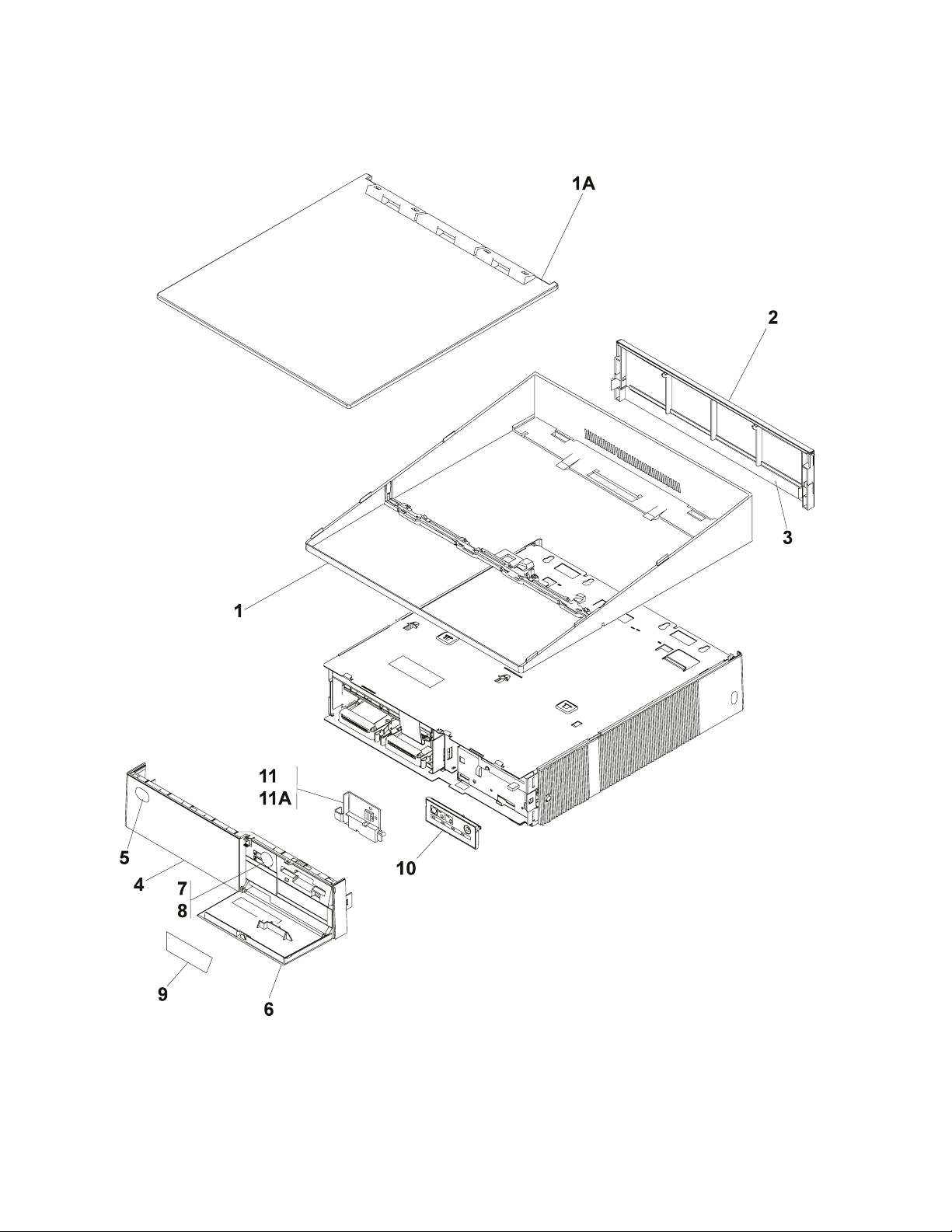
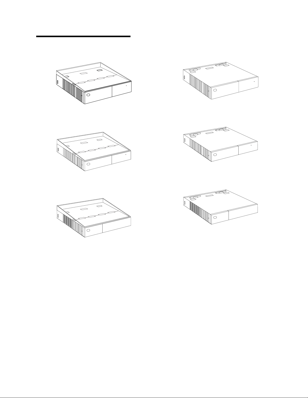
Assembly 1: System Units, 4693
2 Store Systems Parts Catalog
Page 11

Asm– Part
Index Number Units Description
1– NP System Unit Assembly, 4693
Models 212, 331, 431, 551
–1 93F1875 1 Fence Asm, Integrated
–1A 93F1860 1 Flat Top Asm, Distributed
–2 93F1896 1 Panel, Rear Cover, Modesty, Tall
Model 551 only
–2 93F1899 1 Panel, Rear Cover, Modesty, Short
Models 212, 331, 431
–3 93F1818 1 Insert, Rear Cover Modesty Panel
–4 93F1843 1 Cover Asm, Front Panel
Model 551 only
–4 93F1880 1 Cover Asm, Front Panel
Models 212, 331, 431
–5 93F1836 R Logo Plate
–6 93F1847 1 Door Asm, Front Panel Tall
Model 551 only
–6 93F1887 1 Door Asm, Front Panel Short
Models 212, 331, 431
–7 93F1855 1 Lock Barrel and Clip
Model 551 only
–8 93F1826 1 Lock Parts Kit
Model 551 only
–9 93F1866 1 Panel, Blank
Model 551 only
–10 93F1844 1 Panel Asm, Operator
Model 551 only
–10 93F1845 1 Panel Asm, Operator
Models 331, 431
–10 93F1846 1 Panel Asm, Operator
Model 212 only
–11 93F1863 1 Interlock Asm
(without Battery)
–11A 93F1135 1 Battery Asm, Standard Duration
Models 331, 431
System Unit Assemblies 3
Page 12
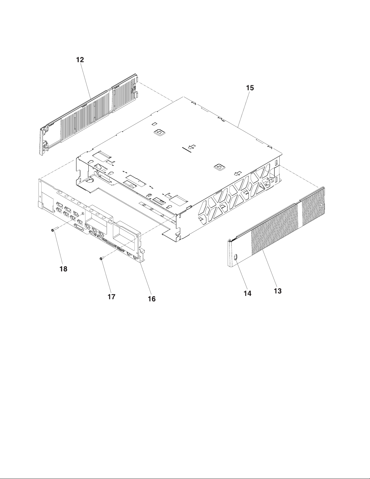
Assembly 1: (continued)
4 Store Systems Parts Catalog
Page 13
Asm– Part
Index Number Units Description
1–12 93F1842 1 Cover Asm, Right Side
Model 551 only
–12 93F1852 1 Cover Asm, Right Side
Models 212, 331, 431
–13 93F1841 1 Cover Asm, Left Side
Model 551 only
–13 93F1851 1 Cover Asm, Left Side
Models 212, 331, 431
–14 93F1902 1 Button
–15 NP Tunnel Asm
–16 93F1823 1 Panel Asm, Rear Connector
Model 212 only
–16 93F1793 1 Panel Asm, Rear Connector
Model 331 only
–16 93F1822 1 Panel Asm, Rear Connector
Model 431 only
–16 93F1821 1 Panel Asm, Rear Connector
Model 551 only
–17 61X8794 5 Screw, M3.5
–18 93F0738 1 Screw, M3.5
System Unit Assemblies 5
Page 14
Assembly 1: (continued)
25
32
33
34
31
29
26
28
27
30
36
35
DETAIL A DETAIL B
6 Store Systems Parts Catalog
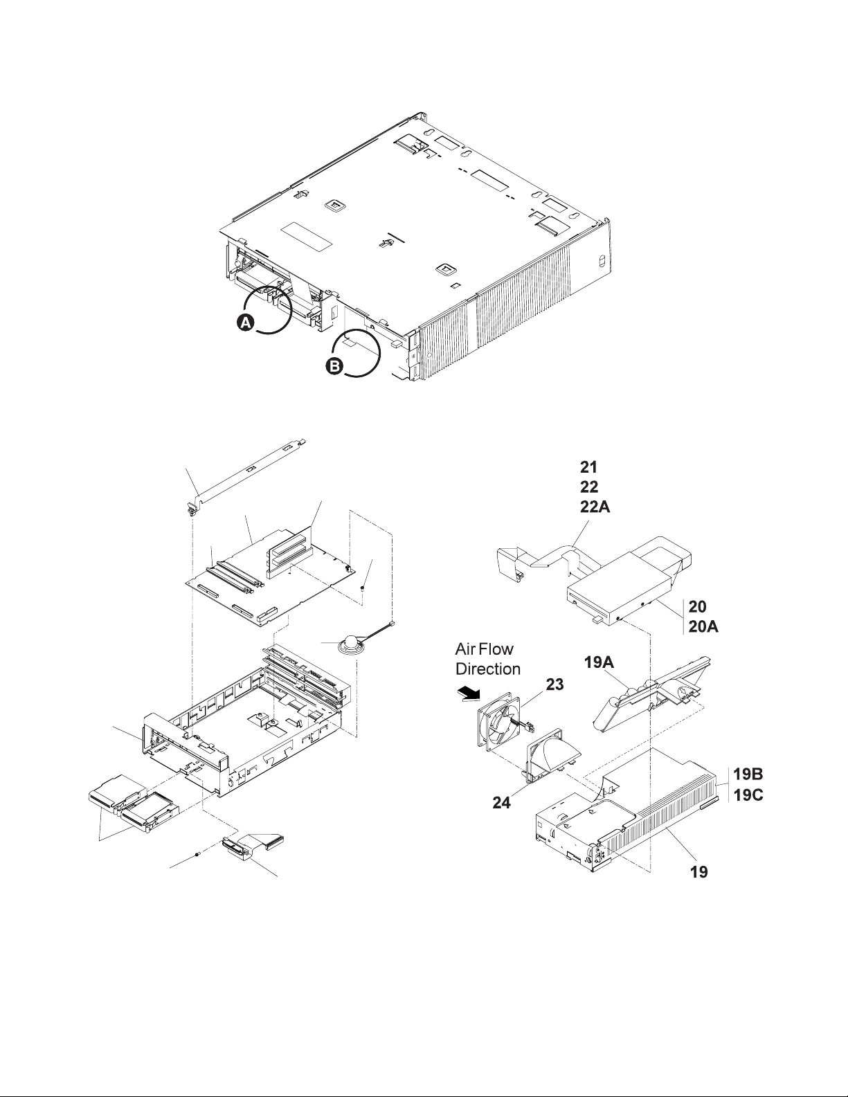
Page 15

Asm– Part
Index Number Units Description
1–19 93F1871 1 Power Supply Asm DB, Low Voltage
–19 93F1872 1 Power Supply Asm DB, High Voltage
–19A 93F1785 1 Battery Asm, Extended Duration
–19B 60G1317 1 Fuse Carrier
–19C 60G1318 1 Fuse
–20 93F1853 1 Diskette Drive Asm, 1.44 Meg, Model 551 only
–20 93F1895 1 Diskette Drive Asm, 2.88 Meg, Model 551 only
–20A 93F0658 AR Stud, M3
–21 93F1831 1 Cable, Diskette Long
–22 93F1848 1 Clip
–22A 1621176 AR Screw, Pan HD, M3 X 4
–23 93F1834 1 Fan, 80 mm, Model 551 only
–23 93F1835 1 Fan, 60 mm, Models 212, 331, 431
–24 93F1865 1 Plenum, Fan, 80 mm, Model 551
–24 93F1879 1 Plenum, Fan, 60 mm, Models 212, 331, 431
–25 93F1825 1 Card Cage Asm, Model 551 only
–25 93F1891 1 Card Cage Asm, Models 212, 331, 431
–26 93F1810 1 System Board Asm, Model 551 (PRE-CR)
–26 93F1802 1 System Board Asm, Model 431 (PRE-CR)
–26 93F1804 1 System Board Asm, Model 331 (PRE-CR)
–26 93F1803 1 System Board Asm, Model 212 only
–26 13H8923 1 System Board Asm, Model 551, CR
–26 13H8924 1 System Board Asm, Model 431, CR
–26 13H8925 1 System Board Asm, Model 331, CR
–26 42H1861 1 System Board Asm, Model 331, CR (NEW RAW CARD)
–26 13H8930 1 System Board Asm, Model 431, 486SLC2
–26 42H1860 1 System Board Asm, Model 431, N421
–27 61X8794 2 Screw, M3.5
–28 93F1830 AR Memory SIMM, 2 Meg, Models 331, 431, 551
–28 93F1840 AR Memory SIMM, 4 Meg, Models 331, 431, 551
–28 93F1850 AR Memory SIMM, 8 Meg, Models 331, 431, 551
–29 93F1790 1 Bus Adapter Card Asm, Feature, Model 551 only
–29 93F1791 1 Bus Adapter Card Asm, Feature, Models 331, 431
–30 93F1833 1 Speaker Asm,
–31 93F1819 1 Bus Adapter Retainer,
–32 93F1849 AR Fixed Disk, 80 MB, (Includes Cable and Bracket),
Model 551 only
–32 93F1877 AR Fixed Disk, 160 MB, (Includes Cable and Bracket),
Model 551 only
–33 93F1858 1 Bracket Kit, Model 551 only
–34 93F1857 1 Cable Asm, Fixed Disk, Model 551 only
–35 93F1881 1 Cable, Diskette, Short, Model 551 only
–36 78X8993 2 Screw, M3, Model 551 only
System Unit Assemblies 7
Page 16
Assembly 1: (continued)
8 Store Systems Parts Catalog
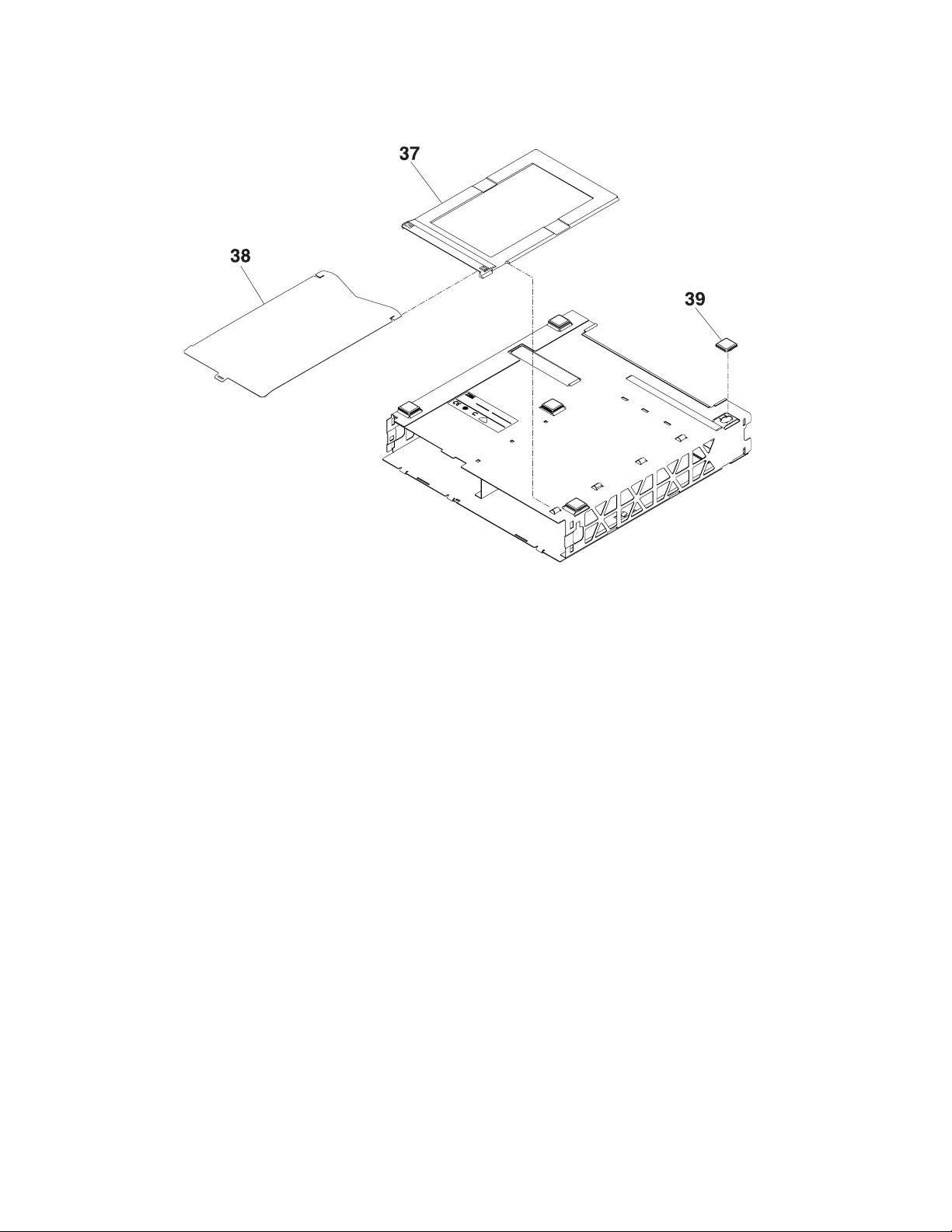
Page 17

Asm– Part
Index Number Units Description
1–37 93F1854 1 Document Tray
–38 48G9079 1 Quick Reference Card, Japan
–38 48G9085 1 Quick Reference Card, Korea
–39 93F0663 4 Rubber Foot
System Unit Assemblies 9
Page 18
Assembly 2: System Units, 4694, Models 154 and 254
10 Store Systems Parts Catalog
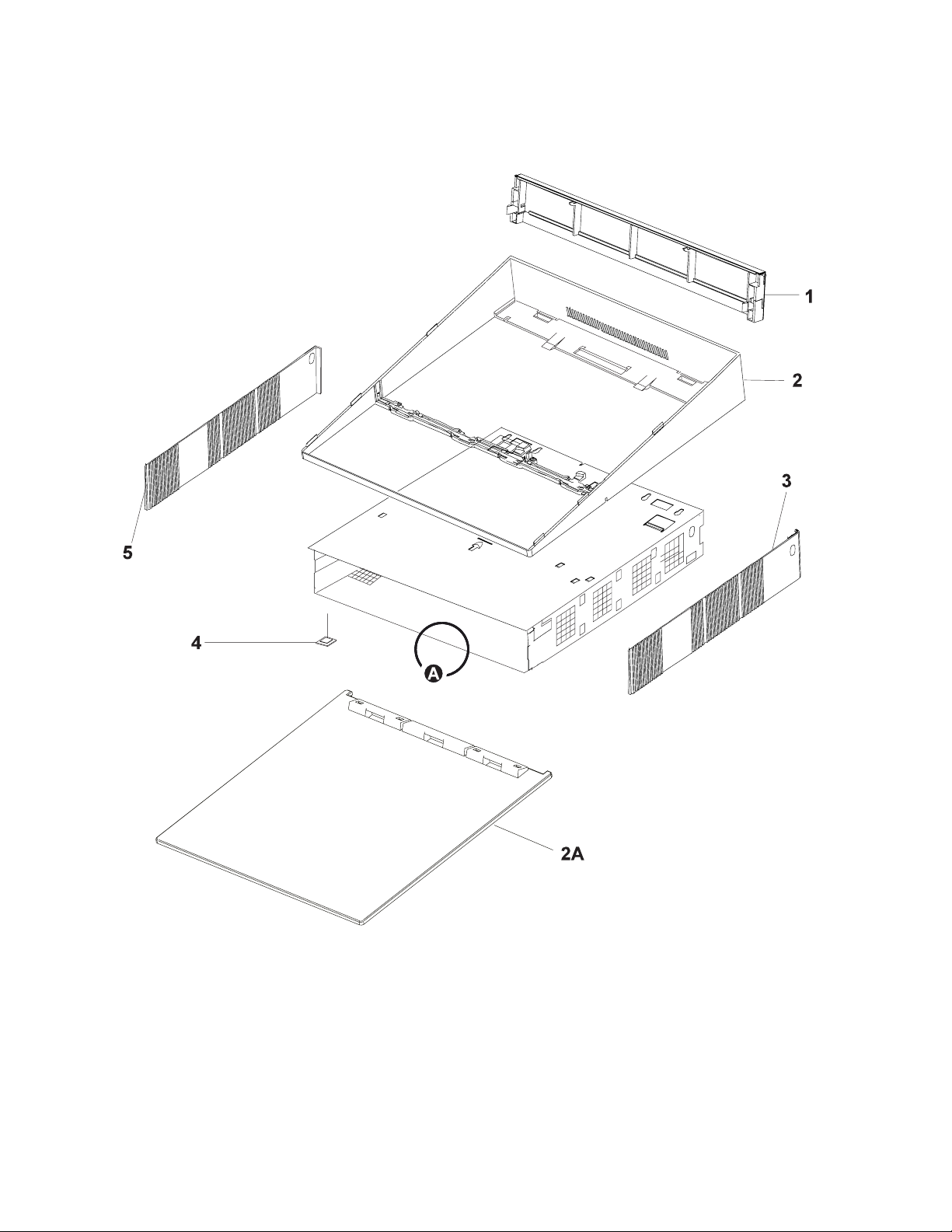
Page 19

Asm– Part
Index Number Units Description
2– NP System Unit Assembly, 4694, Model 154
–1 93F1818 1 Insert, Rear Cover Modesty Panel
–1 93F1899 1 Panel, Rear Cover, Modesty
–2 93F1875 1 Fence Asm, Integrated
–2A 93F1860 1 Flat Top Asm, Distributed
–3 93F1852 1 Cover, Right Side
–4 4 Foot (order Kit 85H4995, index 7)
–5 93F1851 1 Cover, Left Side
–6 85H4995 1 Hardware Kit, Contents:
Button, ON/OFF, White (X1)
Foot (X1), Models 001, 004, 024 only
Slot Guide, Long, Feature Card (X1)
Slot Guide, Short, Feature Card (X1)
Slot Cover, AT, Feature Card (X1)
Button, ON/OFF, White (X1)
Fuse, System Board, 5 A 125 V (X1)
Screw, Washer Head, M3 x 5 mm (X5)
Screw, Pan Head, 6-32 UNC x 4 mm (X2)
Mounting Bracket (X2)
Foot (X2), Models 041, 044, 144, 154, and 254 only
System Unit Assemblies 11
Page 20
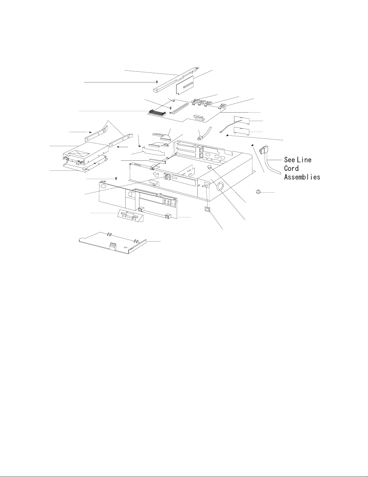
Assembly 2: (continued)
31
30
10
37
10
10
29
28
36
38
32
33
34
10
10
11
27
35
17
18
25
12
14
24
15
39
16
40
19
10
10
21
22
23
DETAIL A
12 Store Systems Parts Catalog
Page 21

Asm– Part
Index Number Units Description
2– NP System Unit Assembly, Detail A, 4694 Models 154 and 254
–10 27 Screw, Washer Head, M3 x 5 mm (order Kit 85H4995, index 6)
–11 1 Fuse, System Board, 5 A, 125 V (order Kit 85H4995, index 6)
–12 85H4975 1 Riser Card, Model 154
–12 92G9495 1 Riser Card, Model 254
–14 59G8713 1 Cable Asm, VGA Feature (includes 2 mounting screws)
–15 59G8714 2 Cable Asm, RS232 (includes 2 mounting screws)
–16 85H5004 1 System Board, Model 154 (includes Fuse, No Memory Modules,
see Index 37)
–16 85H4959 1 System Board, Model 254 (includes Fuse, No Memory Modules,
see Index 37)
–17 59G8686 1 Cable Asm, Fixed Disk Drive
–18 59G8730 1 Cable Asm, LAN, 4.3 M
–19 59G8711 1 Cover
–21 4 Foot (order Kit 85H4995, index 7)
–22 2 Spacer, System Board (order Kit 85H4995, index 6)
–23 92G9500 1 Power Supply, 24 V DBCS, 160 W, Model 154
–23 85H8526 1 Power Supply, 24 V DBCS, 197 W, Model 254
–24 1 Button, ON/OFF, White (order Kit 85H4995, index 6)
–25 92G9437 1 Front Cover Asm, (includes Door, Logo, LED Label, FDD Bezel)
–27 92G9438 1 Door, Front
–28 59G8688 1 Cover, Diskette Drive
–29 59G8819 1 Keylock Asm
–30 38H5899 1 Fixed Disk Drive, 850 MB
–30 85H4974 1 Fixed Disk Drive, 1.6 GB
–31 59G8678 1 1.44 M Diskette Drive
–32 2 Slot Guide, Feature Card (order Kit 85H4995, index 6)
–33 2 Slot Cover, Feature Card (order Kit 85H4995, index 6)
–34 4 Screw, Pan Head, 6-32 UNC x 4 mm (order Kit 85H4995)
–35 59G8687 1 Cable Asm, Diskette Drive
–36 AR Mounting Bracket, X2 or 4 (order Kit 85H4995, index 7)
–37 92G9454 4 MB Memory Module
–37 92G9455 8 MB Memory Module
–37 92G9470 16 MB Memory Module
–38 85H4970 1 Spline, Model 154
–38 85H4958 1 Spline, Model 254
–39 85H4960 1 Cable Assembly, Parallel Port, Model 254
–40 85H4973 1 Dump Switch Asm
– 92G9475 1 Button, Short, Diskette Drive (package of 10)
System Unit Assemblies 13
Page 22

14 Store Systems Parts Catalog
Page 23

Display Assemblies
“Assembly 3: Video Displays” on page 16
“Assembly 4: Character Graphics Display” on page 18
“Assembly 5: Displays, Flat Panel” on page 20
“Assembly 6: Displays, Sure Point Touch” on page 22
Copyright IBM Corp. 1996 15
Page 24

Assembly 3: Video Displays
9-Inch Video Display-Integrated
9-Inch Video Display-Distributed
16 Store Systems Parts Catalog
Page 25

Asm– Part
Index Number Units Description
3– 92G7831 1 Display, 9 Inch Video Monochrome, 1.0 m Cables
– 92G7832 1 Display, 9 Inch Video Monochrome, 2.6 m Cables
– 72H5178 1 Display, 9 Inch Video Color, 1.0 m Cables
– 72H5179 1 Display, 9 Inch Video Color, 2.6 m Cables
–1 85X7418 1 Swivel Stand, Distributed Monochrome
–1 25H4186 1 Swivel Stand, Distributed Color
The entries below are for Detail A
–2 93F1794 1 Rear Cover
–3 93F1797 1 Arm,Plug
–4 93F1789 1 Integrated Mount,Subassembly Monochrome
–5 60G4144 1 Integrated Mount Subassembly,Color
–6 93F1796 1 Casting Subassembly
–7 93F1832 4 Screw, M5
–8 60G1375 4 Retainer, Screw
Display Assemblies 17
Page 26

Assembly 4: Character Graphics Display
18 Store Systems Parts Catalog
Page 27

Asm– Part
Index Number Units Description
4–9 NP Character Graphic Display, Operator, Japan
–10 NP Character Graphic Display, Operator, Korea
–11 NP Character Graphic Display, Customer, Japan
–12 NP Character Graphic Display, Customer, Korea
–13 48G9003 1 Display, Asm, Operator, Japan
–14 48G9006 1 Display, Asm, Operator, Korea
–15 48G9004 1 Display, Asm, Customer, Japan
–16 48G9007 1 Display, Asm, Customer, Korea
–17 48G9018 1 Filter, Smoke
–18 95F3190 2 Thumb Screw
Display Assemblies 19
Page 28

Assembly 5: Displays, Flat Panel
20 Store Systems Parts Catalog
Page 29

Asm– Part
Index Number Units Description
5– 66G4206 NP Display Unit, Flat Panel, LCD, Monochrome
–1 66G4207 1 Cover Asm, Front
–2 66G4208 1 Cover Asm, Rear
–3 85G6319 1 LCD Module Asm
–4 66G4210 1 CCFL Asm, Backlight
–5 66G4211 NP Cable, LCD Module
–6 66G4222 NP Cover, CCFL
–7 66G4230 1 Card Asm, LCD Panel
– 85G6410 1 Screw and Tape Kit
– 85G6359 NP Screw, M2.2 4.5 mm (X2)
–8 66G4237 NP Screw, M3 12 mm (X2)
–9 66G4238 NP Screw, M3 8 mm (X4)
– 85G6411 NP Adhesive Tape (X2)
Display Assemblies 21
Page 30

Assembly 6: Displays, Sure Point Touch
22 Store Systems Parts Catalog
Page 31

Asm– Part
Index Number Units Description
6– 85G6304 NP Display Unit, Touch Screen, LCD, Monochrome
– 85G6307 NP Display Unit, Touch Screen, LCD, Color, 10.4 in.
–1 85G6308 1 Cover Asm, Front, Monochrome
–1 85G6347 1 Cover Asm, Front, Color, 10.4 in.
–2 85G6357 1 Card Asm, Inverter, Color, 10.4 in.
–3 85G6329 1 Cable Asm, Inverter, Color
–4 85G6328 1 Card and Cable Asm, LCD Module, Color, 10.4 in.
–5 85G6310 1 Card Asm, LCD Panel, Monochrome
–5 85G6407 1 Card Asm, LCD Panel, Color, 10.4 in.
–6 85G6309 1 Cover Asm, Rear, Monochrome
–6 85G6348 1 Cover Asm, Rear, Color, 10.4 in.
–7 85G6349 1 LCD Module Asm, Color, 10.4 in.
–8 66G4210 1 CCFL Asm, Backlight, LCD, Monochrome
–9 85G6319 1 LCD Module Asm, Monochrome
–10 85G6311 1 Touch Screen Unit Asm, Monochrome
–10 85G6341 1 Touch Screen Unit Asm, Color, 10.4 in.
– 85G6411 NP Adhesive Tape, Color (X2)
– 85G6410 1 Screw and Tape Kit
–11 85G6359 NP Screw, M2.2 4.5 mm, Color (X2)
–12 66G4237 NP Screw, M3 12 mm (X2)
–13 66G4238 NP Screw, M3 8 mm (X4)
–14 85G6411 NP Adhesive Tape, Color (X2)
– 85G6302 NS MSR Asm, Dual Head (X1)
Display Assemblies 23
Page 32

Assembly 7: Base Asm for Displays, Flat Panel and Sure Point Touch
24 Store Systems Parts Catalog
Page 33

Asm– Part
Index Number Units Description
7–10 66G4242 1 Base Asm, Display Holder
(Use for Integrated and Distributed Base Pedestals)
–11 66G4243 NP Tilt Attachment, Molded
–12 66G4244 NP Spring (X2)
–13 66G4245 NP Swivel Attachment, Molded
–14 66G4246 NP Tilt Support
–15 85G6345 NP Arm Support
–18 66G4250 1 Base Asm, Integrated Display
–15 85G6345 NP Arm Support
–16 66G4253 NP Arm Plug, Molded
–17 66G4251 NP Arm, Molded
–20 66G4252 NP Pedestal, Molded, Integrated
–21 48G9180 NP Screw, M5 20 mm
–22 66G4255 1 Base Asm, Distributed Display
–23 66G4256 NP Pedestal, Molded, Distributed
–24 66G4257 NP Plate, Base
–25 66G4258 NP Foot, Base (X4)
–26 4761085 NP Screw, M3 10 mm (X4)
– 66G4267 1 Cable Asm, Display, Flat Panel, 0.8 m (2 ft.)
– 66G4266 1 Cable Asm, Display, Flat Panel, 3.8 m (12 ft.)
Display Assemblies 25
Page 34

26 Store Systems Parts Catalog
Page 35

Keyboard Assemblies
“Assembly 8: Keyboard V” on page 28
“Assembly 11: PLU Keyboard/Display - III” on
page 34
“Assembly 9: 4685-K01 Keyboard (Keyboard-VI)”
on page 30
“Assembly 10: PC POS Keyboard” on page 32
Copyright IBM Corp. 1996 27
Page 36

Assembly 8: Keyboard V
28 Store Systems Parts Catalog
Page 37

Asm– Part
Index Number Units Description
8– 95F3275 NR Keyboard-V Unit, Japan
– 95F3276 NR Keyboard-V Unit, Korea
–1 95F3185 1 Control Card
–2 95F3182 1 Magnetic Stripe Reader
–3 95F3184 1 Top Cover Asm, Japan
–4 95F3193 1 Top Cover Asm, Korea
–5 95F3180 1 KBD Matrix Unit
–6 48G9012 AR Key Top 1X1 with Cap and Gum Dome (10 pieces)
–6 48G9013 AR Key Top 1X2 with Cap and Gum Dome (10 pieces)
–6 48G9014 1 Ten Key Set
–6 48G9015 AR Dummy Key Cover, 1X1 (10 pieces)
–6 48G9028 AR Quadruple Key Top with Cap (10 pieces)
–6 48G9029 AR Dummy Key Cover, 1X5 (5 pieces)
–7 95F3181 1 Speaker Asm
– 95F3229 NS Mode Switch Key, Manager-1, Operator-2
Keyboard Assemblies 29
Page 38

Assembly 9: 4685-K01 Keyboard (Keyboard-VI)
30 Store Systems Parts Catalog
Page 39

Asm– Part
Index Number Units Description
9– 85G3987 NR POS Keyboard Unit, Keyboard-VI
–1 85G3992 1 Top Cover, Asm
–2 85G3962 1 Control Card Asm
–3 85G3964 1 Indicator Card Asm
–4 85G3965 1 Mode Key Switch Asm
–5 85G3985 1 Speaker Asm
–6 85G3984 1 MSR Cable
–7 85G3953 1 Bottom Cover Asm
–8 95F3182 1 Magnetic Stripe Reader (MSR)
– 48G9012 NS Key Top 1X1 with Cap and Gum Dome (10 pieces)
– 48G9013 NS Key Top 1X2 with Cap and Gum Dome (10 pieces)
– 48G9014 NS Ten Key Set
– 48G9015 NS Dummy Key Cover, 1X1 (10 pieces)
– 48G9028 NS Quadruple Key Top with Cap (10 pieces)
– 48G9029 NS Dummy Key Cover, 1X5 (5 pieces)
– 85G6424 NS Mode Switch Key, Manager-2, Operator-2, Administrator-2
Keyboard Assemblies 31
Page 40

Assembly 10: PC POS Keyboard
32 Store Systems Parts Catalog
Page 41

Asm– Part
Index Number Units Description
10– 93F1930 NR Retail Alphanumeric POS Keyboard w/Card Reader 4693, Japan
– 93F1929 NR Retail Alphanumeric POS Keyboard w/Card Reader 4693, Korea
–1 93F1778 1 Cover Asm, Top, Japan
–2 93F1777 1 Cover Asm, Top, Korea
–3 93F1766 1 Magnetic Strip Reader
–4 60G4142 AR Screw (Order Kit #93F0254)
–5 93F1765 1 Card Asm, Keyboard Logic
–6 60G4142 AR Screw
–7 09F3394 1 Test Card, MSR (Not Illustrated)
Accessory Parts:
Key Cap Kits
93F1950 Key Cap, Standard (25 pieces)
93F1952 Key Cap, Tall-Single Wide (25 pieces)
Keyboard Assemblies 33
Page 42

Assembly 11: PLU Keyboard/Display - III
34 Store Systems Parts Catalog
Page 43

Asm– Part
Index Number Units Description
11– 95F3277 NR PLU Keyboard/Display-III unit, Japan
– 95F3281 NR PLU Keyboard/Display-III unit, Korea
–1 95F3189 1 Control Card
–2 95F3278 1 Bottom Cover Asm, Japan
–3 48G9027 1 Bottom Cover Asm, Korea
–4 95F3195 1 Top Cover Asm, Japan
–5 95F3196 1 Top Cover Asm, Korea
–6 95F3245 1 Matrix Unit
–7 48G9012 AR Key Top 1X1 with Cap and Gum Dome (10 pieces)
–7 48G9013 AR Key Top 1X2 with Cap and Gum Dome (10 pieces)
–7 48G9015 AR Dummy Key Cover, 1X1 (10 pieces)
–7 48G9028 AR Quadruple Key Top with Cap (10 pieces)
–7 48G9029 AR Dummy Key Cover, 1X5 (5 pieces)
–7 48G9014 1 Ten Key Set
–8 95F3188 1 PLU Keyboard/Display Asm w/cover, Japan
–9 48G9021 1 PLU Keyboard/Display Asm w/cover, Korea
Cable Asm.:
48G9020, Character/Graphics Display, PLU-III S-I/O Cable
(1.8m)
95F3191, Character/Graphics Display, PLU-III S-I/O Cable
(3.8m)
Keyboard Assemblies 35
Page 44

Assembly 12: PLU Extension Box
36 Store Systems Parts Catalog
Page 45

Asm– Part
Index Number Units Description
12–1 95F3227 1 PLU Extension Box, Japan
–1 95F3228 1 PLU Extension Box, Korea
Cable Asm:
95F3280, PLU Extension S-I/O cable, (3.8M) (POSS)
Keyboard Assemblies 37
Page 46

38 Store Systems Parts Catalog
Page 47

Cash Drawer Assemblies
“Assembly 13: Cash Drawer Assembly” on
page 40
“Assembly 13: Cash Drawer Assembly” on
page 40
Copyright IBM Corp. 1996 39
Page 48

Assembly 13: Cash Drawer Assembly
3
2
1
4
12
10
18
13
14
5
15
11
7
8
16
19
9
17
6
40 Store Systems Parts Catalog
Page 49

Asm– Part
Index Number Units Description
13– NP Cash Drawer Assembly
–1 93F1917 1 Cover, Top
–2 93F1780 1 Cash Drawer, Adapter Plate
–3 93F1779 2 Screw, Mounting, M5 (Thumbscrew)
–4 93F1901 1 Panel, Rear
–5 93F1902 2 Button
–6 93F1908 1 Drawer
–7 93F1897 1 Stop, Document
–8 42H3785 1 Lock, Clip
–9 93F1906 1 Slide, Left
–10 93F1907 1 Slide, Right
–11 1621594 6 Screw
–12 42H3783 1 Latch Asm
–13 93F1915 1 Propulsion Spring
–14 93F1916 1 Card Asm
–15 93F1913 1 Cam, Pawl and Spring Kit
–16 93F1904 1 Base
–17 93F1909 1 Lock, Cash Drawer with Lock only
–18 93F1905 1 Actuator, Cash Drawer with Lock only
–19 76X0200 NR Cash Drawer Flip Top
Cash Drawer Assemblies 41
Page 50

Assembly 14: Integrated Slant Top Asm
42 Store Systems Parts Catalog
Page 51

Asm– Part
Index Number Units Description
14–1 93F0701 1 Frame Asm, DBCS
–2 74F6375 NP Frame, Molded, DBCS
–3 93F0708 NP Latch
–4 93F0707 NP Linkage Asm
–5 93F0709 NP Button, Actuator, Molded
Cash Drawer Assemblies 43
Page 52

Assembly 15: Integrated Filler Panel Kit, Character/Graphics Display
44 Store Systems Parts Catalog
Page 53

Asm– Part
Index Number Units Description
15–1 93F0720 R Filler Panel-1 Asm
–2 48G9180 NP Screw, M5
–3 93F0719 R Filler Panel-1 molded
–4 93F0721 NP Filler Plug 1, Blank
–5 93F0722 NP Filler Plug 2, Blank
–6 93F0724 NP Sponge Holder
–7 93F0726 NP Sponge (Accessory parts)
–8 93F0725 NP Side Holder
Cash Drawer Assemblies 45
Page 54

Assembly 16: Integrated Filler Panel Kits, Video Display
46 Store Systems Parts Catalog
Page 55

Asm– Part
Index Number Units Description
16–1 93F0723 R Filler Panel-2 CRT Asm
–2 59G9099 NP Filler Plug 1, CRT
–3 48G9181 NR Screw, M5
–4 93F0721 NP Filler Plug 1, Blank
–5 93F0722 NP Filler Plug 2, Blank
–6 93F0724 NP Sponge Holder
–7 93F0726 NP Sponge (Accessory parts)
–8 93F0725 NP Side Holder
–9 93F0729 R Filler Panel-2 Molded
Cash Drawer Assemblies 47
Page 56

Assembly 17: Integrated Printer Filler Panel
Filler Panel for 4689-701 Receipt/Journal Printer
Filler Panel for 4689-301 Receipt/Journal Printer
48 Store Systems Parts Catalog
Page 57

Asm– Part
Index Number Units Description
17– NP Filler Panel-CRJ, Asm
–1 59G9143 R Filler Panel, 4689-701 R/J Printer
–2 84G2872 R Filler Panel, 4689-301 R/J Printer
Cash Drawer Assemblies 49
Page 58

Assembly 18: Integrated Tape Holder Kits
50 Store Systems Parts Catalog
Page 59

Asm– Part
Index Number Units Description
18–1 59G9136 NP Tape Holder Asm
–2 59G9137 NP Tape Holder Base
–3 59G9138 NP Tape Holder Blade (Accessory parts)
–4 6237379 NP Screw M2.5
–5 59G9139 NP Tape Holder Wheel (Accessory parts)
Cash Drawer Assemblies 51
Page 60

Assembly 19: Cash Drawer Integrated I/O Adapter Plate Assemblies
52 Store Systems Parts Catalog
Page 61

Asm– Part
Index Number Units Description
19–1 74F6249 R Cash Drawer Adapter Plate Asm
–2 74F6248 NP Cash Drawer Adapter Plate
–3 1621230 NP Screw, M6 x 12, Slotted
Cash Drawer Assemblies 53
Page 62

Assembly 20: Till Cover Assemblies
54 Store Systems Parts Catalog
Page 63

Asm– Part
Index Number Units Description
20– 74F6440 R Till Cover Asm
–1 74F6443 NP Plate
–2 74F6441 NP Till Cover
–3 74F6442 NP Key Lock Asm
Cash Drawer Assemblies 55
Page 64

Assembly 21: Till Box Assemblies
56 Store Systems Parts Catalog
Page 65

Asm– Part
Index Number Units Description
21– 74F6430 R Till Box Asm
–1 74F6431 NP Till Box
–2 74F6432 3 Retainer Asm
–3 74F6435 NP Plate
–4 74F6436 NP Coin Till-1
–5 74F6437 NP Coin Till-2
Cash Drawer Assemblies 57
Page 66

Assembly 22: Line Cord and Cable Assemblies
Asm– Part
Index Number Units Description
LINE CORD ASSEMBLIES
22–1 34G0229 AR Line Cord Asm, 2.8m Non-Locking, Japan (4693 only)
–2 34G0230 AR Line Cord Asm, 4.3m Non-Locking, Japan
–3 94X2048 AR Line Cord Asm, 4.3m Locking, Japan
–4 13F9977 AR Line Cord Asm, 4.3m Non-Locking, Korea
–5 85G6261 AR Line Cord Asm, 4.3m Locking, White, Japan
–5 34G0241 AR Video Line Cord, 1.0m, Japan (4693 only)
–6 34G0243 AR Video Line Cord, 4.3m, Japan (4693 only)
DBCS I/O DEVICES
–7 25F6341 1 Cable Asm, PC POS keyboard, 0.715m
–8 25F6342 1 Cable Asm, PC POS keyboard, 3.8m
–9 59G9146 1 Cable Asm, Keyboard-V, 0.48m
–10 6457727 1 Cable Asm, Keyboard-V, 1.8m
–11 6316857 1 Cable Asm, Keyboard-V, 3.8m
–12 95F3280 1 Cable Asm, PLU-Extension (POSS), 3.8m
–13 95F3192 1 Cable Asm, Character Graphics/Display, 0.8m
–14 48G9020 1 Cable Asm, Character Graphics/Display, 1.8m
–15 95F3191 1 Cable Asm, Character Graphics/Display, 3.8m
–16 6316831 1 Cable Asm, Cash Drawer, 0.4m
–17 38F8813 1 Cable Asm, Cash Drawer, 1.4m
–18 6316832 1 Cable Asm, Cash Drawer, 3.8m
–19 96X5027 1 Cable Asm, Video Display, Signal, Distributed
–20 85G3927 AR T-connector
SERIAL I/O CABLES
–20 6316837 1 Cable Asm, SIO, 6m/20ft, SDL
–21 6316838 1 Cable Asm, SIO, 20m/66ft, SDL
–22 4783789 1 Cable Asm, SIO, 1pr, 4m/13ft
–23 93F0808 1 S-loop cable
58 Store Systems Parts Catalog
Page 67

Assembly 23: Option Adapter Cards
Asm– Part
Index Number Units Description
Supported Adapter
23–1 25H4247 Adapter/A, Store Loop (Microchannel), 4693
–2 79F1487 Dual Store Loop Adapter/A (Microchannel), Japan only
–3 85G6414 Adapter/A, Flat Panel Display (Microchannel), except for N421
–4 26H7098 Adapter, Flat Panel Display (ISA)
–5 92G7923 Adapter/A, Flat Panel Display (Microchannel) with Flat Cable, N421
only
–6 85H8102 Adapter, 4694, Store Loop
Cash Drawer Assemblies 59
Page 68

Assembly 24: Locks, Tools, and Diskettes
Asm– Part
Index Number Units Description
4693 and 4694
24–1 33G3352 NS Lock, Style 9952
–1 33G3353 NS Lock, Style 9953
–1 33G3354 NS Lock, Style 9954
–1 33G3355 NS Lock, Style 9955
–1 33G3356 NS Lock, Style 9956
–1 33G3357 NS Lock, Style 9957
–1 33G3358 NS Lock, Style 9958
–1 33G3359 NS Lock, Style 9959
–1 33G3360 NS Lock, Style 9960
–1 33G3361 NS Lock, Style 9961
–1 4783923 NS Lock, Blank
–2 4783922 NS Lock Installation and Removal Tool Kit
4693
–3 48G9109 NS Medialess Support Diskette (Japanese)
–4 48G9110 NS Medialess Support Diskette (Korean)
–5 48G9141 NS Model 551 Reference and Diagnostic Diskette Asm (Japanese)
–6 48G9142 NS Model 551 Reference and Diagnostic Diskette Asm (Korean)
60 Store Systems Parts Catalog
Page 69

Part Number Index
Part Asm–
Number Index Page
09F3394 10–7 33
13F9977 22–4 58
13H8923 1–26 7
13H8924 1–26 7
13H8925 1–26 7
13H8930 1–26 7
1621176 1–22A 7
1621230 19–3 53
1621594 13–11 41
25F6341 22–7 58
25F6342 22–8 58
25H4186 3–1 17
25H4247 23–1 59
26H7098 23–4 59
33G3352 24–1 60
33G3353 24–1 60
33G3354 24–1 60
33G3355 24–1 60
33G3356 24–1 60
33G3357 24–1 60
33G3358 24–1 60
33G3359 24–1 60
33G3360 24–1 60
33G3361 24–1 60
34G0229 22–1 58
34G0230 22–2 58
34G0241 22–5 58
34G0243 22–6 58
38F8813 22–17 58
38H5899 2–30 13
42H1860 1–26 7
42H1861 1–26 7
42H3783 13–12 41
42H3785 13–8 41
4761085 7–26 25
4783789 22–22 58
4783922 24–2 60
4783923 24–1 60
48G9003 4–13 19
48G9004 4–15 19
48G9006 4–14 19
48G9007 4–16 19
48G9012 8–6 29
9–31
11–7 35
48G9013 8–6 29
9–31
11–7 35
48G9014 8–6 29
9–31
11–7 35
48G9015 8–6 29
9–31
Part Asm–
Number Index Page
48G9015 continued
11–7 35
48G9018 4–17 19
48G9020 22–14 58
48G9021 11–9 35
48G9027 11–3 35
48G9028 8–6 29
9–31
11–7 35
48G9029 8–6 29
9–31
11–7 35
48G9079 1–38 9
48G9085 1–38 9
48G9109 24–3 60
48G9110 24–4 60
48G9141 24–5 60
48G9142 24–6 60
48G9180 7–21 25
15–2 45
48G9181 16–3 47
59G8678 2–31 13
59G8686 2–17 13
59G8687 2–35 13
59G8688 2–28 13
59G8711 2–19 13
59G8713 2–14 13
59G8714 2–15 13
59G8730 2–18 13
59G8819 2–29 13
59G9099 16–2 47
59G9136 18–1 51
59G9137 18–2 51
59G9138 18–3 51
59G9139 18–5 51
59G9143 17–1 49
59G9146 22–9 58
60G1317 1–19B 7
60G1318 1–19C 7
60G1375 3–8 17
60G4142 10–4 33
10–6 33
60G4144 3–5 17
61X8794 1–17 5
1–27 7
6237379 18–4 51
6316831 22–16 58
6316832 22–18 58
6316837 22–20 58
6316838 22–21 58
6316857 22–11 58
6457727 22–10 58
66G4206 5– 21
Part Asm–
Number Index Page
66G4207 5–1 21
66G4208 5–2 21
66G4210 5–4 21
6–8 23
66G4211 5–5 21
66G4222 5–6 21
66G4230 5–7 21
66G4237 5–8 21
6–12 23
66G4238 5–9 21
6–13 23
66G4242 7–10 25
66G4243 7–11 25
66G4244 7–12 25
66G4245 7–13 25
66G4246 7–14 25
66G4250 7–18 25
66G4251 7–17 25
66G4252 7–20 25
66G4253 7–16 25
66G4255 7–22 25
66G4256 7–23 25
66G4257 7–24 25
66G4258 7–25 25
66G4266 7– 25
66G4267 7– 25
72H5178 3– 17
72H5179 3– 17
74F6248 19–2 53
74F6249 19–1 53
74F6375 14–2 43
74F6430 21– 57
74F6431 21–1 57
74F6432 21–2 57
74F6435 21–3 57
74F6436 21–4 57
74F6437 21–5 57
74F6440 20– 55
74F6441 20–2 55
74F6442 20–3 55
74F6443 20–1 55
76X0200 13–19 41
78X8993 1–36 7
79F1487 23–2 59
84G2872 17–2 49
85G3927 22–20 58
85G3953 9–7 31
85G3962 9–2 31
85G3964 9–3 31
85G3965 9–4 31
85G3984 9–6 31
85G3985 9–5 31
85G3987 9– 31
Part Asm–
Number Index Page
85G3992 9–1 31
85G6261 22–5 58
85G6302 6– 23
85G6304 6– 23
85G6307 6– 23
85G6308 6–1 23
85G6309 6–6 23
85G6310 6–5 23
85G6311 6–10 23
85G6319 5–3 21
6–9 23
85G6328 6–4 23
85G6329 6–3 23
85G6341 6–10 23
85G6345 7–15 25
7–15 25
85G6347 6–1 23
85G6348 6–6 23
85G6349 6–7 23
85G6357 6–2 23
85G6359 5– 21
6–11 23
85G6407 6–5 23
85G6410 5– 21
6–23
85G6411 5– 21
6–23
6–14 23
85G6414 23–3 59
85G6424 9– 31
85H4958 2–38 13
85H4959 2–16 13
85H4960 2–39 13
85H4970 2–38 13
85H4973 2–40 13
85H4974 2–30 13
85H4975 2–12 13
85H4995 2–6 11
85H5004 2–16 13
85H8102 23–6 59
85H8526 2–23 13
85X7418 3–1 17
92G7831 3– 17
92G7832 3– 17
92G7923 23–5 59
92G9437 2–25 13
92G9438 2–27 13
92G9454 2–37 13
92G9455 2–37 13
92G9470 2–37 13
92G9475 2– 13
92G9495 2–12 13
92G9500 2–23 13
Copyright IBM Corp. 1996 61
Page 70

Part Asm–
Number Index Page
93F0658 1–20A 7
93F0663 1–39 9
93F0701 14–1 43
93F0707 14–4 43
93F0708 14–3 43
93F0709 14–5 43
93F0719 15–3 45
93F0720 15–1 45
93F0721 15–4 45
16–4 47
93F0722 15–5 45
16–5 47
93F0723 16–1 47
93F0724 15–6 45
16–6 47
93F0725 15–8 45
16–8 47
93F0726 15–7 45
16–7 47
93F0729 16–9 47
93F0738 1–18 5
93F0808 22–23 58
93F1135 1–11A 3
93F1765 10–5 33
93F1766 10–3 33
93F1777 10–2 33
93F1778 10–1 33
93F1779 13–3 41
93F1780 13–2 41
93F1785 1–19A 7
93F1789 3–4 17
93F1790 1–29 7
93F1791 1–29 7
93F1793 1–16 5
93F1794 3–2 17
93F1796 3–6 17
93F1797 3–3 17
93F1802 1–26 7
93F1803 1–26 7
93F1804 1–26 7
93F1810 1–26 7
93F1818 1–3 3
2–1 11
93F1819 1–31 7
93F1821 1–16 5
93F1822 1–16 5
93F1823 1–16 5
93F1825 1–25 7
93F1826 1–8 3
93F1830 1–28 7
93F1831 1–21 7
93F1832 3–7 17
93F1833 1–30 7
93F1834 1–23 7
93F1835 1–23 7
93F1836 1–5 3
93F1840 1–28 7
Part Asm–
Number Index Page
93F1841 1–13 5
93F1842 1–12 5
93F1843 1–4 3
93F1844 1–10 3
93F1845 1–10 3
93F1846 1–10 3
93F1847 1–6 3
93F1848 1–22 7
93F1849 1–32 7
93F1850 1–28 7
93F1851 1–13 5
2–5 11
93F1852 1–12 5
2–3 11
93F1853 1–20 7
93F1854 1–37 9
93F1855 1–7 3
93F1857 1–34 7
93F1858 1–33 7
93F1860 1–1A 3
2–2A 11
93F1863 1–11 3
93F1865 1–24 7
93F1866 1–9 3
93F1871 1–19 7
93F1872 1–19 7
93F1875 1–1 3
2–2 11
93F1877 1–32 7
93F1879 1–24 7
93F1880 1–4 3
93F1881 1–35 7
93F1887 1–6 3
93F1891 1–25 7
93F1895 1–20 7
93F1896 1–2 3
93F1897 13–7 41
93F1899 1–2 3
2–1 11
93F1901 13–4 41
93F1902 1–14 5
13–5 41
93F1904 13–16 41
93F1905 13–18 41
93F1906 13–9 41
93F1907 13–10 41
93F1908 13–6 41
93F1909 13–17 41
93F1913 13–15 41
93F1915 13–13 41
93F1916 13–14 41
93F1917 13–1 41
93F1929 10– 33
93F1930 10– 33
94X2048 22–3 58
95F3180 8–5 29
95F3181 8–7 29
Part Asm–
Number Index Page
95F3182 8–2 29
9–8 31
95F3184 8–3 29
95F3185 8–1 29
95F3188 11–8 35
95F3189 11–1 35
95F3190 4–18 19
95F3191 22–15 58
95F3192 22–13 58
95F3193 8–4 29
95F3195 11–4 35
95F3196 11–5 35
95F3227 12–1 37
95F3228 12–1 37
95F3229 8– 29
95F3245 11–6 35
95F3275 8– 29
95F3276 8– 29
95F3277 11– 35
95F3278 11–2 35
95F3280 22–12 58
95F3281 11– 35
96X5027 22–19 58
62 Store Systems Parts Catalog
Page 71

Page 72

IBM
Printed in Japan
G135-4 29- 1
 Loading...