

Page 1

Store Systems:
ÉÂÔ
Installation and Operation Guide for
Point-of-Sale Input/Output Devices
GA27-4028-01
Created February 23, 1997
Page 2

Page 3

Store Systems:
ÉÂÔ
Installation and Operation Guide for
Point-of-Sale Input/Output Devices
GA27-4028-01
Created February 23, 1997
Page 4

Note
Before using this information and the product it supports, be sure to read the general information under “Notices” on page v.
Translations of the safety notices are found in the
60G1330, that is shipped with the point-of-sale terminal if required.
IBM 4693/4694 Point of Sale Terminals: Product Safety Information
, P/N
Created February 23, 1997
Second Edition (November 1995)
This is the second edition of the
edition replaces and obsoletes IBM Store Systems: Installation and Operation Guide for Point-of-Sale Input/Output Devices,
GA27-4028-00.
Order publications through your IBM representative or the IBM branch office serving your locality. Publications are not stocked at the
address given below.
Forms for readers’ comments appear at the back of this publication. If the forms have been removed, address your comments to:
IBM Corporation, Information Development, Department CJMA
PO Box 12195
Research Triangle Park, North Carolina 27709-9990
USA
When you send information to IBM, you grant IBM a nonexclusive right to use or distribute the information in any way it believes
appropriate without incurring any obligation to you.
Copyright International Business Machines Corporation 1994, 1995. All rights reserved.
Note to U.S. Government Users — Documentation related to restricted rights — Use, duplication or disclosure is subject to
restrictions set forth in GSA ADP Schedule Contract with IBM Corp.
IBM* Store Systems: Installation and Operation Guide for Point-of-Sale Input/Output Devices
. This
Page 5

Created February 23, 1997
Contents
Notices . . . . . . . . . . . . . . . . . . . . . . . . . . . . . . . . . . . . . . . . . . . . . . . . . . . . . . . . v
Trademarks . . . . . . . . . . . . . . . . . . . . . . . . . . . . . . . . . . . . . . . . . . . . . . . . . . . v
General Safety Information ............................................ vi
Electronic Emission Notices .......................................... vii
Preface . . . . . . . . . . . . . . . . . . . . . . . . . . . . . . . . . . . . . . . . . . . . . . . . . . . . . . . viii
Related Publications . . . . . . . . . . . . . . . . . . . . . . . . . . . . . . . . . . . . . . . . . . . . . . viii
Related Diskettes . . . . . . . . . . . . . . . . . . . . . . . . . . . . . . . . . . . . . . . . . . . . . . . . viii
Summary of Changes .............................................. ix
Chapter 1. Installing Input/Output Devices ................................ 1-1
Installing I/O Devices .............................................. 1-3
Installing the Cash Drawer and the System Unit ............................. 1-5
Installing the Compact Cash Drawer Coin Roll Cutter .......................... 1-6
Using the Compact Cash Drawer Coin Roll Cutter ............................ 1-6
Installing the 9-Inch Video Display ..................................... 1-7
Installing an Integrated Keyboard ...................................... 1-7
Installing the Fillers .............................................. 1-8
Installing the Printer .............................................. 1-9
Securing I/O Devices to the System Unit ................................ 1-10
Installing the Alphanumeric Display .................................... 1-10
Installing the 40-Character Liquid Crystal Display ........................... 1-11
Install 40-Character Vacuum Fluorescent Display II .......................... 1-12
Installing the Character Graphics Display ................................ 1-12
Installing the Shopper Display ....................................... 1-13
Installing a Flat Panel or Sure Point Touch Display .......................... 1-14
Installing the Distribution Kit ........................................ 1-15
Installing the Integration Kit ........................................ 1-15
Installing the Optional MSR Kit on the Sure Point Touch Display .................. 1-16
Installing the Signature Capture Device ................................... 1-17
Installing the RS232 Interface Model ................................... 1-17
Installing the RS485 Interface Model ................................... 1-17
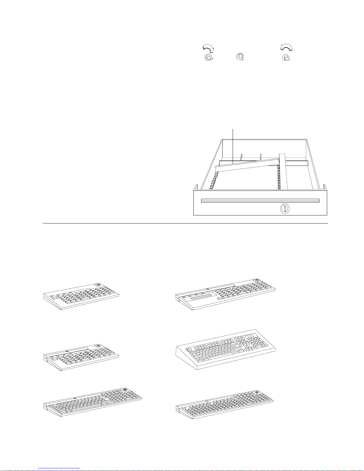
Installing and Removing Keylocks ...................................... 1-18
Preparing to Install a Lock or a Blank Lock Insert ........................... 1-18
Installing a Lock Insert ........................................... 1-19
Removing a Lock Insert .......................................... 1-20
Installing a Blank Lock Insert ....................................... 1-20
Removing a Blank Lock Insert ....................................... 1-20
Installing the System Unit Rear Cover .................................. 1-21
Chapter 2. Operating Point-of-Sale I/O Devices ............................. 2-1
Displays . . . . . . . . . . . . . . . . . . . . . . . . . . . . . . . . . . . . . . . . . . . . . . . . . . . . . . 2-2
Adjusting the Controls on Video Displays ................................. 2-3
Cash Drawers . . . . . . . . . . . . . . . . . . . . . . . . . . . . . . . . . . . . . . . . . . . . . . . . . . . 2-4
Keylock Positions . . . . . . . . . . . . . . . . . . . . . . . . . . . . . . . . . . . . . . . . . . . . . . . 2-5
Document Storage Area Under Cash Till ................................. 2-5
Keyboards . . . . . . . . . . . . . . . . . . . . . . . . . . . . . . . . . . . . . . . . . . . . . . . . . . . . . 2-5
Function Keys . . . . . . . . . . . . . . . . . . . . . . . . . . . . . . . . . . . . . . . . . . . . . . . . . 2-6
Manager’s Keylock . . . . . . . . . . . . . . . . . . . . . . . . . . . . . . . . . . . . . . . . . . . . . . 2-6
Keyboard Lights (Status Indicators) ..................................... 2-7
Copyright IBM Corp. 1994, 1995 iii
Page 6

Created February 23, 1997
Printers . . . . . . . . . . . . . . . . . . . . . . . . . . . . . . . . . . . . . . . . . . . . . . . . . . . . . . 2-7
Operating the Model 2 Point of Sale Printer ................................. 2-8
Opening/Closing the Document Insert Station ............................... 2-8
Inserting Documents in the Model 2 Printer ................................ 2-9
Advancing the Journal Paper on the Model 2 Printer .......................... 2-10
Advancing the Customer Receipt ..................................... 2-10
Tearing the Customer Receipt ....................................... 2-10
Unlocking the Journal Cover ........................................ 2-10
Testing the Model 2 Printer ........................................ 2-11
Operating the Model 3 or 4 Point of Sale Printer .............................. 2-11
Inserting Documents in the Model 3 or 4 Printer ............................ 2-11
Aligning the Print Line on an Inserted Document ............................ 2-13
Advancing the Customer Receipt Paper or Journal Paper ....................... 2-13
Unlocking the Journal Cover ........................................ 2-13
Testing the Model 3 or 4 Printer ..................................... 2-14
Model 4A Point of Sale Printer ........................................ 2-15
Model 3R and Model 4R Point of Sale Printers .............................. 2-15
Operating the Model 3R and Model 4R Printer ............................. 2-16
Entering Data at Your Terminal ........................................ 2-18
Operating Card Readers and Bar Code Readers ............................ 2-18
Cleaning the Card Reader ......................................... 2-19
Entering Data with the Hand-Held Bar Code Readers ......................... 2-19
Operating the Signature Capture Device .................................. 2-20
Signature Submission . . . . . . . . . . . . . . . . . . . . . . . . . . . . . . . . . . . . . . . . . . . . 2-20
Replacing the Pen Refill – Version 1 ................................... 2-20
Replacing the Pen Refill – Version 2 ................................... 2-20
Appendix A. Expendable Supplies and Replaceable Parts ...................... A-1
How to Order Expendable Supplies ...................................... A-1
Ribbon Cartridge for Point-of-Sale Printers ................................ A-1
Roll Paper for Point-of-Sale Printers .................................... A-2
Additional Forms for Point-of-Sale Printer Model 2 ............................ A-3
Additional Forms for Point-of-Sale Printer Model 3 or 4 ......................... A-4
Appendix B. Operator and Programmer Information .......................... B-1
Operator Techniques for the Point-of-Sale Printers ............................. B-1
Application Program Techniques for Point-of-Sale Printers ......................... B-1
Appendix C. Display Configurations and Controls ........................... C-1
Flat Panel Display Controls ........................................... C-1
Flat Panel Display Sleep Control ...................................... C-2
Sure Point Touch Display Controls ....................................... C-3
Sure Point Touch Display Beeper Controls ................................ C-3
Touch Display Sleep Control ........................................ C-4
Sure Point Touch Display Calibration .................................... C-5
Index . . . . . . . . . . . . . . . . . . . . . . . . . . . . . . . . . . . . . . . . . . . . . . . . . . . . . . . . X-1
iv Installation and Operation for POS I/O Devices
Page 7

Created February 23, 1997
Notices
The following paragraph does not apply to the United Kingdom or any country where such provisions are
inconsistent with local law: INTERNATIONAL BUSINESS MACHINES CORPORATION PROVIDES THIS
PUBLICATION "AS IS" WITHOUT WARRANTY OF ANY KIND, EITHER EXPRESS OR IMPLIED,
INCLUDING, BUT NOT LIMITED TO THE IMPLIED WARRANTIES OF MERCHANTABILITY OR
FITNESS FOR A PARTICULAR PURPOSE. Some states do not allow disclaimer of express or implied
warranties in certain transactions, therefore, this statement may not apply to you.
References in this publication to IBM products, programs, or services do not imply that IBM intends to
make these available in all countries in which IBM operates. Any reference to an IBM product, program,
or service is not intended to state or imply that only IBM’s product, program, or service may be used. Any
functionally equivalent product, program, or service that does not infringe any of IBM’s intellectual property
rights maybe used instead of the IBM program, product, or service. Evaluation and verification of
operation in conjunction with other products, except those expressly designated by IBM, are the user’s
responsibility.
IBM may have patents or pending patent applications covering subject matter in this document. The
furnishing of this document does not give you any license to these patents. You can send license
inquiries, in writing, to the IBM Director of Licensing, IBM Corporation, 500 Columbus Avenue, Thornwood,
NY 10594 USA.
Trademarks
The following terms, denoted by an asterisk (*) in this publication, are trademarks of the IBM Corporation
in the United States or other countries or both:
IBM PS/2 Sure Point Touch Screen
The following terms, denoted by a double asterisk (**) in this publication, are trademarks of other
companies:
Checkmate Checkmate Electronics Inc.
Cross A.T.X International Inc.
Contents v
Page 8

Created February 23, 1997
General Safety Information
The following general safety considerations should be observed whenever you work with electricity or with
any electronic equipment.
DANGER
Never work on equipment or connect or disconnect signal cables during periods of
lightning activity.
CAUTION:
For your safety, connect equipment requiring electrical power to a properly wired and grounded
outlet.
The following general safety considerations should be observed whenever you work with a point-of-sale
printer.
CAUTION:
For safety when running the printer test, make sure personal articles such as ties, necklaces, or
bracelets do not get caught in the moving print head.
The following general consideration should be observed whenever you replace batteries in a point-of-sale
terminal.
Return used Ni Cd (storage retention) batteries to IBM.
Replaceable Lithium Battery inside system unit.
Non-replaceable Lithium Battery inside adapter.
vi Installation and Operation for POS I/O Devices
Page 9

Created February 23, 1997
Electronic Emission Notices
Federal Communications Commission (FCC) Statement
Note: This equipment has been tested and found to comply with the limits for a Class A digital device,
pursuant to Part 15 of the FCC Rules. These limits are designed to provide reasonable protection against
harmful interference when the equipment is operated in a commercial environment. This equipment
generates, uses, and can radiate radio frequency energy and, if not installed and used in accordance with
the instruction manual, may cause harmful interference to radio communications. Operation of this
equipment in a residential area is likely to cause harmful interference, in which case the user will be
required to correct the interference at his own expense.
Properly shielded and grounded cables and connectors must be used in order to meet FCC emission
limits. IBM is not responsible for any radio or television interference caused by using other than
recommended cables and connectors or by unauthorized changes or modifications to this equipment.
Unauthorized changes or modifications could void the user's authority to operate the equipment.
This device complies with Part 15 of the FCC Rules. Operation is subject to the following two conditions:
(1) this device may not cause harmful interference, and (2) this device must accept any interference
received, including interference that may cause undesired operation.
Canadian Department of Communications compliance statement
This equipment does not exceed Class A limits per radio noise emissions for digital apparatus, set out in
the Radio Interference Regulation of the Canadian Department of Communications. Operation in a
residential area may cause unacceptable interference to radio and TV reception requiring the owner or
operator to take whatever steps are necessary to correct the interference.
Avis de conformité aux normes du ministère des Communications du Canada
Cet équipement ne dépasse pas les limites de Classe A d'émission de bruits radioélectriques pour les
appareils numériques, telles que prescrites par le Règlement sur le brouillage radioélectrique établi par le
ministère des Communications du Canada. L'exploitation faite en milieu résidentiel peut entraîner le
brouillage des réceptions radio et télé, ce qui obligerait le propriétaire ou l'opérateur à prendre les
dispositions nécessaires pour en éliminer les causes.
United Kingdom Statement of Compliance
The United Kingdom Telecommunications Act 1984. This apparatus is approved under approval number
NS/G/1234/J/100003
for indirect connections to the public telecommunications systems in the United Kingdom.
Laser Product Identification
Some IBM Scanners are laser products. Where required, the scanner has a label that identifies its
classification. For example, information on the label in the U.S.A. is shown below.
Class IIa Laser Product -
Avoid Long-Term
Viewing of Direct Light
Contents vii
Page 10

Created February 23, 1997
Preface
This guide describes how to install and operate the Input/Output (I/O) devices on IBM point-of-sale
terminals. It also describes how to exchange expendable supply items, such as ribbons and paper. It
contains two chapters and three appendies.
It is written primarily for users who prepare training material and store procedures. Retain the guide for
future use when installing additional terminals or point-of-sale devices.
Chapter 1 Describes the procedures for installing I/O devices
Chapter 2 Provides illustrations of terminals and I/O devices and includes descriptions on how to use
the devices. on IBM point-of-sale terminals.
Appendix A Contains information for ordering customer replaceable parts and expendable supplies.
Appendix B Contains information for operators and programmers.
Appendix C Contains information on display configurations and controls.
Related Publications
Related Publication Name Form No.
IBM 4693 Point of Sale Terminals: Installation and Operation Guide
IBM 4694 Point of Sale Terminals: Installation and Operation Guide
IBM Store Systems: Hardware Service Manual for Point-of-Sale Input/Output Devices
IBM 4693, 4694, and 4695 Point of Sale Terminals: Hardware Service Manual
IBM 4693, 4694, and 4695 Point of Sale Terminals: Maintenance and Test Summary
IBM 4695 Point of Sale Terminals: Installation and Operation Guide
IBM Store Systems: Parts Catalog
IBM Store Systems: Supplement for Point of Sale Terminals – Installation, Operation,
and Service
SA27-3978
SA27-4005
SY27-0339
SY27-0337
SX27-3919
GA27-4031
S131-0097
GA27-4035
Related Diskettes
Related Diskettes Form No.
IBM 4693 Point of Sale Terminals: Reference Diskette
IBM 4693 Point of Sale Terminals: Diagnostic Diskette
IBM 4693 Point of Sale Terminals: Support Diskette for Medialess Terminals
IBM 4694 Point of Sale Terminals Service Diskette
IBM 4693/4694 Point of Sale Terminals Supplemental Drivers
IBM 4695 Point of Sale Terminals Service Diskette
IBM Point-of-Sale Subsystem for DOS
SX27-3961
IBM Point-of-Sale Subsystem for OS/2
SX27-3943
(1 of 2) SX27-3960
(1 of 2) SX27-3942
SX27-3918
SX27-3928
SX27-3929
SX27-3933
SX27-3934
SX27-3965
viii Installation and Operation for POS I/O Devices
Page 11

Created February 23, 1997
Summary of Changes
GA27-4028-01 (November 1995)
This edition includes installation and operation information about the following point-of-sale input/output
devices:
¹ 9–inch Video Display
¹ Sure Point Monochrome Touch Screen
¹ Sure Point Color Touch Screen
¹ Compact Cash Drawer
¹ Keyboard Filler Panel
¹ Special characters for the MICR Printer.
Copyright IBM Corp. 1994, 1995 ix
Page 12

Created February 23, 1997
x Installation and Operation for POS I/O Devices
Page 13

Created February 23, 1997
Chapter 1. Installing Input/Output Devices
Installing I/O Devices .............................................. 1-3
Installing the Cash Drawer and the System Unit ............................. 1-5
Installing the Compact Cash Drawer Coin Roll Cutter .......................... 1-6
Using the Compact Cash Drawer Coin Roll Cutter ............................ 1-6
Installing the 9-Inch Video Display ..................................... 1-7
Installing an Integrated Keyboard ...................................... 1-7
Installing the Fillers .............................................. 1-8
Installing the Keyboard Filler Panel ................................... 1-9
Installing the Printer .............................................. 1-9
Securing I/O Devices to the System Unit ................................ 1-10
Installing the Alphanumeric Display .................................... 1-10
Installing the 40-Character Liquid Crystal Display ........................... 1-11
Install 40-Character Vacuum Fluorescent Display II .......................... 1-12
Installing the Character Graphics Display ................................ 1-12
Installing the Shopper Display ....................................... 1-13
Installing a Flat Panel or Sure Point Touch Display .......................... 1-14
Installing the Distribution Kit ........................................ 1-15
Installing the Integration Kit ........................................ 1-15
Installing the Optional MSR Kit on the Sure Point Touch Display .................. 1-16
Installing the Signature Capture Device ................................... 1-17
Installing the RS232 Interface Model ................................... 1-17
Installing the RS485 Interface Model ................................... 1-17
Installing and Removing Keylocks ...................................... 1-18
Preparing to Install a Lock or a Blank Lock Insert ........................... 1-18
Installing a Lock Insert ........................................... 1-19
Removing a Lock Insert .......................................... 1-20
Installing a Blank Lock Insert ....................................... 1-20
Removing a Blank Lock Insert ....................................... 1-20
Installing the System Unit Rear Cover .................................. 1-21
Copyright IBM Corp. 1994, 1995 1-1
Page 14

Before You Start
These setup instructions describe how to install devices and connect cables on IBM 4693, 4694, and
4695 Point of Sale Terminals.
Your Store Planner should provide some instructions that show the devices your terminal has and
where you should connect them. If that arrangement is different than the one shown here, follow the
Planner’s instructions.
The printer, short keyboard, displays, and fillers can be placed on the left or on the right.
Video displays should be placed on the left side of the Model 3R and 4R printers.
To install the terminal:
1 Get the cables from the OPEN FIRST box as needed.
2 Follow the directions of your Store Planner in arranging the devices.
Created February 23, 1997
Figure 1-1. Point-of-Sale Terminal with I/O Devices
1-2 Installation and Operation for POS I/O Devices
Page 15
Created February 23, 1997
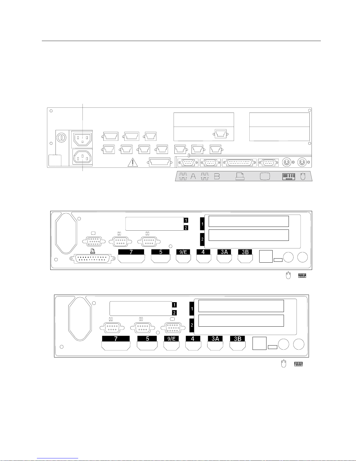
Installing I/O Devices
Note: This section provides information to set up I/O devices most often found on point-of-sale terminals.
The figure below shows typical socket panels at the rear of the system unit. The panels differ slightly,
depending on the model of your terminal. Refer to Table 1-1 on page 1-4 when plugging your cables.
VideoAC PowerOutlet
34
Power
Connector
ACin
5A 5B 9C
3A 3B 4A 4B 9A 9B 11
7
38V
Typical 4693
PCMCIASlots
A
B
4694 Model 041, 044 or 144
12
SerialBSerialA
Parallel Video Auxiliary
Keyboard
1234
Power
Connector
A
Chapter 1. Installing Input/Output Devices 1-3
PCMCIASLOTS
B
1234
4694 Model 001, 004 or 024
Page 16

Table 1-1. Plug Locations for I/O Devices
Type of Device Box No. Cable No. System Unit
Socket
Cash Drawer 3 3 3A or 3B 1
40-Character Vacuum Fluorescent Display
40-Character VFD II,
40-Character Liquid Crystal Display,
Character/Graphics Display,
Shopper Display
Flat Panel Display LCD 4 and LCD
Video Display
4 4 4, 4A, 4B, 9A, 9B 1
4 and
Created February 23, 1997
Notes
2
Keyboard 5 5
Printer 7 7 7
Scanner or Hand-held Bar Code Reader 9, 9C, or 9/E 1
4693 Model 202 (satellite terminal) 11 11
RS232C Device
Parallel Printer
Mouse
Option Adapters 2
Notes: :
1. Plug the cables according to your Store Planner’s instructions.
2. Your terminal may have one or more option adapters installed at the time of manufacture. Follow your Store
Planner’s instructions for connecting any cables to these adapters.
5, 5A, 5B, or
or
, option adapter
slots 1 or 2
1
1
1-4 Installation and Operation for POS I/O Devices
Page 17
Created February 23, 1997
Installing the Cash Drawer and the System Unit
1 Place the cash drawer in the desired
location.
2 Place the system unit on top of the cash
drawer, if the unit is integrated.
3 Open the rear cover on the cash drawer and
remove it.
4 Connect the cash drawer cable to the 3A or
3B socket on the rear panel of the system
unit.
5 Connect the other end of the cable to the
rear of the cash draw (socket 3).
6 Connect the AC power cord to the system
unit.
Do not plug the other end of power cord
to an outlet yet.
7 Route the power cord down toward the
bottom of the cash drawer.
8 Install the cash drawer rear cover.
Note: Other models may vary.
9 The cash drawer is installed. Install any
other I/O devices at this time, otherwise go
to “Installing the System Unit Rear Cover” on
page 1-21.
3
Cover
Release
Button
(Both Sides)
Pin
Hole
Rear Cover
PowerCord
Chapter 1. Installing Input/Output Devices 1-5
Page 18
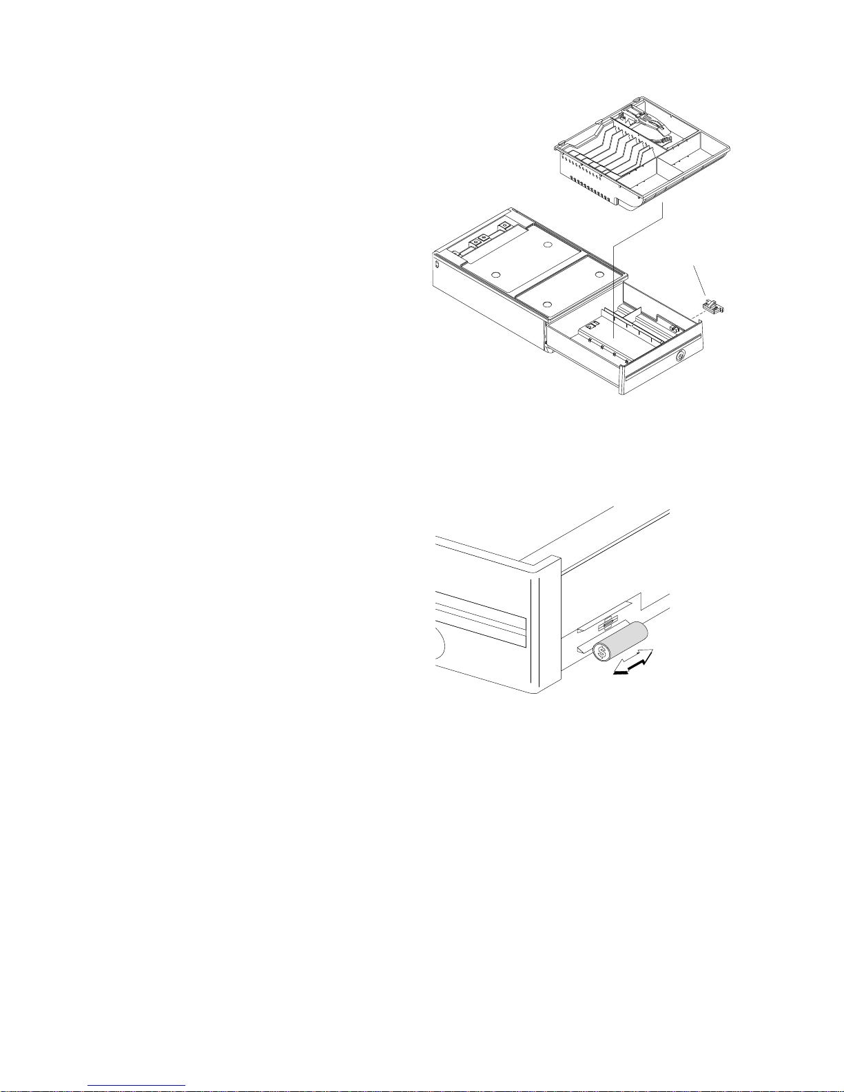
Installing the Compact Cash
Drawer Coin Roll Cutter
1 Open the cash drawer and pull it all the way
out.
2 Remove the till.
3 From inside the drawer, squeeze the cutter
latches together with your fingers and push
the cutter outward until it can be removed
from the outside.
4 To exchange the cutter, snap the new one
into position from the outside.
5Reassemble.
Created February 23, 1997
Coin Roll Opener
Using the Compact Cash Drawer
Coin Roll Cutter
1. Either push or pull the roll against the coin roll
cutter until a score is made in the outside
cover.
2. Then break roll open with your hands.
1-6 Installation and Operation for POS I/O Devices
Page 19

Created February 23, 1997
Installing the 9-Inch Video
Display
1 Hold the display and its base over the
system unit and route the two cables through
the opening at the rear of the base.
Tab
2 Ensure that two tabs at bottom rear of the
display base fit into slots in top of system
unit.
3 Place the display base over the three screw
holes in top of the system unit and tighten
the screws.
Note: The display should be mounted on
the left side when used with the Model 3R or
4R printer.
4 The display is installed. Install any other I/O
devices at this time, otherwise go to
“Installing the System Unit Rear Cover” on
page 1-21.
Installing an Integrated Keyboard
Note: If your keyboard cable has a round plug
on one end, it may be easier to first connect the
round plug to the system unit and then route the
cable up through the opening of the system unit
that is inline with the keyboard socket. If the plug
is not round, follow these instructions.
Slot
Slots
1 Connect cable 5 to the keyboard.
2 Route the keyboard cable straight back and
through the nearest opening at the rear of
the system unit.
3 Place the keyboard so the slots in the front
of keyboard engage with tabs at the front
edge of system unit.
4 Be sure the side of the keyboard overlaps
the tabs on the side of the system unit.
5 Be sure the carder reader opening is aligned
with the slot in the system unit.
6 The keyboard is installed. Install any other
I/O devices at this time, otherwise go to
“Installing the System Unit Rear Cover” on
page 1-21.
Chapter 1. Installing Input/Output Devices 1-7
Tabs
Card
Reader
Openings
Page 20

Installing the Fillers
Notes:
1. On an integrated unit, pull out on the locking
lever at the left side of system unit.
2. Ensure that the side of each filler overlaps the
tab on the side of the system unit.
1 If you have a video display on an integrated
terminal:
Created February 23, 1997
a Move the display on its arm to the side
and remove any tape holding the
alignment ring.
b Remove knockout section of display
filler.
c Align the display filler with the
alignment ring and slide the filler onto
the ring. Press the display filler into
place.
2 If you do not have a video display:
a Place the display filler on the system
unit. DO NOT REMOVE the knockout
section.
3 If you have a short keyboard:
a Place the keyboard filler beside the
keyboard. The fillers are installed.
Install any other I/O devices at this
time, otherwise go to “Installing the
System Unit Rear Cover” on
page 1-21.
Display
Filler
Knockout
Section
Alignment
Ring
DisplayFiller
Keyboard
Filler
1-8 Installation and Operation for POS I/O Devices
Page 21

Created February 23, 1997
Installing the Keyboard Filler Panel:
The keyboard filler panel is available on the
following models with a Sure Point Touch Screen:
4693, 4694 Models 041, 044, and on the Cash
Drawer I/O Integration Kit.
1 Place the filler so the slots in the front of
filler engage with tabs at the front edge of
system unit.
2 Make sure the side of the filler overlaps the
tabs on the side of the system unit.
3 Press in on the locking levers at the left side
of the integration kit so that its lugs engage
the filler. Check to be sure the locking lever
securely holds the filler to the integration kit.
Locking
Level
Tabs
Slots
Installing the Printer
1 Remove any packing material from inside or
under the printer.
2 Connect cable 7 at the bottom of the printer.
Route the cable through the center opening
and place the printer on the system unit.
3 Be sure the side of the printer overlaps the
tab on the side of system unit. On an
integrated unit pull out on the locking lever at
the left side of system unit. The printer is
installed. Install any other I/O devices at this
time, otherwise go to “Installing the System
Unit Rear Cover” on page 1-21.
Chapter 1. Installing Input/Output Devices 1-9
Page 22

Securing I/O Devices to the
System Unit
1 Press in on the locking lever at left side of
system unit so that its lugs engage the
keyboard, printer, and fillers.
2 Check to be sure that the locking lever
securely holds the I/O devices and fillers to
the system unit.
Installing the Alphanumeric
Display
Created February 23, 1997
Locking Lever
1 Plug display cable 4 to the display and route
it through the yoke and post as shown. The
end of the cable that has the round core
connects to the display.
2 Spread the arms of the yoke open slightly
and slide the display into the yoke.
3 Route the cable through opening in the
system unit at base of display.
4 Attach the display post to the system unit,
using two plastic thumbscrews. The notch in
the base of the post faces the rear.
5 The display is installed. Install any other I/O
devices at this time, otherwise go to
“Installing the System Unit Rear Cover” on
page 1-21.
Core
Yoke
Front
Post
1-10 Installation and Operation for POS I/O Devices
Page 23

Created February 23, 1997
Installing the 40-Character Liquid Crystal Display
1 Slide the display up into its holder until it
latches securely in place.
2 Route display cable 4 up through the post.
The end of the cable that has the round core
connects to the display.
3 Plug the cable into the display unit.
4 Hold the display holder against the post as
shown so the interlocking surfaces contact
each other.
5 Rotate the display holder toward you to its
final position. Make sure the display is
securely attached to the post.
6 Snap the round top cover onto the post.
7 Route the cable through opening in the
system unit at the base of display.
8 Attach the display post to the system unit,
using two plastic thumbscrews. The notch in
the base of the post faces the rear.
9 The display is installed. Install any other I/O
devices at this time, otherwise go to
“Installing the System Unit Rear Cover” on
page 1-21.
Notes:
a. Two displays can be stacked on a single
post. The displays can face toward the
front or the rear.
b. The optional ‘Y’ cable is required when
connecting two LCD displays to a 4694.
Chapter 1. Installing Input/Output Devices 1-11
Page 24

Install 40-Character Vacuum Fluorescent Display II
Note: The yoke for a two-sided display is taller
than the yoke for a single-sided display. The
installation procedure is the same for both.
1 Plug display cable 4 into the display. The
end of the cable that has the round core
connects to the display.
2 Spread the arms of the yoke open slightly
and slide the display into the yoke.
3 Route the cable through opening in the
system unit at the base of display.
4 Attach the display post to the system unit,
using two plastic thumbscrews. The notch in
the base of the post faces the rear.
Created February 23, 1997
Display
Yoke
5 The display is installed. Install any other I/O
devices at this time, otherwise go to
“Installing the System Unit Rear Cover” on
page 1-21.
Installing the Character Graphics
Display
1 Press the release buttons at bottom of
display to open the rear cover.
2 Display cable 4 has a black core near one
end. Plug that end into the correct socket
on the system unit. See Table 1-1 on
page 1-4 for plug locations.
3 Route the cable up through the opening in
the system unit and up through the display
post.
4 Plug the cable into the display.
5 Attach the display post to the system unit,
using two plastic thumbscrews. The notch in
the base of the post faces the rear.
Release Buttons
Notch
Core
6 Snap the rear cover closed.
7 The display is installed. Install any other I/O
devices at this time, otherwise go to
“Installing the System Unit Rear Cover” on
page 1-21.
1-12 Installation and Operation for POS I/O Devices
Page 25

Created February 23, 1997
Installing the Shopper Display
1 Route the cable through the post or arm.
2 Firmly press the display into the post or arm
until it snaps into place.
3 If the display is mounted on an arm, press
the cable into two notches on the underside
of the arm.
4 Route the cable through the opening in
system unit at the base of the display.
5 Attach the display post or arm to the system
unit, using two plastic thumbscrews.
Note: The notch in the base of post faces
the rear.
6 The display is installed. Install any other I/O
devices at this time, otherwise go to
“Installing the System Unit Rear Cover” on
page 1-21.
Post or Arm
Chapter 1. Installing Input/Output Devices 1-13
Page 26
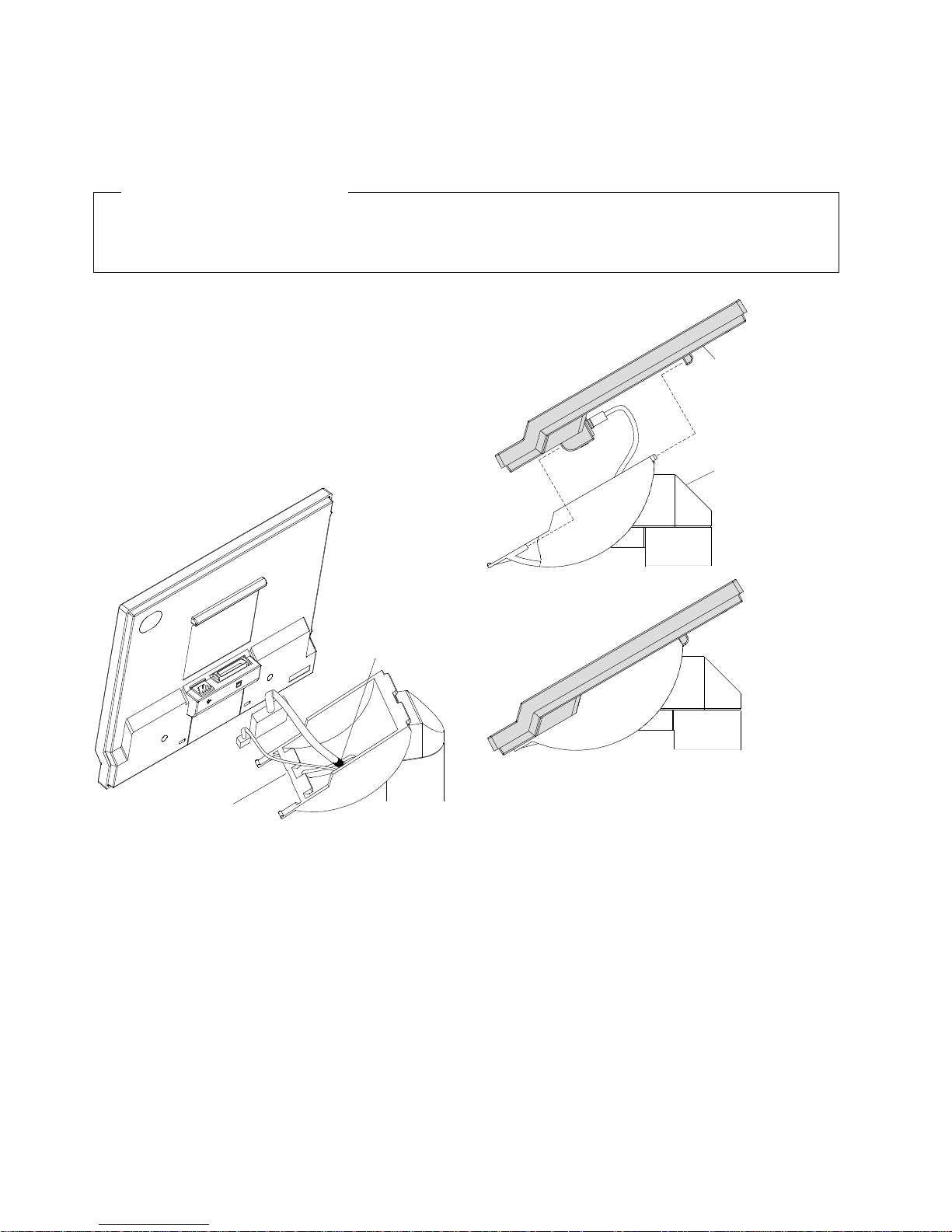
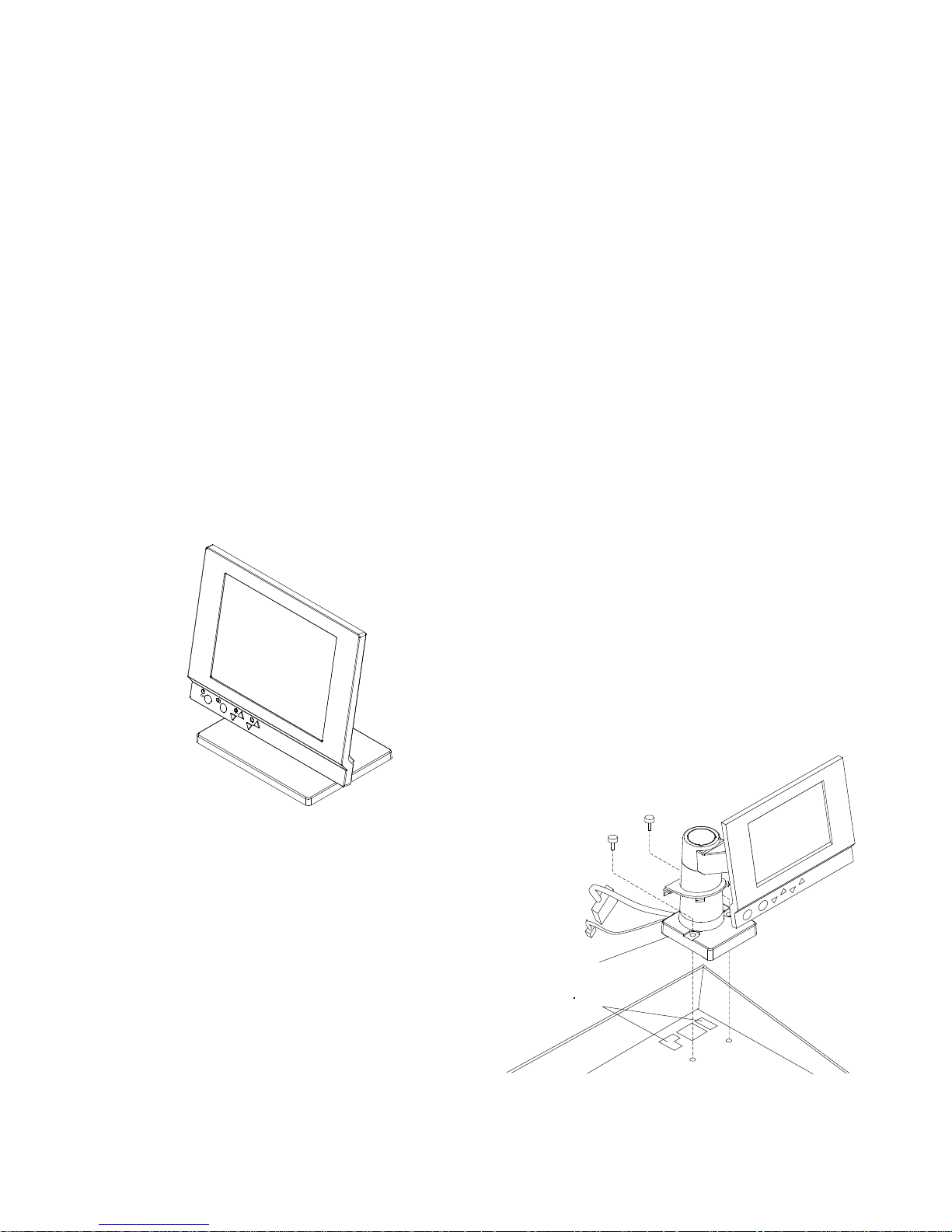
Installing a Flat Panel or Sure Point Touch Display
This section explains the installation of the flat panel or touch display and its accessory kits.
Before Installing the Display
The adapter for this display (if required), should be installed before setting up the display. See the
IBM Store System Adapters: Installation and Service
1 Connect the two cables to the connectors on
the rear of the touch display.
, GA27-4009.
Created February 23, 1997
2 Attach the display to the display holder. See
Figure 1-2.
3 Continue to page 1-15 and choose either the
integration or distribution installation
instructions.
Cable
Position
Mark
Display
Holder
Tilted Up
Display
Display
Holder
Figure 1-3. Installing the Display Unit
Figure 1-2. Display Holder Tilted Up
1-14 Installation and Operation for POS I/O Devices
Page 27
Created February 23, 1997
Installing the Distribution Kit
1 Place the distribution kit on the checkstand.
2 If required, install an M5 screw (not
provided) to the bottom to secure the
distribution kit to the checkstand.
Note: If it is necessary for the operator to
change the tilt and rotate positions of the
display, the distribution kit must be secured
to the checkstand.
3 Plug the large cable into the socket of the
adapter card or system unit LCD socket.
4 Plug the small cable into socket 4, 4A, 4B,
9A, or 9B.
5 Refer to testing information in the reference
documentation for your system and run the
Touch Display Test.
Installing the Integration Kit
1 Ask your Store Planner to determine whether
the integration kit should be installed on the
left or right side of the system unit or cash
drawer.
2 Hold the integration kit over the system unit
and route the two cables through the
opening at the rear. Be sure the cables are
completely pulled through the opening.
3 Place the integration kit over the two screw
holes of the system unit or cash drawer.
There are alignment slots to ensure proper
positioning of the integration kit.
4 Tighten two thumbscrews on the base to
secure the integration kit to the system unit.
5 Plug the large cable into the socket of the
adapter card or system unit LCD socket.
6 Plug the small cable into socket 4, 4A, 4B,
9A, or 9B.
Figure 1-4. Distribution Kit with Display Attached
7 To install the filler panel and rear panel, see
the
IBM Store Systems: Installation and
Operation Guide for Point-of-Sale
Input/Output Devices
, GA27-4028.
8 Refer to testing information in the reference
documentation for your system and run the
Touch Display Test.
Tabs
Alignment
Slots
Chapter 1. Installing Input/Output Devices 1-15
Figure 1-5. Integration Kit with Display Attached
Page 28

Installing the Optional MSR Kit on the Sure Point Touch Display
1 Remove the tab on the back of the touch display.
2 Plug in the MSR cable.
3 Align the MSR into position.
4 Slide it into the attached position.
5 Reinstall the MSR tab.
Created February 23, 1997
1 2
4
3
5
1-16 Installation and Operation for POS I/O Devices
Page 29
Created February 23, 1997
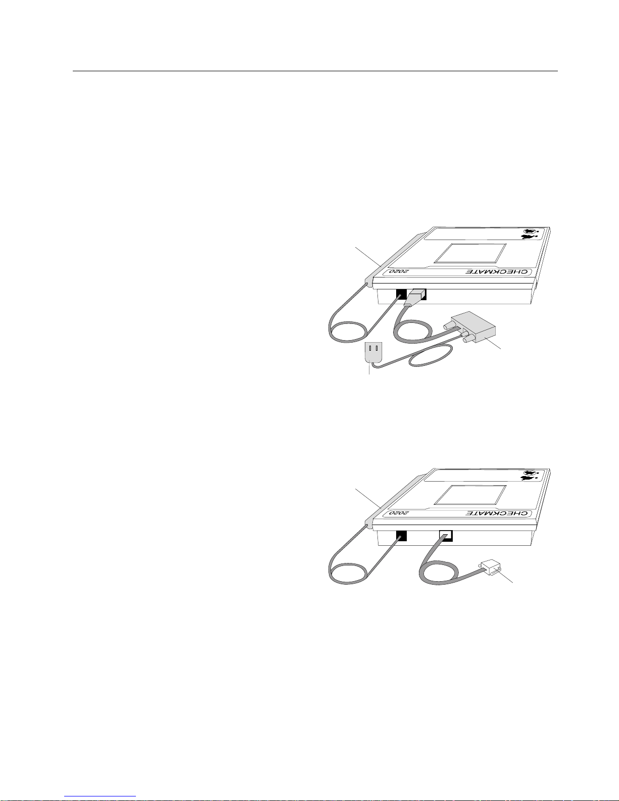
Installing the Signature Capture Device
There are two different models of the signature capture device that attach to an IBM 4683, 4684, 4693, or
a 4694 Point of Sale Terminal:
¹ Checkmate** 2020 Model A01 consists of an electromagnetic tablet, pen, and RS485 interface cable.
¹ Checkmate 2020 Model A02 consists of an electromagnetic tablet, pen, and RS232 interface cable
and AC adapter.
Note: The pen refill is a supply item that is exchanged by the user.
Installing the RS232 Interface
Model
1 Connect the pen cable to the rear four-pin
modular socket.
2 Connect the RS232 interface cable to the
remaining rear socket. Connect the other
end of the cable to an available RS232 port
on the point-of-sale terminal.
3 Connect the AC adapter cable to the RS232
connector.
Pen
RS232
Interface
Cable
AC Adapter
4 Plug the AC adapter in the upright position
into an AC electrical outlet.
Installing the RS485 Interface
Model
1 Connect the pen cable to the rear four-pin
modular socket.
2 Connect the RS485 cable to the remaining
rear socket.
3 Connect the other end of the cable to an
available port on the rear panel of the
point-of-sale terminal: 4B, 9A, 9B, 9C, or
9/E.
Figure 1-6. Signature Capture Device RS232 Interface
Model
Pen
RS485
Interface
Cable
Figure 1-7. Signature Capture Device RS485 Interface
Model
Chapter 1. Installing Input/Output Devices 1-17
Page 30
Created February 23, 1997
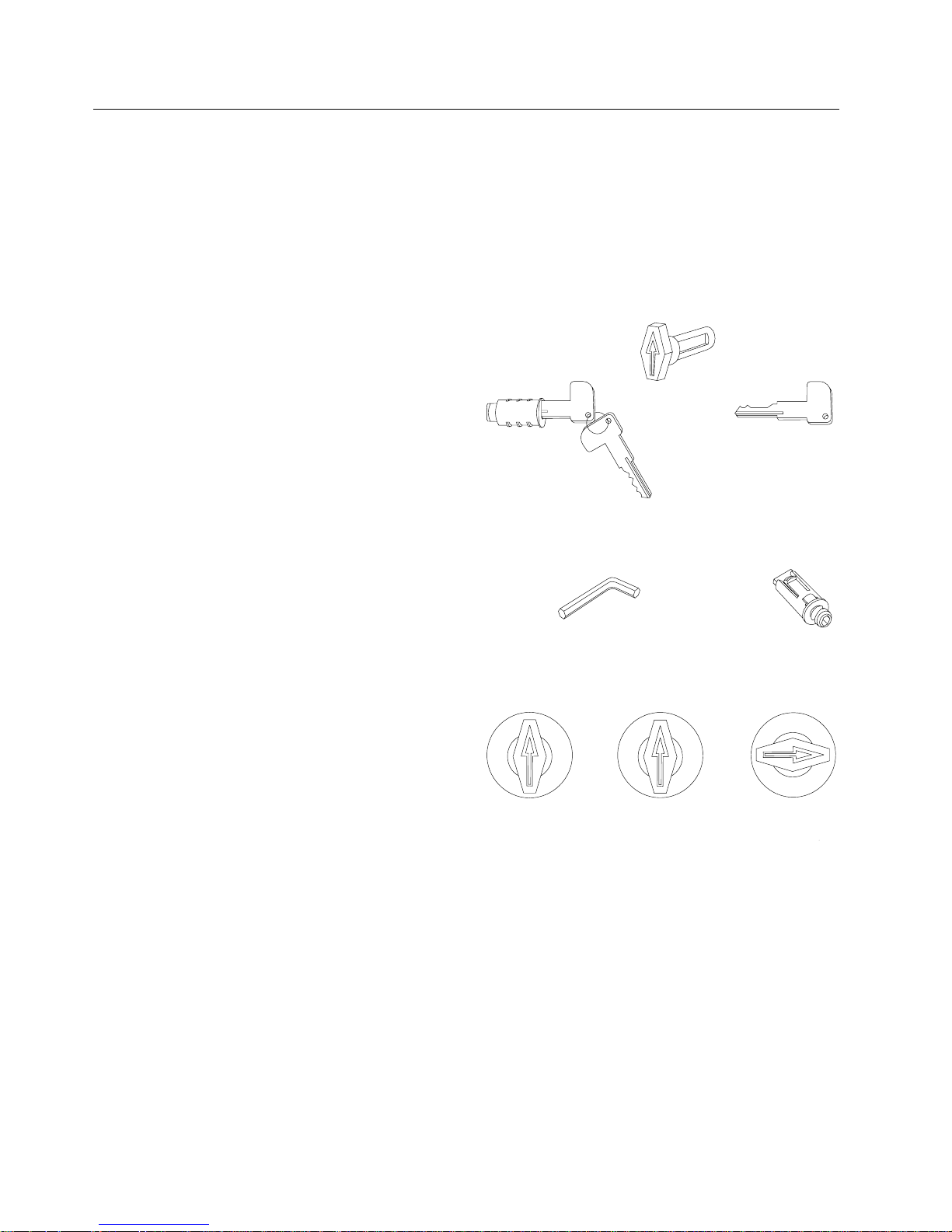
Installing and Removing Keylocks
The system unit, cash drawer, keyboard, and printer can have optional keylocks that prevent unauthorized
persons from using the terminal. If no lock is installed, a blank lock insert can be used to cover the
opening made for the lock.
Preparing to Install a Lock or a Blank Lock Insert
To install a lock insert, you need the following
items:
Aligner
Lock insert and keys
Brass installation/removal key
LockInsertand Keys
Aligner
BrassInstallation/
RemovalKey
To install a blank lock insert, you need the
following items:
Blank lock installation handle
Blank lock insert
The aligner is a tool used to ensure that the slot at
the bottom of the lock cylinder aligns with the lock
insert being installed.
The figure shows the aligner in place in the lock
cylinder of different devices. Note that when the
aligner is in place, the arrow points in different
directions, depending on the kind of device. Refer
to this figure for reference when you install a lock
in the different devices.
InstallationHandle
Keyboard
BlankLock
CashDrawer
Blank
LockInsert
Printer
1-18 Installation and Operation for POS I/O Devices
Page 31
Created February 23, 1997
Installing a Lock Insert
The example shows how to install a lock insert in
a cash drawer. However, the procedure is the
same for installing a lock in any device. To check
that the slot at the bottom of the lock cylinder
aligns with the end of the lock insert:
1 Put the aligner into the empty lock cylinder.
2 Gently turn the aligner until you feel it go into
the slot at the bottom of the lock cylinder.
3 Turn the aligner so that the arrow points in
the proper direction for this device.
4 Remove the aligner.
Note: Some cash drawers may have a different
style lock. If the lock for your cash drawer is
different than the one described here, refer to the
instructions that came with the lock.
Be sure each lock and its keys have matching
numbers. To install the lock insert:
1 Remove the keys from the lock insert.
2 Push the brass installation/removal key fully
into the lock insert.
3 Hold the lock and brass key so that the key
points in the same direction as did the
aligner.
4 Push the lock insert and brass key fully into
the empty lock cylinder.
5 Hold the lock insert in place with your finger
and remove the brass key.
The lock insert is now installed.
6 Test the lock to be sure it operates correctly
with the keys.
7 Return the brass installation/removal key, the
aligner, and blank lock installation handle to
your supervisor for safekeeping.
Chapter 1. Installing Input/Output Devices 1-19
Page 32

Removing a Lock Insert
To remove a lock insert:
1 Put the brass installation/removal key into
the lock until you hear it click into place.
2 Gently pull the brass key.
The brass key and the lock insert should
come out of the lock cylinder together.
Pressing down on the brass key as you pull
makes it easier for the lock insert to come
out along with the brass key.
Installing a Blank Lock Insert
Blank lock inserts are used to cover the opening
at the lock cylinder if no lock has been installed.
Created February 23, 1997
1 Hold the blank lock insert so that the lug is
aligned with the slot in the lock cylinder.
2 Push the blank lock insert into the empty
lock cylinder until it is flush with the top of
the lock cylinder.
3 Use the blank lock installation handle to turn
the locking screw clockwise until it reaches
the bottom of the hole. Do not overtighten.
The blank lock insert is now installed.
4 Return the brass installation/removal key,
aligner, and blank lock installation handle to
your supervisor for safekeeping.
Removing a Blank Lock Insert
To remove a blank lock insert:
Use the blank lock installation handle to turn
the locking screw counterclockwise until you
can lift the blank lock insert out of the lock
cylinder.
1-20 Installation and Operation for POS I/O Devices
Page 33

Created February 23, 1997
Installing the System Unit Rear
Cover
1 Hold the system unit rear cover in position
as shown.
2 Choose one end of the rear cover, insert the
pin on the cover into the hole in the system
unit.
3 At the other end of the cover, press the
flexible strip holding the pin to permit the
cover to snap into place.
4 Arrange the cables neatly and close the rear
cover.
Note: See “Installing and Removing Keylocks” on
page 1-18 to install any locks or blank lock inserts
that go in your I/O devices.
You have completed installation of the I/O
devices. Save any publications or diskettes that
came in the OPEN FIRST box.
Hole
Pin
If you have not yet configured the terminal, refer
to one of the following guides:
IBM 4693 Point of Sale Terminal: Installation
¹
and Operation Guide
¹
IBM 4694 Point of Sale Terminal: Installation
and Operation Guide
¹
IBM 4695 Point of Sale Terminals: Installation
and Operation Guide
, SA27-3978
, SA27-4005
, GA27-4031.
Chapter 1. Installing Input/Output Devices 1-21
Page 34

Created February 23, 1997
1-22 Installation and Operation for POS I/O Devices
Page 35

Created February 23, 1997
Chapter 2. Operating Point-of-Sale I/O Devices
This chapter describes and illustrates the input and output devices on point-of-sale terminals and tells how
to operate them. For illustration purposes, we show the devices on an IBM 4693 Point of Sale Terminal.
Displays . . . . . . . . . . . . . . . . . . . . . . . . . . . . . . . . . . . . . . . . . . . . . . . . . . . . . . 2-2
Adjusting the Controls on Video Displays ................................. 2-3
Cash Drawers . . . . . . . . . . . . . . . . . . . . . . . . . . . . . . . . . . . . . . . . . . . . . . . . . . . 2-4
Keylock Positions . . . . . . . . . . . . . . . . . . . . . . . . . . . . . . . . . . . . . . . . . . . . . . . 2-5
Document Storage Area Under Cash Till ................................. 2-5
Keyboards . . . . . . . . . . . . . . . . . . . . . . . . . . . . . . . . . . . . . . . . . . . . . . . . . . . . . 2-5
Function Keys . . . . . . . . . . . . . . . . . . . . . . . . . . . . . . . . . . . . . . . . . . . . . . . . . 2-6
Enhanced Alphanumeric Keyboard ................................... 2-6
Manager’s Keylock . . . . . . . . . . . . . . . . . . . . . . . . . . . . . . . . . . . . . . . . . . . . . . 2-6
Keyboard Lights (Status Indicators) ..................................... 2-7
Printers . . . . . . . . . . . . . . . . . . . . . . . . . . . . . . . . . . . . . . . . . . . . . . . . . . . . . . 2-7
Operating the Model 2 Point of Sale Printer ................................. 2-8
Opening/Closing the Document Insert Station ............................... 2-8
Inserting Documents in the Model 2 Printer ................................ 2-9
Inserting a Document at the Front .................................... 2-9
Inserting a Document at the Side .................................... 2-9
Advancing the Journal Paper on the Model 2 Printer .......................... 2-10
Advancing the Customer Receipt ..................................... 2-10
Tearing the Customer Receipt ....................................... 2-10
Unlocking the Journal Cover ........................................ 2-10
Testing the Model 2 Printer ........................................ 2-11
Operating the Model 3 or 4 Point of Sale Printer .............................. 2-11
Inserting Documents in the Model 3 or 4 Printer ............................ 2-11
Inserting a Document at the Front ................................... 2-12
Inserting a Document at the Top .................................... 2-12
Aligning the Print Line on an Inserted Document ............................ 2-13
Advancing the Customer Receipt Paper or Journal Paper ....................... 2-13
Unlocking the Journal Cover ........................................ 2-13
Testing the Model 3 or 4 Printer ..................................... 2-14
Model 4A Point of Sale Printer ........................................ 2-15
Model 3R and Model 4R Point of Sale Printers .............................. 2-15
Operating the Model 3R and Model 4R Printer ............................. 2-16
MICR Read Head Cleaning ....................................... 2-16
Installing the Ribbon Cartridge ..................................... 2-16
Inserting MICR Checks in the Printer ................................. 2-16
Running the Stand-Alone MICR Test ................................. 2-16
Special MICR Characters ........................................ 2-18
Entering Data at Your Terminal ........................................ 2-18
Operating Card Readers and Bar Code Readers ............................ 2-18
Cleaning the Card Reader ......................................... 2-19
Entering Data with the Hand-Held Bar Code Readers ......................... 2-19
Operating the Signature Capture Device .................................. 2-20
Signature Submission . . . . . . . . . . . . . . . . . . . . . . . . . . . . . . . . . . . . . . . . . . . . 2-20
Replacing the Pen Refill – Version 1 ................................... 2-20
Replacing the Pen Refill – Version 2 ................................... 2-20
Copyright IBM Corp. 1994, 1995 2-1
Page 36

Created February 23, 1997
Displays
The 40-character vacuum fluorescent display,
40-character liquid crystal display, and the
character/graphics each displays two lines of 20
characters each. The 40-character display can be
used in graphic mode.
Alphanumeric Display
Character/Graphics Display
The terminal can have a 9 inch monitor; either
monochrome or color. The monitor can be
integrated with the terminal or distributed in a
desired location.
The flat panel display has 640(H) x 480(V) dots.
Distributed 9-Inch
Color Display
Distributed 9-Inch
Monochrome Display
40 Character Vacuum
Fluorescent
Display II (single sided)
Liquid Crystal Display
Vacuum Fluorescent
40 Character
Display II (Two sided)
Flat Panel Display
Monochrome and Color
Sure Point Touch Screen
The Sure Point Touch Screens are 9.5 inch liquid
crystal displays with a touch screen panel. They
can be setup in an integrated arrangement or they
can be placed by themselves in a distributed
arrangement.
2-2 Installation and Operation for POS I/O Devices
Page 37

Created February 23, 1997
The shopper display can display one row of eight
characters, with commas and decimal points. It
also has six indicator lights to further provide
information to the customer.
Shopper Display
on Post
Shopper Display
on Arm
Adjusting the Controls on Video
Displays
There are two versions of the 9-inch monochrome
display. One version has an ON/OFF switch and
has brightness and contrast controls. See
Figure 2-1. The other version has an ON/OFF
switch and has brightness contrast, vertical size,
and horizontal center controls. See Figure 2-2.
Video controls
are located under
the front edge.
Vertical
Size
Horizontal
Center
Contrast
Brightness
Off/On
Switch
Figure 2-2. Controls on 9-Inch Monochrome Display
The 9-inch color display has an ON/OFF switch
and has five video controls for adjusting the
screen.
Video controls
are located under
the front edge.
Horizontal
Center
Vertical
Size
Vertical
Center
Brightness
Contrast
Off/On
Switch
Figure 2-3. Controls on 9-Inch Color Display
Figure 2-1. Controls on 9-Inch Monochrome Display
Chapter 2. Operating Point-of-Sale I/O Devices 2-3
Page 38

Created February 23, 1997
Cash Drawers
There are three kinds of cash drawers. All three
cash drawers can have removable cash tills and
till covers with locks. Two cash drawers are
similar in size to the system unit and opens
toward the front. One fits wide system units and
one fits small systems. They can serve as the
base for the terminal in an integrated arrangement
or placed by themselves in a distributed
arrangement. An optional keylock permits them to
open under an application program control or by
means of a key.
The compact drawer, is smaller in size. It can
serve as the base for the terminal in an integrated
arrangement or it can be placed by itself in a
distributed arrangement. An optional keylock
permits it to open under application program
control or by means of a key.
Cash Drawer
The flip-top cash drawer, is smaller in size. It can
be used in distributed arrangements where space
may be limited. Its top cover hinges up. It, too,
can have an optional keylock to permit the top
cover to open under application program control or
by means of a key.
Flip-top
Cash Drawer
2-4 Installation and Operation for POS I/O Devices
Page 39
Created February 23, 1997
Keylock Positions
The cash drawer keylock has three positions:
¹ Locked closed
¹ Operate
¹ Manual open/locked open
The Operate position permits the cash drawer to
open under application program control. The key
is normally turned to this position while the
terminal is in operation. The key can be removed
while in any of the three positions.
Document Storage Area Under
Cash Till
Space is available under the cash till for storing
documents. Use the slot at the front of the cash
drawer for depositing documents. An adjustment
bar inside lets you adjust the size of the document
storage area to suit your needs.
LockedClosed Operate ManualOpen/LockedOpen
Depth
Adjustment
Bar
Keyboards
Several kinds of keyboards are available with a variety of features. Most have a built-in magnetic card
reader.
RetailPointofSaleKeyboard
RetailPointofSaleKeyboard
withCardReader
RetailPointofSaleKeyboard
withCardReaderandDisplay
EnhancedAlphanumericKeyboard
RetailAlphanumericPointofSale
Keyboard withCardReader
Chapter 2. Operating Point-of-Sale I/O Devices 2-5
ModifiableLayoutKeyboard
withCardReader
Page 40

Function Keys
Function keys, such as S1 and S2, permit the
terminal to perform certain functions or operations
with few keystrokes by the operator.
On keyboards that have a Ctrl (Control) key, the
S1 and S2 functions require a combination of two
keys:
1 Press and hold the Ctrl key.
2 Then, press the S1 or S2 key.
If no Ctrl key is present, you need only to press
the S1 or S2 key. Figure 2-4 illustrates the keys
on a typical keyboard.
S2
S1
CtrlKey
Figure 2-4. Example of S1 and S2 Function Keys
Created February 23, 1997
Enhanced Alphanumeric Keyboard:
On the enhanced alphanumeric keyboard:
The ESC (Escape) key functions as S1.
The ENTER key functions as S2.
Manager’s Keylock
The keyboards can be equipped with a manager’s
keylock, for special override functions as
determined by your store procedures.
During normal operations, the keylock is in the
OFF position. When needed, it can be turned to
the ON position to enable special keying functions,
and then turned OFF again. The key cannot be
removed while it is in the ON position.
Enter(S2)
ESC(S1)
Figure 2-5. Example of Function Keys on Enhanced
Alphanumeric Keyboard
Manager's
Keylock
Figure 2-6. Manager’s Keylock
2-6 Installation and Operation for POS I/O Devices
Page 41
Created February 23, 1997
Keyboard Lights (Status Indicators)
Four lights, or status indicators, on the keyboard
provide information about the system. Three of
the lights are labeled: Wait, Offline, and Message
Pending. The fourth light is not labeled.
The lights operate under application program
control. The following table describes the typical
use of these lights. Refer to your store operating
procedures for specific information on how these
lights work.
Light Meaning
Wait The application program
running on the terminal is
waiting for an action to
complete (for example, waiting
for a program to load).
Offline Normal online operations have
been interrupted and you can
display an offline message
using system function keys. An
offline message gives you
information related to the offline
condition.
Message
Pending
Unlabeled Reserved
A system message is waiting to
be displayed on the terminal,
and can be displayed using
system function keys.
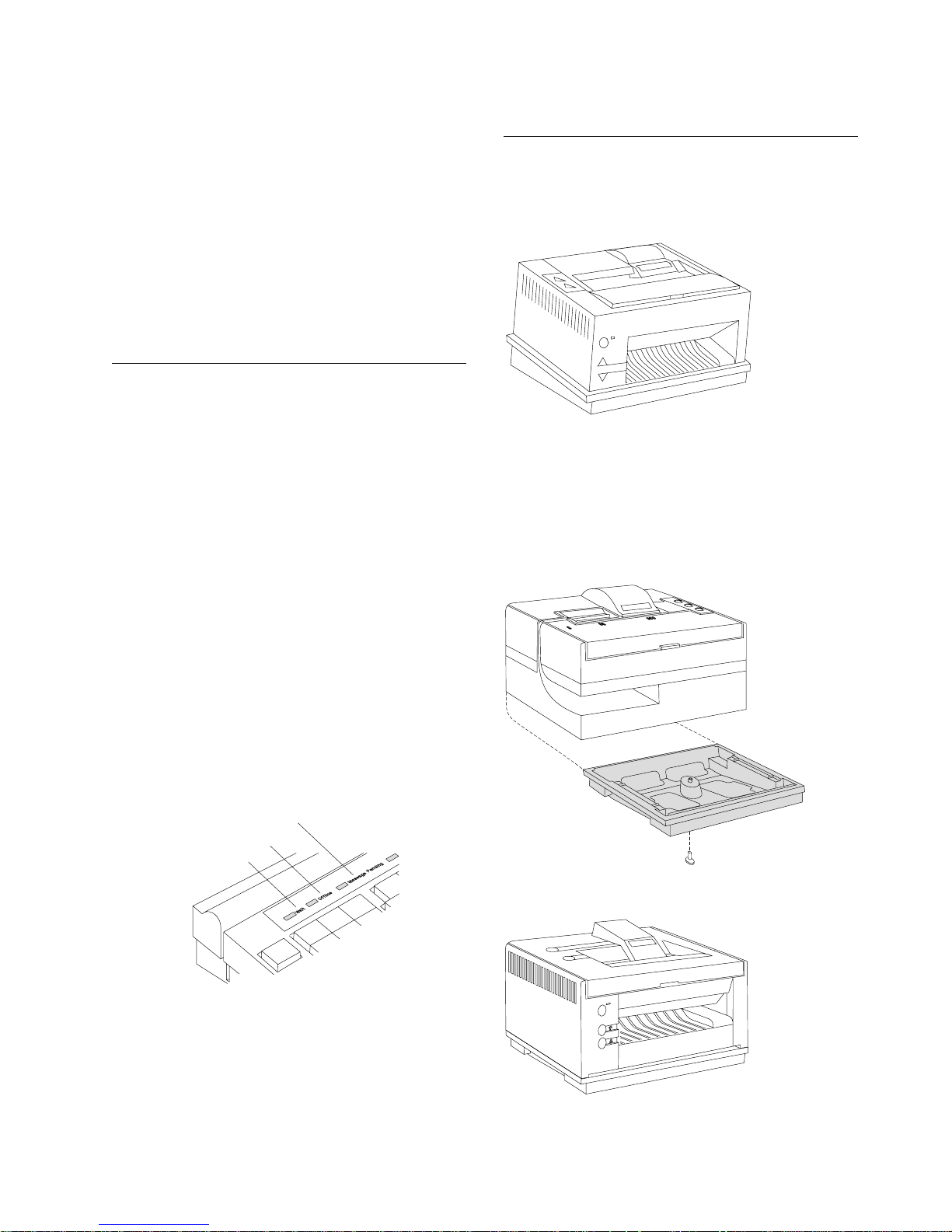
Printers
The Model 4 Printer is designed for a 4693
system unit that has a slanted fence on top.
Figure 2-8. Point-of-Sale Printer Model 4
A base is available for the Model 2 and 3 printers,
that allows them to be placed on an I/O integration
kit. The base holds the printer in a slanted
position, in the same manner in which a Model 4
printer is held.
Message Pending
Offline
Wait
Figure 2-7. Keyboard Status Lights
Chapter 2. Operating Point-of-Sale I/O Devices 2-7
Figure 2-9. Point-of-Sale Printer Model 2
Figure 2-10. Point-of-Sale Printer Model 3
Page 42

Operating the Model 2 Point of Sale Printer
Note: Consult your store procedures for information on the correct method of operating the document
insert station.
The Model 2 printer has four buttons located on
the top of the printer. These buttons are used to:
Created February 23, 1997
III Advance paper at the journal station
II Advance paper at the customer receipt
station
I Open and close the document insert
station
T Test the printer
Three of the buttons are visible when the printer
cover is closed. The test button is visible only
when the printer cover is raised.
Opening/Closing the Document
Insert Station
The document insert station can be opened or
closed under application program control or it can
be operated manually using the document insert
button.
JournalAdvanceButton
Customer ReceiptAdvanceButton
Document InsertButton
TestButton
Figure 2-11. Buttons on a Model 2 Printer
The document insert station is normally open and
ready for insertion of a document.
1 Insert the document. (The following sections
describe how to insert documents.)
2 Press the I button to manually close the
station.
Note: Pressing the I button is not
necessary if your printer has been
programmed to close the document insert
station automatically.
2-8 Installation and Operation for POS I/O Devices
Page 43
Created February 23, 1997
Inserting Documents in the Model 2 Printer
Note: Consult your store procedures for information on the correct method of operating the document
insert station.
When you want to print on a check or form, insert the document into the document insert station. You can
insert the document at either the front or the side. Consult your store procedures or authorized personnel
at your store for information on inserting documents. You can insert documents that are fastened
together, provided they are not fastened together on the right side.
Note: Do not insert a document with staples, metal inserts, or holes in the area to be printed.
Inserting a Document at the Front
1 Insert the document with the side to be
printed facing up.
2 Push the document against the right wall of
the insert station and forward until it comes
to a stop.
Inserting a Document at the Side
Your store procedures or a message on your
terminal display may tell you which documents
should be inserted at the side. Use the raised
mark on the left side of the printer to help you line
up documents.
1 Insert the document, sliding it to the right as
far as it can go.
2 Be sure to line up your document correctly;
the first line of printing begins where the
mark is located.
3 Press the document insert button marked I
to manually close the station after the
document is lined up correctly. Pressing the
I button is not necessary if the printer has
been programmed to close automatically.
If the document needs to be adjusted after
you have closed the document insert station,
press the document insert button marked I
and adjust the document. Press the button
marked I again to close the document insert
station.
Right Wall
Figure 2-12. Inserting a Document at the Front of
Model 2 Printer
Raised
Mark
Chapter 2. Operating Point-of-Sale I/O Devices 2-9
Figure 2-13. Inserting a Document at the Side of
Model 2 Printer
Page 44

Created February 23, 1997
Advancing the Journal Paper on
the Model 2 Printer
To advance the journal paper:
1 Press the III button.
2 The journal roll advances one line each time
you press the button, or it continues to
advance if you press and hold the button.
Advancing the Customer Receipt
To advance the customer receipt:
1 Press the II button.
2 The customer receipt advances one line
each time you press the button, or it
continues to advance if you press and hold
the button.
Note: If you have a document inserted in the
document insert station, pressing the II button
advances the document. Be sure to remove all
documents from the document insert station
before pressing the II button to advance the
customer receipt.
Unlocking the Journal Cover
Your terminal may have an optional keylock for
securing the journal cover. This keylock is located
under the printer cover near the printer buttons.
To unlock the journal cover:
1 Raise the printer cover.
2 Insert the journal cover key into the journal
keylock and turn it to the unlocked position.
3 Open the journal cover.
4 To lock the journal cover, reverse these
steps. Be sure to remove the journal cover
key. The printer cover does not close until
the key is removed.
Locked
Unlocked
Tearing the Customer Receipt
To tear off the customer receipt, pull the paper
toward the front of the printer (not toward the
sides) and tear it against the tear bar.
2-10 Installation and Operation for POS I/O Devices
Page 45

Created February 23, 1997
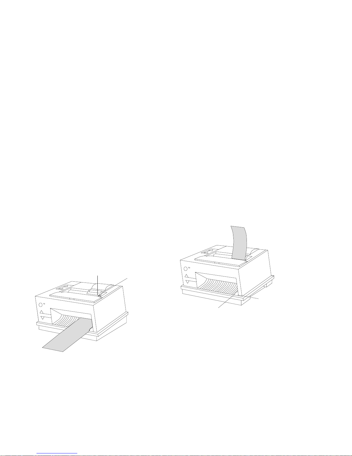
Testing the Model 2 Printer
The printer test button is located under the printer
cover and can only be used when the cover is
open. This button runs a test that lets you know
that the print head is seated properly and the
printer is working correctly. Use this button each
time you install the paper, ribbon cartridge, or print
head.
CAUTION:
For safety when running the printer test, make
sure personal articles such as ties, necklaces,
or bracelets do not get caught in the moving
print head.
To run the printer test:
1 Raise the printer cover.
2 Press the T button.
Operating the Model 3 or 4 Point
of Sale Printer
Note: Consult your store procedures or
authorized personnel at your store for information
on inserting documents.
Model 3 and 4 printers have two buttons located
on the top and three on the front. These buttons
are used to:
Advance journal station paper
Advance customer receipt station paper
Advance an inserted document a preset
number of lines (Ready)
Advance an inserted document
Withdraw an inserted document
Run tests on the printer
The buttons on a Model 3 printer differ slightly in
appearance, but their function remains the same.
T
Figure 2-14. Test Button on Model 2 Printer
3 A test begins that prints two lines of 38
characters in both stations. A quick visual
scan verifies that the printer is printing
correctly.
IHIHIHIHIHIHIHIHIHIHIHIHIHIHIHIHIHIH
IHIHIHIHIHIHIHIHIHIHIHIHIHIHIHIHIHIH
Button
AdvanceJournalButton
CustomerReceiptAdvanceButton
ReadyButton
DocumentInsert Upbutton
DocumentInsert Downbutton
Figure 2-16. Buttons on Model 4 Printer
Inserting Documents in the Model
3 or 4 Printer
When you want to print on a check or form, insert
the document into the printer at the front or at the
top.
Figure 2-15. Printer Test Pattern
4 Tear off the customer receipt paper before
closing the cover.
Chapter 2. Operating Point-of-Sale I/O Devices 2-11
Page 46
Created February 23, 1997
Inserting a Document at the Front
To insert a document at the front:
1 With the side to be printed facing up, insert
the document into the front of the document
insert station until it stops.
Note: The form must be inserted into the
document insert station with enough force so
that it moves between the rollers.
2 When the green light next to the Ready
button goes ON:
¹ Consult your store procedures or
authorized personnel at your store for
information on completing the document
insert transaction.
¹ Press the Ready button to move the
document a preset number of lines into
the printer.
¹ Press the document insert button Up
button to move the document into the
printer one line at a time.
Inserting a Document at the Top
1 With the side to be printed facing you, insert
the document into the top of the document
insert station until it stops.
2 When the green light next to the Ready
button goes ON:
¹ Consult your store procedures or
authorized personnel at your store for
information on completing the document
insert transaction.
¹ Press the Ready button to move the
document a preset number of lines into
the printer.
¹ Press the document insert button Down
button to move the document into the
printer one line at a time.
Note: If the document is not inserted
correctly, the document insert button Up
button to back it out. Return to Step 1 and
try again.
Note: If the document is not inserted
correctly, press the document insert button
Down button to back it out. Return to Step
1 and try again.
Top Load
Form Guide
Tab
Figure 2-17. Inserting a Document at the Front of
Model 4 Printer
MICR and Wide Load
Load Form Guide
Normal Front Load
Form Guide
Figure 2-18. Inserting a Document at the Top of
Model 4 Printer
2-12 Installation and Operation for POS I/O Devices
Page 47

Created February 23, 1997
Aligning the Print Line on an
Inserted Document
To align an inserted document:
Press the Ready button to move the
document a preset number of lines into the
printer.
- or -
Press the document insert button Up or the
document insert button Down to move the
document into the printer one line at a time.
Advancing the Customer Receipt
Paper or Journal Paper
To advance the customer receipt, press the
customer receipt button. To advance the journal
station, press the journal button. See page 2-11.
The customer receipt advances or the journal
station advances one line each time you press the
button with the cover open or 12 lines each time
you press the button with the cover closed. They
continue to advance if you press and hold the
button with the cover open or closed.
Unlocking the Journal Cover
Your terminal may have an optional keylock for
securing the journal cover. This keylock is located
under the printer cover, to the right of the journal
cover.
To unlock the journal cover:
1 Raise the printer cover.
2 Insert the journal cover key into the journal
keylock (on the right side of the journal
cover).
3 Turn the key to the unlocked position.
4 Open the journal cover.
To lock the journal cover, reverse these
steps. Be sure to remove the journal cover
key. The printer cover does not close until
the key is removed.
Locked
Note: If the document insert station is occupied,
you will be able to advance the customer receipt
paper or journal paper, but the printer does not
print at the customer receipt station.
Unlocked
Chapter 2. Operating Point-of-Sale I/O Devices 2-13
Page 48

Created February 23, 1997
Testing the Model 3 or 4 Printer
The printer test lets you know the printer is
working correctly. It can only be run when the
cover is open and the printer has power.
CAUTION:
For safety when running the printer test, make
sure personal articles such as ties, necklaces,
or bracelets do not get caught in the moving
print head.
To run the printer test on the journal station:
1 Close the printer cover. Then open the
cover to clear any outstanding journal errors.
2 Press and hold the Ready button and then
press the journal advance button.
3 The test begins and prints 50 lines of 38
characters at the journal station.
You can stop the test at any point by
pressing the Ready button.
IHIHIHIHIHIHIHIHIHIHIHIHIHIHIHIHIHIH
IHIHIHIHIHIHIHIHIHIHIHIHIHIHIHIHIHIH
Figure 2-19. Printer Test Pattern
A quick visual scan verifies that the printer is
printing correctly.
You can stop the test at any point by pressing
the Ready button.
To run the printer test on the customer receipt
station:
1 Raise the printer cover.
2 Press and hold the ready button and then
press the customer advance receipt button.
3 The test begins and prints 50 lines of 38
characters at the customer receipt station.
A quick visual scan verifies that the printer is
printing correctly. You can stop the test at
any point by pressing the Ready button. If
necessary, tear off the customer receipt paper
before closing the cover.
Note: Pressing the Ready button while the test is
running stops the test and causes the customer
receipt paper cutter to cut the paper. This verifies
that the cutter is functioning correctly.
To run the printer test on the document
station:
1 Raise the printer cover.
2 Insert a blank document into:
The top of the printer and move it into
the printer by pressing the document
insert button Down button.
- or -
The front of the printer and move it into
the printer by pressing the document
insert button Up button.
3 Press and hold the Ready button and then
press:
The document insert button Up button to
run the test and move the document out
the top of the printer.
- or -
The document insert button Down button
to run the test and move the document
out the front of the printer.
4 The test begins and prints 50 lines of 38 test
pattern characters on the inserted document.
5 Remove the document from the printer by
pressing:
The document insert button Up button to
move the document out the top of the
printer.
- or -
The document insert button Down button
to move the document out the front of
the printer.
A quick visual scan verifies that the printer is
printing correctly. You can stop the test at
any point by pressing the Ready button.
AdvanceJournalButton
CustomerReceiptAdvanceButton
ReadyButton
DocumentInsert Upbutton
DocumentInsert Downbutton
2-14 Installation and Operation for POS I/O Devices
Figure 2-20. Testing the Model 4 Printer
Page 49

Created February 23, 1997
Model 4A Point of Sale Printer
Installing a model 4A Printer
The Model 4A Point of Sale Printer is available on
the IBM 4693 and 4694 Point of Sale Terminal.
This model is similar to the Model 4, but in
addition, contains non-volatile (FLASH) memory.
FLASH memory provides the capability for the
user to download any country-specific character
sets (fonts) into the printer.
the
IBM 4693 Point of Sale Terminals:
Introduction and Planning Guide
, SA27-3977.
Operating the Model 4A Point of Sale Printer
For DOS systems, the FLASH memory loading
procedure is described in the FL.DOC file in the
\FL directory on diskette 2 of the
Subsystem/DOS Drivers
, SX27-3960 and
Point of Sale
SX27-3961, Version 1.20 or later.
There is no unique installation procedure or
planning required for the Model 4A Point of Sale
Printer. Use the
Terminals: Setup Instructions
IBM 4693 Point of Sale
, PN 73G1012 and
For POSS/2 systems, the FLASH memory loading
procedure is described in
Point of Sale
Subsystem/2 Programming Reference and User's
Guide
Version 1.1 (or later), SC30-3560.
Model 3R and Model 4R Point of Sale Printers
Introduction
Model 3R and Model 4R Point of Sale Printers read the magnetic ink characters printed at the bottom of
most checks, while maintaining the functions of the standard Model 3 and Model 4 printers. The Magnetic
Ink Character Recognition (MICR) device consists of a read head, located in the document insert station
and the associated circuitry on the printer extension card and printer logic card. Model 3R and 4R printers
are identified by the presence of a check orientation label at the front of the printer. Figure 2-21 shows
the location of the label on a Model 4R printer.
X
0103
Figure 2-21. Model 4R Printer With Check Orientation Label
Installing and Planning
Model 3R and 4R printers are designed to read
Model 3R and 4R printers automatically position checks for franking at the completion of a MICR read
operation. Franking is limited to a maximum of 20 characters per line at 15 characters per inch. If more
characters per line are required the check must be reinserted at the normal document stop.
Video Display Placement
Terminals should be configured with the video display to the left of the printer. If a video display is
installed too close to the right side of the Model 3R or 4R printer, check reading failures may occur. If
you experience this problem, move the display away from the printer as far as practical. A spacing of
25 mm or more should be maintained between a video display and the side of the Model 3R or Model
4R printer.
Chapter 2. Operating Point-of-Sale I/O Devices 2-15
E13B
and
CMC7
MICR character fonts.
Page 50

Created February 23, 1997
Operating the Model 3R and Model 4R Printer
MICR Read Head Cleaning: A cleaning kit consisting of 10 individually wrapped cleaners is
available using order number 73G2600. Cleaning instructions are printed on each package.
Installing the Ribbon Cartridge: When installing or replacing the ribbon cartridge on a Model 3R
or 4R printer, make sure that the ribbon does not get caught behind the MICR pressure pad.
To help prevent this, install the ribbon cartridge in the printer before placing the ribbon holder onto the
print head.
Inserting MICR Checks in the Printer: Checks are automatically positioned for franking at the
end of a MICR read operation. Do not insert a check with staples, paper clips, or other items that may
hinder the check movement.
¹ With the check face down and the bottom of the check against the right side frame (not the normal
document stop), push the check inward until it is stopped. The green light next to the Ready button
comes ON.
Notes:
1. Model 3R and 4R printers cannot read punched card checks.
2. Model 3R and 4R printers cannot read checks that have data printed in the last 33 mm of the
character line (amount field).
3. Consult the store procedures or authorized personnel at your store for information on completing
the check reading operation.
X
0103
Figure 2-22. Inserting a Check in the MICR Printer
Figure 2-23. Check Orientation Label on Printer
Running the Stand-Alone MICR Test: When the printer access cover is open, the Ready button
functions as a test button. The other four buttons, when pressed individually, function as paper advance
buttons. See Figure 2-24 on page 2-17.
Note: Order P/N 73G2601 for a package of 10 checks.
2-16 Installation and Operation for POS I/O Devices
Page 51

Created February 23, 1997
ReadyButton
Hold for
3seconds.
MICRCharacters
Figure 2-24. Printer Buttons
CAUTION:
For your safety when running this test, make
sure personal articles such as ties, necklaces,
or bracelets do not get caught in the moving
print head.
MICR Check Reading Failure
Magnetic interference from a nearby video
display, transformer, power supply, or other
electrical device can cause MICR check
reading failures. If you experience this
problem, try moving any suspected electrical
devices away from the printer as far as
practical.
¹ The paper is installed correctly in the
customer receipt print station. For
installation instructions, see the
reference documentation for your
system.
3 With the check face down and against the
right side frame, push the check inward until
it stops. The green Ready LED comes ON.
4 Press and hold the green Ready button for
three seconds to initiate the MICR test.
Note: If you continue to hold the Ready
button, the test repeats every three seconds.
The check is fed into the printer until it gets
to the top. The checkfeed is reversed and
the MICR characters are read while feeding
out the front. The MICR characters read are
then printed at the customer receipt station.
When the test detects failures on the first
read operation, it automatically feeds and
reads the check a second time. After the
check is read a second time, the characters
that were read are printed, regardless of any
read errors.
5 Compare the characters at the bottom of the
check with those that are printed. The
numeric characters should be the same.
See Table 2-1 on page 2-18 for special
characters.
1 Open the cover on the printer.
2 Ensure the following conditions are met:
¹ The printer is attached to the POS
terminal.
¹ The power is ON at the POS terminal.
¹ There is no document inserted in the
document insert station.
¹ The test does not detect the presence of
a check (Green Ready LED does not
come ON).
¹ No characters are printed after the check
is read.
¹ The printed characters are different than
those printed on the check.
¹ Two passes of the check are required to
read the characters.
¹ The checks jam.
6 The stand-alone MICR test is complete.
Chapter 2. Operating Point-of-Sale I/O Devices 2-17
Page 52

Created February 23, 1997
Special MICR Characters: Some of the
special MICR characters at the bottom of a check
cannot be printed. Table 2-1 illustrates the
characters that print when these special
characters are read.
Table 2-1. Printing Special MICR
Characters
Special
Character
Printed
Character
$
A
T
- (dash)
Table 2-2. CMC7 Special
Characters
Special
Character
Printed
Character
a
b
c
d
Entering Data at Your Terminal
The following sections show how to enter sales
transaction data at your terminal using the card
reader and bar code readers and scanners.
Operating Card Readers and Bar
Code Readers
The card reader is also referred to as a magnetic
stripe reader (MSR). To enter data:
1 Hold the magnetic stripe card horizontally
with the stripe at the bottom and facing you.
2 Place the card in the card reader.
3 With a steady, smooth motion, pass the card
through the reader. You can pass the card
through the reader in either direction; from
the left or from the right.
The response you receive is controlled by the
application program for your store. If the data was
not accepted, check to see if you positioned the
card correctly. If you did not, turn the card to the
correct position and pass the card through the
reader again with a steady, smooth motion.
e
Figure 2-25. Reading a Magnetic Stripe Card
2-18 Installation and Operation for POS I/O Devices
Page 53

Created February 23, 1997
Cleaning the Card Reader
If you are using the card reader correctly and get
a large number of misreads, you may need to
clean the read head with an MSR cleaning card.
The cleaning card, Part Number 6019483, is
available through your IBM Marketing
Representative. The card reader should be
cleaned about every 10,000 passes. To clean the
card reader:
1 Locate the special cleaning card.
2 Hold the card horizontally with the stripe at
the bottom and facing you.
3 Pass the card through the reader several
times in either direction, using a smooth,
steady motion.
Entering Data with the Hand-Held
Bar Code Readers
To read the barcode label on an item, do the
following:
1 Holding the item in one hand, put the bar
code reader steadily over the bar code label
so that it is square with the label.
move the bar code reader from side to side
2 Gently touch the reader to the label.
If you have used the bar code reader correctly,
some action takes place at your terminal,
depending on your application. For example, a
“beep” may sound, the display may change, or the
printer may start printing.
If the reading was not successful:
1 Check to see that the bar code label is not
blocked by debris or damaged.
2 Make sure the bar code label is
perpendicular to the reader, and not angled
sideways. The bars on the label should be
in a vertical position for successful reading.
Do not
.
Figure 2-26. Hand-Held Bar Code Reader
Chapter 2. Operating Point-of-Sale I/O Devices 2-19
Page 54

Operating the Signature Capture Device
This section describes how to operate the signature capture device.
Signature Submission
1 The Sales Associate should slide the
document under the document guide.
Checkmate
Created February 23, 1997
620
2 Start the signature when the green SIGN
light comes on.
Note: The length of time the SIGN light is
on can be varied (10–100 seconds),
dependent on the application program. The
default is set at 20 seconds.
Replacing the Pen Refill –
Version 1
1 Unscrew the nose cone.
2 Pull out the old pen refill.
3 Install the new pen refill, ensuring it is firmly
inserted into the pen until the end bottoms
out on the refill holder.
4 Screw the nose cone back onto the end of
the pen.
Replacing the Pen Refill –
Version 2
Sign
Light
Do Not
Sign Light
Versions 1
Refill
Cone
Version 2
1 Unscrew the two halves of the pen.
2 Pull out the pen refill. Install the new pen
refill, ensuring it is firmly inserted into the
pen until the end bottoms out on the refill
holder.
3 Screw the pen halves back together.
Note: Use a Cross** pen refill or the
equivalent.
2-20 Installation and Operation for POS I/O Devices
Page 55

Created February 23, 1997
Appendix A. Expendable Supplies and Replaceable Parts
This appendix describes expendable supplies and replaceable parts for your terminal and identifies how to
order them.
How to Order Expendable Supplies
In the U.S.A, order expendable supplies from IBM Direct. In IBM World Trade countries, order from IBM
Direct, if it is available in your country. If IBM Direct is not available in your country, order through your
IBM Marketing Representative or your dealer.
Table A-1. Expendable Supplies
Item IBM Part Number
Ribbon cartridges for Point-of-Sale Printer Model 2 4483015 (black ink)
1040247 (purple ink)
Ribbon cartridges for Point-of-Sale Printer Models 3 and 4 1040888 (black ink)
1040875 (purple ink)
1040900 (black Auto-Inking)
Roll paper for IBM point-of-sale printers 432767 (1 case, 50 rolls per case)
Storage retention battery (standard duration)
Storage retention battery (extended duration/4693 only)
Notes:
1. These batteries have a shelf life of two years and should not be
purchased in bulk as spares.
2. These batteries are of nickel-cadmium (Ni Cd) composition.
Due to laws in some countries, they require special disposal
procedures according to local country regulations. Return used
storage retention batteries to IBM for disposal.
3-1/2 inch - 2.0 MB High Density Diskettes 6404078 (Box of 10)
3-1/2 inch - 4.0 MB Diskettes 72X6111 (Box of 10)
MICR cleaning cards for Model 3R and Model 4R Printers 7362600 (Box of 10)
93F1135
93F1785
or
6404083 (Box of 10)
Ribbon Cartridge for Point-of-Sale Printers
A ribbon cartridge, two rolls of paper, and a printer cable are shipped as a kit with IBM Model 2 printers.
A ribbon cartridge and two rolls of paper are shipped as a kit with IBM Model 3 and 4 printers.
Note: Use the IBM printer ribbons listed in Table A-1 or other equivalent ribbons that use dye-based ink.
The use of carbon-particle ribbons or other ribbons that are not equivalent to the IBM ribbons affect print
head life and print quality.
Copyright IBM Corp. 1994, 1995 A-1
Page 56

Created February 23, 1997
Roll Paper for Point-of-Sale Printers
Two rolls of paper are shipped with the printer cable. One for the journal print station and the other for the
document insert customer receipt station. For additional rolls, you can order the IBM part numbers listed
in Table A-1 on page A-1 or equivalent. Both print stations use standard adding machine roll paper. The
roll paper must meet the specifications in the following table:
Table A-2. Specifications for Roll Paper used in Point-of-Sale Printers
Width 69.85 + 0.5 mm – 0.76 mm (2.75 +0.02 in. – 0.03 in.)
The maximum the core may protrude on either side is 0.76 mm (0.030 in.).
Outside diameter 89 mm (3.5 in.) maximum (for Model 2 printers)
81 mm (3.2 in.) maximum (for Model 3 or 4 printers)
Thickness 0.076 ±10% (0.003 ±10%)
Weight 61 grams/m² (16 lb)
Grade Service or high grade (economy or bond)
Attachment The inner end of the roll must be secured by a reverse-tuck-start with a 19 mm (0.75 in.)
maximum fold back.
Splices There must be no splices within the paper roll.
Marking There must be dye stripes on the paper beginning 122 ±15 cm (48 ±6 in.) from the inner
end of the roll and extending to within 30 cm (12 in.) of the end of the roll.
Core Core material and center hole diameter are optional.
Paper must not be attached to the core in any way
.
A-2 Installation and Operation for POS I/O Devices
Page 57

Created February 23, 1997
Additional Forms for Point-of-Sale Printer Model 2
The use of printed forms at the document insert station is optional. The following specifications apply to
forms that may be used at the document insert station:
Table A-3. Specifications for Document Insert Forms used in the Model 2 Printer
Form Type Specifications
Single-part form 216 mm x 330 mm (8.5 in. x 13 in.) is the recommended maximum.
69.9 mm x 152.4 mm (2.75 in. x 6 in.) is the recommended minimum.
69.9 mm x 82.5 mm (2.75 in. x 3.25 in.) is the minimum single-part form that can be used, but
it only allows approximately three (3) lines of printing.
Multi-part form 216 mm x 330 mm (8.5 in. x 13 in.) is the recommended maximum.
82.5 mm x 187.3 mm (3.25 in. x 7.37 in.) is the recommended minimum.
Tab card Size: 82.5 mm x 123.2 mm (3.25 in. x 4.85 in.)
Weight: 57 to 90 grams/m² (15 to 24 lb. paper or tab card stock
Thickness: 0.0762 mm (0.003 in.) paper to 0.2 mm (0.008 in.)
Ledger card stock maximum (uncoated card stock only)
Multi-part Forms for Point-of-Sale Printer Model 2: Multi-part forms may be used in the
document insert station. The maximum form thickness is 0.47 mm (0.0185 in.).
Top fastening is recommended on all forms regardless of size. Fastening is permitted on the left side of
forms that are a minimum of 101.6 mm (4 in.) wide. Fastening on the right side is not permitted.
Fastening must not extend more than 19.05 mm (.75 in.) from the top, bottom, or left edge of a form.
When bottom fastening is used, printing must start at least 63.5 mm (2.5 in.) from the fastening to help
eliminate potential document feeding problems.
Note: No staples or metal inserts may be used on any area of the form that is inserted in the machine.
No holes or openings are allowed on the form or its fastening. Forms with pre-printed lines or boxes
located in areas to be printed can be used. However, the accuracy of printing between lines or in the
boxes depends on the positioning of the document by the operator.
Appendix A. Expendable Supplies and Replaceable Parts A-3
Page 58

Created February 23, 1997
Additional Forms for Point-of-Sale Printer Model 3 or 4
The following specifications apply to forms that may be used for document insertion:
Table A-4. Specifications – Document Insert Forms for Models 3 and 4 Printer
Form Specifications
Single-part form 216 mm x 330 mm (8.5 in. x 13 in.) is the recommended maximum.
82.5 mm x 69.9 mm (3.25 in. x 2.75 in.) is the recommended minimum.
69.9 mm (2.75 in.) is the minimum width for check franking.
Multi-part form 216 mm x 330 mm (8.5 in. x 13 in.) is the recommended maximum.
82.5 mm x 69.9 mm (3.25 in. x 2.75 in.) is the recommended minimum.
Multi-part Forms for Point-of-Sale Printer Model 3 or 4: Multi-part forms may be used in
the document insertion station. The maximum form thickness is 0.47 mm (0.0185 in.) when inserted into
the front of the printer and 0.25 mm (0.010 in.) when inserted into the top of the printer. The front sheet
should not exceed 0.08 mm (0.003 in.) in thickness. If the multi-part form contains card stock, the card
stock must be the last copy and not exceed 0.2 mm (0.008 in.) in thickness. Also, the sheets of a
multi-part form should be the same size; not uneven or stepped.
Form Design
¹ Print on blank areas of the form. If printing is done inside boxes on the form, the boxes should be
three characters high and the margins should be three characters wide to allow for printer tolerances
and operator variances.
¹ Forms should allow for some amount of alignment error.
¹ The form layout should have the loose edge of the form going into the printer first.
– Sometimes the operator bends the binding along the perforation line. Ensure that the forms are
flat.
– Sometimes forms are produced with a defective or marginal binding. The leading edge on the
form causes most of the problems.
¹ Use a top margin of 29 mm or 1.14 in. or larger. This allows the operator to see the form exit the top
cover before printing starts. The operator can open the top cover to stop the printer and clear out the
jam before any printing occurs.
¹ Order the form without holes or openings. For example, tractor feed holes sometimes get dislodged
inside the printer and turn on the DI sensors. Sometimes the sensors cannot sense the form because
it is looking through a hole.
¹ No staples or metal inserts should be used on any area of the forms that are inserted into the machine
and no holes or openings are allowed on the forms or their fastenings.
A-4 Installation and Operation for POS I/O Devices
Page 59

Created February 23, 1997
Appendix B. Operator and Programmer Information
This appendix has helpful techniques both for the operator and for the programmer, when using
point-of-sale printers.
Operator Techniques for the Point-of-Sale Printers
The following techniques should be followed by the operator.
¹ The operator must insert the form so that it is engaged between the feed rollers. The green sensor
light is activated before the form is between the rollers.
¹ The operator reduces the form twist by pushing the entire width of the form into the feed rollers.
¹ Bent, curled, or defective forms cause problems. The leading edge causes most of the problems.
Ensure that the form is flat.
– Crumpled or curled forms should be smoothed out or flattened as much as possible.
– Select forms from the middle of the stack. Forms on the top tend to curl. This method minimizes
form curl problems.
¹ Folded, wadded, crumpled, or damaged checks are difficult to feed through the printer.
1 The best solution is to fill the check out using a pen rather than attempt to use the printer.
2 If for some reason this cannot be done, the operator should flatten the check out as much as
possible before inserting it into the printer. The entire length of the check must be pushed into
the feed rollers to eliminate the form twist that occurs.
3 If the check does not feed out of the printer correctly, lift the printer cover to stop the printer from
tearing the check.
Note: Damaged checks may feed more reliably if they are inserted from the top rather than
from the front. The application program can allow the operator to insert the check from either
direction.
Application Program Techniques for Point-of-Sale Printers
If the printer jams repeatedly, there are techniques that the application programmer can use to ensure that
the printer should not jam:
1 Move the print head into position before prompting the operator to insert the form.
a. On
narrow
130 mm or 2 1/2 in. to 5 1/8 in. wide.
forms, move the print head to the left-most position. A narrow form is between 70 to
b. On
wide
forms or very narrow forms, move the print head to the center position before prompting
the operator to insert the form into the top or into the front of the printer.
Note: The application program should allow the operator to insert the form from the front and
top of the printer. The application can check the direction of insertion by reading the status of
the upper and lower document insert sensors.
2 The application program should check the status of the document insert Ready bit which gets turned
on when the form activates both document insert sensors.
Copyright IBM Corp. 1994, 1995 B-1
Page 60

If the operator has pressed the key and document insert Ready bit is not turned on, prompt the
operator to push the form further into the printer and press the key again.
3 Move the print head onto the form.
Created February 23, 1997
¹ For front-loaded
the form. The cover holds the form flat so the print head can slide freely over the form.
narrow
forms the first print line is located 20 mm or .75 in. from the top edge of
a Feed the form up past the cover.
b Move the print head onto the form.
c Move the form back down to the first line of print.
¹ For front loaded
the form. Move the print head to the center before advancing the form past the cover. Keeping
the print head at the right or left position can deflect a form so that it catches on the cover inside
the printer.
wide
forms the first print line is located 20 mm or .75 in. from the top edge of
4 After printing is completed, eject the form. Prompt the operator to remove the form.
5 Check the document insert sensors to ensure that the operator has removed the form. Continue with
normal receipt and journal printing.
B-2 Installation and Operation for POS I/O Devices
Page 61

Created February 23, 1997
Appendix C. Display Configurations and Controls
This appendix has information on display configurations and controls.
Flat Panel Display Controls
There are controls on the front to change contrast, brightness, and reverse video.
Contrast The right-hand pair of up and down triangle buttons control contrast. The contrast
changes continuously within the allowable range while the buttons are pressed.
Brightness The left-hand pair of up and down triangle buttons control brightness. The brightness
changes continuously while the buttons are pressed.
Reverse Video The right-hand round button switches the display between normal and reverse video.
Sleep/Resume The left-hand round button controls the Sleep and Resume functions. See “Flat Panel
Display Sleep Control” on page C-2.
Sleep/Resume Button
Sleep Indicator
Figure C-1. Visual Controls
Contrast Control
Brightness Control
Reverse Video/Shift Button
Copyright IBM Corp. 1994, 1995 C-1
Page 62

Flat Panel Display Sleep Control
There is an indicator and a button on the front of the display for sleep control. The following table
describes how to control the sleep modes.
Table C-1. Sleep Control
Sleep
Indicator
Sleep/
Resume
Button
Auto
Sleep
Mode
Is ON when the display is in sleep mode. This also indicates the mode while in setup state.
The left round button controls sleep/resume of display.
In this mode, the display sleeps when the selected sleep time has expired. If no screen
change occurs during this time (1 to 15 minutes), the display automatically goes into sleep
mode. The default time selected by Auto Configuration is three minutes.
Note: Application programs that are constantly changing the screen, such as graphic clocks,
never allow the display to automatically sleep.
The display resumes when at least one of the following conditions is met:
1 Display screen is changed by the application program that is running.
Note: When the display is sleeping and a key is pressed, the screen resumes after
processing the keystroke. This may cause a different screen than expected to appear.
Created February 23, 1997
Manual
Sleep
Mode
Switching
between
Auto and
Manual Mode
Changing
Sleep
Type
2 Sleep/Resume button is pushed.
In this mode, the display toggles between sleep and resume by pressing the Sleep/Resume
button. The selected sleep time chosen by using the Reference Disk Setup Menu has no
effect in manual mode.
To switch between auto and manual sleep mode:
1 Push both the Sleep/Resume button and the Reverse Video button for more than three
seconds to enter setup state.
2 In setup state, the indicator blinks. There are two different sequences of indicator blinks
and by observing this sequence, the current sleep mode can be determined.
Auto mode blink sequence is as follows:
01234567
ON
OFF
Manual mode blink sequence is as follows:
01234567
ON
OFF
SECONDS
SECONDS
3 Push the Reverse Video button to change the sleep mode. Observe the blink sequence.
4 Push the Sleep/Resume button to exit setup state.
While in sleep mode the sleep type can be selected from one of the following choices:
Dim Backlight brightness is fixed to the lowest value
Off Backlight is turned off
Blank Backlight is turned off and the screen is blanked
The sleep type is cyclically changed by using the contrast up/down buttons while in setup
state.
C-2 Installation and Operation for POS I/O Devices
Page 63

Created February 23, 1997
Sure Point Touch Display Controls
There are controls on the front of the touch display that change contrast, brightness, and reverse video.
Sleep/Resume The left-hand round button controls the sleep and resume functions.
Reverse Video The right-hand round button switches the display between normal and reverse video.
This function is available on the monochrome model only.
Brightness The left-hand pair of up and down triangle buttons control the brightness. The
brightness changes continuously while the buttons are pressed.
Contrast The right-hand pair of up and down triangle buttons control the contrast. The contrast
changes continuously within the allowable range while the buttons are pressed.
Sure Point Touch Display Beeper Controls
The controls on the front of the touch display change the frequency and loudness of the beeper.
Beeper Control
Frequency The right-hand pair of up and down triangle buttons and the reverse/shift video button
pressed at the same time control the frequency of the beeper. The frequency changes
continuously within the allowable range (1500-3500 Hz) while the buttons are pressed.
Loudness The left-hand pair of up and down triangle buttons and the reverse video/shift button
pressed at the same time control the loudness of beeper.
Contrast Control
Brightness Control
Reverse Video/Shift Button
Sleep/Resume Button
Sleep Indicator
Mercury Disposal
The touch display contains a cold cathode fluorescent lamp (CCFL) that contains mercury. Dispose of
it in accordance with local ordinances or regulations.
Appendix C. Display Configurations and Controls C-3
Page 64

Created February 23, 1997
Touch Display Sleep Control
There is an indicator and a button on the front of the display for sleep control. Table C-2 describes how
to control the sleep modes.
Table C-2. Sleep Control
Sleep
Indicator
Sleep/
Resume
Button
Auto
Sleep
Mode
Is ON when the display is in sleep mode. This also indicates the mode while using setup.
The left round button controls the sleep/resume function of the display.
In this mode, the display enters sleep condition when the time programmed by the backlight
command has passed after the last touch. The time can be programmed in the range of 1 to
65535 seconds, by the SIO command.
The touch display wakes up when the screen is touched, resume button pushed or when the
SIO command is issued.
The display resumes when one or more of the following conditions are met:
1 The screen is touched.
Manual
Sleep
Mode
Switching
between
Auto and
Manual Mode
2 Sleep/Resume button is pushed.
In this mode, the Sleep/Resume does not cause the display to go to sleep.
3 SIO Backlight command is issued.
In this mode, the display toggles between sleep and resume by pressing the Sleep/Resume
button.
The Sleep/Resume button or SIO commands can be used to put the display to sleep.
To switch between auto and manual sleep mode:
1 Push both the Sleep/Resume button and the Reverse Video button for more than three
seconds to enter setup state.
2 In setup state, the indicator blinks. There are two different sequences of indicator blinks
and by observing this sequence, the current sleep mode can be determined.
Auto mode blink sequence is as follows:
01234567
ON
OFF
Manual mode blink sequence is as follows:
01234567
ON
OFF
SECONDS
SECONDS
3 Push the Reverse Video button to change the sleep mode. Observe the blink sequence.
4 Push the Sleep/Resume button to exit setup state.
Changing
Sleep
Type
C-4 Installation and Operation for POS I/O Devices
Dim Backlight brightness is fixed to the lowest value
Off Backlight is turned off
Blank Backlight is turned off and the screen is blanked
The sleep type is cyclically changed by using the contrast up/down buttons while in setup
state.
Page 65

Created February 23, 1997
Sure Point Touch Display
Calibration
1. Press and hold down the Sleep/Resume
button and at the same time switch Ready
mode On.
2. Wait to hear three beeps, then touch the lower
left corner of the screen. See Figure C-2.
3. Wait to hear two beeps, then touch the upper
right corner of the screen.
4. One more beep indicates calibration is
complete.
5. Load the Reference diskette (Micro Channel)
or the Service diskette (ISA bus).
The menu flow to run the Calibration test is
the same for IBM ISA bus and Micro Channel
Point-of-Sale Terminals. The menus are
dynamic and change depending upon the
configuration.
6. Select Test Menu, when the Main Menu is
displayed.
7. Select Run POS Device Tests.
8. Select Run Terminal X (X=terminal being
tested).
The touch display test and calibration test is
displayed, when the touch display is attached.
Figure C-2. Low Resolution Calibration
Appendix C. Display Configurations and Controls C-5
Page 66

Created February 23, 1997
C-6 Installation and Operation for POS I/O Devices
Page 67

Created February 23, 1997
Index
Numerics
40-character liquid crystal display 2-2
40-character vacuum fluorescent displays 2-2
A
adjusting
controls on 9-Inch video displays 2-3
size of document storage area in cash drawer 2-5
advancing paper in printers
model 2 printer 2-10
model 3 or 4 printer 2-13
aligning the print line on an inserted document, model 3
or 4 printer 2-13
attachment kit
B
base, optional, for model 2 or 3 printer 2-7
blank lock inserts, installing and removing 1-20
buttons
on model 2 printer 2-8
on model 3 or 4 printer 2-11
C
cable plugging chart 1-3
card reader, magnetic
cleaning 2-19
entering data with 2-18
cash drawer
adjusting size of document storage area 2-5
descriptions of 2-4
flip-top 2-4
installing 1-5
keylock positions 2-5
removable cash tills 2-4
special lock insert on some cash drawers 1-19
storing documents in 2-5
character/graphics display 2-2
chart for plugging cables to system unit 1-3
checks, inserting in MICR printer 2-16
cleaning card, for magnetic card reader 2-19
color display, 9 inch 2-2
compact cash drawer
coin roll cutter 1-6
using, coin roll cutter 1-6
controls on 9-inch video displays 2-3
customer setup of devices 1-2
D
displays, description of
40-character liquid crystal 2-2
40-character vacuum fluorescent 2-2
9 inch video 2-2
adjusting controls on 9-Inch video 2-3
character/graphics 2-2
flat panel 2-2
shopper 2-3
document storage in cash drawer 2-5
E
entering data with
hand-held bar code reader 2-19
magnetic card reader 2-18
expendable supplies A-1
F
FCC information vii
fillers, installing 1-8
flash memory in model 4A printer 2-15
flat panel display 1-14
flip-top cash drawer, illustration of 2-4
forms specifications
franking checks 2-15
function keys on keyboards 2-6
I
illustrations
cash drawers 2-4
displays 2-2
keyboards 2-5
point-of-sale printers 2-7
using the magnetic card reader 2-18
indicators, status lights on keyboards 2-7
inserting checks in MICR printer 2-16
inserting documents
for storage under cash till 2-5
model 2 printer 2-9
model 3 or 4 printer 2-11, 2-12
installing
40-character 1-11
40-character VFD II 1-12
4693 terminal I/O devices 1-2
9-inch video display 1-7
alphanumeric display 1-10
cable plugging chart for 4693 terminal 1-3
cash drawer and system unit 1-5
character graphics display 1-12
Copyright IBM Corp. 1994, 1995 X-1
Page 68

Created February 23, 1997
installing
installing a model 4A printer 2-15
installing the model 3R 2-15
(continued)
fillers 1-8
flat panel display 1-14
keyboard 1-7
locks and blank locks 1-18
printer 1-9
securing I/O devices to system unit 1-10
shopper display 1-13
K
keyboard
function keys 2-6
illustrations of 2-5
installing 1-7
manager’s keylock 2-6
status indicator lights on 2-7
keylock
cash drawer 2-5
installing and removing 1-18
manager’s 2-6
model 2 printer 2-10
model 3 or 4 printer 2-13
special lock insert on some cash drawers 1-19
L
lights on keyboard 2-7
liquid crystal display 2-2
locks
install lock insert 1-19
installing and removing blank lock inserts 1-20
preparing to install 1-18
removing a lock insert 1-20
special lock insert on some cash drawers 1-19
M
magnetic card reader
cleaning 2-19
entering data with 2-18
manager’s keylock 2-6
memory, FLASH, in model 4A printer 2-15
MICR printer 2-15
monochrome display, 9 inch 2-2
multipart forms
for model 2 printer A-3
for model 3 or 4 printer A-4
N
non-volatile (FLASH) memory in model 4A printer 2-15
notices
general v
safety ii, vi
O
opening/closing document insert station, model 2
printer 2-8
operate
flat panel display sleep control C-2
flat panel display visual control C-1
inserting MICR checks in printer 2-16
operating a model 4A printer 2-15
optional base for model 2 or 3 printer 2-7
ordering supplies A-1
P
paper
additional forms for model 2 A-3
additional forms for model 3 or 4 A-4
multi-part forms for model 2 A-3
multi-part forms for model 3 or 4 A-4
part number of paper rolls A-1
roll paper specifications A-2
plugging chart for 4693 terminal 1-3
printer test, stand-alone MICR printer 2-16
printer, installing 1-9
printer, model 2
additional forms for A-3
advancing customer receipt paper 2-10
advancing journal paper 2-10
buttons on 2-8
inserting documents 2-9
keylock at the journal station 2-10
multi-part forms for A-3
opening/closing document insert station 2-8
operate 2-8
optional base 2-7
ribbon cartridge part number A-1
roll paper for A-2
tearing the customer receipt paper 2-10
testing 2-11
unlocking the journal cover 2-10
printer, model 3 or 4
additional forms for A-4
advancing customer receipt paper 2-13
aligning print line on an inserted document 2-13
buttons on 2-11
inserting documents 2-11
keylock at the journal station 2-13
multi-part forms for A-4
operate 2-11
ribbon cartridge part number A-1
roll paper for A-2
testing 2-14
unlocking the journal cover 2-13
printers, illustration of 2-7
publications, related viii
X-2 Installation and Operation for POS I/O Devices
Page 69

Created February 23, 1997
R
related diskettes viii
related publications viii
removing and replacing
ribbon, printer
part numbers A-1
roll paper
part number A-1
specifications A-2
S
safety information ii, vi
shopper display 2-3
signature capture device 1-17, 2-20
signature submission 2-20
specifications
roll paper for printers A-2
stand-alone MICR printer test 2-16
status indicator lights on keyboards 2-7
summary of changes ix
supplies
additional forms for printers A-3, A-4
diskettes A-1
how to order A-1
printer ribbons A-1
ribbon cartridges A-1
roll paper A-1, A-2
Sure Point Touch Screen
beeper controls C-3
calibration procedure C-5
color touch display controls C-3
distribution kit 1-15
integration kit 1-15
monochrome touch display controls C-3
optional MSR kit 1-16
touch display 1-14
touch sleep control C-4
T
tearing customer receipt, model 2 printer 2-10
test pattern, example of 2-11
testing
model 2 printer 2-11
model 3 and 4 printers 2-14
till, cash 2-5
touch display 1-14
Index X-3
Page 70

Page 71

Tell Us What You Think!
Store Systems:
Installation and Operation Guide for
Point-of-Sale Input/Output Devices
Publication No. GA27-4028-01
We hope you find this publication useful, readable, and technically accurate, but only you can tell us!
Your comments and suggestions will help us improve our technical publications. Please take a few
minutes to let us know what you think by completing this form. If you are in the U.S.A., you can mail this
form postage free or fax it to us at 1-800-253-3520. Elsewhere, your local IBM branch office or
representative will forward your comments or you may mail them directly to us.
Overall, how satisfied are you with the information in this book? Satisfied Dissatisfied
ØØ
How satisfied are you that the information in this book is: Satisfied Dissatisfied
Accurate ØØ
Complete ØØ
Easy to find ØØ
Easy to understand ØØ
Well organized ØØ
Applicable to your task ØØ
Specific comments or problems:
Please tell us how we can improve this book:
Thank you for your comments. If you would like a reply, provide the necessary information below.
Name Address
Company or Organization
Phone No.
Page 72

Tell Us What You Think!
GA27-4028-01
Fold and Tape Please do not staple Fold and Tape
ÉÂÔ
NO POSTAGE
NECESSARY
IF MAILED IN THE
UNITED STATES
Cut or Fold
Along Line
BUSINESS REPLY MAIL
FIRST-CLASS MAIL PERMIT NO. 40 ARMONK, NEW YORK
POSTAGE WILL BE PAID BY ADDRESSEE
Design & Information Development
Dept. CJMA/Bldg. 645
International Business Machines Corporation
PO BOX 12195
RESEARCH TRIANGLE PARK NC 27709-9990
Fold and Tape Please do not staple Fold and Tape
GA27-4028-01
Cut or Fold
Along Line
Page 73

Page 74

ÉÂÔÙ
Part Number: 42H0486
Created February 23, 1997
Printed in USA
GA27-4028-01
42H0486
 Loading...