

Page 1
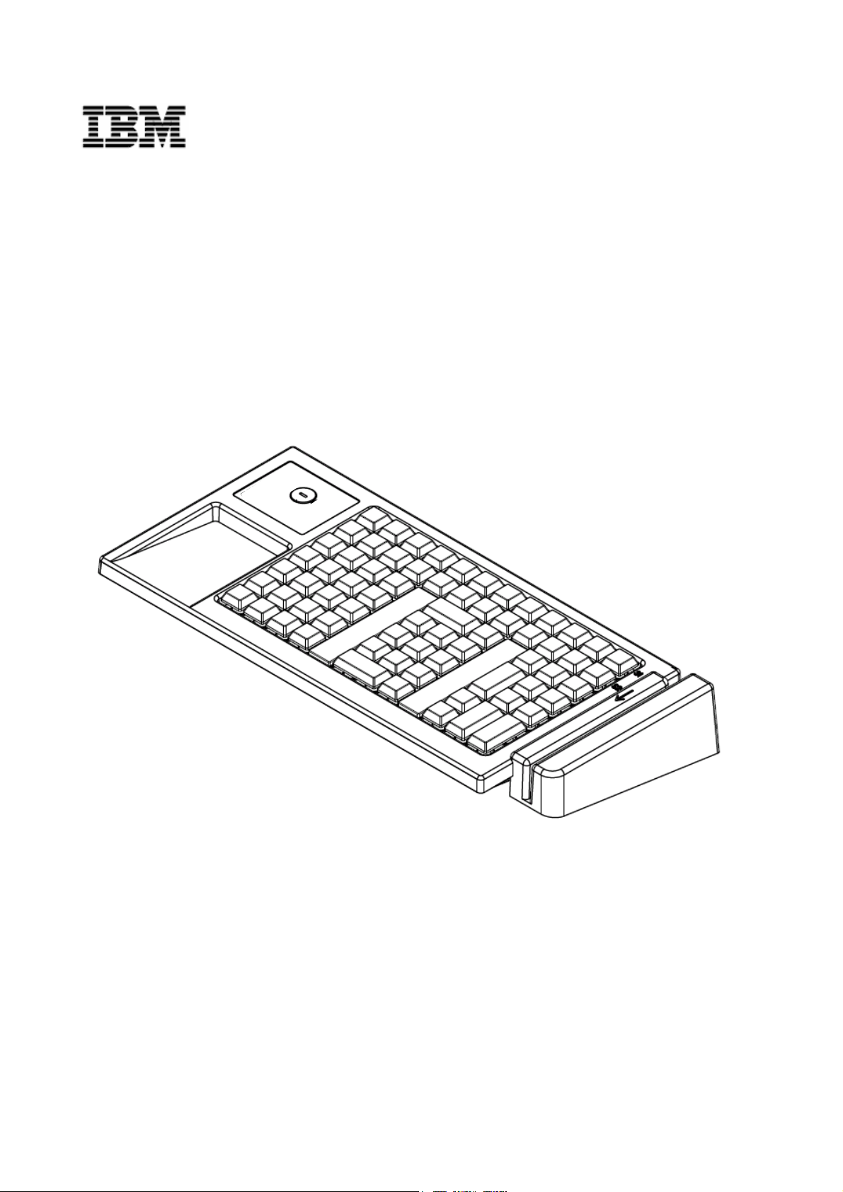
IBM 4685-K03 POS Keyboard
Installation, Operation, and Maintenance Guide
P/N 29R0777
Page 2

IBM is a trademark of the IBM Corporation in the United States or other countries.
First Edition (May 2006)
This manual is revised in accordance with product improvements or for other reasons.
© Copyright International Business Machines Corporation 2006. All rights reserved.
Page 3

Introduction
This manual provides an overview, installation instructions, operating guidelines,
instructions on how to replace the keys, and general maintenance information for the
IBM™ 4685-K03 POS Keyboard.
In this manual, the IBM 4685-K03 POS Keyboard may be referred to as the 4685-K03 or
as the keyboard. The IBM 4800 POS terminal may be referred to as the POS terminal or
as the terminal.
This manual is organized as follows:
Chapter 1, “An overview of the IBM 4685-K03 POS Keyboard” provides an overview
z
of this product and gives the names of the parts.
z Chapter 2, “Installing the keyboard” provides information about installing the
keyboard in the IBM 4800 POS terminal.
z Chapter 3, “Operating the keyboard” provides information about operating
procedures for the keyboard and the functions of each part.
z Chapter 4, “Replacing the keys” provides information about exchange procedures
for the keys and for the unused key covers.
z Chapter 5, “Maintenance of the keyboard” provides information about
problem-solving strategies and part replacement procedures. This section is for
service personnel who specialize in maintaining the POS terminal.
_________________________________________________________________________________________
Who should use this guide
This manual is to be used by service personnel who install the IBM 4685-K03 POS
Keyboard and by customers. Information for service engineers who specialize in the POS
terminal is included in Chapter 5, “Maintenance of the keyboard”.
_________________________________________________________________
End of life disposal
This unit must be recycled or discarded according to applicable local and national
regulations. IBM encourages owners of information technology (IT) equipment to
responsibly recycle their equipment when it is no longer needed. IBM offers a variety of
product return programs and services in various countries to assist equipment owners in
recycling their IT products. Information on IBM product recycling offerings can be found on
IBM’s Internet site at
http://www.ibm.com/ibm/environment/products/prp.shtml.
Introduction iii
Page 4
_________________________________________________________________
Notices
_________________________________________________________________________________________
Electronic Emission Notices
Japanese Voluntary Control Council for Interference (VCCI) Statement
This product is Class A Information Technology Equipment and conforms to the standards
set by the Voluntary Control Council for Interference by Technology Equipment (VCCI). In a
domestic environment this product may cause radio interference, in which case the user
may be required to take adequate countermeasures.
この装置は、情報処理装置等電波障害自主規制協議会(VCCI)の基準に基づくクラスA情報技術装
置です。この装置を家庭環境で使用すると電波妨害を引き起こすことがあります。この場合には使用者
が適切な対策を講ずるよう要求されることがあります。
Korean Communications Statement
Please note that this device has been approved for business purposes with regard to
electromagnetic interference.
it for a non-business purpose device
_________________________________________________________________________________________
If you find this is not suitable for your use, you may exchange
.
Electrostatic Discharge (ESD)
Attention: ESD damage can occur when there is a difference in charge between the part,
the product, and the service person. No damage will occur if the service person and the
part being installed are at the same charge level.
ESD Damage Prevention
Anytime a service action involves physical contact with logic cards, modules, back-panel
pins, or other ESD-sensitive (ESDS) parts, the service person must be connected to an
ESD common ground point on the product through an ESD wrist strap and cord. The ESD
ground clip can be attached to any frame ground, ground braid, green wire ground, or the
round ground prong on the AC power plug. Coax or connector external shells can also be
used.
iv IBM 4685-K03 Installation, Operation and Maintenance Guide
Page 5

Handling Removed Cards
Logic cards removed from a product should be placed in ESD protective containers. No
other object should be allowed inside the ESD container with the logic card. Attach tags or
reports that must accompany the card to the outside of the container
.
_________________________________________________________________
Related Publications
For related information, please see the following websites:
http://www.ibm.com/jp/store/
z
http://www.pc.ibm.com/store/
z
Page 6

vi IBM 4685-K03 Installation, Operation and Maintenance Guide
Page 7
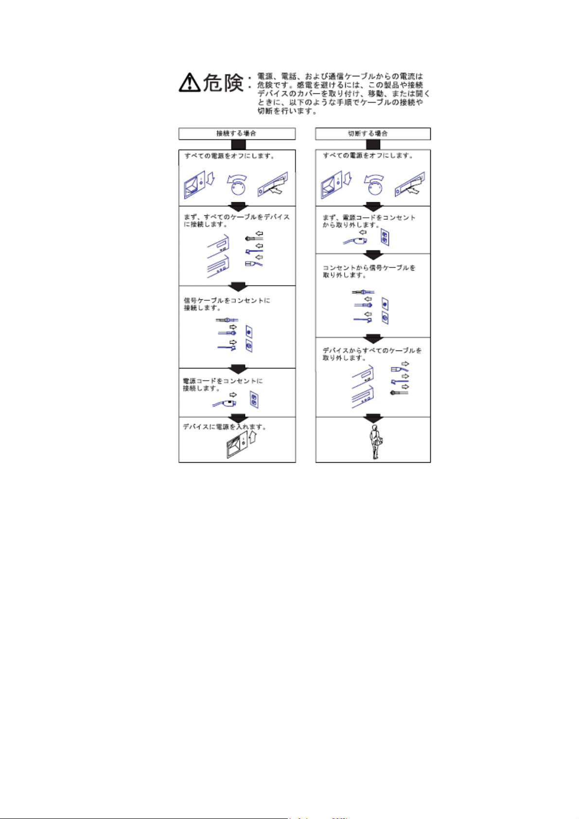
Safety Information for Users
Safety Instructions vii
Page 8
Safety Information for service personnel
Before you begin to install or service this product, please read the following safety
information.
Note: In these notices, the term, qualified service personnel, refers to a person with the
skills to perform
_________________________________________________________________________________________
a PC upgrade.
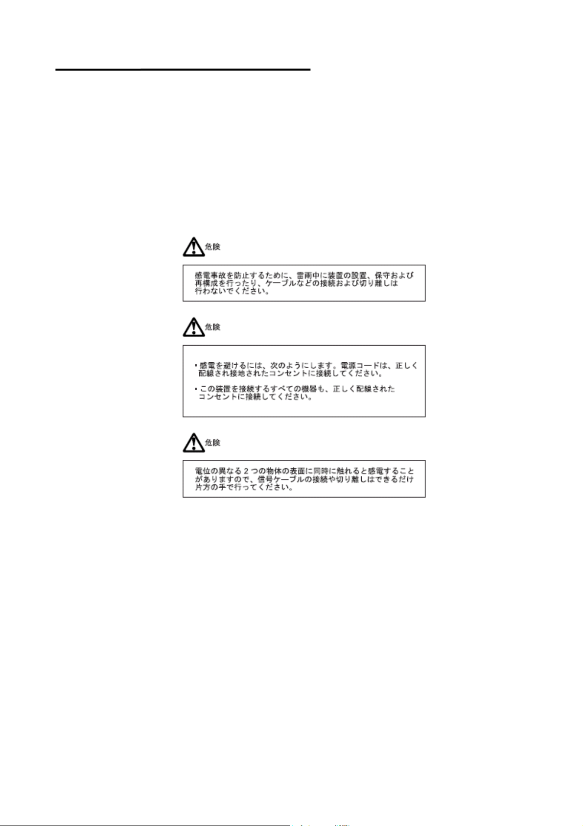
Safety Information for Japan
viii IBM 4685-K03 Installation, Operation and Maintenance Guide
Page 9
Safety Instructions ix
Page 10
_________________________________________________________________________________________
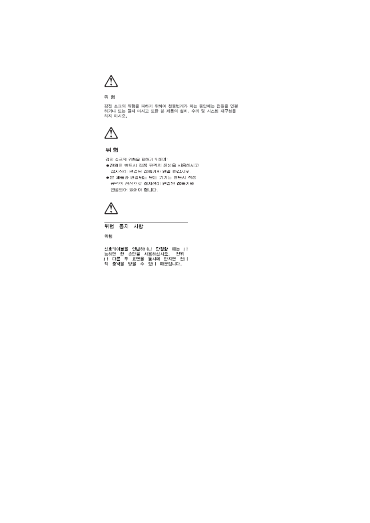
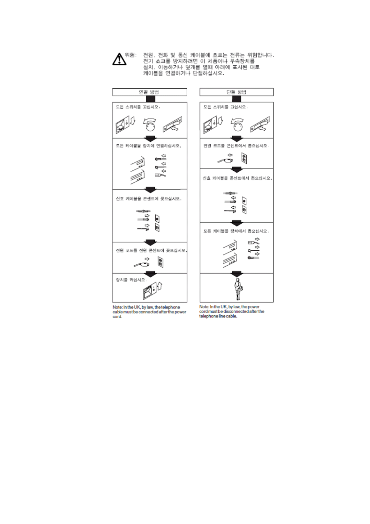
Safety Information for Korea
x IBM 4685-K03 Installation, Operation and Maintenance Guide
Page 11
Safety Instructions xi
Page 12

Page 13

Contents
INTRODUCTION ..................................................................................................................................................................... III
WHO SHOULD USE THIS GUIDE........................................................................................................................................ III
END OF LIFE DISPOSAL ...................................................................................................................................................... III
NOTICES.................................................................................................................................................................................. IV
ELECTRONIC EMISSION NOTICES ................................................................................................................................................IV
Japanese Voluntary Control Council for Interference (VCCI) Statement
Korean Communications Statement
ELECTROSTATIC DISCHARGE (ESD)........................................................................................................................................... IV
RELATED PUBLICATIONS..................................................................................................................................................... V
SAFETY INFORMATION FOR USERS...............................................................................................................................VII
SAFETY INFORMATION FOR SERVICE PERSONNEL................................................................................................ VIII
SAFETY INFORMATION FOR JAPAN ............................................................................................................................. VIII
SAFETY INFORMATION FOR KOREA ................................................................................................................................. X
CHAPTER 1 “AN OVERVIEW OF THE IBM 4685-K03 POS KEYBOARD”......................................................................1
AN OVERVIEW ..........................................................................................................................................................................1
CONFIRMATION OF PRODUCT .............................................................................................................................................2
4685-K03 MODEL........................................................................................................................................................................2
PARTS NAME ............................................................................................................................................................................2
.............................................................................................................................. iv
............................................................... iv
4685-K03 MODEL ........................................................................................................................................................................ 2
KEY LAYOUT AT SHIPMENT TIME ........................................................................................................................................3
4685-K03 MODEL ........................................................................................................................................................................ 3
CHAPTER 2 “INSTALLING THE KEYBOARD”....................................................................................................................5
INSTALLATION FOR IBM 4800 POS TERMINAL.................................................................................................................5
CHAPTER 3 “OPERATING THE KEYBOARD”....................................................................................................................9
SYSTEM KEYS ..........................................................................................................................................................................9
VOLUME ADJUSTMENT..........................................................................................................................................................9
MODE SWITCH........................................................................................................................................................................11
4-POSITION MODE KEY ................................................................................................................................................................ 11
HOW TO SWIPE A CARD THROUGH THE MSR .............................................................................................................. 12
Contents xiii
Page 14

DAILY CARE............................................................................................................................................................................ 12
CHAPTER 4 “REPLACING THE KEYS”............................................................................................................................. 15
REPLACING A SINGLE KEY ................................................................................................................................................ 15
REMOVAL.................................................................................................................................................................................... 15
ATTACHING .................................................................................................................................................................................16
REPLACING A DOUBLE KEY.............................................................................................................................................. 17
REMOVAL.................................................................................................................................................................................... 17
ATTACHING .................................................................................................................................................................................18
REPLACING A QUADRUPLE KEY...................................................................................................................................... 19
REMOVAL.................................................................................................................................................................................... 19
ATTACHING .................................................................................................................................................................................19
CHAPTER 5 “MAINTENANCE OF THE KEYBOARD”..................................................................................................... 21
IF PROBLEMS OCCUR ......................................................................................................................................................... 21
DIAGNOSTIC TESTS............................................................................................................................................................. 22
SELF-DIAGNOSTIC TESTS............................................................................................................................................................22
REMOVING AND REPLACING PARTS............................................................................................................................... 24
REPLACING THE REAR COVER.................................................................................................................................................... 24
REPLACING THE CONTROL CARD ...............................................................................................................................................25
REPLACING THE MSR................................................................................................................................................................ 25
REPLACING THE MODE KEY ........................................................................................................................................................ 27
REPLACING THE SPEAKER.......................................................................................................................................................... 27
REPLACING THE TOP COVER ASSEMBLY.....................................................................................................................................27
BILL OF MATERIAL ............................................................................................................................................................... 28
ASSEMBLY: KEYBOARD..............................................................................................................................................................28
APPENDIX A. ACCESSORY UNIT....................................................................................................................................... 31
ACCESSORY UNITS .....................................................................................................................................................................31
APPENDIX B. PRODUCT SPECIFICATIONS..................................................................................................................... 33
DIMENSIONS ...............................................................................................................................................................................33
CONSUMPTION CURRENT ...........................................................................................................................................................33
ENVIRONMENT CONDITION..........................................................................................................................................................33
MSR READABLE CARDS..................................................................................................................................................... 33
xiv IBM 4685-K03 Installation, Operation and Maintenance Guide
Page 15
Chapter 1 “An overview of the IBM 4685-K03 POS Keyboard”
This chapter provides an overview of the IBM 4685-K03 POS Keyboard, explains how to
confirm the identification of the product, gives the names of the parts, and describes the key
layout at time of shipment.
_________________________________________________________________________________________
An overview
The IBM 4685-K03 POS keyboard is equipped with an MSR (Magnetic Stripe Reader). The
4685-K03 keyboard is to be connected to an IBM 4800 POS terminal. This keyboard
connects using the IBM RS-485 or powered USB, but using both interfaces at the same
time is not supported.
Connecting two different interface cables at the same time may
damage the keyboard.
The primary hardware configuration for the 4685-K03 is as follows:
Key matrix 12 rows × 7 columns
At shipment Single keys
Double keys
MSR Read only
Mode key 4 positions
Interfaces RS-485, Powered USB
54 pieces
4 pieces
4685-K03
Chapter1 Outline for 4685-K03 POS Keyboard 1
Page 16

_________________________________________________________________________________________
Confirmation of product
Confirm the following parts are included.
4685-K03 Model
□ Mode keys Label 1
□ 4685-K03 Keyboard
□ Keys 1 set
(Single keys: 54 pieces
Double keys: 4 pieces)
□ Mode keys
Operator Key (“OP”) 2 pieces
Manager Key (“MGR”) 2 pieces
□ Removal tool for key caps
2 IBM 4685-K03 Installation, Operation and Maintenance Guide
Page 17

Page 18
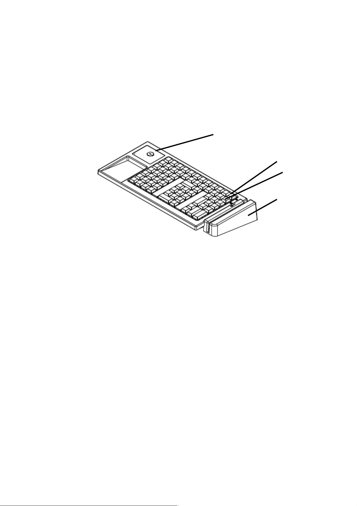
_________________________________________________________________________________________
Parts name
4685-K03 model
Mode switch
System keys
S1
S2
MSR
2 IBM 4685-K03 Installation, Operation and Maintenance Guide
Page 19

_________________________________________________________________________________________
Key layout at shipment time
4685-K03 model
Chapter 1 Outline for IBM 4685-K02 POS Keyboard 3
Page 20

Page 21
Chapter 2 “Installing the keyboard”
This section explains how the Keyboard is installed on the IBM 4800 POS terminal.
_________________________________________________________________________________________
Installation for IBM 4800 POS terminal
This section explains how Keyboard is installed on the IBM 4800 POS terminal (also referred to
as the system device).
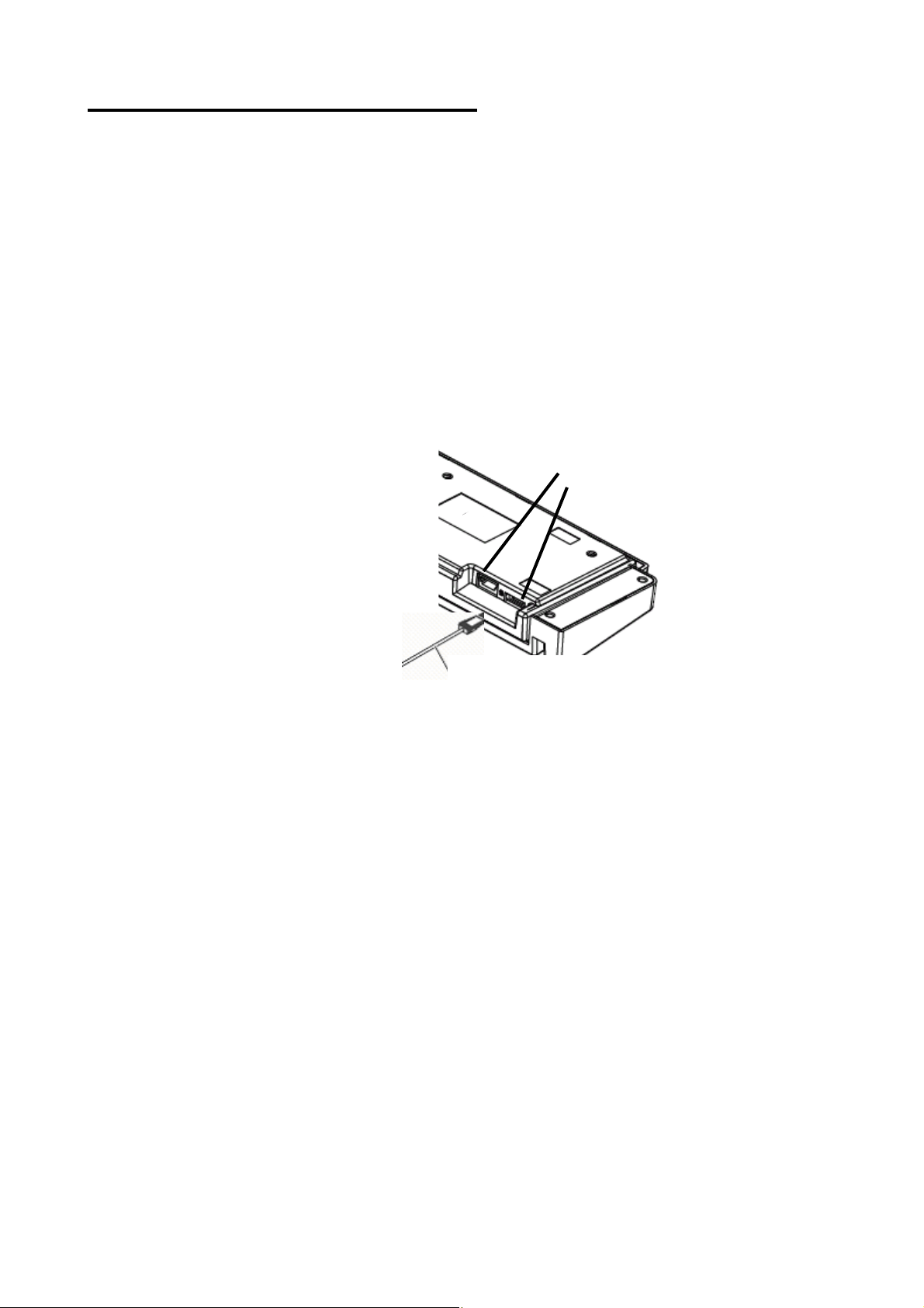
1. Connect the keyboard cable 5 to the keyboard.
Notes:
a. Turning the keyboard over and looking from the front side, connect the keyboard
cable 5 to the right side socket of the two connections.
Connector
Keyboard cable 5
b. If also installing the video display, it should be installed before going on to Step 2. After
the display is connected, continue with Step 2, “With the video display”. (See the
instruction manual that comes with the IBM 4800 POS terminal for more information
about how to install the video display.)
2. Plug the other connector on the keyboard cable into the system device as shown in the
following figure, routing it through the back side of the system device.
Chapter 2 Installing the keyboard 5
Page 22

With the video display
Without the video display
3. Put the keyboard in place on the system device.
6 IBM 4685-K03 Installation, Operation and Maintenance Guide
Page 23

4. Connect the keyboard cable to the system device. (See the instruction manual that comes
with the IBM 4800 POS terminal for more information about how to connect the keyboard
cable to the system device.)
Chapter 2 Installing the keyboard 7
Page 24

Page 25

Chapter 3 “Operating the keyboard”
This chapter explains the operating procedures and the functions of the parts.
_________________________________________________________________________________________
System keys
The system keys are used to input system functions, which are run under the control of a
program. Regarding the usage of these keys, please refer to the operating manual in your
store or call your system representatives.
The layout of the system keys is shown in the following chart.
System keys
S1
S2
_________________________________________________________________________________________
Volume adjustment
The volume adjustment adjusts the speaker volume when keys are pressed. To maximize
the volume, turn the volume adjustment control all the way to the right. To minimize the
sound, turn it all the way to the left.
MAX
MIN
Chapter 3 Operating the keyboard 9
Page 26

Notes:
1. Use your fingers, not a tool, when adjusting the speaker volume.
2. The volume adjustment control is on the bottom of the keyboard. The speaker volume
should be set when installing the keyboard on the system device.
10 IBM 4685-K03 Installation, Operation and Maintenance Guide
Page 27

_________________________________________________________________________________________
Mode switch
The key-controlled mode switch is used to select the operating mode of the 4685-K03.
The mode switch has four positions that are selected with mode keys. Both the operator
key and manager key will control the switch. A mode key cannot be removed unless the
current mode is set to “Inactive” or “Operator”.
4-position mode key
Operator (“OP”) key:
Manager ‘(”MGR”) key:
Mode Meaning
SYS
(System)
・
(Inactive)
OPE
(Operator)
MGR
(Manager)
When setting up items and terminal
addresses by using the application
program, select this mode.
Keyboard functions are disabled. Selectable Selectable
Normal operating mode Selectable Selectable
The store manager or designated
person can use this mode for special
operations, such as canceling a
transaction or changing prices, etc.
This key can select two modes: “Inactive,” “Operator.”
The letter “A” is engraved on this key.
This key can select all four modes.
The letter “H” is engraved on this key.
Inactive
System
SYS
Operator
(“OP”) key
Not
selectable
Not
selectable
Operator
OPE
Manager
MGR
Manager
‘(”MGR”) key
Selectable
Selectable
Chapter 3 Operating the keyboard 11
Page 28

________________________________________________________________________________________
How to swipe a card through the MSR
This section explains how to swipe a card through the MSR (magnetic stripe reader).
1. Hold the card horizontally with the stripe at the bottom and facing away from the
keyboard.
2. Position the card at the farther end of the MSR and swipe the card through the slot
toward the operator with a smooth, steady motion.
_________________________________________________________________________________________
Front (raised embossing) side
Back side
Daily care
z Stains on plastic parts should to be wiped off with a soft, dry cloth. Wiping with a wet or
oily cloth can cause damage to the electronic components or plastic parts.
z Do not use chemicals such as glass cleaners, ammonia, acetone, or ketene. To
remove ink stains, use a soft cloth with a small amount of a mild detergent.
12 IBM 4685-K03 Installation, Operation and Maintenance Guide
Page 29

Chapter 3 Operating the keyboard 13
Page 30

Page 31
Chapter 4 “Replacing the keys”
You are free to change the layout of the keys except for the ten keys of the numeric keypad.
For example, frequently used keys can be made into larger double keys by replacing two
single keys with one double key.
This chapter explains how to replace single keys, double keys, quadruple keys, and
unused key covers on the keyboard.
Before replacing keys, put the POS terminal into standby mode
(system lamp off) by pushing the standby button.
_________________________________________________________________________________________
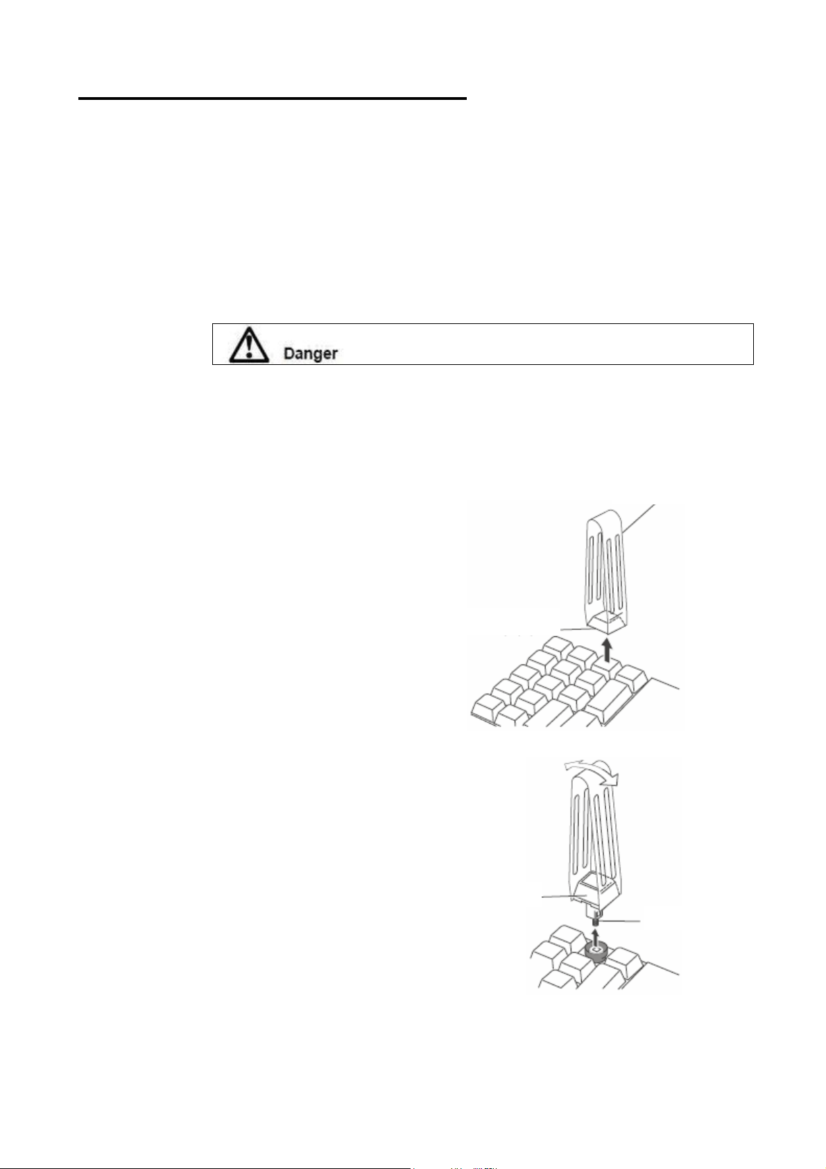
Replacing a single key
Removal
1. Pinch the key cap lightly with the removal tool,
and pull it up, rocking it to the left and right.
2. Pull out the key in the same way as the key cap.
Be careful not to bend the spring attached to the
key.
Key cap
Removal tool
Key
Spring
Chapter 4 Replacing the key 15
Page 32

3. Remove the black rubber ring.
Attaching
1. Insert the black rubber ring. Insert the cup with the
larger opening facing up.
Rubber ring (Black)
Rubber ring (Black)
2. Insert the key. Be careful not to bend the spring
attached to the key.
3. Attach the key.
Key
Spring
16 IBM 4685-K03 Installation, Operation and Maintenance Guide
Page 33

_________________________________________________________________________________________
Replacing a double key
Removal
1. Pull off the key cap with the removal tool. (See
“Replacing a single key” on page 17.)
2. Pinch the key lightly with the removal tool, and
pull it out. Be careful not to bend the
attached to the key.
3. Remove the two rubber rings (black and brown).
springs
Key
Spring
Rubber rings
Removal tool
4. Remove the key guide by using the opposite end
of the removal tool.
(Brown)
(Black)
Key guide
Chapter 4 Replacing the key 17
Page 34

Attaching
1. Insert the key guide into the hole that will
not use a scan code.
2. Insert the brown rubber ring around the
hole where the key guide was inserted.
Insert the black rubber ring at the location
without the key guide.
Key guide
(Brown)
3. Insert the key. Be careful not to bend the
springs attached to the key.
4. Attach the key.
(Black)
Key
Spring
18 IBM 4685-K03 Installation, Operation and Maintenance Guide
Page 35
_________________________________________________________________________________________
Replacing a quadruple key
Removal
The removal procedure for quadruple keys is the same as for single or double keys.
1. Pull off the key cap with the removal tool.
2. Pull off the key with the removal tool. Be careful not to bend the springs attached to the
key.
3. Remove the two black rubber rings.
4. Remove the two key guides with the opposite end of the removal tool.
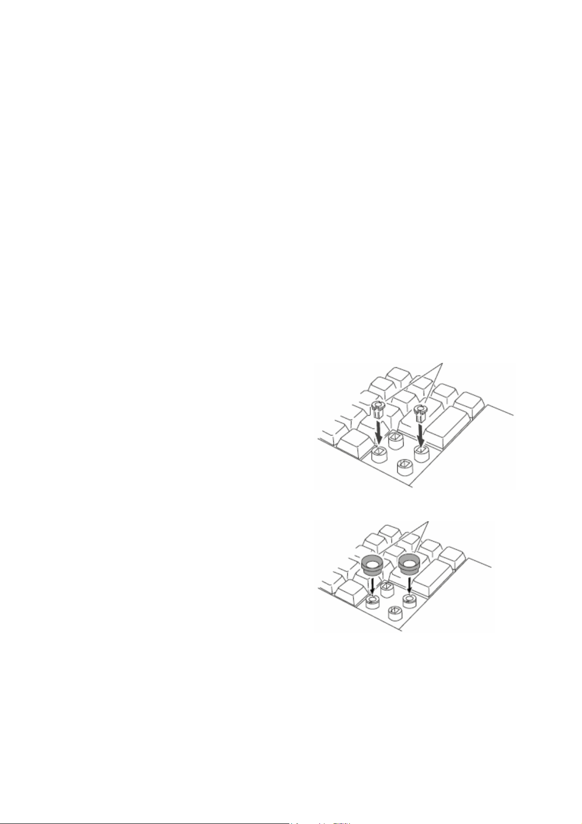
Attaching
Note: Make sure the smaller keys, the rubber rings,
and the key guides are removed from the place
where the quadruple key will be attached.
1. Find the pair of diagonally opposite holes that will
not need scan codes. Insert two key guides in
those holes.
2. Place the two black rubber rings around the key
guides.
Rubber dome (black)
Key guides
Chapter 4 Replacing the key 19
Page 36

3. Make sure the scan code leg is aligned with the
proper hole, and insert the quadruple key. Be
careful not to bend the springs attached to the key.
4. Label the key cap. Attach the key cap on top of the
key.
_________________________________________________________________________________________
Key
Spring
Replacing an unused key cover
Removal
1. Pinch the unused key cover with the removal tool.
Pull up on the unused key cover.
Removal tool
Attaching
Note: Make sure the keys, rubber rings, and key
guides are all removed from the place where the
unused key cover will be inserter.
1. Insert the unused key cover as shown in the
figure.
Key cover
Unused key
cover
20 IBM 4685-K03 Installation, Operation and Maintenance Guide
Page 37

Chapter 5 “Maintenance of the keyboard”
This section is provided for the maintainer of the IBM 4685-K03 POS keyboard.
Be sure to read “Safety instructions” on page ⅴ and “Safety inspection guide” on page ⅶ
before working on this product.
_________________________________________________________________________________________
If problems occur
This section explains how to handle problems encountered when using the IBM 4685-K03 keyboard.
Symptom Causes and actions
There is no response to
any of the keyboard keys.
There is no response to
one or several keyboard
keys.
The mode cannot be
changed with a mode key.
Cause 1
Action 1
Cause 2
Action 2
Cause 3
Cause 3
Cause
Actions
Cause
Action 1
Action 2
Status of the mode key is “Inactive”.
Select a mode other than “Inactive”. See “Mode switch” on page 13 for
more information.
The setup for the operating system (OS) had problems.
Confirm the validity of the keyboard type as set up for the OS. Check
the OS documentation for more information.
The keyboard cable, the top cover assembly, or the control card for
the keyboard has problems.
Replace the keyboard cable, then the top cover assembly, and then
the control card (until the faulty part is identified).
The key cap, the top cover assembly or the control card has troubles.
a. Identify the disabled keys by using the diagnostic program or the
self-diagnostic test. See “Diagnostic tests” on page 20 for more
information.
b. Replace the key, the unused key cover over the non-functioning
keys, or the control card. For more about replacing keys, see
Chapter 4 “Replacing a single key” on page 13. For more about
replacing unused key covers, see “Replacing an unused key cover”
on page 18.
The mode key or the control card has problems.
Check the status of the mode key switches using the diagnostic
program or the self-diagnostic test. See “Diagnostic tests” on page 20
for more information.
If the status is still unchanged by Action 1, replace the mode key or the
control card.
Chapter 5 Maintenance of the keyboard 21
Page 38

Symptom Causes and actions
The MSR is unable to read
cards.
The keyboard cannot be
switched to the online
mode.
The mode key is lost. Contact your dealer or IBM service representative.
If your problems are not resolved by these procedures, please contact an IBM service engineer.
_________________________________________________________________________________________
Cause 1
Action 1
Cause 2
Action 2
Action 3
Cause
Action
There MSR reading head needs to be cleaned.
Clean the MSR reading head by using the MSR cleaning card in the
hardware service kit (P/N: 48G9045).
The MSR or the control card has a problem.
Check if the MSR is functional using the diagnostic program or the
self-diagnostic test. See “Diagnostic test” on page 20 for more
information.
If the condition is still unchanged by Action 2, replace the MSR or the
control card.
The keyboard has problems or the OS settings are incorrect.
a. Check that the keyboard is recognized by the diagnostic program.
See “Diagnostic test” on page 20 for more information.
b. Make sure the keyboard type settings for the OS are valid. See the
OS documentation for more information.
Diagnostic tests
There are two types of diagnostic tests for 4685-K03. The testing method is different depending on POS terminals
connected to the keyboard.
1. Self-diagnostic tests
2. 4800 Diagnostic program
For more about the 4800 Diagnostic program, please see the manual. The manual is available at:
http://www.ibm.com/jp/store/
z
http://www.pc.ibm.com/store/
z
Self-diagnostic tests
Self-diagnostic tests are available for checking the functions of the keyboard. During the diagnostic tests, the
keyboard has power, but cannot communicate with the terminal. The self-diagnostic tests can be activated at any
time, unless the mode key position is “Inactive”.
How to enter the self-diagnostic tests
To enter the self-diagnostic tests:
1. Within 2 seconds after turning the power on, press the top left key twice.
2. The keyboard should respond with six beeps, with the frequency increasing from low to high.
3. After one more beep, the keyboard is ready for the self-diagnostic tests.
22 IBM 4685-K03 Installation, Operation and Maintenance Guide
Page 39

Mode switch test (Self-diagnostic test)
Switching the mode key switch to a new position should cause the speaker to beep once.
MSR Test (Self-diagnostic test)
If a magnetic card is scanned through the MSR, the speaker should beep twice.
Key Input Test (Self-diagnostic test)
Pressing any key should cause the speaker to beep twice.
Note: This test does not work if the position of the mode key is pointing at “Inactive”. The mode key switch must be
in one of the other positions.
How to terminate the self-diagnostic tests
To terminate the self-diagnostic tests, turn off the POS terminal by pressing the standby switch.
Chapter 5 Maintenance of the keyboard 23
Page 40

_________________________________________________________________________________________
Removing and replacing parts
Replacing the rear cover
1. Remove the 7 screws labeled 1. Remove the rear cover 2.
Reverse the procedure to reassemble.
1
2
24 IBM 4685-K03 Installation, Operation and Maintenance Guide
Page 41

Replacing the control card
f
f
f
fOffOff
1. Remove the rear cover. See “Replacing the rear cover” on page 22.
2. Remove the screw labeled 2 which holds the ground cable 1 and the cover.
3. Open the cover. Disconnect the cables of two sheets for the membrane 4 and the other connectors from the
control card 3.
4. Remove the four screws labeled 5. Remove the control card 3.
Reverse the procedure to reassemble.
4
6
5
2
3
1
Dip Switch Setting
Before you replace the control card, please check the Dip Switch (S1) 6 setting on the control card.
On
Of
1234
POS Keyboard Model 1 2 3 4
4685-K03 Of
4685-K02 Of
On On Of
On
Replacing the MSR
1. Remove the rear cover. See “Replacing the rear cover” on page 22.
2. Remove the two screws labeled 2 which hold the MSR 1 in place.
3. Disconnect the cable leading to the control card. Remove the MSR 1.
Reverse the procedure to reassemble.
Chapter 5 Maintenance of the keyboard 25
Page 42

2
1
26 IBM 4685-K03 Installation, Operation and Maintenance Guide
Page 43

Replacing the mode key
1. Detach the guide label. Remove the two screws labeled 1
2. Remove the rear cover. See “Replacing the rear cover” on page 22.
3. Disconnect the cable leading to the control card. Remove the mode key 2.
Reverse the procedure to reassemble. Use the new guide label attached to the FRU.
1
2
Replacing the speaker
1. Remove the rear cover. See “Replacing the rear cover” on page 22.
2. Open the two latches labeled 1 that hold the speaker in place.
3. Disconnect the cable labeled 2 from the control card. Remove the speaker3.
Reverse the procedure to reassemble.
Replacing the top cover assembly
1. Remove the rear cover. See “Replacing the rear cover” on page 22.
2. Remove the control card. See “Replacing the control card” on page 23.
3. Remove the speaker. See “Replacing the speaker.”
4. Remove the MSR. See “Replacing the MSR” on page 23.
5. Remove the mode key. See “Replacing the mode key” on this page.
6. Use the new guide label attached to the FRU.
7. Replace the key labels.
Reverse the procedure to reassemble.
Chapter 5 Maintenance of the keyboard 27
Page 44
_________________________________________________________________________________________
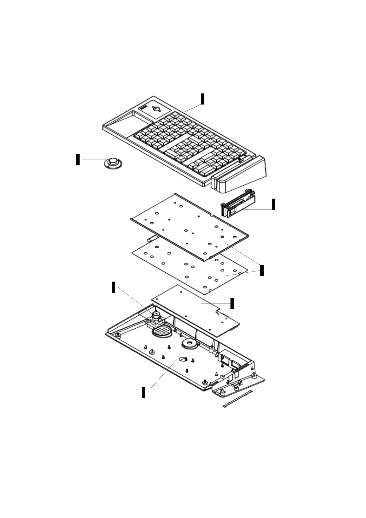
Bill of material
Assembly: Keyboard
3
6
4
5
3
2
1
28 IBM 4685-K03 Installation, Operation and Maintenance Guide
Page 45

ASM-Index Part Number Unit Description
POS Keyboard Unit, 4685-K03
1
2
3
4
5
6
29R0782
29R0784
29R0786
29R0783
29R0785
29R0787
29R0788
07N1027
z Bottom Cover Asm
1
z Control Card Asm
1
z Top Cover, Asm
1
z Magnetic Stripe Reader (MSR) with MSR Cable
1
z 4 position Mode Key Switch Asm with Cable
1
z Speaker Asm
1
z Ten Key for 4685-K02/K03
07N1032
07N1033
48G9045
29R0789
z Key 1x1 (5 sets)
z Key 1x2 (5 sets)
z Hardware Service Kit
— MSR Cleaning Card
— MSR Test Card
z Dummy Cover 1x5
Chapter 5 Maintenance of the keyboard 29
Page 46

30 IBM 4685-K03 Installation, Operation and Maintenance Guide
Page 47

_________________________________________________________________________________________
Appendix A. Accessory unit
You should order accessory units from an IBM sales representative or your dealer.
Accessory units
Item number Name Content Quantity
3891 Key (Single) Key (Single)
Key cap (Single)
Key rubber ring 50 g
3892 Key (Double) Key (Double)
Key cap (Double)
black rubber ring 50 g
Key
Key brown rubber ring 20 g
Key guide
3893 Key (Quadruple) Key (Quadruple)
Key cap (Quadruple)
Key black rubber ring 50 g
Key guide
3894 Key cover (Single) Key cover (Single) 10 sets
3895 Key cover (1x5) Key cover (1x5) 5 sets
3896 Mode key Manager key
Operator key
3897 H/W Service Kit MSR Cleaning Card
JIS-I/II Test Card
3325 KBD SIO Cable-Short 0.48m 1 Piece
3326 KBD SIO Cable-Long 3.8m 1 Piece
3327 KBD SIO Cable-Medium 1.8m 1 Piece
3290 KBD USB Cable-Short 0.5m 1 Piece
3285 KBD USB Cable-Long 3.8m 1 Piece
10 sets
10 sets
10 sets
10 sets
10 sets
10 sets
10 sets
10 sets
10 sets
10 sets
20 sets
20 sets
2 pieces
2 pieces
1 Piece
1 Piece
Appendix B. Field replaceable units 31
Page 48

32 IBM 4685-K03 Installation, Operation and Maintenance Guide
Page 49

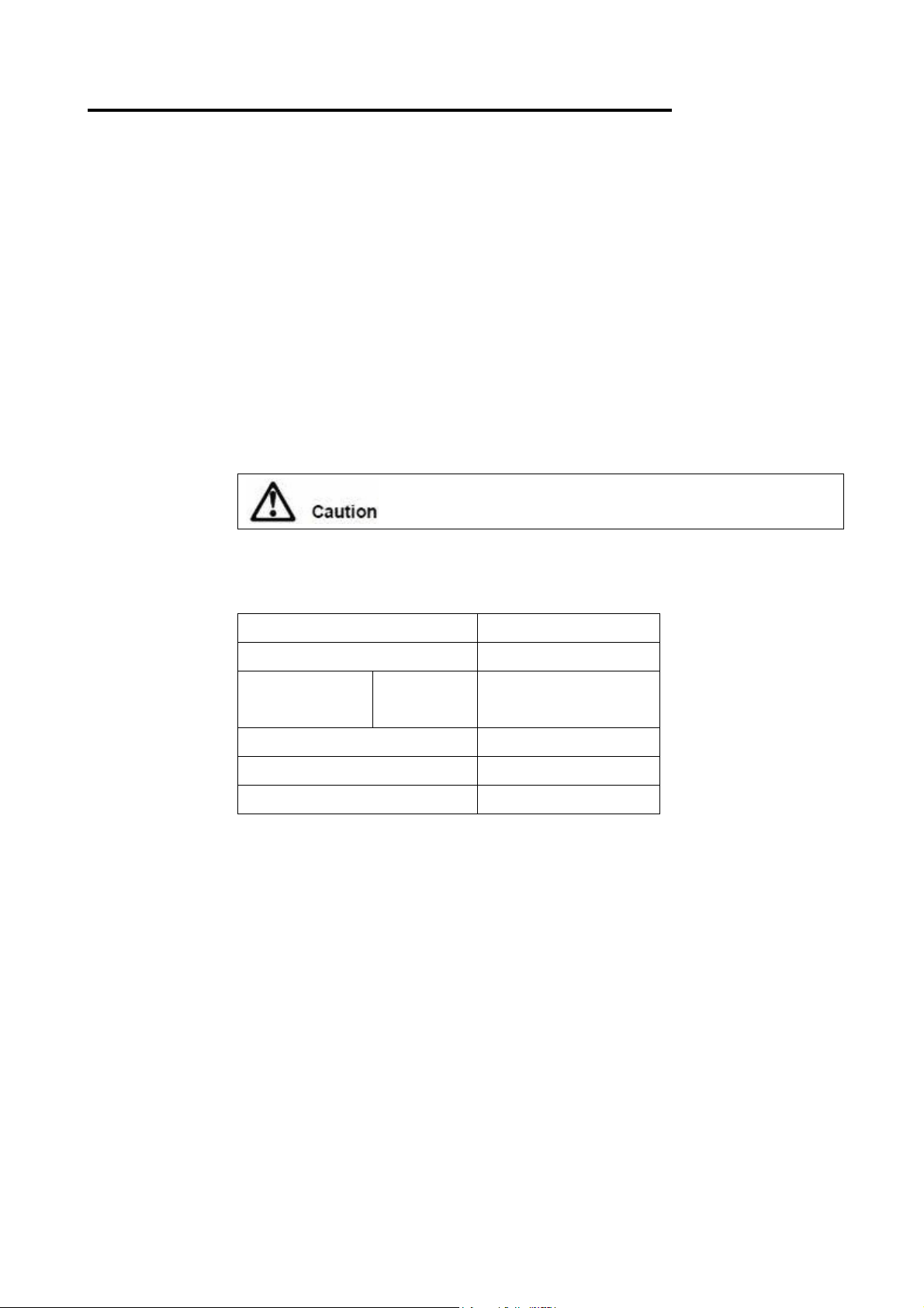
Appendix B. Product specifications
Dimensions
Width 365 mm
Depth 170 mm
Height 50 mm
Weight 1.1 Kg
Consumption current
Peak: 400 mA
Normal: 100 mA
Environment condition
Condition
4685-K03
Temperature(℃)
Humidity (%)
Max wet bulb
temperature(℃)
Operating
Standby
Storage
Shipping
_________________________________________________________________________________________
0 ~ +40 8 ~ 90
0 ~ +43 8 ~ 90
10 ~ +60 5 ~ 95
40 ~ +60 5 ~ 100
+23
+27
+29
+29
MSR readable cards
Compatible MSR cards are described in the following chart.
ISO/JIS I
Card specifications
Record density 210 BPI (Bit Per Inch) 75 BPI
Record capacity 72 digits (8 bits) 40 digits (5 bits)
Recording method FM FM
Read/Write Readable Readable
JIS Ⅱ
Track 2
Page 50

Printed in Japan
IBM Japan, Ltd.
〒106-8711 Roppongi 3-2-12, Minato-ku, Tokyo
 Loading...