

Page 1

4613 SurePOS 100 Point-of-Sale Terminal
Installation an d Operation Manual
GA27-4368-00July 27, 2007 - Approval Draft
Page 2

Page 3

4613 SurePOS 100 Point-of-Sale Terminal
Installation an d Operation Manual
GA27-4368-00July 27, 2007 - Approval Draft
Page 4

July 27, 2007 - Approval Draft
Note
Before using this information and the product it supports, read the information in Appendix D, “Safety information,” on page
49 and Appendix E, “Notices,” on page 55 on page 59 .
August 2007
This edition applies to the 4613 SurePOS 100 series point-of-sale terminals and to all subsequent releases of this
product until otherwise indicated in new editions. Retail Store Solutions documentation are available on the IBM
Retail Store Solutions Web site at http://www.ibm.com/solutions/retail/store/support.
A form for reader’s comments is also provided at the back of this publication. If the form has been removed, address
your comments to:
IBM Corporation
Retail Store Solutions Information Development
Department ZBDA
PO Box 12195
Research Triangle Park, North Carolina 27709 USA
you send information to IBM, you grant IBM a nonexclusive right to use or distribute whatever information you
When
supply in any way it believes appropriate without incurring any obligation to you.
© Copyright International Business Machines Corporation 2007. All rights reserved.
US Government Users Restricted Rights – Use, duplication or disclosure restricted by GSA ADP Schedule Contract
with IBM Corp.
Page 5

July 27, 2007 - Approval Draft
Contents
Tables . . . . . . . . . . . . . . . . . . . . . . . . . . . .v
Figures . . . . . . . . . . . . . . . . . . . . . . . . . . . vii
About this Guide . . . . . . . . . . . . . . . . . . . . . . . .ix
Who Should Read This Guide . . . . . . . . . . . . . . . . . . . .ix
How This Guide Is Organized . . . . . . . . . . . . . . . . . . . .ix
Related Publications . . . . . . . . . . . . . . . . . . . . . . .ix
Store System Library . . . . . . . . . . . . . . . . . . . . . .ix
Related Software . . . . . . . . . . . . . . . . . . . . . . . .ix
Publications accessibility . . . . . . . . . . . . . . . . . . . . . .x
Providing feedback . . . . . . . . . . . . . . . . . . . . . . . .x
Chapter 1. Getting Started . . . . . . . . . . . . . . . . . . . .1
Overview . . . . . . . . . . . . . . . . . . . . . . . . . . .1
IBM 4613 SurePOS 100 Point-of-Sale Model Specifications . . . . . . . .2
Power Requirements and Consumption . . . . . . . . . . . . . . .3
Models and Features . . . . . . . . . . . . . . . . . . . . . .4
Additional Features . . . . . . . . . . . . . . . . . . . . . . .6
Connector Locations . . . . . . . . . . . . . . . . . . . . . .7
Chapter 2. Installation Instructions . . . . . . . . . . . . . . . . .9
System Features . . . . . . . . . . . . . . . . . . . . . . . . .9
Safety Notices . . . . . . . . . . . . . . . . . . . . . . . . .9
Unpacking the SurePOS 100 . . . . . . . . . . . . . . . . . . . .10
Customizing the Base Unit . . . . . . . . . . . . . . . . . . . .10
Installing the SurePOS 100 . . . . . . . . . . . . . . . . . . . .11
Configuring the Keyboard . . . . . . . . . . . . . . . . . . . . .13
Installing the Customer Display . . . . . . . . . . . . . . . . . . .13
Quad Key . . . . . . . . . . . . . . . . . . . . . . . . . . .16
Riser Card . . . . . . . . . . . . . . . . . . . . . . . . . .16
Chapter 3. SurePOS 100 Operations . . . . . . . . . . . . . . . .17
Operational Components . . . . . . . . . . . . . . . . . . . . .17
System Unit Controls and Indicators . . . . . . . . . . . . . . . . .18
Monochrome Video Display Controls and Indicators . . . . . . . . . . .19
Color LCD Display Controls and Indicators . . . . . . . . . . . . . . .21
Video modes . . . . . . . . . . . . . . . . . . . . . . . .22
Adjusting the image . . . . . . . . . . . . . . . . . . . . . .23
Keylock Operation . . . . . . . . . . . . . . . . . . . . . . . .25
Operating the Card Reader . . . . . . . . . . . . . . . . . . . .25
Impact Printer Operating Controls and Indicators . . . . . . . . . . . .26
Loading the Impact Printer Ribbon . . . . . . . . . . . . . . . . .27
Loading the Impact Printer Paper . . . . . . . . . . . . . . . . .28
Thermal Printer Operating Controls and Indicators . . . . . . . . . . . .29
Loading Thermal Printer Paper . . . . . . . . . . . . . . . . . .30
Optional Features Operation . . . . . . . . . . . . . . . . . . . .32
Customer Display Head . . . . . . . . . . . . . . . . . . . .32
Cash Drawer . . . . . . . . . . . . . . . . . . . . . . . .32
Chapter 4. Adjusting System Configuration . . . . . . . . . . . . .35
Configuration Options . . . . . . . . . . . . . . . . . . . . . .35
Configuring the System Unit . . . . . . . . . . . . . . . . . . . .35
© Copyright IBM Corp. 2007 iii
Page 6

July 27, 2007 - Approval Draft
Chapter 5. Installation Testing and Problem Analysis . . . . . . . . .37
Performing Tests . . . . . . . . . . . . . . . . . . . . . . . .37
Safety Notices . . . . . . . . . . . . . . . . . . . . . . . . .37
Testing Your Installation . . . . . . . . . . . . . . . . . . . . . .37
Problem Analysis . . . . . . . . . . . . . . . . . . . . . . . .39
Preliminary Troubleshooting . . . . . . . . . . . . . . . . . . .39
Problem Analysis Procedure . . . . . . . . . . . . . . . . . . .39
Appendix A. Service diagnostics, device drivers, and diagnostic
information . . . . . . . . . . . . . . . . . . . . . . . . .43
POS Device Tests . . . . . . . . . . . . . . . . . . . . . . . .43
System Utility Tests . . . . . . . . . . . . . . . . . . . . . . .43
Viewing Configuration . . . . . . . . . . . . . . . . . . . . . .43
Printer Test Patterns . . . . . . . . . . . . . . . . . . . . . . .44
Appendix B. System Cleaning Information . . . . . . . . . . . . . .45
Customer User Product Care Procedures . . . . . . . . . . . . . . .45
Service Provider System Maintenance Procedures . . . . . . . . . . . .46
Appendix C. Printer Supplies . . . . . . . . . . . . . . . . . . .47
Appendix D. Safety information . . . . . . . . . . . . . . . . . .49
Appendix E. Notices . . . . . . . . . . . . . . . . . . . . . .55
Electronic emission notices . . . . . . . . . . . . . . . . . . . .57
Federal Communications Commission (FCC) statement . . . . . . . . .57
European Union EMC Directive conformance statement . . . . . . . . .57
Industry Canada Class A Emission Compliance statement . . . . . . . .58
Avis de conformité aux normes d’Industrie Canada . . . . . . . . . .58
Germany . . . . . . . . . . . . . . . . . . . . . . . . . .58
Australia and New Zealand . . . . . . . . . . . . . . . . . . .58
Chinese Class A warning statement . . . . . . . . . . . . . . . .59
Japanese power line harmonics compliance statement . . . . . . . . .59
Japanese Voluntary Control Council for Interference (VCCI) statement . . .59
Korean communications statement . . . . . . . . . . . . . . . .59
Taiwanese Class A warning statement . . . . . . . . . . . . . . .60
Taiwan contact information . . . . . . . . . . . . . . . . . . . .60
Taiwanese battery recycling statement . . . . . . . . . . . . . . . .60
Cable ferrite requirement . . . . . . . . . . . . . . . . . . . . .60
Electrostatic Discharge (ESD) . . . . . . . . . . . . . . . . . . .60
End of life disposal . . . . . . . . . . . . . . . . . . . . . . .61
Trademarks . . . . . . . . . . . . . . . . . . . . . . . . . .62
Index . . . . . . . . . . . . . . . . . . . . . . . . . . . .63
iv 4613 SurePOS 100 Point-of-Sale Terminal: Installation and Operation Manual
Page 7

July 27, 2007 - Approval Draft
Tables
1. 4613 Specifications . . . . . . . . . . . . . . . . . . . . . . . . . . . . . .2
2. Power Input . . . . . . . . . . . . . . . . . . . . . . . . . . . . . . . . .3
3. Power Consumption . . . . . . . . . . . . . . . . . . . . . . . . . . . . . .3
4. Port Power Ratings . . . . . . . . . . . . . . . . . . . . . . . . . . . . . .3
5. Supported video modes . . . . . . . . . . . . . . . . . . . . . . . . . . . .22
6. Troubleshooting Common Problems . . . . . . . . . . . . . . . . . . . . . . . .39
© Copyright IBM Corp. 2007 v
Page 8

July 27, 2007 - Approval Draft
vi 4613 SurePOS 100 Point-of-Sale Terminal: Installation and Operation Manual
Page 9

July 27, 2007 - Approval Draft
Figures
1. SurePOS 100 Standard Features with Monochrome Display (model 108) . . . . . . . . . .4
2. SurePOS 100 with Color LCD Display (model 118) . . . . . . . . . . . . . . . . . . .5
3. 2x20 VFD Customer Display . . . . . . . . . . . . . . . . . . . . . . . . . . .6
4. 1x11 LED Customer Display . . . . . . . . . . . . . . . . . . . . . . . . . . .6
5. Quad Key . . . . . . . . . . . . . . . . . . . . . . . . . . . . . . . . . .6
6. System Unit Cable and Port Connector Locations . . . . . . . . . . . . . . . . . . .7
7. Customer Display Tower . . . . . . . . . . . . . . . . . . . . . . . . . . . .14
8. Quad Key on Keyboard . . . . . . . . . . . . . . . . . . . . . . . . . . . .16
9. SurePOS 100 System Unit – Indicators and Controls . . . . . . . . . . . . . . . . .18
10. SurePOS 100 Video Display – Front Indicators and Controls . . . . . . . . . . . . . . .19
11. SurePOS 100 Video Display Back Panel Controls . . . . . . . . . . . . . . . . . . .20
12. LCD Indicator locations on the bottom front of the color LCD display . . . . . . . . . . . .21
13. Button and connector locations on the bottom–underside of the color LCD display . . . . . . .22
14. Adjusting the display, pictorial view . . . . . . . . . . . . . . . . . . . . . . . .23
15. Brightness Menu . . . . . . . . . . . . . . . . . . . . . . . . . . . . . . .23
16. SurePOS 100 Keylock Positions . . . . . . . . . . . . . . . . . . . . . . . . .25
17. Sliding a Card Along a Card Reader . . . . . . . . . . . . . . . . . . . . . . . .25
18. SurePOS 100 Impact Printer - Indicators and Controls . . . . . . . . . . . . . . . . .26
19. Opening the Printer Cover . . . . . . . . . . . . . . . . . . . . . . . . . . .27
20. Loading Path for Impact Printer Paper . . . . . . . . . . . . . . . . . . . . . . .28
21. SurePOS 100 Thermal Printer - Indicators and Controls . . . . . . . . . . . . . . . .29
22. Automatically Loading the Thermal Printer . . . . . . . . . . . . . . . . . . . . .30
23. Closing and Replacing the Printer Cover . . . . . . . . . . . . . . . . . . . . . .31
24. Adjusting the Customer Display Head . . . . . . . . . . . . . . . . . . . . . . .32
25. Cash Drawer Keylock Positions . . . . . . . . . . . . . . . . . . . . . . . . .33
26. Cash Drawer Document Storage . . . . . . . . . . . . . . . . . . . . . . . . .33
27. Compact Cash Drawer Coin Roll Opener . . . . . . . . . . . . . . . . . . . . . .33
28. Powering On the SurePOS 100 . . . . . . . . . . . . . . . . . . . . . . . . .38
29. Printer Test Patterns . . . . . . . . . . . . . . . . . . . . . . . . . . . . .44
© Copyright IBM Corp. 2007 vii
Page 10

July 27, 2007 - Approval Draft
viii 4613 SurePOS 100 Point-of-Sale Terminal: Installation and Operation Manual
Page 11

July 27, 2007 - Approval Draft
About this Guide
Use this document to install and use the IBM 4613 SurePOS 100® Point-of-Sale
Terminal.
Who Should Read This Guide
This document is intended for the person who will install, set up, and use the IBM
SurePOS 100 series models 108 and 118.
How This Guide Is Organized
This manual contains the following chapters:
v Chapter 1, “Getting Started” provides general information about the SurePOS
100.
v Chapter 2, “Installation Instructions” provides procedures for unpacking and
installing the SurePOS 100.
v Chapter 3, “SurePOS 100 Operations” provides feature overview information, and
removal and replacement procedures.
v Chapter 4, “Adjusting System Configuration” provides information describing how
to adjust the system configuration.
v Chapter 5, “Installation Testing and Problem Analysis” provides testing and
problem analysis information.
Related Publications
Those using the IBM 4613 SurePOS 100 Point-of-Sale Terminal also may want to
consult the following publications:
v IBM 4613 SurePOS 100 Point-of-Sale Terminal: Hardware Service Guide,
GY27-0425
v IBM 4613 SurePOS 100 Point-of-Sale Terminal: Operating System Installation
Guide, GC30-4158-00
information about IBM publications not shipped with the IBM 4613 SurePOS
For
100 Point-of-Sale Terminal (such as those related to similar products and offerings),
contact your IBM representative or your place of purchase.
Store System Library
The following IBM publications are available from the IBM Retail Store Solutions
Web site. To access these publications, go to http://www.ibm.com/solutions/retail/
store. Select Support. Click Publications.
v IBM Point of Sale Subsystem for DOS: Programming Reference, SC30-3621
v IBM Point of Sale Subsystem: Programming Reference and User’s Guide,
SC30-3560
Related Software
Utility software, LAN drivers, video drivers, and diagnostic software are available. To
access this software: See the latest list on the IBM Retail Store Solutions Web site
at http://www.ibm.com/solutions/retail/store. Select Support. Click Software.
© Copyright IBM Corp. 2007 ix
Page 12

Publications accessibility
The soft-copy version of this guide and other related publications are
accessibility-enabled.
Providing feedback
Your feedback is important in helping IBM provide accurate and high-quality
information.
You can use either of these ways to provide feedback:
v Go to http://www.ibm.com/solutions/retail/store. Click Support, then click
Publications. Click the publication comments within the introductory text.
Provide the requested information and your comments. Be sure to include the
name and form number of the document in the [Publication ID] field.
v Print and complete the form at the end of this document. Return the form to IBM
by mail or by giving it to an IBM representative.
applicable, include a reference to the specific location of the text (for example, the
If
page or table number) on which you are commenting.
Between major revisions of this document, there might be minor technical updates.
The latest version of this document is available on the Retail Store Solutions Web
site at www.ibm.com/solutions/retail/store/support/publications/.
July 27, 2007 - Approval Draft
x 4613 SurePOS 100 Point-of-Sale Terminal: Installation and Operation Manual
Page 13

July 27, 2007 - Approval Draft
Chapter 1. Getting Started
Overview . . . . . . . . . . . . . . . . . . . . . . . . . . .1
IBM 4613 SurePOS 100 Point-of-Sale Model Specifications . . . . . . . .2
Power Requirements and Consumption . . . . . . . . . . . . . . .3
Models and Features . . . . . . . . . . . . . . . . . . . . . .4
Model 108 . . . . . . . . . . . . . . . . . . . . . . . . .4
Model 118 . . . . . . . . . . . . . . . . . . . . . . . . .5
Additional Features . . . . . . . . . . . . . . . . . . . . . . .6
Connector Locations . . . . . . . . . . . . . . . . . . . . . .7
Overview
The IBM 4613 SurePOS 100 Series Point-of-Sale Terminal is created specifically for
retailers as a dedicated POS unit. This system unit includes the computer,
keyboard, magnetic stripe reader (MSR) for card transactions, impact receipt printer
or thermal receipt printer, and a video display into one unit. Networking capability is
built into the unit so that multiple terminals can communicate with one another.
Optional features include two different customer displays, and a cash drawer. Other
optional devices and peripherals that you can connect to the unit through its
RS-232 and USB communications ports include scanners, check readers, and pin
pads.
© Copyright IBM Corp. 2007 1
Page 14

Getting Started
July 27, 2007 - Approval Draft
IBM 4613 SurePOS 100 Point-of-Sale Model Specifications
The SurePOS 100 can be ordered configured with various specifications. A
breakdown of these features is listed below.
Table 1. 4613 Specifications
Attribute Specification
Processor 2.0 GHz Via C7
Memory 256 MB DDR2 – Standard (expandable to 1 Gb)
Expansion Slot Available
Video memory Selectable 16, 32, or 64 MB UMA
HDD 80 Gb S ATA (or larger)
CD-ROM DVD Available
Printer Thermal
Impact
Monitor 9" monochrome CRT
10.4" color active matrix LCD
Keyboard 96 Key
Fully Programmable
Keycaps with Legend Sheets
Double Key
Quad-Key Keycaps Available
MSR Two Track
Keylock Three Position
Environmental RoHS Compliant
IO Ports – Front Standard USB 2.0 (1)
PS/2 Keyboard
PC Mouse
Ethernet
Cash Drawer
IO Ports – Rear Standard RS-232 (2)
Powered RS-232 (2)
Standard USB (2)
12 V Powered USB (1)
Video (SVGA)
2 4613 SurePOS 100 Point-of-Sale Terminal: Installation and Operation Manual
Page 15

July 27, 2007 - Approval Draft
Power Requirements and Consumption
This section describes the power requirements and power consumption of the
SurePOS 100.
Getting Started
Table 2. Power Input
AC Input Connector IEC 320 C14
Input Voltage 100-127, 200-240 VA C
Input Frequency 50 or 60 Hz (+/- 3 Hz)
Table 3. Power Consumption
State Usage
Max rated (safety label) 225 W
Off 0.7 W
Standby 45 W (CRT), 30 W (LCD)
Suspend Not supported
On (idle, no external I/O) 55 W (CRT), 45 W (LCD)
On (maximum, no external I/O) 60 W (CRT), 50 W (LCD)
External I/O See manufacturer's specifications
Table 4. Port Power Ratings
Port/Name Port Voltage Ratings Maximum Current
Standard Serial Ports A/B 5 V 0.95 A
Powered Serial Ports C/D 5 V 0.95 A
12 V 1.0 A*
USB (2 back, 1 front) 5 V 0.5 A
USB Plus Power 12 V 1.5 A*
Cash Drawer 24 V 1.0 A /150 ms pulse
Keyboard and Mouse 5 V 0.5 A
* The total 12 V power for all external loads is 3 A.
Chapter 1. Getting Started 3
Page 16

Getting Started
Models and Features
Model 108
Figure 1 shows the features of a SurePOS 100, model 108.
A
B
July 27, 2007 - Approval Draft
C
D
E
F
Reference Description
A Video monitor (Monochrome – CRT)
B Printer (Thermal or Impact)
C Keylock
D Card Reader (MSR)
E Keyboard
F CD Drive
Figure 1. SurePOS 100 Standard Features with Monochrome Display (model 108)
4 4613 SurePOS 100 Point-of-Sale Terminal: Installation and Operation Manual
Page 17

July 27, 2007 - Approval Draft
Model 118
Figure 2 shows the SurePOS 100 model 118, which features a color LCD monitor.
Getting Started
Figure 2. SurePOS 100 with Color LCD Display (model 118)
Chapter 1. Getting Started 5
Page 18

Getting Started
Additional Features
Figure 3, Figure 4, and Figure 5 show the optional features of the SurePOS 100
POS system.
Figure 3. 2x20 VFD Customer Display
July 27, 2007 - Approval Draft
Figure 4. 1x11 LED Customer Display
Figure 5. Quad Key
6 4613 SurePOS 100 Point-of-Sale Terminal: Installation and Operation Manual
Page 19

July 27, 2007 - Approval Draft
Connector Locations
FEC DBA G
Getting Started
I
H
L
K
J
M
Rear panel connectors (top) and USB port on front panel (bottom)
Reference Description Icon
A AC power
B RS-232 serial ports (2), non-powered
D RS-232 serial ports (2), powered
C VGA
E Cash drawer connector
F Powered 12 V USB
H USB 2.0 ports (2)
M Front USB port
G LCD power
I Ethernet
J Mouse
K Keyboard
L PCI
Figure 6. System Unit Cable and Port Connector Locations
Chapter 1. Getting Started 7
Page 20

Getting Started
July 27, 2007 - Approval Draft
8 4613 SurePOS 100 Point-of-Sale Terminal: Installation and Operation Manual
Page 21

July 27, 2007 - Approval Draft
Chapter 2. Installation Instructions
System Features . . . . . . . . . . . . . . . . . . . . . . . . .9
Safety Notices . . . . . . . . . . . . . . . . . . . . . . . . .9
Unpacking the SurePOS 100 . . . . . . . . . . . . . . . . . . . .10
Customizing the Base Unit . . . . . . . . . . . . . . . . . . . .10
Installing the SurePOS 100 . . . . . . . . . . . . . . . . . . . .11
Configuring the Keyboard . . . . . . . . . . . . . . . . . . . . .13
Installing the Customer Display . . . . . . . . . . . . . . . . . . .13
Quad Key . . . . . . . . . . . . . . . . . . . . . . . . . . .16
Riser Card . . . . . . . . . . . . . . . . . . . . . . . . . .16
System Features
The SurePOS 100 includes the following features: video display, keyboard, MSR,
hard disk drive, and printer. Additional features might be present in your unit.
The information in this chapter directs you to any additional instructions that you
might require to install most features that are not already on your SurePOS 100.
Note: To see the installation procedures more clearly, most diagrams in this
chapter show the SurePOS 100 without the monitor or customer display
installed.
Safety Notices
DANGER
To avoid a shock hazard, do not connect or disconnect any cables
or perform installation, maintenance, or reconfiguration of this
product during an electrical storm.
DANGER
To avoid shock hazard:
The power cord must be connected to a properly wired and
earthed receptacle.
Any equipment to which this product will be attached must also
be connected to properly wired receptacles.
© Copyright IBM Corp. 2007 9
Page 22

Installation Instructions
Unpacking the SurePOS 100
1. Remove the SurePOS 100 from the shipping container and place it on a flat
surface. Keep the original shipping container for reuse.
Important: When setting up the SurePOS 100, ensure there is at least three
inches of clearance on the front and right sides of the base unit so
that air can circulate through the cooling vents at these locations.
July 27, 2007 - Approval Draft
2. Open any other shipping containers for additional hardware and accessories to
install on any other SurePOS 100.
3. Carefully remove any remaining packing material and packing tape.
Save all packing material and shipping containers.
Note::
Customizing the Base Unit
The SurePOS 100 has several optional features that can be installed in the base
unit. These can be ordered from factory preinstalled, or ordered as field upgrades.
To install an optional adapter card, or additional memory modules, refer to the IBM
4613 SurePOS 100 Point-of-Sale Terminal: Hardware Service Manual, GY27-0353,
for instructions.
10 4613 SurePOS 100 Point-of-Sale Terminal: Installation and Operation Manual
Page 23

July 27, 2007 - Approval Draft
Installing the SurePOS 100
1. Remove the rear cover by pressing in tabsAand pulling the rear panel
downward.
Installation Instructions
A
2. The rear cover also is designed to swing upward on its latching pins and
remain attached to the base unit. After releasing the bottom of the rear cover
by pressing the tabs on either side, instead of pulling down to remove, rotate
the cover upward and slide it back into the base unit.
3. If you are installing an optional customer display, go to “Installing the Customer
Display” on page 13 and install this feature now.
Chapter 2. Installation Instructions 11
Page 24

Installation Instructions
4. If you are using the SurePOS 100 Ethernet port, install a communications
5. Install signal cables for other input/output (I/O) devices into the correct cable
6. Check that all signal and all power cables are installed in the cable ports.
7. Install the power cord, shipped with your unit, into the connector for system
8. Replace the rear cover.
9. Prepare the printer (impact or thermal) by loading the ribbon cartridge and
10. Load the paper roll into the printer. Refer to “Loading the Impact Printer Paper”
11. The installation is now completed. Go to Chapter 5, “Installation Testing and
July 27, 2007 - Approval Draft
cable (not shipped with your unit) into the connector port.
ports. This includes the cash drawer that attaches to the SurePOS 100.
unit power.
Important: Do not plug the power cord into a power source outlet or
receptacle until directed to do so, such as when preparing the
printer for use as described below.
paper roll. To install the ribbon for the impact printer, refer to “Loading the
Impact Printer Ribbon” on page 27. Ensure that the ribbon is routed properly
through the print head.
on page 28 and “Loading Thermal Printer Paper” on page 30 respectively for
the printer installed on your unit. Be sure that the paper is routed correctly
through the paper guide path, past the print head, and that the paper exits with
enough extra paper to feed through the printer cover.
Problem Analysis,” on page 37 and test the SurePOS 100 to be sure it is
operating correctly.
12 4613 SurePOS 100 Point-of-Sale Terminal: Installation and Operation Manual
Page 25

July 27, 2007 - Approval Draft
Configuring the Keyboard
The SurePOS 100 shipment contains a kit with 96 clear keycaps, six clear double
keys, and a keycap puller. A keycap legend sheet is included. The language in
which the sheet is written varies depending upon the country to which the unit was
shipped.
Installing the Customer Display
Follow these instructions to install the optional customer display:
1. Unpack the customer display and parts from the shipping container.
Tips:
a. There are two mounting post options: short and tall. Install either the short
post, the tall post, or both of the posts for additional display height.
b. Leave the protective film that covers the lens in place until after installation
is complete.
Locate the Customer Display Filler CapAthat is installed on the top of the
2.
SurePOS 100. Using your fingers, press upward from under the cap and
remove the filler cap.
Installation Instructions
3. Remove the rear cable access panel. For details, refer to “Installing the
SurePOS 100” on page 11.
4. Install the display yoke.
A
Chapter 2. Installation Instructions 13
Page 26

Installation Instructions
5. Select the desired post option (short, tall, or both) that you want to install. To
A
B
C
D
July 27, 2007 - Approval Draft
combine both posts for additional display height, press the eight-tabbed post
end into the non-tabbed end of the other post. The upper post can be either the
short post or the tall post.
Line up the ribFof one post, as shown in the following figure, into the slot of
the other post.
G
Reference Description
A Display Head
B Connector
C Display Yoke
D Post Option
E Slot
F Rib
G Customer Display Cable
F
E
Figure 7. Customer Display Tower
6. Locate the customer display cable Gand insert the smaller of the two customer
display cable connectorsBthrough the bottom of the slotEon the base of the
SurePOS chassis up through assembled post optionDand the display yokeC.
Insert the connector into the socket in the display headA.
14 4613 SurePOS 100 Point-of-Sale Terminal: Installation and Operation Manual
Page 27

July 27, 2007 - Approval Draft
7. Push the top of the post (that is the end with no tabs) into the tabs of the
8. Insert the unattached end of the cable. Extend the cable out of the post through
9. Push the bottom of the post (the eight-tabbed end) onto the customer display
Installation Instructions
display yoke. Press the yoke and the post together to join the two parts. The
display head and the yoke now pivot approximately 340 degrees around the
post.
the opening in the SurePOS 100 that contains the Customer Display Filler Cap.
opening in the SurePOS 100. Press the post downward to join the post to the
SurePOS 100. Insert the rib into the slot in the top cover of the system unit.
Chapter 2. Installation Instructions 15
Page 28

Installation Instructions
Quad Key
The optional Quad Key is an enhancement to your keyboard. The Quad Key is a
cap assembly that replaces four keys on the keyboard. The Quad Key is configured
for keyboard functions.
Instructions for installing the Quad Key are included in the shipment.
July 27, 2007 - Approval Draft
Riser Card
Figure 8. Quad Key on Keyboard
The riser card is a customer installed feature that allows you to connect optional
adapters to the SurePOS system board. To install the card, you first must remove
the unit top cover and metal internal cover, also referred to as the top plate to gain
access to the system board. Those procedures are described in the IBM 4613
SurePOS 100 Point-of-Sale Terminal: Hardware Service Guide, GY27-0425
Once the system board has been accessed, the riser card can be inserted in the
PCI adapter slot at the back right-hand side of the system board. Once properly
seated into place, the card is attached to the side of the unit chassis by two screws
provided with the card.
16 4613 SurePOS 100 Point-of-Sale Terminal: Installation and Operation Manual
Page 29

July 27, 2007 - Approval Draft
Chapter 3. SurePOS 100 Operations
Operational Components . . . . . . . . . . . . . . . . . . . . .17
System Unit Controls and Indicators . . . . . . . . . . . . . . . . .18
Monochrome Video Display Controls and Indicators . . . . . . . . . . .19
Color LCD Display Controls and Indicators . . . . . . . . . . . . . . .21
Video modes . . . . . . . . . . . . . . . . . . . . . . . .22
Adjusting the image . . . . . . . . . . . . . . . . . . . . . .23
Using the OSD menu . . . . . . . . . . . . . . . . . . . .24
Keylock Operation . . . . . . . . . . . . . . . . . . . . . . . .25
Operating the Card Reader . . . . . . . . . . . . . . . . . . . .25
Impact Printer Operating Controls and Indicators . . . . . . . . . . . .26
Loading the Impact Printer Ribbon . . . . . . . . . . . . . . . . .27
Loading the Impact Printer Paper . . . . . . . . . . . . . . . . .28
Thermal Printer Operating Controls and Indicators . . . . . . . . . . . .29
Loading Thermal Printer Paper . . . . . . . . . . . . . . . . . .30
Optional Features Operation . . . . . . . . . . . . . . . . . . . .32
Customer Display Head . . . . . . . . . . . . . . . . . . . .32
Cash Drawer . . . . . . . . . . . . . . . . . . . . . . . .32
Operational Components
This section describes the operating controls and indicators for the SurePOS 100.
All covers should be installed and in place on the SurePOS 100 during operation.
v System unit
v Video display
v Keylock
v Card reader, MSR
v Impact printer
v Thermal printer
© Copyright IBM Corp. 2007 17
Page 30

Operational controls and indicators
System Unit Controls and Indicators
EDA B C
APrinter Paper Feed and Test Button
This button is used to automatically feed paper through the printer and to
test the operation of the printer.
July 27, 2007 - Approval Draft
BPrinter Ready Indicator
This indicator is on when the printer is ready for operation.
CHard Drive Activity Indicator
This indicator is on when the system hard drive is active.
DSystem Unit Power Indicator
This indicator is on when the system unit is on.
ESystem Unit Power Button
This button is used to start and stop the system unit. When you stop the
system unit, Microsoft(R) Windows(R) is also stopped.
Figure 9. SurePOS 100 System Unit – Indicators and Controls
18 4613 SurePOS 100 Point-of-Sale Terminal: Installation and Operation Manual
Page 31
July 27, 2007 - Approval Draft
Operational controls and indicators
Monochrome Video Display Controls and Indicators
A
B
C
D
APower Indicator
Indicates that the video display has power and is ready to display.
BPower Button
Starts and stops the video display. This button only controls the display. The
system unit power must be ON.
CContrast
Controls the contrast level of the displayed image.
DBrightness
Controls the brightness level of the displayed image.
Figure 10. SurePOS 100 Video Display – Front Indicators and Controls
Chapter 3. SurePOS 100 Operations 19
Page 32

Operational controls and indicators
July 27, 2007 - Approval Draft
A B C
AHorizontal Size Control
Turn the control clockwise to adjust the picture to the left and counter
clockwise to adjust the picture to the right.
BFocus
Adjusts the picture for optimum focus. This control is used only by service
personnel.
CVertical Size Control
Turn the control in either direction until a suitable height is achieved. This
controls the height of the screen display adjusts the vertical size for all
display modes.
Figure 11. SurePOS 100 Video Display Back Panel Controls
The video display is mounted on a swivel that allows slight adjustment of the
display to the left and right. The display also tilts up and down to adjust the viewing
position for the operator.
20 4613 SurePOS 100 Point-of-Sale Terminal: Installation and Operation Manual
Page 33

July 27, 2007 - Approval Draft
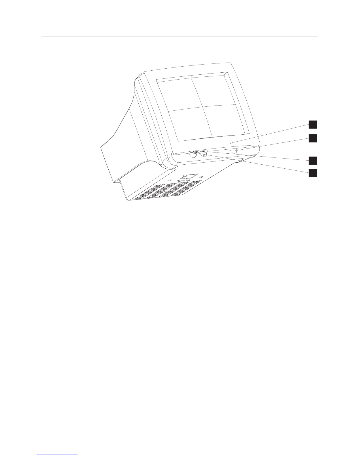
Color LCD Display Controls and Indicators
The color LCD display provides the following controls:
v Power
v Brightness
12 and Figure 13 on page 22 show the controls and connectors locations.
Figure
Operational controls and indicators
A
B
C
Reference Description
A Contrast controls (+ and -)
B Power button
C Power indicator
Figure 12. LCD Indicator locations on the bottom front of the color LCD display
Chapter 3. SurePOS 100 Operations 21
Page 34

Operational controls and indicators
A
Reference Description
A Power control
B + Brightness control
C - Brightness control
D VGA signal port
E Power port
July 27, 2007 - Approval Draft
E
D
C
AB
Video modes
Figure 13. Button and connector locations on the bottom–underside of the color LCD display
Table 5 lists the video modes that you can use.
Table 5. Supported video modes
Mode Resolution fV (Hz) LCD CRT
640 x 350
640 x 400 X X
720 x 350 X
VGA
720 x 400
640 x 480
SVGA 800 x 600
70
70 X
85 X
60 X X
72 X
75 X X
56 X X
60 X X
72 X
75 X
X X
22 4613 SurePOS 100 Point-of-Sale Terminal: Installation and Operation Manual
Page 35

July 27, 2007 - Approval Draft
Adjusting the image
Figure 14 shows how to automatically adjust your display. If you do not obtain the
results that you want with these procedures, use the on-screen display (OSD) menu
and brightness controls that are explained in “Using the OSD menu” on page 24.
Operational controls and indicators
Figure 14. Adjusting the display, pictorial view
Press the plus (+) or the minus (−) button to adjust the brightness. The following
figure shows the information that you see on your display when you modify the
brightness.
Brightness
Figure 15. Brightness Menu
_______________________________________
Adjust
− |_______________________________________| +
Chapter 3. SurePOS 100 Operations 23
Page 36

Operational controls and indicators
As you press the plus or minus button, the menu displays the level of brightness.
When you reach the level that you want, stop pressing the keys. After
approximately five seconds, the brightness menu disappears, and the system saves
your values.
Using the OSD menu
The OSD menu allows you to adjust the display settings such as contrast,
brightness, clock, phase, and image position.
To open the OSD menu, press and hold the minus (−) and plus (+) buttons at the
same time. The following menu appears:
Auto Adjust
Auto Adjust
Automatically adjusts the video settings. Use this option when you install
the display, move the display to another system, or change video mode.
July 27, 2007 - Approval Draft
Manual Adjust
Brightness
Contrast
Information
Reset
______________________________
(+) Select
(-) Scroll
(+&-) Exit
Manual Adjust
Allows you to modify the clock, phase, and image position. Normally, you do
not need to use Manual Adjust because Auto Adjust sets the parameters at
the optimum default value. However, you can use Manual Adjust to fine
tune the display timings.
Brightness
Allows you to modify the display’s brightness setting.
Contrast
Allows you to modify the contrast setting.
Information
Provides the current screen resolution, the horizontal, and the vertical sync
signal frequencies.
Reset Presents a dialog box that allows you to reset the menu settings to the
default values.
Exiting
the OSD Menu: To exit the OSD menu, press the minus (−) and plus (+)
buttons at the same time. The system saves your values.
Restriction: The OSD menu times out after approximately 20 seconds of inactivity.
The system does not save any of your parameters.
24 4613 SurePOS 100 Point-of-Sale Terminal: Installation and Operation Manual
Page 37

July 27, 2007 - Approval Draft
Keylock Operation
The manner in which the keylock positions operate is dependent on the application
program being used by the SurePOS 100. The key can be removed from the
keylock in any of the three positions. The arrow in the center of the keylock points
to the selected position.
Operational controls and indicators
Figure 16. SurePOS 100 Keylock Positions
Operating the Card Reader
1. Align the card with the magnetic stripe facing you, and at the bottom edge of
the card.
2. Place the card in the reader slot to the left or right of the reader, as shown in
Figure 17. The reader is aligned with the card icon below the slot.
3. Pass the card through the reader. Most application programs allow you to pass
the card though the reader in either direction.
Figure 17. Sliding a Card Along a Card Reader
Chapter 3. SurePOS 100 Operations 25
Page 38

Operational controls and indicators
Impact Printer Operating Controls and Indicators
A
C
B
ARibbon Winding Knob
Use this knob to tighten the ribbon around the print head.
July 27, 2007 - Approval Draft
BPrinter Paper Feed and Test Button
Press this button to feed paper through the printer. This button also begins
the printer self-test during printer testing.
CPrinter Ready Indicator
The printer is ready for operation when the indicator is on.
Figure 18. SurePOS 100 Impact Printer - Indicators and Controls
26 4613 SurePOS 100 Point-of-Sale Terminal: Installation and Operation Manual
Page 39

July 27, 2007 - Approval Draft
Loading the Impact Printer Ribbon
1. Press inward on both side tabsBand lift the printer coverAup from the printer
base. The cover swings up on and is connected to the top cover by
hingesCand can be left in the open position.
A
D
Operational controls and indicators
C
B
Figure 19. Opening the Printer Cover
2. Lower the ribbon cartridge into position on the printer.
3. Refer to the following diagram to see how to place the ribbon. Use the ribbon
winding knob to remove any slack in the ribbon.
Correct Not Correct
4. Replace the printer cover by lowering it into its operating position. Be sure that
the side tabs click into place.
Chapter 3. SurePOS 100 Operations 27
Page 40

Operational controls and indicators
Loading the Impact Printer Paper
Follow these steps to load the impact printer paper roll into the SurePOS 100 and
to feed the paper through the printer mechanism.
1. Referring to Figure 19 on page 27, open the printer cover.
2. Referring to Figure 20, place the paper roll into the paper cradle at the back of
the printer housing. The leading edge of the paper should be at the bottom of
the roll and, when pulled from the roll, moves toward the front of the SurePOS
100.
3. Referring to Figure 20, thread the paper through the printer as shown. If the
paper does not feed through the printer automatically when slid into the paper
guide, press the Paper Feed and Test button to advance the paper through the
paper guide path. The button is active only if the SurePOS 100 is powered ON.
July 27, 2007 - Approval Draft
F
Reference Description
A Printer Cover
B Paper Roll
C Paper
D Paper Guide
E Print Head
F Tear Bar Slot
Figure 20. Loading Path for Impact Printer Paper
4. Close (or reinstall) the printer cover. Feed the paper through the slot in the
printer cover while lowering the cover into the closed position.
28 4613 SurePOS 100 Point-of-Sale Terminal: Installation and Operation Manual
A
B
C
E
D
Page 41

July 27, 2007 - Approval Draft
Operational controls and indicators
Thermal Printer Operating Controls and Indicators
A
C
D
B
E
APrinter Mechanism
The printer mechanism pivots upward to clean the print head and to clear
paper jams.
BHead Up Lever
Lifts the print head to clear paper jams.
CPaper Advance Knob
Manually advances paper through the printer.
DPrinter Paper Feed and Test Button
Feeds paper through the printer. This button also begins the printer self-test
during printer testing.
EPrinter Ready Indicator
Indicates when the printer is ready.
Figure 21. SurePOS 100 Thermal Printer - Indicators and Controls
Chapter 3. SurePOS 100 Operations 29
Page 42

Operational controls and indicators
Loading Thermal Printer Paper
1. Referring to Figure 19 on page 27, open the printer cover.
2. Prepare a roll of paper. Make sure that the leading edge of the paper is cut in a
straight right-angle to the direction of the feed.
3. Place the paper roll into the paper roll cradle as shown in Figure 21 on page 29.
The leading edge of the paper should be at the bottom of the roll and, when
pulled from the roll, moves toward the front of the SurePOS 100.
Important: Thermal paper only prints on the smooth (or glossier) side of the
paper. Make sure the smooth side of the paper is facing forward as
it feeds through the printer mechanism.
4. As with the impact printer, the thermal paper should load automatically once the
paper when inserted under the paper guide. The paper can be fed manually
using the Paper Advance Knob. The paper will only feed automatically if the
SurePOS 100 is powered ON.
5. Referring to Figure 22, insert the edge of the paper under the paper guideA.
Continue to insert the paper until the unit automatically advances the paper
through the printer and cutter and the paper is cut. Remove cut paper.
July 27, 2007 - Approval Draft
A
Figure 22. Automatically Loading the Thermal Printer
6. If the paper is not inserted correctly, it will jam. If this happens, complete these
steps:
a. Pull the printer mechanism upward toward you, turn the paper advance knob
until the edge of the paper protrudes from the printer mechanism.
b. Grab the edge of the paper until it is moving straight. After confirming that
six to eight inches of paper is extending from the printer, push the printer
mechanism back to its operating position.
c. 3. Hold the edge of the paper and press it against the head and cut it.
30 4613 SurePOS 100 Point-of-Sale Terminal: Installation and Operation Manual
Page 43

July 27, 2007 - Approval Draft
Close (or reinstall) the printer cover.
7.
Operational controls and indicators
Important: Be careful not to cut your hands or fingers on the edge of the
cutter unit.
Figure 23. Closing and Replacing the Printer Cover
Chapter 3. SurePOS 100 Operations 31
Page 44

Operational controls and indicators
Optional Features Operation
Customer Display Head
Both the optional customer display heads tilt slightly so the image can be displayed
more easily. The display head also rotates left and right approximately 340 degrees.
If you do not use both the long and short customer display posts, the head cannot
rotate as freely because the video display may be in the way.
July 27, 2007 - Approval Draft
Cash Drawer
Figure 24. Adjusting the Customer Display Head
Keylock Positions:
The cash drawer keylock has three positions:
v Locked/Closed
v Operate
v Manual Open/Locked Open
The Operate position permits the cash drawer to open under application
program control. The key is in this position while the SurePOS 100 is in
operation.
In the Locked/Closed position, the drawer cannot be opened. In the Manual
Open/Locked Open position, the drawer remains open and cannot be
closed. The SurePOS 100 will not operate properly when the key is in the
Locked or Locked Open positions.
The key can be removed while in any of the three positions.
32 4613 SurePOS 100 Point-of-Sale Terminal: Installation and Operation Manual
Page 45

July 27, 2007 - Approval Draft
Operational controls and indicators
Locked/
Closed
Operate Manual Open/
Locked Open
Figure 25. Cash Drawer Keylock Positions
Document Storage Area
Space is available under the cash drawer for storing documents. Use the
slot at the front of the cash drawer for depositing documents. An adjustment
barAinside lets you adjust the size of the document storage area to suit
your needs.
A
Figure 26. Cash Drawer Document Storage
Compact Cash Drawer Coin Roll Opener
1. Either push or pull the coin roll against the coin roll opener, as shown in
Figure 27, until a scratch or cut is made in the outside cover of the coin
roll.
2. Break the coin roll open with your hands.
Figure 27. Compact Cash Drawer Coin Roll Opener
Chapter 3. SurePOS 100 Operations 33
Page 46

Operational controls and indicators
July 27, 2007 - Approval Draft
34 4613 SurePOS 100 Point-of-Sale Terminal: Installation and Operation Manual
Page 47

July 27, 2007 - Approval Draft
Chapter 4. Adjusting System Configuration
Configuration Options . . . . . . . . . . . . . . . . . . . . . .35
Configuring the System Unit . . . . . . . . . . . . . . . . . . . .35
Configuration Options
Usually, you do not need to run the system configuration utility because the system
unit configures itself automatically. If there are any memory or port addressing
conflicts, messages displayed during the initial power-on self-test (POST) identify
the conflicts. For details about POST, refer to Chapter 5, “Installation Testing and
Problem Analysis,” on page 37 and the section “Testing Your Installation” on page
37. Enter Setup to correct any configuration problems.
Perform system configuration in the following cases:
v To change any serial port (COM) addresses or interrupt levels
v To start the terminal from a local area network (LAN)
v To change the manner in which the addressing system unit is configured
Configuring the System Unit
To configure your system unit, begin by pressing Delete when prompted during
POST. Many of the values on the Main Menu are set by the program when you
start the SurePOS 100. You can change many of these from the Main Menu, such
as the system date and time. Follow these steps to change system values:
1. Using the arrow keys, select the option that you want to change. Press the
Space bar to change the value. If you want more help, press F1.
2. Press the PgDn key to see the next screen of the configuration menus.
3. Use the next menu to adjust COM port addresses or interrupt levels.
4. Press the PgDn key to see the last screen of Setup.
5. The third screen is the ASIC Options menu. To change the order in which to
look for a start source. Normally, a system checks drive A and then drive C. The
SurePOS 100 also has a third source because it can perform a remote program
load (RPL) from a LAN.
6. Go to Chapter 5, “Installation Testing and Problem Analysis,” on page 37 to test
the SurePOS 100 if you change or adjust any addresses or interrupt levels.
© Copyright IBM Corp. 2007 35
Page 48

Adjusting system configuration
July 27, 2007 - Approval Draft
36 4613 SurePOS 100 Point-of-Sale Terminal: Installation and Operation Manual
Page 49

July 27, 2007 - Approval Draft
Chapter 5. Installation Testing and Problem Analysis
Performing Tests . . . . . . . . . . . . . . . . . . . . . . . .37
Safety Notices . . . . . . . . . . . . . . . . . . . . . . . . .37
Testing Your Installation . . . . . . . . . . . . . . . . . . . . . .37
Problem Analysis . . . . . . . . . . . . . . . . . . . . . . . .39
Preliminary Troubleshooting . . . . . . . . . . . . . . . . . . .39
Problem Analysis Procedure . . . . . . . . . . . . . . . . . . .39
Performing Tests
This chapter describes the process for starting and testing the SurePOS 100. It
begins with the initial self-test the terminal performs at start up, and then begins
problem analysis. To assist with troubleshooting and problem solving, the chapter
contains a list of common problems and their possible solutions.
Safety Notices
DANGER
To avoid a shock hazard, do not connect or disconnect any cables
or perform installation, maintenance, or reconfiguration of this
product during an electrical storm.
DANGER
To avoid shock hazard:
The power cord must be connected to a properly wired and
earthed receptacle.
Any equipment to which this product will be attached must also
be connected to properly wired receptacles.
Testing Your Installation
When you start the SurePOS 100, the system runs its initial diagnostic test, or
POST. If POST does not find any errors, the system is ready for operation.
To begin operations, follows these steps:
1. Connect the power cord from the SurePOS 100 to a properly wired and
grounded power source.
2. Press the System Unit Power buttonAshown in Figure 28 on page 38. Ensure
that the system unit Power IndicatorBis lighted. The self test begins when the
SurePOS 100 power is turned on.
© Copyright IBM Corp. 2007 37
Page 50

Installation testing and problem analysis
Figure 28. Powering On the SurePOS 100
3. Press the Power buttonBon the video display (the VDT display is used here
as an example) and ensure that the display Power IndicatorAis on. For button
locations on the color LCD display, refer toFigure 12 on page 21.
July 27, 2007 - Approval Draft
AB
A
B
4. Follow the instructions on the video display to complete the test. Indications of a
successful completion of POST are:
v The video display is ready for keyboard input
v The Printer Ready indicator is on
v A single, short beep sounds at the completion of POST.
If POST fails or you suspect a problem occurred with your system unit (POST
signals a failure with multiple beeps and error messages), refer to “Problem
Analysis” on page 39.
38 4613 SurePOS 100 Point-of-Sale Terminal: Installation and Operation Manual
Page 51

July 27, 2007 - Approval Draft
Problem Analysis
This chapter contains troubleshooting information to help determine the cause of a
problem and how to solve it.
Preliminary Troubleshooting
If you have a problem with the SurePOS 100, use the following steps to correct the
problem:
1. Make sure that all I/O devices are connected.
2. Make sure that the contrast controls and the brightness controls are adjusted
properly.
3. Make sure that all installed hardware devices (such as a memory module,
feature card, printer, or mouse) are connected properly.
4. After making these checks, power down the SurePOS 100, and restart the unit.
The system runs POST again. Indications of a successful completion of POST
are listed in “Testing Your Installation” on page 37
If the problem still exists after performing these preliminary checks, record any error
messages or symptoms and contact your service technician. If the SurePOS 100 is
not working correctly but you do not receive an error message or observe a
symptom, see Table 6.
Installation testing and problem analysis
Problem Analysis Procedure
If the SurePOS 100 fails, you can use the procedures described in Table 6 to
diagnose and resolve the problem. If you cannot solve the problem, call your
service technician.
Table 6. Troubleshooting Common Problems
If the problem is... Here is what to do...
The system power indicator at the terminal shows that it
is OFF.
The power LED is amber on the color LCD display.
The terminal is not working.
v Ensure that the power cord is plugged into both the
wall outlet and the back of the terminal.
v Ensure that the system unit is on.
v Ensure that there is power from the outlet.
v Low-power mode. Communication is not yet
established between host and monitor display.
v Ensure that the video cable connections are working
correctly, and replace the cables, if necessary.
v Verify that the unit is started.
v Check the standby or suspend mode of power
management.
v Replace the system unit, if necessary.
v Power down the SurePOS 100, and then power ON
the SurePOS 100.
v Ensure there is not a tripped circuit breaker or an
outlet power failure.
v Ensure that all cables are securely connected to the
terminal.
Chapter 5. Installation Testing and Problem Analysis 39
Page 52

Installation testing and problem analysis
Table 6. Troubleshooting Common Problems (continued)
If the problem is... Here is what to do...
No image is displayed on display or display.
The color LCD displays an unsupported video mode
message.
The color LCD display displays No Video/low power
mode message.
The color LCD display has an unacceptable image
quality.
The keyboard does not work or only some keys work.
There is an (I/O) error.
v Ensure that the power indicator for the display shows
that it is ON. If not, go to the "The terminal is not
working" instructions.
v Ensure that the system unit is on.
v Ensure that the brightness controls are set correctly.
v If the LED is amber (on the color LCD display only), go
to ″The power LED amber on the color LCD display.″
v Check the cable connections.
v Call service technician.
Change to a supported mode. See Table 5 on page 22.
Communication is not yet established between the host
unit and the color LCD display. Ensure that the system
unit is on. Ensure that the video cabling between the
color LCD display and the system unit is working
correctly.
1. Activate the Auto-Adjust setting by pressing and
holding both the plus (+) and minus (-) brightness
controls to show the OSD menu. Then Press the plus
(+) button to adjust the brightness, and then press
and hold both buttons after the brightness has been
adjusted to exit the menu.
2. If using the Auto-Adjust option does not resolve the
problem, show the OSD menu, and then, press the
minus (-) button to select to the Manual Adjust option,
and then press the plus (+) button to select it.
3. Select the Manual Adjust setting by pressing the
minus (-) button, and then the plus (+) button.
4. Activate the Phase option by pressing the plus (+)
button. Adjust the phase by pressing the plus (+) and
minus (-) buttons until you obtain the best display
image.
5. To manually adjust the Clock, Horizontal and
Vertical, repeat Step 3, and then select your option
by pressing the minus (-) button. Then activate it by
pressing the plus (+) button. Adjust the setting by
pressing the plus (+) and minus (-) buttons until you
obtain the best display image.
6. Ensure that the video mode is set to 800 x 600 (if the
application can run in this mode.)
7. Check the video cable connections, and replace the
cables, if necessary.
v Move your fingers across the keys. Make sure no keys
are stuck.
v Power down the SurePOS 100, and then restart the
unit.
v Ensure that the I/O device is connected correctly to the
system unit.
July 27, 2007 - Approval Draft
40 4613 SurePOS 100 Point-of-Sale Terminal: Installation and Operation Manual
Page 53

July 27, 2007 - Approval Draft
Installation testing and problem analysis
Table 6. Troubleshooting Common Problems (continued)
If the problem is... Here is what to do...
There is a blank screen, no cursor is displayed, screen is
unreadable, or other display problems.
v Ensure that the terminal and display cables are
securely connected.
v Ensure that the terminal and display are ON.
v Ensure that the power indicator lights are ON.
v Adjust the contrast and brightness controls on the
display.
Paper jams (impact printer).
v Ensure that paper can pass through the paper path
without crimping.
v Remove loose paper from the mechanism of the paper
path.
Paper jams (thermal printer)
v Remove loose paper from the mechanism of the paper
path. If the jam cannot be removed, pull the printer
mechanism upward and turn the feed knob to remove
the paper. After you remove the paper, push the printer
mechanism back into place.
The thermal paper advance is not responding.
v Ensure that the printer mechanism is pushed down into
operating position.
The integrated printer is not working.
v Run POST by pressing and holding the paper feed
button while powering on the system. The printer prints
out the self-test pattern. If this test fails, call for service.
v For externally attached printers, refer to the
manufacturer's publications.
Notes:
1. Some devices that attach to the system have test instructions. Refer to those
instructions when testing those devices.
2. When using application software, you might receive error messages that pertain
to the software. Refer to the application software manual for a description of
those messages.
Chapter 5. Installation Testing and Problem Analysis 41
Page 54

July 27, 2007 - Approval Draft
42 4613 SurePOS 100 Point-of-Sale Terminal: Installation and Operation Manual
Page 55

July 27, 2007 - Approval Draft
Appendix A. Service diagnostics, device drivers, and
diagnostic information
The following procedure list the steps on how to download a version of the 4613
Service Diagnostics image:
1. Go to http://www.ibm.com/solutions/retail/store
2. Select Support.
3. Select IBM SurePOS 100 System.
4. Scroll down to 4613 Service Diagnostics. Click the version of diagnostics to
download and save to a directory.
POS Device Tests
A test is provided for each of the POS devices such as:
v Display
v Cash drawer
v Customer display
v Keyboard
v MSR
v Keylock
v Impact Printer
v Thermal Printer
See “Printer Test Patterns” on page 44 for more information. The printer tests
Note:
apply only to the integrated printer. Externally attached printers must be
tested using routines supplied by the printer manufacturer.
System Utility Tests
A test is provided for each of the system unit devices such as:
v CPU sub-system
v System memory
v Mouse port
v Serial RS-232 ports
v VGA sub-system (video display)
v Parallel port (PC Printer)
v Fixed disk drive
v LAN adapter
Viewing Configuration
You can view configuration selections by selecting ″View Configuration″ from the
Main Menu.
© Copyright IBM Corp. 2007 43
Page 56

Service diskette, device drivers, and diagnostic information
Printer Test Patterns
Figure 29 shows the correct print outputs for the printer test.
Inverted Line Mode Underline Mode Overline Mode
Figure 29. Printer Test Patterns
July 27, 2007 - Approval Draft
44 4613 SurePOS 100 Point-of-Sale Terminal: Installation and Operation Manual
Page 57

July 27, 2007 - Approval Draft
Appendix B. System Cleaning Information
Prior to cleaning any of the SurePOS 100 parts or components, make sure to
power down the system and unplug all power cables from electrical outlets.
Customer User Product Care Procedures
Owners and users periodically should inspect their system unit and its components
for cleanliness and perform the following procedures based on usage and
environmental characteristics.
System Unit
1. Vacuum the ventilation grills on the front and right side of the base unit. The
right-side vent provides cooling for the power supply while the front vent
provides cooling for the rest of the unit components.
2. Clean the plastic covers with a cloth moistened with water.
3. When greater cleaning is required, use a cloth moistened with warm water and
a small amount of mild, abrasive-free hand soap, or a dish washing detergent
used for washing dishes by hand. After cleaning, use a cloth moistened with
water to remove the soap residue.
4. When extensive cleaning is required, use a cloth moistened with a solution of
rubbing alcohol (isopropyl alcohol) and water.
5. Make sure the unit is dry prior to powering the unit back on.
Do not apply the cleaning solution directly to the product. Always apply or
Note:
spray the cleaner on a clean cloth and then wipe the surface of the
product.
Monochrome
Display and Color LCD Display
Follow these guidelines:
1. Use a soft, dry cloth with rubbing alcohol on any non-abrasive, non-alkaline,
non-ammonia based cleaner.
2. Wipe gently across the surface.
3. Allow a few minutes for the surface to dry before using.
Do not apply cleaning solution directly to the screen. Always apply or
Note:
spray the cleaner on a clean cloth and then wipe the screen.
Keyboard
1. Vacuum the keyboard.
2. Wipe the keyboard cover and the keycaps with a cloth moistened with water.
3. Make sure the keyboard is dry prior to powering the unit back ON.
Do not apply cleaning solution directly to the cover or keys. Always apply
Note:
or spray the cleaner on a clean cloth and then wipe the cover and
keycaps.
© Copyright IBM Corp. 2007 45
Page 58

System cleaning information
Service Provider System Maintenance Procedures
System Unit and Cash Drawer
Inspect the cables and power cord for chafing, frayed insulation, cracks, or breaks.
Replace any cables or power cords that appear to be faulty.
Keyboard and MSR
Pass the cleaning card (P/N 6019483) through the MSR a few times.
Keylocks
Apply three drops of silicon lubricant (P/N 96X4791) into the key opening of the
system unit and cash drawer keylocks.
Printer
1. Clean any dust, fuzz balls, debris, or chad from the printer.
2. For the thermal printer, clean the platen and printhead with a cloth moistened
with rubbing alcohol if needed.
3. Make sure the printer is dry prior to powering the unit back ON.
July 27, 2007 - Approval Draft
46 4613 SurePOS 100 Point-of-Sale Terminal: Installation and Operation Manual
Page 59

July 27, 2007 - Approval Draft
Appendix C. Printer Supplies
Listed below are some of the supplies required for operation of the SurePOS 100
printers.
Impact Printer Supplies
Many paper types are available. Please use paper that meets the following
specifications:
MP500 Printer
Paper Width 76 mm (3.00 in.)
Paper Rolls Internal diameter: 11 to 13 mm (0.43 to 0.51 in.)
Outer diameter: 82 mm (3.23 in.) maximum
Ribbon Star RC200P or Equivalent
Thermal Printer Supplies
Use general high-sensitivity thermal paper that can be ordered locally. Many paper
types are available. Please use paper that meets the following specifications:
Paper Type General high-sensitivity thermal paper
Paper Width 79 to 80 mm (3.11 to 3.15 in.)
Paper Thickness General thermal paper: 67µm
Paper Rolls Internal diameter: 11 to 13 mm (0.43 to 0.51 in.)
Outer diameter: 82 mm (3.23 in.) maximum
© Copyright IBM Corp. 2007 47
Page 60

Printer supplies
July 27, 2007 - Approval Draft
48 4613 SurePOS 100 Point-of-Sale Terminal: Installation and Operation Manual
Page 61

July 27, 2007 - Approval Draft
Appendix D. Safety information
Danger:
Before you begin to install this product, read the safety information in IBM
Safety Information — Read This First, GA27-4004. This booklet describes safe
procedures for cabling and plugging in electrical equipment.
Gevaar:
Voordat u begint met de installatie van dit produkt, moet u eerst de
veiligheidsinstructies lezen in de brochure Veiligheidsinstructies—Lees dit
eerst, GA27-4004. Hierin wordt beschreven hoe u electrische apparatuur op
een veilige manier moet bekabelen en aansluiten.
Perigo:
Antes de começar a instalar este produto, leia as informações de segurança
contidas em Informações Sobre Seguranaça—Leia Isto Primeiro, GA27-4004.
Esse folheto descreve procedimentos de segurança para a instalação de
cabos e conexões em equipamentos elétricos.
Fare!
Før du installerer dette produkt, skal du læse sikkerhedsforskrifterne i
Sikkerhedsforskrifter—Lœs dette først GA27-4004. Vejledningen beskriver den
fremgangsmåde, du skal bruge ved tilslutning af kabler og udstyr.
© Copyright IBM Corp. 2007 49
Page 62
July 27, 2007 - Approval Draft
Gevaar
Voordat u begint met het installeren van dit produkt, dient u eerst de
veiligheidsrichtlijnen te lezen die zijn vermeld in de publikatie IBM Safety
Information — Read This First, GA27-4004. In dit boekje vindt u veilige
procedures voor het aansluiten van elektrische appratuur.
VAARA
Ennen kuin aloitat tämän tuotteen asennuksen, lue julkaisussa
Turvaohjeet—Luetämä ensin, GA27-4004, olevat turvaohjeet. Tässä kirjasessa
on ohjeet siitä, miten sähkölaitteet kaapeloidaan ja kytketään turvallisesti.
Danger
Avant d’installer le présent produit, consultez le livret Informations pour la
sécurité–Lisez-moi d’abord, GA27-4004, qui décrit les procédures à respecter
pour effectuer les opérations de câblage et brancher les équipements
électriques en toute sécurité.
Vorsicht
Bevor mit der Installation des Produktes begonnen wird, die
Sicherheitshinweise in Sicherheitsinformationen—Bitte zuerst lesen, IBM Form
GA27-4004. Diese Veröffentlichung beschreibt die Sicherheitsvorkehrungen für
das Verkabeln und Anschlieβen elektrischer Geräte.
50 4613 SurePOS 100 Point-of-Sale Terminal: Installation and Operation Manual
Page 63

July 27, 2007 - Approval Draft
Mielôtt megkezdi a berendezés üzembe helyezését, olvassa el a IBM Safety
Information — Read This First, GA27-4004 könyvecskében leírt biztonsági
információkat. Ez a könyv leírja, milyen biztonsági intézkedéseket kell
megtenni az elektromos berendezés huzalozásakor illetve csatlakoztatásakor.
prima di iniziare l’installazione di questo prodotto, leggere le informazioni
relative alla sicurezza riportate nell’opuscolo Informazioni di sicurezza—Prime
informazioni da leggere in cui sono descritte le procedure per il cablaggio ed il
collegamento di apparecchiature elettriche.
Vigyázat
Pericolo
Fare
Før du begynner å installere dette produktet, må du lese
sikkerhetsinformasjonen i Sikkerhetsinformasjon—Les dette først, GA27-4004
som beskriver sikkerhetsrutinene for kabling og tilkobling av elektrisk utstyr.
Perigo
Antes de iniciar a instalação deste produto, leia as informações de segurança
Informações de Segurança—Leia Primeiro, GA27-4004. Este documento
descreve como efectuar, de um modo seguro, as ligações eléctricas dos
equipamentos.
Appendix D. Safety information 51
Page 64

July 27, 2007 - Approval Draft
Peligro
Antes de empezar a instalar este producto, lea la información de seguridad en
Información de Seguridad—Lea Esto Primero, GA27-4004. Este documento
describe los procedimientos de sequridad para cablear y enchufar equipos
eléctricos.
Varning—livsfara
Innan du börjar installera den här produkten bör du läsa
säkerhetsinformationen i dikumentet Säkerhetsföreskrifter—Läs detta först,
GA27-4004. Där beskrivs hur du på ett säkert sätt ansluter elektrisk utrustning.
52 4613 SurePOS 100 Point-of-Sale Terminal: Installation and Operation Manual
Page 65

July 27, 2007 - Approval Draft
IBM
IBM
GA27-4004
GA27-4004
Appendix D. Safety information 53
Page 66

GA27-4004
July 27, 2007 - Approval Draft
IBM
GA27-4004
GA27-4004
GA27-4004
GA27-4004
54 4613 SurePOS 100 Point-of-Sale Terminal: Installation and Operation Manual
GA27-4004
Page 67

July 27, 2007 - Approval Draft
Appendix E. Notices
This information was developed for products and services offered in the U.S.A.
IBM may not offer the products, services, or features discussed in this document in
other countries. Consult your local IBM representative for information on the
products and services currently available in your area. Any reference to an IBM
product, program, or service is not intended to state or imply that only that IBM
product, program, or service may be used. Any functionally equivalent product,
program, or service that does not infringe any IBM intellectual property right may be
used instead. However, it is the user’s responsibility to evaluate and verify the
operation of any non-IBM product, program, or service.
IBM may have patents or pending patent applications covering the subject matter in
this document. The furnishing of this document does not give you any license to
these patents. You can send license inquiries, in writing, to:
Director of Licensing
IBM
IBM Corporation
North Castle Drive
Armonk, NY 10504-1785
U.S.A.
license inquiries regarding double-byte character set (DBCS) information,
For
contact the IBM Intellectual Property Department in your country or send inquiries,
in writing, to:
World Trade Asia Corporation
IBM
Licensing
2-31 Roppongi 3-chome, Minato-ku
Tokyo 106, Japan
following paragraph does not apply to the United Kingdom or any other country
The
where such provisions are inconsistent with local law: INTERNATIONAL BUSINESS
MACHINES CORPORATION PROVIDES THIS PUBLICATION "AS IS" WITHOUT
WARRANTY OF ANY KIND, EITHER EXPRESS OR IMPLIED, INCLUDING, BUT
NOT LIMITED TO, THE IMPLIED WARRANTIES OF NON-INFRINGEMENT,
MERCHANTABILITY, OR FITNESS FOR A PARTICULAR PURPOSE. Some states
do not allow disclaimer of express or implied warranties in certain transactions,
therefore, this statement may not apply to you.
This information could include technical inaccuracies or typographical errors.
Changes are periodically made to the information herein; these changes will be
incorporated in new editions of the publication. IBM may make improvements and/or
changes in the product(s) and/or program(s) described in this publication at any
time without notice.
IBM may use or distribute any of the information you supply in any way it believes
appropriate without incurring any obligation to you.
Any references in this information to non-IBM Web sites are provided for
convenience only and do not in any manner serve as an endorsement of those
Web sites. The materials at those Web sites are not part of the materials for this
IBM product and use of those Web sites is at your own risk.
© Copyright IBM Corp. 2007 55
Page 68

July 27, 2007 - Approval Draft
Information concerning non-IBM products was obtained from the suppliers of those
products, their published announcements or other publicly available sources. IBM
has not tested those products and cannot confirm the accuracy of performance,
compatibility or any other claims related to non-IBM products. Questions on the
capabilities of non-IBM products should be addressed to the suppliers of those
products.
This information is for planning purposes only. The information herein is subject to
change before the products described become available.
56 4613 SurePOS 100 Point-of-Sale Terminal: Installation and Operation Manual
Page 69

July 27, 2007 - Approval Draft
Electronic emission notices
Federal Communications Commission (FCC) statement
This equipment has been tested and found to comply with the limits for a Class A
digital device, pursuant to Part 15 of the FCC Rules. These limits are designed to
provide reasonable protection against harmful interference when the equipment is
operated in a commercial environment. This equipment generates, uses, and can
radiate radio frequency energy and, if not installed and used in accordance with the
instruction manual, may cause harmful interference to radio communications.
Operation of this equipment in a residential area is likely to cause harmful
interference, in which case the user will be required to correct the interference at
his own expense.
Properly shielded and grounded cables and connectors must be used in order to
meet FCC emission limits. IBM is not responsible for any radio or television
interference caused by using other than recommended cables and connectors or by
unauthorized changes or modifications to this equipment. Unauthorized changes or
modifications could void the user’s authority to operate the equipment.
This device complies with part 15 of the FCC Rules. Operation is subject to the
following two conditions:
1. This device may not cause harmful interference, and
2. This device must accept any interference received, including interference that
may cause undesired operation.
European Union EMC Directive conformance statement
This product is in conformity with the protection requirements of EU Council
Directive 2004/108/EC on the approximation of the laws of the Member States
relating to electromagnetic compatibility. IBM cannot accept responsibility for any
failure to satisfy the protection requirements resulting from a non-recommended
modification of the product, including the fitting of non-IBM option cards.
This product has been tested and found to comply with the limits for Class A
Information Technology Equipment according to CISPR 22/European Standard EN
55022. The limits for Class A equipment were derived for commercial and industrial
environments to provide reasonable protection against iinterferencewith licensed
communication equipment.
Attention: This is a Class A product. In a domestic environment this product may
cause radio interference in which case the user may be required to take adequate
measures.
European Community contact:
Technical Regulations
IBM
Pascalstr. 100, Stuttgart, Germany 70569
Telephone: 0049 (0)711 785 1176
Fax: 0049 785 1283
E-mail: tjahn@de.ibm.com
Appendix E. Notices 57
Page 70

July 27, 2007 - Approval Draft
Industry Canada Class A Emission Compliance statement
This Class A digital apparatus complies with Canadian ICES-003.
Avis de conformité aux normes d’Industrie Canada
Cet appareil numérique de la classe A est conforme à la norme NMB-003 du
Canada.
Germany
Zulassungsbescheinigung laut dem Deutschen Gesetz über die
elektromagnetische Verträglichkeit von Geräten (EMVG) vom 30. August 1995
(bzw. der EMC EG Richlinie 89/336).
Dieses Gerät ist berechtigt in Übereinstimmung mit dem Deutschen EMVG das
EG-Konformitätszeichen - CE - zu führen.
Verantwortlich für die Konformitätserklärung nach Paragraph 5 des EMVG ist die
IBM Deutschland Informationssysteme GmbH, 70548 Stuttgart
Informationen
Das Gerät erfüllt die Schutzanforderungen nach EN 50082–1 und EN 55022 Klasse A.
in Hinsicht EMVG Paragraph 3 Abs. (2) 2:
EN 55022 Klasse A Geräte müssen mit folgendem Warnhinweis versehen werden:
″Warnung: dies ist eine Einrichtung der Klasse A. Diese Einrichtung kann im
Wohnbereich Funkstörungen verursachen; in diesem Fall kann vom Betreiber
verlangt werden, angemessene Maβnahmen durchzuführen und dafür
aufzukommen.″
EN 50082–1 Hinweis:
″Wird dieses Gerät in einer industriellen Umgebung betrieben (wie in EN 50082–2
festgelegt), dann kann es dabei eventuell gestört werden. In solch einem Fall ist der
Abstand bzw. die Abschirmung zu der industriellen Störquelle zu vergröβern.″
Anmerkung:
Um die Einhaltung des EMVG sicherzustellen sind die Geräte, wie in den IBM
Handbüchern angegeben, zu installieren und zu betreiben.
Australia and New Zealand
Attention: This is a Class A product. In a domestic environment this product may
cause radio interference, in which case the user may be required to take adequate
measures.
58 4613 SurePOS 100 Point-of-Sale Terminal: Installation and Operation Manual
Page 71

July 27, 2007 - Approval Draft
Chinese Class A warning statement
Attention: This is a Class A product. In a domestic environment this product may
cause radio interference in which case the user may be required to take adequate
measures.
Japanese power line harmonics compliance statement
Japanese Voluntary Control Council for Interference (VCCI) statement
Attention: This product is a Class A Information Technology Equipment and
conforms to the standards set by the Voluntary Control Council for Interference by
Technology Equipment (VCCI). In a domestic environment this product may cause
radio interference in which case the user may be required to take adequate
measures.
Korean communications statement
Please note that this device has been approved for business purposes with regard
to electromagnetic interference. If you find this is not suitable for your use, you may
exchange it for a non-business purpose one.
Appendix E. Notices 59
Page 72
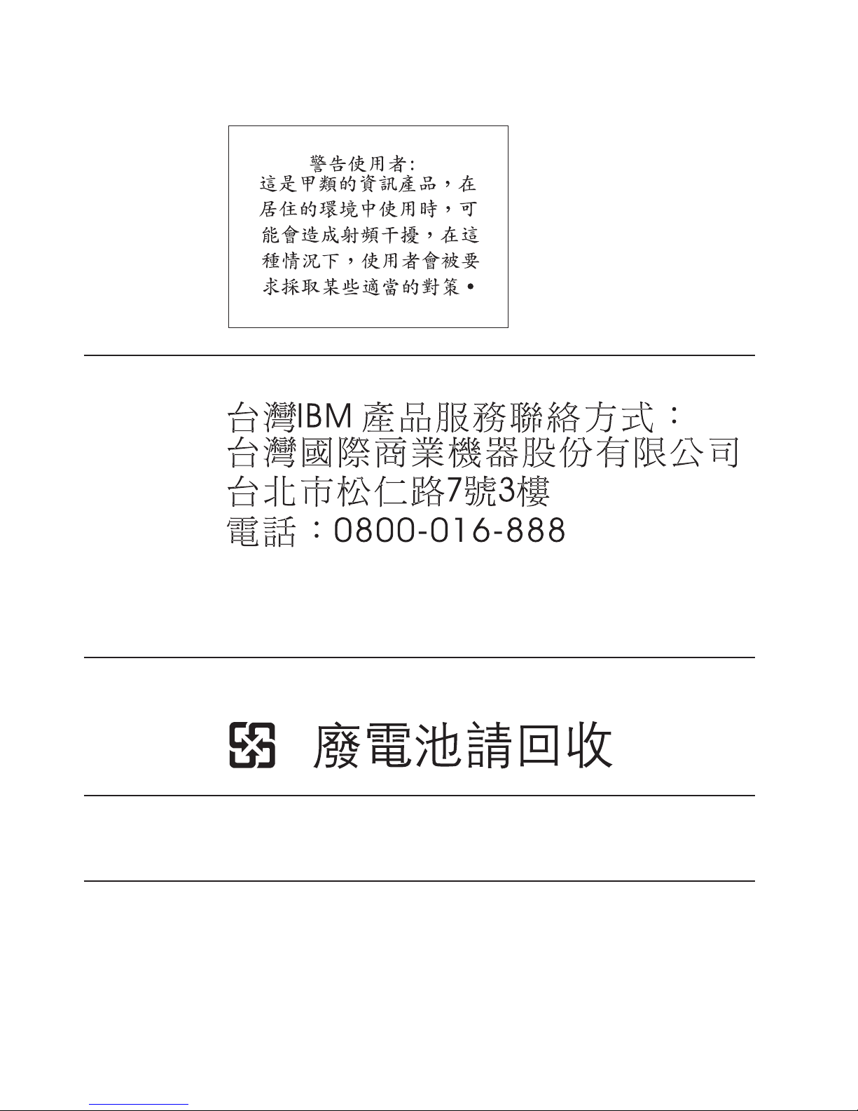
Taiwanese Class A warning statement
Taiwan contact information
July 27, 2007 - Approval Draft
IBM Taiwan Product Service Contact Info:
IBM Taiwan Corporation
3F, No 7, Song Ren Road, Taipei Taiwan
Telephone: 0800-016-888
Taiwanese battery recycling statement
Waste batteries, please recycle.
Cable ferrite requirement
All cable ferrites are required to suppress radiated EMI emissions and must not be
removed.
Electrostatic Discharge (ESD)
Attention: ESD damage can occur when there is a difference in charge between
the part, the product, and the service person. No damage will occur if the service
person and the part being installed are at the same charge level.
60 4613 SurePOS 100 Point-of-Sale Terminal: Installation and Operation Manual
Page 73

July 27, 2007 - Approval Draft
ESD Damage Prevention
Anytime a service action involves physical contact with logic cards, modules,
back-panel pins, or other ESD sensitive (ESDS) parts, the service person must be
connected to an ESD common ground point on the product through the ESD wrist
strap and cord.
The ESD ground clip can be attached to any frame ground, ground braid, green
wire ground, or the round ground prong on the AC power plug. Coax or connector
outside shells can also be used.
Handling Removed Cards
Logic cards removed from a product should be placed in ESD protective containers.
No other object should be allowed inside the ESD container with the logic card.
Attach tags or reports that must accompany the card to the outside of the container.
End of life disposal
This unit must be recycled or discarded according to applicable local and national
regulations. IBM encourages owners of information technology (IT) equipment to
responsibly recycle their equipment when it is no longer needed. IBM offers a
variety of product return programs and services in several countries to assist
equipment owners in recycling their IT products. Information on IBM product
recycling offerings can be found on IBM’s Internet site at http://www.ibm.com/ibm/
environment/products/prp.shtml.
Notice: This mark applies only to countries within the European Union (EU) and
Norway.
Appliances are labeled in accordance with European Directive 2002/96/EC
concerning waste electrical and electronic equipment (WEEE). The Directive
determines the framework for the return and recycling of used appliances as
applicable throughout the European Union. This label is applied to various products
to indicate that the product is not to be thrown away, but rather reclaimed upon end
of life per this Directive.
In accordance with the European WEEE Directive, electrical and electronic
equipment (EEE) is to be collected separately and to be reused, recycled, or
recovered at end of life. Users of EEE with the WEEE marking per Annex IV of the
WEEE Directive, as shown above, must not dispose of end of life EEE as unsorted
municipal waste, but use the collection framework available to customers for the
return, recycling, and recovery of WEEE. Customer participation is important to
minimize any potential effects of EEE on the environment and human health due to
the potential presence of hazardous substances in EEE. For proper collection and
treatment, contact your local IBM representative.
Disposal of IT products should be in accordance with local ordinances and
regulations.
Appendix E. Notices 61
Page 74

Trademarks
July 27, 2007 - Approval Draft
The following are trademarks of International Business Machines Corporation in the
United States or other countries, or both:
IBM and the IBM logo
PS/2
SureMark
SurePoint
SurePOS
Wake on LAN
Microsoft, Windows, Windows NT, and the Windows logo are trademarks of
Microsoft Corporation in the United States, other countries, or both.
Celeron and Intel are trademarks of Intel corporation in the United States, or other
countries.
Java and all Java-based trademarks and logos are trademarks or registered
trademarks of Sun Microsystems, Inc. in the United States, or other countries, or
both.
Other company, product, or service names may be trademarks or service marks of
others.
62 4613 SurePOS 100 Point-of-Sale Terminal: Installation and Operation Manual
Page 75

July 27, 2007 - Approval Draft
Index
Numerics
4613 1
model specifications 2
port connector locations 7
power requirements 3
system unit cable 7
A
accessibility of publications x
accessories 47
adjusting
brightness
controls 24
audience
readers
ix
auto adjust menu item 24
B
brightness
controls,
adjusting 24
menu item 24
brightness controls 23
brightness menu 23
C
cable ferrite requirement 60
cables
installation
card reader, operation 25
cash drawer operations 32
checklist preliminary 39
checklist, problem determination 39
Class A compliance statement
Australia
China 59
European Union 57
FCC (USA) 57
Germany 58
Industry Canada 58
Japan 59
Taiwan 60
communications cable, installation 12
configuration, system 35
configurations, viewing 43
contrast menu item 24
controls 17
color LCD display 21
monochrome video display 19
system unit 18
controls, brightness 23
customer display
installation
customer display operations 32
customer tower 13
12
and New Zealand 58
13
customizing
base
unit 10
D
damage from electrostatic discharge 60
display image, adjusting the 23
disposal of equipment 61
downloading the service diagnostic 43
E
electronic emissions notices 57
Australia and New Zealand 58
China 59
European Union 57
FCC (USA) 57
Germany 58
Industry Canada 58
Japan 59
Korea 59
Taiwan 60
electrostatic discharge (ESD) 60
end of life disposal 61
equipment disposal 61
exiting
the
OSD menu 24
through time-out 24
F
features
keyboard
13
optional 6
customer display 13
standard 4
features, optional 32
ferrite requirement 60
I
I/O cables, installation 12
image, adjusting the display 23
impact printer
paper
loading 28
indicators 17
Information menu item 24
installation
begin
9
communications cable 12
customer display 13
I/O cables 12
keyboard legends 13
power cord 12
power-on self-test 37
problem determination 39
quad key 16
© Copyright IBM Corp. 2007 63
Page 76

July 27, 2007 - Approval Draft
installation (continued)
ribbon
cartridge 12
testing 37
unpacking 9
installing
riser
card 16
J
Japanese power line harmonics compliance
statement 59
Japanese Voluntary Control Council for Interference
statement 59
K
keyboard legends
configuring
13
keylock operation 25
Korean communications statement 59
L
library, 4613 SurePOS 100 ix
loading paper
impact
printer 28
thermal printer 30
M
maintenance procedures, system 46
manual adjust menu item 24
menu, exiting the OSD 24
messages 39
MSR operation 25
N
notices 49, 55
battery recycling 60
cable ferrites 60
electronic emissions 57
electrostatic discharge (ESD) 60
end of life disposal 61
IBM 55
OSD menu (continued)
exiting
24
information 24
manual adjust 24
reset 24
using 24
overview 1
P
paper loading
impact
printer 28
thermal printer 30
power consumption 3
Preliminary Checklist 39
printer
paper
loading, impact 28
paper loading, thermal 30
removing or replacing
supplies
47
ribbon loading 27
printer, impact operating controls and indicators 26
printer, thermal operating controls and indicators 29
problem analysis 39
Problem Analysis 39
problem determination 39
downloading the service diagnostic 43
messages 39
POS device tests 43
printer test patterns 44
symptoms 39
system utility tests 43
viewing configurations 43
product 1
model specifications 2
port connector locations 7
system unit cable 7
product care procedures 45
publications
overview
ix
related ix
Q
quad key
installation
16
O
operating control 17
operating controls, impact printer 26
operation 25
card reader 25
MSR 25
optional features 6
customer display, installation 13
organized, book ix
OSD menu
auto
adjust 24
brightness 24
contrast 24
64 4613 SurePOS 100 Point-of-Sale Terminal: Installation and Operation Manual
R
Reset menu item 24
ribbon cartridge installation 12
ribbon loading 27
riser card, installing 16
S
safety information 49
service diagnostic, downloading 43
service provider procedure, maintenance 46
setup 9
Page 77

July 27, 2007 - Approval Draft
software, related ix
standard features 4
store system library ix
supplies 47
symptoms 39
system cleaning information 45
system configuration 35
T
Taiwanese battery recycling statement 60
testing
messages
symptoms 39
testing 37
tests
POS
printer patterns 44
system utility 43
thermal printer
paper
time-out, exiting through 24
trademarks 61
trouble shooting 39
troubleshooting 39
39
device 43
loading 30
U
unpacking 9
upgrade 10
V
viewing configurations 43
Index 65
Page 78

July 27, 2007 - Approval Draft
66 4613 SurePOS 100 Point-of-Sale Terminal: Installation and Operation Manual
Page 79

Readers’ Comments — We’d Like to Hear from You
4613 SurePOS 100 Point-of-Sale Terminal
Installation and Operation Manual
Publication No. GA27-4368-00
We appreciate your comments about this publication. Please comment on specific errors or omissions, accuracy,
organization, subject matter, or completeness of this book. The comments you send should pertain to only the
information in this manual or product and the way in which the information is presented.
For technical questions and information about products and prices, please contact your IBM branch office, your IBM
business partner, or your authorized remarketer.
When you send comments to IBM, you grant IBM a nonexclusive right to use or distribute your comments in any
way it believes appropriate without incurring any obligation to you. IBM or any other organizations will only use the
personal information that you supply to contact you about the issues that you state on this form.
Comments:
Thank you for your support.
Submit your comments using one of these channels:
v Send your comments to the address on the reverse side of this form.
If you would like a response from IBM, please fill in the following information:
Name
Company or Organization
Phone No. E-mail address
Address
Page 80

___________________________________________________________________________________________________
Readers’ Comments — We’d Like to Hear from You
GA27-4368-00
Fold
_________________________________________________________________________________________
and Tape Please do not staple Fold and Tape
NO
POSTAGE
NECESSARY
MAILED IN THE
IF
UNITED STATES
Cut or Fold
Line
Along
BUSINESS REPLY MAIL
FIRST-CLASS MAIL PERMIT NO. 40 ARMONK, NEW YORK
POSTAGE WILL BE PAID BY ADDRESSEE
IBM Corporation
Retail Store Solutions Information Development, Dept ZBDA
P. O. Box 12195
RESEARCH TRIANGLE PARK NC 27709-9990
_________________________________________________________________________________________
and Tape Please do not staple Fold and Tape
Fold
GA27-4368-00
or Fold
Cut
Along Line
Page 81

Page 82

July 27, 2007 - Approval Draft
GA27-4368-00
 Loading...