

Page 1

SurePOS 100 Technical Reference
SurePOS 100
IBM 4613 Point of Sale Terminal
Technical Reference
Version 1.0
Dec 31, 2007
Please note that all of the features, functions, etc. defined in this document are subject to change
without notice. Not all models, features, etc. are announced in all countries, and references in this
document are not an indication that IBM will support these items in the future in every country. Consult
with your IBM sales professional for assistance in identifying what is available in your country.
(c) Copyright International Business Machines Corporation 2001. All rights reserved.
Page 1 of 104
Page 2

SurePOS 100 Technical Reference
Change History
Version Date Change Description
1.0 Initial Release
Page 2 of 104
Page 3

SurePOS 100 Technical Reference
Table of Contents
1.0 Introduction................................................................................................................................................... 5
1.1 Overview....................................................................................................................................................... 5
1.2 Related Documents...................................................................................................................................... 6
2.0 The SurePOS 100 Mechanical Package...................................................................................................... 8
2.1 Dimensions................................................................................................................................................... 8
2.2 Controls & Indicators .................................................................................................................................... 8
2.2.1 Special Tools for Service ..................................................................................................................... 9
3.0 Comparison with SureOne ......................................................................................................................... 10
3.1.1 Device Comparison with SureOne..................................................................................................... 10
4.0 SurePOS 100 Technical Specs and Programming Information................................................................. 12
5.0 SurePOS 100 System Unit Technical Information ..................................................................................... 13
5.1 Processor Specifications ............................................................................................................................ 13
5.2 System Memory.......................................................................................................................................... 13
5.3 Video........................................................................................................................................................... 13
5.4 Ethernet ...................................................................................................................................................... 13
5.5 Hard File ..................................................................................................................................................... 13
5.6 PCI Expansion Slot..................................................................................................................................... 14
5.7 I/O Ports...................................................................................................................................................... 14
5.7.1 Connectors/ Pinouts........................................................................................................................... 15
5.7.2 Serial Port Pinouts ............................................................................................................................. 15
6.0 Device Hardware Specifications................................................................................................................. 16
6.1 Keyboard, Keylock, MSR............................................................................................................................ 16
6.1.1 Keyboard............................................................................................................................................ 16
6.1.2 Keylock............................................................................................................................................... 17
6.1.3 Magnetic Stripe Reader (MSR).......................................................................................................... 17
6.1.4 Multiple Input considerations ............................................................................................................. 18
6.2 Monitor........................................................................................................................................................ 19
6.2.1 Monochrome CRT monitor – Model 108............................................................................................ 19
6.2.2 Color LCD monitor – Model 118 ........................................................................................................ 19
6.2.3 Supported Video Modes .................................................................................................................... 19
6.3 Optional 2x20 VFD Customer Display........................................................................................................ 19
6.4 Optional 1x11 LED 7-segment display ....................................................................................................... 20
6.5 Printer ......................................................................................................................................................... 21
6.5.1 Impact Printer..................................................................................................................................... 21
6.5.2 Thermal Printer .................................................................................................................................. 22
7.0 System Programming Considerations........................................................................................................ 24
7.1 Identification via software ........................................................................................................................... 24
7.2 Control Registers........................................................................................................................................ 24
7.2.1 Definitions: ......................................................................................................................................... 24
7.3 Memory Map............................................................................................................................................... 26
8.0 IO Programming Considerations ................................................................................................................ 27
8.1 Keyboard .................................................................................................................................................... 27
8.2 Keyboard/ MSR BIOS Command protocol................................................................................................. 27
8.3 JAVAPOS Keyboard/MSR Command protocol.......................................................................................... 29
8.4 Magnetic Strip Reader (MSR) .................................................................................................................... 30
8.4.1 MSR Error Handling........................................................................................................................... 30
8.5 Keylock ....................................................................................................................................................... 30
9.0 Printer Programming .................................................................................................................................. 31
9.1 Impact Printer ............................................................................................................................................. 31
9.2 Thermal Printer........................................................................................................................................... 31
9.3 Communications......................................................................................................................................... 31
9.3.1 DTR Mode.......................................................................................................................................... 31
9.3.2 XON/XOFF Mode............................................................................................................................... 33
Page 3 of 104
Page 4

9.3.3
STX-ETX Mode.................................................................................................................................. 34
9.3.4 Star Mode Commands....................................................................................................................... 36
9.3.5 Control Codes Used for Line Spacing ............................................................................................... 43
9.3.6 Control Codes Used for Page Layout................................................................................................ 45
9.3.7 Control Codes Used for Graphics Printing......................................................................................... 48
9.3.8 Control Codes Used for Character Downloading .............................................................................. 49
9.3.9 Cash Drawer Commands................................................................................................................... 52
9.3.10 Other Control Codes .......................................................................................................................... 53
9.3.11 Control Codes .................................................................................................................................... 57
9.3.12 ESC/POS Mode Commands.............................................................................................................. 65
9.4 Cash Drawer............................................................................................................................................... 67
Appendix A Quick Reference for Printer Commands ....................................................................................... 69
9.5 Printer Command Reference -- Standard Version ..................................................................................... 69
9.5.1 General Usage Commands -- Standard Version............................................................................... 69
9.5.2 IBM Extended Commands -- Standard Version................................................................................. 72
9.6 Printer Command Reference -- Simplified and Traditional Chinese Versions ........................................... 72
9.6.1 Control Codes -- Simplified and Traditional Chinese Versions.......................................................... 72
9.6.2 DBCS Character Commands -- Simplified and Traditional Chinese Versions .................................. 74
9.6.3 IBM Extended Commands -- Simplified and Traditional Chinese Versions ...................................... 75
Appendix B Adapter Cable Definition – 15 Pin to standard 9 pin ..................................................................... 76
10.0 Customer Display Programming Information ............................................................................................. 77
10.1 1x11 LED Display................................................................................................................................... 77
10.1.1 1x11 Command Set ........................................................................................................................... 77
10.1.2 1x11 Character Set............................................................................................................................ 77
10.2 2x20 VFD Customer Display .................................................................................................................. 77
10.2.1 Command Set .................................................................................................................................... 77
11.0 Appendix - Code Pages.............................................................................................................................. 84
11.1.1 Code Page 00850 (Multilingual) ........................................................................................................ 85
11.1.2 Code Page 00852 (Eastern Europe) ................................................................................................. 86
11.1.3 Code Page 00855 (Bulgaria) ............................................................................................................. 87
11.1.4 Code Page 00857 (Turkey)................................................................................................................ 88
11.1.5 Code Page 00862 (Israel).................................................................................................................. 89
11.1.6 Code Page 00864 (Arabic) ................................................................................................................ 90
11.1.7 Code Page 00866 (Russia)................................................................................................................ 91
11.1.8 Code Page 00869 (Greece)............................................................................................................... 92
11.1.9 Code Page 00874 (Thailand) (Printer Only) ...................................................................................... 93
11.1.10 Code Page 00897 (Japan) ............................................................................................................ 94
12.0 PC DOS 7.0 Reference Publications.......................................................................................................... 95
13.0 Keyboard Programming Utility Guide ......................................................................................................... 98
13.1 Requirements ......................................................................................................................................... 98
13.2 Utility Functions ...................................................................................................................................... 98
13.3 Procedures ............................................................................................................................................. 99
13.4 Programming Limitations ..................................................................................................................... 104
SurePOS 100 Technical Reference
Page 4 of 104
Page 5

SurePOS 100 Technical Reference
1.0 Introduction
1.1 Overview
The SurePOS 100 Point of Sale Terminal-- theIBM 4613--is an integrated terminal solution comprised of a
motherboard, keyboard, MSR, receipt printer, monitor, keylock, and networking capability in a single mechanical
package. Attachment of optional cash drawers and customer displays is supported. SurePOS 100 is the
successor to the IBM SureOne (4614).
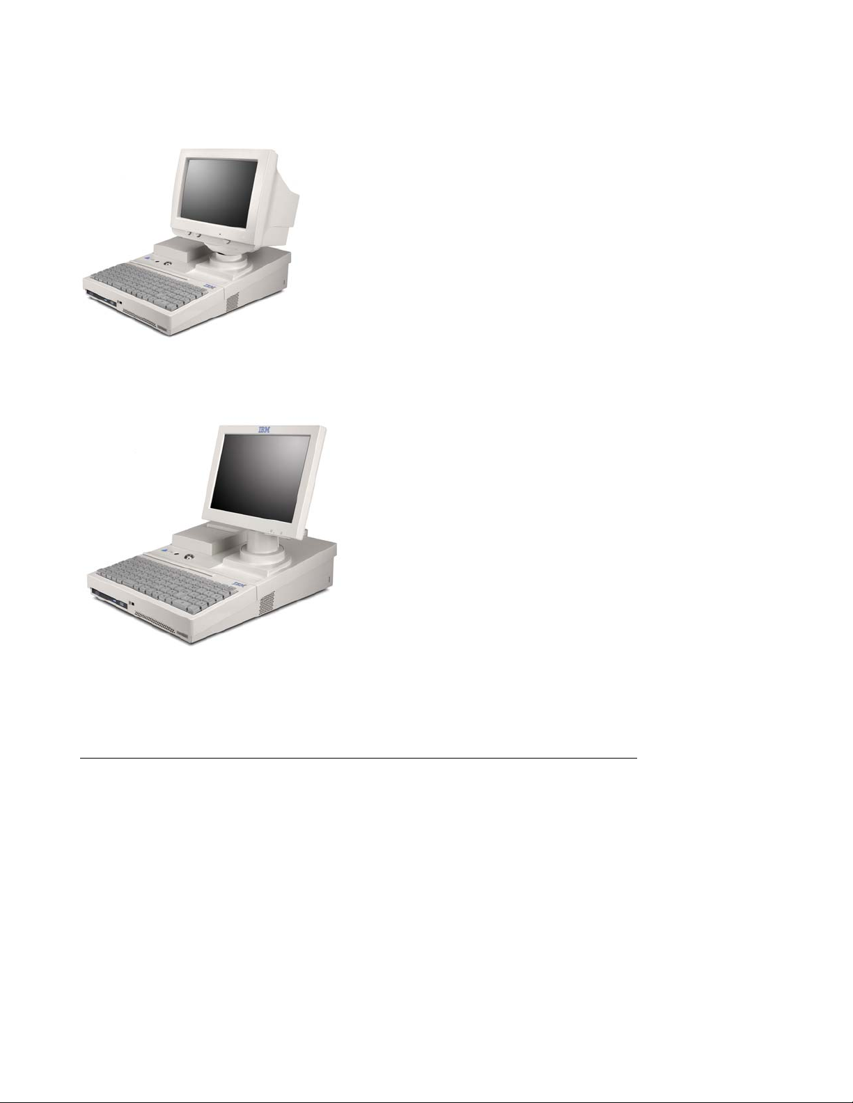
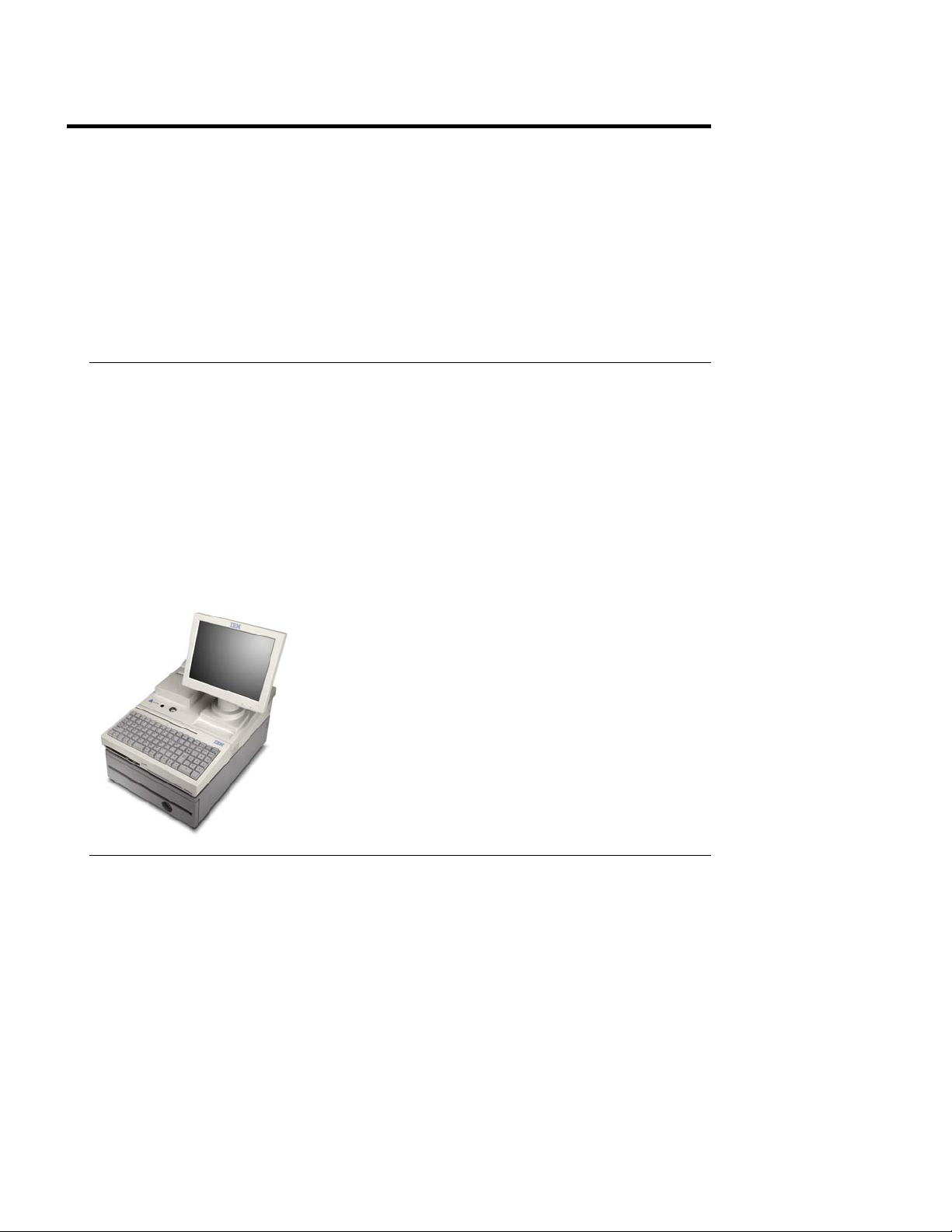
There are two 4613 models.
The 4613-108 incorporates a 9 inch monochrome SVGA CRT monitor.
The 4613- 118 incorporates a 10 inch SVGA LCD monitor.
All SurePOS 100 models include the following components and features:
• Via C7 CPU and Chipset
• 256M system memory standard, with slot available for upgrade
• 96-key keyboard with customizable keys and keytop accessory kits
• 3-track MSR
• CD-ROM (optional feature)
• 80 GB or larger fixed disk drive
• 10/100 Ethernet port
• One partial length PCI feature card slot (optional feature)
• External I/O ports:
o 24V Cash Drawer that drives OEM and IBM 24V cash drawers
o 4x RS232, 2 of them IBM 15-pin Powered RS232
o 2x USB
o additional 1X front USB port
o one 12V Powered USB port
o PS2 Keyboard and Mouse
o Ethernet
o VGA
• A single-station impact or thermal printer, with DBCS support options for Simplified and Traditional
Chinese. A machine may be ordered without a printer installed.
• 2 x 20 Vacuum Flourescent customer display (optional feature)
• 1x11 7-segment LED customer display (optional feature)
• Compact and full-size optional cash drawers (optional featurss)
• OS Support
o PC DOS 7
o Windows 2000/XP
Page 5 of 104
Page 6
SurePOS 100 Technical Reference
Figure 1. Model 108
Figure 2. Model 118
1.2 Related Documents
SurePOS 100 Product Documents
1. IBM SurePOS 100 Point-of-Sale Terminal Installation and Operation Manual, GA27-4368
2. IBM SurePOS 100 Point-of-Sale Terminal Hardware Service Guide, GY27-0425
Page 6 of 104
Page 7

3. IBM SurePOS 100 Operating System Installation Guide
4. IBM SurePOS 100 Getting Started Guide
SurePOS 100 Technical Reference
Page 7 of 104
Page 8
SurePOS 100 Technical Reference
2.0 The SurePOS 100 Mechanical Package
The chassis and component integration features are designed with cost, ease of service, and ruggedness in mind.
The following components are integrated into the chassis:
- Core logic; CPU, system board, etc.
- Monitor
- Printer
- Keyboard
- MSR
- Keylock
- Power Supply
- Mounting point for optional Customer Display.
2.1 Dimensions
System unit height at front: 5.2 cm (2.05 in)
System unit height at rear: 12 cm (4.72 in)
Height of monitor : 37 cm (14.6 in)
System unit width 33 cm (13 in)
Weight:
Model 108 (CRT) 12.6 kg (27.8 lbs)
Model 118 (LCD) 10.6 kg (23.5 lbs)
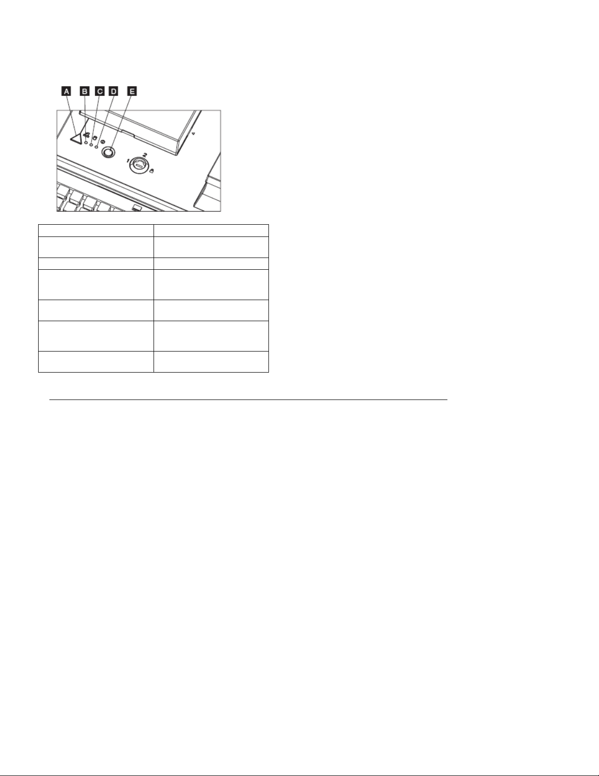
The width and depth dimension allow the unit to sit atop an IBM small footprint cash drawer. The feet of the unit
must be placed in a manor such that they integrate into the top of the cash drawer and effectively “lock” the two
components together when moved in the horizontal plane.
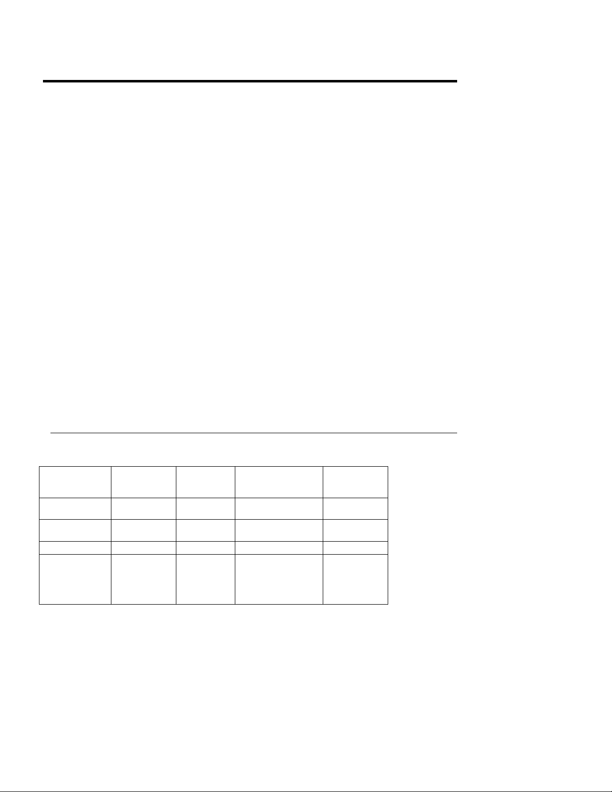
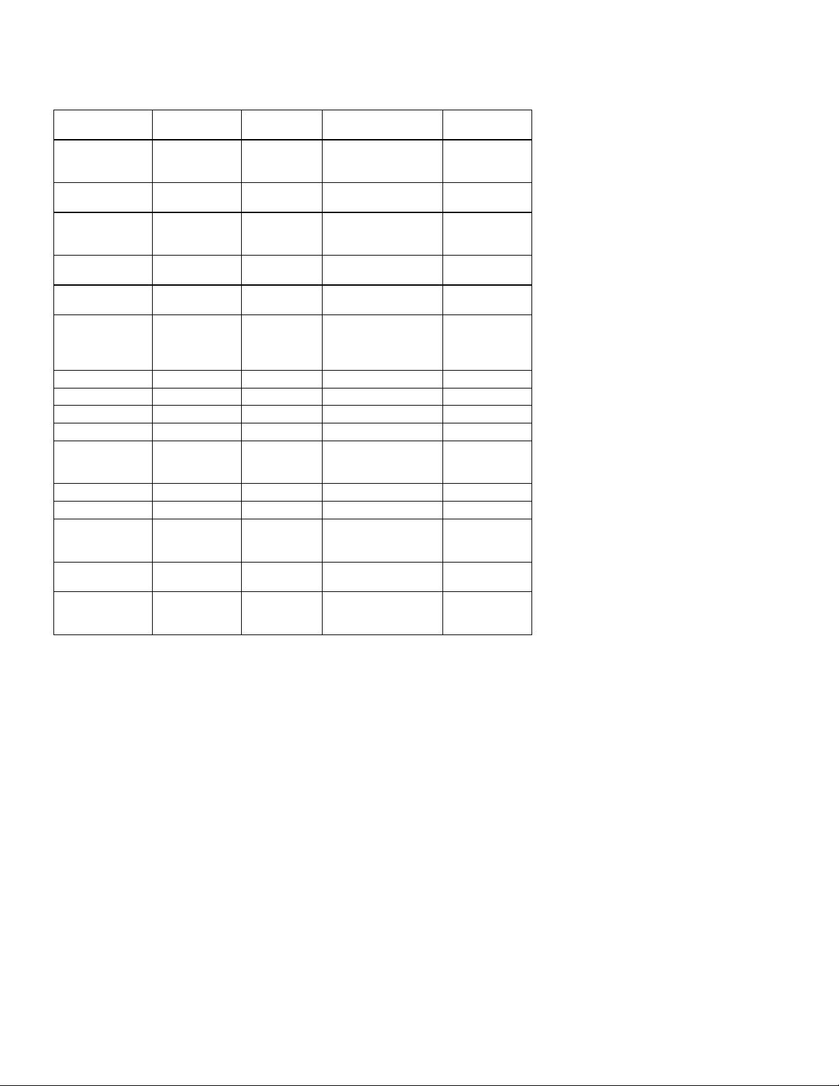
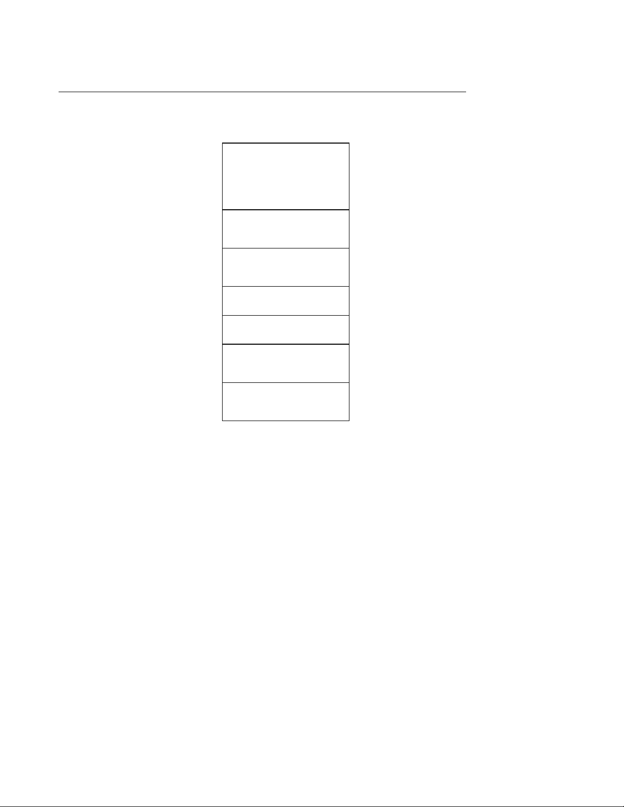
2.2 Controls & Indicators
All system unit controls and indicators are located at the control panel on top of the SurePOS 100.
Page 8 of 104
Page 9
SurePOS 100 Technical Reference
Control or Indicator Location
Paper feed button
Printer Status B
Green hard drive activity
indicator
Green power-on indicator
Power-on and power-off
switch
3-position keylock to the right of the power
A
C
D
E
button E
2.2.1 Special Tools for Service
To maintain the SurePOS 100 terminals, the service representative may need the following items that are not
supplied in the tool kit:
• Keytop puller, P/N 38H6011 or P/N 63X5175
• Lock cylinder alignment key, lock installation-removal key, and dummy lock insert key, P/N 4783922
• MSR test card, P/N 90X9640
• 9-pin loop-back test connector for serial ports, PN 38H6039
• 15-pin loop-back test connector for serial ports, PN 38H6035
Page 9 of 104
Page 10
SurePOS 100 Technical Reference
3.0 Comparison with SureOne
The SurePOS 100 Point of Sale Terminal is an electrical and mechanical redesign of the 4614 SureOne P80/P81.
The following information is intended to assist SureOne users with the transition to the SurePOS 100.
Most external I/O devices and programming interfaces are compatible between the two products.
Exceptions are noted below.
SurePOS 100 does not:
• support a journal take up kit.
• enable fiscalization. A SurePOS 100-based fiscal solution uses the printerless model with a locally
sourced fiscal printer.
• Offer a Floppy disk drive.
• Offer a Parallel port
• Have a printer cover open sensor.
SurePOS 100 uses a standard IBM RSS RS-232 2x20 VFD option—the SureONE VFD is not compatible.
The SureOne VFD is not electrically compatible with SurePOS 100. There is no available port.
The programming interface of the standard 2x20 used with SurePOS 100 is similar in many respects to the
SureOne interface. Key areas of difference are in selection of code pages and in establishing User-defined
characters.
SurePOS 100 supports a 3 track MSR.
MSR error reporting is improved. See the SurePOS 100 Keyboard Tech Ref.
Minor differences in MSR scan codes exist between SurePOS 100 and SureONE. See the SurePOS 100
Keyboard Tech Ref.
The SurePOS100 keyboard uses the same key-switch technology as IBM’s Point of Sale Keyboard line.
This section contains a list of the devices that constitute each functional section of each model. Detailed device
specifications are found in subsequent sections.
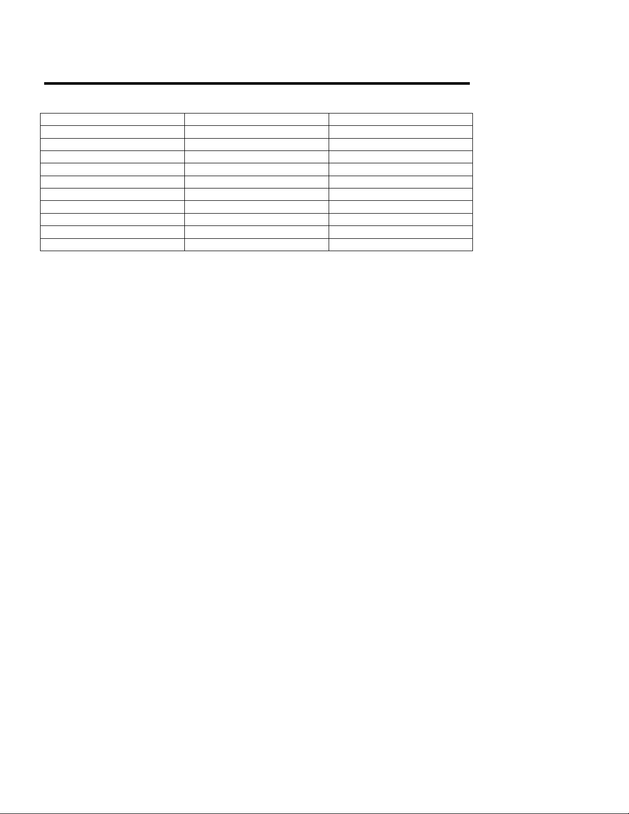
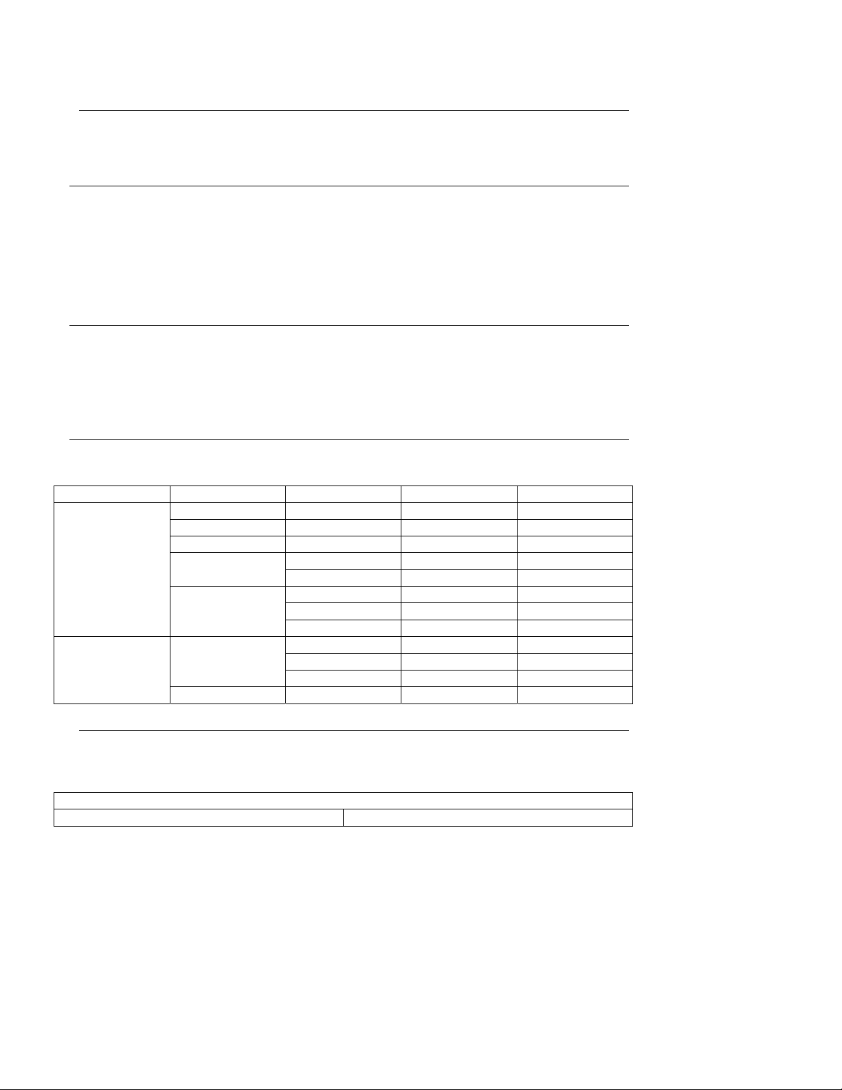
3.1.1 Device Comparison with SureOne
Subsystem SurePOS 100
Processor
Core Logic
Chipset
Video Controller Via Via Different OEM Driver
System Memory
Page 10 of 104
Via C7
2.0GHz
Via CN700,
VT8237R+
DDR2
256MB–1GB
(2G tested but
not presently
offered)
SureOne
4614P80/P81
Via C3
866Mhz
Via VT8602
VT686B
SDRAM
64MB512MB
Driver Impact App Impact
Different OEM Driver
Different OEM Driver
∅ ∅
∅
∅
∅
Page 11
HDD Interface
(see CD Rom)
LED customer
display
VFD Port
Integrated 96key
programmable
PS/2 Keyboard
Ethernet Via MAC
Integrated PS/2
MSR wedge
Printer Support
Dot Matrix
Thermal
USB Ports, 2x USB 2.0 USB 1.1
Front USB USB 2.0 none
Powered USB 12v Port none
RS232 Ports 2 Powered 1 Powered
PCI Slot
CRT Port 15 pin analog 15 pin analog
Display Power 12v 12v
Cash Drawer
Power Supply autoranging
Keylock
SureOne Product Documents
1. IBM 4614 SureOne Point of Sale Technical Reference Information
2. IBM 4614 SureOne Point of Sale Technical Reference Addendum
3. IBM 4614 SureOne Point-of-Sale Terminal: Quick Reference, GA27-4135
4. IBM 4614 SureOne Point-of-Sale Terminal: Hardware Service Manual, GY27-0353
5. IBM 4614 SureOne Point-of-Sale Terminal: Service Diskette, SX27-4012.
6. IBM SureOne Programmable Keyboard Technical Reference
SATA
connection
15pin Powered
RS232
15pin Powered
RS232
Custom
Keyboard
XAC
XAC XAC
Star MP512II
Star TMP212
32 bit/33Mhz
1 partial length
24v
240h/241h
interface
3 position
240h/241h
interface
SurePOS 100 Technical Reference
IDE
connection
none
IBM Port 4
RS232
SMK
Keyboard
Nat. Semi.
MAC
Star MP512II
Star TMP212
32bit/33Mhz
1partial
length
24v
240h/241/
interface
hi/lo voltage
switch
3 position
240h/241h
interface
∅ ∅
no UPOS driver
support- direct IO via
RS-232
∅ ∅
new UPOS driver as
required
Different OEM Driver
new UPOS driver as
required
∅ ∅
∅ ∅
∅ ∅
∅ ∅
∅ ∅
∅ ∅
∅ ∅
∅ ∅
∅ ∅
∅
∅
∅
Page 11 of 104
Page 12
SurePOS 100 Technical Reference
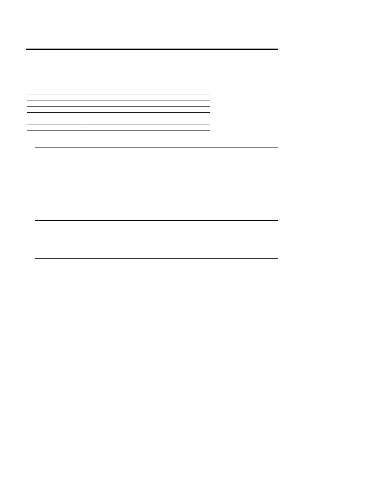
4.0 SurePOS 100 Technical Specs and Programming Information
Technical Specs Programming Information
System Unit Section 5.0 on page 13 Section 7.0 on page 24
Keyboard Section 6.1 on page 16 Section 8.1 on page 27
Keylock Section 6.1 on page 16 Section 8.5 on page 30
MSR Section 6.1 on page 16 Section on page
Impact Printer Section 6.5.1 on page 21 Section 9.0 on page 31
Thermal Printer Section 6.5.2 on page 22 Section 9.0 on page 31
Monitor Section 6.2 on page 19 n/a
CD-DVD Section 6.2 on page 19 n/a
2x20 LCD Section 6.3on page 19 Section 10.2 on page 77
1x11 LED Section 6.4 on page 20 Section 10.1 on page 77
Page 12 of 104
Page 13
SurePOS 100 Technical Reference
5.0 SurePOS 100 System Unit Technical Information
5.1 Processor Specifications
Via C7D
Function
Frequencies 2.0Ghz
Socket None
Cache Two 64KB 4-way L1 Caches
FSB 800Mhz
5.2 System Memory
533MHz DDR2 DIMMS.
Supported Memory configurations:
Base 256M, Expansion 0M
Base 512M, Expansion 0M
Base 256M, Expansion 512M as a field feature
Base 512M, Expansion 512M as a field feature
128KB L2 Cache
5.3 Video
Video function is provided by the integrated CPU chipset for all models. The video subsystem uses System
Memory for video storage. The BIOS Setup utility allows the user to allocate a portion of System memory for the
video frame buffer. Video memory of 16MB, 32MB and 64MB can be allocated.
5.4 Ethernet
. NO SUPPORT FOR RPL OR NETWARE PROTOCOLS is provided.
Depending on software and BIOS setup options, if a unit is off and AC power is available, the LAN function WakeOn-LAN can be enabled. This feature can be used to cause a terminal that is in either the standby or off state to
“wake up” or power up on a specified LAN event. Waking up from the off state is dependent on the OS used, the
level of support provided by the LAN drivers, and how the customer has configured the hardware, OS, and
application.
The LAN function is compatible with the following industry standards:
IEEE 802.3i 10baseT/100baseT physical layer interface
IEEE 802.3u auto negotiation
5.5 Hard File
Page 13 of 104
Page 14
One SATA port is provided at 1.5 Gb/s.
SurePOS 100 Technical Reference
5.6 PCI Expansion Slot
One internal, partial length, 32 bit/ 33 MHz PCI Expansion Slot is provided for use with industry standard
expansion cards. Typical PCI cards used in retail are Modems and NVRAM adapters (e.g. Atlas card).
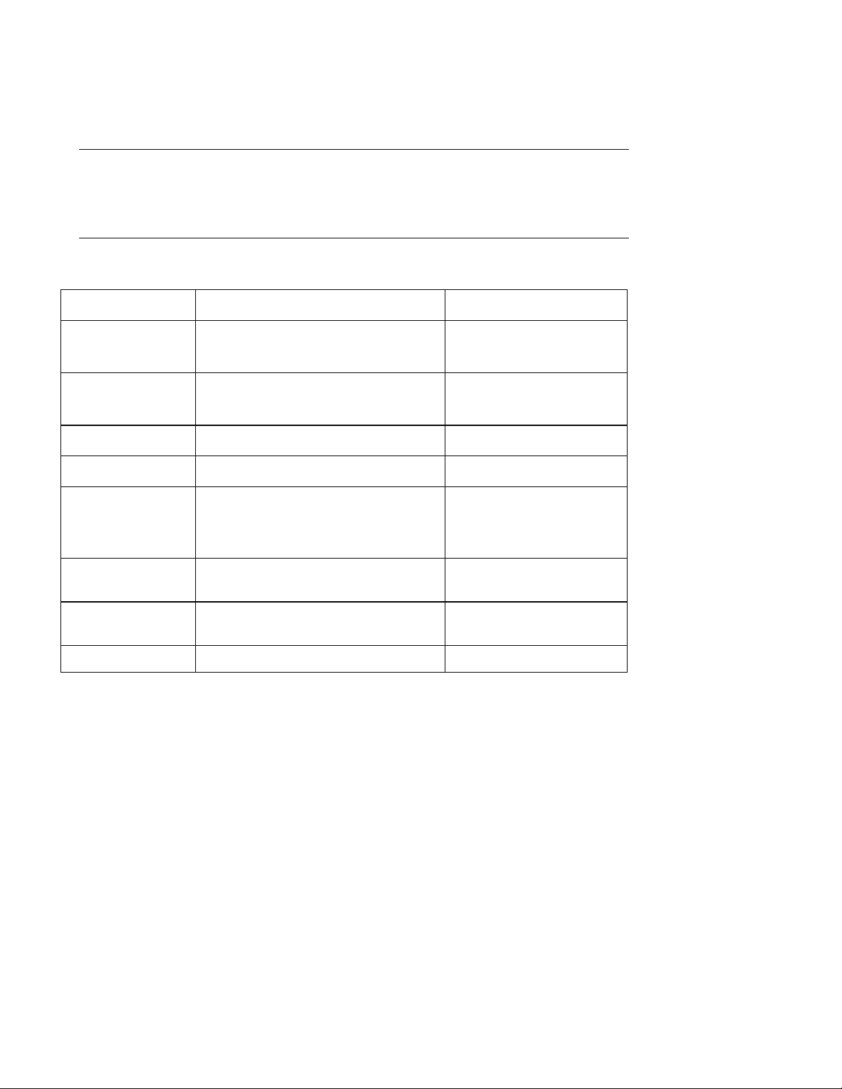
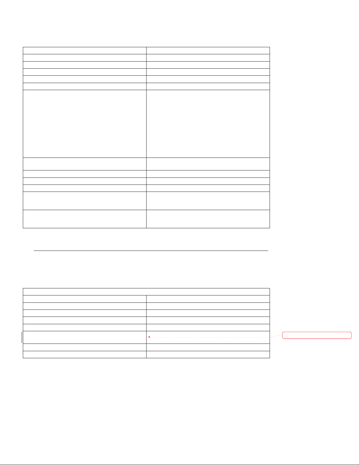
5.7 I/O Ports
Port Description
RS232 Serial Two 9 pin D-shell,
USB One 12V Powered USB
CRT Video
Keyboard/Mouse
Ethernet RJ-45 connector with integrated
Two 15pin D-shell Powered, 5v and 12v
16550 UART Compatible
One Standard USB 2.0, Front
Two Standard USB 2.0, Rear
All speeds supported: High, Full, Low
Industry standard 15 pin D-shell Analog RGB
video port
PS/2 interface, two separate ports, one
keyboard one mouse
Green Link and Amber Activity LEDs
Auto-negotiation of 10Mbit and 100Mbit
Hot Plug Support
No
Yes
No
No
Yes
Cash Drawer One IBM 24V cash drawer port Yes
DC Power Port Dedicated DC power for the LCD display option No
PCI Slot
Page 14 of 104
Internal partial length PCI 32bit/33Mhz slot
The PCI riser card is an optional feature.
No
Page 15
SurePOS 100 Technical Reference
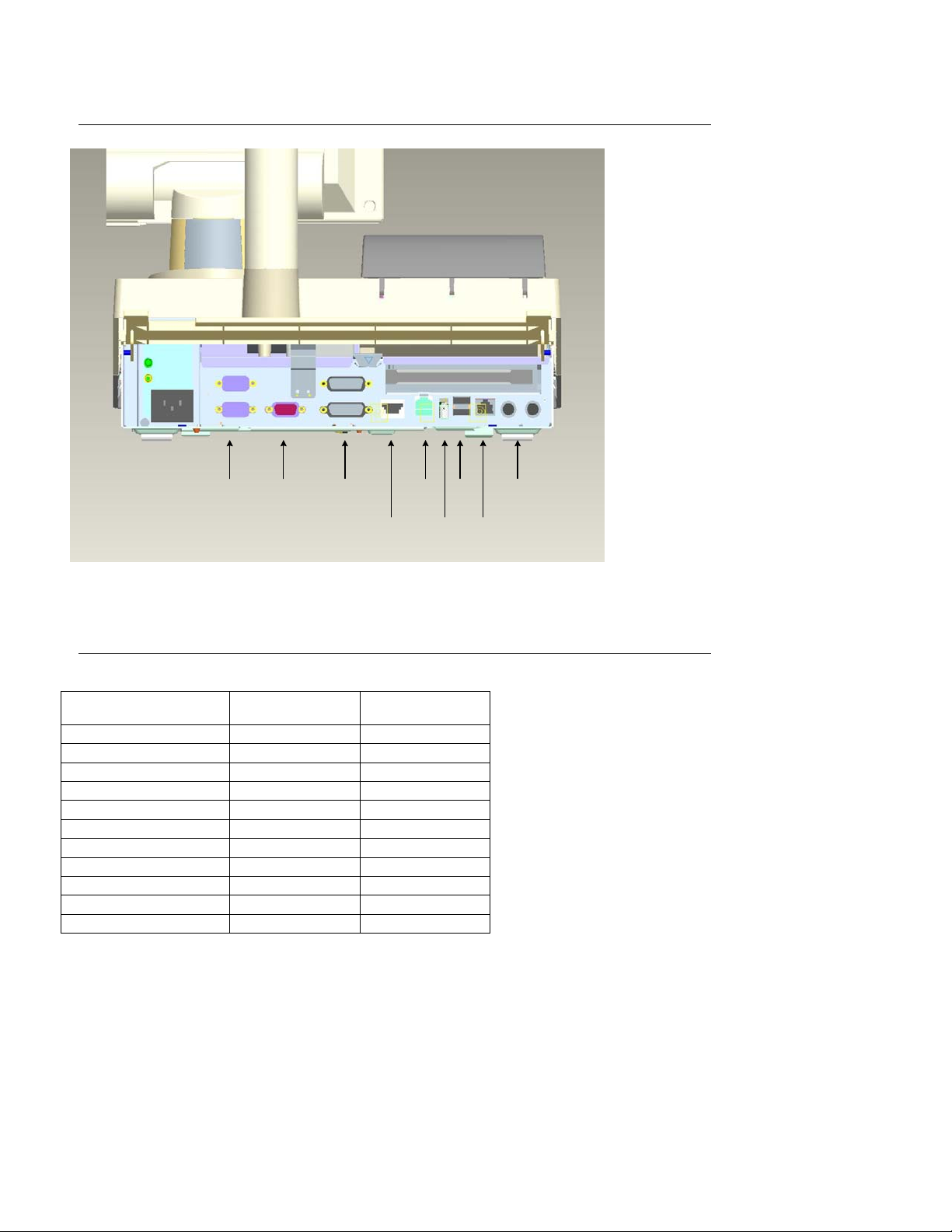
5.7.1 Connectors/ Pinouts
Cash
Drawer
USB
12 V
PCI
LCD
power
USB
(2X)
Ethernet
Keyboard,
Mouse
AC
(2X)
VGA RS-232
Powered
RS-232
(2X)
Figure 3. SurePOS 100 I/O Ports
5.7.2 Serial Port Pinouts
Signal Description
Port A,B (standard)
9 pin D shell
CD 1 1
RXD 2 2
TXD 3 3
DTR 4 4
DSR 6 12
RTS 7 13
CTS 8 14
RI 9 15
GND 5 5,6,11
+5V (+5%, -10% at conn.) n/a 7,10
+12V (+5%. -10% at conn.) n/a 8,9
Page 15 of 104
Port C,D (powered)
15 pin D shell
Page 16
SurePOS 100 Technical Reference
6.0 Device Hardware Specifications
6.1 Keyboard, Keylock, MSR
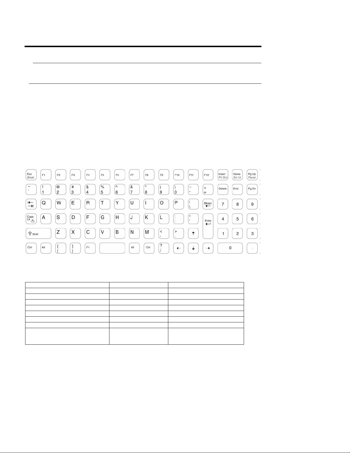
6.1.1 Keyboard
The SurePOS 100 terminal has a matrix keyboard with the following features:
96 keys
The standard accessory kit contains the clear keycaps, plus double keys and blanking bars.
The keyboard is shipped without keycaps installed. The distributor merges a language- or country-unique keytop
or keytop label kit with the unit.
An optional accessory kit provides a quad key
Default QWERTY style that is layout compatible with a Standard PC 101, 102, or 103 key layout
The keyboard appears to the system as a standard PC keyboard. The capability to program the keyboard scan
codes which are transmitted to the application software is described in the SurePOS 100 Programmable
Keyboard Technical Reference section of this document.
Figure 4. US English SurePOS 100 Keyboard (101 Layout)
Keyboard Specifications
Item Specification Notes
Key Switch Technology Membrane
Number of Keys 96 keys 6 rows, 16 columns
Travel, Full 4.0 – 0.4 mm
Travel, Pre 2.0 +/-0.6mm
Key pressure 60 +/-20cN Parallel to key centerline
Key bounce time < 5 mS
Programmable scan codes per key 255
Spill Resistance Membrane Immersion in
water for up to 30
minutes
Page 16 of 104
Page 17
Lens Cap Removal Force 500 grams minimum
Key Cap Nomenclature Preprinted key labels
SurePOS 100 Technical Reference
6.1.1.1 Keyboard/MSR Controller IC
Item Specification Notes
Upstream Host Interface PS/2 Keyboard
Downstream interfaces 96 key Scan Matrix wires
FLASH Upgradeable
Firmware
MSR interface Wedge functionality MSR data converted to keyboard
Wedge Data Speed Control Slow, Medium, High Selectable in POST Setup.
MSR buffered read head output
PS/2 Keyboard Port
Yes
scan codes and appear as keyboard
input
Data Speed is the rate which
keyboard scan codes are transmitted
from keyboard controller to Host PS/2
port. This feature allows adjusting the
rate for problems that exists with
some software applications.
6.1.1.2 Keyboard Wedge Considerations
Many keyboard “wedge” devices exist in the market. These plug into a PS/2 port and transmit data to the
application as keyboard scan codes.
IBM cannot guarantee that all wedge devices will work. As with any other open system, the
system Integrator must test with all software and I/O being offered as a complete solution to
end users.
6.1.2 Keylock
The SurePOS 100 Terminal contains a 3-position keylock that can be read by an application program.
One of the positions can also be used to prevent the terminal from booting. This non-booting mode is a
configuration option that can be enabled or disabled by the user.
The keylock does not provide any physical (cover-locking) security.
The keylock is the same style keylock used on other IBM POS equipment and is available with a
variety of key configurations.
6.1.3 Magnetic Stripe Reader (MSR)
Each terminal is shipped with an integrated 3- track MSR. Supported tracks are:
Page 17 of 104
Page 18
Track 1/2
Track 1/3
Track 2/3
All tracks
The MSR data is delivered as if it had been entered manually via the keyboard A detailed description of default
scancodes and the ability to program the MSR scan codes which are transmitted to the application software is
available in the SurePOS 100 Programmable Keyboard Technical Reference section of this document. A
separate MSR I/O port is not provided.
General MSR Specifications
Specification
Track Configuration ISO 7811 Tracks 1,2,3
Coercivity of Magnetic Stripe 300 to 4000 Oe
Read Direction Bi-directional
Swipe Speed 5 to 45 inches per second
Maximum Jitter 12%
Error Rate Less than 0.5%
Electrical Interface PS/2 keyboard wedge
Rated Life 500,000 swipes
Metallized Card Support Yes
FLASH Upgradeable Firmware Yes
Configurable MSR Characteristics
Specification Default
Enable/Disable Sentinels Yes
Enable/Disable Carriage Return Yes
Programmable Sentinels Yes
Individually Selectable Tracks 1,2,3 Track 2/3
Data Speed Selectable Slow, Medium, High
SurePOS 100 Technical Reference
6.1.4 Multiple Input considerations
Limitations
Simultaneous input from the internal keyboard, MSR, or external keyboard port is not supported. In such an
event, data from the internal keyboard or external keyboard port may be lost. Data from the MSR is given priority
and will not be lost or interrupted.
Data Source Identification
A data source identification option will be added that will enable applications to determine, via the data stream
coming from the keyboard, the source of the data. It should be noted that this interface will be outside the scope
of the PC keyboard interface, and will make the keyboard datastream unique to SureOne.
There are 3 possible data sources:
Internal matrix keyboard
External keyboard port
Internal MSR
Each data source can be selected to have its data identified individually (i.e., an application can choose to only
enable identification of the MSR and external keyboard port while leaving the internal port alone). A detailed
description of configurating data source identification is available in the SurePOS 100 Programmable Keyboard
Technical Reference section of this document
Page 18 of 104
Page 19
SurePOS 100 Technical Reference
6.2 Monitor
Two video monitors are available in the 4613 product line.
6.2.1 Monochrome CRT monitor – Model 108
Specifications:
• TVS TM-9AF monitor
• PC-ABS covers
• See below for supported video modes.
6.2.2 Color LCD monitor – Model 118
The SurePOS 100 Model 118 includes the IBM 4820-1WD LCD monitor.
• Display size 10.4 inches
• Analog video
• See below for supported video modes.
6.2.3 Supported Video Modes
Mode Resolution Refresh (Hz) LCD CRT
640x350 70 X X
640x400 70 X X
720x350 70 X
VGA
SVGA
720x400
640x490
800x600
75 X
70 X
85 X
60 X X
72 X
75 X X
56 X X
60 X X
72 X
6.3 Optional 2x20 VFD Customer Display
The 2x20 Vacuum Flourescent Display electronics is common to the SurePOS 500 distributed display.
2x20 Display Characteristics
Technology Vacuum Flourescent
Page 19 of 104
Page 20
Brightness (w/o lens) 300 cd/m**2
Display Color Green
Adjustment Multi-position detent
Character Matrix 5x7
Character Height and Width 9.5x4.45 mm
Emulations Logic Controls Emulation or IBM Multi-mode
Character Sets
(IBM Multi-mode)
User Defined Characters
Electrical Interface RS232
Power 12V
Power consumption (all pixels energized) 7.2 W
Attachment Cable
Mechanical mounting
SurePOS 100 Technical Reference
Code Page 437 (US/Euro)
Code Page 897 (Katakana)
Code Page 857 (International)
Code Page 852 (Central Europe)
Code Page 855 (Cyrillic)
Code Page 857 (Turkey)
Code Page 862 (Israel)
Code Page 863 (Canadian French)
Code Page 864 (Arabic)
Code Page 865 (Nordic)
Code Page 808 (Cyrillic Russian)
Code Page 869 (Greece)
Logic Controls Mode: 1
IBM Mode: 8
15 pin, powered RS232 cable
0.8 m for integrated configuration
3.8 m for distributed configuration
Integrated: Short and tall posts, direct mount to
SurePOS main housing.
Distributed: Short and tall posts, mounting base.
6.4 Optional 1x11 LED 7-segment display
WINPOS WD-111 with custom cable lengths and PC-ABS in place of WinPOS’ standard ABS.
2x20 Display Characteristics
Technology LED
Brightness (w/o lens) 500 cd/m**2
Display Color Green
Adjustment Multi-position detent
Character Height and width 14.5 mm x 8.5 mm
Character Sets
User Defined Characters none
Electrical Interface RS232
Page 20 of 104
16 Alphanumeric
(non-standard Code Page)
Formatted: Italian (Italy)
Page 21

Power 12V
Power consumption (all pixels energized) 6W max
Attachment Cable
Mechanical mounting
SurePOS 100 Technical Reference
15 pin, powered RS232 cable
0.8 m for integrated configuration
3.8 m for distributed configuration
Integrated: Short and tall posts, direct mount to
SurePOS main housing.
Distributed: Short and tall posts, mounting base.
6.5 Printer
The SurePOS 100 POS Terminal is available with either an impact printer, a thermal printer, or no
integrated printer.
Each printer solution consists of a print head assembly mounted under the printer cover and a printer
card mounted under the keyboard cover. The thermal and impact printers each have a unique printer
card. Each Printer adapter card is available in three versions: Single Byte, double byte traditional
Chinese, and double byte simplified Chinese.
.Firmware is unique to each version of printer adapter card and fonts cannot be downloaded to other
cards to change their “personality.”
6.5.1 Impact Printer
The impact printer design is a single head print mechanism which is capable of printing double byte character
sets without compromising performance.
The printer is a self-contained mechanism that satisfies the requirements of the small retailer. It can print
receipts, and print on two-part forms.
6.5.1.1 Impact Printer Characteristics
y Star Micronics MP512MB printer mechanism
y Font support for Single Byte character sets Thai and USA/Europe
y Font support for Double Byte character sets Simplified Chinese (GB2312-80 compatible character
set), Japanese (JIS compatible character set), and Traditional Chinese (BIG5 compatible character
set
y Bi-directional printing in both single and double byte modes
y 4.0 Lines per second print speed in text mode
y 9-pin print head
y 40 columns in default print mode
y 3 in./76.2 mm Paper (3.25 in./82mm maximum diameter roll)
Page 21 of 104
Page 22

y Ability to use single or two part paper
y Paper thickness: 0,07 mm to 0.10 mm for single part paper to 0.14 mm total thickness for two part
paper, with each sheet 0.05 to 0.08 mm thick
y Use of the industry-standard Star command set
y Double wide, double high, emphasized logo printing
y Built-in font support for worldwide use
y Up to 10 user-defined downloadable characters
y Approximately 100 million character life expectancy
y Purple ribbon with an approximate maximum life of 6 million characters
SurePOS 100 Technical Reference
6.5.2 Thermal Printer
The SurePOS 100 thermal printer is common with the 4614 SureOne printer, incorporating the Star Micronics
TMP212CD-24-A thermal printer mechanism and Hitachi YZ3-40220001 paper cutter unit.
The thermal printer is generally compatible with the SureOne impact printer command set and functions. The
printer is compatible with the Star TSP200 printer in both Star and ESC/POS command modes.
Three versions of the thermal printer are available for printing different international character sets: the Standard
Version, the Simplified Chinese Version, and the Traditional Chinese Version.
The Standard version of the printer in Star mode contains the following code pages:
437 (US/Europe,
850 (Multilingual)
852 (Latin 2)
855 (Cyrillic)
857 (Turkish)
862 (Hebrew)
864 (Arabic)
866 (Cyrillic 2)
874 (Thai)
Katakana.
The Standard version of the printer in ESC/POS** mode contains the following code pages:
437 (US/Europe), 850 (Multilingual), 860 (Portuguese), 863 (Canadian-French), 865 (Norwegian), and Katakana.
The Simplified Chinese version of the printer contains code page 1381, a GB2312-80 compatible Simplified
Chinese character set.
The Traditional Chinese version of the printer contains the BIG5 Traditional Chinese character set.
Printer and cutter characteristics include:
• Fast, quiet, high-quality printing
• Industry-standard Star command set
• Industry-standard ESC/POS command set
• Up to 16.7 lines per second (at 3 mm line spacing)
• Up to 12.5 lines per second (at 4 mm line spacing)
• 48 print columns in default print mode (16.9 characters per inch)
• Various print characteristics (scaled height and width, emphasized, underlined, reverse image, inverted,
character spacing, line spacing and more)
Page 22 of 104
Page 23

SurePOS 100 Technical Reference
• 576-dot printhead (8 dots per mm / 203 dots per inch)
• 72 mm print width
• 79 to 80 mm wide thermal paper roll (82 mm maximum outside roll diameter)
• 0.06 to 0.075 mm paper thickness
• Barcode printing in nine different formats
• Graphics and logo printing modes
• Resident single-byte character sets for worldwide support (Standard version)
• Resident double-byte character sets for worldwide support (Simplified Chinese or Traditional Chinese)
• Up to 32 user-definable download characters (Standard version)
• Memory switch settings to modify and store printer configuration
• Out-of-paper sensor
• Printer life expectancy of approximately 10 million lines
• Paper cutter with software-controlled partial or full paper cut
• Paper cutter life expectancy of approximately 300 000 cuts
Page 23 of 104
Page 24

SurePOS 100 Technical Reference
7.0 System Programming Considerations
7.1 Identification via software
The system vital product can be obtained from the SMBIOS. Information which can be parsed from SMBIOS
includes (but is not limited to):
• Machine Type Model
• Serial Number
• UUID
7.2 Control Registers
The following are the only control registers supported on SurePOS 100, and are compatible with the SureOne
models P80 and P81.
SurePOS 100 has a custom designed integrated circuit to manage COM port assignments, keylock reads, and
cash drawer configuration. The SurePOS 100 has two I/O ports located at I/O addresses 240h and 241h. Address
240h is the index port and address 241h is the data port. A register index value is written to address 240h, then
address 241h is read from or written to in order to actually pass data to or from the control registers.
Usage examples:
To read index registers 10h and 11h.
Write the value 10h to I/O address 240h.
Read I/O address 241h. The read value is the value of index register 10h.
Write the value 11h to I/O address 240h.
Read I/O address 241h. The read value is the value of index register 11h.
To write the index register at 12h with 55h.
Write the value 12h to I/O address 240h.
Write the value 55h to I/O address 241h.
Programs that access control registers must insure that the index register at I/O address 240h is written to 00h at
the end of any I/O operation to prevent register contents from being changed accidentally by runaway code.
7.2.1 Definitions:
Keylock Position
INDEX 26H:
Read
7 6 5 4 3 2 1 0 Function
------------------------------------------------------------------x x x x x 1 1 1 Position 1 (the locked position shown on the cover)
x x x x x 1 1 0 Position 2
x x x x x 1 0 1 Position 3
Control register S
Cash drawer setup
Page 24 of 104
Page 25

SurePOS 100 Technical Reference
INDEX 28H:
Read/write
7 6 5 4 3 2 1 0 Function
------------------------------------------------------------------x x x x x x x 1 disable C/D driver
x x x x x x x 0 enable C/D driver
x x x x x x 1 x C/D pulse = 100 mS (recommended)
x x x x x x 0 x C/D pulse = 50 mS
x x x x x 0 x x C/D controlled by prt logic
x x x x x 1 x x C/D controlled by ASIC
Control register T
Cash drawer open via ASIC
INDEX 29H:
Write only
7 6 5 4 3 2 1 0 Function
------------------------------------------------------------------0 0 0 0 0 0 0 1 Pulse C/D circuit (open drawer)
Control register U
Cash drawer status
INDEX 30H:
Read/write
7 6 5 4 3 2 1 0 Function
------------------------------------------------------------------x x x x x x 0 x IBM cash drawer connected
x x x x x x 1 x IBM cash drawer not connected
x x x x x 0 x x IBM cash drawer open
x x x x x 1 x x IBM cash drawer closed
Page 25 of 104
Page 26
SurePOS 100 Technical Reference
7.3 Memory Map
The system memory map is as follows:
xxxxxxh
100000h
FFFFFh
F0000h
EFFFFh
C9000h
C8FFFh
B8000h
B7FFFh
B1000h
B0FFFh
A0000h
9FFFFh
00000h
Open/RAM
POST/BIOS/SMBIOS
Video
64K
Free
BIOS/LAN PXE
Free
Video
RAM
Base
(640K)
Page 26 of 104
Page 27
SurePOS 100 Technical Reference
8.0 IO Programming Considerations
The following sections describe programming considerations for the SurePOS 100 keyboard, magnetic
stripe reader (MSR), and printers.
8.1 Keyboard
Some keys that are on a normal PC keyboard are not on this keyboard. These include the non-numeric keys
surrounding the PC numeric pad (+, Enter, *, -, /), and the Numlock key.
Three keys that are on a PC keyboard are implemented using a special Pos Shift key. The functions of these
three keys are implemented on a key that is used for another function in its non-shifted state. These are:
Pos Shift + Ins generates the scan code for the PrtScr key (124)
Pos Shift + Home generates the scan code for the ScrLk key (125)
Pos Shift + PgUp generates the scan code for the Pause key (126)
Pos Shift + Esc generates the scan codes for the combination of the left Ctrl key and the Pause key
(126). This key combination is commonly known as the Break key. This key definition is included because
it is easier to do Pos Shift + Escape than Ctrl + Pos Shift + Pause.
The Pos Shift key itself generates no scan code of its own to the keyboard port when the keyboard is configured
to be in 101, 102, or 103 (v10) PC mode.
Note: An optional Quad Key can be ordered and installed to replace four existing keys in a 2-by-2 pattern.
No keyboard driver is required or provided to use the keyboard in the default PC mode. When the keyboard is
configured to be in POS mode, the application program must use standard PC keyboard interfaces to intercept
the keystrokes (scan codes) and perform the appropriate translation and detection.
8.2 Keyboard/ MSR BIOS Command protocol
“00” Key Enable/Disable
PC SurePOS100
Enable: E7h, C6h, 01h, 01h
ACK
Disable: E7h, C6h, 01h, 00h
ACK
2. MSR Tracks Enable/Disable
PC SurePOS100
E7h, C6h, 02h, TB
ACK
Note:
TB: Track Byte, 00-07
00: All Track Disable
01: Track1 Enable, Track2, 3 Disable
02: Track1 Disable, Track2 Enable, Track3 Disable
03: Track1 Enable, Track2 Enable, Track3 Disable
04: Track1 Disable, Track2 Disable, Track3 Enable
05: Track1 Enable, Track2 Disable, Track3 Enable
06: Track1 Disable, Track2 Enable, Track3 Enable
07: All Track Enable
Page 27 of 104
Page 28
SurePOS 100 Technical Reference
3. Typematic Enable/Disable
PC SurePOS100
Enable: E7h, C6h, 03h, 01h
ACK
Disable: E7h, C6h, 03h, 00h
ACK
4. External Keyboard Enable/Disable
PC SurePOS100
Enable: E7h, C6h, 04h, 01h
ACK
Disable: E7h, C6h, 04h, 00h
ACK
5. MSR Speed
PC SurePOS100
High Speed: E7h, C6h, 05h, 0Dh
ACK
Medium Speed: E7h, C6h, 05h, 17h
ACK
Low Speed: E7h, C6h, 05h, 23h
ACK
6. Select Keyboard Layout
PC SurePOS100
101 mode: E7h, C6h, 06h, 01h
ACK
102 mode: E7h, C6h, 06h, 02h
ACK
103 mode: E7h, C6h, 06h, 03h
ACK
POS mode: E7h, C6h, 06h, 04h
ACK
7. MSR code maps for 8 Countries
PC SurePOS100
United States: E7h, C6h, 07h, 01h
ACK
Canadian/French: E7h, C6h, 07h, 02h
ACK
U.K.English: E7h, C6h, 07h, 03h
ACK
French: E7h, C6h, 07h, 04h
ACK
Germany: E7h, C6h, 07h, 05h
ACK
Latin American: E7h, C6h, 07h, 06h
ACK
Spanish: E7h, C6h, 07h, 07h
ACK
Brizilian: E7h, C6h, 07h, 08h
ACK
Custom: E7h, C6h, 07h, FFh
ACK
Page 28 of 104
Page 29
SurePOS 100 Technical Reference
8.3 JAVAPOS Keyboard/MSR Command protocol
1. JPOS Command set prefix
PC SurePOS100
E7h, C6h, 08h, PB
ACK
Note:
PB: Prefix Byte, 00-FF
2. JPOS Command set suffix
PC SurePOS100
E7h, C6h, 09h, SB
ACK
Note:
SB: Suffix Byte, 00-FF
3. JPOS Command set prefix and suffix Enable/Disable
PC SurePOS100
E7h, C6h, 0Ah, PSB
ACK
Note:
PSB: Prefix and Suffix Enable/Disable Byte, Bit0: prefix, Bit1: suffix, Range: 00-03
00: Prefix and Suffix all Disable.
01: Prefix Enable, Suffix Disable
02: Prefix Disable, Suffix Enable
03: Prefix and Suffix all Enable
4. JPOS Command Write Flash Command
PC SurePOS100
Enable: E7h, C6h, 0Bh, 01h
ACK
5. JPOS Command Query MSR Track Status
PC SurePOS100
Enable: E7h, C6h, 0Ch, 01h
RESPONSE
Note:
RESPONSE:
0x0B 0x8B: ‘0’ scan code (make and release), All Track Disable
0x02 0x82: ‘1’ scan code (make and release), Track1 Enable, Track2, 3 Disable
0x03 0x83: ‘2’ scan code (make and release), Track1 Disable, Track2 Enable, Track3 Disable
0x04 0x84: ‘3’ scan code (make and release), Track1 Enable, Track2 Enable, Track3 Disable
0x05 0x85: ‘4’ scan code (make and release), Track1 Disable, Track2 Disable, Track3 Enable
0x06 0x86: ‘5’ scan code (make and release), Track1 Enable, Track2 Disable, Track3 Enable
0x07 0x87: ‘6’ scan code (make and release), Track1 Disable, Track2 Enable, Track3 Enable
0x08 0x88: ‘7’ scan code (make and release), All Track Enable
Page 29 of 104
Page 30

SurePOS 100 Technical Reference
8.4 Magnetic Strip Reader (MSR)
A 3-track MSR is shipped with every unit. Available configurations, configurable through the BIOS,
are:
Tracks 1/2
Tracks 2/3
Tracks 1/3
All tracks
MSR data is brought in through the keyboard port as keyboard data. Non-ANSI/ISO-encoded credit
cards cannot be read.
The format for MSR data is:
SS = Start Sentinel
= % for Track 1
= ; for Tracks 2 and 3
ES = End Sentinel
= ? for Tracks 1, 2, and 3
CR = Carriage Return
8.4.1 MSR Error Handling
8.5 Keylock
The keylock is a 3-position keylock. The key can be removed in all three positions.
If the boot-lock mode in the configuration screen is activated, the terminal does not boot when the
keylock is in position 1.
The keylock position can be read from the SurePOS 100 ASIC through a read to index register 26h.
Values are:
xxxxx111 position 1 (the locked position shown on the cover)
xxxxx110 position 2
xxxxx101 position 3
Page 30 of 104
Page 31

SurePOS 100 Technical Reference
9.0 Printer Programming
9.1 Impact Printer
This printer is available in Standard, Simplified Chinese, and Traditional Chinese versions.
Commands are based on the Star SP500 printer.
Additional IBM command extensions are:
ESC T for character set support
ESC Y for paper width
ESC for XON/XOFF handshaking
ESC for DTR handshaking
9.2 Thermal Printer
This printer is available in Standard, Simplified Chinese, and Traditional Chinese versions. Commands are
based on the Star TSP200 printer. The Standard version of the thermal printer also supports the ESC/POS
command set. Additional IBM command extensions are:
ESC T for character set support (Standard version only)
ESC for XON/XOFF handshaking
ESC for DTR handshaking
9.3 Communications
The printer is attached through a COM port that is determined through configuration. The printer is configured
during setup to run at 9600 baud, 1 stop bit, and no parity. The appropriate MODE command must be part of the
AUTOEXEC.BAT or STARTUP.CMD file to communicate with the printer.
Application programs that write only to the LPT port can be used with the printer by using the mode command to
redirect printer data to a COM port. The printer must be configured to be COM1 through COM4. For example, the
command:
MODE LPT1=COM1
redirects the printer data written to LPT1 to the COM1 port.
The printer performs handshaking with the system logic by one of two methods: DTR or XON/XOFF mode. DTR
mode (also called hardware handshaking mode) is simple and implemented within the operating system by using
the MODE command. XON/XOFF mode is selected by using a command. The system powers up in hardware
handshaking (DTR) mode.
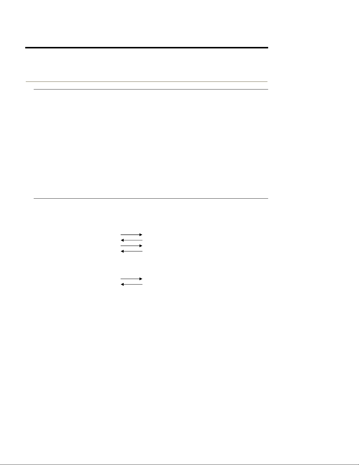
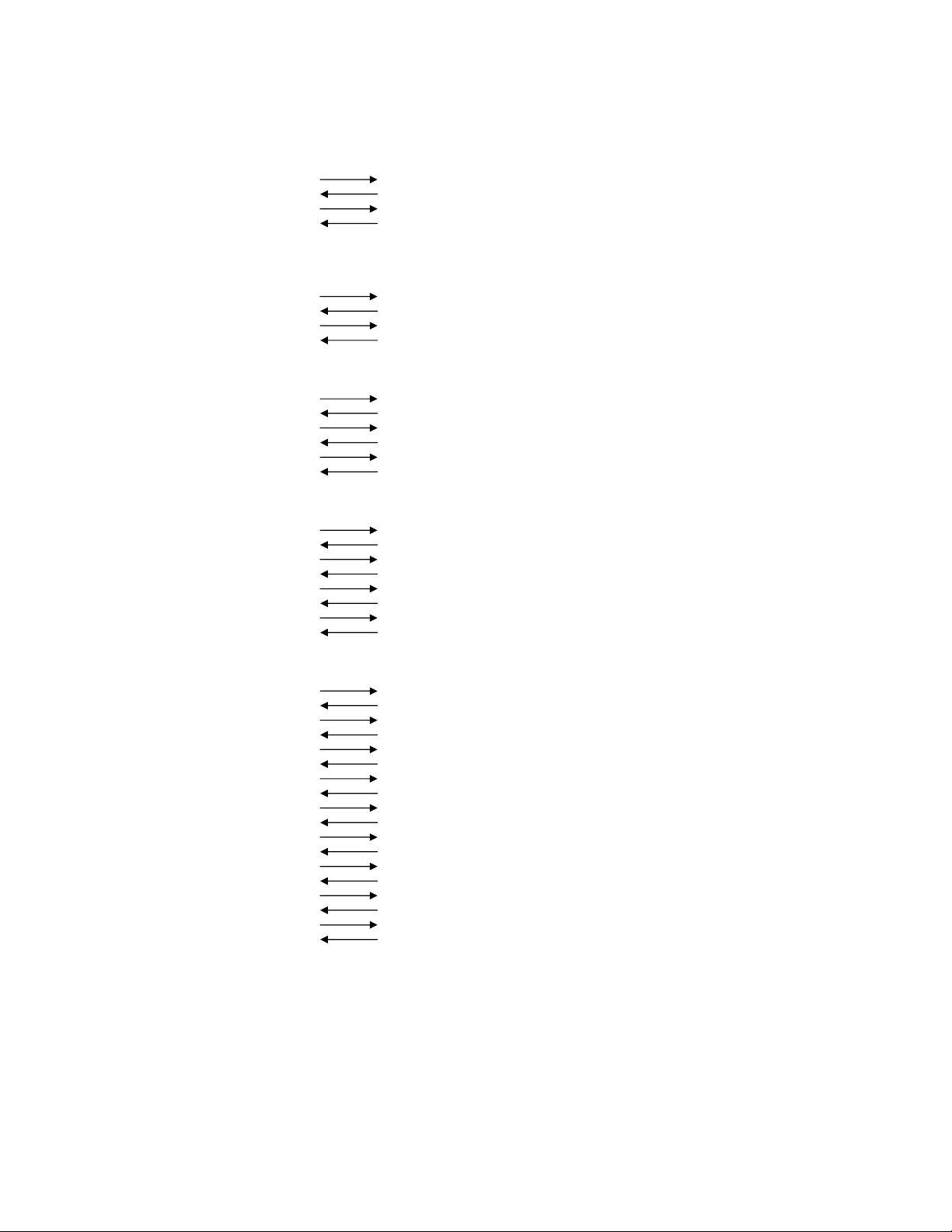
9.3.1 DTR Mode
Signals are controlled using the DTR line as BUSY flag.
Page 31 of 104
Page 32

SurePOS 100 Technical Reference
Figure 3-5. DTR Signal Timing
If a printer logic board error does not occur after the power is switched ON, the DTR signal line is asserted.
After the application confirms that DTR is asserted, the application program can send data to the printer at any
time. The printer logic drops the DTR signal when the empty space in the data buffer is below 256 bytes. After the
application detects that the DTR signal has dropped, transmission of data must stop. In DOS and OS/2 systems,
this buffer management can be completely handled by the operating system. No application programming is
required to implement this handshaking.
When the data in the data buffer is reduced to 256 bytes or less, the empty space in the data buffer is increased
and the printer logic asserts DTR. Then the printer is ready to receive more data.
Figure 3-6. DTR Data Buffer
9.3.1.1 Framing Error
A framing error occurs when space is detected at the stop bit. When a framing error or parity error
occurs for the data that is received, the printer prints out a "?" mark to indicate that the error occurred.
Page 32 of 104
Page 33

SurePOS 100 Technical Reference
9.3.1.2 Mechanical Error
Immediately after a mechanical error occurs, the printer logic drops DTR.
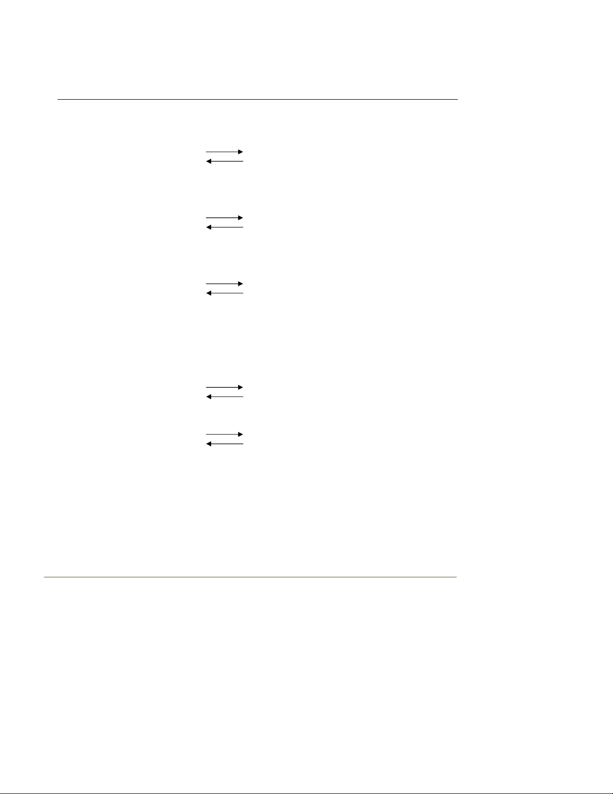
9.3.2 XON/XOFF Mode
This mode is enabled after the application program transmits the ESC command to the printer. The print
buffer must be empty or this command is ignored.
Figure 3-7. XON/XOFF DTR Signal Timing
After transmission of the ESC command, the printer outputs an XON (DC1 by control code; 11h by
hexadecimal data) to the system. When the application program receives the XON signal, it can transmit
data to the printer. If the data text is not sent from the application program, the printer logic outputs an
XON signal at 3 second intervals until the printer receives data.
The printer starts sending XOFF (DC3, 13h) when the empty space in the buffer reduces below 256
bytes. When the application receives the XOFF signal, it halts output of data. However, the printer logic
can continue receiving data until the buffer becomes completely full.
Output of the XON signal is resumed when the data in the buffer is printed out and drops to below 256
bytes.
Figure 3-8. XON/XOFF Data Buffer
Figure 3-9. XON/XOFF Status Byte
Page 33 of 104
Page 34

SurePOS 100 Technical Reference
9.3.3 STX-ETX Mode
Note: This mode is available only on the impact printer.
This mode is accessed from either DTR mode or XON/XOFF mode. To set this mode, the data buffer
must be empty.
The application program sends an ENQ code to the printer logic and acknowledges the printer status.
Then, the host computer checks that the printer buffer is empty. After the application program detects
that the buffer is empty, an STX code and data are transmitted. After one block of data is transmitted,
the application sends an ENQ code to the printer, then receives the printer status and check byte.
At this point, the system performs a status check. When the system determines that there was no error,
it transmits an ETX code that serves as text end code. After the printer logic receives the ETX code,
data in the data buffer is printed out. If an error occurs, a CAN code is transmitted by the application
program. In this instance, the data that was previously sent to the buffer is cleared, thus, the application
program must retransmit the same data to the printer logic.
Refer to Figure 3-10for a flowchart of this operation.
Figure 3-10. STX-ETX Mode Flowchart for Host
Page 34 of 104
Page 35

SurePOS 100 Technical Reference
The printer supports the code pages described in this document except that it does not support any
characters in positions 00h to 1Fh. Additional exceptions are documented on each code page.
Page 35 of 104
Page 36

SurePOS 100 Technical Reference
9.3.4 Star Mode Commands
Note: This section uses the following conventions:
The "value" in quotes is the ASCII hex representation of the value. For example, the ASCII value for the numeral
1 is 31h. The value n is the ASCII value. When n=1, the hex code 31h is represented.
The in brackets is either the absolute hex value or represents the ASCII control code. For example, if the value is
, then that represents the hex byte 01h, is hex byte 1Bh.
9.3.4.1 IBM Extended Commands
Function:
Select international character set
Code:
"T" n
1Bh 54h n
Outline:
Selects the international character set corresponding to the value set for n. n must be a 4-byte ASCII string where
the string value represents the code page and is one of the following:
Refer to the Star documents ("Related Publications and Diskettes") for the character sets for code pages
0000, 0001, and 0002 in the list that follows.
0000 Star USA/Europe
0001 Star IBM#1
0002 Star IBM#2
0003 Star Japan (Katakana)
0850 (Multilingual)
0852 (Eastern Europe)
0855 (Bulgaria)
0857 (Turkey)
0862 (Israel)
0864 (Arabic)
0866 (Russia)
0869 (Greece) - Impact printer only
0874 (Thailand)
The default international character set is 0850.
Function:
Select paper width
Code:
"Y" n
1Bh 59h n
Outline:
This command does nothing. Function on original SureOne printer is shown below.
Selects the paper width. n is a 1-byte ASCII string where n represents the paper width and is one of the following:
0 = 3.25 inch (82.5 mm) wide paper (power-up default)
1 = 2.25 inch (57.5 mm) wide paper
Function:
Set XON/OFF mode
Code:
Outline:
Sets XON/OFF mode
Function:
Set DTR mode
Code:
Page 36 of 104
Null (select paper width on original SureOne printer, not supported on MP512
Page 37

SurePOS 100 Technical Reference
Outline:
Sets DTR Mode
9.3.4.2 Existing Star Commands
Function:
Selects an international character set
Code:
"R" n
1Bh 52h n
Outline:
Selects an international character set according to the value of n, as shown below:
n
Character set
0
U.S.A.
1
France
2
Germany
3
U.K.
4
Denmark I
5
Sweden
6
Italy
7
Spain I
8
Japan
9
Norway
10
Denmark II
11
Spain II
12
Latin America
When the value of n is 0 to 9, 0(00h) to 9(09h) or "0"(30h) to "9"(39h) can be set. When the value of n is
10 to 12, 10(0Ah) to 12(0Ch) or "A"(41h) to "C"(43h) can be set.
Function:
Select IBM character set 2.
Code:
"6"
1Bh 36h
Outline:
Selects IBM character set 2.
Note:
This code is valid only when the character code set by the ESC T command is set for IBM character set 1 or 2.
Function:
Select IBM character set 1.
Page 37 of 104
Page 38

SurePOS 100 Technical Reference
Code:
"7"
1Bh 37h
Outline:
Selects IBM character set 1.
Note:
This code is valid only when the character code table set by the ESC T command is set for IBM character set 1 or
2.
Function:
Select normal character spacing
Code:
"M"
1Bh 4Dh
Outline:
This code is valid only when received at the beginning of a line. For the impact printer, the maximum number of
print columns varies with the setting of the paper width DIP switch.
Impact Printer:
7 x 9 half-dots
3.25-in. paper - maximum print columns = 40
2.25-in. paper - maximum print columns = 28
Characters per inch (CPI) = 15.4
Thermal Printer:
12-dot pitch printing
Maximum print columns = 48
Characters per inch (CPI) = 16.9
Function:
Select medium character spacing
Code:
"g"
1Bh 67h
Outline:
Prints 12-dot pitch characters with 2-dot spacing between characters.
Function:
Select wide character spacing
Code:
"P"
1Bh 50h
Outline:
This code is valid only when received at the beginning of a line. For the impact printer, the maximum number of
print columns varies with the setting of the paper width DIP switch.
Impact Printer:
5 x 9 two-pulse printing
3.25-in. paper - maximum print columns = 33
2.25-in. paper - maximum print columns = 23
Characters per inch (CPI) = 12.8
Thermal Printer:
15-dot pitch printing
Maximum print columns = 38
Characters per inch (CPI) = 13.5
Function:
Select extra-wide character spacing
Page 38 of 104
Page 39

SurePOS 100 Technical Reference
Code:
":"
1Bh 3Ah
Outline:
This code is valid only when received at the beginning of a line. For the impact printer the maximum number of
print columns varies with the setting of the width DIP switch.
Thermal Printer:
5 x 9 three-pulse printing
3.25-in. paper - maximum print columns = 22
2.25-in. paper - maximum print columns = 15
Characters per inch (CPI) = 8.5
Thermal Printer:
16-dot pitch printing
Maximum print columns = 36
Characters per inch (CPI) = 12.7
Function:
Set the character spacing
Code:
n
1Bh 20h n
Outline:
Sets the space between characters to n dots, where n is a number from 0 to 15. When the value of n is 0 to 9,
0(00h) to 9(09h) or "0"(30h) to "9"(39h) can be set. When the value of n is 10 to 15, 10(0Ah) to 15(0Fh) or
"A"(41h) to "F"(46h) can be set.
Function:
Select 2X character width mode
Code:
0Eh
Outline:
Data following this code is printed in double-width characters.
Same as "W" "1" or "W" .
Function:
Cancel 2X character width mode
Code:
14h
Outline:
Cancels expanded character width set by or "W" code. Data following this code is printed out in normal width
characters.
Same as "W" "0" or "W" .
Function:
Set expanded character width mode
Code:
"W" "n" or "W" <n>
1Bh 57h "n" or 1Bh 57h
Outline:
Data following this code is printed in expanded-width characters.
n
Character width
0
normal
Page 39 of 104
Page 40

SurePOS 100 Technical Reference
1
double
2
triple
3
quadruple
4
quintuple
5
sextuple
Note: Numbers 2-5 are for the thermal printer only.
Function:
Select 2X character height mode
Code:
."
1Bh 0EH
Outline:
Data following this code is printed in double height characters. Same as "h" "1" or "h" .
Function:
Select 2X character height mode
Code:
."
1Bh 14h
Outline:
Cancels expanded character height set by or "h" code. Data following this code is printed out in normal height
characters. Same as "h" "0" or "h" .
Function:
Set expanded character height
Code:
"h" "n" or "h"
1Bh 68h "n" or 1Bh 68h
Outline:
Prints characters with expanded character height after the code is received.
However, the bit image mode "K" and "L" are excluded for the impact printer.
Note:
When combined with code, this code enables printing of the characters twice the normal vertical and horizontal
size.
This code is not combined with the inverted print mode code for the impact printer.
Character Height - n
n
Character Height
0
normal
1
double
2
triple
3
quadruple
4
quintuple
5
sextuple
Page 40 of 104
Page 41

SurePOS 100 Technical Reference
Note: Numbers 2 through 5 are for the thermal printer only.
Function:
Select emphasized print mode
Code:
"E"
1Bh 45h
Outline:
Data following this code is printed in the emphasized print mode. In this mode, the only unidirectional printing is
performed for the Impact printer.
Function:
Select emphasized print mode
Code:
"G"
1Bh 47h
Outline:
Causes subsequent characters to be emphasized.
Function:
Cancel emphasized print mode
Code:
"F"
1Bh 46h
Outline:
Cancels emphasized print mode.
Function:
Cancel emphasized printing
Code:
"H"
1Bh 48h
Outline:
Cancels emphasized printing.
Function:
Select underline mode
Page 41 of 104
Page 42

SurePOS 100 Technical Reference
Code:
"-" "n" or "-"
1Bh 2Dh "n" or 1Bh 2Dh
Outline:
When n=1, data following this code is printed out underlined, except for the spaces generated by horizontal tabs.
When n=0, underline mode is cancelled.
Function:
Select overline mode
Code:
"_" "n" or "_"
1Bh 5Fh "n" or 1Bh 5Fh
Outline:
When n=1, data following this code is printed out with an overline, except for the spaces generated by horizontal
tabs. When n=0, overline mode is cancelled.
Function:
Select highlighted print mode
Code:
"4"
1Bh 34h
Outline:
Prints with highlighted characters. For the impact printer, if an underline, overline, or inverted print command is
input while the highlighted print mode is in effect, the highlighted mode cancels and the new input command
executes. If a highlighted print command is received while the underline, overline, or inverted print mode is in
effect, the previously set mode cancels and the new input command (highlighted) executes.
Function:
Cancel highlighted print mode
Code:
"5"
1Bh 35h
Outline:
Cancels highlighted print mode.
Function:
Select inverted print mode
Code:
0Fh
Outline:
Data following this code is printed out in inverted characters. For the impact printer, this code is valid only when
input at the beginning of a line. For the impact printer, normal and inverted characters cannot be mixed on the
same line.
Function:
Cancel inverted print mode
Code:
12h
Outline:
Cancels the inverted character mode. For the impact printer, this code is valid only when input at the beginning of
a line.
Page 42 of 104
Page 43

SurePOS 100 Technical Reference
9.3.5 Control Codes Used for Line Spacing
Function:
Line feed
Code:
0Ah
Outline:
Data in the line buffer is printed out and one line is fed. If no data is in the line buffer before this code is received,
the printer feeds one line.
Function:
Carriage return
Code:
0Dh
Outline:
Functions the same as the code.
Notes:
The default DIP switch setting for the impact printer ignores this code.
The default memory switch setting for the thermal printer ignores this code.
Function:
Set normal line spacing
Code:
"z" "1" or "z"
1Bh 7Ah 31h or 1Bh 7Ah 01h
Outline:
Line spacing is set at 1/6 inch for the impact printer and 4 mm for the thermal printer after this code is received.
Function:
Set compact line spacing
Code:
"0"
1Bh 30h
Outline:
Line spacing is set at 1/8 inch for the impact printer and 3 mm for the thermal printer after this code is received.
Function:
Feed paper n lines
Code:
"a" n
1Bh 61h n
Definition Range:
1 <= n <= 127
Outline:
After data in the line buffer is printed, paper feeds n lines.
Function:
Set tight line spacing
Code:
"1"
1Bh 31h
Outline:
Line spacing is set at 7/72 inch for the impact printer and 3 mm for the thermal printer after this code is received.
Page 43 of 104
Page 44

SurePOS 100 Technical Reference
Function:
Define n/72 inch line feed
Code:
"A" n
1Bh 41h n
Definition Range:
0 <= n <= 85 (default n = 12)
Outline:
Line feed is set at n/72 inch after this code is received.
This code sets the feed a n/72 inch with the "2" code.
Function:
Set n/72 inch line feed
Code:
"2"
1Bh 32h
Outline:
Sets the line feed at a defined value with the "A"
Function:
One-time micro line feed
Code:
"J" n
1Bh 4Ah n
Definition Range:
1 <= n <= 255
Outline:
Activates the n/72 inch paper feed once for the impact printer, and n/4 mm for the thermal printer
Function:
One-time n/4 mm backfeed
Code:
"j" n
1Bh 6Ah n
Outline
Feeds the paper back n/4 mm once only. The value of n is 1 to 255. Space setting for one line is not changed.
This command can also feed the paper back to the page before the current page. In this case, the position of the
line on the previous page is determined by the page length control.
Function:
One-time n/8 mm feed
Code:
"I" n (I = capital i)
1Bh 49h n
Outline:
Performs a line feed n/8 mm once only. The value of n is 1 to 255. Space setting for lines is not changed.
Function:
Set crowded line spacing
Code:
"z" "0" or "z"
1Bh 7Ah 30h or 1Bh 7Ah 00h
Outline:
Line feed is set at 1/12 inch for the impact printer and 3 mm for the thermal printer after this code is received.
Page 44 of 104
Page 45

SurePOS 100 Technical Reference
Function:
Set n/144 inch line feed
Code:
"y" n
1Bh 79h n
Definition Range:
1 <= n <= 255
Outline:
Line feed is set at n/144 inch after this code is received.
Function:
Set n/216 inch line feed
Code:
"3" n
1Bh 33h n
Definition Range:
1 <= n <= 255
Outline:
Line feed is set at n/216 inch after this code is received.
The actual line feed is set at INT (n X 2/3 + 0.5)/144 inch.
9.3.6 Control Codes Used for Page Layout
Function:
Form feed
Code:
0Ch
Outline:
After data in the buffer is printed, paper feeds to the top of the next page.
Function:
Set page length in lines
Code:
"C" n
1Bh 43h n
Definition Range:
Default value = 42,
1 <= n <= 255 (Impact printer)
1 <= n <= 127 (Thermal printer)
Outline:
Sets the page length at n lines.
Function:
Set page length in inches
Code:
"C" n
1Bh 43h 00h n
Definition Range:
1 <= n <= 127 (Impact printer)
1 <= n <= 22 (Thermal printer)
Outline:
Sets the page length at n inches.
Function:
Page 45 of 104
Page 46

SurePOS 100 Technical Reference
Execute vertical tab
Code:
0Bh
Outline:
Feeds the paper to the next vertical tab set position. When a vertical tab is not set, line feed is not performed. If
the current line is at or below the last vertical tab set position, the paper feeds to the top of the next page.
Function:
Set vertical tab position
Code:
"B" n1 n2...nk
1Bh 42h n1 n2...nk 00h
Definition Range:
1 <= n1 <n2 <n3...<nk <= 255, 1 <= k <= 16
Outline:
Cancels all current vertical tab positions and sets new vertical tab positions at lines n1, n2, where n1, n2 are
numbers between 1 and 255. A maximum of 16 vertical tab positions can be set. The tab positions must be
specified in ascending order; any violation of ascending order terminates the tab position list. Standard
termination is by the control code. The vertical tab positions are set in terms of the current line spacing and do not
move if the line spacing is changed later.
Note:
If a tab set position <nk> is equivalent or smaller than <nk - 1> just preceding the tab set position, setting of
vertical tab is assumed as complete.
Function:
Set bottom margin
Code:
"N" n
1Bh 4Eh n
Definition Range:
Default value = 0
0 <= n <= 255 (Impact printer)
0 <= n <= 127 (Thermal Printer)
Outline:
Sets bottom margin to n lines.
Function:
Cancel bottom margin
Code:
"O" (letter O)
1Bh 4Fh
Outline:
Cancels bottom margin.
Function:
Page 46 of 104
Page 47

SurePOS 100 Technical Reference
Set left margin
Code:
"l" n (l = lowercase L)
1Bh 6Ch n
Definition Range:
0 <= n <= (right margin - 2) (Impact Printer)
0 <= n <= (right margin - 2) (Thermal printer)
Outline:
Sets the left margin at column n in the current character pitch. The left margin does not move if the character pitch
is changed later. For the impact printer, the left margin must be at least two columns to the left of the right margin
and within the limits above. For the thermal printer, the left margin must allow a line length of at least 36 mm,
otherwise the command is ignored.
Function:
Set right margin
Code:
"Q" n
1Bh 51h n
Definition Range:
2 <= n <= (maximum number of print columns) - (Impact Printer)
1 <= n <= 255 (maximum number of print columns) - (Thermal Printer)
Outline:
Sets the right margin at column n in the current character pitch. Column n becomes the last character position of
the line. The right margin does not move if the character pitch is changed later. For the impact printer, the right
margin must be at least two columns to the right of the left margin and within the limits above. For the thermal
printer, the right margin must allow a line length of at least 36 mm, otherwise the command is ignored.
Function:
Execute horizontal tab.
Code:
09h
Outline:
The print position skips to the next horizontal tab position in line. When no horizontal tab position is set, this code
is ignored. (Underlining and overlining do not take place in the spaces between characters set with the horizontal
tab function.)
Function:
Set horizontal tab position
Page 47 of 104
Page 48

SurePOS 100 Technical Reference
Code:
"D" n1 n2...nk
1Bh 44h n1 n2...nk 00h
Definition Range:
1 <= n1 <n2 <n3...<nk <= (maximum no. of print columns), 1 <=k <=16
Outline:
Cancels all current horizontal tab positions and sets new tab positions at columns n1, n2, etc. in the current
character pitch. The maximum number of horizontal tab positions allowed is 16. The tab positions must be
specified in ascending order; any violation of ascending order terminates the tab position list. Standard
termination is by the control code. To clear all tab positions, specify "D" .
Note:
When the horizontal tab set position <nk> is equivalent or smaller than <nk - 1> (which is the column just
preceding the set tab position) vertical tab setting is assumed as complete.
9.3.7 Control Codes Used for Graphics Printing
Function:
Normal density graphics
Code:
"K" n1 m1 m2....
1Bh 4Bh n1 00h m1 m2....
Definition Range:
1 <= n1 <= 200 (Impact Printer)
1 <= n1 <= 192 (Thermal Printer)
Outline:
Executes normal density dot graphics. The total number of bit image data bytes in one line is equal to n1. The
printer ignores any data bytes over the specified amount allowed in one line. When the bit image print is finished,
the printer automatically returns to character mode. For the Impact printer, each data bit controls 1 dot. For the
Thermal printer, each data bit controls a 3 x 3 dot block (0.375 mm x 0.375 mm).
Example:
The following design is created using the bit image in the table. Because the volume of data is 30, n1 = 1Eh.
Data Binary Hex Data Binary Hex Data Binary Hex
m1 00000001 01 m11 00111110 3E m21 00111110 3E
m2 00011110 1E m12 00000010 02 m22 00101110 2E
m3 00111110 3E m13 00000010 02 m23 00101110 2E
m4 01011111 5E m14 00111110 3E m24 00111110 3E
m5 00011111 1F m15 00111110 3E m25 00101111 2F
m6 01011110 5E m16 00101111 2F m26 00101111 2F
m7 00011110 1E m17 00010111 2F m27 00111110 3E
m8 00111111 3F m18 00111110 3E m28 00111110 3E
m9 00101111 2F m19 00101110 2E m29 00000010 02
Page 48 of 104
Page 49

SurePOS 100 Technical Reference
m10 00111110 3E m20 00101110 2E m30 00000010 02
Function:
High-density graphics
Code:
"L" n1 n2 m1 m2....
1Bh 4Ch n1 n2 m1 m2....
Definition Range:
1 <= n1 + 256 X n2 <= 400 - (Impact printer)
1 <= n1 + 256 X n2 <= 576 - (Thermal printer)
Outline:
Executes high-density dot graphics determined by n1 and n2 The total number of bit image data bytes in one line
is equal to n1 + n2 X 256. Refer to K as to the relationship between the dot position and the bit number. The
printer ignores any data bytes over the specified amount allowed in one line.
When the bit image printing is finished, the printer automatically returns to the character mode.
Note:
For the impact printer, dots cannot overlap each other in the horizontal direction.
Function:
Print fine-density bit image
Code:
"k" n d1...dk
1Bh 6Bh n 00h d1...dk
Outline:
Prints a bit image using 1 horizontal dot and 1 vertical dot for 1 dot of input data. n is designated by the number of
data bytes in the horizontal direction and n must be within the range 1 to 72. The data is ignored if it is longer than
72 digits or goes beyond the right margin. k = n x 24.
Function:
Print fine density graphics
Code:
"X" n1 n2 d1...d
1Bh 58h n1 n2 d1...dk
Outline:
Prints a bit image of the input data using horizontal and vertical resolutions of 8 dots/mm. Data extending past the
right margin is ignored. k = (n1 + n2 x 256) x 3. 1 <= n1+n2 x 256 <= 576
9.3.8 Control Codes Used for Character Downloading
Page 49 of 104
Page 50

SurePOS 100 Technical Reference
Function:
Definition of download characters for impact printer
Code:
When 7 X 9 (half-dots) font matrix is set (default setting):
"&" n1 n2 [m0 m1 m2 m3 m4 m5 m6 m7] n2 - n1 + 1
1Bh 26h 00h n1 n2 [m0 m1 m2 m3 m4 m5 m6 m7] n2 - n1 + 1
When 5 X 9 font matrix is set:
"&" n1 n2m0 m1 m2 m3 m4 m5] n2 - n1 + 1
1Bh 26h 00h n1 n2 [m0 m1 m2 m3 m4 m5] n2 - n1 + 1
Definition Range:
21h <= n1 <= n2 <= n2 7Fh, m0 = 00h or m0 = 80h
Outline:
Defines download characters.
Up to 10 download characters can be defined and stored in the printer's RAM. Defining of download characters
begins with character code n1 and completes with n2. When only one character is defined, n1= n2. m0 indicates
the relationship between the character pattern and the print head. m1 m2...indicate the character pattern.
Note:
When the 7 X 9 (half-dots) font matrix is set (the default setting), printing of adjacent horizontal dots is not
allowed.
Function:
Enable download character set
Code:
"%" "1" or "%"
1Bh 25h 31h or 1Bh 25h 01h
Outline:
Enables the download character set. Download characters defined by the ESC & code cannot be printed until
enabled by this command.
Function:
Disable download character set
Code:
"%" "0" or "%"
1Bh 25h 30h or 1Bh 25h 00h
Outline:
Disables the selected download character set and selects the built-in character set. When power to the printer is
initially switched on, the built-in character set is selected.
Example:
For the Impact printer to print a download character when the 7 x 9 (half-dots) font matrix is set:
Page 50 of 104
Page 51

Design the download character to be used at code positions 21h, 22h, and 23h
SurePOS 100 Technical Reference
Define the download characters. When character addresses where the download character are desired to be 21h,
22h, 23h, n1 = 21h) and n2 = 23h.
If the relationship between the character pattern data and the printing head is specified to "not use pin 9", m0 =
80h is obtained. When data m1 to m7 are converted into hexadecimal data, they are indicated as shown in Table
3-5.
Table 3-5. Character Bit Images
Data Binary Hex Data Binary Hex Data Binary Hex
m1 10100000 A0 m1 10011000 98 m1 00111000 3C
m2 00000000 00 m2 01100100 64 m2 01000010 42
m3 10100000 A0 m3 10000010 82 m3 10100101 A5
m4 00011111 1F m4 00000001 01 m4 00000000 00
m5 10100000 A0 m5 10000010 82 m5 10100101 A5
m6 00000000 00 m6 01100100 64 m6 01000010 42
m7 10100000 A0 m7 10011000 98 m7 00111000 3C
Example of Transmitting Data
Definition
of
download
characters
Selecting
the
download
character
set
Character
codes
Canceling
the
download
character
set
Character
codes
Page 51 of 104
1Bh 26h 00h 21h 23h 80h A0h 00h A0h 1Fh A0h 00h A0h 80h 98h 64h 82h 01h 82h 64h 98h 80h 3Ch
42h A5h 00h A5h 42h 3Ch
1Bh 25h 31h
21h 22h 23h 0Ah
1Bh 25h 30h
21h 22h 23h 0Ah
Page 52

SurePOS 100 Technical Reference
Function:
Define download character for thermal printer
Code:
"&" n m1 m2 ... m48
1Bh 26h 01h 01h m1 m2 ... m48
Code:
"&" "1" "1" n m1 m2 ... m48
1Bh 26h 31h 31h m1 m2 ... m48
Outline:
Defines one new character and stores it in RAM for later use. n is the character code of the character defined and
must be from 32 to 127. If the maximum of 32 external characters have already been stored, the oldest stored
external character is deleted so that a new external character can be stored. The character matrix is 12 dots wide
and 24 dots high.
Function:
Delete a download character
Code:
"&" n
1Bh 26h 01h 00h n
Code:
"&" "1" "0" n
1Bh 26h 31h 30h n
Outline:
Deletes the download character that was assigned the value n.
9.3.9 Cash Drawer Commands
Function:
Adjust drive pulse width for cash drawer
Code:
n1 n2
1Bh 07h n1 n2
Definition Range:
1 <= n1 <= 127, 1 <=n2 <= 127 (default setting n1 = n2 = 20)
Outline:
Adjusts drive pulse width for peripheral devices requiring other than standard 200-ms pulse time and delay time.
Energizing time = 10 X n1 (ms)
Delay time = 10 X n2 (ms)
Executed by , codes.
Note:
n1 and n2 do not need to be specified for IBM or other cash drawers capable of being driven by a standard 200ms pulse.
Function:
Deferred open command for cash drawer
Code:
07h
Outline:
Executes an open command for cash drawer after all previous bytes in the printer logic buffer have been
processed.
Function:
Immediate drive command for cash drawer
Code:
Page 52 of 104
Page 53

1Ch
Outline:
Executes drive pulse for cash drawer immediately. This code differs from the code in that when the printer
receives an code, the command is executed immediately. The code is stored in the data buffer in the same
manner as other codes, and executed in the order in which they are received.
SurePOS 100 Technical Reference
For additional information about cash drawer commands and the interfaces for the cash drawer, see
"Cash Drawer"
9.3.10 Other Control Codes
Function:
Sound buzzer
Code:
1Eh
Outline:
Generates a short alarm.
Function:
Cancel print data in buffer
Code:
18h
Outline:
Clears data buffer and line buffer.
For the impact printer, clears the data in the data buffer in the STX-ETX mode.
Function:
Select unidirectional print mode
Code:
"U" "1" or "U"
1Bh 55h 31h or 1Bh 55h 01h
Outline:
The impact printer prints only when the print head moves from left to right.
Function:
Select bidirectional print mode
Code:
"U" "0" or "U"
1Bh 55h 30h or 1Bh 55h 00h
Outline:
The impact printer returns to the standard bidirectional print mode. This mode is set automatically when the
printer power is switched on.
Function:
Initialize printer
Code:
"@"
1Bh 40h
Outline:
Cancels the various conditions set after the power was switched on and resets the printer to the initial settings in
effect when the printer is switched on. In this instance, contents of the line buffer and the data buffer are not
cleared.
Page 53 of 104
Page 54

SurePOS 100 Technical Reference
Function:
Enquiry
Code:
05h
Outline:
Causes the control board to transmit a status byte. For the Impact printer, when this code is received after
receiving text data in the STX-ETX mode, the control board transmits the status and check byte.
The status byte definition is as follows:
Bit
Definition
7
Cash drawer status, 0 = open
6
Printer buffer overflow = 1
5
Printer buffer empty = 1
4
Always 0
3
Paper empty = 1
2
Mechanical error = 1
1
Framing error = 1
0
Parity error = 1
Function:
Reset the printer hardware
Code:
"?"
1Bh 3Fh 0Ah 00h
Outline:
Resets the printer hardware.
Function:
Enter STX-ETX mode
Code:
02h
Outline:
Sets the STX-ETX mode.
Function:
Terminate STX-ETX mode
Code:
03h
Outline:
Terminates the STX-ETX mode and prints out the text data.
Function: Null (select validation printing on the original printer), MP512 Only
Code: <GS> data <LF>
1Dh Data 0AH
Outline: This command does nothing
Page 54 of 104
Page 55

Function:
Select validation printing
Code:
data
1Dh data 0Ah
Outline:
This command does nothing. Original SureOne printer function shown below for reference.
Prints up to 32 columns of the 15.4 CPI size characters on one line.
Notes:
Character data and immediate execution command are valid for data.
Printing modes (such as emphasized, inverted, expanded character modes) which were set before validation
printing are invalid during validation printing. These modes become valid again after validation printing is
completed.
Function:
Select bar code printing
Code:
"b" n1 n2 n3 n4 di ... dk
1Bh 62h n1 n2 n3 n4 di ... dk 1Eh
Outline:
Prints bar code according to the value of n1, as follows:
n1
Type of bar code
0
UPC-E
1
UPC-A
2
JAN/EAN-8
3
JAN/EAN-13
4
Code 39
5
ITF
6
Code 128
7
Code 93
8
NW-7
SurePOS 100 Technical Reference
Null, was select validation printing on original SureOne offering
The value of n1 can be set to 0(00h) or 8(08h) or "0"(30h) to "8"(38h).
n2
Whether character below bar code or line feed is printed
1
No. Line feed is performed after execution of command.
2
Yes. Line feed is performed after execution of command.
3
No. Line feed is not performed after execution of command
4
Yes. Line feed is not performed after execution of command.
The value of n2 can be set to 1(01h) to 4(04h) or "1"(31h) to "4"(34h).
n3
Page 55 of 104
Page 56

Mode of bar code (UPC-E, UPC-A, JAN/EAN-8, JAN/EAN-13, CODE 128, CODE 93)
1
Minimum module of 2 dots
2
Minimum module of 3 dots
3
Minimum module of 4 dots
SurePOS 100 Technical Reference
Mode of barcode (Code 39, NW-7, ITF)
n3 Code 39 & NW-7 ITF
1 Narrow : wide 2:6 dots 2:5 dots
2 Narrow : wide 3:9 dots 4:10 dots
3 Narrow : wide 4:12 dots 6:15 dots
4 Narrow : wide 2:5 dots 2:4 dots
5 Narrow : wide 3:8 dots 4:8 dots
6 Narrow : wide 4:10 dots 6:12 dots
7 Narrow : wide 2:4 dots 2:6 dots
8 Narrow : wide 3:6 dots 3:9 dots
9 Narrow : wide 4:8 dots 4:12 dots
When the value of n3 is UPC-E, UPC-A, JAN/EAN-8, JAN/EAN-13, Code 128 or Code 93, 1(01h) to
3(03h) or "1"(31h) to "3"(33h) can be set. When the value of n3 is CODE 39, NW-7 or ITF, 1(01h) to
9(09h) or "1"(31h) to "9"(39h) can be set.
n4 Height of Bar Code:
The height of the bar code can be up to 255 dots (31.9 mm /.1.256 in. ). If the bar code is higher than
the line feed amount, the line feed amount is automatically multiplied by an integer.
di...dk
Bar code data
UPC-E/UPC-A: K = 11 (or 12)
The check digit at the 12th digit is automatically added, and ignored even if it is specified.
JAN/EAN-8: K = 7 (or 8)
The check digit at the 8th digit is automatically added, and ignored even if it is specified.
JAN/EAN-13: K = 12 (or 13)
The check digit at the 13th digit is automatically added, and ignored even if it is specified.
CODE 39:
The value of k is optional, and the maximum value also differs according to the modes (21 digits maximum in
mode 7). The start/stop code (" * ") is automatically added.
ITF:
The value of k is optional, and the maximum value also differs according to the modes (40 digits maximum in
mode 4). If the data is number of an odd digits, 0 is automatically added at the beginning of the data.
Code 128:
The value of k is optional, and the maximum value also differs according to the modes and the types of character
number (51 digits maximum in mode 1). The check character is automatically added.
CODE 93:
The value of k is optional, and the maximum value also differs according to the modes and the types of character
(30 digits maximum in mode 1). The check characters (C and K) are automatically added.
NW-7:
The value of k is optional, and the maximum value also differs according to the modes and the types of character
number (29 digits maximum in mode 7). The start/stop code is also contained in the data (it is not automatically
added).
The bar code printing start position is at the upper end of the current line. If the bar code is
positioned beyond the right margin, neither the bar code nor the character below the bar code
will be printed.
Data of CODE 128 and CODE 93
When is used in a command, some kinds of control code cannot be sent by the host PC. The control code should
be sent as the data as shown below:
Page 56 of 104
Page 57

SurePOS 100 Technical Reference
When sending the following data, express as a set of two characters. Express "% (25h)" as "%0
(25h - 30h)". Add "40h - 5Fh" after "%" for the control codes (00h - 1Fh). Express the control
code (7Fh) as "%5(25h - 35h)". Add "1 - 4 (31h - 34h)" after "%" for the function code. Add "6 -
8 (36h - 38h)" after "%" for the start code.
9.3.11 Control Codes
Code Format
NUL 00h %@ 25h 40h
SOH 01h %A 25h 41h
STX 02h %B 25h 42h
ETX 03h %C 25h 43h
EOT 04h %D 25h 44h
ENQ 05h %E 25h 45h
ACK 06h %F 25h 46h
BEL 07h %G 25h 47h
BS 08h %H 25h 48h
HT 09h %I 25h 49h
LF 0Ah %J 25h 4Ah
VT 0Bh %K 25h 4Bh
FF 0Ch %L 25h 4Ch
CR 0Dh %M 25h 4Dh
SO 0Eh %N 25h 4Eh
SI 0Fh %O 25h 4Fh
DLE 10h %P 25h 50h
DC1 11h %Q 25h 51h
DC2 12h %R 25h 52h
DC3 13h %S 25h 53h
DC4 14h %T 25h 54h
NAK 15h %U 25h 55h
SYN 16h %V 25h 56h
ETB 17h %W 25h 57h
CAN 18h %X 25h 58h
EM 19h %Y 25h 59h
SUB 1Ah %Z 25h 5Ah
ESC 1Bh %[ 25h 5Bh
FC 1Ch %Ñ 25h 5Ch
GS 1Dh %] 25h 5Dh
RS 1Eh %^ 25h 5Eh
US 1Fh %_ 25h 5Fh
DEL 7Fh %5 25h 35h
9.3.11.1 Special Code Format
Code Format
% 25h %0 25h 30h
9.3.11.2 Function Codes Format
Code Format
FNC1 %1 25h 31h *
FNC2 %2 25h 32h *
FNC3 %3 25h 33h *
FNC4 %4 25h 34h *
* = For CODE 128 only
Page 57 of 104
Page 58

SurePOS 100 Technical Reference
9.3.11.3 Start Codes Format
Code Format
START A %6 25H 36H *
START B %7 25H 37H *
START C %8 25H 38H *
* = For CODE 128 only
Function:
Full-cut command to the auto-cutter
Code:
"d" "0" or "d"
Outline:
Cuts the paper partially when memory switch #2, bit C is set to 0. If memory switch #2, bit C is set to 1, the paper
is fed 18 mm (0.7 in.) and then cut fully. When the auto-cutter is invalid (set by memory switch #2, bit 8), this
command is ignored.
Function:
Partial-cut command to the auto-cutter
Code:
"d" "1" or "d"
Outline:
Cuts the paper partially when memory switch #2, bit C is set to 0. If memory switch #2, bit C is set to 1, the paper
is fed 18 mm (0.7 in.) and then cut partially. When the auto-cutter is invalid (set by memory switch #2, bit 8), this
command is ignored.
Function:
Set memory switch
Code:
"#N,n1n2n3n4"
1Bh 23h N 2Ch n1n2n3n4 0Ah 00h
Outline:
Set the memory switch. The memory switch is a "soft" dip switch to set the printer configuration. After the memory
switch command has been sent, the setting can be enabled by setting the printer OFF and ON again or sending
the printer reset command "?" to the printer. Changed memory switch settings are stored in EEPROM and these
settings will be stored permanently on the printer logic circuit board.
Table 3-6. Default Memory Switch Settings (n1n2n3n4)
N Standard Japanese Korean Simplified
Chinese
0 0000 0010 0010 0010 0010
1 0100 0100 0100 0100 0100
2 0100 0100 0100 0100 0100
3 0300 0000 0000 0010 0010
4 0000 0000 0000 0000 0000
E 0000 0000 0000 0000 0000
Traditional
Chinese
Note: Memory switch "D" is not shown because it does not have a default setting.
To set the memory switches for the Standard, Traditional Chinese, or Simplified Chinese versions to
match the Star TSP200 series printer, send the following commands to the printer:
"#3,0000"
"?"
Page 58 of 104
Page 59

SurePOS 100 Technical Reference
Note: On the Standard version, this will change the default power-on character set from "Multilingual"
(code page 850) to Star "Normal".
On the Simplified Chinese and Traditional Chinese versions, this will change number of characters per
line from 44 to 38 alphanumeric, and from 22 to 19 DBCS.
N
Memory switch number (0, 1, 2, 3, 4, D, E)
n1n2n3n4
Mode settings (see details in Table 3-7
through Table 3-18).
Table 3-7. Memory Switch #0
n Bit Function 0 1 Notes
n1 F
n1 E
n1 D
n1 C
n2 B
n2 A
n2 9
n2 8
n3 7
n3 6
n3 5
n3 4 DBCS Not available on Standard version
n4 3 cut Full
n4 2 Form
n4 1
n4 0
cut
feed
Partial
cut
Feed
and
cut
Table 3-8. Memory Switch #1
n Bit Function 0 1 Notes
n1 F
n1 E
n1 D
n1 C
n2 B
n2 A
n2 9
n2 8
n3 7
n3 6
Page 59 of 104
Page 60

n3 5
n3 4 Zero style Normal Slash
n4 3 International
character
set
n4 2 International
character
set
n4 1 International
character
set
n4 0 International
character
set
See
Table
3-9
See
Table
3-9
See
Table
3-9
See
Table
3-9
SurePOS 100 Technical Reference
See
Standard and Japanese versions only
Table
3-9
See
Standard and Japanese versions only
Table
3-9
See
Standard and Japanese versions only
Table
3-9
See
Standard and Japanese versions only
Table
3-9
Table 3-9. International Character Set
n4 Country
0 USA
1 France
2 Germany
3 UK
4 Denmark #1
5 Sweden
6 Italy
7 Spain #1
8 Japan
9 Norway
A Denmark #2
B Spain #2
C Latin America
D Reserved
E Reserved
F Reserved
Table 3-10. Memory Switch #2
n Bit Function 0 1 Notes
n1 F
n1 E
n1 D
n1 C "d" Cut Feed & cut
n2 B
n2 A
Page 60 of 104
Page 61

n2 9
n2 8 Auto-cutter Invalid Valid
n3 7
n3 6
n3 5
n3 4
n4 3
n4 2
n4 1
n4 0 Paper Near End
sensor
SurePOS 100 Technical Reference
Invalid Valid
Table 3-11. Memory Switch #3
n Bit Function 0 1 Notes
n1 F
n1 E
n1 D
n1 C Shift JIS
Kanji
n2 B
n2 A
n2 9 Character
table
n2 8 Character
table
n3 7
n3 6
n3 5
n3 4 Print
Column
n4 3
n4 2
n4 1 code Invalid Valid
n4 0 Line Pitch 4 mm 3 mm
Valid Invalid Japanese version only
See
See
Table
3-12
See
Table
3-12
See
Table
3-13
Standard and Japanese versions only
Table
3-12
See
Standard and Japanese versions only
Table
3-12
See
Table
3-13
Table 3-12. Character Table
n2 Character Table
0 Normal
1 IBM
Page 61 of 104
Page 62

2 Katakana
3 Multilingual (CP850)
SurePOS 100 Technical Reference
Table 3-13. Character Table
n3 0 0 1 1
Version ANK DBCS ANK DBCS
Standard 48 N/A 38 N/A
Japanese 48 22 38 19
Korean 44 22 38 19
Simplified Chinese 38 19 44 22
Traditional Chinese 38 19 44 22
Table 3-14. Memory Switch #4
n Bit Function 0 1 Notes
n1 F
n1 E
n1 D
n1 C
n2 B
n2 A
n2 9
n2 8 Buffer
size
n3 7
n3 6
n3 5
n3 4 Busy
Condition
n4 3
n4 2
n4 1
n4 0
4 KB 45
bytes
See
See
Table
Table
3-15
3-15
ESC/POS mode only
Table 3-15. Busy Condition
Printer Bit 4
Until printer ready after power on Busy Busy
Until printer ready after I/F reset Busy Busy
While self test printing Busy Busy
Cover open Busy
"0"
Bit 4
"1"
Page 62 of 104
Page 63

While feeding paper with feed switch Busy
Paper out (or paper near end) Busy
While macro function is running Busy
Error condition Busy
Buffer full Busy
SurePOS 100 Technical Reference
Table 3-16. Memory Switch #D
n Bit Function 0 1 Notes
n1 F
n1 E
n1 D
n1 C
n2 B
n2 A
n2 9 Head
Rank
n2 8 Head
Rank
n3 7
n3 6
n3 5
n3 4
n4 3
n4 2
n4 1
n4 0
See
Table
3-17
See
Table
3-17
See
Not for application program use
Table
3-17
See
Not for application program use
Table
3-17
Table 3-17. Head Rank
n2 bit 9 bit 8 Head Rank
0 0 0 A
1 0 1 B
2 1 0 C
3 1 1 C
Table 3-18. Memory Switch #E
n Bit Function 0 1 Notes
n1 F Print
Density
n1 E Print See See Table
See
Table
3-19
See Table
3-19
Page 63 of 104
Page 64

Density Table
n1 D
n1 C
n2 B
n2 A
n2 9
n2 8
n3 7
n3 6
n3 5
n3 4 Emulation
Mode
n4 3
n4 2
n4 1
n4 0 Handshake DTR XON/XOFF
3-19
Star ESC/POS Standard and Japanese versions only
SurePOS 100 Technical Reference
3-19
Table 3-19. Print Density
n1 bit F bit E Print Density Note
C 1 1 Low Level 1
0 0 0 Normal Level 2
8 1 0 Medium High Level 3
4 0 1 High Level 4
Function: Program memory switch into printer RAM, MP512 Only
Code: <ESC><GS> #m N n1n2n3n4 <LF><NUL>
1Bh 1Dh m N n1n2n3n4 0Ah 00h
m=”,”: Define memsw data as “word set”
N: number of memsw
n1n2n3n4: defined data
Outline: The memory switch is a “soft” dip switch to set the printer configuration. After the memory switch
command has been sent the setting can be enabled by issuing the update and enable memory switch settings
command.
Function: Update and enable memory switch settings, MP512 Only
Code: <ESC> <GS> “#W00000” <LF><NUL>
1Bh 1Dh W00000 0Ah 00h
Outline: Writes settings updated by the program memory switch command into the printer’s flash memory,
and resets the printer to enable the new memory switch settings. Multiple memory switch settings can be
programmed for each set memory switch command. This operation should not be performed on a per receipt
basis as it may decrease printer life.
Function:
Vertical Column Alignment
Page 64 of 104
Page 65

SurePOS 100 Technical Reference
Code:
"@"
1Bh 17h 40h
Outline:
Note: This command is not intended for use by an application program.
The alignment routine adjusts the timing of the print wires of the two heads relative to each other.
This causes the printer to print 7 numbered vertical lines with different timing on each line. The line highlighted
with an asterisk (*) is current setting.
The diagnostic program prompts the user to select the line that prints with the highest quality
(most straight vertical lines). When the user enters the line number, the printer is set with the
value using the following command:
"n" where n is an ASCII digit between 1 and 7
1Bh 17h (for example, 31h-37h)
The printer then prints that pattern and saves the setting in NVRAM.
Function:
Print Density
Code:
"{" "00"
1Bh 7B 30h 30h
Outline:
Note: This command is not intended for use by an application program.
This command adjusts the impact force of the two heads for correct print density. This causes the printer to print
11 numbered vertical lines of a solid bar. The line highlighted with an asterisk (*) is the current setting.
The diagnostic program prompts the user to select the line that prints with the highest quality (most even
darkness left to right). When the user enters the line number, the printer is set with the value using the following
command:
"{" "n1n2"
where "n1n2" are two ASCII digits between 01 and 11
1Bh 7B
The printer then prints that pattern and saves the setting in NVRAM.
9.3.12 ESC/POS Mode Commands
Note: ESC/POS mode is available on the Standard and Japanese versions only. ESC/POS mode can be
set via memory switch #E, bit 4. Refer to the Seiko-Epson Command Reference for additional
information about ESC/POS commands.
Control
Hexadecimal Code Function
Code
HT 09 Horizontal tab
LF 0A Print line feed
FF 0C Page mode print and return
DLE
10 04 Real time transmission of status
EOT
DLE
10 05 Real time request to printer
ENQ
CAN 18 Cancel print data in page mode
ESC
1B 18 0A 00 Hardware Reset
CAN
Page 65 of 104
Page 66

SurePOS 100 Technical Reference
ESC
1B FF Print page mode data
FF
ESC
1B 20 Set right space amount of character
SP
ESC ! 1B 21 Universal print mode designation
ESC # 1B 23 Set memory switch
ESC $ 1B 24 Designate absolute printing
ESC % 1B 25 Designate/cancel download character set
ESC & 1B 26 Define download characters
ESC * 1B 2A Designate bit image mode
ESC - 1B 2D Designate/cancel underline
ESC 2 1B 32 Set 1/6 inch line feed amount
ESC 3 1B 33 Set line feed amount
ESC = 1B 3D Select peripheral equipment
ESC ? 1B 3F Delete download characters
ESC
1B 40 Initialize printer
@
ESC D 1B 44 Set horizontal tab position
ESC E 1B 45 Designate/cancel emphasized print
ESC G 1B 47 Designate/cancel double print
ESC J 1B 4A Print and paper feed
ESC L 1B 4C Select page mode
ESC R 1B 52 Select international characters
ESC S 1B 53 Select standard mode
ESC T 1B 54 Select character print direction in print mode
ESC V 1B 56 Designate/cancel 90-deg. character rotation
ESC
1B 57 Set print range in page mode
W
ESC \ 1B 5C Designate relative position
ESC a 1B 61 Align position
ESC
1B 63 34 Select no valid paper detector at print stop
c4
ESC
1B 63 35 Enable/disable panel switch
c5
ESC d 1B 64 Print and paper feed n lines
ESC i 1B 69 Partial cut (one section remaining)
ESC p 1B 70 Designate pulse generation
ESC t 1B 74 Select character code table
ESC u 1B 75 Transmission of peripheral equipment status
ESC v 1B 76 Transmission of paper detection status
ESC { 1B 7B Designate/cancel inverted printing
GS ! 1D 21 Designate character size
Page 66 of 104
Page 67

SurePOS 100 Technical Reference
GS $ 1D 24 Designate absolute position of vertical direction of characters in page mode
GS * 1D 2A Define download bit image
GS / 1D 2F Print download bit image
GS : 1D 3A Start/finish macro definition
GS B 1D 42 Designate/cancel reverse printing
GS H 1D 48 Select print position of HRI characters
GS I 1D 49 Printer ID transmission
GS L 1D 4C Set left margin
GS P 1D 50 Set basic calculated pitch
GS V 1D 56 Paper cut
GS W 1D 57 Set print range
GS \ 1D 5C Designate the relative position of vertical characters when printing in the page mode
GS ^ 1D 5E Execute macro
GS a 1D 61 Enable/disable automatic status transmission
GS f 1D 66 Select HRI character font
GS h 1D 68 Set bar code height
GS k 1D 6B Printing of bar code
GS r 1D 72 Transmission of status
GS w 1D 77 Set lateral size of bar code
9.4 Cash Drawer
The SurePOS 100 supports the industry standard Star interface for the cash drawer. Commands are
actually written to the printer port and the printer electronics control the cash drawer. This interface can
drive a 24 V cash drawer with drive current up to 1 A.
In addition to the industry standard interface that opens a drawer and detects that it is open, the SureOne
POS Terminal also implements the 4680/4690 function of detecting that the cash drawer is attached to
the system when an IBM or compatible cash drawer is used. There is also a simple cash drawer interface
for terminals not equipped with a printer.
Cash drawer open status can be determined through the Enquiry printer command.
There is also logic within the SurePOS 100 ASIC chip to drive the cash drawer in the event a printer is
not installed. This circuitry is also used to tell if a cash drawer is physically attached to the system and to
determine which circuit, printer or ASIC, controls the cash drawer interface.
Control register S
Cash drawer setup
INDEX 28H:
Read/write
D7 D6 D5 D4 D3 D2 D1 D0 Function
------------------------------------------------------------------ x x x x x x x 1 disable C/D driver
x x x x x x x 0 enable C/D driver
x x x x x x 1 x C/D pulse = 100 mS (recommended)
x x x x x x 0 x C/D pulse = 50 mS
Page 67 of 104
Page 68

SurePOS 100 Technical Reference
x x x x x 0 x x C/D controlled by prt logic
x x x x x 1 x x C/D controlled by ASIC
Control register T
Cash drawer open via ASIC
INDEX 29H:
Write only
D7 D6 D5 D4 D3 D2 D1 D0 Function
------------------------------------------------------------------ 0 0 0 0 0 0 0 1 Pulse C/D circuit
(open drawer)
Control register U
Cash drawer status
INDEX 30H:
Read/write
D7 D6 D5 D4 D3 D2 D1 D0 Function
------------------------------------------------------------------ x x x x x x 0 x IBM cash drawer connected
x x x x x x 1 x IBM cash drawer not connected
x x x x x 0 x x IBM cash drawer open
x x x x x 1 x x IBM cash drawer closed
Page 68 of 104
Page 69

SurePOS 100 Technical Reference
Appendix A Quick Reference for Printer Commands
Partial Table-of-Contents
• Printer Command Reference -- Standard Version
• General Usage Commands -- Standard Version
• IBM Extended Commands -- Standard Version
• Printer Command Reference -- Simplified and Traditional Chinese Versions
• Control Codes -- Simplified and Traditional Chinese Versions
• DBCS Character Commands -- Simplified and Traditional Chinese Versions
• IBM Extended Commands -- Simplified and Traditional Chinese Versions
• Printer Command Reference -- Korean Version
• Control Codes -- Korean Version
• DBCS Character Commands -- Korean Version
• IBM Extended Commands -- Korean Version
• Printer Command Reference -- Japanese Version
• Control Codes -- Japanese Version
• DBCS Character Commands -- Japanese Version
• IBM Extended Commands -- Japanese Version
9.5 Printer Command Reference -- Standard Version
9.5.1 General Usage Commands -- Standard Version
Table A-1. General Usage Commands - Standard Versions
Control
Codes Function
"R" n Select international character set No Yes
"6" Select IBM 2 character table Yes Yes
"7" Select IBM 1 character table Yes Yes
"i" n1 n2 Set the magnification rates in character width and height No Yes
Select 2X character width mode Yes Yes
Cancel 2X character width mode Yes Yes
Sets the printing magnified double in character height No Yes
Resets the printing magnified in character height No Yes
"h" n1 Sets the magnification rate in character height No Yes
"/" "1" or
"/"
"/" "0" or
"/"
"M" Select normal character spacing Yes Yes
"g" Select medium character spacing No Yes
"P" Select wide character spacing Yes Yes
Page 69 of 104
Select slash zero No Yes
Select normal zero No Yes
Supported by:
Impact
Thermal
Printer
Printer
Page 70

SurePOS 100 Technical Reference
":" Select extra wide character spacing Yes Yes
n Select character spacing No Yes
"E" Select emphasized print mode Yes Yes
"G" Select emphasized printing No Yes
"F" Cancel emphasized print mode Yes Yes
"H" Cancel emphasized printing No Yes
"W" "n" or
Set expanded character width mode Yes Yes
"W"
"-" "n" or
Set underline mode Yes Yes
"-"
"_" "n" or
Set overline mode Yes Yes
"_"
"4" Select highlighted print mode Yes Yes
"5" Cancel highlighted print mode Yes Yes
Select inverted (upside down) print mode Yes Yes
Cancel inverted print mode Yes Yes
Line feed Yes Yes
Carriage Return Yes Yes
"z" "1" or
Normal line spacing Yes Yes
"z"
"0" Compact line spacing Yes Yes
"1" Tight line spacing Yes Yes
"z" "0" or
Crowded line spacing Yes Yes
"z"
"y" n Set n/144 inch line feed Yes Ignored
"3" n Set n/216 inch line feed Yes Ignored
"A" n Define n/72 inch line feed Yes Ignored
"2" Set n/72 inch line feed Yes Ignored
"J" n One time micro line feed Yes Yes
"j" n One time backfeed Yes Yes
"I" n
One time n/8 mm line feed No Yes
(I=capital
i)
"a" n Feed paper n lines Yes Yes
Form feed Yes Yes
"C" n Set page length in lines Yes Yes
"C" n Set page length in inches Yes Yes
Vertical tab Yes Yes
"B" n1 n2 Set vertical tab positions Yes Yes
"N" n Set bottom margin Yes Yes
"0" Cancel bottom margin Yes Yes
"l" n Set left margin Yes Yes
Page 70 of 104
Page 71

SurePOS 100 Technical Reference
(l =
lowercase
L)
"Q" n Set right margin Yes Yes
Horizontal tab Yes Yes
"D" n1n2 Set horizontal tab positions Yes Yes
"K" n1 Normal density graphics Yes Yes
"L" n1n2 High density graphics Yes Yes
"k" n1 d1 Fine density graphics No Yes
"X" n1 n2
Fine density graphics No Yes
m1
"&" n1n2 Define download characters Yes No
"&" Delete a download character No Yes
"&" Define download characters No Yes
"%" "1" or
Enable download character set Yes Yes
"%"
"%" "0" or
Disable download character set Yes Yes
"%"
"@" Ignored initialized printer Yes Yes
"?" Reset printer hardware No Yes
Enquiry Yes Yes
Cancel print data in buffer Yes Yes
"U" "1" or
Select unidirectional print mode Yes Ignored
"U"
"U" "0" or
Select bidirectional print mode Yes Ignored
"U"
Enter STX-ETX mode Yes No
Terminate STX-ETX mode Yes No
data Select validation printing Yes No
n1n2 Adjust drive pulse width for cash drawer Yes Yes
Deferred drive command for cash drawer Yes Yes
Ignored immediate drive command for cash drawer Yes Yes
Sound buzzer Yes Yes
"#" "*" Request to send firmware version No Yes
"#n=0000" Request to send memory switch setting No Yes
"#N, n1
Set memory switch No Yes
n2 n3 n4"
"d" "0" or
Full-cut command to the auto cutter No Yes
"d"
"d" "1" or Partial-cut command to the auto cutter No Yes
Page 71 of 104
Page 72

"d"
"b" n1 n2
n3 n4 d1
...
Select barcode printing No Yes
SurePOS 100 Technical Reference
9.5.2 IBM Extended Commands -- Standard Version
Table A-2. IBM Expanded Commands - Standard Versions
Supported by:
Control
Codes Function
"Y" n Select paper width No Ignored
"T"
n1n2n3n4
Select XON/XOFF mode Yes Yes
Select DTR mode Yes Yes
Select character table Yes Yes
Impact
Printer
Thermal
Printer
9.6 Printer Command Reference -- Simplified and Traditional Chinese
Versions
9.6.1 Control Codes -- Simplified and Traditional Chinese Versions
Table A-3. Control Codes - Simplified and Traditional Chinese Versions
Supported by:
Control
Codes Function
"R" n Select international character set X Yes
"/" "1" or
"/"
"/" "0" or
"/"
"M" Normal character spacing Yes Yes
"g" Medium character spacing No Yes
"P" Wide character spacing Yes Yes
":" Extra wide character spacing No Yes
n
Select 2X character width mode Yes Yes
Cancel 2X character width mode Yes Yes
Sets the printing magnified double in character height No Yes
Resets the printing magnified in character height No Yes
"h" n Sets the magnification rates in character height No Yes
"i" n1 n2 Sets the magnification rates in character width and height No Yes
Page 72 of 104
Select slash zero No Yes
Select normal zero No Yes
Set character spacing No Yes
Impact
Printer
Thermal
Printer
Page 73

SurePOS 100 Technical Reference
"E" Select emphasized printing No Yes
"G" Select emphasized printing No Yes
"F" Cancel emphasized printing No Yes
"H" Cancel emphasized printing No Yes
"W" "n" or
Sets expanded character width mode No Yes
"W"
"-" "n" or
Select underline mode Yes Yes
"-"
"_" "n" or
Select overline mode No Yes
"_" <n>
"4" Select highlight printing No Yes
"5" Cancel highlight printing No Yes
Select inverted (upside down) print mode Yes Yes
Cancel inverted print mode Yes Yes
Line feed Yes Yes
Carriage return Yes Yes
"y" n Set n/144 inch line feed Yes Ignored
"z" "1" or
Normal line spacing Yes Yes
"z"
"0" Compact line spacing Yes Yes
"A" n Define n/72 inch line feed Yes Ignored
"2" Set n/72 inch line feed Yes Ignored
"J" n One time micro line feed Yes Yes
"j" n One time micro backfeed No Yes
"I" n
One time n/8 mm line feed No Yes
(I =
capital i)
"a" n Feed paper n lines Yes Yes
Form feed Yes Yes
"C" n Set page length in lines Yes Yes
"C" n Set page length in inches No Yes
Vertical tab No Yes
"B" n1 n2
Set vertical tab stops No Yes
...
"N" n Set bottom margin No Yes
"O" n Cancel bottom margin No Yes
"l" n
Set left margin Yes Yes
(l =
lowercase
L)
"Q" n Set right margin Yes Yes
Horizontal tab Yes Yes
"D" n1n2 Set horizontal tab positions Yes Yes
Page 73 of 104
Page 74

"K" n1 Normal density graphics Yes Yes
"L" n1n2 High density graphics Yes Yes
"k" n1 d1 Fine density graphics No Yes
"X" n1 n2
m1
"^"
n0n1n2
"&" n1 n2 Define a download character No Yes
"&" Define download character No Yes
"&" Delete a download character No Yes
"%" "1" or
"%"
"%" "0" or
"%"
"@" Initialize printer Yes Yes
"?" Reset printer hardware Yes Yes
Enquiry Yes Yes
Cancel print data in buffer Yes Yes
"U" "1" or
"U"
"U" "0" or
"U"
Enter STX-ETX mode Yes No
Terminate STX-ETX mode Yes No
n1n2 Adjust drive pulse width for cash drawer Yes Yes
Deferred drive command for cash drawer Yes Yes
Immediate drive command for cash drawer Yes Yes
data Select validation printing No No
Beep the buzzer No Yes
"#*" Request to send firmware version No Yes
"#n =
0000"
"#N, n1
n2 n3 n4"
"d" "0" or
"d"
"d" "1" or
"d"
"b" n1 n2
n3 n4 d1
...
Fine density graphics No Yes
9-dot bit image Yes No
Enable download character set Yes Yes
Disable download character set Yes Yes
Select unidirectional print mode Yes Ignored
Select bidirectional print mode Yes Ignored
Request to send memory switch setting No Yes
Set memory switch No Yes
Full-cut command to the auto cutter No Yes
Partial-cut command to the auto cutter No Yes
Select bar code printing No Yes
SurePOS 100 Technical Reference
9.6.2 DBCS Character Commands -- Simplified and Traditional Chinese Versions
Page 74 of 104
Page 75

SurePOS 100 Technical Reference
Table A-4. DBCS Character Commands &dash.&dash. Simplified and Traditional Chinese Versions
Supported by:
Control
Codes
"s"
n1n2
"t" n1n2 Set space between DBCS half characters Yes No
"r" a1a2
d1...d32
"u" "1"
or "u"
"u" "0"
or "u"
"x" "1"
or "x"
"x" "0"
or "x"
"w" "1"
or "w"
"w" "0"
or "w"
Function
Set space between DBCS characters Yes Yes
Define DBCS character download Yes No
Select Kanji (A) DBCS Yes Yes
Select Kanji (B) DBCS Yes Yes
Select normal size DBCS character Yes Yes
Select double-height size DBCS character Yes Yes
Select Kanji (A) DBCS Yes Yes
Select double-height, double-width size DBCS character Yes Yes
Impact
Printer
Thermal
Printer
9.6.3 IBM Extended Commands -- Simplified and Traditional Chinese Versions
Table A-5. IBM Extended Commands &dash.&dash. Simplified and Traditional Chinese Versions
Supported by:
Control
Codes Function
"Y" n Select paper width Yes Yes
Select XON/XOFF mode Yes Yes
Select DTR mode Yes Yes
"n" Vertical column alignment mode Yes No
"{"
Print density setting mode Yes No
n1n2
Page 75 of 104
Impact
Printer
Thermal
Printer
Page 76

SurePOS 100 Technical Reference
Appendix B Adapter Cable Definition – 15 Pin to standard 9 pin
An adapter cable can be obtained from any PC cable supplier that adapts the 15-pin connector to a
standard 9-pin non-powered connector. The cable should be wired as shown in Figure 2-2
Figure 2-2. 15-pin to 9-pin Adapter Cable Wiring for Serial Channels
.
Figure 5. SurePOS 100 with Docking Station (proposed RPQ)
Page 76 of 104
Page 77

SurePOS 100 Technical Reference
10.0 Customer Display Programming Information
10.1 1x11 LED Display
10.1.1 1x11 Command Set
10.1.2 1x11 Character Set
10.2 2x20 VFD Customer Display
10.2.1 Command Set
Format shown is the hexadecimal value followed by the ASCII representation of that value in <>.
Page 77 of 104
Page 78

EMULATION MODE SELECT (00h),<NULL>:
00h - Logic Controls emulation mode (Default)
01h - IBM mode
SurePOS 100 Technical Reference
Indicates with the second byte, which mode is selected:
CHARACTER SET SELECT (02h,<STX>):
command is ignored for Logic Controls Emulation.
Character set definitions are as follows:
00h - Modified IBM code page 437 (US English - power up default)
01h - Modified IBM code page 897 (Katakana)
02h - Modified IBM code page 858 (Multilingual International)
03h - Modified IBM code page 852 (Central Europe)
04h - Modified IBM code page 855 (Cyrillic)
05h - Modified IBM code page 857 (Turkey)
06h - Modified IBM code page 862 (Israel)
07h - Modified IBM code page 863 (Canadian French)
08h - Modified IBM code page 864 (Arabic)
09h - Modified IBM code page 865 (Nordic)
0Ah - Modified IBM code page 808 (Cyrillic - Russia)
0Bh - Modified IBM code page 869 (Greece)
IBM Mode only. Selects the character set with the next byte. This
Any other selection value is ignored.
For documentation of the fonts of the character sets, refer to Section 11.0 of this document.
Page 78 of 104
Page 79

SurePOS 100 Technical Reference
USER CHARACTER DEFINITION (03h),<EXT>:
This command allows for custom character definition.
IBM Mode:
The byte following the command byte represents an address between 15h and 1Ah or between 1Ch
and 1Eh in the currently selected character set. The address byte is followed by 8 bytes that define the actual bit
patterns of the user defined character. The format of this data stream is as follows:
byte # Bit 0 Bit 1 Bit 2 Bit 3 Bit 4 Bit 5 Bit 6 Bit 7
1 "x"h "x"h "x"h P1 P2 P3 P4 P5
2 "x"h "x"h "x"h P6 P7 P8 P9 P10
3 "x"h "x"h "x"h P11 P12 P13 P14 P15
4 "x"h "x"h "x"h P16 P17 P18 P19 P20
5 "x"h "x"h "x"h P21 P22 P23 P24 P25
6 "x"h "x"h "x"h P26 P27 P28 P29 P30
7 "x"h "x"h "x"h P31 P32 P33 P34 P35
8 * "x"h "x"h "x"h "x"h "x"h "x"h "x"h "x"h
* This is maintained for application compatibility with displays with 5x8 character boxes.
Px below represents a character pixel position in the character, a 1 indicating the pixel is ON, and 0 indicating the
pixel is OFF. In the table "x"h indicates that the bit value is a Don’t Care.
<--- 5 pixels wide ----->
P1 P2 P3 P4 P5 |
P6 P7 P8 P9 P10 |
P11 P12 P13 P14 P15 |
P16 P17 P18 P19 P20 7 pixels tall
P21 P22 P23 P24 P25 |
P26 P27 P28 P29 P30 |
P31 P32 P33 P34 P35 |
Logic Controls Emulation Mode:
The byte following the command byte contains the ASCII character (20h - 7Fh)
of a keyboard key to be redefined. This byte is followed by 5 bytes that define the bit patterns of the user defined
character. Logic Controls only allows one keyboard key to be redefined. This means there is only one user
definable character in this mode. Once a key is redefined, any occurrence of that character on the display will
change to the user defined character. If a new key is redefined the previously redefined key is restored to the
original character on all places on the display and the newly redefined key will be changed to the user definable
character. The format of this data stream is as follows:
Page 79 of 104
Page 80

byte # Bit 0 Bit 1 Bit 2 Bit 3 Bit 4 Bit 5 Bit 6 Bit 7
1 P8 P7 P6 P5 P4 P3 P2 P1
2 P16 P15 P14 P13 P12 P11 P10 P9
3 P24 P23 P22 P21 P20 P19 P18 P17
4 P32 P31 P30 P29 P28 P27 P26 P25
5 "x"h "x"h "x"h "x"h "x"h P35 P34 P33
Px below represents a character pixel position, a 1 indicating the pixel is ON, and 0 indicating the pixel is OFF. In
the table "x"h indicates that the bit value is a Don’t Care.
<--- 5 pixels wide ----->
P1 P2 P3 P4 P5 |
P6 P7 P8 P9 P10 |
P11 P12 P13 P14 P15 |
SurePOS 100 Technical Reference
P16 P17 P18 P19 P20 7 pixels tall
P21 P22 P23 P24 P25 |
P26 P27 P28 P29 P30 |
P31 P32 P33 P34 P35 |
User defined characters will remain on the display if the display control mode is switched, and change only when
the character position is updated.
BRIGHTNESS CONTROL (04h),<EOT>: The byte following the command indicates the percentage of
maximum brightness to which to set the display:
FFh - 100% (power-up default)
60h - 60%
40h - 40%
20h - 20%
ALPHANUMERIC MESSAGE SCROLL (05h),<ENG>: The bytes following the command compose a
message of up to 45 characters in length that are continuously scrolled on the top line of the display.
Page 80 of 104
Page 81

SurePOS 100 Technical Reference
Any data received after the 45th are ignored except a carriage return (0Dh). The message will be
displayed after the carriage return command is received. If the cursor position is on the top line when
this command is received, it is moved to the first position on the bottom line. If the cursor position is on
the bottom line, the cursor position is not changed. Any text on the bottom line is left unchanged when
this command is issued. Data will continue scrolling on the top line until a valid character, Backspace,
Horizontal Tab, Line Feed, Carriage Return, or Display Position command is written to the top line.
Test amd Reset will stop the scrolling message regardless of the display position.
BACKSPACE (08h, <BS>): Decrements the cursor position by one, and clears any character
displayed in that position. If the write position is at the lower left position, the position is moved to the
upper right, and if the write position is at the upper left, the write position is moved to the lower right.
This command will stop the scrolling alphanumeric message if the cursor position is on the top line
when this command is sent.
HORIZONTAL TAB (09h, <HT>): Increments the cursor position by one . No character erasure takes
place. This command will stop the scrolling alphanumeric message if the cursor position is on the top
line when this command is sent. At the end of a line, the display behavior is determined by the state of
the DC1/DC2 mode as follows:
Normal Display Control (DC1)Mode: If the cursor is at the upper right position, it is moved to the lower
left position. If the cursor is at the lower right position, it is moved to the upper left position.
Vertical Scroll Display Control (DC2) Mode: If the cursor position is at the upper right position, it is
moved to the lower left. If the cursor is at the lower right position, the characters displayed on the
bottom line are moved to the top line, the bottom line is cleared, and the cursor is moved to the lower
left position.
LINE FEED (0Ah, <LF>):
follows:
The display behavior is determined by the state of the DC1/DC2 mode as
Normal Display (DC1)Mode: The cursor is moved to the same position in the complementary line. In
this mode, a line feed command will stop the scrolling alphanumeric message if the cursor position is on
the top line when this command is sent.
Vertical Scroll (DC2) Mode: If the cursor position is on the top line, it is moved to the complementary
position on the bottom line. If the cursor position is on the bottom line, all characters on that line are
moved to the top line, the bottom line is cleared, and the cursor position is unchanged. This command
will always stop the scrolling alphanumeric message.
CARRIAGE RETURN (0Dh, <CR>): Causes the cursor to move to the left most position of the current
line. This command will stop the scrolling alphanumeric message if the cursor position is on the top line
when this command is sent.
TEST (0Fh),<SI>: Causes the first 40 characters in the currently selected character set to be displayed
one time. In addition, at the end of the test, a test pattern is written that turn all pixels ON. At the
conclusion of the test routine, the display is cleared and the display is reset to the "reset" state defined
below.
Page 81 of 104
Page 82

SurePOS 100 Technical Reference
DISPLAY POSITION (10h),<DLE>: Changes the cursor position. The byte following the command
byte indicates the character position where the next data string write will start. Address 00h is the top
left, address 13h is the top right, address 14h is the bottom left and address 27h is the bottom right. Any
values greater than 27h are ignored and the cursor position will remain unchanged. This command will
stop the scrolling alphanumeric message if the cursor position is on the top line when this command is
sent.
NORMAL DISPLAY CONTROL MODE (DC1) (11h, <DC1>): Data can be written into either line.
After writing a character, the cursor moves one position to the right. When the display position is at the
last position of the top line, the cursor moves to the first position of the bottom line. When the display
position is at the last position of the bottom line, the cursor moves to the first position of the top line.
The display remains in DC1mode until a DC2 mode command is issued, a reset command is issued, or
power is removed from the display.
VERTICAL SCROLL DISPLAY CONTROL MODE (DC2) (12h, <DC2>): Data may be written to
either line. When the display position is at the last position of the top line, the cursor moves to the first
position of the bottom line. When valid character data or a horizontal tab command is sent to the last
position of the bottom line, the data on the bottom line will be transferred to the top line and the cursor
will be moved to the lower left position. Note that a carriage return command does not cause the data on
the bottom line to be transferred to the top line.
DC2 mode is the power up and reset default. The display remains in DC2 mode until a DC1 mode command is
issued.
CURSOR ON (13h),<DC3>: Turns on the cursor. This is the power-up default.
CURSOR OFF (14h)<DC4>:
Turns off the cursor.
RESET (1Fh)<US>: Causes the display to reset some programmable parameters back to the power-on
state. This state is defined to be:
y Cursor ON
y Scrolling Alphanumeric message OFF
y All pixels OFF (all character positions are filled with 20h)
y Write position for next write at position 00h (top left)
y Default code page (437) selected
y DC2 mode enabled
y Default (Logic Controls) emulation mode selected.
y Brightness set to 100%
y IBM user defined characters are NOT erased. The Logic Controls user defined character key is
RESET.
Page 82 of 104
Page 83

All other bytes between 00h and 1Fh not defined above are completely ignored by the display in the Logic
Controls mode. User defined characters in the IBM mode that have not been previously defined are spaces.
SurePOS 100 Technical Reference
Page 83 of 104
Page 84

SurePOS 100 Technical Reference
11.0 Appendix - Code Pages
This Appendix contains the following code pages:
Partial Table-of-Contents
• Code Page 00850 (Multilingual)
• Code Page 00852 (Eastern Europe)
• Code Page 00855 (Bulgaria)
• Code Page 00857 (Turkey)
• Code Page 00862 (Israel)
• Code Page 00864 (Arabic)
• Code Page 00866 (Russia)
• Code Page 00869 (Greece)
• Code Page 00874 (Thailand) (Printer Only)
• Code Page 00897 (Japan)
Page 84 of 104
Page 85

SurePOS 100 Technical Reference
11.1.1 Code Page 00850 (Multilingual)
* Figure BIO4a850 not displayed.
Notes:
Printer - Characters may vary as shown (ex. 00h through 1Fh).
Customer (2 x 20) Display - all codes are displayed as shown in the above code page except
00h through 1Fh, B0h-B4h, B9h-BCh, BFh-C5h, C8h-CEh, D9h-DCh, DFh, and FEh. These code page characters
display as a blank.
Page 85 of 104
Page 86

SurePOS 100 Technical Reference
11.1.2 Code Page 00852 (Eastern Europe)
* Figure BIO4a852 not displayed.
Notes:
Printer - Characters may vary as shown (ex. 00h through 1Fh).
Customer (2 x 20) Display - all codes are displayed as shown in the above code page except
00h through 1Fh, B0h-B4h, B9h-BCh, BFh-C5h, C8h-CEh, D9h-DCh, DFh, and FEh. These code page characters
display as a blank.
Page 86 of 104
Page 87

SurePOS 100 Technical Reference
11.1.3 Code Page 00855 (Bulgaria)
* Figure BIO4a855 not displayed.
Notes:
Printer - Characters may vary as shown (ex. 00h through 1Fh).
Customer (2 x 20) Display - all codes are displayed as shown in the above code page except
00h through 1Fh, B0h-B4h, B9h-BCh, BFh-C5h, C8h-CEh, D9h-DCh, DFh, and FEh. These code page characters
display as a blank.
Page 87 of 104
Page 88

SurePOS 100 Technical Reference
11.1.4 Code Page 00857 (Turkey)
* Figure BIO4a857 not displayed.
Notes:
Printer - Characters may vary as shown (ex. 00h through 1Fh).
Customer (2 x 20) Display - all codes are displayed as shown in the above code page except
00h through 1Fh, ABh-ACh, B0h-B4h, B9h-BCh, BFh-C5h, C8h-CEh, D0h-D1h, D5h, D9h-DCh, DFh, F2h-F4h,
and FEh. These code page characters display as a blank.
Page 88 of 104
Page 89

SurePOS 100 Technical Reference
11.1.5 Code Page 00862 (Israel)
* Figure BIO4a862 not displayed.
Notes:
Printer - Characters may vary as shown (ex. 00h through 1Fh).
Customer (2 x 20) Display - all codes are displayed as shown in the above code page except
00h through 1Fh, ABh-ACh, B0h-F5h, and F6h-FEh. These code page characters display as a blank.
Page 89 of 104
Page 90

SurePOS 100 Technical Reference
11.1.6 Code Page 00864 (Arabic)
* Figure BIO4a864 not displayed.
Notes:
Printer - Characters may vary as shown (ex. 00h through 1Fh).
Customer (2 x 20) Display - all codes are displayed as shown in the above code page except
00h through 1Fh, 80h-8Fh, 91h, 94h-96h, 9Bh-9Ch, A0h, A6h-A7h, B0h, and FEh. These code page characters
display as a blank.
Page 90 of 104
Page 91

SurePOS 100 Technical Reference
11.1.7 Code Page 00866 (Russia)
* Figure BIO4a866 not displayed.
Notes:
Printer - Characters may vary as shown (ex. 00h through 1Fh).
Customer (2 x 20) Display - all codes are displayed as shown in the above code page except
00h through 1Fh, B0h-DFh, F8h-FBh, and FEh. These code page characters display as a blank.
Page 91 of 104
Page 92

SurePOS 100 Technical Reference
11.1.8 Code Page 00869 (Greece)
* Figure BIO4a869 not displayed.
Notes:
Printer - Characters may vary as shown (ex. 00h through 1Fh). Code page not supported on the thermal printer.
Customer (2 x 20) Display - all codes are displayed as shown in the above code page except
00h through 1Fh, 80h-85h, 87h, 93h-94h, ABh, B0h-B4h, B9h-BCh, BFh, C0h-C5h, C8h-CEh, D9h-DCh, DFh,
and FEh. These code page characters display as a blank.
Page 92 of 104
Page 93

SurePOS 100 Technical Reference
11.1.9 Code Page 00874 (Thailand) (Printer Only)
* Figure BIO4a874 not displayed.
Notes:
Printer - Characters may vary as shown.
Customer (2 x 20) Display - code page is not supported.
Page 93 of 104
Page 94

SurePOS 100 Technical Reference
11.1.10 Code Page 00897 (Japan)
* Figure BIO1a897 not displayed.
Notes:
Printer - Characters may vary as shown (ie. 00h through 1Fh).
Customer (2 x 20) Display - all codes are displayed as shown in the above code page except 00h through 1Fh.
Page 94 of 104
Page 95

SurePOS 100 Technical Reference
12.0 PC DOS 7.0 Reference Publications
IBM PC DOS publications and backup diskettes are not shipped with the SurePOS 100 POS Terminal.
North America
The following U.S. English publications are available from Mechanicsburg. To order, contact your IBM
representative or IBM Authorized Personal Computer Dealer.
Title Order Number
PC DOS User's Guide S83G-9260
PC DOS Command Reference and Error Messages (See Note 1) S83G-9309
PC DOS REXX User's Guide and Command Reference S83G-9228
PC DOS Keyboards and Code Pages S83G-9310
PC DOS 7 Technical Update (See Note 2) GG24-4459
Notes:
1. The PC DOS Command Reference is included as online documentation shipped with IBM PC DOS
Version 7. The hardcopy version of the Command Reference can be ordered from your dealer or IBM
representative.
2. The PC DOS 7 Technical Update also includes an online Technical Reference, viewable under IBM
EMEA
The following publications can be ordered from ISMS Copenhagen.
Title Order Number Language
PC DOS User's Guide S28H-8818-00 Danish
PC DOS User's Guide S28H-8788-00 Dutch
PC DOS User's Guide S28H-8766-00 Finnish
PC DOS User's Guide S28H-8652-00 French
PC DOS User's Guide S28H-8675-00 German
PC DOS User's Guide S28H-8698-00 Italian
PC DOS User's Guide S28H-8834-00 Norwegian
PC DOS User's Guide S28H-8857-00 Portuguese
PC DOS User's Guide S28H-8880-00 Russian
PC DOS User's Guide S28H-8720-00 Spanish
PC DOS User's Guide S28H-8743-00 Swedish
PC DOS User's Guide S28H-8629-00 U.K. English
PC DOS Keyboards and Code Pages S28H-8911-00 Danish
PC DOS Keyboards and Code Pages S28H-8904-00 French
PC DOS Keyboards and Code Pages S28H-8906-00 German
PC DOS Keyboards and Code Pages S28H-8908-00 Italian
PC DOS Keyboards and Code Pages S28H-8910-00 Spanish
PC DOS Keyboards and Code Pages S28H-8901-00 U.K. English
PC DOS Command Reference and Error Messages S28H-8647-00 French
PC DOS Command Reference and Error Messages S28H-8905-00 German
PC DOS Command Reference and Error Messages S28H-8903-00 Russian
PC DOS Command Reference and Error Messages S28H-8909-00 Spanish
PC DOS Command Reference and Error Messages S28H-8900-00 U.K. English
PC DOS REXX User's Guide and Command Reference S28H-8907-00 German
PC DOS REXX User's Guide and Command Reference S28H-8902-00 U.K. English
PC DOS 7 Technical Update GG24-4459 U.S. English
Page 95 of 104
PC DOS Viewer, which ships with IBM PC DOS Version 7.
Page 96

SurePOS 100 Technical Reference
Document packages are also available for order.
The package contains: PC DOS User's Guide, Keyboard Code and Code Pages, and Coupon book.
Language Part Number
Danish 19H6691
Dutch 19H6692
Finnish 19H6693
French 19H6694
German 19H6695
Italian 19H6696
Norwegian 19H6697
Portuguese 19H6698
Russian 19H6699
Spanish 19H6700
Swedish 19H6701
U.K. English 19H6702
Asia Pacific
The following national language publications are available in the countries indicated.
Title Order (Form) Number
Japan:
PC DOS J7.0/V User's Guide SB88-5602
PC DOS J7.0/V Command Reference and Error Messages SB88-5603
PC DOS J7.0/V REXX User's Guide and Reference SB88-5601
PC DOS J7.0/V Keyboard and Code Pages SB88-5604
PC DOS J7.0/V Technical Reference GG88-5500
Taiwan:
PC DOS T7 User's Guide SC40-1414
PC DOS T7 REXX User's Guide and Reference SC40-1415
PC DOS T7 Chinese Functions User's Guide SC40-1401
Korea:
PC DOS H7 Command Reference and Error Messages S29G-0001
PC DOS H7 REXX User's Guide and Reference S29G-0002
PRC:
PC DOS P7 Installation Guide SA84-0074
PC DOS P7 Getting Started SA84-0075
PC DOS P7 BIOS and DOS-CPI Reference SA84-0076
Page 96 of 104
Page 97

SurePOS 100 Technical Reference
Page 97 of 104
Page 98

SurePOS 100 Technical Reference
13.0 Keyboard Programming Utility Guide
Overview
This section provides a User’s Guide for the IBM SurePOS100 Keyboard Utility.
13.1 Requirements
IBM SurePOS100 Keyboard with 96 programmable PF keys.
IBM SurePOS100 Keyboard Utility V1.0.11 or later version for Win 98, 2000, XP.
IBM SurePOS100 Keyboard FW V1.2.7 or later version.
An external keyboard for data input (PS/2 or USB Keyboard).
13.2 Utility Functions
There are four main functions:
Check Connection: Check Connection function will check whether the SurePOS100 Keyboard is detected or not.
If the SurePOS100 Keyboard is detected, the utility will show the related information and enable the Upload
Configuration, Download Configuration and Code Update functions to be executed. Must be performed once
during each programming utility session.
Upload Configuration: Upload Configuration will read the current keyboard configuration into the programming
utility.
Download Configuration: Download Configuration will save the Utility Configuration results to the SurePOS100
Keyboard.
Code Update: Code Update will renew the firmware of the SurePOS100 Keyboard.
Additional configuration items:
Configure MSR Track Headers and Trailers: To configure each MSR Track Header/Trailer display. Each
Header/Trailer can store a maximum of 20 chars. This setting must combine with Configure MSR Characteristics
setting.
Configure MSR Characteristics: To configure MSR each Track characteristics, including Sentinels Enable/Disable,
Carriage Return Enable/Disable, Programmable Sentinels Enable/Disable, Track Enable/Disable and MSR Data
Speed Selection.
Configure MSR Translation: To configure MSR Track swipe card display, you can select one translation mode
from below modes: USA, Canadian/French, UK English, French, German, Latin American, Spanish, Brazilian
Portuguese and User Defined. The Track 1 and Track 2 & 3 Configuration Panel setting are for User Defined
mode used.
Configure Prefix and Keyboard: To Configure Prefix/Suffix display of Internal Keyboard Device, MSR Device, and
External Device; the Prefix will be sent while a device is in first use, the Suffix of a device will be sent while next
device is going to be used; we can use Prefix/Suffix to distinguish different devices usage status. To select the
active keyboard mode from 101, 102, 103 and pos; we have four keyboard mode can be used for SurePOS100
Keyboard, three nonprogrammable keyboard mode (101, 102, and 103), and one programmable keyboard mode
(pos), we must select one keyboard mode as active keyboard mode (default is 101 mode). Below Double Key
Setup and PF Key Programming Setup are only used for pos mode.
Double Key Setup: PF Key group function key setting, there are three group function key mode, which are
horizontal double key, vertical double key, and quaternary double key.
PF Key Programming Setup: There are 96 PF keys can be programmed, each PF key can store maximum 20
chars. This setting can combine with Double Key Setup. To let the PF Key work properly, the active key mode
must set to pos mode.
Load Default Keyboard mode: There are three default keyboard mode can be loaded to PF Key Programming
setup panel, which are 101, 102, and 103 mode. Once you load one default keyboard mode, you can make some
Page 98 of 104
Page 99

slight modify to it, set active keyboard to pos mode, and store it to SurePOS100 keyboard. This function can help
you to generate PF Keys which are default keyboard mode alike easily.
Configuration File: We can save current configuration results to a SurePOS100 keyboard configuration file(.pcf),
load a configuration file to keyboard utility, and set keyboard utility all configuration items to default value.
SurePOS 100 Technical Reference
13.3 Procedures
Check Connection
Connect external keyboard to IBM SurePOS100 Keyboard by PS/2 or USB and open IBM SurePOS100 Keyboard
Configuration Utility (AP).
A dialog which title is ‘Query/Download/Upload’ appears and presses ‘OK’ to start keyboard communication. You
can also Check Connection from menu ‘SystemÆCheck Connection’ (PIC_01).
PIC_01
After Keyboard Query finished, a message box appeared. Utility will show the related information and enable the
Upload Configuration, Download Configuration and Code Update functions execution ability. Otherwise, a
message ‘IBM SurePOS 100 Keyboard not Found’ appeared.
Upload Configuration from SurePOS100 Keyboard
Connect external keyboard to IBM SurePOS100 Keyboard by PS/2 or USB and open IBM SurePOS100 Keyboard
Configuration Utility (AP).
A dialog which title is ‘Query/Download/Upload’ appears and presses ‘OK’ to start keyboard communication. You
can also Check Connection from menu ‘SystemÆCheck Connection’. If SurePOS100 Keyboard is detected, the
Upload Current Configuration from the Keyboard hot key is enabled. See the above picture.
Press Upload Current Configuration from the Keyboard hot key or from menu ‘SystemÆUpload Configuration’ to
update Utility current configuration from SurePOS100 Keyboard.
Download Configuration to SurePOS100 Keyboard
Connect external keyboard to IBM SurePOS100 Keyboard by PS/2 or USB and open IBM SurePOS100 Keyboard
Configuration Utility (AP).
Page 99 of 104
Page 100

A dialog which title is ‘Query/Download/Upload’ appears and presses ‘OK’ to start keyboard communication. You
can also Check Connection from menu ‘SystemÆCheck Connection’. If SurePOS100 Keyboard is detected, the
Download Current Configuration to the Keyboard hot key is enabled. See the above picture.
Setup properly configuration items from IBM SurePOS100 Keyboard Configuration Utility (AP).
Press Download Current Configuration to the Keyboard hot key or from menu ‘SystemÆDownload Configuration’
to download Utility current configuration to SurePOS100 Keyboard.
Code Update
Connect external keyboard to IBM SurePOS100 Keyboard by PS/2 or USB and open IBM SurePOS100 Keyboard
Configuration Utility (AP).
A dialog which title is ‘Query/Download/Upload’ appears and presses ‘OK’ to start keyboard communication. You
can also Check Connection from menu ‘SystemÆCheck Connection’. If SurePOS100 Keyboard is detected, the
menu ‘SystemÆCodeUpdate’ item is enabled.
To run the menu ‘SystemÆCodeUpdate’ item and input a FW file to run code update (renew firmware).
Configure MSR Track Headers and Trailers
Press the MSR Track Header and Trailer Programming Hot Key of the below picture or from menu ‘System>Configure MSR Track Headers and Trailers’ to enter MSR Configuration Panel.
SurePOS 100 Technical Reference
To select configuration Track from the Track Selection Panel.
To configure each Track Header/Trailer from the Header and Terminator Setup Panel, press the Edit button to
edit Header/Trailer, or press Default button to load default Header/Trailer. Each Header/Trailer can store
maximum 20 chars.(The default Header/Trailer (H/T)for each Track is: T1(H): %, T1(T): ?+Enter, T2(H): ;, T2(T):
?+Enter, T3(H): ;, T3(T): ?+Enter)
This setting must combine with Configure MSR Characteristics setting. We will describe both relations in the
Configure MSR Characteristics setting.
Configure MSR Characteristics
From menu ‘System->Configure MSR Characteristics’ to enter MSR Characteristics Configuration Panel.
To set each Track Configuration from the Track-X Configuration Panel. The setting meaning are as below:
2.1. Sentinels Enable/Disable: To let Track Header and Trailer visible/invisible.
2.2. Programmable Sentinels Enable: To let Track Header and Trailer display as we defined in
Configure MSR Track Headers and Trailers
2.3. Programmable Sentinels Disable: To let Track Header and Trailer display use default value.
The default Header/Trailer (H/T) for each Track is:
T1(H): %, T1(T): ?+Enter, T2(H): ;, T2(T): ?+Enter, T3(H): ;, T3(T): ?+Enter
2.4. Carriage Return Enable/Disable: To let each Track Carriage Return (Enter) visible/invisible.
This setting is valid while Programmable Sentinels is disabled.
To configure each Track visible/invisible property from the Individually Selectable Panel.
To configure each Track swipe card data display speed from the Data Speed Selectable Panel.
Configure MSR Translation
From menu ‘System->Configure MSR Translation’ to enter MSR Translation Configuration Panel.
To select a MSR Translation mode from the MSR Translation mode Configuration Panel.
To set MSR Track display value from the Track1 Configuration Panel and Track 2 & 3 Configuration Panel. This
setting is valid while the MSR Translation mode is User Defined.
Press Apply button to let setting take effect.
Configure Prefix and Keyboard
Data identification will take place via a set of special keycodes in front of and behind the datastream from the
particular device, for example:
<data id character> <device datastream> <data id character>
Page 100 of 104
 Loading...