

Page 1

4560SLX Tape Libr ary
User’ s Guide
Important:
To maintain your new IBM 4560SLX Tape Library at peak performance and reliability,
follow the maintenance procedures described in Chapter 5, “Maintenance” on page 43.
Failure to do so may impact your product warranty.
Page 2

Page 3

4560SLX Tape Libr ary
User’ s Guide
Page 4

Note: Before using this information and the product it supports, read the information in
Appendix E, “Warranty information” on page 99 and Appendix F, “Notices” on page 111.
First Edition (August 2002)
© Copyright International Business Machines Corporation 2002. All rights reserved.
US Government Users Restricted Rights – Use, duplication or disclosure restricted by GSA ADP Schedule Contract
with IBM Corp.
Page 5

Contents
Safety ...............v
Preface ..............vii
Product Registration ...........vii
Chapter 1. Introduction ........1
Contents................1
Configurations..............1
Library interfaces .............2
Front panel ...............2
Magazine doors .............3
Magazines ...............4
Mailslots...............4
Power supply ..............5
Tapedrives...............6
Library controller board ..........6
Robotics ................7
Multi-module library systems.........8
Chapter 2. Installation ........11
Setup................11
Attaching the slide members to the library . . . 12
Attaching the slide members to the rack....13
Installing a library in the rack .......14
SCSI cable configurations..........15
SCSI interface connectors .........15
Interface cable specifications........15
SCSI configuration ...........16
Turning on your library ..........19
Chapter 3. Library configuration ....21
Setting a SCSI ID ............21
Setting up reserved tape cartridge slots .....23
Chapter 4. Operation .........27
Usingthetouchscreen ..........27
Technical support information .......27
Mail Slot Access (left magazine only) .....27
Magazine Access ...........28
MoveMedia.............28
LCDcontrastcontrols..........30
Menu...............30
Online...............39
Status...............39
Power...............40
Using tape cartridges ...........40
Removing magazines ..........40
Inserting cartridges into a magazine .....41
Using the mail slot (left magazines only) . . . 41
Barcodelabels............42
Chapter 5. Maintenance .......43
Supported media ............43
Running a cleaning cartridge ........43
Automatically running a cleaning cartridge. . . 43
Manually running a cleaning cartridge ....44
Replacing a cleaning cartridge in a reserved slot . . 45
Replacing a cleaning cartridge in the right
magazine ..............45
Replacing a cleaning cartridge in the mail slot . . 45
Chapter 6. Troubleshooting ......47
Platformproblems............47
Error recovery procedures (ERPs) .......47
Fault symptom codes (FSCs).........49
Chapter 7. Using the NeoCenter utility 55
Establishing communication with your host . . . 55
Setting IP addresses ...........55
Setting an access password .........56
Setting SNMP traps............57
Setting e-mail addresses ..........57
Setting remote FTP server parameters .....57
Setting SCSI parameters .........58
Setting the SCSI identification .......58
Setting library parameters ........58
Setting the drives ...........58
Uploading data .............58
Downloading data ............60
Rebootingthelibrary...........61
Chapter 8. Web TLC .........63
Operation...............64
Web TLC access ............64
Status...............65
Movemedia.............65
Setup...............66
Functions..............66
History ...............66
Appendix A. Adding a tape drive . . . 67
Appendix B. Adding a library module 69
Planning your installation .........69
Positioning the modules ..........70
Cartridge elevator router ..........70
Routerinstallation............70
Installing the cartridge elevator........72
Cartridge elevator extension assembly .....75
Components .............75
Assembly ..............76
Module configuration ...........82
Configuring the primary master module....83
Configuringslavemodules........84
Cabling and interface connections .......85
Verifying firmware level of the slave modules . . . 87
Fail-overoperation............88
Cartridge elevator terms .........88
© Copyright IBM Corp. 2002 iii
Page 6

Cabling considerations for fail-over operation . . 88
Fail-over initiation ...........88
Restoringnormaloperation........89
Appendix C. Specifications ......91
Hardware...............91
Environmental .............92
Safety ...............92
Electromagnetic emissions ........92
Electrostatic discharge ..........92
Temperature, humidity, and altitude .....93
Shock ...............93
Vibration..............94
Primarypower.............94
Voltagelimits.............95
Frequencylimits............95
Powerrequirements ..........95
Sag/Surge protection ..........95
Power line disturbance .........95
Cooling................96
Installationconsiderations.........96
Rackmounting............96
Input supply .............96
Grounding..............96
Appendix D. Field replaceable units
(FRUs)...............97
Appendix E. Warranty information . . . 99
Warranty period .............99
Service and support ...........99
Warranty information on the World Wide Web . 99
Online technical support .........99
Telephone technical support ........99
IBM Statement of Limited Warranty Z125-4753-06
8/2000 ...............101
Part1-GeneralTerms.........101
Part 2 - Country-unique Terms ......103
Appendix F. Notices.........111
Trademarks..............112
Electronic emission notices .........112
Federal Communications Commission (FCC)
statement..............112
iv 4560SLX Tape Library: User’s Guide
Page 7
Safety
Before installing this product, read the Safety Information.
Antes de instalar este produto, leia as Informações de Segurança.
Pred instalací tohoto produktu si prectete prírucku bezpecnostních instrukcí.
Læs sikkerhedsforskrifterne, før du installerer dette produkt.
Ennen kuin asennat tämän tuotteen, lue turvaohjeet kohdasta Safety Information.
Avant d’installer ce produit, lisez les consignes de sécurité.
Vor der Installation dieses Produkts die Sicherheitshinweise lesen.
Prima di installare questo prodotto, leggere le Informazioni sulla Sicurezza.
Lees voordat u dit product installeert eerst de veiligheidsvoorschriften.
Les sikkerhetsinformasjonen (Safety Information) før du installerer dette produktet.
Antes de instalar este produto, leia as Informações sobre Segurança.
Pred inštaláciou tohto zariadenia si pečítaje Bezpečnostné predpisy.
Antes de instalar este producto lea la información de seguridad.
Läs säkerhetsinformationen innan du installerar den här produkten.
© Copyright IBM Corp. 2002 v
Page 8

vi 4560SLX Tape Library: User’s Guide
Page 9

Preface
This manual provides step-by-step installation instructions and information
required for ongoing use and maintenance of the IBM®4560SLX Tape Library. This
manual is written for the installer and user of this equipment. The following
information is contained in this manual:
v Chapter 1, “Introduction” provides an introduction to the 4560SLX Tape Library,
along with a brief description of the library parts.
v Chapter 2, “Installation” provides installation procedures and descriptions of
interface connections and configuration options.
v Chapter 3, “Library configuration” explains how to configure the 4560SLX Tape
Library for normal operation.
v Chapter 4, “Operation” explains how to use the touch screen and tape
cartridges.
v Chapter 5, “Maintenance” explains how to run and replace a cleaning cartridge.
v Chapter 6, “Troubleshooting” provides problem diagnosis, error recovery
procedures, and fault symptom codes to aid in troubleshooting potential error
conditions.
v Chapter 7, “Using the NeoCenter utility” explains how to configure the
4560SLX Tape Library using the NeoCenter utility. Sections in this chapter
include setting IP addresses, passwords, and parameters.
v Chapter 8, “Web TLC” describes the web-based graphical interface that enables
you to monitor and control your automated tape library through any terminal
connected on your network or the Internet.
v Appendix A, “Adding a tape drive” contains procedures for adding an
additional tape drive.
v Appendix B, “Adding a library module” contains procedures for adding an
additional library module.
v Appendix C, “Specifications” contains specific device specifications and EMI
compliance information.
v Appendix D, “Field replaceable units (FRUs)” provides a list of field
replaceable units (FRUs).
v Appendix E, “Warranty information” provides warranty information.
v Appendix F, “Notices” contains trademarks and legal notices.
Product Registration
Thank you for purchasing this IBM®product. Take a few moments to register your
product and provide us with information that will help IBM to better serve you in
the future. Your feedback is valuable to us in developing products and services
that are important to you, as well as in developing better ways to communicate
with you. Register your option on the http://www.ibm.com/pc/register/ IBM
Web site.
IBM will send you information and updates on your registered product unless you
indicate on the Web site questionnaire that you do not want to receive further
information.
© Copyright IBM Corp. 2002 vii
Page 10

viii 4560SLX Tape Library: User’s Guide
Page 11

Chapter 1. Introduction
The IBM 4560SLX Tape Library is a backup and restore solution for high-end
xSeries™servers. The library provides many features and functions not normally
found in similarly classed products. Please read this document in its entirety before
attempting to install or use the library.
This chapter provides an introduction to the 4560SLX Tape Library. Sections in this
chapter include:
v Contents
v Configurations
v Library interfaces
v Front panel
v Magazine doors
v Magazines
v Mail slots
v Power supply
v Tape drives
v Library controller board
v Robotics
v Multi-module library systems
Contents
Configurations
In addition to this CD, you should have received the following:
v Base library module
v External SCSI cable
v External SCSI terminator
v Power cord
v Rack installation hardware
v Cleaning cartridge
v 4560SLX Tape Library Quick Installation Guide
Depending on your final configuration, the following options might be used with
the 4560SLX Tape Library, but are purchased separately:
v SDLT drive upgrade option (Part number: 59P6660)
– Base SDLT drive sled
– SCSI jumper cable
– 4560SLX Tape Library Quick Installation Guide
v LTO drive upgrade option (Part number: 59P6658)
– Base LTO drive sled
– SCSI jumper cable
– 4560SLX Tape Library Quick Installation Guide
v Fibre channel option (Part number: 59P6657)
© Copyright IBM Corp. 2002 1
Page 12

– Fibre Channel Option (FCO) card
– Interface cables (two)
– Fibre Option User Guide
v SDLT magazine option (Part number: 59P6661)
– Left magazine
– Right magazine
– Barcode pack
– 4560SLX Tape Library Quick Installation Guide
v LTO magazine option (Part number: 59P6659)
– Left magazine
– Right magazine
– Barcode pack
– 4560SLX Tape Library Quick Installation Guide
v Cartridge elevator option (Part number: 59P6662)
– Ethernet router
– Base mechanism
– Interconnect cables (three)
– 4560SLX Tape Library Quick Installation Guide
v Cartridge elevator extension option (Part number: 59P6663)
– Base mechanism
– 4560SLX Tape Library Quick Installation Guide
Note: You may also purchase additional 4560SLX Tape Libraries to construct
Contact your place of purchase if an item is missing or damaged. Be sure to retain
your proof of purchase. It might be required to receive warranty service. See
“Service and support” on page 99 for technical support information.
Library interfaces
The 4560SLX Tape Library includes a SCSI interface-to-host system that supports
Low Voltage Differential (LVD). The tape drives and robotics use separate SCSI
connections and SCSI ID addresses. The drive SCSI I/O is provided through
VHDCI 68-pin SCSI connectors located at the rear of the unit directly under the
tape drives. The Robotics SCSI I/O are provided through VHDCI 68-pin SCSI
connectors located on the library controller board.
The library can also be attached to fibre channel networks using a Fibre Channel
Option (FCO) card (part number: 59P6657).
Front panel
The front panel of the library includes the left and right magazine doors, an
internal viewing window, a touch screen, and a library status LED as shown in
Figure 1 on page 3.
multi-module library configurations.
2 4560SLX Tape Library: User’s Guide
Page 13
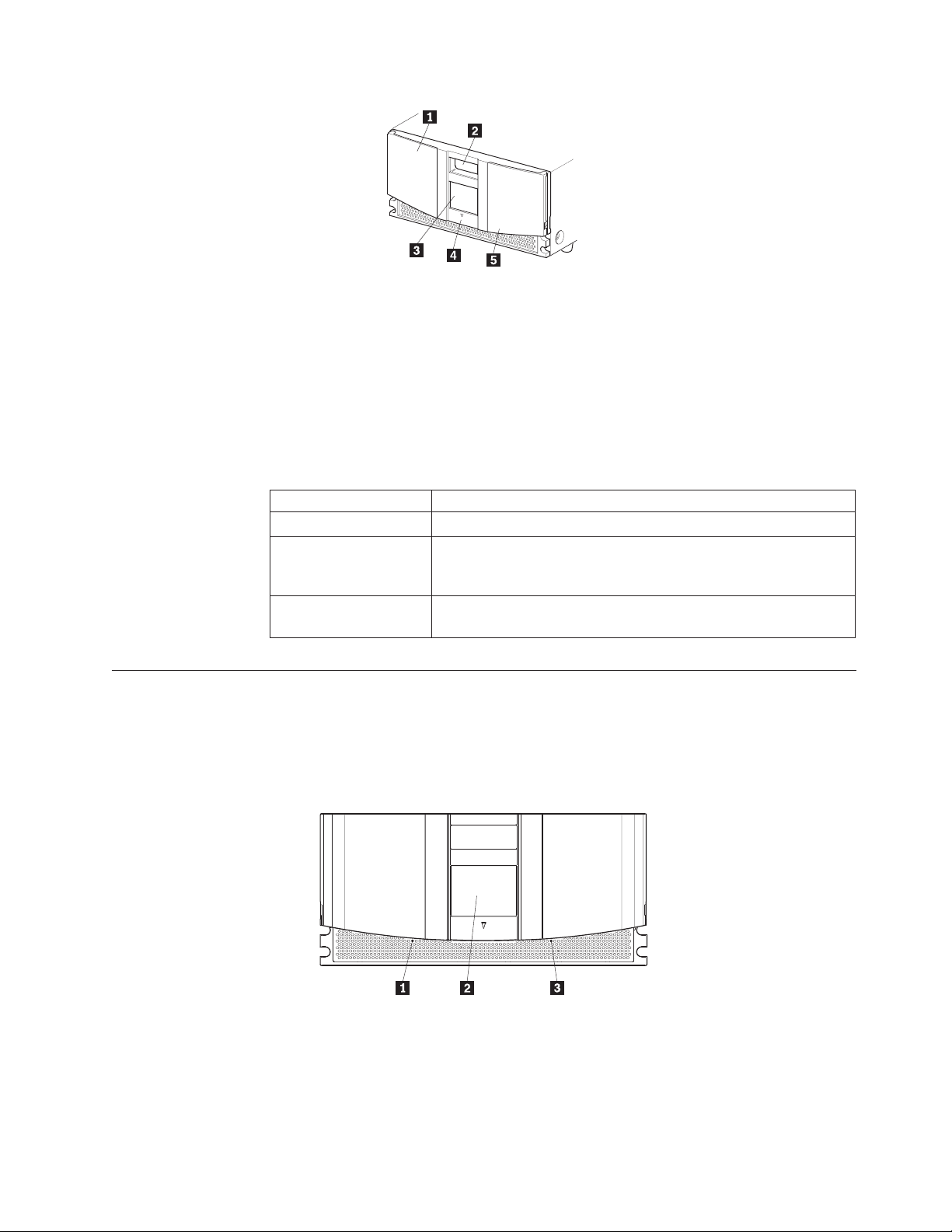
1 Left magazine door
2 Internal viewing window
3 Touch screen
4 Library status LED
5 Right magazine door
Figure 1. Library front panel
Table 1 describes the different indicator settings of the library status LED.
Magazine doors
The magazine doors have an electrical release on the touch screen and a manual
release (1 and 3 in Figure 2). Always open the doors using the touch screen. In
an emergency, the doors can be manually opened by pushing in on the mechanical
releases directly behind the front panel.
Table 1. Library front panel indicators
Library Indicators
Solid Green The library is operating correctly under normal conditions.
Flashing Green The library is operating correctly. However, a change is being
made through the touch screen that is interrupting the current
library operation.
Solid Amber The library is in a fault state as indicated by the fault message on
the touch screen.
1 Left magazine door release
2 Touch screen
3 Right magazine door release
Figure 2. Magazine door mechanical release
Chapter 1. Introduction 3
Page 14
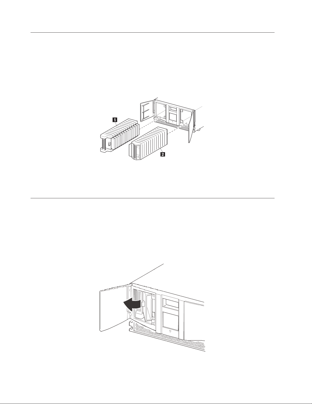
Magazines
The 4560SLX Tape Library contains two removable tape cartridge magazines that
are accessible through the magazine doors as shown in Figure 3. The magazine
doors are opened using the touch screen.
Note: The magazine must match the installed tape drive. For example, an LTO
magazine should be installed on an LTO drive and an SDLT magazine
should be installed on an SDLT drive.
1 Left magazine with integrated mail slot
2 Right magazine
Figure 3. Magazines
Mail slots
As viewed from the front of the 4560SLX Tape Library, the left tape magazine
includes a mail slot, which is accessible when the left magazine slot door is open as
shown in Figure 4. This mail slot enables you to insert or remove a single media
cartridge without interrupting library operation. If a full tape cartridge magazine is
required, you can configure the library to disable the mail slot feature. The right
tape magazine contains fixed cartridge slots (no mail slot feature), so it retains its
full capacity at all times.
Figure 4. Mail slot
4 4560SLX Tape Library: User’s Guide
Page 15
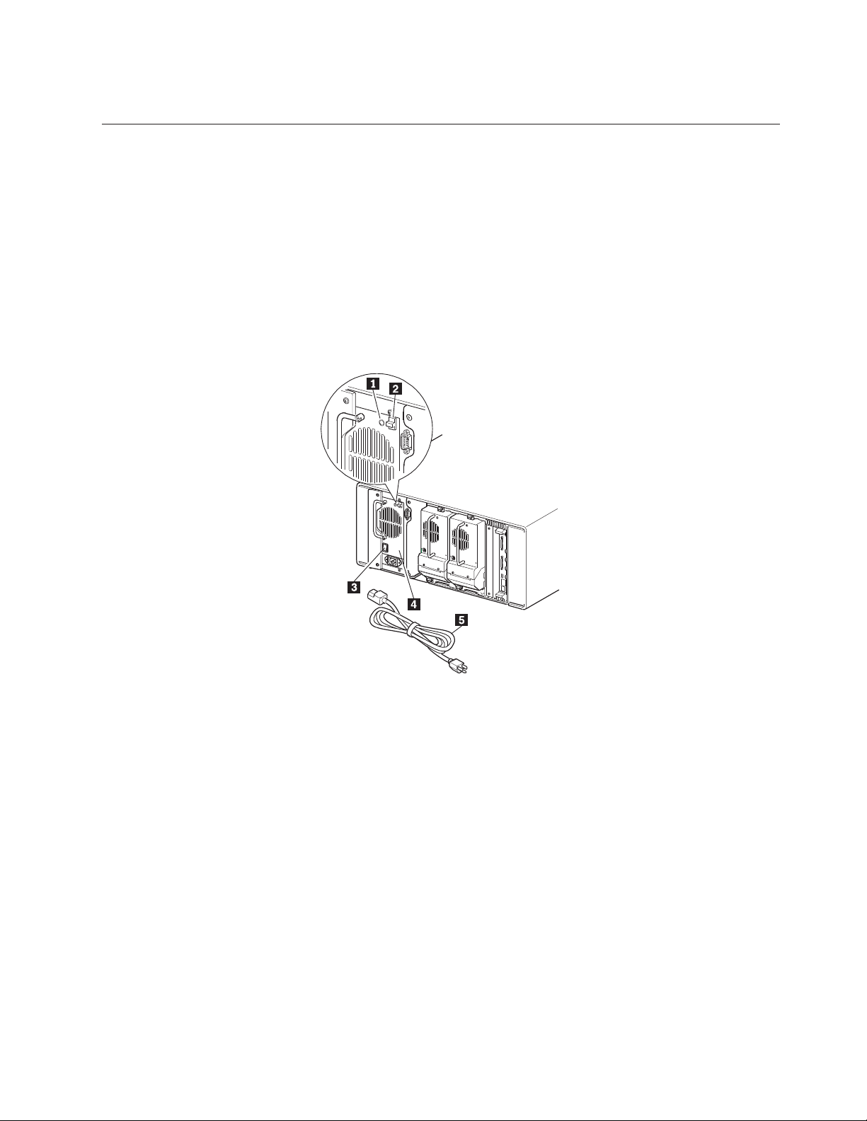
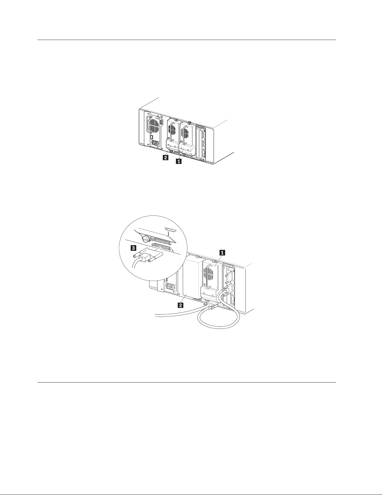
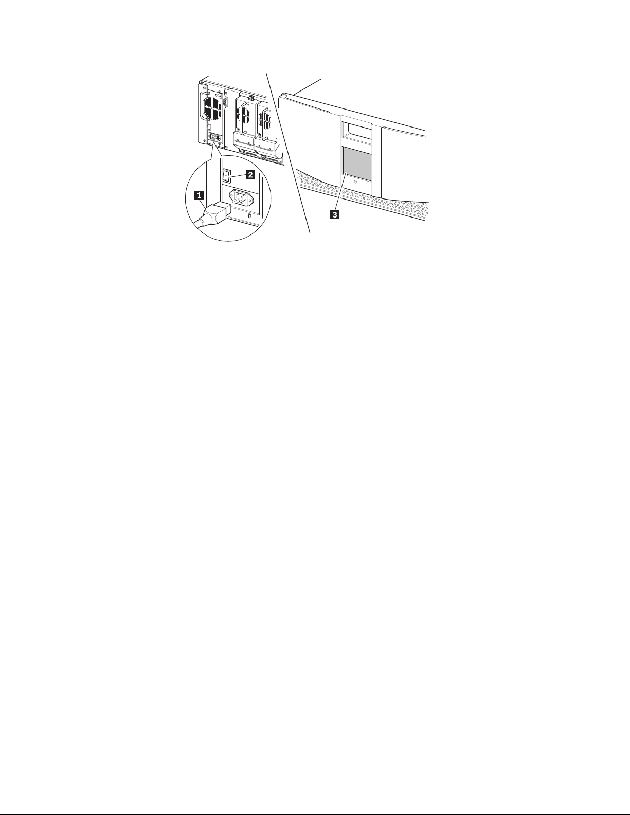
Power supply
The power supply is accessible from the rear of the library as shown in Figure 5.
These auto-ranging power supplies are capable of using any nominal ac voltage
between 100 and 240 V power at 50 Hz or 60 Hz.
Power to the library is supplied through the cord on the rear panel of the power
supply. Library power is controlled from the touch screen. However, a manual
power disconnect switch, located on the rear of the power supply, can also be
used.
Note: Only trained service personnel should remove the power supply. Hazardous
voltage is present in the cavity if the power cord is removed.
1 Power on LED (lights after touching the touch screen)
2 Power supply release latch
3 Power switch
4 Power supply
5 Power cord
Figure 5. Power supply
Chapter 1. Introduction 5
Page 16
Tape drives
The 4560SLX Tape Library supports a 0-drive, 1-drive, or 2-drive configuration as
shown in Figure 6. All inactive tape drives are hot-swap capable. SCSI I/O is
accomplished through two VHDCI-series 68-pin SCSI connectors located on the
rear of the library directly under each tape drive as shown in Figure 7.
1 Tape drive 1
2 Tape drive 2
Figure 6. Tape drive locations
1 Drive 1
2 Drive 2 bay
3 VHDCI 68-pin connectors
Figure 7. Tape drive connectors
Library controller board
The library contains a rear-access adapter cage (see Figure 8 on page 7) and a PCI
backplane. This backplane contains the plug-in connectors for the library controller
board and FCO card.
6 4560SLX Tape Library: User’s Guide
Page 17
1 Rear access card cage
2 Library controller board
Figure 8. Library controller adapter and PCI slots
The library controller board contains a single microprocessor and associated logic
devices to control all robotics operations and manage overall library functions. The
microprocessor enables the SCSI interface between the library and the host system,
including Web TLC (Total Library Control).
Web TLC is built into the library controller board. Web TLC enables you to
remotely monitor and control the tape library from any terminal on a local
network or access the internet. For more information on Web TLC, see Chapter 8,
“Web TLC” on page 63.
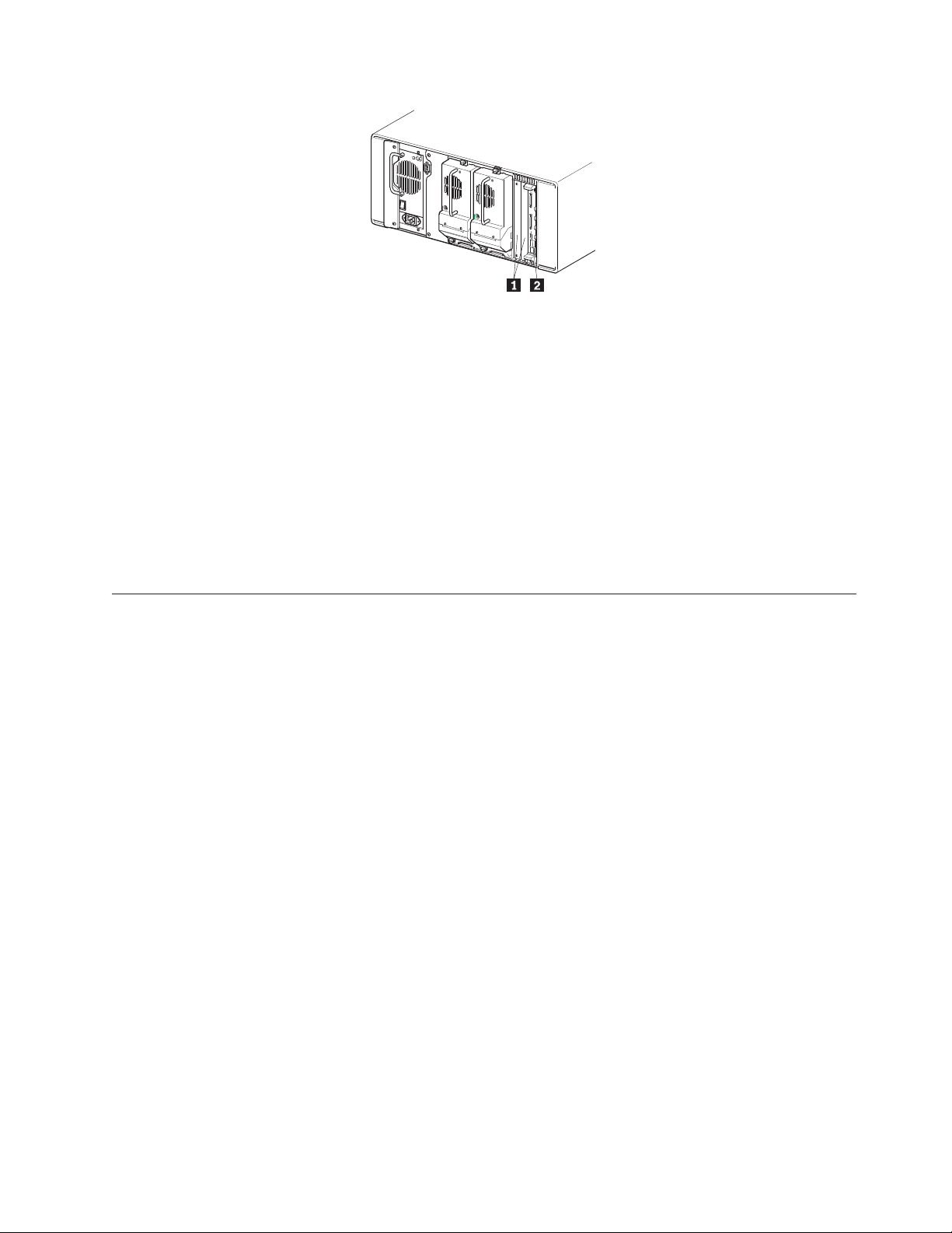
Robotics
The library contains robotics which consist of a cartridge shuttle, motor hardware,
motor drives, and other support electronics. The robotics can pick up and place
tapes throughout a 180° arc that consists of the tape drives, tape cartridge
magazines, and an optional cartridge elevator.
The cartridge shuttle assembly includes a mounted bar code reader for scanning
tape cartridges installed in the magazines and tape drives as shown in Figure 9 on
page 8.
A full bar code reader scan and a physical scan are conducted each time the library
is powered up or a tape magazine is exchanged.
Chapter 1. Introduction 7
Page 18
1 Bar code reader
2 Cartridge shuttle assembly
Figure 9. Library robotics
Multi-module library systems
The 4560SLX Tape Library is an expandable tape library that can be configured in
a variety of module and drive combinations. The drives are mounted in a
removable drive shoe that enables easy installation and removal. Therefore, a failed
drive can be swapped without the server or library power needing to be cycled.
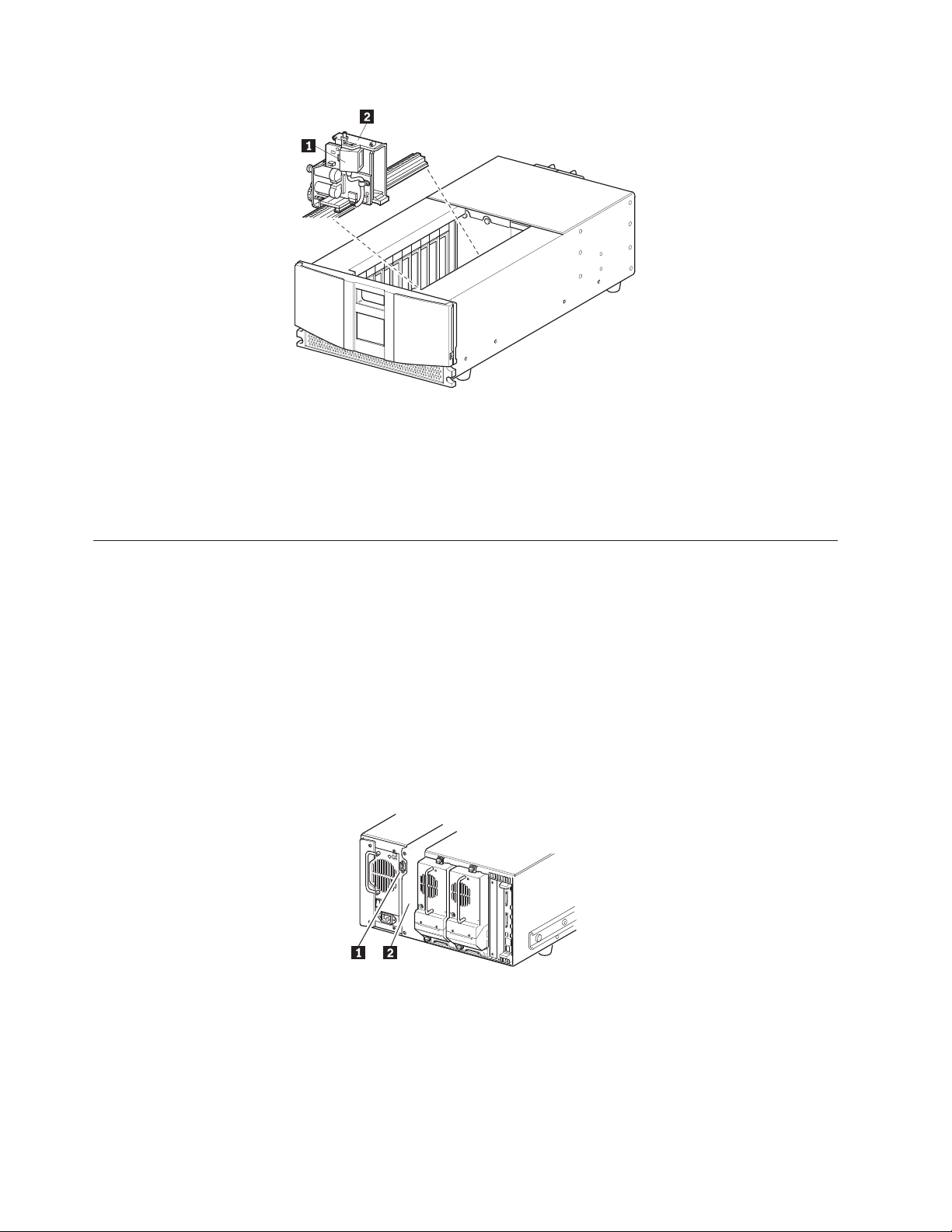
The library can be stacked with additional library modules to form a
multi-module, rack-mounted configuration. All multi-module libraries in the stack
can operate together as a single virtual library system through a rear-mounted
cartridge elevator as shown in Figure 10. Stacked units are interconnected through
their rear panel Ethernet connections and an external Ethernet router mounted to
the rack.
1 Interface connector
2 Cartridge elevator location
Figure 10. Cartridge elevator mounting location and connector
Any combination of modules, not exceeding a height of 40U can comprise a library
module system. A library module system appears to the host computer system and
8 4560SLX Tape Library: User’s Guide
Page 19

library control software as a single library. For multi-module applications, the top
library module becomes the primary master module and all other libraries become
slave modules.
The library robotics pick up and place tape cartridges into an elevator so that
individual tapes can be passed up or down between libraries in a multi-unit
library configuration.
The 4560SLX Tape Library supports fail-over protection for multi-unit library
configurations. In the event of a master module failure, a pre-selected slave
module can become the fail over master. For example, if the primary master library
fails, you can invoke the library system fail-over mode. In this mode, one of the
connected slave units serves as the secondary master library, communicating with
the host system through the SCSI interface. The source of power to the cartridge
elevator drive motor is switched from the original primary master library to the
newly-assigned secondary master library.
Chapter 1. Introduction 9
Page 20

10 4560SLX Tape Library: User’s Guide
Page 21
Chapter 2. Installation
This chapter explains how to install the 4560SLX Tape Library. Sections in this
chapter include:
v Setup
v SCSI cable configurations
v Turning on the library
Setup
Before rack mounting the library, make sure there is adequate space available in
the rack. See “Installation considerations” on page 96, for considerations relating to
multi-unit rack-mounted environments.
Note: When lifting the library use a mechanical lifter or a two person minimum.
Statement 4
CAUTION:
≥18 kg (37 lbs) ≥32 kg (70.5 lbs) ≥55 kg (121.2 lbs)
Use safe practices when lifting.
Figure 11 on page 12 identifies the parts needed for a rack-mount installation.
© Copyright IBM Corp. 2002 11
Page 22
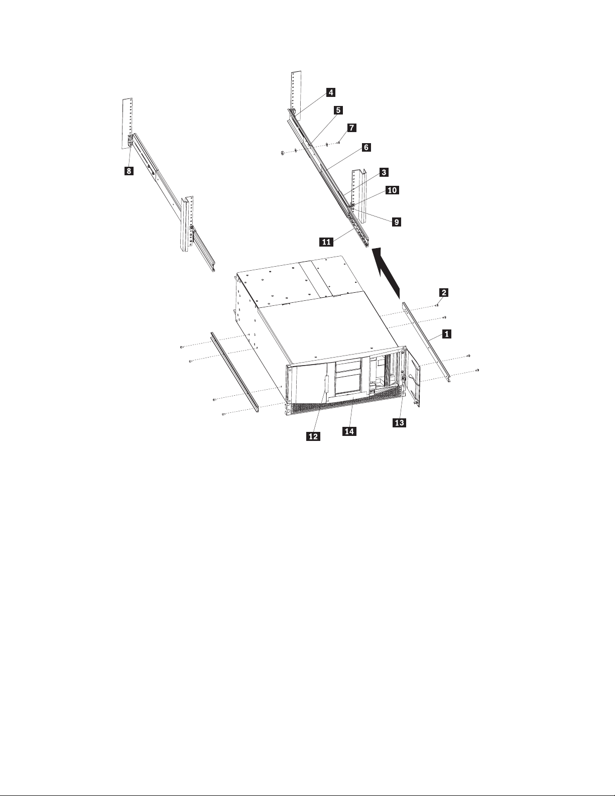
1 Inner slide member 8 Clip or cage nut (eight 8-32)
2 Hex screw (eight M4 x 8mm) 9 Screw (eight 10-32 x 5/8)
3 Front mounting bracket 10 Clip or cage nut (two 10-32)
4 Rear mounting bracket 11 Ball bearing slide member
5 Outer slide member 12 Sticker
6 Middle slide member 13 Thumbscrew (two 10-32)
7 Screw, flat washer, lock washer, nut (eight sets) 14 Door latch insert
Note: If you are installing the library on the IBM Netbay42 Enterprise rack, clip nuts (8 and 10) are provided. If
you are installing a Netbay11, Netbay25, or Netbay42 standard rack, cage nuts are provided.
Figure 11. Rack mounting the library
Attaching the slide members to the library
To attach the slide members to the library, complete the following procedures:
1. Remove the inner slide member (1) from each rack-mount slide.
2. Attach the inner slide members to the sides of the chassis using eight hex
screws (2).
12 4560SLX Tape Library: User’s Guide
Page 23
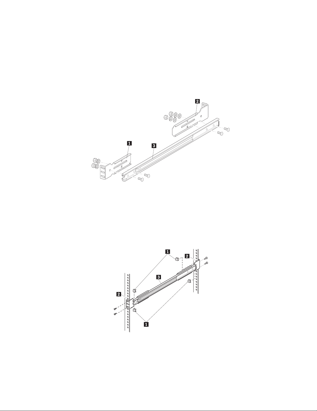
Attaching the slide members to the rack
To attach the slide members to the rack, complete the following procedure:
1. Attach the front (shorter) and rear (longer) mounting brackets to the outer and
middle slide members as shown in Figure 12.
IMPORTANT: Fully tighten the front mounting bracket screws. Leave the rear
mounting bracket screws “finger tight” to prevent binding when mounting the
library module. Once the distance between rails is set, the screws should be
fully tightened.
1 Front mounting bracket
2 Rear mounting bracket
3 Middle slide member
Figure 12. Installing the slide members
2. Depending on the type of rack you are installing, use the clip or cage nuts to
attach the slide member assembly to the rack as shown in Figure 13.
1 Clip or cage nuts
2 Vertical member mounting holes
3 Middle slide member
Figure 13. Installing slide member fasteners
Chapter 2. Installation 13
Page 24
3. Push the middle slide member as far as possible to the front of the slide
member assembly.
Installing a library in the rack
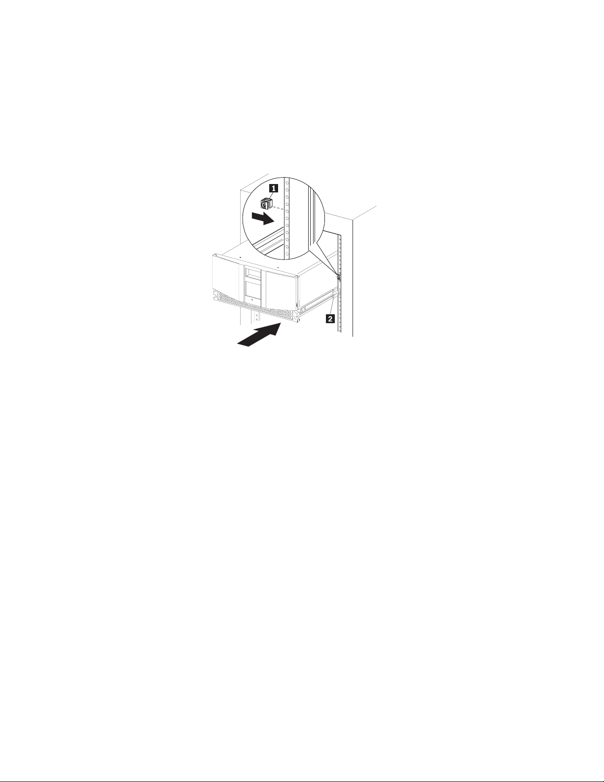
To install a library in the rack, complete the following procedure:
1. Install a clip or cage nut on each side of the front vertical rails as shown in
Figure 14.
1 Clip or cage nut
2 Vertical member mounting holes
Figure 14. Installing the library module
2. Lighten the library module by removing the drives.
3. Lift the library and visually align the inner and middle slide members. (It is
good practice to use a mechanical lifter to lift the library.)
4. Carefully insert the chassis inner slide members into the extended
rack-mounted middle slide members. Ensure that the ball bearing slide
members are located in the front position.
5. Slide the library completely into the rack until the front panel touches the
rack.
6. Remove the stickers that hold the doors in a closed position.
7. With the doors open, attach the library to the rack using two 10-32 captive
thumbscrews (located on the front panel inside the front doors). (See 1 and
2 in Figure 15 on page 15.)
14 4560SLX Tape Library: User’s Guide
Page 25
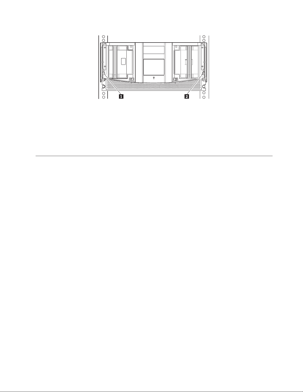
Figure 15. Retaining screws
8. Remove the door latch insert (the red tab located on the front panel).
9. Re-insert the drives.
10. Fully tighten the rear mounting bracket screws.
11. Close the doors.
12. Connect the ac power supply to the library.
SCSI cable configurations
The 4560SLX Tape Library supports multiple SCSI cable configurations on single
and dual host systems.
SCSI interface connectors
The library should be attached to a low voltage differential SCSI bus. Each tape
drive in the library and its robotics is a separate SCSI device. When two or more
devices are connected to the same SCSI bus, each SCSI device must be assigned a
unique SCSI ID. For information on assigning SCSI IDs, see “Setting a SCSI ID” on
page 21.
To connect a library to a host system, the host system must have at least one wide
LVD controller and the appropriate device driver software.
Interface cable specifications
The library is a high-performance system. To avoid degradation of performance,
use the highest quality interface cables from a reputable manufacturer of computer
cables. All SCSI cables used with the library should meet the following cable
specifications:
v Shielded or double-shielded as required to meet EMI specifications
v Impedance match with cable terminators that meet current SCSI specifications
v Characteristic impedance 115 ohms
All SCSI cables used with the library should meet the following usage guidelines:
v Each end of a twisted pair ground connected to chassis ground
v Maximum cable length of 39 ft. (12 m) for an LVD SCSI bus
v Cables of different impedances should not be used together
Additional specifications to ensure the highest SCSI performance can be found in
the current version of ANSI X3.131.
Chapter 2. Installation 15
Page 26
SCSI configuration
Your specific configuration will depend on the speed of your host and SCSI
controller. The library uses high performance tape drives. The tape drive
performance might be degraded if you attach too many drives to a single SCSI
host controller.
One tape drive on a single host system
Figure 16 shows a typical SCSI cable configuration for a library with one tape drive
(drive 1) installed.
1 SCSI terminator
2 To library controller card
3 To host system
Figure 16. One tape drive single host
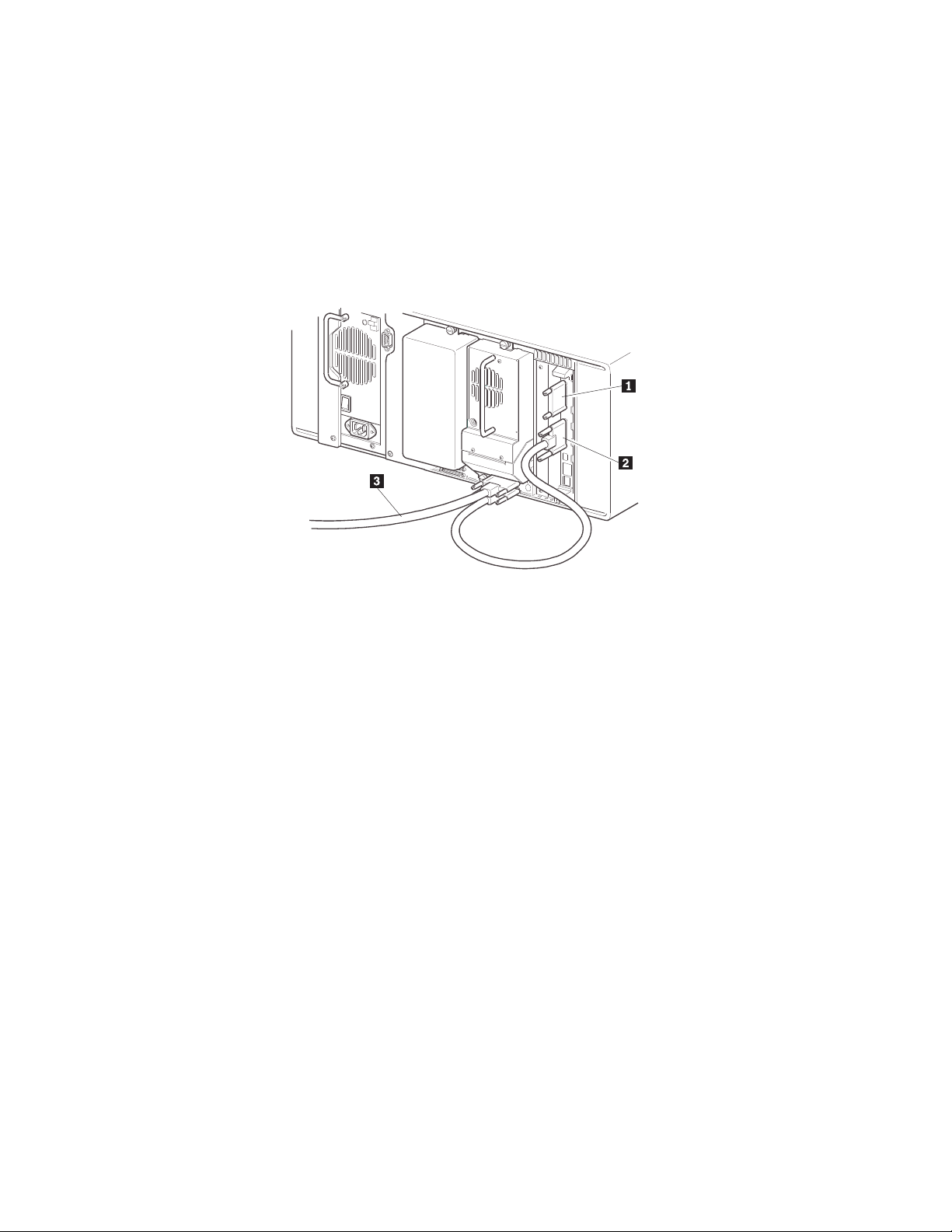
Two tape drives on a single host system
Figure 17 on page 17 shows a typical SCSI cable configuration for a library with
two tape drives installed using a single host system.
16 4560SLX Tape Library: User’s Guide
Page 27
1 SCSI terminator 3 Jumper cable
2 To library controller card 4 To host system
Figure 17. Two tape drives single host
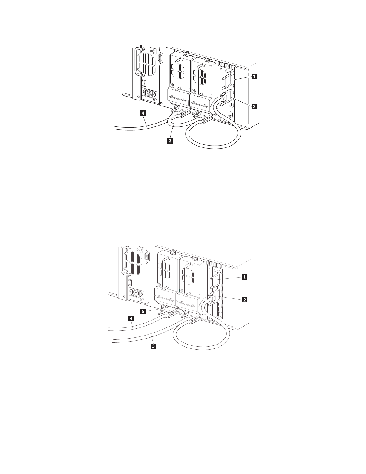
Two tape drives on a dual host system
Figure 18 shows a typical SCSI cable configuration for a library with two tape
drives installed using a dual host system.
1 SCSI terminator 4 To host (drive 2)
2 To library controller card 5 SCSI terminator
3 To host (drive 1)
Figure 18. Two tape drives dual host
Chapter 2. Installation 17
Page 28
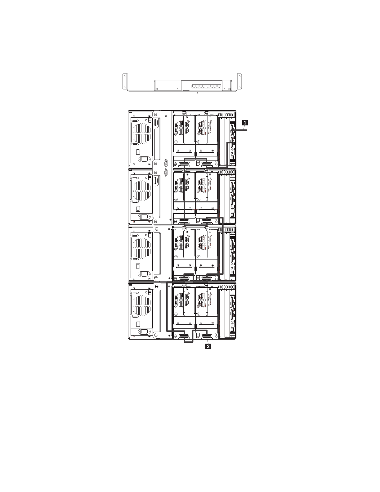
Multiple libraries on a single host system
Figure 19 shows a typical SCSI cable configuration for a multi-unit library with a
varying number of drives using a single host system.
WAN
567
432
1
1 To host system
2 SCSI terminator
Figure 19. Single host multi-unit system
18 4560SLX Tape Library: User’s Guide
Page 29
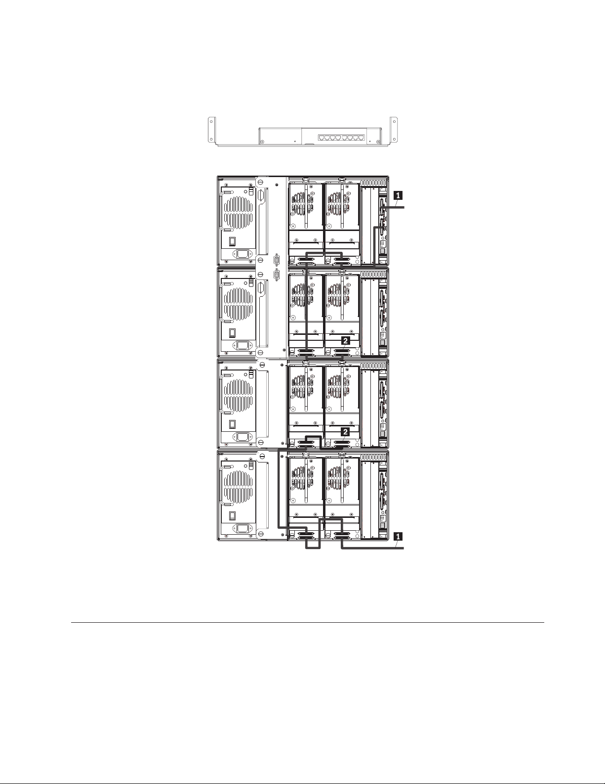
Multiple libraries on a dual host system
Figure 20 shows a typical SCSI cable configuration for a library with multiple
libraries and tape drives installed using a dual host system.
WAN
567
432
1
1 To host system
2 SCSI terminators
Figure 20. Dual host multi-unit system
Turning on your library
Use the following instructions to apply power to the library:
1. Connect the supplied power cord to the ac receptacle located on the back of the
library module as shown in Figure 21 on page 20.
Chapter 2. Installation 19
Page 30
1 Power cord
2 Power switch
3 Touch screen
Figure 21. Powering library module
2. Toggle the power switch to on “|”.
3. Press the touch screen to activate the display.
When power is first applied to the libraries, a series of Power-On Self Test
(POST) diagnostics are performed. After the POST completes, the Initialization
screen will appear.
4. Select Continue.
The library default screen will display.
20 4560SLX Tape Library: User’s Guide
Page 31

Chapter 3. Library configuration
The library provides several configuration options to support a variety of
applications and platforms. The settings for each of the available options are stored
in non-volatile memory in the library. For most applications, you do not have to
change the default settings. However, if you need to change the configuration, use
the instructions provided in the following sections. If you are uncertain whether
you need to change a setting, contact your authorized service provider.
You can change configuration settings using the touch screen. For information on
operating the touch screen, see Chapter 4, “Operation” on page 27.
Setting a SCSI ID
Each tape drive installed in the library requires a unique SCSI ID.
To set a SCSI ID, complete the following procedure:
1. Turn the library on and wait until the Power-On Self Test (POST) completes.
The library default screen appears on the display as shown in Figure 22.
Figure 22. Library default screen
2. Select the Menu option.
3. Enter the appropriate password. For instructions on how to set passwords, see
“Passwords” on page 38.
4. Select SCSI in the Edit Options area to display the screen shown in Figure 23
on page 22.
© Copyright IBM Corp. 2002 21
Page 32

Figure 23. SCSI ID selection screen
5. Select the button next to the SCSI ID you want to set. The screen will display
the current setting as shown in Figure 24.
Figure 24. SCSI ID editing screen
6. Enter a new value for the SCSI ID. This places your request in the New data
field.
7. Select Save. A confirmation screen appears on the display as shown in
Figure 25.
Figure 25. SCSI ID Confirmation screen
8. Select OK to confirm. The newly selected SCSI ID flashes for a few seconds
while the drive is being updated, then remains solid indicating that the
operation is complete.
22 4560SLX Tape Library: User’s Guide
Page 33

Figure 26. Drive 1 Bus 3 Data Field screen
9. Press the Back button to return to the Main menu screen. Repeat this procedure
to set any remaining SCSI IDs.
Setting up reserved tape cartridge slots
You might want to reserve tape cartridge slots to meet licensing requirements or
dedicate them as cleaning slots.
Standard tape cartridge slots are numbered from the front of the magazine to the
rear as shown in Figure 27 on page 24. When you reserve a slot, it becomes
reserved slot #1 in the last slot of the magazine. Additional reserved slots are
added in a rear-to-front pattern. If your software license limits you to less than the
full magazine capacity, reserved slot #1 always follows the last unreserved data
tape cartridge.
Chapter 3. Library configuration 23
Page 34

1 Reserved slot #1
2 Mail slot (left magazine only)
Figure 27. Slot numbering
#12
#11
#10
#9
#8
#7
#6
#5
#4
#3
#2
#1
MAIL SLOT
#25
#24
#23
#22
#21
#20
#19
#18
#17
#16
#15
#14
#13
To reserve a slot, complete the following procedure:
1. From the Menu screen, select the Library option from the Edit Options area.
2. From the Library options screen, press the down arrow to scroll to the screen
that contains the Total Reserved Slots option as shown in Figure 28.
Figure 28. Total Reserved Slots screen
3. Press the box next to the Total Reserved Slots option. A numeric keypad
appears on the display as shown in Figure 29 on page 25.
24 4560SLX Tape Library: User’s Guide
Page 35

Figure 29. Reserved slots numeric keypad
4. Enter a new value and select Save. A confirmation screen appears on the
display as shown in Figure 30.
Figure 30. Total Reserved Slots Confirmation screen
5. Press the Back button until you return to the Main menu screen. Your change
will take effect the next time you boot the library.
Chapter 3. Library configuration 25
Page 36

26 4560SLX Tape Library: User’s Guide
Page 37

Chapter 4. Operation
This chapter describes how to operate the 4560SLX Tape Library.
Using the touch screen
The touch screen enables you to set up and configure the library. This section
describes the following options that are available from the library default screen:
v Technical support information
v Mail slot access
v Magazine access
v Move media
v LCD contrast control
v Menu
v Online
v Status
v Power
Technical support information
Select the Contact IBM button on the top left corner of the library default screen to
display technical support information as shown in Figure 31.
Figure 31. Technical Support Assistance screen
Mail Slot Access (left magazine only)
Select this option to display the Mail Slot Access screen as shown in Figure 32 on
page 28. This option enables you to access the mail slot while the library is online.
Simply select the mail slot you want to open. The locked icon will change to
unlocked and the left side door of the selected library will open.
The mail slot is always the first tape cartridge slot in the left magazine. It can be
password protected.
© Copyright IBM Corp. 2002 27
Page 38

Figure 32. Mail Slot Access screen
Note: In a scaled multi-module library system, selecting the Mail Slot Access
button on the master library touch screen displays the mail slots of all the
libraries in the stack. This is the only way to access the mailslots of the other
libraries.
Magazine Access
Select this option to display the Magazine Access screen as shown in Figure 33.
The Magazine Access option enables you to access the magazine doors for tape
cartridge placement or removal. Access is gained by selecting the library you want
to access and then selecting left, right, or both. The lock icons will change to
unlocked and the doors of the selected library will open.
Magazine access can be password protected.
Figure 33. Magazine Access screen
Note: In a scaled multi-module library system, selecting the Magazine Access
button on the master library touch screen is the only way to access the left
and right magazines of all libraries in the stack.
Move Media
Select this option to display the Move Media screen as shown in Figure 34 on
page 29. The Move Media option enables you to remove cartridges from a tape
drive, load cartridges into a drive, or move cartridges within the library.
28 4560SLX Tape Library: User’s Guide
Page 39

Figure 34. Move Media screen
To move a cartridge, complete the following procedure:
1. Touch the Source box or Source Element Type from the Move Media screen.
The Source box will change from gray to an active state as shown in Figure 35.
Figure 35. Move Media screen (source)
2. From the Source Element Type area, select the element type you want to move.
Drive 2 is used for this example.
3. Touch the Destination box on the Move Media screen. The Destination box
will change from gray to an active state as shown in Figure 36.
Figure 36. Move Media screen (destination)
4. From the Destination Element Type area, select the element type you want to
move media to. Continue selecting the destination option until the desired
Chapter 4. Operation 29
Page 40

option is displayed in the Destination box. For example, touching Slot three
times displays Slot 3 in the Destination box.
5. Select the Execute Move button. The library robotics moves the cartridge to the
destination you selected.
LCD contrast controls
This option enables you to increase or decrease the contrast of the LCD display.
Incremental steps are set by adjusting the LCD contrast controls using the up and
down arrows from the upper right corner of the library default screen.
Menu
Select Menu on the library default screen to operate and configure the library.
Figure 37 shows the Menu option interface which displays three distinct areas:
v View System Data
v Utilities
v Edit Options
Figure 37. Menu screen
View System Data
The View System Data area enables you to view the following information:
v Library options
v SCSI options
v Network options
v Library information
v Cartridge map
Library Options: This option enables you to view, but not modify, the library
settings as defined in the Library option of the Edit Options area as shown in
Figure 38 on page 31. For descriptions of the available options, see Table 2.
Note: You can view the next sequential Library Options screen by selecting the
down arrow. To return to the Menu screen, press the Back button.
30 4560SLX Tape Library: User’s Guide
Page 41

Figure 38. View Library Options screen (initial screen)
Table 2 describes the available Library options.
Table 2. Library options
Option Description
Library Stays Offline After
Power-up Initialization
Auto Power-up an Installed
Drive
Unload Mode This option selects the unload mode for library tape drives.
Total Reserved Slots This option enables you to remove a specified number of
Auto Clean Mode This option enables you to establish an automatic cleaning
Drive and Slot Numbering This option enables you to specify SCSI elements in the
Library Mode This option enables you to set the robotics operating mode
Sequential Mode This option enables you to select a normal or recirculate
LCD Contrast Adjust This option enables you to increase or decrease the contrast
Mail Slot Mode This option enables the mail slots in a library. The default is
The library does not go online after power-up initialization.
You must select the online option from the menu screen on
the touch screen. The default is disabled.
This option enables a tape drive to be automatically
powered up after replacing a tape drive. The default is
disabled.
If the mode is implicit, the library unloads a tape drive
before attempting to move a cartridge from that tape drive.
If the mode is explicit, the host must issue a SCSI
UNLOAD command to a tape drive before each MOVE
MEDIUM command that removes a cartridge from that tape
drive. The default is implicit.
slots from use. Some host software impose size limits on
library magazines for licensing purposes. The default is 0.
cycle. To use this option, reserve a slot for a cleaning
cartridge using the Total Reserved Slots option. The default
is enabled.
library displayed as zero-based or one-based numbers. This
only affects the touch screen, not the actual SCSI addresses.
The default is one-based.
to random or sequential. The default is random.
frequency mode. The default is normal.
Note: This is only available if Library Mode is set to
sequential.
of the LCD display.
mail slot enabled.
Chapter 4. Operation 31
Page 42

Table 2. Library options (continued)
Option Description
Barcode Label Size This option enables you to limit the maximum number of
characters of the bar code label. Possible settings are 1
through 8. The default is 8.
Barcode Label Alignment This option enables you to specify the alignment of a bar
code label. The options are left or right. When used in
conjunction with the label size option, this option strips
unwanted trailing characters (left alignment) or leading
characters (right alignment). The default is left align.
Barcode Label Check Digit This option enables you to specify whether to enable or
disable the verification of a check digit character in the
barcode label. The default is disabled.
Barcode Reader This option enables you to specify whether the barcode
reader will retry reading barcode labels. The default is
retries enabled.
Module Configuration This option enables you to specify the library module
configuration. Three options are available:
v Standalone - This option is used when the library
contains a single module.
v Master - This option is used to select the module which
controls the pass-thru mechanism in a multi-module
library.
v Slave - This option is used to select the other modules in
a multi-module library.
SCSI Options: This option enables you to view the settings defined from the SCSI
option in the Edit Options area as shown in Figure 39.
Figure 39. View SCSI Options screen (initial screen)
Table 3 describes the available SCSI options.
Table 3. SCSI configuration options
Definition Option and default description Default value
Drive n Bus ID This option enables you to set the SCSI addresses of
the drives. The designators Drive 1 (outer tape
drive) through Drive n refer to the first through nth
drives. (one based default)
Library SCSI BusIDThis option enables you to set the SCSI addresses
for the library robotics.
Drive1=1
Drive2=2
6
32 4560SLX Tape Library: User’s Guide
Page 43

Table 3. SCSI configuration options (continued)
Definition Option and default description Default value
Library SCSI Bus
Parity
This option enables you to set the library robotics
SCSI bus parity checking.
Enabled
SCSI Mode This option defines the loader as SCSI-2 or SCSI-3. SCSI-3
Mailslot access This option defines when the mailslot is accessible. Prevent/Allow
Medium
Command
Determines
Access
Unit Attention
Reporting
This option enables you to select reporting of all or
only one stacked-unit attention conditions. If set to
Report All
all, the unit reports all unit attention conditions in
sequence. If set to one, the unit reports only the
highest priority condition.
Init Element Status This option enables you to specify the library
No Inventory
response to the SCSI INITIALIZE ELEMENT
STATUS command. The possible settings are no
inventory, force inventory, and force label scan.
Test Unit Ready
Reporting
This option enables you to specify the response to a
TEST UNIT READY command if the library is in
Standard
sequential mode. The possible settings are standard
or custom. Standard returns check condition not
ready and custom returns good status.
Device Capability
Page Length
This option enables you to choose between two
lengths of the mode sense/select device capabilities
Short (14 bytes)
page (SCSI page 1Fh), which are short (14 bytes)
and long (18 bytes), to accommodate different SCSI
device implementations of this page.
Transport Element
Base Address
Storage Element
Base Address
Transfer Element
Base Address
Import/Export
Element Base
This option enables you to set the base address for
the robotics mechanism.
This option enables you to set the base address for
the magazine slots.
This option enables you to set the base address for
the tape drives.
This option enables you to set the base address for
the mail slot.
0
20
1E0
1C0
Address
Product
Identification
This option enables you to specify the response of
the library robotics to the SCSI INQUIRY command
4560SLX
in the product ID fields.
Vendor
Identification
This option enables you to specify the response of
the library robotics to the SCSI INQUIRY command
IBM
in the vendor ID field.
Post Recovered
Errors
This option enables you to set the post recovered
errors.
Disabled
Chapter 4. Operation 33
Page 44

Table 3. SCSI configuration options (continued)
Definition Option and default description Default value
TapeAlert Mode This option enables you to specify the conditions
for logging and reporting the following tape alert
data options:
v Logging Disabled: Inhibits the logging feature.
v No Exceptions: Prohibits the library from
reporting information exceptions.
v Generate Unit Attention: Reports information
exceptions with a Unit Attention sense key and
an ASC/ASCQ of 5D/00.
v Conditionally Generate Recovered Error:
Reports information exceptions with a Recovered
Error sense key and an ASC/ASCQ of 5D/00, if
Recovered Error Reporting is enabled.
v Unconditionally Generate Recovered Error:
Reports information exceptions unconditionally
with a Recovered Error sense key and an
ASC/ASCQ of 5D/00.
v Generate No Sense: Reports information
exceptions with a No Sense sense key and an
ASC/ASCQ of 5D/00.
v Report on Unsolicited Request Sense: Reports
information exceptions with a No Sense sense
key and an ASC/ASCQ of 5D/00, only in
response to an unsolicited REQUEST SENSE
command.
Abort Move Status This option enables you to specify the SCSI
response while aborting a SCSI command. The
possible settings are busy or not ready.
Door Open
Response
Initiate Wide Data
Transfer
Negotiation
Data Speed
Transfer
This option enables you to specify the SCSI
response when a library door is open. The settings
are ready or not ready.
This option enables you to set the library to initiate
a SCSI synchronous and wide data transfer
negotiation with the host. The settings are do not
initiate or initiate.
This option enables you to set the SCSI data
transfer rate to Synchronous, 10 MB/sec, 5 MB/sec
or Asynchronous Only.
Logging
Disabled
Busy
Not Ready
Initiate
Synchronous, 10
MB/sec
Network Options: This option enables you to view the settings defined in the
Network option in the Edit Options area as shown in Figure 40 on page 35.
34 4560SLX Tape Library: User’s Guide
Page 45

Figure 40. View Network Options screen
Table 4 describes the available Network options.
Table 4. Network configuration options
Definition Option and default description Default value
IP Address
Determination
Private IP Base
Address
Private IP Subnet This option enables you to specify a private IP
Private IP
Gateway
Note: These options are only valid if the IP Address Determination Option is set to User
Specified IP Address.
This option enables you to set the way an IP
address is determined. The possible choices are:
Obtain An IP Address From a DHCP Server and
User Specified IP Address.
This option enables you to specify a private IP base
address.
Note: Master configurations only; ignored
otherwise.
subnet.
Note: Master configurations only; ignored
otherwise.
This option enables you to specify a private IP
gateway.
Note: Master configurations only; ignored
otherwise.
Obtain An IP
Address From a
DHCP Server
92.168.1.1
255.255.255.0
192.168.1.1
Library Info: This option enables you to display miscellaneous library
information. The Miscellaneous Library Info screen displays the library firmware
revision, IP address, and the library serial number as shown in Figure 41 on
page 36.
Chapter 4. Operation 35
Page 46

Figure 41. View Library Info screen
Cartridge Map: This option provides a visual indication of all library drives, mail
slots and magazine slots, including whether there is a cartridge present and
corresponding barcode label, if available.
Figure 42. Cartridge map
Utilities
The Utilities area contains the following screens:
v Maintenance
v Diagnostics
v Factory
v Security Level
Maintenance: This option enables you to:
v Set slave defaults
v Reboot server
v Fail-over to secondary master
Diagnostics: This option enables you to select and run several self-diagnostic
library tests.
Factory: This option is for factory use only.
Security Level: This option enables you to set passwords for one of the four
available security levels as shown in Figure 43 on page 37.
36 4560SLX Tape Library: User’s Guide
Page 47

Figure 43. Security Level screen
Table 5. Security level options
Security level Access
User Level 1 Mail slot access only
User Level 2 Mail slot and magazine access only
Service User and Service menus
Factory User, Service, and Factory menus
Edit Options
The Edit Options area contains the following screens:
v Library
v SCSI
v Network
v Passwords
Library: This option enables you to define the library options used to configure
the library for your specific needs. Defined options can be viewed in the View
System Data area as shown in Figure 44. For a description of the available Library
options, see Table 2 on page 31.
Figure 44. Edit Library Options screen
SCSI: Select this option to define the SCSI options used to configure the library
for your specific needs as shown in Figure 45 on page 38. For a description of the
available SCSI options, see Table 3 on page 32.
Chapter 4. Operation 37
Page 48

Figure 45. Edit SCSI Options screen
Network: This option enables you to define the network options used to
configure the library for your specific needs as shown in Figure 46. For a
description of the available network options, see Table 4 on page 35.
Figure 46. Edit Network Options screen
Passwords: This option enables you to define the password options used to
configure the library for your specific needs as shown in Figure 47 on page 39.
The Password screen offers three levels of security.
v User level 1 - This is the lowest level, which allows users access to the mail slot.
v User level 2 - This level allows magazine access and allows users to move
media.
v Service - This is the highest level, which allows users access to the menu that
enables them to view and edit library and SCSI options.
38 4560SLX Tape Library: User’s Guide
Page 49

Figure 47. Edit Passwords Options screen
Each password is represented by four decimal digits that are stored in NVRAM
(non-volatile memory) in a range of 0001 to 9999. 0000 is used to disable password
verification for that level.
Enabling a password causes all disabled higher levels to also be enabled to that
value. As a result, prior to accessing a higher level operation, you are prompted
first to enter the higher level password. This prevents someone from entering an
unprotected Menu mode and changing the lower-level password to defeat it.
You can also use a higher level password to gain access to a lower level operation.
For example, you can use the Service password to access the Move Media
operation. This gives full access (without validating) to the service operations.
Media can also be locked by software running on the host. The library does not
provide a touch screen override for this command. Usually, exiting the host
software restores media access. In the event of host failure, you can restore media
access by cycling the library power. Procedures for locking and unlocking
magazine doors and media are described later in this chapter.
Online
This option enables you to place the library online or offline. By default the library
comes online after a power-up initialization.
Status
This option displays the Library Initialization screen. You can identify a tape drive
type and view physical tape drive status, tape drive cleaning information, and tape
cartridge information by opening the corresponding areas on the screen as shown
in Figure 48 on page 40.
Chapter 4. Operation 39
Page 50

Figure 48. Status screen
Power
This option initiates a library power-down operation. Figure 49 shows the
confirmation screen that is displayed when this option is selected. The library
moves the shuttle assembly to the parked position before powering down.
Figure 49. Power Down Initiation screen
Using tape cartridges
This section describes how to remove magazines, insert cartridges into a magazine,
use the mail slot, and use bar codes.
Removing magazines
A magazine must be removed from the library in order to replace tape cartridges.
Before you remove a magazine, make sure the slot you want to use is not already
reserved for a tape cartridge that is in a tape drive. The safest way to do this is to
unload all tape drives before removing a magazine. You can unload all the tape
drives either through your host system software or by using the Move Media
option on the library default screen.
You must manually remove the library magazines. To access the magazines, use
the Magazine Access Option Default screen. This option enables you to open the
left or right magazine doors separately or both magazine doors at the same time.
After opening the appropriate magazine door, pull the magazine out and away
from the library chassis as shown in Figure 50 on page 41.
40 4560SLX Tape Library: User’s Guide
Page 51

1 Left magazine
2 Right magazine
Figure 50. Removing tape cartridge magazines
Inserting cartridges into a magazine
A full magazine is shown in Figure 51. Note that the lowest numbered tape
cartridge slot is the one closest to the front of the magazine.
Insert tape cartridges so that the bar code labels are facing outward.
Note: Handle and store tape cartridges in a clean and dust-free environment.
1 Lowest numbered tape cartridge slot
2 Bar code label
3 Highest numbered tape cartridge slot
Figure 51. Tape magazine with tape cartridges installed
Using the mail slot (left magazines only)
The mail slot is used only with host system software that supports this feature.
The mail slot feature enables you to insert or remove a single tape without
removing the entire magazine. You access the mail slot using the Mail Slot Access
option from the library default screen. This option enables you to open the left
Chapter 4. Operation 41
Page 52

magazine door for mail slot access. After opening the left magazine door, pivot the
mail slot forward to insert a tape cartridge as shown in Figure 52.
IMPORTANT: The mail slot must be enabled (factory default) using the Mail Slot
Mode option from the Edit Library Options menu. For more information on
Library options, see Table 2 on page 31.
1 Mail slot
2 Tape cartridge
Figure 52. Left magazine mail slot
Bar code labels
Sample bar code labels are included with your purchase. Also included are
instructions on ordering additional labels. Figure 53 shows you how to install a bar
code label onto a tape cartridge.
Figure 53. Bar code label installation
42 4560SLX Tape Library: User’s Guide
SDLT LTO
Page 53

Chapter 5. Maintenance
This chapter describes how to replace and run cleaning cartridges in the 4560SLX
Tape Library.
Note: Only qualified service technicians should perform the other menu options
contained in the Maintenance submenu.
Supported media
IBM supports the following brands of data and cleaning cartridges:
v SDLT data cartridges
– IBM (Part number: 35L1119)
– Maxell (Part number: SDLT1/1800)
– Quantum (Part number: MR-SAMCL-01)
v SDLT cleaning cartridges
– IBM (Part number: 19P4357)
– Quantum (Part number: MR-SACCL-01)
v LTO data cartridges
– IBM (Part number: 08L9120)
– Fuji (Part number: 26120010)
– Maxell (Part number: LTOU1/100)
– Imation (Part number: 0-51122-41089-5)
v LTO cleaning cartridges
– IBM (Part number: 08L9124)
Note: This list can change as new media is introduced. For a current list of
supported brands of data and cleaning cartridges, search for ″supported
media″ on the http://www.pc.ibm.com/support IBM Web site.
Running a cleaning cartridge
You can manage the cleaning of the installed tape drives automatically by enabling
Auto Clean mode or manually by selecting the Clean Drive menu option from the
Maintenance submenu on the front panel display.
Note: It is good practice to run a cleaning cartridge using the Auto Clean Mode.
Automatically running a cleaning cartridge
You can configure the library to automatically run the cleaning cartridge. If a tape
drive needs cleaning, it sends a message to the library. This activates an automatic
cleaning cycle (if the cleaning cartridge slot has been reserved and Auto Clean
mode has been selected from the Options menu).
To automatically run a cleaning cartridge using Auto Clean mode, reserve a
cleaning cartridge slot and enable the Auto Clean mode.
© Copyright IBM Corp. 2002 43
Page 54

Manually running a cleaning cartridge
You can manually run a cleaning cartridge from three locations:
v The mail slot - Running a cleaning cartridge from this location does not require
a magazine to be removed, a data cartridge slot to be used, or a cleaning
cartridge slot to be reserved.
v A data cartridge slot - Running a cleaning cartridge from this location requires a
magazine to be removed so that a cleaning cartridge can be inserted in a data
cartridge slot.
v The cleaning slot - Running a cleaning cartridge from this location requires the
last data cartridge slot be reserved for exclusive use as a cleaning cartridge slot.
The advantage of this method is that the cleaning cartridge is stored in the
library and is always available for use. It only needs to be handled when it
needs to be replaced.
Running a cleaning cartridge from the mail slot
To run a cleaning cartridge from the mail slot, complete the following procedure:
1. Install a cleaning cartridge into the mail slot.
2. Select the Clean Drive menu option from the Maintenance submenu on the
Menu screen.
3. Select Source and then Mail Slot in the Element Type box.
4. Select Cleaning. If the default entry is not the tape drive to be cleaned, select
Drive in the Destination Element Type box to sequence through the available
tape drive choices. You can also use the keypad to enter the tape drive number.
5. Select Execute Clean when the source and destination entries are correct. When
the cleaning cycle completes, the library returns the cleaning cartridge to the
mail slot.
6. Select Mail Slot Access from the Status screen to remove the cleaning cartridge.
Running a cleaning cartridge from a data cartridge slot
To run a cleaning cartridge from a data cartridge slot, complete the following
procedure:
1. Install a cleaning cartridge into the appropriate data cartridge slot.
2. Select the Clean Drive menu option from the Maintenance submenu on the
Menu screen.
3. Select Source. If the default entry is not the slot with the cleaning cartridge,
select Slot in the Element Type box to sequence through the available cartridge
slots. You can also use the Decimal Keypad Backspace and Numeric Keys to
enter the slot number.
4. Select Cleaning. If the default entry is not the tape drive to be cleaned, select
Drive in the Destination Element Type box to sequence through the available
tape drive choices. You can also use the Decimal Keypad Backspace and
Numeric Keys to enter the tape drive number.
5. Select Execute Clean when the source and destination entries are correct. When
the cleaning cycle completes, the library returns the cleaning cartridge to the
data cartridge slot.
6. Select Magazine Access from the Status screen to remove the cleaning
cartridge.
Running a cleaning cartridge from the cleaning slot
To run a cleaning cartridge from the cleaning slot, complete the following
procedure:
44 4560SLX Tape Library: User’s Guide
Page 55

1. Reserve the cleaning cartridge slot. For more information, see “Setting up
reserved tape cartridge slots” on page 23.
2. Install a cleaning cartridge in the reserved slot.
3. Select the Clean Drive menu option from the Maintenance submenu on the
Menu screen. The Source window defaults to the cleaning slot (cleaning slot 0).
4. Select Cleaning. If the default entry is not the tape drive to be cleaned, select
Drive in the Destination Element Type box to sequence through the available
tape drive choices. You can also use the Decimal Keypad Backspace and
Numeric Keys to enter the tape drive number.
5. Select Execute Clean, when the destination entry is correct. When the cleaning
cycle completes, the library returns the cleaning cartridge to the cleaning
cartridge slot.
Replacing a cleaning cartridge in a reserved slot
When the cleaning cartridge has been exhausted, a message appears on the touch
screen indicating that the cleaning cartridge has expired. Examine the Status screen
to make sure that the cleaning cartridge has been unloaded from the tape drive. If
not, unload the cleaning cartridge using the Move Media menu option from the
Status screen.
A cleaning cartridge can be removed and replaced by removing the right magazine
or by using the mail slot.
Replacing a cleaning cartridge in the right magazine
To replace a cleaning cartridge in the right magazine, complete the following
procedure:
1. Select Magazine Access from the Status screen.
2. Remove the magazine from the library.
3. Remove the expired cleaning cartridge from the last slot. Mark it EXPIRED and
then properly dispose of it.
4. Place a new cleaning cartridge in the last slot of the magazine.
5. Replace the right magazine.
Replacing a cleaning cartridge in the mail slot
To replace a cleaning cartridge in the mail slot, complete the following procedure:
1. Select the Move Media menu option from the Status screen.
2. Select Source and then select Cleaning Slot in the Source Element Type box.
3. Select Destination and then select Mail Slot in the Destination Element Type
box.
4. Select Execute Move to place the cleaning cartridge in the mail slot.
5. When the move completes, press the Back button to access the library default
screen.
6. Select Mail Slot Access from the Status screen.
7. Remove the expired cleaning cartridge. Mark it EXPIRED and then properly
dispose of it.
8. Place a new cleaning cartridge in the mail slot.
9. Select the Move Media option from the Status screen.
10. Select Source and then select Mail Slot in the Source Element Type box.
Chapter 5. Maintenance 45
Page 56

11. Select Destination and then select Cleaning Slot in the Destination Element
Type box.
12. Select Execute Move to put the new cleaning cartridge in the reserved slot.
46 4560SLX Tape Library: User’s Guide
Page 57

Chapter 6. Troubleshooting
The following information might be useful if you experience problems using the
4560SLX Tape Library.
Platform problems
Incorrectly installing or configuring the 4560SLX Tape Drive can cause platform
problems. In this occurs, the library appears to be operating normally, but no data
can be interchanged. An error code might be displayed on the touch screen. To
identify this type of problem, check your installation and configuration setup. For
information on how to correctly install and configure the library, see Chapter 2,
“Installation” on page 11.
General drive errors usually result from a miscommunication between the library
and tape drive, or from a mechanical malfunction within the library. The touch
screen displays error messages and fault symptom codes (FSCs) when platform
problems and general drive errors occur. Use the FSCs to report errors to IBM
technical support or to determine a recovery procedure.
Error recovery procedures (ERPs)
Figure 54 on page 48 outlines the troubleshooting steps for error recovery.
© Copyright IBM Corp. 2002 47
Page 58

TROUBLESHOOTING
AND ERROR RECOVERY
ERROR, FAULT,
MALFUNCTION
Determine Suspected
Error Type
PLATFORM
No FSC displayed.
Normal front panel operation
Cycle the power
to the library
Retry
Check configuration
(see Chapter 3)
Call Technical Support
CARTRIDGE ERROR
FSC might be displayed
Cartridge will not eject
Normal operation impossible
GENERAL DRIVE
FSC and ERP displayed
on touch screen
Follow the ERP on
touch screen
Find FSC in Table 7
Follow the ERP in Table 6
Call Technical Support
Figure 54. Troubleshooting flow chart
Table 6 lists ERPs reported on the touch screen of the library. This list includes only
those procedures that can be safely performed by a user. For a list of FSCs and
their related ERPs, see Table 7 on page 49.
Table 6. Error recovery procedures
ERP code Procedure/Description
C Cycle power to the library using the power option on the touch screen.
D Turn off power to the library and inspect connectors and cables.
F Invalid operation. Select parameters correctly and try again.
G Call IBM technical support.
48 4560SLX Tape Library: User’s Guide
Wait 30 seconds to power on again.
Page 59

Fault symptom codes (FSCs)
Table 7 lists the FSCs and their related ERPs that might be displayed on the touch
screen. If an FSC continues, report it to IBM technical support.
Table 7. Fault symptom codes
Message FSC ERP
OS Catastrophic Error 0901 G
OS Task Exit Error 0902 G
SCSI Firmware Error 1001 D,G
SCSI FIFO Empty 1002 D,G
SCSI FIFO Error 1003 D,G
SCSI Gross Error 1004 C,D,G
Illegal SCSI Cnt Cmd 1005 C,D,G
SCSI Message Error 1006 D,G
SCSI Invalid Element 1007 D,G
SCSI No Pending Int. 1008 D,G
SCSI Invalid Int. 1009 D,G
Illegal Move 2008 C,G
Door Open (status only) 2009 F
Menu Mode (status only) 200A F
Cart Unaccessible 200C F
Drive In Error 200D C,G
No Magazine 200E F
Removal Prevented 200F F
Ctl. Firmware Error 2010 C,G
Drive Code Update Command Error 2080 C,G
Move Command Failure 2081 C,G
Open Mail Slot Fault 2090 C,G
Open Left Door Fault 2091 C,G
Open Right Door Fault 2092 C,G
Open Doors Fault 2093 C,G
Open DLT Handle Fault 2094 C,G
No IP Address Found 20a0 C,G
No IP Address Mode Fault 20a1 C,G
No Gateway Address Found 20a2 C,G
Unknown Exchange For The Async message 20b0 C,G
Drive In Error 20c0 C,G
Drive In Error 20c1 C,G
Motor Fault Condition 3000 C,G
Shuttle Tach Errors 3001 C,G
Picker Tach Errors 3002 C,G
Rotary Tach Errors 3003 C,G
Chapter 6. Troubleshooting 49
Page 60

Table 7. Fault symptom codes (continued)
Message FSC ERP
Vertical Tach Errors 3004 C,G
Passthru Tach Errors 3005 C,G
Excessive Picker Friction Error 3006 C,G
Bin Fetch Failure 3011 C,G
Bin Stow Failure 3012 C,G
Drive Fetch Failure 3013 C,G
Drive Stow Failure 3014 C,G
Drive Timeout Failure 3015 C,G
Drive Status Failure 3016 C,G
Drive In Flux Timeout 3017 C,G
Drive Load Retry Failed 3018 C,G
Drive Open Door Failed 3019 C,G
Drive Close Door Failed 301A C,G
Drive Communication Error 301B C,D,G
Drive Get General Status Fail 301C C,D,G
Drive Get Status 3 Fail 301D C,D,G
Undefined Config 3020 C,G
Orphan Cartridge not flowed 3030 C,G
Chassis S/N Mismatch. Previous S/N retained 3031 G
Chassis S/N Character count is not correct 3032 G
Chassis S/N did not scan 3033 G
Chassis S/N save operation failed 3034 G
Motor Firmware Error 3040 C,G
Loader Received Invalid Command 3041 C,G
Motor Firmware Error 3042 C,G
Missing Magazine 3050 F
No Cartridges In Library 3051 F
Too Many Cartridges 3052 F
Need 3 Cartridges Minimum 3053 F
Need 1 Drive Minimum 3054 F
Need 5 Cartridge Minimum 3056 F
Invalid Magazine Type 3057 F
Magazine Type Change Not Handled 3058 F
Zone Sequence Error 3060 C,G
Drive Eject Fail 3070 C,G
Drive Eject Fail 3071 C,G
Drive Eject Fail 3072 C,D,G
Drive Eject Fail 3073 C,D,G
Soft Fetch Retry 3080 C,D,G
Soft Fetch Retry 3081 C,D,G
50 4560SLX Tape Library: User’s Guide
Page 61

Table 7. Fault symptom codes (continued)
Message FSC ERP
Drive Stow Failed, Media Returned to Source 3082 F
Drive Stow Failed, Media Remains in Drive 3083 F
Unsupported Drive For Requested Operation 3084 F
No Retry On Fetch/Stow 308F F
Picker Jammed 3100 C,G
Picker Jammed 2 3102 C,G
Picker Jammed 3 3103 C,G
Picker Jammed 4 3104 C,G
Picker Jammed 5 3105 C,G
Picker Jammed 6 3106 C,G
Picker Jammed 7 3107 C,G
Picker Jammed 8 3108 C,G
Picker Jammed 9 3109 C,G
Picker Jammed 10 310A C,G
Picker Jammed 11 310B C,G
Picker Jammed on Stow 310F C,G
Picker Retries Exceeded 3110 C,G
Picker Retries Exceeded 1 3111 C,G
Picker Retries Exceeded 2 3112 C,G
Picker Retries Exceeded 3 3113 C,G
Picker Retraction Error 3115 C,G
Shuttle Jammed 3200 C,G
Shuttle Jammed 3201 C,G
Shuttle Jammed 3202 C,G
Shuttle Jammed 3203 C,G
Shuttle Jammed 3204 C,G
Shuttle Jammed 3205 C,G
Rotary Jammed 3300 C,G
Shuttle on Wrong Side of the Rotary 3301 C,G
Rotary Cannot Find Zones 3302 C,G
Passthrough Elevator Jammed 3400 C,G
Vertical Elevator Jammed 3500 C,G
No DLTs Attached 5010 F
All Slots Empty 5011 F
DLT Already Loaded 5014 F
Expired Clean’g Cart 5015 F
Not a Clean’g Cart 5016 F
DLT Timeout Error 5035 C,D,G
Move Command Fail 503B F
Clean Operation Timeout 503C F
Chapter 6. Troubleshooting 51
Page 62

Table 7. Fault symptom codes (continued)
Message FSC ERP
Drive Status Fail 503D F
Command response from unexpected source 7001 D,G
Control command execution failed 7002 D,G
Control response not matched to a known command 7003 D,G
Loader response not matched to a known command 7004 D,G
Drive response not matched to a known command 7005 D,G
Flash response not matched to a known command 7006 D,G
Drive index on Update Status message was invalid 7007 C,D,G
The Drive response was not expected 7008 C,D,G
The opcode for a WORD message was unknown 7009 C,D,G
The opcode for a DWORD message was unknown 700A C,D,G
The button causing library to go offline was unknown 700B C,D,G
Destination Xchg was Null 700C C,G
Sending of a cmd failed 700D C,G
Deactivating a drive that is not attached 700E C,G
Deactivation of a drive failed 700F C,G
Drive removal failed 7010 C,G
HotPlug statue update failed 7011 C,G
Drive is Active failed 7012 C,G
Control Com Unidentified 7013 C,G
Drive status update failed 7014 C,G
Loader command execution failed 7015 C,G
Sequential command execution failed 7016 C,G
Destination Xchg for msg. was Null 7017 C,G
Bad src mod in peg msg 7018 C,G
Peg message wrapping a Null msg. ptr. 7019 C,G
Xchg conversion failed 701A C,G
Invalid L-drive number to convert 701B C,G
Invalid P-drive number to convert 701C C,G
Invalid mod number to convert 701D C,G
Cartridge reject recovery failed 8001 C,D,G
Drive Fan stalled 8002 C,D,G
Drive load did not complete 8003 C,D,G
Invalid drive was installed 8004 F
Orphan cartridge recovery failed 9001 C,D,G
Move operation failed 9002 C,D,G
SMX send error A001 C,G
SMX receive error A002 C,G
Comm free list empty A003 C,G
Invalid comm. put attempt A004 C,G
52 4560SLX Tape Library: User’s Guide
Page 63

Table 7. Fault symptom codes (continued)
Message FSC ERP
Invalid comm. get attempt A005 C,G
Comm initialization error A006 C,G
Put of a NULL comm A007 C,G
Msg contains no comm A008 C,G
Comm return address is unknown A009 C,G
Note: If an error message is displayed that is not included in Table 7, write down
the fault code number and follow the recovery procedure. If the same error
occurs again, call IBM technical support.
Chapter 6. Troubleshooting 53
Page 64

54 4560SLX Tape Library: User’s Guide
Page 65

Chapter 7. Using the NeoCenter utility
The NeoCenter utility enables you to configure the unit using the Windows
interface. The utility enables you to perform the following tasks:
v Establishing communication with your host
v Setting IP addresses
v Setting an access password
v Setting SNMP traps
v Setting e-mail addresses
v Setting remote FTP server parameters
v Setting SCSI parameters
v Setting the SCSI identification
v Setting library parameters
v Setting the drives
v Uploading data
v Downloading data
v Rebooting the library
Establishing communication with your host
To establish communication with your host, complete the following procedure:
1. Turn on the power.
2. Connect the RJ11-DB9 cable between the connector labeled RS232 on the library
and a COM port on the host computer. Note the port you select.
3. Power up the host computer and boot into Windows. Windows 95, Windows
98, Windows 2000, or Windows NT
4. Install the configuration utility from the included 3.5” diskette (A:\SETUP).
5. Launch the configuration utility. The Main screen is displayed.
6. Click Connect.
The Serial Port Setting screen is displayed.
7. Verify settings of the COM port and click OK.
®
®
4.0 are supported.
Note: If the connection is not successful, check all cable connections and repeat
step 6 and step 7. If communication with the library fails again, contact IBM
Technical Support.
Setting IP addresses
To set IP addresses, complete the following procedure:
Note: Configuration addresses are network specific. Contact your network system
administrator for the appropriate values. These settings enable access to
your library from your network and the World Wide Web.
1. Establish communications with the library, if not already established.
2. On the Main screen, select Configure.
© Copyright IBM Corp. 2002 55
Page 66

An upload process screen is displayed for a moment and then the Configure
dialog box appears:
Figure 55. Configure dialog box - IP addresses
3. Select the IP Addresses tab.
4. Set the IP addresses by doing one of the following:
v Select the check box if you want the addresses to be set by a Dynamic Host
Configuration Protocol (DHCP) or BootP server.
v Specify the addresses individually.
5. Click OK to save the settings.
Setting an access password
Web TLC limits access to the system by means of passwords set on the
configuration screen. Web TLC passwords allow for two levels of system access:
v Level 1 access allows operator viewing of library status only.
v Level 2 access allows full control, permitting the user to move tapes and modify
library configuration settings.
Note: Level 2 access can be disabled entirely.
To set an access password, complete the following procedure:
1. Establish communications with the library.
56 4560SLX Tape Library: User’s Guide
Page 67

2. On the Configure screen, select the Access tab.
The Access tab panel is displayed.
3. Place the text cursor into a level field and type in the password.
4. Enable or disable Level 2 access.
5. Enter the library name.
6. Click OK to save the settings.
Note: The Access tab panel permits you to specify a familiar, mnemonic name for
Setting SNMP traps
To set SNMP traps, complete the following procedure:
Note: Configuration addresses are network specific. Contact your network system
1. Establish communications with the library.
2. On the Configure screen, select the SNMP Traps tab.
The SNMP tab panel displays fields that enable you to enter the IP addresses of
up to four hosts that can receive SNMP traps.
3. Enter the appropriate values in the fields.
4. Click OK to save the settings.
your library. This name will be displayed on many pages of your Web TLC
site.
administrator for the appropriate values. These settings enable the Web TLC
to send system events asynchronously to the network.
Setting e-mail addresses
To set e-mail addresses, complete the following procedure:
1. Establish communications with the library.
2. On the Configure screen, click the E-Mail Addresses tab.
The E-Mail Addresses tab panel is displayed.
3. Enter the name or IP address of the SMTP mail server.
4. Enter up to four e-mail addresses.
These addresses will be e-mailed upon notification of specific system events.
5. Click OK to save the settings.
Setting remote FTP server parameters
These settings enable the user to download firmware to the Web TLC or to the
library using a remote FTP site.
1. Establish communications with the library.
2. On the Configure screen, click the Remote FTP Server tab.
The Remote FTP Server tab panel is displayed.
3. Enter the necessary server information.
If the default name or address has been updated or is unavailable, contact IBM
Technical Support.
4. Click OK to save the settings.
Chapter 7. Using the NeoCenter utility 57
Page 68

Setting SCSI parameters
1. Establish communications with the library.
2. On the Configure Library screen, click the SCSI Parameters tab.
The SCSI Parameters tab panel is displayed.
3. Click OK to save the settings.
For a complete description of the above selectable options, including default
options, see Chapter 3, “Library configuration” on page 21.
Setting the SCSI identification
1. Establish communications with the library.
2. On the Configure Library screen, click the SCSI Identification tab.
The SCSI Identification tab panel is displayed.
3. Click OK to save the settings.
For a complete description of the above selectable options, including default
options, see Chapter 3, “Library configuration” on page 21
Setting library parameters
1. Establish communications with the library.
2. On the Configure Library screen, click the Library Parameters tab.
The Library Parameters tab panel is displayed.
3. Click OK to save the settings.
For a complete description of the above selectable options, including default
options, see Chapter 3, “Library configuration” on page 21.
Setting the drives
Uploading data
1. Establish communications with the library.
2. On the Configure Library screen, click the Drives tab.
The Drives tab panel is displayed.
3. Click OK to save the settings.
The configuration utility enables you to upload binary data files containing system
trace information for diagnostic troubleshooting. Uploads enable you to view the
current unit configuration.
The Upload function creates binary files that you can save. The utility includes a
post-processor that converts files into readable form. You can view the files using
the text editor of your choice.
To upload data, complete the following procedure:
1. Establish communications with the library.
2. On the main screen, select Upload.
The Upload Data From Library prompt is displayed:
58 4560SLX Tape Library: User’s Guide
Page 69

Figure 56. Upload Data From Library prompt
3. Click the radio button for System Trace or Non-Volatile Trace.
4. Use the Browse button to select a network destination for the uploaded binary
file.
The default file name appears in the Binary File field at the end of the network
path.
5. To create a text version of the file, select the Post-Process Upload Data check
box.
6. Use the associated Browse button to select NexGen.tdb in the Database File
field. This file is necessary to decode the uploaded file into text.
7. Use the associated Browse button to select a destination for the text file.
The default file name appears in the Post-Processed File field at the end of the
specified network path.
8. Click OK to start the upload.
An Upload Progress screen momentarily displays a percent complete bar. When
the upload is complete, your selected text editor application launches and
displays the text version of the file.
Chapter 7. Using the NeoCenter utility 59
Page 70

Downloading data
The library firmware is resident in flash memory; however, IBM periodically
updates this code. You can find the latest firmware files by searching on ″4560SLX″
on the http://www.pc.ibm.com/support IBM Web site. The configuration utility
enables you to remotely download flash image files that contain the updated
firmware.
The download process takes place in two stages. First, the data is downloaded into
RAM and is verified; then, it is programmed into the flash memory.
To download new firmware, complete the following procedure:
1. Establish communications with the library.
2. On the Main screen, select Download.
The Download Data to Neo Library prompt is displayed:
Figure 57. Download Data to Library prompt
3. Use the browse button to display the firmware binary image file you want to
download in the Select field.
4. Click OK.
A Download Progress screen is displayed that tracks the progress of the
download into RAM and its checksum is verified.
When the download completes, another progress screen is displayed that tracks
valid flash programming. When the programming is complete and the
NeoCenter is rebooting, a confirmation screen is displayed.
5. Click OK to return to the Main screen.
If flash programming does not complete, check all cable connections and repeat
download step 1 through step 5. If the download fails again, contact IBM
Technical Support.
60 4560SLX Tape Library: User’s Guide
Page 71

Rebooting the library
To reboot the library, complete the following procedure:
1. Establish communications with the library.
2. From the Diag menu, select the Reboot NeoCenter option.
3. Click Yes.
4. Click OK.
Chapter 7. Using the NeoCenter utility 61
Page 72

62 4560SLX Tape Library: User’s Guide
Page 73

Chapter 8. Web TLC
Web TLC (Total Library Control) is a remote interface device built into your
4560SLX Tape Library that enables you to monitor and control your automated
tape library. Web TLC enables you to view overall status and provides a control
panel for making adjustments and viewing details down to the cartridge level.
Web TLC hosts a dedicated, protected Internet site that displays a graphical
representation of your library.
You can access Web TLC from the World Wide Web or from your local area
network.
Serial
Configuration
Cable
World Wide Web
ISP
Ethernet
Network PC running
a browser
Figure 58. World Wide Web accessible
© Copyright IBM Corp. 2002 63
Page 74

Serial
Configuration
Cable
Figure 59. Local area network
In order to use Web TLC, you must have the following:
v A 10 BaseT Ethernet network
v A dedicated IP address (either Internet or local)
v A host computer with COM port (initial setup and alternative maintenance
procedures only)
v Access to your network
v A web browser installed on your computer (either Microsoft Internet Explorer
3.0 or higher or Netscape 3.0 or higher)
Hub
Operation
This section explains the functionality that is available on Web TLC but not always
found on deployed hardware systems. To configure Web TLC you must utilize
Network Options on the touch screen or set the IP addresses. See “Setting IP
addresses” on page 55.
Web TLC access
To access Web TLC:
Note: The library must be in ready mode to establish communications with Web
TLC. If you are unable to access the unit with your browser, check whether
the library is being operated locally.
1. Type the Web TLC IP address in the Location field of your Internet browser,
and press Enter.
64 4560SLX Tape Library: User’s Guide
Page 75

Figure 60. Web TLC login prompt
2. Enter your password in the appropriate field and click Login.
The Web TLC Control Panel page appears with the Status screen displayed.
Figure 61. Web TLC control panel
Status
Click the Status button to view itemized status information for the library and for
each drive. You can configure two browser settings from this screen:
v Auto refresh: off/1min/2min/5min
Auto refresh setting ensures that the status of your library displayed on the
browser remains valid.
v Inventory Display: Logical / Physical
The inventory display setting enables you to display your library logically with
drives and slots grouped separately or physically with drives and slots grouped
by library module.
Information available from the Status screen:
v Library status
v Drive status (summary)
v Full drive status is available through the Full Drive Status button.
Move media
The Move Media button enables you to move a selected cartridge to a target drive
or cartridge slot.
Note: Do not move tape cartridges while the library applications software is
running. If you do, unrecoverable software faults might occur!
Chapter 8. Web TLC 65
Page 76

To move a selected cartridge using Web TCL, complete the following procedure:
1. Specify the source slot and destination.
2. Click the Execute the move button.
3. Click Confirm to proceed with the move.
Setup
Click Setup to set various configuration options. Select one of the configuration
options from the menu to view or change parameters. The settings correspond to
those in the Configure Menu on the library touch screen.
Functions
Click Functions to execute a cleaning or a diagnostic.
The functions available from this screen include the following:
v Perform a drive cleaning operations
v Perform a free running library diagnostics
v Perform standard library diagnostics
v Drive flash operations
v Reset Web TLC
v Reset library
A screen is displayed notifying the user that selecting confirm will cause the
library to go offline during the move media operation.
History
Click History to view a list of files that can be displayed or downloaded. When
you select a file, a Save As window is displayed, which enables you to select a
network destination for the download. When you click Display Trace, the trace log
will be viewed through the browser.
66 4560SLX Tape Library: User’s Guide
Page 77

Appendix A. Adding a tape drive
This appendix explains how to add a tape drive to the library. See Chapter 1,
“Introduction” for a list of tape drives supported by the library.
To add a tape drive, complete the following procedure:
1. Unpack the tape drive and inspect it for any damage. If the tape drive has been
damaged, return it to IBM for a replacement.
Note: With a blank panel or tape drive removed, there is access to moving
parts. DO NOT reach into open cavities.
2. Remove the blank panel that covers the appropriate tape-drive mounting bay
as shown in Figure 62. Save the blank panel for future use.
Figure 62. Removing tape-drive blank panel
3. Carefully insert the tape drive into the mounting bay. Make sure you push the
drive in all the way so that it fully seats the mating connectors at the rear of
the library.
Note: The tape drives are hot-plug capable so you do not have to turn the
library off when removing or installing a tape drive.
© Copyright IBM Corp. 2002 67
Page 78

Figure 63. Installing a tape drive
4. Secure the tape drive to the library using the two thumbscrews.
5. Configure the tape drive using the touch screen.
68 4560SLX Tape Library: User’s Guide
Page 79

Appendix B. Adding a library module
The 4560SLX architecture is uniquely suited to growing storage needs. It enables
the robotics in the 4560SLX Tape Library to exchange cartridges by means of a
pass-through cartridge elevator, integrating the robotics of each individual module
into a single high-performance library robotics system. The 4560SLX Tape Library
can be modified by adding modules and cartridge elevators. Add drives to speed
performance or magazine space for greater capacity.
The major steps needed to install a cartridge elevator are as follows:
1. Rack preparation
Verify the correct installation and alignment of the rack-mounted modules as
described in Chapter 2, “Installation” on page 11. This is crucial when installing
a cartridge elevator. Re-alignment of modules might be required during
installation of a cartridge elevator.
2. Verify minimum firmware
Check the firmware level of the module you select as the master control
module. The top module in the rack is the master control module.
3. Mechanical installation
Substeps include:
v Installing a router
v Installing a module in the rack
v Assembling the cartridge elevator (the 10U is factory assembled)
Combinations of the base unit and available extensions can be added to
accommodate virtually any configuration of SDLT modules up to a total of
40U.
v Installing a cartridge elevator in the rack-mounted modules
4. Configuration
Touch screen inputs to configure master and slave modules
5. Cabling
v Motor cable from the master module to the primary cartridge elevator
v 10BaseT cables from the router to master and slave modules
6. Secondary master
Substeps include:
v Configuring the secondary master
v Initiating fail-over
v Restoring the primary master
Planning your installation
The multiple module cartridge elevator is intended to be mounted in a standard
19-inch equipment rack with a depth of 24 to 30 inches. There are two cartridge
elevator accessories:
v 10U base cartridge elevator (Part number: 59P6662)
v 5U cartridge elevator extension (Part number: 59P6663)
© Copyright IBM Corp. 2002 69
Page 80

The cartridge elevator is composed of a 10U motor drive assembly with extensions
equal to the combined heights of the number of modules installed in the rack. You
will need to install an additional extension section and timing belt with each
additional library you install.
Prepare each module in a multi-unit library system for cartridge elevator
installation by removing the cartridge elevator cover blanks, drive shoe assemblies
(drive 2), and the blank drive shoe covers while they are outside of the storage
cabinet. Alignment of the modules might be necessary during the installation.
Positioning the modules
The cartridge elevator motor drive section must be mounted at the top of the
module stack. The top module is designated as the master through the touch
screen and it senses the position of each module during initialization at power-up.
The other modules are designated as slaves.
For ease of installation, the router should be mounted at the top rear of the rack
above the master module, allowing for easy expansion of your storage capability.
Cartridge elevator router
The cartridge elevator router is an 8-port configured device. It is a plug-and-play
device when installed in a standard rack and connected by 10BaseT cables to
individual modules. The router can support up to seven libraries. It is
pre-configured specifically for use with a multi-module library. The router is
physically encased in a rack-mountable shelf to be installed in the rack.
Router installation
To install the cartridge elevator router, complete the following procedure:
1. Verify that power is not applied to the router and that the power cord is not
connected.
70 4560SLX Tape Library: User’s Guide
Page 81

1 Mounting holes
2 10BaseT connection ports
3 Host port
4 COM port (factory use only)
5 Power switch
6 ac power
1567
WAN
432
Figure 64. Cartridge elevator router
2. Position the router at the top rear of the rack to locate the appropriate
mounting holes in the rack rails.
3. Install the four captive fasteners into the rack rails.
4. Mount the router using the four screws (10-32x 1/2 P.H.). Do not apply power
or connect any cables.
5. You have received a pre-assembled 10U cartridge elevator. If the length is
correct for your system, proceed to “Installing the cartridge elevator” on
page 72. If you need to add an extension to your system, proceed to “Cartridge
elevator extension assembly” on page 75.
Appendix B. Adding a library module 71
Page 82

Figure 65. Cartridge elevator router installed
Installing the cartridge elevator
To install the cartridge elevator, complete the following procedure:
Note: The following procedure assumes that the modules have been prepared for
rack-mount installation or are installed in a rack.
1. Ensure that the router is mounted at the top of the rack.
2. If modules are rack-mounted, verify that all units are powered down and the
power cords are removed.
Note: Attempting to install the cartridge elevator to a fully powered 4560SLX
Tape Library module might cause severe damage to unit circuitry.
3. Remove drive shoe 2 as shown in Figure 66 on page 73 or the blank cover for
each module that will use the cartridge elevator.
72 4560SLX Tape Library: User’s Guide
Page 83

Figure 66. Drive shoe and blank panel removal
Note: With a blank panel or tape drive removed, there is access to moving
parts. DO NOT reach into open cavities.
a. Loosen the captive retainer screws at the top center and lower left of the
drive module.
b. Pull straight back on the drive shoe handle to remove the drive. Some effort
will be required to overcome the initial resistance of unplugging the module
from the receiver.
c. Continue to slide the drive out while fully supporting the module until the
drive load handle has cleared the back of the library.
4. Remove the cover plate adjacent to the power supply as shown in Figure 67 on
page 74.
a. Remove two screws from the back of the cover plate.
b. Remove two inner screws from inside the drive shoe slot.
c. Remove top screw. Rack-mounted modules must be slid forward to access
the top cover screw.
Appendix B. Adding a library module 73
Page 84

Figure 67. Cover plate removal
5. Install all of the modules in the equipment rack.
6. Slide each of the 4560SLX Tape Libraries a few inches forward, starting below
7. Carefully insert the cartridge elevator base unit into the top library module
8. Secure the base unit to the top library, using the base unit top and top-middle
9. Secure the base unit to the second library, using the base unit bottom-middle
10. Using the extension thumbscrews, secure the cartridge elevator to the
the top (master) library module.
When installing the cartridge elevator assembly, work from top to bottom of
the library assembly. This eases alignment with less binding of the inner guide
pins. As each module is physically connected by the retaining screws, slide the
module back until seated and the inside guide pin and retainer holes are
aligned. Then tighten the retainer screws.
making sure the top pins are fully engaged.
thumbscrews.
and bottom thumbscrews.
If the pins are difficult to align to the bottom (slave) libraries, push them
forward slightly and then engage each one by pulling them one at a time
toward the cartridge elevator and then tighten the appropriate thumbscrews.
remaining libraries in the multi-unit library system.
If you still cannot align the bottom (slave) libraries to the cartridge elevator
base unit, slightly loosen the rear rail bracket screws for each library,
reposition it, and then secure it to the cartridge elevator. Afterwards,
re-tighten all rear rail bracket screws.
74 4560SLX Tape Library: User’s Guide
Page 85

Figure 68. Cartridge elevator (two units) installed
11. Replace drive 2 or the blank cover to all modules. If replacing a drive, repeat
the procedure below for each module.
a. Fully support the drive shoe assembly while starting it into the receiver,
being careful not to damage the drive load handle.
b. Push the drive shoe assembly slowly into the receiver until it seats against
the back of the library.
c. Tighten the two captive retainer screws to secure the module to the library.
d. Repeat for all modules. See “Module configuration” on page 82.
Cartridge elevator extension assembly
This section provides information on cartridge elevator extension components and
assembly.
Components
The cartridge elevator is made up of the following components:
v Primary chassis (10U length)
v Media elevator car
v PCB
v Belt block and brackets
v Drive belt
v Drive motor
v Drive motor pulley
v Belt tensioner ramp and idler pulley
v Standoff
v Motor cable
The cartridge elevator extension contains the following components:
v 5U extension
Appendix B. Adding a library module 75
Page 86

v Tie bars (to connect extensions)
v Install hardware
The following are required tools for the cartridge elevator:
v #2 Phillips, stubby, or right-angle screwdriver
v Flat-blade screwdriver
v 0.05 in. allen wrench
v Scissors or knife (for sizing the belt)
Figure 69 shows a typical 10U cartridge elevator assembly. The motor drive section
always goes on top, and the base section with the idler pulley always goes on the
bottom. Extension sections are mounted between the motor drive section and the
base section. All extensions are joined together with tie bars. The cartridge elevator
moves tape cartridges vertically between the modules.
1 Drive motor 7 Standoff
2 Primary chassis 8 Belt tensioner ramp and idler pulley
3 Motor cable (master) 9 Belt
4 Secondary master cable 10 Elevator car
5 Printed circuit board 11 Drive belt pulley
6 Drive belt
Figure 69. Factory assembled cartridge elevator
Assembly
You will need a clean, flat work area such as a table or work bench. The surface
should be long enough to support the full height of the cartridge elevator. The
height is equal to the height of the stack of modules in your system. Use the
following procedure to assemble your cartridge elevator.
If you received a pre-assembled 10U cartridge elevator and the length is correct for
your system, see “Installing the cartridge elevator” on page 72. If you need to add
a cartridge elevator extension section, complete the following procedure:
1. Remove the retaining screws from the bottom plate of the cartridge elevator.
76 4560SLX Tape Library: User’s Guide
Page 87

Figure 70. Cartridge elevator bottom plate
2. Slide the elevator car to the top of the primary chassis.
The elevator car is now positioned over the belt block bracket access cutout
next to the PCB and drive motor.
Figure 71. Cartridge elevator media elevator car
3. On the tensioner ramp/idler pulley base of the primary chassis, compress the
springs until the holes in the tensioner ramp are aligned with the holes in the
base of the tensioner, and insert a 0.05 in. allen wrench through the holes as
shown in Figure 72 on page 78. This sets the idler pulley to the zero position.
Appendix B. Adding a library module 77
Page 88

Figure 72. Tensioner ramp/idler pulley zero point
4. Turn the primary chassis face down.
The belt block brackets and fasteners are now visible through the access
cutout.
5. Remove the four mounting screws from the two belt block brackets as shown
in Figure 73.
Figure 73. Cartridge elevator belt block and brackets
6. Turn the primary chassis face up and remove the belt from the media elevator
car and the tensioner ramp/idler pulley.
7. Remove the belt tensioner components as shown in Figure 74 on page 79.
a. Remove the two screws and springs from tensioner ramp/idler pulley.
b. Remove the other two screws from the tensioner ramp/idler pulley.
c. Remove the tensioner ramp/idler pulley.
78 4560SLX Tape Library: User’s Guide
Page 89

Figure 74. Tensioner ramp/idler pulley
8. Mount the cartridge elevator extension:
a. Insert alignment pins of the extension to the slot at the bottom of the
primary chassis as shown in Figure 75.
Figure 75. Cartridge elevator extension alignment
b. Align the tie bar pins of the two narrow tie bars to the holes in the
extension and primary chassis and attach with the four mounting screws
(two each) as shown in Figure 76 on page 80.
Appendix B. Adding a library module 79
Page 90

Figure 76. Tie bar installation
9. Remove the bottom stop standoff from the primary chassis and attach it to the
10. Attach the tensioner springs mounting hardware and springs.
11. Attach the tensioner ramp/idler pulley components to the cartridge elevator
12. On the tensioner ramp/idler pulley base of the base expansion section,
13. Cut the new timing belt supplied with the expansion kit (between the teeth)
Table 8. Timing belt lengths
Number of modules Number of teeth Length of belt
c. Attach the large tie bars with the four mounting screws so that the beveled
edge is facing the inside corner of the chassis and extension.
cartridge elevator extension in the corresponding mounting hole as shown in
Figure 76.
extension in the same manner as shown in Figure 74 on page 79.
compress the springs until the holes in the tensioner ramp are aligned with
the holes in the base of the tensioner, and insert a 0.05 in. allen wrench
through the holes. This sets the idler pulley to the zero position.
to the appropriate size for the total number of modules used as shown in
Table 8.
The timing belt supplied with the expansion kits is marked and numbered at
the appropriate cut points.
Length of belt
(Centimeters)
2 169 85.8 33 13/16
3 257 130.6 51 3/8
4 344 174.8 68 13/16
5 432 219.5 86 3/8
6 519 263.6 103 13/16
7 607 308.4 121 3/8
8 694 352.6 138 13/16
(Inches)
14. Thread the timing belt counter-clockwise through the top of the tensioner
ramp/idler pulley and clockwise through the motor drive pulley as shown in
Figure 77 on page 81 and Figure 78 on page 81.
80 4560SLX Tape Library: User’s Guide
Page 91

Figure 77. Timing belt installation base section
Figure 78. Timing belt installation
15. Position the media elevator car over the belt block access cutout.
16. Position the ends of the timing belt under the elevator car at the midpoint of
the belt block access cutout.
17. Turn the cartridge elevator face down.
18. Place the timing belt ends on the belt block as shown in Figure 79 on page 82.
Appendix B. Adding a library module 81
Page 92

Figure 79. Timing belt to belt block
19. Secure the timing belt with the two belt brackets and four retaining screws. If
the belt was sized properly a small space between the belt ends is visible as
shown in Figure 79.
20. Remove the 0.05 in. allen wrench from the tensioner ramp.
21. Attach the bottom plate removed from the cartridge elevator in step 1 with
the retaining screws as shown in Figure 80.
Figure 80. Assembled cartridge elevator and extension
22. Go to “Installing the cartridge elevator” on page 72.
Module configuration
Configuring the multi-module library includes identifying which library module is
the master and which are the slaves. The module designated as the primary master
will monitor and modify the parameters and settings of the entire multi-module
cartridge elevator. The primary master can be used to perform many of the
82 4560SLX Tape Library: User’s Guide
Page 93

common functions in a slave module. The following procedure prepares your
multi-module library for cartridge elevator use.
The following procedure assumes that the modules are configured for standalone
operation, that they have been rack mounted, that the system router is installed at
the top of the rack above the primary master with power off, and that the 10BaseT
cabling is not connected to any of the modules.
If the modules are not powered up, apply power to all library modules as shown
in Figure 81.
1 Power cord
2 Power switch
3 Touch screen
Figure 81. Powering up the library
1. Connect the power cord to the power supply receptacle.
2. Toggle the power switch located on the power supply to ON.
3. Press the touch screen to apply power to the module.
Configuring the primary master module
To configure the primary master module, complete the following procedure:
1. Press Menu on the primary master library touch screen.
2. Under Edit Options press Library.
3. Press the scroll down arrow until Module Configuration is visible.
4. Press the button adjacent to Module Configuration.
The Module Configuration screen is displayed.
Appendix B. Adding a library module 83
Page 94

Figure 82. Module Configuration screen
5. Press Master, then press Save.
The Module Configuration Confirmation pop-up window is displayed.
6. Press OK. The module reboots.
The touch screen will display the module as “Primary Master (Active)” when
all cabling has been performed.
Configuring slave modules
To configure the slave modules, complete the following procedure:
1. Press Menu on the touch screen of the library you want to configure as a
slave.
2. Under Edit Options press Library.
3. Press the scroll down arrow until Module Configuration is visible.
4. Press the button adjacent to Module Configuration.
The Module Configuration screen is displayed.
Figure 83. Module Configuration screen
5. Press Slave.
6. Press Save.
Module Configuration Confirmation pop-up window is displayed.
7. Press OK. The module reboots.
Several screen functions are not available to slave modules. Those functions
including Online, Magazine Access, Mail Slot Access, and Move Media are
84 4560SLX Tape Library: User’s Guide
Page 95

now controlled through the master. The missing options identify the module
as a slave as shown in Figure 84.
Figure 84. Module configured as a slave
8. Repeat step 1 through step 6 for all slave modules.
9. Using the touch screen, power off all modules, both master and slaves, after
configuration and then switch the master power switch at the rear of each
module to the off (0) position.
10. Verify that all modules are powered down.
11. Proceed to “Cabling and interface connections”.
Cabling and interface connections
Before the cartridge elevator combination can communicate with the host device or
user applications, the connections shown in Figure 85 on page 86 must be made. A
four module library is used for illustration purposes. The second module (slave 0)
has been selected as the secondary master.
1. Verify that the modules and router have been properly installed in the rack.
Power down all the modules and the router.
Appendix B. Adding a library module 85
Page 96

WAN
567
432
1
1 To host 4 Library controller card terminator connection
2 Master to cartridge elevator 5 10BaseT connections
3 Cartridge elevator to secondary master
Figure 85. Four module library cabling
2. Install a terminator on the master library controller adapter connection.
3. Optional: Connect the WAN point to the host with a 10BaseT cable as shown in
Figure 64 on page 71 and Figure 85. This step is applicable to systems that
utilize a host. (For WEB TLC operations.)
4. Using 10BaseT cable, connect a cable from router port 1 to the primary master
SDLT module. See Figure 64 on page 71 and Figure 85.
5. Connect a cable from router port 2 to the secondary master.
6. Continue connecting cables, router port 3 to the third module, port 4 to the
fourth module and so on until all modules are connected to the router. Ensure
the power is off before proceeding with steps 7 and 8.
86 4560SLX Tape Library: User’s Guide
Page 97

7. Connect the male to male 9-pin cartridge elevator cable from the primary
master to the lower serial port connection on the cartridge elevator.
8. Connect the other 9-pin cartridge elevator cable from the secondary master
(module 2 in this example) to the upper serial port connection on the cartridge
elevator.
The 9-pin cartridge elevator cable to the secondary master module enables the
firmware (by operator initialization) to initiate a fail-over from the primary
master to the secondary master and designate it as the secondary master.
9. Connect the power cord to the router.
10. Supply power to the router. Power up the router before the modules.
11. Turn on the library modules as shown in Figure 86.
1 Power cord
2 Power switch
3 Touch screen
Figure 86. Powering up the library
a. Connect the power cord to the power supply’s receptacle.
b. Toggle the power switch located on the power supply to ON.
c. Repeat steps a and b for all modules connected to the cartridge elevator.
d. Press the slave module touch screens to apply power to the libraries.
e. Press the master touch screen to apply power to all of the libraries.
Verifying firmware level of the slave modules
To ensure reliable multi-module operation, the slave modules must be using the
same firmware level as the master module. The firmware of the slave modules can
be updated using the firmware image of the master.
Verify the firmware level of the slave modules as follows:
1. After the POST completes, press Menu on the first slave module.
2. Press Library Info in the View System Data area.
3. The firmware revision is deployed on the Miscellaneous Library Info screen.
4. Repeat step 1 through step 3 for the other slave modules.
After the flash operation completes, the slave modules will reboot.
Appendix B. Adding a library module 87
Page 98

If any of the slave modules are at a different firmware level than the master,
update the multi-module system using the master module touch screen (if
firmware version 2.33 or higher is installed). Web TLC or the configuration utility
connected to the master module can also be used to update the modules.
For additional assistance on using the configuration utility or the Web TLC to
upgrade the firmware, contact IBM Technical Support.
Fail-over operation
The 4560SLX Tape Library in a multi-module configuration enables one of the
slave modules to take over control of the library as a temporary master if the
primary master module is not operational. This is referred to as fail-over. The
fail-over is a manual procedure that needs to be initiated by an operator, either
locally through the touch screen or remotely using Web TLC. A fail-over operation
can be initiated at any time. This section describes the terminology and
methodology used to initiate a fail-over operation, and to restore the library to its
normal operating condition.
Cartridge elevator terms
The following list describes the cartridge elevator terms:
v Primary master (active): An active primary master is a library that is configured
as a master, connected to the primary cartridge elevator port, and is operating
normally.
v Secondary master (standby): A standby secondary master is a library that is
configured as a slave, connected to the standby cartridge elevator port, and is
operating normally.
v Secondary master (active): An active secondary master is a library that is
configured as slave, connected to the standby cartridge elevator port, and is in a
failed-over condition.
v Primary master (inactive): An inactive primary master is a library that is
configured as master, connected to the primary cartridge elevator port, and is in
a failed-over condition.
v Failed-over: Failed-over is the condition of a multi-module library, where a
designated slave module will temporarily act as a master module in the event of
a failure of the primary master module.
Cabling considerations for fail-over operation
To enable proper fail-over operation, the SCSI connection to the primary and
secondary master should be daisy-chained. This enables the secondary master to
assume control of the SCSI bus when the primary master fails.
Fail-over initiation
In order for a fail-over operation to take effect, the library modules must be
correctly cabled to the cartridge elevator hardware, as described in “Cabling and
interface connections” on page 85:
v The master module must be connected as the primary master as shown in
Figure 85 on page 86.
v One of the slave modules must be connected as the secondary master as shown
in Figure 85 on page 86.
88 4560SLX Tape Library: User’s Guide
Page 99

Local fail-over to secondary master initiation
The fail-over operation should be initiated when it is determined that the primary
master module is in a hard fault condition.
1. From the secondary master touch screen, select Menu.
2. Select Maintenance. The Secondary Master Maintenance screen will appear.
Figure 87. Secondary Master Maintenance screen
3. Select Fail-Over to Secondary Master.
The library will transfer control of the cartridge elevator to itself, power down
the primary master, then reboot.
Remote fail-over to secondary master initiation
To configure the secondary master for remote fail-over, complete the following
procedure:
1. If the library is connected to a network, use a Web browser to connect to the
library’s fail-over URL, which uses the same IP address of the library’s Web
TLC, but uses port 8008. For example, if the Web TLC address is 10.1.15.77, the
fail-over URL will be http://10.1.15.77:8008.
2. Log in.
3. Select Fail-over to Standby Module.
4. Confirm that you want to fail-over to the standby module.
The secondary master will transfer control of the cartridge elevator to itself,
power down the primary master, and then reboot.
Restoring normal operation
After the failed module is replaced, a procedure similar to the one described in the
previous section can be invoked to restore the original operation. In order for the
restore operation to take effect, the future master module must be connected as the
inactive primary master.
Local fail-over to primary master
To configure the primary master for local fail-over, complete the following
procedure:
1. From the secondary master touch screen, select Menu.
2. Select Maintenance.
3. Select Fail-over to Primary Master.
The secondary master will transfer control of the cartridge elevator back to the
primary master and then reboot.
Appendix B. Adding a library module 89
Page 100

After rebooting, the modules will revert back to their default configurations
and the library will be fully operational.
Remote fail-over to primary master
To configure the primary master for remote fail-over, complete the following
procedure:
1. If the library is connected to a network, use a Web browser to connect to the
library’s Web TLC URL using the default HTTP port, log in, and select
Functions.
2. Confirm that you want to fail over to the primary module.
The secondary master will then transfer control of the cartridge elevator back to
the primary master, then reboot. After rebooting, the modules will revert back to
their default configurations and the library will be fully operational.
90 4560SLX Tape Library: User’s Guide
 Loading...