

Page 1

IBM 4400 Series Thermal Printer
User’s Guide
Form Number G544-5731-00
Page 2

SHIPPING INSTRUCTIONS: REMOVE MEDIA ANDRIBBON BEFORE MOVING OR
SHIPPING PRINTER.
INSTRUCTIONES DE TRANSPORTE: REMOV A O MEIO DE IMPRESSAO E A FITA ANTES DE
DESCLOCAR OU TRANSPORTAR A IMPRESSORA.
VERSANDHINWEISE: ENTFERNEN SIE MEDIUM UN FARBBAND BEVOR SIE
DEN DRUCKER TRANSPORTIEREN ODER VERSENDEN.
INSTRUCCIONES DE TRANSPORTE: RETIRAR EL MATERIAL Y LA CINTAANTES DE MOVER O
TRANSPORTAR LA IMPRESORA.
ISTRUZIONI PER IL TRASPORTO: RIMUOVERE LA CARTA E IL NASTRO PRIMA
DISPOSTARE O SPEDIRE LA STAMPANTE.
INSTRUCTIONS D’EXPEDITION: RETIRER LE SUPPORT ET LE RUBAN AVANT DE
DEPLACER OU DE RENVOYER L’IMPRIMANTE.
Page 3

IBM Thermal Printer
User’s Guide
G544-5731-00
Page 4

E
NERGYSTAR
The EPA ENERGY STAR** Computers program is a partnership effort with
manufacturers of data processing equipment to promote the introduction of
energy-efficient personal computers, monitors, and printers, and to reduce air
pollution caused by power generation.
IBM participates in this program by introducing printers that reduce power
consumption when they are not being used. This feature can cut energy use
by up to 50 percent.
Note: The
any product or service.
ENERGY STAR emblem does not represent EPA endorsement of
Notices
References in this publication to IBM products, programs, or services do not
imply that IBM intends to make these available in all countries in which IBM
operates. Any reference to an IBM licensed product, program, or service is
not intended to state or imply that only IBM’s product, program, or service
may be used. Any functionally equivalent product, program, or service that
does not infringe any of IBM’s intellectual property rights may be used instead
of the IBM product. Evaluation and verification of operation in conjunction with
other products, except those expressly designated by IBM, is the user’s
responsibility.
Any performance data contained in this document was obtained in a
controlled environment based on the use of specific data. The results that
may be obtained in other operating environments may vary significantly.
Users of this document should verify the applicable data in their specific
environment. Therefore, such data does not constitute a performance
guarantee or warranty.
IBM may have patents or pending patent applications covering subject matter
in this document. The furnishing of this document does not give you any
license to these patents. You can send license inquiries, in writing, to the IBM
Corporation, IBM Director of Licensing,208 Harbor Drive, Stamford,
Connecticut, United States, 06904.
Page 5
Communication Notices
Federal Communications Commission (FCC) Statement: This equipment
has been tested and found to comply with the limits for a Class A digital
device, pursuant to Part 15 of the FCC Rules. These limits are designed to
provided reasonable protection against harmful interference when the
equipment is operated in a commercial environment. This equipment
generates, uses, and can radiate radio frequency energy and, if not installed
and used in accordance with the instruction manual, may cause harmful
interference to radio communications. Operation of this equipment in a
residential area is likely to cause harmful interference, in which case the user
will be required to correct the interference at his own expense.
Properly shielded and grounded cables and connectors must be used in order
to meet FCC emission limits. IBM is not responsible for any radio or television
interference caused by using other than recommended cables and
connectors or by any unauthorized changes or modifications to this
equipment. Unauthorized changes or modifications could void the user’s
authority to operate the equipment.
Notices
This device complies with Part 15 of the FCC Rules. Operation is subject to
the following two conditions: (1) this device may not cause harmful
interference, and (2) this device must accept any interference received,
including interference that may cause undesired operation.
Canadian Department of Communications Compliance Statement: This
Class A digital apparatus meets the requirements of the Canadian
Interference-Causing Equipment Regulations.
Avis de conformite aux normes du ministere des Communcations du
Canada: Cet appareil numerique de la classe A respecte toutes les
exigences du Reglement sur le materiel brouilleur du Canada.
The United Kingdom Telecommunications Statement of Compliance:
This apparatus is approved under the approval No. NS/G/1234/J/100003 for
the indirect connections to the public telecommunications systems in the
United Kingdom.
New Zealand: Warning - This is a Class A product. In a domestic
environment this product may cause radio interference in which case the user
may be required to take adequate measures.
Japanese VCCI:
Page 6

Communication Notices
European Union (EC) Electromagnetic Compatibility Directives: This
product is in conformity with the protection requirements of EC Council
Directive 89/336/EEC on the approximation of the laws of the Member States
relating to electromagnetic compatibility. IBM cannot accept responsibility for
any failure to satisfy the protection requirements resulting from a nonrecommended modification of the product, including the fitting of non-IBM
option cards.
Dieses Gerät ist berechtigt in Übereinstimmung mit dem deutschen EMVG
vom 9.Nov.92 das EG-Konformitätszeichen zu furhren.
Properly shielded and grounded cables and connectors must be used in order
to reduce the potential for causing interference to radio and TV
communication and to other electrical or electronic equipment.
This product has been tested and found to comply with limits for Class A
Information Technology Equipment according to CISPR 22/European
Standard EN 55022. The limits for Class A equipment were derived for
commercial and industrial environments to provide reasonable protection
against interference with licensed communication equipment.
Warning: This is a Class A product. In a domestic environment this product
may cause radio interference in which case the user may be required to take
adequate measures.
Dieses Gerät erfüllt die Bedingungen der EN 55022 Klasse A. Für diese
Klasse von Geräten gilt folgende Bestimmung nach dem EMVG:
Geräte dürfen an Orten, für die sie nicht ausreichend entstört sind, nur mit
besonderer Genehmigung des Bundesminesters für Post und
Telekommunikation oder des Bundesamtes für Post und Telekommunikation
betrieben werden. Die Genehmigung wird erteilt, wenn keine
elektromagnetischen Störungen zu erwarten sind.
(Auszug aus dem EMVG vom 9.Nov.92, Para.3, Abs.4)
Hinweis: Dieses Genehmigungsverfahren ist von der Deutschen Bundespost
noch nicht veröffentlict worden.
Page 7

Electrical Safety
Electrical Safety
This printer is inspected and listed by recognized national testing laboratories,
such as Underwriters Laboratories, Inc. (UL) in the U.S.A. and Canadian
Standards Association (CSA) in Canada. Listing of a product by a national
testing laboratory indicates that the product is designed and manufactured in
accordance with national requirements intended to minimize safety hazards.
IBM equipment meets a very high standard of safety in design and
manufacture. Remember, however, that this product operates under
conditions of high electrical potentials and heat generation, both of which are
functionally necessary.
Trademarks and Service Marks
The following terms, denoted by an asterisk (*) in this publication, are
trademarks of IBM Corporation in the United States or other countries or both:
AS/400
IBM
IPDS
PC-DOS
Proprinter
RISC System/6000
SCS
The following terms, denoted by a double asterisk (**) in this publication, are
trademarks of other companies:
Acrobat Adobe Systems Incorporated
Adobe Adobe Systems Incorporated
Centronics Genicom Corporation
Code V Quality Micro Systems
Dataproducts Dataproducts Corporation
ECOS ECOS Electronics Corp., Inc., Oak Park, Ill.
EIA Electronic Industries Association
Energy Star United States Environmental Protection Agency
Epson Seiko Epson Corporation
Ethernet Xerox Corporation
Fluke John Fluke Manufacturing Co., Inc.
FX Seiko Epson Corporation
IEEE Institute of Electrical and Electronics Engineers, Inc.
IGP Printronix, Inc.
MS-DOS Microsoft Corporation
MTOS Industrial Programming, Inc.
PrintNet Printronix,Inc.
Printronix Printronix, Inc.
QMS Quality Micro Systems, Inc.
SureStak Printronix, Inc.
Torx Camcar/Textron Inc.
Page 8

Communication Notices
NOTE: Before using the information and the product it works with, make sure
that you read the general information under “Notices.”
First Edition (April 2000)
This edition applies to the IBM Thermal Printer.
The following paragraph does not apply to any other country where such
provisions are inconsistent with local law:
INTERNATIONAL BUSINESS MACHINES CORPORATION PROVIDES
THIS PUBLICATION “AS IS” WITHOUT WARRANTY OF ANY KIND,
EITHER EXPRESS OR IMPLIED, INCLUDING, BUT NOT LIMITED TO, THE
IMPLIED WARRANTIES OF MERCHANTABILITY OR FITNESS FOR A
PARTICULAR PURPOSE. Some states do not allow disclaimer of express or
implied warranties in certain transactions; therefore, this statement may not
apply to you. Requests for IBM publications should be made to your IBM
representative or to the IBM branch office serving your locality. Publications
are not stocked at the address given below.
You may send your comments by facsimile to 1-800-524-1519, by E-mail to
print_pubs@vnet.ibm.com, or by mail to:
THE IBM PRINTING SYSTEMS DIVISION
INFORMATION DEVELOPMENT
DEPARTMENT H7FE, BUILDING 003G
P.O. BOX 1900
BOULDER, CO 80301-9191
USA
When you send information to IBM or IBM Printing Systems Division, you
grant a nonexclusive right to use or distribute the information in any way IBM
or IBM Printing Systems Division believes appropriate without incurring any
obligation to you.
© Copyright International Business Machines Corporation 2000. All
rights reserved.
Note to U.S. Government Users - Documentation related to restricted rights Use, duplication or disclosure is subject to restrictions set forth in GSA ADP
Schedule Contract with IBM Corp.
Page 9

Table of Contents
1 Introduction..........................................................13
Notes and Notices ............................................................................... 13
Requesting IBM Service................................................................ 15
Printing Conventions in This Manual............................................. 16
The 4400 Thermal Label Printer.......................................................... 17
Features........................................................................................ 17
Thermal Printer Technology ................................................................ 18
The Printing Process..................................................................... 18
Dynamic Print Control ................................................................... 19
Thermal Consumables......................................................................... 19
Media Selection............................................................................. 19
Ribbons......................................................................................... 20
Thermal Features ................................................................................ 21
Emulations .................................................................................... 21
Hardware Options ......................................................................... 21
Setting Up The Printer ......................................................................... 22
Unpacking The Printer .................................................................. 22
Check List ..................................................................................... 24
Installation..................................................................................... 25
2 Operation..............................................................31
Using The Printer................................................................................. 31
Controls & Indicators..................................................................... 31
The POWER Switch and Indicator ................................................ 34
Powering On The Printer............................................................... 34
Operating Modes........................................................................... 35
Loading Media and Ribbon.................................................................. 36
Loading Roll Media ....................................................................... 37
Loading Fanfold Media.................................................................. 44
Loading Ribbon............................................................................. 48
Print Option.......................................................................................... 50
Label Peel Off ............................................................................... 50
Printing Adjustments............................................................................ 54
Printhead Pressure Adjustment..................................................... 54
Printhead Pressure Block Adjustments......................................... 55
Label Variations and the TOF/Paper Out Sensor.......................... 56
Page 10

Table of Contents
TOF/Paper Out Sensor Horizontal Adjustment............................. 56
Calibrating the TOF/Paper Out Sensor......................................... 57
Calibrate Procedure ...................................................................... 58
Cleaning............................................................................................... 60
General ......................................................................................... 60
Printhead....................................................................................... 60
3 Configuring the Printer......................................... 63
Overview.............................................................................................. 63
Menu Navigation.................................................................................. 63
Setting Printer Configuration Parameters ..................................... 64
Moving Within the Configuration Menu ......................................... 64
Selecting a Menu Option............................................................... 65
Changing Printer Settings ............................................................. 66
Configuration Options.......................................................................... 68
Saving a Configuration.................................................................. 68
Modifying a Saved Configuration .................................................. 69
Printing a Configuration................................................................. 71
Menu Overview.................................................................................... 75
Menu Options ...................................................................................... 76
Printer Configuration Menu Items........................................................ 82
Control Functions.......................................................................... 82
Emulation Setup Functions ........................................................... 103
Diagnostics Functions................................................................... 150
Parallel Port Functions .................................................................. 152
Serial Port Functions..................................................................... 154
Optional Ports Functions............................................................... 160
Downloading True Type Fonts...................................................... 163
4 Interfaces........................................................... 165
Overview.............................................................................................. 165
Auto Switching..................................................................................... 165
Centronics Parallel Interface................................................................ 166
Centronics Parallel Interface Signals ............................................ 167
IEEE 1284 Parallel Interface................................................................ 168
Compatibility Mode........................................................................ 168
Nibble Mode.................................................................................. 168
Byte Mode..................................................................................... 168
Signals .......................................................................................... 169
Terminating Resistor Configurations............................................. 171
RS-232 and RS-422 Serial Interfaces ................................................. 172
RS-232.......................................................................................... 172
RS-422.......................................................................................... 173
Page 11

Table of Contents
5 Diagnostics and Troubleshooting ......................175
Requesting IBM Service ...................................................................... 175
Printer Self-Test................................................................................... 176
Troubleshooting Common Situations................................................... 177
Improving Processing Time........................................................... 177
Data Exchange.............................................................................. 177
Controlling Print Quality................................................................. 179
Determining Printhead Wear......................................................... 180
Replacing The Printhead ..................................................................... 181
Prepare the Printer........................................................................ 181
Replace the Printhead................................................................... 182
Restore the Printer to Operation ................................................... 185
Other Printer Problems.................................................................. 186
Printer Alarms ............................................................................... 191
Fault Messages............................................................................. 191
A Specifications.................................................... 201
Standard.............................................................................................. 201
Print Method.................................................................................. 201
Media ............................................................................................ 202
Ribbon........................................................................................... 204
Indicators and Switches ................................................................ 204
Memory ......................................................................................... 204
Host Interfaces.............................................................................. 205
Power............................................................................................ 205
Environmental ............................................................................... 205
Physical......................................................................................... 205
Acoustic Specifications ................................................................. 206
Options ................................................................................................ 206
B Printer Options ...................................................207
C Setting the Label Length................................... 209
D ASCII Control Codes..........................................211
E Glossary ............................................................ 213
Page 12

Table of Contents
Page 13
1 Introduction
Notes and Notices
For your safety and to protect valuable equipment, it is very important that you
read and comply with all information highlighted under notes and notices:
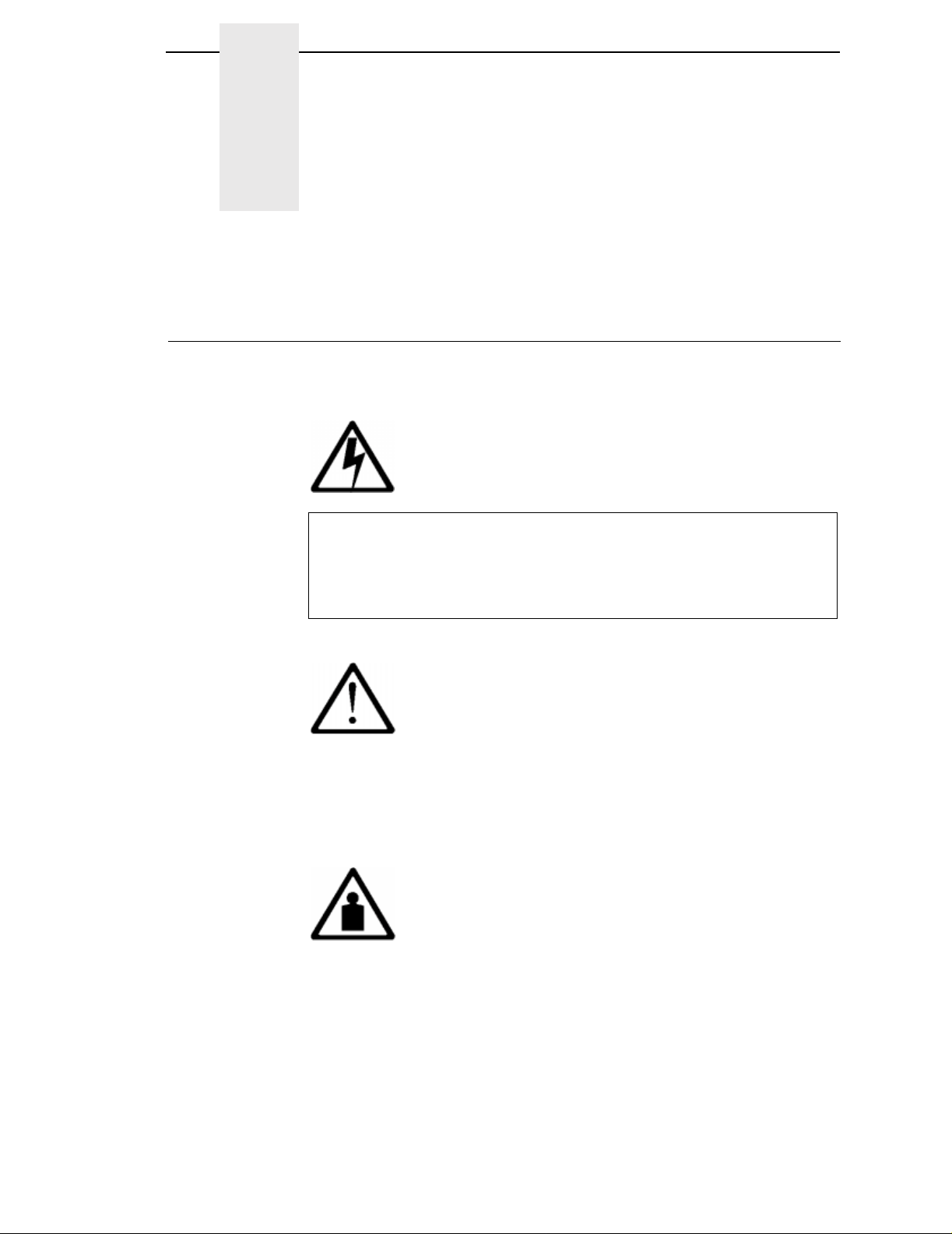
<#> The word Danger next to the lightning slash indicates the
DANGER
presence of a hazard that could cause death or serious
personal injury. Danger and Caution notices are numbered to
help you find the translated versions in the
Notices
booklet.
IBM 4400 Safety
CAUTION
<#> The word Caution next to the exclamation point (!) indicates the
presence of a hazard that could cause moderate or minor
personal injury.
CAUTION
<#> The word Caution next to this symbol indicates a heavy
assembly that requires two or more persons to lift or hold.
13
Page 14
Chapter 1 Notes and Notices
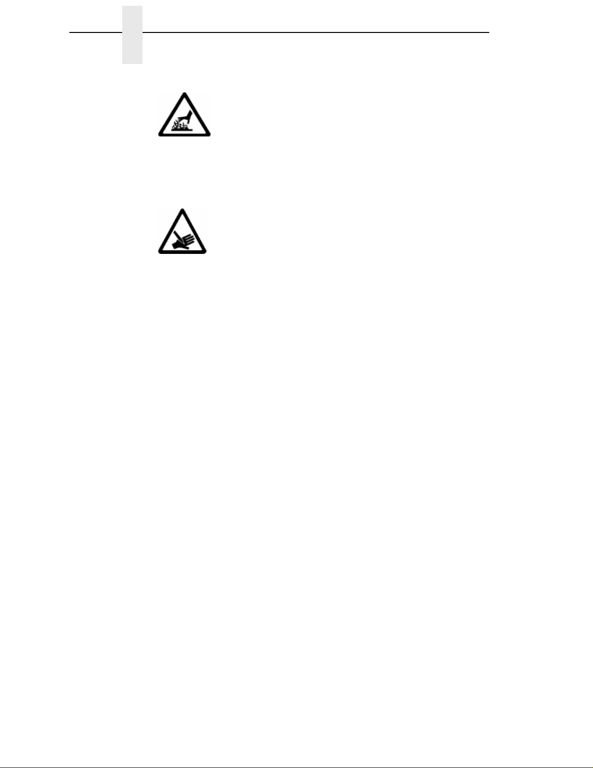
CAUTION
<#> The word Caution next to this symbol indicates a part or
assembly that is hot enough to burn you.
CAUTION
<#> The word Caution next to this symbol indicates a part or
assembly that is sharp enough to cut you.
ATTENTION
The wo rd Attention indica tes the possibility of damage to a program,
device, system, or data.
IMPORTANT
The word Important indicates information vital to proper operation of
the printer.
NOTE:
A note gives you helpful information and tips about printer operation
and maintenance.
14
Page 15

Requesting IBM Service
Requesting IBM Service
Follow the actions in the troubleshooting tables in chapter 5, Diagnostics and
Troubleshooting. Most problems can be easily resolved using these tables. If
you are unable to resolve the problem, you may want to request service from
your IBM service team. To request service on your IBM 4400 Series Thermal
Printer in the U.S. or Canada, call 1-800-358-6661. Service is available from 8
a.m. to 8 p.m. eastern time. To request service in other countries, call your
countryCall Center.
You may call for service free of charge during the printer's warranty period.
You can obtain service after the warranty period has expired if you sign a
service contract agreement with an authorized service provider.
You also can obtain service on a billable-per-call basis after the warranty
period has expired. Please have your service contract information and printer
serial number available when you call. The four digit machine type is 4400.
Please enter this number when prompted.
NOTE: Technical support is also available from the IBM Printing Systems
Division home page at:
http://www.printers.ibm.com
15
Page 16

Chapter 1 Notes and Notices
Printing Conventions in This Manual
Operator panel keys and LCD messages are set off from regular text in this
manual:
• Operator panel keys and indicators are printed boldface.
Example: Press the Cancel key, then press the Pause key.
• Liquid Crystal Display (LCD) messages are printed in capital letters inside
quotationmarks(“”).
Key combinations are denoted by the + (plus) symbol.
Example: Press ↑ + ↓
means
Press the Up↑key and the Down↓key at the same time.
16
Page 17
The 4400 Thermal Label Printer
NOTE: As used in this manual, the terms “4400” and “printer” refer to all
models within the 4400 series.
The printer series consists of a family of high quality, direct thermal and
thermal transfer printers specifically designed for printing labels and tags,
from any MS-DOS
option) based compatible computer.
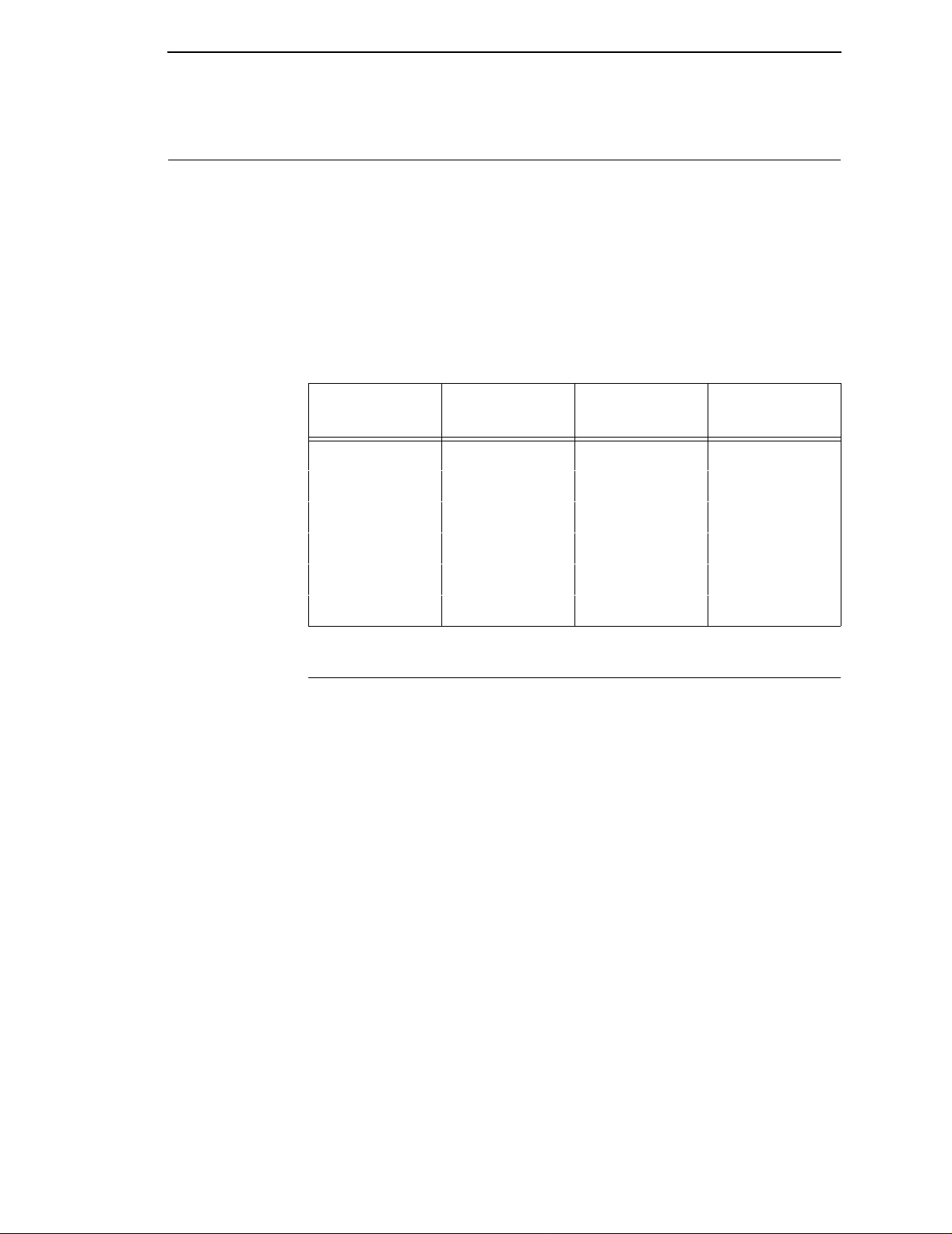
The IBM thermal printer series is comprised of the products detailed in Table
1.
**
, Windows**, ASCII or EBCDIC (with the Coax/Twinax
Table 1. The IBM thermal printer Series
Features
Model
4400-004 10 203 4.1
4400-004 8 300 4.1
4400-006 10 203 6.6
4400-006 8 300 6.6
4400-008 8 203 8.5
4400-008 6 300 8.5
Max Print
Speed (ips)
Printing
Density (dpi)
Max Print
Width (inches)
Features
• Thermal transfer and direct thermal printing.
• Supports over 20 types of bar codes.
• Download forms, fonts and graphics to printer memory.
• High resolution printhead for sharp graphics and text.
• Built-in label rewinder for label Peel-Off operation.
• Label Taken Sensor for detecting removal of labels in Peel-Off or Tear-
Off modes.
• Peel-Off mode for peeling off labels one at a time, before printing the next
label.
• Tear-Off mode for positioning the label at the tear-off position and
detecting its removal before printing the next label.
• Tear-Off Strip mode for printing a specified number of labels and
positioning the last label at the tear-off position.
• 8MB DRAM memory (4MB for the 4400-004).
• 4MB Flash memory.
17
Page 18

Chapter 1 Thermal Printer Technology
Dynamic Print Control provides exceptional print quality. A circuit monitors the
data to be printed and automatically adjusts the energy applied to the thermal
printhead for maximum performance.
The printer can be connected to communicate with the host via RS-232 and
RS-422 serial, Centronics
parallel, and, optionally, coax/twinax host connections or Ethernet
Base-T. The interface cable needed to connect the printer to the host device
is supplied by the user.
Thermal Printer T echnolog y
Quiet and fast, with excellent print quality, the IBM multifunction thermal
printer uses an inline thermal printhead. The operation of a thermal printer is
different from that of a line-matrix or laser printer. The thermal printer uses a
printhead with heating elements and special paper or ribbon.
The Printing Process
The thermal printhead allows two modes of operation:
• Direct Thermal
direct
During
small, rectangular
paper, the dyes and developers in the coating react to the heat and
develop an image. This mode of printing is generally used for short-term
labeling applications.
thermal printing, the thermal printhead selectively heats
thermal
**
-compatible parallel, IEEE**1284 compliant
dots. When these contact the coated thermal
**
10/100
• Thermal Transfer
During thermal
thermal ribbon. The heat reacts with the ribbon and bonds the image to
the paper. This method is used especially for abrasive, long-storage
applications and for specialized applications, such as in extreme
environmental conditions or where tamper-proofing is required.
transfer
printing, the heated thermal dots contact a
18
Page 19

Dynamic Print Control
The thermal printer has a unique feature that provides excellent print quality
by preventing unevenness of print density. Unevenness is usually caused by
the stored heat from previous dots. Print quality largely depends on how the
thermal paper or the thermal ribbon and thermal transfer paper responds to
the heat of the thermal printhead.
During printing, the thermal printhead must reach a set temperature in the
shortest possible time. Then it must cool down to the original temperature in
the shortest possible time after printing. Thus print quality is dependent on the
precise control of the energy supplied to the thermal dots.
The Dynamic Print Control is a method for predicting the quantity of heat
required to print dots based on the results of the previous printing. This
prevents unevenness of print density and results in the printing of narrow-
ladder bar codes or vertical grid lines that are straight from the microscopic
viewpoint.
Thermal Consumables
Dynamic Print Control
Media Selection
Since there are two print modes of operation, there are two kinds of thermal
media:
• Direct thermal media
• Thermal transfer media
Direct thermal media is paper coated with special chemicals that act as an
accelerator, acceptor dye and binder. During direct thermal mode, the heat
from the thermal printhead contacts the paper and causes a chemical reaction
to take place.
There is a wide range of thermal transfer media available, such as film or
synthetic paper substitutes that are excellent in their ability to transfer an
image (print quality) and others in scratch resistance (long storage). Most of
these media options can be die-cut for easy label applications.
NOTE: The term “media” used in this manual refers to all the different kinds
of paper or tag stock that can be used in the printer.
19
Page 20

Chapter 1 Thermal Consumables
Ribbons
IBM offers a wide range of ribbons that have been specifically engineered to
enhance printing capabilities and to prevent premature printhead wear.
Therefore, it is strongly recommended that you use a Genuine IBM Thermal
Ribbon in your printer.
IBM 4400 TTW Thermal T ransf er Ribbon
This ribbon provides superior print quality on coated and uncoated thermal
transfer paper, labels and tags. IBM 4400 TTW ribbons are an excellent
choice for general-purpose applications.
IBM 4400 TTB Thermal T ransf er Ribbon
This ribbon provides excellent high-speed print quality with premium durability
and performance on a wide range of thermal transfer paper and synthetic
labels. IBM 4400 TTB ribbons are formulated to provide excellent print quality
at the highest IBM 4400 print speeds.
IBM 4400 TTR Thermal T ransf er Ribbon
Specifically designed for use with high-end synthetic labels. Provides the
highest heat, chemical, and abrasion resistance where toughness and label
durability are needed.
Ordering Ribbons (U.S. Only)
Ribbons may be purchased from Lexmark Authorized IBM Supplies Dealers
or directly from Lexmark by calling: 1-800-438-2468
Fax orders may be sent to: 1-800-522-3422
Mail orders may be sent to: Lexmark International, Inc., 1221 Alverser Drive,
Midlothian, VA 23113.
Ordering Ribbons (Outside of U.S.)
Order supplies by contacting your local Lexmark International distributor or by
writing to Lexmark International, Inc.
Lexmark International, Inc.
P.O. Box 11427
Lexington, KY, 40575-1427 USA
20
Page 21

Thermal Features
Emulations
The 4400 has the standard IBM ASCII Emulation which provides direct
compatibility with IBM series printers. In addition, the printer has co-resident
IGP and Code V emulations which provide printer system commands for text,
barcodes, graphics, lines, and boxes.
Hard ware Options
Ask your IBM representative about the following options, which can enhance
the versatility of your printer.
• Memory Expansion
16MB DRAM SIMM - Provides additional memory to accommodate
long label formats.
• Coax/Twinax Host Interface
Emulations
Provides connection to an IBM host computer system using a coax or
twinax interface.
• Ethernet** 10/100 BASE T
Allows the user to attach the printer to a LAN (Local Area Network)
rather than attaching it directly to a host system. This Ethernet
Interface server supports 10/100 Base T (UTP) only and is mounted
inside the printer.
21
Page 22

Chapter 1 Setting Up The Printer
:
Setting Up The Printer
CAUTION
<6> The printer weighs between 15.9 kg (35 lb.) and 22.7 kg
(50 lb.). Use two persons to carry the printer. Use
appropriate lifting precautions.
Unpacking The Printer
The printer is shipped in a carton and protective bag. Keep all packing
material in case you need to move or re-ship the printer. Avoid touching the
electrical connectors to prevent electrostatic discharge damage while setting
up the printer.
ATTENTION
ATTENTION
The discharge of electrostatic energy that accumulates on the surface
of the human body or other surfaces can damage or destroy the
printhead or electronic components used in this device.
Damage to the p rinter interface connector may result from placing the
printer on its backside during unpacking or handling.
22
Page 23
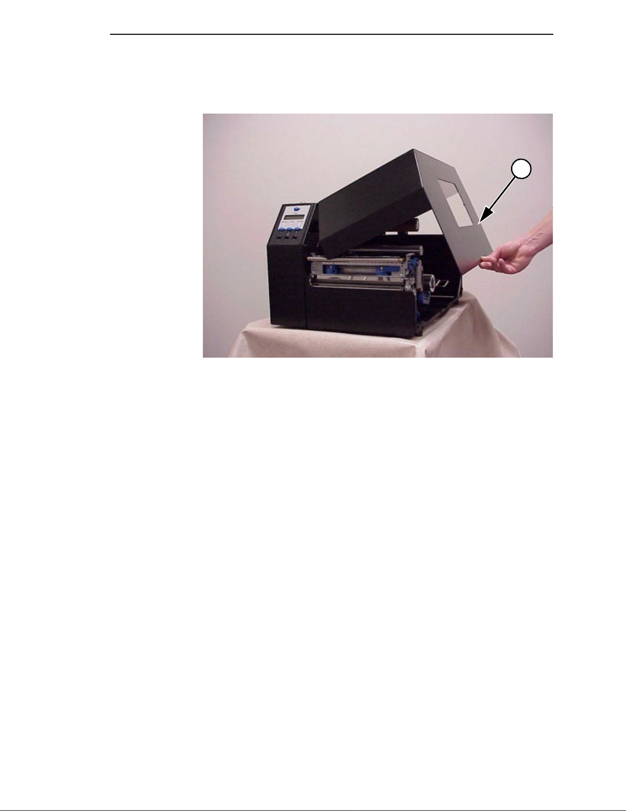
Unpacking The Printer
Open the media cover by lifting it in the center of its bottom right edge.
1
Legend:
1) Media Cover
Remove the tape securing the liner rewinder clamp to the rewinder spindle.
Slide the Media Hanger Guide outward to the end of the Media Hanger. Place
the Guide in the down (horizontal) position and remove the sample roll of
ribbon and media from the media hanger and set them to one side.
23
Page 24
Chapter 1 Setting Up The Printer
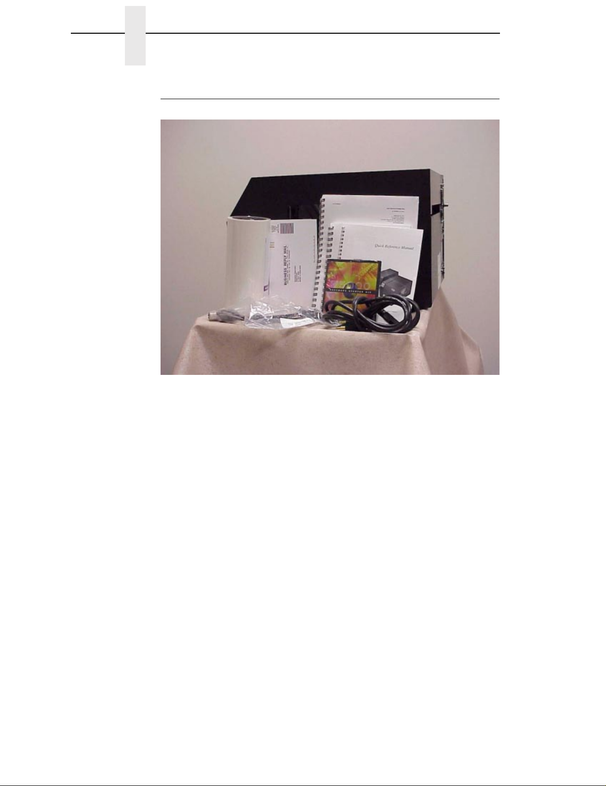
Check List
Your thermal printer kit contains the items listed below.
• The thermal printer.
• AC Powercord
• User’s Manual
• Quick Reference Manual
• Printer Manual CD
• Terminating Resistor Packs
• Ribbon Take-Up Core (mounted in printer)
• Starter Kit Roll Media
• Sample Roll of IBM Thermal Transfer Wax Ribbon (wrapped inside media
roll)
• Printhead Cleaning Pen (wrapped inside media roll)
NOTE: If any items are missing, contact your dealer for replacement parts.
24
Page 25
Installation
Installation
The following sections will guide you through the installation of the printer.
DANGER
<6> The printer should never be operated in a location where
the operator or printer can get wet.
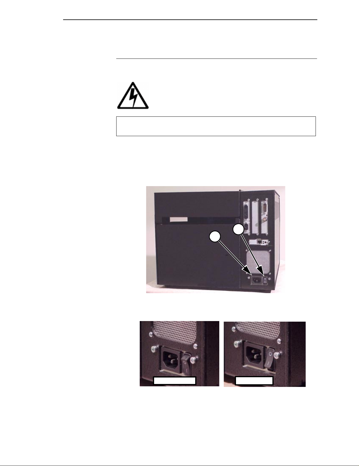
1. Place the printer in a suitable location on a flat level surface that allows
easy access to all sides of the printer. The printer should never be
operated while resting on its side or upside down.
2. Check that the printer power switch is in the OFF (O) position.
Legend:
1) AC Power Receptacle
2) On/Off Power Switch
On Position Off Position
2
1
25
Page 26
Chapter 1 Setting Up The Printer
DANGER
<4>
The following sections will guide you through the installation of the printer.
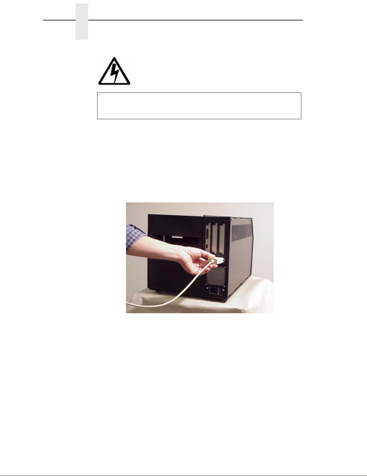
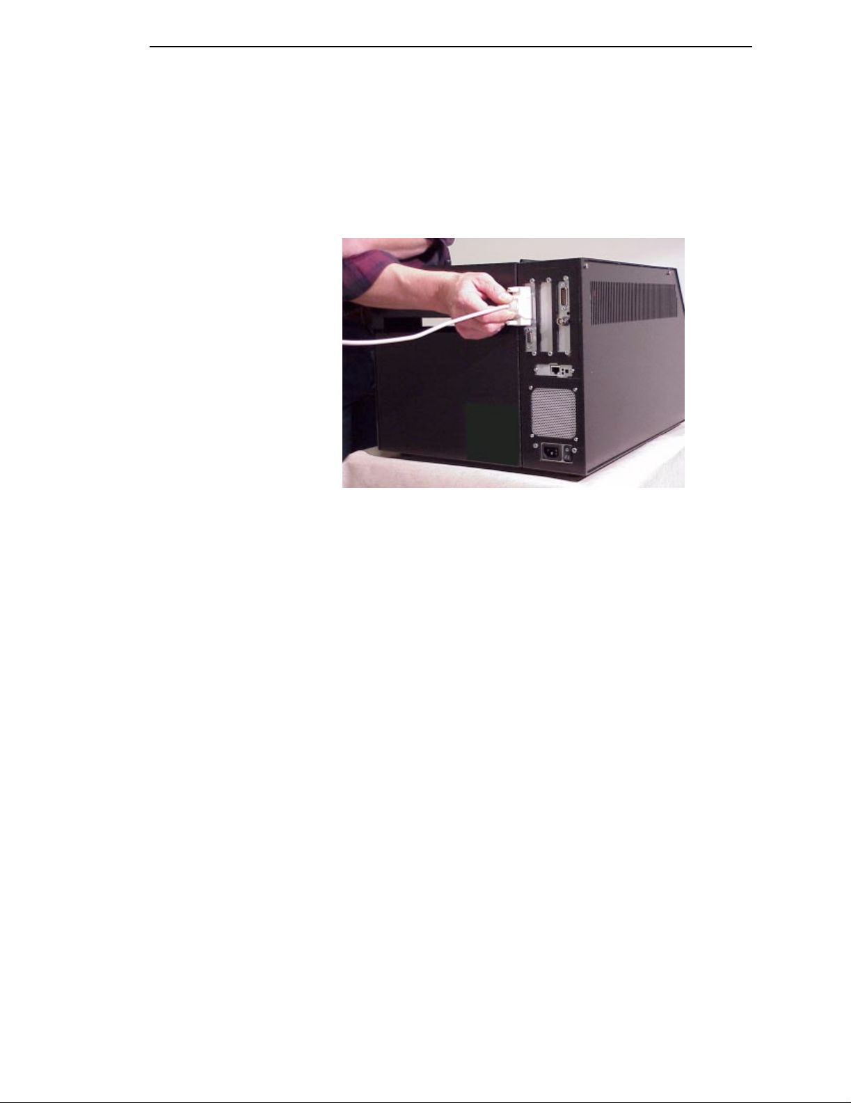
3. Attach Interface
a. Parallel Interface
Do not connect or disconnect any communication port,
teleport, attachment connector, or power cord during an
electrical storm.
Attach a suitable parallel printer cable from the computer to the
Centronics interface connector at the back of the printer. Snap the
bail locks to the Centronics connector to secure the interface cable to
the printer.
26
Page 27
Installation
b. Serial Interface
Attach a suitable serial printer cable from the computer to the DB-25
RS-232 Serial interface connector at the back of the printer. For
additional information on serial cable wiring, refer to “Diagnostics and
Troubleshooting” on page 175.
NOTE: The printer supports simultaneous connection of the Parallel and
Serial interfaces using the Auto Switching feature. See Auto
Switching described on page 165.
27
Page 28
Chapter 1 Setting Up The Printer
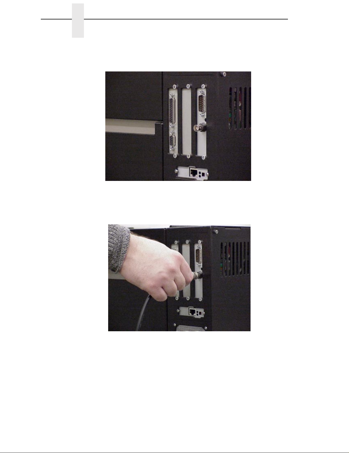
If your printer is equipped with the Coax/Twinax and ethernet interfaces, the
rear I/O panel will look like the picture below.
c. Coax Interface
Attach a suitable coaxial cable from the computer to the coax
connector located in the I/O plate in the back of the printer.
28
Page 29
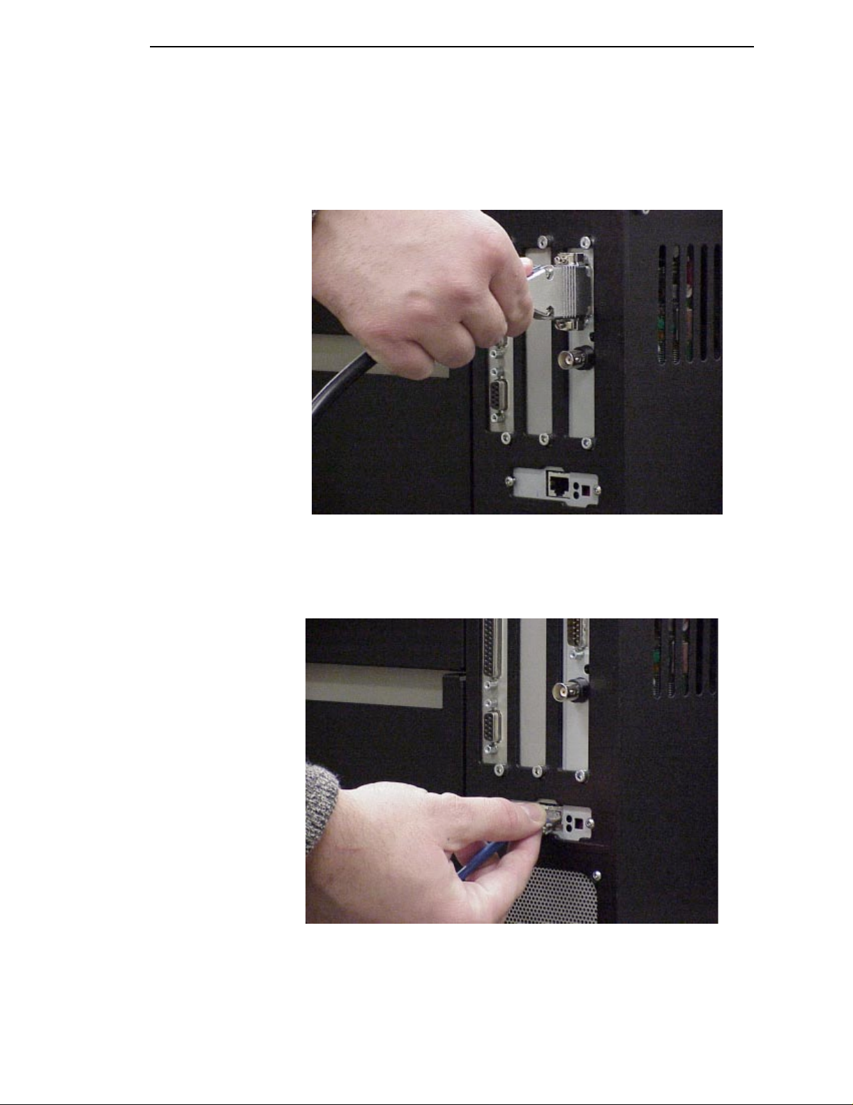
d. Twinax Interface
Attach a suitable twinax cable from the computer to the twinax
connector located in the I/O plate in the back of the printer.
Installation
e. Ethernet Interface
Insert a suitable ethernet cable from your hub or switch to the
ethernet connector located in the I/O panel in the rear of your printer.
29
Page 30
Chapter 1 Setting Up The Printer
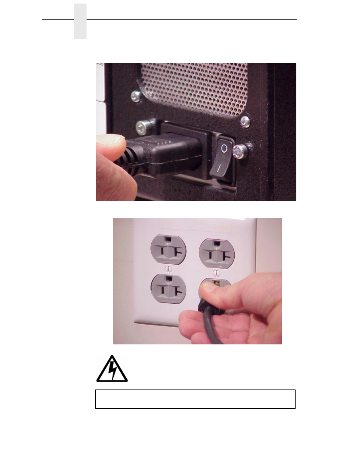
4. Attach the AC power cord to the AC power receptacle in the rear of the
printer.
Attach the AC power cord to a grounded (three prong) electrical outlet of the
proper voltage.
DANGER
30
<1>
Before powering on the printer, ensure that the printer is
plugged into the appropriate power source.
Page 31

2 Operation
Using The Printer
Controls & Indicators
All printer controls and indicators, except for the power switch and ONLINE
status indicator, are located on the front panel of the printer. The power switch
is located in the bottom left hand corner at the rear of the printer. The ONLINE
status indicator is located on top of the printer, directly above the control
panel.
The Control Panel is located at the top left of the printer. The panel has a
back-lighted Liquid-Crystal Display (LCD) with 2 rows of 16-characters each.
The Control Panel also contains the printer control keys. A summary of each
key’s function is provided on the following pages. Detailed descriptions of key
functionality are provided in Chapter 3.
31
Page 32

32
Chapter 2 Using The Printer
Button Description
PAUSE Key
Toggles the printer between
online and offline modes.
JOB SELECT Key None Selects a pre-stored
-
ñ
Decrement Key
FEED Key
Up Key
TEST PRINT Key
Pressing the↵ (Enter) key with
a Diagnostic Test displayed
initiates the test. Pressing the
(Enter) key again terminates the
test.
Function in Online
Mode
Sets printer to Offline
Mode.
Advances the media
one form length.
None Navigates the Test
↵
Function in Offline
Mode
Sets printer to Online
Mode.
printer configuration.
Advances the media
one form length.
Print pattern.
Function in Menu
Mode
Sets printer to Offline
Mode.
Decrements values in
the current menu
selection, or navigates
through selections to
the left.
Navigates the current
menu selection one
level up.
Increments values in
the current menu
selection, or navigates
through selections to
the right.
Control Panel Keys
+
Increment K ey
Page 33

Button Description
Function in Online
Mode
Function in Offline
Mode
Function in Menu
Mode
33
Cancel Key
This key is set to disable from the
factory, except when the Coax/
Twinax option is present. In this
case, the factory default setting is
enable. CANCEL can also be
enabled in the PRINTER
CONTROL menu.
Down Key
Menu Key Sets the printer to
Enter Key
If the↵(Enter) key is locked, the
value will not be selected and an
“ENTER SWITCH LOCKED”
message displays for one second,
followed by a display of the
previously selected value. Pressing
the↓(Down) and↵(Enter) keys
unlocks the↵(Enter) key and
permits value selection. After
unlocking the↵(Enter) key, it is
then used to select the desired
value.
Clears all data in the
printer data buffer
when enabled.
Offline and selects the
Menu mode.
None None Selects the current
Clears all data in the
printer data buffer
when enabled.
Selects the Menu
mode.
Navigates the current
menu selection one
level down.
Navigatesbetween
top level menu
selections.
menu value and
displays an asterisk
(*) next to the value.
Controls & Indicators
Page 34

Chapter 2 Using The Printer
The POWER Switch and Indicator
The printer’s POWER SWITCH is located on the back panel of the printer, in
the bottom left corner. Placing this switch in the ON (|) position applies power
to the printer. Place this switch in the OFF (O) position to remove power when
you have finished using your printer. An illuminated LCD Message Display
indicates the printer power is ON.
Powering On The Printer
When you power on the printer, it executes a self-test. The default power-up
state is online. Once the printer has successfully initialized, the ONLINE
status indicator light illuminates, and the LCD indicates the communication
interface selected and the type of emulation installed.
If there is a fault during the self-test, the ONLINE status indicator flashes, and
a fault message appears on the display. The alarm may also sound, if it is
configured to do so.
34
Page 35

Operating Modes
Operating Modes
Online - In online mode, the printer can receive and print data sent from the
host. Pressing the PAUSE key toggles the printer between the online and
offline mode. The ONLINE status indicator is lit in online mode.
Offline - In offline mode, you may perform operator functions, such as loading
media, or navigating through the printer configuration menu to make changes
or verify option settings. Pressing the PAUSE key toggles the printer from
offline to online mode. The ONLINE status indicator is not illuminated in offline
mode.
Fault - In fault mode, a fault condition exists that must be cleared before
printing can continue. The ONLINE status indicator flashes, the alarm beeps
(if configured to do so) and a descriptive fault message displays.
The current operating mode can be selected through the control panel keys,
or may result from routine operations such as powering on the printer.
35
Page 36

Chapter 2 Loading Media and Ribbon
Loading Media and Ribbon
This section explains how to load roll media, fanfold media, and the ribbon.
The term “media” used in this manual refers to all the different kinds of paper,
label, or tag stock material that can be printed on by the printer.
Your thermal printer can print on continuous paper, adhesive backed labels or
non-adhesive tags packaged in roll or fanfold form.
ATTENTION
IMPORTANT
DO NOT TOUCH the Printhead or the electronic components under the
Printhead Assembly. The discharge of electrostatic energy that
accumulates on the surface of the human body or other surfaces can
damage or destroy the printhead or electronic components used in this
device.
Adhesive backed labels that DO NOT lay flat on the backing liner may
jam the printer. This can cause the label to peel off the liner. The
exposed edges may stick to the label guides and rollers inside the
printer.
If you run out of labels while printing, do not turn the power switch to
the O FF position while reloading labels. Lost data may result. Prior to
printing labels, it is also recommended you enable the Error Recover
sub-menu of the MEDIA CONTROL menu, and save it as the power-on
default. Error Recover forces the printer to automatically reprint a label
that may have been partially printed prior to the PAPER OUT fault
message, after additional labels are properly loaded.
36
Page 37

Loading Roll Media
Loading Roll Media
1. Open the media cover.
2. Slide the media hanger guide outward to the end of the media hanger,
and rotate it downward to a horizontal position.
1
Legend:
1) Media Hanger Guide
2) Media Hanger
2
37
Page 38

Chapter 2 Loading Media and Ribbon
3. Open the pivoting deck by rotating the deck lock lever clockwise to the
end of its travel. The pivoting deck will swing open.
1
Legend:
1) Pivoting Deck
2) Deck Lock Lever
2
38
Page 39

Loading Roll Media
4. Slide the media width guide located on the media damper outward to the
fully extended position.
1
Legend:
1) Media Damper
2) Media Width Guide
2
39
Page 40

Chapter 2 Loading Media and Ribbon
5. Slide a roll of media over the media hanger guide and onto the media
hanger. The media feeds from the top of the roll and towards the front of
the printer.
6. Push the roll to the back of the media hanger, rotate the media hanger
guide to its upright position and slide it inward against the outer edge of
the media roll.
3
Legend:
1) Media Roll
2) Media Hanger
3) Media Hanger Guide
2
1
40
Page 41

Loading Roll Media
7. Thread the media under the media damper and then between the platen
(drive roller) and the printhead. You can also ref er to the arrows on the
printer frame or the Ribbon and Media Loading instruction label inside the
media cover.
1
2
Legend:
1) Printhead Assembly
2) Platen (Drive Roller)
3) Media Damper
3
41
Page 42

Chapter 2 Loading Media and Ribbon
8. Push the media width guide inward until it is flush with the outer edge of
the media.
9. Check the location of the TOF (Top-of-Form)/Paper Out sensor (it is blue
in color and located just behind the platen), and refer to Top-of-Form
Sensor Horizontal Adjustment on page 56.
Legend:
1) Media Width Guide
1
42
Page 43

Loading Roll Media
10. Close the printhead by pressing down on both sides of the front of the
pivoting deck and rotating the deck lock lever counterclockwise against its
stop. This locks the pivoting deck and printhead assembly into the printing
position.
1
ATTENTION
2
Legend:
1) Pivoting Deck
2) Deck Lock Lever
Ensure the pivoting deck is down and locked before attempti ng to print.
Failure to do so will cause a premature failure of the printhead
assembly.
11. For direct thermal operation (no ribbon required) close the media cover
and go to step 12.
For thermal transfer operation (use of ribbon) complete the ribbon loading
procedure (See “Loading Ribbon” on page 48).
Verify that Print Mode in the Printer Configuration Menu is set for the
media type installed (Direct or Transfer). The Print Mode submenu is
located in the MEDIA CONTROL Main Menu. See “Menu Options” on
page 76 for details.
12. Press the FEED key once to verify that the media advances.
13. Press the PAUSE key to place the printer online.
The printer is now ready for printing.
43
Page 44

Chapter 2 Loading Media and Ribbon
Loading Fanfold Media
1. Open the media cover.
2. Slide the media hanger guide outward to the end of the media hanger,
and rotate it downward to a horizontal position.
3. Remove any roll media.
4. Place the fanfold media either behind or beneath the printer, depending
on the desired fanfold supply location. Insert the first few labels through
either the rear or bottom panel opening.
5. Place the media over the media hanger, flush against the back of the
printer.
6. Rotate the media hanger guide to its upright position and slide it inward
against the outer edge of the loaded media.
Legend:
1) Media Hanger Guide
2) Media Hanger
3) Fanfold Media
1
3
2
44
Page 45

Loading Fanfold Media
7. Rotate the fanfold tension arm down by pushing on it through the opening
at the top of the media hanger guide.
8. Open the pivoting deck by rotating the deck lock lever clockwise to the
end of its travel. The pivoting deck will swing upward.
1
2
3
Legend:
1) Fanfold Tension Arm
2) Pivoting Deck
3) Deck Lock Lever
45
Page 46

Chapter 2 Loading Media and Ribbon
9. Slide the media width guide outward to the end of the media damper.
10. Thread the media between the platen (drive roller) and the printhead. You
can also refer to the Ribbon and Media Loading instructions label inside
the media cover. The inner edge of the media should be positioned as far
inward as possible.
11. Slide the media width guide inward against the outer edge of the media.
12. Check the location of the TOF/Paper Out sensor, and refer to “TOF/Paper
Out Sensor Horizontal Adjustment” on page 56. The TOF/Paper Out
sensor is blue in color and located just behind the platen.
.
1
2
Legend:
1) Printhead Assembly
2) Platen
3) Media Width Guide
3
46
Page 47

Loading Fanfold Media
13. Close the printhead by pressing down on both sides of the front of the
pivoting deck and rotating the deck lock lever counterclockwise against its
stop. This locks the pivoting deck and printhead assembly into the printing
position.
Verify that Print Mode in the Printer Configuration Menu is set for the
media type installed (Direct or Transfer). If Thermal Transfer media is
installed, see “Loading Ribbon” on page 48. The Print Mode submenu is
located in the MEDIA CONTROL Main Configuration menu. See “Menu
Options” on page 76 for more information.
1
ATTENTION
2
Legend:
1) Pivoting Deck
2) Deck Lock Lever
Ensure the pivoting deck is down and latched before attempting to print.
Failure to do so may cause a premature failure of the printhead.
14. Press the FEED key once to verify that the labels advance.
15. Close the printer media cover if the thermal transfer operation is not
needed.
16. Press the PAUSE key to place the printer online.
The printer is now ready for printing.
47
Page 48

Chapter 2 Loading Media and Ribbon
Loading Ribbon
Skip this section when using Direct Thermal Printing
1. Slide the appropriate thermal transfer ribbon supply roll onto the ribbon
supply spindle until it is flush against the printer.
2. Open the pivoting deck by rotating the deck lock lever clockwise to the
end of its travel. The pivoting deck will swing upward.
3. Thread the end of the transfer ribbon below the rear ribbon guide and
continue threading between the platen (or media, if loaded) and the
printhead. You can also refer to the arrows on the printer frame or the
Ribbon and Media Loading Instruction label located inside the printer on
the media cover.
6
1
2
3
Legend:
1) Pivoting Deck
2) Platen
3) Deck Lock Lever
4) Rear Ribbon Guide
5) Ribbon Supply Spindle
6) Ribbon Supply Roll
5
4
48
Page 49

Loading Ribbon
4. Wrap the transfer ribbon from the front of the printhead assembly to the
front side of the ribbon take-up spindle. Attach the ribbon to the take-up
core (fiberboard tube) on the ribbon take-up spindle with tape.
When installing a new roll of ribbon, attach the ribbon leader adhesive
strip to the ribbon take-up core. Manually rotate the spindle clockwise to
feed the unusable portion of the ribbon leader around the take-up spindle.
NOTE: Do not attach the ribbon to the ribbon take-up spindle without a core
installed. Proper ribbon tension and ribbon removal is based on use
of fiberboard core.
1
2
Legend:
1) Ribbon Take-up Spindle
2) Ribbon Take-up Core
5. Close the pivoting deck (see page 47).
6. Close the printer media cover if the rewinder is not needed.
7. Verify that Print Mode is set for Transfer in the Print Mode submenu
located in the MEDIA CONTROL Main Configuration menu. See “Menu
Options” on page 76 for more information.
8. The printer is now ready to print.
49
Page 50

Chapter 2 Print Option
Print Option
Label Peel Off
The printer can be set up to automatically peel off labels from the backing
liner and dispense them one at a time while rewinding the liner. This
configuration requires routing the liner through the rollers on the Peel/Tear
assembly properly and use of the printer’s internal rewinder.
1. Open the media cover.
2. Open the front cover.
3. Open the pivoting deck by rotating the deck lock lever clockwise to the
end of its travel. The pivoting deck will swing upward.
4. With the label stock already loaded and exiting from the front of the printer
(see “Loading Roll Media” on page 37), separate the labels from their liner
(about 20 inches worth).
50
Page 51

Label Peel Off
5. Thread the liner over the tear bar behind the top roller and around the
outside of the bottom of the Peel/Tear assembly.
51
Page 52

Chapter 2 Print Option
6. Manually position the leading edge of the first label to just behind the tear
bar of the Peel/Tear assembly.
7. Thread the liner counterclockwise around the rewinder and the rewinder
clamp as shown, and insert the liner end into one of the slots in the
rewinder. Make sure the rewinder clamp is pushed in against the
rewinder.
8. With one hand holding the liner in the slot, use the other hand on the
rewinder clamp and rotate the rewinder counterclockwise until the lever is
taught on the rewinder spindle.
Legend:
1) Rewinder Clamp
2) Rewinder
1
2
52
Page 53

Label Peel Off
9. Verify the leading edge of the first label is still behind the tear bar of the
Peel/Tear assembly.
10. Close the printhead by pressing down on both sides of the front of the
pivotingdeck and rotatingthe decklock counterclockwiseagainst its stop.
This locks the pivoting deck and printhead assembly into the printing
position.
11. Close the front door. The door must be closed for the Label Sensor to first
sense the label and then its removal.
1
2
3
Legend:
1) PIvoting Deck
2) Label Only
3) Deck Lock Lever
12. For automatic label peel-off mode, set Media Handling to Peel-Off under
the MEDIA CONTROL Main menu. See Chapter 3 for more information
on configuring the printer.
13. Close the media cover.
53
Page 54

Chapter 2 Printing Adjustments
Printing Adjustments
Printhead Pressure Adjustment
1
Legend:
1) Printhead Pressure Adjustment Dial
Adjustment of the printhead pressure is sometimes required to obtain
optimum printing results with variations in media thickness and width. The
printhead pressure adjustment dial is shown above.
In general, the printhead pressure should be adjusted to the minimum value
which produces the desired print quality. Following this procedure will help to
minimize printhead wear. The numbers on the Printhead Pressure Adjustment
Lever are relative only and do not indicate a specific printhead pressure.
54
Page 55

Printhead Pressure Block Adjustments
Printhead Pressure Block Adjustments
6
1
Legend:
1) Left Pressure Block
2) Left Pressure Block Handle
3) Pressure Block Adjustment Scale
4) Right Pressure Block
5) Right Pressure Block Pointer
6) Lead Screw Knob
The Printhead Pressure Pad Adjustments are used to obtain best printing
results under a variety of media and ribbon conditions.
Under normal printing conditions, the optimum position of the left pressure
block when its handle detent is positioned in the notch in the pivoting deck. If
media/ribbon widths of less than one-third the printer’s maximum printing
width are used, it may be necessary to move the left pressure block further
left by using the handle and overriding the detent. The left pressure block can
only be moved manually using its handle.
The proper setting for the pressure blocks is when they are evenly spaced
across the width of the media. The proper setting for the right pressure block
is with the right pressure block pointer positioned on the right edge of the
media in use. The right pressure block is adjusted by turning the Lead Screw
Knob located in the right side of the pivoting deck.
To check the correctness of the pressure block positions, print the grey test
pattern (see the DIAGNOSTICS/Printer Tests menu item). The pressure
blocks should then be positioned to obtain a uniform printing density across
the media. In most cases, only the right pressure block will need adjustment.
2
3 4
5
55
Page 56

Chapter 2 Printing Adjustments
Label V ariations and the TOF/Paper Out Sensor
Your printer is equipped with a sensor that is used to detect the TOF (Top-ofForm) position as well as a paper out condition. Depending on the type of
media used, the sensor will either “see through” the label liner, index hole or
notch in the media (
on the media with reflective label backing (
the correct option must be selected under the Gap Sense item in the MEDIA
CONTROL Main Menu. When Transmissive is selected, the TOF position is
based on the trailing edge of the gap, notch, or hole. When Reflective is
selected, the TOF position is based on the leading edge of the black stripe.
A third option, None, is also available under the Gap Sense item in the MEDIA
CONTROL menu. The None option must be selected when continuous media
with no gap, notch hole, or black stripe is installed. The TOF will be based on
the Label Length value set under the Media Control menu or by the Forms
Length command sent via host computer software.
NOTE: When Gap Sense = None, Calibrate should still be performed to
automatically establish the optimum Paperout Threshold value.
Transmissive
sensing) or detect a black horizontal stripe
Reflective
sensing). In either case,
TOF/Paper Out Sensor Horizontal Adjustment
In order to accurately detect the gap, hole, notch or narrow width black stripe,
the Top-of-Form sensor can be moved along the width of the media from the
inner media edge to within .65 inches from the maximum media width or the
right side. The position of the sensor is changed by using the handle at the
back of the sensor to slide the sensor to the desired position. The actual
location of the sensor is indicated by the notch located in the center in the
sensor visible when the pivoting deck is in the open position.
In the Transmissive Mode, the sensor should be located directly under the
inter-label gap, hole or notch, while in the Reflective mode it should be
positioned as close as possible in the middle of the width of the label black
stripe. For media with no gap and no black stripe, the sensor should be set
under the media to detect a paperout condition.
When using the TOF/Paper Out sensor, it is the responsibility of the user to
adhere to the media specifications described in Appendix A of this manual
and to ensure that the Label Length value set in the MEDIA CONTROL Main
Menu (or Label Length value sent via software command) matches the
physical length of the label or tag stock installed in the printer. In addition, the
operator should perform the TOF sensor Calibrate procedure described below
whenever a different type of media sensing will be required (Transmissive or
Reflective), when installing never-before-tried media, or when the printer is
experiencing loss of TOF position. Loss of Top-of-Form is usually followed by
a fault message on the LCD, such as “GAP NOT DETECTED See Manual” or
“PAPER OUT Load Paper.”
56
Page 57

Calibrating the TOF/Paper Out Sensor
Calibrating the TOF/Paper Out Sensor
Due to manufacturing differences in media, the TOF (Top-of-Form)/Paper Out
sensor may have difficulty distinguishing the difference between the label and
the liner (gap) or the label and the black stripe or a paperout condition. When
this occurs, the printer will display an error message on the LCD such as
“GAP NOT DETECTED See Manual” or “PAPER OUT Load Paper.” The
printer’s sensitivity for detecting the TOF position or paper out condition of the
media installed can be optimized by using the Calibrate feature of the printer.
TOF/Paper Out sensor sensitivity can be improved by changing the values of
Paper Calibrate/Gap Threshold and/or Paper Out Threshold. These values
can be changed manually within the MEDIA CONTROL menu, or can be
determined by the printer automatically by performing the Calibrate
procedure.
Any changes to sensor parameters which occur as a result of the Calibrate
procedure, regardless if performed automatically or manually, take effect
immediately within the current configuration menu, but are not automatically
saved. If the Calibrate is performed again the new values will overwrite the
previous values for the current menu.
The new values can be saved into non-volatile memory (menus 1-8 only) by
using the Save Configuration procedure. If the current menu in use is the
Factory menu, the values will take effect but will not be saved into memory
and will be lost when the printer is powered off.
When Paper Calibrate has completed successfully, the Sensed Distance
selection in the MEDIA CONTROL menu will display a distance in inches
based on the media type in use:
• transmissive media = the label length plus one gap length
• reflective media = the distance from the leading edge of one black
stripe to the leading edge of the next black stripe.
The Sensed Distance value can not be changed manually and is updated only
as a result of the Paper Calibrate procedure. The factory default value of
Sensed Distance is 0.00 inches.
If Calibrate fails to determine the proper values and ends with a fault message
displayed (GAP NOT DETECTED or LOAD PAPER), you can either try it
again or manually change the Gap Threshold and/or Paper Out Threshold
values under the Media Control/Paper Calibrate menu.
Once the correct values are determined and the Label Length setting in the
MEDIA CONTROL menu is equal to or slightly less than the physical label
length, press the FEED key to advance media and determine if it consistently
stops at the correct TOF position each time.
57
Page 58

Chapter 2 Printing Adjustments
Calibrate Procedure
Calibrate is enabled via the front panel by using the Menu Key and navigating
through the MEDIA CONTROL menu or by using the Test Print Key.
The Test Print Key requires the fewest key strokes to begin the Calibrate, but
the user must still navigate through the MEDIA CONTROL menu to view the
results regarding value changes to the Gap Threshold, Paper Out Threshold,
and Sensed Distance.
NOTE: Verify that the media installed in the printer matches the M EDIA
CONTROL menu Gap Sense option (Transmissive, Reflective, or
None).
Verify that the Top-of-Form sensor is horizontally positioned to permit
sensing of the notch, gap, or black stripe. (See “TOF/Paper Out
Sensor Horizontal Adjustment” on page 56.)
Running Calibrate via the MEDIA CONTROL Menu
1. Press and release the PAUSE key to place the printer Offline.
2. Press and release the↓and↵keys simultaneously to unlock the printer
menu. “ENTER SWITCH UNLOCKED” appears on the LCD.
.
3. Press the key until “MEDIA CONTROL” appears on the LCD.
4. Press the↓key until “Paper Calibrate/Run Calibrate” appears.
5. Press the↵key. The media will advance approximately 11 inches.
.
.
The procedure is completed successfully if no fault is displayed and the
Sensed Distance value is correct (See “Sensed Distance” on page 98).
Sensed Distance value will be updated only when Gap Sense =
Transmissive or Reflective. When Gap Sense = None, only Paper Out
Threshold will be updated.
If a fault message such as “GAP NOT DETECTED See Manual” or
“PAPER OUT Load Paper” appears while performing the Paper Calibrate
procedure, press the PAUSE key and perform the Calibrate procedure
again.
6. Press the PAUSE key until “OFFLINE” appears on the LCD.
7. Press the FEED key. The media should advance one forms length.
NOTE: If Clip Page = Enable (factory default) in the MEDIA CONTROL
menu, the printer will stop at the first TOF (Top Of Form) position of
the transmissive gap, notch, or hole, or reflective black strip that it
detects. This is regardless of the Label Length value selected under
the MEDIA CONTROL menu.
If Clip Page = Disable in the MEDIA CONTROL menu and the Label
Length value is longer than the physical label length of the media in
use, the printer will continue to advance media to achieve that Label
Length value and then stop at the next TOF position.
8. Press the PAUSE key to place the printer Online.
58
Page 59

Calibrate Procedure
NOTE: The amount of media advancement is also based on which Media
Handling selection is enabled under the MEDIA CONTROL Main
menu. ‘Tear-Off’ and ‘Tear-Off Strip’ will advance the media until the
Top-of-Form of the next label is positioned over the Tear bar. When
‘Continuous’ Media Handling is selected the media will advance only
until the Top-of-Form of the next label is positioned under the
printhead.
Running Calibrate Via The T est Print Key
1. Press and release the PAUSE key to place the printer Offline.
2. Press the Test Print Key until Printer Test/Calibrate appears on the LCD.
3. Press the
The procedure is completed successfully if no fault is displayed and the
Sensed Distance value is correct (See “Sensed Distance” on page 98).
Sensed Distance value will be updated only when Gap Sense =
Transmissive or Reflection. When Gap Sense = None, only Paper Out
Threshold will be updated.
4. Press the PAUSE key until “OFFLINE” appears on the LCD.
5. Press the FEED key. The media should advance one forms length.
NOTE: If Clip Page = Enable (factory default) in the MEDIA CONTROL
6. Press the PAUSE key to place the printer Online.
↵ key. The media will advance approximately 11 inches.
menu, the printer will stop at the first TOF (Top Of Form) position of
the transmissive gap, notch, or hole, or reflective black strip that it
detects. This is regardless of the Label Length value selected under
the MEDIA CONTROL menu.
If Clip Page = Disable in the MEDIA CONTROL menu and the Label
Length value is longer than the physical label length of the media in
use, the printer will continue to advance media to achieve that Label
Length value and then stop at the next TOF position.
The amount of media advancement is also based on which Media
Handling selection is enabled under the MEDIA CONTROL Main
menu. ‘Tear-Off’ and ‘Tear-Off Strip’ will advance the media until the
Top-of-Form of the next label is positioned over the Tear bar. When
‘Continuous’ Media Handling is selected the media will advance only
until the Top-of-Form of the next label is positioned under the
printhead.
59
Page 60

Chapter 2 Cleaning
Cleaning
Depending on the media used, the printer may accumulate residues (media
dust, adhesives, etc.) as a by-product of the normal printing process. To
maintain top printing quality, these residues should be removed by a periodic
cleaning of the printer.
General
Periodic cleaning should be performed on all rollers, guides, and assemblies.
Low pressure air can be used to remove dust in the printer. Isopropyl alcohol
and a cotton swab should be used to clean any areas where media dust,
adhesives, etc. have accumulated. This general cleaning will insure that all
parts are free of residue which may degrade print quality.
The media path and printhead should be cleaned each time a new roll of
media is installed in the printer.
Printhead
As you use your printer, the printhead may become dirty resulting in poor print
quality. You should clean the printhead when replacing the ribbon or installing
new media.Clean the printhead with the printhead Cleaning Pen supplied with
the printer. The printhead heating elements (light brown area) is most
important. Keeping your printhead clean will help to maintain its life.
60
Page 61

Printhead
1. Rotate the deck lock clockwise to open the pivoting deck and remove any
media and ribbon (if loaded) to gain access to the printhead assembly
heating element area.
1
2
Legend:
1) Pivot Deck
2) Deck Lock Lever
2. Gently rub the felt tip of the Cleaning Pen or a cotton swab with Isopropyl
alcohol across the printhead heating elements (light brown area).
Allow the printheadto dry for one minute before reloading the labels.
61
Page 62

Chapter 2 Cleaning
62
Page 63

3 Configuring the Printer
Overview
The configuration process is done using the printer configuration keys on the
control panel and includes the following:
• Configuring the printer for different host interface options
• Customizing label formats
• Checking printer status
• Running various maintenance tests
NOTE: Control codes sent by the host system will override the control panel
Menu Navigation
settings.
This section explains how to use the control panel to change individual
settings and save them as a customized configuration. For details on the
control panel keys and how they work, see “Controls & Indicators” on page
31.
Pressing↓and↵ together unlocks or locks the printer menu (offline mode
only) and permits value selection. This is the default key combination for
locking/unlocking the printer. You can change the key combination. See “Set
Lock Key” on page 101.
63
Page 64

Chapter 3 Menu Navigation
Setting Printer Configuration Parameters
Configuration parameters are set from the control panel or are retrieved from
the printer’s memory. The parameters define how the printer will respond to
command and interface signals from the host computer.
The configuration menu structure consists of top-level menus and various
parameter selections under each top-level menu.
NOTE: Many of the selectable configurations refer to printer options or
features that may or may not be present in your printer. Selecting an
option or feature that is not present will result in no action being
performed by the printer, or an ‘OPTION NOT INSTALLED’ message
displayed.
Moving Within the Configuration Menu
Movement within the configuration menus is controlled by using the
appropriate navigation keys. Figure 1 shows how to move through the menu
system. See “Controls & Indicators” on page 31, for more details on the
function of the operator panel keys.) This example configures the printer for
Direct Thermal operation.
Figure 2 is a configuration printout of a typical printer. This printout illustrates
some of the possible parameter selections which can be made from either the
printer configuration menu or a host computer.
Figure 3 shows the top level overview of the menu structure. A brief
description of the function of each top-level menu selection is given below
each top-level menu selection.
Figure 4 shows a more detailed view of the top level of the menu system. Not
all possible top-level menu selections are available simultaneously since their
presence depends on the installed options as well as specific selections made
in other areas of the menu system.
Use these basic guidelines to move throughout all the configuration menus.
You can select different options and save them as the power on default;
however, they can only be saved to configurations menus 1-8, as the factory
configuration menu can not be altered or saved over.
When the printer is online, the first line of the LCD indicates ONLINE and the
second line lists the active interface port and type of emulation.
To configure the printer, it must be offline. If the ONLINE indicator is lit, press
and release the PAUSE key to place the printer offline. When the printer is
offline, OFFLINE appears on the top line of the LCD. Pressing the key
causes the printer to enter the printer configuration menu system and
CONFIG. CONTROL appears on the next line. When in the printer
configuration menu system the LED indicator is illuminated.
.
.
.
64
Page 65

Selecting a Menu Option
Step Press LCD Notes
1. OFFLINE
2.
3. OFFLINE
4. OFFLINE
5.
6.
7.
Figure 1. Moving within the Configuration Menu
↓& ↵
.
.
.
.
.
.
↓ UNTIL
+or –
↵
ENTER SWITCH
UNLOCKED
CONFIG. CONTROL
MEDIA CONTROL
Print Mode
Transfer*
Print Mode
Direct
Print Mode
Direct*
Allows you to make
configuration changes.
Enables the printer
configuration menu.
Selects the MEDIA
CONTROL top level
menu.
Cycle through the
choices.
Selects the Direct transfer
mode.
Selecting a Menu Option
By default, the↵key is “locked” when the printer is turned on. The purpose of
this is to prevent accidental changes to the configuration menu. If you press
the↵key when the key is locked, the message ENTER SWITCH LOCKED is
displayed on the LCD for one second, and the value will not be selected.
To unlock the↵key, press the↓and↵keys simultaneously.
This toggles the enter lock function.
IMPORTANT
If this function is performed while the↵key is locked, the message
ENTER SWITCH UNLOCKED will be displayed for one second, and the
ENTER key will be unlocked.
If this function is performed while the↵key is unlocked, the message
ENTER SWITCH LOCKED will be displayed for one second, and the
key will be locked.
When the ↵ key is pressed (with the ↵ key unlocked), the value displayed is
entered and the configuration is changed immediately.
This c hange takes effect for all subsequent data and operations for the
printer as soon as ENTER Key is pressed and the asterisk (*) is
displayed. The configuration change(s), stay in effect only while the
printer is powered on. When the power is turned off, all current
configuration w ill be lost unless changes made to it are saved via the
CONFIG. CONTROL menu.
↵
65
Page 66

Chapter 3 Menu Navigation
To save configuration information permanently or to select it as the power-up
default, see “Saving a Configuration” on page 68.
Changing Printer Settings
Changing printer settings, such as print speed or emulation, is referred to as
configuration. Configure the printer through the control panel.
1. Make sure the printer is offline. If the ONLINE indicator is lit, press the
PAUSE key to enter the offline mode. The following message will display:
OFFLINE
.
2. Press key until the following message displays.
.
.
OFFLINE
MEDIA CONTROL
3. Press↑ or↓to cycle through these options:
• Print Intensity
• Print Speed
• Slew Speed
• Print Mode
• Ribbon Select
• Media Handling
• Paper Feed Shift
• Gap Sense
• Label Length
• Label Width
• Ver Image Shift
• Hor Image Shift
• Orientation
• Ribbon Width
• Paper Calibrate (Run)
• Paper Calibrate (Gap Threshold)
• Paper Calibrate (Paper Out Threshold)
• Sensed Distance
• Auto Map Select
• Auto Label Width
• Num Auto Labels
• Tear Strip Time
• Clip Page
• Error Recover
• Display Ribbon
• Ribbon Low
• Units
66
Page 67

Changing Pr inter Settings
4. When the menu item displays, press the + or - key and hold to scroll
through the possible selections.
5. Press the↵key to select a value. An asterisk (*) displays next to the
selected value.
.
.
6. If there are more values you want to change, use the
keys to access the value and the↵key to select it. At any time, you may
press the key to return to the top level menu.
7. At any time, you may press the PAUSE key twice to exit the configuration
menu and place the printer online. Once you have finished selecting all
your options, save your configuration.
.
.
.
.
,↑, ↓, +,
and
−
IMPORTANT
If you do not save your configuration, all your new values will be lost
when you turn off the printer.
67
Page 68

Chapter 3 Configuration Options
Configuration Options
Saving a Configuration
You can save up to eight different configurations to meet eight unique print job
requirements. For example:
Factory: Factory Default (This cannot be altered.)
Config. 1: Selects IEEE 1284 Parallel Interface
Selects Label Width of 4 inches
Selects Label Length of 24 inches
Selects Hor Image Shift of 0.20 inches, etc.
Config. 2: Selects Centronics Parallel Interface
Selects Label Width of 2.2 inches
Selects Page Label Length of 25.0 mm
Selects Ver Image Shift of 0.10 inches, etc.
The configurations are saved and stored in non-volatile memory for later use.
These configurations, including the factory default configuration, will not be
erased from memory when the printer power is turned off.
If you do not save your configuration (to the non-volatile memory) before you
turn off the printer, any changes made to that current configuration will be lost.
NOTE: If the Protect Configs. option is enabled, the new configuration will not
be saved unless the existing configuration has been deleted.
Follow these steps to save a new configuration:
1. Make sure that the printer is offline. If the ONLINE indicator is lit, press
the PAUSE key to take the printer offline. Press the key until the
followingmessage displays:
OFFLINE
CONFIG. CONTROL
2. Press the↓key until the following message displays:
Save Config.
1*
.
.
.
68
3. Press the
factory default configuration is not listed.
4. When the desired number displays, press ↵ to select it. The following
message displays briefly:
Saving
Configuration
- or + key to cycle through the options (1-8). Note that the
Page 69

Modifying a Saved Configuration
When processing is completed, the display shows:
Save Config.
X*
NOTE: If the configuration number has been previously saved and the
Protect Configs. option is enabled under CONFIG CONTROL, the
followingerror message displays:
CONFIG. EXISTS
Delete First
If the above occurs, see “Modifying a Saved Configuration” on page
69, step 4.
It is recommended that you print your configuration and store it in a safe place
for future reference. Refer to “Printing a Configuration” on page 71.
Modifying a Saved Configuration
You can change a saved configuration by rewriting over it. For example, you
can modify Config. 1, shown below. Suppose you want to keep all the settings
but you want to select the parallel Centronics interface instead of the IEEE
1284 interface.
Config. 1: Selects IEEE 1284 Parallel Interface
Selects Label Width of 4 inches
Selects Label Length of 24 inches
Selects Hor Image Shift of 0.20 inches, etc.
1. Load the configuration to be changed (for example, Config. 1).
a. Make sure that the printer is offline. If the ONLINE indicator is lit,
press the PAUSE key to take the printer offline. Press the key
until the following message displays.
OFFLINE
CONFIG. CONTROL
b. Press the↓key until the following message displays.
Load Config.
Factory
.
.
.
c. Press the
d. When the desired number displays, press the ↵ key to select it. The
following message is displayed while loading.
Loading Saved
Configuration
+ or - key to cycle through the options: Factory 1-8.
69
Page 70

Chapter 3 Configuration Options
Then, the following message displays when it is loaded:
Load Config.
X*
2. Move through the menu and change all the desired values. (In this
example, under Parallel Port, you would change the value from IEEE
1284 to Centronics.)
3. Press the↵key to save each new value. An asterisk (*) displays.
4. Before saving the modified configuration, you must delete the original
configuration if the Protect Configs. option is enabled.
a. Press the↑or↓key until the following message displays:
Delete Config.
1*
b. Press the
desired number displays, press the ↵key to select it. The following
message is displayed.
Deleting
Configuration
Then, the following displays when it is deleted:
Delete Config.
X*
5. Save the new configuration as described in the “Saving a Configuration”
on page 68. Make sure you select the same number (e.g., Config. 1)
when saving the modified configuration. The new configuration writes
over the existing one.
6. Print a copy of this newest configuration and store it in a safe place. Refer
to the “Printing a Configuration” on page 71.
+ or - key to cycle through t he options (1-8). When the
70
Page 71

Printing a Configuration
Printing a Configuration
It is recommended that you print and store your configurations for future
reference. The printout provides a list of the parameters that were set when
you configured the printer. A sample configuration printout is shown in Figure
2.
To print a configuration:
1. Make sure the printer is offline. If the ONLINE indicator is lit, press the
PAUSE key to take the printer offline. Press the key until the
followingmessage displays.
OFFLINE
CONFIG. CONTROL
2. Press the ↓key until the following message displays:
Print Config.
Current*
3. Press the
Current*
Factory
Power-Up
All
1-8 customized configurations
4. When the desired option displays, press the ↵key. The printer prints the
specified configuration. Refer to Figure 2, for a sample configuration
printout.
NOTE: If the configuration you want to print has not been saved, the
+ or - key to cycle through the following printout options.
following message will display momentarily:
.
.
.
CONFIG. DOES NOT
EXIST/Save First
This message indicates that no configuration menu has been saved
under the configuration value you have selected and therefore cannot
be printed. You must either select another configuration to print or
load and then save a configuration to that configuration value first.
71
Page 72

Chapter 3 Configuration Options
72
Figure 2. Sa m ple Configuration Printout (sheet 1 of 3)
Page 73

Printing a Configuration
Figure 2. Sample Configuration Printout (sheet 2 of 3)
73
Page 74

Chapter 3 Configuration Options
74
Figure 2. Sample Configuration Printout (sheet 3 of 3)
Page 75

Menu Overview
Printing a Configuration
PRINTER
CONTROL
(page 76)
Used to select the desired
emulations and various
printer operating
parameters.
CONFIG.
CONTROL
(page 76)
Used to name, store, and
retrieve up to eight different
printer configurations.
SELECTED
EMULATIONS
(page 77-page 80)
Emulations selected from
the PRINTER CONTROL
menu appear here. There
are typically multiple
emulations relating to
graphics languages,
particular printers and
optional host interface
protocols.
MEDIA
CONTROL
(page 76)
Used to control various
parameters related to print
quality, media, and ribbon.
DIAGNOSTICS
(page 80)
Used to select various
printer tests, monitor and
record printer performance.
PARALLEL
PORT
(page 80)
Used to select various
parallel port related
parameters.
.
Press to select the next top level menu.
.
.
Press ↓ or ↑ to move within each top level menu.
Notes:
1. Shaded boxes denotes the top-level menu location where the selected ite ms appear. Only the selected items
will appear in the top-level menu.
2. Page numbers in top-level menu selections refer to the location of detailed menu item information.
SERIAL
PORT
(page 80)
Used to select various
serial port related
parameters.
OPTIONAL
PORT(S)
(page 80-page 81)
Used to select optional host
interfaces.
Figure 3. Configuration Top-Level Menu Overview
75
Page 76

Chapter 3 Menu Options
Menu Options
CONFIG.
CONTROL
Load Config. (page 92)
Save Config. (page 100)
Print Config. (page 98)
Delete Config. (page 89)
Power-Up Config. (page 98)
Protect Configs. (page 99)
Name Config 1-8 (page 94)
Reset Cfg Names (page 99)
PRINTER
CONTROL
ASCII Emulation (page 92)
CTHI Emulation (1) (page 88)
Active IGP Emul (page 82)
Power Saver Time (page 98)
Display Language (page 89)
Alarm (page 83)
Power-up State (page 98)
Ptr Setup SFCC (page 99)
Overwrite Files (page 97)
View File List (page 102)
Optomize&Reboot (page 95)
Print File List (page 98)
Cancel Key (page 87)
Compatibility (page 87)
Advanced User (page 83)
Auto Locking (page 83)
Set Lock Key (page 101)
Ptr Setup Parse (page 99)
Glob Mem Adjust (page 90)
Max Cache Memory (page 93)
Max Cached Char (page 93)
Standard Chars. (page 102)
Bold Chars. (page 87)
Extra Bold Char. (page 89)
MEDIA
CONTROL
Print Intensity (page 98)
Print Speed (page 99)
Slew Speed (page 101)
Print Mode (page 99)
Ribbon Select (page 100)
Media Handling (page 94)
Paper Feed Shift (page 97)
Gap Sense (page 90)
Label Length (page 91)
Label Width (page 92)
Ver Image Shift (page 102)
Hor Image Shift (page 90)
Orientation (page 95)
Ribbon Width (page 100)
Paper Calibrate (page 97)
Paper Calibrate (Gap Thresh)(page 90)
Paper Calibrate (Pap Out Th) (page 97)
Sensed Distance (page 101)
Auto Map Select (page 84)
Auto Label Width (page 83)
Num Auto Labels (page 94)
Tear-Strip Time (page 102)
Clip Page (page 87)
Error Recover (page 89)
Display Ribbon (page 89)
Ribbon Low (page 100)
Units (page 102)
.
Press to select the next top level menu.
.
.
Press ↓ or ↑ to move within each top level menu.
Press + or - to cycle through each possible menu item value.
1. Appears only if the CTHI emulation is installed.
NOTE: Bold selections are available only when the Advanced User
selection (under PRINTER CONTROL) is enabled.
76
Figure 4. Menu Options
Page 77

Printing a Configuration
COAX
(1)(2)(3)
SETUP
Primary Sets (page 136)
Translation Tbl (page 145)
PA1 (page 134)
PA2 (page 134)
Buffer Reprint (page 111)
Buffer Print (page 111)
Coax Type (page 118)
Active Char Set (page 108)
Secondary Sets (page 140)
Prt Partial Line (page 139)
Early Print Cmpl (page 121)
Alt. Set 80-9F (page 108)
Intervention Req (page 130)
CR at MPP+1 (page 119)
NL at MPP+1 (page 133)
Position Aft FF (page 135)
Last Char = FF (page 131)
Null Suppression (page 133)
FF Validity (page 124)
Auto Skip At End (page 109)
FF After Job (page 123)
CR, EM, & NL (page 119)
Host Override (page 128)
Format Control (page 125)
Cancel IGP/DCU (page 112)
Lead-in Chars (page 131)
Change Case (page 112)
Set Text Orientn (page 142)
Max. Print Width (page 132)
TWINAX
(1)(2)(3)
SETUP
Primary Sets (page 137)
Translation Tbl (5) (page 146)
Buffer Print (page 111)
Twinax Type (page 146)
Active Char Set (page 108)
Secondary Sets (page 141)
Prt Partial Line (page 139)
5225 World Trade (page 107)
Cancel IGP/DCU (page 112)
Lead-in Chars (page 131)
Alt. Set 80-9F (page 108)
Graphic Chek Err (page 126)
Graphic Check Code (page 125)
LAC Option (page 131)
Set Text Orientn (page 142)
Host Override (page 128)
Format Control (page 125)
Max. Print Width (page 132)
SPC TWINAX
SETUP
(1)(2)(4)
SPC Type (page 144)
SPC Char Set (page 144)
SFCC Char (page 143)
Translation Tbl (page 145)
Buffer Print (page 111)
SPC COAX
(1)(2)(4)
SETUP
SPC Type (page 144)
Logical Buf Size (page 132)
Intervention Req (page 130)
Buffer Print (page 111)
Translation Tbl (page 145)
PA1 (page 134)
PA2 (page 134)
Buffer Reprint (page 111)
Null Handling (page 133)
SPC Null Supp (page 144)
SFCC Char (page 143)
NL At MPP+1 (page 133)
.
Press to select the next top level menu.
.
.
Press ↓ or ↑ to move within each top level menu.
Press + or - to cycle through each possible menu item value.
NOTE: Bold selections available only when the Advanced User selection (found under PRINTER CONTROL) is
NOTES:
1. Appears only if the CTHI option is installed.
2. Presence of thes e Top Level items depends on the Port Type selection (under PRINTER CONTROL).
3. Appears only if CTHI emulation (under PRINTER CONTROL) is set to Standard.
4. Appears only if CTHI emulation (under PRINTER CONTROL) is set to Sim p Prot Conv.
enabled.
Figure 4. Menu Options (continued)
77
Page 78

Chapter 3 Menu Options
IGP
(1)
SETUP
Character Group (page 113)
Standard Sets (page 144)
Select LPI (page 141)
Define CR Code (page 120)
Define LF Code (page 120)
Autowrap (page 110)
Auto Uppercase (page 109)
Slash 0 (page 143)
Select SFCC (page 142)
Host Form Length (page 128)
Optimized Ratio (page 133)
PI Slew Range (page 135)
CR Edit (page 119)
Skip Cmd Prefix (page 143)
Ignore Text (page 130)
Power on IGP (page 135)
Ext Execute Copy (page 123)
Al 00 Spaces (page 108)
Select SO Char (page 142)
Ignore Mode (page 130)
Select Char (page 141)
Do FF at TOF (page 121)
IGP 100 Compatbl. (page 130)
Autoeject (page 110)
IGP Normal (page 134)
UPC Descenders (page 147)
I-2/5 Selection (page 129)
Error Report (page 122)
Repeat Form Opt (page 139)
.
Press to select the next top
.
.
level menu.
↑
or
Press ↓
to move within
each top level menu.
Press + or - to cycle through
each possible menu item value.
Code V
(1)
SETUP
SFCC (page 143)
Power-up ^X (page 136)
Power-up ^F (page 135)
Power-up ^PY (page 135)
LPI (page 132)
Btm Margin Ctl (page 111)
Text Length (page 145)
Autoeject (page 110)
Copy Count (page 118)
Host Form Length (page 128)
Slash 0 (page 143)
Ignore Dots (page 130)
Append Rotated (page 109)
Truncate Alpha (page 146)
True Vert 1/10 (page 146)
Absorb After ^PY (page 108)
UPC Descenders (page 147)
Rot. Char Size (page 140)
Ignore Spaces (page 130)
Midline PY (page 132)
Width Limit (page 149)
Absorb After ^PN (page 107)
Error Msgs (page 122)
Error Markers (page 122)
Offpage Errors (page 133)
Barcode Errors (page 110)
Ignore Chars (page 129)
Ignore Ch#1 (page 129)
Ignore Ch#2 (page 129)
Data Bit 8 (page 119)
Cmd Resolution (page 118)
^Dnn Dot Slew (page 107)
Var Ratio Barcd (page 148)
Character Group (page 114)
Standard Sets (page 144)
Uniform Fonts (page 147)
Prop Line Length (page 138)
Printer Pl (page 138)
Host Pl (page 128)
Max PI 16 (page 132)
P-SERIES
(2)
SETUP
Select CPI (page 141)
Select LPI (page 141)
Typeface (page 146)
Character Group (page 117)
Character Set (page 118)
Primary Subset (page 138)
Extended Subset (page 123)
Horizontal DPI (page 127)
Vertical DPI (page 148)
Prop. Spacing (page 138)
Italic Print (page 131)
Slashed Zero (page 1 44)
Left Margin (page 132)
Right Margin (page 139)
Top Margin (page 145)
Bottom Margin (page 111)
Print Char. Set (page 138)
Define CR Code (page 120)
Auto LF (page 109)
Define LF Code (page 120)
Control Code 06 ((page 118)
Control Code 08 (page 118)
Bold (page 111)
Overstrike (page 134)
Select SFCC (page 142)
EVFU Select (page 123)
Alt. Set 80-9F (page 108)
SFCC d command (page 143)
PSeries Dbl High (page 139)
FF valid at TOF (page 123)
Text Position (page 145)
Host Command (page 127)
Reset Cmd CFG Ld (page 139)
Form Length (in.) (page 124)
Form Length (mm) (page 124)
Form Length (lines) (page 124)
Form Width (in.) (page 124)
Form Width (mm) (page 125)
Form Width (char.) (page 124)
NOTE: Bold selections available only when the Advanced User selection (found under PRINTER CONTROL) is
NOTES:
1. Presence of these T op Level items depends on the Ac tive IGP Emul selection (under PRINTER CONTROL).
2. Presence of these T op Level items depends on the AS CII Emulation selection (under PRINTER CONTROL).
enabled.
Figure 4. Menu Options (continued)
78
Page 79

Printing a Configuration
P-SER XQ
SETUP
(1)
Select CPI (page 141)
Select LPI (page 141)
Typeface (page 146)
Horizontal DPI (page 127)
Vertical DPI (page 148)
Prop. Spacing (page 138)
Italic Print (page 131)
Slashed Zero (page 144)
Left Margin (page 132)
Right Margin (page 139)
Top Margin (page 145)
Bottom Margin (page 111)
Print Char. Set (page 138)
Define CR Code (page 120)
Auto LF (page 109)
Define LF Code (page 120)
Control Code 06 (page 118)
Compressed Print (page 118)
Bold (page 111)
Elong/Alt. Font (page 121)
Gothic Typeface (page 125)
EVFU Select (page 123)
Upr. Case Select (page 147)
Slew Relative (page 144)
Text Position (page 145)
Host Command (page 127)
Reset Cmd CFG Ld (page 139)
Form Length (in.) (page 124)
Form Length (mm) (page 124)
Form Length (lines) (page 124)
Form Width (in.) (page 124)
Form Width (mm) (page 125)
Form Width (char.) (page 124)
SER MATRIX
SETUP
(1)
Select CPI (page 141)
Select LPI (page 141)
Typeface (page 146)
Character Group (page 117)
Character Set (page 118)
Primary Subset (page 138)
Extended Subset (page 123)
Horizontal DPI (page 127)
Vertical DPI (page 148)
Prop. Spacing (page 138)
Italic Print (page 131)
Slashed Zero (page 144)
Left Margin (page 132)
Right Margin (page 139)
Top Margin (page 145)
Bottom Margin (page 111)
Print Char. Set (page 138)
Define CR Code (page 120)
Auto LF (page 109)
Define LF Code (page 120)
ControlCode06(page118)
Bold (page 111)
Overstrike (page 134)
Printer Select (page 138)
Alt. Set 80-9F (page 108)
ESC d command (page 122)
Text Position (page 145)
Host Command (page 127)
Reset Cmd CFG Ld (page 139)
Form Length (in.) (page 124)
Form Length (mm) (page 124)
Form Length (lines) (page 124)
Form Width (in.) (page 124)
Form Width (mm) (page 125)
Form Width (char.) (page 124)
PROPRINTER
SETUP
(1)
Select CPI (page 141)
Select LPI (page 141)
Typeface (page 146)
Character Group (page 116)
Character Set (page 118)
Horizontal DPI (page 127)
Vertical DPI (page 148)
Prop. Spacing (page 138)
Italic Print (page 131)
Slashed Zero (page 144)
Left Margin (page 132)
Right Margin (page 139)
Top Margin (page 145)
Bottom Margin (page 111)
Print Char. Set (page 138)
Define CR Code (page 120)
Auto LF (page 109)
Define LF Code (page 120)
20 CPI Condensed (page 107)
Bold (page 111)
FF valid at TOF (page 123)
Text Position (page 145)
Host Command (page 127)
Reset Cmd CFG Ld. (page 139)
Form Length (in.) (page 124)
Form Length (mm) (page 124)
Form Length (lines) (page 124)
Form Width (in.) (page 124)
Form Width (mm) (page 125)
Form Width (char.) (page 124)
.
Press to select the next top level menu.
.
.
Press ↓ or ↑ to move within each top level menu.
Press + or - to cycle through each possible menu item value.
NOTE: Bold selections available only when the Advanced User selection (found under PRINTER CONTROL) is
enabled.
NOTES:
1. Presence of thes e Top Level items depends on the ASCII Emulation selection (under PRINTER CONTROL).
Figure 4. Menu Options (continued)
79
Page 80

Chapter 3 Menu Options
EPSON FX
SETUP
(2)
Select CPI (page 141)
Select LPI (page 141)
Typeface (page 146)
Character Group (page 115)
Character Set (page 118)
Epson Set (page 121)
Horizontal DPI (page 127)
Vertical DPI (page 148)
Prop. Spacing (page 138)
Italic Print (page 131)
Slashed Zero (page 144)
Left Margin (page 132)
Right Margin (page 139)
DIAGNOSTICS
Printer Tests (page 151)
Test Count (page 152)
Hex Dump Mode (page 150)
Print Error Log (page 150)
Clear Error Log (page 150)
System Memory (page 151)
PtrOnTime(page151)
Ptr Print Dist (page 151)
Head Prt Dist (page 150)
Head On Time (page 150)
Reset Head Data (page 151)
Head Type (page 150)
Head Voltage (page 150)
PARALLEL
PORT
Port Type (page 154)
Data Bit 8
PI Ignored
4
(page 153)
4
(page 153)
BufferSizeinK(page152)
Trickle Time (page 160)
Timeout (page 159)
Report Status (page 159)
Prime Signal (page 154)
Data Polarity
Resp. Polarity
Busy on Strobe
Latch Data On
4
(page 153)
4
(page 154)
4
(page 152)
4
(page 153)
Top Margin (page 145)
Bottom Margin (page 111)
Print Char. Set (page 138)
Define CR Code (page 120)
Auto LF (page 109)
SERIAL
PORT
C/T PORT
(1)
Define LF Code (page 120)
Printer Select (page 138)
20 CPI Condensed (page 107)
Bold (page 111)
Alt. Set 80-9F (page 108)
Text Position (page 145)
Host Command (page 127)
Reset Cmd CFG Ld (page 139)
Form Length (in.) (page 124)
Form Length (mm) (page 124)
Form Length (lines) (page 124)
Form Width (in.) (page 124)
Form Width (mm) (page 125)
Form Width (char.) (page 124)
Port Type (page 154)
Baud Rate (page 155)
Word Length (page 160)
Stop Bits (page 159)
Parity (page 158)
Data Protocol (page 155)
Buffer Size in K (page 155)
Trickle Time (page 160)
Timeout (page 159)
Report Status (page 159)
Data Term Ready (page 157)
Request to Send (page 159)
Poll Character (page 158)
Port Type (page 162)
Device Address (page 160)
Image Buf Size (page 161)
Timeout (page 163)
Report Status (page 162)
Poll Response (page 158)
Idle Response (page 157)
One Char Enquiry (page 158)
Printer Status (page 159)
.
Press to select the next top level menu.
.
.
Press ↓ or
↑
to move within each top level menu.
Press + or - to cycle through each possible menu item value.
NOTE: Bold selections available only when the Advanced User selection (found under PRINTER CONTROL) is
NOTES:
1. Appears only if the CTHI option is installed.
2. Presence of thes e Top Level items depends on the ASCII Emulation selection (under PRINTER CONTROL).
3. Appears only if the Ethernet Interface option is installed.
4. Does not appear in menu after an ONLINE/OFFLINE sequence of the IEEE 1284 port type is selected.
enabled.
80
Figure 4. Menu Options (continued)
Page 81

Printing a Configuration
ETHERNET
PARAMS
(3)
MAC Address (page 161)
Novell Protocol (page 161)
NetBIOS Protocol (page 161)
Novell Frame (page 161)
PMU Port Number (page 162)
PMU Port Timeout (page 162)
IP
ADDRESS
(page 161)
IP Addr Seg 1
IP Addr Seg 2
IP Addr Seg 3
IP Addr Seg 4
(2)
GATEWAY
ADDRESS
(page 161)
GW Addr Seg 1
GW Addr Seg 2
GW Addr Seg 3
GW Addr Seg 4
SUBNET
MASK
(page 162)
Subnet Mask Seg 1
Subnet Mask Seg 2
Subnet Mask Seg 3
Subnet Mask Seg 4
.
Press to select the next top level menu.
.
.
↑
or
Press ↓
to move within each top level menu.
Press + or - to cycle through each possible menu item value.
NOTE: Bold selections available only when the Adv anced User selection (found under PRINTER CONTROL) is
NOTES:
1. Appears only if the CTHI option is installed.
2. Presence of these Top Level items depends on the ASCII Emulation selection (under PRINTER CONTROL).
3. Appears only if the Ethernet Interface option is installed.
enabled.
Figure 4. Menu Options (continued)
81
Page 82

Chapter 3 Printer Configuration Menu Items
Printer Configuration Menu Items
The following sections provide detailed information on the function of each
printer configuration item listed in Figure 4. Each section contains several of
the top-level menu items shown in Figure 4, grouped according to basic
function. The introduction to each section provides an overall view of each
top-level menu item with that section, after which detailed explanations are
given for each menu item within that section. Please note that since this
manual covers more than one model of printer, in some cases the full range of
values listed for a menu item may not be available on a specific printer. Menu
items are listed in alphabetical order within each section.
Control Functions
Introduction
The Control Functions section is comprised of the Config. Control, Media
Control, and Printer Control top-level menu items.
• Config. Control. (from page 76) The Config. Control menu items are
used to control the printer’s configurations according to the specifications
required for a specific print job.
• Media Control. (from page 76) The Media Control menu items are used
to set various parameters relating to print quality, media and ribbon
handling, printing method and label layout.
• Printer Control. (from page 76) The Printer Control menu items are used
to select the desired emulations and various printer operating
parameters.
Control Menu Items
(From The following list describes all menu items in the Control Functions toplevel menus.
Active IGP Emul
(From page 76.) This function allows the user to activate either the IGP or
Code V emulation. There are two methods for selecting the desired
emulation. The first is by selecting the emulation directly from the printer
menu. The second is by sending a host command which will switch the
emulation automatically (see the appropriate
Manual
When changing from one IGP emulation to the other, the printer will load the
saved configuration. Thus, any setting performed before selecting those
interfaces and not saved in NVRAM will be lost.
for details).
Programmer’s Reference
82
Page 83

Control Functions
IMPORTANT
When the ACTIVE IGP EMUL is switched from one IGP emulation to
another, the printer will load the settings saved under the Power-Up
Config. menu. These settings may not be the current settings in use
prior to switching the Active IGP emulation. The Print Mode, Media
Sensor, Media Handling, Calibration, Label Length and Width and
numerous other settings in use will change to the settings saved under
the Power-Up Config. menu. Users should therefore insure that all
desired settings are saved as the printer Power-Up Config. menu
settings pr ior to switching the Active IGP emulation.
The factory default is IGP.
Advanced User
(From page 76.) When enabled, this function permits access to menu items
which would not normally be changed by a typical user.
The factory default is Disable.
Alarm
(From page 76.)
• On. An audible alarm sounds (3 beeps) when a fault occurs, such as a
paper jam.
• Cont. Beep. A continuous audible alarm sounds when a fault occurs,
which can be stopped by pressing CLEAR.
• Off. No audible alarm will sound.
The factory default is On.
Auto Label Width
(From page 76.) The width of a single label to be printed or the maximum
width of the media that will be used for the print file. The value is selectable
from 00.1 inch through the maximum print width of the printer.
NOTE: The maximum Auto Label Width value will be limited to the current
MEDIA CONTROL/Label Width value selected in the configuration
menu.
The factory default is the maximum printing width.
Auto Locking
(From page 76.)
• Disable. The ↵ key must be locked manually.
• Enable. The printer automatically locks the ↵ key five minutes after the
last front key press.
The factory default is Disable.
83
Page 84

Chapter 3 Printer Configuration Menu Items
Auto Map Select
(From page 76.) This option specifies the maximum print width to be used by
the application. The IGP/Auto Label Mapping** feature allows backward
compatibility of programs written for 6400 line-matrix printers using IBM IGP
graphics languages. It allows the printer to print two-up (or other multi-up)
labels. Instead of printing multiple labels across the printer, it prints the
leftmost label and the rightmost label, so the printout will be twice as long but
half as wide.
When enabled, the printer will automatically reposition the horizontally
adjacent labels to a vertical adjacent position, or combination of horizontal
and vertical position based on the values selected under the Auto Label Width
and Num Auto Labels menu items.
When disabled, excess data in any program sent to the printer with
horizontally adjacent labels that exceed the physical page width of the printer
will be clipped or wrapped depending upon the setting of the Autowrap menu
option.
The factory default is Disable.
Examples
All of the examples below assume that the logical form length is set to the
label length.
Example 1: Simple Case
Problem: A file has been constructed with two horizontally adjacent 4” labels
for a printer with a physical width of 8”. The user now desires to use this file
with a printer that has a 4” physical width.
Solution: The user sets Auto Label Width to 4” (the width of the label),
configures the Num Auto Labels to 2, and enables the Auto Label Mapping
feature.
Printer Operation: The printer will print the first (leftmost) 4” label first. Once
the first label has been completed, the printer will print the second 4” label.
These labels will appear vertically adjacent on the form.
84
Page 85

Thermal Printer Output
Line-Matrix Printer Output
Label 1 Label 2
Wide Web Width Narrow
Example 2: Uneven Number Case
Control Functions
Label 1
Label 2
Web
Width
Problem: A file has been constructed with three horizontally adjacent 2”
labels. The user now desires to use this file with a printer that has a 4”
physical width.
Solution #1: The user sets
configures the
feature.
Printer Operation for Solution #1: The printer will print the first two labels at
the same time. These first two labels will be horizontally adjacent. Once these
labels have been completed, the printer will print the remaining 2” labels along
with a blank 2” label.
File Contents:
Num Auto Labels
Label
1
Label2Label
Auto Label Width
to 2, and enables the Auto Label Mapping
3
to 4” (the width of two labels),
Print Output:
Label
1
Label
3
Label
2
Blank
Label
Solution #2: The user sets
Labels
to 3, and enables the Auto Label Mapping feature.
Auto Label Width
to 2”, configures the
Num Auto
85
Page 86

Chapter 3 Printer Configuration Menu Items
Printer O peration for Solution #2: The printer will print the first 2” label by
itself, the second 2” label by itself, and finally, the last 2” label by itself.
Label
1
Example 3: Past Maximum File Width
Problem: A file has been constructed with three horizontally adjacent 4”
labels. The user now desires to use this file with a printer that has a 8”
physical width. The user should have used a solution similar to one of the
solutionsin the section above, but the user erroneously enters an
Width
of 12” and a
Printer Operation: Maximum
to 2. The printer will automatically reduce the
Example 4: Blank Label Case
Label2Label
3
Num Auto Labels
Num Auto Labels=(20”/12”) = 1.67
of 3.
Num Auto Labels
Label
1
Label
2
Label
3
Auto Label
rounded up
to 2.
Problem: A file exists with two horizontally adjacent 4” labels. The user now
desires to use this file with a printer that has a 4” physical width. The user
decides to set the
that these values are not optimum.
Printer Operation: The maximum
selected value of 3 is legal. After the file is sent, the printer will begin by
printing the first 4” width label. Once that label is complete, it will print the
second 4” width label. Finally, once both of those labels have been printed,
the printer will print a blank 4” label.
Num Labels
to 3 and the
Label Width
to 4” despite the fact
Num Auto Labels = (20”/4”) = 5
.The
86
Page 87

Control Functions
File Contents:
Label
1
Label
2
Print Output:
Label
1
Label
2
Blank
Label
Bold Chars.
(From page 76.) This menu entry permits the user to adjust the thickness or
font weight of bold text fonts. The factory default is 448. This menu will not
take effect unless it is saved in a configuration and the printer is powered up
with that configuration.
Cancel Key
(From page 76.) When enabled, theûkey may be used to clear all data in the
print buffer without printing any of the data.
The factory default is Disable.
Clip Page
(From page 76.) This option determines how the printer handles images that
are too large for one physical page length.
• Disabled. When the user selected page length is greater than the
physical page length, the printer continues to print the remaining excess
data onto the next physical page.
NOTE: This should be used only when attempting to ignore labels with a
predetermined length.
•Enable.When the user selected page length is greater than the physical
page length, the printer clips the excess data to fit the physical page. The
excess data is lost. The predetermined label length established by the
gap, notch hole, or black stripe is used to establish TOF position.
The factory default is Enable.
Compatibility
(From page 76.) This parameter allows you to make 4400 Series thermal
printers compatible with other printers.
87
Page 88

Chapter 3 Printer Configuration Menu Items
When trying to preserve compatibility with respect to barcodes, you may not
always be able to make them equal in size. This is due to the various Dot-PerInch differences between printer types. In the case where an exact match
cannot be made, the barcode is reduced in size so that the form bounds will
not be compromised and the barcode will be readable.
• Default. The default. Use for optimum performance.
• Laser. Forces the output to correspond with the laser line of printers.
• P5000. Forces the output to correspond with the P5000 line of line matrix
printers.
• T3000. Forces the output to correspond with the T3000 line of thermal
printers.
• T1006. Forces the output to correspond with the T1006 line of thermal
printers.
The factory default is Default.
CTHI Emulation
(From page 76.) This menu item selects the operation of the CTHI option as
either a standard or simple protocol converter, and appears only when the
CTHI option is installed.
The factory default is Standard.
Standard CT Interface
With a standard coax interface, the printer emulates the following IBM coax
printer models:
• 3287 Models 1 and 2
• 4234 Models 1
WIth a standard twinax interface, the printer emulates the following IBM
twinax printer models:
• 4234 Models 2 and 12
• 5225 Models 1,2,3 and 4
The standard Coax/Twinax emulation selection will only be available if Coax
or Twinax is selected from the HOST INTERFACE menu.
NOTE: For more information, consult the
Reference Manual
Simple Protocol Converter
The Simple Protocol Converter (SPC) option allows those who use add-oncoax or twinax protocol converters to produce the same output on a IBM
thermal printer with the Coax/Twinax (CTHI) capability as done using a nonCT printer with the third party converter interfaces.
The SPC gives the printer the operational ability to connect to any PC, or
network system supporting parallel or serial interfaces, and to three different
IBM host systems.
.
Coax/Twinax Programmer’s
88
• System 3x
• AS/400*
Page 89

Control Functions
• 327x Control Units
The SPC will support the same models for Twinax as the IBM 6400 printer.
The printer emulations supported by the SPC are Twinax 5225 and Coax
3287. The SPC also provides a range of interfaces available in your thermal
printer: Centronics, serial, coax, and twinax. Also supported are Epson,
Proprinter, P-Series, Serial Matrix, Code V, and IGP emulations.
The SPC has the ability to handle multiple print jobs concurrently through
coax/twinax and parallel and serial interfaces. This is accomplished through
the Auto Switching feature (see “Auto Switching” on page 165). Because of
hardware restrictions, coax and twinax cannot be selected together.
For more information, consult the Coax/Twinax
Manual
for the Simple Protocol Converter Option.
Programmer’s Reference
Delete Config.
(From page 76.) You can delete one or all of your eight customized
configurations. The factory default configuration cannot be deleted.
The factory default is 1.
Display Language
(From page 76.) This parameter chooses the language that will appear on the
LCD: English, Spanish, French, Italian, or German.
The factory default is English.
Display Ribbon
(From page 76.) When enabled, the remaining length of unused ribbon will be
displayed on the LCD when in the online mode.
The factory default is Enable.
Error Recover
(From page 76.) This option determines how the printer handles data that was
printing when an error occurred.
• Disabled. The printer will not reprint the label that was printing when the
error condition occurred.
• Enable. The printer reprints the label that was printing when the error
condition occurred.
The factory default is Disable.
Extra Bold Char.
(From page 76.) This menu entry permits the user to adjust the thickness or
font weight of extra bold text fonts. The factory default is 504.
NOTE: For most applications, the default settings for font memory are
acceptable. Therefore, do not change the defaults unless your
application requires an uncommon memory configuration.
89
Page 90

Chapter 3 Printer Configuration Menu Items
Gap Sense
(From page 76.) This option specifies the method need to detect the media
Top-of-Form condition.
None - indicates that continuous media with no black strip and no
transmissive gap is being used. Forms length is based on the Label Length
value in the Media in the Control Menu.
Reflective - Indicates media with a horizontal black stripe on the back side of
the liner is being used. The leading edge of the black stripe establishes the
top-of-form position.
Transmissive - Indicates media with a space or “gap” between die cut labels
is being used, where the media backing or liner is present between labels.
Transmissive sensing is also used to detect pre-punched notches or holes in
butt-cut or tag stock media. The trailing edge of the “gap” or notch establishes
the top-of-form position.
The factory default is None.
Gap Thresh
(From page 76.) This menu item sets a value that, when exceeded by the
output of the Top-of-Form sensor, is recognized by the printer as the interlabel gap (Top-of-Form). When the automatic Paper Calibrate procedure is
performed, the value displayed is equal to the gap threshold value set by this
procedure. If running the procedure does not provide a reliable Top-Of-Form
detection, e.g., when using unusual media, the Gap Thresh value can be
manually set to the desired value.
Glob Mem Adjust
(From page 76.) This menu item permits the user to adjust the ratio of global
memory allocated to label size vs. IGP forms, fonts and logos. For example, if
short labels are used, the user can allocate more memory to forms, fonts, and
logos by increasing the Glob Mem Adjust value. The default settings and
adjustment ranges depend upon the amount of installed printer memory, and
are listed below.
4 MB 8 MB 16 MB
Factory Default
Range
0MB 0MB 3MB
0to1MB 0to1MB 0to9MB
Hor Image Shift
90
(From page 76.) This option specifies the amount to shift an image
horizontally left (-) or right (+) for precise positioning on the label. The actual
width of the image is not affected by this parameter. The allowable range is -
1.00 through +1.00 inches in .01 inch increments, displayed as xx/100. The
factory default value in inches is 0.00.
Page 91

Control Functions
Label Length
(From page 76.) This option specifies the user-selected Label Length in
inches or millimeters. In most applications this user-selected Label Length will
match the
of the media installed.
Physical label length for transmissive media represents the leading edge to
trailing edge distance of the die-cut label. It does not include the distance of
the transmissive gap.
Physical label length for reflective media is the distance from the trailing edge
of one black stripe to the trailing edge of the next black stripe.
NOTE: When using reflective media it is recommended that the user-
When continuous media with no transmissive gap, or black stripe is installed
(no predetermined length) and the MEDIA CONTROL/Gap Sense menu item
= None, the user-selected Label Length under the MEDIA CONTROL menu
will determine the length of the physical label.
Physical
selected Label Length be set approximately 0.10 inches less than the
physical label length distance or intermittent shifting of TOF (Top-ofForm) position or label skip may result.
label length. Physical label length is the actual label length
When transmissive or reflective media is installed (media with a
predetermined physical label length established by a transmissive gap, notch,
hole or black stripe) the user should set the Label Length value to match the
predetermined physical length of the media.
When the user-selected Label Length value is shorter than the physical label
length of the transmissive or reflective media, the printer will leave a blank
space the remaining distance of the physical label and advance the media to
the next TOF position. When user-selected Label Length is longer than the
physical label length, the printer will print the remaining part of the label on the
next label and then advance to the next TOF position. However, if the Clip
Page menu option = Enable, the printer will clip the label to fit the physical
label and the data not printed will be lost. See Appendix C for details
regarding user-selected label length vs. physical label length.
The MEDIA CONTROL menu Label Length value will override and change
the ASCII Emulation menu Absolute Form Length value.
If the ASCII Emulation, IGP or Code V Host Form Length = Enable in the
configuration menu, then Host Form Length software commands will override
and change the MEDIA CONTROL Label Length value. The sent Host Form
Length value can be viewed under the Label Length option in the MEDIA
CONTROL configuration menu.
If the ASCII Emulation, IGP or Code V Host Form Length = Disable, then Host
Form Length software commands will have no effect on the MEDIA
CONTROL menu Label Length value.
91
Page 92

Chapter 3 Printer Configuration Menu Items
The allowable Label Length range is 00.1 to 99.0 inches (2.5 - 2514.6mm)
The factory defaults are listed below:
Table 2. Factory Default Label Length
Printer
4400-004
4400-006
4400-008
Label Length range is limited to a maximum value of 47.0 inches (1193.8mm)
when Label Width is set to 4.1 inches. Decreasing (narrowing) the Label
Width will extend the range limits of the Label Length and permit a longer
Label Length selection (99.0 inches maximum).
Inches mm Lines
6” 152.4 36
4” 101.6 24
6” 152.4 36
Label Width
(From page 76.) This option specifies the physical width of the image to be
printed. The value can be specified in inches or millimeters depending on the
setting of the Units option under the MEDIA CONTROL menu. The allowable
range in inches is 00.1 to the maximum print width of the printer. The
allowable range in millimeters is 2.5 to the maximum width of the printer.
The factory default value is the maximum printing width.
Load Config.
(From page 76.) The printer can store up to eight configurations in memory.
This parameter allows you to select and load a specific configuration. The
factory default is Factory.
ASCII Emulation
(From page 76.) This menu item selects the line or dot matrix printer to be
emulated by the 4400 printer.
The factory default is 6400 Series.
92
Page 93

Control Functions
Max Cache Memory
(From page 76.) The Maximum Cache Memory option specifies the size of the
memory block that can be allocated to the font cache. The font cache stores
bitmaps that are created on demand from the font outlines stored on the
printer flash. The cache allows the printer to print scalable fonts at optimum
speed.
To calculate the memory requirement, use this equation:
horizontal
resolution
x
vertical
resolution
x
average
character height
x
(inches)
average
character width
(inches)
x
# of characters
to be cached
8
The allowable range is 50 KBytes through 900 KBytes in 50-KByte
increments.
The factory default is 900 KB.
NOTE: For most applications, the default settings for font memory are
acceptable. Therefore, do not change the defaults unless your
application requires an uncommon memory configuration.
Max Cached Char
(From page 76.) The Maximum Cached Characters option specifies the size
of the largest character that can be stored in the font cache. To calculate the
memory requirement, use this equation:
horizontal resolution x
vertical resolution x
average character
height (inches)
8
x
character width
(inches)
For example, with a print head that prints at 203 dpi you would use the
followingformula:
203 X 203 X 1 X 1
= 5,151
8
Therefore, select a value that is equal to or greater than 5,151. The closest
available value is 6 KBytes.
The allowable range is 1 KByte through 20 KBytes, in 1-KByte increments.
The factory default is 1 KB.
NOTE: For most applications, the default settings for font memory are
acceptable. Therefore, do not change the defaults unless your
application requires an uncommon memory configuration.
93
Page 94

Chapter 3 Printer Configuration Menu Items
Media Handling
(From page 76.) This option specifies how the printer will handle the media
(paper or tag stock).
• Continuous. Printer prints on the media and sends it out the front.
• Tear-Off Strip. Printer prints on the media and sends it out the front until
the print buffer is empty, then positions the last label over the tear-off bar
for removal.
• Tear-Off. After each label is printed, the printer positions the label over
the tear-off bar and waits for you to tear-off the label before printing the
next one (on-demand printing). A LABEL PRESENT/Remove Label
message will display to remind you to remove the label before the next
one can be printed.
•Peel-Off.Prints and peels die-cut labels from the liner without assistance.
The printer waits for you to take away the label before printing the next
one (on-demand printing). The label backing is rewound on the internal
rewinder. A LABEL PRESENT/Remove Label message will display to
remind you to remove the label before the next one can be printed.
The factory default is Continuous.
Name Config (1-6)
(From page 76.)You may specify a 15 character name which can be used to
refer to a configuration. The name you enter for a configuration will be used in
the Load Config., Save Config., Print Config., Delete Config., and Power-Up
Config. menus. The names can only be cleared by using the Reset Cfg
Names menu.
When you move into the Name Configs. menu, the top line of the display
shows the current configuration name. The second line of the display is
initially the same as the top line. You can modify the second line of the display
without affecting the top line until the↵keyispressed,whichsetsthe
modified name as the current selection.
Press the↑ or
at the cursor location. Press the + key to move to the next character to be
modified. Press the - key to go back to a character you have already modified.
Continue until you have entered the name you want to give to this
configuration, then press↵to save. The name you entered will now represent
this configuration on the printer's front panel. To exit this menu without saving,
press any key other than the↵key. The configuration name will revert to the
last saved value.
The factory default is 1.
↓
keys to cycle through the values available for that character
94
Num Auto Labels
(From page 76.) The desired number of labels to be printed vertically adjacent
on the form. The value is selectable with a range of 1 through 40 (4400-004),
1 through 21 (4400-006) and 1-17 (4400-008).
The factory default is 2.
Page 95

Optimize&Reboot
Control Functions
(From page 76.) Reclaims flash space from deleted flash files. After pressing
↵
wait for the printer to reboot.
Orientation
(From page 76.) This menu item selects the image orientation to be used
when printing the label.
• Portrait. Portrait refers to vertical page orientation, where the height of a
page is greater than its width. The top edge of the image is parallel to the
leading edge of the media. The following illustration is an example, with
the operator viewing the front of the printer.
4”
FEED
the media.
6”
leading edge of
parallel to the
the image is
The top edge of
Leading Edge
• Inv. Portrait. Inverse Portrait refers to vertical page orientation, where the
height of a page is greater than its width. The top edge of the image is
parallel to the trailing edge of the media. The following illustration is an
example, with the operator viewing the front of the printer.
Trailing Edge
4”
FEED
The top edge of
the image is
parallel to the
trailing edge of the
media.
Leading Edge
6”
95
Page 96

Chapter 3 Printer Configuration Menu Items
• Landscape. Landscape refers to horizontal orientation, where the width
of a page is greater than its height. The top edge of the image is the left
edge of the media. The following illustration is an example, with the
operator viewing the front of the printer.
FEED
The top edge of
the image is
Leading Edge
• Inv. Landscape. Inverse Landscape refers to horizontal orientation,
where the width of a page is greater than its height. The top edge of the
image is the right edge of the media (the left edge of the image is the
trailing edge of the media). The following illustration is an example, with
the operator viewing the front of the printer.
4”
6”
parallel to the left
edge of the media.
FEED
The factory default is Portrait.
4”
parallel to the right
edge of the media.
Leading Edge
The top edge of
the image is
6”
96
Page 97

Control Functions
Overwrite Files
(From page 76.) This allows you to prevent files from being overwritten by
disabling the overwrite function.
The factory default is Enable.
Pap Out Th
(From page 76.) This menu item selects a value that, when exceeded by the
output of the Top-of-Form sensor, is recognized by the printer as a paper out
condition. When the automatic Paper Calibrate/Run Calibrate procedure is
performed, the value displayed is equal to the paper out threshold value set
by this procedure. If running the procedure does not provide a reliable paper
out detection, e.g., when using non-standard media, the Pap Out Th value
can be manually set to the desired value.
Paper Calibrate
(From page 76.) This feature is used to optimize the sensitivity of the Top-ofFormsensorin detectingthe TOF (Top-of-Form) positionof the currentmedia
installed. The sensitivity is adjusted manually by changing the Gap Thresh or
Pap Out Th menu settings or is determined automatically by using the Paper
Calibrate/Run Calibrate procedure.
The change in values (derived automatically or manually entered) take effect
immediately within the current configuration menu. They can be saved into
non-volatile memory (menu’s 1-8 only) by using the Save Configuration
procedure. We highly recommend that you take advantage of the values
automatically determined by the Paper Calibrate/Run Calibrate procedure
before attempting to make any manual changes to the Gap Thresh or Pap Out
Th values. If the Paper Calibrate/Run Calibrate procedure fails to determine
the proper values and ends with a fault message displayed (GAP NOT
DETECTED or PAPER OUT), you can manually enter the Gap Thresh or Pap
Out Th values and press the FEED key to determine if the gap or black stripe
can be consistently detected.
Pressing the↵key with Paper Calibrate/Run Calibrate displayed initializes
the automatic calibration procedure. This advances the media a minimum of
11 inches plus the distance required to detect 3 additional TOF positions. The
procedure is successfully completed if no fault message is displayed and the
Sensed Distance value is correct. The result is that the Gap Thresh, Pap Out
Th (depending on which media type is installed) and the Sensed Distance
values will be determined automatically. The Calibrate procedure can also be
performed under the TEST PRINT menu, Printer Tests/Calibrate.
Paper Feed Shift
(From page 76.) This option represents the distance to advance a label when
the Tear-Off Strip, Tear-Off, Peel-Off, or Cut media handling option is
enabled.
The default value is 0.00 inches.
97
Page 98

Chapter 3 Printer Configuration Menu Items
Power Saver Time
(From page 76.) The time interval you specify for this parameter sets the
amount of idle time before the printer goes into Power Saver mode. When
instant is chosen, the printer goes into Power Saver mode as soon as printing
stops.
Pressing any key removes the power saver message from the control panel.
Sending a print job to the printer also turns off power saver mode.
The factory default is 15 minutes.
Power-Up Config.
(From page 76.) You can specify which of the nine configurations (Factory or
1-8) will be the power-up configuration.
The factory default is Factory.
Power-up State
(From page 76.)
• Online. The printer powers up in the online state.
• Offline. The printer powers up in the offline state. This selection must be
saved as a power-up configuration to be used.
The factory default is Online.
Print Config.
(From page 76.) This option is used to print a listing of various stored printer
configurations. It is recommended you store printouts of your configurations in
a safe place for quick referral.
The factory default is Current.
Print File List
(From page 76.) Prints a summary of the files stored in flash memory and
several statistics on File System usage.
Print Intensity
(From page 76.) This option specifies the level of thermal energy from the
printhead to be used for the type of media and ribbon installed.
Large numbers imply more heat (thermal energy) to be applied for each dot.
This has a significant effect on print quality. The print intensity and speed
must match the media and ribbon type to obtain the best possible print quality
and barcode grades.
98
The factory default is -3.
Page 99

Control Functions
Print Mode
(From page 76.) This option specifies the type of printing to be done.
Direct - indicates the Direct Thermal type of printing (no ribbon) and requires
special heat sensitive media.
Transfer - indicates the Thermal Transfer type of printing (ribbon installed).
The factory default is Transfer.
Print Speed
(From page 76.) This option specifies the speed at which the media passes
through the printer.
The factory default print speed is the maximum printing speed of the printer.
Protect Configs.
(From page 76.) You can specify whether or not a new configuration should
overwrite an existing configuration when you activate the Save Configs.
parameter. When disabled (default), the new configuration will overwrite the
not
existing configuration. When enabled, the new configuration will
the existing configuration, and the message “CONFIG. EXISTS / Delete First”
displays.
overwrite
The factory default is Disable.
Ptr Setup Parse
(From page 76.) Disables or enables the PTR SETUP command.
The factory default is Enable.
Ptr Setup SFCC
(From page 76.) Allows you to choose the hex value of the ASCII character
you wish to use as the SFCC for the PTR SETUP command. Valid hex values
are 01-FF.
The factory default value is hex 21, which corresponds to the “!” character.
Reset Cfg Names
(From page 76.) You can reset specific configuration names back to the
default value of the configuration number.
The factory default is 1.
99
Page 100

Chapter 3 Printer Configuration Menu Items
Ribbon Low
(From page 76.) This menu item defines the Ribbon Low condition for the
ribbon supply spindle. When set to a specific value from the available ranges
(100, 75, 50, 25m), a ribbon low message will be displayed along with a
flashing ONLINE status indicator when the length of ribbon remaining on the
ribbon supply spindle has reached that value. The indicator will continue to
flash until the ribbon supply is exhausted. When Disabled, no ribbon low
condition will be indicated. A Ribbon Low condition will not prevent printing.
The factory default is 50 meters.
Ribbon Select
(From page 76.)This menu item selects the type of ribbon which will be used
for a print job. When a particular ribbon is selected, the printer automatically
adjusts the print intensity for optimum results with that ribbon. If Other is
selected, the user must manually adjust the Print Intensity and Print Speed
values for optimal printing results.
The factory default is IBM 4400 TTW.
Ribbon Width
(From page 76.) When Same As Paper is selected, the printer automatically
adjusts the ribbon operating parameters to match the installed media width. In
those cases where the media width is less than the installed ribbon width, the
Set In Menu option should be selected. After selection, the ribbon width is set
to the propervalue by pressing the↓ key and choosing the actual ribbon width
using the + and - keys. The chosen width is then selected by pressing the
key.
The factory default is Same As Paper.
↵
Save Config.
(From page 76.) This option allows you to save up to eight unique
configurations to meet different print job requirements. This eliminates the
need to change the parameter settings for each new job. The configurations
are stored in memory, and will not be lost if you turn off the printer. If the
Protect Configs. parameter is enabled, the new configuration will not be saved
unless the existing configuration has been deleted first. The factory default
configuration cannot be changed. See “Saving a Configuration” on page 68
for details.
100
The factory default is 1.
 Loading...