

Page 1
Front cover
IBM xSeries
440 Planning and
Installation Guide
Describes the technical details of
the x440 models
Helps you prepare for and
perform an installation
Covers key IBM Director
management tools
ibm.com/redbooks
David Watts
Reza Fanaei Aghdam
Duncan Furniss
Jason King
Page 2

Page 3

International Technical Support Organization
IBM ^ xSeries 440 Planning and Installation
Guide
October 2002
SG24-6196-00
Page 4

Note: Before using this information and the product it supports, read the information in
“Notices” on page vii.
First Edition (October 2002)
This edition applies to the IBM ^ xSeries 440, machine type 8687.
© Copyright International Business Machines Corporation 2002. All rights reserved.
Note to U.S. Government Users Restricted Rights -- Use, duplication or disclosure restricted by GSA ADP Schedule
Contract with IBM Corp.
Page 5

Contents
Notices . . . . . . . . . . . . . . . . . . . . . . . . . . . . . . . . . . . . . . . . . . . . . . . . . . . . . . vii
Trademarks . . . . . . . . . . . . . . . . . . . . . . . . . . . . . . . . . . . . . . . . . . . . . . . . . . . viii
Preface . . . . . . . . . . . . . . . . . . . . . . . . . . . . . . . . . . . . . . . . . . . . . . . . . . . . . . . ix
The team that wrote this redbook. . . . . . . . . . . . . . . . . . . . . . . . . . . . . . . . . . . .ix
Become a published author . . . . . . . . . . . . . . . . . . . . . . . . . . . . . . . . . . . . . . . xii
Comments welcome. . . . . . . . . . . . . . . . . . . . . . . . . . . . . . . . . . . . . . . . . . . . . xii
Chapter 1. Technical description . . . . . . . . . . . . . . . . . . . . . . . . . . . . . . . . . . 1
1.1 The x440 product line . . . . . . . . . . . . . . . . . . . . . . . . . . . . . . . . . . . . . . . . . 2
1.2 System partitioning . . . . . . . . . . . . . . . . . . . . . . . . . . . . . . . . . . . . . . . . . . . 6
1.3 IBM XA-32 chipset. . . . . . . . . . . . . . . . . . . . . . . . . . . . . . . . . . . . . . . . . . . . 7
1.4 Processors . . . . . . . . . . . . . . . . . . . . . . . . . . . . . . . . . . . . . . . . . . . . . . . . 12
1.4.1 Intel Xeon Processor MP . . . . . . . . . . . . . . . . . . . . . . . . . . . . . . . . . 13
1.4.2 Intel Xeon Processor DP. . . . . . . . . . . . . . . . . . . . . . . . . . . . . . . . . . 16
1.5 SMP Expansion Module . . . . . . . . . . . . . . . . . . . . . . . . . . . . . . . . . . . . . . 17
1.6 IBM XceL4 Server Accelerator Cache. . . . . . . . . . . . . . . . . . . . . . . . . . . . 19
1.7 System memory . . . . . . . . . . . . . . . . . . . . . . . . . . . . . . . . . . . . . . . . . . . . 19
1.8 PCI subsystem . . . . . . . . . . . . . . . . . . . . . . . . . . . . . . . . . . . . . . . . . . . . . 23
1.9 Redundancy . . . . . . . . . . . . . . . . . . . . . . . . . . . . . . . . . . . . . . . . . . . . . . . 24
1.10 Light Path Diagnostics. . . . . . . . . . . . . . . . . . . . . . . . . . . . . . . . . . . . . . . 25
1.11 Remote Supervisor Adapter . . . . . . . . . . . . . . . . . . . . . . . . . . . . . . . . . . 27
1.12 Operating system support . . . . . . . . . . . . . . . . . . . . . . . . . . . . . . . . . . . . 28
1.13 IBM Director . . . . . . . . . . . . . . . . . . . . . . . . . . . . . . . . . . . . . . . . . . . . . . 30
Chapter 2. Positioning . . . . . . . . . . . . . . . . . . . . . . . . . . . . . . . . . . . . . . . . . 35
2.1 xSeries 440 application solutions . . . . . . . . . . . . . . . . . . . . . . . . . . . . . . . 36
2.1.1 Server consolidation . . . . . . . . . . . . . . . . . . . . . . . . . . . . . . . . . . . . . 36
2.1.2 Enterprise applications . . . . . . . . . . . . . . . . . . . . . . . . . . . . . . . . . . . 38
2.1.3 Infrastructure applications. . . . . . . . . . . . . . . . . . . . . . . . . . . . . . . . . 40
2.1.4 Clustering . . . . . . . . . . . . . . . . . . . . . . . . . . . . . . . . . . . . . . . . . . . . . 41
2.2 Why choose the x440 . . . . . . . . . . . . . . . . . . . . . . . . . . . . . . . . . . . . . . . . 43
2.2.1 IBM XA-32 chipset . . . . . . . . . . . . . . . . . . . . . . . . . . . . . . . . . . . . . . 43
2.2.2 Intel Xeon MP and DP processors . . . . . . . . . . . . . . . . . . . . . . . . . . 44
2.2.3 XceL4 Server Accelerator Cache . . . . . . . . . . . . . . . . . . . . . . . . . . . 46
2.2.4 High-performance memory subsystem . . . . . . . . . . . . . . . . . . . . . . . 46
2.2.5 Active PCI-X . . . . . . . . . . . . . . . . . . . . . . . . . . . . . . . . . . . . . . . . . . . 47
2.2.6 XpandOnDemand scalability. . . . . . . . . . . . . . . . . . . . . . . . . . . . . . . 47
2.2.7 System Partition Manager. . . . . . . . . . . . . . . . . . . . . . . . . . . . . . . . . 48
© Copyright IBM Corp. 2002. All rights reserved. iii
Page 6

2.3 The benefits of system partitioning . . . . . . . . . . . . . . . . . . . . . . . . . . . . . . 49
2.4 Server consolidation . . . . . . . . . . . . . . . . . . . . . . . . . . . . . . . . . . . . . . . . . 51
2.4.1 Types of server consolidation . . . . . . . . . . . . . . . . . . . . . . . . . . . . . . 51
2.4.2 Why consolidate servers . . . . . . . . . . . . . . . . . . . . . . . . . . . . . . . . . . 57
2.4.3 Benefits from server consolidation . . . . . . . . . . . . . . . . . . . . . . . . . . 57
Chapter 3. Planning. . . . . . . . . . . . . . . . . . . . . . . . . . . . . . . . . . . . . . . . . . . . 63
3.1 System hardware . . . . . . . . . . . . . . . . . . . . . . . . . . . . . . . . . . . . . . . . . . . 64
3.1.1 Processors . . . . . . . . . . . . . . . . . . . . . . . . . . . . . . . . . . . . . . . . . . . . 64
3.1.2 Memory . . . . . . . . . . . . . . . . . . . . . . . . . . . . . . . . . . . . . . . . . . . . . . . 65
3.1.3 PCI slot configuration . . . . . . . . . . . . . . . . . . . . . . . . . . . . . . . . . . . . 68
3.1.4 Broadcom Gigabit Ethernet controller . . . . . . . . . . . . . . . . . . . . . . . . 72
3.2 Cabling and connectivity . . . . . . . . . . . . . . . . . . . . . . . . . . . . . . . . . . . . . . 74
3.2.1 SMP Expansion Module connectivity . . . . . . . . . . . . . . . . . . . . . . . . 74
3.2.2 Remote Supervisor Adapter connectivity . . . . . . . . . . . . . . . . . . . . . 77
3.2.3 Remote Expansion Enclosure. . . . . . . . . . . . . . . . . . . . . . . . . . . . . . 78
3.2.4 Serial connections. . . . . . . . . . . . . . . . . . . . . . . . . . . . . . . . . . . . . . . 83
3.3 Storage considerations . . . . . . . . . . . . . . . . . . . . . . . . . . . . . . . . . . . . . . . 83
3.3.1 xSeries storage solutions . . . . . . . . . . . . . . . . . . . . . . . . . . . . . . . . . 84
3.3.2 Disk subsystem performance . . . . . . . . . . . . . . . . . . . . . . . . . . . . . . 88
3.3.3 Tape backup . . . . . . . . . . . . . . . . . . . . . . . . . . . . . . . . . . . . . . . . . . . 89
3.4 Server partitioning and consolidation . . . . . . . . . . . . . . . . . . . . . . . . . . . . 90
3.5 Operating system considerations . . . . . . . . . . . . . . . . . . . . . . . . . . . . . . . 90
3.5.1 Windows 2000 Datacenter Server . . . . . . . . . . . . . . . . . . . . . . . . . . 92
3.5.2 Microsoft Windows NT 4.0 Enterprise Edition. . . . . . . . . . . . . . . . . . 95
3.5.3 Microsoft Windows 2000 Server . . . . . . . . . . . . . . . . . . . . . . . . . . . . 96
3.5.4 Microsoft Windows .NET Server . . . . . . . . . . . . . . . . . . . . . . . . . . . . 97
3.5.5 Novell NetWare. . . . . . . . . . . . . . . . . . . . . . . . . . . . . . . . . . . . . . . . . 97
3.5.6 Red Hat/SuSE Linux . . . . . . . . . . . . . . . . . . . . . . . . . . . . . . . . . . . . . 97
3.5.7 VMware ESX Server . . . . . . . . . . . . . . . . . . . . . . . . . . . . . . . . . . . . . 98
3.6 Application considerations. . . . . . . . . . . . . . . . . . . . . . . . . . . . . . . . . . . . 100
3.6.1 Scalability and performance considerations . . . . . . . . . . . . . . . . . . 100
3.6.2 SMP and server types. . . . . . . . . . . . . . . . . . . . . . . . . . . . . . . . . . . 101
3.7 Rack installation . . . . . . . . . . . . . . . . . . . . . . . . . . . . . . . . . . . . . . . . . . . 102
3.8 Power considerations . . . . . . . . . . . . . . . . . . . . . . . . . . . . . . . . . . . . . . . 103
3.9 Solution Assurance Review. . . . . . . . . . . . . . . . . . . . . . . . . . . . . . . . . . . 104
Chapter 4. Installation. . . . . . . . . . . . . . . . . . . . . . . . . . . . . . . . . . . . . . . . . 107
4.1 System BIOS settings . . . . . . . . . . . . . . . . . . . . . . . . . . . . . . . . . . . . . . . 108
4.1.1 Updating BIOS and firmware . . . . . . . . . . . . . . . . . . . . . . . . . . . . . 108
4.1.2 Enabling memory mirroring . . . . . . . . . . . . . . . . . . . . . . . . . . . . . . . 108
4.1.3 Enabling Hyper-Threading . . . . . . . . . . . . . . . . . . . . . . . . . . . . . . . 109
4.2 Device drivers . . . . . . . . . . . . . . . . . . . . . . . . . . . . . . . . . . . . . . . . . . . . . 111
iv IBM ^ xSeries 440 Planning and Installation Guide
Page 7

4.3 Operating system installation . . . . . . . . . . . . . . . . . . . . . . . . . . . . . . . . . 111
4.3.1 Microsoft Windows 2000 Server and Advanced Server . . . . . . . . . 112
4.3.2 Red Hat Linux installation . . . . . . . . . . . . . . . . . . . . . . . . . . . . . . . . 119
4.3.3 NetWare installation . . . . . . . . . . . . . . . . . . . . . . . . . . . . . . . . . . . . 121
4.3.4 VMware ESX Server . . . . . . . . . . . . . . . . . . . . . . . . . . . . . . . . . . . . 128
4.4 Additional Information . . . . . . . . . . . . . . . . . . . . . . . . . . . . . . . . . . . . . . . 128
Chapter 5. Management . . . . . . . . . . . . . . . . . . . . . . . . . . . . . . . . . . . . . . . 129
5.1 Active PCI Manager . . . . . . . . . . . . . . . . . . . . . . . . . . . . . . . . . . . . . . . . 130
5.1.1 Using Active PCI Manager . . . . . . . . . . . . . . . . . . . . . . . . . . . . . . . 132
5.1.2 Adding adapters to the system . . . . . . . . . . . . . . . . . . . . . . . . . . . . 136
5.1.3 Analyzing an existing configuration. . . . . . . . . . . . . . . . . . . . . . . . . 144
5.2 System Partition Manager . . . . . . . . . . . . . . . . . . . . . . . . . . . . . . . . . . . . 150
5.3 Process Control. . . . . . . . . . . . . . . . . . . . . . . . . . . . . . . . . . . . . . . . . . . . 155
5.3.1 Process alias rules . . . . . . . . . . . . . . . . . . . . . . . . . . . . . . . . . . . . . 156
5.3.2 Process execution rules . . . . . . . . . . . . . . . . . . . . . . . . . . . . . . . . . 160
5.3.3 Group process execution rules . . . . . . . . . . . . . . . . . . . . . . . . . . . . 161
Abbreviations and acronyms . . . . . . . . . . . . . . . . . . . . . . . . . . . . . . . . . . . 173
Related publications . . . . . . . . . . . . . . . . . . . . . . . . . . . . . . . . . . . . . . . . . . 175
IBM Redbooks . . . . . . . . . . . . . . . . . . . . . . . . . . . . . . . . . . . . . . . . . . . . . . . . 175
Referenced Web sites . . . . . . . . . . . . . . . . . . . . . . . . . . . . . . . . . . . . . . . . . . 175
How to get IBM Redbooks . . . . . . . . . . . . . . . . . . . . . . . . . . . . . . . . . . . . . . . 178
IBM Redbooks collections. . . . . . . . . . . . . . . . . . . . . . . . . . . . . . . . . . . . . 178
Index . . . . . . . . . . . . . . . . . . . . . . . . . . . . . . . . . . . . . . . . . . . . . . . . . . . . . . . 179
Contents v
Page 8

vi IBM ^ xSeries 440 Planning and Installation Guide
Page 9

Notices
This information was developed for products and services offered in the U.S.A.
IBM may not offer the products, services, or features discussed in this document in other countries. Consult
your local IBM representative for information on the products and services currently available in your area.
Any reference to an IBM product, program, or service is not intended to state or imply that only that IBM
product, program, or service may be used. Any functionally equivalent product, program, or service that
does not infringe any IBM intellectual property right may be used instead. However, it is the user's
responsibility to evaluate and verify the operation of any non-IBM product, program, or service.
IBM may have patents or pending patent applications covering subject matter described in this document.
The furnishing of this document does not give you any license to these patents. You can send license
inquiries, in writing, to:
IBM Director of Licensing, IBM Corporation, North Castle Drive Armonk, NY 10504-1785 U.S.A.
The following paragraph does not apply to the United Kingdom or any other country where such
provisions are inconsistent with local law: INTERNATIONAL BUSINESS MACHINES CORPORATION
PROVIDES THIS PUBLICATION "AS IS" WITHOUT WARRANTY OF ANY KIND, EITHER EXPRESS OR
IMPLIED, INCLUDING, BUT NOT LIMITED TO, THE IMPLIED WARRANTIES OF NON-INFRINGEMENT,
MERCHANTABILITY OR FITNESS FOR A PARTICULAR PURPOSE. Some states do not allow disclaimer
of express or implied warranties in certain transactions, therefore, this statement may not apply to you.
This information could include technical inaccuracies or typographical errors. Changes are periodically made
to the information herein; these changes will be incorporated in new editions of the publication. IBM may
make improvements and/or changes in the product(s) and/or the program(s) described in this publication at
any time without notice.
Any references in this information to non-IBM Web sites are provided for convenience only and do not in any
manner serve as an endorsement of those Web sites. The materials at those Web sites are not part of the
materials for this IBM product and use of those Web sites is at your own risk.
IBM may use or distribute any of the information you supply in any way it believes appropriate without
incurring any obligation to you.
Information concerning non-IBM products was obtained from the suppliers of those products, their published
announcements or other publicly available sources. IBM has not tested those products and cannot confirm
the accuracy of performance, compatibility or any other claims related to non-IBM products. Questions on
the capabilities of non-IBM products should be addressed to the suppliers of those products.
This information contains examples of data and reports used in daily business operations. To illustrate them
as completely as possible, the examples include the names of individuals, companies, brands, and products.
All of these names are fictitious and any similarity to the names and addresses used by an actual business
enterprise is entirely coincidental.
COPYRIGHT LICENSE:
This information contains sample application programs in source language, which illustrates programming
techniques on various operating platforms. You may copy, modify, and distribute these sample programs in
any form without payment to IBM, for the purposes of developing, using, marketing or distributing application
programs conforming to the application programming interface for the operating platform for which the
sample programs are written. These examples have not been thoroughly tested under all conditions. IBM,
therefore, cannot guarantee or imply reliability, serviceability, or function of these programs. You may copy,
modify, and distribute these sample programs in any form without payment to IBM for the purposes of
developing, using, marketing, or distributing application programs conforming to IBM's application
programming interfaces.
© Copyright IBM Corp. 2002. All rights reserved. vii
Page 10

Trademarks
The following terms are trademarks of the International Business Machines Corporation in the United States,
other countries, or both:
Active Memory™
Active™ PCI-X
Chipkill™
DB2®
Electronic Service Agent™
Enterprise Storage Server™
ESCON®
FlashCopy®
IBM®
Informix®
iSeries™
Memory ProteXion™
Netfinity®
The following terms are trademarks of International Business Machines Corporation and Lotus Development
Corporation in the United States, other countries, or both:
Domino™ Lotus® Notes®
The following terms are trademarks of other companies:
ActionMedia, LANDesk, MMX, Pentium and ProShare are trademarks of Intel Corporation in the United
States, other countries, or both.
Microsoft, Windows, Windows NT, and the Windows logo are trademarks of Microsoft Corporation in the
United States, other countries, or both.
Java and all Java-based trademarks and logos are trademarks or registered trademarks of Sun
Microsystems, Inc. in the United States, other countries, or both.
PowerPC®
PowerPC 750™
Predictive Failure Analysis®
pSeries™
Redbooks(logo)™
RETAIN®
S/390®
ServeRAID™
ServerProven®
SP™
SP1®
SP2®
ThinkPad®
Tivoli®
TotalStorage™
Wake on LAN®
WebSphere®
X-Architecture™
XA-32™
XceL4™
XpandOnDemand™
xSeries™
zSeries™
C-bus is a trademark of Corollary, Inc. in the United States, other countries, or both.
UNIX is a registered trademark of The Open Group in the United States and other countries.
SET, SET Secure Electronic Transaction, and the SET Logo are trademarks owned by SET Secure
Electronic Transaction LLC.
Other company, product, and service names may be trademarks or service marks of others.
viii IBM ^ xSeries 440 Planning and Installation Guide
Page 11

Preface
The IBM ^ xSeries 440 is IBM’s flagship industry standard server and is
the first full implementation of the 32-bit IBM XA-32 chipset, code named
“Summit”, as part of the Enterprise X-Architecture strategy. The x440 provides
new levels of high availability and price performance, and offers scalability from
two-way to 16-way SMP, from 2 GB to 128 GB of memory, and up to 24 PCI slots,
all in one single system image.
This redbook is a comprehensive resource on the technical aspects of the server,
and is divided into five key subject areas:
Chapter 1, “Technical description” introduces the server and its subsystems
Chapter 2, “Positioning” examines the types of applications that would be
Chapter 3, “Planning” describes the aspects of planning to purchase and
Chapter 4, “Installation” goes through the process of installing Windows 2000,
and describes the key features and how they work.
used on a server such as the x440, including server consolidation,
line-of-business application, and infrastructure applications. It reviews the
features that make the x440 such a powerful system.
planning to install the x440. It covers such topics as configuration, operating
system specifics, scalability, and physical site planning.
Red Hat Linux, NetWare, and VMware ESX Server. It describes what BIOS
and drivers updates are appropriate and when to install them.
Chapter 5, “Management” describes how to use the key IBM Director
extensions designed for the x440: System Partition Manager, Active PCI
Manager, and Process Control.
A partner redbook is
and VMware ESX Server
Server Consolidation with the IBM
, SG24-6852.
^
xSeries 440
The team that wrote this redbook
This redbook was produced by a team of specialists from around the world
working at the International Technical Support Organization, Raleigh Center.
David Watts is a Consulting IT Specialist at the International Technical Support
Organization in Raleigh. He manages residencies and produces IBM
Redbooks on hardware and software topics related to IBM xSeries systems
and associated client platforms. He has authored over 20 redbooks; his most
© Copyright IBM Corp. 2002. All rights reserved. ix
Page 12

recent books include
Solutions
Bachelor of Engineering degree from the University of Queensland (Australia)
and has worked for IBM for over 13 years. He is an IBM ^ Certified
Specialist for xSeries and an IBM Certified IT Specialist.
Reza Fanaei Aghdam is a Senior IT Specialist working in Zurich, Switzerland.
He has 10 years of experience in support of computer, software and
programming. He has a Bachelor of Computer Sciences degree from the
Fachhochschule Konstanz and a Bachelor of Information Management from the
University of Konstanz. His areas of expertise include xSeries servers, IBM
Director, IBM FAStT solutions, and database programming. He is a Microsoft
MCSE, Microsoft Certified Cluster Specialist, Novell MCNE, Citrix CCA, and an
IBM ^Certified Expert for xSeries.
Duncan Furniss is an Advisory IT Specialist for IBM Canada, and is the senior
xSeries product specialist for western Canada. He has 14 years of professional
experience with Intel-based hardware, networking, and storage technologies,
more than 11 of them at IBM. His areas of expertise include systems design and
implementation, performance tuning, and systems management. He currently
writes, consults, and presents on these and related topics regularly in the course
of his work. He is an IBM ^ Certified Specialist for xSeries. He was
co-author of the redbook
Jason King is a Service Engineer working for W J Moncrieff in Perth, Western
Australia. He has seven years of experience working with xSeries and Netfinity
hardware. He is a Microsoft Certified Professional and an IBM ^
Certified Specialist for xSeries. His areas of expertise include IBM xSeries
servers, Windows NT 4.0, Windows 2000, and IBM Director.
and
Implementing IBM Director Management Solutions
Integrating IBM Director with Enterprise Management
. He has a
High Availability without Clustering
.
x IBM ^ xSeries 440 Planning and Installation Guide
Page 13

The team (l-r): David, Duncan, Reza, Jason
Thanks to the following people for their contributions to this project:
Alfredo Aldereguia, Lead Engineer, SS16 System Development, Raleigh
Kenny Bain, EMEA Advanced Technical Support, Greenock
Patrick de Broux, IT Consultant, ATS Product Introduction Centre, Hursley
Donn Bullock, Global Brand Manager, Enterprise X-Architecture, Raleigh
Alex Candelaria, Staff Engineer, Enterprise Support Group, Seattle
Michael Cannon, xSeries Sales & Technical Education, Raleigh
Mark Chapman, xSeries Marketing Communications, Raleigh
Henry Chung, Technical Project Manager, Datacenter Offerings, Seattle
Peter Escue, Americas Advanced Technical Support, Dallas
Dottie Gardner, Technical Project Manager, Information Development, Raleigh
Roger Hellman, xSeries Global Product Marketing Manager, Raleigh
Ron Humphrey, Technical Project Manager, Active PCI Manager, Seattle
Koichi Kii, Development Manager, Active PCI Manager, Seattle
Grace Lennil, IBM Center for Microsoft Technologies, Seattle
David A McIntosh, Technical Specialist, xSeries Techline, Greenock
John McAbel, World Wide Cluster Offering Product Manager, Beaverton
Gregg McKnight, Distinguished Engineer, xSeries Performance, Raleigh
Robert Moon, Team Lead, xSeries Techline, Greenock
Michael Parris, WW Technical Support Marketing, Raleigh
Kiron Rakkar, Manager, WebSphere Beta Programs, Raleigh
Paul Shaw, Active PCI Manager Development, Seattle
Gary Turner, Technical Project Manager, System Partition Manager, Seattle
Preface xi
Page 14

Damon West, Course Developer, xSeries Education, Raleigh
Thanks also to the team that wrote the redbook
IBM
^
Keith Olsen, Gabriel Sallah, and Chandrasekhara Seetharaman.
xSeries 440 and VMware ESX Server
Become a published author
Join us for a two- to six-week residency program! Help write an IBM Redbook
dealing with specific products or solutions, while getting hands-on experience
with leading-edge technologies. You'll team with IBM technical professionals,
Business Partners and/or customers.
Your efforts will help increase product acceptance and customer satisfaction. As
a bonus, you'll develop a network of contacts in IBM development labs, and
increase your productivity and marketability.
Find out more about the residency program, browse the residency index, and
apply online at:
ibm.com/redbooks/residencies.html
Comments welcome
Your comments are important to us!
Server Consolidation with the
, SG24-6852: Steve Russell,
We want our Redbooks to be as helpful as possible. Send us your comments
about this or other Redbooks in one of the following ways:
Use the online Contact us review redbook form found at:
ibm.com/redbooks
Send your comments in an Internet note to:
redbook@us.ibm.com
Mail your comments to:
IBM Corporation, International Technical Support Organization
Dept. HZ8 Building 662
P.O. Box 12195
Research Triangle Park, NC 27709-2195
xii IBM ^ xSeries 440 Planning and Installation Guide
Page 15

Chapter 1. Technical description
The IBM ^ xSeries 440 is the latest IBM top-of-the-range server and is
the first full implementation of the 32-bit IBM XA-32 chipset, code named
“Summit” as part of the Enterprise X-Architecture strategy. The x440 provides
new levels of high availability and price performance, and offers scalability
beyond a single server.
The following are the key features of the x440:
Two-way Intel Xeon processor MP models, upgradable to four-way and
eight-way
1
Two-way Intel Xeon processor DP models, upgradable to four-way Xeon DP
or four-way (and beyond) Xeon MP
Ability to connect two x440s together to form a single eight-way (4+4), 12-way
(4+8) or 16-way (8+8) SMP system image
Physical system partitioning, controlled by IBM Director and the Remote
Supervisor Adapter, to consolidate servers or set up high-speed clustering
configurations
4U rack-dense design
32 MB XceL4 Server Accelerator Cache providing an extra level of cache
2 GB or 4 GB RAM standard, up to 64 GB total using 2 GB ECC SDRAM
DIMMs
© Copyright IBM Corp. 2002. All rights reserved. 1
Page 16

Memory enhancement such as memory mirroring, Chipkill, and Memory
ProteXion
Six Active PCI-X slots: two 64-bit 133 MHz, two 64-bit 100 MHz, two 64-bit
66 MHz
Connectivity to an RXE-100 external PCI-X enclosure for an additional 12
PCI-X slots
Integrated dual-channel Ultra160 SCSI controller
Two hot-swap 1” drive bays
Support for major storage subsystems, including Fibre Channel and
ServeRAID
Light Path Diagnostics and the Remote Supervisor Adapter for systems
management
Integrated 10/100/1000 Mbps Ethernet controller
The ability to connect multiple systems together and to partition them is the
implementation of the concept of
XpandOnDemand represents the first industry-standard implementation of true
“pay-as-you-grow” servers. New levels of scalability are achieved using a building
block design that allows more cost-effective scalability. These technologies,
powered by the XA-32 chipset, will provide scalability from two-way up to 16-way
systems using “scalable enterprise nodes”, the x440s being each of those nodes,
and, optionally, one or more external remote I/O enclosures.
XpandOnDemand.
Each scalable enterprise node contains processors, memory, I/O support,
storage and other devices and operates as an independent system. Each node
may run a different operating system from the other nodes, or if desired multiple
nodes can be assigned to one operating system image via system partitioning.
Nodes are attached to one another through dedicated high-speed
interconnections, called SMP Expansion Ports. This offers the flexibility to run
several hardware nodes as either a single complex of nodes or as two or more
smaller units to support multiple operating systems and/or clustered
configurations. The nodes can even be rearranged later into other configurations,
as needed.
1.1 The x440 product line
The models of the x440 are being made available throughout 2002. This is
because the complexity associated with developing the new IBM XA-32 chipset,
formerly known by its code name “Summit”, has meant additional development
and testing being required for introducing the x440 above that required of other
2 IBM ^ xSeries 440 Planning and Installation Guide
Page 17

products. Additional testing pertains directly to the complexity of multiple SMP
configurations and the time commitment required for testing the ServerProven list
against each of these configurations.
All of the capabilities of the x440, including 16-way SMP capability and remote
I/O sharing, were announced in March 2002, but as a result of this additional
configuration development and testing, the x440 configurations will be introduced
in multiple phases during 2002 and 2003 as testing is completed.
Important: This document covers the products as of November 2002 in detail,
and only introduces the likely features of the follow-on models.
The models available as of November 2002 are listed in Table 1-1.
Table 1-1 Models available from November 2002
Model Standard processors Max SMP L2 cache L3 cache Std memory
8687-1RX 2x 1.4 GHz Intel Xeon MP 8-way 256 KB 512 KB 2 GB (4x 512 MB)
8687-2RX 2x 1.5 GHz Intel Xeon MP 8-way 256 KB 512 KB 2 GB (4x 512 MB)
8687-3RX 2x 1.6 GHz Intel Xeon MP 8-way 256 KB 1 MB 2 GB (4x 512 MB)
8687-4RX 2x 1.5 GHz Intel Xeon MP 8-way 256 KB 1 MB 2 GB (4x 512 MB)
8687-5RX 2x 1.9 GHz Intel Xeon MP 8-way 256 KB 1 MB 2 GB (4x 512 MB)
8687-6RX 4x 1.9 GHz Intel Xeon MP 8-way 256 KB 1 MB 4 GB (4x 1 GB)
8687-7RX 4x 2.0 GHz Intel Xeon MP 8-way 256 KB 2 MB 2 GB (4x 512 MB)
8687-3RY 2x 2.4 GHz Intel Xeon DP 4-way 512 KB 0 2 GB (4x 512 MB)
8687-4RY 4x 2.4 GHz Intel Xeon DP 4-way 512 KB 0 4 GB (8x 512 MB)
The x440 models that have Xeon MP processors installed currently only support
processor configurations of two, four and eight processors. The x440 models that
have Xeon DP processors only support processor configurations of two or four
processors, but can be upgraded to eight Xeon MP processors if desired.
Figure 1-1 on page 4 shows the available single-node configurations and the
CPU and memory options.
Chapter 1. Technical description 3
Page 18
One RXE expansion
connection
xSeries 440
Two Xeon DP processors, 2-32 GB
Four Xeon DP processors, 4-64 GB
Two Xeon MP processors, 2-32 GB
Four Xeon MP processors, 2-64 GB
Eight Xeon MP proecessors, 4-64 GB
Figure 1-1 x440 configurations currently available
RXE-100
6 PCI-X slots
12 PCI-X slots
The attachment of a single RXE-100 Remote Expansion Enclosure is also
supported, as shown in Figure 1-1. The RXE-100 has six PCI-X slots standard,
upgradable to 12 PCI-X slots, giving the customer up to a total of 12 PCI-X or 18
PCI-X slots respectively.
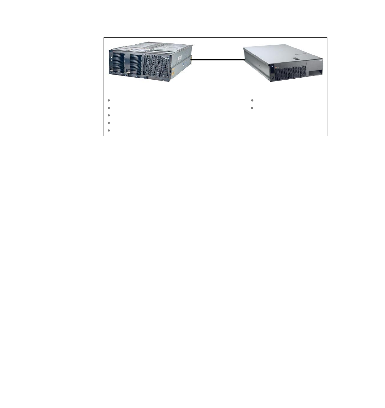
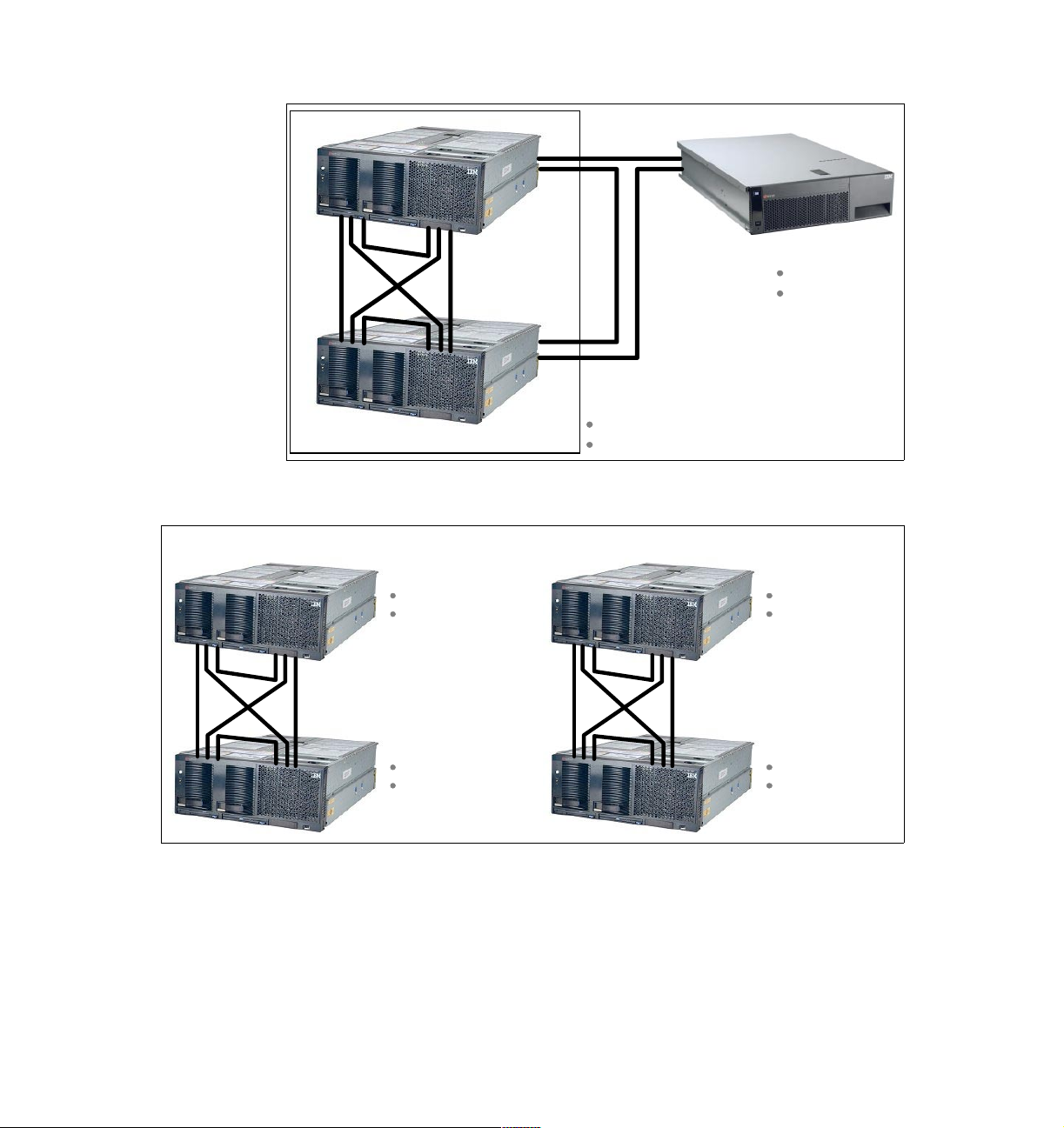
In addition to the single-node configurations, three additional two-node
configurations are possible:
A single 16-way system comprised of two eight-way x440 nodes, as shown in
Figure 1-2 on page 5. This will be available in November 2002.
A single 12-way system comprised of an eight-way and a four-way x440, as
shown in Figure 1-3 on page 5. This will be available in early 2003.
A single eight-way system comprised of two four-way x440 nodes, as shown
in Figure 1-3 on page 5. This will be available in early 2003.
Each of these configurations can optionally also have an RXE-100 attached (see
Figure 1-2 on page 5 for an example).
4 IBM ^ xSeries 440 Planning and Installation Guide
Page 19
RXE expansion
connections
SMP expansion
connections
One 16-way complex
Each xSeries 440 has:
Eight CPUs
4-64 GB memory
Figure 1-2 16-way server configuration using two eight-way x440 nodes
RXE-100
6 PCI-X slots
12 PCI-X slots
One eight-way complex
x440 node 1:
Four CPUs
2-32 GB memory
SMP expansion
connections
x440 node 2:
Four CPUs
2-32 GB memory
Figure 1-3 Eight-way and 12-way two-node configurations
One 12-way complex
x440 node 1:
Eight CPUs
4-64 GB memory
SMP expansion
connections
x440 node 2:
Four CPUs
2-32 GB memory
Chapter 1. Technical description 5
Page 20

1.2 System partitioning
Partitioning is the ability to divide a system to support multiple operating system
images simultaneously. The benefits of system partitioning include:
Hardware consolidation
Software migration and coexistence
Version control
Development, testing and maintenance
Workload isolation
Resource optimization around a particular application and operating system
combination
Independent backup and recovery on a partition basis
There are two types of system partitioning: physical partitioning
(hardware-based, but not yet available) and logical partitioning (software-based,
enabled with VMware ESX Server):
Logical partitioning
Using logical partitioning, administrators can partition a multinode complex at
the individual processor level (with associated memory, I/O and other required
resources) or even lower (that is, multiple partitions per processor) without
shutting down and restarting the hardware and software.
VMware ESX Server V1.5 supports one to eight partitions per CPU, up to a
maximum total of 64 partitions. For example, in an eight-way server, you can
have between eight partitions and 64 partitions. In V1.5, a partition cannot
span multiple CPUs, but a partition can be allocated a fraction of a CPU,
down to 1/8th of a CPU.
ESX Server virtualizes the resources of the x440 and is the closest that
Intel-based servers have come to date to the LPAR implementation of zSeries
mainframes.
When workload demands change, you can reassign resources from one
logical partition to another without having to shut down and restart the
system. ESX Server does not, however, support hot-adding of hardware
(such as disks and adapters).
For more information on ESX Server, see the redbook
with the IBM
3.5.7, “VMware ESX Server” on page 98.
Physical partitioning
This form of partitioning is available in 4Q 2002 with the release of System
Partition Manager, a plug-in for IBM Director.
6 IBM ^ xSeries 440 Planning and Installation Guide
^
xSeries 440 and VMware ESX Server
Server Consolidation
, SG24-6852 and
Page 21

With physical partitioning, a single multinode server complex can
simultaneously run multiple instances of one operating system in separate
partitions, as well as multiple versions of an operating system or even
different types of operating systems. The components of the server (for
example memory, CPUs, and I/O) are physically divided, under the control of
the server’s firmware and IBM Director.
The server can have up to two nodes, each capable of running its own
operating system and applications, all running simultaneously. A partition can
also span nodes, even to the point of having all four nodes serving one
operating system. Each node can be managed independently by IBM
Director.
See 5.2, “System Partition Manager” on page 150 for details.
1.3 IBM XA-32 chipset
The IBM XA-32 chipset is the product name describing the chipset developed
under the code name “Summit” and implemented on the IA-32 platform. A
product of the IBM Microelectronics Division in Austin, Texas, the XA-32 chipset
is fabricated using the latest in copper technology and is composed of the
following components:
Memory controllers — one memory controller, code named “Cyclone”, per
four-way located within the SMP Expansion Module
Processor/cache controllers — one processor and cache controller, code
named “Tw i s t er ”, per eight-way located within the SMP Expansion Module
PCI bridges — two PCI bridges, code named “Winnipeg”, per x440 located on
the centerplane and the I/O board that control both the PCI-X and Remote I/O
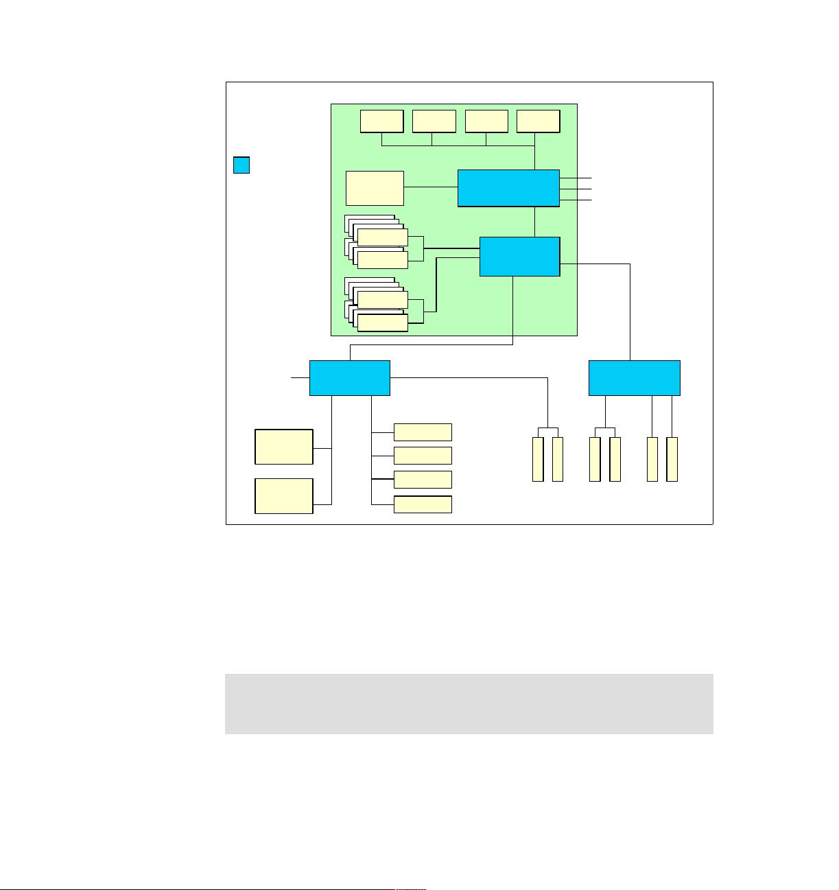
Figure 1-4 on page 8 shows the various IBM XA-32 components in a four-way
x440 configuration.
Chapter 1. Technical description 7
Page 22
CEC 1
CPU 1 CPU 2 CPU 3 CPU 4
IBM XA-32
core chipset
RXE
Expansion
Port A
(1 GBps)
Ultra160
SCSI
Gigabit
Ethernet
400 MHz
32 MB
L4 cache
SDRAM
SDRAM
SDRAM
SDRAM
PCI bridge PCI bridge
3.2 GBps
3.2 GBps
3.2
GBps
100MHz
4-way
interleave
33 MHz66 MHz
Video
USB
Kbd/Ms
RSA
3.2 GBps
Processor &
cache controller
3.2 GBps
Memory
controller
2 GBps
Bus A66 MHz
64-bit
66 MHz
SMP Expansion
Ports (3.2GBps)
2 GBps
B-100
64-bit
100 MHz
133 MHz
Figure 1-4 xSeries 440 system block diagram — one SMP Expansion Module
D-133C-133
64-bit
The component that contains the CPUs, processor/cache controller, memory
controller, memory, and cache is called the SMP Expansion Module (or central
electronics complex—CEC). The Xeon MP-based models of the x440 ship with
one SMP Expansion Module with two or four CPUs and 2 GB or 4 GB of RAM.
The Xeon DP-based models have either two CPUs in one SMP Expansion
Module or four CPUs in two SMP Expansion Modules.
Tip: The terms central electronics complex, CEC, and SMP Expansion
Module
are used interchangeably in relation to the x440. We use SMP
Expansion Module in this redbook.
8 IBM ^ xSeries 440 Planning and Installation Guide
Page 23

The CPUs are connected together with a 100 MHz frontside bus, but supply data
at an effective rate of 400 MHz using the “quad-pump” design of the Intel
NetBurst architecture as described in 1.4.1, “Intel Xeon Processor MP” on
page 13. To ensure the processors are optimally used, the x440 has a 32 MB
XceL4 Server Accelerator Cache, comprised of 200 MHz DDR memory. This L4
system cache services all CPUs in an SMP Expansion Module.
Memory used in the x440 is standard 133 MHz ECC SDRAM DIMMs; however,
the 133 MHz DIMMs are run at 100 MHz (for parts availability reasons). With
2 GB DIMMs, up to 32 GB can be installed using all 16 DIMM sockets. The
memory is four-way interleaved so that the memory subsystem can supply data
fast enough to match the throughput of the CPUs. Four-way interleaving means
that DIMMs must be installed in matched fours and in specific DIMM sockets (see
3.1.2, “Memory” on page 65).
The second SMP Expansion Module can be installed when more than four Xeon
MP processors, or two Xeon DP processors, are required. This also enables the
system to have up to 64 GB of RAM, using 2 GB DIMMs. The block diagram with
two SMP Expansion Modules is shown in Figure 1-5 on page 10.
Note: When Xeon DP processors are used, only two CPUs can be installed in
each SMP Expansion Module. The processors are installed in CPU positions
1 and 4. Positions 2 and 3 must hold air baffles to maintain proper air flow.
Chapter 1. Technical description 9
Page 24
CEC 1
CEC 2
CPU 1 CPU 2 CPU 3 CPU 4
400 MHz
32 MB
L4 cache
SDRAM
SDRAM
SDRAM
SDRAM
RXE Expansion
Port A (1 GBps)
3.2 GBps
3.2 GBps
3.2
GBps
100 MHz
PCI bridge
Ultra160
SCSI
Gigabit
Ethernet
3.2 GBps
Processor &
cache controller
3.2 GBps
Memory
controller
2 GBps
33 MHz66 MHz
Video
USB
Kbd/Ms
RSA
SMP Expansion
Ports (3.2GBps)
RXE
Expansion
Port B
(1 GBps)
Bus A66 MHz
cache controller
controller
2 GBps
64-bit
66 MHz
3.2 GBps
Processor &
3.2 GBps
Memory
PCI bridge
B-100
64-bit
100 MHz
3.2 GBps
3.2 GBps
3.2
GBps
100 MHz
64-bit
133 MHz
CPU 1CPU 2CPU 3CPU 4
400 MHz
32 MB
L4 cache
SDRAM
SDRAM
SDRAM
SDRAM
D-133C-133
IBM XA-32
core chipset
Figure 1-5 xSeries 440 system block diagram — two SMP Expansion Modules
When two SMP Expansion Modules are installed, they are connected together
using two 3.2 GBps SMP Expansion Ports. The third scalability port is not used in
this single-node eight-way configuration.
The two PCI bridges in the XA-32 chipset provide support for 33, 66, 100, and
133 MHz devices using four PCI-X buses (labeled A-D in Figure 1-5). This is
discussed further in 1.8, “PCI subsystem” on page 23.
The PCI bridge also has a 1 GBps bi-directional Remote Expansion I/O port
(RXE port) for connectivity to the RXE-100 enclosure. This port is labeled “RXE
Expansion Port A” in both Figure 1-4 on page 8 (four-way) and Figure 1-5
(eight-way). The RXE-100 provides up to an additional 12 PCI-X slots. When the
second SMP Expansion Module is installed to form an eight-way system
(Figure 1-5), the second RXE port, labeled “RXE Expansion Port B”, connects to
the memory controller of the second SMP Expansion Module.
10 IBM ^ xSeries 440 Planning and Installation Guide
Page 25
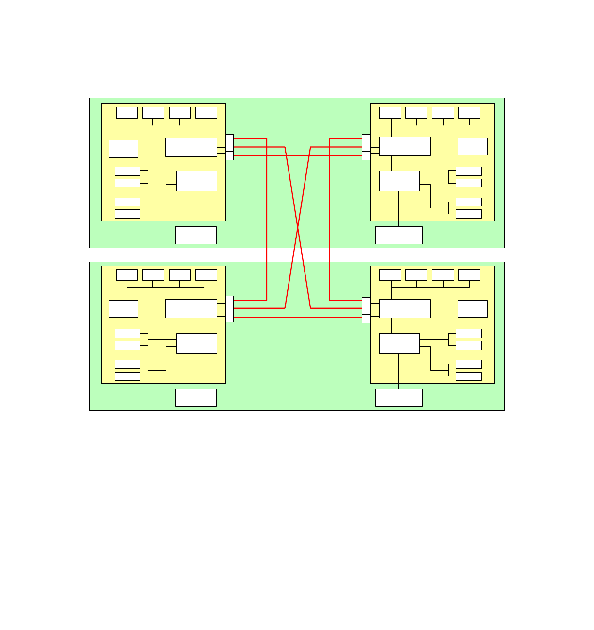
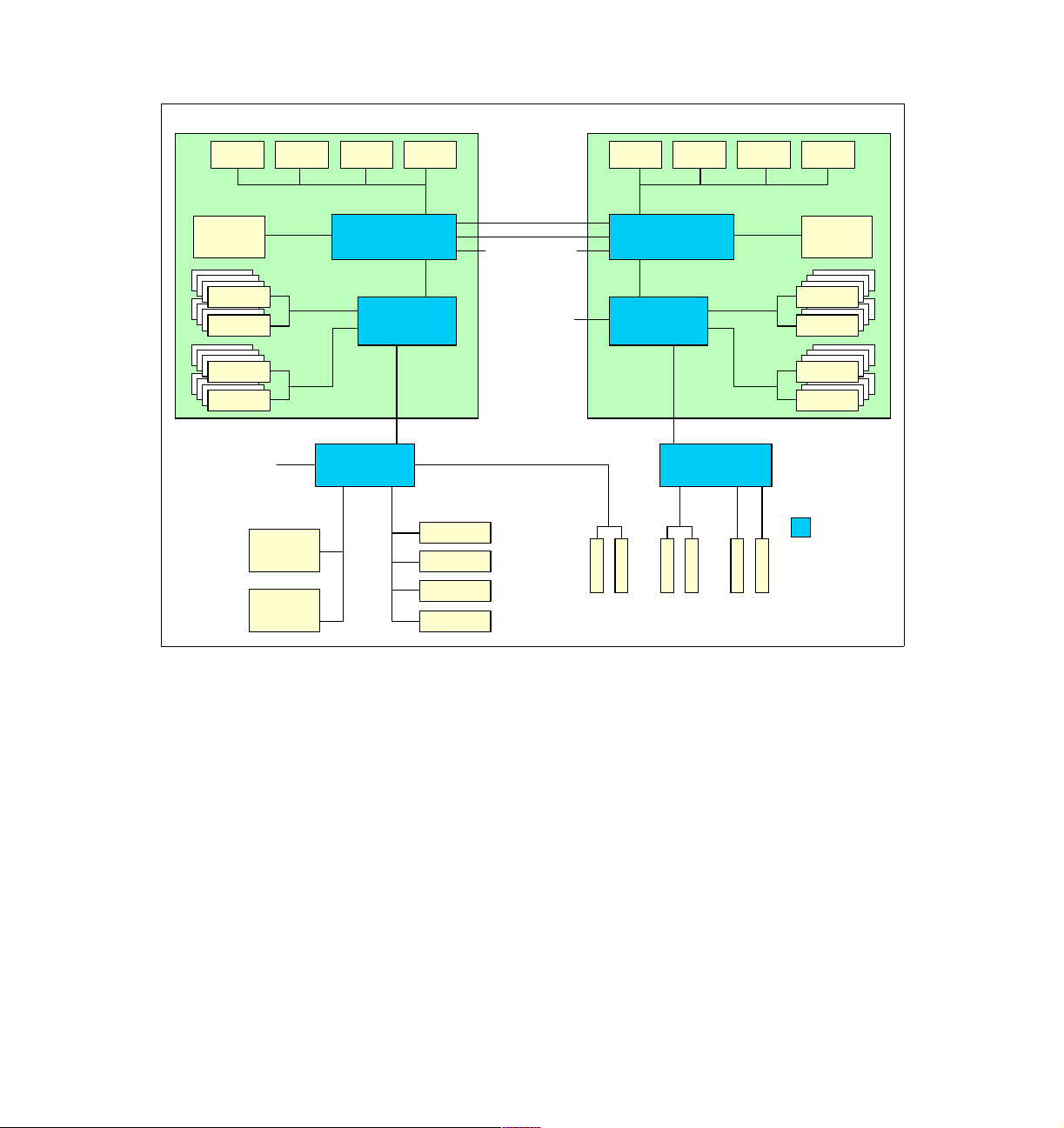
As of November 2002, you can connect two x440 servers together to form one
16-way complex. The two x440 nodes are connected together using all three
SMP Expansion Ports as shown in Figure 1-6.
CPU 1 CPU 2 CPU 3 CPU 4
32 MB
L4 cache
SDRAM
SDRAM
SDRAM
SDRAM
x440 Node 1
CPU 1 CPU 2 CPU 3 CPU 4
32 MB
L4 cache
SDRAM
SDRAM
SDRAM
SDRAM
Processor &
cache controller
Memory
controller
PCI bridge
Processor &
cache controller
Memory
controller
CEC 1 CEC 2
1
2
3
CEC 1
1
2
3
CEC 2
SMP Expansion
Ports (3.2GBps)
1
2
3
1
2
3
Processor &
cache controller
Memory
controller
PCI bridge
Processor &
cache controller
Memory
controller
CPU 1CPU 2CPU 3CPU 4
32 MB
L4 cache
SDRAM
SDRAM
SDRAM
SDRAM
CPU 1CPU 2CPU 3CPU 4
32 MB
L4 cache
SDRAM
SDRAM
SDRAM
SDRAM
x440 Node 2
PCI bridge
Figure 1-6 16-way configuration (four SMP Expansion Modules)
The rear panel of the x440, indicating the location of the SMP Expansion Ports
and RXE Expansion Ports, is shown in Figure 1-7 on page 12.
PCI bridge
Chapter 1. Technical description 11
Page 26
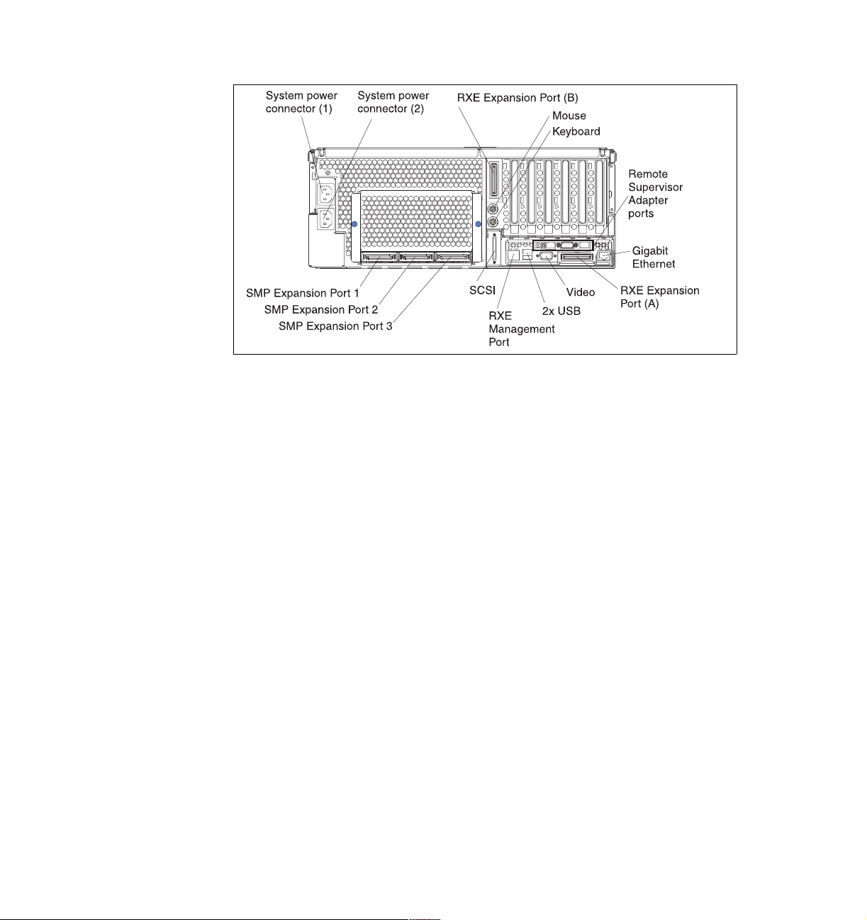
Figure 1-7 Rear panel of the xSeries 440 (one SMP Expansion Module installed)
1.4 Processors
The x440 models use one of the following processors:
Xeon Processor MP (“Gallatin”)
Xeon Processor MP (“Foster”)
Xeon Processor DP (“Prestonia”)
The Xeon MP models of the x440 come with two or four processors installed in
the standard SMP Expansion Module. Up to four processors are supported in the
standard module and, with the addition of a second SMP Expansion Module, up
to eight processors can be installed in an x440.
The x440 entry-level systems can be ordered with either two Xeon DP
processors in a single SMP Expansion Module or with four Xeon DP processors
in two SMP Expansion Modules. There is no further upgrade beyond four Xeon
DP processors, other than replacing them with Xeon MP processors.
See 3.1.1, “Processors” on page 64 for further discussion about what you should
consider before implementing an x440 solution.
12 IBM ^ xSeries 440 Planning and Installation Guide
Page 27

1.4.1 Intel Xeon Processor MP
The Xeon Processor MP (code named “Foster” or “Gallatin”) returns to the ZIF
socket design of the original Pentium processor, instead of the Slot 2 cartridge
design of the Pentium III Xeon processors. This smaller form factor means that
the x440 can have up to eight processors in a 4U node.
The Xeon MP processor has three levels of cache, all of which are on the
processor die:
Level 3 cache is equivalent to L2 cache on the Pentium III Xeon. Foster
processors in the x440 models contain either 512 KB or 1 MB of L3 cache.
Gallatin processors contain either 1 MB or 2 MB or L3 cache.
Level 2 cache is equivalent to L1 cache on the Pentium III Xeon and is 256 KB
in size. The L2 cache implements the Advanced Transfer Cache technology,
which means L2-to-processor transfers occur across a 256-bit bus in only one
clock cycle.
A new level 1 cache, 12 KB in size, is “closest” to the processor and is used to
store micro-operations (that is, decoded executable machine instructions) and
serves those to the processor at rated speed. This additional level of cache
saves decode time on cache hits. There is an additional 8 KB for data related
to those instructions, for a total of 20KB.
The x440 also implements a Level 4 cache as described in 1.6, “IBM XceL4
Server Accelerator Cache” on page 19.
Intel has also introduced a number of features associated with its newly
announced NetBurst micro-architecture. These are available in the x440,
including:
400 MHz frontside bus
The Pentium III Xeon processor has a 100 MHz frontside bus that equates to
a burst throughput of 800 MBps. With protocols such as TCP/IP, this has been
shown to be a bottleneck in high-throughput situations. The Xeon Processor
MP improves on this by using two 100 MHz clocks, out of phase with each
other by 90° and using both edges of each clock to transmit data. This is
shown in Figure 1-8.
100 MHz clock A
100 MHz clock B
Figure 1-8 Quad-pumped frontside bus
Chapter 1. Technical description 13
Page 28
This increases the performance of the frontside bus without the difficulty of
high-speed clock signal integrity issues. The end result is an effective burst
throughput of 3.2 GBps, which can have a substantial impact, especially on
TCP/IP-based LAN traffic.
Hyper-Threading
Hyper-Threading technology enables a single physical processor to execute
two separate code streams (threads) concurrently. To the operating system, a
processor with Hyper-Threading appears as two
which has its own architectural state - that is, its own data, segment, and
control registers and its own advanced programmable interrupt controller
(APIC).
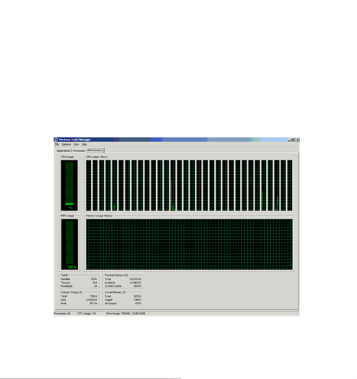
For example, Figure 1-9 shows a 16-way x440 complex running Datacenter
Server with Hyper-Threading enabled.
logical processors, each of
Figure 1-9 Datacenter sees 32 processors when Hyper-Threading is enabled on a 16-way configuration
14 IBM ^ xSeries 440 Planning and Installation Guide
Page 29

Each logical processor can be individually halted, interrupted, or directed to
execute a specified thread, independently from the other logical processor on
the chip. Unlike a traditional two-way SMP configuration that uses two
separate physical processors, the logical processors share the execution
resources of the processor core, which include the execution engine, the
caches, the system bus interface, and the firmware.
Note: Hyper-Threading is disabled by default on the x440. This is because
of a known bug in Windows 2000 Advanced Server. If Hyper-Threading is
enabled on an eight-way server, then the Windows 2000 Advanced Server
will trap (blue screen) during installation. This problem does not affect other
supported operating systems.
Hyper-Threading technology is designed to improve server performance by
exploiting the multi-threading capability of operating systems, such as
Windows .NET and Linux, and server applications, in such a way as to
increase the use of the on-chip execution resources available on these
processors.
Fewer or slower processors usually yield the best gains from
Hyper-Threading because there is a greater likelihood that the software can
spawn sufficient numbers of threads to keep both paths busy. The following
performance gains are likely:
– Two physical processors: 15-25% performance gain
– Four physical processors: 1-13% gain
– Eight physical processors: 0-5% gain
Tests have found that software often limits SMP scalability, but customers
should expect improved results as software matures. Best-case applications
today are:
– Databases
– Java
– Web servers
– E-mail
Note: Microsoft licensing of the Windows Server operating systems is by
number of processors (four-way for Server, eight-way for Advanced Server,
32-way for Datacenter Server). Therefore, the appearance of twice as many
logical processors can potentially affect the installation of the operating
system. See 1.12, “Operating system support” on page 28 for details.
For more information about Hyper-Threading, see:
http://www.intel.com/technology/hyperthread/
Chapter 1. Technical description 15
Page 30

Advanced Dynamic Execution
The Pentium III Xeon processor has a 10-stage pipeline. However, the large
number of transistors in each pipeline stage means that the processor is
limited to speeds under 1 GHz, due to latency in the pipeline.
The Xeon Processor MP has a 20-stage pipeline, which can hold up to 126
concurrent instructions in flight and up to 48 reads and 24 writes active in the
pipeline. The lower complexity of each stage also means that future clock
speed increases are possible.
It is important to note, however, that the longer pipeline means that it now
takes more clock cycles to execute the same instruction when compared to
the Pentium III Xeon.
Comparing the Xeon Processor MP with the Pentium III Xeon and current
operating systems (Windows 2000, Linux with 2.4 kernel), good rules of
thumb are:
– 1.5 GHz Xeon Processor MP/512 KB L3
MB L2 Xeon
– 1.6 GHz Xeon Processor MP/1 MB L3
MB L2 Xeon
The next generations of operating systems will likely improve performance of
the MP processor as they take advantage of the NetBurst architecture. These
include Windows .NET and the Linux 2.5/2.6 kernels.
For more information about the features of the Xeon Processor MP, go to:
http://www.intel.com/design/xeon/xeonmp/prodbref
1.4.2 Intel Xeon Processor DP
The Xeon DP is similar to the Xeon MP and is also based on the Intel NetBurst
micro-architecture. The Xeon DP was designed by Intel to be suitable only in
uniprocessor and two-way SMP processor systems. However, with the use of the
IBM XA-32 chipset, the x440 can have up to four Xeon DP processors installed.
The Xeon DP models of the x440 models use 2.4 GHz processors, part
37L3533.
The key differences between the processors are listed in Table 1-2.
Table 1-2 Differences between the Xeon DP and the Xeon MP
≈ 5-20% faster than 900 MHz 2
≈ 15-35% faster than 900 MHz 2
Feature Xeon Processor DP Xeon Processor MP
Maximum CPUs per SMP Expansion Module Two Four
Maximum CPUs per x440 node Four Eight
16 IBM ^ xSeries 440 Planning and Installation Guide
Page 31

Feature Xeon Processor DP Xeon Processor MP
Supported in multi-node configurations No Yes
Core frequency (x440 models) 2.4 GHz 1.4, 1.5, 1.6, 1.9, or 2.0 GHz
Level 2 cache 512 KB 256 KB
Level 3 cache None 512 KB, 1 MB or 2 MB
For more information about the features of the Xeon Processor DP, go to:
http://www.intel.com/design/xeon/prodbref
1.5 SMP Expansion Module
The SMP Expansion Module is the central electronics complex that contains the
processors, memory, L4 system cache, and respective controllers for these
components. The base x440 system includes one SMP Expansion Module. Each
SMP Expansion Module contains slots for up to four Xeon MP processors (or two
Xeon DP processors) and 16 DIMMs.
There are two SMP Expansion Module part numbers for x440 models:
32P8340 is used in Xeon MP models. It is “unpopulated”, which means it
does not contain any processors or memory. Any of the support Xeon MP
processors can be installed in it.
71P7919 is used in Xeon DP models. It contains two 2.4 GHz Xeon DP
processors and VRMs, and is used to upgrade a two-way Xeon DP x440 to a
four-way configuration.
71P7919 is also compatible with Xeon MP processors. If you wish to upgrade
your Xeon DP-based x440 to use Xeon MP processors, you can simply
replace the processors and VRMs with supported Xeon MP processors.
Note: Information about the SMP Expansion Modules to be used in
Gallatin-based systems (or existing systems you wish to upgrade to Gallatin
processors) was not available at the time of publication.
The SMP Expansion Module is installed from the top of the server and mounts to
the side of the centerplane using two levers on the top, as shown in Figure 1-10
on page 18. These same levers are used to remove the top of the SMP
Expansion Module when adding additional processors or memory.
Chapter 1. Technical description 17
Page 32

Locking
levers
Tip: Be careful when removing or installed the SMP Expansion Modules,
because you may damage the center plane. See tip H176162 for details:
http://www.pc.ibm.com/qtechinfo/MIGR-43675.html
SMP Expansion
Module cover
See-through hinged doors
for DIMM access
Connects to
center plane
this side
CPU 1
DIMM sockets
Figure 1-10 SMP Expansion Module
Each SMP Expansion Module also contains 16 DIMM slots to take the memory
up to a maximum of 64 GB per node (using 2 GB DIMMs) and an additional 32
MB of Level 4 system cache for a maximum of 64 MB per node.
When two SMP Expansion Modules are installed, they are connected together
using two 3.2 GBps SMP Expansion Ports (also known as scalability ports).
Using two connections improves throughput beyond that of one connection and
provides load balancing. The third scalability port is not used in this single-node
eight-way configuration.
Each SMP Expansion Module is also equipped with the following LEDs for Light
Path Diagnostics:
Each DIMM
Each CPU
Each VRM
SMP Expansion Module board
Handle
CPU 3
VRM
XceL4 cache
CPU 4
CPU 2
18 IBM ^ xSeries 440 Planning and Installation Guide
Page 33

1.6 IBM XceL4 Server Accelerator Cache
Integrated into each SMP Expansion Module is 32 MB of high-speed Level 4
cache (see Figure 1-10). This XceL4 Server Accelerator Cache provides the
necessary extra level of cache to alleviate the bottlenecks caused by memory
latency across the scalability port.
Cache memory is two-way interleaved 200 MHz DDR memory and is faster than
standard memory because it is directly connected to the memory controller and
does not have additional latency associated with the large fan-out necessary to
support the 16 DIMM slots.
Initial tests have shown the XceL4 cache has improved overall system
performance up to 20% on various applications.
1.7 System memory
The Xeon MP models of the x440 have 2 GB or 4 GB of RAM standard,
implemented as four PC133 ECC SDRAM DIMMs (four 512 MB or four 1 GB
DIMMs). There are 16 DIMM sockets (two ports of eight) in each of the two SMP
Expansion Modules for a total of 32 sockets. Using 2 GB DIMMs, this means that
each x440 can have up to 64 GB RAM.
See 3.1.2, “Memory” on page 65 for further discussion of how memory is
implemented in the x440 and what you should consider before an x440
installation.
There are a number of advanced features implemented in the x440 memory
subsystem, collectively known as
Memory ProteXion
Memory ProteXion, also known as “redundant bit steering”, is the technology
behind using redundant bits in a data packet to provide backup in the event of
a DIMM failure.
Currently, other industry-standard servers use 8 bits of the 72-bit data packets
for ECC functions and the remaining 64 bits for data. However, because the
x440 uses four-way interleaved memory, it needs only 6 bits to perform the
same ECC functions, thus leaving 2 bits free (Figure 1-11 on page 20).
Active Memory:
Chapter 1. Technical description 19
Page 34

72 Bit DIMM
2 bits
64 bits
Data
Figure 1-11 Memory ProteXion
6 bits
ECC
Spare
In the event that a chip failure on the DIMM is detected by memory scrubbing,
the memory controller can re-route data around that failed chip through the
spare bits (similar to the hot-spare drive of RAID array). It can do this
automatically without issuing a Predictive Failure Analysis (PFA) or Light Path
Diagnostics alert to the administrator. After the second DIMM failure, PFA and
Light Path Diagnostics alerts would occur on that DIMM as normal.
Memory scrubbing
Memory scrubbing is an automatic daily test of all the system memory that
detects and reports memory errors that might be developing before they
cause a server outage.
Memory scrubbing and Memory ProteXion work in conjunction with each
other, but they do not require memory mirroring (as described below) to be
enabled to work properly.
When a bit error is detected, memory scrubbing determines if the error is
recoverable or not. If it is recoverable, Memory ProteXion is enabled and the
data that was stored in the damaged locations is rewritten to a new location.
The error is then reported so that preventative maintenance can be
performed. As long as there are enough good locations to allow the proper
operation of the server, no further action is taken other than recording the
error in the error logs.
If the error is not recoverable, then memory scrubbing sends an error
message to the Light Path Diagnostics, which then turns on the proper lights
and LEDs to guide you to the defective DIMM. If memory mirroring is enabled,
then the mirrored copy of the data in the damaged DIMM is used until the
system is powered down and the DIMM replaced.
20 IBM ^ xSeries 440 Planning and Installation Guide
Page 35

Memory mirroring
Memory mirroring is roughly equivalent to RAID-1 in disk arrays, in that
memory is divided in two ports and one port is mirrored to the other half (see
Figure 1-12). If 8 GB is installed, then the operating system sees 4 GB once
memory mirroring is enabled (it is disabled in BIOS by default). All mirroring
activities are handled by the hardware without any additional support required
from the operating system.
Port 1 Port 2
Figure 1-12 Memory DIMMs are divided into two ports
When memory mirroring is enabled (see 4.1.2, “Enabling memory mirroring”
on page 108), the data that is written to memory is stored in two locations.
One copy is kept in the port 1 DIMMs, while a second copy is kept in the
port 2 DIMMs. During the execution of the read command, the data is read
from the DIMM with the least amount of reported memory errors through
memory scrubbing.
If memory scrubbing determines the DIMM is damaged beyond use, read and
write operations are redirected to the partner DIMM in the other port. Memory
scrubbing then reports the damaged DIMM and the Light Path Diagnostics
display the error. If memory mirroring is enabled, then the mirrored copy of the
Chapter 1. Technical description 21
Page 36

data in the damaged DIMM is used until the system is powered down and the
DIMM replaced.
Certain restrictions exist with respect to placement and size of memory
DIMMs when memory mirroring is enabled. These are discussed in “Memory
mirroring” on page 67.
Chipkill memory
Chipkill is integrated into the XA-32 chipset and does not require special
Chipkill DIMMs. Chipkill corrects multiple single-bit errors to keep a DIMM
from failing. When combining Chipkill with Memory ProteXion and Active
Memory, the x440 provides very high reliability in the memory subsystem.
Chipkill memory is approximately 100 times more effective than ECC
technology, providing correction for up to four bits per DIMM (eight bits per
memory controller), whether on a single chip or multiple chips.
If a memory chip error does occur, Chipkill is designed to automatically take
the inoperative memory chip offline while the server keeps running. The
memory controller provides memory protection similar in concept to disk array
striping with parity, writing the memory bits across multiple memory chips on
the DIMM. The controller is able to reconstruct the “missing” bit from the failed
chip and continue working as usual.
Chipkill support is provided in the memory controller and implemented using
standard ECC DIMMs, so it is transparent to the operating system.
In addition, to maintain the highest levels of system availability, if a memory error
is detected during POST or memory configuration, the server can automatically
disable the failing memory bank and continue operating with reduced memory
capacity. You can manually re-enable the memory bank after the problem is
corrected via the Setup menu in BIOS.
Memory mirroring, Chipkill, and Memory ProteXion provide multiple levels of
redundancy to the memory subsystem. Combining Chipkill with Memory
ProteXion enables up to two memory chip failures per memory port (8 DIMMs)
on the x440. An eight-way x440 with its four memory ports could sustain up to
eight memory chip failures. Memory mirroring provides additional protection with
the ability to continue operations with memory module failures.
1. The first failure detected by the Chipkill algorithm on each port doesn’t
generate a Light Path Diagnostics error, since Memory ProteXion recovers
from the problem automatically.
2. Each memory port could then sustain a second chip failure without shutting
down.
3. Provided that memory mirroring is enabled, the third chip failure on that port
would send the alert and take the DIMM offline, but keep the system running
out of the redundant memory bank.
22 IBM ^ xSeries 440 Planning and Installation Guide
Page 37

Note: The ability to hot-replace a failed DIMM or hot-add additional DIMMs are
currently not supported.
1.8 PCI subsystem
As shown in Figure 1-4 on page 8, there are six PCI-X slots internal to the x440:
Two 133 MHz slots, which accept 32 or 64-bit, 3.3 V, PCI or PCI-X adapters,
from 33-133 MHz
Two 100 MHz slots, which accept 32 or 64-bit, 3.3 V, PCI or PCI-X adapters,
from 33-100 MHz
Two 66 MHz slots, which accept 32 or 64-bit, 3.3 V, 33 or 66 MHz, PCI or
PCI-X adapters
See 3.1.3, “PCI slot configuration” on page 68 for details on what adapters are
supported and in what combinations.
The PCI subsystem also supplies these I/O devices:
Two Wide Ultra 160 SCSI ports, one internal and one external (Adaptec
AIC-7899 chipset)
Gigabit Ethernet port (Broadcom 5700 chipset)
The x440 was the first xSeries server to offer a Gigabit Ethernet controller
integrated standard in the system. The x440 includes a single-port Broadcom
BCM5700 10/100/1000 Base-T MAC (Media Access Controller) on a PCI
64-bit 66 MHz bus.
The BCM5700 supports full and half-duplex performance at all speeds
(10/100/1000 Mbps, auto-negotiated) and includes integrated on-chip
memory for buffering data transmissions to ensure the highest network
performance and dual onboard RISC processors for advanced packet parsing
and backwards compatibility with today's 10/100 network. The Broadcom
controller also includes software support for failover, layer-3 load balancing,
and comprehensive diagnostics.
Category 5 or better Ethernet cabling is required with RJ-45 connectors. If
you plan to implement a Gigabit Ethernet connection, ensure your network
infrastructure is capable of the necessary throughput to match the server’s I/O
capacity.
SVGA with 8 MB video memory (S3 Savage4 Pro chipset)
Three USB ports (one on front panel, two on rear)
Remote Supervisor Adapter (RS-485 ASM interconnect bus, 10/100 Ethernet
and serial ports)
Chapter 1. Technical description 23
Page 38

Note: There are no parallel or serial ports on the x440. For serial connections,
use the USB to Serial Adapter, part number 10K3661, as described in 3.2.4,
“Serial connections” on page 83.
With the addition of an RXE-100 Remote Expansion Enclosure, you can connect
an additional six or 12 PCI-X adapters to the x440. See 3.2.3, “Remote
Expansion Enclosure” on page 78 for details.
Note: Currently, only one RXE-100 can be connected to an x440 configuration.
For configurations up to eight-way (that is, single chassis), connectivity is using
one RXE Expansion Port and cable. The dual-chassis 16-way configuration uses
two redundant RXE cables. This is described in detail in 3.2.3, “Remote
Expansion Enclosure” on page 78.
1.9 Redundancy
The x440 has the following redundancy features to maintain high availability:
Four hot-swap multi-speed fans
With four hot-swap redundant fans, the x440 has adequate cooling for each of
its major component areas. There are two fans located at the front of the
server that direct air through the SMP Expansion Modules. These fans are
accessible from the top of the server without having to open the system
panels. In the event of a fan failure, the other fan will speed up to continue to
provide adequate cooling until the fan can be hot-swapped by the IT
administrator.
The other two fans are located just behind the power supplies and provide
cooling for the I/O devices. Similar to the SMP Expansion Module fans, these
fans will speed up in the event that one should fail to compensate for the
reduction in air flow. In general, failed fans should be replaced within 24 hours
following failure.
Important: Due to airflow requirements, fans should not be removed for
longer than two minutes. The fan compartments need to be fully populated
even if the fan is defective. Therefore, remove a defective fan only when a
new fan is available for immediate replacement.
Two hot-swap power supplies with separate power cords.
Note: For large configurations, redundancy is achieved only when connected
to a 220 V power supply. See 3.8, “Power considerations” on page 103 for
details.
24 IBM ^ xSeries 440 Planning and Installation Guide
Page 39

Two hot-swap hard disk drive bays. An optional ServeRAID adapter can be
configured to form a RAID-1 disk array for the operating system.
The memory subsystem has a number of redundancy features, including
memory mirroring, as described in 1.7, “System memory” on page 19.
The layout of the front panel of the x440, showing the location of the drive bays,
power supplies and fans, is shown in Figure 1-13.
Hot-swap fans
Power-on light
Power button
Reset button
Hot swap
power supplies
Hot swap
drive bays
Diskette drive
CD-ROM drive
Light Path Diagnostics
panel (pulls out)
System-error light (amber)
Information light (amber)
SCSI activity light (green)
Locator light (blue)
USB port
Figure 1-13 Front panel of the xSeries 440
1.10 Light Path Diagnostics
To limit the need to slide the server out of the rack to diagnose problems, a new
Light Path Diagnostics panel has been added to the front of the x440. This panel
can be ejected from the server to view all Light Path Diagnostics-monitored
server subsystems. In the event that maintenance is then required, the customer
can slide the server out from the rack and using the LEDs, find the failed or failing
component.
As illustrated in Figure 1-14 on page 26, Light Path Diagnostics is able to monitor
and report on the health of CPUs, main memory, hard disk drives, PCI-X and PCI
slots, fans, power supplies, VRMs, and the internal system temperature.
Chapter 1. Technical description 25
Page 40

C
P
U
V
R
M
MEMORY
DA
S
D
N
M
I
B
O
A
R
D
E
V
E
N
T
L
O
G
FA
N
P
O
W
E
R
S
U
P
P
L
Y
P
C
I
B
U
S
2
1
N
O
N
R
E
D
OV
E
R
S
P
E
C
T
E
M
P
R
E
M
I
N
D
i
!
CPU
MEMORY
DASD
PCI-X BUS
FAN
1
POWER
SUPPLY
2
TEMP
Light Path
Diagnostics™
NMI
BOARD
EVENT LOG
VRM
NON REDUND
OVER SPEC
REMIND
Figure 1-14 Light Path Diagnostics panel on the x440
The Light Path Diagnostics on the x440 has three levels:
1. Level 1 is the pop-out panel as shown in Figure 1-14.
2. For further investigation, there are Light Path Diagnostics LEDs visible
through the top of the server. This requires the server to be slid out of the
rack.
3. For the third level of diagnostics, LEDs on the planar indicates the component
causing the error.
The pop-out panel (Figure 1-14) also has a Remind button. This places the front
panel system-error LED into remind mode, which means it flashes briefly every 2
seconds. By pressing the button, you acknowledge the failure but indicate that
you will not take immediate action. If a new failure occurs, the system-error LED
will turn on again. The system-error LED remains in the Remind mode until one
of the following situations occurs:
All known problems are resolved
The system is restarted
A new problem occurs, at which time it then is illuminated continuously
26 IBM ^ xSeries 440 Planning and Installation Guide
Page 41

1.11 Remote Supervisor Adapter
The x440 includes a Remote Supervisor Adapter (RSA), which is positioned
horizontally in a dedicated PCI slot beneath the PCI-X adapter area of the
system.
Rear of x440
External power
supply
Error LED
(amber)
Figure 1-15 Remote Supervisor Adapter connectors
ASM interconnect
(RS-485) port
Power LED
(green)
10/100
Ethernet port
Management
COM port
The Remote Supervisor Adapter offers the following capabilities:
In-band and out-of-band remote server access and alerting through IBM
Director
Full Web browser support with no other software required
Enhanced security features
Graphics/text console redirection for remote control
Windows NT and 2000 blue screen capture
Dedicated 10/100 Ethernet access port
ASM interconnect bus for connection to other service processors
Serial dial in/out
E-mail, pager and SNMP alerting
Event log
Predictive Failure Analysis on memory, power, hard drives, and CPUs
Temperature and voltage monitoring with settable threshold
Light Path Diagnostics
Automatic Server Restart (ASR) for operating system and POST
Wake on LAN
Remote firmware update
LAN access
Alert forwarding
See the IBM Redbook
Implementing IBM Director Management Solutions
SG24-6188 for more information on the Remote Supervisor Adapter.
Chapter 1. Technical description 27
,
Page 42

In addition to these functions, the Remote Supervisor Adapter is an integral
component of the two-node x440 configurations. With the two-node 16-way
configuration, the adapters are used in the following way:
The adapters in both systems are each assigned an IP address (on the same
subnetwork)
The adapters are connected via their Ethernet ports, either with a cross-over
cable, or on a hub or switch, as shown in Figure 3-6 on page 76.
One adapter is configured as the primary, and the other is configured as the
secondary.
Pressing the power button on either x440 will cause the adapters to power up
both nodes.
1.12 Operating system support
In line with the overall message of providing application flexibility to meet the
varying needs of our enterprise customers, the x440 is optimized for numerous
operating system and application solutions. Table 1-3 on page 29 lists the
supported operating systems for the x440. For the latest operating system
support information, go to:
http://www.pc.ibm.com/us/compat/nos/matrix.shtml
See 3.5, “Operating system considerations” on page 90 for further information on
operating system support on the x440.
Note: Windows 2000 Datacenter Server and VMware ESX Server are the only
operating systems currently supported on the 16-way x440 fixed configuration.
In the column titled Hyper-Threading Support in Table 1-3 on page 29:
None indicates the operating system does not recognize the logical
processors that Hyper-Threading enables.
Yes indicates that the operating system recognizes the logical processors and
can execute threads on them but is not optimized for Hyper-Threading.
Optimized indicates that the operating system recognizes the logical
processors and the operating system code has been designed to fully take
advantage of the technology.
28 IBM ^ xSeries 440 Planning and Installation Guide
Page 43

Table 1-3 x440 operating system support
Description Release SMP support
1
Windows 2000 Server SP2/3 Supports up to four-way Yes
Windows 2000 Advanced Server SP2/3 Supports up to eight-way Yes
Windows 2000 Datacenter Server SP3 Supports up to 32-way
2
Hyper-Threading
support
Ye s
Windows NT Enterprise Edition 4.0 Only supports four-way on the
None
x440
Hot-plug PCI not supported
Windows .NET Server 1Q/03 Supports up to two-way Optimized
Windows .NET Enterprise Server 1Q/03 Supports up to eight-way Optimized
Windows .NET Datacenter Server 1Q/03 Supports up to 32-way
NetWare 6.0 Supports up to 32-way
2
2, 3
Red Hat Linux Advanced Server 2.1 Supports up to eight-way
SuSE Linux Enterprise 8.0 Supports up to eight-way
VMware ESX Server 1.5 Supports up to 16-way
Supports up to one processor per
5
VM
4
4
Optimized
Ye s
Ye s
Ye s
None
Notes to Table 1-3:
1. While operating systems may support eight-way or larger systems, scalability
is a function of both the operating system and the application/workload. Few
applications are designed to take advantage of larger SMP systems.
2. x440 configurations with 16 processors and Hyper-Threading enabled are
seen as 32 processors under Windows 2000 Datacenter and Windows .NET.
Licensing of processors in Windows 2000 is based on physical and logical
processors combined, whereas Windows .NET licensing is based on physical
processors.
3. NetWare notes:
– NetWare 5.1 is currently not supported, but it should still install. See
RETAIN tip H176163 for details on a known shutdown problem:
http://www.pc.ibm.com/qtechinfo/MIGR-43679.html
Chapter 1. Technical description 29
Page 44

– With NetWare 6.0, the server may show extreme CPU utilization values
(for example, 13000%). This will be fixed with NetWare 6.0 Support Pack
2. See RETAIN tip H176060 at:
http://www.pc.ibm.com/qtechinfo/MIGR-43532.html
– Once supported, a multi-chassis configuration must be fully assembled
before installing NetWare. Novell doesn’t currently support adding chassis
after NetWare is installed.
4. Ongoing work will improve both Linux and key application scalability.
Currently, the general recommendation is to keep system size limited to
eight-way and below, and 16 GB and below. Work on scalability beyond
eight-way is in progress, and is likely to become available in early to
mid-2003.
5. VMware ESX Server 1.5 allows eight virtual machines per processor.
However, a virtual machine (VM) can consist of no more than one processor.
16-way support will require Version 1.5.1.
1.13 IBM Director
IBM Director is designed to manage all platforms in the Intel environment and
support a variety of operating systems.
IBM Director 3.1 supports IBM Enterprise X-Architecture capabilities, including
Remote I/O via the IBM RXE-100 Remote Expansion Enclosure and the new
Real Time Diagnostics feature of the x440. CIM-related enhancements include:
CIM instrumentation for Linux
Mass configuration of client CIM properties — Saves time by setting up and
configuring multiple systems as a group, rather than having to configure each
system individually
Hardware instrumentation using CIM — Enables RAID and systems
management hardware information and alerts to be passed up to higher-level
management packages as part of the IBM Director upward integration
modules (UIMs)
IBM Director 4.1 will support VMware ESX Server both at the VMware console
level and at the guest operating system level.
IBM Director includes server extensions that help administrators configure,
deploy, manage, and maintain your servers easily and effectively. IBM Director
Extensions include the following:
System Partition Manager — System Partition Manager provides a
graphical interface for creating static hardware partitions. It allows an
30 IBM ^ xSeries 440 Planning and Installation Guide
Page 45

administrator to configure a specific server (while it is offline) from a remote
system, prior to starting the operating system.
See 5.2, “System Partition Manager” on page 150 for more information.
Active PCI Manager — Active PCI Manager helps optimize I/O performance
by matching the PCI-X bus and card characteristics and offering guidance on
the best slots in which to install PCI and PCI-X adapters.
See 5.1, “Active PCI Manager” on page 130 for details.
Capacity Manager — Capacity Manager monitors critical server resources
such as processor utilization, disk capacity, memory usage and network
traffic. Using advanced artificial intelligence, it identifies bottlenecks for an
individual system, a group of systems, or a cluster, and recommends
upgrades to prevent diminished performance or downtime. Capacity Manager
can even identify latent bottlenecks and make recommendations for
preventive action. For example, Capacity Manager can predict hard disk drive
and memory shortages that might cause problems.
Because Capacity Manager features can help predict problems before they
occur, the administrator can perform proactive planning and schedule service
and upgrades before potential problems degrade performance.
Capacity Manager will be updated to support partitioning in the next release
of IBM Director, planned for the second half of 2002.
Cluster Manager — Cluster Manager allows an administrator to easily
identify, configure, and manage clustered servers using one graphical tool.
Administrators can be alerted via pager or e-mail about cluster events in
hardware, the operating system, and Microsoft Cluster Service (MSCS).
Alternatively, Cluster Manager can trigger recovery programs or others
automatically.
Management Processor Assistant — The Management Processor
Assistant (MPA) task, previously named the Advanced System Management
task, lets the administrator monitor critical subsystems as well as restart and
troubleshoot servers, even if a server has suffered a fatal error or is powered
off. This utility works in concert with the IBM family of systems management
processors and adapters described previously. IBM Director 3.1 added
management support for the RXE-100 Remote I/O unit.
Rack Manager — Rack Manager offers a drag-and-drop interface for easily
configuring and monitoring rack components using a realistic visual
representation of the rack and its components. It also provides detailed health
status information for the rack and its elements. IBM Director 3.1 added the
ability to drag-and-drop objects between racks.
RAID Manager — RAID Manager lets an administrator configure, monitor,
and manage ServeRAID subsystems without taking the server offline. IBM
Director 3.1 includes field replaceable unit (FRU) number reporting in alerts
Chapter 1. Technical description 31
Page 46

for RAID components and hard disk drives. This reduces labor and service
costs by providing replacement part information in the alert message so that
the correct part can be obtained for the service call.
Software Rejuvenation — In networked servers, software often exhibits an
increasing failure rate over time, due to programming errors, data corruption,
numerical error accumulation, etc. These errors can spawn threads or
processes that are never terminated, or they can result in memory leaks or file
systems that fill up over time. These effects constitute a phenomenon known
as “software aging”, which can lead to unplanned server outages. Advanced
IBM analytical techniques allow IBM Director Software Rejuvenation to
monitor trends and predict system outages based on the experience of
system outages on a given server. Alerts of this sort act as Predictive Failure
Analysis for software, giving an administrator the opportunity to schedule
servicing (rejuvenation) at a convenient time in advance of an actual failure
and avoid costly downtime.
Software Rejuvenation can be scheduled to reset all or part of the software
system with no need for operator intervention. When Software Rejuvenation
reinitializes a server, the server’s software failure rate returns to its initial lower
level because resources have been freed up and the cumulative effects of
numerical errors have been removed.
When Software Rejuvenation is invoked within a clustered environment,
cluster management failover services (such as Microsoft Cluster Services and
Microsoft Datacenter Server) may be used to stop the offending subsystem
and restart it on the same or another node in the cluster in a controlled
manner. In a clustered environment, xSeries servers can be set to fail over to
another server, then be reset by IBM Director without downtime.
IBM Director 3.1 includes a Trend Viewer feature to graphically monitor the
software aging process and an “application culprit” list that identifies the
applications most likely to be causing the aging.
System Availability — System Availability accurately measures
uptime/downtime for individual servers or groups of servers, and provides a
variety of graphical views of this information. This enables users to track the
improvements in their server availability in order to verify the benefits of the
systems management processes and tools. IBM Director 3.1 includes the
ability to distinguish between planned versus unplanned outages.
Electronic Service Agent — Electronic Service Agent enables the Director
server to contact IBM automatically in the event of a fault condition. Data
gathered by IBM Director that is relevant to the fault is included in the
message, in most cases allowing IBM service to respond to the condition
without the need for additional details. Once IBM has been notified of the
event, the course of action is the same as if a service call was placed
manually. Electronic Service Agent support requires registering the systems
32 IBM ^ xSeries 440 Planning and Installation Guide
Page 47

with IBM, including providing a contact name and phone number, and is
available for systems covered under warranty or maintenance agreements.
Electronic Service Agent currently requires the use of an analog phone line
and modem. Access via VPN may be possible in future releases.
See the IBM Redbook
Implementing IBM Director Management Solutions
SG24-6188 for details on IBM Director and its plug-ins.
,
Chapter 1. Technical description 33
Page 48

34 IBM ^ xSeries 440 Planning and Installation Guide
Page 49

Chapter 2. Positioning
In this chapter we discuss topics that help you understand how the x440 can be
useful to your business and what is the best configuration to use. The topics
covered are:
xSeries 440 application solutions
Why choose the x440
The benefits of system partitioning
Server consolidation
2
© Copyright IBM Corp. 2002. All rights reserved. 35
Page 50

2.1 xSeries 440 application solutions
The x440 is an ideal platform for customers running mission-critical applications.
There are a number of ways the x440 can be deployed in specific application
solution environments. These include:
Server consolidation
Enterprise applications
Infrastructure applications
Clustering
2.1.1 Server consolidation
Server consolidation is a process of centralizing business computing workloads
to reduce cost, complexity, network traffic, management overhead and, in
general, to simplify the existing IT infrastructure and provide a foundation for new
solution investment and implementation.
Server consolidation is discussed in detail in 2.4, “Server consolidation” on
page 51.
Server consolidation solutions can be divided into two groups: those where no
more than four-way SMP is needed, and those that will take advantage of more
CPUs.
Four-way configurations
The four-way configurations would most likely be good candidates for
traditional messaging/collaboration environments such as Microsoft
Exchange and Lotus Domino. These applications do not scale well beyond a
four-way SMP configuration. It is an optimal platform for customers who
intend to migrate from Exchange 5.5 to Exchange 2000 using new features of
Exchange 2000 such as the support for more databases. Many customers
have distributed Exchange and Lotus Domino sites, which is costly and
difficult to manage. Here, the x440 can be a very attractive platform to
consolidate distributed sites into a central site.
Many ISPs are running different Internet applications and mail systems on
several servers. In most cases, they run applications on several servers to get
better I/O. The four-way x440 server connected to an RXE-100 fulfills this
requirement and ISPs can continue servicing the customers by consolidating
to an x440 server.
Although many applications such as file, print, and terminal servers do not
scale well beyond two processors, the four-way x440 can be a good platform
on which to consolidate those distributed applications. For example, using
36 IBM ^ xSeries 440 Planning and Installation Guide
Page 51

VMware many file and print servers that are distributed around the enterprise
can be consolidated to a four-way x440 server, reducing the TCO.
Using logical partitioning with four-way configurations can produce a one-box
cluster solution for small-to-medium-sized businesses (SMB) that need to
protect their mission-critical applications and files. With this solution, SMB
customers can reduce their total cost of ownership and save money.
In addition, a four-way x440 can be a good platform for light ERP solutions
such as Navision.
Eight-way and 16-way configurations:
The eight-way and 16-way x440 is ideal for customers who want to
consolidate their enterprise applications (ERP, CRM, and SCM) or roll out
new enterprise applications. These configurations offer computing power,
high availability, and reliability, which are the main requirements when running
enterprise applications. The goal is to help customers to control their
expenses while establishing an environment that is easier to manage
because of fewer nodes.
The eight-way and 16-way configurations are solid platforms to be used for
consolidating database applications such as DB2, SQL Server, and Oracle.
For instance, a single database that spans multiple servers can be
consolidated to an eight-way x440 server or multiple databases on multiple
server can be consolidated to a 16-way x440 complex.
Many customers have multiple databases distributed on multiple sites and
they are planning to migrate to new database versions. This could be a very
costly and time-intensive process. The migration process needs to be well
planned and tested without any interruption of the business process. The
eight-way or 16-way can be an optimal platform for these customers. For
example, you can consolidate the distributed databases on multiple sites to a
16-way x440. Using logical partitioning on x440, you can build, test and
deploy many virtual databases on one physical server.
The main reasons to consolidate database applications are:
– Migration from older database versions to new versions getting the
advantages relating to availability, reliability and performance.
– Support for more databases. For instance, SQL Server 2000 can support
up to 32,767 open databases.
– Reducing the management costs of distributed database sites by
consolidating to an easy-to-manage central site.
In addition, using logical partitioning with eight-way and 16-way configurations
can produce a powerful server solution that is capable of hosting multiple
applications.
Chapter 2. Positioning 37
Page 52

2.1.2 Enterprise applications
Because enterprise applications such as ERP, SCM, CRM and BI work with the
most critical data of a business, x440 with its high-availability features is an ideal
server for these applications.
Enterprise Resource Planning
Enterprise Resource Planning (ERP) is an industry term for the broad set of
activities supported by multi-module application software that helps a
manufacturer or other business manage the important parts of its business,
including product planning, parts purchasing, maintaining inventories,
interacting with suppliers, providing customer service, and tracking orders.
ERP can also include application modules for the finance and human
resources aspects of a business. Typically, an ERP system uses or is
integrated with a relational database system.
The key operation areas of the x440 for ERP applications are:
– As an application server and as a database server with two-way servers
such as the x330 acting as Web servers.
– As an application server front-end to a pSeries or zSeries database
server, due to the fact that ERP applications involve integration across
heterogeneous environments.
– Using partitionable x440 servers to deploy ERP applications within a
single large-scale server, which could be an attractive solution for SMB
customers offering them new levels of manageability as it relates to their
ERP implementation.
Key server attributes for ERP applications are availability, scalability, and
performance. The x440, with its Enterprise X-Architecture technology such as
XpandOnDemand capability, Active Memory, and XceL4 server accelerator
cache, is a robust basis to build and implement successful ERP solutions.
Key ERP software vendors include SAP, Oracle, PeopleSoft, Microsoft, JD
Edwards, Baan/Invensys, and Navision.
Supply chain management
Supply chain management (SCM) is the oversight of materials, information,
and finances as they move in a process from supplier to manufacturer to
wholesaler to retailer to consumer. Supply chain management involves
coordinating and integrating these flows both within and among companies.
The x440 is a preferred platform for SCM management applications. The
x440 offers a range of leading technologies that will help to deliver the uptime
required for business-critical applications at the lowest price/performance
ratio. The x440 covers all high-availability features for customers looking for
servers to power their SCM solutions. Also, the x440 can be considered as an
38 IBM ^ xSeries 440 Planning and Installation Guide
Page 53

application server or in a heterogeneous environment as a front-end to a
pSeries or zSeries database server.
Key SCM software vendors include i2 Technologies, SAP, International
Business Systems (IBS), JD Edwards, and PeopleSoft.
Customer relationship management
Customer relationship management (CRM) is an information-industry term for
methodologies, software, and usually Internet capabilities that help an
enterprise manage customer relationships in an organized way.
With the Intel Xeon Processor MP and the IBM XceL4 cache, the x440
provides a performance-based foundation upon which customers can build
and deploy CRM solutions. The x440 will most likely be implemented as an
application server and/or a database server. In addition, the x440's
partitioning capabilities will help to build a partitioned CRM environment,
allowing customers to maximize server utilization while simplifying overall
management of the deployment.
Key CRM software vendors include: Siebel Systems, Baan/Invensys, Onyx,
PeopleSoft, and SAP.
Business Intelligence
Business intelligence (BI) is a broad category of applications and
technologies for gathering, storing, analyzing, and providing access to data to
help enterprise users make better business decisions. BI applications include
the activities of decision-support systems, query and reporting, online
analytical processing (OLAP), statistical analysis, forecasting, and data
mining.
The recent move of BI solutions into smaller enterprises has led to the strong
positioning of Windows on Intel processor-based servers within this market.
The x440 brings scalability and performance to handle compute-intensive BI
applications. The highlights of the x440 are its XceL4 cache, which will help
speed up data-intensive BI applications that help companies to increase the
productivity of their employees.
Key BI software vendors include SAS, Cognos, Business Objects, Hyperion,
and Crystal Decisions.
Chapter 2. Positioning 39
Page 54

2.1.3 Infrastructure applications
Some of the infrastructure applications are database, messaging/collaboration,
and e-business applications. The x440 can be recommended for these three
areas as follows:
Database applications:
Four-way and eight-way configurations can be used as database servers, and
application servers or combination database and application servers
providing an extremely scalable platform with room to scale to additional
nodes. These configurations require an external storage enclosure or SAN,
depending on the size of the database, which is driven by the number of
users.
The 16-way configuration can deliver a highly reliable and capable platform
for customers who need to run multiple instances of databases that can scale
beyond eight processors.
Key database software vendors include IBM (DB2), Microsoft (SQL Server),
and Oracle.
Messaging/collaboration:
The four-way x440 with its high-availability features is a good platform for
messaging/collaboration applications. Even though there are some scalability
limits for Microsoft Exchange 2000 (which does not scale well above four
processors), the x440 can be seen as an ideal server for Exchange 2000
deployments.
Another possible operation area for the x440 in the messaging/collaboration
arena is the utilization of partitioning, allowing customers to maximize server
resources while improving overall manageability.
Key messaging/collaboration software vendors include Lotus (Domino) and
Microsoft (Exchange).
e-business:
e-business is the use of Internet technologies to improve and transform key
business processes.
This includes Web-enabling core processes to strengthen customer service
operations, streamlining supply chains and reaching existing and new
customers. In order to achieve these goals, e-business requires a highly
scalable, reliable, and secure server platform.
The x440 is a strong candidate for an application integration server that
integrates the back-end data with the servers containing end-user or client
programs. This involves data transformation, process flow, and other
capabilities, thus allowing companies to integrate applications and other data
40 IBM ^ xSeries 440 Planning and Installation Guide
Page 55

sources. These types of servers benefit from the processing power offered by
the x440.
Key e-business software vendors include IBM (WebSphere) and BEA.
2.1.4 Clustering
A cluster is group of independent computers, also known as nodes, that are
linked together to provide highly available resources (such as file shares) for a
network. Each node that is a member of the cluster has both its own individual
disk storage and access to a common disk subsystem.
When one node in the cluster fails, the remaining node or nodes assume
responsibility for the resources that the failed node was running. This allows the
users to continue to access those resources while the failed node is out of
operation.
In addition, x440 in conjunction with VMware offers clustering, which can be seen
as another key solution for server consolidation. For example, a two-node IIS
cluster and a two-node file server cluster can be consolidated into a single x440
server. This helps customers to save costs, facilitate cluster management, and
improve cluster performance through high-speed SMP Expansion Ports.
The x440 with its high-availability features is an optimal platform to protect
mission-critical applications. The x440 offers two types of clustering for server
consolidation purposes:
One-box cluster
This provides simple clustering to deal with software crashes or administrative
errors. The cluster consists of multiple virtual machines (VMs) on a single
physical machine. It supports shared disks without any shared SCSI
hardware. It supports the heartbeat network without any extra network
adapters.
Chapter 2. Positioning 41
Page 56

x440 server
Two node
Node A1
Node A2
"Shared" storage
Figure 2-1 One-box cluster running VMware with virtual shared storage
cluster
Using VMware, this allows you to set up a one-box cluster, which provides the
following benefits:
– Much lower cost than for duplicate systems required for traditional-based
clustering
– Protects against all OS and application faults
– Reduces management tasks
Cluster across multiple systems
This type of cluster also uses virtual machines. The virtual disks are stored on
real shared disks, so all virtual machines can access them. Using this type of
cluster, you can protect your mission-critical applications in a cost-effective
way. For example, you can set up a cluster to protect your Web server
applications and you can configure a second cluster to protect your file server.
You can consolidate four clusters of two machines each to two physical
machines with four virtual machines each. This provides protection from both
hardware and software failures.
42 IBM ^ xSeries 440 Planning and Installation Guide
Page 57

x440 server x440 server
Node A1
Node A2
Two node
cluster
Node B1
Node C1
Node D1
Figure 2-2 Four clusters on two x440s running VMware with shared storage
Node B2
Node C2
Node D2
Shared storage
Dual-chassis eight-way configuration can be used as clustered database
servers and/or application servers in an ERP/CRM/SCM environment,
delivering high performance, high availability, and reliability, which are key
requirements of enterprise applications. This configuration requires an
external storage enclosure or SAN, depending on the size of the database,
which is driven by the number of users.
2.2 Why choose the x440
There are some good reasons to choose the x440 as your mission-critical Intel
platform. In this section we describe the major benefits of x440.
2.2.1 IBM XA-32 chipset
The IBM XA-32 chipset contains advanced core logic, which determines how the
various parts of a system (microprocessors, system cache, main memory, I/O,
etc.) interact.
Chapter 2. Positioning 43
Page 58

This chipset is built on IBM’s advanced copper 0.13-micron technology, which
creates faster, lower power-consuming and heat-producing chips. So servers
built with the chipsets will run faster, have lower power costs, and require less
cooling, which increases reliability and reduces TCO.
The XA-32 has the following features:
Support for up to 16-way SMP with Xeon MP processors and up to four-way
SMP with Xeon DP processors.
Support for scalability ports that lets you expand the x440 server from
two-way, to four-way, to eight-way and by connecting two x440s together, to
16-way.
32-64 MB of a Level 4 cache (levels 1-3 are internal to the Xeon MP
processors), using IBM XceL4 Server Accelerator Cache, to maximize
performance, especially for eight-way and 16-way configurations.
Two Remote I/O buses per node to connect an RXE-100 external PCI-X
enclosure.
Memory mirroring and up to 6.4 GBps memory bandwidth.
Up to 16 GB of main memory per SMP Expansion Module using 1 GB DIMMs
(and 32 GB of RAM with 2 GB DIMMs once they are available).
Six PCI-X buses, two for integrated devices, four to internal PCI-X slots.
2.2.2 Intel Xeon MP and DP processors
Many of the x440 models use the Xeon Processor MP, Intel’s latest
microprocessor for high-end server. It has the following key features:
400 MHz front-side bus providing an effective burst throughput of 3.2GBps,
compared to 800 MBps available to a 100 MHz bus. This provides high
performance, especially with TCP/IP.
Hyper-Threading creates two logical processors that share resources in one
physical processor. A processor with Hyper-Threading can execute multiple
threads, delivering a performance improvement in servers running software
that has been optimized to use Hyper-Threading:
– On a four-way x440, the benefit can be as much as 20%
– On an eight-way, the benefit can be as much as 10%
Figure 2-3 on page 45 shows that two physical processors will outperform
one processor with Hyper-Threading enabled.
Customers should expect improved results as applications are
Hyper-Threading aware. Best-case applications today are databases, Java
applications, Web servers, and e-mail.
44 IBM ^ xSeries 440 Planning and Installation Guide
Page 59

Performance with & without Hyper-Threading
Hyper-Threading delta
Physical processor
One-way Two-way
Figure 2-3 Comparing processor performance
The three-level cache architecture of the Xeon MP processor delivers the
following benefits compared to Xeon PIII processor:
– Higher throughput: Peak bandwidth of 51.2 GBps compared to 28.8 GBps
for Xeon PIII processor.
– Improved average cache hit rates due to larger cache line sizes. Line size
of 128-bytes compared to 32-bytes for the Xeon PIII processor.
Advanced Dynamic Execution
The Pentium III Xeon processor has a 10-stage pipeline. However, the large
number of transistors in each pipeline stage means that the processor is
limited to speeds under 1 GHz due to latency in the pipeline.
The Xeon Processor MP has a 20-stage pipeline, which can hold up to 126
concurrent instructions inflight and up to 48 reads and 24 writes active in the
pipeline. Faster raw execution results in higher transaction rates and faster
response times for Web and database servers.
Intel reports that the Xeon MP processor supports 36% more users and can
process 40% more orders in an e-business environment than supported and
processed in the Pentium III Xeon processor.
The Xeon DP is similar to the Xeon MP and is also based on the Intel NetBurst
micro-architecture. The Xeon DP was designed by Intel to only support two-way
SMP. However, with the use of the IBM XA-32 chipset, the x440 can have up to
four Xeon DP processors installed.
Chapter 2. Positioning 45
Page 60

x440s with Xeon DP processors are a good platform for customers who are
looking for better price/performance platforms but still maintain high levels of
scalability that the x440 provides.
Lab tests using standard transaction processing benchmark conditions have
shown that the comparative performance of the Xeon DP and Xeon MP x440s is
approximately the following:
Two-way 1.6 GHz Xeon MP (1 MB L3 cache) = 1.0
Two-way 2.4 GHz Xeon DP (0 MB L3 cache) = 1.10
Four-way 1.6 GHz Xeon MP (1 MB L3 cache) = 1.70
Four-way 2.4 GHz Xeon DP (0 MB L3 cache) = 1.65
2.2.3 XceL4 Server Accelerator Cache
The XceL4 Server Accelerator Cache (L4 cache) is 32 MB of PC200-compliant
DDR-SDRAM using a 64-bit 400 MHz bus with 3.2 GBps throughput.
32MB of L4 high-performance high-speed ECC cache memory per four-way
SMP Expansion Module speeds up your most complex applications by reducing
memory latency and increasing memory bandwidth. The more high-speed cache
memory there is, the more often the processor finds the data it needs and the
less often it has to access main memory.
XceL4 server Accelerator cache provides the following benefits:
XceL4 server Accelerator Cache delivers up to 20% more performance for
transaction-intensive workloads.
Minimizes processor and I/O memory contention delivering full PCI-X
bandwidth to network and storage devices.
Advanced Level 4 caching is designed to provide zero wait-state memory
access, up to 3X performance increase over typical main memory fetches.
2.2.4 High-performance memory subsystem
The x440 memory subsystem provides multiple levels of redundancy, combining
memory mirroring, Chipkill, Memory ProteXion, and memory scrubbing.
Combining Chipkill with Memory ProteXion means that up to two failed memory
chips (“chipkills”) per memory port on an x440 can be tolerated. A 16-way x440
with its eight memory ports could sustain up to 16 failed chips.
The first chipkill on each port would not even generate a Light Path error,
because Memory ProteXion would provide the first layer of protection. Each
memory port could then sustain a second chipkill without shutting down.
Provided that Active Memory with memory mirroring is enabled, the third chipkill
46 IBM ^ xSeries 440 Planning and Installation Guide
Page 61

on that port would send the alert and take down the DIMM, but keep the system
running out of the redundant memory bank.
To maintain throughput to the processors, the x440 memory subsystem improves
performance by the use of four-way interleaving. Interleaving improves memory
performance because multiple 64-bit objects can be transferred into the memory
controller in a single operation. This improves the memory performance by
reducing the latency time.
For more information regarding an x440 memory subsystem, refer to 1.7,
“System memory” on page 19.
2.2.5 Active PCI-X
PCI-X is a new PCI bus specification and is now available on the xSeries 440. It
was developed to satisfy the increased requirements of I/O adapters such as
Gigabit Ethernet, Fibre Channel and Ultra 3 SCSI. PCI-X is fully compatible with
standard PCI devices.
PCI-X provides a new generation of capabilities for the PCI bus, including more
efficient data transfers, more adapters per bus segment, and faster bus speeds
for server systems. PCI-X enhances the PCI standard by doubling the throughput
capability and providing new adapter-performance options while maintaining
compatibility with PCI adapters.
PCI-X allows all current 66 MHz PCI adapters, either 32-bit or 64-bit, to operate
normally on the PCI-X bus. PCI-X adapters take advantage of the new 100 MHz
and 133 MHz bus speeds, which allow a single 64-bit adapter to move as much
as 1 GB of data per second.
Additionally, PCI-X supports twice as many 66 MHz/64-bit adapters in a single
bus as PCI. Active PCI-X also increases total server availability by letting you add
or replace Active PCI and Active PCI-X cards without having to shut down your
xSeries servers.
2.2.6 XpandOnDemand scalability
XpandOnDemand scalability represents an industry-standard implementation of
true “pay as you grow” scalability. New levels of scalability are achieved with the
Enterprise X-Architecture platform using enhanced, high-performance SMP
building blocks that allow effective scalability beyond four-way SMP.
Chapter 2. Positioning 47
Page 62

The modular scalability feature of XpandOnDemand offers the following benefits:
Performance scalability through the SMP Expansion Module
SMP Expansion Modules can be easily added at any time to increase the
operational capacity of a node. By adding a second SMP Expansion Module,
a system can take advantage of more processors, memory and Level 4 cache
to increase overall system performance for managing more database users
on a network or processing more transactions faster.
Performance scalability through multi-node SMP
Enterprise X-Architecture technology powers this industry-standard server
building block. By linking two x440 nodes together, a customer can assemble
a modular SMP system with increased performance.
I/O scalability through the RXE-100 Remote Expansion Enclosure
Adding additional PCI-X slots is achieved by connecting an RXE-100 Remote
Expansion Enclosure to the server.
2.2.7 System Partition Manager
System Partition Manager is designed for easily managing multi-node
configurations, allowing the customer to build complexes of four-way and
eight-way nodes up to 16-way SMP, define and activate/deactivate partitions, and
enable automatic re-partitioning of hardware under the control of Director Event
Action plans.
The other feature of System Partition Manager is chassis failure recovery. If the
operating system crashes in a multi-node partition due to a failure of one of the
chassis, System Partition Manager can generate an alert event to IBM Director,
notifying the administrator to manually reconfigure the partition or initiating
additional events to automatically reconfigure the multi-node partition and thus
restart the chassis in that partition.
For this to occur, the system administrator would have created IBM Director
action plans to define what action SPM must take when a chassis fails.
Customers must consider such things as boot device attachment, data storage
attachment, and other topology issues when configuring the complex and
creating the action plans.
System Partition Manager uses the network link to the onboard systems
management processor or adapter to establish the relationships among nodes.
These relationships are maintained in a persistent database and can be recalled
and activated at any time using the graphical interface.
48 IBM ^ xSeries 440 Planning and Installation Guide
Page 63

2.3 The benefits of system partitioning
System partitioning is virtualization of system resources, including processor,
memory, I/O, and storage so that all concurrent users appear to have access to
the system, although each user is actually segmented and protected from the
actions of other users. If one virtual partition freezes up, it would not affect the
others.
System partitioning offers the ability to divide a system so that it can
simultaneously support multiple operating system images. Among the benefits of
system partitioning are:
Server hardware consolidation
High availability
Software migration and coexistence
Version control
Development
Testing and maintenance
Better protection from viruses and software crashes
Workload isolation
Independent backup and recovery on a partition basis
System resources, including processor, memory, I/O and storage are virtualized
so that all concurrent programs appear to have complete access to the system. If
one virtual partition were to lock up, it would not affect the others.
Here are just a few of the ways that system partitioning can help you to improve
IT efficiency:
Server hardware consolidation — Consolidate many underused,
underpowered, and unnecessary servers into a few productive ones. Reduce
the number of current servers and buy fewer servers in the future.
Increased server utilization — Divide a processor into multiple partitions
rather than wasting an entire processor on one low-throughput application.
Simplified server management — Manage fewer servers centrally versus
many of them individually in multiple locations. Have fewer servers, cables,
operating systems, and applications to deal with.
Low-cost clustering/failover — Create clusters of partitions among hardware
nodes. Have several different servers fail over to multiple partitions in one
server.
Simplified application deployment — Once you have tested and qualified a
specific hardware platform for use with a particular operating system and
application combination, you can deploy software images on multiple
partitions, rather than having to requalify the software on another hardware
platform.
Chapter 2. Positioning 49
Page 64

Two types of system partitioning are:
Physical partitioning
With physical partitioning, a single server consisting of two nodes, such as the
x440, can run multiple instances of an operating system in separate
partitions. It can also run multiple versions of an operating system or even
different types of operating systems.
This means that a server can continue to run an operating system in one
node while you install and test another version of that operating system, or a
different operating system entirely in another node on that server without
having to take the entire server offline.
Physical partitioning includes two different types:
– Static partitioning, which can be implemented using IBM System Partition
Manager, requires the nodes being adjusted to be taken offline. The
remaining nodes in the server are unaffected and continue to operate
normally. Static partitioning is performed on node or system boundaries.
This means that a partition must have the hardware to function
independently. Static partitioning also means that one node can't be
subdivided into multiple partitions, but a partition can consist of multiple
nodes.
– Dynamic partitioning has the same hardware boundaries as static
partitioning, but it permits hardware reconfiguring while the partition's
operating system is still running.
Logical partitioning
Servers using VMware ESX Server will be able to reconfigure a system
partitioned at the individual processor level, without shutting down and
restarting the virtual server. When workload demands change, you can also
reassign resources from one logical partition to another by restarting the
server.
If you intend to consolidate servers, system partitioning offers many benefits:
Multiple operating systems previously run on multiple servers could all be
running simultaneously on one server in one location.
System partitioning enables you to set up different cluster types. Clustering
delivers high availability, because multiple servers can be connected together
with one server backing up the other. In the event that one of the servers
requires maintenance or service, the second server can support the users
and workload while corrective action is performed and the offline server is
brought back online.
50 IBM ^ xSeries 440 Planning and Installation Guide
Page 65

Using IBM technology such as memory mirroring, Chipkill Memory, Memory
ProteXion and system partitioning, customers can implement high-availability
cluster solutions.
Scalable clusters provide customers with industry-leading scalability at a
system level, as well as load balancing to maximize performance and the
support received by users accessing the system.
2.4 Server consolidation
Server consolidation means combining the functions performed by many servers
into a fewer number of servers to reduce cost, complexity, network traffic, and
management overhead, and to increase the efficiency of systems management,
security, and resource utilization.
Server consolidation is complex, and needs methodical approach because of the
nature of the problem:
Large numbers of servers are involved.
Servers from different vendors, of different sizes, with different configurations.
Software ranges from used and well-known to local and poorly understood.
Business services being provided will vary greatly in volume and type.
Consolidation may provide essential business functionality that must be
protected from disruption.
Consolidation must take place without delivering limits on an organization’s
future ability to adjust the size, scope, and direction of its business initiatives.
2.4.1 Types of server consolidation
One of the most important things to remember is that there are no “off-the-shelf”
solutions for server consolidation. Every organization requires a unique solution
that will match its unique infrastructure and business model.
There are four general types of server consolidation, offering a wide range of
business value through varying degrees of solution complexity and investment.
There are four types of server consolidation:
Centralization
Physical consolidation
Data integration
Application integration
Chapter 2. Positioning 51
Page 66

These are summarized in Table 2-1 and described in detail below.
Table 2-1 Server consolidation strategies
Type of Consolidation Definition Potential Benefit
Centralization Relocate to fewer sites Reduction in administration costs
Increased reliability and availability
Lower operation costs
Improved security and management
Physical Consolidation Replace with larger
servers
Data Integration Combine data from
multiple sources into a
single repository
Application Integration Consolidation of
multiple applications
onto one server
platform
Centralization
Server consolidation means different things to different people. As shown in
Figure 2-4, in its simplest form, servers are physically moved to a common
location. Because this simplifies access for the IT staff, it helps reduce
operations support costs, improve security, and ensure uniform systems
management. This is an important predecessor to future consolidation
activities.
Reduced hardware and software costs
Improved processor utilization
Reduced facilities costs (space, power, A/C)
Lower operations costs
Improved manageability
Reduced storage management costs
Improved resource utilization
Reduction in administration costs
Improved backup/recovery capabilities
Enhanced data access and integrity
Reduction in administration costs
Increased reliability and availability
Reduced facilities costs (space, power, A/C)
Lower operation costs
Scalability
London
Sydney
Figure 2-4 Centralization
Zurich
Hong
Kong
Centralization involves relocating existing servers to fewer sites, for example,
taking 20 servers scattered over three floors in your building and moving them
52 IBM ^ xSeries 440 Planning and Installation Guide
To ro n t o
Los
Angeles
Zurich
Hong
Kong
Page 67

to a single server room, or moving 200 servers originally installed across 20
locations to three data centers.
– Relocating existing servers to one or fewer IT sites
Centralization, or data center consolidation, may be a first step for an
organization after a merger. After a merger, the resulting entity does not
want to attempt merging applications; however, they will collocate their
systems as a first step.
For both servers and storage systems, two subcategories of centralization
are defined:
• Virtual centralization, which is mainly made through the network
• Physical centralization, where hardware is physically moved to
different locations
Centralization is often the initial step a company takes toward controlling
costs through consolidation. It’s also generally the first step taken toward
rationalizing the architecture after a merger or acquisition.
By simply relocating existing servers to fewer numbers of IT sites,
economies of scale of operation can provide simplified management and
cost improvement.
– Virtual centralization or remote management
You can begin centralization in small steps. With virtual centralization or
remote management, physically dispersed servers or storage systems are
logically centralized and controlled through the network. Hardware
remains physically distributed, but is brought under a common umbrella of
systems management and network management tools. Operations costs
can therefore be reduced, and system availability can be improved.
– Physical centralization or server relocation
Existing servers or storage systems are physically relocated to one or
fewer IT sites. Because this simplifies access for the IT staff, it helps
reduce operations support costs, improves security, and ensures uniform
systems management. This is a step in the right direction, but the payback
is relatively low. However, it is an important predecessor to future
consolidation activities.
Physical consolidation
Physical consolidation is the replacement or reduction of some number of
smaller systems with fewer and more powerful systems. This consolidation
does have advantages:
– It improves availability because there are fewer points of failure.
– It can reduce the cost and complexity of system communications.
– It simplifies operations.
Chapter 2. Positioning 53
Page 68

With its Enterprise X-Architecture enabled features, the x440 server offers
flexibility, availability, and scalability to handle customer requirements for
consolidating distributed workloads onto a single powerful and highly
available platform to achieve total cost of ownership (TCO) savings.
– Reducing the number of servers by replacing many small servers
with fewer large servers
Physical consolidation may be implemented on a site, department, or
enterprise basis. For example, many x220 file/print servers can be
consolidated onto newer, much faster, more reliable x440 servers, or older
servers with high hardware maintenance costs can be consolidated or
replaced by newer, much faster, cheaper-to-maintain x440 servers.
– Physical server consolidation
The number of separate hardware platforms and operating system
instances within a consolidation site may vary considerably by customer.
Typically, some reduction in the number of distinct servers is
accomplished when gathering distributed systems into a central
installation or when a number of small servers are replaced with larger
servers of the same platform. Based on the enterprise’s platform, four
physical server consolidation cases can be considered.
• Case 1: Small servers from one platform to server(s) on the same
platform
• Case 2: Small servers from different platforms to servers on different
platforms (platform source and target are the same)
• Case 3: Small servers from one platform to server(s) on a different
platform
• Case 4: Small servers from different platforms to server(s) on a
different platform (platforms’ source and target are not the same)
Cases 1 and 2 are physical server consolidation, and there is no logical
work to do. For cases 3 and 4, a platform migration has to be planned, and
applications and data have to be ported from one platform to another. The
objective of the physical server consolidation phase is not to share
applications or data but to have an application that was running on one
platform run on a new platform. Therefore, this operation has to be
differentiated from application or data integration.
Physical consolidation can be divided into two subcategories, namely
server consolidation and storage consolidation.
This can take place within the same architecture -- for example, several
two-way servers replaced with one 16-way x440 server or many
uniprocessor servers moving to several multiprocessor x440 servers.
54 IBM ^ xSeries 440 Planning and Installation Guide
Page 69

With x440 capabilities such as system partitioning, you can migrate and
consolidate workloads across systems for improvements in systems
management and resource utilization.
This approach is typically appropriate for implementations of key packaged
applications such as SAP, PeopleSoft, and Siebel, where minimal integration
with other applications and data is required. LAN file/print servers using
Windows 2000 or Novell NetWare solutions represent another opportunity
area for consolidation activities and savings.
Storage consolidation is combining data from different sources (same or
disparate types) into a single repository and format. This means that storage
is viewed as an enterprise resource, where centralized disk space is used to
supply the storage for the servers of the enterprise.
Additional benefits can be gained through data integration and application
integration. While these are often more complex projects that require
extensive analysis, planning and implementation, they can provide significant
return-on-investment.
Data integration
Data Integration involves physically combining data from different sources
across the enterprise into a single repository and format. The result is that the
merged data can reside on fewer servers and more centralized and consistent
storage devices, greatly lowering the total costs.
When all corporate data resides on the same system, consolidation allows
high levels of security and data integrity that are nearly impossible to achieve
in a distributed environment. In addition, data sharing throughout the
enterprise is vastly simplified.
The data can be file data such as Windows 2000, Novell, or Linux
consolidated to a single network operating system. Also, multiple types of
databases, such as DB2, Informix, Oracle, Sybase, etc., can be converged to
fewer database architectures.
In many client/server infrastructures, centralizing LAN data can bring dramatic
improvements in data transfer speed. New enhancements in communications
hardware will expand the high-speed connectivity options to server platforms
of all types.
There can be two kinds of data integration:
– Data integration from several servers and consolidated on a unique
repository
– Data integration from several repositories in one server and consolidated
on a unique repository
Depending on the type of application integration selected, data integration
can be performed separately or together with application integration.
Chapter 2. Positioning 55
Page 70

Application integration
Application integration is the combining of multiple, similar applications, such
as Web servers, onto one consolidated server.
Application integration is also the combining of different application workload
types within a single server/system and migrating an application or data to a
new platform in order to collocate the application and data.
It reduces administration, operation, and facilities costs and increases
reliability and availability.
The main objective of application integration is to migrate applications from
one or several locations to a single location. Based on the consolidation
platform, this migration can take different forms:
– The migration may not bring any additional costs beyond that of relocating
the application on a new server.
– The migration may imply that application programs have to be recompiled
in order to run on the new platform.
– The migration may imply that application programs have to be redesigned
and rewritten in order to run on the consolidation platform. As for physical
server consolidation, application integration has several cases.
– Application integration is combining different application workload types
within a single server or system.
– Distributed systems do not run identical applications and system software
and have to be integrated into a consolidation server running a different
operating system.
From another point of view, consolidation takes one of three basic approaches:
Logical
Logical consolidation brings all server resources to the same level so that
they can be viewed logically as a single unified environment.
In logical consolidation, actual systems are still distributed, while
administrative procedures and processes are standardized company-wide.
This kind of consolidation is relatively easy and safe to implement, but it
carries the least potential for significant returns. Cost savings come from
better asset management and opportunities to deploy high-quality, consistent
administrative practices across the enterprise.
Physical
Physical consolidation does pretty much what it says: systems are relocated
to a single server site. The number of servers you have to manage remains
the same, and cost savings come from better staff utilization, higher service
56 IBM ^ xSeries 440 Planning and Installation Guide
Page 71

levels, simplified backups and restores, and better asset management and
security.
Rational
In combination, or rational, consolidation, the company's distributed
applications and services are combined onto fewer servers. It is a
considerably more complex undertaking, but the potential rewards are
greater. Cost savings range from 25 to 75 percent here resulting from better
asset utilization and elimination of unnecessary systems, reduced staffing,
lower maintenance costs, and fewer operating environments to support.
2.4.2 Why consolidate servers
IT managers are feeling, pressure to reduce costs, maintain or improve service
levels, and maintain or improve the availability of systems that become ever more
critical to daily operations.
Users want new applications that are delayed or inadequate because of IT
infrastructure. IT needs to provide a cost-effective and reliable service, which is
made difficult by constantly changing applications.
Many organizations are realizing that, as the number of servers increases, the
cost and operational complexity are also propagating. In many cases, there are
concerns whether multiple distributed servers can provide the application
availability, hours of service, responsiveness, and ability to grow with the
requirements of the business. These characteristics are being increasingly
demanded by business applications. To reduce these costs, many customers are
attempting to consolidate their servers into a more manageable central location.
The main objectives of server consolidation are:
Recentralizing servers
Merging workloads onto a single large server
Consolidate architecture
Optimize the IT infrastructure
2.4.3 Benefits from server consolidation
The main benefits of server consolidation are:
Single point of control
Rapidly growing firms, especially those growing through mergers and
acquisitions, frequently felt that disparate distributed systems were so
unwieldy to manage that they were losing control, which could constrain
further corporate growth.
Chapter 2. Positioning 57
Page 72

A single point of control allows enterprises to:
– Reduce or eliminate department operational costs
– Reduce some software licenses
– Reduce number of systems, disk storage costs
– Reduce maintenance charges
– Avoid multiple copies of the same application on distributed systems
– Reduce owner operational costs
– Offer better availability of service
– Improve systems management
– Have better version control management
– Have better software distribution
– Reduce risk and increase security
Giving users better services
With a consolidated infrastructure, end users can count on round-the-clock
service, seven days a week. The response time is much better than with an
overly distributed environment, and the data is more easily accessible while
being highly protected. The control procedures are simpler, while security
becomes even higher. And information sharing is improved, giving end users
increased data consistency. The availability of service is improved mainly due
to a reduction in the time needed to communicate between clients and
servers in a single location.
Regaining flexibility
The standardization of procedures, releases, and servers also makes it easier
to install new application software, for example, Internet and intranet,
electronic commerce, and so on. In today’s fast moving environment,
computing resource consolidation enables a trouble-free upgrade of the
information system and less costly adaptation to organization or environment
changes. Enterprises can react more quickly to market changes, since
storage is readily available and can easily be reallocated.
Avoid floor space constraints
While a small server may be easily fit into a closet, as compute demands
increase, enterprises find that suitable floor space is hard to find for
proliferating small servers. The solution is a central site outfitted with
appropriate power, cooling, access to communications links, and so on, and
populated with more powerful systems, each giving more performance in the
same footprint.
Reduction of the Total Cost of Ownership (TCO)
There are several costs associated with server consolidation, including:
– Hardware costs — new servers and infrastructure, upgrades
– Software costs — fewer software licenses are required with fewer servers
– Disruption costs — migration, change management
58 IBM ^ xSeries 440 Planning and Installation Guide
Page 73

Manageability and availability
Server consolidation can help you improve manageability and availability of IT
systems in the following ways:
– Enterprise management - Integrated operations allows for consistent
management of all facilities and IT services.
– Consistent performance - Providing consistent response time at peak load
periods is very important.
– Dependability - Commonly cited problems of distributed environments
include frequency of outages and excessive requirements for manual
intervention by the IT staff.
In addition, it provides the following benefits:
– It is easier to enforce consistent user policies in a consolidated
environment.
– Fewer servers lead to a simpler network structure that is easier to
manage.
– Reorganization following mergers or acquisitions is easier in a
well-controlled environment.
– Consolidation encourages standardization of tools, processes, and
technologies to provide a stable and consistent application platform.
Server consolidation can help you improve data access and protection in the
following ways:
– Network technology - The growth of networking and network speeds is
enabling the centralization of IT networks today and will continue and
expand into the future.
– Fragmentation and duplication of data - This is a core issue in most
organizations with large numbers of distributed servers.
– Physical security - Consolidation of servers in a central data center can
restrict unwanted access and ensure a more secure environment.
– Integrity, local backup and recovery - Enterprises are concerned about the
dangers of business disruption, customer lawsuits, and regulatory action
in the event of severe data loss, and they need to implement effective
disaster recovery procedures.
Server consolidation can help you leverage existing investments in the
following ways:
– Expand existing servers - Add new capabilities to the existing installation
rather than to deploy new dedicated servers.
– Optimization of capacity utilization - In order to manage performance and
have a level of acceptable, consistent response times, enterprises typically
Chapter 2. Positioning 59
Page 74

run at 50-60% utilization. Excess or underutilized capacity on one server
cannot be shared with workloads of other servers in a distributed
environment.
– Optimization of skilled resources - Under the distributed alternative,
systems management responsibilities are often only part-time, extra-duty
assignments such that a critical skill level is rarely achieved. Furthermore,
since other departments may employ disparate architectures and
applications, there is little opportunity to benefit from the experiences of
others.
Scalability and workload growth
Server consolidation can help you handle scalability and workload growth
issues in the following ways:
– True scalability - Server consolidation provides the ability to deal with peak
usage without crashing or seriously degrading performance. It also
provides an upgrade path without degradation in response, excessively
complex forms of database partitioning, or other problems.
– Granular upgrades - Server consolidation provides the ability to quickly
grow the number of users, the number of applications, or the size of an
application when needed, without major disruptions to the current
production environment.
Service level
Most companies spend their IT budget for services. They need services for
hardware, software, and infrastructure maintenance. Server consolidation can
help you to reduce the increasing service costs in the following ways:
– Delivery of a specified service level is costly if servers are uncontrolled.
– Management of servers as corporate assets is easier when they are
centralized.
– Application deployment is quicker and easier when not spread over a large
number of servers.
– Staff time freed from server maintenance tasks can be used for activities
more directly related to business needs.
Business continuity
Almost all enterprises need to run their business without interruption.
Business interruption can be very costly and it influences the productivity of
your business. Server consolidation can help you to run your business without
interruption in the following ways:
– Consolidating IT resources can help you ensure that critical business
information and processes are accessible and shared across the
enterprise.
60 IBM ^ xSeries 440 Planning and Installation Guide
Page 75

– Implementing critical new solutions that may enable a competitive edge is
easier.
Reduced technical complexity
Three-tier logical architectures tend, in practice, to become five-tier
architectures (client, local server, central server, gateway, and enterprise
server). Server consolidation can simplify technical complexities by
eliminating the true number of tiers in a purported three-tier architecture by
reducing or eliminating central servers and gateways.
Chapter 2. Positioning 61
Page 76

62 IBM ^ xSeries 440 Planning and Installation Guide
Page 77

Chapter 3. Planning
In this chapter we discuss topics you need to consider before you finalize the
configuration of your x440 system and before you begin implementing the
system. The topics covered are:
System hardware
Cabling and connectivity
Storage considerations
Server partitioning and consolidation
Operating system considerations
Application considerations
Rack installation
Power considerations
Solution Assurance Review
3
© Copyright IBM Corp. 2002. All rights reserved. 63
Page 78

3.1 System hardware
The x440 provides a scalable and flexible hardware platform. There are a
number of important aspects of the system hardware to consider when planning
your configuration. These are discussed in this section.
Tip: For the latest hints and tips on the x440, review the document
and Frequently Asked Questions for the xSeries 440 Quick Reference
available from:
http://www.pc.ibm.com/qtechinfo/MIGR-43876.html
3.1.1 Processors
There are currently two processor types available with the x440 system:
Xeon DP models can be ordered with either two Xeon DP processors in a
single SMP Expansion Module or with four Xeon DP processors in two SMP
Expansion Modules. There is no further upgrade beyond four Xeon DP
processors, other than replacing them with Xeon MP processors.
Xeon MP models come with two Xeon MP processors installed in the
standard SMP Expansion Module. Up to four Xeon MP processors are
supported in the standard SMP Expansion Module. Using the optional second
SMP Expansion Module, part number 32P8340, up to eight processors can
be installed in an x440.
Processors are available as options:
Xeon Processor MP 2.0 GHz 2 MB L3 Cache, 59P5173 (“Gallatin”)
Xeon Processor MP 1.9 GHz 1 MB L3 Cache, 59P5172 (“Gallatin”)
Xeon Processor MP 1.5 GHz 1 MB L3 Cache, 59P5171 (“Gallatin”)
Xeon Processor MP 1.6 GHz 1 MB L3 Cache, 32P8707 (“Foster”)
Xeon Processor MP 1.5 GHz 512 KB L3 Cache, 32P8706 (“Foster”)
Xeon Processor MP 1.4 GHz 512 KB L3 Cache, 32P8705 (“Foster”)
Xeon Processor DP 2.4 GHz 512 KB L2 Cache, 37L3533 (“Prestonia”)
Hints, Tips,
,
Key processor configuration rules:
All CPUs used in a single-server (that is, two, four or eight-way) or
multi-server (eight, 12 or 16-way) configuration must be the same type,
speed, and L2/L3 cache size.
64 IBM ^ xSeries 440 Planning and Installation Guide
Page 79

For servers with Xeon MP processors:
– Ensure you order sufficient processors to maintain a supported
configuration of two, four, or eight CPUs. Other quantities of CPUs (3, 5, 6,
or 7) are not supported.
– The standard SMP Expansion Module must have four processors installed
before the second one can be installed and used.
– Use part number 32P8340 for the second SMP Expansion Module. This
module is “unpopulated” (that is, it does not have any CPUs or memory
installed in it).
– The second SMP Expansion Module is supported only with four Xeon MP
processors. Consequently, if you install the second one, the system must
have eight CPUs after the installation.
– All Xeon MP processors must be identical for 16-way configurations.
For servers with Xeon DP processors:
– Each SMP Expansion Module must have two processors installed and
those processor must be installed in CPU sockets 1 and 4.
– The standard SMP Expansion Module must have two Xeon DP processors
installed before the second one can be installed and used.
– Use part number 71P7919 for the second SMP Expansion Module. This
part number includes two 2.4 GHz Xeon DP processors.
– You can upgrade a Xeon DP model to have Xeon MP processors, but all
Xeon DP CPUs must be removed. You cannot mix Xeon MP and Xeon DP
processors in the same x440 system.
See 1.5, “SMP Expansion Module” on page 17 for more information on the SMP
Expansion Modules.
3.1.2 Memory
The 16 sockets on each SMP Expansion Module are divided into two ports, and
each port contains two banks:
Port 1:
Port 2:
– Bank 1 = DIMM connectors 1, 3, 5, 7
– Bank 3 = DIMM connectors 2, 4, 6, 8
– Bank 2 = DIMM connectors 9, 11, 13, 15
– Bank 4 = DIMM connectors 10, 12, 14, 16
Chapter 3. Planning 65
Page 80

Physically, the banks occupy alternating sockets, as shown in Figure 3-1 on
page 66.
Port 1
Bank 1 (standard) Bank 2
Bank 3 Bank 4
Figure 3-1 DIMMs sockets on the x440 SMP Expansion Module
Port 2
DIMM
socket
numbers
Key memory configuration rules:
Because the x440 uses four-way interleaving, memory DIMMs must be
installed in banks (four DIMMs). Supported DIMMs are:
– 512 MB DIMMs, part number 33L3324
– 1 GB DIMMs, part number 31P8300
– 2 GB DIMMs, part number 31P8840
Memory DIMMs of different sizes can be used in the same SMP Expansion
Module, but all four DIMMs in a bank must be the same size.
If you want to install more than 32 GB of RAM, you must use two SMP
Expansion Modules. This in turn means that a certain number of CPUs must
also be installed. In Xeon MP-based systems, eight processors must be
installed and in Xeon DP-based systems, four processors must be installed.
Four 512 MB or four 1 MB DIMMs are standard in the Xeon MP models, and
the Xeon DP models have eight 512 MB DIMMs standard (see Table 1-1 on
page 3). If you wish to install more than 26 GB in the standard SMP
Expansion Module, you will need to remove the 512 MB DIMMs and fully
populate the module with 2 GB DIMMs.
66 IBM ^ xSeries 440 Planning and Installation Guide
Page 81

Memory mirroring
As discussed in 1.7, “System memory” on page 19, memory mirroring is
supported by the x440 for increased fault tolerance and high levels of availability.
Key configuration rules relating to memory mirroring:
Memory mirroring must be enabled in the BIOS (it is disabled by default). See
4.1.2, “Enabling memory mirroring” on page 108 for details.
Enabling memory mirroring halves the amount of memory available to the
operating system.
Both ports in an SMP Expansion Module must have the same total amount of
memory. Partial mirroring is not supported.
When using memory mirroring, all of the DIMMs in an individual memory port
(that is in both banks) must be the same size and clock speed (all memory
must be 133 MHz DIMMs). DIMM sizes in one port can be different from
DIMM sizes in the other port, but the total amount of memory in Port 1 must
be equal to the total memory in Port 2.
Important: While memory mirroring is disabled, DIMMs in one bank may
be a different size from DIMMs in the second bank of the same port. This
configuration is not supported if memory mirroring is enabled.
The ability to hot-replace a failed DIMM or hot-add additional DIMMs is
currently not supported.
SMP Expansion Modules are individually configured for memory mirroring in
the BIOS. This means that as well as full memory mirroring, you can also
enable memory mirroring only in one SMP Expansion Module. IBM
recommends against this.
Memory mirroring does not work across SMP Expansion Modules. You
cannot set up four 512 MB DIMMs in the bottom SMP Expansion Module to
be mirrored by four 512 MB DIMMs in the top SMP Expansion Module.
Memory mirroring only operates across ports in the same SMP Expansion
Module.
Memory performance considerations
From a performance perspective, you should attempt to balance memory
between SMP Expansion Modules. This is more important than maximizing
memory bandwidth to a module. Make sure each SMP Expansion Module has
the same amount of memory. Then, if possible, make sure each module has
eight DIMMs installed. For performance reasons, consider the following:
When installing eight DIMMs, install four in bank 1 (sockets 1, 3, 5, and 7) and
four in bank 2 (sockets 9, 11, 13, and 15).
Chapter 3. Planning 67
Page 82

When installing DIMMs, try to evenly divide the amount of RAM available
between the two ports.
For example, if you have 12 DIMMs (eight 512 MB DIMMs and four 1 GB
DIMMs for a total of 8 GB), install all eight 512 MB DIMMs (4 GB) in one port
and the four 1 GB DIMMs (also 4 GB) in the other port. This will give you
better performance than mixing four 512 MB DIMMs and four 1 GB DIMMs (6
GB total) in one port and four 512 MB DIMMs (2 GB) in the other port.
Additional memory considerations
An x440 system with two SMP Expansion Modules installed currently supports a
maximum of 64 GB of memory, using 2 GB DIMMs. To enable your operating
system to address this amount of memory, there may be certain operating
system configuration modifications required.
For example, to enable Windows 2000 Advanced Server and Datacenter Server
to access physical memory over 4 GB, the /PAE switch is required in the boot.ini
file. For detailed information on the /PAE switch and the /3GB switch, refer to
Microsoft Knowledge Base Article Q283037 at:
http://support.microsoft.com/default.aspx?scid=kb;en-us;Q283037
3.1.3 PCI slot configuration
As shown in Figure 3-2 on page 69, there are six PCI-X slots internal to the x440.
These six slots are implemented using four PCI buses, labeled A-D in Figure 3-2
on page 69:
Bus A (slot 1 and slot 2): Two 64-bit 66 MHz slots
Bus B (slot 3 and slot 4): Two 64-bit 100 MHz slots (133 MHz if only one slot is
occupied)
Bus C (slot 5): One 64-bit 133 MHz slot
Bus D (slot 6): One 64-bit 133 MHz slot
68 IBM ^ xSeries 440 Planning and Installation Guide
Page 83

CEC 1
CPUs
L4 Cache
Processor/cache controller
Memory controller
Memory DIMMs
2 GBps
66 MHz
Video
USB
Kbd/Ms
RSA
2 GBps
A-66
66 MHz
B-100
12 34 56
64-bit
64-bit
100 MHz
133 MHz
D-133C-133
64-bit
RXE
Expansion
Port A
(1 GBps)
Ultra160
SCSI
Gigabit
Ethernet
PCI bridge PCI bridge
33 MHz66 MHz
Figure 3-2 x440 block diagram showing the internal PCI-X slots
These slots can accept adapters rated at speeds ranging from 33 MHz to 133
MHz. When deciding which adapters to put in which slots, we recommend you
use the Active PCI Manager wizard to help you determine the best slots to use.
See 5.1, “Active PCI Manager” on page 130 for details.
You should also consider the following:
Each adapter has a maximum rated speed and each bus also has a
maximum rated speed.
Installed adapters in a single bus will operate at the slowest of three speeds:
– The rated speed of adapter 1
– The rated speed of adapter 2 (if the bus the adapter is installed in has two
slots)
– The rated speed of the bus
Bus B supports one adapter at up to 133 MHz or two adapters at up to 100
MHz.
32-bit adapters can be installed in any of the slots and will run in 32-bit mode.
32-bit and 64-bit adapters can coexist in 64-bit slots in the same bus. The
32-bit adapters will run in 32-bit mode, and the 64-bit adapters will run in
64-bit mode.
Chapter 3. Planning 69
Page 84

Tip: Take the time to understand these rules and to select the best slots for
your adapters. Incorrect choices can result in a loss of PCI adapter
performance.
As extreme configuration examples, you could configure either of the following:
Six 33 MHz PCI adapters, all operating at 33 MHz.
Six 133 MHz PCI-X adapters, with two operating at 133 MHz (buses C and
D), two at 100 MHz (bus B) and two at 66 MHz (bus A).
Important: A PCI-X and a PCI adapter can be installed in slots on the same
bus. However, those two adapters will both operate in PCI mode.
In addition, if you have a PCI-X adapter installed, you cannot hot-add a PCI
adapter to the same bus. This is because with just the PCI-X adapter installed,
the bus is running in PCI-X mode, and you cannot hot-add a PCI adapter into
a bus that is in PCI-X mode.
Table 3-1 summarizes the supported adapter speeds. Take into account the
speed reductions when there are two adapters installed in a bus, as described
above.
Table 3-1 Supported adapter speeds in each slot
Slot Bus Width (bits) Supported adapter speed (MHz)
1 A 32 or 64 33 or 66
2 A 32 or 64 33 or 66
3 B 32 or 64 33, 66, or 100 (133 as long as no adapter is in slot 4)
4 B 32 or 64 33, 66, or 100 (133 as long as no adapter is in slot 3)
5 C 32 or 64 33, 66, 100 or 133
6 D 32 or 64 33, 66, 100 or 133
The physical location of these slots in the server is shown in Figure 3-3 on
page 71.
70 IBM ^ xSeries 440 Planning and Installation Guide
Page 85

PCI-X slot 3
(100 )MHz
PCI-X slot 2
(66 )MHz
PCI-X slot 1
(66 )MHz
PCI-X slot 5
(133 )MHz
PCI-X slot 6
(133 MHz)
PCI-X slot 4
(100 )MHz
Back of server
Bus: D B AC
Figure 3-3 PCI-X slots in the x440
Other configuration information:
The x440 server supports connection to the RXE-100.
Refer to 3.2.3, “Remote Expansion Enclosure” on page 78 for more
information.
Video adapters are not supported.
The PCI slots supports 3.3 V adapters only.
Important: 5 V adapters are not supported.
The ServeRAID 4H adapter is not supported for internal drives because the
adapter is too high to fit in the 4U server when a cable is attached to its
internal connector.
Do not install a ServeRAID card in slot 1. This is because there is little space
between the top of the adapter and the cover when the covers are closed.
This could damage the SCSI cable. See tip H176217 at
http://www.pc.ibm.com/qtechinfo/MIGR-43804.html for details.
The x440 comes with an additional pre-installed cable to enable the
ServeRAID adapter to connect to the internal drives.
Chapter 3. Planning 71
Page 86

Tip: The pre-installed cable for the ServeRAID adapter is disconnected at
both ends. To use it, disconnect the smaller SCSI cable from the hard drive
backplane. Then connect the ServeRAID cable to the hard drive backplane
and to the ServeRAID card itself.
Some long adapters have extension handles or brackets installed. Before
installing the adapter, you must remove the extension handle or bracket.
The system scans PCI-X slots to assign system resources. The system
attempts to start the first device found. The search order is:
a. CD-ROM
b. Disk drives
c. Integrated SCSI devices
d. x440 PCI-X slots (in the order 1, 2, 6, 5, 3, 4)
e. Integrated Ethernet controller
If an RXE-100 is attached, the order is:
a. CD-ROM
b. Disk drives
c. Integrated SCSI devices
d. x440 PCI-X slots (1, 2, 6, 5, 3, 4)
e. RXE-100 slots (A5, A6, A3, A4, A1, A2, B6, B5, B3, B4, B1, B2)
f. Integrated Ethernet controller
Active PCI Manager
Active PCI Manager is an IBM Director extension that helps manage PCI and
PCI-X adapters in supported xSeries servers. It includes an analyze function that
will help you to plan and optimize the PCI and PCI-X adapter placement in the
x440 and Remote Expansion Enclosure (RXE-100). For a detailed discussion on
Active PCI Manager, refer to 5.1, “Active PCI Manager” on page 130.
3.1.4 Broadcom Gigabit Ethernet controller
The x440 is the first xSeries server to offer a Gigabit Ethernet controller
integrated standard in the system. The x440 includes a single-port Broadcom
BCM5700 10/100/1000 BASE-T MAC (Media Access Controller) on a PCI 64-bit
66 MHz bus. The BCM5700 supports full and half-duplex performance at all
speeds (10/100/1000 Mbps, auto negotiated) and includes integrated on-chip
memory for buffering data transmissions, and dual onboard RISC processors for
advanced packet parsing and backwards compatibility with 10/100 devices. The
Broadcom controller also includes software support for failover, layer-3 load
balancing, and comprehensive diagnostics.
72 IBM ^ xSeries 440 Planning and Installation Guide
Page 87

Category 5 or better Ethernet cabling is required with RJ-45 connectors. If you
plan to implement a Gigabit Ethernet connection, ensure your network
infrastructure is capable of the necessary throughput to match the server’s I/O
capacity.
You will need to provide Ethernet cables for the onboard 10/100/1000 Ethernet
controller.
Adapter teaming
The Broadcom controller is capable of participating in an adapter team for the
purposes of failover, load balancing, and port trunking. The choice of adapters to
team with the onboard controller depends on whether you have a copper-only
network or a mixed copper/fiber network. Our recommendations are:
If you have a copper Gigabit environment, use the Broadcom-based
NetXtreme 1000T Ethernet adapter, part 31P6301. Alternatively, use the Intel
PRO/1000 XT Server adapter, part 22P6801. Note that the 22P6801 is only
supported in specific slots — see the following for details:
http://www.pc.ibm.com/us/compat/x440/ibm_22P6801.html
If you have a mixed fiber/copper Gigabit server switch network, use the
Broadcom-based 22P7801, NetXtreme 1000 SX Fiber Ethernet adapter.
You can also team the onboard Gigabit card with 10/100 cards such as 06P3601
and 22P4901, but this not a recommended configuration. You can also team with
the older Gigabit fiber card, 06P3701.
Adapter teaming and failover works by using software additional to the adapter
driver to provide the failover functionality.
When installing the on-board Broadcom controller in an adapter team with an
Intel-based Gigabit controller, we recommend you install the Broadcom controller
driver, then the Broadcom Advanced Server Program (BASP) software and
finally the driver for the Intel-based controller. Only install a single adapter
teaming package. Do not use the Intel advanced teaming software.
Detailed instructions for installing the individual driver and failover packages are
available with the driver software.
For the latest network adapter drivers and software for the x440 server, go to the
x440 driver matrix:
http://www.pc.ibm.com/qtechinfo/MIGR-39747.html
For details about compatibility, see the ServerProven LAN adapter page:
http://www.pc.ibm.com/us/compat/lan/matrix.html
Chapter 3. Planning 73
Page 88

3.2 Cabling and connectivity
There are a number of unique factors to consider when cabling the x440 server:
SMP Expansion Module connectivity
Remote Supervisor Adapter connectivity
RXE-100 connectivity
Serial connectivity
We discuss each of these in this section.
The rear panel of the x440 showing the locations of cable connectors is shown in
Figure 3-4. For port locations on the Remote Supervisor Adapter, refer to
Figure 3-7 on page 77.
Figure 3-4 Rear Panel of the x440 (single SMP enclosure installed)
3.2.1 SMP Expansion Module connectivity
As standard the x440 ships with a single SMP enclosure installed. When the
CPU slots in the first enclosure are fully populated, the second SMP Expansion
Module can be added. For detailed instructions on installing the second SMP
Expansion Module, refer to Chapter 2, “Installing Options”, in the
xSeries 440 Installation Guide
http://www.pc.ibm.com/qtechinfo/MIGR-42328.html
74 IBM ^ xSeries 440 Planning and Installation Guide
, which is available from:
IBM
^
Page 89

When a second SMP Expansion Module is installed in the x440, an additional
three SMP Expansion Ports are made available on the rear of the chassis, giving
a total of six. The SMP Expansion Module option includes two cables that are
used to connect the modules together, as shown in Figure 3-5.
Figure 3-5 SMP Expansion Ports with two SMP Expansion Modules installed
Note: The two 10-inch scalability cables used to connect the two SMP Expansion
Modules in a single x440 are included with the SMP Expansion module.
With single-x440 configurations, these ports are used to connect the two internal
SMP Expansion Modules together. Only four ports are used (two cables). The
other two ports are not connected.
When connecting two x440 nodes together to form a 16-way configuration, these
ports are cabled together as shown in Figure 3-6 on page 76.
Chapter 3. Planning 75
Page 90

xSeries 440 - chassis 1
SMP Expansion
cables
xSeries 440 - chassis 2
Figure 3-6 Connecting the two x440s together in a 16-way configuration
Crossover Cat 5 cable
(or connected to
an Ethernet switch)
The two x440s are connected through the scalability port on each SMP
Expansion Module and require the installation of four 3.5 m Remote I/O cables
(part number 31P6102) to complete the configuration.
Tip: These four additional cables are the same as the ones used to connect
the RXE-100 Remote Expansion Enclosure.
Key points relating to SMP Expansion Module cabling:
The SMP Expansion Module ports cannot currently be used as high-speed
interconnects for clustering purposes.
The connections do not offer redundancy. If a connection is lost, the server
will shut down or restart depending on your system’s configuration.
76 IBM ^ xSeries 440 Planning and Installation Guide
Page 91

In 16-way configurations, the Ethernet port on the Remote Supervisor
Adapter in one system is connected to the Ethernet port of the adapter in the
other system. This connection is used during system startup and shutdown.
We recommend either of the following connections:
– Connecting the two using a crossover cable, as shown in Figure 3-6 on
page 76.
– Connecting the two over an isolated LAN segment using a switch or hub.
Connecting over a LAN segment will enable you to maintain Ethernet
connectivity directly to the Remote Supervisor Adapter for out-of-band
management.
Tip: We recommend that you assign static IP addresses to the Remote
Supervisor Adapters on both servers.
3.2.2 Remote Supervisor Adapter connectivity
The x440 features an integrated Remote Supervisor Adapter (RSA). For detailed
information on functionality and configuration of the RSA refer to section 9.5
“Remote Supervisor Adapter” in the redbook
Management Solutions
, SG24-6188. This document talks about the Remote
Supervisor Adapter as a separate adapter; however the functionality and location
of ports is consistent with the integrated version of the RSA in the x440.
Implementing IBM Director
External power
supply
Error LED
(amber)
ASM interconnect
(RS-485) port
Power LED
(green)
10/100
Ethernet port
Management
COM port
Figure 3-7 Remote Supervisor Adapter Connectors
The following RSA connections need to be considered when cabling the x440
(see Figure 3-7):
External power supply connector. This connector allows the RSA to be
connected to its own independent power source. This external power supply
is not included with the x440 and will need to be ordered as an option (order a
ThinkPad 56W AC Adapter with a suitable power cord for your
country/region).
Chapter 3. Planning 77
Page 92

If this power supply is not used, the RSA will draw power from the server as
long as the server is connected to a functioning power source.
9-pin Serial port, which supports systems management functions through null
modem or modem connections.
Ethernet port, which provides system management functions over the LAN.
As described in 3.2.1, “SMP Expansion Module connectivity” on page 74, in
two-chassis configurations (such as the 16-way), the Ethernet ports of the two
servers must be connected together either using a crossover cable or via a
100 Mbps Ethernet switch. The use of a switch is recommended if you also
wish to perform out-of-band management activities.
Advanced Systems Management (ASM) RS-485 Interconnect port to facilitate
advanced systems management connections to other servers.
For detailed instructions on cabling ASM interconnect networks, refer to
section 9.11 “ASM Interconnect” in the redbook
Enterprise Management Solutions
Note: The x440 does not include the necessary dongle to connect the
Remote Supervisor Adapter to an ASM interconnect bus using the RS-485
port on the adapter. Consequently, you will need the Advanced System
Management Interconnect Cable Kit (part number 03K9309) for connection to
an ASM interconnect network.
3.2.3 Remote Expansion Enclosure
Integrating IBM Director with
, SG24-5388.
The RXE-100 can be connected to the x440 to provide an additional six or 12
PCI-X slots to the server. Currently, only one RXE-100 is supported per x440
server or per 16-way two-node configuration.
The RXE-100 has six 133 MHz 64-bit PCI-X slots as standard and can accept
adapters with speeds ranging from 33 MHz to 133 MHz. With the optional six-slot
expansion kit (part number 31P5998) installed, the RXE-100 has 12 slots. Each
set of six adapter slots is divided into three buses of two slots each, as shown in
Figure 3-8 on page 79.
Note: When connecting the RXE-100 to a single x440 configuration, the
RXE-100 can have six or 12 PCI-X slots. When connecting the RXE-100 to a
16-way two-node configuration, the RXE-100 must have 12 slots.
78 IBM ^ xSeries 440 Planning and Installation Guide
Page 93

RXE Expansion Port
Bus: BA
Slot:
C
456
123
Figure 3-8 RXE-100 PCI-X expansion board (6 slots)
For each of the three buses (A, B, C), one of the following can be installed:
One 64-bit 3.3 V PCI-X 133 MHz adapter (in the odd-numbered slot), running
at up to 133 MHz
Two 64-bit 3.3 V PCI-X 133 MHz adapters running at up to 100 MHz
Two 64-bit 3.3 V PCI or PCI-X, 33 or 66 MHz adapters
Note: The PCI slots supports 3.3 V adapters only. 5 V adapters are not
supported.
Like the x440, these slots can accept adapters rated at speeds ranging from 33
MHz to 133 MHz. When deciding which adapters to put in which slots, consider
the following:
Each adapter has a maximum rated speed and each bus also has a
maximum rated speed.
Chapter 3. Planning 79
Page 94

Installed adapters will operate at the slowest of three speeds:
– The rated speed of adapter 1 in the bus
– The rated speed of adapter 2 in the bus
– The rated speed of the bus
32-bit adapters can be installed in any of the slots and will run in 32-bit mode.
32-bit and 64-bit adapters can coexist in 64-bit slots in the same bus. The
32-bit adapters will run in 32-bit mode, and the 64-bit adapters will run in
64-bit mode.
When installing a 133 MHz PCI-X adapter, it must be installed in the first or
odd-numbered slot in the bus (that is in slots 1, 3 or 5).
Like the x440, a PCI-X and a PCI adapter can be installed in slots on the
same bus in the RXE-100. However, these two adapters will both operate in
PCI mode.
In addition, if you have a PCI-X adapter installed, you cannot hot-add a PCI
adapter to the same bus. This is because with just the PCI-X adapter
installed, the bus is running in PCI-X mode, and you cannot hot-add a PCI
adapter into a bus that is in PCI-X mode.
With Windows NT 4.0 Enterprise Edition, certain token-ring adapters do not
work in some slots in the RXE-100. See RETAIN tip H175383 for more
information:
http://www.pc.ibm.com/qtechinfo/MIGR-42139.html
Connecting the RXE-100
There are two types of cables used to connect the RXE-100 to the x440:
Remote I/O cable, for data
This cable connects from the x440 RXE Expansion Port A to the RXE-100 as
shown in Figure 3-9 on page 81. Two lengths are available:
– 3.5 m Remote I/O cable kit (part number 31P6102)
– 8 m Remote I/O cable kit (part number 31P6103)
80 IBM ^ xSeries 440 Planning and Installation Guide
Page 95

RXE Management Port
RXE Expansion
Port A
A (in) PortRXE Management
A (out) PortRXE Management
(in) PortRXE Management B
RXE Expansion Port A
Additional cable required
if 12 PCI-X slots are installed
in the RXE-100
RXE-100
Figure 3-9 Connecting the RXE-100 to the x440
With single-node configurations (that is only one x440 node in a two, four or
eight-way configuration), only one RXE-100 can be connected using one
Remote I/O cable as shown in Figure 3-9. In this configuration, all 12 slots in
the RXE-100 are available to the system. The use of two cables (for example,
for redundancy or performance) is currently not supported.
The RXE-100 ships with a 3.5 m Remote I/O cable to connect the unit to the
x440. This cable is long enough when the devices are in the same rack as
each other. For installation in an adjacent rack, use the optional 8 m Remote
I/O cable kit.
In the 16-way configuration (that is two x440 nodes), only one RXE-100 can
be connected as shown in Figure 3-10 on page 82. Three Remote I/O cables
are used — two to connect the x440s to the RXE-100 and one to connect the
two x440s together.
Chapter 3. Planning 81
Page 96

xSeries 440 - chassis 1
Crossover Cat 5 cable
(or connected to
an Ethernet switch)
SMP Expansion
cables
xSeries 440 - chassis 2
RXE Management
cables (Cat 5)
Figure 3-10 Connecting an RXE-100 to a 16-way x440 configuration
All 12 slots in the RXE-100 are available to the operating system, with six
slots being accessed over each cable. If one cable connection fails, all 12
slots are accessed over the surviving cable connection. It is not currently
supported to have each x440 node of a 16-way configuration connected to a
separate RXE-100.
RXE-100
RXE Data cables
One 3.5 m Remote I/O cable ships with the RXE-100. The other two must be
ordered separately. Use either the 3.5 m or the 8 m Remote I/O cable.
Interconnect management cable, for remote I/O management
The RXE-100 also includes a 3.5 m interconnect management cable (an
Ethernet cable), which in single-node configurations is used to connect the
RXE Management Port on the x440 to the RXE Management A (In) Port on
the RXE-100, as shown in Figure 3-9 on page 81.
Two lengths are available:
– 3.5 m interconnect management cable kit (part number 31P6087)
– 8 m interconnect management cable kit (part number 31P6088)
82 IBM ^ xSeries 440 Planning and Installation Guide
Page 97

If the RXE-100 has the second set of six PCI slots installed, use the short
interconnect management cable (supplied with the PCI slot option kit) to
connect Management A (out) Port to Management B (in) Port (see Figure 3-9
on page 81).
Important: In the publication
Installation Guide
xSeries 440 server” does not include instructions to connect the ports
Management A (out) and Management B (in) on the RXE-100. Our testing
in the lab indicates that this additional cable is necessary.
The 8 m interconnect management cable is suitable for inter-rack
configurations.
For 16-way configurations, the management ports must be connected as
shown in Figure 3-10 on page 82. An additional cable will need to be ordered.
Important: Power to the RXE-100 is controlled by the x440, via the
interconnect management cable and under the control of the Remote
Supervisor Adapter.
3.2.4 Serial connections
The x440 does not have an external serial port. If a serial port is required (for
example, for UPS remote management), then a USB-to-serial adapter is
required, such as the Belkin USB to Serial Adapter (part number 10K3661).
Restriction: IBM USB Serial/Parallel Adapter (part number 22P5298) is not
supported in the x440.
IBM RXE-100 Remote Expansion Enclosure
, the section entitled “Attaching the enclosure to an
It is also possible to configure the serial port on the Remote Supervisor Adapter
to be sharable between the alerting functions of the adapter and the operating
system. However, we recommend that you use a separate serial port.
3.3 Storage considerations
When you are planning the storage configuration to accompany the x440, there
are important performance and sizing issues that need to be considered.
The two internal hot-swap 1” drive bays will typically be used for operating
system installation. We recommended these drives be configured as a two-drive
RAID-1 array to provide a higher degree of system availability. Drives up to
Chapter 3. Planning 83
Page 98

15,000 RPM and the converged tray design are supported. To configure RAID-1,
a ServeRAID adapter is required. The ServeRAID-4Mx and ServeRAID-4Lx can
be used for connection to the hot-swap backplane of the internal drive bays.
Important: The ServeRAID-4H is supported in the x440 when used for
external storage enclosure connectivity only, because the adapter is too high
for the 4U chassis when the internal SCSI connector is in use.
Note: The x440 has two cables pre-installed for use with the internal drive bays,
but one is not connected. The shorter cable is initially connected from the
onboard SCSI to the drive backplane. When you install a ServeRAID adapter for
use with the internal drive bays, you will need to disconnect this cable and
connect
Chapter 2 of the
Typically the x440 will be attached to an external disk enclosure for data storage
requirements. Some of the supported IBM storage options include:
SCSI RAID adapters and storage enclosures
Fibre Channel adapters and Storage Area Networks (SANs)
Network Attached Storage (NAS)
SCSI over IP (iSCSI)
IBM Enterprise Storage Server (ESS)
ESCON connectivity to a zSeries server
both ends of the longer cable. See “Cabling a ServeRAID adapter” in
IBM
^
xSeries 440 Installation Guide
for details.
3.3.1 xSeries storage solutions
This section discusses some of the available xSeries storage solutions and
related technologies, as well as tape backup and performance considerations.
ServeRAID with external storage enclosures
The current ServeRAID-4 family of adapters includes the ServeRAID 4H, 4Mx
and 4Lx. These 64-bit, Active PCI controllers include advanced features such as
Logical Drive Migration, nine RAID levels including RAID 1E, 1E0 and 5E, as well
as adapter and cluster failover.
ServeRAID-4H features four Ultra160 SCSI channels, 128 MB of removable
battery-backed ECC cache memory, and an IBM PowerPC 750 processor
onboard. Up to 56 Ultra160 and Ultra2 SCSI devices are supported. (Using
73.4 GB hard disk drives produces 4.11 TB capacity per adapter.)
ServeRAID-4Mx features two Ultra160 SCSI channels, 64 MB of
battery-backed ECC cache memory, and an Intel i80303 processor. Up to 28
Ultra160 and Ultra2 SCSI devices are supported.
84 IBM ^ xSeries 440 Planning and Installation Guide
Page 99

ServeRAID-4Lx features one Ultra160 SCSI channel, 32 MB of ECC cache
memory, and an Intel i80303 processor. Up to 14 Ultra160 and Ultra2 SCSI
devices are supported.
Each ServeRAID adapter supports up to 14 drives (and 160 MB per second
throughput) per channel (for an aggregate of up to 56 drives and 640 MBps
for the 4-channel ServeRAID-4H adapter, for example). Multiple adapters can
be installed as needs and available slots dictate.
The EXP300 storage expansion unit has a maximum 1 TB of disk storage (14
73.4 GB drives) in a 3U package, allowing up to 14 expansion units to be
used in a standard 42U rack (meaning that a full rack of EXP300 units can
hold an amazing 14 TB). The EXP300 provides Predictive Failure Analysis
(PFA) on key components, including hot-swap fans, hard drives and
redundant power supplies. The EXP300 is optimized for Ultra160 SCSI, with a
sustained data transfer rate of 160 MBps.
For more information on IBM SCSI RAID storage solutions go to:
http://ibm.com/pc/ww/eserver/xseries/scsi_raid.html
IBM Fibre Array Storage Technology
The IBM Fibre Array Storage Technology (FAStT) family of Fibre Channel storage
solutions is designed for high-availability, high-capacity requirements. FAStT
solutions can support transfers over distances up to 10 km (6.2 miles) at rates of
up to 200 MBps.
The FAStT Storage Server is a RAID controller device that contains Fibre
Channel (FC) interfaces to connect the host systems and the disk drive
enclosures. The Storage Server provides high system availability through the use
of hot-swappable and redundant components. We briefly discuss the following
three products:
The IBM TotalStorage FAStT200 Storage Server
The IBM TotalStorage FAStT500 Storage Server
The IBM TotalStorage FAStT700 Storage Server
The IBM TotalStorage FAStT200 Storage Server
The FAStT200 Storage Server is a 3U rack-mountable Fibre Channel RAID
controller and disk drive enclosure. It targets the entry and midrange segment of
the FC storage market. A typical use of the FAStT200 would be in a two-node
cluster environment with up to 30 Fibre Channel disk drives attached to the
Storage Server.
Two models are available:
The FAStT200 Storage Server, with a single RAID controller.
Chapter 3. Planning 85
Page 100

The FAStT200 High Availability (HA) Storage Server, which contains two
RAID controllers and can therefore provide higher availability.
Both models feature hot-swap and redundant power supplies and fans and you
can install up to 10 slim-line or half-high FC disk drives. If you need to connect
more than 10 disks, you can use the EXP500 FC storage expansion enclosures.
Each EXP500 can accommodate 10 additional disk drives, and up to five
EXP500s are supported on the FAStT200. This means that the maximum
supported number of disk drives is 60.
The use of hot-swappable and redundant components provides high availability
for the FAStT200 Storage Server. A fan or a power supply failure will not cause
downtime and such faults can be fixed while the system remains operational. The
same is true for a disk drive failure if fault-tolerant RAID levels are used. With two
RAID controller units and proper cabling, a RAID controller or path failure will not
cause loss of access to data.
Each RAID controller has one host and one drive FC connection. The FAStT200
HA model can use the two host and drive connections to provide redundant
connection to the host adapters and to EXP500 enclosures. Each RAID
controller unit also contains 128 MB of battery-backup cache.
Tip: The FAStT200 ships with IBM FAStT Storage Manager 7.10. This version
is not supported on the x440. See the following for details:
http://www.pc.ibm.com/qtechinfo/MIGR-41745.html
Download the latest version from http://www.pc.ibm.com/support.
The IBM TotalStorage FAStT500 Storage Server
The FAStT500 Storage Server is a 4U rack-mountable Fibre Channel RAID
controller device. It provides the levels of performance, availability, and
expandability needed to satisfy high-end storage requirements. You would
typically use the FAStT500 Storage Server in advanced cluster environments
and possibly with heterogeneous operating systems running on the host
systems. Another application would be where multiple servers are being
consolidated onto one or more x440 systems and there is a requirement to
centralize storage for these systems.
The FAStT500 Storage Server features two RAID controller units, redundant
power supplies, and fans. All these components are hot-swappable, which
ensures excellent system availability. You use the EXP500 external storage
expansion enclosures to install the FC disk drives and you can connect up to 22
EXP500 enclosures to the FAStT500. This means a total of up to 220 disk drives.
86 IBM ^ xSeries 440 Planning and Installation Guide
 Loading...