

Page 1

Page 2
Systems
GC20-2021-2
File No. 4300
A Guide to the IBM 4381
Processor
This guide presents hardware, 1/0 device, programming
systems, and other pertinent information describing the
significant new features and advantages
Processor. Knowledge
and 1/0 devices
intended
and
to
to
acquaint the reader with the 4381 Processor
be
of
benefit in planning for its installation.
of
System/370 or 4300 hardware
is
assumed. The content
of
the
of
IBM
4381
the guide
is
___
--...- -
----
---
-
_
- --
---
-.-
-.
---
_..._,_
---
--
Page 3

Third Edition (April
1986)
This edition
Model Groups 11, 12, 13, and 14. New and changed information
rule in the left margin.
This guide
however, the readers should remember that the authoritative sources of system
information are the system library publications for the 4381 Processor, its associated
components and its programming support. These publications will first reflect any
changes.
References in this publication to IBM products, programs, or services do not imply that
IBM intends to make these available in all countries in which IBM operates.
Publications are
publications should be made to your IBM representative or to the IBM branch office
servicing your locality.
A form for readers' comments has been provided at the back of this publication.
form has been removed, address comments to: IBM Corporation, Department 824, 1133
Westchester Avenue, White Plains, New York 10604. IBM may use or distribute
whatever information you supply in any way it believes appropriate without incurring any
obligation to you.
is
a major revision obsoleting
is
intended for planning purposes only.
not
stocked
at
the address given below. Requests for copies of IBM
GC20-2021-l.
It
discusses 4381 Processor
is
indicated by a vertical
It
will
be updated from time to time;
If
the
© Copyright International Business Machines Corporation 1984, 1985, 1986
Page 4

Preface
This publication
architecture (as implemented in a System/370 or 4300 processor), and
4300/System/370
4381 Processor model groups that are like the same features in 4341 Processors are
identified, and only those hardware and programming systems features of 4381
Processors that are different from those of 4341 Processors are described in detail.
Compatibility among the architectures implemented in 4381, other 4300, and
System/370 processors and their programming systems support
Information about the currently available 4381 model groups (11, 12, 13, and 14)
and the withdrawn model groups (
is
designed for readers who are knowledgeable about System/370
channels,
1/0
devices, and programming systems. Features of
is
also discussed.
1,
2, and 3)
is
given in this guide.
Preface
iii
Page 5

iv A Guide to the IBM 4381 Processor
Page 6

Contents
Section
Section 10: Technology and Architecture 14
10:05 Technology 14
10: 10 Architecture
Section 20: 4381 Processor Uniprocessor Model Groups 27
20:05 Instruction Processing Function
20: 10 Storage 34
20:
20:20 Channels 47
20:25 Standard and Optional Features 58
01
: Highlights 1
Introduction 14
Logic Chip, Module, and Board Design
Logic Cooling 19
Storage Technology
System/370 Architecture
System/370 Extended Architecture 23
General Description 28
Instruction Set 30
Multiply and Add Facility 32
Elementary Math Library Facility 32
Square Root Facility and Mathematical Function Facility 32
ECPS:MVS 33
ECPS:VM/370
Preferred Machine Assist 34
Processor Storage 35
Auxiliary Storage 3 7
Storage Control Function 39
15
Support Processor Subsystem 42
Components and Functions 42
System Diskette Drives 44
System Initialization 45
Natively Attached Devices 46
Support Bus Adapter 46
General Description 4 7
Device Addresses and Unit Control Words
Subchannels
General Operation of the Channels 52
Byte Multiplexer Channels 54
Block Multiplexer Channels 55
SIOF Instruction
Standard Features 58
Optional Features 60
For
21
21
21
34
System/370-XA Mode 50
For
System/370 Mode 57
28
15
For
System/370 Mode 48
Contents
V
Page 7

Section 30: 4381 Processor Multiprocessor Model Groups
30:05 Configuration Description
30:10 Instruction Processing Function
General Description
Instruction Set
63
65
61
63
61
Other Features 66
30:15 Storage 66
Processor Storage 66
Auxiliary Storage
68
Storage Control Function 70
30:20 Support Processor Subsystem 74
Components and Functions 7 4
30:25 Channels 74
General Description 74
Device Addresses and Unit Control Words For System/370 Mode 76
Subchannels For System/370-XA Mode
General Operation of the Channels
78
78
Byte Multiplexer Channels 79
Block Multiplexer Channels 79
SIOF Instruction For System/370 Mode 80
30:30 Standard and Optional Features
Standard Features
Optional Features
81
83
81
Section 40: Operator Console 84
40:05 General Description 84
Operator/Operating System Communication Modes
Operator Control Panel
Keyboard
88
86
System Configuration Displays 89
40: 10 Operator Displays 90
General Selection Display 90
40:15 Remote Operator Console Facility (ROCF)
40:20 Maintenance
Section
~O:
Virtual Storage and Address Translation 94
93
91
Virtual Storage Organization 94
Address Translation
Section 60: Reliability, Availability, and Serviceability (RAS)
60:05 Introduction
60: 10 Recovery Features
Automatic Instruction Retry
95
97
98
98
ECC Validity Checking On Processor Storage 99
1/0 Operation Retry
Machine Check Facilities
101
101
Machine Check Analysis and Logging 108
Functional Diskette 1 Logouts 109
Power System 110
15
60:
Diagnostic and Remote Support Facilities
Problem Analysis
113
113
Support Processor Subsystem Diagnostics 115
Power Controller Adapter Diagnostics 116
85
97
vi
A Guide
to
the IBM 4381 Processor
Page 8
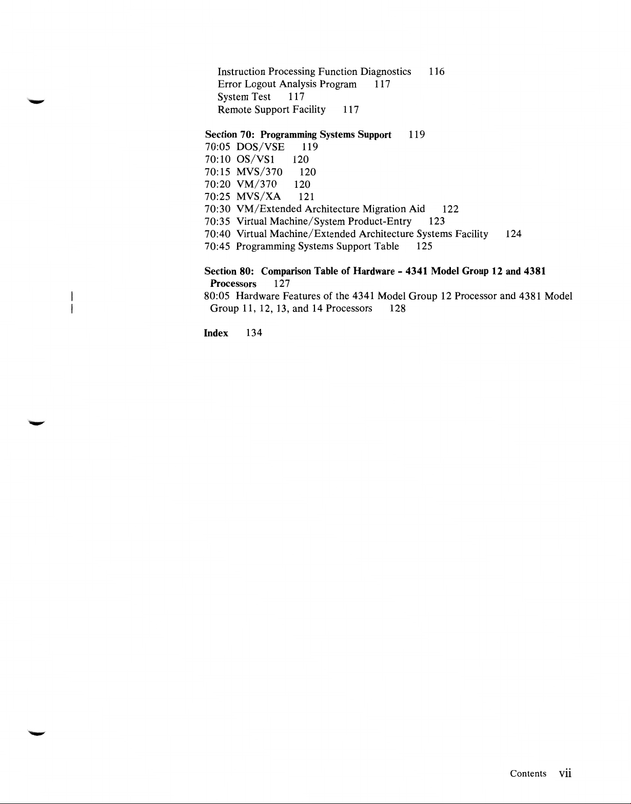
Instruction Processing Function Diagnostics 116
Error Logout Analysis Program
11
7
System Test 117
Remote Support Facility 117
Section 70: Programming Systems Support 119
70:05
70: 10
70:15
70:20
70:25
DOS/VSE
OS/VSl
MVS/370
VM/370
MVS/XA
119
120
120
120
121
70:30 VM/Extended Architecture Migration Aid 122
70:35 Virtual Machine/System Product-Entry 123
70:40 Virtual Machine/Extended Architecture Systems Facility 124
70:45 Programming Systems Support Table 125
Section 80: Comparison Table of Hardware - 4341 Model Group 12 and 4381
Processors 127
80:05 Hardware Features of the 4341 Model Group 12 Processor and 4381 Model
Group 11, 12, 13, and 14 Processors 128
Index 134
Contents vii
Page 9

Figures
1.
The 4381 Processor and console
2.
Two 64-mm MCMs
3.
A 64-mm MCM being hand held
4.
The 4381 MCM board without any modules mounted
5.
64-mm MCMs mounted on the MCM board
MCM board mounted within the 4381 Processor
6.
7.
64-mm MCM with a portion of the heat sink cut away 20
8.
An impingement cooling nozzle · 20
9.
Logical components in a 4381 Processor Model Group 11, 12, 13,
27
2
10.
General flow of data between the channels and processor storage 53
11.
Logical components in a 4381 Processor Model Group
12.
Data flow to and from processor storage
Model Group
13. The General Selection display 90
14. Dialup of a remote 4381 Processor via a 3275 display
15. Dialup of a remote 4381 Processor
display 92
16.
4381 Processor machine check code 103
17. 4381 Processor machine check interruptions
14
or 3
16
71
12
17
18
18
19
14
or 3 62
via
the high-speed buffers in a 4381
91
via
a host processor emulating a 3275
105
1,
or
viii
A Guide to the IBM 4381 Processor
Page 10
.
..._....
Section 01: Highlights
The 4381 Processor, available in four model groups,
is
general purpose processor that
It
30XX processors.
4300, and 30XX processors) and System/370 extended architecture (as in 308X
and 3090 processors).
Model Groups 11, 12, 13, and 14 of the 4381 Processor, which offer a wide range
of performance, are provided. Model Group 11, 12, and
are uniprocessors containing one instruction execution function. The Model Group
14 4381 Processor unit
functions each of which has its own channels. The Model Group
as
operates
operating system in which processor storage
Field upgrades of 4381 Processor model groups
Group
4381 Model Group 12 can be field upgraded to a 4381 Model Group 13, and a
4381 Model Group
support provides significant performance growth. The 4381 Model Group 14 has
an internal throughput rate of up to 4.9 times that of a 4381 Model Group
commercial processing and of up to 5.4 times that of a 4381 Model Group
scientific processing.
Model Groups
performance relative to Model Groups
withdrawn from marketing,
groups. However, optional features, including processor storage upgrades, can be
installed in 4381 Model Group
withdrawn model groups can be field upgraded to the current 4381 model groups
as follows: 4381 Model Group
Group 2 to a 4381 Model Group
Model Group
a tightly coupled multiprocessing configuration under the control of one
11
Processor can be field upgraded to a 4381 Model Group 12 Processor, a
14.
implements System/370 architecture (as in System/370,
is
a dual processor that contains two instruction execution
13
can be field upgraded to a 4381 Model Group 14. This
11through14
compatible with System/370, other 4300, and
is
of the 4381 Processor offer improved price
1,
2, and 3 of the 4381 Processor, which are
as
are model upgrades within these withdrawn model
1,
2,
and 3 Processors. In addition, these
1toa4381
13
Model Group 12 or 13, 4381 Model
or 14, and 4381 Model Group 3 to a 4381
is
an intermediate-scale,
13
4381 Processor units
14
shared.
is
supported. A 4381 Model
processor unit
11
for
11
for
The 4381 Processors offer higher internal performance and improved price
performance for intermediate system users relative to 4341 Processors. This
is
improved performance
technology for logic and processor storage. The logic packaging and cooling
designs implemented in 4381 Processors provide increased logic density without the
need for water cooling.
43
81
The
data processing capabilities offered by System/370, 4300, and 30XX processors,
as
well
extended architectures.
Processors support the range of commercial and engineering/ scientific
as
the advanced functions provided by System/370 and System/370
made possible by the use of large-scale integrated
Section
01
: Highlights 1
Page 11

The 4381 Processor Model Group
processors (such
Groups 12, 13, and
larger 4341 Processor model groups, System/370 Models 155 to 168, and 303X
processors.
Relative to 4341 Processors, 4381 Processors offer intermediate system users
increased internal performance and channel performance; improved price
performance; reliability, availability, and serviceability improvements; hardware
and programming systems compatibility; System/370 extended architecture
advantages; and a wide range of operating system support.
The 4381 Processors can be utilized in decentralized and distributed processing
environments that require higher internal performance and more channel capability
than
is
provided by 4341 Processors. They can also be used in 30XX installations
to support application offloading.
The 4381 Processors are particularly well suited to handle engineering/ scientific
applications, such as
of floating-point and binary multiply operations in 4381 Processors
improved. Standard engineering/ scientific assist features can be used to further
improve floating-point arithmetic performance for selected functions.
The 4381 Processors operate with a broad spectrum of IBM products that support
engineering/ scientific applications, including the 3251 Display Station and 5080
Graphics System, 3838 Array Processor, 7350 Image Processing System, Series/1
processors, and IBM personal computers. The 4381 Processors can also be used
with the IBM Device Attachment Control Unit and 7171 ASCII Device
Attachment Control Unit to implement engineering/scientific applications that
require the use of non-IBM devices. The IBM 4994 ASCII Device Control Unit
can be channel-attached to 4381 Processors. The 3044 Fiber Optic Channel
Extender Link can be used to extend the distance between terminals/ devices and
the 4381 Processor (up to two kilometers) while providing near local terminal
response time.
as
Models
14
of the
CAD/CAM,
11
is
a logical growth processor for System/370
135
to 148) and smaller 4341 Processors. Model
43
81
Processor provide a growth path for users of
graphics, and problem solving. The performance
is
significantly
System/370 extended architecture, which
processors,
MYS/Extended Architecture (MVS/XA) operating system. Therefore, a 4381
Processor can be used for
the entry
3090 processor and MVS/XA.
The 4381 Processors have extensive operating system support. When operating
with System/370 architecture
supported by the same operating systems
System/370 mode. When operating with System/370 extended architecture in
effect (in System/370 extended architecture mode), 4381 Processors are supported
by the same operating systems
System/370 extended architecture mode.
2 A Guide to the IBM 4381 Processor
is
implemented in 308X and 3090
is
also implemented in 4381 Processors, which are supported by the
MVS/XA
MVS/XA
processor in installations that expect growth to a 308X or
testing in a 308X or 3090 installation or
in
effect (in System/370 mode), 4381 Processors are
as
4341 Processors operating in
as
308X and 3090 processors operating in
as
Page 12
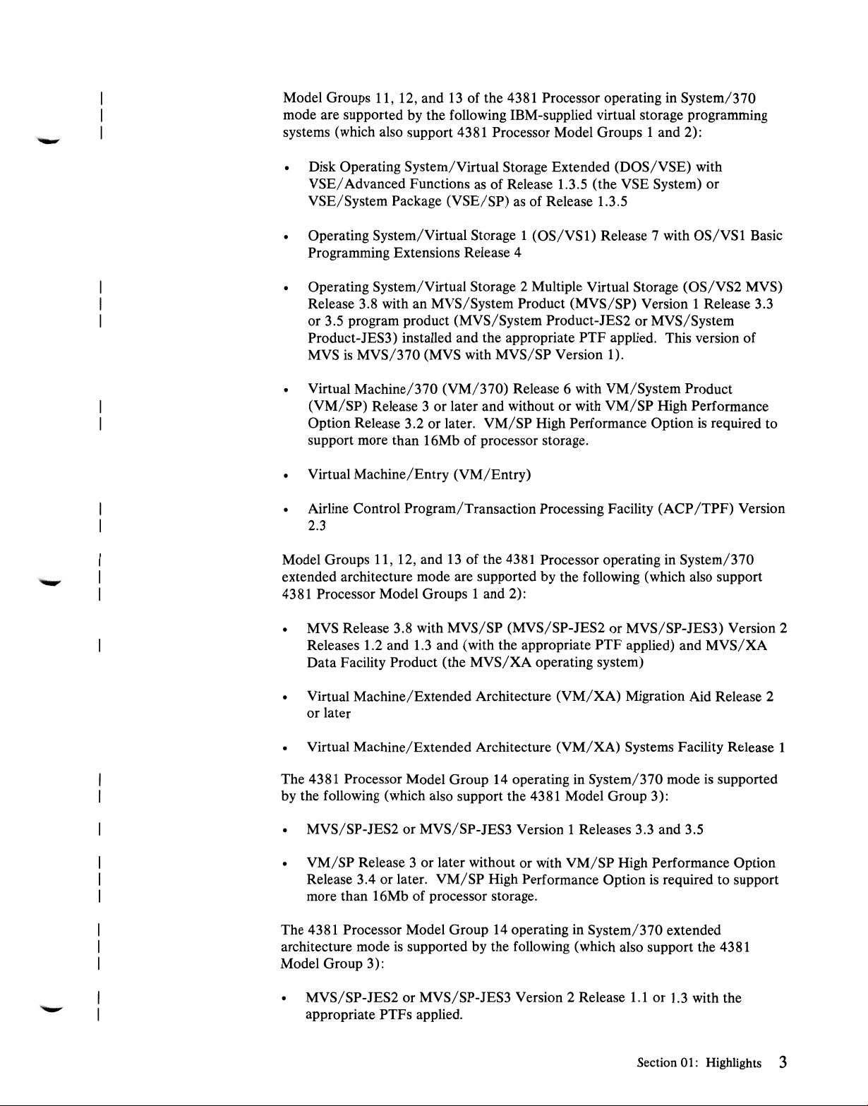
Model Groups 11, 12, and
13
of the 4381 Processor operating in System/370
mode are supported by the following IBM-supplied virtual storage programming
systems (which also support 4381 Processor Model Groups 1 and 2):
• Disk Operating System/Virtual Storage Extended (DOS/VSE) with
VSE/
Advanced Functions
VSE/System Package (VSE/SP)
as
of Release 1.3.5 (the VSE System) or
as
of Release 1.3.5
• Operating System/Virtual Storage 1
(OS/VSl)
Release 7 with
OS/VSl
Basic
Programming Extensions Release 4
• Operating System/Virtual Storage 2 Multiple Virtual Storage (OS/VS2 MYS)
Release 3.8 with an MYS/System Product (MYS/SP) Version 1 Release 3.3
or 3.5 program product (MYS/System Product-JES2 or MYS/System
Product-JES3) installed and the appropriate PTF applied. This version of
is
MYS
MVS/370
• Virtual Machine/370
(VM/SP) Release 3 or later and without or with
Option Release 3.2 or later.
(MYS with MYS/SP Version 1).
(VM/370)
Release 6 with VM/System Product
VM/SP
VM/SP
High Performance Option
High Performance
is
required to
support more than l 6Mb of processor storage.
• Virtual Machine/Entry (VM/Entry)
• Airline Control Program/Transaction Processing Facility
(ACP/TPF)
Version
2.3
13
Model Groups 11, 12, and
of the 4381 Processor operating in System/370
extended architecture mode are supported by the following (which also support
4381 Processor Model Groups 1 and 2):
• MYS Release 3.8 with MYS/SP (MVS/SP-JES2 or MVS/SP-JES3) Version 2
Releases 1.2 and 1.3 and (with the appropriate PTF applied) and
Data Facility Product (the
MVS/XA
operating system)
MVS/XA
• Virtual Machine/Extended Architecture
(VM/XA)
Migration Aid Release 2
or later
Virtual Machine/Extended Architecture
(VM/XA)
The 4381 Processor Model Group 14 operating in System/370 mode
Systems Facility Release 1
is
by the following (which also support the 4381 Model Group 3):
• MVS/SP-JES2 or MVS/SP-JES3 Version 1 Releases 3.3 and 3.5
VM/SP
•
Release 3.4 or later.
Release 3 or later without or with
VM/SP
High Performance Option
VM/SP
High Performance Option
is
required to support
more than 16Mb of processor storage.
The 4381 Processor Model Group 14 operating in System/370 extended
is
architecture mode
supported by the following (which also support the 4381
Model Group 3):
1.1
or
1.3
• MVS/SP-JES2 or MVS/SP-JES3 Version 2 Release
with the
appropriate PTFs applied.
Section
01
: Highlights 3
supported
Page 13
•
•
VM/XA
VM/XA
Migration Aid Release 2 or later
Systems Facility Release 1
The hardware facilities of, and
effectively be used by the MVS/370, MVS/XA, and
To aid in the transition from
Processor, two migration aids are provided (see discussion in Section 70:05). Less
effort
is
required to convert from
MVS/370
operating systems.
Highlights of 4381 Processor Model Groups 11, 12, 13, and 14 are as follows:
• Upward compatibility with 4300 System/370 mode, System/370, and 30XX
operate in 4341 Processors under a
implemented in 4341 Processors
The System/370 extended architecture mode of operation, not provided in
4341 Processors,
compatibility for most 4300, 30XX, and System/370 problem programs and
most
extended architecture support, such as MVS/XA.
because of the basic compatibility between the
architecture and programming systems has been maintained in 4381 Processors
through implementation of the System/370 mode of processor operation. This
mode provides compatibility for 4300 System/370 mode, System/370, and
30XX control programs and problem programs. Problem programs that
can also operate in a 4381 Processor under a
supervisor if they are not processor- or time-dependent. The ECPS:VSE mode
is
also implemented in 4381 Processors. This mode provides
MVS/370
subsystems but requires a control program with System/370
1/0
devices for, 4381 Processors can most
VM/370
DOS/VSE
to
MVS/370
OS/VSl
to
MVS/370
DOS/VSE
is
not implemented in 4381 Processors.
with installation of a 4381
than from
OS/VSl
ECPS:VSE mode supervisor
DOS/VSE
operating systems.
DOS/VSE
and
OS/VS2
System/370 mode
to
• The following are instruction processing function features of 4381 Processors.
is
Instruction processing function logic
technology. Logic chips (704-circuit) with faster circuit speeds than the
704-circuit chip used in most 4300 Processors are used in 4381 Processors.
However, the logic packaging and cooling technique implemented
Processors significantly increase the logic circuit density on a logic board
without the need for water cooling. (See Section 10:05 for a detailed logic
technology discussion.)
Implementation of a System/370 mode and a System/370 extended
architecture (System/370-XA) mode
architecture implemented for System/370 mode operations includes nearly all
the extensions implemented in large-scale processors, such as the 308X and
3090.
System/370 extended architecture
changes and additions. The major new functions provided by this architecture
are 31-bit addressing and dynamic channel subsystem architecture. The 31-bit
addressing capability enables two gigabytes (over 2 billion bytes) of virtual
storage and real storage to be addressed, versus a maximum of over 16 million
bytes for the 24-bit addressing supported by System/370 architecture. A
bimodal operation
addressing and programs that use 31-bit addressing to operate concurrently
when System/370-XA mode
is
supported that permits programs that use 24-bit
is
in effect.
implemented in large-scale integrated
in 4381
is
standard. The System/370
is
System/370 architecture with certain
4 A Guide to the IBM 4381 Processor
Page 14

The dynamic channel subsystem architecture eliminates channel addressing,
all
1/0
supports queuing of
requested
interruption mechanism and extended
1/0
operations in hardware, and supports an expanded
requests, provides channel path selection for
1/0
device addressing.
1/0
all
The mode in which the 43
operator at initial microcode load (IML) time. The mode selected remains in
effect until another IML
System/370-XA mode microcode to be used for this IML.
The cycle time of 4381 Model Group
For 4381 Model Groups
The instruction processing function design provides increased instruction
execution performance. Instruction prefetching
the overlap of instruction fetching with instruction execution during sequential
instruction processing. In addition, an eight-byte-wide arithmetic logic unit
used that enhances the performance of decimal and floating-point operations.
Improvements in the number of functions performed during the instruction
cycle of 4381 instruction execution (like those in 4341 Processors) result in the
faster execution of many other instructions, most of which are among the more
frequently used instructions.
The standard instruction set for 4381 System/370 mode of operation provides
decimal, binary, and floating-point arithmetic operations (including the
extended floating-point format that provides the equivalent of up to 34 decimal
digits).
instruction set defined for System/370 except for direct control and RESUME
1/0
Section
are also standard.
For
4381 Model Groups 11, 12, and 13, it consists of the entire
instructions and those associated with multiprocessing (as discussed in
10: 10). For the 4381 Model Group 14, multiprocessing instructions
81
Processor
is
performed and causes the System/370 mode or
13
and 14, cycle time
is
to operate
11
and 12 Processors
is
56 nanoseconds.
is
implemented that results in
is
determined by the
is
68
nanoseconds.
is
The standard instruction set for 4381 System/370-XA mode of operation
includes all the instructions defined for System/370 extended architecture. All
the semiprivileged and all the nonprivileged instructions in System/370
architecture are also defined for System/370 extended architecture but
differences exist in the set of privileged instructions supported by the two
architectures (see Section 10:
Three engineering/scientific assists are provided for 4381 Processors. The
Multiply and Add Facility
It
is
14.
computations, such as matrix inversion, decomposition, and multiplication.
These computations are used, for example, in finite element analysis, linear
programming, and statistical analysis. This feature supports only long-format
(64-bit) floating-point numbers and can provide a reduction in instruction
processing function busy time of up to
by the MULTIPLY AND ADD instruction (see Section 20:05).
The Square Root Facility
to improve the performance of square root operations involving long- or
short-precision floating-point arithmetic.
designed to improve the performance of certain mathematical
10).
is
standard in 4381 Model Groups 11, 12, 13, and
35
percent for the instructions replaced
is
standard in 4381 Model Groups 11, 12, 13, and 14
Section
01:
Highlights 5
Page 15

The Mathematical Function Facility (not implemented in 4341 Processors)
standard in 4381 Model Group 12, 13, and
of eight register-to-register floating-point instructions that perform elementary
mathematical functions. The supported functions are exponentiation and
natural and common logarithms. The instructions support short and long
precision for the two operands involved (see Section 20:05). This facility
reduces processor busy time by up to
permits selected scientific subroutines to be executed faster than with
conventional programming (FORTRAN subroutines).
Timing and debugging features like those in System/370, 30XX, and other
4300 Processors (3.3-ms-resolution interval timer, time-of-day clock, CPU
timer, clock comparator, monitoring feature, and program event recording) are
standard in 4381 Processors. The time-of-day clock and CPU timer have a
one-microsecond resolution.
The standard byte-oriented operands facility permits byte boundary alignment
for the operands of nonprivileged instructions, making it unnecessary to add
padding bytes within records or to blocked records to align fixed- or
floating-point data. In 4381 Processors, minimal performance degradation
results from the use of unaligned data.
Functions of the System/370 Extended Facility/Feature for 30XX Processors
are standard in 4381 Processors. These facilities are low address protection (to
protect the contents of locations 0 to 511 from accidental modification), the
TEST PROTECTION and INVALIDATE PAGE TABLE ENTRY
instructions (for control program use), the common segment facility (to
improve address translation performance for
environments), MYS-dependent instructions (ECPS:MVS feature in 4381
Processors), and Virtual Machine Extended Facility Assist.
14
Processors and provides a group
65
percent for the assisted functions.
MYS
and
VM/370
is
It
The facilities provided by the 3033 Extension feature for 30XX Processors are
standard in 4381 Processors. The Dual Address Space Facility for both modes
(which improves the performance of MYS/SP Cross Memory Services),
1/0
START
(which
MYS assists (included in the 4381 ECPS:MVS feature) are implemented in
4381 Processors. The suspend and resume facility provided by the 3033
Extension feature
but a comparable function
System/370-XA mode.
Dynamic address translation and channel indirect data addressing features to
support a virtual storage
For System/370 mode (which uses 24-bit addressing), one virtual storage of
16,777,216 bytes (16Mb) maximum or multiple virtual storages up to
16M-bytes each can be supported. For System/370-XA mode (which uses
31-bit addressing), one virtual storage of up to 2,147,483,648 bytes (2
gigabytes) or multiple virtual storages of up to 2 gigabytes each can be
supported.
A segment protection facility (not provided for 4341 Processors) that provides
the ability to prevent stores to protected virtual storage segments
for System/370 mode. For System/370-XA mode, a page protection facility
FAST RELEASE instruction queuing for System/370 mode only
is
basic to the System/370-XA mode channel subsystem), and two
is
not implemented for 4381 System/370 mode of operation
is
basic to the channel subsystem defined for
and/
or virtual machine environment are standard.
is
standard
is
6 A Guide to the IBM 4381 Processor
Page 16

provided instead of the segment protection facility. Page protection can be
used to prevent any writing in protected 4K pages of virtual storage.
A
VM/370
hardware assist function (ECPS:VM/370) and an MVS hardware
assist facility (ECPS:MVS) are standard in 4381 Processors. ECPS:VM/370
and ECPS:MVS can be used concurrently to improve performance when
MVS/SP Version 1 executes in a virtual machine under the control of
VM/370
with the VM/System Product.
ECPS:VM/370 consists of the Virtual Machine Assist, Control Program
Assist, Expanded Virtual Machine Assist, Virtual Interval Timer Assist, and
It
Shadow-Table Bypass Assist components.
System/370 mode
ECPS:MVS consists of
is
in effect.
13
privileged instructions and the page fault assist
function, all of which are operative during System/370 mode operations.
of the
13
instructions are operative for System/370-XA mode operations. The
can be used only when
Six
standard Virtual Machine Extended Facility Assist enables the ECPS:MVS
instructions to be executed directly by an MVS virtual machine to improve
performance.
is
Preferred Machine Assist (not provided for 4341 Processors)
standard in
4381 Processors and can be used only during System/370 mode operations.
is
designed to improve the performance of MVS/SP Version 1 running in a
preferred virtual machine.
It
is
Instruction retry
standard to attempt to correct errors that occur during
instruction execution without programming assistance. For certain hardware
facilities (reloadable control storage, channel buffers, and the high-speed
buffer and its swap buffer), the instruction retry facility provides automatic
hardware reconfiguration to assign spare storage when a retry does not correct
an error. The reconfiguration facility permits continued system operation,
is
without performance degradation in some cases. Maintenance
is
when reconfiguration
no longer possible.
performed
The following are significant storage features of 4381 Processors.
All storage in a 4381 Processor-processor, control, high-speed buffer, and
local-is
implemented using monolithic technology. The technology used for
processor storage in 4381 Processors provides much denser storage chips (64K
as
bits per chip
above 16Mb) than
in 4341 Processors and a 256K-bit chip for processor storage
is
used in System/370, 303X, or 308X processors (2K, 4K,
or 16K bits per chip).
is
A two-level storage system
as
storage used
backing storage for a smaller high-speed buffer storage. The
implemented, consisting of large processor
instruction processing function works mostly with the high-speed buffer so that
is
the effective processor storage cycle
a fraction of the actual processor
storage cycle.
4K bytes for a 4381 Model Group 11, 32K bytes for a 4381 Model Group 12,
13
and 64K bytes for a Model Group
K=
1024) are standard. The full buffer size
is
effect
4K bytes. When page size
12, only half of the high-speed buffer
of high-speed buffer storage (where
is
used when the page size in
is
2K bytes in a 4381 Model Group
is
used. A doubleword of data
11
is
fetched
or
Section
01
: Highlights 7
Page 17

from the buffer in 68 nanoseconds and stored in the buffer in 102 nanoseconds
for 4381 Model Groups
11
and 12.
For
a 4381 Model Group 13,
56
or
84
nanoseconds are required for a fetch or store, respectively.
For
the 4381 Model Group 14, each of the two instruction processing
functions has its own dedicated 64K-byte high-speed buffer as a standard
feature. These two high-speed buffers operate using 4K-byte pages only.
Facilities for the required high-speed buff
er
communication in a
multiprocessing environment are implemented in the Model Group 14,
er
data
including buffer-to-buff
transfer.
4Mb, 8Mb, and 16Mb of processor storage are available for the 4381 Model
Group
(where
M=l,048,576).
For
4381 Model Group 12 and 13
11
Processors, 8Mb, 16Mb, 24Mb, and 32Mb are available. A Model Group 14
or
can have 16Mb, 24Mb,
32Mb of processor storage. Store and fetch
protection and reference and change recording are standard. Store and fetch
protection are provided
processors with up to 16Mb installed.
16Mb installed, store and fetch protection are provided
of
A portion
not
will
highest addressed installed processor storage in a 4381 Processor
be accessible to programs, as in 4341 Processors. The amount of
on
a 2Kb basis (one key for each 2Kb) for 4381
For
4381 processors with more
on
a 4Kb basis.
than
unavailable processor storage for 4381 Processors (called auxiliary storage) is a
of
minimum
64Kb (104Kb for the Model Group 14) for
operation for the minimum number
System/370-XA
mode, a minimum of l 12Kb (220Kb for the Model Group
of
UCWs (128) defined.
System/370
For
mode
of
14) of auxiliary storage is required for zero subchannels and 128 control units
defined.
Reloadable control storage
instruction processing function
writable, instead
of
read-only, control storage offers the advantages of
contain all the microcode required
of
4381 Processors is standard. Use
by
the
of
to
improved system serviceability and ease of optional feature and engineering
change installation.
The TEST BLOCK instruction (not implemented in
to
provided to enable the control program
processor storage
unusable because
and/
or
their associated one
of
uncorrectable errors. Known unusable blocks and keys
determine which 4Kb blocks of
4341 Processors) is
or
two storage protect keys are
are saved across power-offs. This instruction can also be used for processor
storage validation.
The TEST BLOCK instruction enables the operating system
of
4Kb blocks from its list
assignable page frames and prevents abnormal
program terminations that could result from the uncorrectable storage errors.
Error checking and correction
(ECC)
hardware
is
standard.
corrects all single-bit processor storage errors, and detects
all double-bit and most multiple-bit errors. Correction
consist
4341 Processors)
of
one solid and one intermittent error (which
is
also provided via microcode (see discussion in Section
to
delete unusable
<
It
automatically
but
does
not
of
double-bit errors that
is
not
implemented in
correct
60:10).
8 A Guide to the IBM 4381 Processor
Page 18

The following channel features are provided for 4381 Processors.
Two channel groups are available for Model Groups 11, 12, and 13. The
standard channel group consists of one byte multiplexer and five block
5.
multiplexer channels addressed 0 through
consists of six block multiplexer channels addressed 6 through
The optional channel group
B.
Block
multiplexer channel 5 in the standard channel group can be configured as a
as
byte multiplexer instead of
For
the 4381 Model Group 14, one channel group consisting of one byte
multiplexer channel (0) and five block multiplexer channels
a block multiplexer channel.
(1
through 5)
is
standard for each of the two instruction processing functions. The fifth block
as
multiplexer channel in each channel group can be configured
a byte
multiplexer channel. Optionally, one additional channel group, which provides
three additional block multiplexer channels for each channel group (a total of
six additional channels) can be installed.
is
Functionally, a byte multiplexer channel for a 4381 Processor
equivalent to
that for System/370, 30XX, and other 4300 processors. The standard
(channel 0) and optional (channel 5) byte multiplexer channels in Model
Groups 11, 12, and
each have a
24Kb/sec
maximum data rate (28Kb/sec
13
for the Model Group 14) for one-byte transfer operations for byte mode
mod.e
1/0
operations. Unbuffered.burst
devices cannot be attached to the
byte multiplexer channels in a 4381 Processor.
is
Functionally, a block multiplexer channel in a 4381 Processor
equivalent to
that for System/370, 30XX, and 4300 processors. A block multiplexer
channel in 4381 Processors can also operate in selector channel mode.
is
The data streaming mode of channel operation that
is
30XX Processors
standard for all the block multiplexer channels in a 4381
provided for 4341 and
Processor. Data streaming mode enables certain 4381 channels to handle
faster data rates (up to 3Mb/sec) over a longer channel-to-control unit cable
length for attached control units that are also capable of operating in data
streaming mode (see discussion in Section 20:20). Both data streaming and
nonstreaming devices can be attached to the block multiplexer channels in a
4381 Processor.
For
the standard channel group in a 4381 Model Group 11, 12, or 13, the
is
maximum aggregate data rate
a Model Group 11, the maximum aggregate data rate
22Mb/sec
maximum aggregate for eleven block multiplexer channels.
14 Mb/sec. For the optional channel group in
is
8Mb/sec, providing a
For
a
Model Group 12, the optional channel group has a maximum aggregate data
rate of lOMb/sec, providing a 24Mb/sec maximum aggregate for the eleven
block multiplexer channels. The maximum aggregate data rate for the optional
channel group in a Model Group
16Mb/sec, with a
30Mb/sec
maximum
13
is
aggregate data rate for eleven block multiplexer channels.
For
the Model Group 14, a maximum aggregate data rate of
ten block multiplexer channels (15Mb/sec for each channel group)
The maximum aggregate data rate for 16 block multiplexer channels
36Mb/sec
(18Mb/sec
for each eight-channel group).
30Mb/sec
is
possible.
is
for the
Channels with data rates of up to 3
Mb/sec
and the block multiplexing
capability support attachment to the 4381 Processor of 3380, 3375, 3370,
Section 01: Highlights 9
Page 19

3330-series,
have rotational position sensing capability and can be used only with block
multiplexer channels.
Optionally, one Channel-to-Channel Adapter can be installed in a 4381
Processor (any model group) and attached to any block multiplexer channel.
The adapter can be used to connect a channel in a 4381 Processor to a channel
in a System/360, System/370, 30XX, 4321, 4331, 4341, 4361, or another
4381 Processor. Alternatively, the 3088 Multisystem Channel Communication
Unit can be used to interconnect the 4381 Processor with certain other
processors via channels.
3340/3344,
and 3350 direct access storage. These disk devices
The fast release function of the START
instruction (implemented only in Model Group 12 4341 Processors) and
queuing of SIOF instructions (not implemented in 4341 Processors) are
standard features in 4381 Processors. These functions are designed to reduce
I/
0 processing time.
A 3205 Color Display Console, or a 3278 Model 2A Display Console or 3279
Model 2C Color Display Console equipped with an operator console keyboard
and operator control panel feature
4381 Processor. Display mode and (for System/370 mode only) a
printer-keyboard mode are standard. The display console natively attaches to
4381 Processors. The display console
operator-to-operating system communication, and by the customer engineer to
perform diagnostic functions.
Up to three displays
Processor in addition to the required 3205, 3278 Model 2A, or 3279 Model 2C
console. The additional three units can be 3205 Color Display Consoles, 3278
Model 2A Display Consoles, 3279 Color Display Consoles Model 2C, 3268
Model 2 Printers, 3268 Model 2C Color Printers,
1,
2, 1 C,
and/
cannot be installed together with 3278 Model 2A or 3279 Model 2C displays.
The additional displays can be used
The 3287 or 3268 Printer can be used for hard-copy backup of an operator
console that operates in display mode. Models
3268 Model 2C provide color printing. A printer
hard-copy output when the display console operates in printer-keyboard mode.
and/
or printers can be natively attached to a 4381
or 2C in any combination with the restriction that 3205 displays
1/0
FAST RELEASE (SIOF)
is
required as the operator console for a
is
used for manual operations,
as
alternate
and/or
and/
lC
is
3287 Printers Models
or additional consoles.
and 2C of the 3287 and the
recommended for
10 A Guide to
the
IBM 4381 Processor
The Remote Operator Console Facility (ROCF), a no-charge specify option
that requires the Remote Support Facility, gives an operator at a host location
the ability to dial up and control a powered-on remote 4381 Processor using a
3275 Display Terminal or an emulated 3275 attached to a host processor.
Host processor program support for ROCF
MVS/XA, and
discussion in Section 40:15).
1/0
devices that attach to 4341 Processors and that are available from IBM
will also attach to 4381 Processors.
The Device Attachment Control Unit (DACU) can be attached to a block
multiplexer channel in 4381 Processors. The DACU provides two commonly
used industry interfaces for the attachment of non-IBM
VM/370
with the appropriate program products installed (see
is
provided by MVS/370,
1/0
devices: UNIBUS
Page 20

(a registered trademark of the Digital Equipment Corporation), which provides
a parallel direct memory access (DMA) interface, and EIA RS-232C, which
an industry standard serial communication interface. The DACU permits
attachment of a wide variety of non-IBM
sensors, graphic devices, laboratory instruments, and minicomputers. This
control unit makes a 4381 Processor suitable for a variety of engineering and
scientific applications.
• The large-scale integrated technology implemented in 4381 Processors for
most logic and all processor storage provides higher internal performance,
increased reliability, and compact processor unit design. The module-on-board
logic packaging eliminates one entire level of packaging (logic cards), and the
impingement cooling technique assures adequate cooling of the high-density
logic modules using only room-temperature air
technology discussion in Section 10:05.)
• The power system hardware in 4381 Processors
power hardware used in most 4341 Processors. The 4381 power hardware
increases reliability, reduces space requirements, and aids serviceability.
Improvements in the fault-locating ability and the usability of power
diagnostics have also been made.
• Extensive hardware and programming systems error recovery and repair
features for 4381 Processor hardware errors are provided to improve system
availability and serviceability. These features include enhanced facilities
implemented in other 4300 Processors, such
data after a hardware error occurs to generate a reference code that identifies
the field-replaceable unit or the procedure to follow to attempt to locate the
malfunction. Additional recovery facilities (such as double-bit error correction
and hardware reconfiguration) are implemented.
1/0 devices, such
as
the cooling medium. (See
is
totally different from the
as
automatic diagnosis of logout
as
plotters,
is
is
The Problem Analysis facility
designed to be used by the operator to aid in problem determination and can
result in faster fault isolation and reduced system downtime.
usability and functional improvements over the Problem Analysis facility
provided for 4341 Processors (see discussion in Section 60: 15).
Inquiry into a remote data bank by the on-site customer engineer and remote
diagnosis of hardware failures by IBM support center personnel are supported
via the recommended, no-charge Remote Support Facility (RSF), which
functionally like RSF for 4341 Processors.
The physical components of a 4381 Processor configuration are a 4381
Processor, an operator console (a 3205 Color Display Console, 3278 Model
2A Display Console, or 3279 Model 2C Color Display Console), and
devices. The 4381 Processor, which
page 12.
The 4381 Processor unit contains two diskette drives (instead of one
4341 Processor). These drives (shown in Figure 1 on page 12 are easily
accessible to the operator and space
store diskettes not in use. The second diskette drive
System/370 extended architecture functions and operations and enables more
as
diagnostics (such
Problem Analysis) to be online for ease of use. Two
provided for 4381 Processors. This facility
It
provides
is
air-cooled,
is
provided to the left of the two drives to
is
shown in Figure 1 on
is
required to support
1/0
as
is
is
in a
Section
01
: Highlights
11
Page 21

different operational diskettes (called functional diskette 1 and functional
diskette 2) are provided for the two diskette drives.
Figure 1. The 4381 Processor and console
While the logical designs of the functional components of a 43
very similar to
physical components in a 4381
The
logic package, the cooling components,
support processor, the diskette drives, and the
hardware are different in 4381
improve speed
The
upright design
the
4381 Processor unit is the same size for all 4381 model groups
3
and
11through14).
a raised floor and thus
The
4381 Model
provides twice the internal performance
occupies
the heat,
Model
Group 1 but
dissipates
Group
69%
and
weighs
Group
occupies
99%
1.
These comparisons assume a 4341 without a Channel-to-Channel
the
designs in a 4341 Processor, the physical design
and
4341 Processor are different.
power
and
4341 Processors. These differences
and
reliability, reduce cost,
of
the 4381 Processor also reduces space requirements
Any
4381 model group can
can
be
placed in end-user work areas.
Group
of
11
provides twice the internal performance
of the heat, and weighs
12 has
about
the floor space, uses
84%
as much as a 4341 Model
69%
of the floor space, uses
and/
twice the number of logic circuits
of
the 4341 Model
89%
of the power, dissipates
95%
hardware components, the
Channel-to-Channel
or reduce space requirements.
be
installed with
Group
107%
as much as the 4341 Model
81
Processor are
and
Adapter
(1
or
Group 2 but
83%
2.
The
4381
of
the
4341 Model
of the power,
most
and
through
without
and
of
12 A Guide to the IBM
4381
Processor
Page 22

Adapter, which requires an additional frame in a 4341 Processor but not in a
4381 Processor.
In summary, 4381 Processors offer intermediate system users:
• Improved internal performance, price performance, and channel performance
relative to 4341 Processors
• Improved engineering/ scientific performance relative to 4341 Processors
• Implementation of nearly all System/370 architecture facilities and all the new
facilities of System/370 extended architecture
• Compatibility with other 4300, 30XX, and System/370 processors
• A full range of operating system support for both System/370 and
System/370-XA modes
• Improved reliability and availability characteristics and the expanded
serviceability functions implemented in 4341 Processors
• Evolutionary logic technology packaging that provides greater logic chip
densities with air cooling
• Reduced floor space requirements relative to 4341 Processors
• Four field upgradeable models that provide a wide range of performance and
nondisruptive growth
Section
01
: Highlights
13
Page 23

Section 10: Technology
10:05 Technology
Introduction
The price performance and compact size of the 4381 Processor unit have been
achieved in part through the use of large-scale integrated bipolar semiconductor
technology for logic chips and large-scale integrated packaging of logic chips. In
addition, a 64K-bit and 256K-bit dynamic storage chip are used for processor
storage.
Large-scale integrated technology and packaging are utilized to increase logic
circuit density. The major benefits of increased circuit density are faster logic
speed and higher logic reliability. In addition, logic cost and space requirements are
reduced.
The speed of logic circuitry
shorter the distance, the less the time it takes for the signals to travel from one
circuit to another, and
power reduces the total amount of heat generated by the circuitry, which reduces
the total amount of cooling required. However, the higher density of circuits
concentrates the heat that
and
Architecture
is
affected by the distance signals have to travel. The
at
the same time less power
is
generated in a smaller area.
is
consumed. The use of less
14 A
Guide
to the
IBM
is
The reliability of logic circuitry
interconnections and (2) level of packaging (location and wire length) at which the
interconnections occur (which determines the number of times an electrical current
must flow between dissimilar materials). External connections (the wiring among
circuits) are the least reliable part of logic circuitry. Thus, circuit connections made
on a chip are more reliable than those made off a chip. Reductions in the number
and length of external connections (those made off the chip via a card or board, for
example) improve reliability.
The large-scale integrated (LSI) technology in which the logic in the 43
Processor
4341 Processors but provides faster circuit speeds. The packaging of 4381 logic
chips on a ceramic substrate
Processors and
fewer chips are placed on a substrate for the 4381 Processor than for the 308X
Processor Unit to reduce cooling requirements. The packaging of a logic module
4381
Processor
is
implemented
is
similar to the packaging used for 308X logic modules; however,
is
related to the ( 1) number of circuit
81
very similar to the LSI technology implemented in
is
an extension of the packaging used in 4341
Page 24

and the cooling process used in 4381 Processors had not been implemented in IBM
processors before the 4381.
is
The multilayer logic board design first used in the 3081 Processor Unit
in the 43
for the 4381 Processor eliminate
and increase logic speed relative to the 4341 implementation. Logic in the 4381
utilizes advanced features that were first used to package logic chips in other 4300
Processors but extends these features to significantly increase the circuit density of
a substrate.
Logic wiring in IBM processors other than the 4381, 308X, and 3090 occurs at
several levels. First, elementary components (transistors, diodes, and resistors) on
a chip are connected to form circuits, which are then interconnected at the chip
level. Additional circuit connections are then made at the logic module level (that
is,
(card-on-board packaging) and circuit connections among the cards on the same
board and among cards on different boards are made via cabling. This design
used in 4300 Processors other than 4381 Processors.
81
Processor. The logic module packaging and logic module board design
an
entire level of packaging, aid logic reliability,
within the substrate) and at the card level. Cards are mounted
on
also used
boards
is
Logic
Chip,
Module,
Card-on-board packaging
unit. Instead, logic modules are mounted directly on a multilayered board, which
provides the ability to interconnect the logic modules
wiring, thus eliminating most intraboard cabling.
and
Board
The logic chip used in the 4381 Processor unit
(approximately
components (resistors, diodes, and transistors). The 7000 elementary compone,1ts
on
The logic chip for the
(704) as the chip used in other 4300 Processors. However, a slightly different
technology than
4381 chip. This technology reduces the size of the transistors
more power
1.15 nanoseconds for 4381 Model Groups 11, 12,
one-half that of the 4341 Model Group 2 logic chip) and a chip circuit speed of
nanoseconds for 4381 Model Groups
Of the 704 circuits available
in the logic implemented in the
per chip
interconnections on the chip itself. A logic chip in the
several feet of wire that interconnects the elementary components and circuits
the chip.
Design
3/16
a chip can be connected to form a maximum of 704 logic circuits.
is
used for the 704-circuit chip in 4341 Processors
is
used. These differences result in a 4381 chip circuit speed that
is
made possible in part because three layers of wiring are used for
is
not used for most of the logic in the 4381 Processor
on
the board via imbedded
is
4.57 by 4.57 millimeters
of an inch square) and contains over 7000 elementary
43
81
Processor has the same maximum logic circuit capacity
is
used for the
on
a 4381 chip and
1,
2, and 3 (approximately
13
and 14.
on
a single chip, the average number actually utilized
43
81
Processor
is
650. The high circuit utilization
43
81
Processor can contain
is
.7
on
The
43
81
logic chips are mounted on a multilayer ceramic substrate that
millimeters (about 2.5 inches) square and 5.5 millimeters (.2 of an inch) thick,
which
is
larger than the ceramic substrate for 4341 Processor logic
by 50 millimeters or approximately 2 inches square) but smaller than the ceramic
substrate for the 3081 logic module (90 millimeters, about 3.5 inches, square).
Section 10: Technology and Architecture
is
(SO
millimeters
64
15
Page 25

The 64-millimeter (mm) ceramic substrate for the 4381 has 36 chip positions,
which compares to 9 positions maximum per 4341 ceramic substrate.
On
average,
30 logic chips are mounted on a ceramic substrate in a 4381 Processor. The
64-mm substrate, which
is
called a multichip module (MCM),
is
shown in Figure
Logic and array chips can be intermixed on the ceramic substrate used in the 4381
logic module. The mixing of logic and array chips on a substrate was first done in
4331 and 4341 Processors. This approach permits arrays to be located closer to
the logic that utilizes them and, therefore, increases logic speed.
""1llJlf
2.
Figure 2. Two
16
A Guide to the IBM 4381 Processor
64-mm
MCMs
The 4381 ceramic substrate contains from 20 to 32 layers for interconnecting the
mounted chips. The ceramic substrate has 882 pins brazed to the bottom of it to
input/
provide
output and power capabilities. This compares with 361 pins in the
SO-millimeter logic module in a 4341 Processor.
The MCM
(including the attached heat sink used for cooling as described later)
is
the basic field-replaceable unit (FRU) for 4381 logic. The module
is
35
millimeters (about 1.4 inches) high and weighs 250 grams (a little over one-half a
pound). An MCM can be quickly and easily removed from the MCM board and
replaced with another MCM. Figure 3 on page
17
shows an MCM being hand
held.
The advances implemented in the ceramic substrate for 4381 logic can be seen by
23
layers
comparing it with the substrate for 4341 Processors. A maximum of
present in the 50-mm ceramic substrate used in 4341 Processor logic.
On
is
average,
six chips are contained in the 50-mm module.
The MCMs for the 4381 Processor are mounted directly on a multilayer board
similar to that used in 308X processors. The MCM board for a 4381 Processor
is
Page 26
700 by 600 millimeters (27.6 by 23.6 inches) in size and 4.6 millimeters (about
1/4
of an inch) thick (the same size as the TCM board in a 308X Processor Unit).
is
The MCM board has 22 module positions and
Figure 5 on page
18
shows how MCMs are mounted on the MCM board.
shown in Figure 4 on page 18.
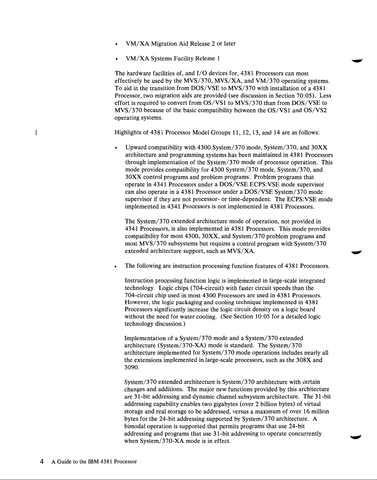
Figure 3. A 64-mm
The instruction processing logic for 4381 Processor Model Groups 11, 12, and
(exclusive of that for the support processor subsystem and some channel functions)
is
contained in 22 MCMs and these modules are mounted on one MCM board.
The 4381 Processor Model Group 14 contains two MCM boards. The fully loaded
MCM
board weighs 37 kilograms (81.4 pounds). The MCM board has 8 layers for
interconnecting the circuits on the MCMs and contains 1435 meters (about 4707
feet) of wiring for circuit interconnections. Figure 6 on page 19 shows the MCM
board as it
Since all instruction processing logic
Model Group 11, 12, or 13, interboard cabling for logic
increases logic speed and reliability. In the 4341 Processor, two boards are
required for logic and 400 cables are used for circuit connections between the two
boards. For a 4381 Model Group 14, some cabling between the two MCM boards
is
required for communication between the two instruction processing functions.
The standard card-on-board approach (a 22-card board)
functional components of the 4381 Processor. There
board, one board to support certain channel functions, and two boards for support
processor components.
MCM
being hand held
is
mounted on its side within the frame of a 4381 Processor.
is
contained on one board in a 4381 Processor
is
eliminated, which
is
used for other
is
one processor storage
13
Section 10: Technology and Architecture 1 7
Page 27

Figure 4. The 4381
MCM
board without any modules mounted
Figure 5. 64-mm MCMs mounted on the MCM board
18
A Guide to the IBM 4381 Processor
Page 28
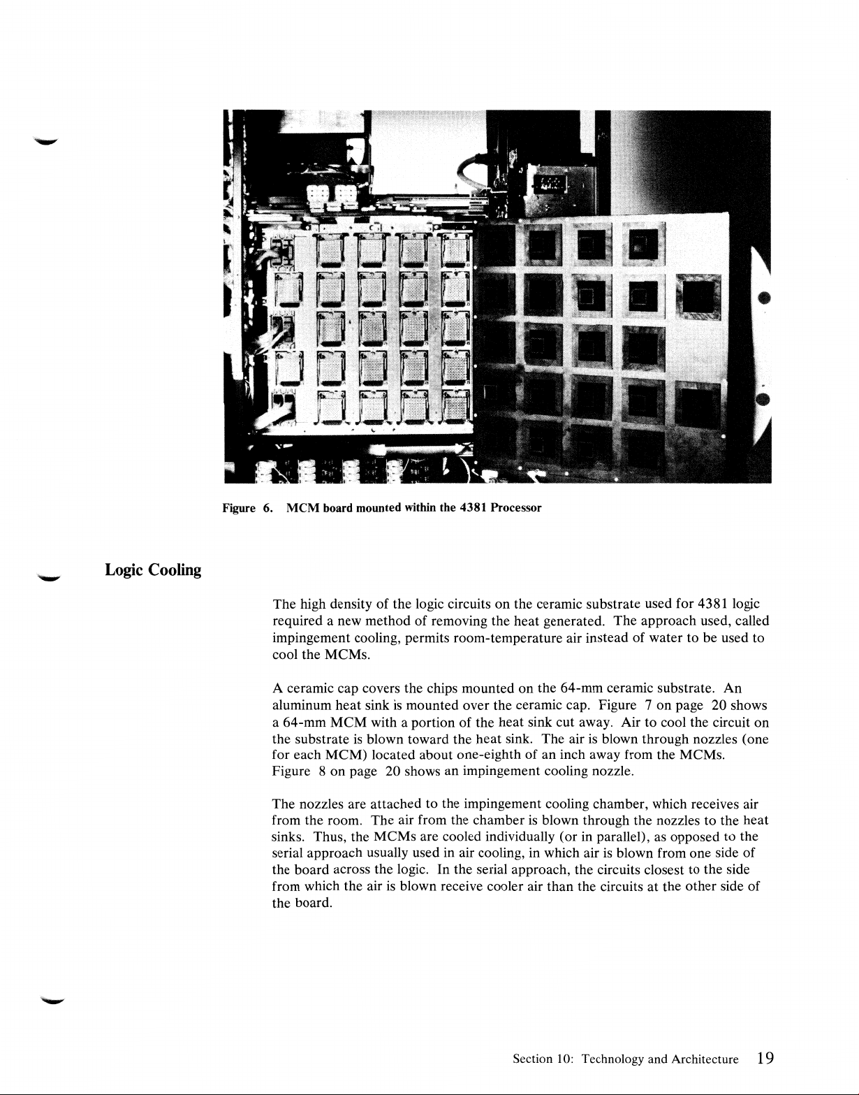
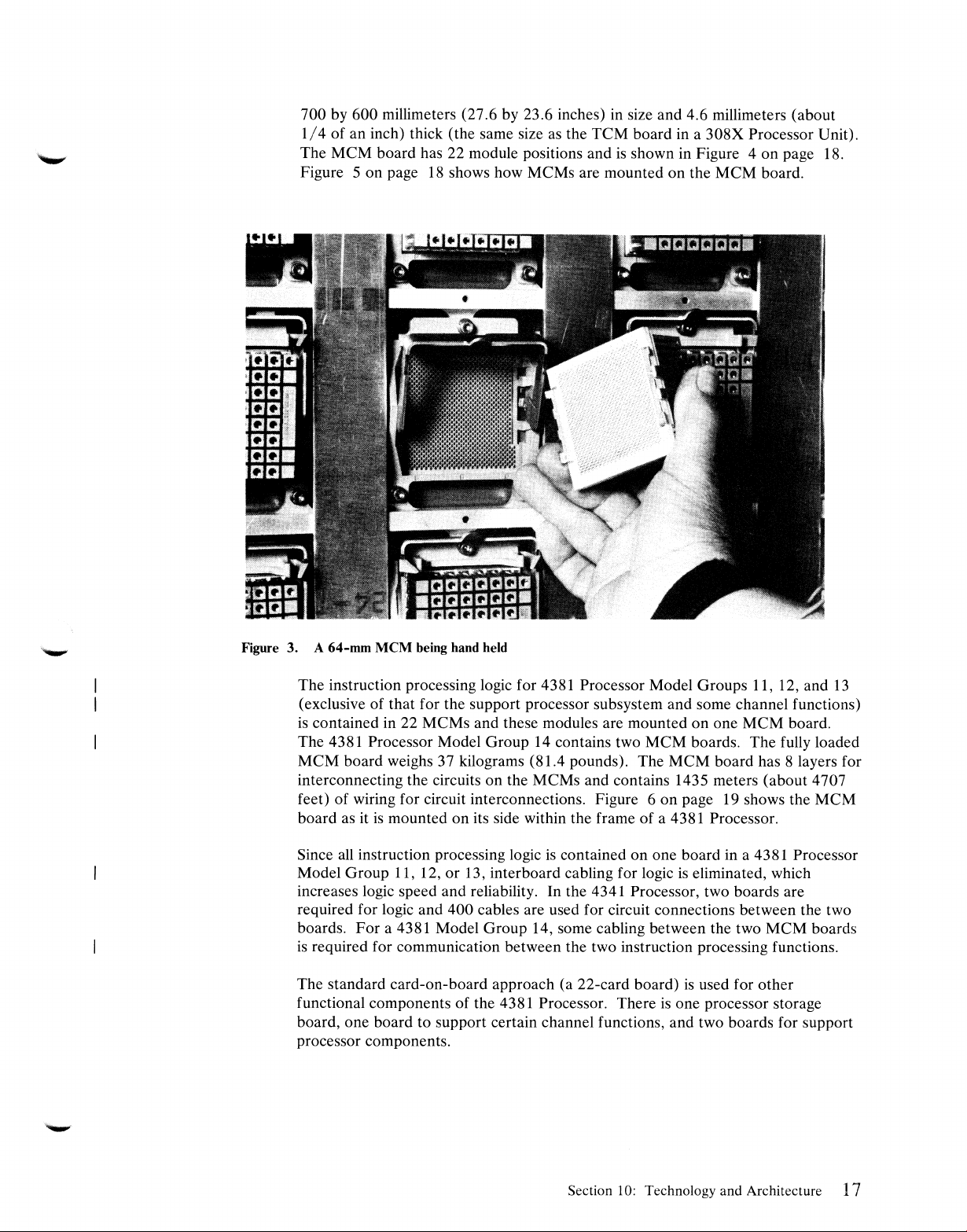
Figure 6.
MCM
board mounted within the 4381 Processor
Logic
Cooling
The high density of the logic circuits on the ceramic substrate used for 4381 logic
required a new method of removing the heat generated. The approach used, called
impingement cooling, permits room-temperature air instead of water to be used to
cool the MCMs.
A ceramic cap covers the chips mounted on the 64-mm ceramic substrate. An
aluminum heat sink
is
mounted over the ceramic cap. Figure 7 on page 20 shows
a 64-mm MCM with a portion of the heat sink cut away. Air to cool the circuit on
the substrate
blown toward the heat sink. The air
is
blown through nozzles (one
is
for each MCM) located about one-eighth of an inch away from the MCMs.
Figure 8 on page 20 shows an impingement cooling nozzle.
The nozzles are attached to the impingement cooling chamber, which receives air
is
from the room. The air from the chamber
blown through the nozzles to the heat
sinks. Thus, the MCMs are cooled individually (or in parallel), as opposed to the
serial approach usually used in air cooling, in which air
is
blown from one side of
the board across the logic. In the serial approach, the circuits closest to the side
from which the air
is
blown receive cooler air than the circuits at the other side of
the board.
Section 10: Technology and Architecture 19
Page 29
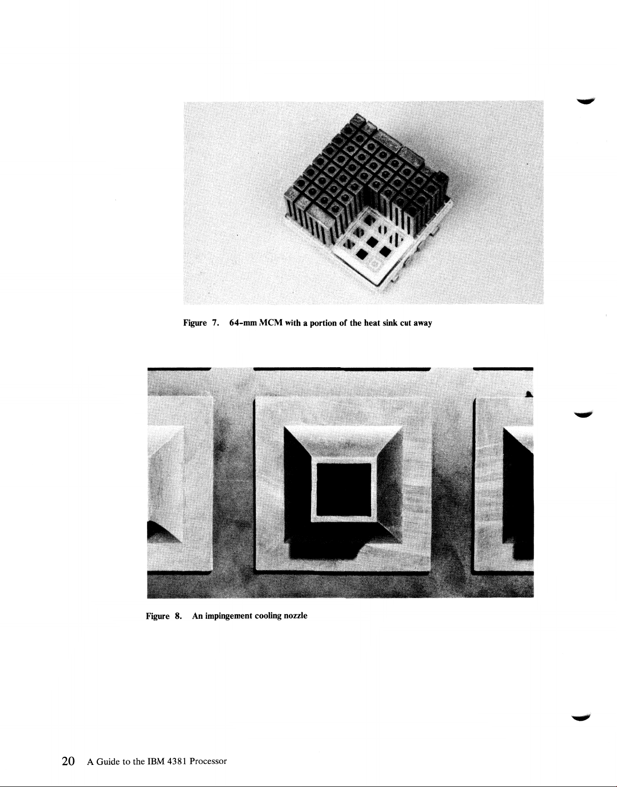
Figure 7. 64-mm
MCM
with a portion
of
the heat sink cut away
20 A Guide
8. An impingement cooling nozzle
Figure
to
the IBM 4381 Processor
Page 30
Storage Technology
10:
10
Architecture
The 64K-bit SAMOS (Silicon and Aluminum Metal Oxide Semiconductor)
(Field Effect Transistor) storage chip that
Processors
Processors. The 64K-bit chips are packaged to provide
per storage card. For processor storage above 16Mb in a 4381 processor, a
256K-bit enhanced SAMOS
storage card. The speed of the 256K-bit chip
(250 ns versus 370 ns).
An array chip that had not previously been used in other IBM processors
implement reloadable control storage and high-speed buffer storage in 4381
Processors. This array chip has a capacity of
faster, lower capacity chip that
implement the high-speed buffer directory and local storage in a 4381 instruction
processing function.
Two architectures are implemented in 4381 Processors: System/370 architecture
and System/370 extended architecture. The mode of processor operation selected
during an initial microcode load (IML) of a 4381 Processor determines the
architecture that
architecture
extended architecture
is
used to implement processor storage of up to 16Mb in 4381
FET
chip
is
contained in other IBM processors
is
functional. When System/370 mode
is
functional. When System/370-XA mode
is
functional.
is
used for processor storage in 4341
lMb
of processor storage
is
used and its packaging provides 2Mb per
is
faster than that of the 64K-bit chip
lK
bytes and a 20-ns cycle time. A
is
selected, System/370
is
selected, System/370
is
used to
FET
is
used to
System/370
Architecture
The System/370 architecture implemented in 4381 Processors includes nearly all
the facilities defined for System/370,
of
are implemented.
The System/370 architecture implemented in 4381 Processors does not include the
following facilities that are defined for optional implementation in System/370
processors:
• Extended machine check logout (that processor-dependent data logged
• Direct Control (READ DIRECT and WRITE DIRECT) instructions. The
• Suspend and resume
as
described in
Operation (GA22-7000). Basic control (BC) and extended control (EC) modes
beginning at the processor storage address specified in control register
15-normally
to 3 51, and the processor-dependent
beginning at the address in the word
external signals facility in 4381 Processors provide the six external interruption
lines included in the Direct Control facility without the two instructions READ
DIRECT and WRITE DIRECT
location 512), the processor-dependent logout to locations 256
I/
0 extended logout (that data logged
at
processor storage location 172)
IBM
System/
3 70 Principles
Section 10: Technology and Architecture
21
Page 31
• Multiprocessing (includes SET PREFIX, STORE PREFIX, SIGNAL
PROCESSOR, and STORE CPU ADDRESS instructions)-implemented in
14
4381 Model Groups
and 3 only
• Channel Set Switching (CONNECT CHANNEL SET and DISCONNECT
CHANNEL SET instructions)
• Compatibility features for emulation of other processors
(1401/1440/1400
Compatibility, for example)
• Certain control program assists (such
OS/DOS
Emulation)
OS/VSl
assist, APL assist, and
as
• Certain processor dependencies
Control and problem programs written for System/370, 4300 System/370 mode,
or 30XX Processors can be run without modification in a 4381 Processor operating
in System/370 mode that has a comparable hardware configuration, with the
following exceptions:
1.
Programs that depend on facilities that are not defined in the System/370
architecture for 4381 Processors (READ DIRECT, WRITE DIRECT, Channel
Set Switching instructions, for example)
2.
Time-dependent programs. (They may or may not run correctly.)
3.
Programs that depend on results defined in the
Operation (GA22-7000) to be unpredictable or processor-dependent
4.
Programs that use unassigned fields in processor formats (instruction formats,
System/370
Principles
of
for example) that are not explicitly made available for program use
5.
Programs that depend on interruptions caused by errors, such
as
unassigned
operation codes or command codes
System/370 architecture
as
implemented in 4381 Processors provides the ability to
execute:
• 4300 System/370 mode control and problem programs that are not
time-dependent or 4300 Processor-dependent
• 4300 problem programs that are designed to operate with 4300 ECPS:VSE
mode control programs and that are not time-dependent or 4300
Processor-dependent. (A 4300 ECPS:VSE mode control program cannot
execute in a 4381 Processor.)
• System/370 or 30XX control and problem programs that are not
time-dependent or System/370 processor-dependent
• System/360 control and problem programs that are not time-dependent or
System/360 processor-dependent
22 A Guide to the IBM 4381 Processor
Page 32

System/370
Extended
Architecture
System/370 extended architecture
exclusions and a set of functional extensions. The new facilities provided by
System/370 extended architecture
following:
A 31-bit addressing capability that provides for addressing more than two
gigabytes (2G-bytes) of virtual and real storage
• Dynamic channel subsystem architecture that provides additional channel
control functions that are designed to improve
• An expanded trace capability that provides for branch tracing, address space
tracing, and explicitly initiated tracing
• Page protection, which can be used to prevent storing into selected virtual
storage pages (see Section 50)
• An instruction (START INTERPRETIVE EXECUTION) to handle
interpretive instruction execution that provides a mechanism for implementing
virtual machine support
A sort microcode assist
The new capabilities provided in System/370 extended architecture are designed to
extend the functional capabilities of System/370 architecture while maintaining
compatibility between the two architectures for problem programs. The instruction
set for System/370 extended architecture includes all the problem state and
semiprivileged instructions defined for System/370 mode of operation (including
MOVE INVERSE).
is
System/370 architecture with certain
as
implemented in the 4381 Processor are the
1/0
performance
The instruction set for System/370 extended architecture contains all the privileged
instructions defined for System/370 architecture except the following:
• INSERT STORAGE KEY (ISK)
• SET STORAGE KEY (SSK)
RESET REFERENCE BIT (RRB)
CLEAR CHANNEL (CLRCH)
I/
CLEAR
• HALT DEVICE (HDV)
HALT
RESUME
START
START
0 ( CLRIO)
1/0
(HIO)
I/O
(RIO)
1/0
(SIO)
1/0
FAST RELEASE (SIOF)
Section
10:
Technology and Architecture
23
Page 33

STORE CHANNEL ID (STIDC)
TEST CHANNEL (TCH)
TEST
1/0
(TIO)
The following instructions are implemented in System/370 extended architecture
but not in System/370 architecture:
• BRANCH AND SA VE AND SET MODE (BASSM)
BRANCH AND SET MODE (BSM)
DIVIDE-extended (DXR)
INSERT PROGRAM MASK (IPM)
START INTERPRETIVE EXECUTION (SIE)
TRACE
CLEAR
•
HALTSUBCHANNEL(HSCH)
MODIFY SUBCHANNEL (MSCH)
• RESET CHANNEL PA TH (RCHP)
RESUME SUBCHANNEL (RSCH)
SET ADDRESS LIMIT (SAL)
SET
START
STORE CHANNEL PATH STATUS (STCPS)
STORE CHANNEL REPORT WORD (STCRW)
STORE SUBCHANNEL (STSCH)
TEST PENDING INTERRUPTION (TPI)
(TRACE)
SUB CHANNEL ( CSCH)
CHANNEL
SUBCHANNEL
MONITOR (SCHM)
(SSCH)
TEST SUBCHANNEL (TSCH)
24 A Guide to the IBM 4381 Processor
Page 34

31-Bit
Addressing
The 31-bit addressing capability significantly increases the amount of virtual and
real storage that can be addressed in a virtual storage
bytes versus over 16 million bytes for the 24-bit addressing capability used in 4381
System/370 mode of operation. To maintain problem program compatibility for
System/370 and System/370-XA modes, bimodal operation
System/370-XA mode that permits concurrent execution of problem programs that
use 24-bit addressing and those that use 31-bit addressing.
is
The addressing mode in effect
is
bit 32
addressing
address generated for instructions and instruction operands. It does not control the
size of PER addresses or of the addresses used to access DAT, ASSN, linkage,
entry, and trace tables. These addresses are always
zero, 24-bit addressing mode
is
in effect. The addressing mode controls the size of the effective
determined by bit 32 in the current PSW. When
is
in effect. When bit 32
environment-over
is
supported for
is
one, 31-bit
31
bits in size.
2 billion
Dynamic Channel Subsystem
as
is
in
is
Note that the 24-bit addresses that are generated when 24-bit addressing mode
in effect are converted to 31-bit addresses by the addition of seven high-order
zeros.
The dynamic channel subsystem defined for System/370-XA mode of operation
provides improvements and additional functional capabilities. The major
differences between the channel architecture for System/370-XA mode and
System/370 mode in 4381 Processors are the following:
• Channels are not assigned a channel number. The instruction processor issues
1/0
requests that specify the
specified. All types of
System/370 mode of operation), and instruction processing function execution
continues after any
information from channel control hardware. A new set of
defined for handling
• Channel path management
than by the
to be used to access an
When multiple channel paths exist to a device, the set of paths specified for the
device
Input/Output
Processor supports up to four paths per
1/0
is
inspected in the sequence defined by the installation using the
1/0
1/0
supervisor portion of the control program. The channel path
Control Program, which
1/0
device to be used. A channel
1/0
requests are queued (not just SIOF requests,
request
1/0
is
issued without waiting for any status
1/0
instructions
operations.
is
performed by the channel control function rather
device
is
selected by the channel control function.
is
discussed in Section 20:20. The 4381
1/0
device.
is
not
is
• A dynamic reconnection capability
reconnect a disconnected channel program to the first available channel path to
the device when multiple paths to the device exist, rather than only to the
channel path from which the channel program disconnected. This capability
utilized, for example, by 3880 Storage Control Models 2 and 3 with attached
3380 Model AA4 Direct Access Storage (which has dynamic path selection).
For
devices without dynamic path selection, reconnection occurs only to the
path from which the channel program disconnected.
supported that permits an
Section
10:
Technology and Architecture 25
1/0
device to
is
Page 35

• Faster restart of
1/0
device when ending status for a completed
0 devices
is
provided by dequeuing the next request for an
I/
passed to the instruction processing function.
I/O
operation on the device
is
..,,,.,,,
• A reformatted channel command word (CCW)
is
defined that uses 31-bit
addressing. However, channel programs that use the CCW format defined for
System/370 mode of operation
will
operate in System/370-XA mode for
compatibility purposes. This implementation enables existing programs that
have their own channel programs and that use the
request
1/0
operations to operate with System/370-XA mode in effect
OS/VS
EXCP
macro to
without modification.
• Device addressing
in one configuration. However, in a 4381 Processor, a maximum of 2048
is
expanded to permit up to 65,535 devices to be addressed
1/0
devices can be addressed. Up to 256 channel paths in one system can be
addressed (as in System/370 architecture). However, a maximum of 12
(Model Groups 11, 12, 13,
1,
and 2) or
18
(Model Groups 14 and 3) channels
can be addressed in a 4381 Processor.
The changes implemented in dynamic channel subsystem architecture are designed
to improve
by relieving the operating system
changes affect the operating system
I/0
performance by reducing delays in the start of
1/0
supervisor of path-scheduling functions. The
1/0
control program and channel control
1/0
operations and
microcode rather than problem programs. Byte multiplexer channel, block
multiplexer channel, and data streaming mode definitions are the same for
System/370-XA and System/370 modes of operation, as
is
the physical structure
of the 4381 channel hardware. All differences between channel operations for the
two modes in a 4381 Processor are handled by channel microcode.
Compatibility
Problem state programs that execute in System/370, 30XX, or 4300 processors
(subject to constraints listed for System/370 mode) or in a 4381 Processor
operating in System/370 mode can execute in a 4381 Processor operating in
System/370-XA mode without modification. Programs that operate in supervisor
state and use any of the System/370 mode privileged instructions that are not
implemented for System/370-XA mode cannot execute in a 4381 Processor
operating in System/370-XA mode without modification.
26 A
Guide
to the IBM
4381
Processor
Page 36

Section 20:
4381
Processor Uniprocessor Model Groups
The functional components physically contained within the frames of a 4381
uniprocessor (Model Group 11, 12, 13, 1, or 2) unit are one instruction processing
function, all processor storage, the storage control function, channels, and the
support processor subsystem. Figure 9 shows the logical components of
uniprocessor model groups of tne 4381 Processor.
~tio,,...
Chonne/
Gro11p
ii
A 9 8 7
0f
Model
Mo<lel
321S7u,
3287,
Power
2
2A.
2C,
er
lnetructlan
Processing
F'unctien
Support
lu$
Mopier
P~icol
II
bus
Channel
hardware
Procesaor
Stora99
Stor4199
Centn>l
ftt'!Vlrtd
eperator
console
Optionel
Optional
Optional
Ststem
D skette
Drive 1
gr,~:~.
Qriyt
3278
3279
or
3205•
3278, 3279,
3205•,
or
3268-2/2C
3278, 3279,
3205,
3268-2/2C
3278. 3279,
3205. 3287, or
3288-2/2C
•3205
c<1mot
l>e
mixH
with
nModel
1, IC, 2,
er
2C
3278
Figure 9. Logical components
Section 20: 4381 Processor Uniprocessor Model Groups
RSr
Remote
c
....
eo1.
or
3279
in
a 4381 Processor Model Group 11, 12, 13, 1, or 2
27
Page 37

20:05 Instruction Processing Function
General
Description
The instruction processing function contains all the elements necessary to decode
and execute the instructions in the instruction set for 4381 Processors.
instructions are partially processed by the instruction processing function and
partially processed by channel hardware. Extensive parity checking
the instruction processing function to ensure data validity.
All instruction execution functions and most channel operations are microcode
controlled. Microinstructions are four bytes in length. Reloadable control storage
for the residence of instruction processing function microcode
Certain basic control and service functions are provided for 4381 Processors by the
support processor, a component of the support processor subsystem, instead of by
the instruction processing function. The support processor
controller with its own control storage. The support processor also handles
operations for the operator console device and up to three other display consoles
and/or
the support processor controls diagnostic facilities (see discussions in Sections
20:15 and 60:15).
The instruction processing function in a 4381 Processor Model Group 11, 12, 1, or
2 has a 68-nanosecond cycle time. A 4381 Processor Model Group
nanosecond cycle time. The primary data path within the instruction processing
function and between the instruction processing function and processor storage and
the channels
primary data path implemented in IBM large-scale (System/370 and 30XX)
processors.
printer devices that are directly attached to a 4381 Processor. In addition,
is
eight bytes wide (as in 4341 Processors), which
is
is
a microcoded
is
1/0
is
done within
standard.
13
has a 56-
the widest
1/0
28 A
Guide
to
the
IBM
Elements included in the instruction processing function to perform instruction
execution are instruction buffers for instruction prefetching, an eight-byte-wide
arithmetic logic unit, an eight-byte MQ register, an eight-byte-wide byte shifter, an
eight-byte-wide bit shifter, and external registers. These same elements are
implemented in 4341 Processors and are functionally alike in 4381 and 4341
Processors.
The instruction processing function in 4381 Processors includes facilities like those
in 4341 Processors that are designed to speed up instruction execution. First,
is
during sequential instruction processing, instruction fetching
instruction execution. Unoverlapped instruction fetching usually occurs only when
a successful branch instruction
Second, several functions are performed during the single instruction cycle of 68 or
56 nanoseconds that precedes the execution cycle(s) of each instruction. The
following are performed during the instruction cycle of a 4381 Processor:
instruction decoding, selection of the microcode required to execute the instruction,
calculation of the required storage address using base register and displacement
values for instructions that reference storage, fetching of the contents of the
register 1 specification in RR- and RS-type instructions, testing for any
interruptions, and complete execution of certain instructions (BC and BCR when a
4381
Processor
is
processed.
overlapped with
Page 38

branch
is
not taken, LA when the index register
is
zero, LR, and LTR
instructions).
Third, floating-point additions and subtractions that involve values with equal
exponents, and decimal additions and subtractions may be performed with the
same speed
as
binary additions and subtractions. This
is
made possible by the use
of an eight-byte-wide arithmetic logic unit for floating-point and decimal arithmetic
instructions
as
well
as
for binary arithmetic. Usually, additions and subtractions
performed using binary arithmetic operate much faster than when decimal or
floating-point arithmetic
is
used.
Fourth, decimal arithmetic operations are performed significantly faster
Processors than in intermediate-scale System/370 processors and execute
in
4381
as
fast
decimal operations in certain large-scale System/370 processors. Fifth, an
eight-byte-wide shifter
is
utilized. This shifter allows a shift to be performed in one
cycle instead of multiple cycles.
The shifter
is
also used to align data that
is
not on the proper boundary. The use of
the shifter instead of microcode for the alignment function eliminates in 4381
Processors nearly
System/370 processors when data
Processors, no performance degradation occurs when alignment
all
the performance degradation that
is
not aligned on the correct boundary. In 4381
is
experienced in many
is
performed
within a doubleword. Some degradation occurs when the unaligned data required
spans two doublewords, since both doublewords must be fetched to obtain the
needed data.
The multifunction instruction cycle, eight-byte-wide arithmetic logic unit, and
eight-byte-wide shifter give the instruction processing function the ability to
execute
21
of the 4381 Processor instructions (such as the RR-type and certain
other instructions) in two cycles (one instruction and one execution).
Eight-byte external registers are included in the instruction processing function.
These hardware registers provide data links between instruction processing
function microcode and channel or instruction processing function hardware. The
external registers contain such items
as
the PSW, the time-of-day clock, storage
address registers, the channel storage address register, interruption registers, the
next instruction buffer register, and status registers.
as
The instruction processing function of 4381 Processors has been functionally
improved over the instruction processing function in 4341 Processors in the
following major areas:
Microcode or hardware changes have been made where possible to speed up
the execution of many instructions.
A high-speed hardware multiplier
function (all
43
81
model groups except 1 and 11) to improve binary and
is
implemented in the instruction processing
floating-point multiply operations.
is
System/370 extended architecture
supported (most of the changes required
for this support are in microcode).
More checking circuits are included for error detection to aid in improved fault
isolation (1200 for uniprocessor and 2600 for multiprocessor 4381 model
groups).
Section 20: 4381 Processor Uniprocessor Model Groups 29
Page 39

The instruction processing function contains a data local storage area of 256
doublewords for use during the execution of instructions. This data local storage
contains certain control registers, the general registers, the floating-point registers,
twelve channel work areas, save areas, and work areas.
is
A trace array of 32 entries
trace the addresses of executed microcode. The array
included in the instruction processing function to
is
always updated during
instruction execution and can be set to operate in one of two modes. In one mode,
the trace array contains the addresses of the last 32 microinstructions executed. In
the other mode, the trace array contains the addresses of the last 32
microinstructions that caused switching from one microcode module to another.
is
The trace array
provided to aid in error detection and recovery. The array helps
to indicate the cycle that caused the error when a machine check occurs.
is
A reconfiguration function
contains a spare area for this function. (Reconfiguration
reloadable control storage in a 4381 Model Group 14 or 3 processor).
error occurs during a read from control storage, the read operation
If
the error
is
not corrected, reconfiguration
facility. The failing control storage address
is
and a space
allocated from the spare area. This space
implemented for reloadable control storage, which
is
provided for each
If
a parity
is
retried once.
is
performed by the instruction retry
is
placed in a reconfiguration register
is
then loaded with the
required microcode from the appropriate functional diskette. Thereafter, when the
is
reconfigured address
referenced, the spare area
is
accessed.
Instruction
Set
The operator
not notified when control storage reconfiguration
is
done and no
is
performance degradation occurs. Up to eight errors can be reconfigured. When
is
the ninth error occurs, reconfiguration
is
terminates, and the operator
notified that repair must be performed.
no longer possible, system operation
The address translation facilities provided for System/370 and System/370-XA
modes are discussed in Section 50. Other significant features of the instruction
processing function of 4381 Processors are discussed in the remainder of this
subsection.
all
The standard instruction set for 4381 Processors contains
the instructions
implemented for 4381 Processors (no instructions are optional). The standard
1,
instruction set for a 4381 Processor Model Group 11, 12, 13,
System/370 mode consists of all the System/370 instructions defined in
System/
3 70 Principles
of
Operation (GA22-7000) except those associated with
or 2 operating in
IBM
features not implemented in these 4381 model groups (READ DIRECT, WRITE
I/O,
DIRECT, RESUME
and multiprocessing and channel set switching
instructions).
The standard instruction set for a 4381 Processor operating in System/370-XA
IBM
mode consists of all the instructions defined in
of
Architecture Principles
Operation (SA22-7085).
System/
3 70 Extended
30 A Guide to the IBM 4381 Processor
Page 40

The STORE CPU ID instruction, which permits a program to determine the
is
processor and version of the processor upon which it
processor serial number, stores the following version codes:
X'
06'
•
X'
•
X'
X'
•
X'
•
The DIAGNOSE MSSFCALL instruction
System/370-XA mode of operation.
This instruction supports seven commands and can be issued only by a program
that
the location of a data area in processor storage (up to 2K bytes in size) that
receive completion status for the instruction and any requested configuration
information.
The following DIAGNOSE MSSFCALL commands are implemented in 4381
Processors:
for the Model Group
08'
for the Model Group 12
03'
for the Model Group
02'
for the Model Group 1
00'
for the Model Group 2
is
operating in supervisor state.
11
13
is
implemented in 4381 Processors for
It
is
used by the
It
specifies the function to be performed and
operating and provides the
MVS/XA
operating system.
is
to
SCP INFO (provides processor storage and auxiliary storage sizes)
CHANNEL PATH INFO (provides channels installed and online/ offline
status)
OFF
• VARY CHANNEL PATH
• VARY CHANNEL PATH
READ RESTART REASON (enables the operating system to obtain a
one-byte restart modifier that was entered by the operator and saved in
auxiliary storage after a restart was initiated)
WRITE CONSOLE TEXT (enables the operating system to place display
information for the operator console in auxiliary storage)
• READ LOOP RECORDING (enables a stand-alone dump program to obtain
trace data saved in auxiliary storage to aid in debugging)
The configuration commands are processed by the instruction processing function.
is
The support processor
required to process all the DIAGNOSE MSSFCALL commands.
not involved. The auxiliary storage area
(used to vary a channel path offline)
ON
(used to vary a channel path online)
is
accessed
as
Section 20: 4381 Processor Uniprocessor Model Groups
31
Page 41

Multiply and Add Facility
Elementary
Math
The standard Multiply and
provides the MULTIPLY AND
and
System/370-XA
multiplication
matrix computations to improve the performance
operations (up to
The MULTIPLY
where A, B, and C are vectors and S
normalized, long-format floating-point numbers, while vector C can contain
unnormalized, long-format elements.
A common use for this assist is to have
routine containing this instruction called from high-level language programs as
required.
detailed information about this instruction, see
Assists (SA22- 7094 ).
and
addition operations
35%
AND
The
MADS mnemonic
Add
Facility for all uniprocessor 4381 model groups
ADD
instruction and is functional in
modes. This instruction performs a combination
that
can replace the inner loop
of
the multiply and add
reduction in compute-intensive subroutine execution time).
ADD instruction performs the function A = (B x
is
a scalar. A, B,
an
installation-written Assembler Language
is
supported by the Assembler Language.
IBM
and
S must consist
System/
3 70 Mathematical
Library Facility
The Elementary
Model Group 2.
provides four functions (eight instructions)
floating-point operands. The instructions are
SQER),
(LGCD
two operands are contained in floating-point registers.
EXPONENTIAL
and
Math
It
is
LGCE),
Library Facility feature is standard in
functional in
(EXPD and
and
NATURAL
System/370
that
SQUARE
EXPE),
LOGARITHM
and
System/370-XA
use short-
ROOT
COMMON
(LGND
the
and
LOGARITHM
System/370
of
vector
of
common
S)
of
4381 Processor
modes.
long-format
(SQDR
and
and
LGNE).
+ C
For
It
The
The Elementary
FORTRAN
VM/CMS,
by
up to 64 percent for
The publication
Elementary
Math
Library (EML) Programming
Mathematical Library supports this facility for operation under
MVS/370,
IBM
Math
and
MVS/XA.
the
assisted functions.
System/
Library Facility instructions.
3 70 Mathematical Assists (SA22-7094) describes the
Square Root Facility and Mathematical Function Facility
These two features provide the functions included in
Facility for the 4381 Model Group 2. The Square
4381 uniprocessor model groups and performs
function using long-
The Mathematical Function Facility is standard in 4381 Model Groups 12 and 13
to assist in exponential, common logarithms, and natural logarithm functions using
short-
or
long-format floating point arithmetic. Reductions in compute-intensive
subroutine execution time vary from
or
short-precision floating-point arithmetic.
RPQ
(5799-BTB) for VS
This assist can reduce processor-busy time
the
37%
to
Elementary
Root
Facility
an
assist for the square root
64%
using this facility.
Math
is
standard in all
Library
32 A Guide
to
the IBM 4381 Processor
Page 42
ECPS:MVS
ECPS:MVS
13
privileged instructions and the Page Fault Assist function that are required to
execute MVS with the MYS/System Product-JES2 or MYS/System Product-JES3
program product installed in a 4381 Processor. The provided instructions are the
following:
ADD FRR*
•
FIX PAGE
SVC ASSIST*
•
OBTAIN LOCAL LOCK*
•
RELEASE LOCAL LOCK*
•
OBTAIN CMS LOCK*
•
RELEASE CMS LOCK*
•
TRACE SVC INTERRUPTION
•
TRACE PROGRAM INTERRUPTION
•
TRACE INITIAL SRB DISPATCH
•
is
a standard facility in 4381 uniprocessor model groups.
It
provides
~·
TRACE
•
TRACE TASK DISPATCH
•
TRACE SVC RETURN
13
All
when System/370 mode
instructions identified by an asterisk are utilized. The facilities of ECPS:MVS are
discussed in
Virtual Machine Extended Facility Assist
instructions to be executed directly by an MVS virtual machine without an
interruption and simulation by the
ECPS:MVS and ECPS:VM/370 (described below) can be used concurrently to
improve performance when
environment in a 4381 Processor.
1/0
INTERRUPTION
instructions listed above and the Page Fault Assist function can be utilized
is
in effect. For System/370-XA mode, only the
IBM
System/ 3 70 Assists for
MVS/370
MVS
(GA22-7079).
is
also standard to enable the ECPS:MVS
VM/370
CP (Control Program).
executes in a virtual machine in a
VM/370
Section 20: 4381 Processor Uniprocessor Model Groups 33
Page 43
ECPS:VM/370
Pref
erred
Machine
The ECPS:VM/370 feature
functional only when System/370 mode
Machine Assist, Control Program Assist, Expanded Virtual Machine Assist, Virtual
Interval Timer Assist, and Shadow Table Bypass Assist components. The first four
components are functionally equivalent to the same components of the
ECPS:VM/370 feature for 4341 Processors and the
function for System/370 Models 135, 138, 145, and 148. These components are
designed to improve the performance of the Control Program component of
VM/370. The Shadow Table Bypass Assist function
performance of MVS/SP Version 1 operating in a virtual equals real
machine in a
VM/370
is
standard in 4381 uniprocessor model groups and
environment.
is
active.
It
consists of the Virtual
VM/370
is
hardware assist
designed to improve the
(V=R)
Assist
The standard Preferred Machine Assist feature for all uniprocessor 4381 model
is
groups
performance of MVS/SP Version 1 running in a V
When supported by VM/System Product High Performance Option, Preferred
Machine Assist permits the MVS/SP V
minimum of
operations on dedicated and nondedicated channels.
operative only in System/370 mode.
zR
VM/370
control program support and to perform native
It
is
designed to improve the
=R
preferred virtual machine.
virtual machine to operate with a
1/0
is
virtual
20:10 Storage
The 4381 Processors have a two-level storage system - a small high-speed buffer
storage backed by a large processor storage. The use of a two-level storage system,
in which the instruction processing function works mostly with the high-speed
buffer, significantly reduces the effective processor storage cycle of 4381
Processors and greatly contributes to their high internal performance.
34 A Guide to the IBM 4381 Processor
Page 44

Processor Storage
Processor storage
follows:
4381 Model Group
11
12
13
1
is
available for 4381 Processor uniprocessor model groups
Processor Storage Sizes Storage
in Megabytes (Mb)
4
8
16
8
16
24
32
8
Model
Lil
Mll
Pll
M12
P12
Q12
R12
M13
16 P13
24
32
4
8
16
Q13
Rl3
LI
Ml
Pl
as
2
4
L2
8 M2
16
24
P2
Q2
32 R2
Field upgrades from one processor storage model to another in the same 4381
model group are supported for all uniprocessor model groups. A portion of the
installed processor storage
reserved for processor use and
is
called auxiliary
is
storage.
is
Access to processor storage
made via the storage control function, which
operates under the control of the instruction processing function. The path to and
is
from processor storage
enters/leaves processor storage
16 bytes wide (two doublewords). Data that
is
aligned on a doubleword boundary.
Error checking and correction (ECC) hardware provides automatic detection and
correction of all single-bit processor storage errors and detection of all double-bit
and many multiple-bit errors. Certain double-bit errors can also be corrected by
ECC
logic
is
microcode.
checking on a doubleword basis. The
contained in the storage control function and performs
ECC
feature and double-bit error correction
are discussed in Section 60.
For
Store and fetch protection are standard.
with up to 16Mb of processor storage, one 7-bit storage protection key
4381 uniprocessor configurations
is
provided
Section 20: 4381 Processor Uniprocessor Model Groups 35
Page 45
for each 2K-byte block of processor storage.
For
a 4381 uniprocessor
configuration with more than 16Mb of processor storage installed, one 7-bit
is
storage protect key for each 4K-byte block of processor storage
is
only one key for every 4K bytes
provided in the processor storage above 16Mb.
supported, since
The standard Extended Addressing feature in 4381 Model Groups 12, 13, and 2
permits processor storage above 16Mb to be utilized. The feature provides the
following:
• Extended real addressing, which provides the ability to address up to 64Mb of
real storage using an additional two bits in page table entries to generate a
26-bit real address from a 24-bit virtual address. As implemented in 4381
Model Groups 12, 13, and 2, Extended Addressing permits up to 32Mb of real
storage to be addressed.
• Storage-key 4K-byte block, which permits storage keys to be provided for
and/
2048-byte blocks
or 4096-byte blocks (instead of only for 2048-byte
blocks)
• Storage key instruction extension, which provides the instructions SET
STORAGE KEY EXTENDED, INSERT STORAGE KEY EXTENDED, and
RESET REFERENCE BIT EXTENDED that can specify a 31-bit real address
and can be used regardless of whether keys are provided on a 2048- or
4096-byte block basis
• 31-bit IDAW, which permits an indirect data address word to specify a 31-bit
absolute address
The TEST BLOCK (TB) privileged instruction (not implemented in 4341
Processors)
provided to enable a program to
(1)
determine the usability of a
is
4K-byte block of processor storage and its associated one or two 7-bit protection
keys and (2) perform storage validation by storing zeros in the 4K bytes to attempt
ECC
to set up good
bits in all the doublewords.
The TB instruction specifies the 31-bit real address of a 4K-byte block on a
is
4K-byte address boundary in processor storage that
is
real address
tested for an addressing exception (address outside of installed
processor storage) and violation of low address protection. The real address
to be tested. The specified
is
not
tested for key-controlled protection or segment protection.
is
The condition code
set for a
specified 4K-byte block and its protection keys.
protection key(s) are usable, condition code 0
is
4K-byte block
unusable, one or both of its keys are unusable, or any
combination of block and keys
TB
instruction to indicate the usability of the
If
both the block and its
is
set. Condition code 1
is
unusable.
is
set if the
In 4381 Processors, if the protection keys for the specified 4K-byte block are both
TB
usable the
instruction sets them both to zero.
instruction leaves both keys unmodified. The
If
either key
TB
instruction stores zeros in the
is
not usable the TB
4K-byte block, whether the block or its keys are usable, to attempt to establish
ECC
good
bits.
TB
The
instruction accesses the TEST BLOCK area within auxiliary storage to
determine the usability of the specified 4K-byte block and its two protection keys.
is
There
one internal record for 4K-byte block errors and one internal record for
36 A Guide to the IBM 4381 Processor
Page 46
protect key errors. There
of processor storage and one bit in the protect key record for its one or two
associated keys. A one in a bit position indicates the associated 4K-byte block or
protect key
function inspects the two appropriate bits in the TEST BLOCK internal records,
sets the condition code, and stores zeros in the addressed 4K-byte block and in
both keys if they are both unusable.
The two TEST BLOCK internal records are placed in auxiliary storage during IML.
These two records are maintained on functional diskette
4381 installation with all zeros in both records. During processor operation, any
time a double-bit error consisting of two solid errors or two consecutive protect key
errors occur, the TEST BLOCK internal record in auxiliary storage and that on
functional diskette 1 are updated. Thus, known unusable 4K-byte blocks are saved
across IMLs and power-offs. The TEST BLOCK internal records on functional
diskette 1 are updated
is
unusable. To execute a
is
one bit in the 4K-byte block record for each 4K bytes
TB
instruction, the instruction processing
1,
which
is
shipped to a
as
appropriate whenever processor storage
is
repaired.
..
...._.,
Auxiliary
Storage
The TB instruction
system to build a page frame table that indicates the known unusable 4K-byte page
frames to avoid their assignment. TB should also be issued if an uncorrectable
storage error
unusable block (store good
occurrence of a machine check if the unusable block
referenced.
The UCWs for System/370 mode or the subchannels and control unit blocks for
System/370-XA mode, the
internal records, and certain work areas are located in highest addressed processor
storage. This storage, called auxiliary storage,
program use and
The size of auxiliary storage in bytes for a 4381 Processor Model Group 11, 12,
or 2 operating in System/370 mode
64 times the number of UCWs defined (128 to 2048) rounded up to a 4K
boundary. For System/370-XA mode, auxiliary storage size in bytes for 4381
Model Groups 11, 12,
70 times the number of control units defined
of subchannels defined (up to 2048) rounded up to a 4K boundary.
is
designed to be used during IPL to enable the operating
is
encountered during system operation to attempt to validate the
ECC
bits). Successful validation will prevent the
is
pref etched or inadvertently
1/0
queuing area, a trace area, the TEST BLOCK
is
reserved for processor rather than
is
inaccessible to all programs.
is
56,320 (57,344 for the Model Group 3) plus
1,
and 2
is
103,168 (104,704 for the Model Group 3) plus
(1
to 256) plus 180 times the number
1,
The minimum auxiliary storage requirement for System/370 mode of operation
64Kb (128 UCWs defined), while the maximum requirement
UCWs defined). For System/370-XA mode of operation, a minimum of 112Kb
required (for 0 subchannels and 128 control unit control blocks) and the maximum
requirement
The size of auxiliary storage
address of the first byte of auxiliary storage
check boundary (ACB) register. Any attempt to access an address equal to or
above the ACB register value during program execution results in an addressing
exception program interruption.
is
480Kb (for 2048 subchannels and 256 control unit control blocks).
is
determined during IML. The processor storage
is
calculated and placed in an address
Section
20:
4381
Processor Uniprocessor Model Groups 37
is
184Kb (2048
is
is
Page 47
The contents of auxiliary storage vary depending on the mode, System/370 or
System/370-XA, in effect. During an IML, the required auxiliary storage area
initialized as appropriate, using information contained on the functional diskette(s).
Auxiliary storage for System/370 mode contains the following in the highest to the
lowest addressed locations:
• UCW area with a minimum of 128 and a maximum of 2048 UCWs
• SIOF queuing area
I/
0 trace area
•
• Channel error logout area
• Channel UCW directory area
• Instruction tracing area
• Channel data buffer reconfiguration test data
• Restart text save area
• Two internal records for the TEST BLOCK instruction (one for unusable
protect keys and one for unusable 4K-byte blocks)
is
• Engineering/ scientific assist feature table
• Program event recording area
• Control storage link information
• K-addressable auxiliary storage area of
pointers and data fields used by the instruction processing function (pointers to
the beginning of the other areas in auxiliary storage, the time-of-day clock, the
CPU
timer, the clock comparator, the interval timer, for example).
For
System/370-XA mode, auxiliary storage contains the following in the highest
to the lowest addressed locations:
• Monitoring data area (32 bytes/subchannel)
I/
0 trace area
•
• Channel error log
• CRW (channel report word) queue
• Subchannel area
• Control unit block area (70
bytes/
lK
bytes. This area contains various
control unit)
38 A
Guide
to
the
IBM
• Channel directories
• Channel data buffer reconfiguration test data
4381
Processor
Page 48

1/0
queuing information
• Interrupt area
• Restart text save area
• SIE instruction work area
• Two internal records for the TEST BLOCK instruction
• Instruction tracing area
• Engineering/ scientific assist feature table
• Program event recording area
• Control storage link information
lK
• K-addressable auxiliary storage area of
varies slightly for System/370-XA and System/370 modes.
bytes. The contents of this area
Storage
Control
Function
The storage control function operates under the control of the instruction
processing function to handle all access to processor storage. The following
components are part of the storage control function:
• The TLB for translating virtual storage addresses in instructions to real storage
• The key stack that contains the 7-bit keys for the processor storage installed.
• The
High-speed buffer storage and its directory
addresses for both System/370 and System/370-XA modes (discussed in
Section 50)
Each key consists of four access control (store protection) bits, one fetch
protection bit, one reference bit, and one change bit.
ECC
logic for processor storage (see Section 60)
The input/output
the components of the storage control function and (2) between processor
storage and the instruction processing function
I/O
The
For
those done for the channels), only
used, while 16 bytes are used for fetches/ stores involving processor storage.
data register
fetches/stores involving the instruction processing function (including
(I/O)
data register that
is
64 bytes wide to improve instruction execution speed.
8 bytes of the 64-byte
is
used to transfer data
1/0
data register are
(1)
among
Section 20: 4381 Processor Uniprocessor Model Groups 39
Page 49

High-Speed Buffer Storage
The high internal performance of 4381 Processor model groups
by the inclusion of high-speed buffer storage. The high-speed buffer is a standard
feature and provides high-speed data access for instruction processing function
fetches and stores.
The high-speed buffer storage provided in 4381 uniprocessor model groups
following:
4381 Model
Group
11
12
13
1
2
When the page size in effect
is used in any uniprocessor model group. When a 2K-byte page size is in effect,
half the capacity of the high-speed buffer
Buffer storage control and use are handled entirely by buffer control function
hardware and are transparent
particular program structure in order to obtain close to optimum use of the buffer.
Parity checking is used for data verification in the buffer.
High-Speed Buffer Storage (Kb)
4
32
64
8
32
is
4K bytes, the full capacity of the high-speed buffer
is
used in any uniprocessor model group.
to
the programmer, who need
is
achieved in part
not
adhere to any
is
the
.._,
When a fetch request is made
or data, high-speed buffer storage control determines whether the requested
doubleword is in the high-speed buffer by interrogating the buffer directory, which
indicates the current contents of the buffer.
in the buffer and valid, it is sent directly
without a processor storage reference.
If
the requested doubleword
storage fetch
buffer, and the requested doubleword
When data
updated if the contents
being maintained in the buffer. Processor storage
the high-speed buffer in 4381 Processors
type of buffer.
processor storage fetch is made to obtain the required block of data and load it in
the buffer. The store is then made to the just loaded buffer location and processor
storage is not modified.
If
the data in the buffer location that is
changed while in the buffer, this data must
loaded.
for the requested data in this situation, a swap buffer
data
is
new block of data
time. After the new block is loaded and the requested data
instruction processing function, the data in the swap buffer is written to processor
storage.
is
made, the data is assigned a buffer location and stored in the
is
stored by the instruction processing function, the high-speed buffer
If
the data
In
order to reduce the time the instruction processing function must wait
written to the swap buffer while processor storage
to
overlap most block unload time with processor storage access
by
the instruction processing function for instructions
If
the doubleword requested is present
to
the instruction processing function
is
not
currently in the high-speed buffer, a processor
is
sent to the instruction processing function.
of
the processor storage location being altered are currently
is
not
modified, however, since
is
a store-in, rather than a store-through,
is
not
currently being maintained in the buffer, a
to
receive the new block of data has been
be
unloaded before the new data can be
is
implemented. The changed
is
being accessed for the
is
sent
to
the
is
40 A Guide to the IBM 4381 Processor
Page 50

The channels read into and write from processor storage using the
input/
output
data register in the storage control function. When a channel writes data (input
1/0
operation from an
the affected processor storage address
device), the buffer directory
is
being maintained in the buffer, the
channel writes the data to the high-speed buffer and processor storage
is
modified. Otherwise, the data
written to processor storage only.
When a channel reads data (output operation to an
directory
interrogated, and
if
the required data
is
from the buffer and presented to the channel.
is
interrogated.
1/0
device), the buffer
is
in the buffer and valid, it
If
the buffer does not contain the
If
data from
is
not
is
required data, the channel reads the data from processor storage and the buffer
not modified.
is
The store-in approach used for the high-speed buffers in 4381 Processors
2,
that used in 4341, 4331 Model Group
4361, 308X, and 3090 processors but
like
contrasts with the store-through approach used in the high-speed buffers in
is
System/370 and 303X processors in which processor storage
is
data
to processor storage, since changed buffer data
if
stored in the buffer. The store-in approach reduces the number of accesses
is
written to processor storage only
it must be replaced by another block (or when a buffer purge
store-in approach becomes more and more advantageous
altered whenever
is
required). The
as
the difference between
processor storage and high-speed buffer storage cycle times becomes greater.
is
Buffer reconfiguration, which
If
4381 Processors.
is
the load
tried once more.
done, if possible,
a double-bit error occurs during the loading of a buffer block,
as
part of the instruction retry function. The buffer array in
not implemented in 4341 Processors,
If
the error
is
not corrected, buffer reconfiguration
Model Groups 12, 13, and 2 contains spare space that
is
used for reconfiguration
is
standard in
purposes.
read
is
is
When an uncorrectable storage error occurs in a byte in a buffer block, space in the
is
reconfiguration area
is
to be used for this buffer block. The buffer load
allocated and a bit
continue using the reconfiguration area for that buffer block if the load
is
set to indicate the reconfiguration area
is
retried and operations
is
successful.
If
a load
is
not successful after the reconfiguration (assigned reconfiguration array
is
location
malfunctioning), the buffer block location that caused the error can no
longer be used and the malfunctioning bit in the directory entry for the
malfunctioning block
turned on. The operator
is
notified that degradation
is
is
occurring and system operation continues.
as
Up to eight buffer block errors can be reconfigured
error occurs in a given byte position within a doubleword. When this limit
reached, the operator
Reconfiguration
substitute array for the swap buffer
up to eight errors can be reconfigured
is
notified that the buffer should be repaired.
is
also attempted for errors that occur in the swap buffer. A
is
provided and,
as
long
as
given byte-pair position within a 16-byte data entry in the array.
is
reconfiguration limit
the swap array, the operator
reached or an error occurs in a reconfigured byte position of
is
notified that repair
long as no more than one
is
as
for the high-speed buffer,
no more than one error occurs in a
If
the
is
required.
Operation of the entire high-speed buffer cannot be disabled in a 4381 Processor.
However, utilization of an individual buffer block can be disabled by turning on the
Section 20: 4381 Processor Uniprocessor Model Groups
41
Page 51

malfunctioning bit in the associated directory entry,
is
reconfiguration
not possible.
20:15 Support Processor Subsystem
as
is
done when
Components
and
Functions
The support processor subsystem provides basic operational functions for 4381
is
Processors and
malfunctions. It
rapid fault location and repair, where possible.
The components of the support processor subsystem are the support processor,
support bus adapter, local channel adapter, console attachment adapter and
attached devices, power adapter, power information panel, common
communications adapter for the Remote Support Facility, and two system diskette
drives and associated adapters.
While the support processor subsystem in 4381 Processors has the same types of
functional components
components in this subsystem in 4381 and 4341 Processors are not the same.
Specifically, the support processor in 4381 Processors
more reliable (because of more dense technology) than that in 4341 Processors and
has twice the storage capacity. The 4381 support processor
card (the 4341 support processor requires four cards) and
with the 4341 support processor. In addition, a number of support logic cards have
been eliminated or reassigned to make the support processor subsystem more
efficient and to aid in easier fault location. A dump-to-diskette button on the
processor control panel on the 4381 Processor can be used to dump the contents of
support processor storage to diskette (functional diskette 2). This dump
information can be sent to the IBM Support Center for analysis when error history
is
required to aid in problem determination.
the primary maintenance tool for diagnosing hardware
is
designed to maximize total system availability and to provide
as
those in 4341 Processors, certain of the physical
is
different.
is
It
is
faster and
is
implemented on one
program compatible
The same two-sided diskettes (with a IM-byte capacity) are used in 4381 and 4341
Processors but a different diskette drive
two diskette drives in the 4381 instead of one. The two diskette drives in a 4381
Processor fit in the same space
Two diskette drives are required in a 4381 Processor in order to support
System/370-XA mode of operation. The second diskette drive also allows some
Problem Analysis routines to be kept online for operator use to avoid diskette
changing.
In addition, communication between the support processor and the instruction
processing function has been improved in 4381 Processors when compared with
the 4341 implementation (see discussion under "Support Bus Adapter" in this
subsection).
The microcoded support processor controls the operation of the support processor
subsystem. The support processor subsystem
42 A Guide to the IBM 4381 Processor
is
used in 4381 Processors and there are
as
the single diskette drive in a 4341 Processor.
is
responsible for the following:
Page 52

System initialization functions (IML and IPL), including microcode loading for
the support processor and instruction processing function
• Manual control functions for the operator and customer engineer (such as
instruction step mode, address compare mode, alter/displays)
Control of the two system diskette drives
I/0
• Control of the
console attachment adapter. These devices include the operator console
display and up to three additional display consoles
devices that natively attach to a 4381 Processor via the
and/
or printers.
• System
modes
• Analysis of logout data, the writing of processor logout data and analysis
information (reference code) to functional diskette 1 after an error
initiation of a retry of retryable instructions and interruptions after an error
occurs, and reconfiguration when an uncorrectable error occurs in a
reconfigurable component
• Diagnostic program loading and execution
• Microcode-controlled power sequencing, power monitoring to detect under-
and over-voltage conditions, and temperature monitoring
• Control of the Remote Support Facility and the Remote Operator Console
Facility
Operation of the support processor
operation of the instruction processing function for certain of its functions. During
system operation, while instruction execution occurs, the support processor controls
the operation of the natively attached display consoles and printers. It also
performs power and temperature monitoring under microcode control and, when
necessary, logging of environmental conditions to functional diskette
I/O
configuration definition for System/370 and System/370-XA
is
independent of, and overlapped with,
is
1.
detected,
Whenever a machine check condition occurs, the instruction processing function
stops and the support processor receives control to initiate an instruction retry
operation or machine check interruption in the instruction processing function, as
is
appropriate. While the instruction processing function
processor logs the error to functional diskette 1 and performs error diagnosis using
the logout data to generate a reference code.
Details about the last four functions listed for the support processor subsystem are
covered in Section 60. Manual control functions are discussed in Section 40. The
other functions are discussed in the remainder of this subsection.
Section 20: 4381 Processor Uniprocessor Model Groups 43
operating, the support
Page 53

System Diskette Drives
The two system diskette drives are small read/write drives, located in the front of
the 4381 Processor unit (as shown in Figure 9 on page 27) and accessible to the
operator. They read removable prerecorded disk cartridges (diskettes). Recording
is
done on both sides of the diskette. Space
drives for diskette storage.
A power-on of a 4381 Processor causes the two system diskette drives to be turned
on. Operation of the system diskette drives
and there are no
cause read or write operations to a system diskette drive.
Five diskettes are sent to each 4381 Processor installation. Two identical
functional diskettes (one for backup) for each system diskette drive are provided in
addition to the service diskette. The microcode on the functional diskettes
installation-customized. Functional diskette 1 contains all the microcode required
for a 4381 configuration operating in System/370 mode (instruction processing
function and support processor microcode), the TEST BLOCK internal records,
areas for logout data from the 4381 Processor, most Problem Analysis routines,
some diagnostic programs, and error analysis programs.
Functional diskette 2 primarily provides support microcode and programming for
System/370-XA mode.
configuration operating in System/370-XA mode (all instruction processing
function and that support processor microcode that
System/370-XA mode), the
(IOCP), the Test Case Monitor, Problem Analysis diagnostics, and certain of the
machine speed diagnostics for fault location (see additional discussion of the
functional diskettes in Section 60).
I/
0 instructions or commands that a user program can execute to
It
contains the microcode required for a 4381
I/0
configuration data sets, the
is
provided to the left of the diskette
is
controlled by the support processor
is
is
different for
I/0
Control Program
not
,,._,
For normal system operation, functional diskette 1
drive 1 and functional diskette 2
configuration permits a 4381 Processor to be IMLed for System/370 or
System/370-XA mode of operation and permits the operator to execute Problem
Analysis routines, if necessary, without changing diskettes.
Operation of a 4381 Processor in System/370 mode
two diskette drives (either one)
diskette drive should be repaired as soon
executed with only one operational diskette drive. Two operational diskette drives
are required in order to operate a 4381 Processor in System/370-XA mode.
When the functional diskettes are mounted on the system diskette drives, an IML
of instruction processing function microcode can occur automatically after a
power-on of a 4381 Processor
of operation using the operator console.
is
function
Parity checking
A procedure exists that enables the customer engineer to temporarily patch the
instruction execution function microcode in reloadable control storage or the
support processor. Any patches made are also made to the microcode on the
appropriate mounted functional diskette.
required thereafter, it can be performed using the operator console.
is
used for reloadable control storage during processor operation.
is
mounted on system diskette drive
is
functional. However, the malfunctioning
as
possible because diagnostics cannot be
is
performed. The operator can establish this mode
If
an IML for the instruction processing
is
mounted on system diskette
2.
This
is
possible if only one of the
44 A Guide to the IBM 4381 Processor
Page 54

Note that when processor power
storage, processor storage, and control storage for the instruction processing
is
function
Each functional diskette for a given 4381 Processor contains the processor serial
number and
number on the diskette
IML and a mismatch causes termination of the IML procedure). The functional
diskettes for a given 4381 Processor also contain
specific to that 4381 Processor (such as UCW assignments for System/370 and the
1/0
The system diskette drives are also used for loading and executing diagnostic
routines and are a basic debugging tool for the system. A comprehensive set of
fault-locating diagnostic routines
the service diskette. These routines can be loaded directly from system diskette
drive 2 into the 4381 Processor and executed (see Section 60:15).
lost, and an IML must be performed when power
is
not portable from one 4381 Processor
is
checked against the processor serial number during any
configuration data set for System/370-XA mode) that precludes portability.
is
turned off, the data in support processor
is
turned
to
another (since the serial
1/0
configuration information
is
supplied to each 4381 Processor installation
on
again.
on
System
Initialization
When the power-on/IML pushbutton
microprocessor based (MBC) logic card
support processor, system diskette drives, and adapters connected to the
of the support processor.
Diagnostics resident in storage of the support processor are executed to test the
operation of the support processor and the system diskette drives and adapters.
these tests execute successfully, the resident microcode for the support processor
loaded from functional diskette
the console attachment adapter, operator console, and power controller adapter are
then loaded into the support processor and executed. The power controller adapter
is
initialized if no errors occur.
When the bootstrap functions have completed successfully, the support processor
loads its own control storage and reads the IML program for the instruction
processing function from functional diskette
console
balance of the 4381 Processor
channel hardware, Channel-to-Channel Adapter (if installed), and
channel-attached
position are powered on, in the sequence listed, by power-sequencing microcode.
Powering of the natively displays and printers must be done by the operator using
the
Channel-to-Channel Adapter can be powered off and on individually when
mode
located within the frames of the 4381 Processor.
is
tested and finally the microcode-controlled power-on sequence for the
is
1/0
devices with their power control switch set to the remote
on/
off switch
is
in effect.
on
these units. The instruction processing function and the
CE
mode
is
established using a customer engineer panel that
on
the operator control panel
is
logically activated to power on the
1.
Diagnostics that verify the correct operation of
1.
The path to the primary operator
initiated. The instruction processing function and
is
pressed, a
1/0
bus
CE
is
If
is
If
no errors occur during powering, instruction processing function hardware
initialized
instruction processing function
functional diskette 1 or 2, as appropriate to the mode selected by the operator if
the installation has established execution of an automatic IML at the successful
at
the completion of the power-on sequence. The microcode for the
is
then loaded into reloadable control storage from
Section 20: 4381 Processor Uniprocessor Model Groups
is
45
Page 55

completion of a power-on. After completion of power-on
program load display
is
shown on the operator console.
and/
or IML, the
Natively
Attached
Devices
Up to four devices can be natively attached to a 4381 Processor via the
the support processor. The natively attached devices attach to channel 0 in 4381
uniprocessors and to channel 0 in channel group 0 in 4381 dual processors via the
local channel adapter. The following devices can be natively attached:
• Required 3205 Color Display Console, 3278 Display Console Model 2A, or
3279 Color Display Console Model 2C
Up to three additional devices, which can be any combination of 3205, 3278
Model 2A, and 3279 Model 2C consoles, 3268 Printers Model 2, 3268 Color
Printers Model 2C, and 3287 Model
exception that 3205 displays cannot be installed in a 4381 configuration that
contains a 3278 Model 2A or 3279 Model 2C display
The additional 3205, 3278 Model 2A, or 3279 Model 2C displays can be used as
alternate
The 3287 and 3268 Printers can be used for hard-copy backup of the 3205, 3278
Model 2A, or 3279 Model 2C displays. The 3287 Printer
a print speed of 80 characters per second (Models 1 and
second (Models 2 and 2C). The 3268 Printer provides faster printing (up to 340
characters per second). The 3287 Models
provide printing in colors.
and/
or additional consoles, as supported by the operating system utilized.
1,
lC,
2,
and/or
lC
and 2C and the 3268 Model
2C Printers with the
is
a desktop printer with
lC)
or 120 characters per
1/0
bus of
2C
Support
Bus
Adapter
The support bus adapter provides an interface between the support processor and
the instruction processing function and channel hardware. Via this direct path, the
support processor can access maintenance hardware (maintenance logic chips) in
the instruction processing function and channels.
to
This interface enables the support processor
initialize logic and scan-out operations to obtain status information after an error
detected during processor operation (see discussion of scan-in, scan-out, and scan
rings in Section 60:10). The scan-in and scan-out facilities are used by
maintenance programs to isolate faults and verify repairs. The support processor
also issues commands (such as start clocks and stop clocks) to the maintenance
chips via the support bus adapter interface.
The support bus adapter also provides an interval timing facility for
power-monitoring microcode.in the support processor. This adapter also drives the
system and wait indicators and the lamp test switch on the switch on the operator
control panel.
Implementation of the preceding functions
Processors. However, in 4381 Processors the support bus adapter
microcoded communication between the instruction processing function and the ....,,,
perform scan-in operations to
is
the same in 4381 and 4341
is
is
also used for
46 A Guide
to
the IBM 4381 Processor
Page 56

20:20 Channels
support processor. The scan-in and scan-out functions are used to transfer data
between the two components, for example, data or programs read by the support
as
processor from a diskette drive (such
configuration data set, and
Processors, the local channel adapter interface
In addition, the 4381 instruction processing function can set an interrupt for the
support processor to indicate its services are needed (for example, a state change
occurs, such
by the support processor,
Communication between the operating system and the operator (via the operator
console)
Processors. However, since the local channel adapter
communication between the instruction processing function and the support
processor, communications problems between these components that can arise in a
4341 Processor when channel 0
Processor.
as
a machine check that requires a scan-out). This eliminates polling
is
handled via the local channel adapter in 4381 Processors,
Input/Output
as
is
done in 4341 Processors.
is
the TEST BLOCK internal records,
Configuration Program). In 4341
is
used for such communication.
as
is
not used for
in a hung condition do not arise in a 4381
1/0
in 4341
General Description
The 43
implemented in 4341 Processors, such
and also offer more channels and higher aggregate channel data rates than do 4341
Processors.
One standard and one optional channel group are provided for all uniprocessor
4381 model groups. The standard channel group consists of one byte multiplexer
channel, addressed
channels 1 through 5. Channel 5 can be configured as a byte, instead of a block,
multiplexer channel. The optional channel group (Block Multiplexer Channels,
Additional feature) provides six block multiplexer channels addressed
through
A byte multiplexer channel in a 4381 Processor can handle the concurrent
operation of multiple slower speed devices when operating in byte interleave mode,
while a block multiplexer channel can support interleaved, concurrent execution of
multiple high-speed channel programs.
Each installed byte or block multiplexer channel can have up to eight control units
attached.
local channel adapter. This internal adapter provides attachment of support
processor subsystem devices to this byte multiplexer channel. As a standard
feature, automatic control unit powering
attached to a 43
81
Processors implement advanced channel functions like those
as
block multiplexing and data streaming,
as
channel 0, and five block multiplexer channels, addressed as
B.
For
byte multiplexer channel 0, one control unit position
is
provided for up to 32 control units
81
Processor.
as
channels 6
is
used by the
Comprehensive error checking
hardware. Checking
is
performed on the control logic in most areas, and standard
Section 20: 4381 Processor Uniprocessor Model Groups 4 7
is
incorporated in the basic design of the channel
Page 57
parity checking
processing function.
is
done on the data flow between the channels and the instruction
For System/370 mode of operation, the fast release function of the START
FAST RELEASE (SIOF) instruction
queuing of SIOF instructions. These two functions are inherent in the design of the
channel subsystem for System/370-XA mode of operation. These facilities reduce
the instruction processing function processing time required for an SIOF instruction
when compared with the time required for a START
Optionally, one Channel-to-Channel Adapter can be installed in a 4381 Processor
and attached to any block multiplexer channel. The other channel to which the
adapter
System/370, 30XX, 4341, 4361, 4331,
positions
interconnected via the 4381 Channel-to-Channel Adapter are required. The
adapter operates in burst mode and transfers data at the rate of the lower speed
channel to which it
The Channel-to-Channel Adapter provided for 4381 Processors
equivalent to the adapter provided for System/370 and 4300 processors but
implemented in a higher density technology that reduces its size.
The 3088 Multisystem Channel Communication Unit can also be used to
interconnect 303X, 308X, 3090, 4341, and 4381 processors via block multiplexer
channels.
is
attached can be contained in another 4381 Processor
on
each channel and one nonshared UCW for each of the two channels
is
attached.
is
implemented in 4381 Processors as
1/0
(SIO) instruction.
or
a System/360,
or4321
processor. Three control unit
is
functionally
1/0
is
is
Device Addresses
and
Unit Control Words For
The byte multiplexer channel and each block multiplexer channel installed in a
4381 uniprocessor model group can have 256 device addresses (00 to FF). Any
device addresses can be used for block multiplexer channels 1 through B or for
channel 5 when it
addresses
attached via the local channel adapter and any device addresses other than these
can be used for the
external control units. Thus, only 240 device addresses (000 to OEF) can be
assigned to user devices natively attached to channel 0 or via external control units.
A 4381 Processor can have a minimum of 128 and a maximum of 2048 UCWs as a
standard feature for System/370 mode of operation. UCWs are allocated by the
customer engineer or operator, using the display console. UCWs above 128 are
allocated in groups of 64. Each UCW
storage. Each group of 64 UCWs requires 4K bytes of storage. Thus, a minimum
of 8K bytes and a maximum of 128K bytes are required for UCW storage.
The UCWs allocated are assigned a three-digit reference number 000 to N-1,
where N
000 to 020 are reserved for internal functions (support processor, for example) and
support subsystem devices. In addition, each channel
channel-shared UCW that
1/0
system).
OFO
is
the number of UCWs allocated. UCWs with the reference numbers
devices attached to the channel that are not allocated a UCW (defined to the
to
is
OFF
1/0
System/370
a byte multiplexer channel.
are reserved for support processor subsystem devices
devices attached to the byte multiplexer channel via
is
used to present asynchronous interruptions for any
Mode
For
byte multiplexer channel 0,
is
64 bytes in size and resides in auxiliary
is
assigned one
48 A
Guide
to the IBM
4381
Processor
Page 58
The UCWs defined can be assigned to any of the channels actually present in the
4381 Processor. A maximum of 256 UCWs can be assigned to any one channel.
The customer engineer or operator assigns UCWs to specific channel addresses
as
using the operator console. Each UCW can be designated
shared or nonshared.
A shared UCW can be used by a set of devices, one device at a time. A shared
UCW generally
one of which can be in operation at a time. A nonshared UCW
assigned to only one device. A nonshared UCW
unit that has only one
is
assigned to a control unit that has multiple devices attached, only
is
is
1/0
device attached or that has multiple
one that
designed for use with a control
1/0
devices
is
attached that can operate concurrently.
A channel directory for each channel
is
allocated in auxiliary storage. Each
channel directory has 256 entries, one for each of the possible device addresses for
a channel. A directory entry indicates whether a UCW
is
assigned to the
associated device address, characteristics of the assigned UCW, and characteristics
of the device assigned the associated device address.
A channel directory entry contains the following:
• Reference number of the UCW assigned (all device addresses have a UCW
assigned)
Assigned bit to indicate whether an
1/0
device
is
defined for the associated
device address
• An indication of whether the UCW
is
shared or nonshared (shared bit)
An indication of whether the associated device operates in byte multiplexer
mode
• An indication of whether the associated device must operate in selector mode
rather than block multiplexer mode
• An indication of whether the device
the START
1/0
FAST queuing function
is
attached to a control unit that
is
to use
• An indication of whether the associated device
is
capable of operating in data streaming mode
• An indication of the mode in which channel 5
is
attached to a control unit that
is
to operate (byte or block
multiplexer)
Devices attached to a block multiplexer channel that are capable of block
multiplexing should have the shared and selector mode bits off in their channel
directory entry to indicate allocation of a nonshared UCW that
For
disconnecting.
streaming mode of operation (such as a
devices attached to a control unit that
3880 storage director), the directory entry
is
capable of
is
capable of data
should have the data streaming mode bit on.
The customer engineer or installation operator can select displays associated with
UCWs. The functions provided by the UCW displays enable the customer
engineer/operator to display the allocated UCW reference numbers and the device
addresses they are assigned, and to display and alter the attributes of the UCWs.
Section 20: 4381 Processor Uniprocessor Model Groups 49
Page 59

The alter capability
UCWs. The UCWs for the natively attached displays/printers are preassigned.
is
used to change device addresses and attributes assigned to
Device addresses for natively attached and all other
devices that are not natively attached must be selected during installation.
UCW assignment
for a natively attached device. Changes to UCWs for natively attached devices
become effective immediately.
The channel directory entry for each device address for which a device has not
been assigned (assigned bit
without an assigned
UCW assigned. Thus, if and
been defined as part of the
any status information that may be generated by the undefined device. However, if
any
I/
0 instruction
code
is
generated for the
Subchannels For System/370-XA Mode
For System/370 extended architecture mode of operation, a byte or block
multiplexer channel can have a maximum of 256 device addresses assigned, as for
System/370 mode, and the same channel device addresses
reserved for system use. Up to 2049 subchannels (2048 plus 1 for microcode
usage) can be defined, each of which requires 128 bytes in auxiliary storage. In
addition, each physical control unit attached to a 4381 Processor (up to 256 plus 1
for microcode usage) requires 70 bytes of auxiliary storage.
1/0
devices and UCWs for
is
changed, it becomes effective during the next IML, unless it
is
off) has a UCW assigned. All the device addresses
1/0
device for the same channel have the same channel-shared
1/0
device exists in a 4381 configuration but has not
1/0
configuration, the shared UCW
is
issued to an undefined device, a not operational condition
1/0
instruction.
(OFO
is
used to present
to OFF) are
If
a
is
A channel directory for each channel
256 directory entries per channel. A directory entry
contains subchannel numbers and path management (control unit and device)
information.
For System/370-XA mode of operation, the installation-defined
configuration resides in a data set on functional diskette 2 called the
configuration data set. This data set
IML to construct the
is
not accessed thereafter during normal system operation.
set
When a 4381 Processor
on functional diskette
required for customer engineer checkout of the 4381 system.
enough
An
configuration for the particular 4381 Processor being installed must be created
using the IBM-supplied
used after initial installation of a 4381 Processor to make changes to the
configuration data set to reflect any alteration of the installed
The IOCP for 4381 Processors
Processor to be operating in System/370 mode. It
diskette 2 and
1/0
devices to enable an
1/0
configuration data set that specifies the customer-defined
1/0
portion of auxiliary storage. The
is
shipped, an initial
2.
This initial version defines only the
1/0
Configuration Program (IOCP). The IOCP
is
executed using the operator console for control and specification
is
allocated in auxiliary storage. There are
is
four bytes in size and
1/0
device
1/0
is
accessed by the support processor during
1/0
configuration data
1/0
MVS/XA
configuration data set
I/
0 configuration
It
does not define
system generation to be performed.
is
1/0
I/
0 configuration.
is
a stand-alone program and requires the 4381
is
supplied on functional
provided
is
also
1/0
50 A Guide to the IBM 4381 Processor
Page 60
of
1/0
devices. This
configurations, but it essentially provides the same functions (creation of
configuration data sets and report printing).
is
The IOCP
4381 Processor before an operating system that supports System/370-XA
installed. Input to the IOCP that describes the
by the installation but the customer engineer
configuration data set
Input to the 4381 IOCP consists of definition statements in 80-column card-image
format. This input can be entered from a card reader, a magnetic tape unit, or the
system console. For
maintained
system generation procedure.
statements must be maintained (they cannot be combined with
generation statements).
used to create the initial
as
a separate data set or included in the Stage I input to the
is
a different IOCP from that provided for 308X
1/0
configuration data set
1/0
configuration must be provided
will
actually create the initial
as
part of the installation process
MVS/XA
installations, the IOCP definition statements can be
For
VM/XA
installations, a separate set of IOCP
if
so requested.
VM/370
1/0
at
installation of a
is
1/0
MVS/XA
system
MVS/XA
statements as the
system generation procedure. The
accept either the IOCP channel definition statement (CHPID macro) or its own
CHANNEL macro (but not both types in the same input)
statements. The
on an
example)
The IOCP
procedure from which all CHANNEL statements have been removed and all
required IOCP statements and parameters have been added. The IOCP
non-1/0
(CTRLPROG, GENERATE, for example) and unknown keywords on
device-defining statements unless instructed to flag them as errors.
Therefore, 4381 installations with
only one input data set for both the
1/0
eliminates the chance of inconsistencies between the
for the hardware and that for the
The IOCP permits channels and
configuration but that are not installed in the 4381 configuration to be defined in
the input. This permits one system generation deck to be used
IOCP, the system generation for the 4381 configuration, and the system generation
for another system in the installation (for example, a 303X, 308X, or 3090
Processor Complex with more channels
support of 4381 Processors includes acceptance of the IOCP definition
1/0
definition portion of the input to Stage I of the
MVS/XA
MVS/XA
1/0
definition statement that applies only to the IOCP (CUNUMBER, for
as
well
as
the IOCP ID and CNTLUNIT macros.
will
accept the existing Stage I input to the
definition
configuration data set processing using the IOCP. A common input also
MVS/XA
system generation procedure will ignore any parameter
generation statements contained in the Stage I input
MVS/XA
MVS/XA
MVS/XA
1/0
devices that can be included in a 4381
system generation procedure
as
the channel-defining
MVS/XA
installed need create and maintain
system generation procedure and
1/0
configuration definition
operating system.
as
and/or
1/0
devices).
MVS/XA
system generation
will
1/0
input to the
will
ignore
is
The IOCP
2 using the supplied
definition statements must be supplied even if
one or more existing definition statements. The existing
is
deleted and a new one
support actual modification of an existing
catastrophic errors are detected in the input, the
written if desired.
used to write a new
I/
0 configuration definition statements. The entire set of
is
1/0
configuration data set on functional diskette
all
that
is
written using the supplied input. The IOCP does not
1/0
configuration data set.
1/0
configuration data set
Section 20: 4381 Processor Uniprocessor Model Groups
required
1/0
is
alteration of
configuration data set
If
no
is
51
Page 61
The IOCP also provides four types of configuration reports. These reports are
written to a printer. The Channel Path Summary Configuration Report lists the
1/0
channel paths defined in the
each listed channel path. The Channel Path Configuration Report provides the
in
information given
devices assigned to the channel path. Other information, such
operation (data streaming or DC interlock) used by the control units attached to
each channel,
1/0
The
their characteristics and attachment to the 4381 Processor (control unit and
channel paths and subchannel type assignment, for example). The Logical Control
Unit Report shows how IOCP has grouped control units and
performance data gathering.
Two different
The two
One
data set using the operator console. The currently active data set
auxiliary storage area must be built.
Information about the IOCP
Configuration Program User's Guide and Reference Manual, GC24-3964.
Device Configuration Report lists the
1/0
configuration data sets are physically identified
1/0
configuration data set
the channel path summary report plus the control units and
is
also given.
1/0
configuration data sets can be present on functional diskette
configuration data and the mode of operation for ..,,,_,
as
the mode of
1/0
devices defined together with
1/0
devices for
2.
as
is
designated the currently active
is
contained in
IBM
4381 Processor Input/Output
data sets 0 and
1/0
configuration
is
read when the
1.
General
Operation
of
the
Channels
The channels in 4381 Processors are microcode- and hardware-controlled.
Operationally, they are integrated channels and, thus, share the use of certain
as
hardware with the instruction processing function, such
byte shifter, and control storage.
I/
The general flow of data between
channels in 4381 Processors
the same
that contains a data-in and a data-out register for transferring data between the
standard
transferring data to
Data
data buffer via a channel-in and channel-out register, each of which
size. One or two bytes are transferred at a time. The channel data buffer contains
one 256-byte buffer area for each channel. Only one channel can be transferring
data to, or receiving data from, the channel data buffer at a time. A set sequence
for handling channel requests
Data
storage via the eight-byte data transfer register and the eight-byte shifter, which
in the instruction processing function. This data transfer
The shifter provides doubleword boundary alignment for data entering processor
storage, when required, and any needed alignment for eight bytes of data entering
the channel data buffer.
as
in 4341 Processors. Each installed channel has an interface controller
1/0
interface to
1/0
is
transferred between the individual interface controllers and the channel
is
transferred between a buffer area in the channel data buffer and processor
is
1/0
devices (one device per controller) at the same time.
0 devices and processor storage via the
shown in Figure 10 on page 53 This data flow
devices.
is
implemented in the channel control hardware.
All
the interface controllers can be
the arithmetic logic unit,
is
two bytes in
is
microcode-controlled.
is
is
52 A Guide
to
the
IBM
4381
Processor
Page 62

A data transfer between processor storage and the channel data buffer handles 64
bytes aligned on a 64-byte boundary, except for beginning and ending transfers for
is
a processor storage buffer that
data transfer requires 1.9 microseconds in a Model Group
microseconds in a Model Group
not located on a 64-byte boundary. A 64-byte
1,
2,
3,
13
or
14
4381 Processor.
11, or 12
~nd
1.7
Processor
Storage
Storage
Control
Byte shifter
I
8 bytes
I
Channel Hardware
Channel Data
Channel Data
Register
I
I
8 bytes
Buffer
256
L....:=..::.Lt:::::es:..J
Channel in
bytes register
Channel
out
register
1or2
bytes
Interface Control
Channel 0
Channel
Channel 2
Channel
3
Channel 4
Channel 5
Channel6
Channel 7
Channel 8
Channel 9
Channel A
Channel B
Standard
1/0
Interface
1
Figure 10. General
flow
of data between the channels and processor storage
Channel control hardware determines the priority for servicing the channels
according to predetermined priorities. When multiple channel trap requests
(requests for microcode service) are outstanding, the lowest numbered channel
with an outstanding request
is
not be serviced again until the other channels with a request outstanding have one
trap request serviced. That is, each channel
the servicing of more than an average of five
installed) or eleven other trap requests between the servicing of two successive trap
requests of its own (each channel
eleventh trap service).
The channels are given priority over the instruction processing function for access
to shared facilities. The channels interfere with instruction processing function
operation when a channel trap request
as
operations
data transfer between processor storage and the channel data buffer,
processing of a UCW, command chaining, data chaining, and status handling.
Section 20: 4381 Processor Uniprocessor Model Groups 53
serviced first. A trap request for this channel
is
guaranteed not to have to wait for
(if
the optional channels are not
is
guaranteed, on an average, every fifth or
is
serviced. Trap requests occur for such
will
Page 63
A 4381 Processor generates less total interference with instruction execution than a
4341 Processor because half the amount of time
data between processor storage and the channel data buffer during an
operation (64 bytes are transferred in 1.9 microseconds in a 4381 uniprocessor
versus four microseconds in a 4341 Processor).
The channels in 4381 Processors do not prefetch CCWs (channel control words)
for input operations. For output operations, a CCW, an IDA W (indirect data
address word), or data can be prefetched.
is
required to transfer a byte of
1/0
Byte
Multiplexer
A reconfiguration function
function
failure occurs during a write from a channel data buffer. Two additional channel
data buffers are associated with each channel group. One of the spare two buffers
for a group can be substituted for a failing channel data buffer in the first channel
group, while the other can be substituted for a failing channel data buffer in the
second channel group.
At
four spare channel data buffers can be reconfigured to handle two failing channel
data buffers in either channel group or one failing channel data buffer in each
channel group.
of the other two spares can be assigned.
The operator
performance degradation occurs.
reconfiguration has been done for two other malfunctioning buffers, a channel data
check error
reconfiguration were not implemented.
Channels
The byte multiplexer channel for 4381 Processors
byte multiplexer channel for System/370, 30XX, and other 4300 processors. A
byte multiplexer channel can operate in byte interleave mode to permit several
slower speed
buffered device to operate. Unbuffered burst mode devices that are subject to data
overrun, such
channel in a 4381 Processor.
is
implemented for the channel data buffers. This
is
invoked by the instruction retry facility when an uncorrectable hardware
any time, two malfunctioning channel data buffers can be reconfigured. The
If
one of the allocated spare channel data buffers malfunctions, one
is
not notified when a channel data buffer
If
a third channel data buffer fails after
is
reported for the affected
1/0
devices to operate concurrently or in burst mode to permit one
as
magnetic tape units, cannot be attached to a byte multiplexer
1/0
operation as would be done if
is
reconfigured and no
is
functionally identical to the
54 A
Guide
to
the
IBM
For byte multiplexer channel input operations in a uniprocessor 4381 model group,
a maximum of up to 2
operation involving a buffered device. The output rate for burst mode buffered
devices equals the device rate in
Mb/sec
small interface and control unit generated delays.
The data rate for byte mode operation depends on other channel activity and the
number of bytes transferred per burst. For one-byte transfers, the maximum data
rate
transfers,
maximum data rate of
achieved only when there
4381
for device rates less than or equal to 2 Mb/sec. These data rates assume
is
24Kb/sec
48Kb/sec
Processor
Mb/sec
for 4381 Model Groups 11, 12, 13, 1, and
is
the maximum data rate, while for four-byte transfers a
96Kb/sec
for channel 0 or 5
Mb/sec
is
is
no activity on any other channel or a console device.
divided by 1 plus the device rate in
possible. The maximum data rates can be
is
possible for a burst mode
2.
For
two-byte
Page 64

For
see
I/
0 devices in
0 via
channel. Thus, a maximum
multiplexer channel 0 in a uniprocessor.
The
the
provides a low-cost
byte
The
device addresses.
transferred from
bytes
Block Multiplexer Channels
The
multiplexer
multiplexer mode, a block multiplexer channel in a 4381 Processor is functionally
equivalent
other
interface
byte
multiplexer channel
IBM
4381 Processor Channel Characteristics,
the
support processor subsystem
the
local channel adapter, which occupies
local channel
1/0
bus
multiplexer channel 0.
local channel
at
a time.
block multiplexer channels in a 4381 Processor
to
4300
and
adapter
of
the
support
method
adapter
It
operates in multibyte
the
local channel
or
selector mode.
a selector
processors. A block multiplexer channel presents a
can
have a maximum
data
rates
when
there
attach
the
of
seven external control units
operates like a channel-to-channel
processor
of
appears as a shared control unit
When
or
block multiplexer channel in
to
channel 0.
attaching support processor subsystem devices
mode
in
adapter
of
to
the
operating in selector
eight control units attached.
is
activity
GA24-3948.
last control unit position
The
the
4381 Processor.
byte
multiplexer channel two
can
on
other
to
byte
multiplexer channel
can
be
adapter
local channel
that
can
operate
System/370,
mode
in block
of
standard
attached
that
adapter
have multiple
block
30XX,
channels,
on
to
byte
connects
to
Data
is
and
1/0
this
The
table below shows
each
for
maximum aggregate
figures are
permissible channel in
Mb/sec.
Standard
Block
4381 Multiplexer
Model Channels Standard
Group
11
12
13 3 3 3 3 2
Like a
each
(O)
in control register 0 determines whether the addressed subchannel
multiplexer channel operates in block multiplexer mode (assuming it
operating in block multiplexer mode)
issued.
programming
12345
33332
33332
1 3 3 3 3 2
2 3 3 3 3 2 14
byte
multiplexer, a block multiplexer channel
of
which
can
The
mode
at
any time.
the
maximum individual block multiplexer channel
each
uniprocessor 4381 configuration as well as
data
rate
of
each
channel group
Optional
Maximum Block Maximum
Aggregate Multiplexer Aggregate Maximum
Channels Optional Aggregate
support
bit
is
set
Group
14
14
14
14
one
I/
to
0 (selector mode)
6789AB
2 2 1 1 1 1
3 3 1 1 1 1
333331
2 2 1 1 1 1
2 2 1 1 1 1
0 operation.
or
selector
The
mode
at
and
the
4381 system. All
Group System
8
10
16
8
8
can
have multiple subchannels,
setting
IPL
of
when a
and
can
a channel
start
be altered
data
22
24
30
22
22
mode
bit
of
a block
is
capable
instruction is
of
by
rate
the
Section 20: 4381 Processor Uniprocessor Model Groups 55
Page 65
Data
Streaming
Mode
Data streaming mode of operation
is
standard for all the block multiplexer channels
present in a 4381 Processor. Data streaming mode enables certain 4381 block
multiplexer channels to handle faster data rates and
all
4381 block multiplexer
channels to handle a longer channel-to-control-unit cable length. Specifically, a
maximum channel-to-control-unit cable length of approximately 122 meters (400
feet)
is
supported for control units that are capable of operating in streaming mode
and a data rate of up to 3
Mb/sec
can be achieved for this cable length for
channels 1 through 4 in uniprocessor 4381 model groups.
When a block multiplexer channel
is
capable of data streaming, both data
streaming and nonstreaming control units can be attached to the block multiplexer
channel. Control units that are capable of streaming must be set by the customer
engineer to operate in streaming or nonstreaming mode for each
1/0
interface to
which they are attached. In addition, control units set to operate in streaming
mode must be allocated UCWs (for System/370 mode of operation) that are
assigned streaming mode. Nonstreaming control units connected to a channel that
is
capable of streaming are still subject to their normal maximum
channel-to-channel -unit cable length and operate at their usual rated speed.
The following can be set to operate in data streaming mode:
• 3880 Storage Control (all models)
EC
3848 Cryptographic Unit with the appropriate
installed
~I
• 3838 Array Processor with the optional Data Streaming feature installed (to
permit operation at 3
Mb/sec)
• 3088 Multisystem Channel Control Unit
For
a 3880 unit, the use of streaming or nonstreaming mode
is
set for each channel
to which the two storage directors are attached. Thus, when no channel-switching
is
feature
nonstreaming, set for the channel to which it
switching
each channel to which the storage director
installed, a storage director always operates in the mode, streaming or
is
connected. When channel
is
installed the mode of operation, streaming or nonstreaming,
is
attached, and the storage director can
is
set for
operate in streaming mode for some channels and nonstreaming mode for others, if
necessary.
For a 3380 Model 1 or 2 with 3330-series,
3340/3344,
3350, 3370, or 3375 drives
attached, each storage director can be set to operate in streaming or nonstreaming
mode. The maximum channel-to-control-unit cable length for a 3880 Model 1 or 2
with 3330-series,
3340/3344,
both streaming and nonstreaming mode of 3880 operation when the 3380
or 3350 drives attached
is
122 meters (400 feet) for
is
attached to a 4381 Processor.
The maximum channel-to-control unit cable length for a 3880 Model
with 3370 or 3375 drives attached
is
61
meters (200 feet) for nonstreaming mode
and 122 meters (400 feet) for streaming mode of 3880 operation when the 3880
1,
2, or 4
is
attached to a 4381 Processor.
56 A Guide
A 3880 Model 2 or 3 storage director with 3380 devices attached must be attached
to channel with a 3
to
the IBM 4381 Processor
Mb/sec
data rate in a 4381 Processor and operate in data
Page 66

streaming mode. The Speed Matching Buffer for 3380 feature can be installed
the storage director but the data rate supported
3380 Direct Access Devices at a 1.5
buffer
is
not supported for the 4381 Processor. The maximum
channel-to-control-unit cable length
Mb/sec
is
122 meters (400 feet).
is
still 3
Mb/sec.
data rate using the speed matching
Operation of
on
SIOF Instruction For
System/370
The fast release function of the SIOF instruction and queuing of SIOF instructions
that are issued to a busy block multiplexer channel
reduce the time required to start
active. However, the queuing facility must be specified for those control units for
which it
SIOF instruction fast release and queuing can be done only for control units
attached to block multiplexer channels (not for control units attached to byte
multiplexer channels). SIOF queuing
nonshared subchannel assigned (not for shared subchannels). An SIOF instruction
that
is
operating in selector mode
Up
to eight control units per channel can be configured for queuing. When a
control unit
which queuing
SIOF queuing, the entire range of addresses that the control unit can recognize as
plugged by the customer engineer (for example 8, 16, or 32 for 3830 Model 2
Storage Control or a 3380 storage director) must be specified, even if fewer than
the maximum number of
the 3850 Mass Storage System, possible real and virtual address ranges must be
specified for each control unit. This address specification requirement permits the
SIOF queuing facility to handle all control unit end conditions (which can be
presented using any device address that
Mode
or
control unit are designed to
1/0
operations. These two facilities are always
is
to be effective.
is
done only for devices that have a
issued to a byte multiplexer channel or to a block multiplexer channel
is
executed
is
configured for SIOF queuing, the range of device addresses for
is
to be active must be specified. To ensure the correct operation of
1/0
devices are actually attached to the control unit.
as
an SIO instruction.
is
associated with a control unit).
For
When a string of direct access devices can be switched between two control unit
functions, two device address ranges (one for each control unit function) should be
specified as usual. The specification of one device address range for one control
unit that covers the range of addresses available to both control units will cause
performance degradation.
The fast release and queuing functions are performed by channel microcode.
Channel, control unit, and device queues are maintained. Space
auxiliary storage to support the queuing function.
Processing of an SIOF instruction for which fast release and queuing can be done
handled
determined.
determined.
2 (busy)
subchannel
the channel queue and a condition code of 0 (request accepted)
instruction processing function then resumes processing.
as
follows by channel microcode. The status of the channel specified
If
the channel
If
the subchannel
is
presented for the SIOF instruction and the request
is
available when the channel
is
busy, the status of the required subchannel
is
already in use or already queued, a condition code
is
busy, the request
Section 20: 4381 Processor Uniprocessor Model Groups 57
is
allocated in
is
is
not queued.
is
placed at the end of
is
generated. The
If
is
the
is
Page 67

If
the requested channel
1/0
operation to the specified channel, control unit, and device.
returned from initial device selection indicates the path
is
presented, since the
0
with no errors
and condition code 0
unit, no queuing
required control unit
placed on the device queue. The instruction processing function resumes
processing after the appropriate condition code has been generated.
is
returned, the request
is
is
available, the channel microcode attempts to start the
is
available, condition code
1/0
operation has been started.
is
placed at the end of the control unit queue
is
presented.
done and condition code 1 ( CSW stored)
is
available but the specified
If
any error status
1/0
If
is
returned for the control
device
If
the status
control unit busy status
is
returned.
is
busy, the request
If
the
is
20:25 Standard
Standard Features
Dequeuing of requests
disconnects), control unit end occurs, or device end occurs. When the
no-longer-busy condition
control unit, or device) are moved to a list for that channel and the operations will
be redriven
When an
processor storage to indicate the busy condition (channel, control unit, or device)
encountered, if any, when the SIOF instruction was first processed.
and
Optional Features
The following are standard features of 43
Processors that are operative for both System/370 and System/370-XA modes:
Binary arithmetic
BRANCH
Byte-oriented operands
Channel indirect data addressing
Channels 0 through 5, which can be configured
multiplexer channels or two byte and four block multiplexer channels
Command retry for block multiplexer channels
Conditional Swapping
Control Unit Powering (for up to 32 control units)
CPU
Data
Decimal arithmetic
Dual Address Space Facility
ECC
ECPS:MVS (tracing functions not implemented for System/370-XA mode)
EC
Elementary Math Library Facility (Model Group 2 only)
Expanded machine check interruption class
• Extended Addressing (Model Groups 12, 13, and 2 only)
Floating-point arithmetic
as
soon
1/0
operation terminates, a delay code
and SAVE instructions
timer and clock comparator (one microsecond resolution)
Streaming for all installed block multiplexer channels
on processor storage and error correction for certain double-bit errors
mode of operation
is
done when the channel becomes available (a device
is
received, all requests on the associated queue (channel,
as
the current System/370 instruction
is
81
Model Group 11, 12, 13,
is
completed.
stored at location 185 in
as
one byte and five block
1,
and 2
58 A Guide to the IBM 4381 Processor
Page 68

• High-speed buff er
Group
Group
1,
32Kb for the Model Groups 12 and 2, and 64Kb for the Model
13
storage-4Kb
for the Model Group 11, 8Kb for the Model
• Instruction retry
SSM
• Interruption for
instruction
• Low address protection
• Mathematical Function Facility (Model Groups 12 and 13)
• Monitoring feature
• MOVE INVERSE instruction
• Multiply and Add Facility
• Problem Analysis
• Program event recording
• PSW key handling
• Reconfiguration functions
• Reference and change recording
• Reloadable control storage
• Square Root Facility (Model Groups 11, 12, and 13)
• Storage key instruction extensions (ISKE, RRBE, and SSKE instructions)
• Store and fetch protection (one key per 2K-byte block for up to 16Mb
installed or one key per 4K-byte block for Model Group 12, 13, or 2
configurations with more than 16Mb installed)
• Store status
• Support processor subsystem
• System/370 Extended feature (common segment bit, INVALIDATE PAGE
TABLE ENTRY instruction, low address protection, TEST PROTECTION
instruction)
• TEST BLOCK instruction
• Time-of-day clock (one-microsecond resolution)
1,
The following are standard features for 4381 Model Groups 11, 12, 13,
is
that operate only when System/370 mode
in effect:
and 2
• BC mode
• Block multiplexer control bit in control register 0
• Channel masks in control register 2
• Channel retry data in a limited channel logout area
• Dynamic address translation for 24-bit virtual and real addresses using 2K or
4K pages and 64K or 1024K segments
• ECPS:VM/370
• External signals
• Interval timer
• INSERT STORAGE KEY instruction
• Instructions for System/370 architecture (includes all defined except READ
I/O,
DIRECT, WRITE DIRECT, multiprocessing, RESUME
and channel set
switching instructions)
• Limited channel logout
• Machine check external damage code
• Preferred Machine Assist
• Recovery extensions
• RESET REFERENCE BIT instruction
• Segment protection
• SET STORAGE KEY instruction
• STORE CHANNEL ID instruction (and all other System/370
I/0
instructions}
Section 20: 4381 Processor Uniprocessor Model Groups 59
Page 69

• SIOF instruction fast release and queuing (comparable facilities are inherent in
the System/370-XA mode channel subsystem definition)
• VM Extended Facility Assist
128 to 2048 UCWs in increments of 64
1,
The following are standard features for 4381 Model Groups 11, 12, 13,
is
that operate only when System/370-XA mode
Bimodal addressing
Channel subsystem designed for System/370 extended architecture
DIAGNOSE MSSFCALL instruction
Dynamic address translation for 31-bit (or 24-bit) virtual and real addresses
using 4K pages and 1024K segments
Instructions for System/370 extended architecture (includes all defined for
System/370 extended architecture)
Page protection
Sort assist
Tracing
• Up to 2048 subchannels
in effect:
and 2
Optional
Features
1,
Optional features for 4381 Model Group 11, 12, 13,
which can operate with System/370 or System/370-XA mode in effect and can be
field-installed, are:
3205 Color Display Console, 3278 Model 2A Display Console, or 3279 Color
Display Console Model 2C (includes printer-keyboard mode for System/370
mode only and display mode for System/370 and System/370-XA
modes)-required
Block Multiplexer Channels, Additional (provides
channels)
Channel-to-Channel Adapter (one maximum)
Remote Operator Console Facility (specify
Remote Support Facility (recommended specify
feature
feature-no
and 2 Processors, all of
six
block multiplexer
charge)
feature-no
charge)
60 A Guide to the IBM 4381 Processor
Page 70

Section 30:
4381
Processor Multiprocessor Model Groups
30:05 Configuration Description
The 4381 Model Groups 14 and 3 are dual processor configurations that
implement tightly coupled multiprocessing. The 4381 Model Group
contains two instruction processing functions, each of which has its own dedicated
set of channels. The channels attached to one instruction processing function
cannot be accessed by the other instruction processing function. All processor
storage in the 4381 processor unit
functions. The 4381 operates under the control of a single multiprocessing control
program when operating as a dual processor with two executing instruction
processing functions and supports the simultaneous operation of two tasks. System
operation with two instruction processing functions
subsystem of one instruction processing function fails.
The 4381 dual processor configuration cannot be partitioned into two independent
uniprocessor systems. However, it can operate as a single uniprocessor
configuration using either instruction processing function. Thus, 4381 system
operation can continue with degraded performance if one instruction processing
function
nonoperational instruction processing function cannot be accessed by the
operational instruction processing function. Thus, the
as symmetrical as possible with appropriate switching features installed, as
discussed in Section 30:25.
is
malfunctioning. When operating as a uniprocessor, the channels of the
14
is
shared by the two instruction processing
is
also possible if the channel
1/0
configuration should be
or
13
unit
The 4381 dual processor configuration
but the 4381 does not have a system controller or external data controller and
channels are dedicated to an instruction processing function. Thus, channel set
switching
The functional components physically contained within the frames of a 4381 Model
Group 14 or 3 Processor are two instruction processing functions (addressed as 0
and
one storage control function, two sets of channels (one dedicated to each
instruction processor), and one support processor subsystem. Figure
page 62 shows the logical components of a 4381 Model Group 14 or 3 Processor.
As shown in Figure
own control storage, high-speed buffer storage, storage control function, and
support bus adapter. One channel set
function but the local channel adapter
is
not implemented in a 4381 Processor.
1), all processor storage (which
11
on page 62, each instruction processing function has its
Section 30: 4381 Processor Multiprocessor Model Groups
is
similar to the 3081 dyadic configuration
is
shared by the two instruction processors),
11
on
is
dedicated to each instruction processing
is
attached only to channel 0 of the channel
61
Page 71

Sl"_lem
Doaketle
Drive I
System
Diskette
Drive
2
Required 3278
operator 3279
console or 3205
I
optional 3205•, 3287
I
optional 3205, 3287,
I
optional 3205. 3287,
Model
Model
~-----'
3278, 3279,
or
3268-2/2C
3287, 3279,
or 3268-2/2C
3278, 3279,
or
3268-2/2C
set for instruction processing function 0. Processor storage can be accessed by
both instruction processing functions via the storage control function.
Processor
Storage
,----'---8
Channel
hardware
2A,
2C,
1-----1
..
,
Phyalcol
1/0
bus
Support
Processor
Power
RSF'
Remote
Console
Support Proceeaor Sul>ey9tem
Figure 11. Logical components
Loco
I
Channel
Adapter
in
a 4381 Processor Model Group 14 or 3
•3205 cannot
..
Model
1,
1C,
be
2.
mixed
or
with 3278
2C
or
3279
62 A Guide to the IBM 4381 Processor
Page 72

The 4381 Model Group 14 or 3 can be initialized by the operator to operate as a
uniprocessor. The 4381 Model Group 14 or 3 can also be set to operate as a
uniprocessor during system operation by the Alternate
facility of MVS or
nonfunctional.
ACR
When
instruction processor to the operational instruction processor and tries to recover
the tasks that were operational at the time of the failure. The channels of the
failing instruction processor are reset to handle any outstanding
requests. An attempt
channels in the group for the operational instruction processor. The failing
instruction processor and its channel group are varied offline. No more
requests or tasks
attached to channel 0 of the failing instruction processor, the primary console
function
instruction processor if such a console
is
switched to an alternate console attached to channel 0 of the operative
VM/370
receives control it attempts to transfer work from the failing
will
be allocated to these components.
after one instruction processing function becomes
is
made to restart the operational
30: 10 Instruction Processing Function
General Description
is
available.
CPU
Recovery (ACR)
1/0
and reserve
1/0
requests using
If
the primary console
1/0
is
Each of the two instruction processing functions in a 4381 Model Group 14 or 3
contains all the elements necessary to decode and execute the instructions in the
instruction set for 4381 Processors.
instruction processing function and partially processed by channel hardware.
Extensive parity checking
ensure data validity.
All instruction execution functions and most channel operations are microcode
controlled. Microinstructions are four bytes in length. Reloadable control storage
for the residence of instruction processing function microcode
instruction processing function.
Certain basic control and service functions are provided for 4381 Processors by the
support processor, a component of the support processor subsystem, instead of by
the instruction processing function. The support processor
controller with its own control storage. The support processor also handles
operations for the operator console device and up to three other display consoles
and/or
the support processor controls diagnostic facilities (see discussions in Sections
30:
The two instruction processing functions in the 43
56-nanosecond cycle time (68 nanoseconds for a Model Group 3) and are
functionally identical. They are addressed
instruction processing function in the 4381 Model Group 13, as described in
Section 20: 10 under "General Description," but have additional facilities to
support tightly coupled multiprocessing. The Model Group 3 instruction processing
functions are like the Model Group 2 instruction processing function.
printer devices that are directly attached to a 4381 Processor. In addition,
15
and 60: 15).
is
done within the instruction processing function to
1/0
instructions are partially processed by the
is
standard in each
is
a microcoded
81
Model Group 14 have a
as
0 and 1 and functionally like the
1/0
Section 30: 4381 Processor Multiprocessor Model Groups
63
Page 73
The following facilities are implemented in a 4381 Model Group 14 or 3 to support
multiprocessing:
• Prefixing - a method of assigning unique areas of processor storage to
addresses 0 to 4095 for each instruction processor. The SET PREFIX and
STORE PREFIX instructions are provided.
• Processor addressing and STORE CPU ADDRESS instruction - required to
specifically identify each instruction processor. The instruction processor
address (0 or
instruction processor involved and the STORE CPU ADDRESS instruction
enables a program to obtain the address of the instruction processor in which it
is
executing.
• Interprocessor programmed communication via the SIGNAL PROCESSOR
(SIGP) instruction - required to enable an instruction processor to request
services of the other instruction processor and to alert it to conditions to which
it must respond during dual processor mode operations. For example, this
capability
for reconfiguring hardware components, and in recovery procedures that occur
after an instruction processor failure.
1)
is
stored during certain external interruptions to identify the
is
used during the initialization of dual processor mode operations,
In the 4381 Model Group 14 or 3, the CPU reset and initial
orders are not implemented for System/370 mode and the IML SIGP order
not implemented for System/370 or System/370-XA mode. See the Principles
of
Operation
• Interprocessor hardware communication - required to alert an instruction
processor to conditions in the other instruction processor and to synchronize
certain operations in both instruction processors during dual processor mode
operations.
The communication facilities include the following:
Synchronization of the two physical time-of-day clocks to provide one
logical clock for the dual processor configuration
Malfunction alert indication sent to the operational instruction processor
when one instruction processor enters the clock stopped state because of a
machine check error
High-speed buffer intercommunication to permit the buffer storage
controls to ensure that all real storage references by each instruction
processor result in access to the most current copy of the addressed data.
This communication
Buffer Storage."
The address translation facilities provided for System/370 and System/370-XA
modes for all 4381 model groups are discussed in Section 50. Other significant
features of the instruction processing functions in 4381 Model Groups 14 and 3 are
discussed in the remainder of this subsection.
manuals for the orders provided for the SIGP instruction.
is
discussed
in
Section 30:
15
CPU
reset SIGP
under "High-Speed
is
64 A Guide to the IBM 4381 Processor
Page 74
Instruction
Set
The standard instruction set for 4381 Processors contains
all
the instructions
implemented for 4381 Processors (no instructions are optional). The standard
instruction set for a 4381 Model Group 14 or 3 Processor operating in System/370
IBM
mode consists of all the System/370 instructions defined in
Principles
implemented in the 4381 Model Group
WRITE DIRECT, RESUME
of
Operation (GA22-7000) except those associated with features not
14
or 3 Processor (READ DIRECT,
I/0,
and channel set switching instructions). The
System/
4381 Model Group 14 or 3 has the same instruction set for System/370 mode
3 70
as
uniprocessor 4381 model groups plus the multiprocessing instructions previously
described.
The standard instruction set for a 4381 Processor operating in System/370-XA
mode consists of all the instructions defined in
of
Architecture Principles
Operation (SA22-7085).
System/
3 70 Extended
IBM
The STORE CPU ID instruction, which permits a program to determine the
is
processor and version of the processor upon which it
processor serial number, stores a version code of
X'Ol'
14 and of
is
identified
The DIAGNOSE MSSFCALL instruction
for System/370-XA mode of operation.
for the 4381 Model Group 3. The instruction processing function
as
0 or 1 by bits 8 through
11
of the stored field.
is
implemented in all 4381 Processors
It
is
used by the
operating and provides the
X'04'
for the 4381 Model Group
MVS/XA
operating
system. This instruction supports seven commands and can be issued only by a
program that
operating in supervisor state.
It
specifies the function to be
is
performed and the location of a data area in processor storage (up to 2K bytes in
is
size) that
to receive completion status for the instruction and any requested
configuration information.
The following DIAGNOSE MSSFCALL commands are implemented in 4381
Processors:
• SCP INFO (provides processor storage and auxiliary storage sizes)
CHANNEL PATH INFO (provides channels installed and online/offline
status)
OFF
• VARY CHANNEL PATH
(used to vary a channel path offline)
• VARY CHANNEL PATH ON (used to vary a channel path online)
• READ RESTART REASON (enables the operating system to obtain a
one-byte restart modifier that was entered by the operator and saved in
auxiliary storage after a restart was initiated)
• WRITE CONSOLE TEXT (enables the operating system to place display
information for the operator console in auxiliary storage)
• READ LOOP RECORDING (enables a stand-alone dump program to obtain
trace data saved in auxiliary storage to aid in debugging)
Section 30: 4381 Processor Multiprocessor Model Groups 65
Page 75

Other Features
30:15 Storage
The configuration commands are processed by the instruction processing function.
The support processor
required to process
The Multiply and Add Facility, Square Root Facility, Mathematical Function
Facility, ECPS:MVS, ECPS:VM/370, and Preferred Machine Assist features are
standard in 43
The Multiply and Add Facility, Elementary Math Library Facility, ECPS: MVS,
ECPS:VM/370, and Preferred Machine Assist features are standard in 4381
Model Group 3 Processors (see discussions of these features in Section 20:05).
81
is
not involved. The auxiliary storage area
all
the DIAGNOSE MSSFCALL commands. ..,,_.,
Model Group 14 Processors.
is
accessed as
Processor Storage
The 4381 Model Group 14 or 3 Processor has a two-level storage
high-speed buffer storage in each instruction processing function backed by shared
large processor storage. The use of a two-level storage system, in which the two
instruction processing functions work mostly with the two high-speed buffers,
significantly reduces the effective processor storage cycle of the 4381 Model Group
14 or 3 and greatly contributes to its high internal performance.
Processor storage
24Mb, and 32Mb (Models P14,
Group 3 in sizes of 8Mb, 16Mb, 24Mb, and 32Mb (Models M03, P03, Q03, and
R03, respectively). Field upgrades from one processor storage model to another in
the same 4381 model group are supported. A portion of the installed processor
storage
Access to processor storage
operate under the control of the instruction processing functions. The path to and
from processor storage
enters/leaves processor storage
Error checking and correction (ECC) hardware provides automatic detection and
correction of
and many multiple-bit errors. Certain double-bit errors can also be corrected by
microcode.
feature and double-bit error correction are discussed in Section 60.
is
reserved for processor use and
is
available for the 4381 Model Group
Ql4,
and R14, respectively) and for the Model
is
called auxiliary storage.
is
made via the storage control functions, which
is
16 bytes wide (two doublewords). Data that
is
aligned on a doubleword boundary.
all
single-bit processor storage errors and detection of all double-bit
ECC
logic performs checking on a doubleword basis. The
14
system-
in sizes of 16Mb,
a small
ECC
Store and fetch protection are standard. For a 4381 Model Group 14 or 3 with no
more than 16Mb of processor storage, one 7-bit storage protection key
for each 2K-byte block of processor storage. For a 4381 Model Group 14 or 3
configuration with 24Mb or 32Mb of processor storage installed, one 7-bit storage
protect key for each 4K-byte block of processor storage
one key for every 4K bytes
66 A Guide to the IBM 4381 Processor
is
supported, since only
is
provided in the processor storage above 16Mb.
is
provided
Page 76
The standard Extendeci Addressing feature in the 4381 Model Group 14 or 3
permits processor storage above 16Mb to be utilized. The feature provides the
following:
• Extended real addressing, which provides the ability to address up to 64Mb of
real storage using an additional two bits in page table entries to generate a
26-bit real address from a 24-bit virtual address. As implemented in 4381
14
Model Group
and 3 Processors, Extended Addressing permits up to 32Mb
of real storage to be addressed.
• Storage-key 4K-byte block, which permits storage keys to be provided for
and/
2048-byte
or 4096-byte blocks (instead of only for 2048-byte blocks)
Storage key instruction extension, which provides the instructions SET
STORAGE KEY EXTENDED, INSERT STORAGE KEY EXTENDED, and
RESET REFERENCE BIT EXTENDED that can specify a 31-bit real address
and can be used regardless of whether keys are provided on a 2048- or
4096-byte block basis
• 31-bit IDAW, which permits an indirect data address word to specify a 31-bit
absolute address
The TEST BLOCK (TB) privileged instruction (not implemented in 4341
Processors)
provided to enable a program to
(1)
determine the usability of a
is
4K-byte block of processor storage and its associated one or two 7-bit protection
keys and (2) perform storage validation by storing zeros in the 4K bytes to attempt
ECC
bits in
all
to set up good
the doublewords.
TB
The
4K-byte address boundary in processor storage that
real address
processor storage) and violation of low address protection. The real address
instruction specifies the 31-bit real address of a 4K-byte block on a
is
to be tested. The specified
is
tested for an addressing exception (address outside of installed
is
not
tested for key-controlled protection or segment protection.
is
The condition code
set for a
specified 4K-byte block and its protection keys.
protection key(s) are usable, condition code 0
is
4K-byte block
unusable, one or both of its keys are unusable, or any
combination of block and keys
TB
instruction to indicate the usability of the
If
both the block and its
is
set. Condition code 1
is
unusable.
is
set if the
In 4381 Processors, if the protection keys for the specified 4K-byte block are both
usable the TB instruction sets them both to zero.
instruction leaves both keys unmodified. The
If
either key
TB
instruction stores zeros in the
is
not usable the
TB
4K-byte block, whether the block or its keys are usable, to attempt to establish
ECC
good
The
bits.
TB
instruction accesses the TEST BLOCK area within auxiliary storage to
determine the usability of the specified 4K-byte block and its two protection keys.
is
There
protect key errors. There
one internal record for 4K-byte block errors and one internal record for
is
one bit in the 4K-byte block record for each 4K bytes
of processor storage and one bit in the protect key record for its one or two
associated keys. A one in a bit position indicates the associated 4K-byte block or
protect key
unusable. To execute a
TB
instruction, the instruction processing
is
function inspects the two appropriate bits in the TEST BLOCK internal records,
Section 30: 4381 Processor Multiprocessor Model Groups 67
Page 77
sets the condition code, and stores zeros in the addressed 4K-byte block and in
both keys
The two TEST BLOCK internal records are placed in auxiliary storage during IML.
These two records are maintained on functional diskette
4381 installation with all zeros in both records. During processor operation, any
time a double-bit error consisting of two solid errors or two consecutive protect key
errors occur, the TEST BLOCK internal record in auxiliary storage and that
functional diskette 1 are updated. Thus, known unusable 4K-byte blocks are saved
across IMLs and power-offs. The TEST BLOCK internal records on functional
diskette 1 are updated as appropriate whenever processor storage
The TB instruction
system to build a page frame table that indicates the known unusable 4K-byte page
frames to avoid their assignment. The TB should also be issued
storage error
unusable block (store good
occurrence of a machine check if the unusable block
referenced.
if
they are both unusable.
1,
which
is
is
is
designed to be used during IPL to enable the operating
if
an uncorrectable
is
encountered during system operation to attempt to validate the
ECC
bits). Successful validation will prevent the
is
prefetched or inadvertently
shipped to a
on
repaired.
Auxiliary
Storage
The UCWs for System/370 mode or the subchannels and control unit blocks for
System/370-XA mode, the
internal records, and certain work areas are located in highest addressed processor
storage. This storage, called auxiliary storage,
program use and
The size of auxiliary storage in bytes for a 4381 Processor Model Group 14
operating in System/370 mode
times the number of UCWs defined (128 to 2048) for each instruction processing
function rounded up to a 4K boundary. For System/370-XA mode, auxiliary
storage size in bytes for Model Groups 14 and 3
number of control units defined
subchannels defined (up to 2048) rounded up to a
The minimum auxiliary storage requirement for System/370 mode of operation
104Kb for the Model Group 14 (lOOKb for the Model Group 3) for 128 UCWs
defined for each instruction processing function, while the maximum requirement
344Kb for the Model Group 14 (340Kb for the Model Group 3) for 2048 UCWs
defined for each instruction processing function.
operation, a minimum of 220Kb
unit control blocks) and the maximum requirement
and 256 control unit control blocks.
is
inaccessible to all programs.
1/0
queuing area, a trace area, the TEST BLOCK
is
reserved for processor rather than
is
90,120 (86,016 for the Model Group 3) plus 64
is
192,512 plus 70 times the
(1to256)
is
required (for 128 subchannels and 128 control
plus 180 times the number of
4K
boundary.
For
System/370-XA mode of
is
568Kb for 2048 subchannels
is
is
68 A
Guide
to
the
IBM
The size of auxiliary storage
address of the first byte of auxiliary storage
check boundary (ACB) register. Any attempt to access an address equal to or
above the ACB register value during program execution results in an addressing
exception program interruption.
The contents of auxiliary storage vary depending on the mode, System/370 or
System/370-XA, in effect. During an IML, the required auxiliary storage area
initialized as appropriate, using information contained on the functional diskette(s).
4381
Processor
is
determined during IML. The processor storage
is
calculated and placed in an address
is
Page 78
Auxiliary storage for
lowest addressed locations:
UCW
•
•
area for each instruction processing function with a minimum
a maximum
SIOF queuing area
I/
0 trace area
Channel error logout area
System/370
of
2048
UCWs
mode contains the following in the highest to the
of
128 and
Channel
• Instruction tracing area
• Channel data buffer reconfiguration test
• Restart text save area
Two internal records for the TEST
protect keys and one for unusable 4K-byte blocks)
•
Engineering/
• Program event recording area
Control storage link information
K-addressable auxiliary storage area
pointers and
to the beginning
the
For
System/370-XA
to the lowest addressed locations:
UCW
directory area
BLOCK
scientific assist table
of
lK
data
fields used
of
the
CPU
timer, the clock comparator, the interval timer, for example).
mode, auxiliary storage contains the following in the highest
by
the instruction processing functions (pointers
other
areas in auxiliary storage, the time-of-day clock,
data
instruction (one for unusable
bytes. This area contains various
Monitoring
•
I/
0 trace area
• Channel error log
CRW
•
• Subchannel area
Control unit block area (70
Channel directories
Channel
I/
0 queuing information
data
area (32
(channel report word) queue
data
buffer reconfiguration test
bytes/subchannel)
bytes/control
Section 30: 4381 Processor Multiprocessor Model Groups 69
unit)
data
Page 79
• Interrupt area
Restart text save area
• SIE instruction work area
Two internal records for the TEST BLOCK instruction
• Instruction tracing area
• Engineering/ scientific assist table
• Program event recording area
• Control storage link information
lK
• K-addressable auxiliary storage area of
varies slightly for System/370-XA and System/370 modes.
bytes. The contents
of
this area
Storage
Control
Function
Each storage control function operates under the control of its associated
instruction processing function to handle all access to processor storage. The
following components are part of each storage control function:
• High-speed buffer storage and its directory
• The TLB for translating virtual storage addresses in instructions to real storage
• The key stack that contains the 7-bit keys for the processor storage installed.
• The
• The input/output
addresses for both System/370 and System/370-XA modes (discussed in
Section 50)
Each key consists of four access control (store protection) bits, one fetch
protection bit, one reference bit, and one change bit.
ECC
logic for processor storage - only in the storage control function for
instruction processing function 0 (see Section 60)
Data flow control
(1/0)
data register that
the components of the storage control function and (2) between processor
storage and the instruction processing function
is
used to transfer data
(1)
among
70 A Guide
to
the
IBM
4381 Processor
1/0
The
For fetches/stores involving the instruction processing function (including
those done for the channels), only
used, while 16 bytes are used for fetches/ stores involving processor storage.
data register
is
64 bytes wide to improve instruction execution speed.
8 bytes of the 64-byte
1/0
data register are
Page 80

High-Speed Buffer Storage
The high-speed buffer
instruction processing function fetches and stores. The 43
is
a standard feature and provides high-speed data access for
81
Model Group 14 has
one standard 64Kb high-speed buffer storage for each instruction processing
function. The 4381 Processor Model Group 3 has one standard 32K-byte
high-speed buffer storage for each instruction processing function.
Buffer storage control and use are handled entirely by buffer control function
hardware and are transparent to the programmer, who need not adhere to any
particular program structure in order to obtain close to optimum use of the buffer.
Parity checking
is
used for data verification in the buffer.
The flow of data from each instruction processing function to and from processor
storage via the high-speed buffers in a 43
Figure 12. One
ECC
checking function
functions. The data flow control logic provides a data path between (
checking function and high-speed buffers 0 and 1 for data
from/to
processor storage and (2) high-speed buffers 0 and 1 for interbuffer data
81
Model Group 14 or 3
is
shared by the two instruction processing
fetch/store
is
shown in
1)
operations
the
ECC
transfers.
Processor
Storage
n
v
ECC
Checking
Logic
~a.
u
Doto Flow
Control 0
....
"""
.4t.
,,
High-speed
Buffer
0
.4t.
....
.....
Cross
Interrogation
Controls
,,
Instruction
Processing Processing
Function 0 Function 1
Figure 12. Data flow to and from processor storage
Model Group 14
or
3
...
Doto Flow
~
Control 1
~a.
,,
High-speed
...
...-
Buffer
1
~l
,,
Instruction
via
the high-speed buffers
in
a 4381
Section 30: 4381 Processor Multiprocessor Model Groups
71
Page 81

Cross interrogation controls are provided for the two high-speed buffers to permit
each buffer storage control to access the buffer directory of the other high-speed
buffer.
is
as
General operation of the two high-speed buffers
is
request
made by an instruction processing function (say
follows. When a fetch
O)
for instructions or
data, its high-speed buffer storage control determines whether the requested
is
doubleword
indicates the current contents of buffer
in buffer 0 and valid, it
in high-speed buffer 0 by interrogating buffer directory 0, which
0.
If
the doubleword requested
is
sent directly to instruction processing function 0 without
is
present
a processor storage reference.
If
the requested doubleword
is
not currently in high-speed buffer 0, the cross
interrogation controls are used to search the buffer directory for high-speed buffer
1.
If
the requested doubleword
is
storage fetch
made, the data
and the requested doubleword
is
When data
stored by instruction processing function 0, high-speed buffer 0
is
not in high-speed buffer 1 either, a processor
is
assigned a buffer location and stored in buffer 0,
is
sent to instruction processing function 0.
is
updated if the contents of the processor storage location being altered are currently
0.
being maintained in buffer
Processor storage
high-speed buffer in 4381 Processors
If
of buffer.
the data
is
not currently being maintained in buffer 0, the cross
is
a store-in, rather than a store-through, type
is
not modified, however, since the
interrogation controls are used to search the buffer directory for high-speed buffer
1.
If
the data
processor storage fetch
0.
buffer
storage
is
not currently being maintained in high-speed buffer 1 either, a
The store
is
not modified.
is
made to obtain the required block of data and load it into
is
then made to the just loaded buffer location and processor
is
When a fetch or store request
is
referenced data
1,
the action taken depends on whether the referenced data block in high-speed
not in high-speed buffer 0 but
buffer 1 has been modified.
move the referenced block from buffer 1 to buffer 0 and this block
1.
invalid in buffer
If
the referenced data block has not been modified in buffer 1 and a store request
The fetch or store
was issued, the referenced block
is
data
in buffer
loaded into buffer 0 from processor storage, and store
0.
For
a fetch request, the referenced block of data
from processor storage. The referenced block in buffer 1
is
bit (copy)
set for this block in each buffer directory.
issued for a buffer block whose copy bit
made by instruction processing function 0 and the
is
being maintained in high-speed
If
it has, a buffer-to-buffer transfer
is
then made to the block in buffer 0.
is
invalidated in buffer
is
on, the buffer block
1,
If
is
performed to
is
marked
the referenced block of
is
made to the block
is
loaded in buffer 0
is
not invalidated but a
a write
is
subsequently
is
changed in the
addressed buffer and invalidated in the other buffer.
If
the data in the buffer location that
is
to receive new block of data for a fetch or a
store request had been changed while in the buffer, this data must be unloaded
before the new data can be loaded. In order to reduce the time the instruction
processing function must wait for the requested data in this situation, a swap buffer
is
implemented for each high-speed buffer. The changed data
is
swap buffer while processor storage
being accessed for the new block of data to
is
written to the
overlap most block unload time with processor storage access time. After the new
is
block
loaded and the requested data
the data in the swap buffer
is
written to processor storage.
is
sent to the instruction processing function,
72 A Guide to the IBM 4381 Processor
Page 82

The channels read into and write from processor storage using the
input/
output
data register in the storage control function. When a channel writes data (input
operation from an
the affected processor storage address
the channel writes the data to that high-speed buffer and processor storage
modified. Otherwise, the data
1/0 device), each buffer directory
is
being maintained in a high-speed buffer,
is
written to processor storage only.
is
interrogated.
If
data from
is
not
When a channel attempts a read or write operation, each buffer directory
interrogated.
write
is
required data
and not modified in the other buffer, the channel read or write
processor storage.
present in the other buffer and modified, the block of data
processor storage and then the channel read or write
done
If
the required data
from/to
is
that buffer and processor storage
not present in the local buffer and
If
the required data
is
present in the local buffer, the channel read or
is
not present in the local buffer, but
is
not affected.
is
either not present or present
is
done
is
transferred to
is
done
from/to
is
If
the
from/to
is
processor
storage.
The store-in approach used for the high-speed buffers in 4381 Processors
that used in 4341, 4331 Model Group
2,
4361, 308X, and 3090 processors but
is
like
contrasts with the store-through approach used in the high-speed buffers in
System/370 and 303X processors in which processor storage
data
is
stored in the buffer. The store-in approach reduces the number of accesses
to processor storage, since changed buffer data
is
written to processor storage only
if it must be replaced by another block (or when a buffer purge
is
altered whenever
is
required). The
store-in approach becomes more and more advantageous as the difference between
processor storage and high-speed buffer storage cycle times becomes greater.
Buffer reconfiguration, which
4381 Processors.
the load
is
tried once more.
If
a double-bit error occurs during the loading of a buffer block,
is
not implemented in 4341 Processors,
If
the error
is
not corrected, buffer reconfiguration
is
standard in
is
done, if possible, as part of the instruction retry function. The high-speed buffer
array for each instruction processor in a Model Group 14 or 3 contains spare space
that
is
used for reconfiguration purposes. When an uncorrectable storage error
occurs in a byte in a buffer block, space in the reconfiguration area
a bit
is
set to indicate the reconfiguration area
The buffer load
is
retried and operations continue using the reconfiguration area
for that buffer block if the load
is
successful.
is
to be used for this buffer block.
is
allocated and
If
a load
is
not successful after the reconfiguration (assigned reconfiguration array
location
is
malfunctioning), the buffer block location that caused the error can no
longer be used and the malfunctioning bit in the directory entry for the
malfunctioning block
is
turned on. The operator
is
notified that degradation
is
occurring and system operation continues.
as
Up to eight buffer block errors can be reconfigured
error occurs in a given byte position within a doubleword. When this limit
reached, the operator
Reconfiguration
is
notified that the buffer should be repaired.
is
also attempted for errors that occur in the swap buffer for the
high-speed buffer in instruction processing function
swap buffer
is
provided and,
as
for a high-speed buffer, up to eight errors can be
long as no more than one
0.
A substitute array for the
is
reconfigured as long as no more than one error occurs in a given byte-pair position
within a 16-byte data entry in the array.
an error occurs in a reconfigured byte position of the swap array, the operator
notified that repair
is
required.
Section 30: 4381 Processor Multiprocessor Model Groups
If
the reconfiguration limit
is
reached or
is
73
Page 83

Operation of the entire high-speed buffer for an instruction processing function
cannot be disabled in a 4381 Processor. However, utilization of an individual
buffer block can be disabled by turning on the malfunctioning bit in the associated
directory entry,
as
is
done when reconfiguration
30:20 Support Processor Subsystem
is
not possible.
Components
and
Functions
The support processor subsystem provides basic operational functions for 4381
is
Processors and
malfunctions.
rapid fault location and repair, where possible.
The components of the support processor subsystem are the support processor,
support bus adapter, local channel adapter, console attachment adapter and
attached devices, power adapter, power information panel, common
communications adapter for the Remote Support Facility, and two system diskette
drives and associated adapters.
The support processor subsystem in 4381 Model Groups 14 and 3
like that in uniprocessor 4381 model groups
Note that in a 4381 Model Group 14 or 3 Processor, the natively attached primary
console and up to three additional displays
multiplexer channel 0 for instruction processing function 0 via the local channel
adapter. Thus, if a malfunction prevents operation of instruction processing
function 0, the 4381 cannot be used in uniprocessor mode with only instruction
processing function l operating unless an alternate console
channel in the group for instruction processing function
the primary maintenance tool for diagnosing hardware
It
is
designed to maximize total system availability and to provide
is
functionally
as
described in Section 20: 15.
and/
or printers attach only to byte
is
connected to a
1.
30:25 Channels
General Description
7 4 A Guide
to
the IBM 4 3
The 4381 Processors implement advanced channel functions like those
implemented in 4341 Processors, such
and also offer more channels and higher aggregate channel data rates than do 4341
Processors.
Two standard channel groups, one for each instruction processing function, are
provided for 4381 Model Group 14 and 3 Processors. Each standard channel
group consists of one byte multiplexer channel, addressed as channel 0, and five
block multiplexer channels, addressed as channels 1 through
standard channels in the configuration. Channel 5 in each channel group can be
configured as a byte, instead of a block, multiplexer channel.
81
Processor
as
block multiplexing and data streaming,
5,
providing twelve
Page 84

One channel group (Block Multiplexer Channels, Additional feature)
a 4381 Model Group 14 or
three for each instruction processing function addressed 6 through
18
channels in the configuration. None of the channels in the optional channel
group can be configured as a byte multiplexer channel and the six channels
provided must be divided equally between the two channel groups (three channels
to each).
For System/370 mode operations, the channel group for instruction processing
is
function 0
dual processor or uniprocessor mode operations by instruction processing function
1,
whose channel group cannot be accessed by instruction processing function 0.
Channel set switching, which permits an instruction processor to access the channel
set of another instruction processor in a tightly coupled multiprocessing
configuration,
For
System/370 mode dual processor operations, the operating system determines
the path selected for an
in both channel groups,
executing in either instruction processor can be started by either instruction
processor. However, if a program executing in instruction processor 0 issues a
request for an
instruction processor
dedicated to that instruction processor and cannot be accessed during
is
not implemented in Model Group
I/
0 device that
3.
This feature provides six block multiplexer channels,
14
and 3 4381 Processors.
I/
0 operation.
I/
0 requests for that device that are issued by a program
is
only accessible via a channel in the group for
1,
the request must be started by instruction processor
If
an
I/
0 device
is
accessible via a channel
is
optional for
8,
for a total of
1.
To ensure maximum system availability for System/370 mode operations, the
configuration for a
uniprocessor mode of operation with access to all or most
instruction processing function becomes inoperable. Thus,
possible should be accessible to both instruction processing functions using channel
and control unit switching features to provide at least one channel path to each
device from each channel group. For devices for which programmed switches are
not available, manual switching can be installed to permit the operator to switch
access between the two channel groups. Redundant control units should be
installed for all critical devices and an alternate operator console should be
attached to channel 0 for instruction processing function
For
System/370-XA mode of operation, the microcoded dynamic channel
subsystem can start an
defined for that device regardless of which instruction processor issued the
request.
A byte multiplexer channel in a 4381 Processor can handle the concurrent
operation of multiple slower speed devices when operating in byte interleave mode,
while a block multiplexer channel can support interleaved, concurrent execution of
multiple high-speed channel programs.
Each installed channel can have up to eight control units attached. For byte
multiplexer channel 0 in the channel group for instruction processing function 0,
one control unit position
provides attachment of support processor subsystem devices to this byte
multiplexer channel. As a standard feature, automatic control unit powering
provided for up to 32 control units attached to a 4381 Processor.
43
81
Model Group 14 or 3 should be designed to permit
I/
0 devices if an
as
many
1.
I/0
operation to a device via any channel path that
is
used by the local channel adapter. This internal adapter
I/0
I/0
devices as
is
1/0
is
Comprehensive error checking
hardware. Checking
is
performed on the control logic in most areas, and standard
Section 30: 4381 Processor Multiprocessor Model Groups
is
incorporated in the basic design of the channel
75
Page 85

parity checking
processing function.
For
System/370 mode of operation, the fast release function of the START
FAST RELEASE (SIOF) instruction
queuing of SIOF instructions. These two functions are inherent in the design of the
channel subsystem for System/370-XA mode of operation. These facilities reduce
the instruction processing function processing time required for an SIOF instruction
when compared with the time required for a START
Optionally, one Channel-to-Channel Adapter can be installed in a 4381 Processor
Model Group 14 or 3 and attached to any block multiplexer channel. The other
channel to which the adapter
Processor or a System/360, System/370, 30XX, 4341, 4361, 4331, or 4321
processor. Three control unit positions on each channel and one nonshared UCW
for each of the two channels interconnected via the 4381 Channel-to-Channel
Adapter are required. The adapter operates in burst mode and transfers data at the
rate of the lower speed channel to which it
The Channel-to-Channel Adapter provided for 4381 Processors
equivalent to the adapter provided for System/370 and 4300 processors but
implemented in a higher density technology that reduces its size.
The 3088 Multisystem Channel Communication Unit can also be used to
interconnect 303X, 308X, 3090, 4341, and 4381 processors via block multiplexer
channels.
is
done on the data flow between the channels and instruction
is
implemented in 4381 Processors
1/0
(SIO) instruction.
is
attached can be contained in another 4381
is
attached.
is
functionally
as
1/0
is
is
Device Addresses
and
Unit Control Words For
Each byte multiplexer channel and each block multiplexer channel installed in a
4381 Processor Model Group 14 or 3 can have 256 device addresses (00
For each channel group, any device addresses can be used for block multiplexer
channels 1 through 8 or for channel 5 when it
byte multiplexer channel 0 in the channel group for instruction processing function
0,
addresses
attached via the local channel adapter and any device addresses other than these
can be used for the
control units. Thus, only 240
user devices natively attached to this channel 0 or via external control units. Any
device addresses can be used for byte multiplexer 0 in the channel group for
instruction processing function
Each instruction processing function in a 4381 Processor Model Group 14 or 3 can
have a minimum of 128 and a maximum of 2048 UCWs
System/370 mode of operation. UCWs are allocated by the customer engineer or
operator, using the display console. UCWs above 128 are allocated in groups of
64. Each UCW
64 UCWs requires 4K bytes of storage. Thus, a minimum of 8K bytes and a
maximum of 128K bytes are required for UCW storage.
The UCWs allocated for each instruction processing function are assigned a
three-digit reference number 000 to N-1, where N
allocated. UCWs for instruction processing function 0 with the reference numbers
000 to 030 are reserved for internal functions (support processor, for example) and
OFO
to
OFF
I/
is
64 bytes in size and resides in auxiliary storage. Each group of
System/370
are reserved for support processor subsystem devices
Mode
is
a byte multiplexer channel. For
0 devices attached to byte multiplexer channel 0 via external
de~ice
addresses (000 to OEF) can be assigned to
1.
as
a standard feature for
is
the number of UCWs
to
FF).
76 A
Guide
to
the
IBM
4381
Processor
Page 86

support subsystem devices. In addition, each channel
channel-shared UCW that
1/0
devices attached to the channel that are not allocated a UCW (defined to the
is
used to present asynchronous interruptions for any
is
assigned one
system).
The UCWs defined for an instruction processing function can be assigned to any of
the channels actually present in the channel group for that instruction processor. A
maximum of 256 UCWs can be assigned to any one channel. The customer
engineer or operator assigns UCWs to specific channel addresses using the operator
as
console. Each UCW can be designated
shared or nonshared.
A shared UCW can be used by a set of devices, one device at a time. A shared
is
UCW generally
one of which can be in operation at a time. A nonshared UCW
assigned to only one device. A nonshared UCW
unit that has only one
assigned to a control unit that has multiple devices attached, only
is
is
designed for use with a control
1/0
device attached or that has multiple
one that
1/0
devices
is
attached that can operate concurrently.
is
A channel directory for each channel
allocated in auxiliary storage. Each
channel directory has 256 entries, one for each of the possible device addresses for
is
a channel. A directory entry indicates whether a UCW
assigned to the
associated device address, characteristics of the assigned UCW, and characteristics
of the device assigned the associated device address.
A channel directory entry contains the following:
• Reference number of the UCW assigned (all device addresses have a UCW
assigned)
• Assigned bit to indicate whether an
device
is
defined for the associated
1/0
device address
An
•
indication of whether the associated device operates in byte multiplexer
mode
is
• An indication of whether the UCW
shared or nonshared (shared bit)
• An indication of whether the associated device must operate in selector mode
rather than block multiplexer mode
is
• An indication of whether the device
1/0
the START
FAST queuing function
attached to a control unit that
• An indication of whether the associated device
is
capable of operating in data streaming mode
An indication of the mode in which channel 5
is
attached to a control unit that
is
to operate (byte or block
is
to use
multiplexer)
Devices attached to a block multiplexer channel that are capable of block
multiplexing should have the shared and selector mode bits off in their channel
is
directory entry to indicate allocation of a nonshared UCW that
For
disconnecting.
devices attached to a control unit that
streaming mode of operation (such
as
a 3880 storage director), the directory entry
is
capable of
capable of data
should have the data streaming mode bit on.
Section 30: 4381 Processor Multiprocessor Model Groups 77
Page 87

The customer engineer or installation operator can select displays associated with
UCWs. The functions provided by the UCW displays enable the customer
engineer/operator to display the allocated UCW reference numbers and the device
addresses they are assigned, and to display and alter the attributes of the UCWs.
The alter capability
UCWs. The UCWs for the natively attached displays/printers are preassigned.
is
used to change device addresses and attributes assigned to
Subchannels For
Device addresses for natively attached and all other
devices that are not natively attached must be selected during installation.
UCW assignment
for a natively attached device. Changes to UCWs for natively attached devices
become effective immediately.
The channel directory entry for each device address for which a device has not
been assigned (assigned bit
without an assigned
UCW assigned. Thus,
been defined as part of the
any status information that may be generated by the undefined device. However, if
any
1/0
instruction is issued to an undefined device, a not operational conditional
code
is
generated for the
System/370-XA
For
System/370 extended architecture mode of operation, a byte or block
multiplexer channel can have a maximum of 256 device addresses assigned, as for
System/370 mode, and the same channel device addresses
multiplexer channel 0 for instruction processing function 0 are reserved for system
use. Up to 2049 subchannels (2048 plus 1 for microcode usage) can be defined,
each of which requires 128 bytes in auxiliary storage. In addition, each physical
control unit attached to a 4381 Processor (up to 256 plus 1 for microcode usage)
requires 70 bytes of auxiliary storage.
is
Mode
1/0
devices and UCWs for
If
a
changed, it becomes effective during the next IML, unless it
is
off) has a UCW assigned. All the device addresses
1/0
device for the same channel have the same channel-shared
if
and
1/0
device exists in a 4381 configuration but has not
1/0
configuration, the shared UCW
1/0
instruction.
is
used
(OFO
to OFF) for byte
to
present
is
Subchannels for System/370-XA mode are the same for all 4381 model groups, as
described in Section 20:20.
General Operation
of
the Channels
The channels in 4381 Processors are microcode- and hardware-controlled.
Operationally, they are integrated channels and, thus, share the use of certain
hardware with the instruction processing function, such as the arithmetic logic unit,
byte shifter, and control storage.
The operation of each channel group in a 4381 Model Group 14
the same as the operation of the channels in a uniprocessor 4381 model group, as
described in Section 20:20.
78 A Guide to the IBM 4381 Processor
or
3 Processor
is
Page 88

Byte Multiplexer
Channels
-
The byte multiplexer channel for 4381 Processors
byte multiplexer channel for System/370, 30XX, and other 4300 processors. A
byte multiplexer channel can operate in byte interleave mode to permit several
slower speed
buffered device to operate. Unbuffered burst mode devices that are subject to data
overrun, such as magnetic tape units, cannot be attached to a byte multiplexer
channel in a 4 3
For
byte multiplexer channel input operations, a maximum of up to 2
channel 0 or 5
The output rate for burst mode buffered devices equals the device rate in
divided by 1 plus the device rate in
Mb/sec.
delays.
The data rate for byte mode operation depends on other channel activity and the
number of bytes transferred per burst. For one-byte, two-byte, and four-byte
transfers, the maximum data rates are 28Kb/sec, 56Kb/sec, and 112Kb/sec for
the 4381 Model Group 14 and for channel 5 of the 4381 Model Group
channel 0 of the 4381 Model Group 3, maximum data rates are 24Kb/sec,
48Kb/sec, and
respectively. The maximum data rate can be achieved only when there
activity on any other channel or a console device. For byte multiplexer data rates
when there
Characteristics,
I/
0 devices to operate concurrently or in burst mode to permit one
81
Processor.
is
possible for a burst mode operation involving a buffered device.
Mb/sec
These data rates assume small interface and control unit generated
96Kb/sec
is
other channel activity, see
GA24-3948.
for one-byte, two-byte, and four-byte transfers,
IBM
is
functionally identical to the
Mb/sec
for device rates less than or equal to 2
4381 Processor Channel
Mb/sec
3.
For
is
no
for
Block Multiplexer
I/
0 devices in the support processor subsystem attach to byte multiplexer channel
0 for instruction processing function 0 via the local channel adapter, which
occupies the last control unit position on this channel. Thus, a maximum of seven
external control units can be attached to byte multiplexer channel 0 for instruction
is
processing function 0. There
channel 0 for instruction processing function
The local channel adapter operates like a channel-to-channel adapter that connects
the
1/0
bus of the support processor to byte multiplexer channel
channel adapter provides a low-cost method of attaching support processor
subsystem devices to a channel.
The local channel adapter appears as a shared control unit that can have multiple
device addresses.
transferred from the local channel adapter to the byte multiplexer channel two
bytes at a time.
It
operates in multibyte mode in the 4381 Processor. Data
no local channel adapter for byte multiplexer
1.
0.
The local
Channels
The block multiplexer channels in a 4381 Processor can operate in block
multiplexer or selector mode. When operating
mode, a block multiplexer channel in a
a selector or block multiplexer channel in System/370, 30XX, and other 4300
processors. A block multiplexer channel presents a standard
have a maximum of eight control units attached.
43
in
81
Processor
selector of block multiplexer
is
functionally equivalent to
I/
0 interface and can
is
-
Section 30: 4381 Processor Multiprocessor Model Groups 79
Page 89

The maximum data rate for block multiplexer channels 1 through 5 in each
standard channel group in a 4381 Model Group 14
each for data streaming mode
the ten
Mb/sec.
standard block multiplexer channels
of
operation. The maximum aggregate
is
the
or
3 Processor
sum
of
is 3 Mb/sec
these rates,
data
or
30
rate for
Data Streaming Mode
When the optional channel group is installed in a 4381 Model Group 14, each
the six channels has a maximum data rate of 3
data rate for the nine channels in each group is 18
aggregate data rate
When
the
optional channel group is installed in a 4381 Model Group 3, channel 6
in each channel group has a maximum data rate
8 in each channel group can operate
maximum aggregate data rate
a maximum aggregate
Like a byte multiplexer, a block multiplexer channel can have multiple subchannels,
each
of
which can support one
(0) in control register 0 determines whether the addressed subchannel
multiplexer channel operates in block multiplexer mode (assuming it is capable
operating in block multiplexer mode)
issued. The mode bit is set
programming
Data
streaming mode
present in a 4381 Model Group 14
all (Model Group 14)
to handle faster
longer channel-to-control-unit cable length. Specifically, a maximum
channel-to-control-unit cable length
supported for control units that are capable
data rate
through 8 in each channel group in a 4381 Model Group 14
through 6 in each channel group in a 4381 Model Group 3.
of
up
of
36
of
at
any time.
of
or
data
rates
to 3 Mb/sec
Mb/sec
32
operation is standard for all the block multiplexer channels
certain (Model Group 3) 4381 block multiplexer channels
and
for the two groups.
at
a maximum
of
the nine channels in each group is 16
Mb/sec
to
can
for the two groups.
1/0
operation. The setting
or
0 (selector mode)
or
3 Processor.
all 4381 block multiplexer channels to handle a
of
approximately 122 meters (400 feet) is
be
achieved for this cable length for channels 1
Mb/sec.
of 3 Mb
selector mode when a start instruction is
at
of
operating in streaming mode and a
The maximum aggregate
Mb/sec,
providing a maximum
I sec, while channels 7
of 2 Mb/sec
IPL
and
Data
streaming mode enables
each. The
of
a channel mode bit
can
be
altered
and
for channels 1
Mb/sec
of
of
and
for
a block
of
by
.__
'
Data
streaming mode
discussed in Section 20:20.
SIOF Instruction For System/370 Mode
The fast release function
that
are issued to a busy block multiplexer channel
reduce the time required
in all 4381 model groups, as discussed in Section 20:20.
80 A
Guide
to the
IBM
4381
Processor
of
operation is the same in all 4381 model groups, as
of
the SIOF instruction
to
start
I/
0 operations. These two facilities are the same
and
queuing
or
control unit are designed
of
SIOF instructions
to
Page 90
30:30
Standard
and
Optional Features
Standard
Features
The following are standard features of 4381 Model Group 14 and 3 Processors that
are operative for both System/370 and System/370-XA modes:
• Binary arithmetic
• BRANCH and SA VE instructions
• Byte-oriented operands
• Channel indirect data addressing
• Channels 0 to 5 for each instruction processing function, which can be
as
configured
four block multiplexer channels
• Command retry for block multiplexer channels
• Conditional Swapping
• Control Unit Powering (for up to 32 control units)
• CPU timer and clock comparator (one microsecond resolution)
• Data Streaming for all installed block multiplexer channels
Decimal arithmetic
• Dual Address Space Facility
ECC
•
• Expanded machine check interruption class
• Extended Addressing
• High-speed buffer
• Instruction retry
• Low address protection
• Monitoring feature
• MOVE INVERSE instruction
• Reference and change recording
• Square Root Facility (Model Group 14)
• Store and fetch protection (one key per 2K-byte block for up to 16Mb
• Support processor subsystem
on
ECPS:MVS (tracing functions not implemented for System/370-XA mode)
EC
mode of operation
Elementary Math Library Facility (Model Group 3)
Floating-point arithmetic (including extended precision)
in the Model Group 14 and 32K bytes for each instruction processing function
in the Model Group 3
Interruption for
Mathematical Function Facility (Model Group 14)
Multiply and Add Facility
Multiprocessing
Problem Analysis
Program event recording
PSW key handling
Reconfiguration functions
Reloadable control storage
Storage key instruction extensions (ISKE, RRBE, and SSKE instructions)
installed or one key per 4K-byte block for more than 16Mb installed)
Store status
one byte and five block multiplexer channels or two byte and
processor storage and error correction for certain double-bit errors
storage-64K
SSM
instruction
bytes for each instruction processing function
Section 30: 4381 Processor Multiprocessor Model Groups
81
Page 91

• System/370 Extended feature (common segment bit, INVALIDATE PAGE
TABLE ENTRY instruction, low address protection, TEST PROTECTION
instruction)
TEST BLOCK instruction
Time-of-day clock (one-microsecond resolution)
The following are standard features for 4381 Model Groups 14 and 3 that operate
is
only when System/370 mode
• BC mode
Block multiplexer control bit in control register 0
Channel masks in control register 2
Channel retry data in a limited channel logout area
Dynamic address translation for 24-bit virtual and real addresses using 2K or
4K pages and 64K or 1024K segments
ECPS:VM/370
External signals
Interval timer
INSERT STORAGE KEY instruction
Instructions for System/370 architecture (includes
DIRECT, WRITE DIRECT, RESUME
instructions)
• Limited channel logout
Machine check external damage code
Preferred Machine Assist
• Recovery extensions
RESET REFERENCE BIT instruction
Segment protection
SET STORAGE KEY instruction
STORE CHANNEL ID instruction (and
instructions)
SIOF instruction fast release and queuing (comparable facilities are inherent in
the System/370-XA mode channel subsystem definition)
VM Extended Facility Assist
128 to 2048 UCWs in increments of 64
in effect:
all
defined except READ
I/0,
and channel set switching
all
other System/370
I/0
The following are standard features for 4381 Model Groups 14 and 3 that operate
only when System/370-XA mode
Bimodal addressing
Channel subsystem designed for System/370 extended architecture
DIAGNOSE MSSFCALL instruction
Dynamic address translation for 31-bit (or 24-bit) virtual and real addresses
using 4K pages and 1024K segments
Instructions for System/370 extended architecture (includes all defined for
System/370 extended architecture)
Page protection
Tracing
Sort assist
Up to 2048 subchannels
82 A Guide to the IBM 4381 Processor
is
in effect:
Page 92
Optional
Features
Optional features for 4381 Model Group 14 and 3 Processors, all of which can
operate with System/370 or System/370-XA mode in effect and can be
field-installed, are:
• 3205 Color Display Console, 3278 Model 2A Display Console, or 3279 Color
Display Console Model 2C (includes printer-keyboard mode for System/370
mode only and display mode for System/370 and System/370-XA
modes)-required feature
• Block Multiplexer Channels, Additional (provides six block multiplexer
channels)
• Channel-to-Channel Adapter (one maximum)
• Remote Operator Console Facility (specify
• Remote Support Facility (recommended specify
feature-no
feature-no
charge)
charge)
Section 30: 4381 Processor Multiprocessor Model Groups 83
Page 93
Section 40: Operator Console
40:05 General Description
A display console for system control and operator I operating system
communication
console
console is in manual mode, (2) communicate with the operating system when the
console
in effect.
within the frames of the 4381 Processor
primary operator console to the 4381 Processor can be a maximum of 6 meters (20
feet) in length.
is
is
is
required for any 4381 Processor model group. The operator
used to
in system mode, and (3) perform diagnostic operations when
CE
mode
(1)
manually control operation of the 4381 Processor when the
CE
is
made effective when the
is
CE
switch on the
turned on. The cable connecting the
CE
panel located
mode is
The operator console for 4381 Processors
2A
(2) 3278 Model
2C.
For
the 3205, the operator control panel
provided with the 4381 Processor. A 3278 Model
appropriate console keyboard feature installed provides an operator control panel
in addition to the required keyboard.
The 3205 Color Display Console can also be used
4361 Processor. The provided operator control panel can be attached to the 3205
unit or located separately. While up to four 3205 consoles can be natively attached
to a 4381 Processor, the operator control panel can be used with only one 3205
display (the primary console). The 3205 cannot be included in a 4381
configuration that contains a 3279 Color Model 2C or 3278 Model 2A display.
The 3205 Color Display
Console Model 2C and has a compatible keyboard layout.
console than the 3279 Model 2C or 3278 Model 2A console that displays
characters on an etched, enhanced contrast, 14-inch CRT (cathode ray tube)
screen. The 3205 can be set to display two colors (to emulate the 3278 Model 2A)
or four colors (to emulate the 3279 Model 2C).
The 3205
3279 Model 2C and
for the 3205 provides 19.4 degrees of tilt (minus 4.4 to plus
degrees of swivel (plus or minus 90 degrees from the center position).
is
a compact unit that requires approximately one-third less space than a
Display Console, or (3) 3279 Color Display Console Model
is
functionally equivalent to the 3279 Color Display
is
22 lbs. (10 kilograms) lighter. The standard video pedestal
is
the
(1)
3205 Color Display Console,
is
a no-charge feature that is
2A
or 3279 Model 2C with the
as
the operator console for a
It
15
is
a lower cost
degrees) and 180
The 3278 Model 2A or 3279 Model 2C
4341,
43
61, 43 31, or 43
is
the same for 4381 and 4341 Processors.
84 A Guide to the IBM 4381 Processor
is
also used
21
Processor and the operator control panel on the console
as
the operator console for a
Page 94
The 3205, 3278 Model 2A, and 3279 Model 2C operator consoles have twelve
program function keys. The audible alarm, which
control,
for the 3278 Model 2A and 3279 Model 2C consoles and standard for the 3205
console. The security key can be used to control the availability of the display.
That is, when the security key
inoperative, with the keyboard locked and the screen blank. When the Remote
Operator Console Facility
the display (as discussed in Section 40:15)
The screen of the 3205, 3278 Model 2A, or 3279 Model 2C operator console can
simultaneously display
cannot be used for operator-to-operating system communication. Predefined
displays are provided to enable the operator to select and execute manual functions
(such as resets, IPLs, address compares, etc.).
Note that the one-to-three natively attached displays other than the primary
operator console can be connected to a 4381 Processor via a cable up to 1500
meters (4920 feet) in length.
is
also standard on these consoles. The security keylock feature
is
in the locked position, the console becomes
is
used, the security key can be used to control use of
25
lines of 80 characters each. Lines
is
sounded under program
21
to
25
on the screen
is
optional
Operator I Operating System Communication
The 3205 Color Display Console, 3278 Model 2A Display Console, and 3279
Model 2C Color Display Console for 4381 Processors have two standard modes of
operation for operator/operating system communication: display and
printer-keyboard. Printer-keyboard mode
console to emulate 1052, 3210, and 3215 printer-keyboards. Printer-keyboard
mode must be used when an operating system that uses a 1052 or
the operator console executes in a 4381 Processor and this mode
when a 4381 Processor
Display
Mode
For
display mode, the operator console appears to be a 3277 display attached to a
3272 Model 2 Control Unit. The keyboard
tube for output. The first 20 lines of the screen are used by the operator and
operating system. Optionally, a natively attached 3287 Model 1 or
characters per second), 3287 Model 2 or 2C Printer (120 characters per second),
or 3268 Printer Model 2 or 2C (340 characters per second) can be used for
hard-copy output. The 3287 Model
provide color printing.
The display
separately when display mode
OEF
addresses for the display/keyboard are
Printer,
/keyboard
can be utilized, for compatibility with System/370 processors the preferred
X'Ol
1'
combination and console printer, if present, are addressed
and
X'015'.
Modes
is
provided to enable the operator
is
operating in System/370-XA mode.
is
used for input and the cathode ray
lC
and 2C and 3268 Model 2C Printers
is
in effect. While addresses in the range of 000 to
X'OlF'
and
X'009'
3210/3215
is
not supported
lC
Printer (80
and for the 3287
as
DOS/VSE,
operations for the 3278 Model 2A and 3279 Model 2C. The 3287 Printer Models
1,
lC,
display mode operations by these operating systems. The operator can also use the
copy key to write the contents of the display console to the hard-copy printer. This
copy capability must be established through use of the appropriate display.
OS/VSl,
2, and 2C and 3268 Models 2 and 2C are supported for hard copy during
MVS/370, MVS/XA, and
VM/370
Section
support display mode
40:
Operator
Console
85
Page 95
For display mode, the first 20 lines of the screen are the system area while the next
is
used
as
4 lines are the system status area. Line 25
is
system area
system and for displays associated with manual operations performed by the
operator or customer engineer.
used for communication between the operator and the operating
a console indicator area. The
...,
Printer-Keyboard
Mode
For
printer-keyboard mode, the display console appears to the 4381 Processor
if
1052 Printer-Keyboard
3210/3215 Console Printer-Keyboard
used. The keyboard
A natively attached 3287 (Model
is
optional for hard-copy output. Device address
normally be used for the display /keyboard.
For
printer-keyboard mode, the message area for operator-to-operating system
communication consists of lines
of line 20 are the operator input area that displays the data the operator keys in (up
to 126 characters). Character positions 48 through 79 of line 20 are used as an
indicator area. Lines
is
mode
entered via the keyboard and displayed on the screen
3287 or 3268 Printer.
When printer-keyboard mode
printer-keyboard device. Messages appear on the screen in successive lines until
the screen becomes full. Then the top six lines are deleted automatically by the
hardware and the remaining lines are moved up to leave six blank lines in positions
13
display mode, the 3287 or 3268 Printer
in effect. When a 3287 or 3268 Printer
to 18. Since the operator cannot control the contents of the screen, as with
a System/360 operating system
if
a System/370 operating system
is
used for input and the cathode ray tube
l,
lC,
2, or 2C) or 3268 Model 2 or
X'OlF'
1to18.
21
to 25 are used for the same functions as when display
is
in effect, the screen
All
of line 19 and the first 46 characters
is
designated for hard copy, data
is
recommended for hard-copy output.
is
being used or as a
is
used for output.
2C
or
X'009'
is
automatically written to the
is
treated like a
would
is
being
Printer
as
a
Operator
Control
In printer-keyboard mode, the 3205, 3278 Model 2A, or 3279 Model 2C
controlled using
or 3268 Printer have the same address and the same data
on the 3287
natively attached 3278 Model 2A
operating in printer-keyboard mode. Each can have an associated hard-copy
printer.
3210/3215
or
3268 as
commands. The display/keyboard and optional 3287
is
automatically printed
is
displayed on the screen. A maximum of two of the
and/or
3279 Model 2C displays can be
Panel
The operator control panel for a 3205 primary console can be attached to the 3205
unit or located separately from the 3205. For a primary 3278 Model 2A or 3279
is
Model 2C console, the operator control panel
console. The operator control panel contains the following pushbutton controls
and indicators:
• Power
on/IML
the support processor subsystem and IML of the support processor occur. At
the successful completion of these operations, the balance of the 4381
Processor (including the Channel-to-Channel Adapter if installed)
on
as are all
An IML of instruction processing function microcode occurs automatically if
pushbutton. When this pushbutton
1/0
devices that are set to be powered
located on the keyboard of the
is
pressed, a power-on of
on/off
with the processor.
is
is
powered
86 A Guide to the IBM 4381 Processor
Page 96

the operator has specified an automatic IML after power-on using the System
Configuration-Customer display.
Then a power-on reset of the 4381 Processor (clear reset and time-of-day
is
clock reset)
Program Load display
not successful, an IML and reset do not occur. This pushbutton
perform an IML of the support processor only when power
performed. The processor
is
shown on the operator console. When a power-on
is
placed in the stopped state and the
is
also used to
is
already on.
is
The natively attached 3205 or 3278 Model 2A
displays and 3287
Power to these natively attached devices should be turned on before the Power
on/IML
on in order to power up a 4381 Processor. The Channel-to-Channel Adapter
must be enabled using the channel-to-channel pushbutton.
• Power-off pushbutton. This pushbutton
4381 Processor (not the 3205, 3278, and 3279 displays or 3287 and 3268
printers) under control of the power-off sequencing microcode that
in the support processor.
• Channel-to-channel pushbutton. When the optional Channel-to-Channel
Adapter
interface to the other processor to which the adapter
• Chan-chan disabled indicator. This indicator
Channel-to-Channel Adapter logical interface to the other processor
enabled. This indicator should be on before the 4381 Processor
off. In addition, before a 4381 Processor with the Channel-to-Channel
Adapter
should be soft stopped to ensure its operation
• Power-in-process indicator. This light turns on as soon
pushbutton
components
also turns on during a power off sequence.
pushbutton
is
installed, this pushbutton
is
powered
and/or
is
pressed and stays on until power-on sequencing of all system
is
successfully completed, at which time it
3268 Printers must be powered
is
pressed. At least one display console must be powered
is
used to enable and disable the logical
on
or off, the processor to which the adapter
and/or
is
used only to remove power from the
is
lit to indicate the
is
3279 Model 2C
on
is
attached.
not impacted.
as
the power-on/IML
is
turned off. This light
individually.
is
resident
is
not
is
powered
is
attached
.....,..,
.
is
on.
It
• Power-complete indicator. When lit, this light indicates power
turned on at the successful completion of a power-on sequence when the
is
power-in-process indicator
• Basic check indicator. When this indicator
in the support processor or the processor
• System indicator. This indicator
data transfer
• Wait indicator. This indicator
because the current PSW has the wait bit on.
3, this indicator
• Lamp test pushbutton. When pressed, this pushbutton causes all functional
indicator bulbs on the operator control panel to be lit and
purposes.
is
taking place.
is
lit if either instruction processor
turned off.
is
lit, a hardware malfunction exists
is
in
CE
mode.
is
lit whenever instruction processing or
is
lit when instruction execution
For
a 4381 Model Group 14
is
in the wait state.
is
used for testing
Section
40:
Operator
is
is
1/0
not occurring
Console
or
87
Page 97

Keyboard
There are 7 5 keys on the keyboard. Certain keys have a normal and an alternate ...,,,,,
is
function. The alternate function
pressing the desired functional key.
In addition to alphabetic, numeric, cursor control, and keyboard control, the
following keys are provided:
• MODE SEL/DIAG. This key
manual operations instead of operator-to-operating system communication
(switch from system to manual mode). Activation of the mode select function
invokes a general selection display that lists the manual functions the operator
can perform. The specific mode selection display shown depends on whether
System/370 or System/370-XA mode
function causes a diagnostic program (the Test Case Monitor discussed in
Section 60: I 5) to be loaded into the support processor and executed.
CHG
DPL
Y.
This key causes a switch between system and manual modes and
a switch in the display currently being shown.
CNCL (PA2). When system mode
interruption (P A2 type) to be generated for display mode operations or a unit
exception when printer-keyboard mode
specific cases when manual mode
selected by holding the ALT key down and
is
used to initiate use of the display screen for
is
in effect. Activation of the DIAG
is
in effect, this key causes an attention
is
is
in effect.
in effect. The key
is
active only in
INTR/LINE
interruption occurs. The LINE DISC function
of the Remote Support Facility or Remote Operator Console Facility.
(PAl)/COMM
REQ
interruption (PAI type)
interruption without the
is
mode
communication between a local and remote customer engineer when the
Remote Support Facility
host and remote locations when the Remote Operator Console Facility
active.
COPY. When this key
current display are written to the locally attached 3287 or 3268 Printer that has
been designated to receive copy-key data. This key
• START and STOP keys. These keys are used to start and stop instruction
processing.
Page up and page down keys. These keys increase and decrease addresses
during manual operations. The increment/ decrement depends on the
operation being performed.
Program function keys I to I2. These keys are effective only when the ALT
is
pressed. The function performed by each of these keys
key
programming.
DISC. When the INTR function
REQ. When the REQ function
is
generated for display mode. An attention
PAI
indication
in effect. The COMM REQ function
is
active or to request communication between the
is
pressed, the contents of lines I through 24 of the
is
generated when printer-keyboard
is
selected, an external
is
used to terminate operation
is
selected, an attention
is
used to request
is
functional at all times.
is
defined via
is
88
A Guide to the IBM 4381 Processor
Page 98

• SP
/MO
key (alternate function for the ERASE
processor manual operations key
is
used to invoke manual operations (read, display, modify, instruction step, for
example) for support processor microcode for debugging purposes.
is
active only when the
EOF
key). This support
CE
mode is active and
System
Configuration
Displays
One system configuration display for customer use and one for the customer
engineer are provided. Each can be selected from the General Selection display.
Configuration data about the 4381 Processor
Configuration-Service display
display to change configuration data.
The System Configuration-Service display indicates the processor type and model
number, processor serial number, diskette serial number along with its engineering
change level and latest REAs, number of the installed Power Logics, Bill of
Material of the processor, processor storage installed, control storage size, the
presence of a Remote Operator Console Facility modem or not, the presence of a
Channel-to-Channel Adapter or not, and number of channels installed.
The System Configuration-Customer display
configure system functions and request displays for configuring
This display
• The diskettes mounted on each diskette drive (display only)
•
1/0
I/
• Whether an automatic IML
is
used to set
power-on timeout (number of minutes to wait for automatic powering of
0 devices)
is
selected. The customer engineer can use this
and/
or display the following:
is
to be performed
is
displayed when the System
is
provided to enable the operator to
1/0
functions.
at
power-on time
• Whether an automatic IML and IPL are to be done at power-on time
• Whether one or both instruction processing functions in a Model Group
3 processor are to be activated (set uniprocessor or dual processor mode of
operation)
• Console mode (display or printer-keyboard)
• Printer assignment for the copy key
• Mode for channel 5 (byte or block multiplexer)
• Configuration information for the natively attached
The System Configuration-Customer display
configuration display. This display
enter/display UCW information for System/370 mode and to execute the IOCP to
create/update the
1/0
configuration data set for System/370-XA mode.
is
used to select other displays that are used to
is
also used to select the
1/0
devices
1/0
14
or
Section 40: Operator Console 89
Page 99

40: 10 Operator Displays
Several displays are provided that enable the operator to perform manual
operations. The functions the operator can perform are listed in the General
Selection display. Each function has a single or multiple-character identification
associated with it. The operator selects the function to be performed by keying
the associated identification. Certain functions have their own display associated
with them.
in
General
Selection
Display
is
The General Selection display for operator use
mode
is
in effect, additional functions that can be utilized only in
listed as well. The General Selection display
manual mode operations are initiated and can be selected by pressing the mode
select key. This display can also be selected from other operator displays.
GENERAL SELECTION
y
TIME-OF-DAY ENABLE F CONFIGURATION/REMOTE
INTERVAL TIMER SWITCH L
J
STORE STATUS A
s
SYSTEM RESET-NORMAL K
N
SYSTEM RESET-CLEAR
c
RESTART D DISPLAY/ ALTER
R
PROGRAM LOAD
COMPARE/TRACE
CHECK
OPERATION RATE
0
shown in Figure 13. When
is
automatically displayed when
CONTROL
CE
mode are
CE
.....,
TARGET PU-SWITCH B
T
p
PROBLEM ANALYSIS E
RETURN TO PROG
z
COMMAND:
Figure 13. The General Selection display
The functions listed on the General Selection display are the same for System/370
and System/370-XA modes with one exception. When System/370-XA mode
in effect, the interval timer function
The operator displays provided for 4381 Processors are very similar to those
provided for 4341 Processors. For discussion of the contents and use of the
displays for 4381 Processors, see
90 A Guide to the IBM 4381 Processor
SYS
BLOCK/PATCH
ERROR
is
not listed.
IBM
4381 Processor Operations Manual
DISPLAYS
is
Page 100

(GA24-3949). This manual also identifies operational similarities and differences
4381and4341
for
Processors and enhancements made for 4381 Processors.
40:15 Remote Operator Console Facility (ROCF)
ROCF
support in the support processor of a remote 4381 Processor provides the
ability to:
• Dial up and control a remote powered-on 4381 Processor from a 3275 Model 2
as
Display Terminal at a host location,
shown in Figure 14. The operator at
the host location can perform all the supported 4381 manual control functions
(IPL, instruction processor function IML, display, alter, etc.) using the 3275
display that can be performed using a local console except for a power-on of
at
the 4381 system and functions that require manual operation
(support processor IML, diskette change, for example). A DOS/VSE,
MVS/370, MVS/XA, or
VM/370
operating system can be IPLed in the 4381
the 4381 site
VSl,
Processor via a remote 3275 display.
Host Location
3275
Model 2
Display
Terminal
Modem
1-------1
Modem
Remote Location
4381 Processor
Support
Processor -
VSE,
ROCF
OS/VSl,
MVS/370,
MVS/XA,
or
VM/370
Figure 14.
Once the 4381 Processor
Dialup
of
a remote 4381 Processor via a
is
operating, the operator at the 3275 display can
3275
display
disconnect the 3275 from the RSF port in the 4381 Processor. The 4381
will
support processor
is
via a 3275
Processor
again possible.
is
desired, a normal teleprocessing network (involving 270X
then enable autoanswer mode so that a remote dialup
If
continued control of jobs in the remote 4381
and/
or
370X controllers) should be used.
• Dial up and control a remote powered-on 4381 Processor from a 327X display
is
connected to a host processor that
15
Figure
manual functions
on page 92. The 327X display can be used to perform the same
as
can a stand-alone 3275 at the host location discussed
above. Once the 4381 Processor
from the
if
continued control of the jobs in the remote 4381 Processor
ROCF
link and a standard communication network can be established
emulating a 3275 display, as shown in
is
operating, the 327X can be disconnected
is
required. The
host processor used to dial up and control the jobs in the remote 4381
Processor must be running under the control of MVS/370, MVS/XA,
or
VM/370.
For an MVS environment, MVS/SP-JES2 Version 1 as of Release 3.2,
MYS/Operator Communication Control Facility
MYS/Network Communications Control Facility
(MVS/OCCF),
(MVS/NCCF)
and
as
of Release
Section
40:
Operator
Console
91
 Loading...