

Page 1

IBM Netfinity Servers
IBM Netfinity 3500-M20 Type 8657
Models 21Y, 22Y, 31Y, 32Y, 41Y, 42Y
Hardware Maintenance Manual
March 2000
S19K-2480-00
Page 2

IBM Netfinity Servers
IBM Netfinity 3500-M20 Type 8657
Models 21Y, 22Y, 31Y, 32Y, 41Y, 42Y
Hardware Maintenance Manual
March 2000
S19K-2480-00
IBM
Page 3

Note: Before using this information and the product it
supports, be sure to read the general information
under “Notices” on page 196.
First Edition (May 2000)
INTERNATIONAL BUSINESS MACHINES CORPORA-
TION PROVIDES THIS PUBLICATION "AS IS" WITHOUT
WARRANTY OF ANY KIND, EITHER EXPRESS OR
IMPLIED, INCLUDING, BUT NOT LIMITED TO, THE
IMPLIED WARRANTIES OF MERCHANTABILITY OR FITNESS FOR A PARTICULAR PURPOSE. Some states do
not allow disclaimer of express or implied warranties in
certain transactions, therefore, this statement may not
apply to you.
This publication could include technical inaccuracies or
typographical errors. Changes are periodically made to
the information herein; these changes will be incorporated in new editions of the publication. IBM may make
improvements and/or changes in the product(s) and/or
the program(s) described in this publication at any time.
This publication was developed for products and services offered in the United States of America. IBM may
not offer the products, services, or features discussed
in this document in other countries, and the information
is subject to change without notice. Consult your local
IBM representative for information on the products, services, and featur es availab le in your area.
Requests for technical information about IBM products
should be made to your IBM reseller or IBM marketing
representative.
Netfinity 3500-M20
© COPYRIGHT INTERNATIONAL BUSINESS MACHINES
CORPORATION, 2000. All rights reserved.
Note to U.S. Gover nment Us ers — Docu mentat ion r elated to
restricted rights — Use, duplication or disclosure is subject
to restrictions set forth in GSA ADP Schedule Contract with
IBM Corp.
Page 4

About this manual
This manual contains diagnostic information, a Symptom-toFRU index, service information, error codes, error messages, and configuration information for the Netfinity 3500-
M20 – Type 8657.
Important: This manual is intended for trained servicers
Important safety information
Be sure to read all caution and da nger statements in this
book bef ore perfor ming any of the instructions.
Leia to das as instruções de cuidado e perigo antes de executar qualquer operação.
who are familiar with IBM PC Server products.
Prenez connaissance de toutes les consignes de type
Attention et
Danger avant de procéder aux opérations décrites par les
instructions.
Lesen Sie alle Sicherheitshinweise, bevor Sie eine
Anweisung ausführen.
iii
Page 5

Accertarsi di leggere tutti gli avvisi di attenzione e di pericolo
prima di effettuare qualsiasi operazione.
Lea atentamente todas las declaraciones de pr ecaución y
peligro ante de llevar a cabo cualquier operación.
Online support
Use the World Wide Web (WWW) to download Diagnostic,
BIOS Fl;ash, and Device Driver files.
File download address is:
http://www.us.pc.ibm.com/files.html
IBM online addresses
The HMM manuals online address is:
http://www .us.pc.ibm.com/cdt/hmm.html
The IBM PC Company Support Page is:
http://www.us.pc.ibm.com/support/index.html
The IBM PC Company Home Page is:
http://www.pc.ibm.com
iv Netfinity 3500-M20 – T ype 8657 M odels 21Y, 22Y, 3 1Y, 32Y ,
Page 6

Contents
About this manual. . . . . . . . . . . . . . . . . . . . . . . . . . . . . . iii
General che c kou t . . . . . . . . . . . . . . . . . . . . . . . . . . . . . . . 1
General info r ma tion . . . . . . . . . . . . . . . . . . . . . . . . . . . . . 3
Features and specifications. . . . . . . . . . . . . . . . . . . . . . . . 3
Server features . . . . . . . . . . . . . . . . . . . . . . . . . . . . . . . . . 4
Reliability , availability, and serviceability . . . . . . . . . . . . . . 5
Server controls and indicators. . . . . . . . . . . . . . . . . . . . . . 6
Start the server . . . . . . . . . . . . . . . . . . . . . . . . . . . . . . . . . 6
Diagnostics . . . . . . . . . . . . . . . . . . . . . . . . . . . . . . . . . . . . 9
Diagnostic tools overview . . . . . . . . . . . . . . . . . . . . . . . . . 9
POST. . . . . . . . . . . . . . . . . . . . . . . . . . . . . . . . . . . . . . . . . 9
POST beep codes . . . . . . . . . . . . . . . . . . . . . . . . . . . . 9
POST error messages . . . . . . . . . . . . . . . . . . . . . . . . 10
Error logs. . . . . . . . . . . . . . . . . . . . . . . . . . . . . . . . . . 10
Diagnostic programs and error messages . . . . . . . . . . . 10
Text messages. . . . . . . . . . . . . . . . . . . . . . . . . . . . . . . 11
Starting the diagnostic programs . . . . . . . . . . . . . . . . . 11
Viewing the test log . . . . . . . . . . . . . . . . . . . . . . . . . . 12
Diagnostic error message tables . . . . . . . . . . . . . . . . 13
Power checkout. . . . . . . . . . . . . . . . . . . . . . . . . . . . . . . . 13
Recovering BIOS. . . . . . . . . . . . . . . . . . . . . . . . . . . . . . . 13
Replacing the battery . . . . . . . . . . . . . . . . . . . . . . . . . . . 14
Temperature checkout. . . . . . . . . . . . . . . . . . . . . . . . . . . 16
Diagnosing errors . . . . . . . . . . . . . . . . . . . . . . . . . . . . . . 17
Troubleshooting the Ethernet controller. . . . . . . . . . . 17
Ethernet controller messages . . . . . . . . . . . . . . . . . . 20
Configuring the server . . . . . . . . . . . . . . . . . . . . . . . . . . 33
Using the Configuration/Setup Utility program . . . . . . . . 33
Starting the Configuration/Setup Utility program . . . . 33
Choices available from the Configuration/Setup main
menu . . . . . . . . . . . . . . . . . . . . . . . . . . . . . . . . . . . . 34
Using passwords . . . . . . . . . . . . . . . . . . . . . . . . . . . . 36
Using the SCSISelect utility program . . . . . . . . . . . . . . . 37
Starting the SCSISelect utility program . . . . . . . . . . . 37
Choices available from the SCSISelect menu . . . . . 37
Installing options. . . . . . . . . . . . . . . . . . . . . . . . . . . . . . . 39
Expanded view of the Netfinity 3500-M20. . . . . . . . . . . . 39
System board component locations. . . . . . . . . . . . . . 39
Before you begin . . . . . . . . . . . . . . . . . . . . . . . . . . . . . . . 43
Removing the side cover. . . . . . . . . . . . . . . . . . . . . . . . . 44
Removing the support bracket . . . . . . . . . . . . . . . . . . . . 45
Working with adapters. . . . . . . . . . . . . . . . . . . . . . . . . . . 45
Adapter considerations . . . . . . . . . . . . . . . . . . . . . . . 46
Installing an adapter. . . . . . . . . . . . . . . . . . . . . . . . . . 47
Installing internal drives. . . . . . . . . . . . . . . . . . . . . . . . . . 49
Internal drive bays . . . . . . . . . . . . . . . . . . . . . . . . . . . 49
Installing memory-module kits. . . . . . . . . . . . . . . . . . . . . 54
Installing a microprocessor kit . . . . . . . . . . . . . . . . . . . 56
Completing the installation . . . . . . . . . . . . . . . . . . . . . . . 60
Installing the side cover . . . . . . . . . . . . . . . . . . . . . . . 60
Connecting external options . . . . . . . . . . . . . . . . . . . . . . 61
I/O connector locations . . . . . . . . . . . . . . . . . . . . . . . . . . 61
Input/output ports . . . . . . . . . . . . . . . . . . . . . . . . . . . . . . 62
Parallel port . . . . . . . . . . . . . . . . . . . . . . . . . . . . . . . . 63
Video port. . . . . . . . . . . . . . . . . . . . . . . . . . . . . . . . . . 64
Keyboard port . . . . . . . . . . . . . . . . . . . . . . . . . . . . . . 65
Auxiliary-device (pointing device) port. . . . . . . . . . . . 65
SCSI port . . . . . . . . . . . . . . . . . . . . . . . . . . . . . . . . . . 66
v
Page 7

Serial ports . . . . . . . . . . . . . . . . . . . . . . . . . . . . . . . . . 67
Universal Serial Bus ports . . . . . . . . . . . . . . . . . . . . . 68
Ethernet port . . . . . . . . . . . . . . . . . . . . . . . . . . . . . . . 69
Netfinity Manager. . . . . . . . . . . . . . . . . . . . . . . . . . . . . . .75
Managing your IBM Netfinity server with Netfinity Manager .
75
Netfinity Manager documentation . . . . . . . . . . . . . . . . . . 77
Netfinity Manager system requirements . . . . . . . . . . . . . 77
Netfinity Manager for OS/2 system requirements. . . . 77
Netfin ity Manager for Windows 95 and Windows 98
system requirements . . . . . . . . . . . . . . . . . . . . . . . . 78
Netfin ity Manager for Windows NT system requir ements.
79
Starting the Netfinity Manager installation program. . . . . 80
Netfinity Manager database support . . . . . . . . . . . . . . . . 87
DB2 database support . . . . . . . . . . . . . . . . . . . . . . . . 87
Lotus Notes database support . . . . . . . . . . . . . . . . . . 91
ODBC database support . . . . . . . . . . . . . . . . . . . . . . 93
Starting Netfinity Manager . . . . . . . . . . . . . . . . . . . . . . . . 99
Netfinity Manager Service Manager . . . . . . . . . . . . . 100
Netfinity Manager service descriptions. . . . . . . . . . . 100
Delaying Netfinity Manager startup on OS/2 systems . . .
105
Getting more information about Netfinity Manager . . . . 106
Installation options. . . . . . . . . . . . . . . . . . . . . . . . . . . . . 108
Automated installation . . . . . . . . . . . . . . . . . . . . . . . 108
Customized installation. . . . . . . . . . . . . . . . . . . . . . . 109
FRU information (service only). . . . . . . . . . . . . . . . . . . 113
Top cover . . . . . . . . . . . . . . . . . . . . . . . . . . . . . . . . . . . . 113
Bezel assembly . . . . . . . . . . . . . . . . . . . . . . . . . . . . . . . 114
Nameplate . . . . . . . . . . . . . . . . . . . . . . . . . . . . . . . . . . . 114
Main bezel . . . . . . . . . . . . . . . . . . . . . . . . . . . . . . . . . . . 115
Power/LED card. . . . . . . . . . . . . . . . . . . . . . . . . . . . . . . 117
Adapter card guide. . . . . . . . . . . . . . . . . . . . . . . . . . . . . 118
Fan assembly, 92 mm . . . . . . . . . . . . . . . . . . . . . . . . . . 119
Fan assembly, rear. . . . . . . . . . . . . . . . . . . . . . . . . . . . . 121
Fan, hard disk drive . . . . . . . . . . . . . . . . . . . . . . . . . . . . 122
Floppy disk drive . . . . . . . . . . . . . . . . . . . . . . . . . . . . . . 123
CD-ROM drive . . . . . . . . . . . . . . . . . . . . . . . . . . . . . . . . 124
Power supply . . . . . . . . . . . . . . . . . . . . . . . . . . . . . . . . . 126
Planar with heatsinks . . . . . . . . . . . . . . . . . . . . . . . . . . . 127
Symptom-to-FRU index. . . . . . . . . . . . . . . . . . . . . . . . .129
Beep symptoms. . . . . . . . . . . . . . . . . . . . . . . . . . . . . . . 129
No beep symptoms . . . . . . . . . . . . . . . . . . . . . . . . . . . . 133
Diagnostic error codes . . . . . . . . . . . . . . . . . . . . . . . . . . 133
Error symptoms . . . . . . . . . . . . . . . . . . . . . . . . . . . . . . . 138
POST error codes . . . . . . . . . . . . . . . . . . . . . . . . . . . . . 141
ServeRAID. . . . . . . . . . . . . . . . . . . . . . . . . . . . . . . . . . . 147
Undetermined problems. . . . . . . . . . . . . . . . . . . . . . . . . 147
Parts listing . . . . . . . . . . . . . . . . . . . . . . . . . . . . . . . . . .149
System. . . . . . . . . . . . . . . . . . . . . . . . . . . . . . . . . . . . . . 150
Keyboards . . . . . . . . . . . . . . . . . . . . . . . . . . . . . . . . . . . 152
Power cords. . . . . . . . . . . . . . . . . . . . . . . . . . . . . . . . . . 153
Related service information . . . . . . . . . . . . . . . . . . . . .155
Safety information . . . . . . . . . . . . . . . . . . . . . . . . . . . . . 155
General safety . . . . . . . . . . . . . . . . . . . . . . . . . . . . . 155
Electrical safety . . . . . . . . . . . . . . . . . . . . . . . . . . . . 156
Safety inspection guide . . . . . . . . . . . . . . . . . . . . . . 157
Handling electrostatic discharge-sensitive devices . 158
Grounding requirements. . . . . . . . . . . . . . . . . . . . . . 159
Safety notices (multi-lingual translations) . . . . . . . . . . . 159
vi Library Name Here Book title here
Page 8

Send us your comments!. . . . . . . . . . . . . . . . . . . . . . . . 195
Problem determination tips . . . . . . . . . . . . . . . . . . . . . . 196
Notices . . . . . . . . . . . . . . . . . . . . . . . . . . . . . . . . . . . . . 196
Trademarks . . . . . . . . . . . . . . . . . . . . . . . . . . . . . . . . . . 197
vii
Page 9

viii Library Name Here Book title here
Page 10

General checkout
The server diagnostic programs are stored in upgradable
read-only memory (ROM) on the system board. These programs are the primary method of testing the major components of the server: the system board, Ethernet controller,
video controller, RAM, keyboard, mouse (pointing device),
diskette drive, serial port s, hard drives, and parallel port.
You can also use them to test some external devices. See
“Diagnostic programs and error messages” on page 10.
Also, if you cannot determine whether a problem is caused
by the hardware or by the software, you can run the diagnostic programs to confirm that the hardware is working
properly.
When you run the diagnostic programs, a single problem
might ca use several e rror messages. When this occurs,
work to correct the cause of the first error message. After
the cause of the first error message is corrected, the other
error messages might not occur the next time you run the
test.
A failed system might be part of a shared DASD cluster (two
or more systems sharing the same external storage
device(s)). Prior to running diagnostics, verify that the failing
system is not part of a shared DASD cluster.
A system m ight be part of a cluster if:
• The customer identifies the system as part of a cluster.
• One or more external storage units are attached to the
system and at least one of the attached storage units is
addit ionally attached to another syste m or unidentifiable source.
• One or more systems are located near the failing system.
If the failing system is suspected to be part of a shared
DASD cluster, all diagnostic tests can be run except diagnostic test s wh ic h t e st th e s to rag e u ni t ( DASD res id in g i n th e
storage unit) or the storage adapter attached to the storage
unit.
Notes:
1. For syst em s tha t are pa r t of a s hare d DASD c lu ster, run
one test at a time in looped mode. Do not run all t ests
in looped mode, as this could enable the DASD diagnostic tests.
2. If multiple error codes are displayed, diag nose the first
error code displayed .
3. If the computer hangs with a POST error, go to the
“Symptom-to-FRU index” on page 129.
4. If the computer hangs and no error is displayed, go to
“Undet ermined problems” on page 147.
5. Power supply problems, see “Symptom-to-FRU index”
on page 129.
6. Safety i nformation, see “Safety information” on page
155.
1
Page 11

7. For intermittent problems, check the error log; see
“POST error messages” on page 10.
1. IS THE SYSTEM PART OF A CLUSTER?
YES. Schedule maintenance with the customer. Shut down
all syst ems related to the cluster. Run storage test.
NO. Go to step 2.
2. IF THE SYSTEM IS NOT PART OF A CLUSTER:
• Power-off the computer and all external devices.
• Check all cables and power cords.
• Set all display controls to the middle position.
• Power-on all external devices.
• Power-on the computer.
• Record any POST error messages displayed on
the screen. If an error is displayed, look up the
first error in the “POST error codes” on page 141.
• Check the System Error Log. If an error was
recorded by the system, see “Symptom-to-FRU
index” on page 129.
• Start the Diagnostic Programs. See “Diagnostic
programs and error messages” on page 10.
• Check for the followi ng responses:
a. One beep.
b. Readable instructions or the Main Menu.
3. DID YOU RECEIVE BOTH OF THE CORRECT
RESPONSES?
NO. Find the failure symptom in “Symptom-to-FRU index”
on page 129.
YES. Run the Diagnostic Programs. If necessary, refer to
“Diagnostic progr ams and error messages” on page 10.
If you receive an error, go to “Symptom-to-FRU index” on
page 129.
If the diagnostics completed successfully and you still sus-
pect a problem, see “Undetermined problems” on page 147.
2 Ne tfinity 3500-M20 – Type 86 57 Models 21Y, 22Y, 3 1Y, 32Y,
Page 12

General information
The IBM® Netfinity® 3500-M20 server delivers great value
for entry server applications. It is ideally suited for networking environments that require superior microprocessor performance, efficient memory management, flexibility , and
large amounts of reliable data storage.
The IBM 3500-M20 server comes with a three-year limited
warranty and 90-Day IBM Start Up Support. If you have
access to the World Wide Web, you can obtain up-to-date
information about the server model and other IBM server
products at the following World Wide Web address:
http://www.ibm.com/pc/us/netfinity/
Features and specifications
The fo llowing provides a summary of the features and specifications for the Netfinity 3500-M20 server.
• Microprocessor:
— Intel® Pentium® III microprocessor with MMX™
technology and SIMD extensions
— 256 KB of level-2 cache (min.)
— Supports up to two microprocessors
• Memory:
— Standard: 128 MB
— Maximum: 2 GB
— Type: 133 MHz, ECC, SDRAM, Registered
DIMMs
— 4 dual inline slot s
• Drives standard:
— Diskette: 1.44 MB
— CD-ROM: 40X IDE
— Hard disk drive (some models)
• Expansion bays:
— Two 5.25-in. bays (1 CD ROM drive installed)
— Two 3.5-in. bays (1 diskette drive installed)
— Three 3.5" slim high bays available (some models
have a hard disk drive installed)
• PCI expansion slots:
— Three 33 MHz/64-bi t
— Two 33 MHz/32 - bi t
• Power sup ply :
— One 330 W (115-230 V ac)
• Video:
— S3 video controller (integrated on system board)
— Compatible with SVGA and VGA
— 8 MB SDRAM vi deo memory
• Size
— Height: 492 mm (19.4 in.)
— Depth: 460 mm (18.1 in.)
— Width: 200 mm (7.9 in.)
3
Page 13

— Weight: approximately 20.9 Kg (46 lb.) when fully
configured or 16.8 K g (37 lb.) minimum.
• Integrated functions:
— Ultra160 SCSI controller
— One 10BASE-T/100BASE-TX Intel Ethernet con-
troller on the system board
— T wo serial ports
— Parallel port
— Two Universal Serial Bus (USB) ports
— Keyboard port
—Mouse port
— IDE controller port
— Video port
• Acoustical noise emissions:
— Sound power, idling: 5.9 bel maximum
• Environment:
— Air temperature:
– Server on: 10º to 35º C (50.0º to 95.0º F).
Altitude: 0 to 914 m (2998.7 ft.)
– Server on: 10º to 32º C (50.0º to 89.6º F).
Altitude: 914 m (2998.7 ft.) to 2133 m
(6998. 0 ft.)
– Server off: 10º to 43º C (50.0º to 109.4º F).
— Humidity:
• Heat out put:
Approximate heat output in British Thermal Units (BTU)
per hour
— Minimum configuration: 341 BTU (100 watts)
— Maximum configuration: 1604 BTU (470 watts)
• Electric al input:
— Sine-wave input (50-60 Hz) required
— Inpu t voltage low range:
— Input voltage high range:
— Input kilovolt-amperes (kVA) approximately:
Maximum altitude: 2133 m (6998.0 ft.)
– Server on: 8% to 80%
– Server off: 8% to 80%
– Min im u m: 100 V ac
– Maximum: 127 V ac
– Min im u m: 200 V ac
– Maximum: 240 V ac
– Minimum: 0.08 kVA
– Maximum: 0.52 kVA
Server features
The uni que design of the server takes advantage of
advancem ents in symmetric multiprocessing (SM P), data
storage, and memory management. The server combines:
• Impressive performance using an innovative approach
to SMP
4 Ne tfinity 3500-M20 – Type 86 57 Models 21Y, 22Y, 3 1Y, 32Y,
Page 14

The server supports up to two Pentium III microprocessors. The server com es with at least one proce s sor
installed; you can install an additional processor to
enhance performance and provide SMP capability.
• Large system memory
The memory bus in the server supports up to
2gigabytes (GB) of system memory. The memory controller provides error correcting code (ECC) support for
up to four industry standard PC133, 3.3 V, 168-pin, 8byte, registe red, syn chro nous- dynam ic-ra ndom ac cess
memory (SDRAM) dual inline memory modules
(DIMMs).
• System-management capabilities
The Netfinity Manager software provided on the Serv-
erGuid e CDs enables you to manage the functions of
the ser ver locally and remotely. See “Netfinity Manager” on page 75 for more information.
• Integrated network environment support
The server comes with an Ethernet controller on the
system board. This Ethernet controller has an interface
for c onnecting to 10-Mbps or 100-Mbps networks. T h e
server automatically selects between 10BASE-T and
100BASE-TX environments. The controller provides
full-duplex (FDX) capability, which enables simultaneous transmission and reception of data on the Ethernet loca l ar e a ne tw or k ( LAN ).
• IBM ServerGuide CDs
The ServerGuide CDs included with IBM Netfinity serv-
ers provide programs to help you set up the server and
instal l the network operating system (NOS). The ServerGuid e program detects the hardware optio ns that are
installed, and provides the correct configuration program and device drivers. In addition, the ServerGuide
CDs include a variet y of applicat ion programs for the
server.
Reliability, availability, and serviceability
Three of the most imp ortant features in server design are
reliability, availability, and serviceability (RAS). These factors help to ensure the integrity of the data stored on the
server; that the server is available when you want to use it;
and that should a failure occur, you can easily diagno se and
repair the failure with minimal inconvenience.
The following is an abbreviated list of the RAS features that
the server supports.
• Menu-driven setu p, sy s tem co nfi gu r at io n, R AID co nf iguratio n, and diagnosti c pro gr a m s
• Power-on self-test (POST)
• Er ror co de s and message s
• Upgradable BIOS and diagnostics
• Automatic restart after a power failure
• CRC checking on the SCSI buses
• Error checking and correcting (ECC) memory
General information 5
Page 15
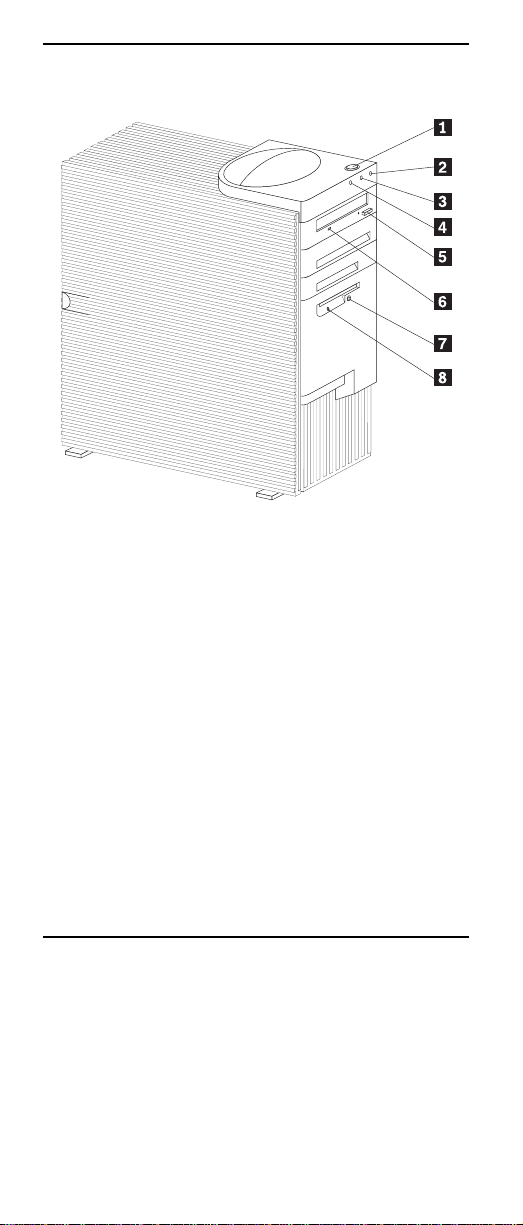
Server controls and indicators
7Socket7Socket
7
Socket7Socket
Þ1Ý Power control butt on: Pre ss this button to manually
turn the server on or off.
Þ2Ý Power-on light: This status indicator lights when you
turn on the server.
Þ3Ý Hard disk drive light: When this light is on, it indi-
cates that the hard disk drive is in use.
Þ4Ý LAN activity light: When this light blinks, it indicates
that the integrated Ethernet controller in the server is
transmitting or receiving data.
Þ5Ý CD-ROM drive eject button: Push this button to
release a CD from the drive.
Þ6Ý CD-ROM drive activity light: When this light is on, it
indicates that the CD-ROM drive is in use.
Þ7Ý Diskette eject button: Push this button to release a
diskette from the drive.
Þ8Ý Diskette-drive activity light: When this light is on, it
indica tes that the diskette drive is in use.
Start the server
After you plug the power cord of the server into the power
supply and a n e l ectr i cal out l et, th e serv er c an star t in s ev er al
ways:
• You can press the Power control button on the front of
the server to start the server.
• If the server is turned on and a power failure occurs,
the server will start automatically when power is
restored.
6 Ne tfinity 3500-M20 – Type 86 57 Models 21Y, 22Y, 3 1Y, 32Y,
Page 16

CAUTION:
The power control button on the device and/or the
power supply do not turn off the electrical current supplied to the device. The device also might have more
than one power cord. T o remove all electrical current
from the device, ensure that all power cords are disconnected from the power source.
2
1
You can turn off the server in the following ways:
• Press the Power control button on the top of the server.
This starts an orde rly shutdown of the operating system, if this feature is supported by the operating system, and places the server in stan dby mode.
Note: After turning off the server, wai t at least 5 sec -
onds before you press the Power control button
to power the server on again.
• Press and hold the Power control button for more than
4 second s to cause an immediate shutdown of the
server and place the server in standby mode. You can
use this feature if the operat ing system ceases to function.
• Disconnect the server power cords from the electrical
outlets to shut off all power to the server.
Note: Wait about 15 seconds after di sconnectin g the
power cords for the system to stop running.
General information 7
Page 17

8 Ne tfinity 3500-M20 – Type 86 57 Models 21Y, 22Y, 3 1Y, 32Y,
Page 18

Diagnostics
This section provides basic troubleshooting information to
help you resolve some c ommon problems that might occur
with the server.
If you ca nnot locate and correct the problem using the information in this section, refer to “Symptom-to-FRU index” on
page 129 for more information.
Diagnostic tools overview
The following tools are available to help you identify and
resolve hardware-related problems:
• POST beep codes, error messages , and error logs
The power-on self-test (POST) generates beep codes
and mess ag es to i nd ic at e suc ces sf ul t est com pl eti on or
the detection of a problem. See “POST” for more information.
• Diagnostic programs and error messages
The server diagnostic programs are stored in upgrad-
able read-only memory (ROM) on th e system board.
These pr ograms are the primary method of testing the
major components of the server. See “Diagnostic programs and error messages” on page 10 for more information.
POST
When you turn on the se rver, it performs a series of tests to
check th e operation of server components and some of the
options installed in the server. This series of tests is called
the power-on self-test or POST.
If POST finishes without detecting any problems, a single
beep sounds and the first screen of the operating system or
application program appears.
If POST detects a problem, more than one beep sounds and
an error mess ag e ap pe ars on th e sc ree n. Se e “P OS T bee p
codes” and “POST error messages” on page 10 for more
information.
Notes:
1. If you have a power-on password set, you must type
the password and press Enter, when prompted, before
POST will continue.
2. A single problem might cause several error messages. When this occurs, work to cor rect the cause of
the first error message. After you correct the cause of
the fi rst error message, the other error messages usually will not occur the next time you run the test .
POST beep codes
POST gene rates beep code s to indicate successful compl etion or the detection of a problem.
9
Page 19

• One beep indicates the successful completion of
POST .
• More than one beep in dicates that POST detected a
problem. For more information, see “Beep symptoms”
on page 129.
POST error messages
POST error messages occur during startup when POST
finds a pro bl em wi t h t he ha rd war e or de t ec ts a ch an ge in th e
hardware configur ation. For a list of POST er rors, see
“POST error codes” on page 141.
Error logs
The POST error log contains the three most recent error
codes and messages that the system generated during
POST.
To view th e contents of the error log, start the Configuration/Setup Utility program (see “Starting the Configuration/Setup Utility program” on page 33); then, select Error
Logs from the main menu.
Diagnostic programs and error messages
The server diagnostic programs are stored in upgradable
read-only memory (ROM) on the system board. These programs are the primary method of testing the major components of the server.
Diagnostic error messages indicate that a problem exists;
they are not intended to be us ed to identify a failing part.
Troubleshooting and servicing of complex problems that are
indica ted b y e rro r mes sages sh oul d be p erf orm ed by t rai ne d
servic e personnel.
Sometimes the first error to occur causes additional errors.
In this case, the server displays more than one error message. Always follow the suggested action instructions for
the
first
error message that appears.
The following sections contai n the error codes that might
appear in the detailed test log and summary log when running the diagnostic programs.
The error code format is as follows:
fff-ttt-iii-date-cc-text message
where:
fff is the three-digit function code that indicates
ttt is the three-digit failure code that indicates
iii is the three-digit device ID.
the fun ction being tested when the error
occurred. For example, function code 089 is
for the microprocessor.
the exact test failure that was encountered.
10 Netfini ty 3500 -M2 0 – Type 8657 Mod els 21Y, 22Y, 31Y, 32Y,
Page 20

date is the date that the diagnostic test was run
cc is the check digit t hat is used to verify the
text message is the diagnostic message that indicate s the
and the error recorded.
validity of the information.
reason for the pro blem.
Text messages
The diagnostic text message format is as follows:
Function Name: Result (test specific string)
where:
Function Name is the name of the function being tested
Result can be one of the following:
when the error occurred. This corresponds
to the function code (fff) given in the previous
list.
Passed This result occurs when the
diagno stic test com pletes
without any errors.
Failed This result occurs when the
diagnostic test discovers an
error.
User Aborte d This result occurs when you
stop the diagnostic test
before it is complete.
Not Applicable This result occur s when you
specify a diagnost ic test for a
device that is not present.
Aborted This result occurs when the
test could not proceed
because of the system configuration.
Warning This result occurs when a
Test Specific String This is addi t iona l i nf orma t io n t hat y ou
can use t o analyze the problem.
possible problem is reported
during the diagnostic test,
such as whe n a de vice th at is
to be tested is not installed.
Starting the diagnostic programs
You can press F1 while running the diagnostic programs to
obtain Help information. Y ou also can press F1 from within a
help screen to obtain online documentation from which you
can sele ct different categori es. To exit Help and return to
where you left off, press Esc.
To start the diagnost ic programs:
1. Turn on the server and watch the screen.
2. When the message F2 for Diagnostics appears,
press F2.
3. Type in the appropriate password; then, press Enter.
Diagnostics 11
Page 21

4. Select either Extended or Basic from the top of the
screen.
5. When the Diagnostic Programs screen appears, select
the t est you w ant to run from the list that appears; then,
follow the instructions on the screen.
Notes:
a. If the server stops during testing and you cannot
continue, restart the server and try runnin g the
diagnostic programs again.
b. The keyboard and mouse (pointing device) tests
assume that a keyboard and mouse are attached
to the server.
c. If you run the diagnostic programs with no mouse
attached to the server, you will not be able to navigate between test categories using the Next Cat
and Prev Cat buttons. All other functions provided by mouse-sel ectable buttons are also available usi ng the funct ion keys.
d. You can test the USB keyboard by using the regu-
lar keyboard test. The regular mouse test can test
a USB mouse. Also, you can run the USB hub test
only if there are no USB devices attached.
e. You can view se r v er co nfiguration in f ormation
(such as system configuration, memory contents,
interrupt request (IRQ) use, direct memory access
(DMA) use, device drivers, and so on) by selecting
Hardware Info from the top of the screen.
When the tests have completed, you can view the Test Log
by sele ct ing Utility from the top of the screen.
If the hardware checks out OK but the problem persists during normal server operations, a software error might be the
cause. If you suspect a software problem, refer to the information that comes wi th the software package.
Viewing the test log
The test log will not contain any information until after the
diagnostic program has run.
Note: If you already are running the diagnostic programs,
begin with step 3.
T o view the test log:
1. Turn on the server and watch the screen.
If th e server i s on, shut down the operating system and
restart the server.
2. When the message F2 for Diagnostics appears,
press F2.
If a power-on password is set, the server prompts you
for it. Type in the appropriate password; then, press
Enter.
3. When the Diagnostic Programs screen appears, select
Utility from the top of the screen.
4. Select View Test Log from the list that appears; then,
follow the instructions on the screen.
12 Netfini ty 3500 -M2 0 – Type 8657 Mod els 21Y, 22Y, 31Y, 32Y,
Page 22

The syst em main ta in s t he t es t- log da ta whi l e t he se rv er
is powered on. When you turn off the power to the
server, the test log is cleared.
Diagnostic error message tables
For des criptions of the error m essages that might appear
when you run the diagnostic programs, see “Diagnostic error
codes” on page 133. If diagnostic error messages appear
that are not listed in those tables, make sure that the server
has the latest level s of BIOS, Adva nced System Management Processor, ServeRAID, and diagnostics microc ode
installed.
Power checkout
Power problems can be difficult to troubleshoot. For
instance, a short circuit can exist anywhere on any of the
power distribution busses. Usu ally a short circuit will cause
the power subsystem to shut down because of an overcurrent condition.
A general procedure for trou bleshootin g po w er problems is
as follows:
1. Power off the system and disconnect the AC cord(s).
2. Check for loose cables in the power subsystem. Also
check for short circuits, for instance if there is a loose
screw causing a short circuit on a circuit board.
3. Remove adapters and disconnect the cables and
power connectors to all internal and external devices
until sy s tem is at minimum configu r ati on requ ir e d for
power on (see "Minimum operating requirements" on
page 148).
4. Reconnect the AC cord and power on the system. If
the system powers up successfully, replace adapters
and devices one at a time until the problem is isolated.
If system does not power up from minimal configuration, replace FRU s of minimal configuration one at a
time unt il the problem is isolated.
T o use this method it is important to know the minimum configuration required for a system to power up (see page 148).
Recovering BIOS
If the BIOS code in the server has become corrupted, such
as from a power failure during a flash update, you can
recover the BIOS using the Fla s h ROM Page-Swap Jumper
(J38) and a BIOS flash diskette .
Note: You can obtain a BIOS flash diskette from one of the
follo wing sources:
• Use the ServerGuide program to make a BIOS
flash diskette.
• Download a BIOS flash diskette from the World
Wide Web. Go to http://www.pc.ibm.com/support/, select IBM Server Support, and make the
selections for the server.
Diagnostics 13
Page 23

The flash memory of the server consists of a primary page
and a backup page. The J38 jumper controls which page is
used to start the server. If the BIOS in the primary page is
corrupted, you can use the backup page to start the server;
then bo ot th e B I OS Fl ash D isk ett e t o res to r e th e BI OS to the
prima r y pa ge .
To recover the BIOS:
1. Turn off the serv er and peripheral devices and discon nect all external cables and power cords; then, remove
the cover.
2. Locate jumper J38 on the processor board (see “Sys-
tem board switches and jumpers” on page 42). The
jumper consists of three pins, two of which are cove red
by a jumper.
3. Move the J38 jumper from its current location to connect the center pin and the pin on the opposite end of
the co nnector block, as shown in the following diagram:
4. Insert the BIOS flash diskette into the diskette drive.
5. Restart the server.
6. The system begins the power-on self-test (POST).
Select 1 – Update POST/BIOS from the menu that contains various flash (update) options.
7. When you are asked whether you want to save the current code to a diskette, type N.
8. You will be asked to choose which language you wish
to use. Select your language (0-7) and press Enter to
acce pt yo ur choice.
9. Do not reboot the system at this time.
10. Remove the BIOS Flash Diskette from the diskette
drive.
11. Power-off the server.
12. Move jumper J38 back to its original setting to return to
normal startup mode.
13. Restart the server. The system should start up normally.
Replacing the battery
IBM has designed this product with your safety in mind. The
lithium battery must be handled correctly to avoid possible
14 Netfini ty 3500 -M2 0 – Type 8657 Mod els 21Y, 22Y, 31Y, 32Y,
Page 24

danger. If you replace the battery, you must adhere to the
follo wing instructions.
CAUTION:
When replacing the battery, use only IBM Part Number
33F8354 or an equivalent type battery recommended by
the manufacturer. If your system has a module containing a lithium battery, replace it only with the same module type made by th e same manufacturer. The battery
contains lithium and can explode if not properly used,
handled, or disposed of.
Do not:
• Throw or immerse into water
• Heat to more than 100°C (212°F)
• Repair or disassemble
Dispose of the battery as required by local ordinances
or regulations.
Note: In the U.S., call 1-800-IBM-4333 for information about
battery disposal.
If you replace the original lithium battery with a heavy-metal
battery or a battery with heavy-metal components, be aware
of the following environmental consideration. Batteries and
accumulators that contain heavy metals must not be disposed of with normal domestic waste. They will be taken
back free of charge by the manufacturer , distribu tor, or representative, to be recycled or disposed of in a proper manner.
Note: After you replace the batter y, you must reconfigure
the server and reset the system date and time.
To replace the battery:
1. Read the information in “ Before you begin” on page 43.
2. Follow a ny spec ial hand lin g and in stall atio n instr uctio ns
supplied with the battery.
3. Turn of f t he server an d al l att ach ed dev ic es an d di sco nnect all external cables and power cords (see “Safety
information” on page 155); then remove the top cover.
4. Locate the battery on the system board (see “System
board component locations” on page 39).
5. Remove ad apters as necessary so you can access the
batte ry. (See “Working with adapters” on page 45.)
6. Remove the battery:
a. Use one finger to lift the battery clip over the bat-
tery.
b. Use one fi nger to slightly slide the battery toward
the rear of the server. The spring mechanism
behind the battery will push it ou t toward you as
you slide it forward.
c. Use your thumb and index finger to pull the bat-
tery from under the battery clip.
d. Ensure that the battery clip is touching the base of
the battery socket by pressing ge ntly on the cl ip.
Diagnostics 15
Page 25

7. Insert the new battery:
a. Tilt the battery so that you can insert it into the
front of the socket, under the battery clip.
b. As you slide it under the battery clip, press the
battery down into t he socket.
8. Reinsta ll any adapters that you removed.
9. Reinstall the top cover.
Note: You must wait approximately 20 seconds after
you plug the power cord of the server into an
electrical outlet before the power control button
becom e s ac t i ve .
10. Start the Configuration/Setup Utility program and set
configuration parameters as needed. Refer to “Using
the Configuration/Setup Utility program” on page 33.
Temperature checkout
Proper cooling of the system is important for proper operation and system reliability. For a typical Netfinity server, you
should make sure:
• Each of t h e d riv e b ay s h as ei ther a d rive o r a f i ll er pan el
install ed
• The top cover is in place during normal operation
• There is at least 50 mm (2 inches) of ventilated space
at the sides of the server and 100 mm (4 inches ) at the
rear of the server
• The top c ove r i s r em ove d fo r no long er th an 30 mi nute s
while the server is operating
• Cables for optional adapters are routed according to
the instructions provided with the ada pters (ensure that
cables a re not restr icting air flow)
• The fans are operating correctly and the air flow is
good
• A failed fan is replaced within 1 hour.
16 Netfini ty 3500 -M2 0 – Type 8657 Mod els 21Y, 22Y, 31Y, 32Y,
Page 26

In addition, ensure that the environmental specifications for
the system are met. See “Feature s an d sp ec ifications” on
page 3.
Diagnosing errors
To find solutions to problems that have definite symptoms,
see “Error symptoms” on page 138.
If you cannot find the problem there, go to “Starting the diagnostic programs” on page 11 to test the server.
If you have j ust ad ded ne w softw ar e or a ne w optio n an d the
server is not working, do the follow ing before using the error
symptoms table:
• Remove the software or device that you just added.
• Run the diagnostic tests to determine if the server is
runnin g correctly.
• Reins tall the new software or new device.
Troubleshooting the Ethernet controller
This section provides troubleshooting information for problems tha t might occur with the 10/100 Mbps Ethernet controller.
Network connection problems
If the Ethernet controller cannot connect to the net work,
check th e following:
• Make sur e that the cable is instal led correctly.
The network cable must be securely attached at all
connections. If the cable is attached but the problem
persists, try a different cable.
If you set the Ethernet controller to operate at 100
Mbps, you must use Category 5 cabling.
If you dir ec tl y con nect t wo w orks ta t ions ( wit ho ut a hu b) ,
or if you are not usin g a hub with X por ts, use a crossover cable.
Note: To determine whether a hub has an X port,
check th e port label. If the label contains an
the hub ha s an X por t.
• Determine if the hub supports auto-negotiation. If not,
try configuring the integrated Ethernet controller manually to match the speed and duplex mode of the hub.
• Check the Ethernet controller lights on the operator
information panel.
These lights indicate whether a problem exists with the
connector, cable, or hub.
— The Ethernet Link Status light illuminates when
the Ethe r net co nt ro ll er rec ei ve s a L INK pu ls e fr om
the hub. If the light is off, there might be a defective co nnector or cable, or a problem with the hub.
— The Ethernet Transmit/Receive Activity light illumi-
nates when the Ethernet controller sends or
receives data over the Ethernet Network. If the
Ethernet Transmit/Receive Activity light is off,
Diagnostics 17
X
,
Page 27

make sure that the hub and network are operating
and that the correct device drivers are loaded.
— The Ethernet Speed 100 Mbps light illuminates
when the Ethernet controller LAN speed is
100 Mbps.
• Make sure that you are using the correct device drivers,
suppli ed with the ser v er.
• Check for operating sys tem-specific causes for the
problem.
• Make sur e that the device drivers on the client and
server ar e using the same protocol.
• Test the Ethernet controller.
How you test the Ethernet controller depends on which
operating system you are using (see the Ethernet controller device driver README file).
Ethernet controller trouble s ho ot in g chart
You can use the following troubleshooting chart to find solutions to 10/100 Mbps Ethernet controller problems that have
definite symptoms.
T able 1. Ethernet trou bleshootin g chart
Ethernet
controller
problem
The serv er
stops
runnin g
when loading
device
drivers.
Suggested Action
The PCI BIOS interrupt settings are
incorrect.
Check the following:
• Determin e if the inte r ru pt (IR Q )
setting assigned to the Ethernet
controller is also assigned to another
device in the Configuration/Setup
Utility program.
Although interrupt sharing is allowed
for PCI devices, some devices do not
function well when they share an
interrupt with a dissimilar PCI device.
Try ch an ging t he I RQ assi gn ed to t he
Ethernet controller or the ot her
device. For exam ple, for NetWare
Versions 3 and 4 it is recommended
that disk controllers not share
interrupts with LAN controllers.
• Make sure that you are using the
most recent device driver available
from the World Wide Web.
• Run the network diagnostic program.
18 Netfini ty 3500 -M2 0 – Type 8657 Mod els 21Y, 22Y, 31Y, 32Y,
Page 28

T able 1. Ethernet trou bleshootin g chart
Ethernet
controller
problem
Ethern et Link
Status lig ht
does not
light.
The Ethernet
Transmit/
Receive
Activity lig h t
does not
light.
Data is
incorrect or
sporadic.
Suggested Action
Check the following:
• Make sure that the hub is turned on.
• Check all connections at the Ethernet
controller and the hub.
• Check the cable. A crossover cable
is required unless the hub has an
designation.
• Use another po rt on the hub.
• If the hub does not support autonegotiation, manually configure the
Ethernet controller to match the hub.
• If you manually configured the duplex
mode, make sure that you also
manually configure the speed.
• Run diagnostics on the LEDs.
Check the following:
Note: The Ethernet Transmit/Receive
Activity LED illuminates only when
data is sent to or by this Ethernet
controller.
• Make sure that you have loaded the
network device drivers.
• The network might be idle. Try
sendin g da ta from this workstat ion.
• Run diagnostics on the LEDs.
• The function of this LED can be
changed by device driver load
parameters. If necessary , remove
any LED parameter settings when
you load the device drivers.
Check the following:
• Make sure that you are using
Categor y 5 cab lin g w he n op erating
the server at 100 Mbps.
• Make sure that the cables do not run
close to noise-inducing sources like
fluo rescent lights.
X
Diagnostics 19
Page 29

T able 1. Ethernet trou bleshootin g chart
Ethernet
controller
problem
The Ethernet
controller
stopped
workin g
when
another
adapter was
added to the
server.
The Ethernet
controller
stopped
workin g
without
apparent
cause.
Suggested Action
Check the following:
• Make sure that the cable is
connected to the Ethernet controller.
• Make sure that the PCI system BIOS
is current.
• Res eat the adapter.
• Determin e if the inte r ru pt (IR Q )
setting assigned to the Ethernet
adapter is also assigned to another
device in the Configuration/Setup
Utility program.
Although interrupt sharing is allowed
for PCI devices, some devices do not
function well when they share an
interrupt with a dissimilar PCI device.
Try ch an ging t he I RQ assi gn ed to t he
Ethernet adapter or the other device.
Check the following:
• Run diagnostics for the Ethernet
controller.
• T ry a different connector on the hub.
• Reinstall the device drivers. Refer to
the operating-system documentation
and to the ServerGuide information.
Ethernet controller messages
The integrated Ethernet controller might display messages
from the following device drivers:
• Novell™ NetWare™ or IntraNetWare Server ODI
• NDIS Adapter for level 2.01 (OS/2)
• NDIS Adapter for level 4.0 (Windows NT)
• SCO ™ UNIX LLI
Novell NetWare or IntraNetWare server ODI driver messages
This se ctio n p r ov id es ex pl an at io ns of t he err o r mes sa ge s f or
the Novell NetWare or IntraN etWare server ODI dr iver, and
suggested actions to resolve each problem.
20 Netfini ty 3500 -M2 0 – Type 8657 Mod els 21Y, 22Y, 31Y, 32Y,
Page 30

Table 2. Novell NetWare or IntraNetWare ODI driver
messages for the Ethernet controller
PCNTNWNW-026
PCNTNWNW-054
PCNTNWNW-058
PCNTNWNW-066
The MSM is unable to parse a required
custom keyword.
Explanation: The us er entered an
incorrect parameter keyword.
Action: Reload the driver using the
corre ct keyword.
The adapter did not respond to the
initialization command.
Explanation: The adapter did not
respond when the d river tried to initialize
it.
Action: Verify that the Ethernet controller
is enabled. If the Ethernet controller is
enabled, go to “Starting the diagnostic
programs” on page 11 to r un the
diagnostic programs.
The adapter did not respond to the
initialization command.
Explanation: The interrupt request (IRQ)
setting might not be valid or the EEPROM
information might be incorrect.
Action: Make sure the IRQ settings are
correct in the Configuration/Setup Utility
program. for information on setting the
interrupt requests. If the IRQ settings are
correct, go to “Starting the diagnostic
programs” on page 11 to r un the
diagnostic programs.
The cable might be disconnected from
the adapter.
PCNTNWNW-071
Explanation: The cable might be
disconnected from the server Ethernet
port.
Action: V erify that a cable is connected
to the Ethernet port.
The matching virtual adapter could not
be found.
Explanation: You tried to load another
instance of the driver with a different I/O
address. This new adapter could not be
found.
Action: V erify that you installed an IBM
Netfinity 10/100 Fault Tolerant Adapter
and make sure that the adapter is seated
correctly. If the adapter is seated
correctly, go to “Starting the diagnostic
programs” on page 11 to r un the
diagnostic programs.
Diagnostics 21
Page 31

Table 2. Novell NetWare or IntraNetWare ODI driver
messages for the Ethernet controller
PCNTNWNW-072
PCNTNWNW-073
PCNTNWNW-074
PCNTNWNW-075
A resource tag is unavailable.
Explanation: The driver tried to allocate
some resources that were not available.
Action: Add more memory, or free some
memory resources in the server. Then,
restart the server.
Unable to allocate memory
Explanation: The driver failed to allocate
the memory needed for normal operation.
Action: Add more memory, or free some
memory resources in the server. Then,
restart the server.
The hardware interrupt cannot be set.
Explanation: An attempt was made to
init ialize a given hardware interrupt. The
attempt was not successful.
Action: Verify that the Ethernet controller
is enabled. If the Ethernet controller is
enabled, go to “Starting the diagnostic
programs” on page 11 to r un the
diagnostic programs. If you have an
Ethernet adapter installed, make sure that
the ad apter does not share an IRQ with
any other dev ic e .
The Multiple Link Interface Driver
(MLID) cannot be registered with the
Link Support Layer (LSL).
Explanation: An error occurred while the
driv er was trying to register with the LSL.
Action: Check the version of the
NetWare or IntraNetWare Operating
System. Make sure that this driver is
correct for the version of Net Ware or
IntraNetWar e that you are using. Restart
the server.
PCNTNWNW-079
The Multiple Link Interface Driver
(MLID) did not initialize MSMTx Free
Count.
Explanation: The MSMTx Free Count is
not initialized correctly.
Action: Restart the server. If the problem
pers ists, go to “Starting the diagnostic
programs” on page 11 to r un the
diagnostic programs.
22 Netfini ty 3500 -M2 0 – Type 8657 Mod els 21Y, 22Y, 31Y, 32Y,
Page 32

Table 2. Novell NetWare or IntraNetWare ODI driver
messages for the Ethernet controller
PCNTNWNW-086
PCNTNWNW-087
PCNTNWNW-091
PCNTNWNW-126
The driver parameter block is too
small.
Explanation: The driver parameter block
is too small.
Action: Restart the server. If the
problem persists, go to “Starting the
diagnostic programs” on page 11 to run
the diagnostic programs.
The media parameter block is too
small.
Explanation: The driver me di a
parameter block is too small.
Action: Restart the server. If the
problem persists, go to “Starting the
diagnostic programs” on page 11 to run
the diagnostic programs.
The hardware configuration conflicts.
Explanation: You tried to load a new
frame type for the existing controller. The
hardware assumptions made in doing so
are incorrect. This error can also occur if
you try to specify a mode (such as,
redundancy) that conflicts with another
specified mode.
Action: Make sure that the hardware
configuration matches the software
settings.
The group bit in the node address
override was cleared.
Explanation: The IEEE address has a
group bit that indicates that an address
belongs to a group of stations. This bit is
used only as a destination address; it
cannot be used as a source address. You
tried to enter a source address with this bit
set. The dr iv er c l ear e d t he gr o up bi t of t he
source address.
Action: None necessary, message is for
informa tio n only.
Diagnostics 23
Page 33

Table 2. Novell NetWare or IntraNetWare ODI driver
messages for the Ethernet controller
PCNTNWNW-127
PCNTNWNW-164
PCNTNWNW-165
PCNTNWNW-167
PCNTNWNW-180
The local bit in the node address
override was set.
Explanation: The local bit in the IEEE
address format indicates that the
addresses are bei ng managed locally. If
you use the nod e ad dress override
capabilities of this driver to enter a new
address, the local bit must be se t. You
entered an address without the local bit
set. The driver has set the local bit.
Action: None necessary, message is for
informa tio n only.
The device was not found.
Explanation: The driver cannot find an
Ethernet controller in the server.
Action: Verify that the Ethernet controller
is enabled. If the Ethernet controller is
enabled, go to “Starting the diagnostic
programs” on page 11 to r un the
diagnostic programs.
The device was not found at
IOADDRESS.
Explanation: The Ethernet controller
cannot be found at the I/O address
specified.
Action: The Ethernet controller does not
require a parameter for the I/O address.
Remove the I/O address parameter.
PCI scan specified, device not found.
Explanation: The driver cannot locate
the Ethernet controller on the PCI bus.
Action: Verify that the Ethernet controller
is enabled. If the problem persists, go to
“Starting the diagnostic programs” on
page 11 to run the diagnostic programs.
The DMA parameter is not necessary
for PCI device.
Explanation: The Ethernet controller
does not require a DMA setting.
Action: None necessary, message is for
informa tio n only.
Network driver interface specification 2.01 (OS/2) driver messages
This se ctio n p r ov id es ex pl an at io ns of t he err o r mes sa ge s f or
the NDIS 2.01 (OS/2) drivers, and suggested actions to
resolve each problem.
24 Netfini ty 3500 -M2 0 – Type 8657 Mod els 21Y, 22Y, 31Y, 32Y,
Page 34

T able 3. N DIS 2.01 (OS/2) driver messages for the Ethernet
controller
PCNTND-1 Unable to open the Protocol Manager.
Explanation: The NDIS stack is not
configured correctly.
Action: Check and co r rec t the
configu ration.
PCNTND-6 Out of memory while allocating
buffers.
Explanation: The driver could not
allocate the requested buffers.
Action: Check t h e s yste m c onf i gur at ion.
Edit the PROTOCOL.INI file to reduce the
number of Txbuffers and Rxbuffers
specified for the driver.
PCNTND-7 A Protocol Manager device error
occurred.
Explanation: The NDIS stack is not
configured correctly.
Action: Check and co r rec t the
configu ration.
PCNTND-8 Bad status for the Protocol Manager.
Explanation: The NDIS stack is not
configured correctly in the
PROTOCOL.INI file.
Action: Check and co r rec t the
configu ration.
PCNTND-9 Cannot find the PROTOCOL.INI entry.
Explanation: The NDIS stack is not
configured correctly in the
PROTOCOL.INI file.
Action: Check and co r rec t the
configu ration.
PCNTND-10 The Protocol Manager Input Output
Control (IOCTL) failed.
Explanation: The NDIS stack is not
configured correctly in the
PROTOCOL.INI file.
Action: Check and co r rec t the
configu ration.
PCNTND-11 Protocol Manager registration failed.
Explanation: The NDIS stack is not
configured correctly.
Action: Check and co r rec t the
configu ration.
Diagnostics 25
Page 35

T able 3. N DIS 2.01 (OS/2) driver messages for the Ethernet
controller
PCNTND-15 De vic e not found.
Explanation: The driver cannot find an
Ethernet controller in t he server.
Action: Verify that the Ethernet controller
is enabled. If the Ethernet controller is
enabled, go to “Starting the diagnostic
programs” on page 11 to run the
diagnostic programs.
PCNTND-16 PCI scan specified, device not found.
Explanation: The driver cannot locate
the Ethernet controller on the PCI bus.
Action: Verify that the Ethernet controller
is enabled. If the Ethernet controller is
enabled, go to “Starting the diagnostic
programs” on page 11 to run the
diagnostic programs.
PCNTND-21 The adapter failed the checksum test.
Explanation: The driver cannot find an
Ethernet controller.
Action: Verify that the Ethernet controller
is enabled. If the Ethernet controller is
enabled, go to “Starting the diagnostic
programs” on page 11 to run the
diagnostic programs.
PCNTND-23 WARNING: PCNET IRQ found =
xx
Explanation: The interrupt request (IRQ)
setting (
xx
does not match the hardware IRQ setting.
Action: Remove the IRQ setting from the
PROTOCOL.INI file or change the IRQ
setting in the PROTOCOL.INI file to
match the IRQ setting shown in the PCI
Slot/Device Information selection of the
Advanced Setup menu in the
Configuration/Setup Utility program.
PCNTND-24 WARNING: PCNET IRQ does not
match PROTOCOL.INI.
Explanation: The interrupt request (IRQ)
setting in the PROTOCOL.INI file does
not match the hardware IRQ setting.
Action: Remove the IRQ setting from the
PROTOCOL.INI file or change the IRQ
setting in the PROTOCOL.INI file to
match the IRQ setting shown in the PCI
Slot/Device Information selection of the
Advanced Setup menu in the
Configuration/Setup Utility program.
) in the PROTOCOL.INI file
26 Netfini ty 3500 -M2 0 – Type 8657 Mod els 21Y, 22Y, 31Y, 32Y,
Page 36

T able 3. N DIS 2.01 (OS/2) driver messages for the Ethernet
controller
PCNTND-25 PCI scan specified, PCI bus not found!
Explanation: The driver cannot locate
the PCI bus.
Action: Run the diagnostic programs.
PCNTND-29 WARNING: DMA number is not
PCNTND-33 PCNET device with specified IOBASE
nece ssary for PCI device.
Explanation: The Ethernet controller
does not require a DMA setting.
Action: Remove the DMA setting in the
PROTOCOL.INI file.
is already in use.
Explanation: The specified I/O address
number is already in use by another
Ethernet controller or device.
Action: Remove the I/O address setting
in the PROTOCOL.INI file.
NDIS 4.0 (Windows NT) driver messages
This section contains the erro r messages for the NDIS 4.0
drive rs. The expla nation and recommended action are
includ ed with each message.
T able 4. NDIS (Windows NT) driver messages for th e
Ethernet controller
PermaNet™
Server:
PermaNet
Server:
No Secondary Adapter Found.
Grouping Mode is disabled.
Explanation: The f ai l ove r op t io n re qui res
an adapter that is compatible with the
device driver of the Ethernet controller on
the system board. No such adapter was
found .
Action: Make sure th e correct adapter is
installed.
Problem Occurs on the Primary
Adapter. Switching over to the
Secondary Adapter.
Explanation: The system detected a
problem with the primary Ethernet
connection and has transferred all network
traf fic to the seco ndary Ether net contro ller.
Action: identify the cause of the failure
on the primary Ethernet connection.
Restoring the operational state of the
primary connection will cause the network
traffic to automatically transfer to the
primary Ethernet controller.
Diagnostics 27
Page 37

T able 4. NDIS (Windows NT) driver messages for th e
Ethernet controller
PermaNet
Server:
Switching back to Primary Adapter.
Explanation: The primary Ethern et
connection is now operating correctly.
Network traffic will automatically transfer
to the primary Ethernet controller.
Action: None needed, message is for
information only.
UNIX messages
This section provides descriptions of the Ethernet error messages for the SCO UNIX LLI driver, and suggested actions
to resolve each problem.
T able 5. UNIX LLI driver messages for t he Ethernet
controller
pnt0-2 PCI search specified, PCI device not found!
Explanation: The driver cannot locate the
Ethernet controller on the P CI bus.
Action:
• Run the NETCONFIG program to search
for another Ethernet controller
• Verify that the Ethernet controller is
enabled. If the Ethernet controller is
enabled, run the diagnostic programs.
pnt0-6 Cannot allocate memory for the adapter
during an interrupt. Please check the
Streams parameters.
Explanation: On a SunSoft Solaris system,
this mes sage indi cate s that the system is ou t of
Streams memory blocks.
Action: Use the CRASH utility to increase the
number of Strea ms memory bl ocks. Modify the
interrupt request (IRQ) settings in the
Configuration/Setup Utility program, or run the
NETCONFIG program to match the hardware
settings.
pnt0-7 Cannot allocate memory for the adapter
during reset. Please check the Streams
parameters.
Explanation: The system is out of Streams
memory blocks.
Action: Use the CRASH utility to increase the
number of Streams memory blocks.
28 Netfini ty 3500 -M2 0 – Type 8657 Mod els 21Y, 22Y, 31Y, 32Y,
Page 38

T able 5. UNIX LLI driver messages for t he Ethernet
controller
pnt0-11 Device not found!
Explanation: The driver cannot find an
Ethernet controller.
Action: V erify that the Ethern et controll er is
enabled. If the Ethernet controller is enabled,
run the diagnostic programs.
pnt0-12 Device failed checksum test!
Explanation: The driver cannot find an
Ethernet controller.
Action: V erify that the Ethern et controll er is
enabled. If the Ethernet controller is enabled,
run the diagnostic programs.
pnt0-13 add_intr_handler failed! Interrupts already
enabled.
Explanation: The interrupt request (IRQ) that
was specified, or t he IRQ that was found,
conflicts with other devices in the server.
Action: Modify the hardware settings.
pnt0-14 Cannot locate hardware.
Explanation: The SunSoft Sola ris driver
cannot find any Ethernet controller.
Action: V erify that the Ethern et controll er is
enabled. If the Ethernet controller is enabled,
run the diagnostic programs.
pnt0-15 No more devices to open.
Explanation: The SunSoft Sola ris driver
cannot find any more Ethernet controllers.
Action: Verify that additional IBM Netfinity
10/100 Fault T olerant Adapters are present or
replace the Ethernet adapter that fails to
respond. If the problem persists, run the
diagnostic programs.
pnt0-17 Device fault...Reset initiated!
Explanation: The SunSoft Solaris driver has
been reset due to a device fault.
Action: Verify that additional IBM Netfinity
10/100 Fault T olerant Adapters are present or
replace the Ethernet adapter that fails to
respond. If the problem persists, run the
diagnostic programs.
Diagnostics 29
Page 39

T able 5. UNIX LLI driver messages for t he Ethernet
controller
pnt0-19 IRQ found for PCnet hardware does not
pnt0-20 add_intr_handler failed! Unknown interrupt
pnt0-21 add_intr_handler failed! Out of range
pnt0-22 add_intr_handler failed! Out of range IPL.
match space.c (or pnt.conf)!
Explanation: This is a warning message
referring to the interrupt request (IRQ) that the
SunSoft Solaris driver found in the system.
Action: Ignore this message if you are sure
that t hi s i s wh at you w a nt t o d o. O the r wis e, run
the NETCONFIG program to match the
hardware settings
type.
Explanation: The interrupt request (IRQ) that
was specified, or t he IRQ that was found,
conflicts with other devices in the server.
Action:
• Modify the hardware settings.
• Run the NETCONFIG program to search
for another Ethernet controller.
interrupt number.
Explanation: The interrupt request (IRQ) that
was specified, or t he IRQ that was found,
conflicts with other devices in the server.
Action:
• Modify the hardware settings.
• Run the NETCONFIG program to search
for another Ethernet controller.
Explanation: The interrupt request (IRQ) that
was specified, or t he IRQ that was found,
conflicts with other devices in the server.
Action: Modify the hardware settings. Run
the NETCONFIG program to search for
another Ethernet controller.
pnt0-23 add_intr_handler failed! Vector already
occupied.
Explanation: The interrupt request (IRQ) that
was specified, or t he IRQ that was found,
conflicts with other devices in the server.
Action: Modify the hardware settings.
30 Netfini ty 3500 -M2 0 – Type 8657 Mod els 21Y, 22Y, 31Y, 32Y,
Page 40

T able 5. UNIX LLI driver messages for t he Ethernet
controller
pnt0-24 add_intr_handle r faile d! Vector alrea dy
shared at different IPL.
Explanation: The interrupt request (IRQ) that
was specified, or t he IRQ that was found,
conflicts with other devices in the server.
Action:
• Modify the hardware settings.
• Run the NETCONFIG program to search
for another Ethernet controller.
pnt0-26 The DMA number is not necessary for PCI
device.
Explanation: The IBM Netfinity 10/100 Fault
Tolerant Adapter does not require a DMA
setting.
Action: Edit the SPACE.C file to delete the
DMA parameter.
pnt0-29 The IRQ number is already in use.
Explanation: The specified I/O address is
already in use.
Action: Run the NETCONFIG program to
modify the hardware settings.
pnt0-31 I/O address is not necessary for the PCI
device.
Explanation: The I/O address specified is not
required.
Action: Remove the assigned I/O addre ss
specified for the Ethernet controller.
Diagnostics 31
Page 41

32 Netfini ty 3500 -M2 0 – Type 8657 Mod els 21Y, 22Y, 31Y, 32Y,
Page 42

Configuring the server
The following configuration programs are provided with the
server:
• Config ura tion /Se tup U tili ty
The Configuration/Setup Utility program is part of the
basic i nput/output system (BIOS
the ser v er. You can use this program to configure
serial and parall el port assi gnments, change inter rupt
request (IRQ) settings, change the drive startup
sequence, set the date and time, and set passwords.
See “Using the Configuration/Setup Utility program” for
more information.
• SCSISelect Utility
With the built-in SCSISelect Utility program, you can
configure the devices attached to the integrated SCSI
controller. U s e this program to change default values,
resolv e con figuration con fli cts, and perfo rm a low -l ev el
format on a SCSI hard disk drive. See “Using the
SCSISelect utility program” on page 37 for more information.
• ServerGuide CDs
The ServerGuide CDs include software setup and
installation tools specifically designed for IBM Netfinity
servers. You can use these CDs during the initial
installation of the server to configure the server hardware and simplify the network operating system installation. The ServerGuide CDs also contain a collection
of application programs, which you can install after the
server is up and runn ing.
• ServeRAID programs
The ServeRAID programs come with the optional Serv-
eRAID adapters and with server models that have a
ServeRAID adapter preinstalled. If a ServeRAID
adapter has been installed in the server, you must use
the ServeRAID configuration program to define and
configure the disk-array subsystem before you install
the ope rating system.
) code that comes with
Using the Configuration/Setup Utility program
This section provides the instructions needed to start the
Configuration/Setup Utility program and descriptions of the
menu choices available.
Starting the Configuration/Setup Utility program
T o start the Configuration/Setup Utility program:
1. Turn on the server and watch the monitor screen.
2. When the message Press F1 for Configura-
tion/Setup appears, press F1.
3. Follow the instructions that appear on the screen.
33
Page 43

Choices available from the Configuration/Setup main menu
From the Con fi guration/Se tu p U til ity mai n me nu , you can
select s ettings th at you want to change. The Configuration/Setup Utility main menu is similar to the following:
IBM Netfinity Setup - © IBM Corporation 1998
Configuration/Setup Utility
•
System Summary
•
System Information
•
Devices and I/O Ports
•
Date and Time
•
System Security
•
Start Options
•
Advanced Setup
•
Error Logs
Save Settings
Restore Settings
Load Default Settings
Exit Setup
<F1> Help < > < > Move
<Esc> Exit <Enter> Select
↑↓
Notes:
1. You can pre ss F 1 to di sp la y H el p info r m at io n for a
selected menu item.
2. The choices on some menus might differ slightly,
depending on the BIOS version in the server.
Descriptions of the choices available from the main menu
are as follows:
• System Summary
Select this choice to display configuration information.
This includes the type and speed of the microprocessors and the amount of memory ins talled.
Changes that you make to configuration settings
appear on this summary screen. You cannot edit th e
fields.
This choice appears on both the full and limited Configuration/Setup Utility menus.
• System Information
Select this choice to display information about the
server. Changes that you make on other menus might
appear on this summar y screen. You cannot edit any
fields. The System Information choice appears only on
the full Configuration/Setup Utility main menu.
— Product Data
Select this choice to view system information,
such as the machine type and model, the server
serial number, and the revision level or issue date
of the BIOS stored in the flash electronically erasable programmable ROM (EEPROM).
• Devices and I/O Ports
34 Netfini ty 3500 -M2 0 – Type 8657 Mod els 21Y, 22Y, 31Y, 32Y,
Page 44

Select this choice to view or change the assignments
for dev ic es an d in put/ o ut pu t po r ts. Th is choi ce a pp ea rs
only on the full Con figuration/Setup Ut ility main menu.
• Date and Time
Select this choice to set the system date and time.
The system time is in a 24-hour format:
hour:minute:second.
• System Security
Select this choice to set a power-on password. See
“Using passwords” on page 36 for more information.
• Start Options
Select this choice to view or change the start options.
Start options take effect when you start the server.
You can select keyboard operating characteristics,
such as the keyboard speed. You also can specify
whether the keyboard number lock starts on or off. You
also can enable the server to run without a diskette
drive , monitor, or keyboa rd.
The serv er uses a startup sequence to determine the
device from which the operating system loads. For
example, you can defin e a sta rtup sequence tha t
checks fo r a starta ble di sket te in the disket te dri ve, th en
checks the hard disk drive in bay 1, and then checks a
network adapter.
You also can select which PCI Small Computer System
Interface (SCSI) adapter is given boot precedence.
The first drive th at is attached to the selected adapter
will be assigned dr ive number 80H and the operating
system will start from that drive. The default for boot
preced ence is Disab led. The range of choices
depends upon the number of PCI SCSI adapters
installed in the server.
You can enable a virus-detection test that checks for
changes in the master boot record at startup.
• Adva nc ed Setup
Select t his choice to c hange values for advanced hard-
ware features, such as cache control and PCI configuration.
A warn ing message appears above the choices on this
menu to alert you that the system might malfunction if
these options are configured incorrectly. Follow the
instructions on the screen carefully.
— Processor Serial Number Access
Select this choice to identify if the microprocessor
serial number in the microprocessor is readable.
— Core Chipset Control
Select this choice to modify settings that control
features of the core chip set on the system board.
Attention: Do not make changes here unless
directed to do so by an IBM authorized service
representative.
— Cache Control
Configuring the server 35
Page 45

Select this choice to enable or disable the microprocessor cache. In addition, you can define the
microprocessor cache type as write-back (WB) or
write-through (WT). Selecting write-back mode
will provide the maximum system performance.
— PCI Bus Control
Select this choice to assign IRQs and program the
master latency time r.
Note: If a memory error is detected during normal
operations, System Management Interrupt
(SMI) can disable the memory.
— Memory Settings
Select this choice to manually disable or enable a
bank of memory.
If a memo ry error is detected during POST or
memory configuration, the server can automatically disable the failing memory bank and continue operating with reduced memory capacity. If
this occurs, you must manually enable the memory bank after the pr oblem is corrected. Select
Memory Settings from the Advanced Setup
menu, use the arrow keys to highlight the bank
that you want to enable; then, use the arrow keys
to select Enable.
• Error Log
Select this choice to view or clear the error log.
— Select POST Error Log to view the three most
recent error codes a nd messages that the system
generated during POST.
— Select Clear error logs to clear the error logs.
• Save Settings
Select this choice to save the customized settings.
• Restore Settings
Select this choice to delete the changes and restore the
previous settings.
• Load Default Settings
Select this choice to cancel the changes and restore
the factory settings.
• Exit Setup
If you have made any changes, the program will prompt
you to save the changes or exit without saving the
changes.
Using passwords
The System Security choice appears only on the full Con-
figuration/Setup Utility menu. After you select this choice,
you can im plement a power-on passwor d.
Power-on passwor d
After you set a power-on password, you can enable the
unattended-start mode. This locks the keyboard and
mouse, but allows the server to start the operating system.
36 Netfini ty 3500 -M2 0 – Type 8657 Mod els 21Y, 22Y, 31Y, 32Y,
Page 46

The keyb oard and mouse remain locked until you en ter the
correct password.
You can use any combination of up to seven characters (A–
Z, a–z, and 0–9) for the power-on password. Keep a record
of the p assword in a secure place. If you forget the poweron passw ord, you can regain access to the ser v er through
one of the following methods:
• Start the Configu ration Setup Utility p rogram and
change the power-on password.
• Change t he p osi t ion of the pa ss wor d ove r rid e swit ch a s
described in “Setting the password override switch”.
• Remove the battery and then instal l the battery.
Setting the password override switch:
power-on password is set, POST does not complete until
you enter the passw ord. If you forget the power-on password, you can regain access to the server by changing the
positi on of switch 8 on the system board to bypass the
power-on password check. You can then start the Configuration/Setup Utility program and change th e power-on pa ssword. For the location of the password override switch, see
Table 6 on page 43.
When a
Using the SCSISelect utility program
SCSISelect is a built-in, menu-driven configuration utility
program that you can use to:
• View the default SCSI IDs
• Locate and correct configuration conflicts
Note: If t he server ha s a RAID adapter install ed, use the
config uration method supplied with th e RAID adapt er
to view or change SCSI settings for attached devices.
Starting the SCSISelect utility program
T o start the SCSISelect utility program:
1. Turn on the server.
2. When the <<< Press <CTRL><A> for SCSISelect™
Utility! >>> prompt appears, press Ct rl+A.
3. When the Would you like to configure the host
adapter or run the SCSI disk utility? question
appears, make your selection and press Enter.
4. Use the arrow keys to select a choice from the menu.
• Press Esc to return to the previous menu.
• Press the F5 key to switch between color and
monochrome modes (if the monitor permits).
5. Follow the instructions o n the screen to change the settings of the selected items; then, press Enter.
Choices available from the SCSISelect menu
The following choices appear on the SCSISelect Utility
menu:
Configuring the server 37
Page 47

• Configure/View Host Adapter Settings
Select this choice to view or change the SCSI controller
settings. To reset the SCSI controller to its default values, press F6; then , follow the instructions that app ear
on the sc reen.
You can view or change the following controller settings:
— Host Adapter SCSI ID
Select this choice to view the SCSI controller ID,
normally 7.
— SCSI Parity Checking
Select this choice to view the assigned value of
Enabled.
— Host Adapter SCSI Termination
Select this choice to view the assigned value of
Enabled.
— Boot Device Options
Select t his choice to c onfigure startable devi ce
parameters. Before you can make updates, you
must kno w th e I D of t he dev ic e w h ose pa r ame ter s
you want to configure.
— SCSI Device Configuration
Select this choice to configure SCSI device
parameters. Before you can make updates, you
must kno w th e I D of t he dev ic e w h ose pa r ame ter s
you want to configure.
Note: The Maximum Sync Transfer Rate repre-
sents the transfer rate for Ultra SCSI
devices.
– The transfer rate for Ultra3 SCSI LVD
devices is 160.0
– The transfer rate for Ultra2 SCSI LVD
devices is 80.0
– The transfer rate for Fast SCSI
devices is 20.0
— Advanced Configuration Options
Select this choice to view or change the settings
for advanced configuration options. These
options include enabling support for large hard
disk drives and support for drives with UltraSCSI
speeds.
• SCSI Disk Utilities
Select this choice to view the SCSI IDs that are
assigne d to each device or to format a SCSI device.
To use the utility program, select a drive from the list.
Read the screens carefully before making a selection.
Note: If you press Ctrl+A before the selected drives
are ready, an Unexpected SCSI Command Fa ilure screen might appear. Restart the server and
watch the SCSISelec t messages as each drive
spins up. After the drive that you want to view or
format spins up, press Ctrl+A.
38 Netfini ty 3500 -M2 0 – Type 8657 Mod els 21Y, 22Y, 31Y, 32Y,
Page 48

Installing options
This chapter provides instructions to help you add options to
the server.
Expanded view of the Netfinity 3500-M20
Þ1Ý Support bracket
Þ2Ý Air baffle
Þ3Ý Microprocessor
Þ4Ý Terminat or card
Þ5Ý Filler pa ne l
Þ6Ý Memory mo dule
Þ7Ý Hard di sk driv e
Þ8Ý Drive cage
Þ9Ý Adapter card guide
System board component locations
The following illustrations detail certain locations on the system board.
Note: The illustrations in this document might differ slightly
from your hardware .
System board connector s
The f ollo w ing il l ust ra ti on s how s t he lo ca ti on of co nn ec to rs on
the sys te m boar d.
39
Page 49

Þ1Ý Microprocessor 2 (U11)
Þ2Ý Microprocessor 1 (U12)
Þ3Ý PCI 5
Þ4Ý PCI 4
Þ5Ý Battery
Þ6Ý PCI 3
Þ7Ý PCI 2
Þ8Ý PCI 1
Þ9Ý DIMM 1
Þ10Ý DIMM 2
Þ11Ý DIMM 3
Þ12Ý DIMM 4
Þ13Ý Voltage regulator module (VRM)
System board cable connector s
The following illustration shows the location of the cable co nnectors on the system board.
40 Netfini ty 3500 -M2 0 – Type 8657 Mod els 21Y, 22Y, 31Y, 32Y,
Page 50

Þ1Ý Rear fan
Þ2Ý Microprocessor 2 fan
Þ3Ý Microprocessor 1 fan
Þ4Ý Main pow er
Þ5Ý Hard disk drive fan
Þ6Ý Front panel
Þ7Ý I/O fan
Þ8Ý Diskette
Þ9Ý IDE
Þ10Ý SCSI channel
Installing options 41
Page 51

System board external port conn ectors
The fol lowing illustration identif ies system-board connectors
for external devices.
Þ1Ý Keyboard/mouse
Þ2Ý USB
Þ3Ý Serial A
Þ4Ý Parallel
Þ5Ý Serial B
Þ6Ý Ethernet
Þ7Ý Video
System board switches and jump ers
The foll ow ing i ll us tra ti on sh ow s the swit c he s an d jumpe r s o n
the system board.
42 Netfini ty 3500 -M2 0 – Type 8657 Mod els 21Y, 22Y, 31Y, 32Y,
Page 52

Þ1Ý Switch bl oc k
Þ2Ý Flash RO M page swap jumper (J38)
System board jumper blocks
Any jumper blocks on the system board that are not shown
in the illustration are reserved. For normal operation of the
system, no jumpers should be installed on any of the jumper
blocks except the J38 Flash ROM page sw ap jumper. See
“Recovering BIOS” on page 13 for informa tion about t he
Flash ROM page-swa p jumper .
System board switch block
The switc h bl oc k con tain s mic r oswi tc hes 1- 8 . As pict ure d in
this illustration, switch 8 is at the right of the switch block and
switch 1 is at the left.
The following table describes the function for each switch.
Switch
number
Switch
description
8 Bypass power-on password.
When toggled to the opposite position,
bypasses the power-on password, if one is set.
7 Reserved. The default setting is Off.
6 Reserved. The default setting is Off.
5 Forces system power on when set to On
position. The default setting is Off for normal
operation.
4 Reserved.
3 Reserved.
2 Reserved.
1 Reserved.
T able 6. Switches 1-8
Before you begin
Before you begin to install options in the server , become
familiar with the safety and handling guidelines provided in:
• “Safety information” on page 155;
• “Handling electrostatic discharge-sensitive devices” on
page 15 8; an d
• “Safety notices (mu lti-lingual translations)” on pa ge
159.
These guidelines will help you work safely while working
with the server or options.
• The blue color on components and labels identifies
touch points where you can grip a component, move a
latch, and so on.
Installing options 43
Page 53

• Make sur e that you have an adequate number of properly grounded electrical outlets for the server, monitor,
and any other options that you intend to install.
• Back up all important data before you make changes to
disk drives.
• For a list of supported options for the Netf inity 3500M20, refer to http://www.ibm.com/pc/us/compat on the
World Wide Web.
Removing the side cover
Review the information in “Before you begin” on page 43.
The fol lowing illustration shows how to r emove the side
cover fr om the server.
Note: The illustrations in this document might differ slightly
from your hardware .
Þ1Ý Cover release tab
To remove the left-side cover of the server:
1. Turn of f t he server an d al l att ach ed dev ic es an d di sco nnect all external cables and power cords.
2. If necessary, unlock the server cover.
3. Pull out on the cover-release tab at the rear of the
server; then, slide the cover toward the front of the
server and remove it.
Attention: For proper cooling and airflow, replace the
cover before turning on the server. Operating the
server for extended periods of t ime (over 30 minutes)
44 Netfini ty 3500 -M2 0 – Type 8657 Mod els 21Y, 22Y, 31Y, 32Y,
Page 54

with the cover removed might damage server components.
Removing the support bracket
When working with some options such as hard disk drives,
microprocessors, and memory modules you must first
remove the support bracket to access the location of the
option.
Netfinity 3500
M20
Þ1Ý Support bracket
T o remove the support bracket:
1. Remove the screw from the bottom front corner.
2. Pull the front corner of the bracket away from the
server, then lift the bracket out of the server.
3. Store the screw and bracket in a sa fe place.
Working with adapters
You can install up to five peripheral component interconnect
(PCI) adapters in t he expansion connectors, called slots, on
the system board of the server.
The server comes with an integrated video cont roller, which
is a component on the system board. When you install a
video ad apter , the server BIO S automatically disab les the
integr ate d video control ler.
Installing options 45
Page 55

Note: The illustrations in this document might differ slightly
from your hardware .
The fol lowing illustration shows the location of the 33 MHz
PCI expa nsion slots on the system board.
Þ1Ý PCI slot 1 32-bit 33 MHz (J29)
Þ2Ý PCI slot 2 32-bit 33 MHz (J31)
Þ3Ý PCI slot 3 64-bit 33 MHz (J35)
Þ4Ý PCI slot 4 64-bit 33 MHz (J39)
Þ5Ý PCI slot 5 64-bit 33 MHz (J40)
Adapter considerations
Before you install adapters, review the following:
• Locate the documentation that comes with the adapter
and follow those instructions in addition to the instructions given in this chapter. If you need to change the
switch or jumper settings on your adapter, follow the
instructions that come with the adapter.
• You can install full-length adapters in all expansion
slots.
• You can install a 32-bit adapter in any of the PCI slots,
but you might want to install it in a 32-bit slot and use
the 64-bit slots for 64-bit adapters.
• Your server supports 5.0V and univer sal PCI adapters;
it does not support 3.3V adapters.
• Your server uses a rotational interrupt technique to configure PCI adapters. Because of this technique, you
can install a variety of PCI adapters that currently do
not support sharing of PCI interrupts.
• PCI slots 1 and 2 are on PCI bus A and PCI slots 3, 4,
and 5 are on PCI bus B.
46 Netfini ty 3500 -M2 0 – Type 8657 Mod els 21Y, 22Y, 31Y, 32Y,
Page 56

Note: PCI bus A is sometimes referred to as bus 0;
PCI bus B is sometimes referred to as bus 1.
The sys te m sc a ns PCI slots 1 throug h 5 to as si gn system resources; then the system starts (boots) the PCI
devices in the following order, if you have not changed
the de faul t bo ot pre ce de nce : P CI s lo t s 1 and 2 , sys te m
board SCSI devices, and then PCI slots 3 through 5.
Note: To change the boot precedence for PCI devices,
start the Configuration/Setup Utility program,
select Start Options from the main menu, then
select the PCI SCSI ad apter boot precedence.
See “C onfiguring the server” on page 33 f or
details on using the Configuration/Setup Utility
program.
Before you begin:
• Review the information in “B efore you be gin” on page
43 and .
• Read the documentation that comes with your ad apter
for any special requirements or restrictions.
• Read the documentation that comes with your op erating system.
Installing an adapter
The following illustration shows how to install an adapter.
Note: The illustrations in this document might differ slightly
from your hardware .
Þ1Ý Access clip
Þ2Ý Expansion slot cover
Þ3Ý Adapter
Þ4Ý Card guide
Netfinity 3500
M20
Installing options 47
Page 57

To install an adapter:
Attention: When you handle Electrostatic Discharge-Sensi-
tive devices (ESD), take precautions to avoid damage from
static electricity. For details on handling these devices, refer
to the f ollowing Web site and search for ESD:
http://www.ibm.com
1. Review “Safety informati on” on page 155.
2. Turn off the serv er and peripheral devices and discon nect all external cables and power cords; then, remove
the side cover. See “Removi ng the side cover” on
page 44 for details.
3. Determine which expansion s lot you will use for the
adapter.
Note: Check the instructions that come with the
adapter for any requirement s or restrictions.
4. Remove th e access clip fr om the rear fr ame of the
server by sliding it upward and then to the right.
5. Remove th e expansion- slot cover. Store it in a safe
place for future use.
Attention: Expansion-slot covers must be installed on
all vacant slots. This maintains the electromagnetic
emissions characteristics of the system and ensures
proper cooling of system components.
6. Refer to the documentation that comes with your
adapter for any cabling instructions. It might be easier
for you to route any cables before you install the
adapter.
7. Remove the adapter from the static-protective package.
Attention: Avoid touching the components and goldedge connectors on the adapter.
8. Place the adapter, component-side up, on a flat, staticprotective surface.
9. Set any jumpers or switches as described by the
adapter manufacturer.
10. Install the adap ter:
a. I f nec es s ary, push the ca r d gu id e tow a rd the fro nt
of the server until it latches into a position where
you can in sert the adapter into the guides.
b. Carefu lly grasp th e adapter by its top edge or
upper corners, and align it w ith the expansion slot
on the system board.
c. Press the adapter
Attention: When you install an adapte r in the
server, be sure that it is completely and correctly
seated in the system-board connector before you
apply po wer. Incomplete insertion might cause
damage t o the system board or the adapter.
d. When the adapter is fully seated, release th e card
guide by pushing in ward on the latch. Make sure
the card gu ide ho lds th e adap ter sec urel y in pl ace.
e. Install the screw that secures the adapter in the
expansion slot.
f. Replace the access clip by sliding it onto the rear
frame until it latches into place.
firmly
into th e expansion slot.
48 Netfini ty 3500 -M2 0 – Type 8657 Mod els 21Y, 22Y, 31Y, 32Y,
Page 58

11. Connect any needed cables to the adapter.
Attention: Route cables so that they do not block the
flow of air from the fans.
The fol lowing illustration shows the rerouting of the
SCSI cable. If you install a ServeRAID adapter and
intend to use it with internal drives, remove the cable
from SCSI connector on the system board and connect
it to the RAID adapter.
Netfinity 3500
M20
Þ1Ý SCSI connector
12. If you have other options to install or remov e, do so
now; otherwise, go to “Installing the side cover” on
page 60.
Installing internal drives
If you add different types of drives, the system can read multiple types of media and store more data. Several types of
drives are available, such as:
• Diskette (installed)
• Hard disk (installed on some models)
• CD-ROM (installed)
•Tape
Internal drive bays
Internal drives are installed in
ity 350 0-M20 are in the front of the server, as shown in the
following illustration.
bays
. The bays of the Netfin-
Installing options 49
Page 59

Netfinity 3500
M20
Þ1Ý Bay A
Þ2Ý Bay B
Þ3Ý Bay C
Þ4Ý Bay D
Þ5Ý Bay E
Þ6Ý Bay F
Þ7Ý Bay G
T o rem ove or inst all a dri ve, yo u must t urn of f the s erver first.
Diskette drives, tape drives, and CD-ROM drives are removable media drives. Y ou can install removable media drives
in bays A, B, C, and D. You can in stall hard disk drives in
bays B, C, E, F, and G.
• The server comes with a 3.5-inch, 1.44 MB diskette
drive in bay D, an IDE CD- ROM drive in bay A, and a
hard disk drive installed in bay G (in some models).
• The Netfinity 3500 M20 server supports only one diskette dri ve .
• The diskette drive uses 1 MB and 2 MB diskettes. For
optimum use, format 1 MB diskettes to 720KB and format 2 MB diskettes to 1.44 MB.
• Bay B comes without a device installed. This bay is for
either a 5.25-inch, half-high, removable-media drive,
such as a tape backup drive, or a 3.5-inch SCSI slim
high hard disk drive. If you install a 3.5-inch hard disk
drive in this bay, you must use the 3.5-inch conversion
kit for a 5.25-inch bay supplied with the op tion.
50 Netfini ty 3500 -M2 0 – Type 8657 Mod els 21Y, 22Y, 31Y, 32Y,
Page 60

• Bay C is for a 3.5-inch slim-high removable-media drive
or a SCSI hard disk drive.
Note: The electromagnetic interference (E MI) integrity and
cooling of the server are both protected by having
bays A thro ugh D covered or occupied. When you
install a drive, save the filler panel from the bay, in
case you later remove the drive and do not replace it
with anot her.
Preinstallation steps (all bays)
Before you install drives in the server, verify that you have all
the cables and any other equipment specified in the documentation that comes with the drive. You might also need to
perform certain preinstallation activities. Some of the steps
are required only during the initial installation of an option.
1. Read “Safety information” on page 155, “Ha n dling electrostatic discharge-sensitive devices” on page 158, and
the documentation that comes with the drive.
2. Choose the bay in which you want to install the drive.
3. Check the instructions that come with the drive to see if
you need to set any switches or jumpers on the drive.
Be sure to set the SCSI ID on a SCSI device.
Installing a drive in bays A, B, C, or D
Note: The E M I integrity and cooling of the server are both
protected by having the bays cover ed or occupi ed.
When you install a drive, save the filler panel from the
bay, in case you later remove the driv e and do not
repla c e it with another.
Netfinity 3500
M 20
Installing options 51
Page 61

Þ1Ý EMI shie ld
Þ2Ý Filler pa ne l
T o install a drive in bay A, B, C, or D:
1. Read the i nfor matio n in “Preinstallation steps (all bays)”
on page 51.
2. Turn off the serv er and peripheral devices.
3. Unplug the server.
4. Remove th e side co ver ( se e “ Rem ovi n g the s id e co ve r”
on page 44 for details).
5. Use a screwdriver to pry the filler panel away from the
server.
6. Remove th e EMC shield from the bay.
7. If the drive is a lase r product, observe the following
safet y precaution:
CAUTION:
When laser products (such as CD-ROMs, DVD
drives, fiber optic devices, or transmitters) are
installed, note the following:
• Do not remove the covers. Removing the covers of the laser product could result in exposure to hazardous laser radiation. There are
no serviceable parts inside the device.
• Use of controls or adjustments or performance of procedures other than those specified herein might result in hazardous radiation
exposure.
DANGER
Some laser products contain an embedded Class 3A or
Class 3B laser diode. Note the fol lowing: Laser radiation when open. Do not stare into the beam, do not
view directly with optical instruments, and avoid direct
exposur e to the beam.
8. Touch the static-protective bag containing the drive to
any unpainted metal surface on the server; then,
remove the drive from the bag and place it on a staticprotective surface.
9. Set any jumpers or switches on the drive according to
the documentation that comes with the drive.
10. Push the drive into the bay and, if it is a CD-R OM drive
or floppy disk drive, secure it with two screws (see
“Floppy disk drive” on page 123 and/or “CD-ROM
drive ” on page 124).
52 Netfini ty 3500 -M2 0 – Type 8657 Mod els 21Y, 22Y, 31Y, 32Y,
Page 62

11. If the drive is an IDE device, plug one connector of the
IDE cable into the back of the drive and the other end
of the cable into the IDE connector on the system
board.
If the drive is a SCSI device, plug one connector of the
SCSI cable into the back of the drive and make sure
the other end of the cable is connected to the SCSI
connector on the system board.
Note: Make sure to route the SCSI cable so that it
does not block the air flow to the rear of the
drives or over the microprocessors.
12. Connect a power cable to the back of the drive. The
connectors are keyed and can be inserted only one
way.
13. If you are installing another drive, do s o now. Otherwise, continue with the next step.
14. If you have other options to install or remov e, do so
now; otherwise, replace the cover (see “Installing the
side cover” on page 60 for details).
Installing a hard disk dri ve in bays E, F, or G
Netfinity 3500
M 20
T o install a hard disk drive in bays E, F, or G:
1. Read the information in “Preinstallation steps (all bays)”
on page 51.
2. Turn off the serv er and peripheral devices.
3. Unplug the server.
4. Remove the cover (see “Removing the side cover” o n
page 44 for details).
5. Remove th e support bracket.
6. Remove th e drive cage.
a. Remove the screw from the top rear corner of th e
drive cage. Store the screw in a safe place.
Installing options 53
Page 63

b. If the server has a hard disk drive installed in the
drive c age, disconnect the cables from t he rear of
the drive.
c. Carefully pull the drive cage out of the server.
7. Remove the plastic bag containing the drive screws
from the outside rear of the server. Slide each drive
into the drive cage and secure it with four of the screws
provi ded in the plastic bag.
8. Reinstall the cage in the serv er and secure it with the
screw you removed prev iously.
9. Connect the server SCSI and power cables to the rear
of the d rives.
Note: Make sure to route the SCSI cable so that it
does not block the air flow to the rear of the
drives or over the microprocessors.
10. If you have other options to install or remov e, do so
now; otherwise, replace the support bracket and the
side cover (see “Installing the side cover” on page 60
for de tails).
Installing memory-module kits
Adding memory to the server is an easy way to make programs run faster. You can increase the amount of memory
in the server by installing options called
. Each kit contains one industry-standard, dual-inline
kits
memory module (DIMM). The server uses a noninterleaved
memory configuration.
The serv er co mes wit h a du al in li ne me mor y modul e ( DI MM)
installed on the system board in DIMM slot 4.
Notes:
1. When installing additional memory modules, install the
second memory module in the connector labeled
DIMM3, the third in DIMM2, and the fourth in DIMM1.
(See the following illustration for memor y connector
locati ons.)
2. The Netfinity 3500 M20 server supports 1 28MB,
256MB, and 512MB DIMMs. These DIMMs ca n be
installed in any memory slot. The server supports a
minimum of 128MB and a maximum of 2GB of system
memory. See the ServerProven list at
http://www .ibm.com/pc/compat for a list of memory
modules for use with the server.
3. Installing or removing DIMMs changes the configuration information in the server. Therefore, after installing
or removing a DIMM, you must save the new configuration information by using the Configuration/Setup Utility
program. When you restart the server, the system displays a message indicating that the memory configuration has changed. Start the Configuration/Setup Utility
program and select Save Settings. See “Configuring
the ser v er” on page 33 for more information.
4. The illustrations in this document might differ slightly
from your hardware .
memory-module
54 Netfini ty 3500 -M2 0 – Type 8657 Mod els 21Y, 22Y, 31Y, 32Y,
Page 64

Þ1Ý DIMM connector 4
Þ2Ý DIMM connector 3
Þ3Ý DIMM connector 2
Þ4Ý DIMM connector 1
Þ5Ý DIMM 2
Þ6Ý DIMM 1
Before you begin:
• Review “Before you begin” on page 43.
• Read the documentation that comes with the opt ion.
T o install a DIMM:
Attention: When you handle Electrostatic Discharge-Sensi-
tive devices (ESD), take precautions to avoid damage from
static electricity. For details on handling these devices, refer
to the f ollowing Web site and search for ESD:
http://www.ibm.com
Note: When installing memory in DIMM slot 4, you may
need to remove the hard disk drive cage (see “Installing a hard disk drive in bays E, F , or G” on page 53).
1. Turn off the server and disconnect all power cords and
external cables; then, remove the side cover (see
“Removing the side cover” on page 44).
2. Touch the static-protective package containing the
DIMM to any unpainted metal surface on the se rver.
Then, remove the DIMM from the package.
Note: To avoid breaking the retaining clips or damag-
ing the DIMM connectors, handle the clips gently.
3. I ns tal l the DIMM:
a. Turn the DIMM so that the pins align correctly with
the connector.
Installing options 55
Page 65

b. Insert the DIMM into the connector by pressi ng on
one edge of the DIMM and then on the ot her edge
of the DIMM. Be sure to press straight into the
connector. Be sure that the retaining clips snap
into the closed positions.
c. Make sure the retaining clips are in the closed
position. If a gap exists between the DIMM and
the retaining clips, the DIMM has not been properly installed. In this case, open the retaining clips
and remove the DIMM; then, reinsert the DIMM.
4. If you have other options to install or remov e, do so
now; otherwise, go to “Installing the side cover” on
page 60.
Installing a microprocessor kit
The server comes with one microprocessor instal led on the
system board. If you install an additional microprocessor kit,
the serv er ca n op er a te as a sym m etric multipr o ce ss in g
(SMP) server. With SMP, cert ain operating systems and
application programs can dis tribute the processin g load
between the microprocessors. This enhances performance
for datab as e an d po int-of-sale app lic a tions, integrat ed man ufacturing solutions, and other applications.
Notes:
1. Before you install a new microprocessor, review the
documentation that comes with the microprocessor, so
that you can determine whether you need to update the
server basic input/output system (BIOS). The latest
level of BIOS for the server is available through the
World Wide Web.
2. Obtain an SMP-capable operating system (optional).
For a list of supported operatin g systems, see
http://www.ibm.com/pc/us/compat/ on the World Wide
Web.
3. The server comes with one microprocessor installed in
microprocessor connector U12. This is the sta rtup
(boot) microprocesso r. If you install a microprocessor
in microprocessor connector U11, that o ne becomes
the startup processor and the microprocessor installed
in connector U12 is the application processor.
4. The illustrations in this document might differ slightly
from the server.
56 Netfini ty 3500 -M2 0 – Type 8657 Mod els 21Y, 22Y, 31Y, 32Y,
Page 66

Þ1Ý Microprocessor 2 connector
Þ2Ý Microprocessor 1
Þ3Ý VRM
Þ4Ý Microprocessor ori entation indicator
Þ5Ý Heatsink retainer
Þ6Ý Heatsink
Þ7Ý Microprocessor 2
Þ8Ý Terminat or card
To install an additional microprocessor:
Note: Review the information in “Before yo u be gi n” on pa ge
43.
Attention: When you handle Electrostatic Discharge-Sensitive d evi ces (ES D) , t ake p r ecaut i ons t o av oid da mag e fro m
static electricity. For details on handling these devices, refer
to the f ollowing Web site and use a search term of ESD:
http://www.ibm.com/.
1. Review “Safety information” on page 155.
2. Turn off the serv er and peripheral devices and discon nect all external cables and power cords; then remove
the cover (see “Removing the side cover” on page 44
for de tails).
3. Remove th e support bracket and the air baffle f rom
behind the support bracket. Store them both in a safe
place.
4. Lift up t he r e leas e l e ver an d re move t he ter mi nat or car d
from the microprocessor connector.
5. Install the microprocessor:
a. T o uch th e st atic - pro te ct iv e pa cka ge c on tain i ng the
new mi cr oprocessor to any
unpain ted
metal sur-
Installing options 57
Page 67

face on the server; then, remove the micr oprocessor from the package.
b. Orient the microprocessor over the microproces-
sor connector as shown in the fol lowing illustration. Carefully press the microprocessor into the
connector.
Þ1Ý Microprocessor 2 connector
Þ2Ý Lever
Þ3Ý Microprocessor ori entation indicator
Þ4Ý Microprocessor 2
Þ5Ý Terminat or card
Note: Do not use excessive force when pressing the
microprocessor int o the connector.
6. Push the re le as e lever do wn to loc k t h e m ic rop ro cesso r
into pl ace.
7. Install the heat sink on the microprocessor:
a. Peel the plastic protective strip off the bottom of
the heat sink. Make sure the square of thermal
material is still on the bottom of the heat sink.
b. Align and place the heat sink on top of the micro-
processor.
c. Align and place the clip over the heat sink, then
snap it into pl ac e.
8. Place the terminator card in the static-protective package that the new micropr ocessor was shipped in, and
store it in a safe place. You will need to install the terminator card again if you ever remove the microprocessor and do not replace it with anot her microprocessor.
58 Netfini ty 3500 -M2 0 – Type 8657 Mod els 21Y, 22Y, 31Y, 32Y,
Page 68

9. Install the voltage regulator module (VRM) included in
the microprocessor kit.
Attention: Use of other VRMs might cause th e server
to over heat.
a. Center the VRM over the VRM connector. Make
sure that the VRM is oriented and aligned correctly.
b. Press the VRM into the connector.
Notes:
a. If you re mo ve th e mi cro pr oc es sor l at er, rememb er
to install the terminator card in the appropriate
microprocessor connector and to remove the
VRM.
b. To remove the VRM, press down on the two
releas e lat c he s on th e syst e m bo ar d at th e b ott om
of the VRM and gently lift the VRM away from the
board.
10. If you have other options to install or remov e, do so
now; otherwise, replace the support bracket and the air
baffle, then go to “Installing the side co ver” on page 60.
Attention: To avoid damage and ensure proper server
operation when you install a new or an additional microprocessor, use microprocessors that have t he same cache size
and type , and the same c lock speed. Microprocess or internal and e x ternal clock frequenc ies must be ide ntical.
To remove a microprocessor:
Note: Do not use any tools when removing the micropro-
cessor.
Attention: When you handle Electrostatic Discharge-Sensitive d evi ces (ES D) , t ake p r ecaut i ons t o av oid da mag e fro m
static electricity. For details on handling these devices, refer
to the f ollowing Web site and use a search term of ESD:
http://www.ibm.com/
1. Review the safety precautions listed in “Safety information” on pa ge 155.
2. Turn off the serv er and peripheral devices and discon nect all external cables and power cords; then remove
the cover (see “Removing the side cover” on page 44
for de tails).
3. Remove th e support bracket and the air baffle f rom
behind the support bracket. Store them both in a safe
place.
4. R e m ov e any heatsink s:
Note: A thermal mat erial is used between the heatsink
and the processor. This material when heated
and coo led causes the heatsink to adhere to the
proces sor. Some force may be re quired to
remove the heatsink.
a. Press the handle of the heatsink clip down and
toward the back unt il it releases, and lift it up and
off the heatsink.
b. Firmly grasp heat si nk and pull upward.
Attention: Do not use excess ive force or tools to
remove the heatsink.
Installing options 59
Page 69

c. Discard the used heatsink.
5. Lift up the release lever and remove the micr oprocessor from the connector. Store the micropr ocessor in a
static-protective bag for possible future use.
6. If you are installing a new microp rocessor, go to Installing an ad ditional microprocessor on page 57.
If you are not replacing the microprocessor, then you
must rei ns ta ll the terminator ca rd. Pu s h the release
lever down to lock the terminator card into place.
Completing the installation
T o complete the installation, you must reconnect all cables
that you disconnected, reinstall all bezels, reinstall the side
cover, and, fo r certain options, run the Configuration/S etup
Utility program. Follow the instructions in this section.
Note: If y ou have j us t pl ugge d t he pow er co r ds of t he serv er
into an electrical outlet, you will have to wait approximately 20 seconds before pr essing th e power-control
button.
Installing the side cover
The following illustration shows how install the side cover .
Note: The illustrations in this document might differ slightly
from your hardware .
Þ1Ý Cover release tab
T o install the left-side cover:
60 Netfini ty 3500 -M2 0 – Type 8657 Mod els 21Y, 22Y, 31Y, 32Y,
Page 70

1. Clear any cables that might impede the replacement of
the cover.
2. Install the side cover by placing it into position and sliding it to the rear posi tion as shown. Make sure the
cover is latched into position.
3. Lock the cover.
4. Make sure the stabilizing feet are rotated outward so
that they properly support the server.
5. Reconnect the external cables and cords to the server,
then plug the power cords into electrical outlets.
Connecting external options
You can attach a SCSI storage expansion enclosure to the
server.
Before you begin:
• Review “Before you begin” on page 43.
• Read the documentation that comes with the opt ion.
To attac h an exte r n al devi c e:
1. Be sure the server and all attached devices are turned
off.
2. Follow the instructions that come with the option to prepare it for installation and to connect it to the server.
Note: If you are attaching a SCSI device, see “SCSI port”
on page 66 for information about SCSI cabling and
SCSI IDs.
I/O connector locations
The following illustration shows the input/output connectors
(ports ) and t he ex pa ns io n s lots on t he rea r of t he se rver. For
pin assi gnments and other details about these connector s ,
see “Input/output ports” on page 62.
Installing options 61
Page 71

1
BA
Þ1Ý Power cord connector
Þ2Ý Mouse
Þ3Ý Keyboard
Þ4Ý USB 1
Þ5Ý USB 2
Þ6Ý Serial A
Þ7Ý Parallel
Þ8Ý Serial B
Þ9Ý Ethernet
Þ10Ý Video
2
Input/output ports
This section provides information about the input/output
(I/O) ports on the server. These ports include the following:
• One parallel port
• One video port
62 Netfini ty 3500 -M2 0 – Type 8657 Mod els 21Y, 22Y, 31Y, 32Y,
Page 72

• One keyboard port
• One auxiliary pointing device (mouse) port
• Two serial ports
• Two Universal Serial bus (USB) ports
• One Ethernet port
Parallel port
The serv er has one parallel por t. This port supports three
standard Institute of Electrical and Electronics Engineers
(IEEE) 1284 modes of operation: Standard Parallel Port
(SPP), Enhanced Parallel Port (EPP), and Extended Capability Port (ECP).
Viewing or changing the parallel-port assignments
You can use the built-in Configuration/Setup Utility program
to configure the parallel port as bidirectional; that is, so that
data can be both read from and written to a device. In bidirectional mode, the server supports the ECP and EPP
modes.
T o view or change the parallel-port assignment:
1. Restar t the server and watch the monitor screen.
2. When the message Press F1 for Configura-
tion/Setup appears, press F1.
3. From the main menu, select Devices and I/O Ports;
then, press Enter.
4. Select the parallel port; then, use the arr ow keys to
advance through the settings available.
Note: When you configure the parallel port as bidirec-
tional, use an IEEE 1284-compliant cable. The
maximum length of the cable must not exceed 3
meters (9.8 feet).
5. Select Save Settings; then, select Exit Setup to exit
from the Configuration/Setup Utility main menu.
Parallel port connector
The following table shows the pin-number assignments for
the 25 -pin , fema le D- sh el l p ara ll el -po r t con ne ct or o n th e re ar
of the se rver.
13
25
1
14
T able 7. Parallel-port connector pin-number assignment s
Pin I/O SPP/ECP Signal EPP Signal
1 O -STROBE -WRITE
2 I/O Data 0 Data 0
3 I/O Data 1 Data 1
4 I/O Data 2 Data 2
5 I/O Data 3 Data 3
6 I/O Data 4 Data 4
Installing options 63
Page 73

T able 7. Parallel-port connector pin-number assignment s
Pin I/O SPP/ECP Signal EPP Signal
7 I/O Data 5 Data 5
8 I/O Data 6 Data 6
9 I/O Data 7 Data 7
10 I -ACK -ACK
11 I BUSY -WAIT
12 I PE (paper end) PE (paper end)
13 I SLCT (select) SLCT (select)
14 O -AUTO FD (feed) -AUTO FD
15 I -ERROR -ERROR
16 O -INIT -INIT
17 O -SLCT IN -SLCT IN
18 — Ground Ground
19 — Ground Ground
20 — Ground Ground
21 — Ground Ground
22 — Ground Ground
23 — Ground Ground
24 — Ground Ground
25 — Ground Ground
Video port
The server comes with an integrated super video graphics
array (SVGA) video controller. This controller is not removable, but you can disable it by installing a PCI video adapter.
Note: If you install a PCI video adapter, the server BIOS will
automatically disable the integrated video controller.
The following table shows the pin-number assignments for
the 15-pin analog video connector on th e rear of the server.
5
1
1115
Table 8. Video-port connector pin-number assignments
Pin Signal
1Red
2 Green or monochro me
3Blue
4 Not conn ec te d
5Ground
6Ground
7Ground
8Ground
9 +5 V dc DDC
10 Ground
11 Not co nnected
12 DDC SDA
64 Netfini ty 3500 -M2 0 – Type 8657 Mod els 21Y, 22Y, 31Y, 32Y,
Page 74

Table 8. Video-port connector pin-number assignments
Pin Signal
13 Horizontal synchronization (Hsynch)
14 Vertical synchronization (Vsynch)
15 DDC SCL
Keyboard port
There is one keyboard port on the rear of the server .
Note: If you attach a standard (non-USB) keyboard to the
keyboard connector, the USB ports and devices will
be disabled during the power-on self-test (POST).
The following table shows the pin-number assignments for
the keyboard connect or on the rear of the server.
6
4
2
5
3
1
T able 9. Keyboard conne c tor pin-number assignments
Pin I/O Signal
1 I/O Data
2N/AReserved
3 N/A Ground
4N/A+5 V dc
5 I/O Keyboa rd clock
6N/AReserved
Auxiliary-device (pointing device) port
The system board has one auxiliary-device port that supports a mouse or other pointing device.
The following table shows the pin-number assignments for
the aux ili ary -device connec to r on the rear of the ser v e r.
6
4
2
5
3
1
T able 10. Auxiliary-device connector pin-n umber
assignments
Pin Signal
1Data
2 Not conn ec te d
Installing options 65
Page 75

T able 10. Auxiliary-device connector pin-n umber
assignments
Pin Signal
3 Ground
4+5 V dc
5Clock
6 Not conn ec te d
SCSI port
The server has an integrated dual-channel small computer
system interface (SCSI) controller. This controller supports
an Ultra160 SCSI internal channel. This channel supports
up to 15 SCSI devices. In addition, this controller uses:
• Double-transition clockin g to achieve high trans fer
rates
• Domain name validation to negotiate compatible data
transfer speeds with each device
• Cyclic-redundancy checking (CRC), instead of the
usual parity checking, to significantly improve data reliability
• An active terminator on the system board for SCSI bus
termination
If you install a SCSI adapter in the server, you can use its
SCSI connec tor to connect dif fere nt types of smal l compu ter
system interface (SCSI) devices.
Note: If you install a PCI RAID adapter, you can move the
SCSI cabl e f ro m t he syste m- bo ard SC SI c onn ec t or t o
an inte rnal channe l connector on the RAID ad apter if
you want t o control the internal dr ives from t he
adapter.
SCSI cabling requirements
You can install five internal SCSI devices using the SCSI
cable that comes with the server. If you plan to attach external SCSI devices, you must in stall an optional SCSI adapter
and order additional SCSI cabl es. To select an d order the
correct cables for use w ith external devices, contact your
IBM reseller or IBM marketing representative.
For information about the maximum length of SCSI cable
between the terminated ends of the cable, refer to the ANSI
SCSI standards. Adhering to these standards w ill help
ensure that the serv er operates properly.
Setting SCSI IDs
Each SCSI device connected to a SCSI controller must have
a unique SCSI ID. Th is ID enable s the SCSI controller to
identify the device and ensure that different devices on the
same SCSI channel do not attempt to transfer data simultaneousl y. SCSI devices that are connect ed to different SCSI
channels can have dupl icate SCSI IDs.
T o install external SCSI devices, you must first install an
optional SCSI PCI adapter. Refer to the information that is
provided with the device for instructions to set its SCSI ID.
66 Netfini ty 3500 -M2 0 – Type 8657 Mod els 21Y, 22Y, 31Y, 32Y,
Page 76

SCSI connector pin-numb er assignments
The following table shows the pin-number assignments for
the 68-pin SCSI connectors .
34
68
1
35
T able 11. 68-pin SCSI connector pin-number assignments
Pin Signal Pin Signal
1 +Data 12 35 -Da ta 12
2 +Data 13 36 -Da ta 13
3 +Data 14 37 -Da ta 14
4 +Data 15 38 -Da ta 15
5 +Data P1 39 -Data P1
6 +Data 0 40 -Data 0
7 +Data1 41 -Data 1
8 +Data 2 42 -Data 2
9 +Data 3 43 -Data 3
10 +Data 4 44 -Data 4
11 +Dat a 5 45 -D at a 5
12 +Data 6 46 -Data 6
13 +Data 7 47 -Data 7
14 +Data P 48 -Data P
15 Ground 49 Ground
16 DIFFSENS 50 Ground
17 Term power 51 Term power
18 Term power 52 Term power
19 Reserved 53 Reserved
20 Ground 54 Ground
21 +Attention 55 -Attention
22 Ground 56 Ground
23 +Busy 57 -Busy
24 +Acknowledge 58 -Acknowledge
25 +Reset 59 -Reset
26 +Message 60 -Message
27 +Select 61 -Select
28 +Control/Data 62 -Control/Data
29 +Request 63 -Request
30 +Input/Output 64 -Input/Output
31 +Data 8 65 -Data 8
32 +Data 9 66 -Data 9
33 +Data 10 67 -Dat a 10
34 +Data 11 68 -Dat a 11
Serial ports
The server has two standard serial ports: Serial port A and
Serial port B.
Installing options 67
Page 77

Some application programs require specific ports, and some
modems function properly only at certain communication
port addresses. You might need to use the Configuration/Setup Utility program to change communication port
address assignment s to prevent or resolve address conflicts.
Viewing or changing the serial-port assignments
To view or ch an ge the serial-por t ass ig nm ents:
1. Restar t the server and watch the monitor screen.
2. When the message Press F1 for Configura-
tion/Setup appears, press F1.
3. From the main menu, select Devices and I/O Ports;
then, press Enter.
4. Select the serial port; then, use the arrow keys to
advance through the settings available.
5. Select Save Settings; then, select Exit Setup to exit
from the Configuration/Setup Utility main menu.
Serial-port connectors
The following table shows the pin-number assignments for
the 9-pin, male D-shell serial-port connectors on the rear of
the serv er. These pin-number assignments conform to the
industry standard.
1
5
69
T able 12. Serial-port connectors pin-number assignments
Pin Signal Pin Signal
1 Data carrier detect 6 Data set ready
2 Receive data 7 Request to send
3 Transmit data 8 Clear to send
4 Data terminal ready 9 Ring indicator
5 Sig na l ground
Universal Serial Bus ports
The server has two Universal Serial Bus (USB) ports, which
configure automatically. USB is an emerging serial interface
standard for telephony and multimedia devices. It uses Plug
and Play technology to determine the type of device
attac hed to the connector.
Notes:
1. If you attach a standard (non-USB) keyboard to the
keyboard connector, the USB ports and devices will be
disabled during the power-on self-test ( POST).
2. If you install a USB keyboard that has a mouse port,
the USB k eyboard emul ates a mouse and you will not
be able to disable the mouse settings in the Configuration/Se t u p Ut il ity prog r a m.
68 Netfini ty 3500 -M2 0 – Type 8657 Mod els 21Y, 22Y, 31Y, 32Y,
Page 78

USB cables and hubs
You need a 4-pin cable to connect devices to USB 1 or USB
2. If you plan to att ach more than two USB devices, you
must use a hub to connect the devices. The hub provides
multiple connecto rs for attaching additional external USB
devices .
USB technology provides up to 12 megabits-per-second
(Mbps) speed with a maximum of 127 external devices and
a maximum signal distance of five meters (16 ft.) per segment.
USB-port connectors
Each USB port has an external connector on the rear of the
server for attaching USB compatible devices.
The following table shows the pin-number assignments for
the USB-port connectors on the rear of the server.
T able 13. USB-port connector pin-number assignments
Pin Signal
1VCC
2-Data
3+Data
4Ground
Ethernet port
The server comes with an integrated Ethernet controller.
This controller provides an interface for connecting to 10Mbps or 100-Mbps networks and provides full-duplex (FDX)
capability, which enables simultaneous transmission and
reception of data on the Ethernet local area network (LAN).
To access the Ethernet port, connect a Category 3, 4 or 5
unshielded twist ed-pair (UTP) cable to the RJ-45 connector
on the rear of the server.
Note: The 100BASE-TX Fast Ethernet standard requires
that the cabling in the network be Category 5 or
higher.
Configuring the Ethernet controller
When you connect the server to the network, the Ethernet
controller automatically detects the data-transfer rate
(10Mbps or 100Mbps) on the network and then sets the
controller to operate at the appropria te rate. That is, the
Ethernet controller will adjust to the network data rate,
whether the data rate is standard Ethernet (10BASE-T), Fast
Ethernet (100BASE-TX), half duplex (HDX), or full duplex
(FDX). The controller supports half-duplex (HDX) and fullduplex (FDX) modes at both speeds.
The Ethernet controller is a PCI Plug and Play device. You
do not n eed t o s et any j ump ers o r co nfig ur e th e c on tro ll er f or
the op erat i ng sy stem bef o re y ou us e t he Et he rnet c on tro ll er.
However, you must instal l a device driver to enable the operating system to address the Ethernet controller. The device
drive rs are provided on the ServerGuide CDs .
Installing options 69
Page 79

Failover for redundant Ethernet
The IBM Netfinity 10/100 Ethernet Adapter or the IBM
10/10 0 Ethe rn et P CI fam il y of ad ap te r s are opti on al redu ndant network interface cards (N IC adapter) that you can
install in the server. If you install this NIC adapter and connect it to the same logical segment as the primary Ethernet
contro ll er, you can con fig ur e the se rv er to su pp or t a
function. You can configure either the integrated Ethernet
controller or the NIC adapter as the primary Ethernet controller. In failover mode, if the primary Ethernet controller
detects a link failu re, all Ethernet traffic associated with it i s
switched to the redundant (secondary) controller. This
switching occurs without any user intervention. When the
primary link is restored to an operational state, the Ethernet
traffic switches back to the primary Ethernet controller.
failover
High Performance Ethernet Modes
The Ethernet controller supports optional modes, such as
teaming, priority packets, and virtual LANs, which provide
higher performance and through put for the server.
Teaming Mode:
optio ns, called
throughput and fault tolerance when running with Windows
NT 4.0 or NetWare 4.1x or later.
• Adapter fault tolerance (AFT) provides automatic
redunda ncy f or th e ad ap ter. If t he pr im ary ad ap te r f ai l s,
the secondary adapter takes over. Adapter fault tolerance supports from 2 to 4 adapters per team.
• Adaptive load balancing (ALB) allows you to balance
the tra nsm is si on da ta fl ow am on g 2 to 4 ad ap te rs. A LB
also includes the AF T option. You can use ALB with
any 100BASE-TX switch.
• Cisco Fast EtherChannel (FEC) creates a team of 2
to 4 adap ters to increase transmission and reception
throughput. FEC also includes the AFT option. You
can onl y use FEC with a switch that has FEC capability.
The Ethe r ne t co ntro ller provides
teaming options
. These options incr ease
T eaming requires you to install at least one additional Ethernet adapter. For additional information about the teaming
modes, refer to the documentation that comes with these
addit ional adapters.
Priority Packet Mode:
zation utility that enables you to set up fil ters to process
high-priority traffic before normal traffic. Y ou can send information from critical nodes or applications with an indicated
priority. Because you set this priority at the host or entry
point of the networ k, the network devices can base forwarding decisions on priority information defined in th e packet.
Priority Packet information is available on the IBM Networking Web site at: http://www.ibm.com/networking/support.
Priority Packet prioritizes traffic based on priority filters.
These are parameters you assign t o outgoing (transmit)
packets. Using the Priority Filter Wizard, you can set up predefined or custom priority filters based on a node (MAC)
address, Ethernet type, or by various properties of the protocol and port. Priority Packet provides two different methods
Prior ity Packet is a traffic-prioriti-
70 Netfini ty 3500 -M2 0 – Type 8657 Mod els 21Y, 22Y, 31Y, 32Y,
Page 80

for prioritizing traffic: IEEE 802.1p tagging and High Priority
Queue.
IEEE 802.1p is a new IEEE standard for tagging, or adding
additional bytes of information to packet s with diff erent prior ity levels. Pack ets are tagged with 4 additional bytes, which
increase the packet size and indicate a priority level. When
you sen d these pa ckets out on the network, the higher priority packets are transferred first. Priority packet tagging (also
known as Traffic Class Expediting) allow s the adapt er to
work with other elements of the network (such as switches
and routers) to deli ver priorit y packets first. You can assign
specific priority levels from 0 (low) to 7 (high).
You can assign values to packets based on their priority
when you use t he IEEE 8 02.1p stan dard for packet tagging.
This method requires a network infrastr ucture that supports
packet tagging. The routing devices receiving and transferring these packets on the network must support 802.1p for
tagging to be effective.
After you set up the priority filter in Priority Packet, you must
launch IBMSet and sele ct 802.1p/802.1Q Tagging on the
Advanced tab.
Note: IEEE 802.1p tagging increases the size of the pack-
ets it tags. Some hubs and switches will not recognize th e lar g er p ac ket s and w i ll dr o p the m. Che ck t he
hub or switch documentation to see if they support
802.1p. (You can configure the switc h to strip the
tags from the packets and send it on to the n ext destination as normal traffic.) If these devices do not support 802.1p or if you are not sure, use High Priority
Queue (HPQ) to prioritize network traffic.
The requirement s for effectivel y using IEEE 802.1 p tagg ing
are:
• The other devices receiving and routing 802.1p tagged
packets must support 802.1p.
• The adapters on these devices must support 802.1p.
The Ethernet controller in the Netfinity 3500 M20 and
all IBM Netfinity 10/100 Ethernet Security Adapters
support 802.1p.
• The adapter cannot be assigned to an adapter team.
• If you are setting up VLANs and packet tagging on the
same adapter, 802.1p/802.1Q Tagging must be
enable d on the IBMSet Advanced tab .
If the network infrastructure devices do not support IEEE
802.1p or you are not sure, you can still define filters and
send packets as high priority. While High Priority Queue
(HPQ) does not provide the precise priority levels of 802.1p
tagging, it does assign traffic as either high or low priority
and sends high prior ity packets first. Therefore, if there are
multiple applications on a system sending packets, the packets from the applic ation with a filter are sent out first. HPQ
does not change network routing, nor does it add any information to the packet s.
Installing options 71
Page 81

T o assign HPQ, you can specify it using Priority Packet
when you create or assign a filter.
T o effectively use HPQ tagging, the adapter cannot be
assigned to an adapter team.
Virtual LAN Mode:
grouping of network devices put together as a LAN, regardless of their physic al grouping or collisio n domains. Using
VLANs increases network performance and improves network security.
VLANs offer you the ability to group users and devices
together into logical workgroups. This can simplify network
admini stration wh en connecting clients to servers that are
geographically dispersed across the building, campus, or
enterprise network.
Normally, VLANs are configured at the switch and any computer can be a member of one VLAN per installed network
adapte r. The Ether n et con tr oll er su per sed es th is by com municati ng directly with the switch, allowing multiple VLANs on
a single network adapter (up to 64 VLANs).
T o set up VLAN membership, the Ethernet controller must
be atta ched to a switch that has VLAN capability. You al so
need to u s e Windows NT 4.0 or later, or Novell NetWare
4.1x or later.
Notes:
1. Windows NT versions prior to 4.0 do not support
VLANs.
2. VLANs req uire NT 4.0 with Service Pack 3.0 and the
NDIS driver hotfix from Microsoft.
3. In Windows NT, VLANs cannot be imple mented on
controllers that have been configured for teaming
optio ns. NetWare can support teaming opt ions and
VLANs on the same adapters.
A virtual LAN (VLAN) is a logical
T o join a VLAN from Windows NT 4.0:
1. Create a VLAN on the switch. Use the parameters you
assign there to join the VLAN from the server. Refer to
the sw itc h do cu m en t at io n f or mo r e in formation.
2. Double-click the Network icon in the Control Panel window.
3. On the Adapters tab, select the adapter you want to be
on the VLA N and select Properties.
4. In IBM Set , s el ect Join VLAN. Note that VLANs cannot
be assigned to adapters that are already defined to
have an adapter teaming option.
5. Enter the VLAN ID and VLAN name. The VLAN ID
must match the VLAN ID of the switch. The ID range is
from 1 to 1000. The VLAN name is for information only
and does not need to match the name on the switch.
6. Select Join VLAN. Repeat steps 3 through 5 for each
VLAN you want the server to join. The VLANs you add
are listed on the Adapters tab.
7. Select Close and restart the computer.
72 Netfini ty 3500 -M2 0 – Type 8657 Mod els 21Y, 22Y, 31Y, 32Y,
Page 82

Ethernet po rt connector
The following table shows the pin-number assignments for
the eth ernet port connector. These assignments apply to
both 10BASE-T and 100BASE-TX devices.
Þ1Ý Ethernet speed 100 Mbps LED
Þ2Ý Ethernet link status LED
Table 14. Ethernet RJ-45 connector pin-number
assignments.
Pin Signal Pin Signal
1 Transmit data+ 5 Not connected
2 Transmit data- 6 Receive data 3 Receive data+ 7 Not connected
4 Not connected 8 Not connected
Installing options 73
Page 83

74 Netfini ty 3500 -M2 0 – Type 8657 Mod els 21Y, 22Y, 31Y, 32Y,
Page 84

Netfinity Manager
Netfin ity Manager provides powerful hardware systemsmanagement capabilities, including access to all systems on
the net work that are running Netfini ty Manager or Client S ervices for Netfinity Manager. In addition to all standard Cl ient
Services for Netfinity Manager functions, Netfinity Manager
also features directory transfers and fil e, remote scr een captures, and remote command-line sessions. Netfinity Manager also enables you to export data collected by System
Information Tool, System Profile, Software Inventory, and
System Monitor to a DB2, Lotus Note s, or SQL or DB2 via
an open database connectivity (ODBC) data base (ODBC
export is availabl e on Windows NT s ystems only). Finally,
Netfinity Manager enables some services to be started at
schedul ed times and dates for simplified, automated systems management.
Netfinity Manager also provides two powerful features that
enable you to access the Netfinity Manager system and al l
Netfinity Manager systems from a system that is not
attac hed to the managing syste m network:
• Serial Connection Control
Use the Serial Connection Control service to use a Net-
finity Manager system modem to establish a connection with any Netfinity Manager system that has a
modem. Once this connection is established, the Netfinity Manager has full access to Netfinity Manager services, just as though the remote system were part of
the mana ging system network.
• Netfinity Manager for Web
Netfinity Manager for Web enables access and remote
control of the Netf inity Manager system ov er the Internet, using any system that has an I nternet connection
and a World Wide Web (WWW) browser. With the Netfinity Manager for Web, the Netfinity Manager systems
can be accessed from anywhere in the world.
Managing your IBM Netfinity server with Netfinity Manager
A Netfin ity Ma nager system s ma na gement environment
consists of two parts:
• A systems management console running Netfinity Manager. The systems management console is the system
from which administrative tasks are performed.
• Client systems running Client Services for Netfinity
Manager. Client Services for Netfinity Manager runs on
all cl ient system s in your network and en ables Netfinity
Manager to remotely monitor, inventory, manage, and
troubleshoot the systems on which it is installed.
Once you have installed Netfinity Manager and Client Services for Netfinity Manager on the appropriate systems you
are ready to use Netfinity Manager to remotely inventory,
monitor, and troubleshoot the client systems in your network.
75
Page 85

The copy of Netfinity Manager that is included with ServerGuide entitles you to one Netfinity Manager installation. You
are also entitled to additional installations of Client Services
for Netfinity Manager, which can be installed on other systems in your network. Furthermore, additional Netfinity Manager and Client Ser v ices for Netfinity Manager licenses are
available for pur c hase from your IBM representativ e.
If you pl an to use your IBM Netfinity 3500-M20 server as a
systems management console, install Netfinity Manager on
your server and then install Client Services for Netfinity Manager on your networked client systems. If you plan to use
another system, such as a networked workstation, to manage and maintain your IBM Netfinity 3500-M20 server, install
Netfin ity Mana ger on the netw orke d syste m and in stall C lient
Services for Netfinity Manager on your server. See the following table for supported installations for your server:
If your server
will be used
as a...
systems
management
console
manage d
client system
install... and then...
Netfinity Manager
for OS/2,
Windows 95/98,
or Windows NT
on your server
Client Services
for Netfinity
Manager for
OS/2, Windows
95, Windows 98,
Windows NT,
Novell NetWar e ,
or SCO UNIX on
your server
install Client
Services for Netfinity
Manage r o n yo ur
client systems. Client
Services for Netfinity
Manag er is av ai la bl e
for systems running
IBM OS/2, Windows
95, Windows 98,
Windows NT, Novell
NetWare, and S CO
UNIX.
install Netfinity
Manager for OS/2,
Windows 95,
Windows 98, or
Windows NT on the
networ ke d sy s tem
that will be used as a
systems
management
console. Then,
install Client
Services for Netfinity
Manage r o n yo ur
client systems. Client
Services for Netfinity
Manag er is av ai la bl e
for systems running
IBM OS/2, Windows
95, Windows 98,
Windows NT, Novell
NetWare, and S CO
UNIX.
1. This section provides installation instructions for Netfinity Manager only. For C lient Services for Netfinity Ma n-
76 Netfini ty 3500 -M2 0 – Type 8657 Mod els 21Y, 22Y, 31Y, 32Y,
Page 86

ager installation instructions, see the documentation
listed in “Getting more information about Netfinity Man-
ager” on page 106.
2. This sec tion provides installation instructions for all
operating systems supported by Netfinity Manager.
However, not all operating systems described in this
section are certified for use with all Netfinity server
models. For a list of supported operating system for
you Netfinity server model, see the Server Proven list
at
http://www.ibm.com.pc/compat
Netfinity Manager documentation
The Netfinity directo ry on the
tions
CD contains online versions (*.PDF format) of all Netfinit y Manager documentation. For more information on
inclu de d do cu m en t at io n, se e “Getting more infor m a tio n
about Net fin ity Manager” on pa ge 106.
ServerGuide Netf in ity Applica-
Netfinity Manager system requirements
The min im um sy st em requirements for Netfinity Manager
vary based on which supported operating system is running
on your sy s t em .
• If you are installing Netfinity Manager for OS/2, see
“Netfinity Manager for OS/2 system require ments”.
• If you are installin g N etfinity Manager for Windows 95
(or Windows 98), see “Netfinity Manager for Windows
95 and Windows 98 system requirements” on page 78.
• If you are installin g N etfinity Manager for Windows NT,
see “Netfinity Manager for Windows NT system
requirements” on page 79.
Netfinity Manager for OS/2 system requirements
The mini mum sy st em r equi r em ents fo r Ne tfi ni t y Mana ge r for
OS/2 ar e:
• OS/ 2 ve rsi on 3. 0 or lat er
• Approximately 19 MB–22 MB of hard disk space
(space required depends on syste m configuration)
• A LAN adapter card and one or more of the following
communications protocols:
— IBM TCP/IP for OS/2 version 1.2 or later (required
for Netfinity Manager with Web Enhancement)
— NetBIOS
Note: The Netfinit y Ma na ge r NetB I O S require-
ments are three names, two sessions, and
nine network control blocks (NCBs).
—IPX
— SNA (IBM Communications Manager/2 version
1.1 onl y )
Netfinity Manager 77
Page 87

Note: Systems using Netfinity Manager with
Microsoft SNA Server cannot communicate
with syst ems that run the Microsoft SNA
Server cl ie nt. Ne tfin ity Manager sup po rts
only server-to-server communications
between systems that run Microsoft SNA
Server software. However, Netfinity Manager systems running Microsoft SNA
Server can communicate with other Netfinity Manager systems using any of the other
supported SNA stacks.
• A 9600 baud or greater modem (optional).
The hard disk requirement for Client Services for Netfinity
Manager is 6.5 MB–9 MB of hard disk space. All other system requirements are the same as for Netfinity Manager for
OS/2.
Note: Serial Connection Control will not f unction on sys-
tems that do not have a properly installed and configured modem.
Netfinity Manager for Windows 95 and Windows 98 system requirements
The mini mum sy st em r equi r em ents fo r Ne tfi ni t y Mana ge r for
Windows 95 are:
• Microsoft Windows 95 or later
• Approximately 17 MB–20 MB of hard disk space
(space required depends on syste m configuration)
• A LAN adapter card and one or more of the following
communications protocols:
— TCP/IP (must be WinSock Ve rsion 1.1-compati-
ble; required for Netfinity Manager with Web
Enhancement)
— NetBIOS
Note: The Netfinit y Ma na ge r NetB I O S require-
ments are three names, two sessions, and
nine network control blocks (NCBs).
—IPX
— SNA (PCO M M 4.1 or later SNA stack)
Note: Systems using Netfinity Manager with
Microsoft SNA Server cannot communicate
with syst ems that run the Microsoft SNA
Server cl ie nt. Ne tfin ity Manager sup po rts
only server-to-server communications
between systems that run Microsoft SNA
Server software. However, Netfinity Man-
ager systems running Microsoft SNA
Server can communicate with other Netfin-
ity Manager systems using any of the other
supported SNA stacks.
• A 9600 baud or greater modem (optional).
The hard disk requirement for Client Services for Netfinity
Manager is 6.5 MB–9 MB of hard disk space. All other system requirements are the same as for Netfinity Manager for
Windows NT.
78 Netfini ty 3500 -M2 0 – Type 8657 Mod els 21Y, 22Y, 31Y, 32Y,
Page 88

Note: Serial Connection Control will not f unction on sys-
tems that do not have a properly installed and configured modem.
Netfinity Manager for Windows NT system requirements
The mini mum sy st em r equi r em ents fo r Ne tfi ni t y Mana ge r for
Windows NT are:
• Microsoft Windows NT version 4.0 or later
• Approximately 17 MB–20 MB of hard disk space
(space required depends on syste m configuration)
• A LAN adapter card and one or more of the following
communications protocols:
— TCP/IP (must be WinSock Ve rsion 1.1-compati-
ble; required for Netfinity Manager with Web
Enhancement)
— NetBIOS
Note: The Netfinit y Ma na ge r NetB I O S require-
ments are three names, two sessions, and
nine network control blocks (NCBs).
—IPX
— SNA (Microsoft SNA Server version 2.11 with Ser-
vice Pack 1 and WCPIC32.DLL dated 01/22/97 or
later. This DLL is available from Microsoft)
Note: Systems using Netfinity Manager with Micros oft
SNA Server cannot communicate with systems
that run the Mic ros oft SNA Server client. Netfinity Man ag er su pports only serv er-to-serve r com munications between systems that run Microsoft
SNA Server software. However, Netfinity Manager syst ems runn i ng M ic roso ft S NA Ser ver ca n
communicate with other Netfinity Manager systems using any of the other su pp or te d SNA
stacks.
• A 9600 baud or greater modem (optional).
The hard disk requirement for Client Services for Netfinity
Manager is 6.5 MB–9 MB of hard disk space. All other system requirements are the same as for Netfinity Manager for
Windows NT.
Notes:
1. Serial Connection Control will not function on systems
that do not have a pro perly installed and configured
modem.
2. To most effectively manage Windows NT systems, any
user that will be using Netfinity Manager on a Windows
NT system (locally or remotely) must have administrator-level access to the system.
Netfinity Manager 79
Page 89

Starting the Netfinity Manager installation program
For instructions on installing Client Services for Netfinity
Mana ge r, see the doc um entation liste d in “Getting more
inform at ion about Netfin it y Ma nager” on page 106.
T o start the Netfinity Manager installation program on a sys-
tem that is running Windows NT 4.0:
1. Start the computer with your operating system.
2. Place the
the CD-ROM drive.
3. F ol low the instructio ns for yo ur op erating system
below:
80 Netfini ty 3500 -M2 0 – Type 8657 Mod els 21Y, 22Y, 31Y, 32Y,
ServerGuide Netf in ity App lic ations
• OS/2 Warp Server
a. From a command prompt, type
x:
where
x
is the CD-ROM drive letter, and then
press Enter.
b. Type
SCOS2
and then pres s Enter. The ServerGuide Netfinity Applications windows opens.
c. Select IBM Netfinity Manager from the
Available Applications selection list.
Note: To install Cl ie nt S erv ic e s for N et f in ity
Manager, select Client Services for
Netfinity Manager from the Available
Applications list and then refer to the
Client S er vi ce s for Netfinity Ma na ge r
User’s Guide
instructions.
d. Click Install Product to start the installation
process.
• Win do w s 95, 98, or NT
a. Click the Start button.
b. Click Run... from the Start button menu.
c. Type
x:\SCW95
where
x
is the drive letter of the CD-ROM
drive in the Comma nd Lin e field and then
click OK. The ServerGuide Netfinity Applica-
tions windows opens.
d. Select IBM Netfinity Manager from the
Available Applications selection list.
Note: To install Cl ie nt S erv ic e s for N et f in ity
Manager, select Client Services for
Netfinity Manager from the Available
Applications list and then refer to the
for additional installation
Client S er vi ce s for Netfinity Ma na ge r
User’s Guide
instructions.
e. Click Install Product to start the installation
process.
for additional installation
CD into
Page 90

4. Choose a drive and directory from which the Netfinity
Manager program files will be copied.
Ty pe in t he Directory to Install from field t h e dr iv e a nd
directory name where the Netfin ity Manager program
files are located. The default is the drive and directory
from which the Netfinity Manager installation program
was st arted.
5. Ty pe in the Directory to Install to field the drive and
directory in which to install the Netfinity Manager files.
Enter the drive and directory name to which the Netfinity Manager program f iles will be copied. The default is
C:\NETFIN (on systems running OS/2) or C:\WNETFIN
(on systems running Windows 95 or Windows NT).
6. Click OK to save these settings and open the Netfinity
Manager Installation Program window.
7. Select installati on options.
There is only one installation configuration for Netfinity
Manager. However, the Netfinity Manager pr ogram
offers several installation options. Each option enables
additional specialized feature of this product.
The ava ila bl e in sta ll ation options ar e:
• Advanced System Management Support
Click Advanced System Management Support
to install the Advanced System Ma nagement service on this system. Use this service to monitor
and manage IBM Advanced System Management
processors and adapters.
Important: If you install Advanced System Man-
agement support an enhanced version of the Serial Connection
Control service, named Dynamic
Connection Manager, will be
installed instead of Serial Connection Control. For more information
on Advanced System Management
Netfinity Manager 81
Page 91

and the Dynamic Connection Manager service see the
Advanced Sys-
tem Management Infor mation
section of this server library.
• Capacity Manager
Click Capacity Management to install the Capac-
ity Management service on this system. Capacity
Management is a resource management and
planning tool that is designed to enable network
managers and administrators to remotely monitor
server performance.
• Remote Workstati on Control
Click Remote Workstation Control to enable the
Remote W orkstation Control service on this system. Use Remote Workstation Control to monitor
or contr ol the screen display of remote systems
that are running Netfinity Manager or Client Services for Netfinity Manager.
• Update Connector Manager (NT 4.0, TCP/IP, and
Web Browser Required)
Click Update Connector Manager (NT 4.0,
TCP/IP, and Web Browser Required) if Netfinity
Manager is being installed on a system that will be
used to ma nage system updates on client systems usin g up dates that are avai la bl e fr om the
IBM selection server.
• World Wide Web Enhancement (TCP/IP
Required)
Click World Wide Web Enhancement (TCP/IP
Required) if the Netfinity Manager is being
installed on a system that will be used to manage
other Netfinity Manager systems, and can be
accessed and controlled remotely over the In ternet using a World Wide Web browser.
8. Install Netfinity Manager.
Click Install to continue. The installation program cop-
ies all program files that are required by the installation
configuration. A window appears, displaying the name
of the file that is currently being copied.
Note: Click Cancel t o stop the installation process.
Network communication driver s and the following Net-
finit y Manager serv ices are installed:
• Alert Manager
• Alert on LAN® Configuration ( available only on
systems running Win dows 95 or lat er or Windows
NT 4.0 or later)
• Capacity Management (available only on systems
runni ng Windows NT 4.0 or later)
• Cluster Manager (available only on systems running Windows NT 4.0 or later)
• Critical File Monitor
• DMI Browser (requires DMI Service Layer)
• ECC Memor y Setup (requires ECC memory )
• Eve nt Sc he du ler
• File Transfer
82 Netfini ty 3500 -M2 0 – Type 8657 Mod els 21Y, 22Y, 31Y, 32Y,
Page 92

• Power On Error Detect
• Predictive Failure Analysis® (requires PFAenabled hard disk drive)
• Process Manager
• RAID Manager (requires RAID ad apter)
• Remote Session
• Rem ote System Mana ge r
• Remote Workstati on Control
• Screen V iew
• Securit y Manager
• Serial Connection Control
• Service Configuration Manager
• Service Processor Manager
• Service Manager
• Software Inventory
• System Diagnostics Manager
• Sys te m Inf orm a t io n Tool
• System Monitor
• System Partition Access (requires System Partition)
• Update Connector Manager (available only on
systems running Windows NT 4.0 or later)
• System Profile
• Web Man a ger Configuration (installed only if th e
Netfinity Manager Installation with Web Enhancement in sta ll at ion configurat ion is selected )
Note: The graphical user interface (GUI) program files
for DMI Browser, ECC Memory Setup, System
Partition Access, R AID Manager, and Predictive
Failure Analysis will be installed regar dless of
whether the system has a DMI Service Layer,
ECC Memory, a System Partiti on, a RAID
adapter, or a PFA-enabled disk drive. This
enable s a network administrator to remotely
access t hes e ser vi ces on o ther syst ems wit hi n a
network. However, the inst allation p rogram
installs the base pr ogram that enables local use
of the service only if the required hardware or
system configuration is present.
9. Configure the Network Drivers.
If the installation configuration allows for netw ork
access, en ter i nfor ma tio n r ega rd in g th e c omm uni cat io n
protocols that are supported by the system. The Network Driver Configuration window will appear.
Netfinity Manager 83
Page 93

Follow these steps to continue configuring the system:
a. Enter a System Name.
Enter a name for the system in the System Name
field . This name will help other Netfinity Manager
users identify the system on the network.
b. Select a Network Driver.
Select one of the available Network Drivers that
are displayed in the Network Drivers field. Once
select ed, th e N etw ork Driv er wil l ass ig n a net wo rk
address to the system.
Notes:
(1) The fields that appear beneath the Driver
Enabled check box wil l change depen ding
on which Network Driver has been selected.
(2) When enabling the IPX or TCP/IP Network
Driver, the network address cannot be
altered, and it wi ll not appe ar on the screen.
No field will appear beneath the Driver
Enabled check box if the IPX or TCP/IP Network Driver is select ed.
(3) When enabling the NetBIOS Network Driver,
a network address will be selec ted and displayed in the Network Address field. T o
change this default name, enter any 1–8
charac ter address. However, this address
must
be unique to the system. If this NetBIOS address is identical to the NetBIOS
address of another system on the network, it
will prevent Netfinity Manager from starting
properly.
(4) When enablin g th e Ser i al Netfinity Mana ge r
drive r, type a name that will be used to identify the system in the Unique Machine Dia-
lup Name fi eld. This name can be up to 32
charac ters long, and must be unique to the
system. If this name is not unique, it can prevent remote Netfinity Manager users from
84 Netfini ty 3500 -M2 0 – Type 8657 Mod els 21Y, 22Y, 31Y, 32Y,
Page 94

using the Serial Connection Control service
to access the system.
c. Enable the Network Driver.
When all required information has been entered,
click the Driver Enabled check box to activate the
driver on startup.
If the system supports multipl e network int erfaces, add
additional network drivers by repeating steps b and c.
d. Identify the system with System Keywords
(optional).
To make full use of the Remote Syste m Man-
ager’s di sco ve ry pr oces s, i de ntif y the s yst em (an d
each of the Netfinity Manager systems that a re on
the net work) with descriptive system keywords.
Enter these keywords in the appropriate System
Keywords fields.
e. Select Netfinity Manager Options (optional)
Click on the Options button to open the Netfinity
Manager Options window. The Netfinity Manager
Options window contains special options that
affe ct Netfinity Manager network oper ations.
Available options include:
• Forc e R em o te Lo go ns
If the Force Remote Logons option is
enabled, the system will not be able to save
the User ID/Password combinations that
were used when accessing remote systems.
This will force you to manually log on each
time a remote system is accessed.
• Service Execution Alerts
If the Service Execution Alerts option is
enabled, the Netfinity Manager Service Manager will generate a Netfinity Manager alert
whenever one of
the user’s
Netfinity Manager services is started by a remote user.
The alert includes the name of the service
that was run and inf ormation about the us er
that started the service.
• Show Network Support
If the Show Network Support option is
enabled, the Netfinity Manager Support Program (or Network Interface) will be visi ble as
a minimi zed process in the Windows NT 4.0
task bar. This enables the user to sh ut down
the Netfinity Manager Support Program. If
the Netfinity Manager Support Program is to
remain invisible to the user, do not enable
this option.
• Rem ote User Au tho r iz at io n for Screen
Access
If the Remote User Authorization for
Screen Access option is enabled, a remote
user cannot use either Remote Workstation
Control or Screen View on your system without your permission. When this option is
Netfinity Manager 85
Page 95

enabled and a remote user attempts to use
one of these services on your system, a window will pop up on your deskto p alerting you
that a remote user is attempting to use the
Remote Workstation Control or Screen View
service and asking whether you want t o permit this user to use this service on your system. You can click Yes or No. If you do not
make a selection within 15 seconds (for
example, if you are not sitting at your system
when the access attempt is made), Netfinity
Manager will automatically prevent the
remote user from us ing the service on your
system.
• Disable DNS Name Resolution
If th e Disable DNS Name Resolution optio n
is enabled, Netfinity Manager will use only a
numeric TCP/IP address (for example,
8.24.67.32) to communicate with remote systems and will not attempt to resolve the
numeric address into an alphanum eric,
Domain Name Server (DNS) address (for
example, your.system.ibm.com). Select this
option if you are using Netfinity Manager is a
WINS networking environment or if you are
using TCP/IP in an environment that does
not have a Domain Name Server.
T o enable one or more of the available Netfinity
Manager Options:
(1) Click Options....
(2) Select one or more Net finity Manager
options.
(3) Click Save.
f. Set the Network Ti me-out Value (optional).
The Network Time-out field shows the number of
seconds that Netfinity Manager will attempt to
communicate with a remote system that is not
responding. If Netfinity Manager does not establish contact with the remote system within this
time, it ca nc e ls the comm unication att em p t. The
Network Time-out default setting is 15 seconds.
This default setting might not need to be altered.
g. Save the configuration and continue.
Click Save to save the co nfiguration. Then, click
Exit to cont in ue .
Note: The configurat ion can be changed later by
double-clicking the Network Driver Configuration object in th e Netfinity Manager
folder.
10. After finishing configuri ng the system for network
access, the installation program displays a list of
changes tha t must b e made t o th e sys te m conf ig urat i on
files, and asks whether the installation program should
make the changes. For example, if Netfinity Manager
for Windows 95 is being installed, the installation program will display a list of changes that must be made to
the CONFIG.SYS file.
86 Netfini ty 3500 -M2 0 – Type 8657 Mod els 21Y, 22Y, 31Y, 32Y,
Page 96

Click ei ther Yes or No.
Note: These changes mus t be made to the system
configuration for Netfinity Manager to run correctly.
• If you cli ck Yes the installation program automatically m akes the necessary changes to the system
configuration.
• If you cli ck No the commands are saved to a file
named CONFIG.NEW in the destination directory
(and to AUTOEXEC.NEW, if appropriate) so that
they can be added later.
11. The installation is now complete. Shut down and
restart the system for the system configuration changes
to take effect.
Netfinity Manager database support
Netfinity Manager supports the collection and export of a
vast amount of system-specific data to a Netfinity Manager
database.
Netfinity Manager databases can be created on database
management systems using DB2®, Lotus Notes®, or
Microsoft SQL. Microsoft SQL is supported thr ough open
database connectivity (ODBC), and is available on systems
running Netfinity Manager for OS/2, Windows 95, or Windows NT. I f th e s yst e m supp or ts ODB C, th e us er can ac ces s
and export DB2 data through ODBC as well. Once support
for one or more of these databases has been installed along
with Netfinity Manager, data can be exported from these
Netfinity Manager services:
• Alert Manager
• Software Inventory
• Sys te m Inf orm a t io n Tool
• System Profile
• System Monitor
Information on how to install and configure support for database export follows.
• If support for DB2 database export is being installed,
see “DB2 database support”.
• If support for Lotu s Notes database export is being
installed, see “Lotus Notes database support” on page
91.
• If support for ODBC database export is being installed,
see “ODBC database support” on page 93.
DB2 database support
Support for DB 2 data ba se exp ort i s aut oma t ical ly co nf igur e d
during installation of the Netfinity Manager. However, the
databa se system itself must be conf igured. Instructions for
config uring the da tabase follow.
A raw data dump to a file is also available and will run without a database.
Netfinity Manager 87
Page 97

System requirements
Netfinity Manager DB2 database export is supported on
systems running Netfinity M anager for OS/2, Netfinity Manager for Windows 95, Netfinity Manager for Windows 98,
and Netfinity Manager for Windows NT. For m ore inform ation about supported version numbers refer to Table 15 on
page 97 and Table 16 on page 98.
Attention:
Using Netfinity Manager database support with systems running unsupported versions of DB2 or the DB2 Client might
cause unpredictable results and might halt the system.
DB2 In stal la t ion G ui de
See the
supported protocols.
for general requirements and
Installing and configuring the database
The following information describes the steps to install and
configure the DB2 database.
Note: If your primary system is OS/2, refer to “In st all in g the
database on OS/2”.
1. Start a DB2 comma nd window.
Note: If it is not already running, start the DB2 data-
base manager.
2. Type the following command:
DB2 CREATE
where
•
•
3. Pres s Enter.
4. Next, you must configure the tables for ODBC database support. For information on configuring the database for ODBC, refer to “ODBC database
configuration” on page 94. For information on creating
the tables, refer to “Creating the Netfinity Manager
tables” on page 95.
5. Finally, yo u mus t bi nd t h e dat a ba se. F or inf o rm ati on on
binding the database, refer to “Activating the database”
on page 89.
Installing the databa se on OS/2:
1. Insert the Netfinity Manager CD into the CD-ROM drive
(in this example, drive D; individual drive letters might
be differe nt).
2. Start an OS/2 wind ow or ful l- s c ree n session.
3. Make the CD-ROM drive the active dr ive.
Type D: and then press Ent er.
4. Type the following command at the OS/2 prompt:
NETFINDB CREATE /DBNAME=
where
d
is the drive where the database will be located.
Note: If any part of the database already exists, the
5. Pres s Enter.
databasename ON d
databasename
d
is the drive where the database is created
databasename
utility program will create only the portions of the
databa se that are missing.
is the n ame of the database
databasename /DRIVE=d
is the name of the database and
88 Netfini ty 3500 -M2 0 – Type 8657 Mod els 21Y, 22Y, 31Y, 32Y,
Page 98

Activating the database
The fol lowing information describes how to connect, bind,
and grant privileges to the database.
1. Connecting to the Database
a. Start a DB2 comma nd window.
b. Type the following command:
DB2 CONNECT TO
where
databasename
databasename
is the name of the database
as specified in the database installation step.
c. Press Enter.
2. Bind the package and t he database
T o prepare SQL statements stored in the bind file and
store the package in the database, perform the following steps from a system on which Netfinity Manager for
OS/2, Netfinity Manager for Windows 95, or Netfinity
Manager for Windows NT has been installed:
a. Open a DB2 command window.
b. In the DB 2 command window, type the follo wing
command:
DB2 BIND
where
x:\directory
x:\directory
\DB2SQLC0.bnd
is the name of the drive and
directory where Netfinity Manager is installed.
c. Press Enter.
Granting and revoking database privileges
The fol low i ng in fo r mati on de scr ibe s h ow to gr a nt an d r e vok e
database privileges.
Note: If your primary system is OS/2, refer to “Database
privileges on OS/2 systems” on page 90.
1. Start a DB2 comma nd window.
Notes:
a. If it is not already running, start the DB2 database
manager.
b. If you are not connected to the DB2 Netfinity data-
base connect to the database now.
2. Type the following command:
DB2 GRANT
where
•
•
privilegecode ON TABLE tablename TO userid
privilegecode
is one of the following privilege
codes:
—ALL
— ALL PRIVILEGES
Note: Grants all the appropriate privileges,
except CONTROL, on the database.
—ALTER
— CONTROL
— DELETE
— INDEX
— INSERT
— REFERENCES
— SELECT
—UPDATE
tablename
is the name of the table as specified
during database installation. A listing of the Net-
Netfinity Manager 89
Page 99

finit y database table names can be found in t he
Netfinity User’s Guide
tional Database Tables).
Note: The Netfinit y Database Administration Tool
can also be used to GRANT or REVOKE
privileges.
userid
•
3. Press Enter to ex ec ut e the com m an d.
To revoke privileges, substitute REVOKE for GRANT in the
command line.
is the user ID to be granted access
(Appendix H: Netfinity Rela-
Database privile ges on OS/2 systems:
1. Use the GRANT EXECUTE command to enable Netfinity Manager to access the database .
Type the following command at the OS/2 prompt:
DB2 GRANT EXECUTE ON PACKAGE NETFIN.DB2SQLC0 TO
PUBLIC
and then press Enter.
Note: Specify PUBLIC or authorize only specific man-
ager systems. To limit access to the database,
substi tute the authorizati on name of the managing system for PUBLIC.
2. Use the CONNECT RESET command to disc onnect
current users from the database.
Type the following command at the OS/2 prompt:
DB2 CONNECT RESET
and then press Enter.
3. Use the NETFINDB GRANT command to grant (or
revoke) database privileges.
T o grant or revoke table privileges on OS/2:
a. Insert the Netfinity Manager CD into the CD-ROM
drive (in this example, drive D; individual drive letters mi ght be different).
b. Make the CD-ROM drive the active dr ive.
Type D: and then press Ent er.
c. Type the following command:
NETFINDB GRANT /ID=
/DBNAME=
where
d. Press Enter to ex ec u te the com m an d.
databasename /PRIV=privilegecode
id
is the user ID to be granted access
•
databasename
•
as specified during NETFINDB execution
•
privilegecode
codes:
—ALL
—ALTER
— CONTROL
— DELETE
— INDEX
— INSERT
— REFERENCES
— SELECT
—UPDATE
id PUBLIC
is the n ame of the database
is one of the fo ll o w ing pr i vi le ge
90 Netfini ty 3500 -M2 0 – Type 8657 Mod els 21Y, 22Y, 31Y, 32Y,
Page 100

Note: Use PUBLIC or authorize only a specific ID
or group name. Netfinity Manager update
programs use the DB2SQ LC0 package
and do not require sp ecific table privileges.
To revoke privileges, substitute REVOKE for GRANT in
the command line.
T o configure Netfinity Manager to discontinue export
data through ODBC for use on DB2, refer to “ODBC
database support” on page 93.
Cataloging the database in the mana ging
system:
log the node the database resides on and then catalog the
database to that node.
Once this step has been completed, the name of the Netfinity Mana ger database will appear in the System Information
T ools Database Selection window.
If the manager is using a remote database, cata-
Deleting the database
The fol lowing information describes how to delete the database for all supported operating systems.
Note: If your operating system is OS/2, refer to “Deleting
the database on OS/2”.
1. Start a DB2 comma nd window.
2. Type
DB2 DROP DATABASE
where
databasename
specified during the database installation.
3. Pres s Enter.
Deleting the database on OS/2:
Manager CD-ROM
drive (in this example, the CD-ROM drive is E).
2. Start an OS/2 wind ow or ful l- s c ree n session.
3. Make the CD-ROM drive the active dr ive.
Type E: and press Enter.
4. Type the following command at the OS/2 prompt:
NETFINDB DELETE /DBNAME=
where
databasename
specified during NETFINDB execution.
5. Pres s Enter.
databasename
is the n ame of the database as
into the database server CD-ROM
1.Insert the
databasename
is the name of the database as
Netfinity
T o configure Netfinity Manager to discontinue export data
throug h ODBC for use on DB2, refer to “ODBC database
support” on page 93.
Lotus Notes database support
T o enable the Netfinity Manager to export system data to a
Lotus Notes databa se, the following must be done:
1. Install the Netfinity Manager database template on the
Lotus Notes server.
2. Enable Netfinity Manager to export to the Lotus Notes
server.
Netfinity Manager 91
 Loading...