

Page 1

4247 Printer
Model A00
User’s Guide
IBM
SA24-4404-02
Page 2

Page 3

4247 Printer
Model A00
User’s Guide
IBM
SA24-4404-02
Page 4

Note!
Before using this information and the product it supports, be sure to read the general information under “Notices” on
page xiii.
Fourth Edition (September 1998)
The following paragraph does not apply to any country where such provisions are inconsistent with local law:
INTERNATIONAL BUSINESS MACHINES CORPORATION PROVIDES THIS PUBLICATION “AS IS” WITHOUT
WARRANTY OF ANY KIND, EITHER EXPRESS OR IMPLIED, INCLUDING, BUT NOT LIMITED TO, THE IMPLIED
WARRANTIES OF MERCHANTABILITY OR FITNESS FOR A PARTICULAR PURPOSE. Some states do not allow
disclaimer of express or implied warranties in certain transactions; therefore, this statement may not apply to you.
Requests for IBM publications should be made to your IBM representative or to the IBM branch office serving your
locality. Publications are not stocked at the address below.
A Readers’ Comments form is provided at the back of this publication. You may send your comments by facsimile to
1-800-524-1519, by electronic mail to
print_pubs@printers.ibm.com
,orbymailto:
IBM Printing Systems Company
Department H7FE Building 003G
Information Development
PO Box 1900
Boulder, CO 80301-9191
USA
Internet
Visit our home page at http://www.printers.ibm.com
When you send information to IBM or the IBM Printing Systems Company, you grant a nonexclusive right to use or
distribute the information in any way IBM or IBM Printing Systems Company believes appropriate without incurring
any obligation to you.
© Copyright International Business Machines Corporation 1995, 1998. All rights reserved.
Note to U.S. Government Users — Documentation related to restricted rights — Use, duplication or disclosure is
subject to restrictions set forth in GSA ADP Schedule Contract with IBM Corp.
Page 5

Contents
Notices ...........................xiii
Electronic Emissions ......................xiii
Trademarks and Service Marks .................. xv
Safety Information .......................xvi
Preface ...........................xix
How to Use this Guide......................xix
Related Publications ......................xx
Chapter 1. Printer Setup .................... 1
Information Necessary for Printer Setup ............... 1
Unpacking Your Printer ..................... 2
Setting Up Your Printer ..................... 3
Removing Packing Materials .................. 3
Installing Operator Panel Overlay................. 4
Installing Wire Forms Guide................... 5
Locating Operator Accessible Areas and Controls............ 5
Operator Panel ........................ 6
Operator Panel Display .................... 7
Audible Alarm ........................ 7
Status Indicators ....................... 7
Function Keys ........................ 9
Default Forms Path .......................13
Setting Up Front Push Forms Path (Default)..............14
Setting Front Push Tractor ...................14
Installing Front Push Tractor ..................15
Installing Ribbon Cartridge ....................17
Connecting Electrical Power....................18
Changing Display Language ...................19
Stacking Forms for Front Push Forms Path ..............20
Loading Forms into Front Push Forms Path ..............20
Creating Print Test Sample (Self Test Printout-with Firmware Level) .....23
Tearing Off Forms .......................24
Choosing Tear-Off Option....................25
Checking and Adjusting Tear-Off Position ..............25
Checking Configuration .....................27
Printing Power On Configuration Setup ..............27
Printing Program Configuration Setup ...............28
Parking Continuous Forms ....................29
Setting Up Manual Sheet Feed Path ................30
Optional Printer Stand ......................32
Summary ..........................32
Chapter 2. Considering Other Forms Paths .............33
Choosing Other Forms Paths ...................33
Choosing a Forms Path for Your Needs ...............34
Choosing a Forms Path for Special Forms ..............35
Other Considerations for Forms ..................35
Description of Each Forms Path ..................36
Front Push Forms Path ....................36
Rear Push Forms Path ....................36
Dual Push Forms Paths ....................36
Rear Pull Forms Path .....................37
© Copyright IBM Corp. 1995, 1998 iii
Page 6

Push Pull Forms Path .....................37
Manual Sheet Feed ......................37
Chapter 3. Setting Up Another Forms Path .............39
Summarizing Forms Path Set Up..................39
Changing to a Different Forms Path .................41
Identifying Existing Forms Path .................42
Identifying New Forms Path...................42
Removing Existing Forms Tractor.................42
Preparing Printer for Selected Forms Path ..............44
Setting Forms Guide Deflector ..................44
Setting Push-Pull Selector ...................46
Removing or Installing Paper Bail.................47
Setting Forms Tractors.....................50
Setting Up and Configuring Front Push Forms Path ...........52
Setting Up Rear Push Forms Path .................53
Installing Rear Push Tractor...................53
Configuring Forms Path for Rear Push...............54
Loading Forms For Rear Push..................55
Setting Up Dual Push Forms Paths .................57
Preparing Dual Push Forms Paths ................58
Configuring Printer for Linking Dual Push ..............59
Parking One Continuous Form and Loading Another (Dual Push) .....59
Setting Up Rear Pull Forms Path ..................60
Installing Rear Pull Tractor ...................61
Configuring Forms Path for Rear Pull ...............63
Loading Forms For Rear Pull ..................64
Setting Up Push Pull Forms Path..................70
Installing Push Pull Tractors...................71
Configuring Forms Path for Push Pull ...............71
Loading Forms For Push Pull ..................72
Chapter 4. Configuring Your Printer ................79
Operator Panel Function Keys Used for Configuration ..........80
Entering Printer Configuration ...................81
Exiting Printer Configuration....................82
Power On Configuration .....................82
Power On Configuration Menu Tree ................83
Pull............................84
Jam Sensors ........................84
Parallel Interface .......................84
Serial Interface .......................91
Functions .........................99
Sensor Tune ........................103
Bidirectional Adjustment ....................104
Restore Manufacturing Defaults .................104
Printing Power On Configuration Setup ...............105
Program Configuration......................106
Program Configuration Menu Tree ................107
Tear Position Adjustment ....................108
1 Form Per Path .......................109
Path ...........................109
Impact Strength .......................110
Perforation Safety ......................111
Adjustments ........................111
Form Setting ........................113
iv 4247 Printer Model A00 User’s Guide
Page 7

Another Path ........................119
Additional Entry Point to Power On Configuration Menu ........119
Hexadecimal Printing .....................120
Store Mode .........................120
Printing Program Configuration Setup ................121
Chapter 5. Attaching Your Printer .................123
Attaching to Your Computer ....................123
Attaching Parallel Cable ....................123
Attaching Serial Cable .....................124
Installing Printer Drivers .....................125
AIX Operating Systems Installation ................126
OS/400 Operating Systems Installation...............126
OS/2 and Windows Operating Environment Installation .........126
AIX Driver Installation .....................126
OS/400 Printer Object Installation.................127
OS/2 or Windows Printer Driver Installation .............127
Attaching Network Print Server ..................128
Ethernet 10BaseT or 10Base2..................128
Token-Ring UTP or STP ....................131
Chapter 6. Operator Tasks....................133
About This Chapter .......................133
Changing Ribbon Cartridge ....................133
Removing Ribbon Cartridge ...................133
Installing Ribbon Cartridge ...................135
Cleaning Printer ........................137
Cleaning Inside of Printer....................137
Cleaning Covers .......................137
Clearing Forms Jams and Restarting a Print Job ............137
Chapter 7. Resolving Printer Problems...............139
About This Chapter .......................139
Status Codes and Messages ...................139
Various Problems .......................142
Printed Output Problems ....................142
Other Problems .......................143
Print Quality and Ribbon Problems ................147
Configuration Problems ....................150
Miscellaneous Problems ....................150
Chapter 8. Supplies, Forms, and Cables ..............151
Ordering Ribbon Cartridges ....................151
Forms Specifications ......................151
Ordering Signal Cable ......................153
Serial Attachment .......................154
RS-232C Connector Pin Assignments ...............154
RS-422A Connector Pin Assignments ...............154
Attachment Cables for PCs and Compatible Serial Ports ........154
Attachment Cables for AS/400 Workstation Controllers .........155
Attachment Cable for RISC System/6000..............155
Cable Configurations ......................155
RS-232C..........................155
RS-422A..........................157
IBM Parallel Attachment .....................157
Contents v
Page 8

Appendix A. Specifications ...................159
Site Location .........................159
Environmental Requirements ...................160
Operating Environment ....................160
Nonoperating Environment ...................160
Shipping Environment .....................160
Storage Environment .....................161
Physical Requirements .....................161
Dimensions.........................161
Clearance .........................161
Weight ..........................162
Electrical Requirements .....................162
Electrical Safety .......................162
Plugs and Receptacles by Country ................162
Plug and Receptacle Depictions .................164
Power Cord.........................165
Branch Circuits and Grounding .................165
Power Consumption ......................165
Heat Output .........................165
Airflow............................166
Declaration of IBM Product Noise Emission Values ...........166
Operator and Service Clearance ..................166
Appendix B. Optional Features ..................169
Appendix C. Native 4247 Commands ...............171
Native Commands .......................171
Bar Code Commands ......................173
SELECT Command Format ...................173
PRINT Command Format ...................175
Bar Code Examples......................176
Valid Bar Code Data .....................177
Reinitialize Printer Command ...................178
Set Vertical Spacing (Inches) ...................178
Set Vertical Spacing (Metric) ...................178
Character (Horizontal) Spacing ..................179
Forms Path Control .......................179
Select Resident Font ......................180
Select Emulation ........................180
Select AFTA in Column .....................181
Select/Deselect ASF Bin .....................181
Appendix D. Personal Printer Data Stream (PPDS) ..........183
About This Appendix ......................184
Print Job Processing ......................184
Page Printing Concept......................185
Page Presentation .......................185
Graphic and Control Character Sequences ..............187
PPDS Compatibility .......................188
One-Byte Controls .......................188
Null (NUL) .........................188
Bell (BEL) .........................189
Backspace (BS) .......................189
Horizontal Tab (HT) ......................189
Line Feed (LF) .......................189
Vertical Tab (VT) .......................189
vi 4247 Printer Model A00 User’s Guide
Page 9

Form Feed (FF) .......................189
Carriage Return (CR) .....................190
Shift Out (SO) / Double-Wide Print ................190
Shift In (SI) / Condensed Print ..................190
Device Control 1 (DC1) / Select or XON ..............190
Device Control 2 (DC2) / Select 10 CPI ..............190
Device Control 3 (DC3) / Deselect or XOFF .............191
Device Control 4 (DC4) / Cancel Double-Wide Print ..........191
Cancel (CAN) ........................191
Escape (ESC) ........................191
Space (SP) .........................191
Escape Sequence Controls ....................191
Null (ESC NUL) .......................193
Bell (ESC BEL) .......................193
Backspace (ESC BS) .....................193
Horizontal Tab (ESC HT) ....................193
Line Feed (ESC LF) .....................194
Vertical Tab (ESC VT) .....................194
Form Feed (ESC FF) .....................194
Carriage Return (ESC CR) ...................194
Shift Out (ESC SO) / Double-Wide Print ..............194
Shift In (ESC SI) / Condensed Print ................195
Device Control 1 (ESC DC1) / Select or XON ............195
Device Control 2 (ESC DC2) / Select 10 CPI ............195
Device Control 3 (ESC DC3) / Deselect or XOFF ...........195
Device Control 4 (ESC DC4) / Cancel Double-Wide Print ........196
Cancel (ESC CAN) ......................196
Turn Auto Sheet Feeder On or Off (ESC EM) ............196
Auto Underscore (ESC -)....................196
Set 1/8 Inch Line Spacing (ESC 0) ................196
Set 7/72 Inch Line Spacing (ESC 1)................197
Invoke Text Line Spacing (ESC 2) ................197
Set Graphics Line Spacing (ESC 3) ................197
Set Top of Form (ESC 4) ....................197
Set Auto Line Feed (ESC 5)...................197
Select PC Character Set 2 (ESC 6) ................198
Select PC Character Set 1 (ESC 7) ................198
Set 12 CPI (ESC :) ......................198
Unidirectional Printing (ESC <)..................198
Character Font Image Download (ESC=) ..............198
Select n/72 Inch Line Spacing (ESC A) ..............200
Set Vertical Tabs (ESC B) ...................200
Set Page Length (ESC C) ...................200
Set Horizontal Tabs (ESC D) ..................201
Begin Emphasized Print (ESC E).................201
End Emphasized Print (ESC F) .................201
Begin Double-Strike Print (ESC G) ................201
End Double-Strike Print (ESC H) .................201
Change Font (ESC I) .....................201
Relative Move Baseline (ESC J) .................202
Normal Density Bit Image Graphics (ESC K) ............203
Dual Density Bit Image Graphics Type 1 (ESC L) ...........203
Begin Skip Perforation (ESC N) .................203
End Skip Perforation (ESC O) ..................203
Proportional Space Mode (ESC P) ................204
Deselect on Positive Query Reply (ESC Q) .............204
Contents vii
Page 10

Set Default Tabs (ESC R) ...................204
Begin Subscript / Superscript Mode (ESC S) ............204
End Subscript/Superscript Mode (ESC T) ..............205
Set Print Direction (ESC U) ...................205
Double-Wide Continuous Mode (ESC W) ..............205
Set Horizontal Margins (ESC X) .................205
Dual Density Bit Image Graphics Type 2 (ESC Y)...........206
High Density Bit Image Graphics (ESC Z) .............206
Print All Characters (ESC \) ...................206
Reverse Line Feed (ESC ]) ...................206
Print Single Character (ESC |)..................207
Continuous Overscore (ESC _) .................207
Relative Move Right (ESC d) ..................207
Relative Move Left (ESC e) ...................207
Select Line Scoring (ESC [ -) ..................207
Set Presentation Highlight (SPH) (ESC [ @).............208
Set Font Global (SFG) (ESC [ I) .................209
Set Initial Conditions (SIC) (ESC [ K) ...............209
Select Code Page (SCP) (ESC [ T) ................211
Set Print Quality (SPQ) (ESC [ d).................212
Buffer Terminating Conditions ...................213
Appendix E. Epson FX-1050 Data Stream ..............215
About This Appendix ......................217
Print Job Processing ......................217
Page Printing Concept......................217
Page Presentation .......................218
One-Byte Controls .......................219
Null (NUL) .........................220
Bell (BEL) .........................220
Backspace (BS) .......................220
Horizontal Tab (HT) ......................220
Line Feed (LF) .......................220
Vertical Tab (VT) .......................221
Form Feed (FF) .......................221
Carriage Return (CR) .....................221
Shift Out (SO) / Double-Wide Print ................221
Shift In (SI) / Condensed Print ..................221
Device Control 1 (DC1) / Select or XON ..............222
Device Control 2 (DC2) / Cancel Condensed Print ..........222
Device Control 3 (DC3) / Deselect or XOFF .............222
Device Control 4 (DC4) / Cancel Double-Wide Print ..........222
Cancel (CAN) ........................222
Space (SP) .........................222
Delete Character (DEL) ....................223
Escape Sequence Controls ....................223
Escape (ESC) ........................225
Null (ESC NUL) .......................225
Bell (ESC BEL) .......................225
Backspace (ESC BS) .....................225
Horizontal Tab (HT) ......................225
Line Feed (ESC LF) .....................225
Vertical Tab (ESC VT) .....................226
Form Feed (ESC FF) .....................226
Carriage Return (ESC CR) ...................226
Shift Out (ESC SO) / Double-Wide Print ..............226
viii 4247 Printer Model A00 User’s Guide
Page 11

Shift In (ESC SI) / Condensed Print ................226
Device Control 1 (ESC DC1) / Select or XON ............227
Device Control 2 (ESC DC2) / Cancel Condensed Print ........227
Device Control 3 (ESC DC3) / Deselect or XOFF ...........227
Device Control 4 (ESC DC4) / Cancel Double-Wide Print ........227
Cancel (ESC CAN) ......................227
Turn Auto Sheet Feeder On or Off (ESC EM) ............227
Set Intercharacter Spacing (ESC SP) ...............228
Master Select (ESC !) .....................228
Cancel MSB Control (ESC #) ..................228
Set Absolute Print Position (ESC $) ................229
Select User-Defined Set (ESC %) ................229
Define User-Defined Characters (ESC &)..............229
Select Graphics Mode (ESC *)..................230
Auto Underscore (ESC –) ...................230
Select Vertical Tab Channel (ESC /) ................230
Set 1/8 Inch Line Spacing (ESC 0) ................230
Set 7/72 Inch Line Spacing (ESC 1)................231
Set 1/6 Inch Line Spacing (ESC 2) ................231
Set n/216 Inch Line Spacing (ESC 3) ...............231
Select Italic Mode (ESC 4) ...................231
Cancel Italic Mode (ESC 5) ...................231
Printable Code Area Expansion (ESC 6) ..............231
Cancel Printable Code Area Expansion (ESC 7) ...........232
Copy ROM into Ram (ESC : NUL) ................232
Select Unidirectional Mode (one line only) (ESC <) ..........232
Set MSB to 0 (ESC =) .....................232
Set MSB to 1 (ESC >) .....................232
Reassign Graphics Mode (ESC ?) ................232
Initialize Printer (ESC @)....................233
Select n/72 Inch Line Spacing (ESC A) ..............233
Set Vertical Tabs (ESC B) ...................233
Set Page Length (ESC C) ...................233
Set Horizontal Tabs (ESC D) ..................234
Begin Emphasized Print (ESC E).................234
End Emphasized Print (ESC F) .................234
Begin Double-Strike Print (ESC G) ................234
End Double-Strike Print (ESC H) .................234
Printable Code Area Expansion (ESC I) ..............235
Perform n/216 Inch Line Feed (ESC J)...............235
Select Single Density Graphics Mode (ESC K) ............235
Select Double Density Graphics Mode (ESC L) ...........235
Select 12 CPI (ESC M) ....................236
Begin Skip Perforation (ESC N) .................236
End Skip Perforation (ESC O) ..................236
Select 10 CPI (ESC P) ....................236
Select Right Margin (ESC Q) ..................236
Select Character Set (ESC R) ..................236
Begin Subscript/Superscript Mode (ESC S) .............237
End Subscript/Superscript Mode (ESC T) ..............237
Set Print Direction (ESC U) ...................237
Double-Wide Continuous Mode (ESC W) ..............237
Dual Density Bit Image Graphics Type 2 (ESC Y)...........238
High Density Bit Image Graphics (ESC Z) .............238
Set Relative Position (ESC \) ..................238
Set Letter Quality Justification (ESC a)...............239
Contents ix
Page 12

Select Vertical Tabs in Channels (ESC b) ..............239
Move Right n/120 (ESC d) ...................239
Move Left n/120 (ESC e)....................239
Set 15 CPI (ESC g)......................240
Feed Paper n/216 Reverse (ESC j) ................240
Select NLQ Font (ESC k)....................240
Set Left Margin (ESC l) ....................240
Turn Proportional Mode On/Off (ESC p) ..............240
Quiet Printing (ESC s) .....................240
Select Character Table (ESC t) .................241
Double High Printing (ESC w) ..................241
Select NLQ or DP Print Quality (ESC x) ..............241
Buffer Terminating Conditions ...................241
Unsupported Command Processing .................243
Appendix F. Code Pages ....................245
ASCII Code Pages .......................245
USA (Personal Computer) ...................247
Greek/Latin (ISO 8859-7)....................248
Latin 1 (ISO 8859-1) .....................249
Multilingual .........................250
Old Greek .........................251
Latin 2/ROECE .......................252
Turkish ..........................253
Cyrillic...........................254
Turkish ..........................255
Portuguese .........................256
Icelandic ..........................257
Hebrew ..........................258
Canadian French.......................259
Arabic...........................260
Danish/Norwegian ......................261
Cyrillic 2 (Personal Computer) ..................262
New Greek .........................263
Thai ...........................264
OCR-A ..........................265
OCR-B ..........................266
Latin 2 (ISO 8859-2) .....................267
Latin 3 (ISO 8859-3) .....................268
Latin 4 (ISO 8859-4) .....................269
Cyrillic (ISO 8859-5) .....................270
Latin 8 (ISO 8859-8) .....................271
Latin 5 (ISO 8859-8) .....................272
Baltic Multilingual.......................273
Estonian ..........................274
Urdu ...........................275
Arabic Extended .......................276
Latin 6 (ISO 8859-6) .....................277
Farsi (Personal Computer) ...................278
Estonian (Personal Computer) ..................279
Latvian (Personal Computer) ..................280
Lithuanian (Personal Computer) .................281
Cyrillic Windows .......................282
Epson FX-series Code Pages ...................283
Extended Graphics Character Table ................283
Italic Character Table .....................283
x 4247 Printer Model A00 User’s Guide
Page 13

Epson Extended Character Variables ...............284
Glossary ..........................285
Index ............................293
Contents xi
Page 14

xii 4247 Printer Model A00 User’s Guide
Page 15

Notices
References in this publication to IBM products, programs, or services do not imply
that IBM intends to make these available in all countries in which IBM operates. Any
reference to an IBM product, program, or service is not intended to state or imply
that only IBM’s product, program, or service may be used. Any functionally
equivalent product, program, or service that does not infringe any of the intellectual
property rights of IBM may be used instead of the IBM product, program, or service.
The evaluation and verification of operation in conjunction with other products,
except those expressly designated by IBM, are the responsibility of the user.
IBM may have patents or pending patent applications covering subject matter in this
document. The furnishing of this document does not give you any license to these
patents. You can send license inquiries, in writing, to the IBM Director of Licensing,
IBM Corporation, 500 Columbus Avenue, Thornwood, NY 10594 USA.
Electronic Emissions
Federal Communications Commission (FCC) Statement
Note: This equipment has been tested and found to comply with the limits for a
Class A digital device, pursuant to Part 15 of the FCC Rules. These limits are
designed to provide reasonable protection against harmful interference when the
equipment is operated in a commercial environment. This equipment generates,
uses, and can radiate radio frequency energy and, if not installed and used in
accordance with the instruction manual, may cause harmful interference to radio
communications. Operation of this equipment in a residential area is likely to cause
harmful interference, in which case the user will be required to correct the
interference at his own expense.
IBM is not responsible for any radio or television interference caused by
unauthorized changes or modifications to this equipment. Unauthorized changes or
modifications could void the user’s authority to operate the equipment.
This device complies with Part 15 of the FCC Rules. Operation is subject to the
following two conditions: (1) this device may not cause harmful interference, and (2)
this device must accept any interference received, including interference that may
cause undesired operation.
Canadian Department of Communications Compliance Statement
This Class A digital apparatus meets all requirements of the Canadian
Interference-causing Equipment Regulations.
Avis de conformité aux normes du ministère des Communications du Canada
Cet appareil numérique de la classe A respecte toutes les exigences du Reglèment
sur le matériel brouilleur du Canada.
United Kingdom Telecommunications Compliance Act
This equipment is approved under approval number NS/G/23/J/100003 for indirect
connections to the public telecommunications systems in the United Kingdom.
European Community (EC) Electromagnetic Compatibility Directive
© Copyright IBM Corp. 1995, 1998 xiii
Page 16
This product is in conformity with the protection requirements of EU Council
Directive 89/336/EEC on the approximation of the laws of the Member States
relating to electromagnetic compatibility. IBM cannot accept responsibility for any
failure to satisfy the protection requirements resulting from a non-recommended
modification of the product, including the fitting of non-IBM options cards.
This product has been tested and found to comply with the limits for Class B
Information Technology Equipment according to CISPR 22/European Standard EN
55022. The limits of Class B equipment were derived for typical residential
environments to provide reasonable protection against interference with licensed
communication devices.
Zulassungsbescheinigung laut EMVG vom 9. November 1992
Dieses Gerät ist berechtigt in Übereinstimmung mit dem deutschen EMVG vom
9.Nov.92 das EG-Konformitätszeichen zu führen.
Der Außteller der Konformitätserklärung ist die IBM Deutschland
Informationssysteme GmbH.
Dieses Gerät erfüllt die Bedingungen der EN 55022 Klasse B.
United Kingdom Telecommunications Compliance Act
This equipment is approved under approval number NS/G/23/J/100003 for indirect
connections to the public telecommunications systems in the United Kingdom.
New Zealand Compliance Statement
This is a Class A product. In a domestic environment, this product may cause radio
interference in which case the user may be required to take adequate measures.
Japanese VCCI
xiv 4247 Printer Model A00 User’s Guide
Page 17

Taiwan EMI Statement
EPA Energy Star
The EPA ENERGY STAR program is a partnership effort with manufacturers of data
processing equipment to promote the introduction of energy-efficient personal
computers, monitors, printers, fax machines, and copiers to help reduce air pollution
and global warming caused by electricity generation.
IBM Printing Systems Company participates in this program by introducing printers
that reduce power consumption when they are not being used.
As an Energy Star partner, IBM Printing Systems Company has determined that this
product meets the Energy Star guidelines for energy efficiency.
Trademarks and Service Marks
The following are trademarks of the IBM Corporation in the United States or other
countries or both.
AS/400
IBM and the IBM logo
Personal System/2
Proprinter
Notices xv
Page 18

RISC System/6000
S/370
S/390
The following terms are trademarks, or registered trademarks of other companies or
entities.
Centronics Centronics Data Computer Corporation
ENERGY STAR United States Environmental Protection Agency
Epson Seiko-Epson Corporation
ESC/P Seiko-Epson Corporation
Ethernet Xerox Corporation
Intel Intel Corporation
Lexmark Lexmark International, Inc.
Novell Novell, Incorporated
Safety Information
There are three levels of safety notices used in this guide.
Danger
Caution
Calls attention to a situation that is potentially lethal or extremely hazardous
to people.
Calls attention to a situation that is potentially hazardous to people.
Attention
Alerts you to the possibility of damage to a program, device, system, or
data.
The following notices are the Dangers and Cautions used in this guide. Attention
notices and Notes are located throughout this guide but are not listed here.
DANGER
<1> The construction of this printer provides extra protection against the
risk of electric shock by grounding appropriate metal parts. The extra
protection may not function unless the power cord is connected to a
properly-grounded outlet. This printer has a grounding-type (3-wire) power
cord because grounding is necessary. It is the responsibility of the
customer or the person installing the printer to connect it to a
properly-grounded outlet. Seek professional assistance before using an
adapter or extension cord; such a device could interrupt the grounding
circuit.
If this printer is connected to an outlet that has been incorrectly connected
to the building wiring, serious electric shock could result.
DANGER
<2> To prevent serious personal injury from electrical shock when
connecting or disconnecting the interface cable, power off (O) the printer
and disconnect the power cord from the power source at the receptacle.
xvi 4247 Printer Model A00 User’s Guide
Page 19

DANGER
<3> To avoid personal risk, do not install or reconfigure a communication
port or a teleport during a lightning storm.
CAUTION:
<1> The printer (without optional features attached) weighs approximately
24.9 kilograms (55 pounds). Before attempting to lift the printer, get help from
another person.
CAUTION:
<2> The printhead may get hot during operation. Be careful when removing or
replacing the ribbon cartridge.
CAUTION:
<3> The paper feed motor may get hot during operation. Avoid contact when
installing or removing the front tractor.
CAUTION:
<4> Close the gear protector cover immediately after removing the front
tractor.
Do not plug in the power cord or power on (|) the printer until instructed to do
so.
Notices xvii
Page 20

xviii 4247 Printer Model A00 User’s Guide
Page 21

Preface
The
4247 Printer Model A00 User’s Guide
the IBM 4247 Printer Model A00. This guide should be read and used by those who
install or operate the printer, or supervise printer operations.
You can use the printer for many different types of applications. This guide includes
the procedures necessary for you to put together step-by-step instructions tailored
to your operation.
Some editorial changes have been made to this User’s Guide to correct formatting
and printing errors.
How to Use this Guide
The following list describes the contents of each chapter and each appendix:
v “Chapter 1. Printer Setup” on page 1 provides information about unpacking,
setting up, connecting, and operating your printer. You should complete all of this
chapter to prepare the printer for your environment.
v “Chapter 2. Considering Other Forms Paths” on page 33 describes how to select
a different forms path.
v “Chapter 3. Setting Up Another Forms Path” on page 39 describes setting up a
forms path for your printer other than the default path.
describes the operating procedures for
v “Chapter 4. Configuring Your Printer” on page 79 describes how to configure the
printer for your operating environment.
v “Chapter 5. Attaching Your Printer” on page 123 describes how to attach the
printer to your computer.
v “Chapter 6. Operator Tasks” on page 133 provides the information you need for
ordering new supplies, replacing worn ribbons, and available printer options.
v “Chapter 7. Resolving Printer Problems” on page 139 describes how to diagnose
and solve printer problems. Always start your problem determination procedure
with this chapter.
v “Chapter 8. Supplies, Forms, and Cables” on page 151 provides information
about ordering ribbon cartridges and cables, and specifying forms.
v “Appendix A. Specifications” on page 159 contains general printer information and
planning requirements. It also contains information on the electrical and
environmental requirements, cabling information, and forms specifications.
v “Appendix B. Optional Features” on page 169 lists the optional features available
for your printer.
v “Appendix C. Native 4247 Commands” on page 171 provides information about
the 4247 Native commands.
v “Appendix D. Personal Printer Data Stream (PPDS)” on page 183 contains the
programming information for the Personal Printer Data Stream (PPDS)
commands.
v “Appendix E. Epson FX-1050 Data Stream” on page 215 contains the
programming information for the Epson FX printers data stream commands.
v “Appendix F. Code Pages” on page 245 lists all code pages supported by the
4247 Printer Model A00.
© Copyright IBM Corp. 1995, 1998 xix
Page 22

Related Publications
The following publications provide information about the 4247 Printer. Contact your
IBM marketing representative to order a publication.
4247 Printer Model A00 Quick Reference Guide
v
the key functions and the available configuration values, and the process for
setting the values. This item is often shipped with the printer.
4247 Printer Models A00, 001, and 002 Maintenance Information Manual
v
(SA24-4400). This manual provides detailed maintenance procedures for problem
determination and repair and also contains a parts listing and illustrations of all
replacement assemblies and detailed parts for the printer.
4247 Printer Safety Notices
v
languages the safety information that is contained in the 4247 Printer customer
and service documentation. This manual is not shipped with the printer in the
United States.
4247 Printer Automatic Sheet Feeder Guide
v
how to install and operate the optional Automatic Sheet Feeder (ASF). It is
shipped with the ASF.
Network Print Server for Token-Ring Networks Administrator’s Guide
v
(S246-0112). This guide provides information about configuring and connecting
your printer to a token-ring network. This guide is often shipped with your
Network Print Server.
(SA24-4405). This guide shows
(SA24-4406). This manual lists in English and other
(SA24-4407). This guide describes
The following publication provides helpful information.
Advanced Function Printer: Cut Sheet Paper Reference for use with IBM
v
Electrophotographic Printers
(G544-3915).
xx 4247 Printer Model A00 User’s Guide
Page 23

Chapter 1. Printer Setup
Information Necessary for Printer Setup ............... 1
Unpacking Your Printer ..................... 2
Setting Up Your Printer ..................... 3
Removing Packing Materials .................. 3
Installing Operator Panel Overlay................. 4
Installing Wire Forms Guide................... 5
Locating Operator Accessible Areas and Controls............ 5
Operator Panel ........................ 6
Operator Panel Display .................... 7
Audible Alarm ........................ 7
Status Indicators ....................... 7
Function Keys ........................ 9
Default Forms Path .......................13
Setting Up Front Push Forms Path (Default)..............14
Setting Front Push Tractor ...................14
Installing Front Push Tractor ..................15
Installing Ribbon Cartridge ....................17
Connecting Electrical Power....................18
Changing Display Language ...................19
Stacking Forms for Front Push Forms Path ..............20
Loading Forms into Front Push Forms Path ..............20
Creating Print Test Sample (Self Test Printout-with Firmware Level) .....23
Tearing Off Forms .......................24
Choosing Tear-Off Option....................25
Checking and Adjusting Tear-Off Position ..............25
Checking Tear-off Position ..................25
Adjusting Tear-off Position ..................26
Checking Configuration .....................27
Printing Power On Configuration Setup ..............27
Printing Program Configuration Setup ...............28
Parking Continuous Forms ....................29
Setting Up Manual Sheet Feed Path ................30
Optional Printer Stand ......................32
Summary ..........................32
Information Necessary for Printer Setup
You should complete all of “Chapter 1. Printer Setup” to fully prepare your printer for
your environment. You must continue with “Chapter 2. Considering Other Forms
Paths” on page 33 if you need to set up a different forms path.
To set up your printer, you will need the following information:
v Is a forms path required other than the Front Push forms path?
The 4247 Printer is shipped to you with the Front Push forms path set as the
default. IBM recommends you consider this your primary forms path and use it
whenever possible. If you do not intend to keep the Front Push as your primary
forms path, “Chapter 2. Considering Other Forms Paths” on page 33 will guide
you through making another selection, after you verify correct operation of the
Front Push forms path and the Manual Sheet Feed.
© Copyright IBM Corp. 1995, 1998 1
Page 24

You can configure the printer for any one of five forms paths; the Front Push, the
Rear Push, the Dual Push, the Rear Pull, or the Push Pull forms paths.
One forms tractor is supplied with the printer; this allows you to setup the Front
Push, the Rear Push, or the Rear Pull forms path. If you are setting up either the
Dual Push or the Push Pull forms path, install a second (optional) forms tractor.
Contact your IBM marketing representative to order this option.
v What type of interface cable was ordered?
See “Ordering Signal Cable” on page 153.
v Was an optional Automatic Sheet Feeder (ASF) ordered?
For information about setting up or using the ASF, refer to the
Automatic Sheet Feeder Guide
v Was an optional printer stand ordered?
If you ordered a printer stand, you will find it in a separate shipping container.
See “Optional Printer Stand” on page 32 for more information about the optional
printer stand. Contact your IBM marketing representative to order this option.
CAUTION:
<1> The printer (without optional features attached) weighs approximately
24.9 kilograms (55 pounds). Before attempting to lift the printer, get help from
another person.
.
4247 Printer
Unpacking Your Printer
Check the list below as you unpack the shipping container. Contact your local IBM
Branch Office if any of the following items or items listed on the printer order are
missing.
h Printer
h One forms tractor (and optional second unit, if ordered)
h Ribbon cartridge
4247 Printer Model A00 User’s Guide,
h
h
4247 Printer Model A00 Quick Reference Guide,
h Printer driver diskette
h Interface cable (if ordered)
h Power cord
h Operator panel overlay
h Wire forms guide (For Push forms paths)
h
4247 Printer Safety Notices,
SA24-4400
SA24-4405
SA24-4406 (outside USA)
2 4247 Printer Model A00 User’s Guide
Page 25

Additionally, you can order the following options. Contact your IBM marketing
representative.
v Automatic Sheet Feeder - Allows feeding of envelopes or from as many as three
additional cut sheet forms paths
v Printer stand - Especially helpful when using Dual Push forms path
Setting Up Your Printer
The next few steps guide you through removing all packing materials, installing the
operator panel overlay, and installing the wire forms guide.
Removing Packing Materials
1. Remove the printer from the plastic bag.
2. Place the printer on a flat work area, printer stand, or table. Ensure that you
have access to both the front and the rear of the printer. See “Appendix A.
Specifications” on page 159 for dimensions of the table and the clearances
required around the printer.
3. Lift the bottom edge of the front tractor cover into the open position.
Chapter 1. Printer Setup 3
Page 26
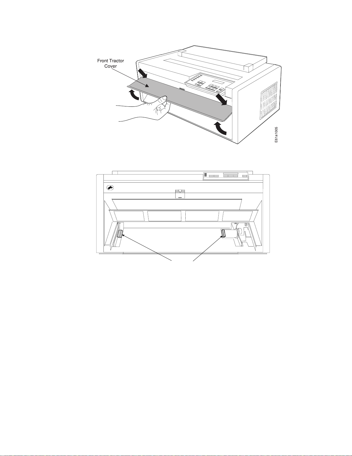
4. Remove the packing from each side in the front tractor area.
5. Close the front tractor cover.
Installing Operator Panel Overlay
To install the operator panel overlay, perform the following:
1. Remove the paper from the back of the operator panel overlay.
2. Align the bottom of the overlay; align each side.
3. Press the overlay in place at the bottom below the keys and then continue
working upwards until the overlay is pressed into place.
Packing
4 4247 Printer Model A00 User’s Guide
Page 27
xxxxx
xxxxx
xxxxxxxxx
xxxxx
xxxxxxxx
xxxx xxxx
xxxx
xxxxx
xxxx
xxxxx
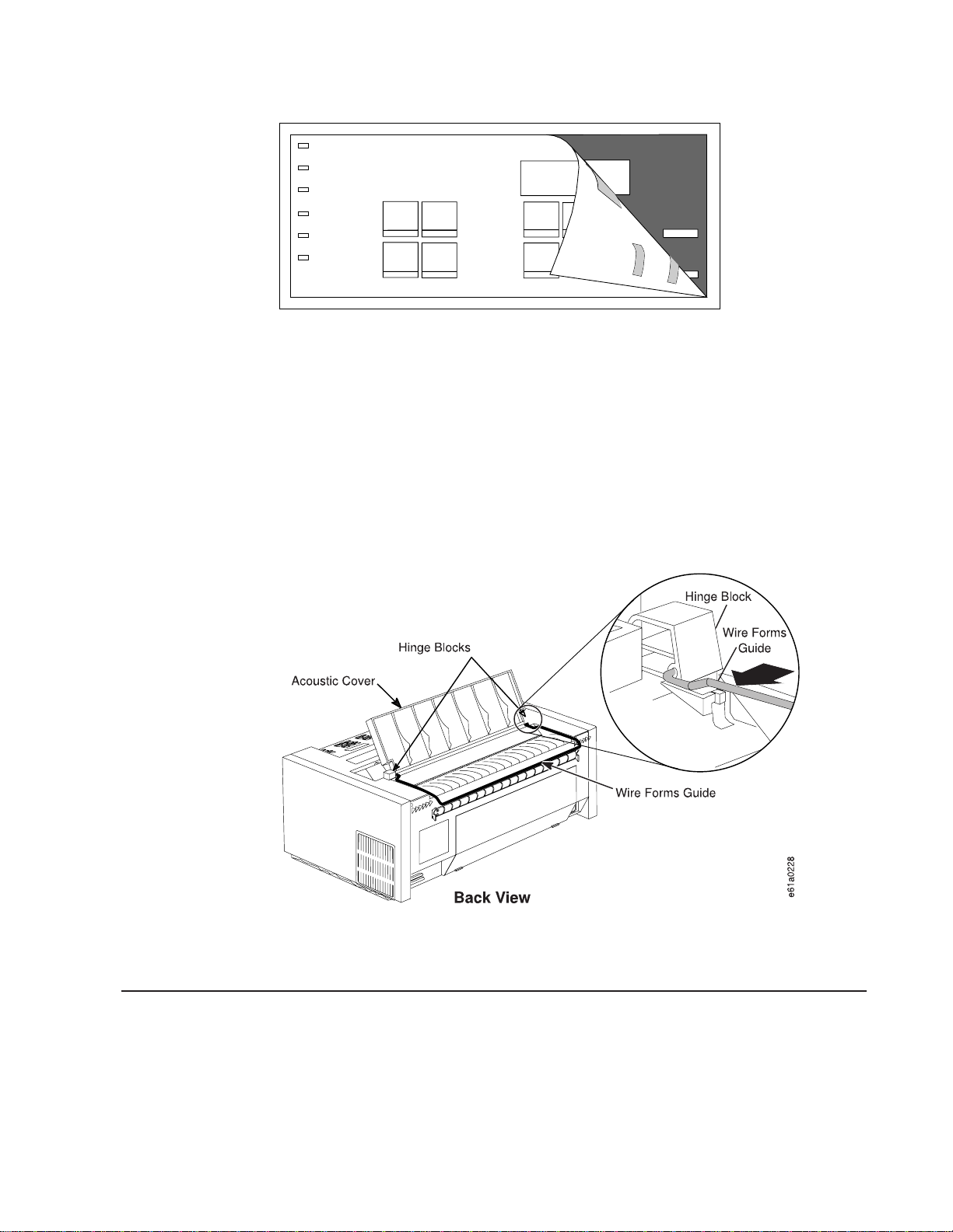
Installing Wire Forms Guide
The wire forms guide helps direct the forms for stacking in the Front Push and Rear
Push forms paths.
1. Open the acoustic cover and tilt it all the way back until it lays flat on the top
cover.
2. Insert one end of the wire forms guide into the hole on the right hinge block of
the acoustic cover. See orientation in Figure 1.
3. Insert the other end of the wire forms guide into the hole on the left hinge block
of the acoustic cover.
xxxxx
xxxx
xxxxxx
xxxxx
xxxx
xxxx
xxxxx
xxxxx
x
x
Figure 1. Installing Wire Forms Guide
4. Close the acoustic cover.
Locating Operator Accessible Areas and Controls
As with many IBM printers, a part that is colored blue or has a blue decal on it is for
your use in operating the printer. These blue marks indicate tabs and levers that
control settings and changes for the machine.
Chapter 1. Printer Setup 5
Page 28

Operator Panel
The operator panel consists of 6 status indicators, a one-line 16-character display,
12 function keys, and an audible alarm. Figure 2 on page 7 illustrates the operator
panel.
6 4247 Printer Model A00 User’s Guide
Page 29

Figure 2. Operator Panel
Throughout this book, procedures instruct you to view the display on the operator
panel, to view a status indicator, or to press a function key. The procedure then
describes the correct response.
Operator Panel Display
The 16-character display shows several types of messages:
v Information messages
v Intervention required messages
v Power On Configuration messages
v Program Configuration messages
v Error messages
Audible Alarm
The audible alarm beeps to let you know of a printer status condition or an error
such as an end-of-forms condition, forms jam, or top cover open.
Some operations you are asked to perform, such as opening the top cover when
the printer is online, cause the alarm to sound. In this case, press the Online key
before you open the top cover to prevent the alarm from sounding.
You can set the audible alarm off in the Power On Configuration menu. See “Alarm”
on page 102 for more information.
Status Indicators
Table 1 on page 8 describes the six status indicators shown in Figure 3 on page 8.
Chapter 1. Printer Setup 7
Page 30

Figure 3. Status Indicators
Table 1. Operator Panel Status Indicators
Status Indicators Continuously Lighted Blinking
v Printer READY
Online
Online
Auto Sheet Feed
(optional)
Manual Sheet Feed Selected
Front Push Selected
v Communicating with host
v Able to receive and print
Condition 1 Printer disabled and no data in input buffer
Condition 2 Printer in one of following modes:
v Power On Configuration
v Program Configuration
v Test and Diagnostic
Selected
Data in input buffer and Printer
not ready
offline (
Off
v Bin empty
v Forms jam
v Manual tray empty
v Forms jam
v End of forms (EOF)
v Forms jam
)
Rear Pull Selected
Rear Push Selected
8 4247 Printer Model A00 User’s Guide
v End of forms (EOF)
v Forms jam
v End of forms (EOF)
v Forms jam
Page 31

Function Keys
Table 1. Operator Panel Status Indicators (continued)
Status Indicators Continuously Lighted Blinking
Front Push and Rear
Pull
(Push Pull)
In Push Pull mode, both indicators operate together (this is one
forms path, with one set of forms loaded).
Push Pull selected
v End of forms (EOF)
v Forms jam
2 beginning on page 10 describes the 12 function keys shown in Figure 4 and
Figure 5 on page 10. You often will see them referred to as
keys
.
The eight keys highlighted in Figure 4 have one function each.
Figure 4. Eight Function Keys with One Function Each
The four keys highlighted in Figure 5 on page 10 each have two functions.
v The Micro ↑ key and Micro ↓ key position the forms up or down. The Font key
allows font selection and the Pitch key allows pitch selection.
Chapter 1. Printer Setup 9
Page 32

Figure 5. Four Function Keys with Two Functions Each
v The ↑, the ↓, the ←, and the → keys are active only during Power On Configuration
mode or Program Configuration mode to allow menu scrolling. See “Chapter 4.
Configuring Your Printer” on page 79 for configuration information.
Table 2. Operator Panel Function Keys
Function Key Description
Condition 1 If forms are not present in the current path and the
printer is in a
different forms paths.
wait
condition (
not ready
), press Path to select a
Condition 2 If forms are present and the printer is in a
condition (
that have been printed, and press Park to park the continuous
forms (or eject a single sheet, if loaded). The printer then enters an
end-of-forms
different path modes according to the forms path configurations
selected in the Power On Configuration menu.
If the printer is
v Move the forms up to the tear line for tearing (see “Tearing Off
Forms” on page 24).
v Move a form backward to its initial position [after a 10 second
(approximate) timeout occurs].
Reduces the printing noise level by two or three decibels; however,
the printer runs at half speed and throughput is reduced by one
half.
not ready
), tear off (at the tear bar) any continuous forms
(EOF) condition. You now can press Path to select the
ready
or a
wait
condition exists, press Tear to:
wait
10 4247 Printer Model A00 User’s Guide
Page 33

Table 2. Operator Panel Function Keys (continued)
Function Key Description
Condition 1 Press Park, if continuous forms are loaded in the print
area. The message 94 PARK:SURE? displays.
Press Park again (within 3 seconds), to park the continuous forms
that are in the Front Push, Rear Push, or Push Pull forms path or to
eject the forms in the Rear Pull path.
Before parking a form in the Front Push or Rear Push forms path,
press Tear and then tear the form at the tear bar.
Before parking a form in the Rear Pull or Push Pull forms paths,
tear the form off at the perforation below the front tractor cover.
Condition 2 If the printer is currently in Manual Sheet Feed mode,
press Park to eject a single cut-sheet page. The message 91 EJECT
FORM displays.
Condition 1 and Condition 2
If parking or ejecting does not result in clearing the forms jam
sensor within 24 inches, forms movement is stopped and a 02
FORMS JAM message displays. Press Online to clear the message.
If you wish to leave the Park function, press Online again.
Function 1 Micro ↑ Use this key for adjusting forms.
Press this key. The message MICRO FEED UP displays and the forms
move up in micro steps at an increasing speed (runs at a reduced
speed when the cover is open and the printer is offline).
Press and hold the Micro ↑ to process a continuous movement of
the forms.
For safety reasons, when the cover is open and the printer is
offline, only Micro ↑ and Micro ↓ are operational.
Function 2 ↑ Active only in Power On Configuration or Program
Configuration mode.
Press ↑ to scroll backward to the previous configuration menu
items.
Function 1 Font Use this key to select the available fonts (DP, DP
Text, Courier, Gothic, OCR-A, or OCR-B) for printing.
If you press Font while a job is printing, the current line finishes
printing before the new font takes affect.
If you select an available font which is not compatible with the pitch
currently selected, the default pitch for that font is automatically
selected.
Function 2 ← Active only in Power On Configuration mode or
Program Configuration mode.
Press ← to scroll backward through the previous values of a
selected configuration menu item.
Chapter 1. Printer Setup 11
Page 34

Table 2. Operator Panel Function Keys (continued)
Function Key Description
Function 1 Micro ↓ Press this key to adjust forms. The message
MICRO FEED DOWN displays, and the forms move down in micro steps
at increasing speed (reduced speed when the cover is open and
the printer is offline).
Hold down Micro ↓ to continuously feed forms.
For safety reasons, when the cover is open and the printer is
offline, only Micro ↑ and Micro ↓ are operational.
Function 2 ↓ Active only in Power On Configuration mode or
Program Configuration mode.
Press ↓ to scroll forward to the next configuration menu item.
Function 1 Pitch Press this key to select the available horizontal
spacings (5 CPI, 6 CPI, 7.5 CPI, 8.5 CPI, 10 CPI, 12 CPI, 15 CPI,
17.1 CPI, 20 CPI, or Prop) on the printer.
If you press Pitch while a job is printing, the current line finishes
printing before the new pitch value takes affect.
If you select an available font which is not compatible with the pitch
currently selected, the default pitch for that font is automatically
selected.
Function 2 →
Active only in Power On Configuration mode or Program
Configuration mode.
Press → to scroll forward through the values of a selected
configuration menu item.
Condition 1 If the printer is
Load/Form Feed to automatically load the forms according to the
forms types selected in the Program Configuration menu.
Condition 2 If the printer is
press Load/Form Feed to clear the forms path by ejecting the
single sheet or execute a form feed on the continuous forms. If
ejecting does not result in clearing the paper jam sensor within 24
inches, a 02 FORMS JAM message displays.
Press Online to clear the message.
Condition 3 If the ASF option is installed and selected, and the
forms path is not empty, press Load/Form Feed to eject the single
form. If the forms path is empty, a new single sheet will be loaded.
Advances the forms to the next printable line.
Press and hold Line Feed to continuously feed forms. Release the
key to stop feeding forms.
ready
and forms are not loaded, press
ready
and forms already are loaded,
12 4247 Printer Model A00 User’s Guide
Page 35

Table 2. Operator Panel Function Keys (continued)
Function Key Description
Condition 1
the self test printout.
(power on initialization)
Enters
test
mode and prints
Condition 2
Condition 3
v Makes the printer
display.
v Clears status messages from the display and turns off the alarm.
v If an EOF condition exists, prints the data buffer when forms are
loaded.
v If Tear has been previously pressed, causes the forms to move
backward from the tear position to the print line position.
Condition 4
v Takes the printer offline.
v If a job is printing, stops the printer after the line is printed.
Condition 5
adjustment test pattern.
Condition 6
a break signal to the host, and displays a 99 RESET message.
Condition 1 Press and hold this key while powering on (O) the
printer to enter the Power On Configuration menu.
Condition 2 If the printer is in a
or
ready
Configuration menu.
(test mode)
(wait)
(ready)
(Power On Configuration)
(Program Configuration)
without printing, press Menu/Enter to enter the Program
Stops the self test printout.
ready
if no error condition appears on the
Prints the bidirectional
Clears the input buffer, sends
wait
condition (Online indicator off)
Default Forms Path
When your printer was shipped, it was configured for the Front Push forms path.
This is the default and preferred forms path. You install the forms tractor for this
path, and also use it in this location for the Dual Push and the Push Pull forms
paths.
It is important that you verify that the Front Push forms path correctly feeds forms,
and that the printer prints with good print quality before setting up any other forms
path. Setting up this forms path first familiarizes you with setting and installing a
forms tractor, correctly loading, stacking, and tearing forms, and installing a ribbon.
After this verification, you maintain the printer with this forms path, or you may
configure the printer for any one of four other forms paths. IBM recommends you
use the Front Push forms path. See “Chapter 2. Considering Other Forms Paths” on
page 33 to select a different forms path, and “Preparing Printer for Selected Forms
Path” on page 44 set up a different forms path.
Condition 3
If the printer is in Power On Configuration mode or Program
Configuration mode, press this key to exit configuration mode.
Chapter 1. Printer Setup 13
Page 36

The front forms-tractor and rear forms-tractors are interchangeable. Either forms
tractor can be used in either location after you have set it for the forms path you
have selected.
Setting Up Front Push Forms Path (Default)
Figure 6 shows the Front Push forms path with the Manual Sheet Feed forms path.
Figure 6. Front Push Forms Path (with Manual Sheet Feed)
Setting Front Push Tractor
The Front Push forms tractor should be set to position (2), as shown in Figure 7 on
page 15.
If the tractor is set to position (1), perform the following:
1. Hold the tractor face-down with the electrical connector tab on the right side,
and pointing toward you.
2. Pull the bottom release levers toward you with your finger tips and push the
movable edge of the tractor down toward the flat surface with your thumbs or
the palms of your hands (position 2).
14 4247 Printer Model A00 User’s Guide
Page 37

Figure 7. Setting the Front Push Tractor to Straight (Viewed From Bottom)
Installing Front Push Tractor
Install the tractor in the Front Push forms path, as follows:
1. Ensure the printer is powered off (O).
2. Lift the bottom edge of the front tractor cover into the open position.
Figure 8. Opening Front Tractor Cover
CAUTION:
<3> The paper feed motor may get hot during operation. Avoid contact
when installing or removing the front tractor.
3. Rotate the hinged gear-protector cover forward and down. The cover must be
below the motor screw or the tractor will not seat.
Chapter 1. Printer Setup 15
Page 38

Figure 9. Opening Gear Protector Cover
4. If it is in place, remove the (black protective) cap from the electrical connector
on the tractor. Save this cap for future storage or shipping of the forms tractor.
5. Stand facing the front of the printer, holding the forms tractor with the tractor
doors facing up and the electrical connector tab on the right.
6. With both hands supporting the tractor shaft, hold down the tractor release lever
while gently pushing the forms tractor upward until the forms tractor clicks into
place on both sides. Ensure the tractor release levers are locked into place. The
electrical connector tab must be fully seated in the connector and the bottom of
the forms tractor should be even with the base of the printer.
Figure 10. Installing Front Tractor
7. Close the front tractor cover.
Your printer may have arrived with a second forms tractor. You will learn about
installing and using this forms tractor after completing “Chapter 1. Printer Setup” on
page 1.
16 4247 Printer Model A00 User’s Guide
Page 39

Installing Ribbon Cartridge
Note: IBM recommends that you use the IBM ribbon cartridge (Part Number
1053685). To order ribbon cartridges, contact your place of printer purchase
or call Lexmark at 1-800-438-2468.
To install the ribbon cartridge, follow these steps:
1. Remove the ribbon cartridge from the package. Locate the ribbon guide, snap
arm, ribbon advance knob, and the ribbon mounting pins.
2. Turn the ribbon advance knob in the direction of the arrow to take up any slack
in the ribbon. If the ribbon does not move, contact your place of ribbon
purchase to replace the ribbon cartridge.
3. Ensure the printer is powered off (O).
4. Open the top cover.
5. Slide the printhead to the center of the printer.
e61a5310
Figure 11. Sliding the Printhead to the Center of the Printer
6. With the snap arm raised higher than the ribbon lift assembly, insert the ribbon
guide between the ribbon shield and the printhead. Position the snap arm with
the small lever up onto the ribbon lift assembly. Push the snap arm down onto
the ribbon lift assembly until it snaps into place.
Chapter 1. Printer Setup 17
Page 40

7. Align the ribbon mounting pins on the left and right side of the ribbon cartridge
with the slots in the cartridge supports. Snap the ribbon cartridge down into
place.
8. Turn the ribbon advance knob again in the direction of the arrow to take up
slack in the ribbon.
9. Slide the printhead back and forth to ensure that the ribbon guide runs freely
along the ribbon.
10. If the ribbon is not running freely, or to ensure you have installed the ribbon
cartridge correctly, check that:
a. The left and right ribbon mounting pins are securely snapped into the
cartridge supports
b. There are no twists or folds in the ribbon
c. The ribbon is not catching on the printhead
d. The ribbon moves when you turn the ribbon advance knob in the direction
of the arrow. If the ribbon does not move, replace the ribbon cartridge.
Contact your place of ribbon cartridge purchase.
11. Close the top cover.
You can read about removing a ribbon cartridge in “Removing Ribbon Cartridge” on
page 133.
Connecting Electrical Power
Read the following safety information, and follow the steps for connecting electrical
power to the printer.
18 4247 Printer Model A00 User’s Guide
Page 41

1. The power switch is located on the lower left side of the printer. Ensure the
printer is powered off (O). DANGER
<1> The construction of this printer provides extra protection against
the risk of electric shock by grounding appropriate metal parts. The
extra protection may not function unless the power cord is connected
to a properly-grounded outlet. This printer has a grounding-type (3-wire)
power cord because grounding is necessary. It is the responsibility of
the customer or the person installing the printer to connect it to a
properly-grounded outlet. Seek professional assistance before using an
adapter or extension cord; such a device could interrupt the grounding
circuit.
If this printer is connected to an outlet that has been incorrectly
connected to the building wiring, serious electric shock could result.
2. The power connector is located at the lower left rear of the printer. Connect the
power cord to the power connector on the printer. Press firmly to ensure that the
plug is securely seated.
3. Plug the power cord into a properly-grounded electric receptacle.
Changing Display Language
The printer default language that appears in the operator panel display of your
printer is English. You can change the language by following these steps:
1. If the printer is powered on (|), power off (O) the printer.
2. Enter Power On Configuration mode. Press and continue to hold Menu/Enter
while powering on (|) the printer until (1) the message STARTING UP appears, (2)
the boxes on the operator panel display are solidly filled in, and (3) the
printhead stops. This takes about fifteen seconds. Do not release this key or
press any other keys until this completes.
3. Release Menu/Enter. The message PRINT OUT=NO displays.
4. Press ↓ until the message FUNCTIONS displays.
5. Press → and the message FRONT TEAR=NORM displays.
6. Press ↓ until the message MENU=xxxxxxxx displays (where xxxxxxxx can be
ENGLISH, ITALIANO, FRANCAIS, ESPANOL, DEUTSCH, PORTUGUES,
DANSK, or NEDERLANDS).
7. Press ← or → until the language you want to use displays.
8. Press Menu/Enter to save the setting and exit Power On Configuration mode.
Regardless of the language you select, STARTING UP always appears in English.
Chapter 1. Printer Setup 19
Page 42

Stacking Forms for Front Push Forms Path
Before you load forms into the printer you must consider the stacking of forms after
they pass through the printer. See Figure 12 for forms stacking recommendation for
the Front Push forms path.
must
The top of the input forms stack
parking forms.
Consider ordering the optional printer stand designed specifically for your printer.
Contact your IBM marketing representative for information.
Figure 12. Stacking Forms for Front Push. See “Optional Printer Stand” on page 32 if your
printer uses the optional printer stand. Consider ordering this option to serve as a shelf for
the forms stack.
be lower than the bottom of the printer when
Loading Forms into Front Push Forms Path
The term “loading forms” can have two interpretations:
v Physically putting the forms into the forms tractor
v Using the functions of the Load/Form Feed key
Here you will physically load the forms into the tractor, and then use one function of
the Load/Form Feed key to move the form to the print position. See “Function
Keys” on page 9 for a more complete description of Load/Form Feed.
Load the forms as follows:
1. Ensure the printer is powered off (O).
2. Open the front tractor cover to reveal the front forms-tractor.
3. Move the tractor locking levers to vertical to unlock the tractors.
4. Move the right tractor to the extreme right.
5. Move the left tractor to the tractor alignment mark on the tractor shaft. (This
controls the left print edge.)
6. Pull the left locking lever forward to lock the left tractor in place at the
alignment mark.
20 4247 Printer Model A00 User’s Guide
Page 43

7. Move the forms supports to be approximately equidistant between each other
and the tractors.
8. Lift the inner edge of each tractor to open the tractor doors.
9. Place the left edge of the form on the left tractor pins so that the form engages
about three left tractor pins. Close the left tractor door.
10. Move the right tractor to the left and under the forms until the holes along the
right edge of the form engage the same number of pins on the right tractor.
Ensure that the right edge of the forms is under the forms jam sensor. Close
the right tractor door.
11. If necessary, slide the right tractor either left or right to remove any slack in the
form, ensuring that the left and right tractor pins are centered in the holes of
the forms. Hold the right tractor in place. Pull the locking lever forward to lock
the right tractor.
Chapter 1. Printer Setup 21
Page 44

12. Close the front tractor cover.
13. Power on (|) the printer.
22 4247 Printer Model A00 User’s Guide
Page 45

14. After the printer warms up, if the Front Push indicator is not blinking, press
Path until the Front Push indicator is blinking and the message
01 END OF FORMS displays.
15. Press Load/Form Feed to feed the forms.
ready
16. Press Online to make the printer
.
Creating Print Test Sample (Self Test Printout-with Firmware Level)
Note: This pattern is intended for 14-inch forms. For optimum analysis, if available
load full-width [14 in. (355.6 mm)] forms before printing the Print Test
Sample.
The Print Test function allows you to print a sample. You can check printer
operations and print quality by running and reviewing this “Self Test Printout.” You
also can identify the level of firmware that is installed in your printer. The Print Test
can be printed using any forms path.
1. Ensure that the printer is powered off (O).
2. Press and continue to hold Online while powering on (|) the printer until (1) the
message STARTING UP appears, (2) the boxes on the operator panel display are
solidly filled in, and (3) the printhead stops. This takes about fifteen seconds. Do
not release this key or press any other keys until this completes.
3. Release Online. The message PRINT TEST displays. The Print Test will start
printing. Allow the test to fill at least one page.
4. Press Online to stop the Print Test after a full page has printed, or when you
feel you have a large enough printout to analyze.
Once the print test stops, compare your printout with the sample illustrated on the
next page. If you notice unsatisfactory results, see “Chapter 7. Resolving Printer
Problems” on page 139.
Save this printout for future reference.
Chapter 1. Printer Setup 23
Page 46

Tearing Off Forms
The forms can be advanced to position the perforation at the serrated, top-cover
tear line on the tear bar either automatically or by pressing Tear. Pressing Tear
moves continuous forms up to the top cover tear line and allows you to tear off your
printout. The forms move back to the print position after a 10-second delay.
24 4247 Printer Model A00 User’s Guide
Page 47

Note: If the printer is configured for FRONT TEAR=NO or REAR TEAR=NO, you
cannot back up the forms to park them. Break the forms at a perforation
ahead of where they enter the printer. Press Park twice, and the forms will
move forward until ejected from the printer.
Choosing Tear-Off Option
You can choose one of three tear-off options for the Front Push and the Rear Push
forms paths.
NORM (default)
AUTO When printing finishes, the forms automatically move up to the
NO Select NO for forms that should not be moved in a reverse
Note: Setting this option modifies how forms park. See “Parking Continuous
Forms” on page 29.
To change or check the Tear Mode, do the following:
Pressing TEAR moves the form to the tear line. After a 10-second
delay the forms will move back into the printer.
tear-off line. When the next print job arrives, the forms move back
into the printer.
direction through the printer, such as forms with attached labels or
forms with overlays. Choosing NO disables the Tear key.
1. Ensure the printer is powered off (O).
2. Press and continue to hold Menu/Enter while powering on (|) the printer until
(1) the message STARTING UP appears, (2) the boxes on the operator panel
display are solidly filled in, and (3) the printhead stops. This takes about fifteen
seconds. Do not release this key or press any other keys until this completes.
3. After start-up is complete, release Menu/Enter and the message PRINT OUT=NO
displays.
4. Press ↓ until the message FUNCTIONS displays.
5. Press → until the message FRONT TEAR=xxxx or REAR TEAR=xxxx displays. xxxx
can be NORM, AUTO,orNO. If you want to select a value other than the one
displayed, press ← or →.
6. To exit from Power On Configuration, press Menu/Enter. Your new value is
stored. The printer may take a few seconds to accept a change.
Checking and Adjusting Tear-Off Position
When the perforation on a form aligns with the serrated edge on the top cover, the
forms will break easily without creasing or leaving ragged edges. If the top of the
form that returns into the printer is ragged, ripped, torn, or creased, it may cause a
jam.
Checking Tear-off Position
To check the tear-off position, follow these steps:
1. Load forms.
2. Press Load/Form Feed to feed one form.
3. Press Tear to move the forms up to the top cover tear line.
Chapter 1. Printer Setup 25
Page 48

4. Open the acoustic cover, grasp one side of the form, pull it toward you, and
break the perforation against the serrated edge of the top cover.
Figure 13. Tear-Off Location. Shown With 11-Inch Long Forms
The perforation should align with the top cover tear line, and the tear should be
clean.
5. Close the acoustic cover.
Adjusting Tear-off Position
If, after checking the tear-off position, the perforation does not align with the top
cover tear line or if the tear is not clean, adjust the tear-off position.
1. Press Menu/Enter and PRINT OUT=NO displays.
2. Press ↓ and TEAR POS. ADJUST displays.
3. Press → and FRONT PATH=XXX displays. To adjust the tear-off position higher,
press →, increasing XXX. To adjust the tear-off position lower, press ←,
decreasing XXX.
4. If your printer uses the Rear Push forms path, press ↓ and REAR PATH=XXX
displays. To adjust the tear-off position higher, press →, increasing XXX. To
adjust the tear-off position lower, press ←, decreasing XXX.
To save your change:
1. Press Menu/Enter and STORE=QUIT displays.
26 4247 Printer Model A00 User’s Guide
Page 49

2. Press → and STORE=SAVE displays.
3. Press Menu/Enter again to save your change.
To quit without saving your change:
1. Press Menu/Enter. STORE=QUIT displays.
2. Press Menu/Enter to quit without saving any changes.
Checking Configuration
Printer configuration consists of Power On Configuration and Program
Configuration. “Chapter 4. Configuring Your Printer” on page 79 discusses printer
configuration.
If you change the forms path, you will need to configure the printer for your selected
forms path. Forms path configuration is discussed under the appropriate forms path
information in “Chapter 3. Setting Up Another Forms Path” on page 39.
There are many options to both Power On Configuration and Program
Configuration. You should print and save the current configuration. See “Chapter 4.
Configuring Your Printer” on page 79 for instructions about changing configuration
items.
Printing Power On Configuration Setup
IBM recommends that you print the Power On Configuration at initial setup and
after you have changed your configuration. Save this printout for future reference.
To print the Power On configuration:
1. Power off (O) the printer.
2. Press and continue to hold Menu/Enter while powering on (|) the printer until
(1) the message STARTING UP appears, (2) the boxes on the operator panel
display are solidly filled in, and (3) the printhead stops. This takes about fifteen
seconds. Do not release this key or press any other keys until this completes.
3. After start-up is complete, release Menu/Enter and the message PRINT OUT=NO
displays.
4. To print the current settings on the printer, press →. The message PRINT OUT=YES
displays and the Power On Configuration setup printout starts printing. Your
printout will look similar to the sample in Figure 14 on page 28. This sample also
depicts the default settings.
Chapter 1. Printer Setup 27
Page 50

Figure 14. Power On Configuration Printout
Printing Program Configuration Setup
IBM recommends that you print the Program Configuration at initial setup and after
you have changed your configuration. Save this printout for future reference.
You can save the configuration settings for as many as five forms paths. To print
the Program Configuration:
1. Press Menu/Enter. The printer goes offline, and the message PRINT OUT=NO
displays.
2. To print the settings on the printer, press →. The message PRINT OUT=YES
displays and the setup for the Program Configuration is printed.
Your printout will look similar to the sample in Figure 15 on page 29. This sample
printout shows three forms paths configured, and also depicts the default settings.
As shown in the sample, Rear Push is included on your printout even though your
printer may not be set up for the Rear Push forms path.
28 4247 Printer Model A00 User’s Guide
Page 51

Figure 15. Program Configuration Printout
After printing the Program Configuration, the display returns to PRINT OUT=NO. Press
Menu/Enter twice to exit configuration mode.
Parking Continuous Forms
Parking forms means that a forms type unloads from the print area, but still remains
on the tractors. When the forms in one forms path are parked, another forms path
or the Manual Sheet Feed can be selected, and the forms in that path will be
loaded in the print area. This can be configured to occur automatically, but you must
have performed the tear off. See “Checking and Adjusting Tear-Off Position” on
page 25.
Note: For successful forms parking, the top of the input forms stack
than bottom of the printer. See Figure 12 on page 20.
To park a forms type, follow these steps:
1. Press Tear. Tear off the forms at the top cover tear line.
2. Press Park and the message 94 PARK:SURE? displays.
3. Press Park immediately again to park the form.
must
be lower
Note: If you set TEAR=NO, tear off the forms at the forms-input side of the
printer. When you press the Park key, the message 92 EJECT:SURE?
displays. Press PARK to eject the forms.
Chapter 1. Printer Setup 29
Page 52

For additional information, see “Parking One Continuous Form and Loading Another
(Dual Push)” on page 59.
Setting Up Manual Sheet Feed Path
The 4247 Printer provides the ability to print on either single-part or multiple-part,
cut-sheet forms using the Manual Sheet Feed forms path. Manual Sheet Feed can
be used with the Front Push, the Rear Push, and the Dual Push forms paths. See
Figure 18 on page 41 for a depiction of the various paths.
The Manual Sheet Feed also allows you to overlay a single sheet on top of
continuous forms from another forms path, if your total page count does not exceed
8 parts. See “Choosing a Forms Path for Special Forms” on page 35 for limitations.
Setup the Manual Sheet Feed as follows:
1. Insert your thumb into the center opening and pull down to open the Manual
Sheet Feed tray.
2. Press Path until the Manual Sheet Feed indicator is blinking and the message
06 MANUAL FEED displays.
3. Move the left cut-sheet paper guide to the left alignment mark. Move the right
cut-sheet paper guide to the extreme right. You will not use the right cut-sheet
paper guide on this printer model.
30 4247 Printer Model A00 User’s Guide
Page 53

4. Push the paper into the printer until it covers the black patch on the input shelf.
Ensure the paper is straight against the left cut-sheet paper guide (shown as
shaded in the drawing).
5. To verify printer operation, print the Program Configuration as described in
“Printing Program Configuration Setup” on page 28.
Chapter 1. Printer Setup 31
Page 54

6. With Automatic Load set to YES in the Power On Configuration menu, after a
three-second timeout the paper is fed automatically into the printer, and your job
is printed.
7. When you are finished using the Manual Sheet Feed, return to Front Push by
pressing Path until the Front Push indicator is blinking, and the message 01
END OF FORMS displays.
Optional Printer Stand
The optional printer stand supports the printer and provides easier access to some
of the forms paths.
Load the forms as depicted in Figure 16. Input Front depicts where you load and
stack forms for the Front Push, Push Pull, and Dual Push forms paths. Input Rear
depicts where you load and stack forms for the Rear Push and Dual Push forms
paths. The Output is the same for Input Front and Input Rear.
Summary
Input
Front
Input
Rear
Figure 16. Optional Printer Stand
Output
e61a1303
By completing this chapter, you have set up your printer to use the Front Push
forms path and the Manual Sheet Feed.
If you are setting up the printer for a different forms path, proceed to “Chapter 2.
Considering Other Forms Paths” on page 33.
If your printer will use only the Front Push forms path with the Manual Sheet Feed,
and the factory default configuration is the correct choice for your printer, go to
“Chapter 5. Attaching Your Printer” on page 123 to learn how to attach the printer to
your computer.
See “Chapter 4. Configuring Your Printer” on page 79 to learn about changing the
printer configuration.
32 4247 Printer Model A00 User’s Guide
Page 55

Chapter 2. Considering Other Forms Paths
Choosing Other Forms Paths ...................33
Choosing a Forms Path for Your Needs ...............34
Choosing a Forms Path for Special Forms ..............35
Other Considerations for Forms ..................35
Description of Each Forms Path ..................36
Front Push Forms Path ....................36
Rear Push Forms Path ....................36
Dual Push Forms Paths ....................36
Rear Pull Forms Path .....................37
Push Pull Forms Path .....................37
Manual Sheet Feed ......................37
Choosing Other Forms Paths
IBM recommends you use the Front Push forms path whenever possible. A second
choice is the Rear Push. If the Front Push forms path does not meet your needs,
you can set up and configure the printer for other forms paths. You use a method
similar to that used when you set up the Front Push forms path in “Chapter 1.
Printer Setup” on page 1.
“Chapter 2. Considering Other Forms Paths” helps you choose a forms path other
than the default Front Push forms path. “Chapter 3. Setting Up Another Forms Path”
on page 39 helps you set up that forms path.
You may configure the printer for any one of five forms paths, plus the Manual
Sheet Feed path with the Front Push, the Rear Push, or the Dual Push paths (see
“Preparing Printer for Selected Forms Path” on page 44). Figure 17 on page 34
illustrates the five forms paths and the Manual Sheet Feed.
Each forms path is shown with the necessary tractors installed, and where the
forms input and output stacks should be located.
Notes:
1. The forms tractors are interchangeable between push and pull forms paths, and
front and rear forms paths.
2. The paper bail is installed for four of the five forms paths; it must be removed
for the Rear Pull forms path.
3. The Manual Sheet Feed can be used with three of the five forms paths.
4. The adjustable edge of each pin feed assembly must be set to properly guide
the forms in that forms path.
5. IBM recommends you test the performance in the printer of any forms you
intend to use.
© Copyright IBM Corp. 1995, 1998 33
Page 56

Figure 17. 4247 Printer Forms Paths
For the Dual Push forms paths or the Push Pull forms path, you will need to have
ordered and installed the optional, second forms tractor. Also consider ordering the
optional printer stand (see “Optional Printer Stand” on page 32). Contact your IBM
marketing representative for details or to order either item.
Choosing a Forms Path for Your Needs
Note: IBM recommends that whenever possible you use the Front Push forms path
for all your printing needs.
You might select a forms path based on other operating needs. Use the following
table when you are selecting a path. See “Chapter 8. Supplies, Forms, and Cables”
on page 151 for information about forms weights and thicknesses.
Table 3. Considerations For Choosing a Path
Front
Function
Autoload X X
Document on Demand
(DOD) / Tear Off
Tear Off Adjustment X X
Dual Path Forms Input X X Requires 2 tractors. IBM
Park X X Requires manual tear off
Quiet Key XXXX XReduces throughput by 50%
AFTA XXXX X
Top of Form X X
Vertical Adjustment X X
Horizontal Adjustment XXXX
ASF Mountable X * * See note 1.
Notes:
1. IBM recommends you remove the ASF before loading forms into the Rear Push forms path.
2. To use the Push Pull or Dual Push forms paths you must install the optional, second forms tractor.
Push
XX
Rear
Push
Rear
Pull
Push
Pull
Manual Sheet
Feed Comments
recommends optional Printer
Stand.
34 4247 Printer Model A00 User’s Guide
Page 57

Choosing a Forms Path for Special Forms
Note: IBM recommends selecting first the Front Push then the Rear Push as your
choices for forms paths.
The 4247 Printer can print on various sizes, dimensions, and weights of forms. IBM
recommends you test all forms for your application before ordering large quantities.
Use the following table when you are choosing which path to use for special forms
or paper.
Table 4. Selecting Forms Types
Front
Forms Type
Black-Back Forms X
Labels X X X X For Front Push, do not use Park
1-Part to 4-Part XXXX X
5-Part to 8-Part X X X X
Greater than 21 lb X X X X
Greater than 0.014 in.
thick
Prenumbered Forms X X
Critical Registration X X Easiest to load in Front Push.
Form stock with stickon
card or form, or forms of
varying thickness
Note: This printer does not support the following types of forms:
Greater than 8-part forms
Greater than 40 lb paper
Greater than 0.64 mm (0.025 in.) total forms thickness
Less than 15 lb paper
Less than 0.08 mm (0.003 in.) paper thickness
Push
XXXX
Rear
Push
Rear
Pull
X X If multiple thicknesses on each
Push
Pull
Manual Sheet
Feed Comments
Set PERF SAFE=YES for 8-part
forms
sheet, remove Paper Bail
Other Considerations for Forms
Consider the following items, unless Table 3 on page 34 or Table 4 provides other
direction.
v IBM recommends you test the Park function when you intend to run multiple-part
forms. If you notice forms feed problems, disable the Park function, and use the
Push Pull forms path.
v When your printer is loaded with different forms in the Front Push and the Rear
Push tractors, your job (or the operator) can select the desired source and
alternate between the two paths. The operator will need to tear off the forms for
the path from which the printer is alternating.
v See “Chapter 8. Supplies, Forms, and Cables” on page 151 for recommended
paper weight and thickness.
Chapter 2. Considering Other Forms Paths 35
Page 58

v For forms stacking convenience, consider ordering the optional printer stand. See
“Optional Printer Stand” on page 32, or contact your IBM marketing
representative to order.
v Consider the following when using the optional Automatic Sheet Feeder:
– You cannot use Rear Pull or Push Pull with the optional Automatic Sheet
Feeder installed.
– To improve access, remove the ASF when loading the Rear Push forms path.
Description of Each Forms Path
Use the following information and the information in “Choosing a Forms Path for
Your Needs” on page 34 and “Choosing a Forms Path for Special Forms” on
page 35 to help you select an alternate forms path for your forms and needs.
Front Push Forms Path
The Front Push forms path is the default
forms path that you set up in “Default Forms
Path” on page 13.
Rear Push Forms Path
Dual Push Forms Paths
The Dual Push forms paths is a combination
of the Front Push and the Rear Push forms
paths. This provides
forms can be loaded. You can alternate
printing between the two paths.
two paths
into which the
36 4247 Printer Model A00 User’s Guide
Page 59

Rear Pull Forms Path
Push Pull Forms Path
Manual Sheet Feed
Manual Sheet Feed can be used with the Front Push, the Rear Push, and the Dual
Push forms paths. It is shown here in use with the Dual Push forms path, which is a
combination of the Front Push and the Rear Push forms paths.
The Push Pull forms path is a combination of
the Front Push and the Rear Pull forms
paths. Unlike the Dual Push paths into which
you can load two forms, the Push Pull forms
path is
one path
.
Chapter 2. Considering Other Forms Paths 37
Page 60

38 4247 Printer Model A00 User’s Guide
Page 61

Chapter 3. Setting Up Another Forms Path
Summarizing Forms Path Set Up..................39
Changing to a Different Forms Path .................41
Identifying Existing Forms Path .................42
Identifying New Forms Path...................42
Removing Existing Forms Tractor.................42
Removing Front Forms Tractor.................42
Removing Rear Forms Tractor.................43
Preparing Printer for Selected Forms Path ..............44
Setting Forms Guide Deflector ..................44
Setting Push-Pull Selector ...................46
Removing or Installing Paper Bail.................47
Removing Paper Bail ....................48
Installing Paper Bail.....................48
Setting Forms Tractors.....................50
Setting Up and Configuring Front Push Forms Path ...........52
Setting Up Rear Push Forms Path .................53
Installing Rear Push Tractor...................53
Configuring Forms Path for Rear Push...............54
Loading Forms For Rear Push..................55
Setting Up Dual Push Forms Paths .................57
Preparing Dual Push Forms Paths ................58
Configuring Printer for Linking Dual Push ..............59
Parking One Continuous Form and Loading Another (Dual Push) .....59
Parking Continuous Forms ..................59
Switching the Forms Path ..................60
Setting Up Rear Pull Forms Path ..................60
Installing Rear Pull Tractor ...................61
Configuring Forms Path for Rear Pull ...............63
Loading Forms For Rear Pull ..................64
Setting Up Push Pull Forms Path..................70
Installing Push Pull Tractors...................71
Configuring Forms Path for Push Pull ...............71
Loading Forms For Push Pull ..................72
Summarizing Forms Path Set Up
Table 5 summarizes the settings for all forms paths. See Figure 18 on page 41 to
help you understand the numbers used in Table 5. The remainder of this chapter
describes the settings for all the forms paths except for the Front Push and Manual
Sheet Feed which you read about in “Chapter 1. Printer Setup” on page 1.
Table 5. Review of Forms Paths Settings
Forms Path
Front Push Open Push Installed 2
Rear Push Open Push Installed 2
Dual Push Open Push Installed
Rear Pull Closed Pull Not installed 1
© Copyright IBM Corp. 1995, 1998 39
Forms Guide
Deflector
Push-Pull
Selector
Paper Bail Forms Tractor
Rear, 2
Front, 2
Page 62

Table 5. Review of Forms Paths Settings (continued)
Forms Path
Push-Pull Closed Pull Installed
Manual Open —* Installed —*
Note: * Your choice is not affected by these settings.
Forms Guide
Deflector
Push-Pull
Selector
Paper Bail Forms Tractor
Table 6 summarizes the configuration settings for all the forms paths.
Table 6. Review of Configuration Settings
Forms Path Setting
Power on Configuration Menu
PULL= SEQUENCE
Front Push No None Front Push
Rear Push No None Rear Push
None if different
forms in each path
Dual Push No
FR+RR if same forms
in each path
Rear Pull Yes None Rear Pull
Push-Pull Push+Pull None
Manual —* —* Manual Sheet Feed
Note: * The setting you choose is not affected by the value in this category.
Press Path Key
Until Indicator is
Rear, 1
Front, 2
Blinking for:
Front Push or
Rear Push
Rear Pull and
Front Push
40 4247 Printer Model A00 User’s Guide
Page 63

Figure 18. Tractors and Forms Paths
Changing to a Different Forms Path
To change the forms path, you will perform the following tasks:
1. Identify the existing forms path (see “Identifying Existing Forms Path” on
page 42).
2. Identify the new forms path (see “Identifying New Forms Path” on page 42).
3. Remove the existing forms tractor, if necessary (see “Removing Existing Forms
Tractor” on page 42).
4. Prepare the new forms path (see “Preparing Printer for Selected Forms Path” on
page 44).
Chapter 3. Setting Up Another Forms Path 41
Page 64

If your printer has an optional Automatic Sheet Feeder (ASF) installed, see the
4247 Printer Automatic Sheet Feeder Guide
option. Figure 19 illustrates the Automatic Sheet Feature.
Figure 19. Automatic Sheet Feeder
Identifying Existing Forms Path
Figure 20 illustrates the five forms paths and the Manual Sheet Feed. It also depicts
the forms tractors used in each forms path. Notice that the Manual Sheet Feed can
be used only with the Front Push, Rear Push, and Dual Push forms paths.
for any information concerning this
Figure 20. Forms Paths with Forms Tractor Locations
Identifying New Forms Path
If you have not selected a forms path, see “Chapter 2. Considering Other Forms
Paths” on page 33.
Removing Existing Forms Tractor
If you need to remove a forms tractor, go to the appropriate topic listed below:
Removing Front Forms Tractor
1. Power off (O) the printer.
42 4247 Printer Model A00 User’s Guide
Page 65

2. Open the front tractor cover.
CAUTION:
<3> The paper feed motor may get hot during operation. Avoid contact when
installing or removing the front forms tractor.
3. While holding both sides of the forms tractor by the round shaft, release the
lever on each side of the forms tractor. Lift out the forms tractor.
CAUTION:
<4> Close the gear protector cover immediately after removing the front
forms tractor.
4. Close the gear protector cover and the front tractor cover.
5. Reinstall the black protective cap on the electrical connector if you are not
installing this forms tractor into the printer. Store the forms tractor.
Removing Rear Forms Tractor
1. Power off (O) the printer.
2. Open the top cover and the forms guide.
3. While holding both sides of the forms tractor by the round shaft, release the
lever on each side of the forms tractor. Lift out the forms tractor.
Chapter 3. Setting Up Another Forms Path 43
Page 66

4. Close the forms guide and the top cover.
5. Reinstall the black protective cap on the electrical connector if you are not
installing this forms tractor into the printer. Store the forms tractor.
Preparing Printer for Selected Forms Path
You must perform the following procedures for the forms path you have chosen:
1. “Setting Forms Guide Deflector”
2. “Setting Push-Pull Selector” on page 46
3. “Removing or Installing Paper Bail” on page 47
4. “Setting Forms Tractors” on page 50
Setting Forms Guide Deflector
See Table 7 for the correct setting for your selected forms path.
Table 7. Setting the Forms Guide Deflector
Forms Guide
Deflector
Front Push
with Manual
Open Open Open Closed Closed
Rear Push
with Manual
Dual Push
with Manual
Rear Pull Push Pull
Set the forms guide deflector as follows:
1. Press Online to take the printer offline.
2. Open the top cover and the forms guide (see Figure 21 on page 45).
44 4247 Printer Model A00 User’s Guide
Page 67

Figure 21. Forms Guide
Figure 22 on page 46 shows the two settings for the forms guide deflector. Use
the open position for push, and the closed position for pull (see Table 7 on
page 44).
Chapter 3. Setting Up Another Forms Path 45
Page 68

Figure 22. Forms Guide Deflector
3. Grasp the forms guide deflector with one hand and the plastic rib on the forms
guide with the other hand.
4. While pulling the forms guide deflector and the plastic rib apart, move first the
right side then the left side of the forms guide deflector to be either above or
below the metal pins. The correct position is noted in Table 7 on page 44.
Figure 22 shows the forms guide deflector being moved from the closed (pull)
position to the open (push) position.
5. Close the forms guide and the top cover.
Setting Push-Pull Selector
See Table 8 for the correct setting you will make for your selected forms path.
Table 8. Setting the Push-Pull Selector
Push-Pull
Selector
46 4247 Printer Model A00 User’s Guide
Rear Push
with Manual
Push Push Push Pull Pull
Dual Push
with Manual
Rear Pull Push Pull
Page 69

Figure 23. The Push-Pull Selector. The arrows and words “Push” and “Pull” are provided
here for clarity.
Set the Push-Pull selector as follows:
1. Press Online to take the printer offline.
2. Open the top cover and the forms guide, and locate the Push Pull selector. Use
Table 8 on page 46 to help you set the selector.
Push position—Slide the Push-Pull selector down and to the rear. Ensure that
the upper and the lower gears are correctly positioned, as shown for push.
Pull position—Slide the Push-Pull selector up and to the front. Ensure that the
upper and the lower gears are correctly positioned, as shown for pull.
3. Close the forms guide and the top cover.
Removing or Installing Paper Bail
See Table 9 to determine if the paper bail should be installed or not installed for
your selected forms path.
Table 9. Installing or Not Installing the Paper Bail
Front Push
with Manual
Paper Bail Installed Installed Installed Not Installed Installed
Rear Push
with Manual
Dual Push
with Manual
Rear Pull Push Pull
Chapter 3. Setting Up Another Forms Path 47
Page 70

Removing Paper Bail
1. Open the top cover and the forms guide.
2. Remove the ribbon cartridge. See “Removing Ribbon Cartridge” on page 133.
3. Move the printhead to the far right.
4. Grasp the paper bail and rotate it toward the front of the printer until it snaps
loose. Some force is required.
Figure 24. Rotating the Paper Bail
5. Using care not to damage the thin plastic strip on the paper bail, lift the paper
bail up and out of the printer.
Figure 25. Removing the Paper Bail
6. Install the ribbon cartridge. See “Installing Ribbon Cartridge” on page 17.
7. Close the forms guide and the top cover.
8. Store the paper bail. You may need to reinstall the paper bail if you change the
forms path.
Installing Paper Bail
1. Press Online to take the printer offline.
2. Open the top cover and forms guide.
3. Remove the ribbon. (See “Removing Ribbon Cartridge” on page 133.)
4. Move the printhead to the far right.
5. Hold the paper bail with the plastic strip toward you. Rotate the paper bail so
the plastic strip is pointing down.
48 4247 Printer Model A00 User’s Guide
Page 71

6. Using care not to damage the plastic strip on the paper bail, insert the ends of
the bail into the printer frame as shown in Figure 26.
Figure 26. Installing the Paper Bail
7. Rotate the paper bail, moving the top toward the rear, as shown in Figure 27.
Ensure the paper bail snaps into place.
e61z5303
Figure 27. Rotating the Paper Bail into Position
8. Ensure that the paper bail (level 1 or level 2) is installed correctly. Press on the
areas that are identified by arrows in Figure 28 on page 50. If your printer has
a level 1 paper bail, ensure the paper bail is snapped into the closed position.
See Figure 28 on page 50.
Chapter 3. Setting Up Another Forms Path 49
Page 72

Figure 28. Correct Installation of Either a Level 1 or a Level 2 Paper Bail
9. Install the ribbon cartridge. See “Installing Ribbon Cartridge” on page 17.
10. Close the forms guide and the top cover.
Setting Forms Tractors
See Table 10 and Figure 29 on page 51 for the correct tractor settings for each
forms path.
Table 10. Setting the Tractors. Numbers in Table Match Numbers in Figure 29 on page 51.
Tractor
Settings
Set the forms tractors to Position 1 or Position 2 for your forms path, as shown in
Figure 29 on page 51.
Front Push
with Manual
22
Rear Push
with Manual
Dual Push
with Manual
2 (Front
Push) and
(Rear Push)
Rear Pull Push Pull
1 (Rear Pull)
1
2 (Front
Push)
50 4247 Printer Model A00 User’s Guide
Page 73

Figure 29. Setting Forms Tractors
If a forms tractor is not set to the desired position, perform the following:
1. With the forms tractor positioned as shown in Figure 29, move the release
levers in the direction indicated and move the edge of the forms tractor to the
new position.
2. Ensure that the forms tractor fully locks into position. Position 1 is for the Rear
Pull forms tractor in either the Rear Pull or Push Pull mode.
Next, you will perform the following tasks for your selected forms path.
1. Install the necessary tractors.
2. Configure the printer for the selected forms path.
3. Load your forms.
4. Print the configuration for future reference and to verify printer operation.
Chapter 3. Setting Up Another Forms Path 51
Page 74

Table 11 directs you to information about the forms path of your choice.
Table 11. Information About Your Selected Forms Path
Forms Path Where to Find Your Next Task
Front Push “Setting Up and Configuring Front Push Forms Path”
Rear Push “Setting Up Rear Push Forms Path” on page 53
Dual Push “Setting Up Dual Push Forms Paths” on page 57
Rear Pull “Setting Up Rear Pull Forms Path” on page 60
Push Pull “Setting Up Push Pull Forms Path” on page 70
Setting Up and Configuring Front Push Forms Path
Figure 30 shows the Front Push forms path with Manual Sheet Feed.
Figure 30. Front Push and Manual Sheet Feed Forms Paths
The Front Push tractor is used for the Dual Push and the Push Pull forms paths, as
well as the Front Push forms path. The printer is shipped to you with the Front
Push forms path set as the default.
1. Ensure the correct settings are made for the Front Push forms path. Refer to
the tables in “Summarizing Forms Path Set Up” on page 39.
2. Perform the steps in “Installing Front Push Tractor”on page 15.
3. Configure the printer for the Front Push forms path by following these steps:
a. Power off (O) the printer.
b. Enter Power On Configuration mode. To do this, press and continue to hold
Menu/Enter while powering on (|) the printer, until (1) the message STARTING
UP appears, (2) the boxes on the operator panel display are solidly filled in,
and (3) the printhead stops. This takes about fifteen seconds. Do not
release this key or press any other keys until this completes.
c. Release Menu/Enter and the message PRINT OUT=NO displays.
d. Press ↓ and the message PULL=xxxxxxxxx displays, where xxxxxxxxx can be
NO, YES,orPUSH+PULL. If xxxxxxxxx is not NO, press ← or → until NO is
displayed.
52 4247 Printer Model A00 User’s Guide
Page 75

e. Press Menu/Enter to save the settings and exit Power On Configuration
mode. This takes a few seconds. Do not press any keys until this
completes.
f. Press Path until the Front Push indicator is blinking and the message
01 END OF FORMS displays.
g. Press Online to quiet the alarm and put the printer online.
4. Perform the steps in “Loading Forms into Front Push Forms Path” on page 20.
Your 4247 Printer is ready to print. See “Printing Power On Configuration Setup” on
page 27 and “Printing Program Configuration Setup” on page 28 to print the
configuration. If you do not want to use the printer defaults for forms settings (such
as Line Spacing, Page Length, or Top of Form), see “Program Configuration” on
page 106.
Setting Up Rear Push Forms Path
Figure 31 shows the Rear Push forms path with Manual Sheet Feed.
Figure 31. Rear Push Forms Path with Manual Sheet Feed
Ensure the correct settings are made for the Rear Push forms path. Refer to the
tables in “Summarizing Forms Path Set Up” on page 39.
Additionally you will need to perform the following tasks:
1. “Installing Rear Push Tractor”
2. “Configuring Forms Path for Rear Push” on page 54
3. “Loading Forms For Rear Push” on page 55
Installing Rear Push Tractor
Install the forms tractor in the Rear Push forms path as follows:
1. Power off (O) the printer.
2. Open the top cover and the forms guide.
Chapter 3. Setting Up Another Forms Path 53
Page 76

3. Stand facing the front of the printer. Hold the forms tractor with the tractor doors
toward you, and the electrical connector tab on the left pointing down.
4. Use both hands to support the forms tractor by the tractor shaft. Position the
electrical connector tab above the rear tractor electrical connector on the left
side of the printer and the two lowest pins on the right. The forms tractor will
rest on the lowest pin on the right, and lock onto the next higher pin.
Figure 32. Installing Rear Push Tractor. Paper bail shown removed for clarity.
5. Adjust the forms tractor until it clicks on both sides and the electrical connector
tab is fully seated in the connector receiver.
6. Close the forms guide and the top cover.
Configuring Forms Path for Rear Push
To configure the printer for the Rear Push forms path:
1. Power off (O) the printer.
2. Enter Power On Configuration mode. To do this, press and continue to hold
Menu/Enter while powering on (|) the printer, until (1) the message STARTING UP
appears, (2) the boxes on the operator panel display are solidly filled in, and (3)
the printhead stops. This takes about fifteen seconds. Do not release this key or
press any other keys until this completes.
3. Release Menu/Enter and the message PRINT OUT=NO displays.
4. Press ↓ and the message PULL=xxxxxxxxx displays, where xxxxxxxxx can be NO,
YES,orPUSH+PULL. If xxxxxxxxx is not NO, press ← or → until NO is displayed.
5. Press Menu/Enter to save the settings and exit Power On Configuration mode.
This takes a few seconds. Do not press any keys until this completes.
6. Press Path until the Rear Push indicator is blinking and the message
01 END OF FORMS displays.
7. Press Online to quiet the alarm and put the printer online.
54 4247 Printer Model A00 User’s Guide
Page 77

Loading Forms For Rear Push
Note: IBM recommends you remove the Automatic Sheet Feeder before loading
forms into the Rear Push forms path.
The Rear Push forms path can accept up to 4-part forms with a maximum thickness
of 0.35 mm (0.014 in.).
1. Stack the forms as shown in Figure 33. The top of the input forms stack should
be lower than the bottom of the printer.
Figure 33. Stacking Forms for Rear Push. See page 32 if your printer uses the optional
printer stand. Consider ordering this option to serve as a shelf for the forms stacks.
2. Press Online to take the printer offline.
3. Open the rear tractor door located at the back of the printer (see Figure 34 on
page 56 for location).
4. Open the top cover and the forms guide.
5. Move the tractor locking levers to unlock the tractors.
6. Move the right tractor to the extreme right.
7. Move the left tractor to the alignment mark on the tractor shaft. This controls
the left print edge.
8. Move the left locking lever to the lock position to lock the left tractor in place at
the alignment mark.
9. Move the forms supports to support the width of the forms.
10. Open the tractor doors.
Chapter 3. Setting Up Another Forms Path 55
Page 78

11. From the back of the printer, insert the forms (with the print side facing down)
through the rear tractor door. Guide the forms over the forms tractors.
Figure 34. Installing Forms at the Rear of the Printer
12. From the front of the printer, place the left edge of the form under the forms
jam sensor, and on the left tractor pins so that the form engages about three
left tractor pins. Close the left tractor door.
13. Move the right tractor to the left and under the form until the holes along the
right edge of the form engage the same number of pins on the right tractor.
Close the right tractor door.
14. If necessary, slide the right tractor either left or right to remove any slack in the
form, ensuring that the left and right tractor pins are centered in the holes of
the form. Hold the right tractor in place and lock the right locking-lever by
pushing it away from you.
56 4247 Printer Model A00 User’s Guide
Page 79

Figure 35. Aligning Forms for Rear Push Forms Path
15. Close the forms guide and the top cover.
16. Press Load/Form Feed to load the forms.
17. Press Online to make the printer
Your 4247 Printer is ready to print. See “Printing Power On Configuration Setup” on
page 27 and “Printing Program Configuration Setup” on page 28 to print the
configuration. If you do not want to use the printer defaults for forms settings (such
as Line Spacing, Page Length, or Top of Form), see “Program Configuration” on
page 106.
Setting Up Dual Push Forms Paths
This forms path configuration lets you alternate between the Front Push and Rear
Push forms paths. You can have forms loaded in the Front Push position and
additional forms loaded in the Rear Push position, or you can have the same type
of forms loaded in both positions. If the same type of forms are loaded in both
forms paths and you want the printer to alternate automatically from Front Push to
Rear Push or vice versa, set Sequence=FR+RR in the Power On Configuration
Menu (see “Configuring Printer for Linking Dual Push” on page 59).
If you have different forms types loaded in the Front Push forms path than in the
Rear Push forms path, the operator or the job must ensure that the correct forms
path is used. See “Parking One Continuous Form and Loading Another (Dual
Push)” on page 59.
ready
.
Figure 36 on page 58 shows the Dual Push forms paths with Manual Sheet Feed.
Chapter 3. Setting Up Another Forms Path 57
Page 80

Figure 36. Dual Push Forms Paths with Manual Sheet Feed
Ensure the correct settings are made for the Dual Push forms path. Refer to the
tables in “Summarizing Forms Path Set Up” on page 39.
Preparing Dual Push Forms Paths
Because this forms path configuration lets you alternate (either manually or
automatically) between the Front Push and Rear Push forms paths, you will load
forms into both forms paths.
1. Stack the forms as shown in Figure 37. The top of the input forms stack should
be lower than the bottom of the printer.
Figure 37. Stacking Forms for Dual Push. See page 32 if your printer uses the optional
printer stand.
2. If the Front Push forms path is not setup, go to “Setting Up and Configuring
Front Push Forms Path” on page 52 and set up the Front Push forms path, and
then return here to step 3.
3. Park the forms in the Front Push forms path (see “Parking Continuous Forms”
on page 29), and then return here to step 4.
4. If the Rear Push forms path is not setup, go to “Setting Up Rear Push Forms
Path” on page 53 and set up the Rear Push forms path. Return here to step 5.
5. Park the forms in the Rear Push forms path (see “Parking Continuous Forms”
on page 29). Return here to “Configuring Printer for Linking Dual Push” on
page 59.
58 4247 Printer Model A00 User’s Guide
Page 81

Go to “Configuring Printer for Linking Dual Push” if you intend to load the
forms in both the Front Push and the Rear Push forms paths. Go to “Parking One
Continuous Form and Loading Another (Dual Push)” if you intend to load
forms in the Front Push forms path than in the Rear Push forms path.
Configuring Printer for Linking Dual Push
If you are using the same type of forms in the Front Push and Rear Push tractors
and you want the printer when it runs out of forms in the front forms path to switch
automatically to the forms in the rear forms path, continue with these steps. This is
known as linking.
Configure the printer for linked Dual Push by following these steps:
1. Enter Power On Configuration mode:
a. Press and hold Menu/Enter while powering on (|) the printer.
b. Continue holding Menu/Enter until the message STARTING UP appears, the
sixteen boxes on the operator panel are solidly filled in, and all printer
motion has stopped.
2. Release Menu/Enter and the message PRINT OUT=NO displays.
3. Press ↓ until the message FUNCTIONS displays.
4. Press → until the message FRONT TEAR=xxxx displays, where xxxx can be NORM,
AUTO,orNO.
5. Press ↓ until the message SEQUENCE=xxxxxx displays, where xxxxxx can be NONE,
FR+RR, ASF1+2,orASF123. If xxxxxx is not FR+RR, press ← or → until FR+RR is
displayed.
6. Press Menu/Enter to save the settings and exit Power On Configuration mode.
This takes a few seconds. Do not press any keys until this completes.
same
different
Your 4247 Printer is ready to print. See “Printing Power On Configuration Setup” on
page 27 and “Printing Program Configuration Setup” on page 28 to print the
configuration. If you do not want to use the printer defaults for forms settings (such
as Line Spacing, Page Length, or Top of Form), see “Program Configuration” on
page 106.
Parking One Continuous Form and Loading Another (Dual Push)
If you have different continuous forms loaded in the Front Push and the Rear Push
forms paths, the operator can have the printer switch between forms paths. This
section explains how you can take advantage of this feature and free yourself from
having to reload forms when you need to print on a different form.
Parking Continuous Forms
Parking forms means that a forms type unloads from the print area, but still remains
on the tractors. When the forms in one continuous forms path are parked, another
forms path or the Manual Sheet Feed can be selected, and the forms in that path
will be loaded for printing. This can be configured to occur automatically, but you
must have performed the tear off. See “Checking and Adjusting Tear-Off Position”
on page 25.
must
For successful forms parking, the input forms stack
Figure 37 on page 58 provides an example.
be lower than the printer.
Chapter 3. Setting Up Another Forms Path 59
Page 82

Park forms as follows:
1. Press Tear and tear off forms at the top cover tear line.
2. Press Park and 94 PARK:SURE? displays.
3. Press Park immediately again to park the forms.
If the printer is configured for FRONT TEAR=NO or REAR TEAR=NO, you cannot
back up the forms to park them. Break the forms at a perforation before they enter
the printer. Press Park twice, and the forms will move forward until ejected from the
printer.
Switching the Forms Path
Follow these steps to select another forms path:
1. Ensure that a form is in the tractors of the desired, alternate forms path. (You
may want to review “Preparing Printer for Selected Forms Path” on page 44.)
2. Press Path until the indicator for the other forms path lights. The new form will
load automatically.
Your 4247 Printer is ready to print. See “Printing Power On Configuration Setup” on
page 27 and “Printing Program Configuration Setup” on page 28 to print the
configuration. If you do not want to use the printer defaults for forms settings (such
as Line Spacing, Page Length, or Top of Form), see “Program Configuration” on
page 106.
Setting Up Rear Pull Forms Path
To use this forms path, the following
v Automatic Sheet Feeder (ASF)
v Front Push forms tractor (See “Setting Front Push Tractor” on page 14.)
v Paper bail (See “Removing or Installing Paper Bail” on page 47.)
not
Note: It is
Rear Pull or the Push Pull forms paths. Manual can be selected from the
operator panel, but to use it, you will need to re-configure the forms path
both before and after using Manual. See “Summarizing Forms Path Set Up”
on page 39.
Figure 38 on page 61 shows the Rear Pull forms path.
recommended to select Manual when the printer is set for either the
must
be removed from the printer:
60 4247 Printer Model A00 User’s Guide
Page 83

Figure 38. Rear Pull Forms Path
Ensure the correct settings are made for the Rear Pull forms path. Refer to the
tables in “Summarizing Forms Path Set Up” on page 39.
Additionally, you will need to perform the following tasks:
1. “Installing Rear Pull Tractor”
2. “Configuring Forms Path for Rear Pull” on page 63
3. “Loading Forms For Rear Pull” on page 64
Installing Rear Pull Tractor
Install the forms tractor in the Rear Pull forms path as follows (see Figure 38):
1. Power off (O) the printer.
2. Open the top cover and the forms guide.
3. Stand facing the front of the printer. Hold the forms tractor with the tractor doors
toward you and the electrical connector tab on the left.
Chapter 3. Setting Up Another Forms Path 61
Page 84

4. To install the rear forms tractor, support the tractor with both hands on the round
tractor shaft. Position the electrical connector tab above its connector on the left
side of the printer and the two lowest pins on the right.
5. Adjust the forms tractor until it clicks on both sides and the electrical connector
tab is fully seated in the connector.
62 4247 Printer Model A00 User’s Guide
Page 85

6. Close the forms guide and top cover.
Configuring Forms Path for Rear Pull
To configure the printer for the Rear Pull forms path:
1. Enter Power On Configuration mode:
a. Press and continue to hold Menu/Enter while powering on (|) the printer,
until (1) the message STARTING UP appears, (2) the boxes on the operator
panel display are solidly filled in, and (3) the printhead stops. This takes
about fifteen seconds. Do not release the key or press any other keys until
this completes.
b. Press Online to quiet the audible alarm.
2. Release Menu/Enter and the message PRINT OUT=NO displays.
3. Press ↓ and the message PULL=xxxxxxxxx displays, where xxxxxxxxx can be NO,
YES,orPUSH+PULL. If xxxxxxxxx is not YES, press ← or → until YES is displayed.
Chapter 3. Setting Up Another Forms Path 63
Page 86

4. Press Menu/Enter to save the settings and exit Power On Configuration mode.
This takes a few seconds. Do not press any keys until this completes.
5. Press Path until the Rear Pull indicator is blinking and the message
01 END OF FORMS displays.
Loading Forms For Rear Pull
The Rear Pull forms path can accept up to 8-part forms with a maximum thickness
of 0.64 mm (0.025 in.).
1. Stack the forms as shown in Figure 39. The top of the input forms stack should
be lower than the bottom of the printer.
Figure 39. Stacking Forms for Rear Pull. See page 32 if your printer uses the optional printer
stand.
2. Press Load/Form Feed to move the printhead to the extreme right.
3. If necessary, press Online to take the printer offline.
4. Lift open the rear tractor door.
5. Open the top cover and the forms guide.
6. Unlock the locking levers on the tractors. Move the right tractor to the extreme
right.
7. Move the left tractor to the tractor alignment mark.
64 4247 Printer Model A00 User’s Guide
Page 87

8. Lock the left locking lever.
9. Open both tractor doors.
10. Lift open the front tractor cover.
Chapter 3. Setting Up Another Forms Path 65
Page 88

11. Insert the forms through the front tractor opening and slide them from side to
side as you push them into the forms path.
12. Grasp the first form as it appears from under the ribbon, and pull it up onto the
rear forms tractor.
13. Place the left edge of the form on the left tractor pins so that the form engages
about three left tractor pins. Close the left tractor door.
66 4247 Printer Model A00 User’s Guide
Page 89

14. Move the right tractor to the left and under the form until the holes along the
right edge of the form engage the same number of pins as the left tractor.
Close the right tractor door.
15. If necessary, slide the right tractor either left or right to remove any slack in the
form, ensuring that the left and right tractor pins are centered in the holes of
the form.
Chapter 3. Setting Up Another Forms Path 67
Page 90

16. While holding the right tractor in place, lock the right locking lever.
17. Move the forms supports along the tractor shaft to support the width of the
forms.
18. Press Micro ↑ until the first perforation advances to be visible behind the
ribbon.
Note: If the perforation behind the ribbon is not plainly visible to you, you may
want to remove the forms, mark the first perforation, and reload the
forms into the printer.
19. Close the front tractor cover.
20. Close the forms guide and the top cover.
68 4247 Printer Model A00 User’s Guide
Page 91

21. Press Online.
22. Press Load/Form Feed to feed the forms.
Ensure the forms pass under the forms jam sensor. The printer senses a forms
jam when the forms are not under the forms jam sensor.
23. Ensure the forms exit through the rear tractor door (see Figure 40 on page 70).
Chapter 3. Setting Up Another Forms Path 69
Page 92

Figure 40. Forms Exiting Rear of Printer
Your 4247 Printer is ready to print. See “Printing Power On Configuration Setup” on
page 27 and “Printing Program Configuration Setup” on page 28 to print the
configuration. If you do not want to use the printer defaults for forms settings (such
as Line Spacing, Page Length, or Top of Form), see “Program Configuration” on
page 106.
Setting Up Push Pull Forms Path
This forms path configuration allows you to load forms into the printer through the
Front Push forms tractor and out through the Rear Pull forms tractor. Because the
printer will be using two forms tractors and a straight forms path, this forms path
provides improved forms handling for difficult situations like thicker, multiple-part
forms or a high humidity environment.
You must remove the optional Automatic Sheet Feeder (ASF) from the printer to
use this forms path. See the
IBM recommends that you
Rear Pull or the Push Pull forms paths. Manual can be selected from the operator
panel, but to use it you will need to re-configure the forms path both before and
after using Manual. See “Summarizing Forms Path Set Up” on page 39.
4247 Printer Automatic Sheet Feeder Guide
not
select Manual when the printer is set for either the
.
Figure 41 on page 71 shows the Push Pull forms path.
70 4247 Printer Model A00 User’s Guide
Page 93

Figure 41. Push Pull Forms Path
Ensure the correct settings are made for the Push Pull forms path. Refer to the
tables in “Summarizing Forms Path Set Up” on page 39.
Additionally, you will need to perform the following tasks:
1. “Installing Push Pull Tractors”
2. “Configuring Forms Path for Push Pull”
3. “Loading Forms For Push Pull” on page 72
Installing Push Pull Tractors
Install the tractors in the Front Push (see “Installing Front Push Tractor” on page 15)
and the Rear Pull (see “Installing Rear Pull Tractor” on page 61) forms paths.
Return here to perform “Configuring Forms Path for Push Pull”.
Configuring Forms Path for Push Pull
To configure the printer for the Push Pull forms path:
1. Enter Power On Configuration mode. To do this, press and continue holding
Menu/Enter while powering on (|) the printer, until (1) the message STARTING UP
appears, (2) the boxes on the operator panel display are solidly filled in, and (3)
the printhead stops. This takes about fifteen seconds. Do not release this key or
press any other keys until this completes.
2. Release Menu/Enter and the message PRINT OUT=NO displays.
3. Press ↓ and the message PULL=xxxxxxxxx displays, where xxxxxxxxx can be NO,
YES,orPUSH+PULL. If xxxxxxxxx is not PUSH+PULL, press ← or → until PUSH+PULL is
displayed.
4. Press Menu/Enter to save the settings and exit Power On Configuration mode.
This takes a few seconds. Do not press any keys until this completes.
5. Press Path. The Front Push and Rear Pull indicators are blinking and the
message 01 END OF FORMS displays.
Chapter 3. Setting Up Another Forms Path 71
Page 94

Loading Forms For Push Pull
Notes:
1. Before you start this procedure, see Figure 42 for information on stacking height
limits, and “Forms Specifications” on page 151 for information on acceptable
forms thickness and weight.
2. The Push Pull forms path can accept up to 8-part forms with a maximum
thickness of 0.64 mm (0.025 in.).
To load forms for the Push Pull forms path:
1. Stack the forms as shown in Figure 42. The top of the input forms stack should
be lower than the bottom of the printer.
Figure 42. Stacking Forms for Push Pull. See page 32 if your printer uses the optional printer
stand.
2. Load the forms into the Front Push forms tractor. Go to “Loading Forms into
Front Push Forms Path” on page 20, and perform the procedure through step
11 on page 21. Return here and continue with these steps.
3. Advance the forms to the Rear Pull forms tractor by pressing Load/Form
Feed.
4. Lift open the rear tractor door.
5. Open the top cover and the forms guide.
72 4247 Printer Model A00 User’s Guide
Page 95

6. Unlock the locking levers on the rear tractors. Move the right tractor to the
extreme right.
7. Move the left tractor to the tractor alignment mark.
8. Lock the left locking lever.
9. Open both tractor doors.
10. If necessary, press Micro ↑ to feed enough forms to cover the first four holes
of the rear tractors.
11. While rotating the square tractor shaft, align the holes of the form with the pins
of the left tractor.
Chapter 3. Setting Up Another Forms Path 73
Page 96

12. While holding the form in place, close the left tractor door.
13. Move the right tractor to the left and under the form until the holes along the
right edge of the form engage the same number of pins as the left tractor.
Close the right tractor door.
74 4247 Printer Model A00 User’s Guide
Page 97

14. If necessary, slide the right tractor either left or right to remove any slack in the
form, ensuring that the left and right tractor pins are centered in the holes of
the form.
15. While holding the right tractor in place, lock the right locking lever.
16. Move the forms supports along the tractor shaft to support the width of the
forms.
17. Ensure that all four tractors are aligned.
Chapter 3. Setting Up Another Forms Path 75
Page 98

18. Close the front tractor cover.
19. Close the forms guide and the top cover.
20. Press Online.
21. If the forms are not exiting through the rear tractor door, press Load/Form
Feed to feed the forms.
76 4247 Printer Model A00 User’s Guide
Page 99

Ensure the forms pass under the forms jam sensor. The printer senses a forms
jam when the forms are not under the forms jam sensor.
22. Ensure the forms exit through the rear tractor door (see Figure 43).
Figure 43. Forms Exiting Rear of Printer
Note: When loading the form into the rear forms tractor, do not open the front
tractor door or hold the form with your hand. Press Micro ↑ to advance the
forms to the rear forms tractor.
Your 4247 Printer is ready to print. See “Printing Power On Configuration Setup” on
page 27 and “Printing Program Configuration Setup” on page 28 to print the
Chapter 3. Setting Up Another Forms Path 77
Page 100

configuration. If you do not want to use the printer defaults for forms settings (such
as Line Spacing, Page Length, or Top of Form), see “Program Configuration” on
page 106.
78 4247 Printer Model A00 User’s Guide
 Loading...