

Page 1

4247 Printer
Model 003
User’s Guide
IBM
S544-5780-01
Page 2

Page 3

4247 Printer
Model 003
User’s Guide
IBM
S544-5780-01
Page 4

Note!
Before using this information and the product it supports, read the information in “Notices” on page 367.
Second Edition (March 2002)
This edition replaces S544-5780-00.
Requests for IBM
®
publications should be made to your IBM representative or to the IBM branch office serving
your locality. If you request publications from the address given below, your order will be delayed because
publications are not stocked there. Many of the IBM Printing Systems Company publications are available from the
web page listed below.
Internet
Visit our home page at: http://www.printer.ibm.com
A Reader’s Comments form is provided at the back of this publication. If the form has been removed, you can send
comments by fax to 1-800-524-1519 (USA only) or 1-303-924-6873; by E-mail to printpub@us.ibm.com;orbymailto:
IBM Printing Systems Division
Department H7FE Building 003G
Information Development
PO Box 1900
Boulder CO 80301-9191 USA
IBM may use or distribute whatever information you supply in any way it believes appropriate without incurring
any obligation to you.
© Copyright International Business Machines Corporation 2002. All rights reserved.
US Government Users Restricted Rights – Use, duplication or disclosure restricted by GSA ADP Schedule Contract
with IBM Corp.
Page 5

Contents
Preface ..............vii
How to Use this Guide ..........vii
Related Publications ...........viii
Chapter 1. Getting Started .......1
Locations ...............2
Unpacking the Printer ...........4
Handling Attachment Card .........6
Installing Optional Attachment Card ......7
Additional Installation Information For LAN
Attachment Card .............9
Installing Operator Panel Overlay .......9
Installing Wire Forms Guide.........10
Installing Ribbon Cartridge .........11
Installing Forms Tractor ..........14
Installing Forms Tractor in Front Push Position 14
Connecting Power Cord .........17
Powering On Printer ..........18
Changing Display Language (From English) . . 19
Loading Forms in Front Push Tractors ....20
Printing Your First Document ........22
Attaching the 4247 Printer to Your Computer . . . 23
Twinax Attachment ...........23
Coax Attachment ...........27
Parallel Attachment...........28
Serial Attachment ...........29
LAN Attachment ...........30
About ASCII Printer Drivers.........32
For AIX Operating Systems ........32
For OS/400 Operating Systems .......32
For OS/2 and Windows Operating Environment 32
Installing ASCII Printer Drivers........33
AIX Driver Installation .........33
OS/400 Printer Object Installation ......33
OS/2 Or Windows Printer Driver Installation . . 34
Completing Printer Setup..........35
Chapter 2. Understanding the Operator
Panel ...............37
Status Indicators.............38
Power...............38
Ready ...............38
Processing..............39
Online (Twinax) ............39
Format/Online (Coax) ..........39
Format/Online (Parallel, Serial, or LAN) . . . 39
Attention ..............39
Unit Check .............39
Display Panel..............39
Audible Alarm .............40
Custom Set In-Use Indicator.........40
Function Keys .............40
Menu...............41
Quiet ...............42
Micro↑/Scroll↑ or Micro↓/Scroll↓ ......42
Enter (Twinax) ............43
Display Address/Return← (Twinax) .....43
PA1/Enter→ (Parallel, Serial, Coax, or LAN) . . 44
PA2/Return (Parallel, Serial, Coax, or LAN) . . 44
Hex Print ..............45
Park/Path ..............46
Line Feed ..............46
Load/Eject .............47
Form Feed..............49
Set Top of Form ............49
Start................50
Stop ................50
Cancel Print .............51
Test................51
Chapter 3. Checking and Changing
Configuration Parameter Values ....53
Printing Configuration Defaults .......53
Checking and Changing Parameter Values ....54
Exiting the Configuration Menu .......55
Exiting Using Start ...........55
Exiting Using Return ..........55
Locking Printer Configuration Menu ......56
Configuration Categories ..........56
Configuration Storage ..........56
Attachment Selection ..........57
Rear Tractor Use............57
Twinaxial Configuration .........58
Coaxial Configuration ..........59
Parallel and Serial Configuration ......60
Printer Setup .............63
Printer Adjustment ...........64
Power On Reset ............65
Display Language ...........65
Send Buffer Reprint Code (Coax Attachment) . . 66
Vital Product Data ...........66
QuitFromMenu ...........66
Chapter 4. Configuration Storage . . . 67
Custom Sets ..............67
Non-Custom Set .............67
Save Current Values In Custom Sets ......68
Recall Custom Set Values ..........69
Power-On Custom Set ...........70
Power-On Paper Source ..........70
Recall Factory Defaults ..........71
Printing Custom Sets ...........72
Chapter 5. Changing Attachment
Selection..............73
Chapter 6. Rear Tractor Use .....75
Chapter 7. Twinaxial Configuration. . . 77
© Copyright IBM Corp. 2002 iii
Page 6

Characters Per Inch (CPI)..........77
Lines Per Inch (LPI) ...........78
Maximum Print Position (MPP)........78
Maximum Page Length (MPL) ........79
Print Quality ..............80
Print Language .............81
Printer Address .............82
DataStream..............83
Emulation Mode.............84
Media Size Priority ............85
BarCodeMode.............85
Graphics Mode .............86
Alarm Control .............87
Override Host / Paper Source ........87
Chapter 8. Coax Configuration ....89
Characters Per Inch (CPI)..........89
Lines Per Inch (LPI) ...........90
Single/Double Space ...........90
Maximum Print Position (MPP)........91
Maximum Page Length (MPL) ........92
Emulation Mode.............93
Print Quality ..............94
Print Language .............94
Mono/Dual Case ............96
Print Text Direction............97
Media Size Priority ............97
Screen Buffer Size ............98
Printer Compatibility 1 (Carriage Return at MPP +
1)..................99
Printer Compatibility 2 (New Line at MPP + 1) . . 100
Printer Compatibility 3 (Form Feed Followed by
Data) ................101
Printer Compatibility 4 (Form Feed is Last
Character in Print Order) .........101
Printer Compatibility 5 (Null Suppression) . . . 102
Printer Compatibility 6 (Form Feed Command
Position) ...............103
Printer Compatibility 7 (Automatic Function After
End of Print Buffer) ...........104
Printer Compatibility 8 (Automatic Function After
End of OILC Job) ............105
Printer Compatibility 9 (Suppress Timeout on No
Data Loss Intervention Required).......106
Early Print Complete ...........107
Printer Compatibility 12 (Automatic Function
Before Start of OILC Job) .........107
Form Feed Suppression ..........108
Programmed Symbols ..........109
Translate Table .............110
BarCodeMode.............110
Graphics Mode .............111
Alarm Control .............112
Override Host .............112
Using Programmed Symbols (PS) Parameters. . . 113
Plane Selection ............113
Full Page On Skip Suppress .......114
PS Print Direction ...........115
Chapter 9. Parallel and Serial
Configuration ...........117
Characters Per Inch (CPI) .........117
Lines Per Inch (LPI) ...........118
Maximum Print Position (MPP) .......118
Maximum Page Length (MPL)........119
Perforation Skipping ...........120
Emulation Mode ............121
Print Language .............122
Print Quality .............124
NLQ Typeface .............124
Character Set .............125
Printer Compatibility 3 (Automatic Line Feed on
Carriage Return) ............126
Printer Compatibility 4 (Automatic Carriage Return
on Line Feed) .............126
Printer Compatibility 5 (Form Feed Suppression) 127
Printer Compatibility 6 (Init) ........128
Printer Compatibility 7 (Condensed Print) ....129
Printer Compatibility 8 (Slashed Zero) .....129
Printer Compatibility 9 (20 CPI) .......130
Alarm Control .............131
Override Host Parameters .........131
Paper Source ............131
Characters Per Inch (CPI) ........132
Lines Per Inch (LPI) ..........133
Maximum Page Length .........134
Parallel Interface ............135
Interface Type ............135
Input Buffer Size ...........135
Select-In Signal ............136
AutoFeed XT ............136
Serial Interface .............137
Interface Type ............137
Input Buffer Size ...........138
Data Bits ..............138
Baud Rate .............139
Parity ...............140
Pacing Protocol............140
Connection Type ...........141
Chapter 10. Printer Setup ......143
Paper Source .............143
ASF Default Bin ............144
ASF Bin 1 Media ............145
ASF Bin Linking ............145
Front Forms Backup ...........146
Rear Forms Backup ...........147
Continuous Forms Linking .........147
Form Feed Mode ............148
Controlling Tear Off Operations .......149
Using Automatic Eject To Control Forms Eject 149
Using Automatic Restore To Control Restoring
of Forms ..............149
Automatic Eject ...........150
Automatic Restore...........151
Continuous Forms Eject Mode........152
Manual Paper Overlay ..........152
Automatic Manual Load..........153
Manual Feed Eject Mode .........154
iv 4247 Model 003 User’s Guide
Page 7

Bar Code Print Direction .........154
Graphics Print Direction..........155
Perforation Safety ............155
Jam Sensors ..............156
Chapter 11. Printer Adjustments . . . 159
Paper-Load-Position to Tear-Position Relationship 159
Front Automatic Forms Thickness Adjustment
(AFTA)...............160
Front Tear Position ...........160
Front Left Margin Alignment ........161
Front Paper Load Position .........162
Rear Automatic Forms Thickness Adjustment
(AFTA)...............162
Rear Tear Position ............163
Rear Left Margin Alignment ........163
Rear Paper Load Position .........164
ASF Bin 1 Automatic Forms Thickness Adjustment
(AFTA)...............164
ASF Bin 1 Left Margin Alignment ......165
ASF Bin 1 Paper Load Position .......166
ASF Bin 2 Automatic Forms Thickness Adjustment
(AFTA)...............166
ASF Bin 2 Left Margin Alignment ......167
ASF Bin 2 Paper Load Position .......168
ASF Bin 3 Automatic Forms Thickness Adjustment
(AFTA)...............168
ASF Bin 3 Left Margin Alignment ......169
ASF Bin 3 Paper Load Position .......169
Manual Feed Automatic Forms Thickness
Adjustment (AFTA) ...........170
Manual Feed Left Margin Alignment .....171
Manual Feed Paper Load Position ......171
Bidirectional Adjustment .........172
Sensor Tune ..............172
QuitFromMenu............173
Chapter 12. Power-On Reset (POR) 175
Chapter 13. Display Language ....177
Chapter 14. Send Buffer Reprint Code
(Coax) ..............179
Chapter 15. Vital Product Data ....181
Serial Number .............181
Device Specific Information ........181
Chapter 16. Quit From Menu .....183
Chapter 17. Setting Up Forms Paths 185
Guidelines For Paper Path Selection ......186
Choosing a Forms Path .........186
Consider Your Function When Choosing a
Forms Path .............186
Choosing a Forms Path For Special Forms. . . 187
Other Considerations For Forms ......188
Front Push Forms Path ..........189
Installing Forms Tractor in Front Push Position 189
Configuring Printer For Front Push Forms Path 195
Loading Forms for Front Push.......196
Rear Push Forms Path ..........199
Installing Forms Tractor in Rear Push Position 199
Configuring Printer for Rear Push Forms Path 207
Loading Forms for Rear Push .......208
Dual Push (Front Push and Rear Push) Forms
Paths ................213
Using Different Forms On Two Paths ....213
Using Same Forms On Both Paths .....215
Installing Forms Tractors in Dual Push Position 216
Configuring Printer For Dual Push Forms Path 225
Loading Forms for Dual Push .......226
Parking One Continuous Form and Loading
Another ..............234
Rear Pull Forms Path...........234
Installing Forms Tractor in Rear Pull Position 235
Configuring Printer For Rear Pull Forms Path 243
Loading Forms for Rear Pull .......244
Push-Pull Forms Path ..........251
Installing Forms Tractor in Push-Pull Position 252
Configuring Printer For Push-Pull Forms Path 261
Loading Forms for Push-Pull .......261
Manual Sheet Feed Paper Path .......269
Procedure .............270
Chapter 18. Using the Operator Print
Tests ...............273
General Test Instructions .........273
Quick Reference ............274
Printer Demonstration ..........275
Printer Configuration...........278
Print Custom Sets ............280
Firmware Information ..........281
Printer Adjustments ...........282
Chapter 19. Supplies, Optional
Features, and Maintenance .....283
Supplies ...............283
Continuous and Cut-sheet Forms Specifications 283
Rear Push Forms Path Recommendations . . . 285
Forms Stacking Recommendations ......286
Forms Stack Input and Output Locations ....286
Front Push Forms Path .........287
Rear Push Forms Path .........287
Dual Push Forms Path .........288
Rear Pull or Push-Pull Forms Path .....288
Automatic Sheet Feeder Paper Path .....288
Optional Features ............289
Maintenance..............289
Removing the Ribbon Cartridge ......289
Installing Ribbon Cartridge........291
Cleaning Printer ...........294
Chapter 20. Problem Solving.....295
Using Status Code and Problem Listings ....295
Status Codes and Messages.........295
Problem List Index ...........313
Forms Problems ...........314
Print Quality and Ribbon Problems .....316
Contents v
Page 8

Configuration Problems .........319
Miscellaneous Problems .........319
Clearing Forms Jams ...........319
Safety ...............338
Branch Circuits and Grounding ......338
Plugs and Receptacles .........339
Appendix A. Printer Specifications 323
General Information ...........323
Operating and Service Clearance ......324
Physical Dimensions and Clearances ....325
Weight ..............326
Power Consumption ..........326
Heat Output.............326
Airflow ..............326
Declaration of IBM Product Noise Emission
Values ...............326
Ordering Signal Cables ..........327
Twinax Cables .............327
Twinax Signal Cables and Connectors ....328
IBM Cabling System ..........329
Telephone Twisted-Pair .........329
Coax Cables ..............330
Coax Signal Cables and Connectors .....330
IBM Cabling System ..........331
Telephone Twisted-Pair .........332
IBM Parallel Attachment .........332
IBM Parallel Connector Pin Assignments . . . 332
Serial Cables .............333
RS-232C Connector Pin Assignments ....333
RS-422A Connector Pin Assignments ....333
Attachment Cables for PCs and Compatible
Serial Ports .............333
Attachment Cables for AS/400 Workstation
Controllers .............334
Attachment Cable for RISC System/6000 . . . 334
Cable Configurations ...........334
RS-232C ..............334
RS-422A ..............336
Environmental Requirements ........336
Operating Environment .........336
Nonoperating Environment........337
Shipping Environment .........337
Storage Environment ..........337
Electrical Requirements ..........338
PowerCord.............338
Appendix B. Cable Specifications and
Assembly of Cables ........343
Coax Cable Specifications .........343
Installing Cable Connectors on Coax Cable . . . 344
Cable-to-Cable Adapters for Coax Cables ....346
Twinax Cable Specifications for Vinyl Cable . . . 346
Twinax Cable Specifications for Teflon Cable . . . 347
Installing Cable Connectors on Twinax Cable. . . 348
Cable-to-Cable Adapters for Twinax Cable....351
Appendix C. Network Print Servers 353
Ethernet 10BaseT or 10Base2 ........353
Token-Ring Media Type 1 and Token-Ring Media
Type3................356
Appendix D. Additional Information 359
Support For euro Currency Symbol ......359
euro Code Pages Definitions .......359
euro Operator Panel Support .......360
euro Data Stream Support ........361
Application-Controlled Paper-Source Selection . . 362
PSF Usage - S/390 and AS/400 ......362
AS/400 Media Selection (Other Than
FORMDEF) .............363
GDDM Usage - S/390 .........364
Use of ’FORMS’ Parameters - S/390 and AS/400 365
S/36 Or Advanced System 36 Usage ....365
Using 4247 With AS/400 Host Print Transform 366
Notices ..............367
Trademarks ..............368
Product Recycling and Disposal .......369
Communication Statements.........369
Energy Star .............371
Index ...............373
4247 Model 003 User’s Guide
vi
Page 9

Preface
This guide describes the basic operating procedures for the IBM 4247 Printer
Model 003. This information is useful to those who install or operate the printer, or
for those who supervise printer operations.
You need only basic operating experience to use this printer. This experience
includes an understanding of how printers work, how to connect cables, and how
to select items from an operator panel menu.
How to Use this Guide
The following list describes the contents of each chapter and the appendixes in this
book.
v Chapter 1, “Getting Started”, provides information on setting up the printer and
connecting it to the host computer.
v Chapter 2, “Understanding the Operator Panel”, describes the operator panel
and how to use it.
v Chapter 3, “Checking and Changing Configuration Parameter Values”, describes
the configuration parameters and values and gives you a brief description and
procedure for changing them.
v Chapter 4, “Configuration Storage”, provides information on saving
configuration parameters into a custom set for your printer. The configuration
storage category has eight available custom sets.
v Chapter 5, “Changing Attachment Selection”, provides the procedure for setting
the configuration for printer attachment.
v Chapter 6, “Rear Tractor Use”, describes the procedures for checking and
changing parameter values for rear tractor use.
v Chapter 7, “Twinaxial Configuration”, describes the procedures for checking and
changing parameter values for twinax attachment.
v Chapter 8, “Coax Configuration”, describes the procedures for checking and
changing parameter values for coax attachment.
v Chapter 9, “Parallel and Serial Configuration”, describes the procedures for
checking and changing parameter values for parallel and serial attachments.
v Chapter 10, “Printer Setup”, describes the procedures for checking and changing
the parameter values in the configuration menu for the printer setup category.
v Chapter 11, “Printer Adjustments”, describes the parameters for checking and
changing the parameter values in the configuration menu for the printer
adjustment category.
v Chapter 12, “Power-On Reset (POR)”, describes the procedure to perform a
power-on reset for your printer.
v Chapter 13, “Display Language”, provides information on the display languages
shipped with your printer.
v Chapter 14, “Send Buffer Reprint Code (Coax)”, describes the procedure to set
the Send Buffer Reprint Code to the printer.
v Chapter 15, “Vital Product Data”, provides information to check and change
some of the vital product data for the printer.
v Chapter 16, “Quit From Menu”, describes the procedure to quit from the
configuration menu and restore the previous configuration menu values.
© Copyright IBM Corp. 2002 vii
Page 10

v Chapter 17, “Setting Up Forms Paths”, describes forms and paper loading, and
running a print job through the six different paper paths.
v Chapter 18, “Using the Operator Print Tests”, describes procedures for testing
and adjusting the printer.
v Chapter 19, “Supplies, Optional Features, and Maintenance”, provides the
information you need for ordering new supplies, replacing damaged or worn
ribbons, and available printer options.
v Chapter 20, “Problem Solving”, describes how to diagnose and solve printer
problems. Always start your problem determination procedure with this chapter.
v Appendix A, “Printer Specifications”, contains general printer information and
planning requirements. It also contains information on the electrical and
environmental requirements, cabling information, and forms specifications.
v Appendix B, “Cable Specifications and Assembly of Cables”, contains printer
information on coax and twinax cable specifications and installing the cable
connectors for your printer.
v Appendix C, “Network Print Servers” describes how to install the optional
network print server attachment for your PC Parallel interface printer.
v Appendix D, “Additional Information” provides information about additional
function such as support for the euro currency, and additional information about
commands and code pages.
Related Publications
The following publications provide information about the IBM 4247 Printer.
Contact your IBM marketing representative to order any of these publications.
v IBM 4247 Model 001 Programming Reference, SA24-4410. This manual describes the
programming functions that control the printer, and includes information that is
valid for the 4247 Model 003. This reference is not shipped with the printer.
v IBM 4247 Printer Automatic Sheet Feeder Guide, SA24-4407. This manual describes
the Automatic Sheet Feeder feature. It contains information on installing the
feature, loading forms for it, and general operation. This guide is shipped with
the Automatic Sheet Feeder.
v IBM 4247 Printer Maintenance Information, SA24-4400. This manual provides
detailed maintenance procedures for trouble analysis and repair. It also contains
a parts listing and illustrations of all replacement assemblies and detailed parts
for all 4247 printer models. A softcopy version of this book is provided to IBM
Customer Engineers; hardcopy can be ordered from IBM.
v IBM 4247 Safety Notices, SA24-4406. This manual lists the safety notices contained
in the 4247 printer library in English and many other languages. Safety notices
from both the service and customer documentation are included. This manual is
not shipped with the printer in the United States.
The following publications provide helpful information.
®
v AXIS
which is shipped with the ethernet LAN attachment.
v Continuous Forms Advanced Function Printers – Forms Design Reference (G544-3921).
This reference is not shipped with the printer.
5400 User’s Manual. This guide is available on the "AXIS Online CD"
viii 4247 Model 003 User’s Guide
Page 11

Chapter 1. Getting Started
Locations ...............2
Unpacking the Printer ...........4
Handling Attachment Card .........6
Installing Optional Attachment Card ......7
Additional Installation Information For LAN
Attachment Card .............9
Installing Operator Panel Overlay .......9
Installing Wire Forms Guide.........10
Installing Ribbon Cartridge .........11
Installing Forms Tractor ..........14
Installing Forms Tractor in Front Push Position 14
Connecting Power Cord .........17
Powering On Printer ..........18
Changing Display Language (From English) . . 19
Loading Forms in Front Push Tractors ....20
Printing Your First Document ........22
Attaching the 4247 Printer to Your Computer . . . 23
Twinax Attachment ...........23
This chapter guides you through setting up your 4247 printer. The partial table of
contents at the beginning of the chapter shows the procedures involved in this
setup process. Refer to this list for specific procedures and page locations.
Perform Each Step in Order
Complete each step before you start the next one. If you cannot
successfully complete all of the following steps, call your place of
purchase.
Coax Attachment ...........27
Parallel Attachment...........28
Serial Attachment ...........29
LAN Attachment ...........30
About ASCII Printer Drivers.........32
For AIX Operating Systems ........32
For OS/400 Operating Systems .......32
For OS/2 and Windows Operating Environment 32
4247 Drivers ............33
Other Drivers............33
Installing ASCII Printer Drivers........33
AIX Driver Installation .........33
OS/400 Printer Object Installation ......33
OS/2 Or Windows Printer Driver Installation . . 34
4247 Data Stream On Windows Drivers . . . 34
OS/2 and Windows Drivers .......35
Completing Printer Setup..........35
Note: Any part on a 4247 printer that is blue or has a blue decal on it will be used
in your daily operations of the printer.
© Copyright IBM Corp. 2002 1
Page 12
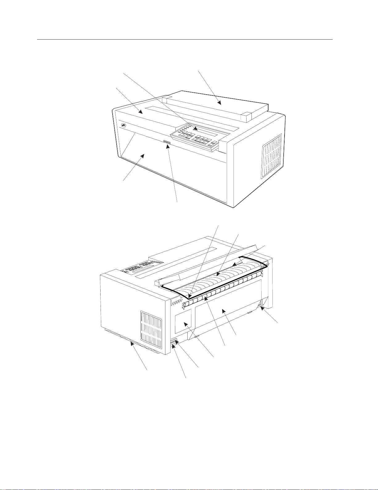
Locations
Refer to the following illustrations to familiarize yourself with the 4247 Printer:
Operator Panel
Top Cover
FrontTractor Cover
Manual Sheet FeedTray Release
Acoustic Cover
E61A3141
Wire Forms Guide
Acoustic Mat
Push Tractor Paper Slot
Automatic Sheet Feeder (ASF) Cover
Rear Tractor Door
Information Label
Attachment Card Connector
Parallel Interface Connector
Tear Bar
Power Cord Connector
E61A3142
2 4247 Model 003 User’s Guide
Page 13
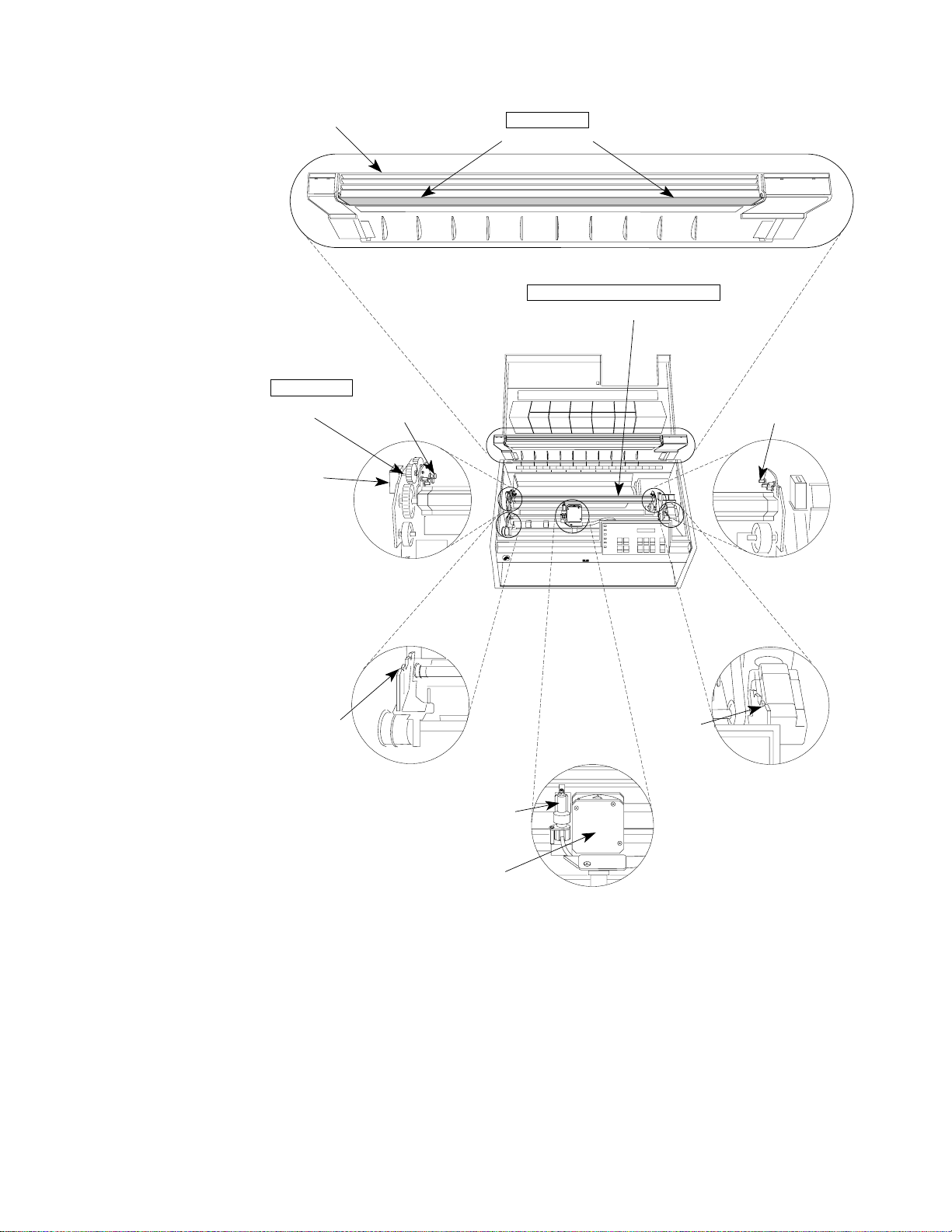
Forms Guide
ADJUSTABLE
Metal Deflector
REMOVE FOR R EAR PULL PATH
Paper Bail
ADJUSTABLE
Push-Pull
Selector
Tractor
Electrical
Connector
Ribbon
Mount
Rear
Tractor
Mounting
Pins
Ribbon
Lift
Assembly
Ribbon
Mount
Rear
Tractor
Mounting
Pins
Print
Head
Chapter 1. Getting Started 3
Page 14
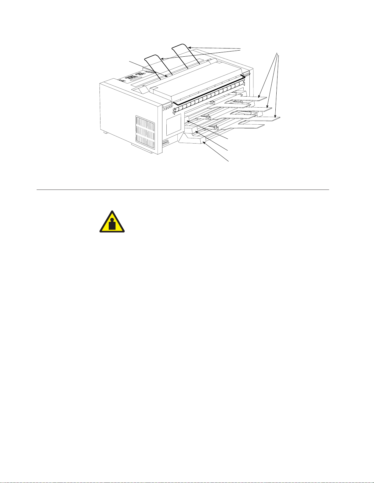
Stacker
Unpacking the Printer
ASF Bin 1
ASF Bin 2
ASF Bin 3
Optional ASF with Optional Bins
Paper Supports
e61a0050
CAUTION:
<80> This assembly weighs between 18 kg (39.7 lbs) and 32 kg (70.5 lbs). If the
entire assembly must be lifted, use two or more persons.
1. Review the following list of contents as you unpack the shipping container.
Contact your point of purchase if any items are missing.
h Printer
h One forms tractor (and optional second tractor)
h Ribbon cartridge
h Documentation
h Attachment card (if ordered - do not remove from protective package)
h Operator panel overlays
h Printer driver diskette
h Power cord
h Interface cable (if ordered)
h Wire forms guide
h Twinaxial V-connector (if twinax attachment was ordered)
4 4247 Model 003 User’s Guide
Page 15
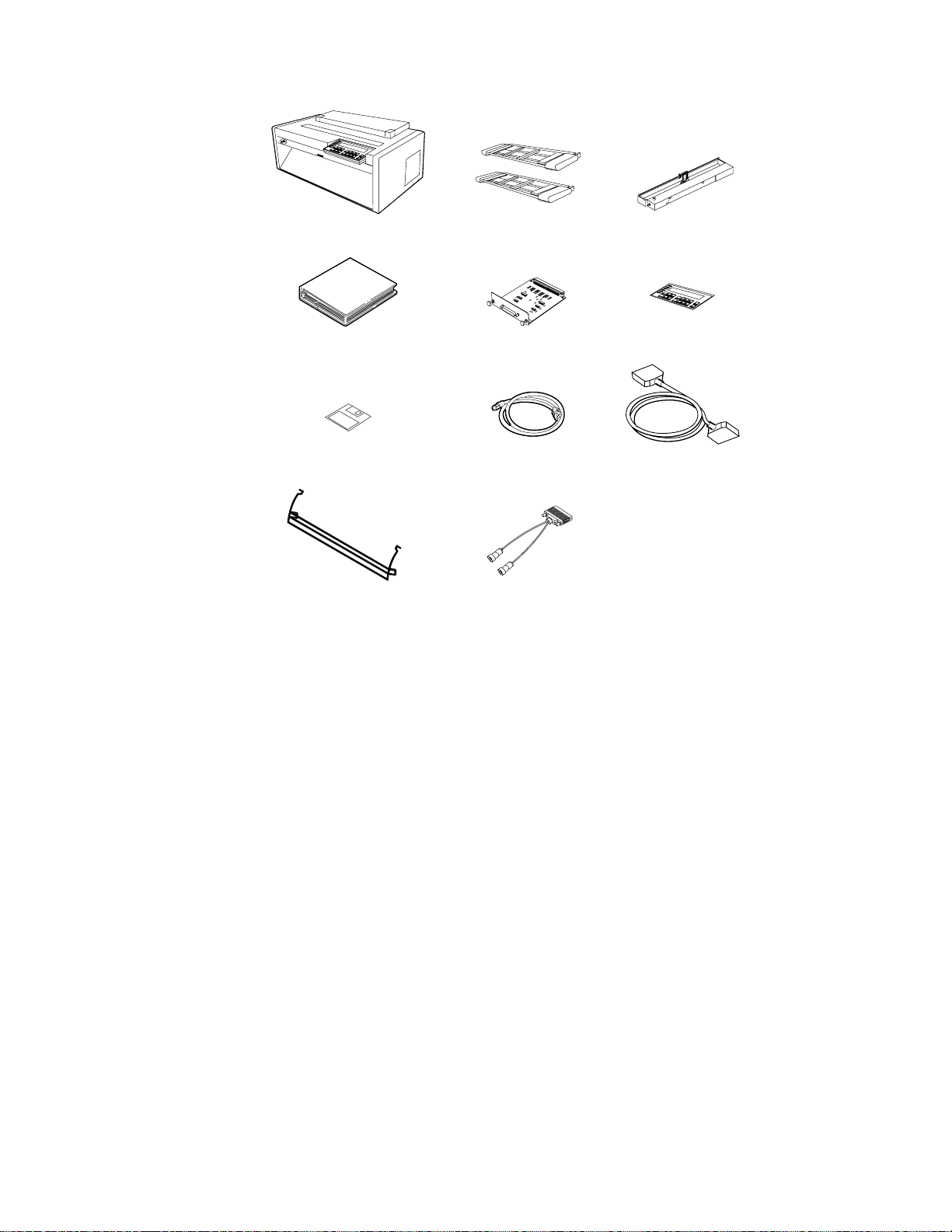
(2nd tractor is optional)
Forms TractorPrinter
Documentation
Printer Driver Diskette
Wire Forms Guide
Figure 1. Contents of Shipping Container
Attachment Card
Power Cord
Twinaxial connector
(if ordered)
Ribbon Cartridge
Operator Panel Overlay
Interface Cable(s)
E61A3138
Additionally, you can order the following options (not pictured here). Contact
your IBM marketing representative.
v Automatic Sheet Feeder - Allows feeding of envelopes or single sheets of
paper from as many as three additional cut-sheet paper trays
v Printer Stand - Provides adequate printer support, and especially helpful
when using the Dual Push forms path
v Network Print Server - Provides for ethernet 10Base2, ethernet 10BaseT,
token ring media type 1, or token ring media type 3 connectivity when
attached to the parallel interface at the rear of the printer
2. After opening the shipping container, have another person help you remove the
printer and place it on a table or the optional printer stand. If you select a table
as the permanent location, ensure:
v You have access to both the front and the rear of the printer.
v The table you select is sturdy enough to support the weight of the printer,
and firm enough to contain the action of the printer movement. To meet this
criteria, IBM recommends the optional printer stand which is available from
your IBM marketing representative.
3. Remove the remainder of the contents from the shipping container. (See
Appendix A, “Printer Specifications” for dimensions of the table or printer
stand surface and the clearances required around the printer.)
4. If you have not already done so, remove the plastic bag from the printer.
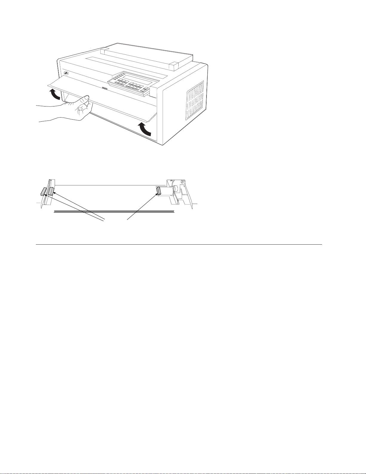
5. Lift the bottom edge of the front tractor cover into the open position.
Chapter 1. Getting Started 5
Page 16
E61A5003
6. Remove the three plastic shipping blocks (packing) from each side in the front
tractor area.
Packing
Figure 2. Front Tractor Packing
Handling Attachment Card
Attention: Do not remove the attachment card from the protective package until
instructed to do so.
Static electricity, though harmless to you, can damage sensitive attachment-card
components. Use the information in this section to avoid damaging an attachment
card.
v Limit your movement. Your movement can create static electricity that, when
released to the attachment card, can damage the electronic components on the
attachment card. Sliding your foot across carpeting is an example of how you
create unwanted static electricity.
v Handle the attachment card only by the edges and prevent others from making
direct contact with it.
v Before removing the attachment card from the protective package, ground the
package to exposed metal at the back of the printer. This will release any static
charge that may have developed on the package or on your body. Hold the
package against the metal for at least two seconds.
v When you are instructed, remove the attachment card and install it directly into
the attachment card slot without setting it down. If you have removed the
attachment card from the protective package and cannot immediately insert it in
the printer, place the protective package on a flat surface, and set the attachment
card on top of the protective package.
e61a0051
6 4247 Model 003 User’s Guide
Page 17
Installing Optional Attachment Card
Use this procedure if you received an optional attachment card with your printer.
Do not remove the attachment card from the protective package until you:
v Read the information in “Handling Attachment Card” on page 6
v Are instructed to remove the card from the protective package
The 4247 printer arrived with a parallel interface port permanently installed at the
rear of the printer. You can install an optional attachment card, positioned above
the parallel port.
1. Ensure the printer is powered off (O).
2. Open the shipping box that contains the attachment card and remove only the
screwdriver.
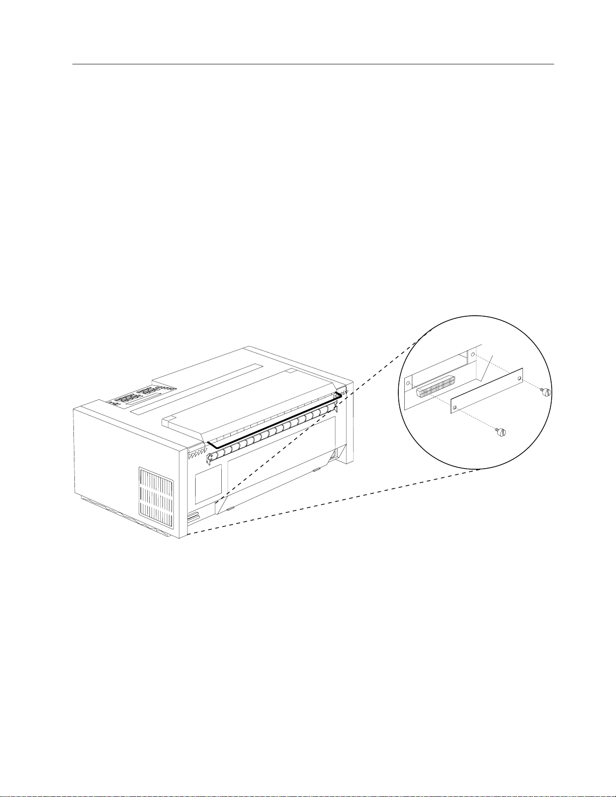
3. From above the parallel port at the rear of the printer, use the screwdriver to
remove the two screws to remove the plate that covers the attachment card slot.
These screws are not captive, and will fall away from the plate. Retain the plate
and screws if you anticipate future operation of the printer with no attachment
card installed in the slot.
Figure 3. Removing Attachment Card Cover Plate - Rear of Printer
4. Use the information in “Handling Attachment Card” on page 6 as you remove
the attachment card from its shipping box and from the protective package.
5. Position the attachment card to align with the rails of the slot. Slide the card
into place, and press against the plate of the card to ensure good physical
contact.
e61a6002
Chapter 1. Getting Started 7
Page 18
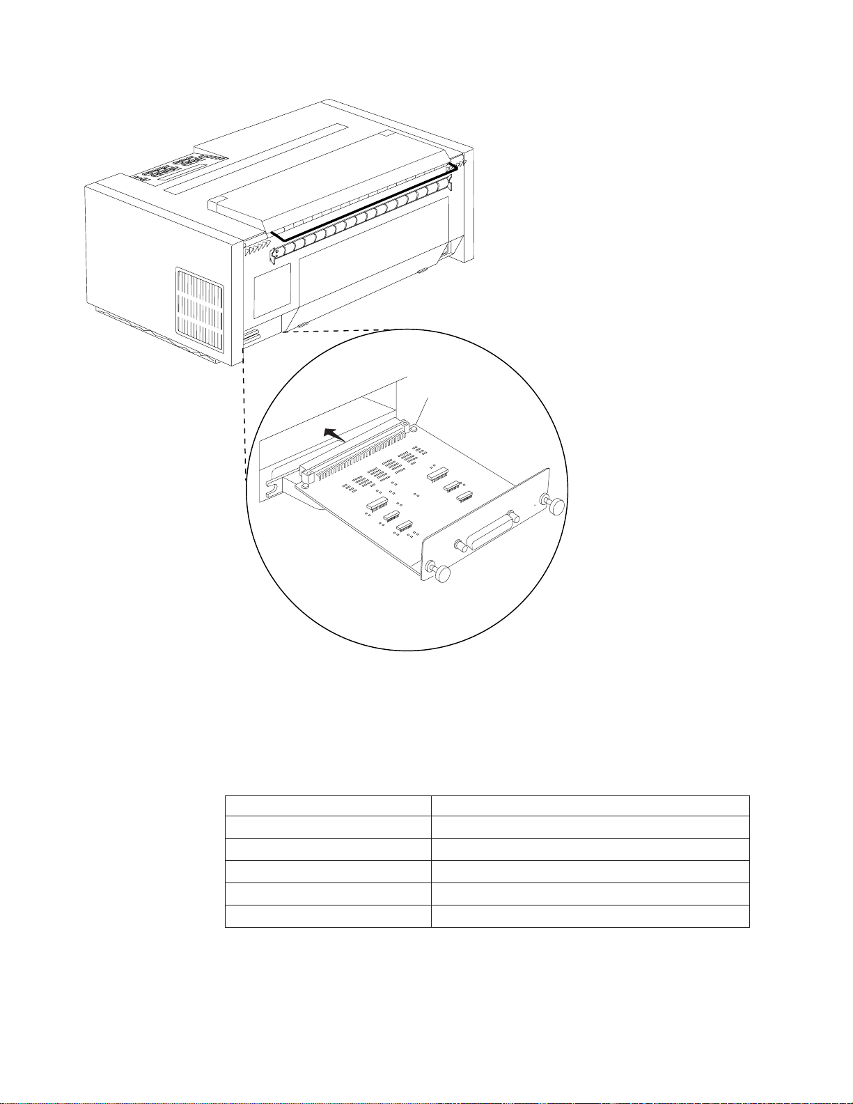
Figure 4. Installing Attachment Card
6. Press and turn the screws clockwise to tighten and secure the attachment card
in the printer. You may want to use the screwdriver to complete this task.
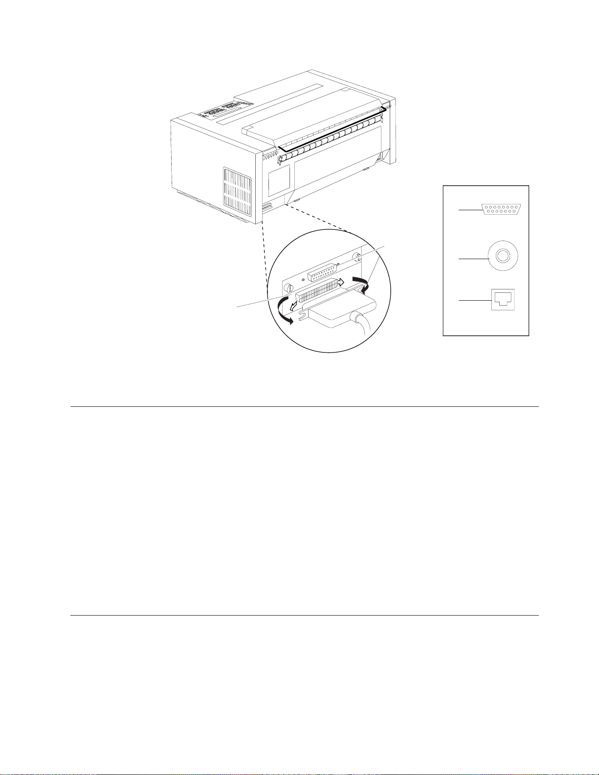
7. Identify the attachment card in the printer by comparing the plug on the
attachment card to Figure 5 on page 9 and Table 1.
Table 1. Attachment Card Identification
Item Number in Drawing Connector Type
1 Parallel (permanently installed)
2 Serial (25-pin D-shell connector)
3 Twinax (15-pin D-shell connector)
4 Coax (BNC connector)
5 Ethernet LAN (RJ45 connector)
e61a3143
8 4247 Model 003 User’s Guide
Page 19
3
2
4
1
Figure 5. Connector Types - Rear of Printer
5
Additional Installation Information For LAN Attachment Card
The LAN attachment card utilizes the AXIS 5400 Network Print Server. The
attachment card connects directly to the printer parallel port.
If you are installing a LAN attachment card, you need to consider the following
additional information.
v Prior to installing the LAN card into the printer, you must ensure access for the
card by pushing aside the parallel-connector retaining clips.
v As you install a LAN attachment card, you must apply additional pressure to
the handle (located on the card) to completely seat the card. First press on the
left side, then the right side of the handle. You are seating two connectors as you
install this card.
v With the installation of a LAN attachment card, you can not install the parallel
interface cable. The LAN attachment card uses the parallel interface port. To
learn more about installing this card, see “LAN Attachment” on page 30.
e61a6000
Installing Operator Panel Overlay
You received two overlays with your printer that are similar in appearance. You
will affix only one overlay to the operator panel. Notice the difference between the
two overlays with the Enter key, the Return key, and the Format Online or Online
status indicator. Compare Figure 6 on page 10 (for a printer without a twinax
attachment card) and Figure 7 on page 10 (for a printer with a twinax attachment
Chapter 1. Getting Started 9
Page 20
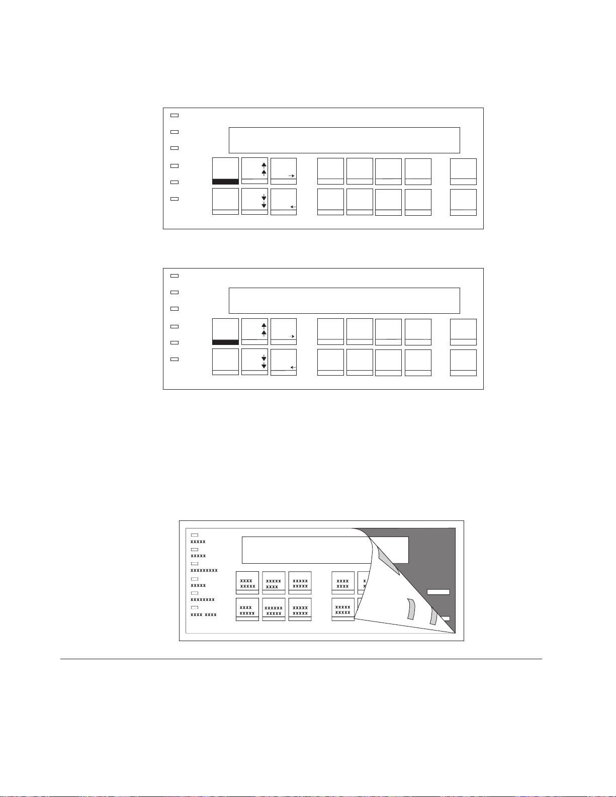
card) to determine the required overlay for your printer, and perform the following
steps to install the correct overlay.
Power
Ready
Processing
Micro
Format/Online
Attention
Unit Check
Menu
Quit
Scroll
Micro
Scroll
PA1
Enter
PA2
Return
Figure 6. 4247 Printer Operator Panel (All Printers Without Twinax Attachment)
Power
Ready
Processing
Online
Attention
Unit Check
Menu
Quit
Micro
Scroll
Micro
Scroll
Enter
Display
Address
Return
Hex
Print
Park/
Path
Hex
Print
Park/
Path
Line
Feed
Load/
Eject
Line
Feed
Load/
Eject
Form
Feed
Set Top
of Form
Form
Feed
Set Top
of Form
Start Cancel
Stop
Start Cancel
Stop
Print
Test
Print
Test
E61A5079
Figure 7. 4247 Printer Operator Panel (Printer With Twinax Attachment)
1. Remove the paper backing from the reverse side of the operator panel overlay.
2. Align the bottom of the overlay and align both sides. Ensure that the placement
you choose for the overlay will allow free movement of the operator panel
keys.
3. After being satisfied with the placement, press the overlay in place starting at
the bottom below the keys, and continue working upwards until the overlay is
pressed into place.
Installing Wire Forms Guide
E61A5075
E61A5006
Open the acoustic cover and insert one end of the wire forms guide into a hinge
block. Compress the wire forms guide and insert the other end into the other hinge
block.
10 4247 Model 003 User’s Guide
Page 21
Hinge Blocks
Note: Your wire forms guide may appear different than the one pictured in 11.
Acoustic Cover
Wire Forms Guide
Figure 8. Installing Wire Forms Guide
This forms guide will be used for forms stacking in the front push and rear push
forms paths.
Installing Ribbon Cartridge
Attention: IBM recommends that you use an IBM ribbon cartridge. To order
ribbon cartridges, contact your place of printer purchase or call Lexmark at
1-800-438-2468.
To install the ribbon cartridge, follow these steps:
1. Remove the ribbon cartridge from the package. Locate the ribbon guide, snap
arm, ribbon advance knob, and the ribbon mounting pins.
E61A5063
Ribbon Advance
Knob
Ribbon Guide
Snap Arm
e61a0220
Ribbon Mounting Pins
Chapter 1. Getting Started 11
Page 22
2. Turn the ribbon advance knob in the direction of the arrow to take up any
slack in the ribbon. If the ribbon does not move, contact your place of ribbon
purchase to replace the ribbon cartridge.
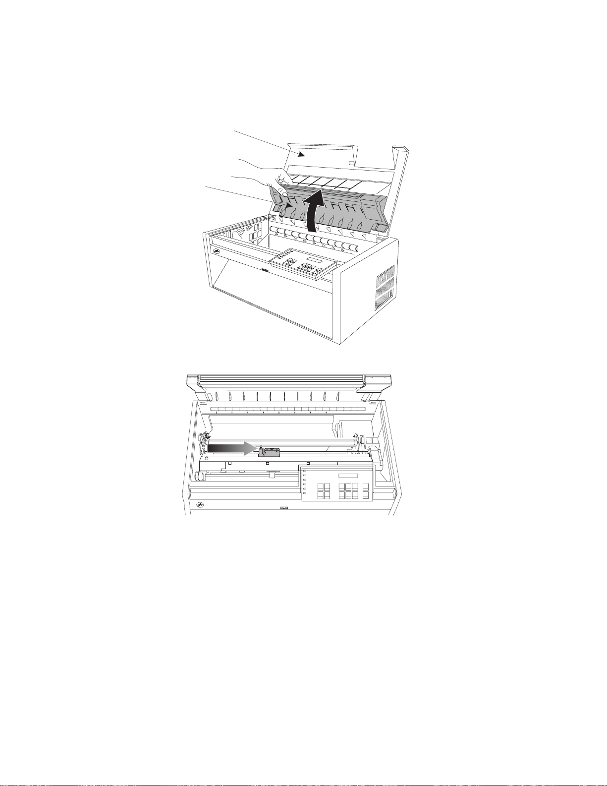
3. Open the top cover and the forms guide.
Top Cover
Forms Guide
e61a1311
4. Slide the printhead to the center of the printer.
e61a5310
5. Snap the right ribbon mounting pin into place.
6. Position the ribbon guide over the printhead.
7. Turn the ribbon advance knob to take up any slack in the ribbon.
8. With the snap arm raised higher than the ribbon lift assembly, insert the
ribbon guide between the ribbon shield and the printhead. Position the snap
arm with the small lever up onto the ribbon lift assembly. Push the snap arm
down onto the ribbon lift assembly until it snaps into place.
12 4247 Model 003 User’s Guide
Page 23
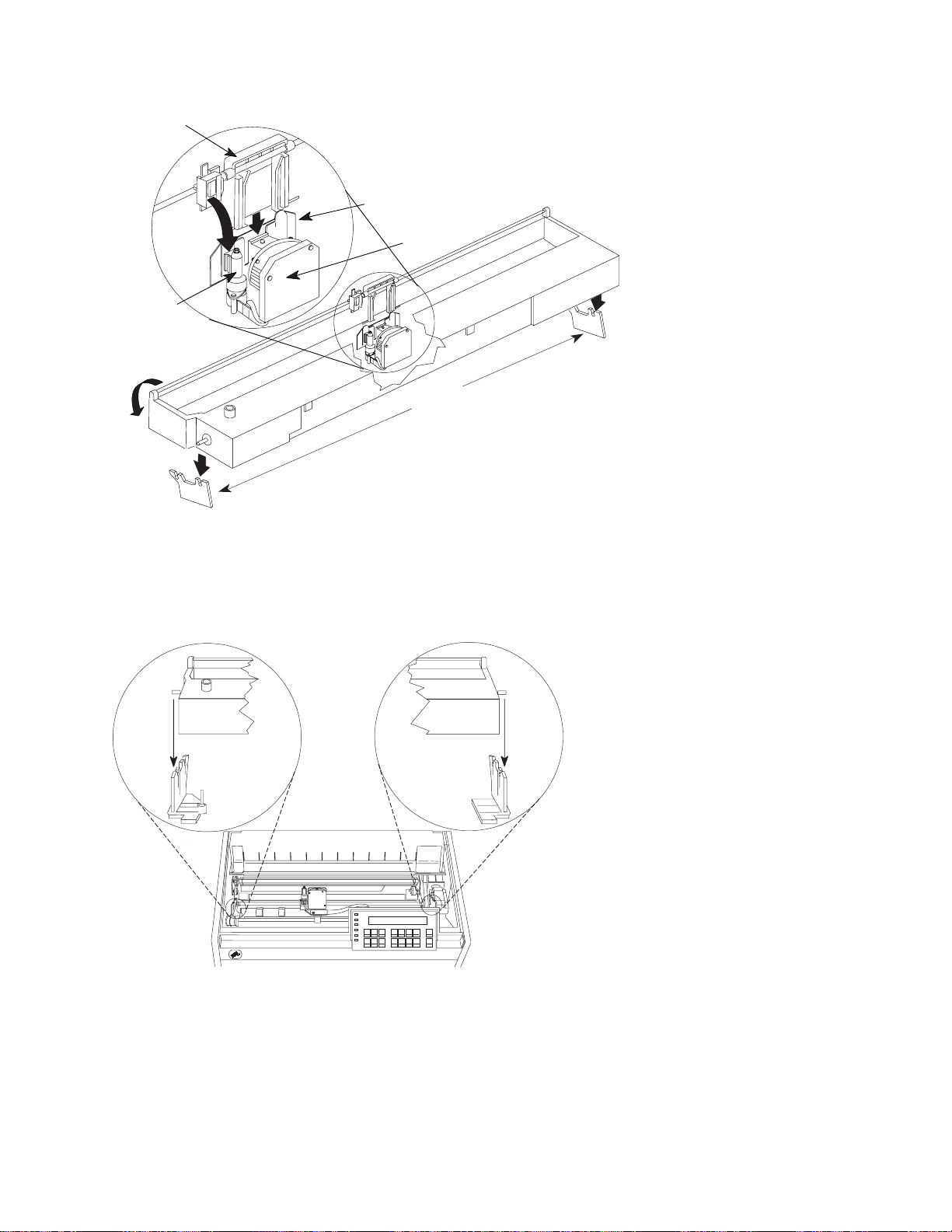
Ribbon Guide
Ribbon Lift
Assembly
Figure 9. Installing Ribbon Cartridge
9. Align the ribbon mounting pins on the left and right side of the ribbon
cartridge with the slots in the cartridge supports. Snap the ribbon cartridge
down into place.
Ribbon Shield
Printhead
Cartridge
Supports
e61a1227
Figure 10. Aligning Ribbon Cartridge Pins
10. Turn the ribbon advance knob again in the direction of the arrow to take up
any slack in the ribbon, as you slide the printhead back and forth to ensure
that the ribbon guide runs freely along the ribbon.
11. If the ribbon is not running freely, or to ensure that you have installed the
ribbon cartridge correctly, check that:
E61A5018
Chapter 1. Getting Started 13
Page 24
a. The left and right ribbon mounting pins are securely snapped into the
cartridge supports.
b. There are no twists or folds in the ribbon.
c. The ribbon is not catching on the printhead.
d. The ribbon moves when you turn the ribbon advance knob in the direction
of the arrow. If the ribbon does not move, replace the ribbon cartridge.
Contact your place of ribbon cartridge purchase if you believe that the
ribbon is faulty.
12. Close the forms guide and the top cover.
Installing Forms Tractor
For continuous forms printing, the forms tractor can be installed in the Front Push,
Rear Push, or Rear Pull positions. In combination with a second forms tractor, you
also can have Dual Push and Push-Pull positions. Manual sheet feed (cut-sheet
forms) is available at all times although its use is not recommended in conjunction
with the Rear Pull or Push-Pull forms paths. For more information on these paths,
see Chapter 17, “Setting Up Forms Paths”.
This procedure is based on the assumption that the forms tractor will be mounted
in the Front Push position.
Note: Your printer comes with one forms tractor. If you ordered a second optional
tractor, after completing this chapter refer to Chapter 17, “Setting Up Forms
Paths” for installing the second tractor.
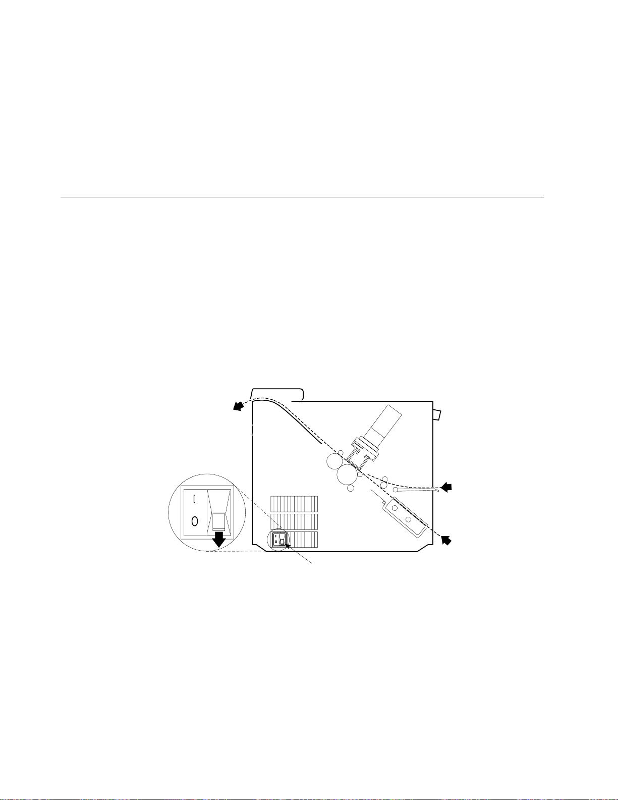
Paper Exit Front Push and
Manual Sheet F eed
Power Switch
This illustration shows the front push forms path from the left side of the printer.
Installing Forms Tractor in Front Push Position
Note: Ensure that the printer is powered off (O) to perform this procedure.
Manual Sheet F eed
Front Push
14 4247 Model 003 User’s Guide
Page 25
1. The front tractor cover should be in the open position.
E61A5003
2. Open the hinged gear protector cover by rotating it down out of the way.
G ear Protector C over
Chapter 1. Getting Started 15
Page 26
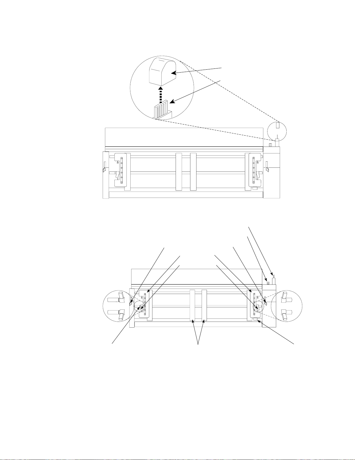
3. Remove the black protective cap (connector tab cap) from the electrical
connector located on the forms tractor.
Connector Tab Cap
Electrical Connector Tab
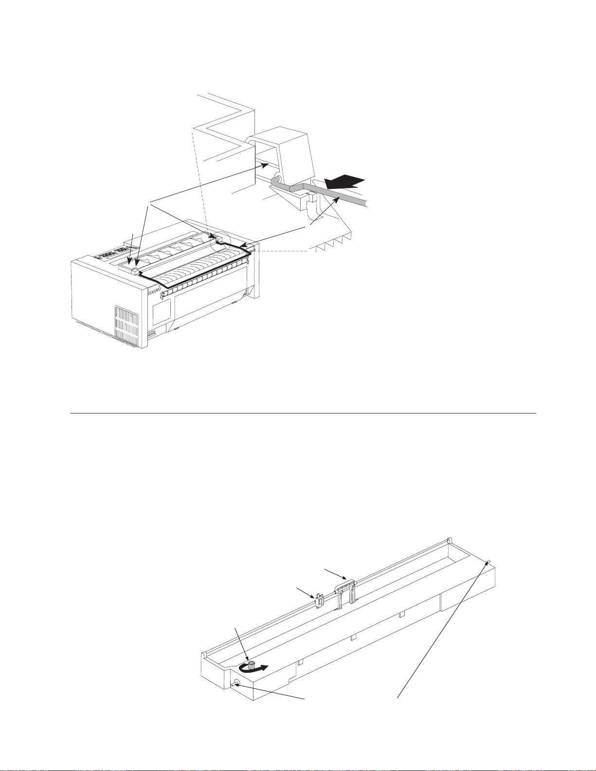
4. Stand facing the front of the printer. Hold the forms tractor with the tractor
doors toward you and the electrical connector tab on the right.
Electrical Connector Tab
Drive Gear
Tractor Unit Release Lever s
Tractor Doors
Locking Levers
Unlocked
Locked
Left Tractor
Alignment Mark
Spacers
Forms Jam Sensor
Unlocked
Locked
5. With both hands supporting the round tractor shaft, gently push the forms
tractor upward until
a. The forms tractor clicks on both sides
b. Both forms tractor release levers are in the locked (up) position
c. The electrical connector tab is fully seated in the connector
d. The bottom of the forms tractor is level with (same amount of space from)
the base of the printer
16 4247 Model 003 User’s Guide
Page 27
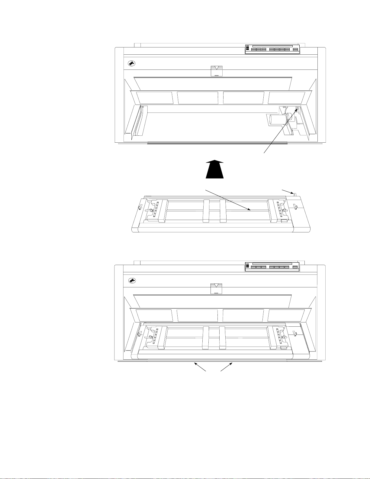
Front Tractor Electrical C onnector
Round Tractor Shaft
Electrical C onnector Tab
Connecting Power Cord
Base
Chapter 1. Getting Started 17
Page 28
DANGER
<1-30> The construction of this printer provides extra protection against the
risk of electrical shock by grounding appropriate metal parts. The extra
protection may not function unless the power cord is connected to a
properly-grounded outlet. This printer has a grounding-type (3-wire) power
cord because grounding is necessary. It is the responsibility of the customer
to the person installing the printer to connect it to a properly-grounded
outlet. Seek professional assistance before using an adapter or extension cord;
such a device could interrupt the grounding circuit.
If this printer is connected to an outlet that has been incorrectly connected to
the building wiring, serious electric shock could result.
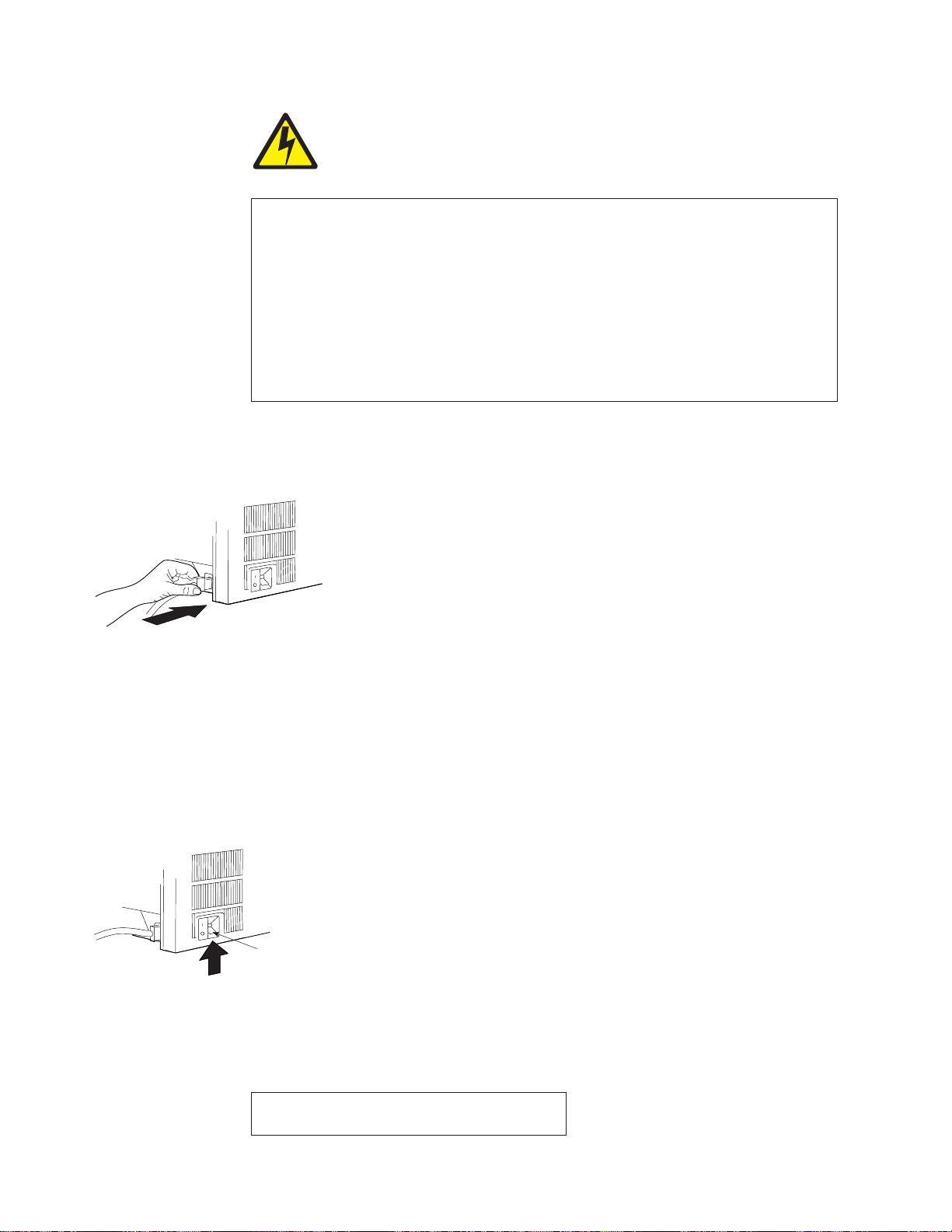
1. The connector for the power cord is located at the rear of the printer. Connect
the power cord to the power connector on the printer. Press firmly to ensure
that the plug is securely seated.
e61a0010
Figure 11. Power Connector Location, Adjacent to Power Switch (View from Rear of Printer)
2. Plug the other end of the power cord into a properly-grounded electrical
receptacle.
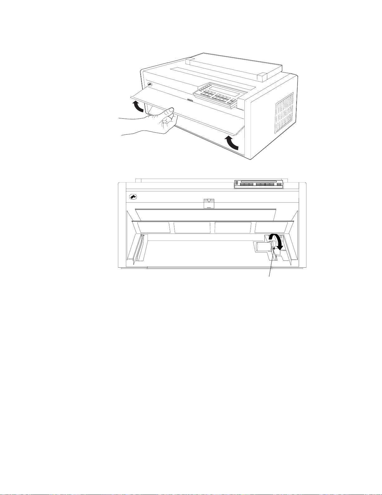
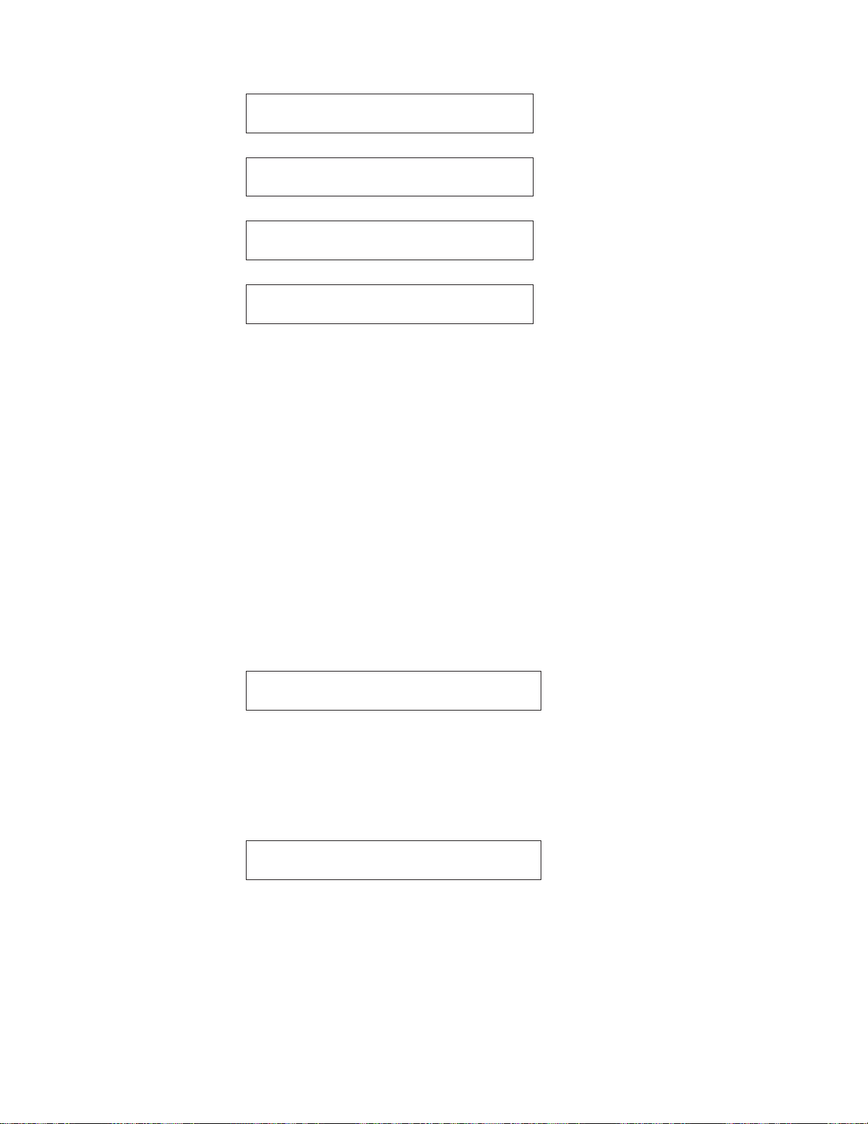
Powering On Printer
The power switch is located on the lower left side of the printer, in the area into
which you plugged the power cord.
1. Power on the printer by moving the power switch to the On (|) position.
Power Switch
Figure 12. Powering On Printer
2. Wait until the message IBM 4247 appears, all segments (or character elements)
of the LCD on the operator panel display are lighted, and DIAGNOSTICS IN
PROGRESS appears, then is replaced by one of the following Ready messages.
READY <A>
Twinax Front
18 4247 Model 003 User’s Guide
Page 29
READY <A>
Coax Front
READY <A>
Parallel Front
READY <A>
Serial Front
READY <A>
LAN Front
For twinax or coax attachment:
The printer has not been attached to a computer yet. Within the first minute
after power-on, 015 COMMUNICATIONS CHECK will appear in the display. Press
Stop to silence the alarm.
Note: If the printer does not show the correct display sequence (that is, it does
not complete initialization with a Ready message), go to the status code
section of Status Codes and Messages. Follow the instructions for the
status code shown on the display panel.
Changing Display Language (From English)
The printer is delivered with English as the default language. Follow this
procedure to change the language in which messages and menu items will appear
in the operator panel display.
1. Press Menu to enter configuration.
2. Press Scroll↑ or Scroll↓ until the printer displays:
CONFIGURATION MENU
Display Language
3. Press Enter to display the current value.
4. Press Scroll↑ or Scroll↓ until the language you want is displayed.
5. Press Enter. An asterisk (*) will be displayed in front of the selected value.
6. Press Return to return to the Configuration Menu.
7. Press Start. The printer displays:
Press ENTER to Save a Custom Set
Press START to Not Save in a Set
8. Choose between one of these options:
v If you want to use the selected display language as the printer default for
this session only (the printer will use the existing defaults the next time it is
powered on), press Start. The printer will exit the menu and become ready.
v OR
v If you want to keep the selected display language as the printer default,
press Enter. The printer displays:
Chapter 1. Getting Started 19
Page 30
Save Current Values
Custom Set A
9. Press Enter.
10. Press Start again. The printer will exit the menu and become ready.
Loading Forms in Front Push Tractors
Note: Before starting this procedure, ensure you have single-part, continuous
forms that are at least 210 mm (8.27 in.) wide. You need at least this size
forms to create an offline printout, which will test printer operation.
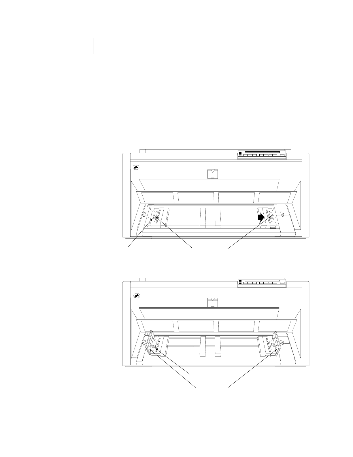
1. Unlock the locking levers on the tractors. Move the right tractor to the
extreme right.
2. Move the left tractor to the tractor alignment mark.
Alignment Mark
Locking Levers
3. Lock the left locking lever.
4. Open both of the tractor doors.
Left Locking Lever
Tractor Doors
5. Put the left tractor holes of the form over the left tractor pins. Close the
left tractor door.
6. Move the right tractor until the right tractor holes of the form fit on the
right tractor pins. Ensure that the forms go under the forms jam sensor
20 4247 Model 003 User’s Guide
Page 31

and that the forms are straight.
7. Close the right tractor door.
Top of Fo rm
Paper Under Forms Jam Sensor
8. If necessary, slide the right tractor to the right side of the printer to
remove the slack in the form. If the forms are too tight, slide the right
tractor away from the right side of the printer. Ensure that the tractor
pins are centered in the tractor holes.
Left Margin
Right Margin
Correct
Left Margin
Right Margin
Incorrect
9. While holding the right tractor in place, lock the right locking lever.
Chapter 1. Getting Started 21
Page 32

10. Move the spacers along the tractor bar to support the width of the
form.
11. Close the front tractor cover.
12. Press Stop to make the printer not ready.
13. Press Load/Eject to feed the forms.
Printing Your First Document
The Quick Reference is a popular print test that may help familiarize you with the
operator panel keys and the configuration menu you can set. The Quick Reference
printout allows you to check print quality and printer operations.
v Each key is listed with a corresponding description to the right.
v Each parameter is shown with the corresponding values you can select printed
to the right.
1. Ensure that the printer is offline. If the printer is ready, press Stop to make the
printer not ready.
2. Press Test.
Spacers
e61a5033
E61A5034
22 4247 Model 003 User’s Guide
Page 33

3. Press Scroll ↑ or Scroll ↓ until the printer displays:
4247 OPERATOR PRINT TESTS
Quick Reference
4. Press Enter or Start to print this test. The Ready indicator comes on and
printing begins. Press Stop if you want stop the Print Test before it completes
printing.
5. Wait for the printer to stop printing and the Ready indicator to go off.
6. Press Form Feed until you can remove the printout. The printout should be
clear and readable.
YOU HAVE JUST COMPLETED A SETUP AND CHECKOUT OF THE PRINTER.
IBM recommends that you now print your printer configuration defaults. Save this
printout for future reference. You can create a printout of the printer configuration
by following these steps:
1. Press Scroll ↑ or Scroll ↓ until the printer displays:
4247 OPERATOR PRINT TESTS
Print Custom Sets
2. Press Enter or Start to print this test. See “Print Custom Sets” on page 280 for
more information about this printout.
3. To exit Print Test, press Return to make the printer not ready or Cancel/Print to
make the printer ready.
Attaching the 4247 Printer to Your Computer
This section provides specific instructions on attaching the printer to your
computer. You may want to attach the printer to more than one computer. If so,
you need to perform the steps in each appropriate section.
The attachments you have on your printer depend on what you requested at the
time you placed your order. Your printer is capable of attaching as:
v Twinax and parallel
v Coax and parallel
v Serial and parallel
v LAN only
v Parallel only
Refer to the following sections for additional information.
v For Twinax attachment, go to “Twinax Attachment”.
v For Coax attachment, go to “Coax Attachment” on page 27.
v For Parallel attachment, go to “Parallel Attachment” on page 28.
v For Serial attachment, go to “Serial Attachment” on page 29.
v For LAN attachment, go to “LAN Attachment” on page 30.
Twinax Attachment
To attach your printer using a twinax cable (not shipped with the printer), follow
these steps:
Chapter 1. Getting Started 23
Page 34

1. Before attaching the twinax cable, set the printer address. If your desired
printer address is 0, go to Step 2 on page 25. If your desired printer address is
not 0, see the following table for the valid values and follow Steps 1a through
1k on page 25 to change the value. If you do not know what to assign for the
printer address, check with your system operator.
If Desired
Address Is: Set:
0 000 Printer Address=0
1 001 Printer Address=1
2 002 Printer Address=2
3 003 Printer Address=3
4 004 Printer Address=4
5 005 Printer Address=5
6 006 Printer Address=6
Shown when Setting
Printer Address:
To set the printer address, follow these steps:
a. Power on (|) the printer.
b. Wait until the message IBM 4247 appears, all segments of the LCD on the
operator panel display are lighted, and the printer has stopped all motion.
The printer then displays:
DIAGNOSTICS IN PROGRESS
PLEASE WAIT
READY <A>
Twinax Front
and this error message is displayed:
015 COMMUNICATIONS CHECK
CHECK CABLE
c. Press Menu.
d. Press Scroll ↑ or Scroll ↓ until the printer displays:
CONFIGURATION MENU
Twinax Configuration
e. Press Enter.
f. Press Scroll ↑ or Scroll ↓ until the printer displays:
Twinax Configuration
Printer Address
g. Press Enter. The printer displays:
Printer Address
* 000
h. Press Scroll ↑ or Scroll ↓ until the printer displays the desired address.
24 4247 Model 003 User’s Guide
Page 35

i. Press Enter to set the address. An asterisk (*) appears beside the address.
j. The 4247 printer supports several emulation modes. The default mode is
native 4247. However, if your computer system is not at a software level that
recognizes printer type 4247, change the printer emulation to 4230, 4224, or
4214, depending upon your requirements.
To do this, press Return. The printer displays:
Twinax Configuration
Printer Address
Press Scroll ↑ or Scroll ↓ until the printer displays:
Twinax Configuration
Emulation Mode
Press Enter. The printer displays:
Emulation Mode
*4247
Using the Scroll ↑ or Scroll ↓ key, scroll to the desired emulation mode, then
press Enter. An asterisk (*) will be displayed in front of the selected value.
k. Press Start.
The printer displays:
015 COMMUNICATIONS CHECK
CHECK CABLE
2. The power switch is located on the lower left side of the printer. Ensure the
printer is powered off (O) and the power cable is unplugged.
DANGER
<1-14> Switch off printer power and unplug the printer power cord before
connecting or disconnecting a communication port, a teleport, or any other
attachment connector.
DANGER
<1-13> Do not connect or disconnect a communication port, a teleport, or
any other connector during an electrical storm.
3. Before you connect the signal cable to the V-connector, slip a cable shield over
the end of the cable. (If you are connecting two cables, slip a cable shield over
Chapter 1. Getting Started 25
Page 36

the end of both cables.)
4. Align the two pins and the key slot in the signal cablewith the two holes and
the key in the end of the V-connector.
v Plug the signal cable into the following connector and turn the signal cable
connector clockwise until it locks into place.
Notes:
a. There is no specified “input” or “output” end to the connector. You can
b. The V-connectors are “self-terminating” and do not require you to set a
5. Insert the cable connector into the upper interface connector. Ensure that the
cable connector is securely seated. Tighten the two locking screws to hold the
cable in place.
6. Connect the power cord to the printer and the wall outlet.
7. Power on (|) the printer.
8. Wait until the message IBM 4247 appears, all segments of the LCD on the
operator panel display are lighted, and the printer has stopped all motion. The
printer then displays:
DIAGNOSTICS IN PROGRESS
PLEASE WAIT
26 4247 Model 003 User’s Guide
attach a signal cable to either end or both ends of the connector. You can
connect another device to the unused end of the connector.
“terminator switch” which might be found on other printer products.
Page 37

READY <A>
Twinax Front
Note: If the printer does not show the correct display sequence, go to the
status code section of Chapter 20, “Problem Solving” and follow the
instructions there for the status code shown on the display panel.
Coax Attachment
DANGER
<1-14> Switch off printer power and unplug the printer power cord before
connecting or disconnecting a communication port, a teleport, or any other
attachment connector.
DANGER
<1-13> Do not connect or disconnect a communication port, a teleport, or any
other connector during an electrical storm.
To attach a coax cable (not shipped with the printer), follow these steps:
1. The power switch is located on the lower left side of the printer. Ensure that
the printer is powered off (O) and the power cable is unplugged.
2. Attach one end of the signal cable to the upper interface connector on the back
of the printer.
3. Turn the signal cable connector clockwise until the cable locks in place.
4. Connect the power cord to the printer and to the electrical outlet.
5. Power on (|) the printer.
6. Wait until the message IBM 4247 appears, all segments of the LCD on the
operator panel display are lighted, and the printer has stopped all motion. The
printer then displays:
DIAGNOSTICS IN PROGRESS
PLEASE WAIT
READY <A>
Coax Front
Note: If the printer does not show the correct display sequence, go to the
status code section of Chapter 20, “Problem Solving”. and follow the
instructions there for the status code shown on the display panel.
Chapter 1. Getting Started 27
Page 38

Parallel Attachment
DANGER
<1-14> Switch off printer power and unplug the printer power cord before
connecting or disconnecting a communication port, a teleport, or any other
attachment connector.
DANGER
<1-13> Do not connect or disconnect a communication port, a teleport, or any
other connector during an electrical storm.
To attach a parallel cable:
1. The power switch is located on the lower left side of the printer. Power off (O)
the printer and unplug the power cable.
2. Standing behind the printer, push the parallel interface cable into the lower
interface connector on the back of the printer in the lower left corner.
3. Push the clips at each end of the connector into the notches on the parallel
cable.
4. Refer to your computer system documentation for information on attaching
the cable to your computer.
5. After you attach the computer end of the interface cable, connect the power
cord to the printer and to the electrical outlet.
6. Power on (|) the printer.
7. Wait until the message IBM 4247 appears, all segments of the LCD on the
operator panel display are lighted, and the printer has stopped all motion.
The printer then displays:
DIAGNOSTICS IN PROGRESS
PLEASE WAIT
READY <A>
xxxxxx Front
8. Press Menu.
9. Press Scroll ↑ or Scroll ↓ until the printer displays:
CONFIGURATION MENU
Attachment
10. Press Enter to display the current value.
28 4247 Model 003 User’s Guide
*Where xxxxxx (depending on your attachment) can be the default twinax or
coax.
Page 39

11. Press Scroll ↑ or Scroll ↓ until the printer displays:
Attachment
Parallel
12. Press Enter. An asterisk (*) will be displayed in front of the selected value.
13. Press Start. The printer displays:
Press ENTER to Save a Custom Set
Press START to Not Save in a Set
14. If you want to use the parallel attachment for this session only (the printer
will use the default attachment the next time it is powered on), press Start
again. The printer will exit the menu and become ready.
15. To keep the parallel attachment as the default power-on attachment, press
Enter. The printer will display
Save Current Values
Custom Set A
16. Press Enter.
17. Press Start again. The printer will exit the menu and become ready.
Notes:
1. See Chapter 4, “Configuration Storage” on page 67 for more information on
saving configuration information in custom sets, including information about
specifying the default custom set to use when the printer is powered on.
(Unless you specify otherwise, the printer will power on using the custom set
configuration values it was using when it was last powered off.)
2. If the printer does not show the correct display sequence, go to the status code
section of Chapter 20, “Problem Solving”.
Serial Attachment
DANGER
<1-14> Switch off printer power and unplug the printer power cord before
connecting or disconnecting a communication port, a teleport, or any other
attachment connector.
DANGER
<1-13> Do not connect or disconnect a communication port, a teleport, or any
other connector during an electrical storm.
To attach a serial cable, follow these steps:
Chapter 1. Getting Started 29
Page 40

1. The power switch is located on the lower left side of the printer. Ensure that
the printer is powered off (O) and the power cable is unplugged.
2. Attach one end of the signal cable to the upper interface connector on the back
of the printer.
3. Tighten the two locking screws to secure the cable.
4. Connect the power cord to the printer and to the electrical outlet.
5. Power on (|) the printer.
6. Wait until the message IBM 4247 appears, all segments of the LCD on the
operator panel display are lighted, and the printer has stopped all motion. The
printer then displays:
DIAGNOSTICS IN PROGRESS
PLEASE WAIT
READY <A>
Serial Front
Note: If the printer does not show the correct display sequence, go to the
status code section of Chapter 20, “Problem Solving”. and follow the
instructions there for the status code shown on the display panel.
LAN Attachment
The LAN attachment card contains an AXIS 5400 Network Print Server, and has
these features:
v Connects directly to the printer parallel port
v Connects to 10 Mbps ethernet or 100 Mbps Fast Ethernet networks
v Contains autosensing circuitry that detects the speed of your local network and
matches the LAN data communication speed to network speed of 10 Mbps or
100 Mbps
The LAN attachment card receives data from your network and passes it to the
printer through the parallel port of the printer. This allows you to use the parallel
configuration menu items. You should keep the Parallel Interface Type menu item
set to PC Parallel, which is the factory default setting.
The 4247 LAN card is similar to the AXIS 5400 Network Print Server with the
following exceptions:
v Different physical appearance
v The AXIS 5400 uses an external power source. The 4247 LAN card is powered
by the printer.
v While both contain an integral network indicator LED, a test button, and an
ethernet connector, the 4247 LAN card does not include a power-on indicator
LED. Power-on status is indicated by a READY LAN or NOT READY LAN message.
Verify LAN-Attachment-Card to Parallel-Interface Connection
Before you connect the printer to a network, verify the LAN attachment
card-to-parallel port connection by creating an offline, test page printout.
1. Ensure that forms are loaded in the forms path. You will generate printed
output in the next step.
30 4247 Model 003 User’s Guide
Page 41

2. Locate the Test button, the Network indicator light, and the label that bears the
node address, all located on the LAN attachment card case.
3. Ensure the printer is powered on (|) and READY LAN appears on the display.
Press Start if the printer is not ready.
4. With the printer powered on (|), press the test button. The printer will produce
printed output depending upon your action:
a. After the indicator light begins to flash, press and release the test button to
print out configuration highlights.
b. Press and hold the Test button on the LAN attachment card until the
Network indicator LED stops flashing. Because the button is recessed, use a
tool if you cannot depress the Test button using your finger.
The test button also can be used to reset the LAN attachment settings to the
default or factory settings. Refer to the User’s Manual on the "AXIS Online CD"
for more information.
Create a test page printout to verify that the parallel interface will allow
communication. The test page printout includes AXIS 5400 Network Print Server
information.
Attaching LAN Signal Cable to Printer
DANGER
<1-14> Switch off printer power and unplug the printer power cord before
connecting or disconnecting a communication port, a teleport, or any other
attachment connector.
DANGER
<1-13> Do not connect or disconnect a communication port, a teleport, or any
other connector during an electrical storm.
Note: Category 5, twisted pair cable must be used if connecting to a 100 Mbps
Fast Ethernet network.
To attach a LAN cable (not shipped with the printer), follow these steps:
1. The power switch is located on the lower left side of the printer. Ensure that
the printer is powered off (O) and the power cable is unplugged.
2. Attach one end of the signal cable to the interface connector on the back of the
printer.
3. Connect the power cord to the printer and to the electrical outlet.
4. Power on (|) the printer.
5. Wait until the message IBM 4247 appears, all segments of the LCD on the
operator panel display are lighted, and the printer has stopped all motion. The
printer then displays:
Chapter 1. Getting Started 31
Page 42

DIAGNOSTICS IN PROGRESS
PLEASE WAIT
READY <A>
LAN Front
Note: If the printer does not show the correct display sequence, go to the
status code section of Chapter 20, “Problem Solving”. Follow the
instructions there for the status code shown on the display panel.
Review the AXIS 5400 User’s Manual, located on the AXIS Online CD that shipped
with your printer, to complete the installation and integration of the LAN
attachment. User information about this attachment card is not provided in this
Guide, but is provided in the User’s Manual of the "AXIS Online CD."
About ASCII Printer Drivers
Note: These printer drivers support only the ASCII attachment for your printer.
The possible ASCII attachments are parallel, serial, and LAN.
The 4247 printer is supported in the following operating systems or environments:
®
v AIX
v OS/400
v OS/2
v Windows
version 3.2.5 and later
®
version 2.3 Host Print Transform
®
version 2.1 and later
®
version 3.1, Windows 95, Windows 98, Windows NT 3.51, and
Windows NT 4.0
For AIX Operating Systems
Use the Printer Driver Diskette shipped with your printer. The files in the AIX
subdirectory enable the user to add a 4247 printer as a printer device and add
virtual printers in three emulation modes:
v IBM 2381 Personal Printer
v IBM 4202 Proprinter III XL
v Epson FX
To use the printer driver, establish a virtual printer queue for each desired
emulation.
For OS/400 Operating Systems
Use the Printer Driver Diskette shipped with your printer. The files in the OS400
subdirectory enable the user to add a 4247 as a printer object. Support for
4247-unique commands is limited to Host Print Transform. Six new 4247
workstation customization tables are based on tables used for the 2381 Printer.
Modifications to the tables were made to support various 4247 forms handling
capabilities, fonts, and print qualities.
For OS/2 and Windows Operating Environment
Windows drivers for the 4247 are not shipped with your printer, and must be
downloaded from the web. They are found on the IBM Printing Systems web page
at http://www.printers.ibm.com.
32 4247 Model 003 User’s Guide
Page 43

4247 Drivers
Drivers are available for the following operating systems:
v Windows 3.1
v Windows 95/98
v Windows NT 3.51
v Windows NT 4.0
Other Drivers
Use one of the following drivers that is provided with your operating system.
When using these drivers, some of the 4247 advanced features will not be
selectable from the data stream. You may, however, use the operator panel to select
these features.
v IBM 2381 Personal Printer
v IBM 4202 Proprinter III XL
v Epson FX 1050
Installing ASCII Printer Drivers
The 4247 printer is supported by the following operating systems or environments:
v AIX version 3.2.5 and later
v OS/400 version 2.3 Host Print Transform
v OS/2 version 2.1 and later
v Windows version 3.1, Windows 95, Windows 98, Windows NT 3.51, and
Windows NT 4.0
AIX Driver Installation
The AIX driver files reside on a DOS-formatted diskette in the AIX subdirectory.
The files are:
license.txt
AIX printer driver license statement
4247.txt
Driver installation instructions
4247.tar
Drivers and additional information for AIX 3.2.5
ibm4247.tar
Drivers and additional information for AIX 4.1
To read the diskette, cd to the directory of choice (such as /tmp) and issue the
following commands:
# dosread -a /AIX/license.txt license.txt
# dosread -a /AIX/4247.txt 4247.txt
# dosread /AIX/4247.tar 4247.tar
# dosread /AIX/ibm4247.tar ibm4247.tar
Use the more or pg command to view the license agreement in the license.txt file,
and the installation instructions in the 4247.txt file. You must understand and agree
to the terms and conditions stated in the license.txt file before installing the AIX
driver.
OS/400 Printer Object Installation
The OS/400 printer object files reside on a DOS formatted diskette in the OS400
subdirectory. The files are:
license.txt
OS/400 printer objects license statement
Chapter 1. Getting Started 33
Page 44

read.1st
OS/400 printer object upload and installation instructions
4247.doc
Explains the use and function of the OS/400 printer objects. Read this file
before you attempt to upload either of the following .txt files
ibm4247m.txt
Source file for the 4247 workstation customization object when the 4247 is
configured with one continuous form feed or the user wants to select the
form feed method from the operator panel
ibm4247.txt
Source file for the 4247 workstation customization object when the 4247 is
configured with two continuous forms feeders
ib4247a2.txt
Source file for the 4247 workstation customization object when the 4247 is
configured for the optional Automatic Sheet Feeder (ASF) unit. Required
for use with pre-V3R1 operating systems; this object limits AS/400
selection of the 4247 ASF paper bins to two.
ib4247a3.txt
Source file for the 4247 workstation customization object when the 4247 is
configured for the optional Automatic Sheet Feeder (ASF) unit. Required
for use with V3R1 and later operating systems; this object provides AS/400
selection of all three 4247 ASF paper bins.
ib4247x2.txt
Source file for the 4247 workstation customization object when the 4247
user wants to select between one continuous forms feed or bin 1 of the
optional Automatic Sheet Feeder (ASF) unit. Required for use with
pre-V3R1 operating systems; this object limits AS/400 selection of the 4247
paper paths to two.
ib4247x3.txt
Source file for the 4247 workstation customization object when the 4247
user wants to select one continuous forms feed or bin 1 or bin 2 of the
optional Automatic Sheet Feeder (ASF) unit. Required for use with V3R1
and later operating systems; this object provides AS/400 selection of three
4247 paper paths.
Use the text editor that came with your personal computer operating system (such
as Windows 3.0 WRITE or OS/2 E) to view the license agreement in the license.txt
file and to view the read.1st and 4247.doc files.
To print the read.1st file (or any of the files), use an operating system command
such as:
copy a:\os400\read.1st lpt1:
You must understand and agree to the terms and conditions stated in the
license.txt file before installing the OS/400 printer object.
OS/2 Or Windows Printer Driver Installation
You can choose from various windows drivers.
4247 Data Stream On Windows Drivers
In addition to the drivers available on the diskette that is shipped with the 4247
printer, there are Windows drivers for the 4247 printer. These drivers must be
downloaded from the web. They are found on the IBM Printing Systems Company
web page at http://www.printers.ibm.com.
There are four drivers available, with support as follows:
34 4247 Model 003 User’s Guide
Page 45

v Windows 3.1
v Windows 95/98
v Windows NT 3.51
v Windows NT 4.0
In order to print with the euro character, the euro-capable code page must be
selected at the printer operator panel and not over-ridden by your job.
These drivers are available only in English.
These drivers support the selection of the multiple forms paths available on the
4247 with the exception of the manual feed path. That path cannot be selected by
any of the 4247 drivers. The manual feed path must be selected at the operator
panel.
In Windows 95/98 and NT, the standard WYSIWYG approach in drivers causes
your job to be sent to the printer as graphics, so that the printer can use
typographic fonts typical of PC applications. This significantly slows the printer,
since it is printing at NLQ speeds. By selecting the resident draft fonts from the
font list, this can be avoided. However, if this is done, then your job is now
tailored specifically for the 4247 printer and there may be problems printing to
other printers. The resident 4247 draft font is available in the following CPI values:
5, 6, 7.5, 8.5, 10, 12, 15, 17, 20, and PS.
OS/2 and Windows Drivers
Use one of the following drivers (not shipped with the printer) that is provided
with your operating environment. When using these drivers, some of the 4247
advanced features will not be selectable from the data stream. You may, however,
use the operator panel to select these features.
v IBM 2381 Personal Printer
v IBM 4202 Proprinter III XL
v Epson FX 1050
Completing Printer Setup
Your 4247 Printer is now ready to use with the forms tractor mounted in the Front
Push position and with the configuration parameters set to manufacturing defaults.
The exception is that you have selected new defaults for display language.
If your ordered a second optional tractor, see Chapter 17, “Setting Up Forms Paths”
for instructions on installing the second tractor in the Dual-Push, Rear Pull, or
Push-Pull position.
To select any of the other 4247 paper paths, or to change printer configuration
parameters, see:
v Chapter 2, “Understanding the Operator Panel” for information on operating the
printer,
v Chapter 3, “Checking and Changing Configuration Parameter Values” for
configuration information,
v Chapter 5, “Changing Attachment Selection” for configuration information,
v Chapter 17, “Setting Up Forms Paths” for forms loading procedures, or
v 4247 Printer Automatic Sheet Feeder Guide, SA24-4407, for information on
installing the ASF feature.
Chapter 1. Getting Started 35
Page 46

36 4247 Model 003 User’s Guide
Page 47

Chapter 2. Understanding the Operator Panel
Status Indicators.............38
Power...............38
Ready ...............38
Processing..............39
Online (Twinax) ............39
Format/Online (Coax) ..........39
Format/Online (Parallel, Serial, or LAN) . . . 39
Attention ..............39
Unit Check .............39
Display Panel..............39
Audible Alarm .............40
Custom Set In-Use Indicator.........40
Function Keys .............40
Menu...............41
Quiet ...............42
Micro↑/Scroll↑ or Micro↓/Scroll↓ ......42
Adjusting Forms...........42
Scrolling Through Categories, Parameters,
Values, and Tests ..........43
Enter (Twinax) ............43
Display Address/Return← (Twinax) .....43
Display Address Function .......43
Return Function ...........44
This chapter describes the function of the operator panel. The operator panel
contains 6 status indicators, a 2-line by 40-character display panel, 16 printer
function keys, and an audible alarm. Figure 13 illustrates the operator panel and
keys for the printer without a twinax attachment. Figure 14 on page 38 illustrates
the operator panel and keys for the printer with twinaxial (twinax) attachment.
PA1/Enter→ (Parallel, Serial, Coax, or LAN) . . 44
PA1 Function (Coax Only) .......44
Enter Function ...........44
PA2/Return (Parallel, Serial, Coax, or LAN) . . 44
PA2 Function (Coax Only) .......45
Return Function ...........45
Hex Print ..............45
Park/Path ..............46
Park Function ...........46
Path Function ...........46
Line Feed ..............46
Load/Eject .............47
Front Push and Rear Push .......47
Rear Pull .............48
Push-Pull .............48
Manual Sheet Feed ..........48
Auto Sheet Feed...........49
Form Feed..............49
Set Top of Form ............49
Start................50
Stop ................50
Cancel Print .............51
Test................51
Power
Ready
Processing
Format/Online
Attention
Unit Check
Menu
Quit
Micro
Scroll
Micro
Scroll
PA1
Enter
PA2
Return
Hex
Print
Park/
Path
Line
Feed
Load/
Eject
Form
Feed
Set Top
of Form
Start Cancel
Stop
Print
Test
E61A5079
Figure 13. 4247 Printer Operator Panel (All Printers Without Twinax Attachment)
© Copyright IBM Corp. 2002 37
Page 48

Figure 14. 4247 Printer Operator Panel (Printer With Twinax Attachment)
Status Indicators
The following status indicators appear on the operator panel:
v Power
v Ready
v Processing
v Online (Twinax)
v Format/Online (Coax)
v Attention
v Unit Check.
Power
Ready
Processing
Online
Attention
Unit Check
Menu
Quit
Micro
Scroll
Micro
Scroll
Enter
Display
Address
Return
Hex
Print
Park/
Path
Line
Feed
Load/
Eject
Form
Feed
Set Top
of Form
Start Cancel
Stop
Print
Test
E61A5075
Power
Ready
You can determine printer status by checking these indicators.
If on, the printer has power. If off, the printer does not have power.
If the Ready indicator is lighted, the printer is ready to print. If Ready is not
lighted, the printer is not ready to print. The printer can receive data when this
indicator is not lighted, but no data can be printed.
The Ready indicator is lighted because of one of the following conditions:
v Successful power-on sequence
v After pressing Start, if the indicator was off because of one of the following
conditions:
– An error condition (if the error has been corrected)
– An intervention required condition (if the error has been corrected)
– After pressing Stop
v After pressing Enter or Start to run a test in the Operator Print Tests menu
v After a successful partial reset to ready after pressing Cancel Print to exit the
Operator Print Tests
The Ready indicator is not lighted because of one of the following conditions:
v After pressing Stop
v After detection of an intervention required condition
v After detection of a printer error
38 4247 Model 003 User’s Guide
Page 49

v After pressing Menu to enter the Configuration Menu when no print job is in
progress
v After pressing Load/Eject to perform an eject to tear off position when Front
Push or Rear Push is selected.
Processing
If lighted, the printer is printing or processing data. If blinking, the printer buffer
contains data that cannot be printed immediately. If not lighted, there is no data to
process and no data in the print buffer.
Online (Twinax)
If lighted, the printer is in communication with the host. If not lighted, the printer
is not in communication with the host.
Format/Online (Coax)
This indicator functions as a Format indicator when the coax attachment is active
or as an Online indicator when the parallel is the interface (see the above
operating conditions for the Online indicator). For the Format indicator: If on,
Cancel Print, PA1, and PA2 are active (for the SCS data stream). If off, PA1 and
PA2 are not active and the Cancel Print key is active only in Test mode.
Format/Online (Parallel, Serial, or LAN)
If lighted, the printer is in communication with the host. If off, the printer is not in
communication with the host.
Attention
Unit Check
Display Panel
If blinking, the printer requires operator intervention (for example, to add forms or
to clear a forms jam). The type of intervention needed appears on the display
panel. If not lighted, the printer does not require immediate attention.
If blinking, a printer error has occurred and the printer must be reset. If not
lighted, the printer has no printer errors.
The display panel is a 2-line by 40-character liquid crystal display (LCD) that
displays printer status messages, the print test menu, and the configuration menu
categories, parameters, and values. Use this display panel and the printer function
keys to scroll through and select Configuration Menu items and Operator Print
Tests. You can set this display so the messages appear in one of the following
languages:
v 000 English (default)
v 001 Deutsch
v 002 Français
v 003 Italiano
v 004 Español
v 005 Nederlands
v 006 Dansk
v 007 Português
v 008 Norsk
v 009 Svenska
v 010 Suomi
Chapter 2. Understanding the Operator Panel 39
Page 50

Audible Alarm
If you do not disable the audible alarm, it beeps if any of the following conditions
occur:
v Immediate intervention is required
v A printer error condition exists
v The printer receives a command from the host to turn on the alarm
v An invalid key press is attempted
v The Set Top of Form key is pressed
To turn a beeping alarm off, press Stop. You can disable the audible alarm. See
“Alarm Control” on page 87 for instructions.
Note: Pressing Set Top of Form and some unit check conditions sound the alarm,
even if it is disabled.
Custom Set In-Use Indicator
This indicator shows the parameter custom set that is currently being used by the
printer. The indicator is located in the top right corner of the operator panel. A
custom set is a set of configuration values that have been defined at the operator
panel and saved under a letter ID. When the custom set identified by this ID is
selected from the operator panel, these configuration values are used by the
printer.
Function Keys
NOT READY <X>
The current custom set in use is displayed in parentheses <X>. Where <X> can be:
A (Custom Set A in use)
B (Custom Set B in use)
C (Custom Set C in use)
D (Custom Set D in use).
E (Custom Set E in use)
F (Custom Set F in use)
G (Custom Set G in use)
H (Custom Set H in use).
If a change was made in the configuration menu and not saved in a custom set,
then the change is temporary and a blank < > is displayed in the parentheses. For
more information on Custom Sets, see Chapter 4, “Configuration Storage”.
There are 16 keys available on the operator panel for performing printer functions.
These keys perform general printer functions (for example, adjusting forms) and
are used to scroll through and select items in the Configuration Menu and
Operator Print Tests menu.
40 4247 Model 003 User’s Guide
Page 51

Menu
The keys on the right side of the panel have only one function, as designated by
the label on the key. Menu and Quiet also have only one function each. The
following keys on the left side have two functions each:
v Micro↑/Scroll↑
v Micro↓/Scroll↓
v PA1/Enter→(Coax only)
v PA2/Return←(Coax only)
v Display Address/Return←(Twinax only)
General
Use
Function
Menu Function
The function identified by lighter print on the top line or both lines of the overlay
label is a general use function. The darker print on the bottom portion of the
overlay label identifies a configuration function or a test function.
The following section describes each of the printer function keys on the operator
panel.
Menu
Use the Menu function key to enter the Configuration Menu. This function key is
valid when the printer is not ready or the printer is ready and no job is in progress.
After you enter the Configuration Menu, paper movement functions are not
available.
The Menu key and lettering are black, as are the key labels that are available when
in the Configuration or Test Menu.
Press Menu to enter the Configuration Menu.
The printer displays:
CONFIGURATION MENU
Configuration Storage
Note: If a print job is in progress (the printer is printing or the Processing
indicator is on), the printer displays:
009 INVALID KEY PRESS
PRESS STOP FIRST
In this case, you can press Stop first and then enter the Menu. However, it is not
recommended that you change the Configuration Parameter Values while a print
job is in progress.
Chapter 2. Understanding the Operator Panel 41
Page 52

Quiet
The configuration menu can be locked to prevent an unauthorized user from
changing parameter values. When the configuration menu is locked, the Menu key
is disabled, preventing entry into the configuration menu. The Printer Adjustments
in the Operator Print Tests Menu are also disabled.
If the Menu is locked, the printer displays:
097 FUNCTION NOT AVAILABLE
MENU LOCKED
For more information on the Menu Lock function, see your system programmer or
the IBM 4247 Printer Model 001 Programming Reference.
For more information on configuration parameters and values, see “Checking and
Changing Parameter Values” on page 54.
Quiet
The Quiet function key is a toggle key. If you press Quiet when the printer is
running in normal mode, the printer switches to Quiet mode and Quiet displays
on the operator panel. If you press Quiet when the printer is running in Quiet
mode, the printer returns to printing normally. Pressing this key causes the
reduction of the printing noise level by two to three decibels. It also reduces the
printers throughput by one half.
Micro↑/Scroll↑ or Micro↓/Scroll↓
Scroll Scroll
Use Micro↑/Scroll↑ or Micro↓/Scroll↓ to perform the following functions:
v Adjust forms upward or downward when the printer is not ready.
v Scroll through the Configuration Menu categories, parameters, and values.
v Scroll through the Operator Print Tests menu items.
Adjusting Forms
Press Micro↑ or Micro↓ to move the form 0.176 mm (1/144 in.) in the direction of
the arrow each time you press the key. If you continue to hold down the Micro↑
key, the forms move continuously until you release the key.
When the printer is at the top of the forms and the Micro keys are used, the new
forms position is now the top of forms.
The Micro↑ and Micro↓ keys replace the forms advance knob found on other
printer products.
Note: If you use these keys when the Processing indicator is blinking, the top of
form position could become misaligned.
MicroMicro
42 4247 Model 003 User’s Guide
Page 53

Scrolling Through Categories, Parameters, Values, and Tests
The scrolling functions are available only when the Configuration Menu or Test
Menu is displayed.
Pressing Scroll↑ when the Configuration Menu is displayed changes the second
line of the display to show the previous configuration category, parameter, or
value. Pressing Scroll↓ when the Configuration Menu is displayed changes the
second line of the display to show the next configuration category, parameter, or
value.
Pressing Scroll↑ when the Test Menu is displayed changes the second line of the
display to show the previous test name. Pressing Scroll↓ when the Test Menu is
displayed changes the second line of the display to show the next test name.
The scroll keys also enable the selection of numeric values. The list of numeric
values starts with the lowest value. When a numeric value is to be entered, use
Scroll ↑ to see the next lower value in the range and Scroll ↓ to see the next higher
value. The values are shown on the second line of the display panel. When the
value you wish to select appears, press Enter.
The scrolling functions are also used during some of the Operator Print Tests. See
Chapter 18, “Using the Operator Print Tests” for more information.
Enter (Twinax)
Enter
The Enter function key can be used when the Configuration Menu or Operator
Print Tests Menu is displayed.
Pressing Enter selects the displayed option.
The Enter function is also used during some of the tests.
Display Address/Return← (Twinax)
Display
Address
Return
Display Address Function
This function is valid only when the printer is not ready. Use Display Address to
display the current printer address.
Press and hold Display Address to activate this function. The printer displays
Printer Address = xxx
The xxx value will be 000 through 006, indicating the current address. When you
release the key, the display returns to the message displayed before the key was
pressed.
Chapter 2. Understanding the Operator Panel 43
Page 54

Return Function
Pressing Return in the Configuration Menu returns to the previous level of the
menu, unless the printer already displays
CONFIGURATION MENU
Configuration Storage
If Configuration Menu is displayed, the printer exits the menu and becomes not
ready.
Note: If you have made configuration changes and have not saved them in a
Custom Set, the display will prompt you to save the changes. If you are in
the Operator Print Tests Menu and a test is not running, pressing Return
will exit the Test Menu and make the printer not ready.
PA1/Enter→ (Parallel, Serial, Coax, or LAN)
PA1
Enter
PA1 Function (Coax Only)
This PA1 function is only valid when the Format/Online indicator is on and the
printer is not ready. The PA1 function is defined by the host program as a special
operator request.
Press PA1 to send a message to the computer or controller. The printer displays:
061 PA1 SELECTED
This message disappears when the host accepts the printer input.
Press Start to activate the PA1 response.
Note: See your computer operator or programmer for more information.
Enter Function
The Enter function is available when the Configuration Menu or Operator Print
Tests Menu is displayed.
Pressing Enter selects the displayed option.
The Enter function is also used during some of the tests.
PA2/Return (Parallel, Serial, Coax, or LAN)
PA2
Return
44 4247 Model 003 User’s Guide
Page 55

PA2 Function (Coax Only)
This PA2 function is valid when the Format/Online indicator is on and the printer
is not ready. The PA2 function is defined by the host program as a special operator
request.
Pressing PA2 sends a message to the computer or controller. The printer displays:
062 PA2 SELECTED
This message disappears when the host accepts the printer input.
Press Start to activate the PA2 response.
Note: See your computer operator or programmer for more information.
Return Function
Pressing Return in the Configuration Menu returns to the previous level of the
menu, unless the printer already displays:
CONFIGURATION MENU
Configuration Storage
If Configuration Menu is displayed, the printer exits the menu and becomes not
ready.
Note: If you have made configuration changes and have not saved them in a
Hex Print
Hex
Print
This function is valid only when the printer is not ready.
Use the Hex Print function to print all data in hexadecimal code.
Press Hex Print to activate this function. The printer displays:
026 HEX PRINT MODE ACTIVE
Press Start after you press Hex Print to cause all data to print in hexadecimal
codes.
This function remains active until you press Stop or power off (O) the printer.
Custom Set, the display will prompt you to save the changes. If you are in
the Operator Print Tests Menu and a test is not running, pressing Return
will exit the Test Menu and make the printer not ready.
Chapter 2. Understanding the Operator Panel 45
Page 56

Park/Path
Park/
Path
Park Function
Pressing this key causes the printer to enter the Park function in either the ready
and not ready state. The continuous forms will back up (reverse the process
direction of) the forms in the forms path.
If continuous forms are currently in the printer for Front Push, Rear Push, or
Push-Pull and the top of the form is beyond the print area, press Park/Path. The
forms will be ejected for tearoff and the printer will display:
091 FANFOLD PARK
If continuous forms are currently in the printer for Rear Pull or special forms that
cannot be moved backwards (for example, labeled continuous forms) for Front,
Rear, or Push-Pull, the printer displays:
092 FANFOLD PARK
TEAR OFF AT OUTPUT AND PRESS PARK
TEAR OFF AT INPUT AND PRESS EJECT
If cut-sheet forms are currently in the printer, the printer ejects the form and enters
the not ready condition.
Perform the action requested on the operator panel display. The printer is then
ready for the paper path selection.
Path Function
When no forms are in the current path and the printer is in the not ready state,
pressing Park/Path allows the selection of the different forms paths available on
the printer. When the desired path is displayed, press Start. The forms path
displayed becomes the active forms path and the printer becomes ready. You can
also press Load/Eject or Form/Feed for continuous forms to select the active forms
path.
The forms path selected by Park/Path also becomes the current value for Paper
Source in the Printer Setup category. See “Paper Source” on page 143.
Line Feed
Line
Feed
This function is valid only when the printer is not ready.
Press Line Feed to cause the printer to advance the forms one print line, based on
the current LPI setting. If you hold Line Feed more than four seconds, the forms
move continuously until you release the key.
46 4247 Model 003 User’s Guide
Page 57

Similar to the forms advance knob on other printer products, the Line Feed key
allows coarse vertical movement of forms. This key does not function as an
“Index” key, which may be found on other printer products.
Note: If you use this key when the Processing indicator is blinking, the top of
Load/Eject
Load/
Eject
The Load/Eject function depends on what active form path you have selected. This
section describes the function for each of the paper paths.
Front Push and Rear Push
The Load/Eject key performs the following functions:
v Automatically loads forms
After the forms are loaded under the sensor and onto the tractors at the bottom
of the forms device press Load/Eject to automatically load the forms to the top
of form position.
v Moves forms to the tear-off position
Do not press Stop first.
If a Form Feed is done, either by data stream command or by pressing Form
Feed, prior to pressing Load/Eject, the forms will be positioned for you to tear
off the forms at a perforation.
form position could become misaligned.
Note:
If pressing Load/Eject did not align the forms perforation with the tear
bar, check the following:
1. Assure that a Form Feed has been done just prior to pressing
Load/Eject.
2. Verify that the Tear Position value for the path you are using (Front or
Rear) in the Printer Adjustments section of the Configuration Menu
has been set correctly. Often this value is the negative of the Paper
Load Position value. Adjust the Tear Position to give the best
alignment of the forms perforation to the tear bar edge. Each path has
its own set of adjustment values. When you change these values,
ensure that you are setting the values for the desired path.
If you specify Immediate Eject for Continuous Forms Eject Mode parameter
(default value) in the Printer Setup category, press Load/Eject to immediately
make the printer not ready. The printer displays:
003 FORMS EJECTED
PRESS LOAD
and advances the form so that you can tear off the form at the perforation and
remove it from the printer.
If you specify Delayed Eject for the Continuous Forms Eject Mode parameter in
the Printer Setup category, press Load/Eject to cause the printer to display:
Chapter 2. Understanding the Operator Panel 47
Page 58

093 EJECT PENDING
and beep the alarm. When the end of the form is reached, the printer becomes
not ready, displays:
003 FORMS EJECTED
PRESS LOAD
and advances the form so that you can tear off the form at the perforation and
remove it from the printer.
Pressing the key a second time moves the next form to be printed back to the
previous print position and makes the printer ready.
Refer to “Continuous Forms Eject Mode” on page 152 for more information on
changing Continuous Forms Eject mode.
v Ejects forms for viewing
If a Form Feed is not done prior to pressing Load/Eject, the forms will be
positioned for you to view them to examine the printing
Rear Pull
This key is invalid when the printer is in an end-of-forms condition. The last form
is automatically ejected from the printer when an end-of-forms condition is
encountered.
There is no automatic loading for the Rear Pull paper path. When the printer
displays:
001 END OF FORMS
LOAD FORMS
Press Stop and manually align the forms on the rear tractor.
Press Load/Eject. Use the Micro↑ or Micro↓ to position the forms.
Push-Pull
The Push-Pull paper path uses both the front and rear tractors
v Loading the front tractors
After the forms are loaded under the sensor and onto the tractors at the bottom
of the forms device, press Load/Eject to automatically load the forms to the top
of form position.
v Loading the rear tractors
Manually align the forms on the rear tractor. Use the Micro↑ or Micro↓ to
position the forms.
v Press Form Feed to advance the forms to the top of the next form.
Manual Sheet Feed
If Automatic Manual Load is set to Disabled in the Printer Setup category, the
printer displays:
004 PRESS LOAD
48 4247 Model 003 User’s Guide
Page 59

when a form is inserted into the printer.
Press Load/Eject to advance the form to the first print position.
If Automatic Manual Load is set to Enabled in the Printer Setup category, pressing
Load/Eject ejects the form from the printer and remains in the ready state. See
“Automatic Manual Load” on page 153 for more information.
Auto Sheet Feed
Press Load/Eject when the printer is not ready to eject the current form.
Form Feed
Form
Feed
This key is active for Front Push, Rear Push, Rear Pull, and Push-Pull. It is inactive
for the ASF and manual sheet feed paper paths. This key advances the forms so
that the next form is at the top of form position. The Form Feed function is
available when the printer is not ready.
v If you interrupt a print job by pressing Stop, pressing Form Feed, and then
pressing Start (when you are ready to resume the job), the printer continues to
print on the next form at the place where printing was interrupted on the
previous form.
v If Form Feed is pressed during Front Push or Rear Push load operation, the
Form Feed functions as a Load/Eject and performs an automatic load.
v For Push-Pull:
– Press Load/Eject to advance the paper from the front tractor to the rear
– Manually align the forms on the rear tractor. Use the Micro↑ or Micro↓ to
– Press Form Feed to advance the forms to the top of the next form.
v The printer does not always have to be not ready before pressing Form Feed. See
“Form Feed Mode” on page 148 for more information.
tractor.
position the forms.
Set Top of Form
Set Top
of Form
This should only be used when printing occurred and no Top-of-Forms commands
have been passed to the printer (such as Form Feed or Printer initialization).
The Set Top of Form function is available only when the printer isnot ready, and the
paper is loaded to the print line. This key can be used only for the continuous
forms paper sources.
Press Set Top of Form to set the top of form position for continuous paper sources
only. The alarm beeps and the printer displays:
TOP OF FORM SET
Chapter 2. Understanding the Operator Panel 49
Page 60

Start
while you hold down the Set Top of Form key.
If preprinted forms are being used, use Paper Load Positioning (see Chapter 11,
“Printer Adjustments” on page 159) instead of Top-of-Form.
Note: For ASF and Manual Sheet Feed, adjustment to the top margin must be set
through the Paper Load Position. See Chapter 11, “Printer Adjustments” on
page 159 for more information.
Start
Press Start to perform the following functions:
v Make the printer ready and cause the Ready message to appear in the operator
panel display.
v Exit the Configuration Menu and make the printer ready. If a partial reset is
required, it is performed to put configuration changes into effect before the
printer becomes ready.
Note: If you have made configuration changes and have not saved them in a
Custom Set, the display will prompt you to save the changes.
v Start the printer printing if no error condition appears on the display and if the
computer is sending data to be printed.
v Begin a test from the Operator Print Tests menu.
Stop
Stop
If the printer is in a ready state, press Stop to:
v Make the printer not ready and cause the Ready message to disappear from the
operator panel display
v Stop printing as soon as possible without losing print data
v Stop a test if the printer is in test mode
v Stop the printer alarm from beeping
v Allow you to use the other printer function keys
v Cause the printer to display:
NOT READY <x>
(or cause the current test menu to display if the printer is in Operator Print Tests
mode)
If an error condition appears on the operator panel display, pressStop to:
v Clear the error message from the display
v Stop the printer alarm from beeping.
50 4247 Model 003 User’s Guide
Page 61

Cancel Print
Cancel
Print
When this key is pressed while the printer is active and online, the attachment
sends a “cancel request” to the host and, for coax and twinax attachment, all print
data is cleared, the print buffers are cleared, and the printer displays:
059 CANCEL PRINT SELECTED
For twinax, the “cancel print” function is valid in the online not ready and ready
states.
For coax, the “cancel print” function is only valid in the online not ready state
when the Format/Online indicator is on. The cancel request is not sent, however,
until you press Start after the 059 message is displayed. If you press Cancel Print
again after the 059 message is displayed (instead of Start), the cancel request will
not be sent and the 059 message will be cleared.
For parallel, serial, and LAN, the Cancel Print clears all print buffers. This
function is valid only when the printer is not ready.
Test
Cancel Print is also active in Operator Print Tests. If Cancel Print is pressed while
in the tests, the printer stops any test in process, exits the test mode, performs a
partial reset, and becomes ready.
Test
Press Test to enter the Operator Print Tests menu. The Test function is valid only
when the printer is not ready.
There are several tests available. After you press Test, the printer displays:
4247 OPERATOR PRINT TESTS
Quick Reference
Press Scroll↑ or Scroll↓ to display the other available tests.
Refer to Chapter 18, “Using the Operator Print Tests” on page 273 on selecting and
running tests.
Chapter 2. Understanding the Operator Panel 51
Page 62

52 4247 Model 003 User’s Guide
Page 63

Chapter 3. Checking and Changing Configuration Parameter Values
Printing Configuration Defaults .......53
Checking and Changing Parameter Values ....54
Exiting the Configuration Menu .......55
Exiting Using Start ...........55
Exiting Using Return ..........55
Locking Printer Configuration Menu ......56
Configuration Categories ..........56
Configuration Storage ..........56
Attachment Selection ..........57
Rear Tractor Use............57
This chapter gives you brief descriptions and procedures for checking or changing
the Configuration Parameter Values. Parameter values are settings the printer
recognizes and uses to process print data. These values can be set using the
operator panel. They are grouped together into categories of values (for example,
twinax configuration, printer setup) and are accessed on the operator panel by
these categories. These categories are available on the Configuration Menu:
v Configuration Storage
v Attachment
v Rear Tractor Use
v Twinaxial Configuration (with Twinax Attachment)
v Coaxial Configuration (with Coax Attachment)
v Parallel and Serial Configuration (with Serial Attachment)
v Printer Setup
v Printer Adjustment
v Power On Reset
v Display Language
v Send Buffer Reprint Code (with Coax Attachment)
v Vital Product Data
v Quit From Menu
Twinaxial Configuration .........58
Coaxial Configuration ..........59
Parallel and Serial Configuration ......60
Printer Setup .............63
Printer Adjustment ...........64
Power On Reset ............65
Display Language ...........65
Send Buffer Reprint Code (Coax Attachment) . . 66
Vital Product Data ...........66
QuitFromMenu ...........66
You can use the Configuration Parameter Values set at the manufacturer, or you
can change them. Instructions for checking and changing the Parameter Values for
each of these Configuration Categories are described in this section.
Notes:
1. The computer program can override Parameter Values that you select from the
operator panel. The values that the computer program cannot override are
listed in “Configuration Categories” on page 56.
2. If a category or parameter that is not valid for your printer application is
displayed, you should ignore it; it will not harm the printer or affect its
operation.
3. IBM recommends that you print your custom sets for reference. See “Printer
Configuration” in Chapter 18, “Using the Operator Print Tests” for information.
Printing Configuration Defaults
IBM recommends that you print your configuration values and save this printout
for future reference. See “Printer Configuration” on page 278 for information on
printing your printer configuration values.
© Copyright IBM Corp. 2002 53
Page 64

Checking and Changing Parameter Values
Checking and changing Configuration Parameter Values is done in the
Configuration Menu, which is entered with the Menu key. The Configuration
Menu is divided into three levels:
v Category
v Parameter
v Value
Note: Do not change Parameter Values during a print job; data may be lost.
Press Menu to enter the Configuration Menu.
CONFIGURATION MENU
Configuration Storage
The first category in the Configuration Menu is listed on the second line of the
display. Use Scroll↑ or Scroll↓ to scroll through the Categories until the category
you want is displayed. Press Enter to display the first Parameter in the Category
you select. Use Scroll↑ or Scroll↓ to scroll through the Parameters until the
parameter you want to check or change is displayed. Press Enter to display the
current value for the selected Parameter (indicated by an asterisk [*]).
Use Scroll↑ and Scroll↓ to scroll through the other available Values until the value
you want is displayed. Press Enter to select this new value.
When you change the values and do not save them in a custom set, the printer
retains the values until one of the following occurs:
v You power off (O) the printer
v You change the values again
Unless you save the values in a custom set, the values you changed are lost when
you power off (O) the printer . The next time you power on (|) the printer, the
values you saved previously in the Power-On Custom Set, are the values the
printer uses.
See Chapter 4, “Configuration Storage” for information about saving and recalling
parameter values in custom sets.
Configuration changes do not take effect until the printer completes printing the
buffered data (data the printer has in its storage areas).
If you change a parameter (or several parameters) and then decide you do not
want to keep your changes, you can return to the previous value settings by
selecting Quit from Menu from the Configuration Menu. The printer displays
Quit from Menu
Restore Previous Values
Press Enter to restore the previous values, exit the Configuration Menu, and make
the printer not ready. See Chapter 16, “Quit From Menu” for more information
about restoring previous values.
54 4247 Model 003 User’s Guide
Page 65

Exiting the Configuration Menu
You may quickly exit the Configuration Menu and make the printer ready by
pressing Start. You may also exit the menu and make the printer not ready using
the Return key. These two methods maintain the changes you have made to the
configuration.
Note: If you wish to cancel your changes, you may Quit from the menu; see
Chapter 16, “Quit From Menu”.
Exiting Using Start
If you did not make any configuration changes or you stored your changes in a
custom set, press Start and the printer will exit the menu and become ready.
If you made configuration changes and did not store them in a custom set, to exit
by using Start, use the following steps:
1. Press Start from any level of the menu.
The printer displays
Press ENTER to Save a Custom Set
Press START to Not Save in a Set
2. If you do not want to store your changes (they will be lost when the printer is
turned off), press Start again and the printer will exit the menu and become
ready.
3. To store your changes in a custom set, press Enter.
4. The printer will go to the Value level of the Configuration Storage Category in
the menu and display
Save Current Values
Custom Set A
5. Press Scroll Up↑ or Scroll Down↓ until the desired custom set name is
displayed.
6. Press Enter to store the current parameter values (see Chapter 4, “Configuration
Storage” for more details).
7. Press Start again.
The printer will exit the menu and become ready.
See “Configuration Categories” on page 56 for the parameters you can change and
the manufacturing values.
Exiting Using Return
If you did not make any configuration changes or you stored your changes in a
custom set, press Return and the printer will exit the menu and become not ready.
If you made configuration changes and did not store them in a custom set, to exit
by using Return use the following steps:
1. If CONFIGURATION MENU is not on the first line of the display, press Return.
2. Press Return again.
Chapter 3. Checking and Changing Configuration Parameter Values 55
Page 66

The printer displays
Press ENTER to Save a Custom Set
Press RETURN to Not Save in a Set
3. If you do not want to store your changes (they will be lost when you power off
the printer), press Return again and the printer will exit the menu and become
not ready.
4. To store your changes in a custom set, press Enter.
5. The printer will go to the Value level of the Configuration Storage Category in
the menu and display
Save Current Values
Custom Set A
6. Press Scroll Up↑ or Scroll Down↓ until the desired custom set name is
displayed.
7. Press Enter to store the current parameter values (see Chapter 4, “Configuration
Storage” for more details).
8. Press Return three times to back out of the menu.
The printer will exit the menu and become not ready.
See “Configuration Categories” for the parameters you can change and the
manufacturing values.
Locking Printer Configuration Menu
The configuration menu can be locked to prevent an unauthorized user from
changing parameter values. When the configuration menu is locked, you can recall
saved custom sets (A through H), but cannot change configuration parameter
values. The Printer Adjustments in the Operator Print Tests Menu are also
disabled.
To lock or unlock the printer configuration:
1. Press Stop.
2. Press and hold Test, while pressing Quiet. The printer displays
PRESS STOP-->NOT READY
3. Press Hex.
Configuration Categories
This section lists all the selectable values available and the manufacturing defaults
for the parameters in each configuration category.
Configuration Storage
Table 2 on page 57 lists the parameters available for the Configuration Storage
Category. Refer to Chapter 4, “Configuration Storage” for detailed information on
setting these parameters.
56 4247 Model 003 User’s Guide
Page 67

Table 2. Configuration Storage Category
Parameters Values Default
Save Current Values Custom Set A-H N/A
Recall Custom Set Custom Set A-H N/A
Power-On Custom Set Last Used
Power-On Paper Source Front
Recall Factory Defaults Yes N/A
Note: Use Recall Factory Defaults to set all the parameters to the manufacturing default
values. See “Recall Factory Defaults” on page 71.
Attachment Selection
The 4247 is capable of attaching as one of the following:
v Twinax and parallel
v Coax and parallel
v Serial and parallel
v Parallel only
Last Used
Custom Set A-H
Front
Rear
Bin 1
Bin 2
Bin 3
Manual
Last Used
The attachments you have depend on what you requested at the time you placed
your order.
Notes:
1. When the LAN attachment card is installed, the Attachment Selection will be
set automatically to parallel.
2. When the serial attachment card is installed, the Attachment Selection will
switch automatically between serial and parallel, when data is received over
either of these interfaces.
3. Table 3 lists the parameters available for the Attachment Selection. The default
value is either parallel, twinax, or coax, depending on the attachment you
order. Refer to Chapter 5, “Changing Attachment Selection” for detailed
information on setting these parameters.
Table 3. Attachment Selection
Parameters Values Default
Attachment Selection Parallel, Twinax,
Rear Tractor Use
The Rear Tractor Use category is available only when the rear tractor is installed.
Table 4 lists the parameters available when the rear tractor is installed. Refer to
Chapter 6, “Rear Tractor Use” for detailed information on setting these parameters.
Coax, or Serial
Parallel, Twinax,
or Coax
Chapter 3. Checking and Changing Configuration Parameter Values 57
Page 68

Table 4. Rear Tractor Use
Parameters Values Default
Rear Tractor Use Push
Twinaxial Configuration
Table 5 lists the parameters available for the Twinaxial Configuration Category.
Parameters that can be overridden by the computer are noted with a dagger (†).
Refer to Chapter 7, “Twinaxial Configuration” for detailed information on setting
these parameters.
Table 5. Twinaxial Configuration
Parameters Values Default
† Characters Per Inch (CPI) 10
† Lines Per Inch (LPI) 6
† Maximum Print Position (MPP) 1-227 132
† Maximum Page Length (MPL) 1-660
† Print Quality DP Quality
† Print Language Supported Print Languages
Printer Address 000-006 000
Data Stream
(if IPDS feature installed)
Emulation Mode 4247
Media Size Priority Standard
Bar Code Mode High
Graphics Mode High
Alarm Control Enabled
Override Host
Paper Source
(when Data Stream=SCS)
12
15
16.7
8
1-880
DP Text Quality
Near Letter Quality
See Table on page 81.
IPDS
SCS
4224
4230
4214
Alternate
Low
Computer Selected
Low
Computer Selected
Disabled
Disabled
Enabled
Push
Pull
Push-Pull
10
6
66
DP Quality
500 International 5/
Belgian New
IPDS
4247
Alternate
High
High
Enabled
Disabled
58 4247 Model 003 User’s Guide
Page 69

Coaxial Configuration
Table 6 lists the parameters available for the Coaxial Configuration Category.
Parameters that can be overridden by the computer are noted with a dagger (†).
Refer to Chapter 8, “Coax Configuration” for detailed information on setting these
parameters.
Table 6. Coaxial Configuration
Parameters Values Default
† Characters Per Inch (CPI) 10
† Lines Per Inch (LPI) 6
Single/Double Space Single
† Maximum Print Position (MPP) 1-227 132
† Maximum Page Length (MPL) 1-660
Emulation Mode 4247
† Print Quality DP Quality
† Print Language Supported Print
† Mono/Dual Case Dual
† Print Text Direction Right to Left
Media Size Priority Standard
Printer Compatibility
Screen Buffer Size
Printer Compatibility 1
(Carriage Return at MPP + 1)
Printer Compatibility 2
(New Line at MPP + 1)
Printer Compatibility 3
(Form Feed Followed by Data)
Printer Compatibility 4
(Form Feed Last Character in Order)
Printer Compatibility 5
(Null Suppression)
12
15
16.7
8
Double
1-880
4224
4230
3287
3268
DP Text Quality
Near Letter Quality
Languages
See Table on page 94.
Mono
Left to Right
Alternate
960
1920
2560
3440
3564
Standard
Alternate
Standard
Alternate
Standard
Alternate
Standard
Alternate
Standard
Alternate
10
6
Single
66
4247
DP Quality
37 USA/Canada/
Canadian Bilingual
Dual
Right to Left
Alternate
1920
Standard
Standard
Standard
Standard
Standard
Chapter 3. Checking and Changing Configuration Parameter Values 59
Page 70

Table 6. Coaxial Configuration (continued)
Parameters Values Default
Printer Compatibility 6
(Form Feed Command Position)
Printer Compatibility 7
(Automatic Function after end of
Print Buffer)
Printer Compatibility 8
(Automatic Function after OILC Job)
Printer Compatibility 9
(Suppress Timeout of No Data
Loss Intervention Required)
Printer Compatibility
Early Print Complete
Printer Compatibility 12
(Automatic Function before Start
of OILC Job)
Printer Compatibility
FF Suppression
Printer Compatibility
Programmed Symbols
Translate Table Default
Bar Code Mode High
Graphics Mode High
Alarm Control Enabled
Override Host
Paper Source
(active for SCS data stream)
Programmed Symbols
Plane Selection
Programmed Symbols
Full Page on Skip Suppress
Programmed Symbols
PS Print Direction
Standard
Alternate
Standard
Alternate
Standard
Alternate
Standard
Alternate
Disabled
Enabled
Standard
Alternate
Disabled
Enabled
Disabled
Enabled
Downloaded
Low
Computer Selected
Low
Computer Selected
Disabled
Disabled
Enabled
3 Single+1Triple
6 Single
Standard
Alternate
Unidirectional
Bidirectional
Standard
Standard
Standard
Standard
Disabled
Standard
Disabled
Disabled
Default
High
High
Enabled
Disabled
3 Single+1Triple
Standard
Unidirectional
Parallel and Serial Configuration
Table 7 on page 61 lists the parameters available for the Parallel Configuration
Category. Parameters that can be overridden by the computer are noted with a
dagger (†). Refer to Chapter 9, “Parallel and Serial Configuration” for detailed
information on setting these parameters.
60 4247 Model 003 User’s Guide
Page 71

Table 7. Parallel and Serial Configuration
Parameters Values Default
† Characters Per Inch (CPI) 10
10
12
15
16.7
17.1
20
† Lines Per Inch (LPI) 6
6
8
† Maximum Print Position (MPP) 1 to 272 136
† Maximum Page Length (MPL) 1 to 660
66
1to880
† Perforation Skipping 0 to 879 0
† Emulation Mode 4247
4247
2381 Personal Printer
4202 Proprinter III XL
Epson-FX
† Print Language Supported Print Languages
See Table on page 122.
437 PC
(When emulation
mode is set to 4247,
4202 III XL, 2381)
† Print Quality
(When emulation mode is
set to 4247, 4202 III XL, 2381)
DP Quality
DP Text Quality
Near Letter Quality
OCR-A
OCR-B
† Print Quality
(When emulation is set to
Epson-FX)
DP Quality
Courier
Gothic
OCR-A
OCR-B
NLQ Typeface
(When emulation mode is
Courier
Gothic
set to 4247, 4202 III XL, 2381)
Character Set PC1
PC2
Italics
Printer Compatibility 3
(Automatic LF on CR)
Printer Compatibility 4
(Automatic CR on LF)
Disabled
Enabled
Disabled
Enabled
0USA
(When emulation
mode is set to
Epson-FX)
DP Quality
DP Quality
Courier
PC1
Disabled
Disabled
(When emulation mode is set to
4247, 4202 III XL,
or 2381)
Chapter 3. Checking and Changing Configuration Parameter Values 61
Page 72
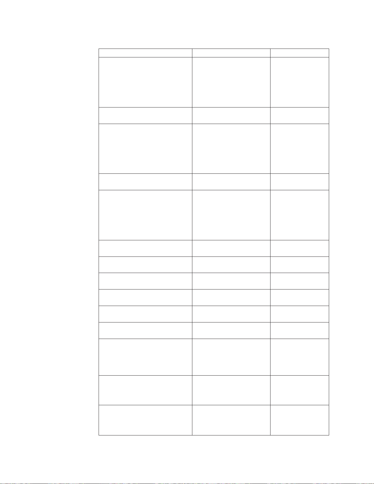
Table 7. Parallel and Serial Configuration (continued)
Parameters Values Default
Printer Compatibility 5
(Form Feed Suppression)
(When emulation mode is set to
4247, 4202 III XL,
or 2381)
Printer Compatibility 6
(Init)
Printer Compatibility 7
(Condensed Print)
(When emulation mode is set to
4247, 4202 III XL,
or 2381)
Printer Compatibility 8
(Slashed Zero)
Printer Compatibility 9
(20 CPI)
Disabled
Enabled
Enabled
Disabled
15
16.7
17.1
Disabled
Enabled
Enabled
Disabled
Disabled
Enabled
17.1
Disabled
Enabled
(When emulation mode is set to
4247, 4202 III XL,
or 2381)
Alarm Control Enabled
Disabled
Override Host
Paper Source
Override Host
Characters Per Inch
Override Host
Lines Per Inch
Override Host
Maximum Page Length
Parallel Interface
Interface Type
Parallel Interface
Input Buffer Size
Parallel Interface
Select-In Signal
(When emulation mode is set
to Epson-FX)
Parallel Interface
AutoFeed XT
(When emulation mode is set
to Epson-FX)
Enabled
Disabled
Enabled
Disabled
Enabled
Disabled
Enabled
Disabled
PC Parallel
1284 Parallel
256
2K
12K
32K
64K
Enabled
Disabled
Disabled
Enabled
Enabled
Disabled
Disabled
Disabled
Disabled
PC Parallel
32K
Enabled
Disabled
62 4247 Model 003 User’s Guide
Page 73

Table 7. Parallel and Serial Configuration (continued)
Parameters Values Default
Serial Interface
Interface Type
Serial Interface
Input Buffer Size
Serial Interface
Data Bits
Serial Interface
Baud Rate
Serial Interface
Parity
Serial Interface
Pacing Protocol
Serial Interface
Connection Type
RS-232C
RS-422A
256
2K
12K
32K
64K
7
8
300
600
1200
2400
4800
9600
19200
38400
None
Odd
Even
Mark
Space
DTR
XON/XOFF
Local
Remote
RS-232C
32K
8
9600
None
DTR
Local
Printer Setup
Table 8 lists the parameters available for the Printer Setup Category. Parameters
that can be overridden by the computer are noted with a dagger (†). Refer to
Chapter 10, “Printer Setup” for detailed information on setting these parameters.
Table 8. Printer Setup
Parameters Values Default
† Paper Source Front
ASF Default Bin
(when ASF installed)
ASF Bin 1 Media
(when ASF installed)
ASF Bin Linking
(when ASF installed)
Rear
Bin 1
Bin 2
Bin 3
Manual
Bin 1
Bin 2
Bin 3
Paper
Envelope
Disabled
Bin 1+2
Bin 1+2+3
Bin 2+3
Front
Bin 1
Paper
Disabled
Chapter 3. Checking and Changing Configuration Parameter Values 63
Page 74

Table 8. Printer Setup (continued)
Parameters Values Default
Front Forms Backup
(when front tractor installed)
Rear Forms Backup
(when rear tractor installed)
Continuous Forms Linking
(when front and rear tractors installed)
Form Feed Mode Not Active in Ready State
Automatic Eject Disabled
Automatic Restore Disabled
Continuous Forms Eject Mode Immediate Eject
Manual Paper Overlay Disabled
Automatic Manual Load Enabled
Manual Feed Eject Mode Top of Form
Bar Code Print Direction Unidirectional
Graphics Print Direction Unidirectional
Perforation Safety Disabled
Jam Sensors Enabled
Enabled
Disabled
Enabled
Disabled
Disabled
Enabled
Active in Ready State
Enabled
Data
Timer (10 seconds)
Timer (20 seconds)
Timer (30 seconds)
Timer (40 seconds)
Timer (50 seconds)
Delayed Eject
Enabled
Disabled
Automatic Top of Form
Bidirectional
Bidirectional
Enabled
Disabled
Enabled
Enabled
Disabled
Not Active in
Ready State
Disabled
Disabled
Immediate Eject
Disabled
Enabled
Top of Form
Unidirectional
Unidirectional
Disabled
Enabled
Printer Adjustment
Table 9 lists the parameters available for the Printer Adjustment Category. Refer to
Chapter 11, “Printer Adjustments” for detailed information on setting these
parameters.
Table 9. Printer Adjustment
Parameters Values Default
Front AFTA
(when front tractor installed)
Front Tear Position
(when front tractor installed)
Front Left Margin Alignment
(when front tractor installed)
64 4247 Model 003 User’s Guide
−5 to +3
Fixed 1 to 8
−312 to +24 0
0to60 10
0
Page 75

Table 9. Printer Adjustment (continued)
Parameters Values Default
Front Paper Load Position
(when front tractor installed)
Rear AFTA
(when rear tractor installed)
Rear Tear Position
(when rear tractor installed)
Rear Left Margin Alignment
(when rear tractor installed)
Rear Paper Load Position
(when rear tractor installed)
ASF Bin 1 AFTA
(when ASF installed)
ASF Bin 1 Left Margin Alignment
(when ASF installed)
ASF Bin 1 Paper Load Position
(when ASF installed)
ASF Bin 2 AFTA
(when ASF installed)
ASF Bin 2 Left Margin Alignment
(when ASF installed)
ASF Bin 2 Paper Load Position
(when ASF installed)
ASF Bin 3 AFTA
(when ASF installed)
ASF Bin 3 Left Margin Alignment
(when ASF installed)
ASF Bin 3 Paper Load Position
(when ASF installed)
Manual Feed AFTA −5 to +3
Manual Feed Left Margin Alignment 0 to 60 10
Manual Feed Paper Load Position −24 to +576 0
−24 to +288 0
−5 to +3
Fixed 1 to 8
−312 to +24 0
0to60 10
−24 to +288 0
−5 to +3
Fixed 1 to 8
0to60 10
−24 to +576 0
−5 to +3
Fixed 1 to 8
0to60 10
−24 to +576 0
−5 to +3
Fixed 1 to 8
0to60 10
−24 to +576 0
Fixed 1 to 8
0
0
0
0
0
Power On Reset
Table 10 lists the parameters available for the Power On Reset. Refer to Chapter 12,
“Power-On Reset (POR)” for detailed information on setting these parameters.
Table 10. Power On Reset
Parameters Values Default
Power On Reset Yes N/A
Display Language
Table 11 on page 66 lists the parameters available for the Display Language
Category. Refer to Chapter 13, “Display Language” for detailed information on
setting these parameters.
Chapter 3. Checking and Changing Configuration Parameter Values 65
Page 76

Table 11. Display Language
Parameters Values Default
Display Language 000 English
001 Deutsch
002 Français
003 Italiano
004 Español
005 Nederlands
006 Dansk
007 Português
008 Norsk
009 Svenska
010 Suomi
Send Buffer Reprint Code (Coax Attachment)
Table 12 lists the parameters available for the Send Buffer Reprint Code Category.
Refer to Chapter 14, “Send Buffer Reprint Code (Coax)” for detailed information on
setting these parameters.
Table 12. Send Buffer Reprint Code Category (Coax)
Parameters Values Default
Send Buffer Reprint Code Yes
No
000 English
No
Vital Product Data
Table 13 lists the parameters available for the Vital Product Data Category. Refer to
Chapter 15, “Vital Product Data” for detailed information on setting these
parameters.
Table 13. Vital Product Data Category
Parameters Values Default
Serial Number
Device Specific Information
Quit From Menu
Table 14 lists the parameters available for the Quit From Menu Category. Refer to
Chapter 16, “Quit From Menu” for detailed information on setting these
parameters.
Table 14. Quit From Menu Category
Parameters Values Default
Quit From Menu Restore Previous Values N/A
xxxxxxx
xxxxxxxxxxxxxxxx
0000000
0000000000000000
66 4247 Model 003 User’s Guide
Page 77

Chapter 4. Configuration Storage
Custom Sets ..............67
Non-Custom Set .............67
Save Current Values In Custom Sets ......68
Recall Custom Set Values ..........69
This chapter describes the procedures for setting configuration storage values. It
explains the two types of configuration storage (custom and non-custom) and
describes how to create and save them in printer memory.
Custom Sets
There are eight custom sets (A, B, C, D, E, F, G, and H) that you can create and
retain. Custom sets contain values for the following parameters:
v Twinax Configuration
– All, except Printer Address
v Coax Configuration
– All, except Screen Buffer Size and Programmed Symbols
v Parallel Configuration
– All, except Printer Compatibility 6 (Init), Interface Type, Input Buffer Size,
Select-In Signal, and AutoFeed XT
v Serial Configuration
– All, except Interface Type, Input Buffer Size, Data Bits, Baud Rate, Parity,
Pacing Protocol, and Connection Type
v Printer Setup
– All, except Paper Source
v Display Language
v Printer Adjustments
– All, except Bidirectional Adjustment, Sensor Tune, and Quit from Menu.
Power-On Custom Set ...........70
Power-On Paper Source ..........70
Recall Factory Defaults ..........71
Printing Custom Sets ...........72
Non-Custom Set
The non-custom set contains parameter values that stay the same, no matter which
custom set you are using. The following parameter values are saved in this part of
printer memory:
v Configuration Storage
– All
v Attachment
v Rear Tractor Use
v Twinax Configuration
– Printer Address
v Coax Configuration
– Screen Buffer Size
– Programmed Symbols
v Parallel Configuration
– Printer Compatibility 6 (Init)
– Interface Type
– Input Buffer Size
© Copyright IBM Corp. 2002 67
Page 78

– Select-In Signal
– AutoFeed-XT
v Serial Configuration
– All, except Interface Type, Input Buffer Size, Data Bits, Baud Rate, Parity,
Pacing Protocol, and Connection Type
v Printer Setup
– Paper Source
v Printer Adjustments
– Bidirectional Adjustment
– Sensor Tune
– Quit from Menu
v Power On Reset
–Yes
v Send Buffer Reprint (Coax)
–Yes
v Vital Product Data
v Quit From Menu
Changes to these values are saved at the same time you save values that go into
custom sets. If you save a change made to one of these non-custom set parameter
values, the new value will be in effect no matter which custom set you recall.
Save Current Values In Custom Sets
The Save Current Values stores the current values of the configuration parameters
to one of the eight custom sets (described in “Custom Sets” on page 67).
You can save the current values to:
v Custom Set A
v Custom Set B
v Custom Set C
v Custom Set D
v Custom Set E
v Custom Set F
v Custom Set G
v Custom Set H
All of the custom sets are initially set to the manufacturing default values.
To save current configuration values in a custom set, follow these steps:
1. Press Menu.
2. Press Scroll↑ or Scroll↓ until the printer displays
CONFIGURATION MENU
Configuration Storage
3. Press Enter.
4. Press Scroll↑ or Scroll↓ until the printer displays
Configuration Storage
Save Current Values
5. Press Enter to display the current value.
68 4247 Model 003 User’s Guide
Page 79

6. Press Scroll↑ or Scroll↓ until the desired custom set value is displayed.
Note: If you have previously created a custom set definition for that letter, that
information will be replaced with the new information when you press
Enter.
7. Press Enter.
The printer displays a message similar to
Save Current Values
Custom Set A Saved
8. Use Start or Return to exit the Menu. See “Exiting the Configuration Menu” on
page 55. The display will be updated to show the new custom set that is in use.
See “Custom Set In-Use Indicator” on page 40.
Recall Custom Set Values
The Recall Custom Set values recalls configuration parameters previously stored.
(Custom sets are described in “Custom Sets” on page 67.)
You can recall current values from:
v Custom Set A
v Custom Set B
v Custom Set C
v Custom Set D
v Custom Set E
v Custom Set F
v Custom Set G
v Custom Set H
Note: When a new custom set is recalled, a partial reset is automatically
performed when exiting from the configuration menu if the value of at least
one of the parameters that requires a partial reset has been changed.
Buffered data will be lost.
To recall custom set values, follow these steps:
1. Press Menu.
2. Press Scroll↑ or Scroll↓ until the printer displays
CONFIGURATION MENU
Configuration Storage
3. Press Enter.
4. Press Scroll↑ or Scroll↓ until the printer displays
Configuration Storage
Recall Custom Set Values
5. Press Enter to display the current value.
6. Press Scroll↑ or Scroll↓ until the desired custom set value is displayed.
7. Press Enter. The printer displays a message similar to
Recall Custom Set
Custom Set A Recalled
Chapter 4. Configuration Storage 69
Page 80

8. Use Start or Return to exit the Menu. See “Exiting the Configuration Menu” on
page 55.
Power-On Custom Set
The Power-On Custom Set is the custom set that is used when the printer is turned
on. The Last Used value means the custom set used before the printer was
powered off is to be used as the power-on custom set.
You can change the Power-On Custom Set to:
v Last Used (Default)
v Custom Set A
v Custom Set B
v Custom Set C
v Custom Set D
v Custom Set E
v Custom Set F
v Custom Set G
v Custom Set H
To change or check the power-on custom set, follow these steps:
1. Press Menu.
2. Press Scroll↑ or Scroll↓ until the printer displays
CONFIGURATION MENU
Configuration Storage
3. Press Enter.
4. Press Scroll↑ or Scroll↓ until the printer displays
Configuration Storage
Power-On Custom Set
5. Press Enter to display the current value.
6. Press Scroll↑ or Scroll↓ until the desired custom set for the new power-on
custom set is displayed.
7. Press Enter.
An asterisk (*) will be displayed in front of the selected custom set.
8. Use Start or Return to exit the Menu. See “Exiting the Configuration Menu” on
page 55.
Power-On Paper Source
The Power-On Paper Source allows you to select which paper source is to be used
when the printer is turned on. The Last Used value means that the paper source
used before the printer was powered off is to be used as the power-on paper
source.
You can change the Power-On Paper Source to:
v Front (Default)
v Rear
v Bin 1
v Bin 2
70 4247 Model 003 User’s Guide
Page 81

v Bin 3
v Manual
v Last Used
Selecting Last Used causes the Paper Source parameter (in the Printer Setup menu)
to be updated whenever the data stream selects a paper source. If the data stream
attempts to select the operator panel setting for power-on paper source, the most
recently selected paper source will be used instead.
To change or check the power-on paper source, follow these steps:
1. Press Menu.
2. Press Scroll↑ or Scroll↓ until the printer displays
CONFIGURATION MENU
Configuration Storage
3. Press Enter.
4. Press Scroll↑ or Scroll↓ until the printer displays
Configuration Storage
Power-On Paper Source
5. Press Enter to display the current value.
6. Press Scroll↑ or Scroll↓ until the desired Power-on Paper Source value is
displayed.
7. Press Enter.
An asterisk (*) will be displayed in front of the selected paper source.
8. Use Start or Return to exit the Menu. See “Exiting the Configuration Menu” on
page 55.
Recall Factory Defaults
This function sets all parameter values to the original manufacturing default
values, except Vital Product Data and Printer Address (twinax attachment). These
settings can only be changed through their own menu selection.
The printer is shipped with all of the custom sets set to manufacturing default
values and custom set A as the power-on custom set. The Recall Factory Defaults
function does not affect the values saved in custom sets.
Note: When factory defaults are recalled, a partial reset is automatically performed
when exiting from the configuration menu if the value of at least one of the
parameters that requires a partial reset has been changed. Buffered data will
be lost.
To recall the factory defaults, follow these steps:
1. Press Menu.
2. Press Scroll↑ or Scroll↓ until the printer displays
CONFIGURATION MENU
Configuration Storage
3. Press Enter.
Chapter 4. Configuration Storage 71
Page 82

4. Press Scroll↑ or Scroll↓ until the printer displays
Configuration Storage
Recall Factory Defaults
5. Press Enter.
The printer displays
Recall Factory Defaults
Yes
6. Press Enter.
The printer displays
Recall Factory Defaults
Factory Defaults Recalled
7. Use Start or Return to exit the Menu. See “Exiting the Configuration Menu” on
page 55.
Printing Custom Sets
Use this function to create a printout of the eight custom set values.
On the first page of the printout, each custom set is identified as either In Use or
as Factory Defaults.
In Use
At least one value in the custom set is different from the factory default
value. A flag (****) is printed after each parameter value that is different
from the factory default.
Factory Defaults
A custom set that is identical to one of the factory defaults.
If a custom set is identical to the factory defaults, it will be identified as Factory
Defaults. If the only change from factory defaults is a non-custom set parameter
value (a value that stays the same no matter which custom set you are using, such
as Twinax Address), only the first custom set will be identified as In Use. The
other custom sets will be shown as factory defaults.
To print the custom sets:
1. Press Stop to make the printer not ready.
2. Press Test.
3. Press Scroll↑ or Scroll↓ until the printer displays
4247 OPERATOR PRINT TESTS
Print Custom Sets
4. Use Enter or Start to begin the test. The printout will list all the custom sets.
The Ready indicator is lighted, and the Print Test prints. The printout is
complete when the Ready indicator is no longer lighted.
5. Press Cancel Print to make the printer ready,orReturn to make the printer not
ready.
72 4247 Model 003 User’s Guide
Page 83

Chapter 5. Changing Attachment Selection
This chapter describes the procedures for setting your printer attachment. Your
printer is capable of attaching individually through a twinax, coax, parallel, LAN,
or serial connection, or with a combination of parallel with a twinax, coax, or serial
connection. The attachments you have depend on what you requested at the time
you placed your order for the printer. To change or check the attachment selection,
follow these steps:
1. Press Menu.
2. Press Scroll↑ or Scroll↓ until the printer displays
CONFIGURATION MENU
Attachment
3. Press Enter.
The printer displays
Attachment
* xxxxxx
Where xxxxxx (depending on your currently selected attachment) can be
parallel, twinax, coax, or serial.
4. Press Scroll↑ or Scroll↓ until the desired value is displayed.
5. Press Enter.
An asterisk (*) will be displayed in front of the selected value.
6. Press Start or Return to exit the Menu. See “Exiting the Configuration Menu”
on page 55.
© Copyright IBM Corp. 2002 73
Page 84

74 4247 Model 003 User’s Guide
Page 85

Chapter 6. Rear Tractor Use
This chapter describes the Rear Tractor Use category in the Configuration Menu. It
is displayed in the operator panel display only when the rear tractor device is
installed and the ASF is not installed. If the ASF device is installed, the only
available value is Push. If Pull or Push-Pull needs to be used, the ASF device must
first be removed from the printer.
The following values for the Rear Tractor Use are:
Push (Default)
The rear tractor is used for the Rear Push paper path. This value is always
displayed.
Pull The rear tractor is used for the Rear Pull paper path. This value is only
displayed if the front tractor is not installed.
Push-Pull
The rear tractor is used for the Push-Pull paper path. Both rear and front
tractors must be installed for this value to be displayed.
To set the Rear Tractor Use value:
1. Press Menu.
2. Press Scroll↑ or Scroll↓ until the printer displays
CONFIGURATION MENU
Rear Tractor Use
3. Press Enter to display the current value.
4. Press Scroll↑ or Scroll↓ until the desired value is displayed.
5. Press Enter.
An asterisk (*) will be displayed in front of the selected value.
6. Press Start or Return to exit the Menu. See “Exiting the Configuration Menu”
on page 55.
© Copyright IBM Corp. 2002 75
Page 86

76 4247 Model 003 User’s Guide
Page 87

Chapter 7. Twinaxial Configuration
Characters Per Inch (CPI)..........77
Lines Per Inch (LPI) ...........78
Maximum Print Position (MPP)........78
Maximum Page Length (MPL) ........79
Print Quality ..............80
Print Language .............81
Printer Address .............82
This chapter describes how to check and change twinax configuration parameters
for your 4247 printer. The chapter is divided into sections according to parameter.
Refer to this partial table of contents for parameter and page listings.
Characters Per Inch (CPI)
You can set the Characters Per Inch (CPI) to any of the following values:
v 10 (Default)
v 12
v 15
v 16.7
Notes:
1. It is possible to specify a CPI value that causes the page width (maximum print
position) to exceed the maximum physical page width. If this occurs, the
printer automatically changes the maximum print position to the highest valid
value for the new CPI setting. See “Maximum Print Position (MPP)” on page 78
for more information.
2. This parameter can be overridden by the computer.
3. Only 10 CPI is valid when either OCR-A or OCR-B is selected as a print
language.
DataStream..............83
Emulation Mode.............84
Media Size Priority ............85
BarCodeMode.............85
Graphics Mode .............86
Alarm Control .............87
Override Host / Paper Source ........87
To change or check the CPI value, follow these steps:
1. Press Menu.
2. Press Scroll↑ or Scroll↓ until the printer displays
CONFIGURATION MENU
Twinax Configuration
3. Press Enter.
The printer displays
Twinax Configuration
Characters Per Inch
4. Press Enter to display the current value.
5. Press Scroll↑ or Scroll↓ until the desired value for CPI is displayed.
6. Press Enter.
An asterisk (*) will be displayed in front of the selected value.
7. Press Start or Return to exit the Menu. See “Exiting the Configuration Menu”
on page 55.
© Copyright IBM Corp. 2002 77
Page 88

Lines Per Inch (LPI)
You can set the lines per inch (LPI) for the printer to either of the following values:
v 6 (Default)
v 8
Note: This parameter can be overridden by the computer.
To change or check the LPI, follow these steps:
1. Press Menu.
2. Press Scroll↑ or Scroll↓ until the printer displays
CONFIGURATION MENU
Twinax Configuration
3. Press Enter.
4. Press Scroll↑ or Scroll↓ until the printer displays
Twinax Configuration
Lines Per Inch
5. Press Enter to display the current value.
6. Press Scroll↑ or Scroll↓ until the desired value for LPI is displayed.
7. Press Enter.
An asterisk (*) will be displayed in front of the selected value.
8. Press Start or Return to exit the Menu. See “Exiting the Configuration Menu”
on page 55.
Maximum Print Position (MPP)
The maximum print position (MPP) equals the number of characters the printer
prints on a line. The default value is 132.
The CPI setting you choose directly influences the MPP value you select. The MPP
and CPI settings determine the length of the print line. The maximum line length
for the printer is 345.44 mm (13.6 in.).
The CPI setting and the line length determine the MPP. Multiply the CPI by the
line length to determine the appropriate MPP:
MPP = CPI x line length (in inches)
If your CPI is: MPP cannot be greater than:
10 136
12 163
15 204
16.7 227
Notes:
1. Setting the MPP larger than the paper width can result in lost data because of
printing on the platen and may damage the platen and the printhead.
2. This parameter can be overridden by the computer.
78 4247 Model 003 User’s Guide
Page 89

To change or check the MPP value, follow these steps:
1. Press Menu.
2. Press Scroll↑ or Scroll↓ until the printer displays
CONFIGURATION MENU
Twinax Configuration
3. Press Enter.
4. Press Scroll↑ or Scroll↓ until the printer displays
Twinax Configuration
Maximum Print Position
5. Press Enter to display the current value.
6. Press Scroll↑ or Scroll↓ until the desired value for MPP is displayed.
7. Press Enter.
An asterisk (*) will be displayed in front of the selected value.
8. Press Start or Return to exit the Menu. See “Exiting the Configuration Menu”
on page 55.
Maximum Page Length (MPL)
You can set the maximum page length (MPL) for the printer from 1–660 lines for 6
LPI and 1–880 lines for 8 LPI. The default value is 66 lines.
MPL equals the number of print lines the printer can print on a page. MPL is the
page length stated in number of print lines.
See the following example to determine how to calculate the MPL.
The LPI and the page length determine the MPL. Multiply the lines per inch by the
page length to determine the appropriate MPL:
MPL = LPI x page length (in inches)
For example, if LPI=6 and page length=254 mm (10 in.), then
MPL=6x10
MPL = 60
254 mm
(10 in.)
Chapter 7. Twinaxial Configuration 79
Page 90

Note: This parameter can be overridden by the computer.
To change or check the MPL, follow these steps:
1. Press Menu.
2. Press Scroll↑ or Scroll↓ until the printer displays
CONFIGURATION MENU
Twinax Configuration
3. Press Enter.
4. Press Scroll↑ or Scroll↓ until the printer displays
Twinax Configuration
Maximum Page Length
5. Press Enter to display the current value.
6. Press Scroll↑ or Scroll↓ until the desired value for MPL is displayed.
7. Press Enter.
An asterisk (*) will be displayed in front of the selected value.
8. Press Start or Return to exit the Menu. See “Exiting the Configuration Menu”
on page 55.
Print Quality
You can set the Print Quality for the printer to any of the following values:
v DP (Data Processing) Quality (Default)
v DP Text Quality
v Near Letter Quality (NLQ).
Notes:
1. This parameter can be overridden by the computer.
2. Only Near Letter Quality is valid when either OCR-A or OCR-B is selected as
the print language.
To change or check the Print Quality, follow these steps:
1. Press Menu.
2. Press Scroll↑ or Scroll↓ until the printer displays
CONFIGURATION MENU
Twinax Configuration
3. Press Enter.
4. Press Scroll↑ or Scroll↓ until the printer displays
Twinax Configuration
Print Quality
5. Press Enter to display the current value.
6. Press Scroll↑ or Scroll↓ until the desired value for Print Quality is displayed.
7. Press Enter.
An asterisk (*) will be displayed in front of the selected value.
80 4247 Model 003 User’s Guide
Page 91

Print Language
8. Press Start or Return to exit the Menu. See “Exiting the Configuration Menu”
on page 55.
The following print languages are available on the printer when attachment is set
to Twinax. The default is marked with an asterisk (*). You can select any print
language that is available for your printer.
Determine the value for the language setting you want from the following table:
Code Page Language
37 USA/Canada
260 Canadian French
273 Austrian/German
274 Belgian Old
275 Brazilian
277 Danish/Norwegian
278 Finnish/Swedish
280 Italian
281 Japanese English
282 Portuguese
284 Spanish/Spanish Speaking
285 English (UK)
290 Japanese Katakana
297 French
420 Arabic
423 Greek (Old)
424 Hebrew
500 (*) International 5/Belgian New
833 Korean
838 Thai
870 Latin 2/ROECE
871 Icelandic
875 Greek (New)
880 Cyrillic
890 Yugoslav (Old)
892 OCR-A
893 OCR-B
924 Latin 9
1140 euro USA/Canada
1141 euro Austrian/German
1142 euro Danish/Norwegian
1143 euro Finnish/Swedish
1144 euro Italian
Chapter 7. Twinaxial Configuration 81
Page 92

Code Page Language
1145 euro Spanish/Spanish Speaking
1146 euro English (UK)
1147 euro French
1148 euro International 5/Belgian New
1149 euro Icelandic
1025 Cyrillic Multilingual
1026 Turkish
1097 Farsi
1112 Baltic Multilingual
1122 Estonian
Notes:
1. The printer performs a partial reset to put any change to this parameter value
into effect when you exit the Configuration Menu with Start or Return.
Buffered data will be lost.
2. This parameter can be overridden by the computer.
3. When either OCR-A or OCR-B is selected, the selectable options for CPI and
print quality become fixed at 10 CPI and Near Letter Quality, respectively.
Printer Address
To change or check the print language value, follow these steps:
1. Press Menu.
2. Press Scroll↑ or Scroll↓ until the printer displays
CONFIGURATION MENU
Twinax Configuration
3. Press Enter.
4. Press Scroll↑ or Scroll↓ until the printer displays
Twinax Configuration
Print Language
5. Press Enter to display the current value.
6. Press Scroll↑ or Scroll↓ until the desired language value is displayed.
7. Press Enter.
An asterisk (*) will be displayed in front of the selected value.
8. Press Start or Return to exit the Menu. See “Exiting the Configuration Menu”
on page 55.
The printer address is used by the host computer to communicate with the printer.
See your computer operator for the correct address for your printer.
Notes:
1. The printer performs a partial reset to put any change to this parameter value
into effect when you exit the Configuration Menu with Start or Return.
Buffered data will be lost.
82 4247 Model 003 User’s Guide
Page 93

2. When changing the value of the Printer Address, verify the Data Stream and
the Emulation Mode you have set.
You can set the Printer Address to any of the following values.
v 000 (Default)
v 001
v 002
v 003
v 004
v 005
v 006
To change or check the printer address setting, follow these steps:
1. Press Menu.
2. Press Scroll↑ or Scroll↓ until the printer displays
CONFIGURATION MENU
Twinax Configuration
3. Press Enter.
4. Press Scroll↑ or Scroll↓ until the printer displays
Twinax Configuration
Printer Address
Data Stream
5. Press Enter to display the current value.
6. Press Scroll↑ or Scroll↓ until the desired value for printer address is displayed.
7. Press Enter.
An asterisk (*) will be displayed in front of the selected value.
8. Press Start or Return to exit the Menu. See “Exiting the Configuration Menu”
on page 55.
This parameter is available only if the IPDS™feature is installed.
You can set the Data Stream to the following values:
v IPDS (Default)
v SCS
Notes:
1. The printer performs a partial reset to put any change to this parameter value
into effect when you exit the Configuration Menu with Start or Return.
Buffered data will be lost.
2. When changing the value of the Data Stream, verify the Emulation Mode and
the Printer Address you have set.
To change or check the data stream, follow these steps:
1. Press Menu.
2. Press Scroll↑ or Scroll↓ until the printer displays
CONFIGURATION MENU
Twinax Configuration
Chapter 7. Twinaxial Configuration 83
Page 94

Emulation Mode
3. Press Enter.
4. Press Scroll↑ or Scroll↓ until the printer displays
Twinax Configuration
Data Stream
5. Press Enter to display the current value.
6. Press Scroll↑ or Scroll↓ until the desired value for the data stream is displayed.
7. Press Enter.
An asterisk (*) will be displayed in front of the selected value.
8. Press Start or Return to exit the Menu. See “Exiting the Configuration Menu”
on page 55.
You can set Emulation Mode to the following values:
v 4247 (Default)
v 4224 (If IPDS feature is installed)
v 4230
v 4214 (If IPDS feature is not installed or the Data Stream parameter is set to SCS)
Notes:
1. The printer performs a partial reset to put any change to this parameter value
into effect when you exit the Configuration Menu with Start or Return.
Buffered data will be lost.
2. When changing the value of the Emulation Mode, verify the Data Stream and
the Printer Address you have set.
To change or check the emulation mode, follow these steps:
1. Press Menu.
2. Press Scroll↑ or Scroll↓ until the printer displays
CONFIGURATION MENU
Twinax Configuration
3. Press Enter.
4. Press Scroll↑ or Scroll↓ until the printer displays
Twinax Configuration
Emulation Mode
5. Press Enter to display the current value.
6. Press Scroll↑ or Scroll↓ until the desired value for Emulation Mode is
displayed.
7. Press Enter.
An asterisk (*) will be displayed in front of the selected value.
8. Press Start or Return to exit the Menu. See “Exiting the Configuration Menu”
on page 55.
84 4247 Model 003 User’s Guide
Page 95

Media Size Priority
This parameter is available only if the IPDS feature is installed, and the IPDS data
stream is selected. It affects the use of the XOH Set Media Size (SMS) order. This
order may be used in the IPDS data stream to set the page size. The Media Size
Priority setting specifies whether XOH-SMS orders take precedence over the
operator panel settings for maximum print position (MPP) and maximum page
length (MPL).
The following values will be displayed in the menu:
Standard
Alternate (default)
The media size is defined by the MPP and MPL parameters.
To change or check the Media Size Priority, follow these steps:
1. Press Menu.
2. Press Scroll↑ or Scroll↓ until the printer displays
The smaller page size values have priority. The page size will be the
intersection (smaller values) of the operator panel settings and the
XOH-SMS X and Y values.
The XOH-SMS order values have priority. If an XOH-SMS order is present,
its values will be used to define the page size instead of the operator panel
settings.
Bar Code Mode
CONFIGURATION MENU
Coax Configuration
3. Press Enter.
4. Press Scroll↑ or Scroll↓ until the printer displays
Coax Configuration
Media Size Priority
5. Press Enter to display the current value.
6. Press Scroll↑ or Scroll↓ until the desired value for media size priority is
displayed.
7. Press Enter.
An asterisk (*) will be displayed in front of the selected value.
8. Press Start or Return to exit the Menu. See “Exiting the Configuration Menu”
on page 55.
This parameter is valid only if the IPDS feature is installed and the IPDS data
stream is selected. Changing the value of this parameter can affect throughput in
some printing environments.
You can set the Bar Code Mode to any of the following values:
High (Default)
High Contrast Bar Codes
Low Low Contrast Bar Codes
Chapter 7. Twinaxial Configuration 85
Page 96

Computer Selected
Contrast as specified by the IPDS data stream
Note: The printer performs a partial reset to put any change to this parameter
value into effect when you exit the Configuration Menu with Start or
Return. Buffered data will be lost.
To change or check the bar code mode, follow these steps:
1. Press Menu.
2. Press Scroll↑ or Scroll↓ until the printer displays
CONFIGURATION MENU
Twinax Configuration
3. Press Enter.
4. Press Scroll↑ or Scroll↓ until the printer displays
Twinax Configuration
Bar Code Mode
5. Press Enter to display the current value.
6. Press Scroll↑ or Scroll↓ until the desired value for bar code mode is displayed
7. Press Enter.
An asterisk (*) will be displayed in front of the selected value.
8. Press Start or Return to exit the Menu. See “Exiting the Configuration Menu”
on page 55.
Graphics Mode
This parameter is available only if the IPDS feature is installed and the IPDS data
stream is selected. Changing the value of this parameter can affect throughput in
some printing environments.
You can set the Graphics Mode to any of the following values:
High (Default)
High Density Graphics
Low Low Density Graphics
Computer Selected
Density as specified by the IPDS data stream
Note: The printer performs a partial reset to put any change to this parameter
value into effect when you exit the Configuration Menu with Start or
Return. Buffered data will be lost.
To change or check the graphics mode, follow these steps:
1. Press Menu.
2. Press Scroll↑ or Scroll↓ until the printer displays
CONFIGURATION MENU
Twinax Configuration
3. Press Enter.
86 4247 Model 003 User’s Guide
Page 97

Alarm Control
4. Press Scroll↑ or Scroll↓ until the printer displays
Twinax Configuration
Graphics Mode
5. Press Enter to display the current value.
6. Press Scroll↑ or Scroll↓ until the desired value for graphics mode is displayed.
7. Press Enter.
An asterisk (*) will be displayed in front of the selected value.
8. Press Start or Return to exit the Menu. See “Exiting the Configuration Menu”
on page 55.
You can set the audible printer alarm to either of the following values:
v Enabled (Default)
v Disabled
Note: Pressing Set Top of Form and some unit check conditions sound the alarm,
even if it is disabled.
To change or check the alarm control, follow these steps:
1. Press Menu.
2. Press Scroll↑ or Scroll↓ until the printer displays
CONFIGURATION MENU
Twinax Configuration
3. Press Enter.
4. Press Scroll↑ or Scroll↓ until the printer displays
Twinax Configuration
Alarm Control
5. Press Enter to display the current value.
6. Press Scroll↑ or Scroll↓ until the desired value for alarm control is displayed.
7. Press Enter.
An asterisk (*) will be displayed in front of the selected value.
8. Press Start or Return to exit the Menu. See “Exiting the Configuration Menu”
on page 55.
Override Host / Paper Source
Override Host is a selection that determines whether the printer uses or overrides
(ignores) the SCS paper source selection commands sent by the host. IPDS paper
source selection commands sent from the host cannot be overridden.
Note: This selection appears in the Twinax Configuration menu only if the
parameter Data Stream is set to SCS.
You can set the Override Host / Paper Source selection to either of the following
values:
Chapter 7. Twinaxial Configuration 87
Page 98

Disabled (default)
Allows the host paper source selection commands to override the printer
operator panel paper source selection.
Enabled
Allows the operator panel selection for paper source to override host data
stream commands for paper source selection.
To change or check the Override Host / Paper Source selection, follow these steps:
1. Press Menu.
2. Press Scroll ↑ or Scroll ↓ until the printer displays
CONFIGURATION MENU
Twinax Configuration
3. Press Enter.
4. Press Scroll ↑ or Scroll ↓ until the printer displays
Twinax Configuration
Override Host
5. Press Enter and the printer displays
Override Host
Paper Source
6. Press Enter to display the current value.
7. Press Scroll ↑ or Scroll ↓ until the desired value for Override Host / Paper
Source is displayed.
8. Press Enter. An asterisk (*) will be displayed in front of the selected value.
9. Press Start or Return to exit the Menu.
88 4247 Model 003 User’s Guide
Page 99

Chapter 8. Coax Configuration
Characters Per Inch (CPI)..........89
Lines Per Inch (LPI) ...........90
Single/Double Space ...........90
Maximum Print Position (MPP)........91
Maximum Page Length (MPL) ........92
Emulation Mode.............93
Print Quality ..............94
Print Language .............94
Mono/Dual Case ............96
Print Text Direction............97
Media Size Priority ............97
Screen Buffer Size ............98
Printer Compatibility 1 (Carriage Return at MPP +
1)..................99
Printer Compatibility 2 (New Line at MPP + 1) . . 100
Printer Compatibility 3 (Form Feed Followed by
Data) ................101
Printer Compatibility 4 (Form Feed is Last
Character in Print Order) .........101
Printer Compatibility 5 (Null Suppression) . . . 102
Printer Compatibility 6 (Form Feed Command
Position) ...............103
This chapter describes the procedures for checking and changing coax
configuration parameters for your 4247 printer. The chapter is divided into sections
according to parameter. Refer to this partial table of contents for parameter and
page listings.
Printer Compatibility 7 (Automatic Function After
End of Print Buffer) ...........104
Printer Compatibility 8 (Automatic Function After
End of OILC Job) ............105
Printer Compatibility 9 (Suppress Timeout on No
Data Loss Intervention Required).......106
Early Print Complete ...........107
Printer Compatibility 12 (Automatic Function
Before Start of OILC Job) .........107
Form Feed Suppression ..........108
Programmed Symbols ..........109
Translate Table .............110
BarCodeMode.............110
Graphics Mode .............111
Alarm Control .............112
Override Host .............112
Using Programmed Symbols (PS) Parameters. . . 113
Plane Selection ............113
Full Page On Skip Suppress .......114
PS Print Direction ...........115
Characters Per Inch (CPI)
You can set the Characters Per Inch (CPI) to any of the following values:
v 10 (Default)
v 12
v 15
v 16.7
Notes:
1. It is possible to specify a CPI value that causes the page width (maximum print
position) to exceed the maximum physical page width. If this occurs, the
printer automatically changes the maximum print position to the highest valid
value for the new CPI setting. See “Maximum Print Position (MPP)” on page 91
for more information.
2. This parameter can be overridden by the computer.
3. Only 10 CPI is valid when either OCR-A or OCR-B is selected as a print
language.
To change or check the CPI value, follow these steps:
1. Press Menu.
2. Press Scroll↑ or Scroll↓ until the printer displays
CONFIGURATION MENU
Coax Configuration
© Copyright IBM Corp. 2002 89
Page 100

3. Press Enter.
The printer displays
Coax Configuration
Characters Per Inch
4. Press Enter to display the current value.
5. Press Scroll↑ or Scroll↓ until the desired value for CPI is displayed.
6. Press Enter.
An asterisk (*) will be displayed in front of the selected value.
7. Press Start or Return to exit the Menu. See “Exiting the Configuration Menu”
on page 55.
Lines Per Inch (LPI)
You can set the lines per inch (LPI) for the printer to either of the following values:
v 6 (Default)
v 8
Note: This parameter can be overridden by the computer.
To change or check the LPI, follow these steps:
1. Press Menu.
2. Press Scroll↑ or Scroll↓ until the printer displays
CONFIGURATION MENU
Coax Configuration
3. Press Enter.
4. Press Scroll↑ or Scroll↓ until the printer displays
Coax Configuration
Lines Per Inch
5. Press Enter to display the current value.
6. Press Scroll↑ or Scroll↓ until the desired value for LPI is displayed.
7. Press Enter.
An asterisk (*) will be displayed in front of the selected value.
8. Press Start or Return to exit the Menu. See “Exiting the Configuration Menu”
on page 55.
Single/Double Space
The single/double space parameter specifies the line spacing for line feed controls.
You can set the printer to print with either of the following line spacing:
v Single (Default)
v Double
Note: This parameter can be overridden by the computer.
To set the printer line spacing:
1. Press Menu.
90 4247 Model 003 User’s Guide
 Loading...