

Page 1

Gigabit Fibre Channel PCI Adapter
2-Gigabit Fibre Channel PCI Adapter
Installation and Using Guide
SA23-2550-02
Page 2

Third Edition (September 2001)
Before using this information and the product it supports, read the information in “Safety Information” on page v and
“Appendix B. Notices” on page 37.
A reader’s comment form is provided at the back of this publication. If the form has been removed, address comments
to Publications Department, Internal Zip 9561, 11400 Burnet Road, Austin, Texas 78758-3493. To send comments
electronically, use this commercial internet address: aix6kpub@austin.ibm.com. Any information that you supply may
be used without incurring any obligation to you.
© International Business Machines Corporation 2000, 2001. All rights reserved.
Note to U.S. Government Users Restricted Rights--Use, duplication or disclosure restricted by GSA ADP Schedule
Contract with IBM Corp.
Page 3

Contents
Safety Information.......................v
Laser Safety Information .....................v
Laser Compliance ......................v
Handling Static-Sensitive Devices.................vii
About This Book .......................ix
ISO 9000 ..........................ix
Related Publications ......................ix
Trademarks .........................ix
Chapter 1. Overview ......................1
Adapter Features .......................1
Gigabit Fibre Channel PCI Adapter (Type 4-S).............1
2-Gigabit Fibre Channel PCI Adapter (Type 4-W) ............2
Software Requirements .....................2
Environmental Requirements ...................2
Chapter 2. Preparing to Install a Gigabit Fibre Channel PCI Adapter .....3
Checking Prerequisites .....................3
Chapter 3. Installing Device Driver Software .............5
Installing the Software ......................5
Gigabit Fibre Channel PCI Adapter (Type 4-S).............5
2-Gigabit Fibre Channel PCI Adapter (Type 4-W) ............6
Chapter 4. Installing the Device Driver on the RS/6000 SP System......9
SP Device Driver Installation for Gigabit Fibre Channel PCI Adapter (Type 4-S). . . 9
Checking System Prerequisites ..................9
Installing Software on the Control Workstation ............12
Installing Device Drivers on the SP Nodes..............13
SP Device Driver Installation for 2-Gigabit Fibre Channel PCI Adapter (Type 4-W) 14
Checking System Prerequisites .................14
Installing Software on the Control Workstation ............17
Installing Device Drivers on the SP Nodes..............18
Chapter 5. Installing the Gigabit Fibre Channel PCI Adapter .......21
Installing the Adapter......................21
Verifying the Installation .....................21
Verifying Hardware Installation .................21
Verify AIX Software Installation .................22
Using SMIT to Configure Options for AIX 4.3.3 andAIX 5.1 .........23
Gigabit Fibre Channel Adapter Configuration .............23
Fibre Channel SCSI Protocol Driver Configuration ...........25
Chapter 6. Gigabit Fibre Channel PCI Adapter Interface .........27
iii
Page 4

Adapter LEDs ........................27
Product Descriptions ......................27
Product Summaries ......................27
Gigabit Fibre Channel PCI Adapter (Type 4-S) ............27
2-Gigabit Fibre Channel PCI Adapter (Type 4-W) ...........28
Cables ..........................28
Multimode 50 micron LC to LC Cables ...............28
Multimode 50 micron LC to SC Cables...............29
Appendix A. Communications Compliance Summary ..........31
Gigabit Fibre Channel PCI Adapter (Type 4-S) Communications Statements . . . 31
Federal Communications Commission (FCC) Statement .........31
European Union (EU) Statement .................32
International Electrotechnical Commission (IEC) Statement ........32
United Kingdom Telecommunications Safety Requirements ........32
Avis de conformité aux normes du ministère des Communications du Canada 32
Canadian Department of Communications Compliance Statement ......33
VCCI Statement ......................33
Radio Protection for Germany..................33
2-Gigabit Fibre Channel PCI Adapter (Type 4-W) Communications Statements . . 33
Federal Communications Commission (FCC) Statement .........33
European Union (EU) Statement .................34
International Electrotechnical Commission (IEC) Statement ........34
United Kingdom Telecommunications Safety Requirements ........34
Avis de conformité aux normes du ministère des Communications du Canada 35
Canadian Department of Communications Compliance Statement ......35
VCCI Statement ......................35
Electromagnetic Interference (EMI) Statement - Taiwan .........35
Radio Protection for Germany..................35
Appendix B. Notices .....................37
iv Installation and Using Guide
Page 5

Safety Information
DANGER
An electrical outlet that is not correctly wired could place hazardous voltage
on metal parts of the system or the devices that attach to the system. It is the
responsibility of the customer to ensure that the outlet is correctly wired and
grounded to prevent an electrical shock.
Before installing or removing signal cables, ensure that the power cables for
the system unit and all attached devices are unplugged.
When adding or removing any additional devices to or from the system,
ensure that the power cables for those devices are unplugged before the
signal cables are connected. If possible, disconnect all power cables from the
existing system before you add a device.
Use one hand, when possible, to connect or disconnect signal cables to
prevent a possible shock from touching two surfaces with different electrical
potentials.
During an electrical storm, do not connect cables for display stations, printers,
telephones, or station protectors for communication lines.
Laser Safety Information
Laser Compliance
All Lasers are certified in the U.S. to conform to the requirements of DHHS 21 CFR
Subchapter J for class 1 laser products. Outside the U.S., they are certified to be in
compliance with the IEC 825 (first edition 1984) as a class 1 laser product. Consult the
label on each part for laser certification numbers and approval information.
CAUTION:
All IBM laser modules are designed so that there is never any human access to
laser radiation above a class 1 level during normal operation, user maintenance,
or prescribed service conditions. Data processing environments can contain
equipment transmitting on system links with laser modules that operate at
greater than class 1 power levels. For this reason, never look into the end of an
optical fiber cable or open receptacle. Only trained service personnel should
perform the inspection or repair of optical fiber cable assemblies and receptacles.
v
Page 6

vi Installation and Using Guide
Page 7

Handling Static-Sensitive Devices
Attention: Static electricity can damage this device and your system unit. To avoid
damage, keep this device in its anti-static protective bag until you are ready to install it.
To reduce the possibility of electrostatic discharge, follow the precautions listed below:
v Limit your movement. Movement can cause static electricity to build up around you.
v Handle the device carefully, holding it by its edges or its frame.
v Do not touch solder joints, pins, or other printed circuitry.
v Do not leave the device where others can handle and possibly damage the device.
v While the device is still in its anti-static package, touch it to an unpainted metal part
of the system unit for at least two seconds. (This drains static electricity from the
package and from your body).
v Remove the device from its package and install it directly into your system unit
without setting it down. If it is necessary to set the device down, place it on its
static-protective package. (If your device is an adapter, place it component-side up).
Do not place the device on your system unit cover or on a metal table.
v Take additional care when handling devices during cold weather, as heating reduces
indoor humidity and increases static electricity.
vii
Page 8

viii Installation and Using Guide
Page 9

About This Book
This book provides information about installing the Gigabit Fibre Channel PCI Adapter
(Type 4-S) and the 2-Gigabit Fibre Channel PCI Adapter (Type 4-W). Use this book with
your specific system unit and operating system documentation.
ISO 9000
ISO 9000 registered quality systems were used in the development and manufacturing
of this product.
Related Publications
The following publications contain related information:
v System unit documentation for information specific to your hardware configuration
v Operating system documentation for information specific to your software
configuration
PCI Adapter Placement Reference
v
to contact your marketing representative)
v
Fibre Channel Storage Manager Installation and User’s Guide
latest version, you may need to contact your marketing representative)
Trademarks
The following terms are trademarks of International Business Machines Corporation in
the United States, other countries, or both:
v AIX
v RS/6000
v SP
, SA38-0538 (for the latest version, you may need
, SC26-7290 (for the
Other company, product, and service names may be trademarks or service marks of
others.
ix
Page 10

x Installation and Using Guide
Page 11
Chapter 1. Overview
Use a Gigabit Fibre Channel PCI Adapter (Type 4-S) to make high-speed connections
between stand-alone system units and storage servers on a fibre channel network at
speeds up to a Gigabit per second. This adapter requires a PCI 2.1, 32-bit, 33 MHz
slot.
Use a 2-Gigabit Fibre Channel PCI Adapter (Type 4-W) to make high-speed
connections between stand-alone system units and storage servers on a fibre channel
network at speeds up to two gigabits per second. This adapter requires a PCI 2.2,
64-bit, 66 MHz slot.
Adapter Features
Gigabit Fibre Channel PCI Adapter (Type 4-S)
v 1062Mb/s Fibre Channel Interface
v PCI Bus Compatible (32-bit slot)
v Supports Short Wave Optics (non-OFC)
v Upgradable microcode (See your System User’s Guide or contact your service
representative)
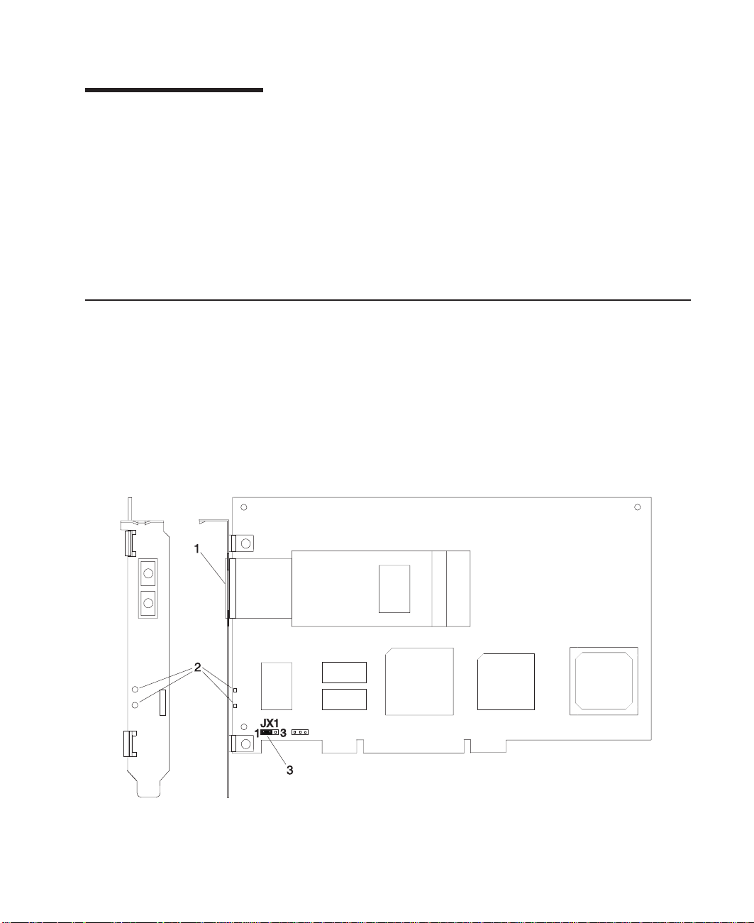
1. Multimode Fiber SC Connector
2. Data Link Status LEDs
3. Jumper JX1, Pins 1 to 2 only
1
Page 12

2-Gigabit Fibre Channel PCI Adapter (Type 4-W)
v 2-Gigabit per second Fibre Channel Interface
v PCI Bus Compatible (64-bit slot)
v Supports Short Wave Optics (non-OFC)
v Upgradable microcode (See your System User’s Guide or contact your service
representative)
1. Jumper JX1, Pins 1 to 2 only
2. Data Link Status LEDs
3. Multimode Fiber LC Connector
Software Requirements
The Gigabit Fibre Channel PCI Adapter (Type 4-S) and the 2-Gigabit Fibre Channel PCI
Adapter (Type 4-W) are supported on AIX Version 4.3.3 and later.
Environmental Requirements
v Operating temperature: 5 degrees C to 40 degrees C
v Operating humidity: 0 to 90% (non-condensing)
v Barometric operating pressure: 86 to 106 kPascals
v Maximum tolerance in power supply variation: +5% to -5%
2 Installation and Using Guide
Page 13

Chapter 2. Preparing to Install a Gigabit Fibre Channel PCI Adapter
This chapter helps you prepare to install a Gigabit Fibre Channel PCI Adapter.
Note: If AIX is not installed on your system unit, install your adapter before you install
the operating system. (See “Chapter 5. Installing the Gigabit Fibre Channel PCI
Adapter” on page 21) When you install AIX, your device driver software
automatically installs.
If AIX is operating on your system, install your device driver software before you
install your adapter. (See “Chapter 3. Installing Device Driver Software” on
page 5)
Checking Prerequisites
To install a Gigabit Fibre Channel PCI Adapter, you need the following on hand:
v The system unit documentation
v The operating system documentation
v A flat-blade screwdriver
v Media containing device driver software
3
Page 14

4 Installation and Using Guide
Page 15

Chapter 3. Installing Device Driver Software
The instructions in this chapter pertain to the AIX operating system. If you have another
operating system installed, refer to your operating system documentation for information
about installing the device software and configuring your system.
Installing the Software
This section contains instructions for installing the device driver software.
Gigabit Fibre Channel PCI Adapter (Type 4-S)
To install the device driver software, do the following:
1. Be sure you have read “Chapter 2. Preparing to Install a Gigabit Fibre Channel
PCI Adapter” on page 3 to determine:
v If you should install your device driver software first, go to step 2 and continue
with this section.
v If you should install your hardware first, go to chapter 5, ″Installing Hardware″.
When you install AIX, your adapter device driver automatically installs.
2. Turn on the system unit power.
3. At the system prompt, log in as root user.
4. Insert the media containing the device driver software (example: CD-ROM) into the
appropriate media device.
5. To start SMIT, type:
smitty devinst
Press Enter.
6. The Install Additional Device Software screen highlights the INPUT
device/directory for software option.
7. Select or type your input device:
v Press F4 to display the input device list. Select the name of the device
(example: CD-ROM) that you are using and press Enter.
OR
v In the Entry Field, type the name of the input device you are using and press
Enter.
8. The Install Additional Device Software panel highlights the SOFTWARE to install
option.
9. Press F4 to display a list of the device software you can install.
10. To display the Find window, type:
/
11. Type:
devices.pci.df1000f7
5
Page 16

Press Enter. The system finds and highlights this device driver software and
displays output similar to the following example:
4.3.3.0 devices.pci.df1000f7 ALL
12. Press PF7 to select the device software, and press Enter.
13. The Install Additional Device Software screen displays. Entry data fields are
automatically updated. Press Enter to accept the data.
14. The ARE YOU SURE window displays. Press Enter to accept the data.
15. The COMMAND STATUS window appears.
v The term RUNNING is highlighted to indicate that the install and configure
command is in progress.
v When RUNNING changes to OK, scroll down to the bottom of the page and locate
the Installation Summary.
v After a successful installation, SUCCESS displays in the Result column of the
summary at the bottom of the page.
16. Remove the installation media from the drive.
17. Press F10 to exit SMIT.
18. Go to the adapter installation procedure, “Chapter 5. Installing the Gigabit Fibre
Channel PCI Adapter” on page 21.
2-Gigabit Fibre Channel PCI Adapter (Type 4-W)
To install the device driver software, do the following:
1. Be sure you have read “Chapter 2. Preparing to Install a Gigabit Fibre Channel
PCI Adapter” on page 3 to determine:
v If you should install your device driver software first, go to step 2 and continue
with this section.
v If you should install your hardware first, go to chapter 5, ″Installing Hardware″.
When you install AIX, your adapter device driver automatically installs.
2. Turn on the system unit power.
3. At the system prompt, log in as root user.
4. Insert the media containing the device driver software (example: CD-ROM) into the
appropriate media device.
5. To start SMIT, type:
smitty devinst
Press Enter.
6. The Install Additional Device Software screen highlights the INPUT
device/directory for software option.
7. Select or type your input device:
v Press F4 to display the input device list. Select the name of the device
(example: CD-ROM) that you are using and press Enter.
OR
v In the Entry Field, type the name of the input device you are using and press
Enter.
6 Installation and Using Guide
Page 17

8. The Install Additional Device Software panel highlights the SOFTWARE to install
option.
9. Press F4 to display a list of the device software you can install.
10. To display the Find window, type:
/
11. Type:
devices.pci.df1000f9
Press Enter. The system finds and highlights this device driver software and
displays output similar to the following example:
4.3.3.0 devices.pci.df1000f9 ALL
12. Press PF7 to select the device software, and press Enter.
13. The Install Additional Device Software screen displays. Entry data fields are
automatically updated. Press Enter to accept the data.
14. The ARE YOU SURE window displays. Press Enter to accept the data.
15. The COMMAND STATUS window appears.
v The term RUNNING is highlighted to indicate that the install and configure
command is in progress.
v When RUNNING changes to OK, scroll down to the bottom of the page and locate
the Installation Summary.
v After a successful installation, SUCCESS displays in the Result column of the
summary at the bottom of the page.
16. Remove the installation media from the drive.
17. Press F10 to exit SMIT.
18. Go to the adapter installation procedure, “Chapter 5. Installing the Gigabit Fibre
Channel PCI Adapter” on page 21.
Chapter 3. Installing Device Driver Software 7
Page 18

8 Installation and Using Guide
Page 19

Chapter 4. Installing the Device Driver on the RS/6000 SP System
For an SP system, the installation tasks must be performed on each node. You must
make the installation files available and then install them on all the relevant nodes. This
chapter discusses the following tasks to enable you to install the device driver on the
RS/6000 SP System:
v Checking System Prerequisites
v Installing Software on the Control Workstation (
lppsource directory)
v Installing Device Drivers on the SP Nodes (
software are not already installed)
Perform the following tasks on the Control Workstation. If you are unfamiliar with the
dsh command, refer to one of the following Parallel System Support Program (PSSP)
publications:
v
Parallel System Support Program for AIX: Administration Guide
v
Parallel System Support Program for AIX: Command and Technical Reference
If you cannot use the dsh command because of the setup at your site, then use the
telnet command to each node. Then perform the steps below, beginning with step 5,
and omitting the dsh prefix.
For information about installing the device driver for the Gigabit Fibre Channel PCI
Adapter (Type 4-S), see “SP Device Driver Installation for Gigabit Fibre Channel PCI
Adapter (Type 4-S)”, below.
if
the device driver is not in the
if
the device driver and additional
For information about installing the device driver for the 2-Gigabit Fibre Channel PCI
Adapter (Type 4-W), see “SP Device Driver Installation for 2-Gigabit Fibre Channel PCI
Adapter (Type 4-W)” on page 14.
SP Device Driver Installation for Gigabit Fibre Channel PCI Adapter (Type 4-S)
Checking System Prerequisites
Do the following to check system prerequisites:
__ 1. Log into the Control Workstation as a root user.
__ 2. Go to a temporary directory by typing the following at the system prompt:
cd /tmp
Press Enter.
__ 3. Make a ″working collective″ file containing a list of the relevant nodes on which
you want to perform the update. Type the following, pressing Enter after each
line:
9
Page 20

cat > group1
nodename1
nodename2
nodename3......
CTRL-D
export WCOLL=/tmp/group1
__ 4. Test the working collective file by typing the following:
dsh date
Press Enter. The results should look similar to the following:
nodename1: Wed Apr 10 10:37:46 EDT 1999
nodename2: Wed Apr 10 10:37:46 EDT 1999
nodename3: Wed Apr 10 10:37:47 EDT 1999
nodename4: Wed Apr 10 10:37:48 EDT 1999
If not, examine your nodelist file /tmp/group1 to ensure that the node names
are correct. Also ensure that the Kerberos ticket is current to permit rsh to be
performed. If not, you may need to refresh it. Contact your system administrator
for assistance with Kerberos initialization. If the system administrator is unable
to help you, consult your support center.
An alternative way to specify a working collective is by using the -w flag with
the dsh command. If you need to install only a few nodes, use the dsh -w
host1, host2, host3...command format to explicitly reference groups of nodes.
__ 5. Determine if the AIX operating system on each relevant node is at the required
level by typing the following at the prompt:
dsh oslevel
OR
dsh -w <host1,host2> oslevel
Press Enter. <host1,host2> is a list of the host names for the nodes on which
the adapter will be installed. The required AIX level is: 4.3.3 or later.
If the nodes are
nodes. Contact the system administrator for assistance.
__ 6. Determine if the PSSP level on each node is at the required level by typing the
following:
/usr/lpp/ssp/bin/splstdata -G -b
Press Enter. The results display for all nodes and are in a form similar to the
following:
node# hostname hdw_enet_addr srvr response install_disk
last_install_image last_install_time next_install_image lppsource_name
------------------------------------------------------------------------
10 Installation and Using Guide
not
at a supported AIX level, upgrade the AIX level on the
pssp_ver
Page 21

1 eion01.ppd.pok.i 08005A75A6D4 0 disk hdisk0
<lppsource> is the lppsource name for the node. <pssp level> is the PSSP
level installed on the node. The required PSSP level is 3.1.1 or later.
default Thu_Dec__4_09:07:23 default <lppsource>
<pssp level>
If the nodes are
nodes. Contact the system administrator for assistance.
__ 7. Record the name that appears below lppsource_name for each node on which
the adapters are being installed. You will use this information later.
__ 8. Verify that the device driver is installed in the lppsource directory by typing the
following at the system prompt:
cd spdata/sys1/install/<lppsource_name>/lppsource
<lppsource_name> was recorded in the previous step. Once you are in this
directory, verify that the fileset is in the lppsource directory by typing the
following at the prompt:
ls devices.pci.14100401*
If the device driver is not in the lppsource directory, proceed to section
“Installing Software on the Control Workstation” on page 12 to install the
software.
__ 9. Update the SPOT (Shared Product Object Tree) by doing the following:
__ a. Type the following at the system prompt:
smitty nim_res_op
The Resource Name screen displays with the following highlighted:
boot resources boot
__ b. Move the cursor down until the
resource
spot_AIX433 resources spot
not
at a supported PSSP level, upgrade the PSSP level on the
SPOT resource
should look similar to:
is highlighted. The
SPOT
The format of the spot name is: spot_<lppsource_name>.
<lppsource_name> was the name you recorded in a previous step.
__ c. When the
The Network Install Operation to Perform screen displays with the reset
option highlighted for selection.
__ d. Move the cursor until the cust option is highlighted and press Enter to
select this option. The Customize a SPOT screen displays with the
Source of Install Images highlighted for selection.
__ e. Press F4 to display the list of installation images and select the
appropriate lppsource.
__ f. Move the cursor until the appropriate lppsource is displayed. For
example:
SPOT resource
Chapter 4. Installing the Device Driver on the RS/6000 SP System 11
is highlighted, press Enter to select this option.
Page 22

lppsource_AIX433 resources lpp_source
Press Enter.
__ g. Move the cursor until
fileset name:
devices.pci.14100401*
__ h. Press Enter to start the SPOT update. This operation can take up to 15
minutes.
__ 10. Verify that the device driver is already installed by typing the following at the
system prompt:
dsh "lslpp -l devices.pci.14100401* 2>&1" |more
__ 11. If the device driver is already installed on the node, contact your service
provider to have the adapter installed.
OR
If the device driver is not installed on the node, proceed to section “Installing
Device Drivers on the SP Nodes” on page 13.
Fileset Names
Installing Software on the Control Workstation
is highlighted. Type the following
Note: If your system is
among the nodes, you may
or later.
__ 1. If you are not logged into the Control Workstation as a root user, log in now. You
may also need to export the working collective. Refer to “Checking System
Prerequisites” on page 9.
__ 2. Select the appropriate CD-ROM for the operating system, as follows:
v AIX 4.3.x - Additional Device Software
__ 3. Insert the installation media into the drive of the Control Workstation.
__ 4. Transfer the files to the Control Workstation’s lppsource, as follows:
a. Type the following, and then press Enter.
smitty bffcreate
b. Select the input device/directory. Press F4. Then move the cursor to the
appropriate input device and press Enter.
c. Move the cursor to the SOFTWARE package to copy option and press F4
to select the software to be installed. Use the F7 key to select the following
device driver(s) at the system prompt:
devices.pci.14100401
Press Enter.
d. Move the cursor down to DIRECTORY for storing software package and
enter the appropriate lppsource destination directory:
/spdata/sys1/install/<lppsource_name>/lppsource
partitioned
; that is, there are more than one operating system
only
install this adapter in nodes that haveAIX 4.3.3
Use the <lppsource_name> you recorded earlier.
12 Installation and Using Guide
Page 23

e. Press Enter to begin copying the files.
Note: This step may take several minutes while the directory table of
contents is updated.
__ 5. Update the SPOT (Shared Product Object Tree) by doing the following:
a. Type the following at the system prompt:
smitty nim_res_op
The Resource Name screen displays with the following highlighted:
boot resources boot
b. Move the cursor down until the
resource
spot_AIX433 resources spot
The format of the spot name is: spot_<lppsource_name>. <lppsource_name>
was the name that you recorded in a previous step.
c. When the
The Network Install Operation to Perform screen displays with the reset
option highlighted for selection.
d. Move the cursor until the cust option is highlighted, and press Enter to select
this option. The Customize a SPOT screen displays with the Source of
Install Images highlighted for selection.
e. Press F4 to display the list of installation images and select the appropriate
lppsource.
f. Move the cursor until the appropriate lppsource is displayed. For example:
lppsource_AIX433 resources lpp_source
should look similar to:
SPOT resource
SPOT resource
is highlighted, press Enter to select this option.
is highlighted. The
SPOT
Press Enter.
g. Move the cursor down until
fileset name:
devices.pci.14100401
h. Press Enter to start the SPOT update. This operation can take up to 15
minutes.
__ 6. Proceed to step 9 on page 11.
Installing Device Drivers on the SP Nodes
Do the following to install device drivers on the SP nodes:
__ 1. Make sure that the lppsource directory is exported to the nodes by typing the
following at the system prompt:
showmount -e
If the directory is exported to the nodes, the result should look similar to the
following:
/spdata/sys1/install/AIX433/lppsource (everyone)
Chapter 4. Installing the Device Driver on the RS/6000 SP System 13
fileset names
is highlighted. Type the following
Page 24

__ 2. If the directory is not exported, you may temporarily export the directory by
typing the following:
exportfs -i /spdata/sys1/install/<lppsource_name>/lppsource
__ 3. Perform an NFS mount of the lppsource directory by typing the following:
dsh mount <controlwks>:
/spdata/sys1/install/<lppsource_name>/lppsource /mnt
<controlwks> is the name of the Control Workstation recognized by the nodes.
<lppsource_name> is the name you recorded earlier in “Checking System
Prerequisites” on page 9.
__ 4. Perform a preview of the files to be installed on the nodes by typing the following
at the system prompt:
dsh "installp -p -acqXd /mnt device driver 2>&1" | more
device driver
v devices.pci.14100401
__ 5. Install the device driver by typing the following at the system prompt:
dsh "installp -acqXd /mnt device driver 2>&1" | more
device driver
After the device driver is installed on the node, contact your service provider to
have the adapter installed.
is the fileset that must be installed for the adapter. The list includes:
is defined in the previous step.
SP Device Driver Installation for 2-Gigabit Fibre Channel PCI Adapter (Type 4-W)
Checking System Prerequisites
Do the following to check system prerequisites:
__ 1. Log into the Control Workstation as a root user.
__ 2. Go to a temporary directory by typing the following at the system prompt:
cd /tmp
Press Enter.
__ 3. Make a ″working collective″ file containing a list of the relevant nodes on which
you want to perform the update. Type the following, pressing Enter after each
line:
cat > group1
nodename1
nodename2
nodename3......
CTRL-D
export WCOLL=/tmp/group1
__ 4. Test the working collective file by typing the following:
dsh date
14 Installation and Using Guide
Page 25

Press Enter. The results should look similar to the following:
nodename1: Wed Apr 10 10:37:46 EDT 1999
nodename2: Wed Apr 10 10:37:46 EDT 1999
nodename3: Wed Apr 10 10:37:47 EDT 1999
nodename4: Wed Apr 10 10:37:48 EDT 1999
If not, examine your nodelist file /tmp/group1 to ensure that the node names
are correct. Also ensure that the Kerberos ticket is current to permit rsh to be
performed. If not, you may need to refresh it. Contact your system administrator
for assistance with Kerberos initialization. If the system administrator is unable
to help you, consult your support center.
An alternative way to specify a working collective is by using the -w flag with
the dsh command. If you need to install only a few nodes, use the dsh -w
host1, host2, host3...command format to explicitly reference groups of nodes.
__ 5. Determine if the AIX operating system on each relevant node is at the required
level by typing the following at the prompt:
dsh oslevel
OR
dsh -w <host1,host2> oslevel
Press Enter. <host1,host2> is a list of the host names for the nodes on which
the adapter will be installed. The required AIX level is: 4.3.3 or later.
If the nodes are
not
at a supported AIX level, upgrade the AIX level on the
nodes. Contact the system administrator for assistance.
__ 6. Determine if the PSSP level on each node is at the required level by typing the
following:
/usr/lpp/ssp/bin/splstdata -G -b
Press Enter. The results display for all nodes and are in a form similar to the
following:
node# hostname hdw_enet_addr srvr response install_disk
last_install_image last_install_time next_install_image lppsource_name
pssp_ver
-----------------------------------------------------------------------1 eion01.ppd.pok.i 08005A75A6D4 0 disk hdisk0
default Thu_Dec__4_09:07:23 default <lppsource>
<pssp level>
<lppsource> is the lppsource name for the node. <pssp level> is the PSSP
level installed on the node. The required PSSP level is 3.1.1 or later.
If the nodes are
not
at a supported PSSP level, upgrade the PSSP level on the
nodes. Contact the system administrator for assistance.
Chapter 4. Installing the Device Driver on the RS/6000 SP System 15
Page 26

__ 7. Record the name that appears below lppsource_name for each node on which
the adapters are being installed. You will use this information later.
__ 8. Verify that the device driver is installed in the lppsource directory by typing the
following at the system prompt:
cd spdata/sys1/install/<lppsource_name>/lppsource
<lppsource_name> was recorded in the previous step. Once you are in this
directory, verify that the fileset is in the lppsource directory by typing the
following at the prompt:
ls devices.pci.df1000f9*
If the device driver is not in the lppsource directory, proceed to section
“Installing Software on the Control Workstation” on page 17 to install the
software.
__ 9. Update the SPOT (Shared Product Object Tree) by doing the following:
__ a. Type the following at the system prompt:
smitty nim_res_op
The Resource Name screen displays with the following highlighted:
boot resources boot
__ b. Move the cursor down until the
resource
spot_AIX433 resources spot
should look similar to:
SPOT resource
is highlighted. The
SPOT
__ c. When the
__ d. Move the cursor until the cust option is highlighted and press Enter to
__ e. Press F4 to display the list of installation images and select the
__ f. Move the cursor until the appropriate lppsource is displayed. For
__ g. Move the cursor until
__ h. Press Enter to start the SPOT update. This operation can take up to 15
16 Installation and Using Guide
The format of the spot name is: spot_<lppsource_name>.
<lppsource_name> was the name you recorded in a previous step.
SPOT resource
The Network Install Operation to Perform screen displays with the reset
option highlighted for selection.
select this option. The Customize a SPOT screen displays with the
Source of Install Images highlighted for selection.
appropriate lppsource.
example:
lppsource_AIX433 resources lpp_source
Press Enter.
fileset name:
devices.pci.df1000f9*
minutes.
is highlighted, press Enter to select this option.
Fileset Names
is highlighted. Type the following
Page 27

__ 10. Verify that the device driver is already installed by typing the following at the
system prompt:
dsh "lslpp -l devices.pci.df1000f9* 2>&1" |more
__ 11. If the device driver is already installed on the node, contact your service
provider to have the adapter installed.
OR
If the device driver is not installed on the node, proceed to section “Installing
Device Drivers on the SP Nodes” on page 18.
Installing Software on the Control Workstation
Note: If your system is
among the nodes, you may
or later.
__ 1. If you are not logged into the Control Workstation as a root user, log in now. You
may also need to export the working collective. Refer to “Checking System
Prerequisites” on page 9.
__ 2. Select the appropriate CD-ROM for the operating system, as follows:
v AIX 4.3.x - Additional Device Software
__ 3. Insert the installation media into the drive of the Control Workstation.
__ 4. Transfer the files to the Control Workstation’s lppsource, as follows:
a. Type the following, and then press Enter.
smitty bffcreate
b. Select the input device/directory. Press F4. Then move the cursor to the
appropriate input device and press Enter.
c. Move the cursor to the SOFTWARE package to copy option and press F4
to select the software to be installed. Use the F7 key to select the following
device driver(s) at the system prompt:
devices.pci.df1000f9
Press Enter.
d. Move the cursor down to DIRECTORY for storing software package and
enter the appropriate lppsource destination directory:
/spdata/sys1/install/<lppsource_name>/lppsource
partitioned
; that is, there are more than one operating system
only
install this adapter in nodes that haveAIX 4.3.3
Use the <lppsource_name> you recorded earlier.
e. Press Enter to begin copying the files.
Note: This step may take several minutes while the directory table of
contents is updated.
__ 5. Update the SPOT (Shared Product Object Tree) by doing the following:
a. Type the following at the system prompt:
smitty nim_res_op
Chapter 4. Installing the Device Driver on the RS/6000 SP System 17
Page 28

The Resource Name screen displays with the following highlighted:
boot resources boot
b. Move the cursor down until the
resource
spot_AIX433 resources spot
The format of the spot name is: spot_<lppsource_name>. <lppsource_name>
was the name that you recorded in a previous step.
c. When the
The Network Install Operation to Perform screen displays with the reset
option highlighted for selection.
d. Move the cursor until the cust option is highlighted, and press Enter to select
this option. The Customize a SPOT screen displays with the Source of
Install Images highlighted for selection.
e. Press F4 to display the list of installation images and select the appropriate
lppsource.
f. Move the cursor until the appropriate lppsource is displayed. For example:
lppsource_AIX433 resources lpp_source
Press Enter.
g. Move the cursor down until
fileset name:
devices.pci.df1000f9
h. Press Enter to start the SPOT update. This operation can take up to 15
minutes.
__ 6. Proceed to step 9 on page 16.
should look similar to:
SPOT resource
SPOT resource
is highlighted, press Enter to select this option.
fileset names
is highlighted. The
is highlighted. Type the following
SPOT
Installing Device Drivers on the SP Nodes
Do the following to install device drivers on the SP nodes:
__ 1. Make sure that the lppsource directory is exported to the nodes by typing the
following at the system prompt:
showmount -e
If the directory is exported to the nodes, the result should look similar to the
following:
/spdata/sys1/install/AIX433/lppsource (everyone)
__ 2. If the directory is not exported, you may temporarily export the directory by
typing the following:
exportfs -i /spdata/sys1/install/<lppsource_name>/lppsource
__ 3. Perform an NFS mount of the lppsource directory by typing the following:
dsh mount <controlwks>:
/spdata/sys1/install/<lppsource_name>/lppsource /mnt
18 Installation and Using Guide
Page 29

<controlwks> is the name of the Control Workstation recognized by the nodes.
<lppsource_name> is the name you recorded earlier in “Checking System
Prerequisites” on page 14.
__ 4. Perform a preview of the files to be installed on the nodes by typing the following
at the system prompt:
dsh "installp -p -acqXd /mnt device driver 2>&1" | more
device driver
is the fileset that must be installed for the adapter. The list includes:
v devices.pci.df1000f9
__ 5. Install the device driver by typing the following at the system prompt:
dsh "installp -acqXd /mnt device driver 2>&1" | more
device driver
is defined in the previous step.
After the device driver is installed on the node, contact your service provider to
have the adapter installed.
Chapter 4. Installing the Device Driver on the RS/6000 SP System 19
Page 30

20 Installation and Using Guide
Page 31

Chapter 5. Installing the Gigabit Fibre Channel PCI Adapter
This chapter provides instructions for installing the Gigabit Fibre Channel PCI Adapter.
Attention: Be sure you have read “Handling Static-Sensitive Devices” on page vii
before handling your Gigabit Fibre Channel PCIAdapter. Do not remove the Gigabit
Fibre Channel PCI Adapter from its anti-static package at this time.
Installing the Adapter
To install the adapter, do the following:
1. Be sure you have read “Chapter 2. Preparing to Install a Gigabit Fibre Channel PCI
Adapter” on page 3 to determine:
v If you should install your adapter hardware first
v If you should install your device driver software first
2. If you should install your adapter hardware first, go to step 4 and continue with this
section.
3. If you should install your device driver software first, go back to “Chapter 3.
Installing Device Driver Software” on page5. Return here to install your hardware.
4. Refer to the system unit documentation that shipped with your system unit to
perform the following:
a. Shut down your system unit.
b. Install the adapter into your system unit in any primary PCI bus.
5. After the installation is complete, connect the cable to the adapter.
6. Turn on your system unit. Go to “Verifying Hardware Installation”, below.
Verifying the Installation
Verify the initial installation by using the following procedures:
v Verify Hardware Installation (lsdev)
v Verify AIX Software Installation (lslpp)
Verifying Hardware Installation
To verify your system unit recognizes the Gigabit Fibre Channel PCI Adapter, do the
following:
1. If necessary, log in as root.
2. Type:
lsdev -C s grep fcs0
If more than one fibre channel device is installed, the value
3. Press Enter.
Possible results are as follows:
fcs0
may vary.
21
Page 32

v If the adapter did install, the following is an example of the data that displays on
your screen:
fcs0 Available 20-60
v If the message on your screen indicates your adapter is Defined instead of
Available, shut down your machine. Check the adapter to ensure that it is
installed correctly. Go to “Chapter 5. Installing the Gigabit Fibre Channel PCI
Adapter” on page 21, and return to “Verifying Hardware Installation” on page21
and repeat steps 1-3.
Note: If the message on your screen indicates your adapter is Defined a second
time, it may be necessary to contact your service representative.
v If no data displays on your screen, two possible problems exist:
– Device drivers did not install. Go to “VerifyAIX Software Installation”.
– Adapter did not install correctly. Go to “Chapter 5. Installing the Gigabit Fibre
Channel PCI Adapter” on page 21, and return to “Verifying Hardware
Installation” on page 21 and repeat steps 1-3.
If that is not the problem, check your adapter installation. Go to “Chapter 3.
Installing Device Driver Software” on page5.
Verify AIX Software Installation
To verify that the device driver for the adapter is installed, do the following:
1. If necessary, log in as root user.
2. Type:
lslpp -h s grep -p df1000f7
3. Press Enter.
Possible results are as follows:
v If the device driver is installed, the following is an example of the data that
displays on your screen:
devices.pci.df1000f7.rte 4.3.x.x COMMITTED IBM PCI Adapter
devices.pci.df1000f7.com 4.3.x.x COMMITTED IBM PCI Adapter
devices.fcp.disk.array.rte 4.3.x.x COMMITTED IBM PCI Adapter
devices.pci.df1000f7.diag 4.3.x.x COMMITTED IBM PCI
devices.fcp.disk.array.diag 4.3.x.x COMMITTED IBM PCI Adapter
Adapter (df1000f7) Diagnostics
If this displays on your screen but you continue to have problems, go to
“Chapter 5. Installing the Gigabit Fibre Channel PCI Adapter” on page 21.
v If no data displays on your screen, the adapter device driver did not install
correctly. Return to “Chapter 3. Installing Device Driver Software” on page 5.
22 Installation and Using Guide
Page 33

Using SMIT to Configure Options for AIX 4.3.3 and AIX 5.1
This section provides instructions for configuring options for the Gigabit Fibre Channel
adapter.
Use SMIT to configure options as follows:
1. Log in as root user.
2. To start SMIT, type:
smit
Press Enter.
3. Select Devices.
Gigabit Fibre Channel Adapter Configuration
To configure the Gigabit Fibre Channel (FC) Adapter, do the following:
1. Select the FC Adapter section.
FC Adapter Configurable Options are displayed on the screen.
2. Select Change/Show Characteristics.
A list of configurable FC Adapter options is displayed.
Change/Show Characteristics of a FC Adapter
Type or select values in entry fields.
Press Enter AFTER making all desired changes.
FC Adapter fcs0
Description FC Adapter
Status Available
Location 20-58
Maximum number of COMMANDS to queue to the adapter [200]+#
Maximum Transfer Size [0x100000]+
Preferred AL_PA [0x1]+
INIT Link flags [al]+
Apply change to DATABASE only no+
[Entry Fields]
Configuration Options
The FC Adapter has the following configuration options:
v Maximum Number of Commands to Queue to the Adapter
v Maximum Transfer Size
v Preferred AL_PA
v INIT Link Flags (AIX Version 5.1 only)
Maximum Number of Commands to Queue to the Adapter:
adapt to various memory/system conditions. The default is 200, but you can conserve
memory at the expense of performance by reducing this number to as little as 20. If you
Chapter 5. Installing the Gigabit Fibre Channel PCI Adapter 23
Use this option to
Page 34

have sufficient memory, the maximum is 1024 for a Gigabit Fibre Channel PCI Adapter
(Type 4-S). The maximum is 2048 for a 2-Gigabit Fibre Channel PCI Adapter (Type
4-W).
If the SCSI target device is connected to the host through a SAN Data Gateway (SDG),
then this parameter cannot exceed the SDG limit of 240 (SAN Data Gateway is a
SCSI-to-Fibre Channel bridge).
Maximum Transfer Size:
transfer size. For tape, transfers of 2 megabytes or more are possible. The range is 256
kilobytes to 16 megabytes.
Preferred AL_PA:
the address that the adapter requests at the beginning of every LIP (Loop Initialization
Process). This configuration option must be used to set a unique AL_PA for each
adapter in an Arbitrated Loop.
No two devices on a loop should have the same Preferred AL_PA. The outcome of
arbitration would be random and would result in Permanent I/O Errors.
Every device on a loop must have unique AL_PAs. To maximize efficiency, hosts must
have low AL_PAs for higher loop priorities. Targets must have higher AL_PAs for lower
priorities.
INIT Link Flags:
for AL (Arbitrated Loop) mode.
This option is available for AIX 5.1 and later. This must be configured
The default is 256 kilobytes, which is the largest single
The preferred AL_PA (Arbitrated Loop Physical Address) value is
Applying Changes to Database Only
The default is No for the Apply Changes to Database Only field. If the field is No, the
ODM database is changed and the device is unconfigured and reconfigured.
If the field is Yes, only the ODM database is changed. Configuration changes are not
applied to the device until it is unconfigured and reconfigured, or the system is
rebooted.
Information Fields
The rest of the FC Adapter’s Change/Show Characteristics screen contains the
following information:
FC Adapter:
Description:
Status:
its adapter are functioning.
Location:
fcsX
For example, if the parent FC adapter driver instance (fcs0) has a location code of
20-58, all children will have the location code of 20-58-01.
24 Installation and Using Guide
Parent adapter driver’s current status. ’Available’ indicates that the driver and
will have for its location code the first two values of this three-value location code.
Parent FC adapter driver instance’s identification.
Description of the parent FC adapter driver.
Location code of the FC adapter driver. The parent adapter driver instance
Page 35

Fibre Channel SCSI Protocol Driver Configuration
To configure the Fibre Channel (FC) SCSI protocol driver, do the following:
1. Select the FC SCSI Protocol Driver section.
FC SCSI Protocol Driver Options are displayed on the screen.
2. Select Change/Show Device Characteristics.
A list of configurable FC SCSI Protocol Device options is displayed.
Change/Show Characteristics of a FC SCSI Protocol Device
Type or select values in entry fields.
Press Enter AFTER making all desired changes.
FC SCSI virtual device fscsi0
Description FC SCSI I/O Controller
Status Available
Location 20-58-01
Adapter SCSI ID 0x1
How this adapter is CONNECTED al
FC Class for Fabric [3]+
Apply change to DATABASE only no+
Configuration Options
The FC SCSI Protocol Device has the following configuration option:
[Entry Fields]
FC Class for Fabric:
This option is available for AIX 5.1 and later. The default is for
class 3 operation. Class 2 is not currently supported. The FC Class for Fabric is the
only configurable field.
Applying Changes to Database Only
The default is No for the Apply Changes to Database Only field. If the field is No, the
ODM database is changed and the device is unconfigured and reconfigured.
If the field is Yes, only the ODM database is changed. Configuration changes are not
applied to the device until it is unconfigured and reconfigured, or the system is
rebooted.
Information Fields
The rest of the FC SCSI Protocol Device’s Change/Show Characteristics screen
contains the following information:
FC SCSI virtual device:
Description:
Status:
Location:
Description of the virtual device.
Virtual device’s current status. ’Available’ means the device is functioning.
Location code of the FC SCSI Protocol Driver. All children of this protocol
device will have the same value for location. The parent adapter driver instance
instance will have for its location code the first two values of this three-value location
Adapter’s identification as a virtual device.
fcsX
Chapter 5. Installing the Gigabit Fibre Channel PCI Adapter 25
Page 36

code. So, for example, if Location is 20-58-01 for fscsi0, all children will have the
location code of 20-58-01, and the parent FC adapter driver instance (for example,
fcs0) will have a location code of 20-58.
Adapter SCSI ID:
Channel).
This is the adapter’s SCSI ID (identical to the N_Port ID in the Fibre
How this adapter is CONNECTED:
sw
arbitrated loop,
if connected to a switch.
This field indicates eitheralif connected to an
26 Installation and Using Guide
Page 37

Chapter 6. Gigabit Fibre Channel PCI Adapter Interface
The Gigabit Fibre Channel PCI Adapter (Type 4-S) and the 2-Gigabit Fibre Channel PCI
Adapter (Type 4-W) connect host systems to a storage subsystem through a fibre
channel interface.
Adapter LEDs
The adapters have two LEDs: green and yellow located near the connectors. These
LEDs can be used to determine the state of the adapter.
Green LED Yellow LED State
OFF OFF Wake up failure (dead board)
OFF ON POST failure (dead board)
OFF slow blink (1HZ) wake up failure
OFF fast blink (4HZ) Failure in POST
OFF flashing (irregularly) POST processing in progress
ON OFF failure while functioning
ON ON failure while functioning
ON slow blink (1HZ) Normal - inactive
ON flashing (irregularly) normal - active
ON fast blink (4HZ) normal - busy
slow blink OFF normal - link down or not yet
slow blink slow blink (1HZ) off-line for download
slow blink fast blink (4HZ) restricted off-line mode (waiting
started
for restart)
Product Descriptions
The Fibre Channel-PCI Host Adapters (PCIHA) are configured for fibre media by the
installed Gigabit Link Module (GLM).
Product Summaries
Gigabit Fibre Channel PCI Adapter (Type 4-S)
Host Interface
PCI 32-bit, 5V or 3.3V signaling
Fiber Channel Interfaces
FC-PH compliant, optical short wave, multimode: Non-OFC, 1062.5Mb/s-SC
connectors
27
Page 38

Compatible Cables
Multimode 50/125 micron fiber with SC connectors: 1062.5Mb/s:2m - 500m
Multimode 62.5/125 micron fiber with SC connectors: 1062.5Mb/s:2m - 175m
2-Gigabit Fibre Channel PCI Adapter (Type 4-W)
Host Interface
PCI 64-bit, 5V or 3.3V signaling
Fiber Channel Interfaces
FC-PH/PI compliant, optical short wave, multimode: Non-OFC, LC connectors
Compatible Cables
Multimode 50/125 micron fiber with LC connectors: 1062.5Mb/s:2m - 500m
Multimode 62.5/125 micron fiber with LC connectors: 1062.5Mb/s:2m - 175m
Multimode 50/125 micron fiber with LC connectors: 2 Gb/s:2m - 300m
Multimode 62.5/125 micron fiber with LC connectors: 2 Gb/s:2m - 150m
FC 2456, IBM FRU PN 11P1373, LC-SC Convertor Cable
Cables
The following tables provide FRU part numbers for various Fibre Channel cable length
and connector combinations.
Multimode 50 micron LC to LC Cables
Part Number EC Description Vendor Cable Rating
11P1336 H24870
11P1337 H24870
11P1338 H24870
11P1339 H24870
11P1340 H24870
11P1341 H24870
11P1342 H24870
11P1343 H24870
Cable Asm: 2
meter
Cable Asm: 7
meter
Cable Asm: 13
meter
Cable Asm: 22
meter
Cable Asm: 31
meter
Cable Asm: 46
meter
Cable Asm: 61
meter
Cable Asm:
Custom Length
CCI/Fujikura Riser
CCI/Fujikura Riser
CCI/Fujikura Riser
CCI/Fujikura Riser
CCI/Fujikura Riser
CCI/Fujikura Riser
CCI/Fujikura Riser
CCI/Fujikura Riser
28 Installation and Using Guide
Page 39

Multimode 50 micron LC to SC Cables
Part Number EC Description Vendor Cable Rating
11P1344 H24870
11P1345 H24870
11P1346 H24870
11P1347 H24870
11P1348 H24870
11P1349 H24870
11P1350 H24870
11P1351 H24870
Cable Asm: 2
meter
Cable Asm: 7
meter
Cable Asm: 13
meter
Cable Asm: 22
meter
Cable Asm: 31
meter
Cable Asm: 46
meter
Cable Asm: 61
meter
Cable Asm:
Custom Length
CCI/Fujikura Riser
CCI/Fujikura Riser
CCI/Fujikura Riser
CCI/Fujikura Riser
CCI/Fujikura Riser
CCI/Fujikura Riser
CCI/Fujikura Riser
CCI/Fujikura Riser
Chapter 6. Gigabit Fibre Channel PCI Adapter Interface
29
Page 40

30 Installation and Using Guide
Page 41

Appendix A. Communications Compliance Summary
The Gigabit Fibre Channel PCI Adapter (Type 4-S) is a Class B device. For complete
details, see “Gigabit Fibre Channel PCI Adapter (Type 4-S) Communications
Statements”, below.
The 2-Gigabit Fibre Channel PCI Adapter (Type 4-W) is a Class A device. For complete
details, see “2-Gigabit Fibre Channel PCI Adapter (Type 4-W) Communications
Statements” on page 33.
Gigabit Fibre Channel PCI Adapter (Type 4-S) Communications Statements
The Gigabit Fibre Channel PCI Adapter (Type 4-S) is a Class B device.
The following statement applies to this product. The statement for other products
intended for use with this product appears in their accompanying documentation.
Federal Communications Commission (FCC) Statement
Note: This equipment has been tested and found to comply with the limits for a Class
B digital device, pursuant to Part 15 of the FCC Rules. These limits are designed
to provide reasonable protection against harmful interference in a residential
installation. This equipment generates, uses, and can radiate radio frequency
energy and, if not installed and used in accordance with the instructions, may
cause harmful interference to radio communications. However, there is no
guarantee that interference will not occur in a particular installation. If this
equipment does cause harmful interference to radio or television reception,
which can be determined by turning the equipment off and on, the user is
encouraged to try to correct the interference by one or more of the following
measures:
v Reorient or relocate the receiving antenna.
v Increase the separation between the equipment and receiver.
v Connect the equipment into an outlet on a circuit different from that to which
the receiver is connected.
v Consult an authorized dealer or service representative for help.
Properly shielded and grounded cables and connectors must be used in order to meet
FCC emission limits. Proper cables and connectors are available from authorized
dealers. Neither the provider nor the manufacturer are responsible for any radio or
television interference caused by using other than recommended cables and connectors
or by unauthorized changes or modifications to this equipment. Unauthorized changes
or modifications could void the user’s authority to operate the equipment.
This device complies with Part 15 of the FCC Rules. Operation is subject to the
following two conditions: (1) this device may not cause harmful interference, and (2) this
device must accept any interference received, including interference that may cause
undesired operation.
31
Page 42

Responsible Party:
v International Business Machines Corporation
v New Orchard Road
v Armonk, New York 10504
v Telephone: (919) 543-2193
Tested to Comply
With FCC Standards
FOR HOME OR OFFICE USE
European Union (EU) Statement
This product is in conformity with the protection requirements of EU Council Directive
89/336/EEC on the approximation of the laws of the Member States relating to
electromagnetic compatibility. The manufacturer cannot accept responsibility for any
failure to satisfy the protection requirements resulting from a non-recommended
modification of the product, including the fitting of option cards supplied by third parties.
Consult with your dealer or sales representative for details on your specific hardware.
This product has been tested and found to comply with the limits for Class B
Information Technology Equipment according to CISPR 22 / European Standard EN
55022. The limits for Class B equipment were derived for typical residential
environments to provide reasonable protection against interference with licensed
communication devices.
International Electrotechnical Commission (IEC) Statement
This product has been designed and built to comply with IEC Standard 950.
United Kingdom Telecommunications Safety Requirements
This equipment is manufactured to the International Safety Standard EN60950 and as
such is approved in the UK under the General Approval Number NS/G/1234/J/100003
for indirect connection to the public telecommunication network.
The network adapter interfaces housed within this equipment are approved separately,
each one having its own independent approval number. These interface adapters,
supplied by the manufacturer, do not use or contain excessive voltages. An excessive
voltage is one which exceeds 70.7 V peak ac or 120 V dc. They interface with this
equipment using Safe Extra Low Voltages only. In order to maintain the separate
(independent) approval of the manufacturer’s adapters, it is essential that other optional
cards, not supplied by the manufacturer, do not use main voltages or any other
excessive voltages. Seek advice from a competent engineer before installing other
adapters not supplied by the manufacturer.
Avis de conformité aux normes du ministère des Communications du Canada
Cet appareil numérique de la classe B est conform à la norme NMB-003 du Canada.
32 Installation and Using Guide
Page 43

Canadian Department of Communications Compliance Statement
This Class B digital apparatus complies with Canadian ICES-003.
VCCI Statement
The following is a summary of the VCCI Japanese statement in the box above.
This product is a Class B Information Technology Equipment and conforms to the
standards set by the Voluntary Control Council for Interference by Information
Technology Equipment (VCCI). This product is aimed to be used in a domestic
environment. When used near a radio or TV receiver, it may become the cause of radio
interference. Read the instructions for correct handling.
Radio Protection for Germany
Dieses Gerät ist berechtigt in Übereinstimmung mit dem deutschen EMVG vom
9.Nov.92 das EG-Konformitätszeichen zu führen.
Der Aussteller der Konformitätserklärung ist die IBM Germany.
Dieses Gerät erfüllt die Bedingungen der EN 55022 Klasse B.
2-Gigabit Fibre Channel PCI Adapter (Type 4-W) Communications Statements
The 2-Gigabit Fibre Channel PCI Adapter (Type 4-W) is a Class A device.
The following statement applies to this product. The statement for other products
intended for use with this product appears in their accompanying documentation.
Federal Communications Commission (FCC) Statement
Note: This equipment has been tested and found to comply with the limits for a Class
A digital device, pursuant to Part 15 of the FCC Rules. These limits are designed
to provide reasonable protection against harmful interference when the
equipment is operated in a commercial environment. This equipment generates,
uses, and can radiate radio frequency energy and, if not installed and used in
accordance with the instruction manual, may cause harmful interference to radio
communications. Operation of this equipment in a residential area is likely to
cause harmful interference in which case the user will be required to correct the
interference at his own expense.
Properly shielded and grounded cables and connectors must be used in order to meet
FCC emission limits. Neither the provider nor the manufacturer is responsible for any
Appendix A. Communications Compliance Summary 33
Page 44

radio or television interference caused by using other than recommended cables and
connectors or by unauthorized changes or modifications to this equipment.
Unauthorized changes or modifications could void the user’s authority to operate the
equipment.
This device complies with Part 15 of the FCC Rules. Operation is subject to the
following two conditions: (1) this device may not cause harmful interference, and (2) this
device must accept any interference received, including interference that may cause
undesired operation.
European Union (EU) Statement
This product is in conformity with the protection requirements of EU Council Directive
89/336/EEC on the approximation of the laws of the Member States relating to
electromagnetic compatibility. The manufacturer cannot accept responsibility for any
failure to satisfy the protection requirements resulting from a non-recommended
modification of the product, including the fitting of option cards supplied by third parties.
Consult with your dealer or sales representative for details on your specific hardware.
This product has been tested and found to comply with the limits for Class A
Information Technology Equipment according to CISPR 22 / European Standard EN
55022. The limits for Class A equipment were derived for commercial and industrial
environments to provide reasonable protection against interference with licensed
communication equipment.
Attention: This is a Class A product. In a domestic environment this product may
cause radio interference in which case the user may be required to take adequate
measures.
International Electrotechnical Commission (IEC) Statement
This product has been designed and built to comply with IEC Standard 950.
United Kingdom Telecommunications Safety Requirements
This equipment is manufactured to the International Safety Standard EN60950 and as
such is approved in the UK under the General Approval Number NS/G/1234/J/100003
for indirect connection to the public telecommunication network.
The network adapter interfaces housed within this equipment are approved separately,
each one having its own independent approval number. These interface adapters,
supplied by the manufacturer, do not use or contain excessive voltages. An excessive
voltage is one which exceeds 70.7 V peak ac or 120 V dc. They interface with this
equipment using Safe Extra Low Voltages only. In order to maintain the separate
(independent) approval of the manufacturer’s adapters, it is essential that other optional
cards, not supplied by the manufacturer, do not use main voltages or any other
excessive voltages. Seek advice from a competent engineer before installing other
adapters not supplied by the manufacturer.
34 Installation and Using Guide
Page 45

Avis de conformité aux normes du ministère des Communications du Canada
Cet appareil numérique de la classe A respecte toutes les exigences du Réglement sur
le matériel brouilleur du Canada.
Canadian Department of Communications Compliance Statement
This Class A digital apparatus meets the requirements of the Canadian
Interference-Causing Equipment Regulations.
VCCI Statement
The following is a summary of the VCCI Japanese statement in the box above.
This is a Class A product based on the standard of the Voluntary Control Council for
Interference by Information Technology Equipment (VCCI). If this equipment is used in a
domestic environment, radio disturbance may arise. When such trouble occurs, the user
may be required to take corrective actions.
Electromagnetic Interference (EMI) Statement - Taiwan
The following is a summary of the EMI Taiwan statement above.
Warning: This is a Class A product. In a domestic environment this product may cause
radio interference in which case the user will be required to take adequate measures.
Radio Protection for Germany
Dieses Gerät ist berechtigt in Übereinstimmung mit Dem deutschen EMVG vom
9.Nov.92 das EG-Konformitätszeichen zu führen.
Der Aussteller der Konformitätserklärung ist die IBM Germany.
Appendix A. Communications Compliance Summary 35
Page 46

Dieses Gerät erfüllt die Bedingungen der EN 55022 Klasse A. Für diese von Geräten
gilt folgende Bestimmung nach dem EMVG:
Geräte dürfen an Orten, für die sie nicht ausreichend entstört sind, nur mit besonderer
Genehmigung des Bundesministers für Post und Telekommunikation oder des
Bundesamtes für Post und Telekommunikation betrieben werden. Die Genehmigung
wird erteilt, wenn keine elektromagnetischen Störungen zu erwarten sind.
(Auszug aus dem EMVG vom 9.Nov.92, Para.3, Abs.4)
Hinweis
Dieses Genehmigungsverfahren ist von der Deutschen Bundespost noch nicht
veröffentlicht worden.
36 Installation and Using Guide
Page 47

Appendix B. Notices
This information was developed for products and services offered in the U.S.A.
The manufacturer may not offer the products, services, or features discussed in this
document in other countries. Consult the manufacturer’s representative for information
on the products and services currently available in your area. Any reference to the
manufacturer’s product, program, or service is not intended to state or imply that only
that product, program, or service may be used. Any functionally equivalent product,
program, or service that does not infringe any intellectual property right of the
manufacturer may be used instead. However, it is the user’s responsibility to evaluate
and verify the operation of any product, program, or service.
The manufacturer may have patents or pending patent applications covering subject
matter described in this document. The furnishing of this document does not give you
any license to these patents. You can send license inquiries, in writing, to the
manufacturer.
The following paragraph does not apply to the United Kingdom or any country
where such provisions are inconsistent with local law: THIS MANUAL IS
PROVIDED ″AS IS″ WITHOUT WARRANTY OF ANY KIND, EITHER EXPRESSED OR
IMPLIED, INCLUDING, BUT NOT LIMITED TO, THE IMPLIED WARRANTIES OF
NON-INFRINGEMENT, MERCHANTABILITY OR FITNESS FOR A PARTICULAR
PURPOSE. Some states do not allow disclaimer of express or implied warranties in
certain transactions; therefore, this statement may not apply to you.
This information could include technical inaccuracies or typographical errors. Changes
are periodically made to the information herein; these changes will be incorporated in
new editions of the publication. The manufacturer may make improvements and/or
changes in the product(s) and/or the program(s) described in this publication at any
time without notice.
Information concerning products made by other than the manufacturer was obtained
from the suppliers of those products, their published announcements, or other publicly
available sources. The manufacturer has not tested those products and cannot confirm
the accuracy of performance, compatibility or any other claims related to products made
by other than the manufacturer. Questions on the capabilities of products made by other
than the manufacturer should be addressed to the suppliers of those products.
37
Page 48

38 Installation and Using Guide
Page 49

Readers’ Comments — We’d Like to Hear from You
Gigabit Fibre Channel PCI Adapter
2-Gigabit Fibre Channel PCI Adapter
Installation and Using Guide
Publication No. SA23-2550-02
Overall, how satisfied are you with the information in this book?
Very Satisfied Satisfied Neutral Dissatisfied Very
Dissatisfied
Overall satisfaction hhhhh
How satisfied are you that the information in this book is:
Very Satisfied Satisfied Neutral Dissatisfied Very
Dissatisfied
Accurate hhhhh
Complete hhhhh
Easy to find hhhhh
Easy to understand hhhhh
Well organized hhhhh
Applicable to your tasks hhhhh
Please tell us how we can improve this book:
Thank you for your responses. May we contact you? h Yes h No
When you send comments to IBM, you grant IBM a nonexclusive right to use or distribute your comments in any
way it believes appropriate without incurring any obligation to you.
Name Address
Company or Organization
Phone No.
Page 50

_________________________________________________________________________________
Readers’ Comments — We’d Like to Hear from You
SA23-2550-02
_____________________________________________________________________________
Fold and Tape Please do not staple Fold and Tape
NO POSTAGE
NECESSARY
IF MAILED IN THE
UNITED STATES
BUSINESS REPLY MAIL
FIRST-CLASS MAIL PERMIT NO. 40 ARMONK, NEW YORK
Cut or Fold
Along Line
POSTAGE WILL BE PAID BY ADDRESSEE
Information Development
Department H6DS-9561
11400 Burnet Road
Austin, TX 78758-3493
_____________________________________________________________________________
Fold and Tape Please do not staple Fold and Tape
SA23-2550-02
Cut or Fold
Along Line
Page 51

Page 52

Part Number: 09P4610
Printed in the United States of America
on recycled paper containing 10%
recovered post-consumer fiber.
SA23-2550-02
(1P) P/N: 09P4610
 Loading...