

Page 1
User's Manual
P/N 071791-001
®
Trakker Antares
243X Hand-Held Terminal
Page 2

Intermec Technologies Corporation
6001 36th Avenue West
P.O. Box 4280
Everett, WA 98203-9280
U.S. service and technical support: 1-800-755-5505
U.S. media supplies ordering information: 1-800-227-9947
Canadian service and technical support: 1-800-668-7043
Canadian media supplies ordering information: 1-800-268-6936
Outside U.S.A. and Canada: Contact your local Intermec service supplier.
The information contained herein is proprietary and is provided solely for the purpose of allowing customers
to operate and/or service Intermec manufactured equipment and is not to be released, reproduced, or used for
any other purpose without written permission of Intermec.
Information and specifications in this manual are subject to change without notice.
2001 by Intermec Technologies Corporation
All Rights Reserved
The word Intermec, the Intermec logo, INCA (under license), MobileLAN, JANUS, IRL, Trakker Antares,
EZBuilder, TE 2000, Data Collection Browser, dcBrowser, Universal Access Point, UAP, and CrossBar are
either trademarks or registered trademarks of Intermec.
Throughout this manual, trademarked names may be used. Rather than put a trademark ( or ) symbol in
every occurrence of a trademarked name, we state that we are using the names only in an editorial fashion, and
to the benefit of the trademark owner, with no intention of infringement.
There are U.S. and foreign patents pending.
Page 3

Contents
Contents
Before You Begin vii
Warranty Information vii
Safety Summary vii
Warnings, Cautions, and Notes viii
About This Manual viii
Learning About the Terminal
1
What Are the Trakker Antares 243X Terminals? 1-3
Learning About the 243X’s Features 1-4
Options for the Terminals 1-5
Accessories for the Terminals 1-6
Unpacking the Terminal 1-7
Using the Terminal’s Battery Pack 1-8
Determining When the Battery Pack Is Low 1-8
Charging the Battery Pack 1-9
Installing the Battery Pack 1-9
Managing Battery Power 1-11
Using the Keypad 1-11
Finding the Special Keys 1-12
Typing the Characters Printed on the Keypad 1-13
Using the Suspend/Resume Key 1-13
Using the Modifier Keys 1-14
Capitalizing All Characters 1-14
Using the International Keypads 1-15
Using the TE 2000 Keypads 1-16
Using the Screen 1-17
Learning About the Status Icons 1-18
Learning About the Audio Signals 1-19
Using the Terminal’s Serial Port 1-20
iii
Page 4

Trakker Antares 243X Hand-Held Terminal User’s Manual
Using the Terminal’s Scanner 1-21
Learning About the Connector Modules 1-23
Connecting an Input Device 1-24
Scanning Options 1-24
Connecting to a Serial Device or Network 1-24
Defining the Terminal’s Drives 1-25
Using the Terminal for the First Time 1-26
Configuring the Terminal
*1233*
Helvetica Condensed
2
3
How to Configure the Terminal 2-3
About the Configurations 2-3
Configuring the Terminal With the Menu System 2-4
Accessing Online Help 2-6
Selecting Menus and Commands 2-6
Filling In Fields 2-6
Marking Check Boxes 2-7
Entering ASCII Control Characters 2-8
Exiting Screens and Saving Changes 2-9
Exiting the Menu System 2-10
Configuring the Terminal With the Clone Application 2-11
Configuring Drives and Memory on the Terminal 2-12
Configuring the RAM Drive 2-12
Configuring Flash Memory 2-13
Operating the Terminal in a Network
How the Terminals Fit Into Your Network 3-3
iv
Using Serial Communications on the Terminal 3-7
Choosing a Communications Protocol 3-8
Binary Protocol 3-8
Configurable Protocol 3-9
Master Polling Protocol 3-10
Point-to-Point Protocol 3-10
Polling Mode D Protocol 3-10
Page 5
Contents
Using RF Communications on the Terminal 3-11
Planning the Network Connection 3-11
Configuring the DCS 30X 3-12
Configuring the Access Points 3-12
OpenAir Radio 3-13
802.11b Radio 3-13
About the Network Parameters 3-14
Monitoring Network Communications 3-14
Troubleshooting and Maintaining the Terminal
4
A
How to Use This Chapter 4-3
Problems While Operating the Terminal 4-4
Problems While Configuring the Terminal 4-6
Problems Communicating With RF Network Devices 4-11
Problems While Running Applications 4-13
Problems Transmitting Data Through the Serial Port 4-14
Problems Transmitting Data Through the DCS 30X 4-14
Problems Scanning Bar Code Labels 4-15
Booting the Terminal 4-17
Booting the Terminal on Resume 4-17
Using the Boot Menu 4-18
Troubleshooting a Locked Up Application 4-18
Resetting the Terminal 4-19
Cleaning the Scanner Window and Terminal Screen 4-20
Specifications
Physical and Environmental Specifications A-3
I
Pin Assignments A-6
Pin Assignments for COM1 A-6
Pin Assignments for the Input Device Connectors A-7
Index
v
Page 6

blank page
Page 7
Before You Begin
This section introduces you to standard warranty provisions, safety precautions,
warnings and cautions, document formatting conventions, and sources of additional
product information. A documentation roadmap is also provided to guide you in finding
the appropriate information.
Warranty Information
To receive a copy of the standard warranty provision for this product, contact your local
Intermec support services organization. In the U.S.A. call 1-800-755-5505, and in
Canada call 1-800-668-7043. If you live outside the U.S.A. or Canada, you can find
your local Intermec support services organization on the Intermec Web site at
www.intermec.com.
Safety Summary
Your safety is extremely important. Read and follow all warnings and cautions in this
book before handling and operating Intermec equipment. You can be seriously injured,
and equipment and data can be damaged if you do not follow the safety warnings and
cautions.
nugget
d39
Before You Begin
Do not repair or adjust alone Do not repair or adjust energized equipment alone
under any circumstances. Someone capable of providing first aid must always be
present for your safety.
First aid Always obtain first aid or medical attention immediately after an injury.
Never neglect an injury, no matter how slight it seems.
Resuscitation Begin resuscitation immediately if someone is injured and stops
breathing. Any delay could result in death. To work on or near high voltage, you should
be familiar with approved industrial first aid methods.
Energized equipment Never work on energized equipment unless authorized by a
responsible authority. Energized electrical equipment is dangerous. Electrical shock
from energized equipment can cause death. If you must perform authorized emergency
work on energized equipment, be sure that you comply strictly with approved safety
regulations.
vii
Page 8
Trakker Antares 243X Hand-Held Terminal User’s Manual
Warnings, Cautions, and Notes
The warnings, cautions, and notes in this manual use the following format.
Warning
A warning alerts you of an operating procedure, practice, condition, or statement
that must be strictly observed to avoid death or serious injury to the persons working
on the equipment.
Avertissement
Un avertissement vous avertit d’une procédure de fonctionnement, d’une méthode,
d’un état ou d’un rapport qui doit être strictement respecté pour éviter l’occurrence
de mort ou de blessures graves aux personnes manupulant l’équipement.
Caution
A caution alerts you to an operating procedure, practice, condition, or statement that
must be strictly observed to prevent equipment damage or destruction, or corruption
or loss of data.
nugget
d39
Conseil
Une précaution vous avertit d’une procédure de fonctionnement, d’une méthode,
d’un état ou d’un rapport qui doit être strictement respecté pour empêcher
l’endommagement ou la destruction de l’équipement, ou l’altération ou la perte de
données.
Notes are statements that either provide extra information about a topic or
Note:
contain special instructions for handling a particular condition or set of circumstances.
About This Manual
This manual contains all of the necessary information to connect, operate, configure,
troubleshoot, and maintain the Trakker Antares
Use this manual in conjunction with the Trakker Antares 2400 Family System Manual
(Part No. 071389), which contains detailed information about configuring, operating,
and programming all terminals in the 2400 Family.
This manual was written for two audiences:
All users who need to know how to use the terminal to collect data.
•
MIS personnel, operations personnel, analysts, and programmers who need to know
•
how to install, configure, test, troubleshoot, and use the terminal to operate in a
network. You should have a good knowledge of your company’s network and data
collection software. You should be familiar with data communications and network
protocols.
®
2430 and 2435 hand-held terminal.
viii
Page 9

nugget
d39
Before You Begin
What You Will Find in This Manual
This table summarizes the information in each chapter and appendix.
Chapter Summary
1 Introduces the Trakker Antares 2430 and 2435 hand-held terminals and their
features. Also describes the batteries, memory, drives, and input devices.
2 Describes the different methods that you can use to configure the 243X and its
memory and drives. Also explains how to configure the terminal using the
TRAKKER Antares 2400 Menu System and the clone application.
3 Describes how to install and configure the 243X in a serial or RF network. Also
explains how the 243X fits into a particular network and how to use serial or
network communications.
4 Lists problems you may encounter while using the terminal and provides some
possible solutions. Also describes how to boot or reset the terminal and clean
the scanner window and terminal screen.
A Lists the Trakker Antares 243X terminal’s specifications.
This manual explains how to use the features and options available on the 243X. For
more detailed information about configuring, operating, and programming the 243X,
see the Trakker Antares 2400 Family System Manual (Part No. 071389).
For additional help using terminal emulation, see the appropriate TE 2000 manual:
TE 2000 5250 Terminal Emulation Programmer’s Guide (Part No. 977-055-004)
•
TE 2000 3270 Terminal Emulation Programmer’s Guide (Part No. 977-055-003)
•
TE 2000 VT/ANSI Terminal Emulation Programmer’s Guide (Part No.
•
977-055-005).
For additional help using dcBrowser, see the documentation that ships with your
DCS 30X or dcBrowser gateway software.
Terminology
You should be aware of how these terms are being used in this manual:
Term Description
DCS 300 and Model
200 Controller
DCS 30X DCS 30X refers to the DCS 300, the DCS 301, and the DCS 302 data
The DCS 300 is a data collection server that replaced the Model 200
Controller. The 2435 can communicate with either the DCS 300 or
the Model 200 Controller. Unless otherwise noted, you can use either
the DCS 300 or the Model 200 Controller.
collection servers. The ter m DCS 3 0X is used throughout this manual.
Unless otherwise noted, you can use either the DCS 300, the
DCS 301, or the DCS 302.
ix
Page 10
Trakker Antares 243X Hand-Held Terminal User’s Manual
Terminology (continued)
Term Description
Host The term “host” refers to a personal computer or other computer that
communicates with the terminal.
243X The generic term “243X” indicates either the Trakker Antares 2430
terminal or the Trakker Antares 2435 terminal.
Terminal The generic term “terminal” indicates either the Trakker Antares 2430
terminal or the Trakker Antares 2435 terminal.
Trakker Antares The term “Trakker Antares” identifies the product family of Trakker
Antares 2400 Family terminals, which includes the hand-held
terminals, stationary terminals, vehicle-mount terminals, and light
industrial terminals.
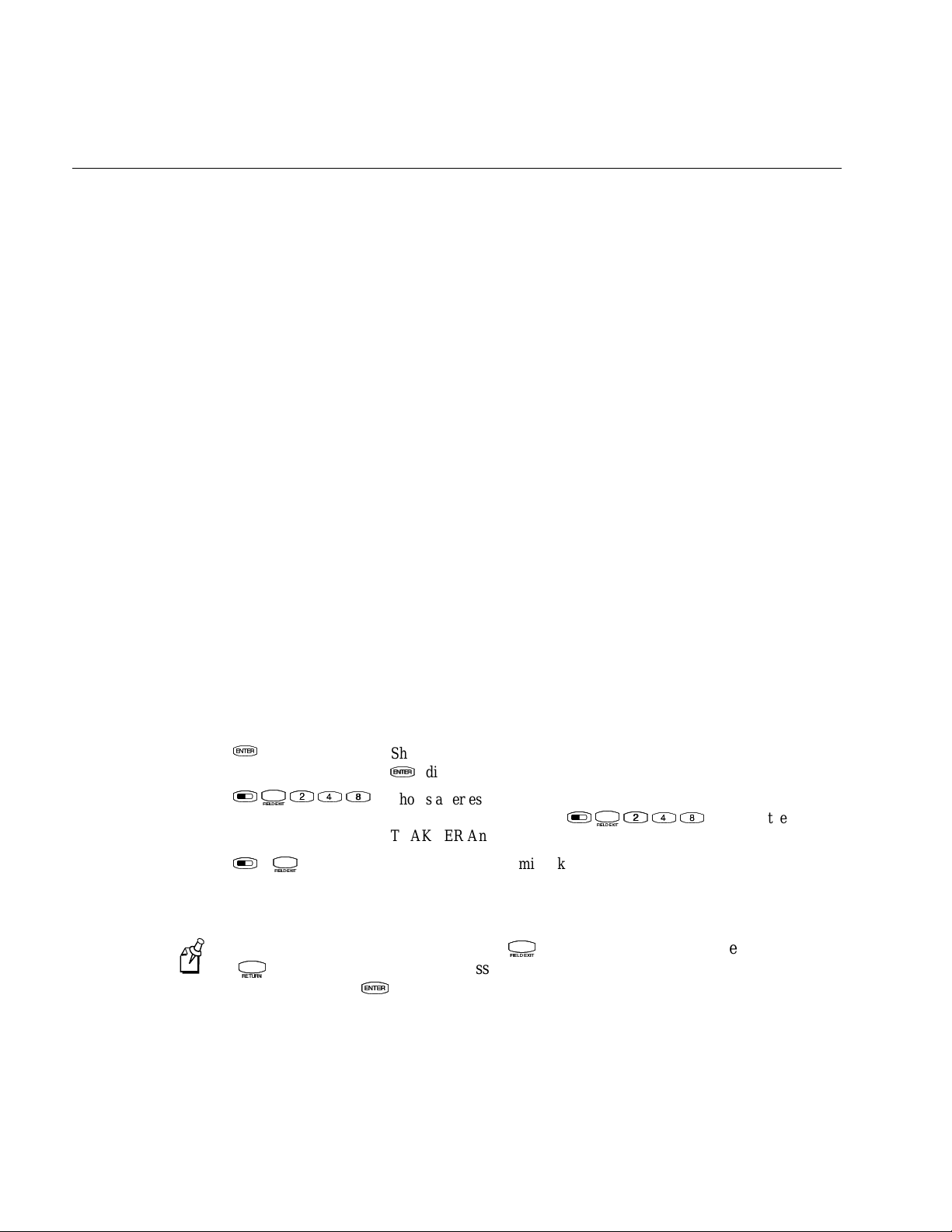
Conventions for Input From a Keypad or Keyboard
This table describes the formatting conventions for input from PC or host computer
keyboards and terminal keypads:
nugget
d39
Convention How to Interpret the Convention
Special text
Italic text Indicates that you must replace the parameter with a value. See
Bold text
V
V
L
T
L
T
L
–
L
Note:
X
(
) on the 39-key keypad to access the TRAKKER Antares 2400 Main Menu. Do
X
T
T
You must use the Field Exit key (
use the Enter key (
Shows the command as you should enter it into the terminal. See
“Conventions for Commands” later in this chapter.
“Conventions for Commands” later in this chapter.
Indicates the keys you must press on a PC or host computer keyboard.
For example, “press Enter” means you press the key labeled “Enter”
on the PC or host computer keyboard.
Shows the key you must press on the terminal. For example, “press
V
” directs you to press the Enter key on the terminal keypad.
V
Shows a series of terminal keys you must press and release in the order
L
T
shown. For example, “Press
TRAKKER Antares 2400 Menu System.”
Shows a series of terminal keys you must press simultaneously. Also,
you must press and hold the keys in the order shown.
T
) on the 57-key keypad or the Return key
T
V
) in this key sequence.
V
L
T
to access the
not
x
Page 11
nugget
*$+*
Change Configuration
*$+*
Name
Bar code (Code 39)
Human-readable
interpretation
243XU099.eps
MAIN MENU
Configuration Menu
Diagnostics Menu
System Menu
About TRAKKER 2400
_` Select item
[Enter] Next screen
[F1] Help
[Esc] Exit
243XU050.eps
File name:
243XU060.eps
d39
Before You Begin
Conventions for Bar Codes
You can scan the bar codes listed in this manual to enter data or perform a command.
The bar code labels in this manual are printed in the Code 39 symbology. Each bar code
includes the name and human-readable interpretation. For example:
The asterisks (*) at the beginning and end of the human-readable interpretation are the
start and stop codes for a Code 39 bar code label. If you are using a bar code printing
utility, it may automatically supply the asterisks as the start and stop code, so that you
only need to type the actual text of the command. You can also create and print
configuration labels and reader command labels in Code 93, which has its own start and
stop codes.
Conventions for Software Screens and Messages
This manual includes illustrations that represent how the Trakker Antares 2430 and
2435 terminals display software screens and messages. Here are two examples:
The TRAKKER Antares 2400 Menu System software screens are 16 lines by 20
characters (like the Main Menu screen example shown here). These screens are
centered and formatted to fit on the 2430 and 2435 screens.
xi
Page 12

Trakker Antares 243X Hand-Held Terminal User’s Manual
Conventions for Commands
This manual includes sample commands that are shown exactly as you should type
them on your terminal or network device. The manual also describes the syntax for
many commands, defining each parameter in the command. This example illustrates the
format conventions used for commands:
To send a configuration command from the DCS 30X, use this syntax:
$+
command[command
where:
$+ is the Change Configura tion command.
]...[
command n
nugget
]
d39
command
is a configuration command. For example, BV is the command to set the
Beep Volume on the terminal. Enter the command BV0 to turn off the
beep volume. You can include multiple configuration
parameters in the command to configure the terminal.
command
This table defines the conventions used in the example:
Convention Description
Special font
Italic text
[ ] Brackets enclose a parameter that you may omit from the command. Do
Required parameters If a parameter is not enclosed in brackets [ ], the parameter is required.
where This word introduces a list of the command’s parameters and explains
Commands appear in this font. You enter the command exactly as it is
shown.
Italics indicate a variable, which you must replace with a real value,
such as a number, file name, keyword, or command.
not include the brackets in the command.
You
command will not execute correctly.
the values you can specify for them.
include the parameter in the command; otherwise, the
must
Other Intermec Manuals
You may need additional information when working with the 243X in a data collection
system. Please visit our Web site at www.intermec.com to download many of our
current manuals in PDF format. To order printed versions of the Intermec manuals,
contact your local Intermec representative or distributor.
xii
Page 13

1
Learning About the Terminal
Page 14

Blank page
Page 15
nugget
This chapter introduces the Trakker Antares 2430 and 2435 hand-held terminals and
their features including the batteries, memory, drives, and input devices. It also
describes how to start using the 243X.
Learning About the Terminal
39
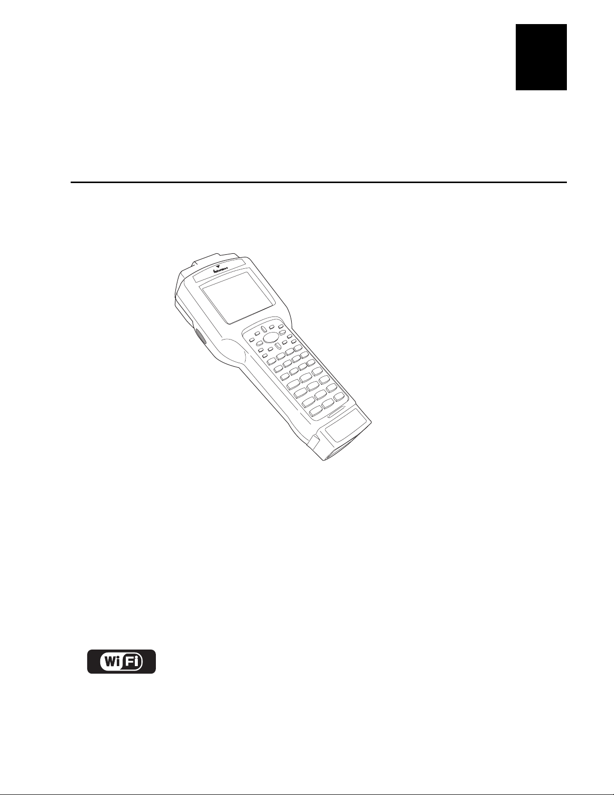
What Are the Trakker Antares 243X Terminals?
The 2430 and 2435 are ergonomic hand-held data collection terminals. You can use
these programmable terminals to run custom applications or terminal emulation
applications.
2435
1
243XU010.eps
2430 The 2430 is a programmable data collection terminal that runs custom batch
applications. The 2430 has a flash drive to store applications and files and an integrated
input/output (I/O) port to transmit data to and accept data from a host computer or other
serial device using RS-232 communications. The versatile display features of the 2430
allow you to resize the screen based on operator preference and work environment.
2435 The 2435 has all of the same functionality as the 2430 with the additional ability
for real-time communications through an RF network. The 2435 can communicate with
a host either through the access points and the DCS 30X or directly through the access
points. The 2435 can also run client/server application s, TE 2000 terminal emulation
applications, and Data Collection Browser (dcBrowser), which lets you run Webbased applications.
™
The 2435 with an IEEE 802.11b radio (with radio firmware 4.52/6.04 and higher)
installed is Wi-Fi certified for interoperability with other 802.11b w ire le ss LAN
devices.
1-3
Page 16
Trakker Antares 243X Hand-Held Terminal User’s Manual
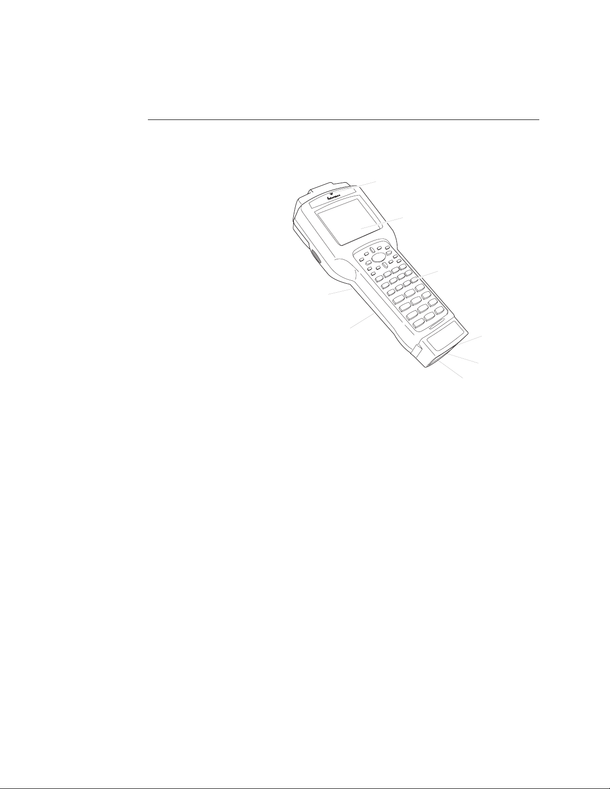
2435
Rechargeable
battery pack
CGA-compatible
screen
Handstrap
Keypad
243XU001.eps
Good Read
LED
Integrated
I/O connector
Docking
connector
Input device
connector
Learning About the 243X’s Features
The 243X is designed to make data collection easy and includes these features:
CGA-compatible screen
The screen is a backlit
LCD that is configurable
up to 21 lines by 31
characters. The screen
also supports doublebyte characters, userprogrammable fonts,
and bitmap graphics.
Good Read LED
and audio signals
The Good Read LED
indicates the status of bar
code scanning. The 243X
also has status icons and
a beeper that provide
you with feedback for
terminal operations.
nugget
39
Keypad There are two
keypad options with different overlays. The 243X ships with a keypad and an overlay
that supports the type of application that you ordered.
Integrated I/O connector The 6-pin connector acts as a serial port or power supply.
You can connect the 243X to a serial device with the serial adapter cable. You can also
connect the 243X to the external power supply with the external power adapter cable.
Input device connector The 9-pin connector on the connector module allows you to
connect an input device to the 243X. Depending on the type of connector module you
choose, the terminal supports either non-decoded input devices or decoded input
devices.
Docking connector The docking connector allows you to insert the 243X into the
vehicle dock accessory.
Handstrap The elastic handstrap attaches to the back of the terminal to let you hold the
terminal easily and securely for long periods of use.
Rechargeable battery pack and backup power source The 243X uses a rechargeable
lithium-ion battery pack as its main power source. The terminal has a backup power
source that maintains the terminal’s status, memory, and real-time clock (for up to 15
minutes) when the battery pack is changed.
Internal Antenna (2435 only) The 2435 uses an internal antenna that supports RF
communications.
1-4
Page 17

nugget
Learning About the Terminal
39
Options for the Terminals
These options are available for the 2430:
Programmable terminal with 57-key alphanumeric or 39-key function numeric
•
keypad and overlays for U.S. English or International languages
Integrated laser scanner (standard range, long range, or extra long range)
•
2MB or 4MB extended storage drive, used for custom applications or files
•
Standard connector module (supports non-decoded tethered scanners) or serial
•
connector module (supports decoded tethered scanners)
Trakker Antares ROM-DOS support
•
These options are available for the 2435:
Programmable terminal with 57-key alphanumeric or 39-key function numeric
•
keypad and overlays for U.S. English or International languages
Integrated laser scanner (standard range, long range, or extra long range)
•
Standard connector module (supports non-decoded tethered scanners) or serial
•
connector module (supports decoded tethered scanners)
1
IBM 3270, IBM 5250, and VT100/220/320 and ANSI TE 2000 terminal emulation
•
application with 57-key alphanumeric or 39-key function numeric keypads
UDP Plus (DCS 30X network) or TCP/IP network protocol
•
dcBrowser application
•
Trakker Antares ROM-DOS support
•
WLI Forum 2.4 GHz OpenAir radio or IEEE 802.11b radio
•
This manual explains how to use the features and options available on all models of the
Trakker Antares terminals.
For additional help using terminal emulation, see the appropriate TE 2000 manual:
TE 2000 5250 Terminal Emulation Programmer’s Guide
•
TE 2000 3270 Terminal Emulation Programmer’s Guide
•
TE 2000 VT/ANSI Terminal Emulation Programmer’s Guide
•
977-055-005)
For additional help using dcBrowser, see the documentation that ships with your
DCS 30X, the dcBrowser gateway software, or the
User’s Guide
(Part No. 070011).
Data Collection Browser Client
(Part No. 977-055-004)
(Part No. 977-055-003)
(Part No.
1-5
Page 18
Trakker Antares 243X Hand-Held Terminal User’s Manual
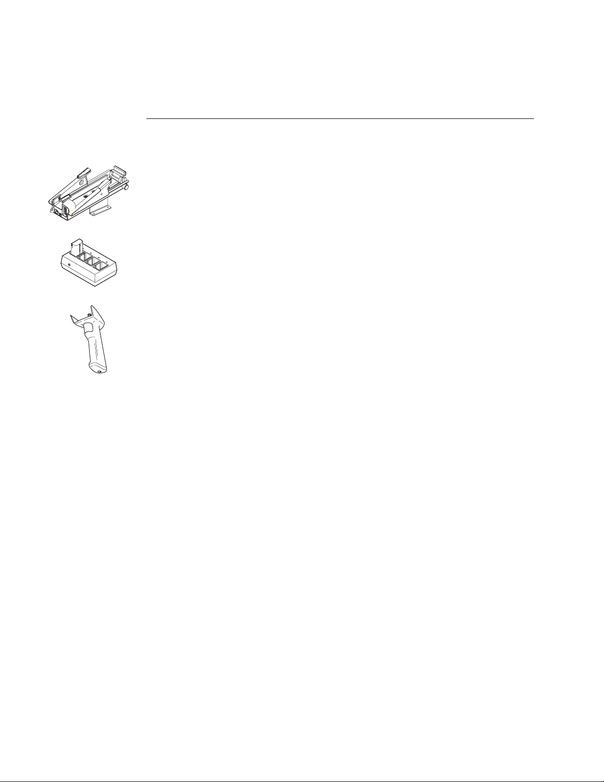
Accessories for the Terminals
You can use these accessories (sold and ordered separately) with the 243X:
Vehicle Dock The vehicle dock is available in a standard model (Part No. 071805)
and a powered model (Part No. 071695). This accessory allows you to easily mount
the 243X to a variety of surfaces.
Z2400 Battery Charger The battery charger (Part No. Z2400A) lets you charge up to
four lithium-ion battery packs at one time. The battery charger senses when a battery
pack is fully charged and will not overcharge it, ensuring long and consistent battery
pack life.
Handle The detachable pistol-grip handle (Part No. 067802) provides a convenient
way to hold the terminal and use trigger-activated scanning.
External Power Supply The external power supply (Part No. 065236) allows you to
power the terminal and charge the battery pack. The power supply comes with a North
American power cord. If you are using the terminal outside North America, you need
to purchase the appropriate power cord for your local power supply.
nugget
39
External Power Supply Adapter Cable The external power supply adapter cable (Part
No. 071776) is shipped with the 243X. Use this cable to connect the 243X to the
external power supply.
Serial Adapter Cable The serial adapter (Part No. 216-807-001) allows the 243X to
communicate with a host computer or other serial device through the serial port.
Cloning Cable The cloning cable (Part No. 216-909-001) allows you to connect two
243X terminals so that you can use the clone application to copy configuration
parameters from one 243X to another 243X.
1-6
Page 19
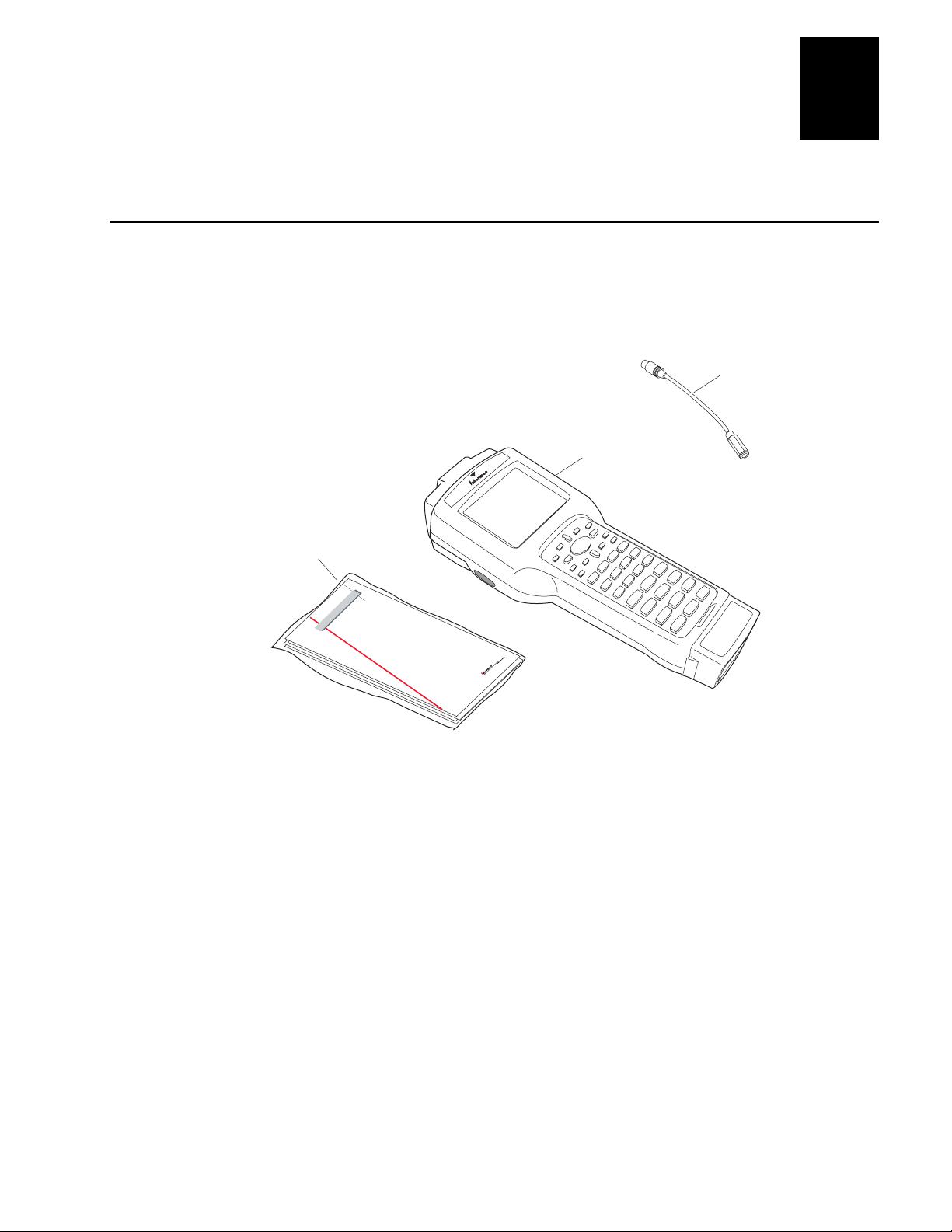
Unpacking the Terminal
5020
Information
packet
243XU0013.eps
2430 or 2435
hand-held
terminal
External power supply
adapter cable
Getting Started Guide
L
o
ca
l A
re
a
S
yste
m
s D
iv
is
ion
Trackker Anteres
243X Hand-Held Termianl
2435
When you remove the 243X from its box, save the box and shipping material in case
you need to ship or store the terminal.
The terminal shipping box contains:
nugget
39
Learning About the Terminal
1
2430 or 2435 hand-held terminal
•
External power supply adapter cable
•
243X quick start guide
•
Manual safety supplement (Important 243X Information!)
•
Handstrap (attached to the back of the 243X)
•
1-7
Page 20
Trakker Antares 243X Hand-Held Terminal User’s Manual
nugget
Using the Terminal’s Battery Pack
Warning
The lithium-ion battery pack that is used in this device may present a fire or chemical
burn hazard if it is mistreated. Do not disassemble it, heat it above 100ºC (212ºF) or
incinerate it.
Avertissement
Le paquet de piles d’ions de lithium qui est utilisé dans cet appareil peut presenter un
risque feu ou un risque chimique de brûlure s’il est maltraité. Il ne faut pas le
désassembler, le réchauffer à une température plus élevée que 100o C (212o F) ou
l’incinérer.
The main power source for the 243X is a lithium-ion battery pack. When you change
the battery pack, a backup power source maintains the terminal status, memory, and
real-time clock for at least 15 minutes. Follow these tips to get the best battery
performance and life possible:
39
Do not press
Note:
Keep a spare, fully charged battery pack on hand.
•
Keep a charged battery pack installed in the terminal to maximize the backup power
•
source’s life and so you can continue to operate the terminal without interruption.
If the terminal turns off due to a low battery, do not turn the terminal back on.
•
Replace or charge the battery pack before you continue using the terminal.
F
when there is no battery pack installed in the terminal.
F
Determining When the Battery Pack Is Low
The battery pack is the main power source for the terminal, and it charges the backup
power source when required. If the battery charge goes low, you need to replace it with
a charged battery pack or charge the battery pack as soon as possible.
There are two ways to determine if the battery pack is low:
The Battery status icon turns on and the terminal beeps once every 15 seconds. For
•
help using the status icons, see “Learning About the Status Icons” on page 1-18.
Check the status of the battery pack using the Battery/PIC Status diagnostic test. For
•
help, see Chapter 4, “Running Diagnostics,” in the Trakker Antares 2400 Family
System Manual (Part No. 071389).
1-8
While the battery is charging, do not use this diagnostic test to determine
Note:
when the battery is fully charged. To determine when the battery is fully charged,
use the status LEDs on the battery chargers.
Page 21
nugget
Handstrap
hook
243XU011.eps
39
Learning About the Terminal
1
Charging the Battery Pack
You must fully charge the battery pack before you can use the terminal.
To charge the battery pack
Place the battery pack in an empty slot in the battery charger. The battery pack fully
•
charges in 3 to 4 hours. For help, see the documentation that came with your
charger.
Install the battery pack in the terminal. For help, see the next section, “Installing the
•
Battery Pack.” Connect one end of the AC power supply adapter cable to the AC
power supply, and connect the other end of the AC power supply adapter cable to
the power port on the 243X. The battery pack is fully charged in about 3 to 4 hours.
You can also use the powered vehicle dock (Part No. 071695) (sold and ordered
separately) connected to an external power supply to charge the battery. For help, see
Trakker Antares 243X Vehicle Dock Installation Instructions
the
Warning
Replace the battery pack with Part No. 068537 only. The use of any other battery
pack may present a risk of fire or explosion.
(Part No. 071793).
Avertissement
Remplacez le bloc-batterie par la pièce réf. n° 068537 seulement. L’utilisation de tout
autre bloc-batterie présente un risque d’incendie ou d’explosion.
Contact your local Intermec sales representative for a replacement battery pack.
DISPOSE OF USED BATTERY PACKS PROMPTLY. KEEP THEM AWAY FROM
CHILDREN.
Installing the Battery Pack
Do not press
Note:
To install the battery pack
1. The 243X ships with the handstrap
installed. Before you install the
battery pack, you must remove the
handstrap. Rotate the handstrap hook
90 degrees, and unhook it from the
243X.
F
when there is no battery pack installed in the terminal.
F
1-9
Page 22
Trakker Antares 243X Hand-Held Terminal User’s Manual
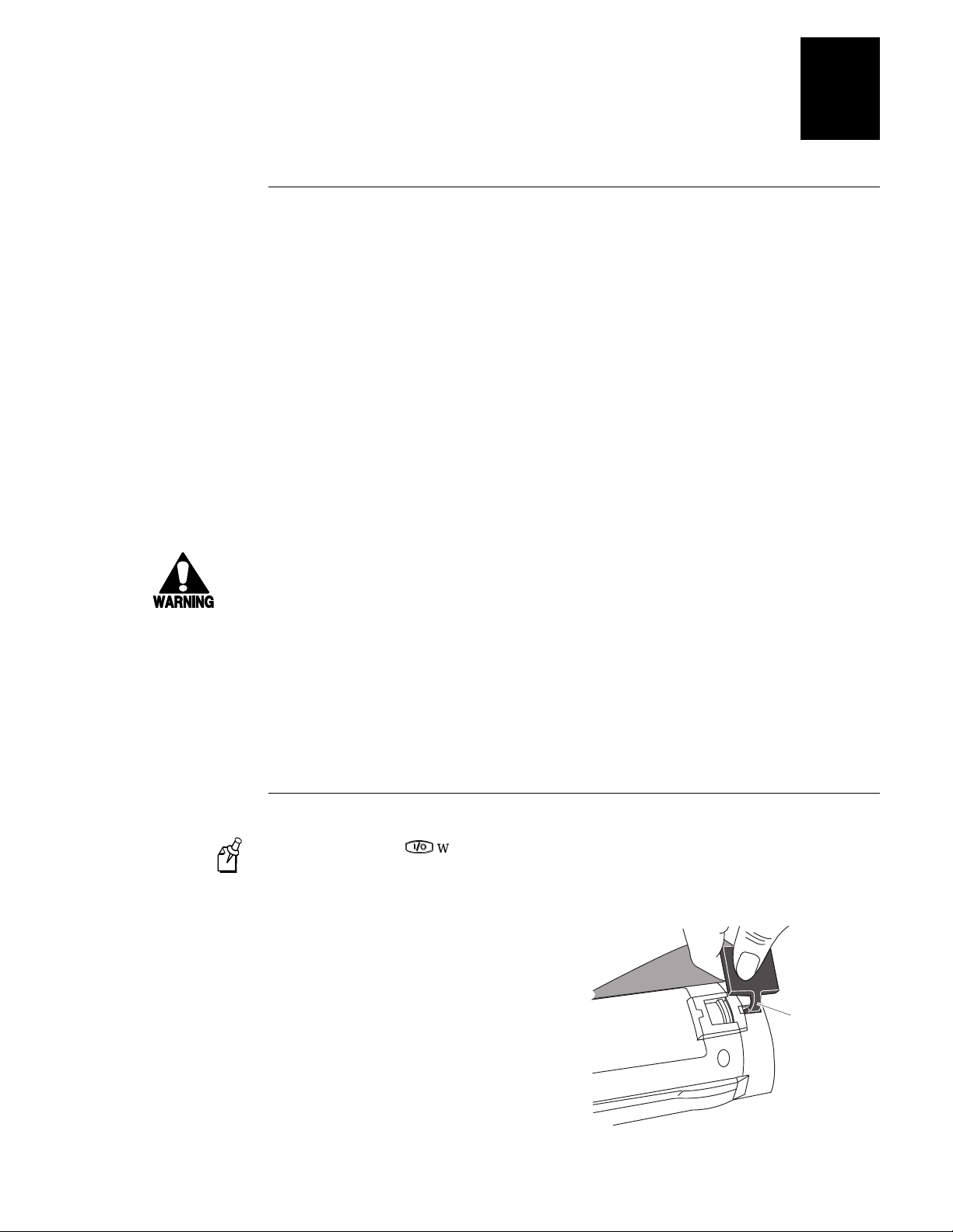
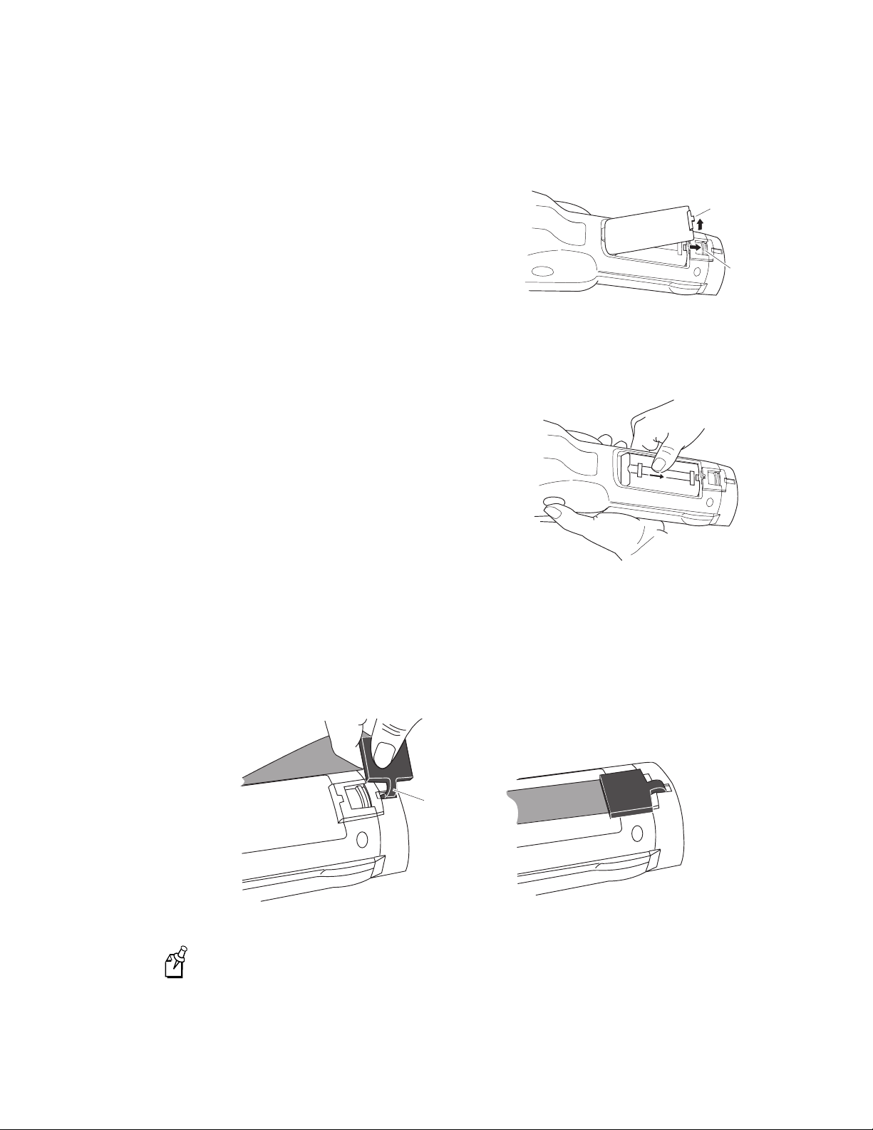
2. Open the battery door.
a. Push down on the battery door latch
and slide it toward the bottom end of
the 243X.
nugget
39
b.
b. Lift up the bottom edge of the
battery door to remove it. You may
need to pry the door open with a
pointed object. Remove the foam
243XU015.eps
insert if necessary.
3. Place the battery pack into the battery compartment with the contacts pointed
toward the bottom of the 243X.
4. Push the battery pack down until it locks
into the connectors in the battery
compartment.
5. Insert the top edge of the battery door into
the top of the battery compartment. Push
the door down to close it over the battery
compartment.
6. Push the battery door latch up and slide it
243XU005.eps
toward the top end of the 243X to lock the
door in place.
The 243X initializes after you install a charged battery pack. The green LED above
the screen turns on briefly.
7. Attach the handstrap by inserting the handstrap hook as shown and rotating the
handstrap hook 90 degrees toward the top of the terminal.
a.
1-10
Handstrap
hook
243XU002.eps
The handstrap is most effective if it crosses the entire back of the hand and not
Note:
just the fingers.
Page 23
nugget
Learning About the Terminal
39
Managing Battery Power
To maximize the life of the battery pack, use these power management features.
Situation Ways to Save Battery Power
1
You are operating the terminal
and the Battery status icon
turns on.
You are not using the terminal
for 5 minutes or longer.
You are goin g to store the
terminal for more than a day.
Using the Keypad
Press
F
to turn off the terminal. Remove the battery pack
F
and insert another fully charged battery pack. You must insert
another fully charged battery pack within 15 minutes of
removing the old battery pack or you may lose data.
Or, if you wa nt to contin ue using the te rminal and you do not
have another battery pack, insert the terminal into the
powered vehicle dock. The vehicle dock must be connected to
an external power supply.
Make sure the Battery status icon is not on. Press
off the terminal.
Or, use the Automatic Shutoff feature. Automatic shutoff
turns off the terminal when there is no activity on the terminal
for the length of time you set. For help, see “Automatic
Shutoff” in Chapter 6 of the 2400 Family system manual.
Save your data and end your terminal session to minimize the
risk of data loss. Press
fully charged battery pack before you store the terminal.
F
to turn off the terminal. Insert a
F
F
F
to turn
The 243X has the following keypad options and overlays:
•
57-key alphanumeric keypad
•
39-key function numeric keypad
•
TE 2000 terminal emulation overlays
The 57-key alphanumeric keypad and the 39-key function numeric keypad are available
in U.S. English and International. The International option supports French, German,
Italian, Portuguese, and Spanish. Although the keypads are smaller than standard PC or
terminal keyboards, you can use special keys to access all the keys and functions that
you need.
Both keypad options support overlays for TE 2000 3270, TE 2000 5250, and TE 2000
VT/ANSI. When you order a TE 2000 application, you also receive the appropriate
TE 2000 keypad overlay. Each TE 2000 keypad overlay is similar to the standard U.S.
English keypad overlay, but it contains additional keys that are available on an IBM
3270, IBM 5250, or VT/ANSI keyboard. For additional help using terminal emulation,
see the appropriate TE 2000 manual.
1-11
Page 24
Trakker Antares 243X Hand-Held Terminal User’s Manual
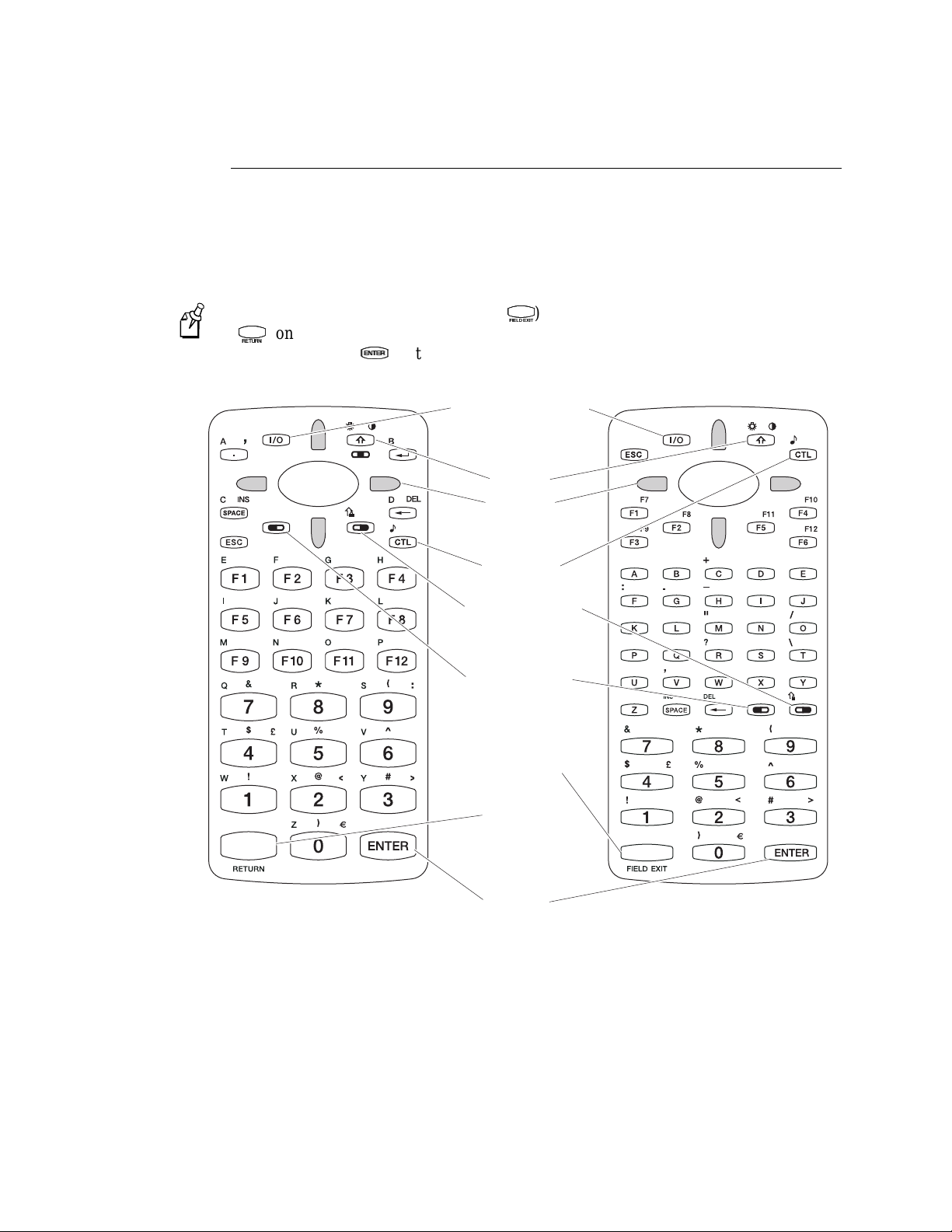
Finding the Special Keys
Before you use the terminal’s keypad, make sure you are familiar with the different
types of keys on the keypad. You need to use these special keys on all keypad options.
The special keys that you use to type characters or perform functions are explained in
the next sections.
nugget
39
You must use the Field Exit key (
Note:
X
(
) on the 39-key keypad to access the TRAKKER Antares 2400 Main Menu. Do
X
use the Enter key (
V
) in the key sequence to access the main menu.
V
Suspend resume key
T
) on the 57-key keypad or the Return key
T
Shift key
Arrow key
(4 places)
Control key
Function right key
Function left key
Field exit key
Return key
not
1-12
39-key U.S. English
function numeric keypad
Enter key
57-key U.S. English
alphanumeric keypad
243XU034.eps
Page 25
nugget
39
Learning About the Terminal
1
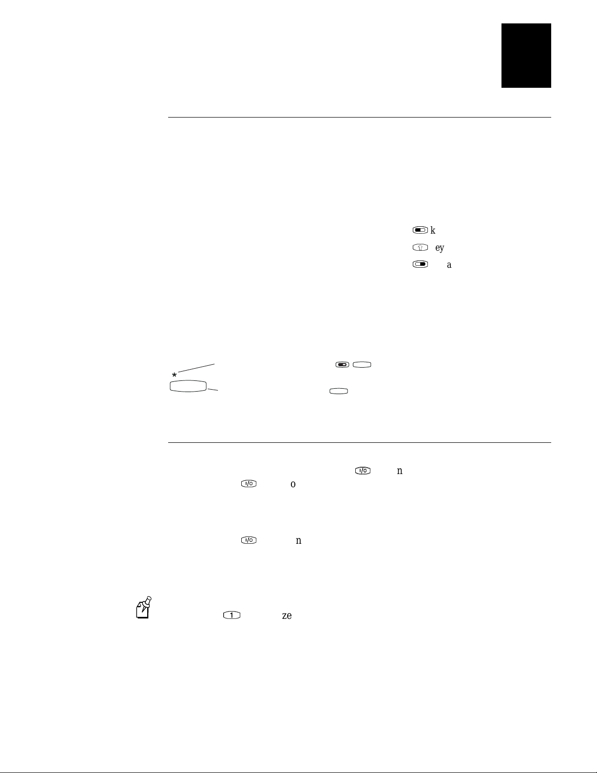
Typing the Characters Printed on the Keypad
The keypads are easy to use. Characters, symbols, and functions are printed in four
places on or above the keys. The keys are also color-coded to make it easier to
remember key combinations.
Position on the Keypad Color on Overlay To Type the Character
Printed on the key Press the key.
Left side above the key Orange Press the
Centered above the key Pink
Right side above the key Blue
To learn how to type characters, use the following illustration and example from the
57-key U.S. English alphanumeric keypad.
Typing characters using the 57-key U.S. English alphanumeric keypad
To type the * character, press .
8
To type the number 8, press .
8
243XU017.eps
Press the
Press the
8
L
key and then the key.
L
W
key and then the key.
W
R
key and then the key.
R
Using the Suspend/Resume Key
The terminal’s Suspend/Resume key is the
F
When you press
goes into a Suspend mode. In Suspend mode, the terminal continues to power all
memory and turns off the power to most of the hardware. This mode is referred to as
“off” in the rest of this manual.
to turn off the terminal, the terminal does not actually shut off but
F
F
key on the top left side of the keypad.
F
F
When you press
was when you turned it off, or the terminal boots and restarts your application. Resume
is controlled through the Resume Execution command. For help, see “Resume
Execution” in Chapter 6 of the 2400 Family system manual.
Note:
The terminal displays the boot menu the first time you turn it on. At the boot
menu, press
to turn on the terminal, the terminal either resumes exactly where it
F
to initialize the firm ware and boot the terminal.
1-13
Page 26
Trakker Antares 243X Hand-Held Terminal User’s Manual
Using the Modifier Keys
The keypad does not have a physical key for every character and function available.
R
R
C
,
C
L
), Function Right (
L
C
,
, or
C
W
, or
W
You use the Function Left (
keys to access characters or perform functions that do not have a physical key on the
keypad. You also use the Shift key to type uppercase alphabetic characters.
L
L
L
L
R
,
R
,
When you press
another key. The Modifier Key status icon on the right side of the terminal’s screen
turns on to remind you that the key is being held in the buffer. When you press another
key, the key combination is entered into the te rminal. The Modifier Key status icon
turns off unless the second key that you pressed is another modifier key that is different
from the first one that you pressed. For help using the status icons, see “Learning About
the Status Icons” on page 1-18.
To flush the
just press the key again. The Modifier Key status icon turns off.
To use the Function Left, Function Right, Control, and Shift keys
nugget
W
, the key is held in a buffer until you press
W
key from the buffer without performing any action,
39
R
), Control (
R
C
), and Shift (
C
W
W
)
L
R
1. Press
2. Press the second key. The Modifier Key status icon turns off.
For example, to type the Euro symbol (
Key status icon turns on. Press
symbol appears on the screen.
L
,
R
,
C
C
, or
W
. The Modifier Key status icon turns on.
W
¼ RQ D NH\ NH\SDG SUHVV
. The Modifier Key status icon turns off, and a Euro
R
. The Modifier
R
Capitalizing All Characters
To type all alphabetic characters as uppercase letters, you can
W
press
•
enable the Caps Lock feature. For help, continue with the next procedure.
•
Note:
Caps Lock feature is enabled.
use the Keypad Caps Lock configuration command. For help, see “Keypad Caps
•
Lock” in Chapter 6 of the 2400 Family system manual.
before every letter you type.
W
You cannot access the TRAKKER Antares 2400 Menu System while the
1-14
Page 27
To enable Caps Lock
nugget
39
Learning About the Terminal
1
1. Press
2. Press
3. Type an alphabetic character. The letter appe ars as an upperc a se cha racte r on the
To type a lowercase letter with Caps Lock enabled
•
To disable Caps Lock
1. Press
2. Press
3. Type an alphabetic character. The letter appears as a lowercase lette r on the
L
. The Modifier Key status icon turns on.
L
R
. The Caps Lock icon turns on and the Modifier Key icon turns off.
R
terminal’s screen. The Caps Lock feature remains on until you disable it.
W
Press
terminal’s screen.
and an alphabetic character.
W
L
. The Modifier Key status icon turns on.
L
R
. The Caps Lock and Modifier Key status icons turn off.
R
Using the International Keypads
You can order the 243X with an International keypad overlay that supports French,
German, Italian, Portuguese, and Spanish. Like the U.S. English keypads, you use the
international keypad to enter all the characters printed on or above the keys. For help,
see “Typing the Characters Printed on the Keypad” on page 1-13. You can also use the
international keypad to type characters with diacritical marks.
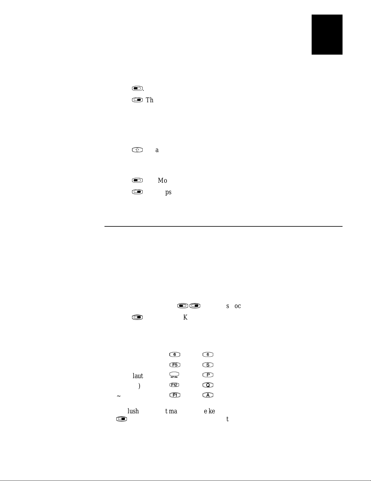
To type characters with a diacritical mark
L
1. (39-key ke yp a d ) Press
2. Press
3. Press the key that the diacritical mark appears above.
R
. The Modifier Key status icon turns on.
R
To Type 39-Key 57-Key
ˆ (circumflex)
` (grave)
¨ (umlaut)
´ (acute)
~ (tilde)
To flush the accent mark from the keypad buffer without entering any key, press
R
twice. The Modifier Key status icon tu rns off.
R
K
K
X
X
@
@
G
G
L
R
. The Caps Lock status icon turns on.
R
6
6
3
3
4
4
$
$
1-15
Page 28
Trakker Antares 243X Hand-Held Terminal User’s Manual
4. Enter one of the following types of characters:
To accent a lowercase character
•
nugget
39
(39-key ke yp a d ) Press
(57-key keypad) Press the character.
To accent an uppercase character
•
(39-key keypad) Press the character.
(57-key ke yp a d ) Press
(57-key keypad) To type the accent mark by itself, press the
•
(39-key keypad) The accented character or accent mark appears on the screen, the
Modifier Key status icon turns off, and the Caps Lock status icon remains on.
(57-key keypad) The accented character or accent mark appears on the screen and
the Modifier Key status icon turns off.
If you are using a 39-key keypad, you must use the Left Arrow key (
Note:
the Right Arrow key (
respectively.
If you try to accent a character and the resulting character is not supported on the
terminal, the plain (unaccented) character appears on the terminal screen. For a
complete list of the international characters available in the terminal font, see
Appendix C, “International Character Support,” in the 2400 Family system manual.
W
, and then press the character.
W
W
, and then press the character.
W
S
key.
S
B
) to type an accent mark above the letters “U” and “Y”
B
A
A
) and
1-16
Using the TE 2000 Keypads
The 243X supports TE 2000 VT100/220/320/340 and ANSI, TE 2000 5250, and
TE 2000 3270. When you order a TE 2000 application, you also receive the appropriate
TE 2000 keypad overlay. TE 2000 keypad overlays let you enter the same keys that you
can enter from a VT/ANSI keyboard, an IBM 5250 keyboard, or an IBM 3270
keyboard.
Like the 39-key function numeric and the 57-key alphanumeric keypad overlays, the TE
2000 keypad overlay lets you enter all the characters printed on or above the keys. For
help, see “Typing the Characters Printed on the Keypad” on page 1-13. The TE 2000
keypad overlays also come with the same special keys that are on the 39-key function
numeric and the 57-key alphanumeric keypad overlays. For help, see “Finding the
Special Keys” on page 1-12.
For more help, see the appropriate TE 2000 manual.
Page 29
Using the Screen
You can use the terminal’s screen to view data, run applications, monitor the terminal’s
status, and perform many other functions. The CGA-compatible screen is a backlit LCD
that is configurable up to 21 lines by 31 characters. The screen also supports doublebyte characters, user-programmable fonts, and bitmap graphics.
The 243X screen has versatile display features that allow you to resize the screen based
on operator preference and work environment. For help, see “Display Spacing” in
Chapter 6 of the 2400 Family system manual. Depending on the application, you can
also use the viewport feature to move around a full 25-line by 80-character screen.
nugget
39
Learning About the Terminal
1
W
W
The Shift key is built into the terminal’s keypad. You can use the Shift key to
turn the backlight on and off.
•
adjust the display contrast.
•
When you use this key to change the backlight or contrast, these changes are not saved
permanently in flash memory.
To turn the backlight on and off
L
L
W
W
.
L
W
L
W
Press
•
Turn the backlight on to see the terminal’s screen more easily in dimly lit environments.
The backlight stays on for the length of time set in the Display Backlight Timeout
command as long as there is no keypad or scanning activity or until you press
again. For more information, see “Display Backlight Timeout” in Chapter 6 of the 2400
Family system manual.
You use the battery power at a faster rate with the backlight turned on.
Note:
To change the display contrast
R
R
W
W
.
R
W
R
, it makes the display contrast one level darker. There are
W
R
W
R
W
Press
•
Each time you press
eight contrast levels. If the contrast is at the darkest level and you press
contrast changes to the lightest contrast level. For help, see “Display Contrast” in
Chapter 6 of the 2400 Family system manual.
, the
1-17
Page 30
Trakker Antares 243X Hand-Held Terminal User’s Manual
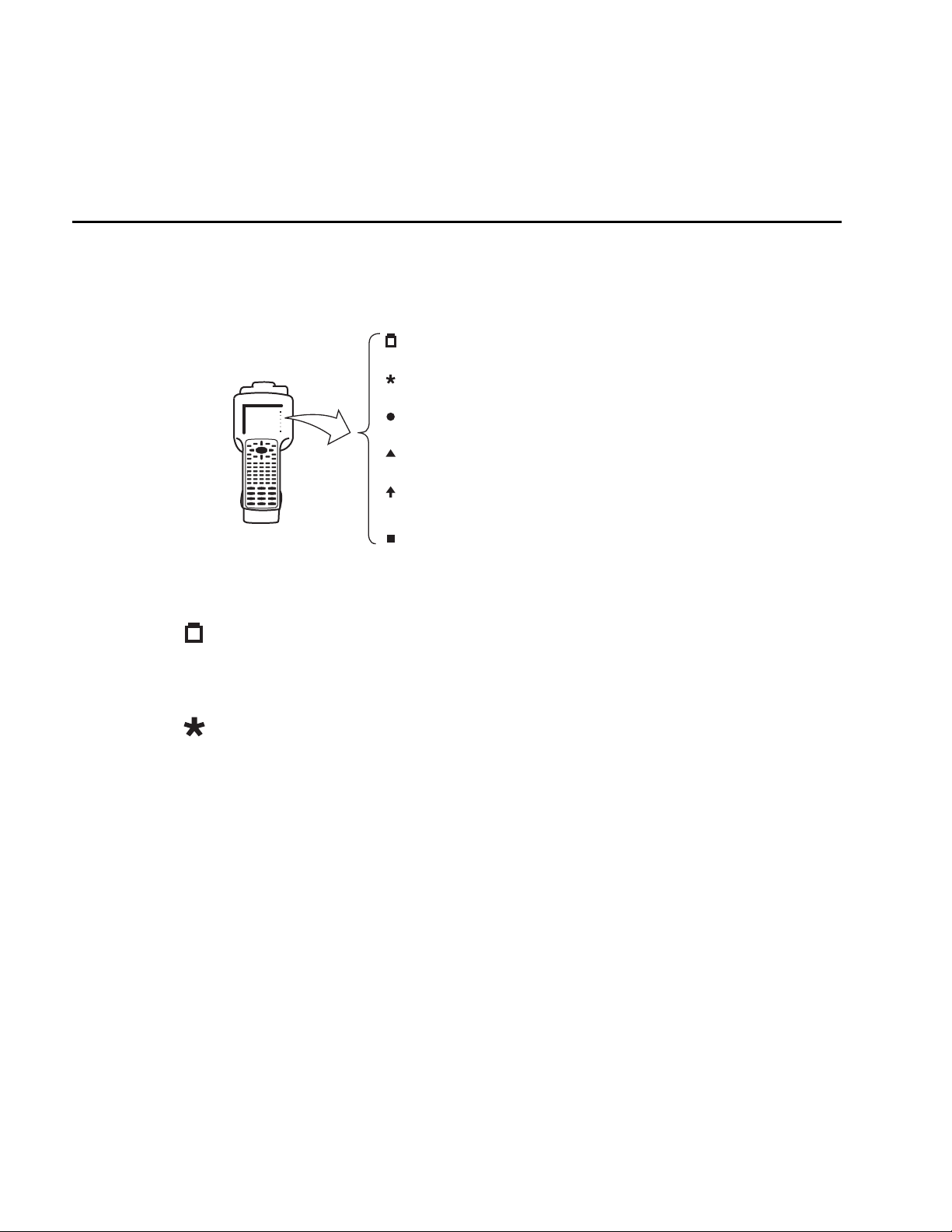
Battery
Network Connect
Network T r ansmit
Modifier Key
Caps Lock
User Defined
243XU032.eps
Learning About the Status Icons
You can use the status icons on the right side of the screen to monitor the status of
battery power, special keys, and network communications. The status icons only turn on
to indicate the current status. When the 243X is off, the icons are also off.
nugget
39
Battery This icon remains off when you have a charged battery pack in the terminal.
The icon turns on when there is a low battery charge and the terminal is on. When the
terminal beeps once every 15 seconds, replace the battery pack with a charged battery
pack or charge the battery pack as soon as possible.
Network Connect This icon tells you if the 2435 is connected to your network. The
Network Connect status icon may be off, blinking, or on.
Protocol Status Icon Off Status Icon Blinks Status Icon On
TCP/IP Not connected. Nothing Connected to an
access point.
UDP Plus Not connected. Connected to an
access point, but
Connected to a
DCS 30X.
not to a DCS 30X.
When the Network Connect icon is off, you are not connected to the network. Make
sure the Network Activate command is enabled and that the terminal is configured
correctly for your RF network. Make sure that you are in range of an access point.
In a UDP Plus network, this icon is not instantaneously updated, but it does tell you
the communications status the last time data was sent or received from the 2435.
1-18
Page 31

nugget
Network Transmit This icon turns on when data is buffered in the RF network
interface. The data is either waiting to be transmitted to the DCS 30X or host, or
received data has not been accepted by the application on the 2435. When no data is
being buffered in the interface, the Network Transmit icon is off.
Learning About the Terminal
39
1
Modifier Key This icon indicates that one of the modifier keys, such as
enabled. When you press another key, the key combination is available to the
application. The Modifier icon turns off unless the second key that you pressed is
another modifier key that is different from the first one that you pressed.
Caps Lock This icon turns on when you press
L
feature. When you press
If Caps Lock is enabled, this icon remains on until you disable Caps Lock.
User Defined This icon is user defined. You can program this icon to turn on and off
for any task or error within your application.
L
R
again to disable Caps Lock, the icon turns off.
R
Learning About the Audio Signals
The terminal has a beeper that provides you with audio feedback as you use the
terminal. For example, you hear a beep tone each time you enter or scan a valid
command. You can change the beep volume and the beep duration to meet the needs
of your working environment.
When you change the beep volume, you also change the keyclick volume if the Keypad
Clicker command is enabled. The keyclick is the sound that you hear when you press a
key on the terminal.
L
L
R
to enable the Caps Lock
R
W
W
, is
There are three ways to change the beep volume:
L
Press
•
louder. There are five beep volume levels including off. If the volume is at the
loudest level and you press
C
C
Note:
changes are not saved permanently in flash memory. You can save the changes in
flash memory later. For help, see “Exiting Screens and Saving Changes” in
Chapter 2.
Use the TRAKKER Antares 2400 Menu System. From the Main Menu, choose
•
Configuration Menu, then Terminal Menu, and then Beeper.
Use the Beep Volume command. For help, see “Beep Volume” in Chapter 6 of the
•
2400 Family system manual.
C
L
again, the volume changes to the quietest level.
When you use the keypad to change the beep and keyclick volume, the
. Each time you press
C
L
L
L
C
L
C
, the beep volume is turned off. If you press
C
, the beep volume becomes one level
C
L
L
1-19
Page 32

Trakker Antares 243X Hand-Held Terminal User’s Manual
COM1
243XU008.eps
This table lists each beep sequence and describes the situations under which they occur.
Beep Sequence Situation
High beep You entered valid data, you entered a valid command, the terminal
decoded a label, or the terminal decoded the last row of a two-
dimensional bar code.
Three low beeps You entered or scanned an invalid command or data.
Four low beeps You booted the terminal and the power-on self test (POST) was
successful.
nugget
39
Low beep, high
beep, low beep,
high beep
Click You pressed a key and the Keypad Clicker command was enabled. To
Low beep (every
15 seconds)
You booted the terminal and the POST failed. For help, see “Problems
While Operating the Terminal” in Chapter 4.
disable the keyclick, see “Keypad Clicker” in Chapter 6 of the 2400
Family system manual.
The battery pack is low. You must replace or recharge the battery pack.
For help, see “Using the Terminal’s Battery Pack” on page 1-8.
Using the Terminal’s Serial Port
Serial ports, also called COM (communications) ports, are locations from which data
can be passed into and out of the terminal. The 243X supports RS-232 serial
communications.
1-20
Port COM Port Designation for Applications
COM1 Use for serial port communications on the terminal. You can use a serial cable
to connect this terminal to another serial device, such as a modem, a PC, or a
printer. If you have a serial connector module, you can also use the input device
connector as COM1. For help, see “Learning About the Connector Modules” on
page 1-23.
Page 33

nugget
Port COM Port Designation for Applications
Note: The serial/power connector and the input device connector lead to the
same serial port, COM1. Do not connect more than one serial device to the
243X.
RF (NET) Use for RF communications on the 2435. The Trakker Antares PSK functions
use NET to d esignate the RF ne twork port.
Using the Terminal’s Scanner
Warning
Do not look directly into the window area or at a reflection of the laser beam while
the laser is scanning. Long-term exposure to the laser beam can damage your vision.
Avertissement
Ne regardez pas directement la réflexion d’un rayon laser ou dans la fenêtre du laser
lorsque celui-ci est en opération. Si vous regardez trop longtemps un rayon laser, cela
peut endommager votre vue.
39
Learning About the Terminal
1
You can use the scanner to scan and enter bar code data. When you press the Scan
button or one of the side scan buttons, the scanner emits a beam of laser light that is
visible on the bar code label as you scan it. The terminal decodes the bar code and
enters the data or command you scanned.
Note:
The Scan button on the keypad and the side scan buttons on the terminal do not
activate the tethered input device that m ay be connected to the term ina l.
When you unpack the 243X, these three bar code symbologies are enabled:
•
Code 39
•
Code 128
•
UPC/EAN
To scan other bar code symbologies, you must enable them on the 243X. For help, find
the symbology in Chapter 6 of the 2400 Family system manual.
To scan a bar code label with the scanner
1. Press
2. Hold the terminal at a slight angle a few inches from the bar code label. The scanner
F
to turn on the terminal.
F
must be pointing toward the label.
1-21
Page 34

Trakker Antares 243X Hand-Held Terminal User’s Manual
If you have a long range or extra long range scanner, you may need hold the
Note:
terminal further away.
3. Push the Scan button on the keypad or one of the side scan buttons on the terminal.
Direct the beam so that it falls across all bars in the bar code label. When the
terminal successfully reads the label, you will hear a high beep.
Scan button
2435
*2435ROCKSs*
Side scan
button
(2 places)
nugget
39
243XU009.eps
The green Good Read LED turns on when you successfully scan a bar code label
with the integrated scanner or an input device that is connected to the terminal. This
LED turns off after 2 seconds unless you start scanning another label.
4. Release the Scan button.
You can configure scanning options to scan multiple bar code labels without
Note:
pressing the Scan button each time. For help, see “Scanning Options” on page 1-24.
To successfully read a bar code label, the laser beam in the scan module must see all the
bars in a label and a clean, non-printed space, or “quiet zone,” at each end of the label.
*NANCY*
1-22
Quiet zone before and
after bar code
243XU098.eps
Page 35

nugget
Input device
connector
Serial/Power
connector
243XU009.eps
Standard
Connector Module
Input device
connector
Serial/Power
connector
243XU007.eps
Serial
Connector Module
Use the following guidelines to achieve a successful scan:
Hold the terminal so that the scanner is pointing toward the bar code label. Tilt the
•
terminal up or down slightly (20 degrees).
Optimum scan angles vary with the type and print quality of the bar code label, the
•
distance of the scanner from the label, and the lighting in the area.
Do not scan the bar code label “straight on.” In a 2-degree conical “dead zone”
•
directly above the label, the laser beam may reflect back into the scanner window
and prevent the terminal from reading the label. At certain angles and straight on,
you may not see the laser beam.
Learning About the Terminal
39
Learning About the Connector Modules
The 243X has two different connector module options.
1
Standard Connector Module The input device connector on the standard connector
module supports non-decoded input devices. For a list of these input devices, see “Input
Devices and Cables” in Appendix A.
Serial Connector Module The input device connector on the serial connector module
supports decoded input devices. For a list of these input devices, contact your local
Intermec sales representative. You can also use the input device connector to connect to
a serial device. For help, see “Connecting to a Serial Device or Network” on page 1-24.
The serial/power connector and the input device connector lead to the same serial
Note:
port, COM1. Do
The 243X supports different bar code symbologies depending on the type of input
device connected to the terminal. For a list of these symbologies, see “Bar Code
Symbologies” in Appendix A.
connect more than one serial device to the 243X.
not
1-23
Page 36

Trakker Antares 243X Hand-Held Terminal User’s Manual
Input device
connector
Serial/Power
connector
243XU007.eps
Serial
Connector Module
Connecting an Input Device
1. Use the appropriate interface cable to at tach an inpu t device to the input devi ce
connector on the connector module. For a list of supported input devices and cables,
see “Input Devices and Cables” in Appendix A.
2. Configure the Scanner Selection command and select the input device that is
connected to the terminal. For help, see “Scanner Selection” in Chapter 6 of the
2400 Family system manual.
You must configure the Scanner Selection command. If this command is not
Note:
defined for the appropriate input device, the scanner trigger on the input device may
activate the integrated scanne r on the terminal.
Scanning Options
After you connect an input device to the 243X, you can modify the following scanner
command options to meet your needs:
nugget
39
Decode Security
•
Scan Ahead
•
Scanner Mode
•
Scanner Redundancy
•
For more information about these commands, see Chapter 6, “Configuration Command
Reference,” in the 2400 Family system manual.
Scanner Selection
•
Scanner Timeout
•
Scanner Trigger
•
Connecting to a Serial Device or Network
You can physically connect the 243X to a serial device, such as a host computer or
printer, through the serial/power connector using a serial adapter cable. If you have a
serial connector module, you can use either the serial/power connector or the input
device connector to connect to a serial device.
1-24
Page 37

nugget
Drive D or font set
Drive C
Drive E
Drive G
243X030.eps
Drive C
Drive C
Drive D or font set
Drive E
2435
2430
2MB flash drive/
font set
2MB flash drive/
font set
750K flash
drive
750K flash
drive
256K
configurable
RAM drive
256K configurable
RAM drive
Optional 2MB or
4MB extended
storage drive
The serial/power connector and the input device connector lead to the same serial
Note:
port, COM1. Do
connect more than one serial device to the 243X.
not
Learning About the Terminal
39
1
To connect the 243X to a serial device using the serial/power connector
1. Attach a serial device to the serial adapter cable (Part No. 216-807-001) (sold and
ordered separately).
2. Connect the serial adapter cable to the serial/power connector on the 243X.
To connect the 243X to a serial device using the input device connector
1. Attach a serial device to the RS-232 null-modem serial cable (Part No. 070268)
(sold and ordered separately).
2. Connect the serial cable to the input device connector on the 243X.
You can transfer data between the 243X and the serial device. For help, see “Using
Serial Communications on the Terminal” in Chapter 3.
Defining the Terminal’s Drives
The terminals come with the following memory and drives. On each drive, filenames
are customer defined using eight characters with a three-character extension. You
cannot define any subdirectories.
1-25
Page 38

Trakker Antares 243X Hand-Held Terminal User’s Manual
Drive C is a 2MB flash drive. You can use up to 750K of this flash drive to store up to
128 files on drive C. Applications must be stored on drive C. You use standard ANSI C
library interface definitions to access the information on this drive.
Drive D or font set is 2MB drive of flash memory that you can configure as drive D.
Use this flash drive to store large lookup tables and data files. You can store up to 128
files. You can also order the flash memory to come pre-loaded with a double-byte font
set. To configure this flash m emory, see “Flash Memory Configuration” in Chapter 6 of
the 2400 Family system manual.
Drive E is a configurable RAM drive (up to 256K). The contents of this drive are
erased when you boot or reset the terminal. You can store up to 128 files on drive E, and
you can access these files using standard ANSI C functions. By default, the RAM drive
is not configured and the memory is available for programmable (Malloc) memory
allocations. To configure the RAM drive, see “RAM Drive Size” in Chapter 6 of the
2400 Family system manual.
Drive G (optional) is an optional 2MB or 4MB extended storage drive that is only
available on the 2430. Use this drive to store large lookup tables and data files. You can
store up to 128 files on drive G, and you can access these files using standard ANSI C
functions.
nugget
39
Malloc/free memory On the terminals, applications are customer defined. You have
512K total RAM that you can use for the application execution space. You can also
configure this RAM to be the RAM drive (up to 256K). The remaining RAM is the
Malloc/free memory pool.
Application
execution space
+RAM drive
(drive E)
+ Malloc/free
Using the Terminal for the First Time
Before you can use the 243X for the first time, you must perform certain steps, such as
setting the time and date. You can find this information throughout this user’s manual.
However, if you want to start using the terminal immediately, see the Trakker Antares
243X Hand-Held Terminal Quick Start Guide (Part No. 071792).
To use the 243X for the first time
1. Unpack the terminal and documentation.
2. Charge and install the battery pack (sold separately). For more information about
batteries, see “Using the Terminal’s Battery Pack” on page 1-8.
= 512K RAM
memory pool
1-26
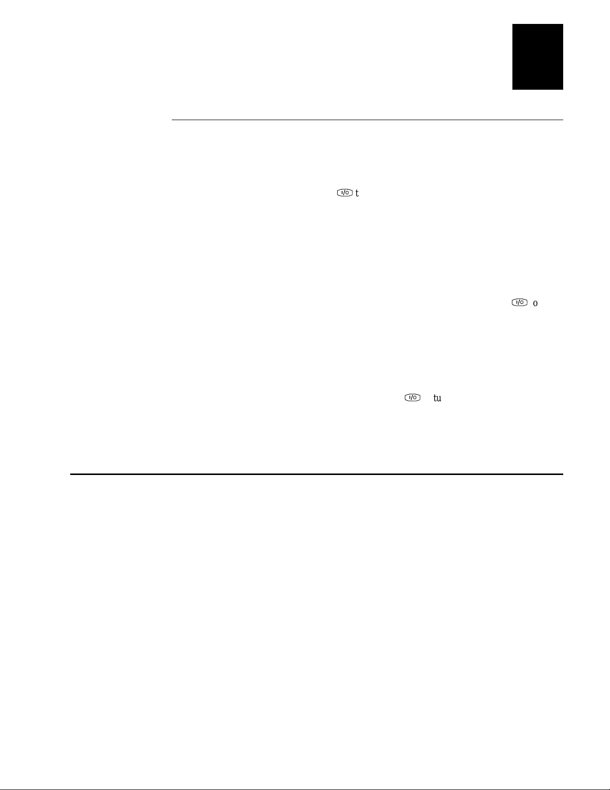
3. Press
4. (Optional) Set the time and date. For help using the TRAKKER Antares 2400 Menu
F
to turn on the terminal. For more information about the keypad, see
F
“Using the Keypad” on page 1-11.
System, see “Configuring the Terminal With the Menu System” in Chapter 2.
Page 39

nugget
5. Configure the serial port par ameters. For more information, see “Using Serial
Communications on the Terminal” in Chapter 3.
6. (2435 only) Configure the RF parameters. For more information, see “Using RF
Communications on the Terminal” in Chapter 3.
7. Enable the bar code symbologies that you want to be able to scan. For more
information, see Chapter 6, “Configuration Command Reference,” in the 2400
Family system manual.
8. Exit the menu system and save your configuration changes to flash memory. For
help, see “Exiting the Menu System” in Chapter 2.
When you are done with these steps, the default application or TE 2000 application that
is loaded on your terminal will start. You are ready to use the terminal.
Learning About the Terminal
39
1
1-27
Page 40

Blank page
Page 41

2
Configuring the Terminal
Page 42

blank page
Page 43

nugget
This chapter describes the different methods that you can use to configure the 243X
and its memory and drives. It also explains how to configure the terminal using the
TRAKKER Antares 2400 Menu System and the clone application.
How to Configure the Terminal
You can customize many of the operating characteristics of the 243X terminals, such as
the volume of their audio signals and the bar code symbologies they decode. These
characteristics are controlled by configuration parameters. The values you set for these
configuration parameters determine how the terminal operates. To learn about each
parameter, see Chapter 6, “Configuration Command Reference,” in the 2400 Family
system manual.
You can configure the terminals by using any of these methods:
Use the TRAKKER Antares 2400 Menu System You can use the menus and screens of
the TRAKKER Antares 2400 Menu System to view the current configuration and
change the configuration parameters. For help, see “C on fig ur ing the Terminal With the
Menu System” on page 2-4.
39
Configuring the Terminal
2
Scan bar code labels You can change the terminal’s configuration parameters by
scanning Code 39 or Code 93 bar code labels that contain configuration commands.
This method is a fast, easy way to change the terminal’s configuration. You can scan the
bar code labels in this manual and the 2400 Family system manual, or you can create
your own bar code labels. For help, see Chapter 2, “Configuring the Terminals,” in the
2400 Family system manual.
Send commands through the serial port You can change the terminal’s configuration
parameters by sending commands from a host computer or PC that is connected to the
terminal’s serial port. For help, see Chapter 2, “Configuring the Terminals,” in the 2400
Family system manual.
Send commands through the RF port (2435 only) You can change the terminal’s
configuration parameters by sending commands through the UDP Plus or TCP/IP
network. This method lets you configure one or more terminals at the same time. For
help, see Chapter 2, “Configuring the Terminals,” in the 2400 Family system manual.
Use the clone application You can set the terminal’s configuration parameters by
using the clone application to copy configuration parameters from one 243X to another
243X. This method is a fast, easy way to configure your new 243X with the same
parameters as your existing 243X. For help, see “Configuring the Terminal Wi th the
Clone Application” on page 2-11.
About the Configurations
The terminal uses three configurations: current, active, and default. Having separate
current and active configurations lets you control the active configuration while letting
each operator make some changes to the current configuration, such as scanning a bar
code to change the beep volume.
2-3
Page 44

Trakker Antares 243X Hand-Held Terminal User’s Manual
nugget
39
Current This configuration, also called the runtime configuration, uses the
configuration that is saved in RAM. When you change a parameter by using the menu
system, by scanning a bar code, by sending it from a host application, or by sending it
from the DCS 30X, the terminal updates the current configuration. The changes to the
current configuration are lost when you boot or reset the terminal.
Active When you update the flash memory, the terminal copies the current
configuration to the active configuration. The active configuration is the configuration
that the terminal uses when you boot or reset the terminal.
Default This configuration is the factory default configuration. To restore the default
configuration, see “Restoring the Terminal’s Default Configuration” in Chapter 2 of the
2400 Family system manual.
Configuring the Terminal With the Menu System
The TRAKKER Antares 2400 Menu System is a menu-driven application that lets you
configure the terminal, manage files, view system information, and run diagnostics. You
can access the TRAKKER Antares 2400 Menu System while running any application.
When you are using the menu system, you may not see a parameter until you set a value
for another key field. For example, EOM is a key field when you configure the
Configurable protocol. That is, several fields are invalid (do not appear) until you
enable EOM. You also may not see a parameter if your terminal does not support a
particular feature.
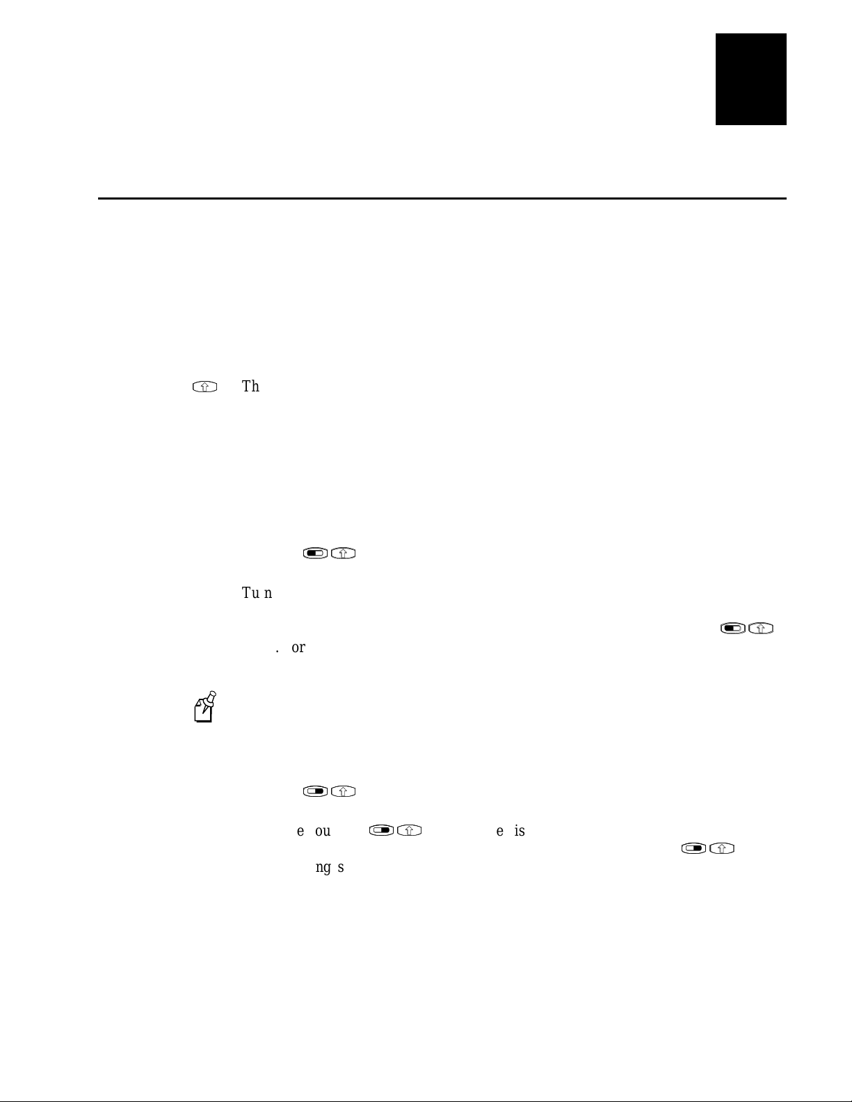
To access the TRAKKER Antares 2400 Menu System
•
Press
L
T
(57-key keypad),
L
L
X
X
(39-key
L
T
keypad), or scan this bar code:
Menu System
*..-.*
*..-.*
The Main Menu appears, displaying four menu options.
Configuration Menu
bar code symbologies, network and communications
parameters, serial port parameters, and the terminal’s
operating characteristics. In the Symbologies Menu,
active symbologies are noted with an asterisk (*).
Diagnostics Menu
hardware, software, or system diagnostics to help
analyze and fix problems. You can also view battery
and system information. For help, see Chapter 4,
“Running Diagnostics” in the 2400 Family system
manual.
Choose this menu to configure
Choose this menu to run
MAIN MENU
Configuration Menu
Diagnostics Menu
System Menu
About TRAKKER 2400
_` Select item
[Enter] Next screen
[F1] Help
[Esc] Exit
243XU050.eps
2-4
Page 45

nugget
MAIN MENU
Configuration Menu
Diagnostics Menu
System Menu
About TRAKKER 2400
SYSTEM MENU
File Manager
Load Default Values
Set Time and Date
Store Configuration
Upgrade Firmware
Clone Unit
DIAGNOSTICS MENU
Software Diagnosticss
Hardware Diagnostics
System Diagnostics
SOFTWARE DIAGNOSTICS
Error Logger
Application Events
Task Status
Clear Task Profiles
Font Test
Keypad Table
HARDWARE DIAGNOSTICS
Hardware Config
Battery/PIC Status
Display Test
Keypad Test
Main Board Menu
Radio Test
Scanner Test
SYSTEM DIAGNOSTICS
Subsystem Versions
Access Point
App Efficiency
Serial Port Test
Malloc Info Menu
Code Verify
CONFIGURATION MENU
Symbologies Menu
Symbology IDs Menu
Communications Menu
Terminal Menu
CONFIGURATION MENU
Symbologies Menu
Symbology IDs Menu
Communications Menu
Terminal Menu
TERMINAL MENU
Append Time
Beeper
Display
Keypad
Power Management
Preamble/Postamble
RAM Drive
Reader Command Menu
Scanner
SYMBOLOGIES MENU
*Code 39
Codabar
Code 93
*Code 128
2of5 / I 2of5
MSI
Plessey
*UPC / EAN
COMMUNICATIONS MENU
Primary Network
Advanced Network
Radio
Serial Port [COM1]
CONFIGURATION MENU
Symbologies Menu
Symbology IDs Menu
Communications Menu
Terminal Menu
243XU059.eps
CONFIGURATION MENU
Symbologies Menu
Symbology IDs Menu
Communications Menu
Terminal Menu
SYMBOLOGY IDs MENU
All Symbology IDs
Code 39
Code 128
Codabar
Code 93
Code 11
I 2of5
MSI Plessey
UPC A UPC E
EAN 8 EAN 13
S 2of5 2 Bar St/Sp
S 2of5 3 Bar St/Sp
System Menu Choose this menu to manage files, load the default configuration, set
the time and date, store the terminal’s configuration in flash memory, and upgrade the
firmware.
About TRAKKER 2400 Choose this option to see the part number, firmware version,
radio, and RF protocol (UDP Plus or TCP/IP) that is loaded on the terminal. You may
need this information if you are working a problem with an Intermec representative.
The TRAKKER Antares 2400 Menu System at a Glance
39
Configuring the Terminal
2
2-5
Page 46

Trakker Antares 243X Hand-Held Terminal User’s Manual
Accessing Online Help
The TRAKKER Antares 2400 Menu System provides online help for the menus and
commands.
To access a help screen
•
Press
to access a help screen.
G
G
To exit a help screen
E
•
Press
to exit the help screen.
E
Selecting Menus and Commands
A menu consists of a list of secondary menu items or commands. From the Main Menu,
U
you can press
For example, from the Main Menu, press
D
or
to select a menu, and then press
U
D
nugget
D
D
V
D
D
V
39
V
.
V
to display the System Menu:
MAIN MENU
Configuration Menu
Diagnostics Menu
System Menu
About TRAKKER 2400
_` Select item
[Enter] Next screen
[F1] Help
[Esc] Exit
243XU050.eps
SYSTEM MENU
File Manager
Load Default Values
Set Time and Date
Store Configuration
Upgrade Firmware
Clone Unit
_` Select item
[Enter] Next screen
[F1] Help
[Esc] Exit
243XU051.eps
Filling In Fields
Screens contain fields into which you can enter data. In the TRAKKER Antares 2400
U
Menu System, this data configures the terminal. You can press
on a screen and then enter data.
There are two types of fields: toggle fields and entry fields .
A
B
In a toggle field, press
•
In an entry field, type a value into the field. To edit the data in an entry field, use the
•
A
B
B
, or
N
keys. You can also use the Delete (DEL) and Insert (INS) keys to edit
N
A
,
A
,
B
, or
S
to view the options for that field.
S
an entry field.
D
or
to choose a field
U
D
2-6
Page 47

nugget
PRIMARY NETWORK
Activate:
Disabled
Host IP Addr:
0.0.0.0
Terminal IP Address:
0.0.0.0
243XU062.eps
OK CANCEL
READER COMMAND MENU
[Space] to enable or
disable a command
[X] Abort Program
[X] Backlight
[X] Backspace
[X] Change Config
[X] Clear
[X] Default Config
[X] Delete File
[X] Enter Accum
[X] Exit Accum
[X] List Files
243XU053.eps
OK
more
CANCEL
[X] Multi-Read
[X] Receive File
[X] Rename File
[X] Reset
[X] Run Program
[X] Scanner On
[X] Scanner Off
[X] Test & Service
[X] Transmit File
_
39
Configuring the Terminal
2
For example, the Primary Network screen has toggle and entry fields. The Activate field
is a toggle field. Press
B
to toggle between Disabled and 802.11 DS or OpenAir. The
B
Host IP Address and Terminal IP Address fields are entry fields. You type a value into
the field for each IP address.
Marking Check Boxes
Screens may contain check boxes. Check boxes are used when you can select more than
one option at a time. To mark or clear check boxes, press
to choose the Backspace check box and press
S
to clear the check box. The
S
Backspace command is now disabled.
S
. For example, press
S
U
U
or
D
2-7
D
Page 48

Trakker Antares 243X Hand-Held Terminal User’s Manual
PREAMBLE / POSTAMBLE
Preamble:
abc
Postamble:
\x0D\x0A
243XU057.eps
OK CANCEL
Entering ASCII Control Characters
You can include ASCII control characters in a postamble or preamble by using the
TRAKKER Antares 2400 Menu System. For a definition of the postamble or preamble,
see Chapter 6, “Configuration Command Reference,” in the 2400 Family system
manual.
You can configure the postamble or preamble to be characters from the full or extended
ASCII character sets. For example, the Field Exit code (Ü) for 5250 terminal emulation
is an extended ASCII character that is often configured as the postamble.
For help using the 5250 Field Exit code, see the appropriate TE manual.
Note:
To enter ASCII characters for a preamble or postamble
1. Decide which ASCII control character you want to set for the preamble or
postamble. Look up the control character in the “Full ASCII Table” in Appendix B
of the 2400 Family system manual and find the two-digit hexadecimal number. For
example, ETX in the Full ASCII Table is the hexadecimal value 03.
nugget
39
To enter an extended ASCII character,
look up the two-digit hexadecimal number
for the character in the “Trakker Antares
Terminal Font Set” in Appendix C of the
2400 Family system manual. For example,
Ü (the 5250 Field Exit code) has the
hexadecimal value 9A.
2. Use the TRAKKER Antares 2400 Menu
System to configure a preamble or
postamble. From the Main Menu, choose
Configuration Menu.
3. From the Configuration Menu, choose Terminal Menu.
4. From the Terminal Menu, choose Preamble/Postamble.
5. Move the cursor to the field for the preamble or postam ble.
2-8
Page 49

nugget
6. Type the control character, extended ASCII character, or escape character sequence
in the preamble or postamble field.
To type a control character or extended ASCII character in the preamble or
•
postamble field, use this syntax:
\x
hh
where hh is the two-digit hexadecimal number for the control character or
extended ASCII character. For example, to enter ETX as a preamble, type:
\x03
To enter Ü (the 5250 Field Exit code) as the postamble, type:
\x9A
To type an escape character (backslash) in the preamble or postamble field, you
•
must type two backslashes. The application ignores the first backslash (\)
character and saves the next characters. For example:
Enter These
Characters Preamble/Postamble Saved
39
Configuring the Terminal
2
\\ \
\\k \k
\ no data
7. Press
V
or choose OK to save your changes and exit the screen.
V
For help exiting the menu system, see the next two sections, “Exiting Screens and
Saving Changes” and “Exiting the Menu System.”
Exiting Screens and Saving Changes
When you exit a screen, you can save or discard your changes:
Task Description
To exit a screen and save the
changes
To exit a screen and discard
the changes
Choose OK and press
cursor positioned anywhere except on the Cancel button.
Choose Cancel and press
the cursor in any field.
. You can also press
V
V
. You can also press
V
V
V
V
with the
with
E
E
2-9
Page 50

Trakker Antares 243X Hand-Held Terminal User’s Manual
Save new
configuration
(in RAM)?
243XU052.eps
YES NO
CANCEL
Store configuration
changes in flash
memory?
(used when rebooting
the terminal)
243XU054.eps
YES NO
CANCEL
Exiting the Menu System
nugget
39
1. Press
E
until you exit the TRAKKER Antares 2400 Menu System. If you have
E
made any changes to the current configuration, the next screen prompts you to save
the configuration parameters that are currently enabled on the terminal to RAM.
2. Choose Yes and press
V
to save your changes in RAM and update the current
V
configuration on the terminal. The Main Menu appears.
Choose No and press
V
to exit without changing the configuration. The Main
V
Menu appears.
Choose Cancel and press
V
to return to the previous menu or screen.
V
2-10
3. From the Main Menu press
E
. If you have made any changes, the next screen
E
prompts you to store the changes in flash memory.
You can also save the current configuration in flash memory by choosing the
Note:
Store Configuration command from the System Menu. For help, see “Saving
Configuration Changes in Flash Memory” in Chapter 2 of the 2400 Family system
manual.
Page 51

nugget
Exiting
TRAKKER Antares 2400
Menu System
243XU055.eps
OK CANCEL
39
Configuring the Terminal
2
4. Choose Yes and press
saves the current configuration as the active configuration. The Exiting TRAKKER
Antares 2400 Menu System screen appears.
Choose No and press
changes until you boot or reset the terminal. The Exiting TRAKKER Antares 2400
Menu System screen appears.
Choose Cancel and press
5. Choose OK and press
V
to save your changes in flash memory. The terminal
V
V
to exit without saving. The terminal continues to use your
V
V
to return to the Main Menu.
V
V
to exit the TRAKKER Antares 2400 Menu System.
V
Configuring the Terminal With the Clone Application
Choose Cancel and press
After you exit the menu system, the terminal will resume the application you were
running when you started the menu system.
The clone application uses
applications from one 243X (server terminal) to another (client terminal). The server
and client terminals must have the same
hardware configuration.
•
version of firmware.
•
version of the clone application.
•
The clone application copies all configuration parameters, except for terminal IP
address, from the server terminal to the client terminal. You must configure the terminal
IP address separately. The clone application also removes all existing files on the client
terminal’s C drive, and replaces them with the files on the server terminal’s C drive.
V
to return to the Main Menu.
V
XMODEM-1K
protocol to copy configuration parameters and
2-11
Page 52

Trakker Antares 243X Hand-Held Terminal User’s Manual
For more information about upgrading firmware, see Chapter 2 in the 2400 Family
system manual. For more information about downloading applications, see “How to
Download and Run Applications” in Chapter 3 of the 2400 Family system manual.
To clone configuration parameters and applications
1. Make sure the server terminal’s configuration is saved in flash memory by scanning
this bar code:
Save Configuration in Flash Memory
*.+1*
*.+1*
2. Load all applications and files to clone on the server terminal’s C drive.
3. Run the clone application on the server unit.
a. From the Main Menu, select System Menu, and then select Clone Unit.
b. Select Server.
4. Connect COM1 on the server terminal to COM1 on the client terminal using the
cloning cable (Part No. 216-909-001) (sold and ordered separately).
nugget
39
The cloning process automatically begins once you connect the terminals. The
client terminal lists the app lic at ion s when clon ing is complete.
5. On the server terminal, press
by connecting it to the server terminal.
E
to exit. You can also configure another terminal
E
Configuring Drives and Memory on the Terminal
The 243X come with a 750K flash drive (C), 512K RAM reserved for applications, and
an additional 2MB extended flash memory. You can customize the terminal to your
needs by configuring
up to 256K of the 512K RAM as a RAM drive.
•
the additional 2MB flash memory to either store double-byte fonts or to use as a
•
2MB drive.
Configuring the RAM Drive
The 243X has a total of 512K RAM for the application execution space. You can
configure up to 256K of the total 512K application execution space as a RAM drive. If
the RAM drive is configured, your application execution space is reduced by the
amount of the RAM drive.
2-12
Page 53

nugget
For example, if your application size is 64K and drive E is configured as a 256K RAM
drive, you are using 320K of the 512K application execution space. The application
uses the remaining 192K of RAM as a Malloc/free dynamic memory pool.
By default, the RAM drive is not configured and the memory is available for
applications. You can configure the size of the RAM drive (E) and use drive E to
temporarily store data and files (up to 128 files).
After you disable or configure the RAM drive, you must save the configuration in flash
memory and boot the terminal for the change to take effect. For help, see “Saving
Configuration Changes in Flash Memory” in Chapter 2 of the 2400 Family system
manual.
When you boot or reset the terminal, all files on the RAM drive are destroyed.
Note:
For help configuring the RAM drive, see “RAM Drive Size” in Chapter 6 of the 2400
Family system manual.
39
Configuring the Terminal
2
Configuring Flash Memory
You can use the 2MB extended flash memory either to store double-byte fonts or to use
as a 2MB drive. By default, the 2MB of flash memory is configured to store a doublebyte font set (up to 2MB maximum).
If you are not using double-byte fonts, you can configure the 2MB flash memory as a
storage drive (D). If you configure the flash memory as drive D, use this drive to store
large lookup tables and data files (up to 128 files).
You can only configure the 2MB flash memory as a drive or to store fonts. You
Note:
cannot use the space for both. If you configure drive D, you cannot store a font in flash
memory.
For help configuring flash memory, see “Flash Memory Configuration” in Chapter 6 of
the 2400 Family system manual. For help loading double-byte fonts, see “Loading
Double-Byte Fonts” in Chapter 2 of the 2400 Family system manual.
2-13
Page 54

Blank page
Page 55

3
Operating the Terminal in a Network
Page 56

Blank page
Page 57

nugget
This chapter describes how to install and configure the 243X in a serial or RF network.
It also explains how the 243X fits into a particular network and how to use serial or
network communications.
39
Operating the Terminal in a Network
How the Terminals Fit Into Your Network
The 2430 and 2435 are versatile hand-held terminals that you can easily add to your
network or distributed data collection sy stem .
The terminals have a serial port to transmit data to and receive data from a host
computer or PC through RS-232 serial communications. You can use the 2430 and the
2435 as end devices in your wired network. You can also use the 2435 as an end device
in the RF network.
243X in a Wired Network
3
Mainframe
Ethernet
243X hardwired to PC
File server
Terminals
PC
243XU028.eps
3-3
Page 58

Trakker Antares 243X Hand-Held Terminal User’s Manual
Ethernet
Access point
TCP/IP
Direct Connect
UDP Plus
Access point
2435s
2435s
243XU026.eps
Host
DCS 30X
UDP Plus Network In a UDP Plus RF network, the 2435 communicates with a host
computer through the DCS 30X. The DCS 30X translates UDP Plus packets on the RF
network into TCP/IP packets on the wired network and vice versa. The access point acts
as a bridge to allow communications between the wired network and the RF network.
TCP/IP Direct Connect Network In a TCP/IP network, the 2435 communicates with a
host computer directly using TCP/IP for the RF protocol. The access point acts as a
bridge to allow communications between the wired network and the RF network.
2435s in a UDP Plus Network or a TCP/IP Direct Connect Network
nugget
39
3-4
Page 59

21XX access point 21XX access point 21XX access point
Router
Ethernet
192.9.200.X
subnetwork
192.9.175.X
subnetwork
243XU024.eps
192.9.175.7
DCS 30X
2435s
192.9.175.10
192.9.175.11
192.9.175.12
2435s
192.9.200.5, 192.9.200.6
nugget
Multiple Subnetworks (UDP Plus) In a UDP Plus network, you can install the 2435
terminals, access points, and DCS 30X as shown in the next illustration. All the
terminals and access points in this illustration communicate with the DCS 30X at IP
address 192.9.175.7. If you are using access points, a terminal can roam across
subnetworks.
If you are using the 011X Access Points, a terminal can only communicate with access
points that are in the same subnetwork. In this illustration, if you substituted the 011X
Access Points for the 21XX access points, the terminal at IP address 192.9.200.5 could
not communicate with the DCS 30X on the 192.9.175.X subnetwork.
39
Operating the Terminal in a Network
3
2435s in Multiple Subnetworks (UDP Plus)
3-5
Page 60

Trakker Antares 243X Hand-Held Terminal User’s Manual
21XX access point21XX access point21XX access point
Router
Ethernet
Host
192.9.200.X
subnetwork
192.9.175.X
subnetwork
2435s
192.9.175.10
192.9.175.11
192.9.175.12
243XU022.eps
2435s
192.9.200.5, 192.9.200.6
192.9.175.7
Multiple Subnetworks (TCP/IP) In a TCP/IP network, you can install the 2435
terminals and access points as shown in the next illustration. All the terminals and
access points in this illustration communicate with the host at IP address 192.9.175.7. If
you are using 21XX access points, a terminal can roam across subnetworks.
If you are using the 011X Access Points, a terminal can only communicate with access
points that are in the same subnetwork. In this illustration, if you substituted the 011X
Access Points for the 21XX access points, the terminal at IP address 192.9.200.5 could
not communicate with the host on the 192.9.175.X subnetwork.
2435s in Multiple Subnetworks (TCP/IP)
nugget
39
3-6
Page 61

Access point
192.9.200.X
subnetwork
192.9.175.X
subnetwork
Ethernet
Router
243XU020.eps
192.9.175.1
2435s
192.9.175.9
192.9.175.10
192.9.175.11
192.9.200.5
DCS 30X
nugget
Communicating Across Subnetworks (UDP Plus) You can install the 2435 terminals
and access points in one subnetwork and install the DCS 30X or host in another
subnetwork. In this network, you must configure additional network parameters (default
router and subnet mask). The next illustration shows the DCS 30X in another
subnetwork from the terminals.
2435s Communicating Across Subnetworks (UDP Plus)
39
Operating the Terminal in a Network
3
Using Serial Communications on the Terminal
The 243X has a serial port to transfer data to and from another device, such as a printer,
modem, or PC, using serial communications. Before you can use serial
communications, you must perform these steps:
1. Connect the terminal to a serial device or network. For help, see “Connecting to a
Serial Device or Network” in Chapter 1.
2. Choose a communications protocol. For help, see the next section, “Choosing a
Communications Protocol.”
3. Configure the serial port parameters to allow the terminal to communicate with a
host computer or serial device in a wired network. For help configuring the
terminal, see Chapter 2.
3-7
Page 62

Trakker Antares 243X Hand-Held Terminal User’s Manual
Depending on the protocol you choose in Step 2, you must set some or all of the
serial port parameters to have the terminal communicate with a host computer or
serial device in a wired network. The values you set for the terminal’s serial port
parameters must match the values set for the host’s (or other device’s) serial port
parameters.
Choosing a Communications Protocol
After you connect the 243X to a host computer or other serial device, you are ready to
configure the serial port parameters on the two devices. The terminal uses a
communications protocol and
through the serial ports.
You can configure a different communications protocol for each COM port. The
terminal’s built-in file operations use
Communications protocols determine exactly how data is transmitted between the
terminal and the connected device. Each protocol has parameters you can set, such as
baud rate and parity. Both the terminal and the connected device must use the same
protocol and parameter settings to communicate properly. For help with protocols, see
the Data Communications Reference Manual (Part No. 044737).
XMODEM
nugget
YMODEM
or
XMODEM
39
to handle data communications
YMODEM
or
for file transfer.
Binary Protocol
Binary protocol has no protocol. Characters are sent and received without being altered.
The Data Link Escape character (DLE) is
characters are not stripped out of the incoming data stream. No protocol characters, such
as EOM or SOM, are added. Binary mode supports CTS/RTS flow control.
You can configure the following serial port parameters:
Baud rate
•
Data bits
•
Parity
•
Stop bits
•
Flow control
•
inserted before any character, and DLE
not
3-8
Page 63

nugget
39
Operating the Terminal in a Network
3
Configurable Protocol
Configurable protocol is based on Intermec’s Polling Mode D protocol except that you
have the option to change some of the serial port protocol parameters or remove specific
events from the protocol, such as poll or handshake.
You can configure the following serial port parameters:
Baud rate
•
Data bits
•
Parity
•
Stop bits
•
Flow control
•
EOM (End of Message)
•
Configuration commands via serial port
•
LRC
•
SOM (Start of Message)
•
Handshake (enabled or disabled)
•
Poll (Polling) (enabled or disabled)
•
Timeout Delay
•
Configurable protocol uses EOM to determine one of the following serial
communications modes.
Character mode When EOM is disabled, the terminal communicates in Character
mode processing each character. Character mode supports both XON/XOFF and
CTS/RTS flow control.
Frame mode When EOM is enabled, the terminal communicates in Frame mode.
When a terminal sends a packet, it adds a protocol character. When a terminal receives a
packet, it strips any protocol characters before it sends the information to the terminal
application. Frame mode supports both XON/XOFF and CTS/RTS flow control. In
Frame mode, you can also configure the following serial port parameters:
Configuration commands via serial port
•
Handshake
•
LRC
•
SOM
•
After you enable Handshake, you can define poll and timeout delay.
3-9
Page 64

Trakker Antares 243X Hand-Held Terminal User’s Manual
Master Polling Protocol
Master Polling Mode D protocol requires the terminal to ask the downline serial device
for data it may have (polling) and to request to send data to the serial device (selecting).
There is no automatic polling, so your application must poll periodically for data.
Before each transmit operation, the terminal issues the SEL sequence for the device
addressed and sends the data if an acknowledge is received. Before each receive
operation, the terminal issues a poll sequence and waits for data or the RES character
(no data is available to send).
You can configure the following serial port parameter:
Baud rate
•
Point-to-Point Protocol
Point-to-Point protocol is not directly supported on the terminals. However, you can
simulate this protocol by setting the protocol to Configurable and configuring these
parameters:
Baud rate
•
Data bits
•
nugget
39
Parity
•
Stop bits
•
Flow control
•
EOM (Set EOM1 to \x0D, which is <CR>, and set EOM2 to \x0A, which is <LF>)
•
LRC (Disable)
•
Handshake (Disable)
•
With this protocol, you cannot configure values for intercharacter delay, turnaround
delay, and timeout delay. This protocol supports CTS/RTS flow control only.
Polling Mode D Protocol
Polling Mode D protocol requires the host computer to ask the terminal for data it may
have (polling) and to request to send data to the terminal (selecting). This protocol uses
an RS-232 interface and implements the user interface through reader commands.
Polling Mode D also supports XON/XOFF and CTS/RTS flow control.
You can configure the following serial port parameters:
Baud rate
•
Flow control
•
3-10
Page 65

nugget
39
Operating the Terminal in a Network
Using RF Communications on the Terminal
Caution
Make sure all components with antennas are at least 30 cm (1 ft) apart when power is
applied. Failure to comply could result in equipment damage.
Conseil
Assurez-vous que la distance entre tous les éléments avec antennes soit d'au moins
30 centimètres (un pied) avant de faire la connexion avec l'alimentation électrique,
faute de quoi vous risquez d'endommager votre installation.
The 2435 has an internal antenna to transfer data using RF communications. Before you
can use RF communications, you must perform these steps:
1. Plan and prepare your RF network. For help, see the next section, “Planning the
Network Connection.”
2. (UDP Plus network only) Configure the DCS 30X. For help, see “Configuring the
DCS 30X” on page 3-12.
3
3. Configure the access points. For help, see “Configuring the Access Points” on page
3-12.
4. Configure the network parameters on each terminal in the network.
The set of network parameters you must configure depends on whether you install
the terminal on the same subnetwork as the DCS 30X or host (TCP/IP) or on a
different subnetwork. For help determining which network parameters you must
configure, see “About the Network Parameters” on page 3-14.
Planning the Network Connection
To use the 2435 in the RF network, you need these minimum requirements:
DCS 30X (UDP Plus network)
•
Access point
•
When you first consider purchasing a wireless data collection system, an Intermec
representative works with you to perform a site survey at your facility. The site survey
analyzes the range of radio frequency devices in your facility and determines the
placement of the access points. The site survey ensures that the coverage of each access
point overlaps to provide uninterrupted wireless access at any location within the
building. This manual assumes that a site survey is complete and the access points are
installed in your facility.
You must work with your network administrator to plan and assign the IP address for
each device in the RF network. You must assign and set the IP address for each access
point (RF) and each 2435. If you are using a UDP Plus network, you must also assign
an IP address to the DCS 30X.
3-11
Page 66

Trakker Antares 243X Hand-Held Terminal User’s Manual
Configuring the DCS 30X
The DCS 30X supports and manages communications with other devices in the UDP
Plus network. When you install and configure the DCS 30X, you identify the host
computers and 2435 terminals in your network. The terminals communicate using a
reliable RF protocol (UDP Plus) to the DCS 30X. The DCS 30X translates UDP Plus to
a reliable wired protocol (TCP/IP) and sends the data to the host. For more information,
see the user’s manual for the DCS 30X.
You can use a 2435 running TCP/IP and the DCS 30X in a pass-through network.
Note:
You establish a direct TCP/IP socket connection from the 2435 to the host through the
server.
To allow the 2435 to communicate with the DCS 30X, you must perform these tasks on
the server:
Define the host communications parameters, which includes the physical
•
connection (network adapter cards) to the host.
Configure the UDP Plus network.
•
Assign an IP address to each 2435. If your DCS 30X is operating as a DHCP
•
(Dynamic Host Configuration Protocol) server, you also can leave the default
terminal IP address as 0.0.0.0 to enable the 243X as a DHCP client. The 243X can
receive terminal IP addresses dynamically from the DHCP server. For help, see
“DHCP (Terminal)” in Chapter 6 of the 2400 Family system manual.
nugget
39
Enable all 2435 terminals.
•
Define the host environment parameters, which includes configuring for terminal
•
emulation or client/serv er appl ic at ions.
To use dcBrowser, you do not define the host environment parameters. You must
create an HTML application.
•
configure the dcBrowser gateway.
•
Configuring the Access Points
Access points act as bridges to provide communicat ions between the wire d network and
the RF (UDP Plus or TCP/IP) networks. After you configure the network, you can
collect data anywhere within range of the access points in the wireless network. When
you move out of range of one access point, the 2435 automatically searches for other
access points to continue the network connection.
3-12
Page 67

nugget
If you are out of range of all access points in the network, the data is stored in the
terminal’s radio buffer. The Network Connect status icon turns off. You can continue to
collect data until the radio buffer is full. When the buffe r is ful l, the appl ic ation d isp lay s
a communication timeout status. When you move back into range and network
communications are re-established, the data in the radio buffer is transmitted to the
access point and you can once again transmit data.
In a TCP/IP direct connect network with a terminal running a terminal emulation
application, the application may disconnect from the host if you remain out of
communications range too long or if the host sends “Keep Alive” messages while the
terminal is in Suspend mode. You may need to restart the application and log back into
the host to re-establish a terminal emulation session. In a UDP Plus network, the session
is maintained any time the terminal is out of range or in Suspend mode.
To communicate through the network, all RF terminals must contain the same type of
radio, either a WLI Forum 2.4 GHz OpenAir or an IEEE 802.11b radio.
Depending on the radio in the terminal, you must set certain parameters to the same
configuration on both the terminal and the access points.
39
Operating the Terminal in a Network
3
OpenAir Radio
To use OpenAir radios in your network, you must set the following parameters:
Domain
•
(Optional) Security Identification (ID)
•
These parameters must be set to the same values on the terminals and the access points.
Each access point is configured with a different channel/subchannel combination.
On the access points, the Domain parameter is called the LAN ID (Domain)
Note:
parameter.
802.11b Radio
To use 802.11b radios in your network, you must set the following parameters:
Network Name
•
(Optional) WEP Encryption
•
These parameters must be set to the same value on the terminals and the access points.
You can also set the Network Name parameter to “ANY” on the terminal, allowing the
terminal to communicate with any access point that has the same radio and is within
range. The Network Name parameter is case-sensitive. For more information about the
WEP Encryption parameter, see Chapter 6 in the 2400 Family system manual.
On the access points, the Network Name parameter is called the SSID (Network
Note:
Name) parameter.
3-13
Page 68

Trakker Antares 243X Hand-Held Terminal User’s Manual
About the Network Parameters
When you install the 2435 in a network, you must configure the network parameters
that control how the terminal communicates in the network.
The set of network parameters you must configure depends on whether you install the
terminal on the same subnetwork as the DCS 30X or host (TCP/IP) or on a different
subnetwork.
You must define the following network parameters:
Network Activate
•
(UDP Plus) Controller IP Address
•
(TCP/IP) Host IP Address
•
Terminal IP Address (Non-DHCP environment only)
•
Network Port
•
(DCS 30X or host on different subnetwork) Default Router
•
(DCS 30X or host on different subnetwork) Subnet Mask
•
nugget
39
For help understanding these parameters and their syntax, see Chapter 6 in the 2400
Family system manual. For more information about network connectivity and protocols,
see Chapter 2 in the 2400 Family system manual.
Monitoring Network Communications
After you configure the 2435 in the RF network, you can use the application on the
2435 to collect and transmit data through network communications. If the 2435 is
communicating with your host computer, it will connect to your host computer and
begin running the application that shipped on the terminal.
As you use the 2435 to collect data, the Network Connect icon helps you monitor
network communications between the 2435 and other devices in the RF network. To
learn how to use the Network Connect icon, see “Learning About the Status Icons” in
Chapter 1.
3-14
Page 69

4
Troubleshooting and Maintaining the Terminal
Page 70

Blank page
Page 71

nugget
This chapter lists problems you may encounter while using the terminal and provides
some possible solutions. It also describes how to boot or reset the terminal and clean
the scanner window and terminal screen.
39
How to Use This Chapter
If you have any problems using the 243X, use this table as a guide to find the problem
and solution in this chapter:
Problem See This Section to Find a Solution Page
Troubleshooting and Maintaining the Terminal
4
Screen is blank, terminal is locked
up, or message i s displayed.
Configuri ng the terminal “Problems While Con figuring the Terminal” 4-6
(2435 only) RF communications
error
Running applications on the
terminal
Serial port communications error “Problems Transmitting Data Through the
DCS 30X application error “Problems Transmitting Data Thro ugh the
Scanning labels “Problems Scanning Bar Code Labels” 4-15
Boot Menu appears or terminal is
locked up.
Terminal or application is locked
up.
“Problems While Operating the Terminal” 4-4
“Problems Communicating With RF
Network Devices”
“Problems While Running Applications” 4-13
Serial Port”
DCS 30X”
“Booting the Terminal” 4-17
“Troubleshooting a Locked Up Application” 4-18
4-11
4-14
4-14
Terminal is not responding to the
Reset Firmware command.
Scanner window or termina l
screen is dirty.
“Resetting the Terminal” 4-19
“Cleaning the Scanner Window and Terminal
Screen”
4-20
4-3
Page 72

Trakker Antares 243X Hand-Held Terminal User’s Manual
You can also use the error numbers and messages table and the terminal diagnostics to
help analyze and solve problems. For help, see Chapter 4, “Running Diagnostics,” in the
2400 Family system manual.
If you have problems with the TE 2000 terminal emulation applications, see the
appropriate TE manual.
If you send the terminal in for service, it is your responsibility to save the terminal data
and configuration. Intermec is only responsible for ensuring that the keypad and other
hardware features match the original configuration when repairing or replacing your
terminal.
Problems While Operating the Terminal
If you are operating the terminal and have trouble, check these possible problems and
solutions.
Problem Solution
nugget
39
You press
screen is blank and nothing happens.
The terminal is booting and you see a
message that POST failed.
The terminal displays the Boot Menu. The Boot Menu appears if you just upgraded the firmware on the
You are sending and receiving information
through the network, and the terminal appears
to be opera ting slowly.
F
to turn on the terminal and the
F
The battery pack may not be installed correctly. For help, see
“Installing the Battery Pack” in Chapter 1.
The battery pack may be discharged. Replace the battery pack with a
spare charged battery pack, or charge the battery pack and try again.
The screen displays the system that failed POST. Report the error
message to your supervisor.
E
Press
to boot the terminal. Your application appears on the screen. If the
terminal still will not boot, contact your local Intermec service
representative for help.
terminal and POST failed. Press
problem to your supervisor.
If the main battery was removed from the terminal for an extended
period of time, when you replace the main battery, the Boot Menu
appears. Press
For help with t he Boot Menu, see “Booting the Terminal” on page
4-17.
The terminal may be configured for the 5x6, 6x8, or 12x16 font type.
These font type values may cause the 243X to scroll, and therefore
operate, more slowly when it displays information on t he scre en.
Change the font type to a value other than 5x6, 6x8, or 12x16. For help,
see “Display Font Type” or “Display Spacing” in Chapter 6 of the 2400
Family system manual. If the terminal continues to operate slowly,
contact your local Intermec service representative for help.
to exit the error message. The Boot Menu appears. Press
E
to boot the terminal. Report the
to boot the terminal and continue working.
4-4
Page 73

nugget
Troubleshooting and Maintaining the Terminal
39
Problems While Operating the Terminal (continued)
Problem Solution
You cannot scan bar code labels. See “Problems Scanning Bar Code Labels” on page 4-15.
4
You are scanning bar code labels, and the
terminal appears to be operating slowly.
You scan a reader command, such as Change
Configuration, and nothing happens.
You scan a valid bar code label to enter data
for your application. The data decoded by the
terminal does not match the data encoded in
the bar code label.
The terminal may be configured for the 5x6, 6x8, or 12x16 font type.
These font type values may cause the 243X to scroll, and therefore
operate, more slowly when it displays bar code values on the screen.
Change the font type to a value other than 5x6, 6x8, or 12x16. For help,
see “Display Font Type” or “Display Spacing” in Chapter 6 of the 2400
Family system manual. If the terminal continues to operate slowly,
contact your local Intermec service representative for help.
The reader commands are disabled. Scan the Enable Override
command shown here to temporarily enable all of the reader
commands. You can also enable or disable reader commands with the
TRAKKER Antares 2400 Menu System. For help, see “Command
Processing” in Chapter 6 of the 2400 Family system manual. When you
are finished, remember to disable the override so that your data is not
interpreted as a command.
Enable Override
*$+DC3*
*$+DC3*
The terminal may have decoded the bar code label in a symbology
other than the label’s actual symbology. Try scanning the bar code
label again. Make sure you scan the entire label.
To operate the terminal quickly and efficiently, you should enable only
the bar code symbologies that you are going to scan. If you enable
multiple symbologies, the terminal may, on rare occasions, decode a
bar code according to the wrong symbology and produce erroneous
results.
You want to restore the terminal’s default
configuration so that you can reconfigure the
terminal.
Scan this bar code label:
Default Configuration
*.+*
*.+*
You can also use the TRAKKER Antares 2400 Menu System. For help,
see “Restoring the Terminal’s Default Configuration” in Chapter 2 of
the 2400 Family system manual.
After you load the default configuration, you may need to set the
primary network communications parameters to communicate with
other devic es in the net work.
4-5
Page 74

Trakker Antares 243X Hand-Held Terminal User’s Manual
Problems While Operating the Terminal (continued)
Problem Solution
nugget
39
The terminal appears to be locked up and you
cannot enter data.
Try these possible solutions:
•
(2435 only) Wait at least 10 seconds and try again. If the 2435 is
still connecting to the DCS 30X or host, it will ignore any input
from the keypad or scanner. Make sure the Network Connect icon is
on before continuing.
•
Scan a bar code label to see if the terminal responds.
•
Follow the instructions in “Troubleshooting a Locked Up
Application” on page 4-18.
•
If the terminal will not boot or reset, contact your local Intermec
service representative for help.
Problems While Configuring the Terminal
You can configure the terminal by using the TRAKKER Antares 2400 Menu System,
by scanning configuration commands, or by using the clone application. If you have
trouble configuring the terminal, check these possible problems and solutions.
Problem Solution
On the 2435, you configure the security ID
and the changes do not appear to be saved.
You can only set the security ID with the RF network enabled. The
Network Activate command must be set to the RF network befor e you
can save any changes to the Security ID command.
You are configuring SOM or EOM in the
Configuration Menu and cannot set two
characters.
You are scanning a configuration command to
set one of the serial port parameters and hear
three low beeps. For example, you are trying
to set EOM or SOM.
You scan or enter an option for the Scanner
Selection configuratio n command and you
hear three low beeps.
4-6
You may have a space in the SOM or EOM field. The space does not
show, but it is a valid character. To clear a space from the field, put the
L
cursor in the field and press
for SOM or EOM.
The order in which you scan serial port protocol configuration
commands is important. Configurable Serial Port (CSP) protocol uses
EOM to determine the serial communications mode. When EOM is
disabled, the terminal communicates in Character mode. When EOM is
enabled, the terminal communicates in Frame mode.
To use Frame mode, you need to set EOM first. Next, configure
Handshake, Configuration Commands Via Serial Port, LRC, SOM, and
then Poll. To use Character mode, you need to disable these same
parameters in reverse order.
For help, see “Using Serial Communications on the Terminal” in
Chapter 3.
You may have sc anned or e ntered a Scanner Selection command that
does not apply to the type of scanner that you have installed. Try
scanning or entering the Scanner Selection command again and select
an option for the type of module you have installed.
L
N
. Now set the two-character value
N
Page 75

nugget
Troubleshooting and Maintaining the Terminal
39
Problems While Configuring the Terminal (continued)
Problem Solution
4
You scan a configuration command, such as
Keypad Caps Lock, and nothing happens.
You scan a configuration command, such as
Keypad Caps Lock, and you hear three low
beeps.
One or more reader commands, such as Change Configuration, may be
disabled, so that you cannot change the configuration. Enable all of the
reader commands and try again.
The terminal may be waiting for another command to complete the
configurat ion change. If you started by scanning the Enter Accumulate
command, you must finish the comma nd by scanning the Exit
Accumulate command. For help, see Chapter 6, “Configuration
Command Reference,” in the 2400 Family system manual.
Scan Enable Override to temporarily enable all of the reader
commands. When you are finished, remember to disable the override so
that your data is not interpreted as a command.
Enable Override
*$+DC3*
*$+DC3*
If you are working in the TRAKKER Antares 2400 Menu System, you
cannot scan configurati on commands. Use the Configuration Menu to
change the terminal’s configuration, or exit the menu system to scan
configura t ion commands.
Check the command you are trying to scan. Make sure the command is
set correctly for the options and network communications you are using
with the terminal. For help, see Chapter 6, “Configuration Command
Reference,” in the 2400 Family system manual.
On the 2435, you scan a configuration
command to set one of these parameters and
hear three low beeps:
•
Controller IP Address (UDP Plus)
or Host IP Address (TCP/IP)
•
Terminal IP Address
•
Default Router
•
Network Acti vat e
If the Network Activate command is enabled (RF network enabled) and
you are configuring the 2435, these IP addresses must define a valid
network configuration. For example, an invalid network configuration
would be a controller (or host) IP address set to 0.0.0.0 with the
network ena bled.
To set these four parameters, follow these steps:
1. Disable the Network Activate (NA) configuration command.
2. Set the terminal IP address and the controller IP address or the host
IP address.
3. Set the default router address (if necessary).
4. Enable the Network Activate command.
You can change an IP address with the network enabled as long as it
still defines a valid network configuration.
4-7
Page 76

Trakker Antares 243X Hand-Held Terminal User’s Manual
Problems While Configuring the Terminal (continued)
Problem Solution
nugget
39
You are configuring the serial port and see
this error message when exiting the
Configuration Menu:
Serial port configuration
error.
SOM cannot equal EOM.
Configuration was not updated.
You are configuring the serial port and see
this error message when exiting the
Configuration Menu:
Serial port configuration
error. DLE, XON, XOFF are not
valid values for either SOM or
EOM.
Configuration was not updated.
You are configuring the serial port and see
this error message when exiting the
Configuration Menu:
Serial port configuration
error.
SOM cannot equal the same value that is set for EOM. You cannot set
SOM to any of these values: AFF (ACK), DLE, NEG (NAK), Poll,
RES (EOT), REQ (ENQ), SEL, XOFF, or XON. You need to change
the value of SOM. Choose Serial Port from the Communications Menu.
For help, see “Start of Message (SOM)” in Chapter 6, “Configuration
Command Reference,” in the 2400 Family system manual.
EOM or SOM cannot be set to any of these values: AFF (ACK), DLE,
NEG (NAK), Poll, RES (EOT), REQ (ENQ), SEL, XOFF, or XON.
You must change the value of EOM or SOM. Choose Serial Port from
the Communications Menu.
For help, see “End of Message (EOM)” or “Start of Message ( SOM)”
in Chapter 6, “Configura t ion Command Reference,” in the 2400 Family
system manual .
EOM can be one or two ASCII characters, but the value for the first
character cannot be the same as the value for the second character.
Also, EOM cannot be set to any of these values: AFF (ACK), DLE,
NEG (NAK), Poll, RES (EOT), REQ (ENQ), SEL, XOFF, or XON.
You must change the value of EOM #1 or #2. Choose Serial Port from
the Communications Menu.
EOM #1 cannot equal EOM #2.
Configuration was not updated.
You are configuring the serial port and see
this error message when exiting the
Configuration Menu:
Serial port configuration
error.
SOM is set. You must also set
EOM.
Configuration was not updated.
4-8
For help, see “End of Message (EOM)” in Chapter 6, “Configuration
Command Reference,” in the 2400 Family system manual.
You must co nfigure a val ue for EOM before you can se t SOM or
disable SOM. You need to change the value of SOM. Choose Serial
Port from the Communications Menu.
Configurable Serial Port (CSP) protocol uses EOM to determine the
serial communications mode. When EOM is disabled, the terminal
communicates in Character mode. When EOM is enabled, the terminal
communicates in Frame mode.
To use Frame mode, you need to set EOM first. Next, configure
Handshake, Configuration Commands Via Serial Port, LRC, SOM, and
then Poll. To use Character mode, you need to disable these same
parameters in reverse order. For help, see “Using Serial
Communications on the Terminal” in Chapter 3.
Page 77

nugget
Troubleshooting and Maintaining the Terminal
39
Problems While Configuring the Terminal (continued)
Problem Solution
4
You are configuring the serial port and see
this error message when exiting the
Configuration Menu:
PG command failed.
Configuration was not updated.
You see this error message when exiting the
Configuration Menu:
Commandname
command failed.
Remainder of configuration not
updated.
You are configuring a 243X with the clone
application and see an error message.
PG is the Handshake configuration command. You must change the
value of Handshake or set other serial port parameters. Choose Serial
Port from the Communications Menu.
The order in which you set serial port protocol configuration
commands is important. To use Frame mod e, you need to set EOM
first. Next, configure Handshake, LRC, SOM, and then Poll. To use
Character mode, you must disable these parameters in reverse order.
For help, see “Using Serial Communications on the Terminal” in
Chapter 3.
The two-character name (syntax) of the configuration command that
failed is listed on the first line of the error message.
Check the command listed in the message. To find the command, use
the “Configura t ion Commands by Syntax” table in Appendix A of the
2400 Family system manual. Make sure the command is set correctly
for the options and network communications you are using with the
terminal. For help, see Chapter 6, “Configuration Command
Reference,” in the 2400 Family system manual. For example, you may
see this message:
SS
command failed.
There may be a problem with the configuration due to a change made
with the Scanner Selection (SS) command.
The server terminal and the client terminal may not have the same
hardware or software configuration. Make sure that both termi nals have
the same hardware configuration, fi rmware vers i on, and clone
application version. For help, see “Configuring the Terminal With the
Clone Application” in Chapter 2.
On the 2435, you see this error message when
exiting the Configuration Menu:
Network configuration error.
Network is enabled. Terminal IP
address or Controller (Host) IP
address set to an invalid
address of 0.x.x.x or
127.x.x.x. Configuration was
not updated.
The RF network is enabled and there is a problem with the network
configuration. You must change the terminal IP address, the controller
IP address (host IP address for a TCP/IP network), or both. Choose
Primary Network from the Communications Menu.
The terminal IP address or the controller/host IP address is set to
0.x.x.x or 127.x.x.x. These are invalid addresses. Set a valid IP address
for the terminal and DCS 30X or host.
For help, see “Using RF Communications on the Terminal” in
Chapter 3. If you cannot fix the addressing problem, check with your
network administrator to get the IP address assigned to the terminal and
the controller or host.
4-9
Page 78

Trakker Antares 243X Hand-Held Terminal User’s Manual
Problems While Configuring the Terminal (continued)
Problem Solution
nugget
39
On the 2435, you see this error message when
exiting the Configuration Menu:
Network configuration error.
Network is enabled. Terminal IP
address and Default Router
address set to the same
address. Configuration was not
updated.
On the 2435, you see this error message when
exiting the Configuration Menu:
Network configuration error.
Network is enabled. Terminal IP
address or Controller (Host) IP
address set to the same
address. Configuration was not
updated.
The RF network is enabled and there is a problem with the network
configuration. You must change the terminal IP address, the default
router address, or both. Choose Primary Network or Advanced
Network from the Communications Menu.
The terminal IP address and the default router address are both set to
the same address. Set a valid IP address for the terminal and the default
router.
For help, see “Using RF Communications on the Terminal” in
Chapter 3. If you cannot fix the addressing problem, check with your
network administrator to get the IP addresses for each RF network
device.
The RF network is enabled and there is a problem with the network
configuration. You must change the terminal IP address, the controller
IP address (host IP address for a TCP/IP network), or both. Choose
Primary Network from the Communications Menu.
The terminal IP address and the controller/host IP address are both set
to the same address. Set a valid IP address for the terminal and
DCS 30X or host.
For help, see “Using RF Communications on the Terminal” in
Chapter 3. If you cannot fix the addressing problem, check with your
network administrator to get the IP address assigned to the terminal and
the DCS 30X or host.
On the 2435, you see this error message when
exiting the Configuration Menu:
Network configuration error.
Network is enabled. Default
Router address is not on the
terminal’s network.
Configuration was not updated.
4-10
The RF network is enabled and there is a problem with the network
configuration. You must change the default router address. Choose
Advanced Ne twork from the Communications Menu.
The terminal and DCS 30X (UDP Plus network) or host (TCP/IP
network) are on different networks, and the terminal is not on the same
network as the default router. When the terminal is on a different IP
subnetwork from the DCS 30X or host, you must set the Default Router
and Subnet Mask commands. Set a valid IP address for terminal,
DCS 30X or host, and default router.
For help, see “Using RF Communications on the Terminal” in
Chapter 3. If you cannot fix the addressing problem, check with your
network administrator to get the IP addresses for each network device.
Page 79

nugget
Troubleshooting and Maintaining the Terminal
39
Problems Communicating With RF Network Devices
If the 2435 is not communicating with other devices in the RF network, check these
possible problems.
Problem Solution
4
When you turn on the terminal after it was
suspended for 10-15 minutes or longer, the
terminal can no longer send or receive
messages over the network.
The Network Connect icon is off. The 2435 is
not communicating with the access point.
The host may have deactivated or lost your current terminal emulat ion
session. In a TCP/IP direct connect network, you need to turn off the
“Keep Alive” message (if possible) from the host so that the TCP
session is maintained while a terminal is suspe nde d.
Make sure the access point is turned on and operating. You may also be
using the terminal out of range of an access point. Try moving closer to
an access point to re-establish communications.
Make sure the Network Activate command is enabled . For help, see
“Network Acti va te” in Chapter 6 of the 2400 Family system manual.
Make sure the 2435 is configured correctly for your network. In an
OpenAir network, the domain and the security ID on the terminal must
match the values set for all access points the terminal may
communicate with. In an 802.11b network, the network name on the
terminal must match the values set for all access points the terminal
may communicate with. For help, see “Using RF Communications on
the Terminal” in Chapter 3.
In a TCP/IP direct connect network, you cannot scan or enter data when
the 2435 is not communicating with an access point or you may lose
your TCP session.
If you are within range of an access point, the Network Activate
command is enabled, and the Network Connect icon is still off, you
may have a defective radio card. For help, contact your local Intermec
service representative.
The Network Connect icon blinks on the
terminal screen.
In a UDP Plus network, the terminal is communicating with an access
point, but it is not connected to the DCS 30X. You may need to check
the 2435 configuration or make sure the DCS 30X is running and that
data collection is started.
The 2435 may be out of range of an access point or the access point
may have recently been turned off. Make sure the access point is still
turned on and the 2435 is with in range.
Each device in the network must have a valid IP address. The IP
addresses set on the terminal must match the addresses configured on
the DCS 30X or host. For help, see “Using RF Communications on the
Terminal” in Chapter 3.
4-11
Page 80

Trakker Antares 243X Hand-Held Terminal User’s Manual
nugget
Problems Communicating With RF Network Devices (continued)
Problem Solution
39
The Network Connect icon blinks on the
terminal screen and you see this message:
Unable to connect to
controller. Error 102.
Unable to establish connection
to host. Session ended.
The Network Connect icon is on, but you
cannot establish a terminal emulation session
with the host computer.
The Network Connect icon is on, but the host
computer is not receiving any data from the
2435.
The 2435 is connected to the access point but is trying to establish
communications with the DCS 30X and the host computer. Make sure
the terminal is correctly configured for your network. In a UDP Plus
network, make sure the DCS 30X is configured and data collection is
started. In a TCP/IP network, make sure the host computer is
configure d and running.
If the network is configured correctly, try shutting down and restarting
the DCS 30X to establish communications. You can also reset the
terminal. For help, see “Resetting the Terminal” on page 4-19.
There may be a problem with the host computer, a problem with the
connection between the DCS 30X and the host computer, or a problem
with the connection between the access point and the host (TCP/IP).
Check with your network administrator to make sure the host is
running and allowing users to login to the system.
In a UDP Plus network, there may be a problem with the connection
between the DCS 30X and the host computer. Check with your network
administrator or use the user’s manual for the DCS 30X to troubleshoot
any potential problems with the server.
In a TCP/IP network, there may be a problem with the connection
between the access point and the host computer. Check with your
network administrator or use your access point user’s manual to trouble
shoot any potential problems with the access point.
The 2435 is connected to the DCS 30X or
host compute r, and you move to a new site t o
collect data. The Network Connect icon was
on and now begins to blink or turns off.
You are sending and receiving information
through the network, and the terminal appears
to be opera ting slowly.
4-12
You may have gone out of range of an access point. Try moving closer
to an access point or to a different location to re-establish
communications. Once you are in range again, the Network Connect
icon will appear and remain on. Any data you collected while you were
out of range will be transmitted over the network.
The terminal may be configured for the 5x6, 6x8, or 12x16 font type.
These font type values may cause the 243X to scroll, and therefore
operate, more slowly when it displays information on t he scre en.
Change the font type to a value other than 5x6, 6x8, or 12x16. For help,
see “Display Font Type” or “Display Spacing” in Chapter 6 of the 2400
Family system manual. If the terminal continues to operate slowly,
contact your local Intermec service representative for help.
Page 81

nugget
Troubleshooting and Maintaining the Terminal
39
Problems While Running Applications
If you are running applications on the terminal and have trouble, check these possible
problems and solutions.
Problem Solution
4
There is not enough memory to load a
program.
You see this er ror message when trying to
load a program:
ERROR LOADING MODULE
LIBRARY NAME:
<
libraryname
FILE NAME:
<
filename
libraryname
where
library and files names of the progra m.
You see one of these error messages while
running a PSK or EZBuilder application:
SCREEN ERROR: 30
Code: 9
Hit any key To exit!
>
>
filename
and
are the
You need to free conventional me mory.
You need to free conventional me mory.
You must set the RAM Drive Size configuration command. For help,
see “RAM Drive Size” in Chapter 6, “Configuratio n Command
Reference,” in the 2400 Family system manual.
SCREEN ERROR: 31
Code: 3
Hit any key To exit!
You try to run a DOS application in the
TRAKKER Antares 2400 Menu System and
see this message:
Not a valid application.
A DOS command does not work. For a list of commands, see “Using ROM-DOS Commands” in
The terminal does not boot after you modified
the CONFIG.SYS file to configure a
ROM-DOS RAM drive.
You tried to run a DOS .EXE application from the TRAKKER Antares
2400 Menu System. You can only run .BIN applications in the menu
system. To run a DOS .EXE application, enter the filename at the DOS
prompt. For help, see “Running DOS Applications and Using ROMDOS Commands” in Appendix D of the 2400 Family system manual.
Appendix D of the 2400 Family system manual.
Correct the error in CONFIG.SYS and use the DOS software tools to
recreate drive A with the corrected CONFIG.SYS file.
4-13
Page 82

Trakker Antares 243X Hand-Held Terminal User’s Manual
nugget
39
Problems Transmitting Data Through the Serial Port
If you are having problems sending or receiving data through the serial port on the
terminal, check these possible problems:
Make sure the terminal is connected to the PC, host computer, or serial device
•
through COM1. For help, see “Connecting to a Serial Device or Network” in
Chapter 1.
Make sure you are using the appropriate cable to connect the terminal to the PC,
•
host, or serial device.
Make sure the terminal’s serial port parameters are config ured to m atch the ser ia l
•
port configuration on the host computer or serial device. For help, see “Using Serial
Communications on the Terminal” in Chapter 3.
Problems Transmitting Data Through the DCS 30X
If you have a problem while running the application on the terminal in a UDP Plus
network, check these possible communications problems.
Problem Solution
Transaction Buffer Full. The buffer holding transactions to be sent to the controller is full. Stop
collecting data with this terminal. Make sure the terminal is
communicating with the DCS 30X and let the terminal send all the
transactions in the buffer before you continue collecting data.
Sending Buffer Transactions. This is an information message to tell you that buffered transactio ns are
now being sen t to the DCS 30X. You can begi n collecting data again
once the message clears.
Transaction Aborted. The transaction just sent to the DCS 30X was not received. Try sending
the transaction again.
Transmit Error XX, press Enter. There is an error tr ans mitting data to the DC S 3 0X. XX represents the
status code error. Note the error code listed in the message and contact
your local Intermec service representative for help. Press
continue.
Receive Error XX, press Enter. There is an error receiving data from the DCS 30X. XX represents the
status code error. Note the error code listed in the message and contact
your local Intermec service representative for help. Press
continue.
Shutting down. The DCS 30X is shutting down. You may continue collecting data and
buffer the transactions in the terminal until the DCS 30X starts again or
stop collecting data with the terminal.
V
V
V
V
to
to
Controller Shutdown. The DCS 30X ha s shut down. You may continue collecting data and
buffer the transactions in the terminal until the DCS 30X starts again or
stop collecting data with the terminal.
4-14
Page 83

nugget
Troubleshooting and Maintaining the Terminal
39
Problems Scanning Bar Code Labels
If you cannot scan bar code labels or you are having problems with the scanner, check
these possible problems.
Problem Solution
4
The terminal is turned off. Make sure the terminal is turned on. Press
You cannot see a red beam of light from the
scanner when you press the scan button and
aim the scanner at a bar code label.
You have an input device attached to the
terminal and it cannot read any bar code
labels.
You may be too far away from the bar code label. Try moving closer to
the bar code label and scan it again.
You may be scanning the bar code lab el “straight on.” Try changing the
scanning angle.
Warning
Do not look directly into the window area or at a reflection of
the laser beam while the laser is scanning. Long-term exposure
to the laser beam can damage your vision.
Avertissement
Ne regardez pas directement la réflexion d’un rayon laser ou
dans la fenêtre du laser lorsque celui-ci est en opération. Si
vous regardez trop longtemps un rayon laser, cela peut
endommager votre vue.
You may not be using an input device that is supported by the 243X.
Make sure you are using one of the supported input devices listed in
Appendix A, “Specifications.”
Your 243X may not be configured for the input device connected to it.
You must configure the Scanner Selection command and select the
input device that is connected to the terminal. For help, see “Scanner
Selection” in Chapter 6, “Configurat io n Co mmand Reference ,” in t he
2400 Family system manual.
to turn on the terminal.
F
F
You try to scan a bar code label with an input
device and the integrated scanner on the
terminal turns on.
The input device connected to the terminal
does not appear to work well or read bar code
labels very quickly.
Your 243X may not be configured for the input device connected to it.
You must configure the Scanner Selection command and select the
input device that is connected to the terminal. If this command is not
defined for the appropriate input device, the scanner trigger on the
input device may activate the integrated scanner on the terminal. For
help, see “Scanner Selection” in Chapter 6, “Configuration Command
Reference,” in the 2400 Family system manual.
Make sure that the Scanner Selection command is set to the specific
tethered scanner you have attached. For help, see “Scanner Selection”
in Chapter 6, “Configura t ion Command Reference,” in the 2400 Family
system manual .
Check the bar code symbologies you have enabled on the terminal.
Enable only the symbologies that you are using.
4-15
Page 84

Trakker Antares 243X Hand-Held Terminal User’s Manual
Problems Scanning Bar Code Labels (continued)
Problem Solution
nugget
39
The integrated scanner does not read the bar
code labels quickly, or the scanning beam
seems to be faint or obscured.
When you release the Scan Button, the Good
Read LED does not turn off.
The scanner will not read the bar code label. Make sure you aim the scanner beam so it crosses the entire bar code
The scanner window may be dirty. Clean the window with a solution of
mild soap and water. Wipe dry. Do not allow abrasive material to touch
the window.
The Good Read LED remains on if you configure the terminal to use
edge trigge ring. If you configure the terminal for level triggering and
the Good Read LED remains on, there may be a problem with the LED.
Press the Scan Button again without scanning a bar code label. If the
LED is still on, contact your local Intermec service representative.
label in one pass.
The angle at which you are scanning the bar code label may not be
working well, or you may be scanning the label “straight on.” Try
scanning the bar code la bel again, but va ry the scanning angle.
The bar code label print quality may be poor or unreadable. To check
the quality of the bar code label, try scanning a bar code label that you
know scans. Compare the two bar code labels to see if the bar code
quality is too low. You may need to replace the label that you cannot
scan.
Make sure the bar code symbology you are scanning is enabled. Use
the TRAKKER Antares 2400 Menu System to check the symbologies.
On the Symbologies Menu, each symbology that is enabled has an
asterisk (*) next to the name of the symbology. If your bar code
symbology is disabled, enable it and then try scanning the bar code
label again.
You are scanning bar code labels, and the
terminal appears to be operating slowly.
4-16
Make sure that the application you are running on the terminal is
expecting input from a bar code. You may need to type this information
instead of scanning it.
The terminal may be configured for the 5x6, 6x8, or 12x16 font type.
These font type values may cause the 243X to scroll, and therefore
operate, more slowly when it displays bar code values on the screen.
Change the font type to a value other than 5x6, 6x8, or 12x16. For help,
see “Display Font Type” or “Display Spacing” in Chapter 6 of the 2400
Family system manual. If the terminal continues to operate slowly,
contact your local Intermec service representative for help.
Page 85

nugget
Booting the Terminal
You seldom need to boot or reset the terminal. When you boot the terminal, it runs
through power-on self test (POST) to test each major subsystem. The terminal uses the
configuration currently saved in flash memory. After the terminal is finished booting,
your application appears on the screen.
You can boot the terminal using these two methods:
39
Troubleshooting and Maintaining the Terminal
4
Configure the
•
Use the Boot Menu.
•
F
key to boot the terminal when you turn on the terminal.
F
Booting the Terminal on Resume
When you press
When you press
terminal configuration.
There are two ways to configure the
command:
Resume Execution Not Allowed Configures the terminal to boot and restart your
application each time you press
to restart your application every time you turn on the terminal.
Resume Execution Allowed Configures the terminal to resume exactly where it was
when you turned off the terminal. Use this option to resume working each time you turn
on the terminal.
You can configure the Resume Execution command by using the TRAKKER Antares
2400 Menu System or by scanning these bar code labels. For help, see Chapter 2,
“Configuring the Terminal,” or “Resume Execution” in Chapter 6 of the 2400 Family
system manual.
F
to turn off the terminal, it turns off and goes into Suspend mode.
F
F
to turn on the terminal, it resumes or boots depending on the
F
F
key using the Resume Execution configuration
F
F
to turn on the terminal. Use this option if you want
F
Resume Execution Not Allowed Resume Execution Allowed
*$+ER0* *$+ER1*
*$+ER0* *$+ER1*
4-17
Page 86

Trakker Antares 243X Hand-Held Terminal User’s Manual
Using the Boot Menu
To access the Boot menu, you can
upgrade the firmware. For help, see “Upgrading the Firmware” in Chapter 2 of the
•
2400 Family system manual.
reset the terminal. For help, see “Resetting the Terminal” on page 4-19.
•
remove the main battery and wait longer than 15 minutes to install a charged main
•
battery. This procedure also performs a destructive reset, which can have
unpredictable results.
The Boot Menu contains these commands:
nugget
39
Boot System Press
to boot the terminal. Once
the terminal is finished booting, your application
appears on the screen.
Run Loader Press
to load the terminal
firmware. To upgrade or load the firm w are, use the
Firmware Upgrade option in the TRAKKER
Antares 2400 Menu System. For help, see Chapter 2
in the 2400 Family system manual.
Power Down Press
to turn off the terminal.
When you turn on the terminal, the Boot Menu
screen appears again if POST passes.
Troubleshooting a Locked Up Application
If the terminal or application is locked up and the term ina l will not resp ond to any key
sequences, try the following steps in order:
1. Press
F
to turn off the terminal. Press
F
2. Use the TRAKKER Antares 2400 Menu System to reboot the terminal.
L
T
a. Press
L
T
or
Antares 2400 Menu System.
L
L
F
to turn on the terminal.
F
X
X
BOOT MENU
1 - Boot System
2 - Run Loader
3 - Power Down
POWER DOWN IN 60 SEC
to enter the TRAKKER
248XU104.eps
4-18
b. Choose System Menu and then Upgrade Firmware.
c. Choose OK, then YES, then press
d. Press
to boot the terminal.
E
. The Boot Menu appears.
E
Page 87

nugget
3. Scan the Reset Firmware label to restart the firmware and application.
Reset Firmware
*-.*
*-.*
If the terminal or application still will not respond, reset the terminal. For help, continue
with the next section.
Resetting the Terminal
If you performed the steps in “Troubleshooting a Locked Up Application” and the
terminal or application is locked up and the terminal will not respond to the Reset
Firmware command, follow the steps in this section to reset the terminal.
To reset the terminal
Scan the Boot Terminal label to reboot the terminal.
•
39
Troubleshooting and Maintaining the Terminal
4
Boot Terminal
*-.1*
*-.1*
If the terminal will not scan, you can perform a destructive reset. A destructive reset can
have unpredictable results.
1. If possible, press
2. Press and hold the
blinks once and the terminal turns off.
3. Press
4. Press
5. Set the time and date. For help using the TRAKKER Antares 2400 Menu System,
F
to turn on the terminal. The Boot Menu appears.
F
to boot the terminal. Once the terminal has finished booting, your
application appears.
see “Configuring the Term inal Wi th the Menu Sy stem ” in Chapter 2.
F
to turn off the terminal.
F
F
key for approximately 12 seconds. The Good Read LED
F
4-19
Page 88

Trakker Antares 243X Hand-Held Terminal User’s Manual
nugget
39
Cleaning the Scanner Window and Terminal Screen
The terminals are built for use in an industrial working environment. You may need to
perform these minor maintenance tasks to keep the terminal in good working order:
Clean the scanner window.
•
Clean the terminal screen.
•
Clean the scanner window and terminal screen as often as needed for the environment in
which you are using the terminal.
To clean the scanner window and terminal screen
1. Press
2. Use a solution of mild soap and water.
3. Dip a clean towel or rag in the soap and water solution and wring out the excess
4. Wipe dry.
Caution
There are no user-serviceable parts inside the terminal. Opening the unit will void the
warranty and may cause damage to the interna l componen ts.
Conseil
La terminal ne contient pas de pièces révisibles par l’utilisateur. Le fait d’ouvrir
l’unité annule la garantie et peut endommager les pièc es inte rn es.
F
to turn off the terminal.
F
solution. Wipe off the scanner window and terminal screen. Do not allow any
abrasive material to touch these sur fac es.
4-20
Page 89

A
Specifications
Page 90

Blank page
Page 91

nugget
This appendix lists the terminal’s physical and environmental specifications.
39
Physical and Environmental Specifications
You can use the tables in this section to find technical information about these features
and options:
Terminal Dimensions
•
Power Specifications
•
Electrical Specifications
•
Temperature and Environmental Specifications
•
Screen
•
Keypad Options
•
Application Options
•
Connectivity Options
•
Memory
•
Specifications
A
802.11b Radio Specifications
•
OpenAir Radio Specifications
•
Wired Data Communications
•
Bar Code Symbologies
•
Input Devices and Cables
•
Pin Assignments
•
Terminal Dimensions
Length: 25.4 cm (10 in)
Height: 4.6 cm (1.8 in) at grip
Width: 10.2 cm (4 in) at screen
Weight: 708.7 g (25 oz) with battery
Power Specifications
Operating: Rechargeable 1500 mAh battery pack
Backup: Rechargeable capacitor
Electrical Specifications
Models: 2430, 2435
Electrical rating:
S
7,4 to 12V; 750 mA
A-3
Page 92

Trakker Antares 243X Hand-Held Terminal User’s Manual
Temperature and Environmental Specifications
Operating the terminal: -20°C to 50°C -4°F to 122°F
Storing the terminal: -20°C to 50°C -4°F to 122°F
Charging the terminal: 0°C to 40°C 32°F to 104°F
Relative humidity: 0 to 90% non-condensing
Screen
•
CGA-compatible, backlit LCD
•
Configurable up to 21 lines by 31 columns
Keypad Options
•
(57-key) Alphanumeric keypad, available with programmable, international, 3270
TE, 5250 TE, or VT/ANSI TE overlays
•
(39-key) Alphanumeric keypad, available with programmable, international, 3270
TE, 5250 TE, or VT/ANSI TE overlays
Application Options
nugget
39
•
Programmable terminal
•
(2435) Data Collection Browser (dcBrowser)
•
(2435) TE 2000 terminal emulation
Connectivity Options
•
RS-232
•
(2435) TCP/IP with DHCP
•
(2435) UDP Plus with TFTP
Memory
•
4MB flash memory, 750K available for use (additional 2MB flash for double-byte
fonts or drive D)
•
1MB battery-backed RAM, 512K available for user
•
(2430) Extended memory option for an additional 2MB or 4MB SRAM storage
drive
A-4
Page 93

nugget
39
Specifications
802.11b Radio Specifications
Radio type Direct sequence, spread spectrum
Channels 11 (North America), 13 (Europe), 4 (France), 1 (Japan)
Data rate 11 Mbps (High), 5.5 Mbps (Medium), 2 Mbps (Standard),
1 Mbps (Low) with automatic fallback for increased range
Range (11 Mbps) 160 m (525 ft) open environment
50 m (165 ft) semi-open environment
24 m (80 ft) closed environment
Frequency band 2.4 to 2.5 GHz world-wide
OpenAir Radio Specifications
Radio type Frequency hopping, spread spectrum
Channels 15
Data rate 1.6 Mbps, 0.8 Mbps fallback
Range Up to 150 m (500 ft) indoors
Up to 300 m (1,000 ft) outdoors
Frequency band 2.4 to 2.5 GHz worldwide
A
Wired Data Communications
•
RS-232C serial port (COM1)
•
XMODEM/YMODEM
•
Protocols: Binary, Configurable Serial Protocol, Master Polling, and Polling
protocol for data transfer
Mode D
Bar Code Symbologies
•
Codabar
•
Code 11
•
Code 2 of 5
•
Code 39
•
Code 93
•
Code 128
The Code 11 symbology is only supported on 243X terminals configured for
Note:
•
Interleaved 2 of 5
•
MSI
•
PDF 417
•
Plessey
•
UPC/EAN
non-decoded scanning. The PDF 417 symbology is only supported on 243X terminals
configured for decoded scanning. For more information, see “Code 11” or “PDF 417” in
Chapter 6 of the 2400 Family system manual.
A-5
Page 94

Trakker Antares 243X Hand-Held Terminal User’s Manual
1-TXD
3-GND
RTS-4
5-CTS
Charge in
(12 VDC)-6
RXD-2
243XU036.eps
Input Devices and Cables
You must use an interface cable to connect an input device to the input device
connector. Use the following table to determine which non-decoded input device you
can attach to the 243X and which cable you need:
Non-Decoded Intermec Input Device Part No. Cable Part No.
1550C laser scanner 1550C0501 068424
1553E laser scanner 1550E0603 3-606031-00
1550C high visibility laser scanner 1550C0504 068424
1550C standard range laser scanner 1550C0500 068424
1551C standard range laser scanner 1551C0200 068424
1551E standard range laser scanner 1551E0600 Contact your Intermec
For a list of decoded input devices, contact your Intermec sales representative.
nugget
39
sales representative.
Note:
supports non-decoded input devices while the serial connector module supports decoded
input devices. Make sure that you select the appropriate input device for your connector
module. For help, see “Learning About the Connector Modules” in Chapter 1.
Intermec is constantly testing and developing new input devices. For an updated list of
Intermec-approved input devices for the 243X or for help determining which adapter
cable you need, see your Intermec sales representative.
Pin Assignments
You can use these pin assignments to make your own serial cables or troubleshoot
problems.
Pin Assignments for COM1
The following illustration shows the type of connector and the pin assignments for the
COM1 port.
The 243X has two connector module options. The standard connector module
A-6
Page 95

nugget
1 Not used
Not used-6
RTS-7
CTS-8
+5 V-9
2-RXD
3-TXD
4 Not used
5-GND
243XU040.eps
1-SSOS
ENABLE-6
GND-7
GND-8
+5 V-9
2-S DATA
3-SCAN LED
4-SPARE1
5-TRIGGER
243XU042.eps
39
Specifications
A
Pin Assignments for the Input Device Connectors
The following illustrations show the type of connectors and pin assignments for the
input device connectors on both the standard connector module and the serial connector
module.
Serial Connector Module Standard Connector
(Decoded Scanner Connector) (Module Non-Decoded Scanner Connector)
A-7
Page 96

Blank page
Page 97

I
Index
Page 98

Blank page
Page 99

nugget
39
Index
I
Symbols and Numbers
key, See Control key
C
C
key, See Shift key
W
W
key, See Function Left key
L
L
key, See Function Right key
R
R
key
F
F
configuring to boot the terminal, 4-17
turning the terminal on and off, 1-13
See also Suspend/Resume key
243X, See terminal
3270 and 5250 termina l em ula tion, See the TE 2000 5250
Terminal Emulation Programmer’s Guide or the TE
2000 3270 Terminal Emul ati on Pr ogrammer’s Guide
802.11b radio
access points, configuring, 3-13
specifications, A-5
Wi-Fi certified, 1-3
A
About TRAKKER 2400 screen, defined, 2-5
accent marks, entering, 1-15
accessories, described, 1-6
active configuration, 2-4
alphanumeric keypad, options, described, 1-11
Antares, See terminal
antenna, internal, 1-4
applications
options, described, A-4
TRAKKER Antares 2400 Menu System, using, 2-4 to 2-11
troubleshooting, 4-13
ASCII
control characters, post amble and preamble, entering, 2-8
extended characters, configuring, 2-8
audio signals, 1-4
list of, 1-20
volume, adjusting, 1-19
Automatic Shutoff command, managing battery power, 1-11
B
backlight, turning on and off, 1-17
backup power source
described, 1-4
specifications, A-3
bar code conventions, defined, xi
bar code labels
quiet zone, defined, 1-22
reader commands, troubleshooting, 4-5, 4-7
scanning
described, 1-21
troubleshooting, 4-15
bar code symbologies
list of, A-5
troubleshooting bad dec ode , 4- 5
See also the Trakker Antares 2400 Family System Manual
battery charger, terminal accessory, described, 1-6
battery charger, using, 1-9
battery pack
charging, 1-9
described, 1-4
determining when low, 1-8
installing, 1-9
managing power, 1-11
Battery status icon
described, 1-18
using, 1-8
beep
audio signals, list of, 1-20
three low beeps, troubleshooting, 4- 6, 4-7
volume, adjusting, 1-19
See also audio signals
Binary protocol, described, 3-8
blue keys, using, 1-13
booting the terminal
cold boot, 4-19
configuring the
POST failed, error message, 4-4
troubleshooting, 4-4
turning on the terminal, 1-13
warm boot, 4-19
box, shipping, contents of, 1-7
key, 4-17
F
F
C
cables
for input devices, A-6
terminal accessories, 1-6
capitalizing characters, 1-14
Caps Lock status icon, described, 1-19
cautions, defined, viii
CGA-compatible screen
described, 1-4
specifications, A-4
Character mode
EOM, described, 3-9
troubleshooting, 4-8
characters
capitalizing, 1-14
typing, 1-13
charging the battery pack, 1- 9
check boxes, marking, 2 - 7
cleaning
scanner window, 4-20
terminal screen, 4-20
clone application, configuring the terminal, 2-11
I-3
Page 100

Trakker Antares 243X Hand-Held Terminal User’s Manual
nugget
39
cloning cable
connecting to terminal, 2-12
terminal accessory, described, 1-6
cold boot, 4-19
COM ports, See serial port
COM1
described, 1-20
pin assignments, A-6
See also serial port
commands
conventions, def ine d, xii
selecting, 2-6
TRAKKER Antares 2400 Menu System, selecting, 2-6
See also the Trakker Antares 2400 Family System Manual
communications
protocols
Binary, 3-8
Configurable, 3-9
Master Polling, 3-10
Point-to-Point, 3-10
Polling Mode D, 3-10
serial, described, 3-8
RF specifications, A-5
status icons, using to monitor, 3-14
troubleshooting, 4-11, 4-14
Configurable protocol
Character mode, described, 3-9
described, 3-9
Frame mode, described, 3-9
configuration
active, 2-4
current, 2-4
default, 2-4
configuration commands
Automatic Shutoff, 1-11
Flash Memory Configuration, 2-13
RAM Drive Size, 2-12
troubleshooting, 4-6, 4-7
See also the Trakker Antares 2400 Family System Manual
Configuration Menu, defined, 2-4
Configuration Menu, problems while exiting, 4-6
configuring
booting the terminal on resume, 4-17
drives and memory, 2-12
flash memory, 2-13
network, overview, 3-11
protocol parameters
Binary, 3-8
Configurable, 3-9
Master Polling, 3-10
Point-to-Point, 3-10
Polling Mode D, 3-10
RAM drive, 2-12
summary of methods, 2-3
configuring (continued)
TRAKKER Antares 2400 Menu System, 2-4 to 2-11
troubleshooting, 4-6
connecting an input device, 1-24
connectivity options, described, A-4
connector modules, described, 1-23
connectors, pin assignments
COM1, A-6
input device, A-7
contrast, display, adjusting, 1-17
control characters, enterin g, 2-8
Control key, using, 1-14
conventions
bar code, defined, xi
commands, defined, xii
keypad, defined, x
screens and messages, defined, xi
warnings and cautions, defined, viii
copying configurations to another terminal, 2-11
current configuration, 2-4
customizing the terminal, 2-3
D
Data Collection Browser, See dcBrowser
dcBrowser, configuring, 3-12
DCS 30X, troubleshooting, 4-14
default configuration
described, 2-4
restoring, 4-5
Default Router command, determining when to
configure, 3-14
defining, terminal drives, 1-25
determining when the battery pack is low, 1-8
diacritical marks, entering, 1-15
Diagnostics Menu, defined, 2-4
dimensions of the terminal, A-3
docking connector, terminal accessory, described, 1-6
documentation
bar code conventions, defined, xi
command conventions, defined, xii
keypad conventions, defined, x
screen and message conventions, defined, xi
summary of each chapter, ix
warnings and cautions, defined, viii
double-byte fonts, configuring flash memory, 2-13
drive C, described, 1-26
drive D
configuring, 2-13
described, 1-26
drive E
configuring, 2-12
described, 1-26
drive G, described, 1-26
I-4
 Loading...