

Page 1

RS/6000 43P 7043 Models 150 and 260 Handbook
Volker Haug, Adnan Ikram, Heather Osbourne
International Technical Support Organization
http://www.redbooks.ibm.com
SG24-5144-00
Page 2

Page 3

SG24-5144-00
International Technical Support Organization
RS/6000 43P 7043 Models 150 and 260 Handbook
October 1998
Page 4

Take Note!
Before using this information and the products it supports, be sure to re ad the general infor mation in
Appendix B, “Special Notices” on page 247.
First Edition (October 1998 )
This edition applies to the RS/6000 43P 7043 Models 150 and 260 workstations and workgroup servers
for use with AIX Version 4.2.1, AIX Version 4.3.2, and subsequent r eleases o f t he operati ng syste m.
Comments may be addressed to:
IBM Corporation, Internation al Technical Support Organization
Dept. JN9B Building 045 Interna l Zip 2834
11400 Burnet Road
Austin, Texas 78758-3493
When you send information to IBM, you gra nt I BM a non-exclusive right to use or di strib ute t he
information in any way it belie ves appropr iate without incur ring any ob ligati on to you.
© Copyright International Business Machines Corpora tion 1998. All rights reserved
Note to U.S Government Users – Do cum entation r elated to r estric ted righ ts – Us e, duplication or dis closu re is
subject to restrictions set forth in GSA ADP Sc hedule Contra ct with IBM Co rp .
Page 5

Contents
Figures. . . . . . . . . . . . . . . . . . . . . . . . . . . . . . . . . . . . . . . . . . . . . . . . . . . .ix
Tables. . . . . . . . . . . . . . . . . . . . . . . . . . . . . . . . . . . . . . . . . . . . . . . . . . . . .xi
Preface . . . . . . . . . . . . . . . . . . . . . . . . . . . . . . . . . . . . . . . . . . . . . . . . . . .xiii
The Team That Wrote This Redbook. . . . . . . . . . . . . . . . . . . . . . . . . . . . . . . . xiii
Comments Welcome . . . . . . . . . . . . . . . . . . . . . . . . . . . . . . . . . . . . . . . . . . . . xv
Chapter 1. RS/6000 Introduction . . . . . . . . . . . . . . . . . . . . . . . . . . . . . . .1
1.1 RS/6000 Workstation Offerings . . . . . . . . . . . . . . . . . . . . . . . . . . . . . .1
1.2 RS/6000 43P 7043 Model 140 Overview . . . . . . . . . . . . . . . . . . . . . . .3
1.3 RS/6000 43P 7043 Model 150 Overview . . . . . . . . . . . . . . . . . . . . . . .3
1.3.1 RS/6000 43P 7043 Model 150 Key Attributes. . . . . . . . . . . . . . . .4
1.3.2 RS/6000 43P 7043 Model 150 Feature Summary. . . . . . . . . . . . .5
1.4 RS/6000 43P 7043 Model 260 Overview . . . . . . . . . . . . . . . . . . . . . . .6
1.4.1 RS/6000 43P 7043 Model 260 Key Attributes. . . . . . . . . . . . . . . .7
1.4.2 RS/6000 43P 7043 Model 260 Feature Summary. . . . . . . . . . . . .8
1.5 Performance Results . . . . . . . . . . . . . . . . . . . . . . . . . . . . . . . . . . . . . .9
1.5.1 SPEC95 Software Benchmark . . . . . . . . . . . . . . . . . . . . . . . . . .10
1.5.2 Performance Summary. . . . . . . . . . . . . . . . . . . . . . . . . . . . . . . .13
1.6 Industry Trends and Directions . . . . . . . . . . . . . . . . . . . . . . . . . . . . . .13
1.6.1 Microprocessor Future . . . . . . . . . . . . . . . . . . . . . . . . . . . . . . . .13
1.6.2 Universal Serial Bus. . . . . . . . . . . . . . . . . . . . . . . . . . . . . . . . . .14
1.6.3 The Accelerated Graphics Port. . . . . . . . . . . . . . . . . . . . . . . . . .14
1.6.4 IEEE 1394 . . . . . . . . . . . . . . . . . . . . . . . . . . . . . . . . . . . . . . . . .15
1.7 Workgroup Conferencing . . . . . . . . . . . . . . . . . . . . . . . . . . . . . . . . . .15
1.8 Year 2000 . . . . . . . . . . . . . . . . . . . . . . . . . . . . . . . . . . . . . . . . . . . . .18
Chapter 2. Hardware Overview . . . . . . . . . . . . . . . . . . . . . . . . . . . . . . .21
2.1 The RS/6000 Platform Architecture . . . . . . . . . . . . . . . . . . . . . . . . . .21
2.1.1 The RS/6000 Platform Architecture Introduction. . . . . . . . . . . . .21
2.1.2 Platform Topology . . . . . . . . . . . . . . . . . . . . . . . . . . . . . . . . . . .22
2.1.3 RS/6000 Platform Architecture Achievements. . . . . . . . . . . . . . .24
2.1.4 RPA Minimum System Requirements . . . . . . . . . . . . . . . . . . . . .25
2.2 The Hardware Design. . . . . . . . . . . . . . . . . . . . . . . . . . . . . . . . . . . . .26
2.2.1 Hardware Design for the RS/6000 43P 7043 Model 150. . . . . . .26
2.2.2 Hardware Design for the RS/6000 43P 7043 Model 260. . . . . . .29
2.3 Bus Architecture . . . . . . . . . . . . . . . . . . . . . . . . . . . . . . . . . . . . . . . . .32
2.3.1 The PCI Bus Architecture. . . . . . . . . . . . . . . . . . . . . . . . . . . . . .32
2.3.2 The ISA Bus Architecture . . . . . . . . . . . . . . . . . . . . . . . . . . . . . .33
2.3.3 The 60X and 6XX Bus . . . . . . . . . . . . . . . . . . . . . . . . . . . . . . . .34
© Copyright IBM Corp. 1998 iii
Page 6

2.3.4 The 6XX-MX I/O Bus . . . . . . . . . . . . . . . . . . . . . . . . . . . . . . . . .34
2.3.5 The X-Bus . . . . . . . . . . . . . . . . . . . . . . . . . . . . . . . . . . . . . . . . .35
2.4 The Processor Subsystem . . . . . . . . . . . . . . . . . . . . . . . . . . . . . . . . .35
2.4.1 The POWER3 Microprocessor . . . . . . . . . . . . . . . . . . . . . . . . . .35
2.4.2 The PowerPC 604e Microprocessor . . . . . . . . . . . . . . . . . . . . . .37
2.5 SMP Hardware Characteristics. . . . . . . . . . . . . . . . . . . . . . . . . . . . . .39
2.5.1 Memory Hierarchy . . . . . . . . . . . . . . . . . . . . . . . . . . . . . . . . . . .39
Chapter 3. Detailed Product Descriptions . . . . . . . . . . . . . . . . . . . . . .49
3.1 IBM RS/6000 43P 7043 Model 150 Product Description. . . . . . . . . . .49
3.1.1 Standard Features . . . . . . . . . . . . . . . . . . . . . . . . . . . . . . . . . . .50
3.1.2 Reliability, Availability, and Serviceability (RAS). . . . . . . . . . . . .56
3.1.3 Supported Optional Features . . . . . . . . . . . . . . . . . . . . . . . . . . .58
3.1.4 RS/6000 43P 7043 Model 150 Adapter Placement Guidelines . . 66
3.1.5 Service Package . . . . . . . . . . . . . . . . . . . . . . . . . . . . . . . . . . . .67
3.2 RS/6000 43P 7043 Model 260 Product Description . . . . . . . . . . . . . .68
3.2.1 Model 260 System Architecture . . . . . . . . . . . . . . . . . . . . . . . . .69
3.2.2 Standard Features . . . . . . . . . . . . . . . . . . . . . . . . . . . . . . . . . . .69
3.2.3 Reliability, Availability, and Serviceability (RAS). . . . . . . . . . . . .79
3.2.4 Supported Optional Features . . . . . . . . . . . . . . . . . . . . . . . . . . .82
3.2.5 RS/6000 43P 7043 Model 260 Adapter Placement Guidelines . . 92
3.2.6 Service Package . . . . . . . . . . . . . . . . . . . . . . . . . . . . . . . . . . . .94
3.3 IBM Multimedia Kit for RS/6000 . . . . . . . . . . . . . . . . . . . . . . . . . . . . .95
Chapter 4. Storage Architectures and Devices . . . . . . . . . . . . . . . . . .97
4.1 Storage Boot Devices. . . . . . . . . . . . . . . . . . . . . . . . . . . . . . . . . . . . .97
4.2 SCSI Overview. . . . . . . . . . . . . . . . . . . . . . . . . . . . . . . . . . . . . . . . . .97
4.2.1 SCSI-I . . . . . . . . . . . . . . . . . . . . . . . . . . . . . . . . . . . . . . . . . . . .97
4.2.2 SCSI-II . . . . . . . . . . . . . . . . . . . . . . . . . . . . . . . . . . . . . . . . . . . .98
4.2.3 SCSI-III . . . . . . . . . . . . . . . . . . . . . . . . . . . . . . . . . . . . . . . . . . .99
4.2.4 SCSI Terminology . . . . . . . . . . . . . . . . . . . . . . . . . . . . . . . . . .102
4.2.5 SCSI Repeaters . . . . . . . . . . . . . . . . . . . . . . . . . . . . . . . . . . . . 104
4.2.6 Summary of SCSI Specifications . . . . . . . . . . . . . . . . . . . . . . .105
4.3 SCSI Cabling . . . . . . . . . . . . . . . . . . . . . . . . . . . . . . . . . . . . . . . . . .105
4.3.1 General SCSI Cabling Considerations . . . . . . . . . . . . . . . . . . . 106
4.3.2 Cabling the PCI Single-Ended Ultra SCSI Adapter . . . . . . . . . . 109
4.3.3 Cabling the PCI Differential-Ended Ultra SCSI Adapter . . . . . . 113
4.4 Serial Storage Architecture Overview. . . . . . . . . . . . . . . . . . . . . . . . 118
4.5 Comparison between SCSI and SSA Architecture . . . . . . . . . . . . . .119
4.6 Internal SCSI Devices . . . . . . . . . . . . . . . . . . . . . . . . . . . . . . . . . . . 120
4.6.1 Disk Drives for the Model 150 and Model 260. . . . . . . . . . . . . . 120
4.6.2 Internal CD-ROM Drive. . . . . . . . . . . . . . . . . . . . . . . . . . . . . . .121
4.6.3 Internal Tape Drives. . . . . . . . . . . . . . . . . . . . . . . . . . . . . . . . .122
iv RS/6000 43P 7043 Models 150 and 260 Han dbo ok
Page 7

4.7 Internal SSA devices . . . . . . . . . . . . . . . . . . . . . . . . . . . . . . . . . . . . 123
4.8 PCI Storage Adapters . . . . . . . . . . . . . . . . . . . . . . . . . . . . . . . . . . .124
4.8.1 SCSI Adapters . . . . . . . . . . . . . . . . . . . . . . . . . . . . . . . . . . . . .124
4.8.2 SSA Adapter. . . . . . . . . . . . . . . . . . . . . . . . . . . . . . . . . . . . . . . 124
4.8.3 Storage Adapter Placement Guidelines for Model 150 and 260 126
4.9 External SCSI and SSA Storage Devices . . . . . . . . . . . . . . . . . . . . .126
Chapter 5. Adapters, Overview and Configuration. . . . . . . . . . . . . . .127
5.1 Communication Adapters . . . . . . . . . . . . . . . . . . . . . . . . . . . . . . . . .127
5.1.1 Token-Ring Adapter . . . . . . . . . . . . . . . . . . . . . . . . . . . . . . . . .127
5.1.2 Ethernet Adapters . . . . . . . . . . . . . . . . . . . . . . . . . . . . . . . . . . 128
5.1.3 ISDN Adapters . . . . . . . . . . . . . . . . . . . . . . . . . . . . . . . . . . . . .128
5.1.4 FDDI Adapters . . . . . . . . . . . . . . . . . . . . . . . . . . . . . . . . . . . . .129
5.1.5 ATM Adapters . . . . . . . . . . . . . . . . . . . . . . . . . . . . . . . . . . . . .131
5.1.6 Multiple Port Adapters . . . . . . . . . . . . . . . . . . . . . . . . . . . . . . .133
5.1.7 WAN Adapters . . . . . . . . . . . . . . . . . . . . . . . . . . . . . . . . . . . . .133
5.1.8 Miscellaneous Adapters . . . . . . . . . . . . . . . . . . . . . . . . . . . . . .134
5.2 Graphics Adapters . . . . . . . . . . . . . . . . . . . . . . . . . . . . . . . . . . . . . .135
5.2.1 POWER GXT120P (# 2838) . . . . . . . . . . . . . . . . . . . . . . . . . . .135
5.2.2 POWER GXT250P (# 2851) and POWER GXT255P (# 2852) . 136
5.2.3 POWER GXT550P (# 2845) . . . . . . . . . . . . . . . . . . . . . . . . . . .137
5.2.4 POWER GXT3000P Graphics Accelerator (# 2825) . . . . . . . . . 138
5.2.5 Graphics Adapter Feature Comparison . . . . . . . . . . . . . . . . . . .140
5.2.6 Graphics Adapters Attachment Cables . . . . . . . . . . . . . . . . . . .142
5.2.7 Multiple Adapter Support . . . . . . . . . . . . . . . . . . . . . . . . . . . . . 143
5.2.8 Accessing the Second Display . . . . . . . . . . . . . . . . . . . . . . . . .145
5.3 Adapter and Device Configuration on PCI-Based RS/6000 Systems 146
5.3.1 Device Types . . . . . . . . . . . . . . . . . . . . . . . . . . . . . . . . . . . . . .146
5.3.2 PCI Adapter Configuration . . . . . . . . . . . . . . . . . . . . . . . . . . . .150
5.4 Summary Chart of Adapters. . . . . . . . . . . . . . . . . . . . . . . . . . . . . . . 152
Chapter 6. Diagnostics and System Management Services . . . . . . . 155
6.1 Diagnostics Operating Considerations . . . . . . . . . . . . . . . . . . . . . . .155
6.2 Stand-Alone Diagnostics . . . . . . . . . . . . . . . . . . . . . . . . . . . . . . . . . 157
6.2.1 Booting the Stand-Alone Diagnostics CD-ROM . . . . . . . . . . . .157
6.2.2 Running Stand-Alone Diagnostics in Concurrent Mode . . . . . . . 158
6.3 On-line Diagnostics . . . . . . . . . . . . . . . . . . . . . . . . . . . . . . . . . . . . .158
6.3.1 Service Mode . . . . . . . . . . . . . . . . . . . . . . . . . . . . . . . . . . . . . .159
6.3.2 Concurrent Mode . . . . . . . . . . . . . . . . . . . . . . . . . . . . . . . . . . .160
6.3.3 Single-User Mode . . . . . . . . . . . . . . . . . . . . . . . . . . . . . . . . . . .161
6.4 Diagnostic Tasks and Service Aids. . . . . . . . . . . . . . . . . . . . . . . . . . 162
6.5 Understanding the Firmware . . . . . . . . . . . . . . . . . . . . . . . . . . . . . .166
6.5.1 General RS/6000 Boot Sequence. . . . . . . . . . . . . . . . . . . . . . .166
v
Page 8

6.5.2 Typical Boot Sequence for RS/6000 43P 7043 Model 150 . . . . 167
6.5.3 Typical Boot Sequence for RS/6000 43P 7043 Model 260 . . . . 168
6.6 Power-On Self-Test . . . . . . . . . . . . . . . . . . . . . . . . . . . . . . . . . . . . .170
6.6.1 Processor POST. . . . . . . . . . . . . . . . . . . . . . . . . . . . . . . . . . . .170
6.6.2 Memory DIMM and L2 Cache POST. . . . . . . . . . . . . . . . . . . . .170
6.6.3 Graphics Adapter POST. . . . . . . . . . . . . . . . . . . . . . . . . . . . . .171
6.6.4 Keyboard and Mouse Controller POST. . . . . . . . . . . . . . . . . . .172
6.6.5 SCSI Subsystem POST . . . . . . . . . . . . . . . . . . . . . . . . . . . . . .172
6.7 System Management Services (SMS) . . . . . . . . . . . . . . . . . . . . . . .172
6.7.1 SMS Start-Up. . . . . . . . . . . . . . . . . . . . . . . . . . . . . . . . . . . . . .173
6.7.2 SMS Graphical Main Menu. . . . . . . . . . . . . . . . . . . . . . . . . . . .174
6.7.3 SMS ASCII Main Menu. . . . . . . . . . . . . . . . . . . . . . . . . . . . . . . 180
6.7.4 SMS Firmware Update . . . . . . . . . . . . . . . . . . . . . . . . . . . . . . . 180
6.7.5 SMS Firmware Checkpoints . . . . . . . . . . . . . . . . . . . . . . . . . . .184
Chapter 7. Service Processor . . . . . . . . . . . . . . . . . . . . . . . . . . . . . . .185
7.1 Introduction to the Service Processor. . . . . . . . . . . . . . . . . . . . . . . .185
7.2 Customize and Access the Service Processor Menus . . . . . . . . . . . 186
7.2.1 How to Customize the Service Processor. . . . . . . . . . . . . . . . .186
7.2.2 How to Access Service Processor Menus Locally. . . . . . . . . . .187
7.2.3 How to Access Service Processor Menus Remotely. . . . . . . . . 187
7.3 Security Within the Service Processor . . . . . . . . . . . . . . . . . . . . . . .187
7.4 Service Processor Operational Phases . . . . . . . . . . . . . . . . . . . . . .188
7.4.1 Pre-Standby Phase . . . . . . . . . . . . . . . . . . . . . . . . . . . . . . . . . 189
7.4.2 Standby Phase. . . . . . . . . . . . . . . . . . . . . . . . . . . . . . . . . . . . .189
7.4.3 Bring-Up Phase . . . . . . . . . . . . . . . . . . . . . . . . . . . . . . . . . . . .190
7.4.4 Run-time Phase . . . . . . . . . . . . . . . . . . . . . . . . . . . . . . . . . . . .190
7.5 Main Menu . . . . . . . . . . . . . . . . . . . . . . . . . . . . . . . . . . . . . . . . . . . .191
7.5.1 Service Processor Setup Menu. . . . . . . . . . . . . . . . . . . . . . . . . 192
7.5.2 System Power Control Menu . . . . . . . . . . . . . . . . . . . . . . . . . .195
7.5.3 System Information Menu. . . . . . . . . . . . . . . . . . . . . . . . . . . . . 197
7.5.4 Language Selection Menu . . . . . . . . . . . . . . . . . . . . . . . . . . . .202
7.5.5 CALL-IN/CALL-OUT Setup Menu . . . . . . . . . . . . . . . . . . . . . . .202
7.5.6 Set System Name. . . . . . . . . . . . . . . . . . . . . . . . . . . . . . . . . . .209
7.6 General User Menu . . . . . . . . . . . . . . . . . . . . . . . . . . . . . . . . . . . . . 209
7.6.1 Power-On System . . . . . . . . . . . . . . . . . . . . . . . . . . . . . . . . . . 210
7.6.2 Read VPD Image from Last System Boot . . . . . . . . . . . . . . . . .210
7.6.3 Read Progress Indicators from Last System Boot. . . . . . . . . . . 210
7.6.4 Read Service Processor Error Logs . . . . . . . . . . . . . . . . . . . . .210
7.6.5 Read System POST Errors. . . . . . . . . . . . . . . . . . . . . . . . . . . .210
7.6.6 View System Environmental Conditions . . . . . . . . . . . . . . . . . .210
7.7 Service Processor Firmware Update . . . . . . . . . . . . . . . . . . . . . . . . 210
7.7.1 Updating Firmware from the Service Processor Menus. . . . . . . 211
vi RS/6000 43P 7043 Models 150 and 260 Han dbo ok
Page 9

7.7.2 Updating Firmware from the SMS Utilities . . . . . . . . . . . . . . . . 212
7.7.3 Updating Firmware from the Service Aids. . . . . . . . . . . . . . . . .212
7.7.4 Updating Firmware from AIX. . . . . . . . . . . . . . . . . . . . . . . . . . .212
7.8 Service Processor Checkpoints . . . . . . . . . . . . . . . . . . . . . . . . . . . .213
Chapter 8. Hints and Tips . . . . . . . . . . . . . . . . . . . . . . . . . . . . . . . . . .215
8.1 Electronic Key-Switch Function . . . . . . . . . . . . . . . . . . . . . . . . . . . .215
8.1.1
bootlist Command. . . . . . . . . . . . . . . . . . . . . . . . . . . . . . . . . .215
8.2 Entering Debug Mode. . . . . . . . . . . . . . . . . . . . . . . . . . . . . . . . . . . . 216
8.3 Backup and Cloning. . . . . . . . . . . . . . . . . . . . . . . . . . . . . . . . . . . . .216
8.3.1 The
bootinfo Command . . . . . . . . . . . . . . . . . . . . . . . . . . . . . . 216
8.3.2 Creating a System Backup . . . . . . . . . . . . . . . . . . . . . . . . . . . .217
8.3.3 Restoring Your System Backup . . . . . . . . . . . . . . . . . . . . . . . .217
8.3.4 Cloning. . . . . . . . . . . . . . . . . . . . . . . . . . . . . . . . . . . . . . . . . . . 218
8.3.5 Cloning on AIX Version 4.2 and 4.3 . . . . . . . . . . . . . . . . . . . . .223
8.4 Configuration Information. . . . . . . . . . . . . . . . . . . . . . . . . . . . . . . . .227
8.4.1 Information about the Processor. . . . . . . . . . . . . . . . . . . . . . . .234
8.4.2 Information about the Service Processor . . . . . . . . . . . . . . . . . 235
8.4.3 Information about the Environmental Sensors . . . . . . . . . . . . . 235
8.5 Network Boot Support . . . . . . . . . . . . . . . . . . . . . . . . . . . . . . . . . . .236
8.6 Using the Error Logging Facility . . . . . . . . . . . . . . . . . . . . . . . . . . . .237
8.7 Booting Problems. . . . . . . . . . . . . . . . . . . . . . . . . . . . . . . . . . . . . . .238
8.7.1 Booting from CD-ROM . . . . . . . . . . . . . . . . . . . . . . . . . . . . . . .238
8.7.2 System Hangs during AIX Boot Process. . . . . . . . . . . . . . . . . . 238
8.7.3 Recovering a System with No Bootable Media . . . . . . . . . . . . . 239
Appendix A. RS/6000 43P 7043 Model 140. . . . . . . . . . . . . . . . . . . . . . . 241
A.1 RS/6000 43P 7043 Model 140 Key Attributes . . . . . . . . . . . . . . . . . . . . 241
A.2 RS/6000 43P 7043 Model 140 Feature Summary . . . . . . . . . . . . . . . . . 242
A.3 Standard Features . . . . . . . . . . . . . . . . . . . . . . . . . . . . . . . . . . . . . . . . . 243
A.4 Supported Optional Features . . . . . . . . . . . . . . . . . . . . . . . . . . . . . . . . . 244
A.4.1 Storage Devices . . . . . . . . . . . . . . . . . . . . . . . . . . . . . . . . . . . . . . . 244
A.4.2 AIX Operating System . . . . . . . . . . . . . . . . . . . . . . . . . . . . . . . . . . 244
A.4.3 Year 2000 . . . . . . . . . . . . . . . . . . . . . . . . . . . . . . . . . . . . . . . . . . . . 245
Appendix B. Special Notices . . . . . . . . . . . . . . . . . . . . . . . . . . . . . . . . . . 247
Appendix C. Related Publications. . . . . . . . . . . . . . . . . . . . . . . . . . . . . . 251
C.1 International Technical Support Organization Publications . . . . . . . . . . 251
C.2 Redbooks on CD-ROMs. . . . . . . . . . . . . . . . . . . . . . . . . . . . . . . . . . . . . 251
C.3 Other Publications . . . . . . . . . . . . . . . . . . . . . . . . . . . . . . . . . . . . . . . . . 251
C.4 Web Resources . . . . . . . . . . . . . . . . . . . . . . . . . . . . . . . . . . . . . . . . . . . 252
vii
Page 10

How to Get ITSO Redb ook s . . . . . . . . . . . . . . . . . . . . . . . . . . . . . . . . .253
How IBM Employees Can Get ITSO Redbooks. . . . . . . . . . . . . . . . . . . . . . . 253
How Customers Can Get ITSO Redbooks. . . . . . . . . . . . . . . . . . . . . . . . . . . 254
IBM Redbook Order Form . . . . . . . . . . . . . . . . . . . . . . . . . . . . . . . . . . . . . . . 255
List of Abbreviations. . . . . . . . . . . . . . . . . . . . . . . . . . . . . . . . . . . . . . .257
Index . . . . . . . . . . . . . . . . . . . . . . . . . . . . . . . . . . . . . . . . . . . . . . . . . . . 259
ITSO Redbook Evaluation. . . . . . . . . . . . . . . . . . . . . . . . . . . . . . . . . . .267
viii RS/6000 43P 7043 Models 150 and 260 Ha ndb ook
Page 11

Figures
1. RS/6000 PCI Workstation/Server Family. . . . . . . . . . . . . . . . . . . . . . . . . . . 2
2. RS/6000 43P 7043 Model 150 (without Peripherals). . . . . . . . . . . . . . . . . . 4
3. RS/6000 43P 7043 Model 260 (without Peripherals). . . . . . . . . . . . . . . . . . 7
4. IEEE 1394 Connections. . . . . . . . . . . . . . . . . . . . . . . . . . . . . . . . . . . . . . . 15
5. RS/6000 Hardware for Workgroup Conferencing . . . . . . . . . . . . . . . . . . . 16
6. RS/6000 Models 150 and 260 are Year 2000 Ready . . . . . . . . . . . . . . . . 19
7. General Platform Topology . . . . . . . . . . . . . . . . . . . . . . . . . . . . . . . . . . . . 23
8. Planar Block Diagram of the RS/6000 Model 150 . . . . . . . . . . . . . . . . . . . 27
9. RS/6000 High Level System Block Diagram (Model 260) . . . . . . . . . . . . . 30
10. POWER3 Microprocessor Logical Block Diagram. . . . . . . . . . . . . . . . . . . 36
11. PowerPC 604e Microprocessor Logical Block Diagram . . . . . . . . . . . . . . 38
12. Memory Hierarchy . . . . . . . . . . . . . . . . . . . . . . . . . . . . . . . . . . . . . . . . . . . 40
13. The 4-Way Set Associative PowerPC/POWER2 L1 Data Cache . . . . . . . 41
14. The 128-Way Set Associative POWER3 L1 Data Cache . . . . . . . . . . . . . 42
15. Loading Instructions from Memory to a Floating-Point Register . . . . . . . . 43
16. SMP Cache Coherency Problem. . . . . . . . . . . . . . . . . . . . . . . . . . . . . . . . 44
17. False Sharing. . . . . . . . . . . . . . . . . . . . . . . . . . . . . . . . . . . . . . . . . . . . . . . 46
18. RS/6000 43P 7043 Model 150 (with Peripherals) . . . . . . . . . . . . . . . . . . . 49
19. RS/6000 43P 7043 Model 150 - System Board Locations. . . . . . . . . . . . . 51
20. RS/6000 43P 7043 Model 150 - Front View . . . . . . . . . . . . . . . . . . . . . . . 53
21. RS/6000 43P 7043 Model 150 - Rear View. . . . . . . . . . . . . . . . . . . . . . . . 54
22. RS/6000 43P 7043 Model 260 (with Peripherals, and Spaceball). . . . . . . 68
23. RS/6000 43P 7043 Model 260 - System Planar & I/O Board . . . . . . . . . . 71
24. RS/6000 43P 7043 Model 260 - Operator Panel. . . . . . . . . . . . . . . . . . . . 73
25. RS/6000 43P 7043 Model 260 - Front View . . . . . . . . . . . . . . . . . . . . . . . 75
26. RS/6000 43P 7043 Model 260 - Rear View. . . . . . . . . . . . . . . . . . . . . . . . 77
27. Slot Configuration on Memory Card. . . . . . . . . . . . . . . . . . . . . . . . . . . . . . 84
28. Model 150 with Multimedia Kit for RS/6000. . . . . . . . . . . . . . . . . . . . . . . . 95
29. SCSI III Standards Overview . . . . . . . . . . . . . . . . . . . . . . . . . . . . . . . . . . 100
30. SCSI Differential Example . . . . . . . . . . . . . . . . . . . . . . . . . . . . . . . . . . . . 104
31. Piggy Back Connectors . . . . . . . . . . . . . . . . . . . . . . . . . . . . . . . . . . . . . . 107
32. Differential External Narrow Bus . . . . . . . . . . . . . . . . . . . . . . . . . . . . . . . 116
33. Differential External Wide Bus . . . . . . . . . . . . . . . . . . . . . . . . . . . . . . . . . 117
34. Comparison between SCSI and SSA Subsystem . . . . . . . . . . . . . . . . . . 119
35. Devices Location Codes . . . . . . . . . . . . . . . . . . . . . . . . . . . . . . . . . . . . . 149
36. System Management Services - Main Menu. . . . . . . . . . . . . . . . . . . . . . 174
37. SMS Submenu Multiboot . . . . . . . . . . . . . . . . . . . . . . . . . . . . . . . . . . . . . 176
38. SMS Submenu Utilities . . . . . . . . . . . . . . . . . . . . . . . . . . . . . . . . . . . . . . 176
39. SMS Submenu - Firmware Passwords . . . . . . . . . . . . . . . . . . . . . . . . . . 178
40. Service Processor - Operational Phase Status Flow. . . . . . . . . . . . . . . . 188
© Copyright IBM Corp. 1998 ix
Page 12

41. RS/6000 43P 7043 Model 140. . . . . . . . . . . . . . . . . . . . . . . . . . . . . . . . . 242
x RS/6000 43P 7043 Models 150 and 260 Han dbook
Page 13

Tables
1. SPEC and LINPACK Performance.. . . . . . . . . . . . . . . . . . . . . . . . . . . . . . 13
2. Multiuser Performance. . . . . . . . . . . . . . . . . . . . . . . . . . . . . . . . . . . . . . . . 13
3. RPA Minimum System Requirements . . . . . . . . . . . . . . . . . . . . . . . . . . . . 25
4. PowerPC and Bus Specification . . . . . . . . . . . . . . . . . . . . . . . . . . . . . . . . 33
5. RS/6000 43P 7043 Model 150 - System Board Components Location. . . 52
6. Publications Shipped with the Model 150 . . . . . . . . . . . . . . . . . . . . . . . . . 55
7. Optional Memory for Model 150. . . . . . . . . . . . . . . . . . . . . . . . . . . . . . . . . 59
8. List of Orderable Monitors for Model 150. . . . . . . . . . . . . . . . . . . . . . . . . . 61
9. Adapter Placement Guidelines for Model 150 . . . . . . . . . . . . . . . . . . . . . . 66
10. RS/6000 43P 7043 Model 260 - System Planar & I/O Board Components 71
11. RS/6000 43P 7043 Model 260 - Operator Panel Components . . . . . . . . . 73
12. Storage Device Features. . . . . . . . . . . . . . . . . . . . . . . . . . . . . . . . . . . . . . 74
13. RS/6000 43P 7043 Model 260 - Rear View Components . . . . . . . . . . . . . 76
14. Publications Shipped with the Model 260 . . . . . . . . . . . . . . . . . . . . . . . . . 78
15. Available Publications for Model 260. . . . . . . . . . . . . . . . . . . . . . . . . . . . . 78
16. List of Orderable Monitors for Model 260. . . . . . . . . . . . . . . . . . . . . . . . . . 86
17. RS/6000 43P 7043 Model 260 - Adapter Placement Guidelines. . . . . . . . 93
18. Overview of SCSI-III Standards. . . . . . . . . . . . . . . . . . . . . . . . . . . . . . . . 101
19. Differential SCSI Modes. . . . . . . . . . . . . . . . . . . . . . . . . . . . . . . . . . . . . . 105
20. Single-Ended Ultra SCSI Adapter-to-First Device Cables. . . . . . . . . . . . 111
21. Device-to-Device Cables for Single-Ended Installations . . . . . . . . . . . . . 112
22. 16-Bit SCSI-II System-To-System Cable. . . . . . . . . . . . . . . . . . . . . . . . . 113
23. Terminators for Single-Ended Installations . . . . . . . . . . . . . . . . . . . . . . . 113
24. Differential-Ended Ultra SCSI Adapter-to-First Device Cables . . . . . . . . 114
25. Device-to-Device Cables for Differential-Ended Installations . . . . . . . . . 114
26. Terminator For Description-Ended Installations. . . . . . . . . . . . . . . . . . . . 116
27. Cabling for the PCI Differential Ultra SCSI Adapter. . . . . . . . . . . . . . . . . 117
28. Comparing SSA and SCSI. . . . . . . . . . . . . . . . . . . . . . . . . . . . . . . . . . . . 120
29. Internal Disk Drives for the Models 150 and 260. . . . . . . . . . . . . . . . . . . 121
30. Internal CD-ROM Drives for Models 150 and 260 . . . . . . . . . . . . . . . . . . 122
31. Internal Tape Drive for Model 150 . . . . . . . . . . . . . . . . . . . . . . . . . . . . . . 122
32. Internal Tape Drives for Model 260 . . . . . . . . . . . . . . . . . . . . . . . . . . . . . 123
33. Placement of PCI Storage Adapters into the Models 150 and 260 . . . . . 126
34. Graphics Adapters. . . . . . . . . . . . . . . . . . . . . . . . . . . . . . . . . . . . . . . . . . 140
35. Display Cable Feature Code Matrix. . . . . . . . . . . . . . . . . . . . . . . . . . . . . 142
36. Accessing a Second Display . . . . . . . . . . . . . . . . . . . . . . . . . . . . . . . . . . 145
37. Communication, Graphics, and Storage Adapters Summary . . . . . . . . . 152
38. Settings of Privileged and General Access Password. . . . . . . . . . . . . . . 188
39. Valid Serial Port Speeds . . . . . . . . . . . . . . . . . . . . . . . . . . . . . . . . . . . . . 206
40. Results of bootinfo -p. . . . . . . . . . . . . . . . . . . . . . . . . . . . . . . . . . . . . . . . 217
© Copyright IBM Corp. 1998 xi
Page 14

41. RS/6000 43P 7043 Model 140 Standard Configuration. . . . . . . . . . . . . . 243
42. RS/6000 43P 7043 Model 140 System Expansion . . . . . . . . . . . . . . . . . 243
xii RS/6000 43P 7043 Models 150 an d 26 0 Handb ook
Page 15

Preface
In an effort to provide customers with suitable products and solutions to help
their business grow, IBM announced in October of 1998 two new additions to
its RS/6000 workstation family. They are the RS/6000 43P 7043 Models 150
and 260. These products are an enhancement to the current line of entry
workstations that are ready for your mission-critical business applications.
This redbook gives a detailed understanding of the RS/6000 43P 7043
Models 150 and 260, providing all the technical information that is generally
requested by decision-makers during the pre-sale cycle. It is suitable as a
single-source of reference for both technical and non-technical professionals
and may therefore be useful to:
• Customers
• System administrators
• System engineers
• Customer engineers
The reader will find:
• An overview of the RS/6000 43P 7043 Models 150 and 260
• Discussion of hardware architecture
• Detailed product descr iption
• Information on storage and communication features
• Discussion on diagnostics and the service processor
Availability, reliability, and performance features are also described.
The introduction of the RS/6000 43P 7043 Models 150 and 260 will expand
the range of possible applications available on entry level workstations,
providing industry-leading performance at an affordable price.
The Team That Wrote This Redbook
This redbook was produced by a team of specialists from around the world
working at the International Technical Support Organization Austin Center.
Volker Haug is an Advisory I/T Specialist in Stuttgart, Germany. He has eight
years of experience in the RS/6000 and AIX field. He holds a degree in
Business Management from the Berufsakademie in Stuttgart. Volker has
© Copyright IBM Corp. 1998 xiii
Page 16

worked with UNIX systems for ten years. His areas of expertise include
RS/6000 workstations and workgroup servers, graphics, and AIX systems
management.
Adnan Ikram is a Product Specialist (AIX, RS/6000, Networking) in Karachi,
Pakistan. He has 3 and 1/2 years of experience in the RS/6000 and AIX field.
He holds a degree in Electronics (B.E.) from NED University of Engineering
and Technology, Karachi. Adnan has worked with UNIX systems for eight
years. His areas of expertise include technical marketing and support of the
RS/6000 product family, along with second level AIX support. He is also
involved in conducting AIX courses from Basic to Advanced levels at IBM’s
Education Center.
Heather Osbourne is an I/T Availability Specialist in Kingston, Jamaica. She
has six years of experience in the RS/6000 and AIX field. She holds a degree
in Computer Science and Physics (B.Sc.) from the University of the West
Indies. Her areas of expertise include AIX support, RS/6000 project services
implementation, networking and communications. She is also involved in
conducting AIX courses from Basic to Advanced levels at IBM’s Education
Center.
The project that produced this publication was coordinated by:
Scott Vetter International Tec hnical Support Organization, Austin
Center
We would also like to acknowledge the professionals who took the time to
provide invaluable advice and guidance during this project:
Aranda, Ricardo IBM Austin
Arroyo, Ron IBM Austin
Baldwin , Wayne IBM Austin
Bluethman, Robert IBM Austin
Bringol, Ron IBM Austin
Capps, Louis IBM Austin
Gschell, Verena IBM Munich
Goodman, Marvin IBM Austin
Henson, Tracey IBM Austin
James, Joey V. IBM Austin
Lehmann, Norma IBM Austin
Maule, Warren IBM Austin
xiv RS/6000 43P 7043 Mo dels 15 0 an d 260 Ha ndboo k
Page 17

Nguyen, Thoi IBM Austin
Patel, Raj IBM Austin
Peterson, Earl IBM Austin
Randall, Dave IBM Austin
Thurber, Steve IBM Austin
Walton, Scott IBM Austin
Comments Welcome
Your comments are important to us!
We want our redbooks to be as helpful as possible. Please send us your
comments about this or other redbooks in one of the following ways:
• Fax the evaluation form found in “ITSO Redbook Evaluation” on page 267
to the fax number shown on the form.
• Use the electronic evaluation form found on the Redbooks Web sites:
For Internet users
http://www.redbook s.ibm.com
For IBM Intranet users ht tp://w3.itso.ibm .com
• Send us a note at the following address:
redbook@us.ibm.com
xv
Page 18

xvi RS/6000 43P 7043 Mo dels 15 0 an d 260 Ha ndboo k
Page 19

Chapter 1. RS/6000 Introduction
Throughout 1997 IBM greatly simplified its RS/6000 product line by
eliminating redundant offerings and introducing new models that cover a
broad range of price and performance. In 1998, IBM continued this mission
by enhancing its server line with better performance and by offering bundled
solutions that target high availability markets and customers requiring
outstanding graphics performance.
The RS/6000 family is a scalable, compatible line of RISC UNIX workstations,
servers, and supercomputers that are reshaping the way companies operate.
This economical family of systems fulfills the computing requirements of
many small businesses, workgroups, and large enterprises. Powered by
IBM’s award winning AIX operating system, the RS/6000 has the advanced
technology and architecture needed to grow and adapt to your customer’s
ever changing workloads.
This publication covers the IBM RS/6000 43P 7043 Models 150 and 260
entry-level and technical workstations. The RS/6000 Models 150 and 260 are
workstations that are intended to enhance the RS/6000 family’s competitive
product line for the price-conscious UNIX market. The RS/6000 Models 150
and 260 are the systems targeted toward those customers looking for a
reliable, highly expandable system.
1.1 RS/6000 Workstation O fferings
Figure 1 on page 2 shows the current range of IBM RS/6000 PCI-based
workstation and server offerings. The workstations that are the topic of this
publication are shown in the shaded area.
The selected workstations share the following characteristics:
• Powered by the PowerPC 604e and POWER3
• Contain PCI adapter slots
• Offer more performance than the Model 140
© Copyright IBM Corp. 1998 1
Page 20
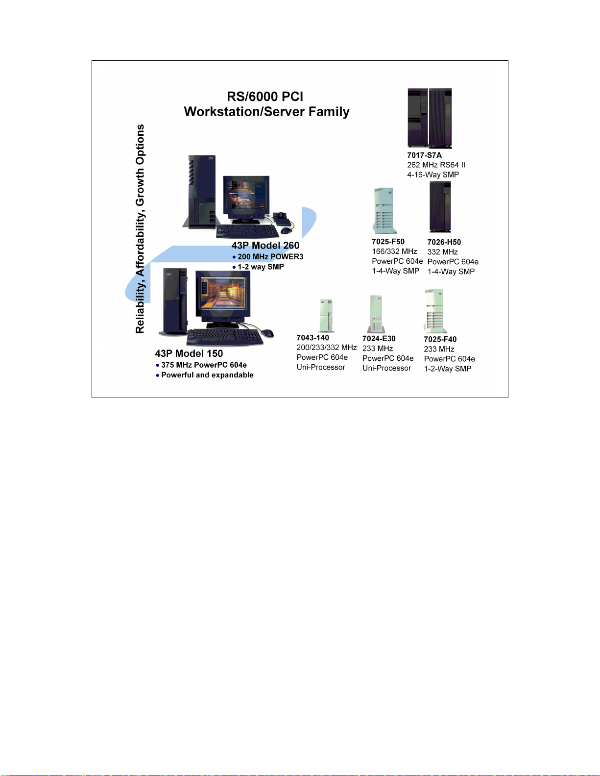
•
Figure 1. RS/6000 PCI Workstation/Server Family
The RS/6000 naming convention is patterned similarly to many of IBM’s
product lines. A product is represented as a four digit machine code followed
by a model number. A unique machine code is assigned to each series of
machines that fit together using similar designs or customer solutions. The
first character of the model number groups machines with a specific
enclosure together, and the remaining digits are typically used to indicate
performance within similar models. This convention is not without variations.
However, with this in mind, you can determine that the Models 140 and 150
are related, with the 150 being more powerful. This is also valid for the
Models 240 and 260.
2 RS/6000 43P 7043 Models 150 and 260 Han dbook
Page 21

The following sections provide an overview of the models that are the subject
of this publication.
1.2 RS/6000 43P 7043 Model 140 Overview
The main purpose of summarizing the IBM RS/6000 43P 7043 Model 140 in
this publication is to provide you with some background of this system. The
Model 140 is one of the most successful RS/6000 products that IBM has
announced in the workstation marketplace. Over 10,000 applications are
supported on this platform.
On October 6, 1997, IBM announced the PowerPC 604e 332 MHz
microprocessor option for the RS/6000 43P 7043 Model 140 as a new
member of the RS/6000 workstation and server family. The PowerPC 604e
332 MHz microprocessor is an easy upgrade from the current microprocessor
available with 200 MHz and 233 MHz processor options. The PowerPC 604e
332 MHz microprocessor option shows IBM’s commitment to improve the
value of its products and to protect existing investment.
More detailed information about the Model 140 can be found in Appendix A,
“RS/6000 43P 7043 Model 140” on page 241.
1.3 RS/6000 43P 7043 Model 150 Overview
The IBM RS/6000 43P 7043 Model 150 is an entry-level desktop RS/6000
workstation or workgroup server offered at an affordable price. The Model
150 provides a continuation of the successful line of entry workstations,
offering enhanced performance over the Model 140.
The Model 150 is a uni-processor system that provides enhanced
performance by utilizing a 375 MHz PowerPC 604e processor and an
enhanced memory controller. With this memory controller, the Model 150
uses SDRAM memory and an 83 MHz memory bus speed. The system
memory can be expanded up to 1 GB.
With Ethernet and Ultra SCSI controllers integrated on the planar, five PCI
slots and bays, the Model 150 is ready for expansion and growth.
The Model 150 is shown in Figure 2 on page 4.
RS/6000 Introduction 3
Page 22
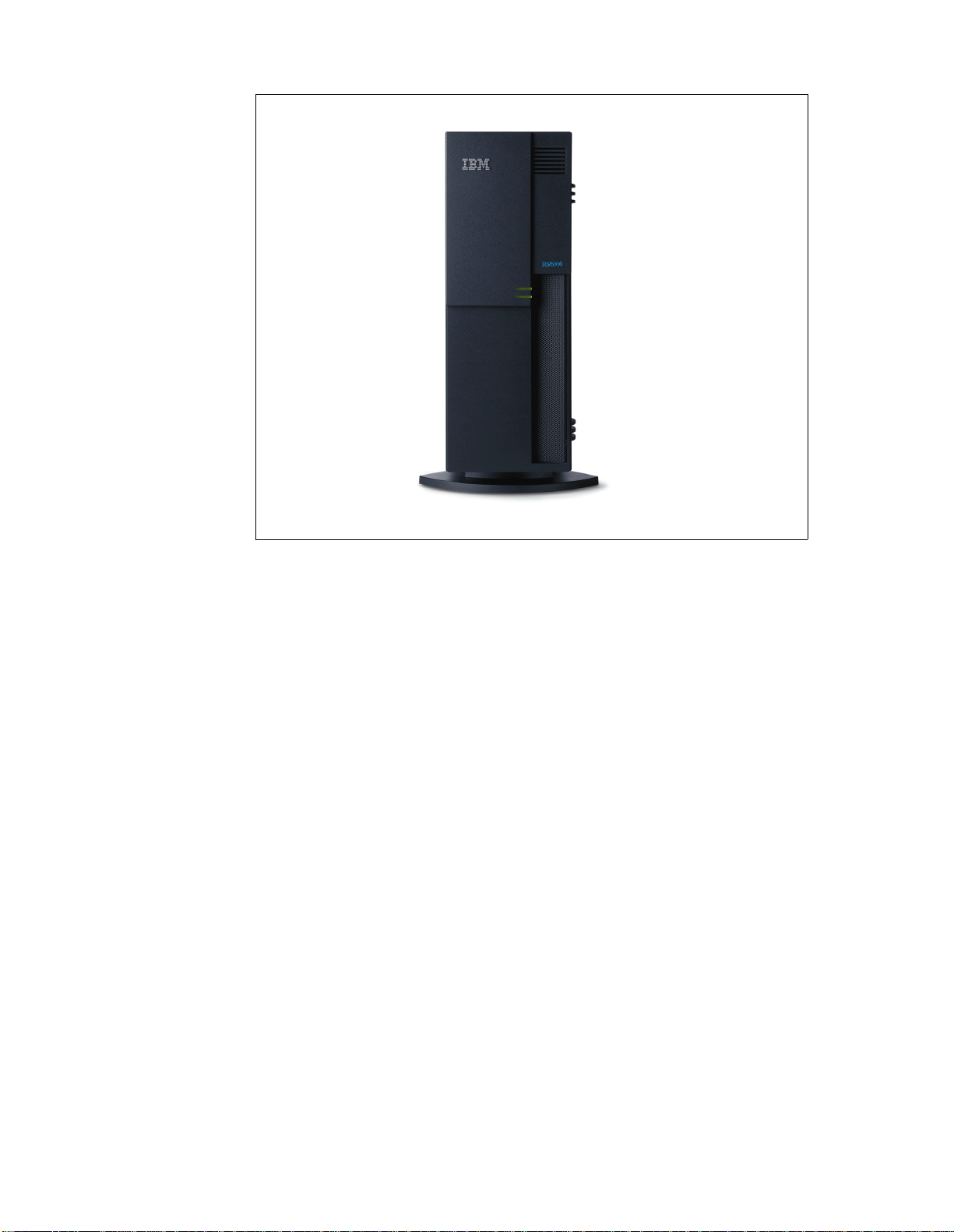
Figure 2. RS/6000 43P 7043 Model 150 (without Peripherals)
The Model 150 supports a variety of 2D and 3D graphics adapters including
the advanced 3D GXT3000P graphics adapter, providing excellent graphics
price performance. In addition, a robust set of disk drive and communications
features are available. The AIX Version 4.2.1 or 4.3.2 operating system for
one- to two-users is included in the cost of the Model 150 and can be
pre-installed, if desired.
1.3.1 RS/6000 43 P 7043 Model 15 0 Key Attribute s
The following is a list of the key attributes of the RS/6000 Model 150:
• Excellent graphics workstation that is ideal for running MCAD and other
technical applications.
• Powerful server that is ideal for running small-business and departmental
applications.
• Small footprint to fit into your department or work area.
4 RS/6000 43P 7043 Models 150 and 260 Han dbook
Page 23

• UItra SCSI and SSA storage options for improved data transfer
performance and high availability.
• Exceptional AIX operating system with reliability, availability, and
system-management features.
The Model 150 is designed to help customers run many mission-critical
business applications and networks twenty-four hours a day, seven days a
week.
1.3.2 RS/6000 43 P 7043 Model 15 0 Feature S ummary
The following is a summary of the key RS/6000 Model 150 features:
• Standard configuration:
• Microprocessor: 375 MHz PowerPC 604e processor
• Level 2 (L2) cache: 1 MB
• RAM (memory): 128 MB of ECC SDRAM memory
• Memory slots: Four
• Ports: One parallel and two serial
• Internal disk drive: 4.5 GB Ultra SCSI disk drive
• Disk/media bays: Five
• Expansion slots: 5 PCI slots
• PCI bus speed: 33 MHz
• Standard features:
• 32X max speed CD-ROM
• 1.44 MB 3.5-inch diskette drive
• Integrated 10/100 Mbps Ethernet controller (IEEE 802.3 compliant)
• Integrated Ultra SCSI controller
• Tablet port
• AIX operating system:
• Version 4.2.1 or Version 4.3.2 (1-2 user server license is standard)
RS/6000 Introduction 5
Page 24

• System expansion:
• RAM: Up to 1 GB
• Internal storage: 27.3 GB max
• External disk storage:
• Maximum external SCSI with expansion units: Up to 254.8 GB
• Maximum external SSA with expansion units: Up to 873.6 GB
• System dimensions:
• 6.5" H x 16.5" W x 18.1" D (165 mm x 420 mm x 460 mm)
• Weight: 14.5 kg (32 lbs)-Base configuration; 18.0 kg (40 lbs)-Full
featured configuration
• Operating environment
• Temperature: 16 to 32 degrees C (60 to 90 F)
• Relative Humidity: 8 to 80 (percent)
• Operating Voltage: 100 to 125 V AC or 200 to 245 V AC 50/60 Hz
(manual switch)
• Warranty:
• On-site for one year
1.4 RS/6000 43P 7043 Model 260 Overview
The RS/6000 43P 7043 Model 260 is a one-way or two-way symmetric
multiprocessing (SMP) system with the power to run complex commercial,
business and engineering applications.
The Model 260 provides enhanced performance over its predecessor, the
Model 240, by utilizing a 200 MHz POWER3 processor and an enhanced
memory controller. With this memory controller, the Model 260 uses ECC
SDRAM memory and a 100 MHz memory bus speed. The system memory
can be expanded up to 4 GB.
With Ethernet and Ultra SCSI controllers integrated on the planar, the Model
260 also contains five PCI slots and bays for expansion and growth capability.
Designed with reliability, availability, and serviceability (RAS) features
typically found in higher-priced systems, such as Error Checking and
Correcting (ECC) memory and an integrated service processor, the Model
260 can help keep your mission-critical business, technical applications, and
networks running twenty-four hours a day, seven days a week.
6 RS/6000 43P 7043 Models 150 and 260 Han dbook
Page 25
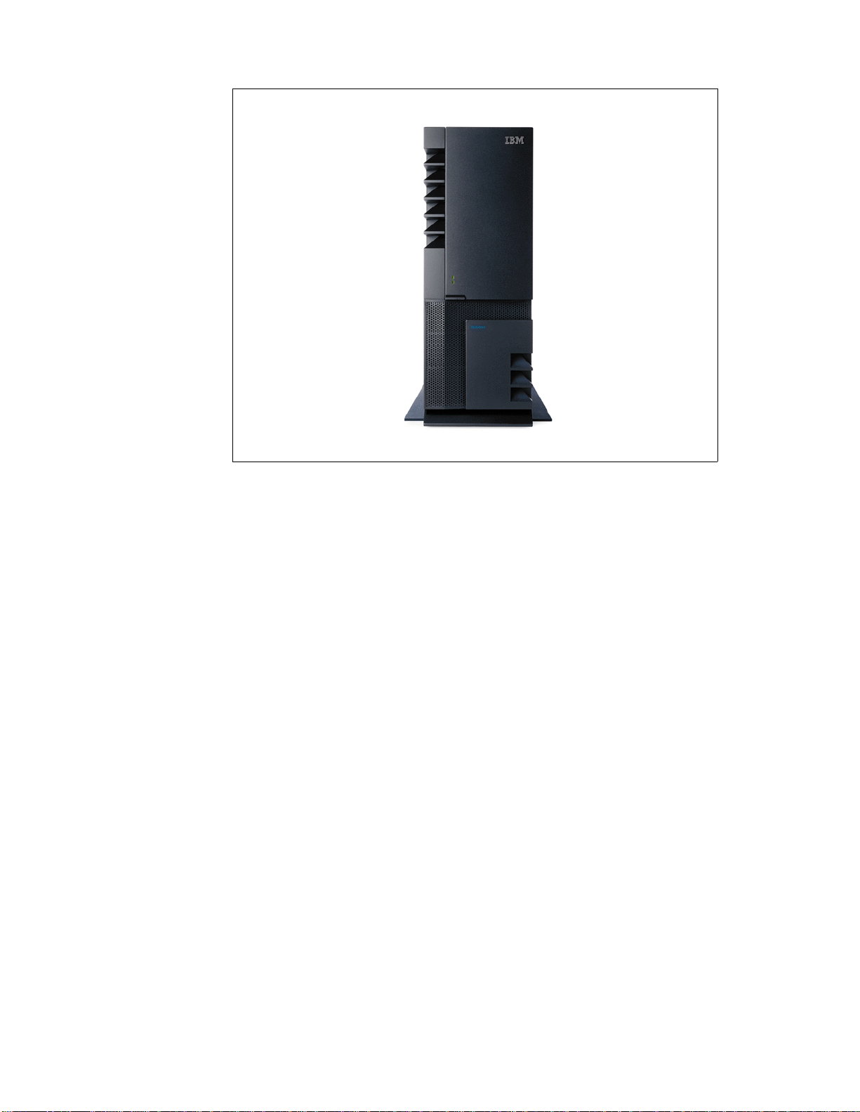
Figure 3. RS/6000 43P 7043 Model 260 (without Peripherals)
The Model 260 supports a variety of 2D and 3D graphics adapters including
the advanced 3D GXT3000P graphics adapter, offering excellent graphics
price and performance. In addition, a robust set of disk drive and
communications features are available. The AIX Version 4.2.1 or 4.3.2
operating system for one- to two-users is included in the cost of the Model
260 and can be available pre-installed, if desired.
The Model 260 is an ideal product for customers with a need for either an
entry or mid-range 2D or 3D graphics workstations or as an entry workgroup
server.
1.4.1 RS/6000 43 P 7043 Model 26 0 Key Attribute s
The following is a list of the key attributes of the Model 260.
• Powerful one- to two-way symmetric multiprocessor (SMP) desk-side
server with superior commercial and technical application
price/performance.
RS/6000 Introduction 7
Page 26

• Outstanding reliability with ECC SDRAM memory and ECC Level 2 (L2)
cache, plus a standard service processor.
• UItra SCSI and SSA storage options for improved data transfer
performance and high availability.
• Enhanced disk bays for improved system availability.
• Exceptional AIX operating system with reliability, availability, and
system-management features.
The Model 260 is specially designed to help customers run many
mission-critical business applications and networks twenty-four hours a day,
seven days a week.
1.4.2 RS/6000 43 P 7043 Model 26 0 Feature S ummary
The following is a summary of the key Model 260 features:
• Standard configuration:
• Microprocessor: 200 MHz POWER3 processor
• Level 1 (L1) cache: 64 KB data / 32 KB instruction
• Level 2 (L2) cache on each processor: 4 MB
• RAM (memory): 260 MB of ECC Synchronous DRAM memory
• Memory slots: Two (each memory card can contain up to 16 DIMMs)
• Ports: One parallel and two serial
• Internal disk drive: 4.5 GB Ultra SCSI disk drive
• Disk/media bays: Five
• Expansion slots: Five PCI slots (Two 64-bit PCI slots and three 32-bit
slots)
• PCI bus speed: 33 MHz for the 32-bit and 50 MHz for the 64-bit slots
• Standard features:
• 32X max speed CD-ROM
• 1.44 MB 3.5-inch diskette drive
• Integrated 10/100 Mbps Ethernet controller (IEEE 802.3 compliant)
• Integrated Ultra SCSI controller
• Tablet port
• AIX operating system:
• Version 4.2.1 or Version 4.3.2 (1-2 user server license is standard)
8 RS/6000 43P 7043 Models 150 and 260 Han dbook
Page 27

• System expansion:
• RAM: Up to 4 GB
• Internal storage: 27.3 GB max
• External disk stor age:
• Maximum external SCSI with expansion units: Up to 254.8 GB
• Maximum external SSA with expansion units: Up to 873.6 GB
• System dimensions:
• 24.2" H x 13.4" W x 26.8" D (610 mm x 340 mm x 713 mm)
• Weight: 36.2 kg (80 lbs.) - minimum configuration; 43.9 kg (97 lbs.) -
maximum configuration
• Operating environment
• Temperature: 16 to 32 degrees C (60 to 90 F)
• Relative Humidity: 8 to 80 percent
• Operating Voltage: 100 to 127 V AC or 200 to 240 V AC 50/60 Hz
(autoranging)
• Warranty:
• On-site for one year
1.5 Performance Results
This section contains the results of several industry standard performance
measurements for the RS/6000 Models 150 and 260.
The performance benchmarks and the values shown here were derived using
particular, well configured development-level computer systems. Unless
otherwise indicated for a system, the values were derived using 32-bit
applications and external cache, if external cache is supported on the system.
All performance benchmark values are provided "AS IS" and no warranties or
guarantees are expressed or implied by IBM. Actual system performance
may vary and is dependent upon many factors including system hardware
configuration, and software design and configuration. Buyers should consult
other sources of information to evaluate the performance of systems they are
considering buying and should consider conducting application-oriented
testing. For additional information about the performance benchmarks, values
and systems tested, please contact your IBM local Branch Office or IBM
Authorized Reseller or access the following on the Web:
RS/6000 Introduction 9
Page 28

SPEC http://www.specben ch.org
Linpack http://www.netlib. no/netlib/benchm ark/performance. ps
Unless otherwise indicated for a system, the performance benchmarks were
conducted using AIX Version 4.2 or Version 4.3. IBM C for AIX Version
4.1.0.1 and XL Fortran Version 5.1.1.1 were the compilers used in the
benchmark tests. The preprocessors used in the benchmark tests include
KAP 3.2 for Fortran and KAP/C 1.4.2 from Kuck & Associates and VAST- 2
Version 4.01X8 from Pacific-Sierra Research. The preprocessors were
purchased separately from these vendors.
1.5.1 SPEC95 Softw are Benchma rk
SPEC95 is the forward step in the performance measurement of the core of
the system. It covers the CPU, caches, memory, and compiler. The programs
and data sets that make up the suite cannot load entirely into cache, making
the benchmark more representative of real workloads. SPEC has also
standardized the compiler settings so that the results for base measurements
are more comparable between suppliers.
SPEC95 is a software benchmark produced by the Standard Performance
Evaluation Corp. (SPEC), a non-profit group of computer vendors, systems
integrators, universities, research organizations, publishers, and consultants
throughout the world. It was designed to provide measures of performance
for comparing computational-intensive workloads on different computers
systems.
SPEC95 contains two suites of benchmarks:
CINT95 Measures and compares computational-intensive integer
performance
CFP95 Meas ures and compares computational-intensive floating point
performance
The two groups of programs are referred to as component-level benchmark
suites because they test the core of the system, CPU, caches, memory, and
compiler, but not the I/O sub-system.
One of the goals of SPEC95 is increased portability; the current offering from
SPEC is for UNIX only, although the member companies have indicated that
the benchmark programs are portable to various flavors of UNIX, Windows
NT, and Open VMS.
10 RS/6000 43P 7043 Models 150 an d 260 Ha ndb ook
Page 29

SPEC95 introduces a new reference platform against which other systems
are measured, changing from the out-dated VAX 11/780 to a SPARCstation
10/40 with 64 MB memory but without Level 2 cache. This is more
representative of the types of systems being sold today, but it is also a
machine that will beat few, if any, of the machines being benchmarked.
The rules have also changed. Each benchmark must be run a minimum of
three times to get a valid result, with the median time for all runs being used
as the benchmark time.
The SPEC base metric (for example, SPECint_base95) are r equired for all
reported results and have set guidelines for compilation (for example, the
same four flags must be used in the same order for all benchmarks). The
non-base metrics (for example, SPECint95) are optional and have less
restrictive requirements (for example, different compiler options may be used
on each benchmark).
There are several different ways to measure computer performance. One way
is to measure how fast the computer completes a single task. This is a speed
measure. Another way is to measure how many tasks a computer can
accomplish in a certain amount of time. This is called a throughput, capacity,
or rate measure. The SPEC speed metrics (for example, SPECint95) are
used for comparing the ability of a computer to complete single tasks. The
SPEC rate metrics (for example, SPECint_rate95) measure the throughput or
rate of a machine carrying out a number of tasks.
The following SPEC and Linpack benchmarks reflect the performance of the
microprocessor, memory architecture, and compiler of the tested system.
SPECint95 SPEC component-level benchmark that measures
integer performance. Result is the geometric
mean of eight tests that comprise the CINT95
benchmark suite. All of these are written in C
language.
SPECint_base95 The result of the same tests in CINT95 with a
maximum of four compiler flags that must be used
in all eight tests.
SPECint_rate95 Geometric average of the eight SPEC rates from
the SPEC integer tests (CINT95).
SPECint_base_rate95 Geometric average of the eight SPEC rates from
the SPEC integer tests (CINT95) with the
restrictive compiler options.
RS/6000 Introduction 11
Page 30

SPECfp95 SPEC component-level benchmark that measures
floating point performance. Result is the geometric
mean of ten tests that comprise the CFP95
benchmark suite. All of these are written in
FORTRAN.
SPECfp_base95 Result of the same tests in CFP95 with a
maximum of four compiler flags that must be used
in all ten tests.
SPECfp_rate95 Geometric average of the ten SPEC rates from
SPEC floating point tests (CFP95).
SPECfp_base_rate95 Geometric average of the ten SPEC rates from the
SPEC floating-point tests (CFP95) with the
restrictive compiler options.
SPECweb96 Maximum number of Hypertext Transfer Protocol
(HTTP) operations per second achieved on the
SPECweb96 benchmark without significant
degradation of response time. The Web server
software is ZEUS v1.1 from Zeus Technology Ltd.
LINPACK SP Single pr ecision, n=100 results with AIX XL
FORTRAN compiler with optimization. Units are
megaflops (MFLOPS).
LINPACK DP Double precision, n=100 results with AIX XL
FORTRAN compiler with optimization. Units are
megaflops (MFLOPS).
LINPACK TPP Toward Peak Performance, n=1000 results with
AIX XL FORTRAN compiler with optimization.
Units are megaflops (MFLOPS). ESSL Version
3.1.1 was used in this test.
Relative on-line transaction processing (ROLTP) is an estimate of commercial
processing performance derived from an IBM analytical model. The model
simulates some of the system’s operations such as CPU, cache, and
memory. However, the model does not simulate disk or network I/O
operations. Although general database and operating systems parameters
are used, the model does not reflect specific databases or AIX version or
releases. Unless otherwise indicated for a system, the model assumes the
use of 32-bit applications. ROLTP is estimated only at the time the system is
introduced, unless otherwise indicated for a system. An IBM RS/6000 Model
250 is the baseline reference system and has a value of 1.0.
12 RS/6000 43P 7043 Models 150 an d 260 Ha ndb ook
Page 31
Although ROLTP may be used to compare estimated RS/6000 commercial
processing performance, actual system performance may vary and is
dependent upon many factors including system hardware configuration, and
software design and configuration. All performance estimates are provided
"AS IS" and no warranties or guarantees are expressed or implied by IBM.
1.5.2 Performan ce Summary
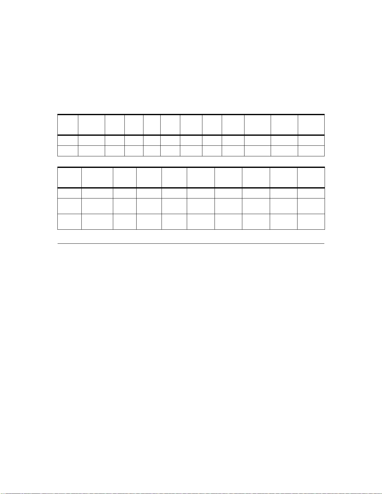
Table 1 and Table 2 provide, at time of publication, the related performance
values.
Table 1. SPEC and LINPACK Performance.
Model CPU Clock
Rate
(MHz)
150 604e 375 32/32 1 15.1 14.5 10.1 9.85 64.8 151.2 255.7
260 POWER3 200 32/64 4 13.2 12.5 30.1 27.6 236.5 248.1 630.0
Table 2. Multiuser Performance
Model CPU Clock
150604e37532/3216.0---260 POWER3
(1-way)
L1
(KB)L2(MB)
L1
Rate
(MHz)
200 32/64 4 10.5 116 111 266 243
Cache
(KB)
SPEC
int95
L2
Cache
(MB)
SPEC
int_
base95
Relative
OLTP
Perf.
SPEC
fp95
SPEC
fp_
base95
SPEC
int_
rate95
LINPACKDPLINPACKSPLINPACK
SPEC
int_base
rate95
SPEC
fp_
rate95
TPP
SPEC
fp_base
rate95
260 POWER3
(2-way)
200 32/64 4 21.0 232 222 509 468
1.6 Industry Trends and Directions
There are many emerging trends and directions in the UNIX hardware
marketplace. Some will be determined as frivolous, and others will become
industry standards. In this section there is a discussion of some key emerging
technologies that may, in the opinion of the authors, become pervasive in the
marketplace.
1.6.1 Microprocess or Future
As applications grow more complex, more processor power is required to give
you acceptable performance. It is easy to predict the following developments
pertaining to the growth of computing power available for the RS/6000.
• Moore’s law will remain true. 1000 MHz processors are already running in
the lab. More importantly, IBM’s use of copper technology and
complementary metal oxide semiconductor (CMOS) fabrication
RS/6000 Introduction 13
Page 32

techniques will continue to bring significant enhancements to the
PowerPC.
• The POWER3 architecture provides a significant impact to the market by:
• Providing SMP scalability not found with POWER2
• Redefining the versatility of a departmental computing solution by
providing outstanding float-point performance with solid integer
performance
• Providing an affordable entry-level 32-bit and 64-bit solution
1.6.2 Universal Seria l Bus
The Universal Serial Bus (USB) is a plug and play peripheral connection for
devices such as keyboards, mice, joysticks, scanners, tablets, printers, and
digital cameras, to name a few. USB could replace the serial and parallel
ports with a single bus.
USB supports many peripherals at one time. Special USB hubs will allow
devices to be daisy-chained together. USB also distributes power to the
attached devices, eliminating the need for dedicated peripheral power
supplies.
Data flow in a USB is bidirectional. Devices can make use of this two-way
communication to report status, or control other peripherals.
1.6.3 The Accelerated Graphics Port
The Accelerated Graphics Port (AGP) is a high-bandwidth 32-bit PC bus
architecture introduced in 1997 by Intel. It provides up to 528 MB/s memory
access to a graphics controller, yielding the bandwidth necessary for complex
tasks such as texturing directly from system memory. AGP is physically
different from the PCI bus and does not replace PCI. AGP uses a
combination of frame-buffer memory local to the graphics controller, as well
as system memory for graphics data storage.
Although the AGP interface is very popular in the PC world, it has not become
a standard. However, the importance of images, video, and graphics is
growing. The next step in this evolutionary path is visual computing.
Visual computing is the convergence of high-performance 3D graphics, video,
and digital imaging technologies to deliver a new class of interactive, intuitive,
and life-like computing experiences to users.
14 RS/6000 43P 7043 Models 150 an d 260 Ha ndb ook
Page 33

1.6.4 IEEE 1394
IEEE 1394 is a transport protocol standard for a high performance serial bus
(also known as FireWire) that is a bus technology for the digital age. More
than 50 companies are supporting this standard. FireWire was originally
developed by Apple Computer. It was started as a specification for the
transmission of digitized video and audio quickly, reliably, and at low cost.
The architecture is scalable and hot-pluggable. Industry consortiums are
moving toward a 1 gigabit data transfer rate.
Like USB, 1394 enables plug-and-play peripheral connectivity and supports
isochronous data transfers. The major difference is data rate. USB ideally
supports slow-speed devices like keyboards. IEEE 1394 is able to handle all
I/O, including printers, DASD, PCI, and IDE devices, as shown in Figure 4.
Figure 4. IEEE 1394 Connections
1.7 Workgroup Conferencing
Workgroup Conferencing Version 1.1.0 for AIX (commonly referred to as
Workgroup) is IBM’s first interoperable and indu stry standards-based desktop
conferencing product that unleashes the real-time videoconferencing
RS/6000 Introduction 15
Page 34

capabilities of IP-based intranet or Internet network environments on
RS/6000 and AIX systems. This full-function AIX videoconferencing
application features an easy-to-use user interface to setup and manage
spontaneous videoconferencing sessions between RS/6000 and other
desktop conferencing products, such as Microsoft NetMeeting, on Windows
and other UNIX systems.
Figure 5. RS/6000 Hardware for Workgroup Conferencing
Customer benefits of this application include:
• Flexibility
Workgroup provides full-function desktop videoconferencing for a variety
of different application scenarios.
• Features
Workgroup was developed using a feature-rich implementation of the
dominant International Telecommunications Union (ITU) Recommendation
H.323 Version 2 industry standards for Packet-Based Multimedia
Communications Systems.
• Interoperability
16 RS/6000 43P 7043 Models 150 an d 260 Ha ndb ook
Page 35

Workgroup was designed to interoperate with AIX, other UNIX, and
Windows H.323-based conferencing systems including other desktop
videoconferencing systems such as Microsoft NetMeeting Version 2.1,
H.323/PSTN Gateways and Gatekeepers.
• Scalability
Workgroup supports point-to-point and multiparty calls in a peer-to-peer
mode. WorkGroup was also designed to participate in large group,
server-based conferencing sessions.
• Ease of use
Workgroup features simple point-and-click dialing access to other desktop
conferencing users with personalized speed-dial or popular directory
server applications.
Workgroup breaks down the barriers of distance:
• Workgroup delivers full-function desktop videoconferencing. By simply
configuring an RS/6000 system with a video capture card, camera, and
connection to an IP network, Workgroup enables AIX Version 4.3.2
customers to host small group videoconferencing sessions without the
expense or complexity of sophisticated videoconferencing equipment or
conferencing servers.
• This new IBM application provides easy access to a variety of
videoconferencing call setup and management features. Using a
high-level user interface, initiating a person-to-person or multi-party
Workgroup videoconference call is almost as easy as dialing a telephone
number. Workgroup features speed-dialing support for frequently called
locations and an automated call history log that contains an ongoing
record of all incoming calls. All necessary speaker, microphone,
do-not-disturb, and video controls are available in an easy-to-use Call
Center workspace. Local and remote video windows are easily detached
from the Call Center workspace and can be resized using certain RS/6000
graphics accelerators, from original size up to full screen video window.
• By exploiting a feature-rich implementation of the ITU-T Recommendation
H.323 Version 2, Workgroup is designed to provide full-function
videoconferencing and interoperates with other H.323 standards-based
videoconferencing systems on AIX, other UNIX, and Windows systems. In
addition, IBM participates in worldwide H.323 interoperability ev ents to
promote Workgroup compatibility with other videoconferencing systems
based on this dominant standard for highly interactive, multimedia
teleconferencing products and services. These H.323 standards, among
others, are also promoted by the International Multimedia
RS/6000 Introduction 17
Page 36

Telec onferencing Consortium, Inc. (IMTC), a non profit corporation
composed of more than 150 members and affiliates from North America,
Europe, and Asia/Pacific. The IMTC organization is actively involved in
promoting open international standards in the development of
interoperable, full-function multimedia teleconferencing solutions.
• Workgroup contains support for popular Lightweight Directory Access
Protocol (LDAP) and Microsoft Internet Locator Service (ILS) database
server applications that reveal other users available for on-line,
videoconference sessions within a corporate intranet or public Internet
network environment.
• WorkGroup Conferencing for AIX, Version 1.1.0 features a full-function
user interface designed for both videoconferencing and the addition of
future desktop conferencing features.
Note
For more information about WorkGroup, visit the following Web site:
http://www.rs6 00 0. ib m.c om /s olu ti on s/int er ac tiv e
Workgroup Conferencing for AIX, Version 1.1.0 is included in the Bonus Pack
for AIX 4.3.2 CD, which is shipped with the base AIX operating system.
1.8 Year 2000
As a global organization, IBM has been supporting customers around the
world in all the major phases of Year 2000 transition period. The reach of
information systems has continued to expand at a rapidly increasing pace
and the breadth of the information that can be distributed is growing at an
equally rapid rate. Keeping in mind the Year 2000 challenges, the pressure
on the IT organization is increasing. As business must achieve unmatched
levels of customer satisfaction and competitive advantage, the IT
organization is challenged to continue to deliver advanced uses of
information technology.
The IBM RS/6000 43P 7043 Models 150 and 260 do not have date
dependencies and are therefore Year 2000 ready. When used in accordance
with its associated documentation, it is capable of correctly processing,
providing, and/or receiving date data within and between the 20th and 21st
centuries, provided all other products (for example, software, hardware and
firmware) used with the product properly exchange accurate date data with it.
18 RS/6000 43P 7043 Models 150 an d 260 Ha ndb ook
Page 37

Further information can be found on IBM’s Year 2000 webpage at:
http://www.ibm.com /year2000.
Figure 6. RS/6000 Models 150 and 260 are Year 2000 Ready
RS/6000 Introduction 19
Page 38

20 RS/6000 43P 7043 Models 150 an d 260 Ha ndb ook
Page 39

Chapter 2. Hardware Overview
This chapter introduces the standards and architectures that are shared
between the RS/6000 43P Series systems. The discussion encompasses the
following topics:
• PowerPC microprocessor RS/6000 Platform Architecture (RPA)
• Hardware design
• Processor subsystem
• SMP hardware characteristics
The general architectures discussed in these sections help build an overall
appreciation for RS/6000 hardware.
2.1 The RS/6000 Platform Architec ture
The RS/6000 Platform Architecture (RPA) introduces a comprehensive
computer system hardware-to-software interface definition, combined with
minimum system requirements, that enables the development and porting of
software to a range of compatible computer systems from portables through
servers. These systems are based on the PowerPC microprocessor, as
defined in the
Processors. Both the RS/6000 43P 7043 Model 150 and Model 260 are RPA
compliant.
PowerPC Architecture: A Specification for a New Family of RISC
2.1.1 The RS/6000 Platform Architecture Introduction
The RPA is essentially a combination of its predecessor, the PowerPC
Microprocessor Common Hardware Reference Platform (shortened by the
industry to be known as the PowerPC Platform) and some IBM architecture
extensions. This platform architecture officially came into being in August of
1997.
Prior to IBM’s RPA, an alliance existed between Apple, IBM, and Motorola
that developed a common hardware platform with the purpose of defining a
system that would become the pervasive open industry standard, from single
user to server configurations. As a result of this alliance, the PowerPC
Platform emerged. The PowerPC Platform, previously known as CHRP, is a
superset of the earlier PowerPC Platform Specification (PRep) system
architecture. The Apple, IBM, and Motorola alliance is no longer functional.
A key benefit of the RPA specification is the ability of hardware platform
developers to have degrees of freedom of implementation below the level of
© Copyright IBM Corp. 1998 21
Page 40

architected interfaces and therefore have the opportunity for adding unique
value. This flexibility is achieved through architecture facilities including:
• Device drivers
• Open Firmware (OF)
• Run-Time Abstraction Services (RTAS)
• Hardware abstraction layers
2.1.2 Platform Topology
Figure 7 on page 23 shows a general platform topology of the RS/6000
Platform Architecture. All platforms (from notebooks to high-end servers)
consist of one or more PowerPC microprocessors, a volatile system memory
separate from other subsystems, and a number of I/O devices, that may
initiate transactions to system memory.
The processors are linked over the primary processor bus/switch to each
other, to the system memory, and to one or more host bridges (host bridge 0
must be a PCI host bridge).
In general, I/O devices do not connect to the primary processor bus/switch.
The host bridges connect to secondary buses that have I/O devices
connected to them. In turn, one or more bus bridges may be employed to
tertiary buses (for instance ISA or PCI) with additional I/O devices connected
to them. Typically, the bus speeds and throughput decrease and the number
of supportable loads increases as one progresses from the primary processor
bus to more remote buses.
There are variations to this topology that are likely to occur and are therefore
worth describing in the following list. The architecture describes interfaces
not implementation. The logical software model must remain the same, even
if the physical topology is different.
• In a smaller platform, the host bridge, memory, or an I/O device may be
integrated into a single chip. In this case, the topology would not look like
Figure 7 on page 23, from a chip point of view, but, instead, would be
integrated onto the single chip.
• In a larger platform, secondary buses may be implemented, with two or
more host bridges, as two or more parallel expansion buses for
performance reasons. Similarly , tert iary buses may be two or more parallel
expansion buses off each secondary bus. This is indicated by the dots
near the host bridge and the bus bridge.
22 RS/6000 43P 7043 Models 150 an d 260 Ha ndb ook
Page 41

• In a high performance platform, with multiple processors and multiple
memories, a switch may be employed to allow multiple parallel accesses
by the processors to memory. The path through the switches would be
decided by the addressing of memory.
PowerPC Processor
. . .
(L1/L2 Ca che)
Primary Processor Bus/Switch
System Memory Host Bridge
Secondary Bus (PCI)
I/O Device
. . .
I/O Device
PowerPC Processor
(L1/L2 Cache)
. . .
Bus
Bridge
. . .
I/O Device I/O Device
Figure 7. General Platform Topology
Tertiary Bus (ISA or PCI)
. . .
Hardware Overview 23
Page 42

2.1.3 RS/6000 Pla tform Architec ture Achievem ents
The RS/6000 Platform Architecture specification achieves the following:
• Creates a stable platform architecture to be used by all RS/6000 platforms
based on PowerPC processors and PCI I/O bus (and may contain other
I/O buses in addition to the PCI bus).
• Creates an architecture that allows platforms to operate with a previous
version of AIX (n-1 capability).
• Leverages existing and future industry-standard buses and interfaces.
Existing bus architectures have a proven level of performance and
function. Established industry-standard interfaces (for example, SCSI,
IDE, LocalTalk, Ethernet) and newer bus architectures, interfaces, and
protocols (PCI, PC Card, IrDA, to name a few) provide higher levels of
performance or utility that are not achievable by the older standards. The
architecture allows platform and system designers to determine which
buses, interfaces, and protocols best suit their target environment.
• Provides a flexible address map. Another key attribute of this specification
is the relocatability of devices and subsystems within the PowerPC
address space. Subsystem address information, which defines where I/O
devices reside, is detected by the Open Firmware and passed to the
operating systems in the device tree. The architecture accommodates the
use of multiple identical buses and adapters in the same platform without
address conflicts.
• Builds upon the Open Firmware boot environment defined in IEEE 1275,
IEEE Standards for Boot (Initialization Configuration) Firmware, Core Requirements and
Practices, IEEE part number DS02683, ISBN 1-55937-426-8. (To order
copies of IEEE standards, load the following Web site:
http://standards.i eee.org/index.ht ml).
In the past, the abstraction approach for the operating system used
platform description information discovered by a legacy boot process and
passed it to the operating system in data structures.
• Architects the control of power management by the operating system. It is
important that the combination of hardware and software be allowed to
minimize power consumption through automatic or programmed
power-saving methods. Power management of systems will reduce the
operational cost for the user and reduce the impact of the system on the
environment.
• Provides an architecture that can evolve as technology changes.
• Minimizes the support cost for multiple AIX versions through the definition
of common platform abstraction techniques. Common and compatible
24 RS/6000 43P 7043 Models 150 an d 260 Ha ndb ook
Page 43

approaches to the abstraction of hardware will reduce the burden on
hardware developers who produce differentiated machines.
• Architects a mechanism for error handling, error reporting, and fault
isolation. The architecture provides for the implementation of more robust
systems if desired by the system developers.
• Architects a mechanism for dynamic reconfiguration of the hardware.
2.1.4 RPA Minimum System Requirements
Table 3 contains the RPA compliance, minimum system requirements for the
workstations addressed in this publication.
Table 3. RPA Minimum System Requirements
SUBSYSTEM SPECIFICATION REQUIRED SUPPORT
Processor PowerPC microprocessor R Y e s
Minimum system memory 8 MB expandable to at least 32MBR Yes (128 MB min)
Firmware storage Sized as needed R Yes (1 MB Flash)
Non-volatile memory 8 KB R Yes (64 KB)
External cache Recommended for performance O Yes (1 MB)
Hard disk
1
Floppy
1
SCSI R Yes
3.5" 1.44 MB MFM
Media sense
Manual eject
O
R
R
R
Yes
Yes
Not supported
Yes
CD ROM
Alphanumeric input device
Pointing device
Required definition
R - Required
O - Optional
1
4X speed
ISO9660
Multi-session
1
PS/2 keyboard interface
Terminal
2 buttons
PS/2 Interface
O
R
R
R
R
R
O
R
R
R
Yes
Y es 32X Speed
Yes
Yes
Yes
Yes
Yes
Yes
Yes (3 button)
Yes
Hardware Overview 25
Page 44

SUBSYSTEM SPECIFICATION RE QUIRED SUPPORT
Audio 16-bit stereo, 22.05 and 44.1
KHz, full duplex
Tone R Yes
Graphics default
1024x768
Bi-Endian
640x480x8 LFB
VGA
Real-time cl ock R Yes
Serial port
Parallel port P1284 + ECP mode R Yes
Network O Yes
Interrupt controller Open PIC
Direct memory access
(DMA)
Power management States as defined O NO
Infrared IrDA O NO
1
16550
8259 tree
ISA R Yes
RYes
R
R
R
R
O
R
R
R
R
Yes
Yes
Yes
Yes
Yes
Yes
Yes
(Ethernet 10/100)
Yes
Yes
Required definition
R - Required
O - Optional
1
See the published CHRP document for the original value of this row for
platforms that need to support Apple Mac OS.
2.2 The Hardwa re Design
The designs of the Model 150 and the Model 260 differ slightly and will
therefore be addressed in separate sections.
2.2.1 Hardware Design for the RS/6000 43P 7043 Model 150
The RS/6000 Model 150 is a uni-processor system that utiliz es the PowerPC
604e processor running at 375 MHz. It supports an integrated 1 MB
26 RS/6000 43P 7043 Models 150 an d 260 Ha ndb ook
Page 45
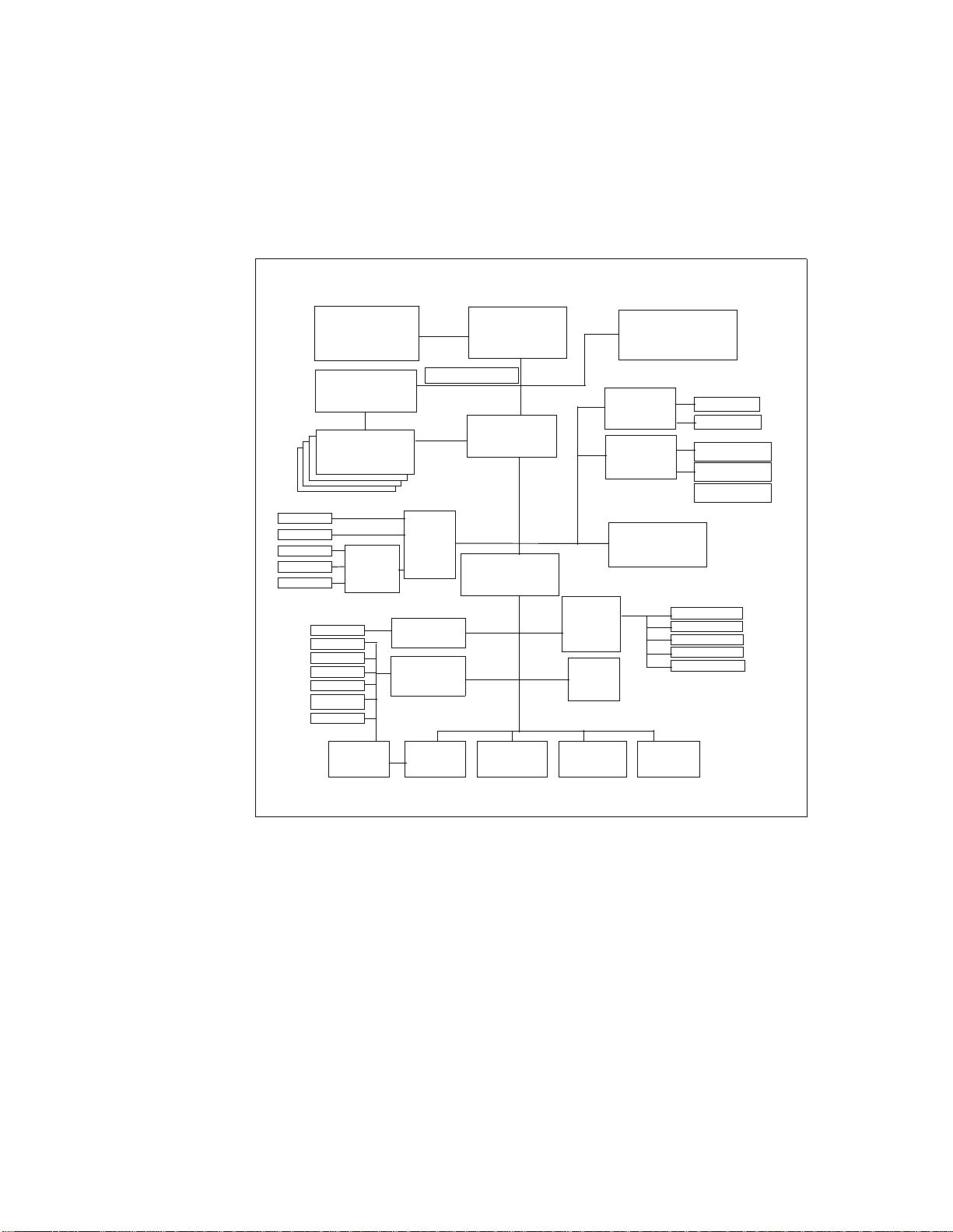
parity-checked synchronous L2 cache. The Model 150 also features an
enhanced memory controller that uses ECC SDRAM memory.
The local system bus on the RS/6000 Model 150 is a 60X bus running at 83
MHz. This bus is 64 bits wide (with an additional 8 bits for parity) and is
synchronous. The processor clock and regulator card reside as one unit,
namely the OVdd/Vdd/PLL card. This is illustrated in the planar design of the
Model 150 in Figure 8.
OVdd/Vdd/PLL
Ctrl/Buffer
ECC SDRAM
PCI Slot 2
PCI Slot 3
PCI Slot 1
PCI Slot 4
PCI Slot 5
Tablet
Parallel
Serial 1
Serial 2
Floppy
Keyboard
Mouse
IBM
Card
ECC
604e-375 MHz
IPGA
Local bus 83 MHz
PCIB/MC
DIMM
RISER
PCI/PCI
Bridge &
Secondary
PCI Bridge
NVRAM Logic Front Panel
32 KB
Clock
Drivers
National
UART 16550
National
PC87308
Unit
PCI-to-ISA
PCI Bus 33 MHz
Bridge
ISA Bus
8 MHz
Controller
Ultra SCSI
Business
Audio
1 MB
Flash
ROM
Enhanced
Security
Integrated 1 MB
Parity L2 Cache
100/10
Ethernet
IBM MPIC
Controller
Headphone
Speaker
Line Out
Line In
Microphone
Power
Mgmt
Enet RJ45
Enet AUI
Int Ultra SCSI
Repeater
Ext Ultra SCSI
Figure 8. Planar Block Diagram of the RS/6000 Model 150
In the Model 150, the 60X bus runs from the PowerPC 604e processor and
connects to an enhanced memory controller chip, which has a processor
Hardware Overview 27
Page 46

system interface of a 64-bit data bus and a 32-bit address bus. This highly
integrated chip acts as both a PCI bridge and a memory controller. It contains
the system bus arbitration, provides support for full memory coherency, and
pipelining of processor accesses.
Information may be routed from the memory chip to main memory, using the
memory bus, or to I/O devices using the I/O bus.
In the Model 150, the memory bus runs at 83 MHz. The memory subsystem
supports up to four industry-standard DIMM sockets with supported
capacities of 64, 128 and 256 MB. The memory DIMM can be populated in
any order. An ECC controller/buffer, running at 83 MHz, handles high
performance ECC operation with SDRAM memory, and parity operation on
the system bus. Single bit errors are corrected, while double bit errors are
detected.
For access to I/O devices, the PCI bus is used, running at 33 MHz. Devices
such as the integrated Ethernet adapter, the integrated Ultra SCSI controller
and the IBM Multiprocessor Interrupt Controller (MPIC) are all attached to the
PCI bus. This bus also leads to the PCI-to-ISA bridge, which the Model 150
uses as the system I/O bridge. The PCI-to-ISA bridge supports a PCI bus
controller interface to enhanced IDE drives, an ISA bus bridge, and an
XD-bus interface (for support of flash EPROM).
The ISA bus runs at 8 MHz and provides support for the following:
• Business audio controller
• Tablet port
• Native I/O controller (for diskette controller, serial ports, parallel port)
• 1 MB Flash ROM (to contain the IPLROS Open Firmware)
28 RS/6000 43P 7043 Models 150 an d 260 Ha ndb ook
Page 47

2.2.2 Hardware Design for the RS/6000 43P 7043 Model 260
Figure 9 on page 30 shows the system block diagram for the Model 260. This
workstation is a 1- or 2-way symmetric multiprocessing system using the
64-bit 200 MHz POWER3 processor. The processor subsystem is
implemented on pluggable processor cards. If two cards are installed in the
system, they must both be the same type or the system will not power on.
The POWER3 processor card has two main components:
• POWER3 chip itself
• 4MB L2 cache
The controller for the L2 cache is integrated on the POWER3 chip, so there is
no need for the separate X5 cache that exists on some RS/6000 systems,
such as the Model F50.
Three main buses are used in this system design, namely:
• System bus
• Memory bus
• I/O bus
The system bus within the RS/6000 Model 260 is an SMP 6XX high
performance bus. The POWER3 processor delivers the SMP server bus
directly, and therefore can have direct connectivity to the memory controller
chip. Each POWER3 CPU has two paths leading from the processor, namely
an address bus (64-bit) and a data bus (128-bit), highlighting the true split
transaction capability of the 6XX bus. The address bus of one CPU merges
with the address bus of the other to create a single input to the Address
Controller unit. Similarly, the data bus of one CPU merges with the data bus
of the other, creating a single input to the Data Controller unit.
The Address Controller unit and the Data Controller unit, both semi-custom
CMOS5S chips, are separate partitions of a recently developed enhanced
memory controller unit. This chipset supports running the bus at 100 MHz. A
clock distribution chip was designed and placed on each memory card to
achieve 100 MHz performance.
Hardware Overview 29
Page 48

POWER3
200 MHz
POWER3
CPU Card
32 bytes
@ 200 MHz
4 MB L2
POWER3
200 MHz
POWER3
CPU Card
32 bytes
@ 200 MHz
4 MB L2
6XX Address
100 MHz
3 cycle tenure
Memory
Address
planar B
ISA Bridge
W83C553
Addr/Cntl
Memory Card
256 MB - 2 GB
Memory Data Bus
16 bytes @ 100 MHz
Memory Card
256 MB - 2 GB
Integrated
Service Processor
Data
PCI Bridge
6XX Data Bus
16 Bytes
100 MHz
6XX-MX Bus
66 MHz
AB4
Clock
planar A
PCI Bridge
2 PCI Slots
64-Bit / 50 MHz
Super I/OAudio
Figure 9. RS/6000 High Level System Block Diagram (Model 260)
The memory controller chip can act as the system interrupt controller, or can
pass interrupts through to an external device. Two distinct interrupt protocols
30 RS/6000 43P 7043 Models 150 an d 260 Ha ndb ook
U-SCSIU-SCSI10/100 ETH
3 PCI Slots
32-Bit / 33 MHz
Page 49

are supported, namely the RISC System/6000, or the industry standard
OpenPIC.
Special attention was given to providing support for the memory controller
unit in the Model 260:
• Benchmark traces were used to fine-tune the buffer structure and queue
depths.
• The traces were also utilized to remove any wasted or unused cycles
internal to the memory controller.
The output from the memory controller function may be routed to main
memory, using the memory bus, or to I/O devices, using the I/O bus.
To transport addressing information from the address controller to main
memory, the memory address bus is used. Data is passed from the data
controller to main memory using the memory data bus.This bus supports
sustainable memory bursts across a 128-bit data bus, which translates to a
read bandwidth of 1.6 GB/s at 100 MHz. The memory bus drives up to four
memory cards populated with non-buffered synchronous dynamic random
access memory (DRAM) standard dual in-line memory modules (DIMMs).
The SDRAM sizes supported are 16 MB, 64 MB, 128 MB, and 256 MB, with
64 MB being the minimum total system memory supported. Two error
checking and correction (ECC) codes are supported by this memory
controller unit. The first supports single bit correction, double bit detection,
and four bit packet detection. The second supports single bit correction, two
bit packet correction, and double packet detection.
For access to I/O devices, the 6XX-MX I/O bridge bus is used. This bus is a
64-bit, time-multiplexed address and data bus, and can attach a variety of I/O
bridge chips. It runs asynchronously to the system and memory bus, and will
support speeds up to 75 MHz, translating to a sustainable read bandwidth of
533 MB/s. From the 6XX-MX bus, information passes through the PCI bridge
chip, where it is converted to PCI format for use with PCI devices. Each PCI
controller is able to communicate with a limited number of slots, so additional
PCI controllers are required to support a large number of PCI cards. Also,
specifications for 64-bit slots and standard 32-bit slots will often require
specialized PCI controllers.
The ISA bridge located on the I/O backplane allows conversion from PCI to
ISA, enabling the use of native ISA devices. The integrated service
processor, also located on the I/O backplane, allows for improved reliability,
availability, and serviceability features.
Hardware Overview 31
Page 50

2.3 Bus Architecture
The following sections cover the different bus architectures that exist on the
RS/6000 43P 7043 Models 150 and 260.
2.3.1 The PCI Bus Arch itecture
The Peripheral Component Interconnect (PCI) is a specification standard for
computer bus implementation developed by the PCI Special Interest Group
(PCI-SIG), led by a group of companies including Compaq, Digital, IBM, Intel,
and NCR. There are now over 300 companies in the PCI-SIG supporting the
architecture and currently producing PCI products.
The goal is to provide a common system-board bus that could be used in
personal computers, from laptops to servers. It is envisioned as a local
system-board bus that would serve as a common design point, supporting
different system processors as the various processors evolve over time. This
is much like operating systems that have defined application binary interfaces
(ABIs) so that applications need not change with each generation of the
operating system. The PCI local bus would serve as a common hardware
interface that would not change with different versions of microprocessors.
2.3.1.1 PCI Sp ecification Revisions
According to PCI Specification Revision 2.0, the PCI bus operates on 32- or
64-bits of data at a clock speed of 33 MHz. However, as the speed of
processors continues to increase and devices such as video adapters require
more bandwidth, bus speeds must also increase to avoid data bottlenecks.
Consequently, PCI Specification Revision 2.0 has been superseded by PCI
Local Bus Specification Revision 2.1, which introduces support for a 66 MHz
bus operation speed, doubling the throughput of the former 33 MHz standar d.
The RS/6000 43P Model 260 complies with PCI Local Bus Specification
Revision 2.1. IBM’s implementation of the 64-bit bus slot uses a clock speed
of 50 MHz. The Model 150 is PCI 2.0 compliant.
Under PCI Specification Revision 2.1, the 66 MHz bus operation speed is an
optional feature and is backward-compatible with 33 MHz PCI devices and
buses. If a 66 MHz capable PCI device is installed in a 33 MHz PCI bus, the
device must operate at 33 MHz. Likewise, if any 33 MHz PCI devices are
installed into a 66 MHz PCI bus, the PCI bus must operate at 33 MHz.
32 RS/6000 43P 7043 Models 150 an d 260 Ha ndb ook
Page 51

2.3.1.2 PCI F eatures and Benef its
The PCI bus architecture has many advantages including the following:
• High data transfer speed
• Processor independence
• Cross-platform compatibility
• Multi-bus support
• Plug and Play
• Investment protection
2.3.2 The ISA Bus Arch itecture
The Industry Standard Architecture (ISA) is the most widely used system bus
in the PC industry . Initially, it had no official definitions or standards. However,
its specifications have since been defined by the Institute of Electrical and
Electronics Engineers (IEEE) standards group.
The ISA bus allows a transfer rate of up to 8.3 MB/s. Transfers over the ISA
bus are synchronized around 8 MHz, and they usually take a minimum of two
cycles of the bus clock to perform a data transfer. Since the data path of an
ISA bus is 16 bits wide, up to 2 bytes may be transferred during each
transaction.
On the RS/6000 43P Series Model 150 and Model 260 computers, the ISA
bus is used to attach internal devices such as the diskette drive. No ISA slots
are provided for the addition of non-native ISA devices.
There is a disadvantage in trying to connect the processor to the ISA bus
directly. The processor's speed is reduced to match the slow ISA bus speed.
Thus, the systems cannot take advantage of a fast processor.
To avoid this dis advantage, the PCI local bus is used as the primary system
bus and the ISA bus as an expansion bus. This way, the system can take
advantage of the high-speed data transfer provided by the PCI bus when
communicating with the processor and memory. On the other side, through
the PCI-ISA bridge, the bus clock can be reduced to match the ISA bus
requirements.
Table 4 provi des the bus specification for different architectures and
compares them to the PowerPC processor's speed.
Table 4. PowerPC and Bus Specification
Specification PowerPC PCI ISA(8) ISA(16) EISA
Procssor
Speed
166, 200
233, 375
Hardware Overview 33
Page 52

Specification PowerPC PCI ISA(8) ISA(16) EISA
Data Bus 64 64 8 16 16/32
Address Bus 32 64 20 24 24/43
Bus Clock 66 MHz
Interrupts 4 6 11 11
DMA Channel busmaster 3 7 7
2.3.3 The 60X and 6 XX Bus
The 60X bus was designed to provide a common interface that supplies
communication between processors, memory controllers, and high-speed I/O
devices. Arbitration on the bus is performed by a central, off-chip arbitrator.
The 60X bus provides the capability to build an SMP system with the MESI
protocol. This bus is also known as the MP System Bus.
The 60X bus uses separate address and data buses and a variety of control
and status signals. The address bus is 32 bits wide (with 4 bits parity) and the
data bus is 64 bits wide (with 8 bits parity). These separate address and data
buses run independently, allowing split transactions. The bus is synchronous,
with all timing relative to the rising edge of the bus clock. Inputs are sampled,
and outputs are driven from this edge.
It is through this bus that the two-way SMP’s processors are attached,
memory is accessed, and cache snooping is achieved.
83 MHz
100 MHz
33 MHz
(32-bit)
4.7 MHz 8.3 MHz 8.3 MHz
2.3.4 The 6XX-MX I/O Bus
The 6XX-MX I/O bus is a high-performance bus designed to be used as a
high-end I/O bus for mid- and high-range systems. It will accommodate both
32- and 64-bit processors with real memory addressing extending beyond 32
bits.
The requests and replies are tagged, allowing for out-of-order replies, which
are common for programmed I/O to another bus or in a non-uniform memory
access (NUMA) environment.
This bus must have a bridge chip to translate a 6XX or 60X transaction with
the corresponding operation. Due to the 66 MHz PCI capability as defined in
the PCI Local Bus Specification (Revision 2.1), local bus performance has
increased from 264 MB/s to 528 MB/s for 64-bit transfers.
34 RS/6000 43P 7043 Models 150 an d 260 Ha ndb ook
Page 53

2.3.5 The X-Bus
The X-Bus is an 8-bit ISA subset bus used to attach several common
subsystems to the PCI-based RS/6000 servers. The following components
are attached to this bus:
• The Keyboard/Mouse controller
• Real-Time Clock and Non-volatile RAM
The functions of Real-Time Clock (RTC) and Non-volatile RAM (NVRAM)
are integrated into a single component in the PCI-based RS/6000 servers.
This component also supplies the logic required to perform the function of
powering the system on at a designated time. The component is operated
from a lithium battery on the board so that all time-keeping functions
continue to work while system power is turned off.
• Mini-Support Processor (I
The Mini-Support Processor is a minicontroller that is imbedded into the
I/O planar of the PCI-based RS/6000 servers. It allows the PowerPC
processor access to VPD, operator panels and other I
devices.
2.4 The Process or Subsystem
Since its inception, the RS/6000 product line has used a number of different
processor designs, the original implementation being the POWER
architecture. The most recent development, however, is the POWER3
processor that is implemented in the RS/6000 43P 7043 Model 260. The
Model 150 uses the PowerPC 604e chip.
2
C Controller)
2
C bus-attached
2.4.1 The POWER 3 Microproce ssor
The POWER3 microprocessor introduces a new generation of 64-bit
processors especially designed for high performance and visual computing
applications. POWER3 processors will replace the POWER2 and the
POWER2 Super Chips (P2SC) in high-end RS/6000 workstations and
technical servers.The RS/6000 43P 7043 Model 260 workstation features the
POWER3 microprocessor.
2.4.1.1 Pro cessor Overview
The POWER3 implementation of the PowerPC architecture provides
significant enhancements compared to the POWER2 architecture. The SMP
capable POWER3 design allows for concurrent operation of fixed-point
instructions, load/store instructions, branch instructions, and floating-point
instructions. Compared to the P2SC, which reaches its design limits at a
Hardware Overview 35
Page 54

clock frequency of 160 MHz, POWER3 is targeting up to 600 MHz by
exploiting more advanced chip manufacturing processes, such as copper
technology . The first POWER3 based system, RS/6000 43P 7043 Model 260,
runs at 200 MHz.
Features of the POWER3, exceeding its predecessor (P2SC), include:
• A second load-store unit
• Improved memory access speed
• Speculative execution
Figure 10 shows the POWER3 microprocessor architecture.
Figure 10. POWER3 Microprocessor Logical Block Diagram
36 RS/6000 43P 7043 Models 150 an d 260 Ha ndb ook
Page 55

The two additional execution units give POWER3 a peak instruction rate of
eight instructions per cycle (two floating-point, two load/store, two
single-cycle integer, a multi-cycle integer, and a branch instruction).
Significant investments in the chip’s memory interface have been made in
order for the POWER3 to have a sustainable execution rate of four
instructions per cycle (two load instructions and two floating-point). Although
its 64 KB data cache is only half the size of the P2SC’s, its advanced core, a
dedicated second level (L2) cache, and aggressive prefetching mechanisms
improve the memory access speed. The initial POWER3 implementation
applies 4 MB (L2) cache.
POWER3 is defined by the following specifications:
• POWER3 microprocessor running at:
– 200 MHz on RS/6000 Model 260
• Superscalar design with integrated integer, floating-point, and branch units
• 32 KB instruction cache
• 64 KB 128-way set associative data cache
• 64-bit memory interface with 64-bit addressing
• Real memory support for up to 4 GB (3 GB on AIX 4.2.1)
2.4.2 The PowerPC 604e Microp rocessor
The RS/6000 43P 7043 Model 150 workstation features the PowerPC 604e
microprocessor. The 604e is an equivalent, but enhanced derivative of the
604. Enhancements to the PowerPC 604e, exceeding its predecessor
(PowerPC 604), include:
• Doubled L1 cache (instruction and data)
• Higher clock frequencies
• Built-in performance monitor
The superscalar design of the 604e provides up to four instructions to be
dispatched per cycle and four to complete at once, with one store and one
branch per cycle.
Figure 11 on page 38 shows the PowerPC 604e microprocessor architecture.
Hardware Overview 37
Page 56

Fetch Unit
Instruction MMU/Cache Unit
Branch Unit
Units
Dispatch/Completion Buses
Decode/Dispatch & Completion
Floating
Point Unit
Load/Store
Unit
Integer
Unit
Floating Point
Register File
Rename Buffer
General Purpose
Register File
Rename Buffer
Memory Queues Data MMU/Cache
COP/JTAG Bus Interface Unit
JTAG Bus Address Bus Data Bus
Figure 11. PowerPC 604e Microprocessor Logical Block Diagram
A 604e is defined by the following specifications:
• PowerPC 604e microprocessor running at:
– 375 MHz on RS/6000 Model 150
• Superscalar design with integrated integer, floating-point, and branch units
38 RS/6000 43P 7043 Models 150 an d 260 Ha ndb ook
Page 57

• 32 KB four-way set-associative instruction cache
• 32 KB four-way set-associative data cache
• 64-bit memory interface with 32-bit addressing
• Virtual memory support for up to 4 petabytes (2
• Real memory support for up to 4 gigabytes
• ˜5.1 mil lion transis tors
• Nap power management mode
• JTAG bus (IEEE 1149.1) for RAS
2.5 SMP Hardware Characteristics
Sharing resources is probably the main technical issue in the design of a
symmetric multiprocessor (SMP) system. To support symmetric
multiprocessing, specific techniques must be provided at the hardware level
and the software level. This section introduces the memory hierarchy concept
and some of the techniques used to solve resource-sharing and contention
issues.
2.5.1 Memory Hierarc hy
In order to improve the hardware performance of a system (uniprocessor
(UP) or mulitprocessor (MP), different levels of memory are used. These
different levels of memory can be ordered according to their access time and
capacity.
52
)
If you look at the different types of memory available on a typical system, you
will find the CPU registers at one end. They are fast but small, and have a
high cost per bit. At the other end, you will find the disks, which are slow but
have a very low cost per bit, allowing for high disk storage capacity.
In most UP or SMP implementations, a first level of cache (L1) lies between
these two ends. L1 cache is a fast form of memory with a small capacity. The
number of CPU cycles that are needed for the processor to load data from L1
depends on the L1 implementation, In the PowerPC implementation, L1 is on
the CPU chip itself, so it takes only one cycle to load data from L1. When the
L1 cache is outside the processor chip, several cycles are required to load
data from L1. A typical L1 capacity is around 32 to 64 KB.
You might also find a second level of cache (L2), which is another form of
high-speed memory. It takes about two to ten cycles to load data from L2.
Hardware Overview 39
Page 58

The main memory is the third level of memory. Its access time is slow in
comparison to L1 and L2, but much faster than disks. Twenty to fifty CPU
clock cycles are needed to load data from the memory, and the capacity can
reach several gigabytes.
Figure 12 shows the relationship between proximity of memory to the
processor versus the number of cycles required to access it.
Processor
1 cycle 32-64 KB
L1 Cache
L2 Cache
2-10 cycles
256 KB - 4 MB
Memory
20-100 cycles
n X GBs
Disk
750 K - 1.5 M cycles
Figure 12. Memory Hierarchy
2.5.1.1 Cache Hit versus Cache Miss
When a CPU fetches a memory address, if the data is found in the cache, it is
a cache hit. Otherwise, it is a cache miss. If a cache miss occurs, the data is
loaded from main memory to the CPU and stored in the cache to take
advantage of the higher speed of the cache for a future fetch of the same
memory address. The hit ratio is the percentage of cache hits. Logically, the
higher the hit ratio, the better the syst em perfor mance. All RISC System/6000
computers use a scheme called set associativity to reduce the number of cache
misses.
n X TBs
40 RS/6000 43P 7043 Models 150 an d 260 Ha ndb ook
Page 59

2.5.1.2 Set Associati vity
Set associativity is a mechanism that allows for more efficient sharing of the
L1 data cache among multiple programs running simultaneously. One of the
main differences between the POWER3 and the POWER2 (also PowerPC)
architectures is the way set associativity is implemented. PowerPC has a
4-way set-associative data cache, while POWER3 has a 128-way
set-associative data cache.
To gain a better understanding of set associativity, the concept of cache lines
needs to be introduced. A cache line is the basic unit of transfer between
main memory of cache. It is 128 bytes long on POWER3.
Conceptually, memory is sectioned into contiguous 128-byte lines, each one
starting on a cache-line boundary whose hardware address is a multiple of
128. The cache is similarly sectioned and all data transfer between cache and
memory is in units of these lines. If, for example, a particular floating point
number is required to be loaded into a floating point register, so that
computation may be done with it, then the whole cache line containing that
number is transferred from memory to cache.
Figure 13 shows the L1 data cache mapped onto memory, using POWER2,
while Figure 14 on page 42 shows it using POWER3.
Figure 13. The 4-Way Set Associative PowerPC/POWER2 L1 Data Cache
Hardware Overview 41
Page 60

Figure 14. The 128-Way Set Associative POWER3 L1 Data Cache
Each cell represents a cache line; each column is called a congruence class.
Figure 13 on page 41 contains 128 congruence classes. There are four rows
in the cache area of the figure. Each of these rows contains 128 cache lines
of 128 bytes each (128 x 128 = 16 KB).
Any particular line from memory may only be loaded into a cache line in the
same congruence class: for POWER2, into one of only four locations; for
POWER3, into one of 128 locations.
Generally, when a new line from memory is loaded into the cache, existing
data must be displaced. If the previous contents of the line have been
modified, the line must be stored back into memory. The algorithm used by
the hardware for selecting which cache line to use is an approximation of
Least Recently Used on POWER2, and is Round-Robin on POWER3.
The set associative structure of the cache can lead to a reduction in its
effective size. Suppose successive data elements are being processed that
are regularly spaced in memory (that is with a constant stride). With the
POWER2 cache, the worst case is when the stride is exactly 16 KB (128 lines
X 128 bytes each) or a multiple of 16 KB. In this case, all elements will lie in
the same congruence class and the effective cache size will be only four
42 RS/6000 43P 7043 Models 150 an d 260 Ha ndb ook
Page 61
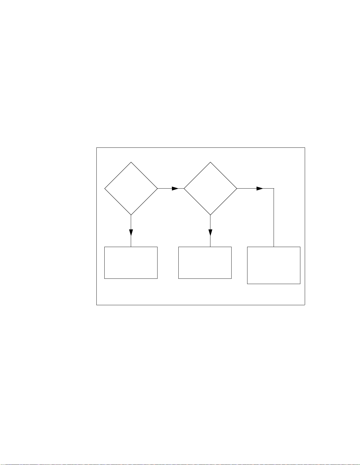
cache lines (since any particular line from memory may only be loaded into a
cache line in the same congruence class). This effect happens with strides
that are a multiple of a power of two.
The POWER3 cache, with its much greater degree of set associativity, is
much less susceptible to this problem than the POWER2 cache. Strides of
multiples of 1024 bytes will cause all the data to be in the same congruence
class but will only cause a reduction in apparent cache size of a factor of 4.
Odd multiples of 512 will halve this effective size. This is, however, minor
compared with the possible reduction by a factor of 128 on POWER2.
2.5.1.3 Effect s of L1 Cac he Miss es on Perfo rmance
The effects of cache misses on performance for POWER3 (the Model 260)
can be illustrated in Figure 15. A load instruction is to be performed to a
floating-point register (assume data is already resident in memory).
Is the data in
L1 cache?
Yes
Load in FloatingPoint Register
No
Is the data in
L2 cache?
Yes
Load in FloatingPoint Register
No
Data in memory
only . Load in
Floating-Point
(Takes 1 cycle)
(Takes 6-7 cycles)
Register.
(Takes 36 cycles)
Figure 15. Loading Instructions from Memory to a Floating-Point Register
If the data is in memory only, it takes about 36 cycles; if it is in L1 cache, it
takes one cycle. That is, the cost of a cache miss to memory is 35 cycles. The
same timing applies to storing data from registers into memory. If the store is
Hardware Overview 43
Page 62

into a previously unreferenced line, the complete line must be fetched from
memory first before the new value can be stored into it. If a cache line is
overwritten by newly accessed data, then, if the data from the old line is
needed again, it must be reloaded and another cache miss taken.
2.5.1.4 Cach e Line Pr efetch
Because of the relatively large number of cycles needed for a cache miss,
POWER3 has a mechanism for mitigating the performance impact for
sequentially accessed data. For up to four streams of data, the hardware
attempts to detect sequential access and initiates the loading of subsequent
lines in parallel, so they stream into cache behind the first line without waiting
for the miss to occur. This important feature of POWER3 is not present on
POWER2.
2.5.1.5 Cach e Coheren cy Prob lem
In an SMP, all of the processors have their own cache to improve data
locality. Only the main memory is shared. Since caches are not shared, it is
necessary to keep all the processors’ caches coherent. The coordination of
current versus stale data between processors is called cache coherency and is
one of the most important issues when designing an SMP system.
Consider an application that runs on two processors, processor 1 and
processor 2, as shown in Figure 16.
processor 1
cache A
0123:
Figure 16. SMP Cache Coherency Problem
44 RS/6000 43P 7043 Models 150 an d 260 Ha ndb ook
A
processor 2
cache B
memory
Page 63

Assume that processor 1 loads into its cache memory address 0x0123, which
happens to contain the character A. Then processor 2 writes B into address
0x0123. If processor 1 wants to load address 0x0123 again, what will
happen? In a naive implementation, processor 1 will see the value A in its
cache and load that value because it does not know that processor 2 has
already changed the same memory address i n its c ache. This i s called the
cache coherency problem.
2.5.1.6 Snooping
One solution to the cache coherency problem is snooping. Snooping is
hardware logic that is added to the processor and is affiliated with normal
memory reads. While a memory operation is in process, the other caches in
the system are interrogated (snooped) to see if the data currently resides
there. If one processor needs to write into a cache, a message is broadcast
which causes that entry to be invalidated in all other caches. This is called a
cross invalidate. Cross invalidate reminds the processor that the value in the
cache is not valid. In this case, there is a cache miss. The processor must
then look for the correct value in another cache or in the main memory.
Since cross invalidate increases cache misses and the snooping protocol
adds to the bus traffic, solving the cache consistency problem reduces the
performance and scalability of all SMP systems. In other words, because
latency time for a request can be widely variable due to the location of data
and snooping activity, adding more processors is not always the best thing to
do in an attempt to improve response time for a given request.
The POWER3 processor has this extra logic. In fact, all PowerPC processors
except the 603, POWER and POWER2 have this function.
Bus snooping is used to drive a MESI four-state protocol as it is described in
the following section.
2.5.1.7 MESI Protocol
The unit of storage in the cache is the cache line. The size of the cache line is
implementation dependent. The PowerPC has a cache line size that is 64
bytes. This cache line is divided into two 32-byte sectors. The POWER3 has
a 128-byte cache line and a single sector.
The PowerPC maintains cache coherency on a cache sector basis by using
the four-state MESI protocol. Each sector has two state bits. The four states
are:
Hardware Overview 45
Page 64

M (modified) The addressed sector is valid in this cache only. The value in
this sector has been changed in the cache, but the change is
not yet reflected in memory.
E (exclusive) The addressed sector is valid in this cache only. The data is
consistent with system memory.
S (shared) The addressed sector is valid in this cache and at least one
other cache. It is still consistent with system memory.
I (invalid) The addressed sector is not valid in the cache.
2.5.1.8 Fals e Sharin g
Figure 17 illustrates false sharing. Here, a whole cache unit of storage (a
cache sector in the case of the IBM SMP systems) is represented.
Processor 1 Processor 2
Cache:
d1
d2...
Cache:
d1 d2...
Memory
Figure 17. False Sharing
Suppose processor 1 and processor 2 loaded the same memory address in
their cache. If processor 1 changes only a portion of the cache sector, d1 for
example, the cache consistency logic will invalidate all the sectors in the
processor 2 cache. Then, if processor 2 tries to modify another portion of its
cache sector, d2, for example, which is still invalid since the whole sector is
invalid, a cache miss will occur. This is called false sharing.
46 RS/6000 43P 7043 Models 150 an d 260 Ha ndb ook
Page 65

Thus, false sharing increases cache misses and bus traffic, and this may
cause the SMP throughput to be reduced. The bigger the size of the cache
line, the higher the miss rate. Some implementations have a 256-byte cache
line. Both 64-byte and 128-byte cache line sizes are supported by the IBM
SMP design, and these cache line sizes are equivalent to the coherency size
of the system.
Hardware Overview 47
Page 66

48 RS/6000 43P 7043 Models 150 an d 260 Ha ndb ook
Page 67

Chapter 3. Detailed Product Descriptions
This chapter takes an in-depth look at the hardware packaging and features
that comprise the IBM RS/6000 43P 7043 Model 150 and Model 260
workstations. These workstations use the PowerPC and POWER3
architectures and offer large memory capacities, better I/O performance,
powerful graphics, and flexible configurations.
3.1 IBM RS/6000 43 P 7043 Model 150 P roduct Descriptio n
The IBM RS/6000 43P 7043 Model 150 is a powerful PowerPC 604e
uni-processor with a 32-bit implementation of the PowerPC architecture. The
Model 150 is well-suited for demanding 3-D applications including MCAD
engineering analysis, petroleum, and seismic interpretation. It can also be
deployed as a workgroup server or stand-alone business system, providing
function that includes internet, database, application, and print/file serving.
Figure 18 shows a Model 150 with available monitor, keyboard, and mouse.
Figure 18. RS/6000 43P 7043 Model 150 (with Peripherals)
© Copyright IBM Corp. 1998 49
Page 68

The RS/6000 43P 7043 Model 150 is designed to allow for system growth in
memory, disk, and media devices as the customer’s needs grow. By
combining AIX reliability and function with industry standard bus
architectures, the Model 150 offers exceptional value for multi-user
applications and provides an excellent solution in the entry to mid-range
workstation marketplace.
3.1.1 Standard Features
In this section, the standard features of the Model 150 and their most
important characteristics are described.
3.1.1.1 Processor Subsystem
The PCI-based IBM RS/6000 43P Model 150 features the PowerPC 604e
microprocessor with the internal clock speed of 375 MHz. With the internal
processor clock to system bus clock frequency ratio set at 9:2, the system
bus is run at 83 MHz. The processor 604e can support bus clock ratios of 1:1,
3:2, 2:1, 5:2, 3:1, 7:2, 4:1, 9:2 and 5:1.
The 604e integrated L1 cache is split into separate instruction and data
caches. Each of them contains 32 KB four-way set associative data arrays
organized as 32-byte cache lines with no sectoring.
The Model 150 L2 cache subsystem consists of a L2 cache controller and L2
memory. L2 cache memory consists of on-board Tag- Ram and 1 MB parity
synchronous pipelined burst SRAM.
The Model 150 has two cache copy-back write buffers.
3.1.1.2 System Planar Bo ard
One planar is installed in every 7043-150. It provides the system bus and
card connections for the riser card, a voltage regulator and clock module, four
memory DIMM slots. Power supply connections, I/O connections, and a
pin-grid array socket for the PowerPC processor. Only single processor
boards are available.
Figure 19 on page 51 shows the system board location for a Model 150, T able
5 on page 52 lists the purpose of the various connections.
50 RS/6000 43P 7043 Models 150 an d 260 Ha ndb ook
Page 69
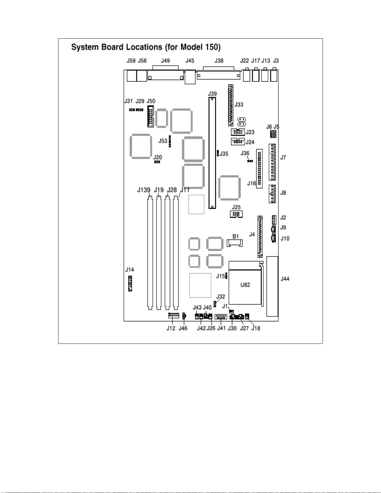
.
Figure 19. RS/6000 43P 7043 Model 150 - System Board Locations
Detailed Product Descriptions 51
Page 70

Table 5. RS/6000 43P 7043 Model 150 - System Board Components Location
Location Description Location Description
B1 Battery connector J27, J30 System fan connector
J2 5x5 Auxiliary 5v connector J28 Memory connector #2
J3 Audio input co nnector J32 Privileged-access password
jumper
J4 Internal SCSI Conn. #2 J33 Internal SCSI 16-bit conn.
J5 CD-ROM connector J35, J36 SCSI security jumper
J6 CD-ROM audio connector J38 External SCSI jumper
J7, J8 Power connector J39 Riser card connector
J10 Media fan connector J40 Power switch connector
J11 Memory connector J41 Op panel connector
J13 Audio output connector J42 Power indicator LED conn.
J15 Remote power-up jumper J43 HDD activity LED connector
J16 Diskette drive connect or J44 Voltage regulator connector
J17 Microphone jack J45 Ethernet twisted pair conn.
J18 Reset connector J46 Internal speaker connector
J19 Memory connector #3 J49 Parallel port connector
J20 Power-on password
jumper
J22 Headphone jack J53 Ethernet EPROM connector
J23 Serial port connector #2 J56 Mouse port connector
J24 Serial port connector #1 J59 Keyboard connector
J25 Table port connector J139 Memory connector #4
J26 CPU fansink connector
3.1.1.3 Memory Subsystem
The Model 150 comes standard with a 128 MB of ECC SDRAM memory. It
supports four industry standard DIMM sockets and can support up to 1 GB of
system memory. Memory DIMM size includes 64 MB, 128 MB, or 256 MB.
The memory DIMMs can be populated in any order.
52 RS/6000 43P 7043 Models 150 an d 260 Ha ndb ook
J50 Ethernet AUI
Page 71
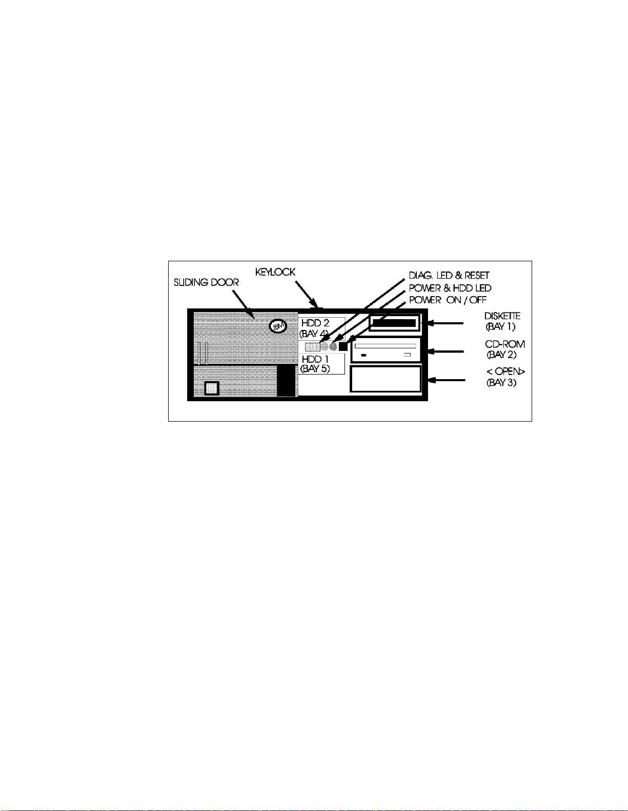
3.1.1.4 Bays
The system contains five bays, three of which accommodate the following
standard devices:
• 3.5-inch diskette drive bay
It accommodates the standard 1.44 MB diskette drive.
• 5.25-inch CD-ROM drive bay
It accommodates the standard 32X CD-ROM drive with the convenience
of loading a CD without a caddy.
• 5.25-inch disk drive bay.
It accommodates the standard 4.5 GB Ultra SCSI disk drive that can be
upgraded in the initial machine order to 9.1 GB Ultra SCSI disk. For more
detailed information about the disk drives see Table 29 on page 121.
Figure 20. RS/6000 43P 7043 Model 150 - Front View
The empty bays can accommodate a second CD-ROM, tape drive or other
media device. A 4.5 GB (# 2900) or 9.1 GB (# 2908) hard disk can be
installed in bay 3 with a mounting kit (# 6509).
3.1.1.5 Internal CD-R OM Drive
The 32X SCSI-2 Internal CD-ROM Drive is a tray loading CD-ROM drive
providing up to 4800 KB/s maximum media data transfer rate. It is a 5.25 inch
half-high form factor, single ended, 8 bit, multi-session capable, CD-ROM
drive that provides state-of-the-art performance and supports existing 600
MB CD-ROM discs. It supports either the standard 12 cm or the smaller 8 cm
CD-ROM disk.
Detailed Product Descriptions 53
Page 72

For more detailed technical information about the CD-ROM drive, refer to
Table 30 on page 122.
3.1.1.6 Stand ard I/O Ports
The system provides the following standard I/O ports:
Keyboard port The optional Quiet Touch Keyboard may plug into this
port.
Mouse port A port is provided to support an optional three-button
mouse.
Ta blet port If required, a tablet can be connected.
Serial port Two 9-pin D-shell serial connectors are available for
external RS232 access.
Parallel port One 25-pi n parallel port is provided that maintains
complete compatibility with machines containing ISA,
EISA, and Micro Channel parallel ports.
3.1.1.7 PCI Adapter Slots
The Model 150 contains five 32-bit PCI slots. Following is a brief description
according to their slots number.
• Slots 1 and 5 are short slots
• Slots 2, 3, and 4 are long slots
• Slots 2, and 3 are connected to the primary PCI bus on the planar
• Slots 1, 4, and 5 are on the secondary PCI bus provided by the bridge chip
on the riser card.
Thick Connector Twisted-Pair Connector
Figure 21. RS/6000 43P 7043 Model 150 - Rear View
54 RS/6000 43P 7043 Models 150 an d 260 Ha ndb ook
Page 73

3.1.1.8 Integ rated E thernet A dapter
An integrated 10/100 Mbps Ethernet AUI/RJ45 port (10Base5/100BaseT) is
part of the base system.
3.1.1.9 Integ rated Ul tra SCS I Controll er
The Model 150 has an integrated Ultra SCSI controller, which is operated at a
speed of 40 MB/s.
3.1.1.10 AIX O perating System
The RS/6000 Model 150 includes one to two user license, for a full-function
AIX Version 4.2.1 or Version 4.3.2 package at no additional charge.
3.1.1.11 Year2000 and EuroReady
The IBM RS/6000 43P 7043 Model 150 is Year 2000 ready. Please refer also
to 1.8, “Year 2000” on page 18 for details.
When used with AIX 4.3.2, this product is EuroReady.
3.1.1.12 Public ations
The following publications will be shipped with the Model 150.
Table 6. Publications Shipped with the Model 150
Order Number Title
SA38-0510 7043 43P Series Setup Instructions
SA38-0511 7043 43P Series Users Guide
SA23-2690 (USA customers only) Customer Support Information
SA23-2652 System Unit Safety Information
SA38-0538 PCI Adapter Placement Reference Guide
Customer Installable Options Libra ry CD-ROM
Warranty Booklet (USA customers only)
1
The CD-ROM is not orderable, it is shipped only at manufacturing. No form
1
number is available.
Only the ship-pack publications appear in the sales manual. A complete list of
publications is provided in the PUBS section of HONE.
Detailed Product Descriptions 55
Page 74

3.1.2 Reliability, Availability, and Serviceability (RAS)
Following are the features that provide the IBM R S/6000 Model 150 reliability,
availability, and serviceability.
3.1.2.1 Reliabilit y, Fault Tolerance, and Data Integri ty
The reliability of the Model 150 system starts with reliable components,
devices, and subsystems. During the design and the development process,
subsystems go through rigorous verification and integration testing
processes. During system manufacturing, systems go through a testing
process to ensure the highest product quality level.
The Model 150 system memory offers ECC (Error-Checking and Correcting)
fault-tolerant features. ECC corrects environment-induced single-bit
intermittent memory failures. As well as single hard failures. With ECC, the
majority of memory failures will not impact system operation. ECC also
provides double-bit memory error detection which protects data integrity in
the event of the double-bit memory failures. The system bus and PCI buses
are designed with parity error detection.
Disk mirroring and disk controller duplexing capability are provided by the AIX
operating system.
The journaled file system (JFS) of AIX operating system maintains file system
consistency and prevents data loss when the system is abnormally halted
due to a power failures.
An available RAID hardware feature external to the system provides data
integrity and fault tolerance in the event of the disk failure.
3.1.2.2 Fault Monitoring Functions
Following are the functions used to monitor faults during the boot process.
• POST (Power-on-Self Test) that checks the processor, L2 cache, memory
and associated hardware that are required for proper booting of the
operating system every time the system is powered on. If a non-critical
error is detected, or if the error(s) occur in the resources that can be
removed from the system configuration, the booting process will proceed
to completion. The error(s) are logged in the system Non Volatile RAM.
• Disk drive fault tracking is a facility that can alert the system administrator
of an impending disk failure before it impacts customer operation.
• AIX log facility where hardware and software failures are recorded and
analyzed (by the Error Log Analysis routine) to provide warning to the
system administrator on the causes of system problems. This also
56 RS/6000 43P 7043 Models 150 an d 260 Ha ndb ook
Page 75

enables IBM service representatives to bring along needed replacement
hardware components during a service, thus minimize system repair time.
3.1.2.3 Environment Monitoring Functions
Following is a list of the provided environment monitoring functions.
• Fan speed monitoring to provide warning and orderly system shutdown
when the speed is out of operational specification.
• AC power loss sensing to provide orderly system shutdown.
3.1.2.4 Error Handling and Reporting
In an unlikely event of system hardware or environmental induced failure, the
system Run-Time Error Capture capability will systematically analyze the
hardware error signature to determine the cause(s) of failure. The analysis
result will be stored in system Non Volatile RAM (NVRAM). When the system
can be successfully rebooted either manually or automatically, the error will
be automatically reported to AIX operating system. The Error Log Analysis
(ELA) can be used to display the failure cause and the physical location of
failure hardware.
3.1.2.5 Availability Enhancement Functions
On-line (concurrent) Diagnostics with Error Log Analysis and Service Aids
allow administrators or IBM service representatives to diagnose potential
system malfunction without interrupting end-user operation.
The auto-restart (reboot) option, when enabled, automatically reboots the
system following an unrecoverable software error or hardware failure.
3.1.2.6 Serviceability
The Model 150 is designed for customer setup of the machine and for
subsequent addition of most features (adapters/devices). The Model 150
supports personnel to remotely log into a system to review error logs and
perform remote maintenance.
The diagnostics consists of Stand-Alone Diagnostics (system dedicated to
service) and on-line diagnostics. On-line diagnostics, when installed, are
resident with AIX on the disk or system. They can be booted in single user
mode (service mode), run in maintenance mode, or run concurrently
(concurrent mode) with other applications. They have access to the AIX Error
Log and the AIX configuration data.
Service Mode allows checking of system devices and features.
Detailed Product Descriptions 57
Page 76

Concurrent Mode allows the normal system functions to continue while
selected resources are being checked.
Maintenance Mode allows checking of most system resources.
The System Management Service (SMS) error log is accessible from the
SMS menu for tests performed through SMS programs.
3.1.2.7 Service Director for RS/6 000
The Service Director for RS/6000 is available at no additional charge if the
RS/6000 processor is covered by an IBM Warranty or IBM Maintenance
Service Agreement. When installed on the RS/6000, the Service Director for
RS/6000 can enhance IBM’s ability to provide the system with maintenance
service. The Service Director for RS/6000 is responsible for the following
operations:
• Monitors and analyzes system errors, and if needed, can automatically
place a service call to IBM without customer intervention.
• Can reduce the effect of business disruptions due to unplanned system
outages and failures.
• Performs problem analysis on a subset of hardware-related problems and,
with customer authorization, can automatically report the results to IBM
service.
3.1.2.8 On-line Customer Support (OCS)
On-line Customer Support for hardware problem reporting may be performed
through remote login by RS/6000 specialists using normal AIX facilities. The
Service Director for RS/6000 software can also be used for this capability.
AIX support offerings will be under AIXSERV and Service Director for
RS/6000.
3.1.3 Supported Op tional Features
In this section,
external adapters, and external subsystems that can be configured on the
RS/6000 Model 150.
3.1.3.1 Mem ory
RS/6000 Model 150 comes standard with 128 MB of ECC SDRAM memory.
The Model 150 can expanded up to 1 GB of memory. This allows the
customer to easily upgrade the processor cards by selecting one to four
58 RS/6000 43P 7043 Models 150 an d 260 Ha ndb ook
optional features
are defined as internal optional devices,
Page 77
memory DIMMs (64 MB, 128 MB, and 256 MB). The available memory
specifications are shown in Table 7.
Table 7. Optional Memory for Model 150
Memory Density (SDRAM DIMM) 256 MB 128 MB 64 MB
Feature Code # 4169 # 4150 # 4149
Average Seek Time 10 ns 10 ns 10 ns
Number of PINs 168 168 168
Type Buffered
SDRAM
Note
Buffered
SDRAM
Buffered
SDRAM
The DIMMs do not have to be installed in pairs.
3.1.3.2 Internal Disk Drives
Three internal Ultra SCSI disks drives can be accommodated in the internal
bays of the system. For more detailed information about the disk drives see
Table 29 on page 121.
3.1.3.3 Internal CD-R OM Drive
One additional 32X CD-ROM drive can be added to the system (# 2624) into
media bay 3. For this the Media Bay Disk Drive Mounting Kit (# 6509) is
required. You can find more detailed technical information about the CD-ROM
drive in Table 30 on page 122.
3.1.3.4 Intern al Tape Drive
One 12 / 24 GB 4 mm internal tape drives can be installed in the internal bay
of the system. For detailed information about the internal tape drives, refer to
the Table 31 on page 122.
3.1.3.5 Keyboard
1
New Stealth Black Quiet Touc h Keyboards (# 87xx
) are available in 37
languages. They have the same quiet and soft touch as the Pearl White Quiet
1
Touch Key boards (# 66xx
). Like their predecessors, these keyboards have
removable wrist rests for added comfort, and a 3-meter cable for added
flexibility.
1
xx depends on the country)
(
Detailed Product Descriptions 59
Page 78

The present Pearl White Quiet Touch Keyboards will also continue to be
available with black systems giving users maximum flexibility in choosing
their desktop color scheme.
There is Euro currency symbol support on appropriate national language
versions.
3.1.3.6 Mouse
A Stealth Black 3-Button (# 8741) mouse is available. The new mouse has a
3-meter cable with a standard 6-pin mini-DIN connector providing the
flexibility users want. It is also still available in pearl white (# 6041).
3.1.3.7 Graphi cs Adapter s
For 2D graphics applications the Model 150 offers the POWER GXT120P,
GXT250P, and GXT255P accelerator cards. The GXT120P meet the graphics
needs for many commercial applications and provides an entry point for
workstation users. It is also a good price/performance choice for server
environments.
For advanced graphics functions, the GXT3000P graphics accelerator for 3D
visualization marks a breakthrough in performance and functionality for
design and visualization solutions.
Refer to 3.1.4, “RS/6000 43P 7043 Model 150 Adapter Placement
Guidelines” on page 66 or to 5.2, “Graphics Adapters” on page 135 for more
information.
Note
GXT3000P requires AIX 4.3.2. Support for AIX 4.2.1 is planned for a later
date.
3.1.3.8 Graph ic Peri pheral De vices
The following graphic peripheral devices are officially supported:
• 6093-011 CursorPad Tablet
• 6093-012 Large Tablet
• 6093-021 IBM Tablet Model 021
• 6094-010 Dials
• 6094-020 Lightened Programming Function Keyboard (LPFK)
• 6094-030 Spaceball
• 6094-031 Spaceball
60 RS/6000 43P 7043 Models 150 an d 260 Ha ndb ook
Page 79

• 6094-040 Spaceball
• 6094-600 Magellan Enhanced Input Device
3.1.3.9 Monit ors
The IBM P72, P92, and P202 color monitors are the premium graphics
monitors for RS/6000 workstations. These monitors are for customers who
demand image accuracy in a large screen format combined with
performance, quality, reliability, and connectivity.
Table 8. List of Orderable Monitors for Model 150
Description Feature
Code
P72 Color Monitor, Stealth Black # 3623 17.0
P72 Color Monitor, Pearl White # 3620 17.0
P92 Color Monitor, Stealth Black # 3625 19.0
P92 Color monitor, Pearl White # 3621 19.0
P202 Color Monitor, Stealth Black # 3626 21.0
P202 Color Monitor, Pearl White # 3622 21.0
Screen Size
(in inches)
3.1.3.10 Personal Microphone
The IBM personal microphone (# 6308) is a lightweight microphone and
headset that conveniently mounts over and behind the user’s ear. The
microphone element is attached to the earpiece with a thin tubular boom. The
IBM personal microphone allows adjustments to be made to position the
microphone and headset for either the left or right ear.
The IBM personal microphone is suitable for a wide range of applications, but
is especially suited for speech recognition applications including dictation and
navigation in an office environment. The microphone allows consistent
performance by providing for an optimum distance between the voice s ource
and the microphone element and by providing concurrent feedback to the
user through the personal headset.
3.1.3.11 Software Pre-Install
Licensed programs may be pre-installed on the media selected. To order this
option, specify code (# 5005) on the initial system order. The pre-installed
licensed programs will be at the same release level as programs being
shipped from the program libraries at the time the system is manufactured.
Detailed Product Descriptions 61
Page 80

3.1.3.12 PCI Storage Adapters
The following PCI SCSI adapters are supported in the Model 150
• PCI Single-Ended Ultra SCSI Adapter
• PCI Differential Ultra SCSI Adapter
• Serial Storage Architecture (SSA)
PCI Single-Ended Ultra SCSI Adapter (# 6206)
The PCI Single-Ended Ultra SCSI has a maximum data transfer rate of 40
MB/s which is two times the maximum data transfer rate of Fast/Wide
adapters and requires one PCI slot
PCI SCSI-2 Differential Ultra SCSI Adapter (# 6207)
The PCI Differential Ultra SCSI adapter is the next generation of SCSI-2
performance with a maximum data transfer rate of 40 MB/s and occupies one
PCI slot.
PCI SSA Multi-Initiator/RAID EL Adapter (# 6215)
The PCI SSA Multi-Initiator/RAID EL adapter allows up to eight RS/6000 to
attach to an SSA loop in non-RAID mode and two RS/6000 to attach in
RAID-5 mode and requires one PCI slot.
You can find more detailed information about the PCI storage adapters in 4.8,
“PCI Storage Adapters” on page 124.
3.1.3.13 Commun ications Adap ters
The following communications adapters are officially supported in Model 150.
• IBM PCI Token-Ring adapter (# 2920)
• IBM PCI 10/100 Mbps Ethernet adapter (# 2968)
• ATM adapters
• Turboways 155 UTP PCI ATM Adapter (# 2963)
• Turboways 155 MMF PCI ATM Adapter (# 2988)
• Turboways 25 ATM PCI ATM Adapter (# 2998)
• FDDI adapters
• SysKonnect SK-NET FDDI-LP SAS PCI Adapter (# 2741)
• SysKonnect SK-NET FDDI-LP DAS PCI Adapter (# 2742)
• SysKonnect SK-NET FDDI-UP SAS PCI Adapter (# 2743)
• Asynchronous adapters
• PCI 8-Port Asynchronous Adapter EIA-232/RS-422 (# 2943)
• PCI 128-Port Asynchronous Controller (# 2944)
62 RS/6000 43P 7043 Models 150 an d 260 Ha ndb ook
Page 81

• 2-Port Multiprotocol PCI Adapter (# 2962)
• Eicon ISDN DIVA PRO 2.0 PCI S/T Adapter (# 2708)
3.1.3.14 Supported Devices
The following is a list of the external subsystems that are officially supported
by the RS/6000 Model 150.
External Disk Subsystems
• 7131-105 Multi-Storage Tower
• 7131-405 SSA Multi-Storage Tower
• 7133-010 SSA Disk Subsystem (Rack-Mounted)
• 7133-020 SSA Disk Subsystem (Rack-Mounted)
• 7133-500 SSA Disk Subsystem
• 7133-600 SSA Disk Subsystem
• 7137-412 Disk Array Subsystem (1.97 - 6.91 GB)
• 7137-413 Disk Array Subsystem (3.94 - 13.77 GB)
• 7137-414 Disk Array Subsystem (8.39 - 29.36 GB)
• 7137-415 Disk Array Subsystem (17.7 - 70.83 GB)
• 7203-001 Portable Disk Drive
• 7204-010 1 GB Disk Drive
• 7204-112 1.1 GB Fast/Wide Disk Drive
• 7204-113 2.2 GB Fast/Wide Disk Drive
• 7204-114 4.5 GB Fast/Wide Disk Drive
• 7204-118 18 GB SE External Disk Drive
• 7204-139 9.1 GB Fast/Wide Disk Drive
• 7204-215 2 GB Differential Disk Drive
• 7204-315 2 GB Differential Fast/Wide Disk Drive
• 7204-317 2.2 GB Differential Fast/Wide Disk Drive
• 7204-325 4.5 GB Differential Fast/Wide Disk Drive
• 7204-339 9.1 GB External Disk Drive
• 7204-402 External 2.2 GB Disk Drive
• 7204-404 External 4.5 GB Disk Drive
• 7204-418 18 GB DE External Disk Drive
Detailed Product Descriptions 63
Page 82

External SCSI Devices
• 3995-C60 Optical Library Dataserver ( 1 Dr ive)
• 3995-C62 Optical Library Dataserver ( 2 Dr ives)
• 3995-C64 Optical Library Dataserver ( 2 Dr ives)
• 3995-C66 Optical Library Dataserver ( 4 Dr ives)
• 3995-C68 Optical Library Dataserver ( 4 Dr ives)
• 7209-002 Optical Disk Drive
• 7209-003 Optical Disk Drive
• 7210-005 CD-ROM Drive
• 7210-010 CD-ROM Drive (Quad speed)
• 7210-015 CD-ROM Drive (8x speed)
Tape Drive Subsystems
• 3490-F00 IBM Magnetic Tape Subsystem
• 3490-F01 IBM Magnetic Tape Subsystem
• 3494-L12 Tape Library Dataserver
• 3570-B00 IBM Magstar MP Tape Subsystem
• 3570-B01 IBM Magstar MP Tape Subsystem (Floor Library, 1 Drive)
• 3570-B02 Tape Subsystem (2 Drives)
• 3570-B11 IBM Magstar MP Tape Subsystem (Rack Mounted, 1 Drive)
• 3570-B12 IBM Magstar MP Tape Subsystem (Rack Mounted, 2 Drives)
• 3570-B1A IBM Magstar MP Tape Drive Model B1A
• 3570-C00 Magstar Magnetic Tape Subs * 1 Tape Lib (1), SCSI
• 3570-C01 Magstar Magnetic Tape Subs * 1 Tape Lib (20), SCSI
• 3570-C02 Magstar Magnetic Tape Subs * 2 Tape Lib (20), SCSI
• 3570-C11 Magstar Magnetic Tape Subs * 1 Tape Lib (20), SCSI
• 3570-C12 Magstar Magnetic Tape Subs * 2 Tape Lib (20), SCSI
• 3575-L06 IBM Magstar MP Tape Libr ary DataServer - 60 Cartridge
• 3575-L12 IBM Magstar MP Tape Libr ary DataServer - 120 Cartridge
• 3575-L18 IBM Magstar MP Tape Libr ary DataServer - 180 Cartridge
• 3575-L24 IBM Magstar MP Tape Libr ary DataServer - 240 Cartridge
• 3575-L32 IBM Magstar MP Tape Libr ary DataServer - 320 Cartridge
64 RS/6000 43P 7043 Models 150 an d 260 Ha ndb ook
Page 83

• 3590-B11 High Performance Tape Subsystem
• 3590-B1A High Performance Tape Subsystem
• 3590-C12 Silo Compatible Tape Subsystem
• 7205-311 DLT Tape Drive Bridge Box
• 7206-005 4 GB 4mm Tape Drive
• 7206-110 Cartridge Autoloader 4mm, DDS-3, SCSI-2, DAT
• 7207-011 525 MB 1/4" Tape Dr ive
• 7207-012 1.2 GB 1/4" Tape Drive
• 7207-122 4 GB External SLR5 QIC Tape Drive
• 7207-315 13 GB 1/4" Tape Drive
• 7208-011 5 GB 8mm Tape Drive
• 7208-341 20 GB External 8mm Tape Drive
• 7331-205 8mm Tape Library
• 7331-305 8mm Tape Library
• 7332-005 4mm DDS-2 Tape Autoloader
• 7332-310 4mm Tape Autoloader
• 7336-205 4mm Tape Library
• 7337-305 Digital Linear Tape Subs ystem
• 7337-306 Digital Linear Tape Subs ystem
• 9348-012 1/2" 9-Track Magnetic Tape Unit
Communications Subsystems
• 7318 Model P10 Serial Communication Network Server
• 7318 Model S20 Serial Communication Network Server
Printers, Plotters and ASCII Terminals
These devices are all supported through standard ports. Refer to the list of
supported devices in the appropriate section of the AIX sales manual pages.
Modems
• IBM 5841, 5853, 5865
• Hayes compatible
• Recal-Vadic compatible
Detailed Product Descriptions 65
Page 84

3.1.4 RS/6000 43 P 7043 Model 15 0 Adapter Pla cement Guide lines
This machine is designed for customers to install adapters.Use the following
table to identify specific slot location options for the following adapters in your
7043 Model 150 system.
When determining a slot in which to place a new adapter, you should start
from the top of Table 9. The list of slot numbers represent the order in which
the slots should be used.
Table 9. Adapter Placement Guidelines for Model 150
Adapter Feature
Code
Ultimedia Video Capture 2639 1 Any Slot
Eicon ISDN DIVA PRO 2.0 PCI S/T Adapter 2708 1 Any Slot
2
PCI SysKonnect SK-NET FDDI-LP SAS
PCI SysKonnect SK-NET FDDI-LP DAS
PCI SysKonnect SK-NET FDDI-UP SAS
POWER GXT3000P 2825 1 Slot 3
POWER GXT120P
1
2741 2 Any Slot
2
2742 2 Any Slot
2
2743 2 Any Slot
2838 4 Any Slot
max.
Quan
tity
Slot Usage
POWER GXT550P 2845 1 Slot 2, 3
POWER GXT255P
PCI Token Ring Adapter 2920 4 Any Slot
PCI 8-Port Asynchronous EIZ-232/RS-422A 2943 2 Any Slot
PCI 128-Port Asynchronous Controller 2944 2 Any Slot
PCI 2-Port Multiprotocol 2962 2 Slots 5, 4, 1
PCI 155 TURBOWAYS ATM UTP 2963 2 Any Slot
PCI 10/100 Mbps Ethernet Tx 2968 4 Any Slot
PCI 155 TURBOWAYS ATM MMF 2988 2 Any Slot
PCI 25 TURBOWAYS ATM 2 998 4 Any Slot
PCI Single-Ended Ultra SCSI 6206 2 Any Slot
PCI Differential Ultra SCSI 6207 2 Any Slot
PCI SSA Multi-Initiator/RAID EL 6215 1 Slots 2, 3
1
66 RS/6000 43P 7043 Models 150 an d 260 Ha ndb ook
2852 4 Any Slot
Page 85

1
If both the POWER GXT120P and the POWER GXT255P are installed, the
POWER GXT255P must be installed in slot 2 or 3.
2
If two SysKonnect SK-NET FDDI PCI adapters are installed, they cannot be
installed in slots next to each other.
3.1.5 Service Package
Service package kit (# 3752) contains service publications, wrap plugs, and
diagnostic CD-ROM. It also includes Maintenance Analysis Procedures
(MAPs) that are not common to other RS/6000 systems. The
Information for Multiple Bus Systems,
common to all multiple bus units and is used primarily for problem isolation by
a customer’s service specialist trained on the unit being serviced.
These publications are intended to be used in the customer’s enterprise by
the customer’s own service specialists, and not by IBM Service personnel.
Two wrap plugs are included for use in diagnostic testing of the following
connections to the system units:
• RS-232 serial I/O port
• Parallel I/O port
This kit also contains a system diagnostic CD-ROM, along with a test diskette
for use by the customer service specialist (not by IBM service personnel).
Diagnostics
SA38-0509 contains information
3.1.5.1 Options Library (Hard Copy)
A hard copy version of the options publications (# 3753) can be obtained.
This hard copy is also available through PUBORDER (
Library English,
SK2T-7452).
CIO - Option Pubs
Detailed Product Descriptions 67
Page 86

3.2 RS/6000 43P 7043 Model 260 Prod uct Description
The IBM RS/6000 43P 7043 Model 260 is a new addition to the RS/6000
workstation and workgroup server family. The Model 260 is an affordable
64-bit symmetric multiprocessing (SMP) system with true multi-threaded
application support and extended floating-point capabilities. This is IBM’s first
announced 64-bit workstation and workgroup server. With the new
GXT3000P graphics adapter, it provides significant performance
enhancements over the Model 150 and the Model 240.
Figure 22. RS/6000 43P 7043 Model 260 (with Peripherals, and Spaceball)
The Model 260 is a 1- or 2-way SMP system utilizing the 64-bit 200 MHz
POWER3 processor with 4 MB of Level 2 (L2) cache per processor. The
system memory can be expanded up to 4 GB. Ethernet, Ultra SCSI, and a
service processor are integrated within the Model 260. The Model 260 also
contains five PCI slots and five bays. Two of the slots are 64-bit slots and
three are 32-bit slots. A 1.44 MB 3.5-inch diskette drive and a 32X maximum
speed CD-ROM occupy two of the bays. A variety of 2D and 3D graphics
adapters, including a new advanced 3D graphics adapter, are available for
the Model 260. This graphics capability, along with excellent price and
68 RS/6000 43P 7043 Models 150 an d 260 Ha ndb ook
Page 87

performance, position the Model 260 as a single-seat MCAD design and
analysis solution.
In addition, the Model 260’s SMP capability and robust set of disk drive and
communications features make it an excellent entry technical and commercial
server. It is the lowest cost 64-bit SMP server in the RS/6000 family of
products. The AIX Version 4.2.1 or 4.3.2 operating system is included with
each system and can be pre-installed, if desired.
The Model 260 is designed for use as a mid- to high-range graphics
workstation, or as an entry server. It supports MCAD, CAE, Geophysical, and
entry technical server customers. It is also well suited for use as an entry
SMP/64-bit server for ISVs and customers who want a cost-effective
development platform for developing and testing applications that will run on
larger RS/6000 systems. The dual processing power of the Model 260 and its
small package make it an excellent solution for Internet service providers and
customers that need or want a stand-alone internet server.
The system is designed for customer setup of the machine and for
subsequent addition of most features (adapters/devices).
3.2.1 Model 260 Syst em Architecture
The RS/6000 43P 7043 Model 260 is the first product of the RS/6000 family
based on the POWER3 architecture. The design incorporates high-speed
processor and memory buses, a more efficient 4 MB Level 2 (L2) cache
design, a high-performance memory-I/O controller, and fast Synchronous
Dynamic Random Access Memory (SDRAM).
For more information about the POWER3 Architecture refer to 2.4.1, “The
POWER3 Microprocessor” on page 35.
3.2.2 Standard Features
In this section, the standard features of the Model 260 and their most
important characteristics are described.
3.2.2.1 Processor Subsystem
The PCI-based RS/6000 43P 7043 Model 260 features the POWER3 64-bit
microprocessor at 200 MHz. The processor includes an L1 cache split into 32
KB instruction and a 64 KB data cache. Each processor has 4 MB of Level 2
(L2) cache. Systems with only one processor mus t have i nstalled the CPU
card in slot 1.
Detailed Product Descriptions 69
Page 88

The processor subsystem is implemented on pluggable cards. T wo processor
card slots are available. If two processor cards are installed in the system,
they must both be the same type or the system will not power on.
3.2.2.2 System Planar Bo ard
One planar is installed in a Model 260. It provides the system bus and card
connections for the riser card, a voltage regulator, and clock module and four
memory DIMM slots. Power supply connections, I/O connections, and a
pin-grid array socket for the PowerPC processor.
One or two 200 MHz POWER3 processors can be installed.
Figure 23 shows the location of the I/O board components, Table 10 lists their
attributes.
70 RS/6000 43P 7043 Models 150 an d 260 Ha ndb ook
Page 89

Processor Card
(primary)
Processor
Card
Memory
Cards
Figure 23. RS/6000 43P 7043 Model 260 - System Planar & I/O Board
Table 10. RS/6000 43P 7043 Model 260 - System Planar & I/O Board Components
Location Description Location Description
J1 Operator panel power
connector
J2 Operator panel audio
connector
Detailed Product Descriptions 71
Page 90

Location Description Location Description
J3 PCI fan connector J4 I/O board connector to
system board
J5 VPD module connector J6 ESP external connector
J7 Internal SCSI connector J8, J9 64-bit PCI connectors
J10 CD ROM Audio J11 Battery connector
J12, J13, J14 32-bit PCI connectors J15 Service processor
external connector
J16 Power connector J17 Diskette drive connector
J18 T abl et connector J19 Power connector
J20 AUI Ethernet connector J21 Cec fan connector
J23 Serial port connector J24 Keyboard/Mouse
connector
J25 RJ45 Ethernet connector J26 Audio in/out
J27 Parallel port connector J28 External SCSI connector
3.2.2.3 Memory Subsystem
The base configuration comes with 256 MB Error Checking and Correcting
(ECC) SDRAM (2 x 128 MB DIMMs).
The Model 260 has an enhanced memory controller running at 100 MHz
memory bus speed. See 3.1.3.1, “Memory” on page 58 for more information
how the memory can be expanded.
Synchronous DRAM
The SDRAM operates faster than conventional DRAM. The SDRAM can
supply data every 10 nanosecond clock cycle once its initial access time of 60
nanoseconds has been satisfied. As with conventional memory, the SDRAM
banks have a period of latency after an access. During this period, the
memory bank would be designated as busy. To achieve better performance,
another memory bank (already precharged) needs to be accessed during that
period of latency. The memory I/O controller uses heavy queueing to be able
to make an intelligent decision on which memory bank to access next. The
controller will queue up to eight read commands and eight write commands
and attempts to schedule all reads to non-busy banks. It fills in with writes
when no reads are pending.
72 RS/6000 43P 7043 Models 150 an d 260 Ha ndb ook
Page 91

3.2.2.4 Operator Panel
The operator panel on the front of the Model 260 contains a power-on switch
(on/off), a reset button, a power-on light, a hard disk drive in use light, and an
LCD display for function and diagnostic feedback.
Table 11 lists the operator panel components shown in Figure 24.
Table 11. RS/6000 43P 7043 Model 260 - Operator Panel Components
Number # Description
1 Power- On Sw it c h: Turns computer power on and off.
2 Reset Switch: Resets your syst em unit.
3 Power- On L E D: Glows when computer is on.
4 Hard Disk Drive Status LE D: Glows whe n computer is re ading from
or writing to the disk drive.
5 Operator Panel Display: Displays current status of sy stem uni t startup,
or diagnostic information in the event of a hardware problem.
6 Headset Receptacle: For connecting audio headphones.
7 Microphone Receptac le: For connecting audio microphone.
Figure 24. RS/6000 43P 7043 Model 260 - Operator Panel
Detailed Product Descriptions 73
Page 92
3.2.2.5 Bays
Five bays are available for the system, as shown in Figure 25. One is
reserved for the diskette drive (bay 1) and one for the internal CD-ROM drive
(bay 2).
The Model 260 comes with a standard Ultra-SCSI 16-bit Disk Drive installed
in bay 4. Up to three internal disks can be installed in the system.
Bay 3, a 5.25 inch bay, can accommodate a second CD-ROM, tape drive, or
other disk device. If you want to install a 4.5 GB Ultra SCSI Disk Drive
(# 2900) or a 9.1 GB Ultra SCSI 16-Bit 1-Inch High Disk Drive (# 2908), you
have to use the 5.25 inch Media Bay Mounting Kit (# 6508).
Bays 4 and 5, which are both 3.5 inch bays, can contain a 4.5 GB Ultra SCSI
Disk Drive (# 3028) or 9.1 GB Ultra SCSI Disk Drive (# 3029).
Table 12 lists a summary of the different storage devices and in which bay
they can be installed:
Table 12. Storage Device Features
Feature Code Device Max.
Quantity
2624 600 MB 32X CD-ROM 2 2, 3
2900 4.5 GB Ultra SCSI Disk 1 3
Bay #
2908 9.1 GB Ultra SCSI Disk 1 3
3028 4.5 GB Ultra SCSI Disk 2 4, 5
3029 9.1 GB Ultra SCSI Disk 2 4, 5
6156 8 mm 20/40 GB Tape Drive 1 3
6159 4 mm 12/24 GB Tape Drive 1 3
6508 5 1/4" Media Bay Mounting Kit 1 3
For more detailed information about the disk drives, see Table 29 on page
121.
Note
The Model 260 cannot boot from drives connected to SCSI external
connector.
74 RS/6000 43P 7043 Models 150 an d 260 Ha ndb ook
Page 93
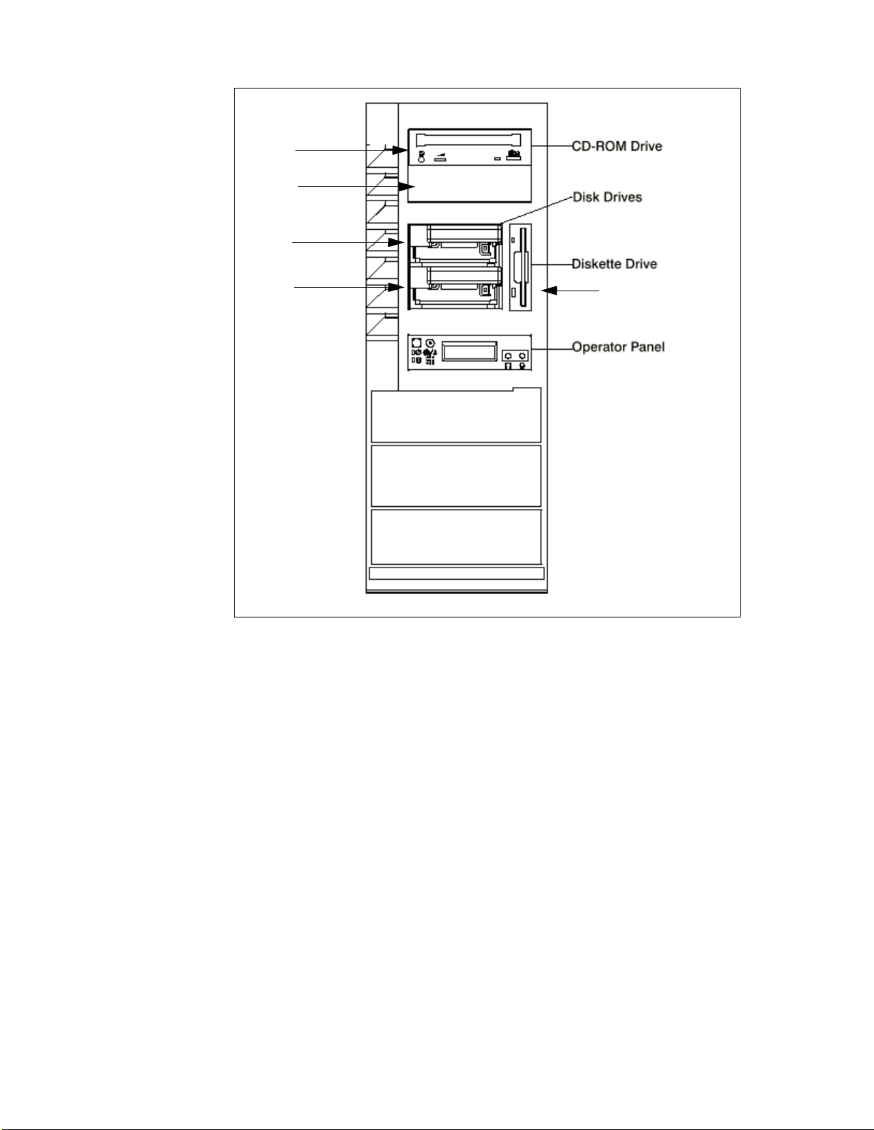
Bay 2
Bay 3
Bay 4
Bay 5
Figure 25. RS/6000 43P 7043 Model 260 - Front View
Bay 1
3.2.2.6 Internal CD-R OM Drive
The 32X SCSI-2 Internal CD-ROM Drive is a tray-loading CD-ROM drive
providing up to 4800 KB/s maximum media data transfer rate. It is a 5.25
inch, half-high form factor, single ended, 8 bit, multi-session capable,
CD-ROM drive that provides state-of-the-art performance and supports
existing 600 MB CD-ROM discs. It supports either the standard 12 cm or the
smaller 8 cm CD-ROM disk.
For more detailed technical information about the CD-ROM drive, refer to
Table 30 on page 122.
Detailed Product Descriptions 75
Page 94

3.2.2.7 Rear Bulkhead Connections and Components
Table 13 lists the connections and components found on the rear bulkhead as
shown in Figure 26.
Table 13. RS/6000 43P 7043 Model 260 - Rear View Components
Number # Description N umber # Description
1 Power Supply LED 2 Power Supply Test Switch
3 Power Connector 4 Serial Connector S1
5 Serial Connector S2 6 AUI Ethernet Connector
7 Tablet Connector 8 Keyboard Conne cto r
9 Mouse Connector 10 Audi o Line Out
11 Audio Line In 12 RJ45 Ethernet Connector
13 Parallel Connector 14 External SCSI Connector
15 PCI Slot 5 (32-bit) 16 PCI Slot 4(32-bit)
17 PCI Slot 3 (32-bit) 18 PCI Slot 2 (64-bit)
19 PCI Slot 2 (64-bit)
3.2.2.8 Stand ard I/O Ports
The system provides the following standard I/O ports:
Keyboard port The quiet touch keyboard, an optional feature, can be
plugged into this standard 6-pin mini-DIN port.
Mouse port A port is provided to support an optional three-button
mouse.
Serial port Two serial ports are provided for a TTY terminal, Modem
and other serial devices.
Parallel port One paral lel port is provided.
3.2.2.9 PCI Adapter Slots
There are five PCI slots in the Model 260:
• Slots 1 and 2 are 64-bit and run at 50 MHz.
• Slots 3, 4 and 5 are 32-bit and run at 33 MHz.
• All slots are long slots.
76 RS/6000 43P 7043 Models 150 an d 260 Ha ndb ook
Page 95

Figure 26. RS/6000 43P 7043 Model 260 - Rear View
3.2.2.10 Integrated Ethernet Adapter
An integrated 10/100 Mbps Ethernet AUI/RJ45 port (10Base5/100BaseT) is
part of the base system.
Detailed Product Descriptions 77
Page 96

3.2.2.11 Integrated Ult ra SCSI Controll er
The Model 260 has two integrated Ultra SCSI controllers. One for internal and
one for external connections. Both are operated at a speed of 40 MB/s.
3.2.2.12 AIX O perating System
The RS/6000 43P 7043 Model 260 includes a one to two user, full-function
AIX Version 4.2.1 or 4.3.2 package at no additional charge.
3.2.2.13 Year 2000 and EuroRea dy
The RS/6000 43P 7043 Model 260 is Year 2000 ready. Please refer also to
1.8, “Year 2000” on page 18.
When used with AIX 4.3.2, this product is EuroReady.
3.2.2.14 Public ations
Table 14 provides the publications shipped with the Model 260 (additional
copies are available):
Table 14. Publications Shipped with the Model 260
Order Number Title
SA38-0555 7043 Model 260 Hardware Setup
SA38-0553 7043 Model 260 User's Guide
SA23-2690 Customer Support Information (US
SA23-2652 System Unit Safety Information
SA38-0538 PCI Adapter Placement Reference
Table 15 provides the additional publications that are available. To order,
contact your IBM representative.
Table 15. Available Publications for Model 260
Order Number Title
SA38-0554 7043 Model 260 Service Guide
SA38-0509 Diagnostics Information for Multiple
SA38-0516 IBM RS/6000 Adapters, Devices
78 RS/6000 43P 7043 Models 150 an d 260 Ha ndb ook
customers only)
Guide
Bus Systems
and Cables Information for Multiple
Bus Systems
Page 97

3.2.3 Reliability, Availability, and Serviceability (RAS)
The RS/6000 43P 7043 Model 260 integrates key reliability, availability, and
serviceability attributes that are described in the following sections.
3.2.3.1 Reliabilit y, Fault Tolerance, and Data Integri ty
The reliability of the Model 260 system starts with reliable components,
devices, and subsystems. During the design and development process,
subsystems go through rigorous verification and integration testing
processes. During system manufacturing, systems go through a thorough
testing process to ensure the highest product quality level.
The Model 260 system L2 Cache and system memory offers Error Checking
and Correcting (ECC) fault-tolerant features. ECC corrects environmentally
induced single-bit intermittent memory failures, as well as single-bit hard
failures. With ECC, the likelihood of memory failures will be substantially
reduced. ECC also provides double-bit memory error detection that protects
data integrity in the event of a double-bit memory failure. System memory
also provides 4-bit packet error detection that helps protect data integrity in
the event of a DRAM chip failure. The system bus, I/O bus, and PCI buses
are designed with parity error detection.
Disk mirroring and disk controller duplexing capability are also provided by
the AIX operating system.
The Journaled File System of the AIX operating system maintains file system
consistency and reduces the likelihood of data loss when the system is
abnormally halted due to a power failure.
An available RAID hardware feature for the system provides data integrity
and fault tolerance in the event of disk drive failure.
3.2.3.2 Serv ice Proces sor
A service processor is included in the system, providing an immediate means
to diagnose, check status, and sense operational conditions of a remote
system, even when the main processor is inoperable. The service processor
enables firmware and operating system surveillance, several remote power
controls, environmental monitoring, reset and boot features, along with
remote maintenance and diagnostic activities, including console mirroring.
The service processor can place calls to report surveillance failures, critical
environmental faults and critical processing faults.
For more information about the Service Processor please refer to Chapter 7,
“Service Processor” on page 185.
Detailed Product Descriptions 79
Page 98

3.2.3.3 Fault Monitoring Functions
Built-in Self-Tes t (BIST) and Power-on Self-Test (POST) checks processor,
L2 cache, memory and associated hardware, that are required for proper
booting of the operating system every time the system is powered on. If a
non-critical error is detected, or if the error(s) occur in the resources which
can be removed from the system configuration, the booting process will
proceed to completion. The error(s) are logged in the system non-volatile
RAM.
Disk drive fault tracking that can alert the system administrator of potential
disk failure before it impacts customer operation.
The AIX log facility where hardware and software failures are recorded and
analyzed (by Error Log Analysis routine) to provide warning to the system
administrator on the causes of system problems. This also enables IBM
service representatives to bring along needed replacement hardware
components when a service call is placed, thus minimizing system repair
time.
3.2.3.4 Mutu al Survei llance
The service processor can monitor the operation of the firmware during the
boot process, and it can monitor the operating system for loss of control. It
also allows the operating system to monitor for service processor activity. The
service processor can take appropriate action, including calling for service,
when it detects that the firmware or the operating system has lost control.
Likewise, the operating system can request a service processor repair action
if necessary.
3.2.3.5 Environmental Monitoring Functions
The following is a list of the environmental monitoring functions.
• Temperature monitoring that increases the fan speed rotation when
ambient temperature is above the normal operating range
• Temperature monitoring to warn the system administrator of potential
environmental related problems (for example, air conditioning and air
circulation around the system) so that appropriate corrective actions can
be taken before a critical failure threshold is reached, and to provide
orderly system shutdown when operating temperature exceeds the critical
level
• Fan speed monitoring to provide warning and an orderly system shutdown
when the speed is out of operational specification
• DC voltages monitoring to provide warning and an orderly system
shutdown when the voltage(s) are out of operational specification
80 RS/6000 43P 7043 Models 150 an d 260 Ha ndb ook
Page 99

• AC power loss sensing to provide an orderly system shutdown
3.2.3.6 Error Handling and Reporting
In the unlikely event of system hardware or environmentally induced failure,
the system Run-Time Error Capture capability systematically analyzes the
hardware error signature to determine the cause of failure. The analysis
result will be stored in system Non-Volatile RAM (NVRAM). When the system
can be successfully rebooted either manually or automatically, the error will
be reported to the AIX operating system. The Error Log Analysis (ELA) can
be used to display the failure cause and the physical location of failing
hardware.
With the integrated service processor, the system has the ability to
automatically send out an alert through the phone line to a pager, or call for
service in the event of critical system failure.
Environmental and Power Warnings (EPOW) is an option that is implemented
in the Model 260. This option provides environmental conditions of the
system to the user in order to try and minimize damage to the system if limits
are close to being exceeded. This option also indicates failure conditions to
AIX for appropriate action.
3.2.3.7 Availability Enhancement Functions
The following enhancements provide additional system availability function.
• On-line (Concurrent) Diagnostics with Error Log Analysis and Service Aids
that allow administrators or IBM service representatives to diagnose
potential system malfunction without interrupting end-user operation
• Auto-restart (reboot) option, when enabled, to automatically reboot the
system following an unrecoverable software error, software hang,
hardware failure, or environmental-induced (AC power) failure
3.2.3.8 Serviceability
The Model 260 is designed for Customer setup of the machine and for
subsequent addition of most features (adapters/devices). For a fee, IBM
Service can perform the installation.
The Model 260 allows support personnel to remotely log into a system to
review error logs and perform remote maintenance. The Model 260 Service
Processor enables the analysis of a system that will not boot.
The diagnostics consist of Stand-alone Diagnostics (system dedicated to
service) and On-line Diagnostics. On-line Diagnostics, when installed, are
resident with AIX on the disk or system. They can be booted in single user
Detailed Product Descriptions 81
Page 100

mode (service mode), run in maintenance mode, or run concurrently
(concurrent mode) with other applications. They have access to the AIX Error
Log and the AIX Configuration Data.
Service Mode allows checking of system devices and features. Concurrent
Mode allows the normal system functions to continue while selected
resources are being checked. Maintenance Mode allows checking of most
system resources.
The System Management Services (SMS) error log is accessible from the
SMS menu for tests performed through SMS programs. The Service
Processor error log is accessible from the Service Processor menu for results
of Service Processor tests.
3.2.3.9 Service Director for RS/6 000
The Service Director for RS/6000 is available at no additional charge if the
RS/6000 processor is covered by an IBM Warranty or IBM Maintenance
Service Agreement. When installed on the RS/6000, the Service Director for
RS/6000 can enhance IBM’s ability to provide the system with maintenance
service.
The Service Director for RS/6000:
• Monitors and analyzes system errors, and if needed, can automatically
place a service call to IBM without customer intervention
• Can reduce the effect of business disruptions due to unplanned system
outages and failures
• Performs problem analysis on a subset of hardware-related problems and,
with customer authorization, automatically reports the results to IBM
Service
3.2.3.10 On-line Customer Support (OCS)
On-line Customer Support for hardware problem reporting may be performed
by remote login by RS/6000 specialists using normal AIX facilities. The
Service Director for RS/6000 software can also be used for this capability.
AIX Support offerings will be under AIXSERV and Service Director for
RS/6000.
3.2.4 Supported Op tional Features
In this section, optional features are defined as internal optional devices.
Adapters are described in more detail in Chapter 5, “Adapters, Overview and
82 RS/6000 43P 7043 Models 150 an d 260 Ha ndb ook
 Loading...