

Page 1

1483/1483DSV Display Station
Operator’s Manual
P/N 701344-003
Page 2
ELUDEHCSNOISIVER/EUSSI
stnemmoC.oN.veRetaD
esaeleRlaitinI
eussieRetelpmoC
esaeleRXTM107300-44389/70/70
100-443107
200-443107
/5049/31
IBM is a registered trademark of International Business Machines Corporation.
NetView is a registered trademark of International Business Machines Corporation.
Proprinter is a trademark of IBM Corporation.
HP LaserJet Series II is a trademark of Hewlett-Packard Co.
Epson is a trademark of Epson America, Inc.
59/10/90
© Copyright 1998 by MTX Corporation
ii 701344-003
Page 3

This equipment complies with FCC regulations for EMI.
WARNING!
This equipment generates, uses, and can radiate radio
frequency energy, and, if not installed and used in accordance with the manual, may cause interference to radio
communications. It has been tested and found to comply
with the limits for a Class A computing device pursuant to
Subpart J of Part 15 of FCC Rules, which are designed to
provide reasonable protection against such interference
when operated in a commercial environment. Operation
of this equipment in a residential area is likely to cause
interference, in which case users, at their own expense,
will be required to take whatever measures may be necessary to correct the interference.
701344-003 iii
Page 4

Table of Contents
Page
Chapter 1. Introduction ............................................................................................1-1
Standard Features............................................................................................1-1
Chapter 2. Customer Installation .............................................................................2-1
Physical Statistics ...........................................................................................2-1
Environmental Requirements..........................................................................2-1
Inspecting the Packages ..................................................................................2-2
Setting Up the Display Station........................................................................2-3
Installing the Optional Light Pen ....................................................................2-4
Connecting the Display Station to the Host Systems......................................2-4
Setting Up the Display Screen ........................................................................2-5
Color Monitor.............................................................................................2-5
Monochrome Monitor ................................................................................2-5
Conducting the Preliminary Operating T est....................................................2-6
Chapter 3. Setup Menus, Controls, and Indicators...................................................3-1
Display Controls .............................................................................................3-1
Keyboard Operation Modes ............................................................................3-1
Emulation Mode .........................................................................................3-1
Native Mode ...............................................................................................3-2
Keyboard Definition Mode.........................................................................3-2
Keyboard Controls..........................................................................................3-3
Offline Setup Mode ........................................................................................3-4
Offline T est Menu.......................................................................................3-5
User Menus ................................................................................................3-6
Offline Screen Menu ..................................................................................3-6
Offline Cursor Menu ................................................................................3-10
Offline Ke yboard Menu............................................................................3-12
Offline Printer Menu ................................................................................3-15
Offline Miscellaneous Menu ....................................................................3-22
Offline Color Menu ..................................................................................3-24
Online Setup Mode .......................................................................................3-27
Online Screen Menu .................................................................................3-28
Online Cursor Menu .................................................................................3-29
Online Keyboard Menu ............................................................................3-30
Online Printer Menu .................................................................................3-31
Online Miscellaneous Menu.....................................................................3-38
Online Color Menu...................................................................................3-39
Operator Status Row Indicators ....................................................................3-40
System Symbols .......................................................................................3-40
Local Symbols..........................................................................................3-45
Chapter 4. Operating Procedures .............................................................................4-1
Preparing to Operate .......................................................................................4-1
Adjusting the Screen Display..........................................................................4-2
Color Monitor.............................................................................................4-2
Monochrome Monitor ................................................................................4-2
Assigning a Coax Printer ................................................................................4-3
Data Entry Function........................................................................................4-3
701344-003 v
Page 5

Table of Contents
Keyboard Operations ......................................................................................4-4
Keyboard Switch Settings.............................................................................4-15
Display Indicators .........................................................................................4-17
Using the Light Pen to Select Data ...............................................................4-17
Using the Electronic Security Lock ..............................................................4-18
Chapter 5. Entry Assist ............................................................................................5-1
Page
Moving the Cursor......................................................................................4-5
Entering Data Characters and Selecting Modes .........................................4-6
Keystroke Record/Playback........................................................................4-7
Record/Play Security Mode........................................................................4-8
Cursor Select Data Entry ............................................................................4-9
Data Editing Function.................................................................................4-9
Message Transmitting Function................................................................4-10
Print Function ...........................................................................................4-11
Partitioning ...............................................................................................4-14
Extended Select Function .........................................................................4-14
Setting the Keyboard Switches through K ey Sequences...........................4-16
Power -On..................................................................................................4-17
Cursor .......................................................................................................4-17
Entry Assist Functions ....................................................................................5-2
Entering Document Mode ..........................................................................5-2
Format Controls..........................................................................................5-2
Cursor Movement and Editing Functions ...................................................5- 5
Chapter 6. Calculator Operation ..............................................................................6-1
Calculator Mode .............................................................................................6-1
Moving the Calculator on the Screen .........................................................6-1
Jumping Between Calculator Mode and Normal Operation .......................6-2
Decimal Calculator.....................................................................................6-2
Binary Calculator .......................................................................................6-5
Hex Calculator............................................................................................6-6
Hex Mathematical Operations ....................................................................6-7
Chapter 7. Problem Determination and Maintenance ..............................................7-1
Diagnostic Testing Function ...........................................................................7-1
Offline T ests ...............................................................................................7-1
System Manager Menu ...................................................................................7-2
User Defined Data ....................................................................................7-10
Product ID.....................................................................................................7-11
Symptom/Action Chart .................................................................................7-12
Preventi ve Maintenance ................................................................................7-14
Chapter 8. Operating the Split Screen Feature.........................................................8-1
Installation Requirements ...............................................................................8-1
Controllers..................................................................................................8-1
Display Requirements ................................................................................8-1
Other Requirements....................................................................................8-1
vi 701344-003
Page 6

Table of Contents
Page
Operation ........................................................................................................8-2
Entering Split Screen Mode........................................................................8-2
Active and Suspended Screens ...................................................................8-2
Key Assignments........................................................................................8-3
Split Screen Mode Enhancements ..............................................................8-3
W alk Through .............................................................................................8- 9
Screen Print Mode ....................................................................................8-10
Chapter 9. Operating the Dual Screen Feature.........................................................9-1
Installation Requirements ...............................................................................9-1
Controllers..................................................................................................9-1
Display Requirements ................................................................................9-1
Other Requirements....................................................................................9-1
Operation ........................................................................................................9-2
Entering Dual Screen Mode .......................................................................9-2
Active and Suspended Screens ...................................................................9-2
Key Assignments........................................................................................9-3
Dual Screen Mode Enhancements ..............................................................9-3
W alk Through .............................................................................................9- 8
Screen Print Mode ......................................................................................9-8
Appendix A. Printer Information .............................................................................A-1
Supported Character Sets...............................................................................A-1
Switch Settings ..............................................................................................A-1
Hewlett-Packard ThinkJet .........................................................................A-1
Hewlett-Packard DeskJet...........................................................................A-2
Epson FX1050 ...........................................................................................A-3
Epson LQ1050...........................................................................................A-4
4019 Datastream Modes ................................................................................A-4
Index ...................................................................................................................Index-1
701344-003 vii
Page 7

Page
viii 701344-003
Page 8

List of Illustrations
Page
Figure 2-1. 1483 Receptacle Connectors....................................................2-3
Figure 2-2. Offline T est Menu ....................................................................2-6
Figure 3-1. Keyboard Ke y Functions..........................................................3-3
Figure 3-2. Offline T est Menu ....................................................................3-5
Figure 3-3. Offline Screen Menu................................................................3-7
Figure 3-4. Intensity Control Options.........................................................3-9
Figure 3-5. Offline Cursor Menu..............................................................3-10
Figure 3-6. Offline Ke yboard Menu .........................................................3-12
Figure 3-7. Offline Printer Menu..............................................................3-15
Figure 3-8. Programmable Setup Strings for Prints Screen ......................3-18
Figure 3-9. Offline Miscellaneous Menu..................................................3-22
Figure 3-10. Offline Color Menu................................................................3-24
Figure 3-11. Online Screen Menu ..............................................................3-28
Figure 3-12. Online Cursor Menu ..............................................................3-29
Figure 3-13. Online Keyboard Menu..........................................................3-30
Figure 3-14. Online Printer Menu ..............................................................3-31
Figure 3-15. Online Miscellaneous Menu ..................................................3-38
Figure 3-16. Online Color Menu ................................................................3-39
Figure 3-17. System Operator Status Row Fields.......................................3-40
Figure 4-1. T ypical Formatted Screen ........................................................4-4
Figure 4-2. Online Print Menu .................................................................4-11
Figure 4-3. Paper Control Options Menu .................................................4-12
Figure 4-4. Session Control Options Menu ..............................................4-13
Figure 4-5. Extended Select Overlay
(104-Key and 122-K ey Keyboards)........................................4-14
Figure 4-6. Extended Select Overlay
(102-Key K eyboards).............................................................4-15
Figure 5-1. The Format Scale .....................................................................5-3
Figure 6-1. Simulated Decimal Calculator .................................................6-3
Figure 6-2. Simulated Binary Calculator....................................................6-5
Figure 6-3. Simulated Hex Calculator ........................................................6-6
Figure 7-1. System Manager Menu ............................................................7-2
Figure 7-2. KDB Test .................................................................................7-3
Figure 7-3. Mod Size Test ..........................................................................7-4
Figure 7-4. Screen Centering Screen ..........................................................7-5
Figure 7-5. User Defined Data Screen......................................................7-11
Figure 8-1. Two Sessions in Top and Bottom F ormat.................................8-2
Figure 8-2. 122-Key Split Screen K eyboard K eys......................................8-3
Figure 8-3. Example of Step Acti ve Session ..............................................8-5
Figure 8-4. Example of Swap Session........................................................8-5
Figure 8-5. Example of Step Acti ve Session ..............................................8-9
Figure 9-1. Two Sessions in Side-by-Side F ormat .....................................9-2
Figure 9-2. 122-Key Dual Screen K eyboard Ke ys......................................9-3
Figure 9-3. Example of Step Acti ve Session ..............................................9-5
Figure 9-4. Example of Swap Session........................................................9-5
701344-003 ix
Page 9
Chapter 1. Introduction
The 1483 and the 1483DSV Enhanced Function Display Stations (hereafter referred to
as the 1483) are ergonomically designed data entry display stations that offer a wide
range of functions and applications. The 1483 can be used with a color monitor or a
monochrome monitor. Each monitor has f ive selectable screen sizes (see the table below).
The only difference between the 1483V and the 1483DSV models is the operation in
split screen mode. See the appropriate chapter description for mode of operation.
2doM 3doM 4doM 5doM
eziSneercS029106520443465306330886
woRrepsretcarahC0808082310808+08
neercSrepswoR4223347281+4234
With a monitor that also meets the standard, the 1483 meets ISO 9241 Part 3
requirements.
This manual describes the 1483, identifies controls and operating procedures, and
presents diagnostic and maintenance procedures that you can perform. The manual
also introduces you to the 1483’s data entr y and editing procedures.
As part of a system configuration, the 1483 can transmit and receive data from a central
processor unit (CPU) via the attaching controller. Y ou enter or change information on a
keyboard that resembles a typewriter. Entered data is simultaneously displayed as
alphanumeric characters and symbols on the screen. Y ou can use Function k eys to transmit
entered data to the CPU or to recall data from the CPU to the screen. The unit can be
configured for up to four screen sizes.
Hardware within the display station processes data during transmit and receive opera tions.
Attachment of a coax printer via the controller or an optional local screen printer enables
you to generate hard copy of all data displayed on the screen.
V3841
tilpS
VSD3841
tilpS
Standard Features
The 1483 can be attached to any of the following control units or their plug-compatible
equivalents:
• T elex 076 Control Unit
• T elex 174 Control Unit
• T elex 274 Control Unit
• T elex 276 Control Unit/Display Station
• MTX/MTC 1174 Network Controller
701344-003 1-1
Page 10

Introduction
• Memorex T ele x 1274 Control Unit
• Memorex T elex 1374 Control Unit
• Memorex T elex 2374 Control Unit
• Memorex 2274 Control Unit
• IBM 3174 Control Unit
• IBM 3276 Control Unit Display Station
• IBM 3274 Control Unit or plug-compatible equivalent
• IBM 4321 Processor by way of its Display Printer Adapter
• IBM 4331 Processor by way of its Display Printer Adapter
• IBM 4361 Processor by way of its Display Printer Adapter
• IBM 470X Control Units
In addition, the 1483 display station has the following standard features:
Full Screen Menus – The full screen menus offer simplicity and ease of use for all setup
functions. You can choose between English, French, German, Spanish, and Italian for
menu display .
Color Display – The 1483’ s super VGA color monitor can be set to one of the following
color options:
• 2 color (green and white)
• 4 color (green, white, blue, and red)
• 4 color programmable
Reverse Video – The Reverse Video feature is supported on 15-inch monochrome
monitors only .
Intensity Control – W ith the 1483’ s 15-inch monochrome monitor, you can select areas,
such as the background or characters only, that recei ve emphasis within an intensif ie d
field.
Overscan – Ergonomic feature that removes the black border around the display area.
A vailable for use with 14- and 15-inch monochrome monitors that can support o verscan.
Decimal/Hex/Binary Calculator – A Decimal/Hexadecimal/Binary calculator that offers
convenience to programmer s, systems analysts, and others who need to work in decimal,
hexadecimal, or binary is available. W ith the import feature, you can copy the value from
the current cursor position on the coax screen to the Results field in any of the calculators.
With the decimal calculator , you can set from 0 through 9 decimal places.
Electronic Security Lock – If enabled, requires the entry of a 3-key password to
“unlock” the display.
1-2 701344-003
Page 11

Introduction
Password Protection – Y ou can select to limit access to all the setup menus or to just the
System Manager menu, or you can select no password protection at all.
Selectable Vertical Refresh Rate – The 1483 is designed for use with a super VGA
(SVGA) monitor . When attached to a color SVGA monitor , three modes are possible, 72
Hz mode (the default), 60 Hz mode, and 75 Hz mode.
Country Extended Code Page – When attached to a properly conf igured controller, the
1483 supports Country Extended Code Page.
Mono/Dual Case Mode – Allo ws you to specify all uppercase character entry or upperand lowercase character entry .
Mark Unprotected Field Indicator – The 1483 provides a menu option that activates
the Mark Unprotected Field indicator. When activated, a dot, a double dot, an underscore,
an overscore, or a box is displayed in each unprotected field on the screen. This is
particularly useful in data entry environments where fields of data are being entered.
Row/Column – Displays the current cursor location on the operator status row.
Switchable Screen Formats – The 1483 supports four screen sizes (up to 3564
cha racters) that you can select from setup menus. The controller to which the 1483
attaches must be configured to support the screen size used.
Partitioning – When the controller supports this function, you can use the cursor
positioning keys to scroll vertically through a presentation space designated by the host.
Auto Screen Cutoff – Automa tically blanks the screen, leaving only the operator stat us
line and the cursor displayed after a specified length of time (5, 10, 15, 20, . . . 55, 60
minutes) has passed during which no key is pressed and no data is written to the screen
by the host.
Screen Standby – When used with compatible monitors, it allows screens to go to blac k
and reduce monitor power consumption. It also allows nearly instant screen display after
a keystroke. This meets the TCO StandBy requirement of <30w.
1483 Split Screen – Displays two MOD 2 sessions simultaneously . The top session is
24 full lines and the bottom session is a scrollable 18-line window . Marking and pasting
data is supported between the two sessions.
1483DSV Split Screen – The 1483 DSV displays two full MOD 2, 3, or 4 sessions
simultaneously side by side. Marking and pasting data is supported between the two
sessions.
Power Down – Automatically cuts power to the monitor after the specified number of
minutes (after Auto Screen Cutof f) during which no key is pressed and no data is written
to the screen by the host. Meets TCO power-do wn requirement of less than 5 watts.
Numeric Lock – Allo ws a field to be defined to accept only numeric characters, and the
Period, Minus, and Dup keys. The comma may be substituted for the period on some
international keyboards.
701344-003 1-3
Page 12

Introduction
Audible Alarm – Sounds when a character is entered in the next-to-last c haracter position
of the screen (if the last character position is unprotected) or when the host system signals
the terminal.
Tilt/Rotate Capability – Allows the display to be tilted over 20 degrees of arc and
rotated a full 180 degrees for viewing ease.
Host Addressable Print – Lets the host print to a printer attached directly to the 1483.
Local Screen Print – Allo ws you to make a hard copy of displayed text using the scr een
print function. You can specify print area, print quality, line density, and print pitch.
Plain Printer Support – By selecting the plain or generic printer for the printer type and
manually entering printer escape codes, you can customize the 1483 to support a wide
range of ASCII printers.
Landscape and Portrait Printing – The 1483 supports both landscape and portrait
paper orientation when printing on an HP LaserJet or compatible printer.
Print All User Setup Menus – You can keep a record of the setup defaults you set by
printing the online and offline user setup menus.
Keystroke Record/Pause/Playback – Enables you to store k eystroke sequences under
each of the F or PF keys. A maximum of 7000 keystrokes can be stored in nonvolatile
memory and can be played back at any time. During playback, a pause feature allows
you to perform normal operations before resuming playback. Calculator keystrokes can
be recorded and played back.
Record/Playback Security Mode – Enables you to either disable the Record/Play feature
or to inhibit playback in a protected field.
Response Time Monitor – Supports host-controlled transaction response time
monitoring.
Modifiable Keyboard – Using the Keyboard Definition mode, you can modify the
keyboard layout by interchanging and adding keycaps. The control unit must be
properly configured to support this feature.
Entry Assist Function – Facilitates the creation and editing of text such as memos,
letters, and documents. Refer to Chapter 5 for Entry Assist operation information. The
attached controller must support this function.
Print T rim Function – Allo ws for printing only the selected portion of the screen when
making a local screen print.
Auto Skip After Local Print – Enables the printer to automatically advance a selected
number of lines after it performs a local or host addressable print.
Stationary or Movable Rule Function – Enables you to set a horizontal and/or a vertical
line at the cursor position to facilitate construction and use of tables.
Cursor Speed Selection – You can choose from three horizontal cursor speeds of slow ,
medium, and fast.
1-4 701344-003
Page 13

Introduction
Repeat Delay – Y ou can select a short, medium, or long time interv al before starting the
continuous display of characters on autorepeat keys.
Serial Number Entry – In Offline mode, you can verify or enter the display station
serial number . This information, along with the Product ID, is stored in the display station’ s
nonvolatile memory and is a v ailable to be read by the control unit for systems statistics
gathering by NetView. The control unit to which the display station is attached must
support this function.
Extended Vital Product Data – From the Offline Test menu, you can review a
15-character Label field and a 25-character Data field of Extended Vital Product Data.
Extended V ital Product Data is read by control units that support NetV iew , and is part of
a network management program.
Variable Lines per Page – You can select from 1 through 127 lines per pa ge.
Light Pen – Optional feature that lets you select data from a display panel by pointing to
it with a pen-like device. This selection method is a quick alternati v e to keying.
701344-003 1-5
Page 14
Chapter 2. Customer Installation
This chapter lists the physical statistics and environmental requirements for the 1483.
It also describes the procedures for setting up the display station and performing a
preliminary operating test.
The 1483 is designed to be installed by the user . No special tools are required.
Physical Statistics
tnemerusaeM tnemelEcigoL
thgieW)gk65.1(bl54.3
thgieH)mc48.5(ni03.2
htpeD)mc84.03(ni00.21
htdiW)mc79.92(ni08.11
noitpmusnoCrewoPlacipytsttaW6
noitapissiDtaeHlacipytUTB02
Refer to the owner’ s manual that comes with your monitor for the monitor’s specif ications.
Environmental Requirements
ecnaraelC
erutarepmeTgnitarepO
egnaR
ytidimuHevitaleRnoitasnednocon,%08ot%8
bluBteWmumixaM)C°7.62(F°08
rewoP zH46ot74taCAV462ot081roCAV231ot09
For units operating at 100–120V: The power cable required for domestic units is a
UL listed, CSA certified 18/3 AWG, type SVT or SJT cable (15-foot [4.6-meter]
maximum). It is terminated on one end by a 125V, 15A grounding type attachment
connector. It is terminated at the other end by a 125V, 15A parallel blade, grounding type
attachment plug.
tluseryamegamaD(tinUehtfosedisllanosehcnixiS
).dekcolberastnevriafi
)C°6.04ot°01(F°501ot°05
701344-003 2-1
Page 15

Customer Installation
For units operating at 200–240V: The power cable required for domestic units is a
UL listed, CSA certified, 18/3 AWG, type SVT or SJT cable (15-foot [4.6-meter]
maximum). It is terminated on one end by a 250V, 15A grounding type attachment
connector. It is terminated at the other end by a 250V, 15A tandem blade, grounding type
attachment plug.
The power cable required for international units is an 18/3 AWG, type SJT cable
(15-foot [4.6-meter] maximum). It is terminated on one end by a 250V, 15A grounding
type attachment plug body. It is terminated at the other end by a 250V, 15A grounding
type cord connector. The cord set is marked HAR to signify appropriate safety
approvals. T he socket outlet must be nearby and easily accessible, per IEC 950 Sec.
1.7.2.
The installation site must provide a properly wired and grounded power outlet. Circuits
connected to air conditioners and devices that generate significant transient electrical
noise should be avoided.
Electrostatic discharge in the vicinity of the unit should be minimized by avoiding high
resistance floor material and carpeting that does not have antistatic properties, by av oiding
the use of plastic seats and covers, and by avoiding lo w humidity levels. The unit should
be located away from areas that generate electromagnetic interference (for example,
transformers, power distribution panels, welding equipment, motors, transmitters). Do
not put the unit next to fluorescent lights. The 1483 should not be installed where the
atmosphere contains corrosive elements that can damage the unit.
Do not run the cable in areas that produce electromagnetic interference (for example,
near transformers, switching equipment, welding equipment, power distribution
pan els, and under carpets where vacuum cleaning is done). Also, do not r oll heavy
equipment over the cable.
Inspecting the Packages
Before you unpack the Display element, Logic element, and Keyboard element, inspect
the carton for physical damage.
If the exterior package is damaged, contact your local MTX Inc. sales office or
distributor. Also contact the carrier to request e xamination of the damage. The carrier
is required to complete and sign a damage report form.
Note: To report damage, customers in the Continental US should call MTX Inc.
toll-free at 1-888-648-7826 and ask for the Customer Service Department.
If the package is not damaged, remove the package contents.
2-2 701344-003
Page 16
Setting Up the Display Station
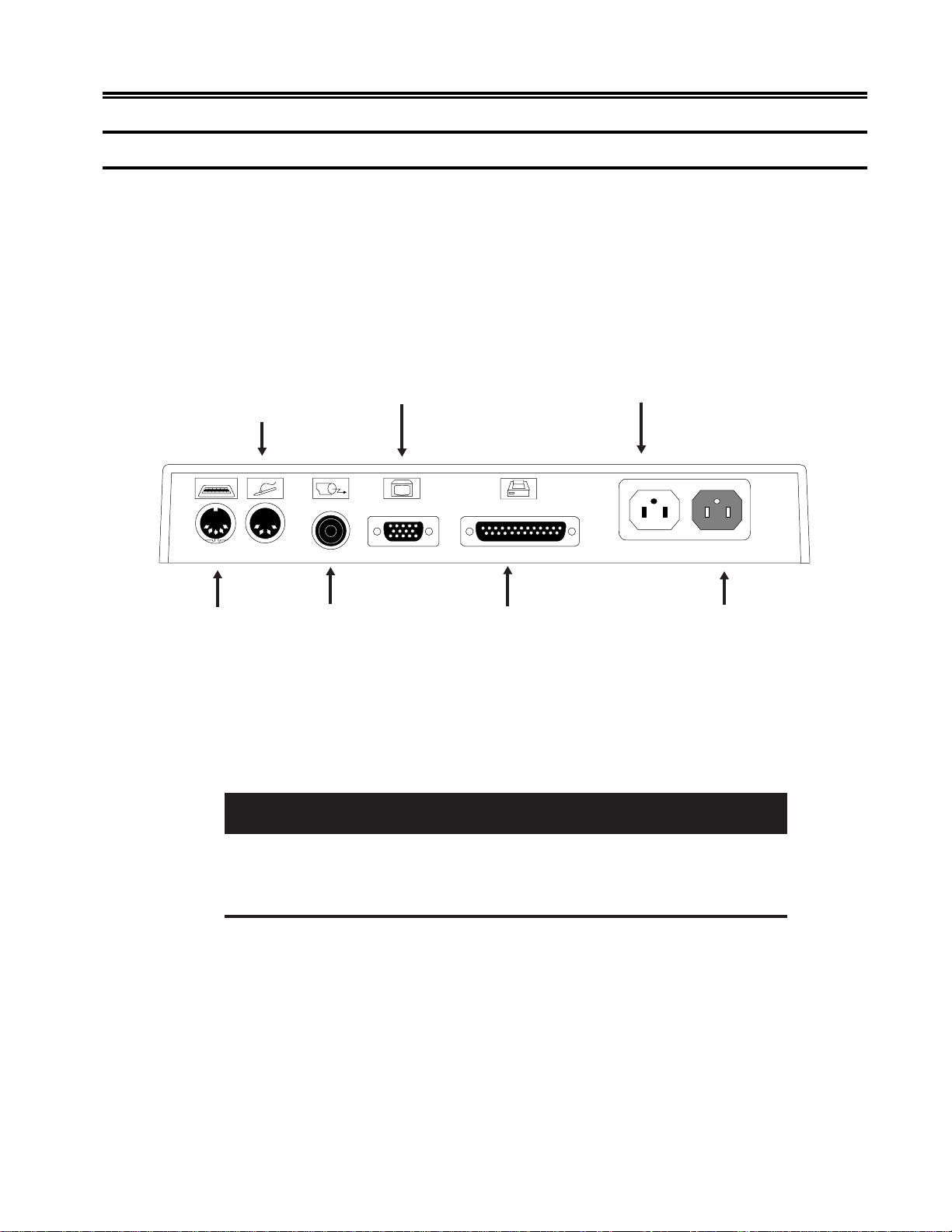
1) Place the Display element on top of the Logic element and place both within
connecting distance of an appropriate AC power outlet.
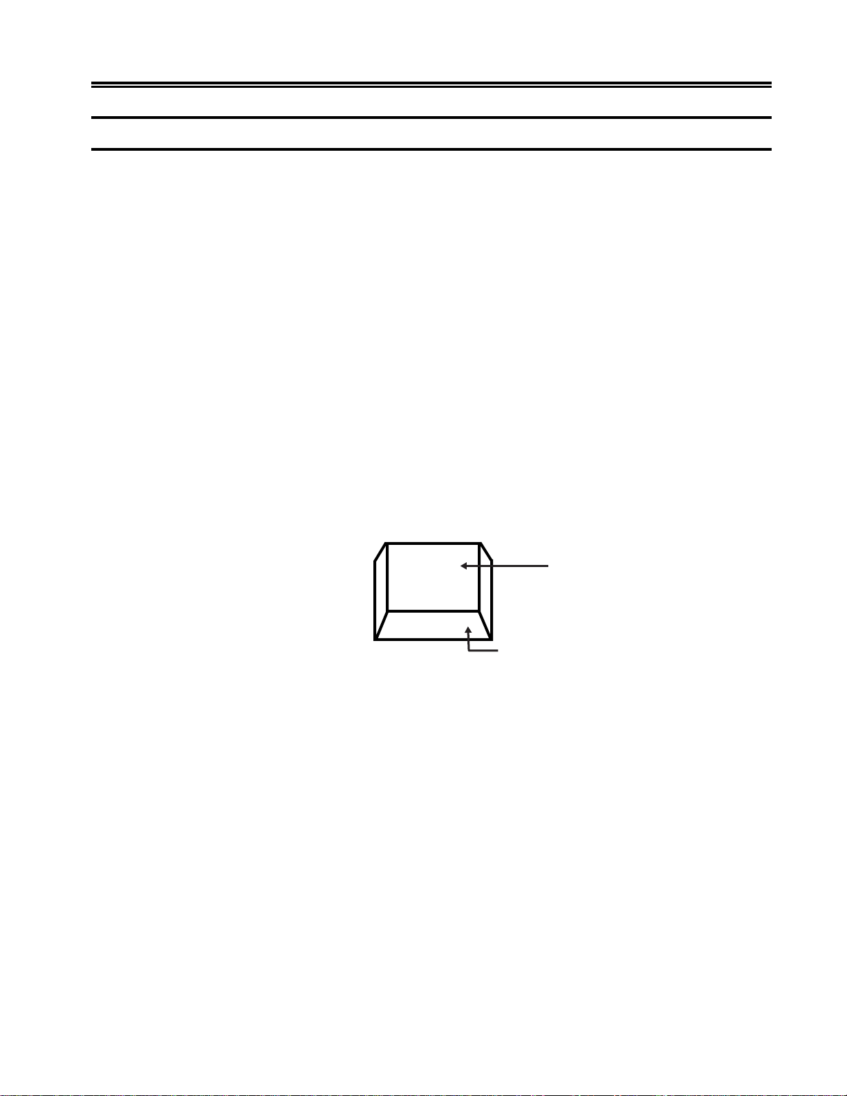
2) Place the keyboard in front of the Logic element. Pull out the feet underneath the
keyboard to adjust it to a higher setting, if desired. Insert the keyboard plug into the
keyboard connector on the back of the Logic element (Figure 2-1, below).
Customer Installation
Light Pen
Connector
Keyboard
Connector
Display Element
Coax
Connector
to
Logic Element
Connector
Printer
Cable
AC Power Cable
Connector
(to Display)
AC Power Cable
Connector
Figure 2-1. 1483 Receptacle Connectors
3) Refer to the owner’ s manual that comes with your monitor for instructions on ho w
to attach the monitor cable.
Warning
If the power rating on the Logic element is not equal to or greater than the power
rating on the Display element, do not plug the monitor cable into the Logic
element. Plug it into a wall receptacle.
4) For the host addressable or local screen pr int function, a printer connector is located
on the back of the Logic element (Figure 2-1, above). Attach the printer cable
(provided with the printer) to the printer connector on the back of the Logic element.
701344-003 2-3
Page 17

Customer Installation
5) Make sure that the Po wer-On/Off switch is set to O (Of f) on both the Logic element
and the Display element.
There are two AC power cables. Follow the instruction in Step 6 to install one power
cable and follow the instructions in Step 7 to install the other power cable.
6) Attach one end of the monitor AC power cable to the AC power cable connector
on the back of the Display element (see the booklet that came with the Display
element for the location of the AC power connector) and the other end to the AC
power connector on the back of the Logic element (Figure 2-1).
7) Plug one end of the power cord into the AC connector on the back of the Lo gic
element (Figure 2-1). Plug the other end of the AC power cord into a wall
receptacle.
Installing the Optional Light Pen
Follow these steps to install the optional light pen:
1) Remove the light pen and its holder from the protecti ve wrap.
2) Insert the light pen’s cable connector into the 4-pin receptacle on the rear of the
Logic element. Check to ensure that the connector is firmly seated. Figure 2-1 on
Page 2-3 shows the location of the light pen connector on the back of the Logic
element.
3) Peel the protectiv e cov er from the light pen holder’ s mounting surface.
4) Mount the light pen holder on the side of the display station.
5) Measure the amount of cord needed for the light pen to reach from the holder to any
point on the screen. Leaving this amount free, place the light pen cord into the cord
retainers.
Note: The light pen is not supported in Split Screen mode.
Connecting the Display Station to the Host Systems
Connect the display station to the host or to a controller with a coax cable up to 1500
meters (4920 feet) long, or a twisted-pair cable with a minimum length of 30.5 meters
(100 feet) and a maximum length of 277 meters (900 feet). Coax cable and twisted-pair
cables can be combined. The following formula shows lengths:
(coax length) + (5 x twisted-pair length)
Follow these steps to connect the 1483 to the host system or to a controller:
1) Locate the coax or twisted-pair cable extending from the controller.
< 1370 meters (4500 feet)
2-4 701344-003
Page 18

2) Align the end of the connector cable with the Coax connector that is on the back of
the Logic element (see Figure 2-1 on Page 2-3). Connect the cable and secure it in
place by turning the retaining ring clockwise until it is tight.
Setting Up the Display Screen
The 1483 is designed to operate with color SVGA and/or VGA monitors, or
monochrome SVGA or VGA monitors. Depending on whether you have a color or
monochrome monitor, follow one of the procedures below to set up the screen before
you turn power on the first time.
Color Monitor
1) Determine the type of monitor (SVGA, VGA, or combined SVGA/V GA) you have.
You will set the monitor to operate in SVGA or VGA mode.
2) Press and hold one of the following function keys while you turn the
Power-On/ O ff s wit ch t o On :
• F1 – Sets the monitor to color SVGA mode.
Customer Installation
• F2 – Sets the monitor to color VGA mode (default).
• F7 – For multifrequency monitors that can operate up to 42 KHz, sets the vertical
refresh rate to 75 Hz.
Monochrome Monitor
1) Determine whether you have a 14-inch VGA or 15-inch SVGA monochrome monitor
(measured diagonally).
2) Press and hold one of the following function k eys while you turn the Power-On/ Of f
switch to On:
• F3 – Sets the monitor to 14-inch monochrome VGA mode with “color” menus
that display varying monochrome intensities in different fields. This mode is
preferred for US operation.
• F4 – Sets the monitor to 14-inch monochrome VGA mode with “color” menus
that display varying monochrome intensities. This setting g ives a different set of
intensity defaults than those generated by pressing F3.
• F5 – Sets the terminal to 15-inch SVGA mode.
• F6 – Sets the monitor to 14-inch or 15-inch monochrome with overscan. (For
use only with monitors that support overscan).
701344-003 2-5
Page 19

Customer Installation
Conducting the Preliminary Operating Test
1) Ensure that the system control unit is powered on and operational.
2) T urn the Po wer On/Of f switch to Off (O) .
3) Set the Power-On/Off switch to On ( | ) while simultaneously holding down the
space bar. After a fe w seconds, an alarm sounds.
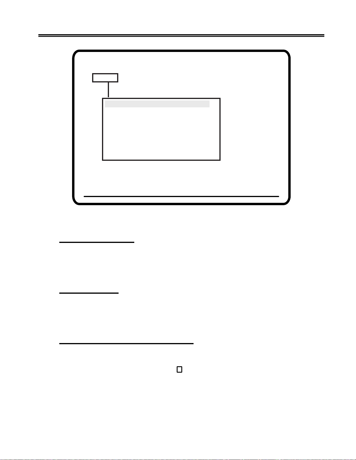
4) Continue to hold the space bar down until a screen lik e the one in Figure 2-2, below ,
is displayed. You may need to adjust the Brightness or Contrast control.
Offline Test Menu
Select One of the Following
User Menus
System Manager Menus
User Defined Data
Product ID 1483V (c)1995
Go Online
Figure 2-2. Offline Test Menu
5) If the display station is designated to operate with settings other than the default
modes, see “Offline Test Menu” on Page 3- 5 for a description of the Offline Setup
menus to change the modes. Obtain the settings designated for the display station
from the system operator. The controller to which the display station attaches
must be configured to support the settings selected. When the display station is set
correctly, it is ready to go online. Press the Reset key to display the cursor in the
upper left corner of the screen and the operator status row at the bottom.
6) If the screen does not have the cursor in the upper left corner and the operator status
row at the bottom, see Chapter 7, “Problem Determination and Maintenance.”
7) Installation of the display station is now complete. Certain settings may be changed
while online. See Figure 3-11, “Online Screen Menu” for further information.
2-6 701344-003
Page 20

Chapter 3. Setup Menus, Controls,
and Indicators
This chapter describes the display controls, keyboard controls, and display indicators on
the 1483 and its attached keyboard.
Display Controls
Refer to the installation booklet that comes with your Display element for an illustration
of the locations of the Brightness, Contrast, and other controls. An y controls not on the
display station are regulated from the setup menus and are described in the sections on
Online and Offline Setup mode.
Keyboard Operation Modes
Y ou can select either of two keyboard operation modes, Emulation mode or Nati ve mode.
The default setting is to emulate an IBM 3278 88-key keyboard. You can change the
keyboard operation mode by changing the keyboard type on the Offline K eyboard menu
(Figure 3-6 on Page 3-12).
With Nativ e mode selections, Ke yboard Definition mode is supported.
Emulation Mode
Emulation mode can be used with a 122-key or a 104-key keyboard. Emulation mode
causes the display station to provide to the controller con verted keyboard scan codes that
allow the attached keyboard to emulate a standard IBM 3278 88-key keyboard or an
IBM 3278 88-key keyboard with a PF pad. In Emulation mode, some keys on the 122key keyboard are not functional. The controller to which the display station is attached
must be configured to support Emulation mode.
701344-003 3-1
Page 21

Setup Menus, Controls, and Indicators
Native Mode
Native mode causes the display station to provide to the attached controller uncon verted
keyboard scan codes which are defined by the controller depending on how it is configured.
Native mode is available on the 102/103-key, 104-key, and 122-key keyboards. In
Native mode, all 122-key k eyboard functions are av ailable. Native mode also allo ws the
use of Keyboard Definition mode on the 122-key keyboard. To use Native mode, you
must be connected to one of the following controllers:
• MTX/MTC 1174 Network Controller
• Memorex T elex 1274 Control Unit at firm ware release lev el 11.0 or higher
• IBM 3174 Control Unit
• IBM 3274 Control Unit at configuration support D microcode release level 63.0 or
higher.
T o use Nati ve mode with a 102/103-ke y ke yboard, you must be connected to one of the
following controllers:
• MTX/MTC 1174 Network Controller
• Memorex Telex 1274 Control Unit at firmware release 16.0 or higher (if the 1274
supports Multiple Logic Sessions, firmware release 53.0 or higher)
• Memorex T elex 1374 Control Unit
• IBM 3174 Control Unit
• IBM 3274 Control Unit at configuration support D microcode release level 65.0 with
RPQ # 760825.
The control unit to which the 1483 is attached also must be configured to support Native
mode.
Keyboard Definition Mode
In Native mode, the 1483 supports Ke yboard Definition mode. Keyboard Def inition mode
enables you to modify the keyboard layout by using the control unit’ s Keyboard Definition
Utility. The attached control unit must be configured properly to support this feature.
3-2 701344-003
Page 22
Keyboard Controls
This section describes keys on the 102/103-key, 104-key, and 122-key keyboards that
control functions associated with the display.
Alt –Simultaneously press the Alt ke y and any other key to acti v ate functions specified
on the front key face. Only keys with labeled front faces ha ve alternate functions.
Shift –Press and hold the Shift key and press any key with a shifted function on the
keytop to activ ate that shift function.
Reset –Press the Reset key to restore keyboard operations after an error condition, to end
character insertion in Insert mode, or to terminate a printer identification sequence before
all characters have been entered.
Change Screen – Press the Change Screen key to toggle between sessions. The Change
Screen key does not work with all controllers. In Emulation mode, if the Change Screen
key does not function, press and hold the Alt key while you press the Insert key. If the
Change Screen key does not function in Nativ e mode, press and hold the Alt key while
you press the P A2 k ey.
Setup Menus, Controls, and Indicators
PA3 – The P A3 k ey is an additional function key. It does not work with all controllers.
The P A3 key does not function in Emulation mode.
Shift Function
Nonshift Function
Alt Function
Key Top
Key Face
Figure 3-1. Keyboard K ey Functions
Note: On some international keyboards, the Alt function is located on the top right
quadrant of the key .
701344-003 3-3
Page 23

Setup Menus, Controls, and Indicators
Each keyboard type contains autorepeat keys that repeat their functions as long as they
are pressed. The autorepeat keys include all keys that enter alphabetic, numeric, or symbol
characters, the space bar, all keys tha t assign or move the cursor position, and the following
special-purpose keys:
• Field Mark (Data Entry keyboards only)
• Duplicate (Data Entry keyboards only)
• Skip (Data Entry keyboards only)
Offline Setup Mode
All the controls described in “Online Setup Mode” except for the options on the Online
Printer menu (see Page 3-31) can be operated by entering Setup mode any time after the
display is powered on, whether online or offline. The following special adjustments are
made from Offline Setup mode only:
• Screen Size
• Partition
• Keyboard T ype
• Numeric Lock
• Keyless Security Lock
• Printer Type
• Host Addressable Print
• Offline T ests
• Screen Centering
• Password Protection
• Serial Number
• Play/Record Options
• Reset NVRAM
Check with the system operator before changing any of these control values.
T o enter Of fline Setup mode, perform one of the following steps:
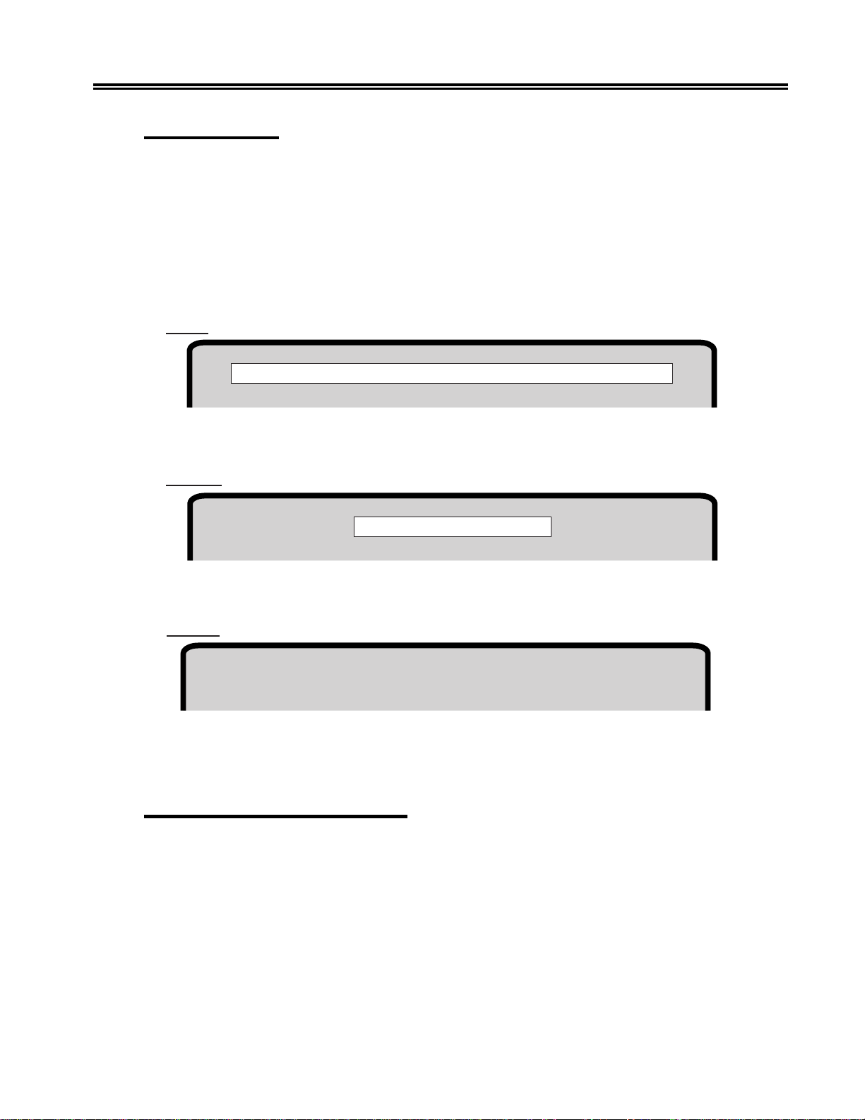
From the Online Miscellaneous menu, highlight Go Offline and press the Enter key . The
following message is displayed in blinking characters to warn you that data may be lost:
Data May Be Destroyed
Hit ENTER to Continue RESET to Abort
3-4 701344-003
Page 24

Press Reset to remain online with no loss of data, or press Enter to go offline.
With the display po wer off, pr ess and hold down the space bar and simultaneously turn
on the display station.
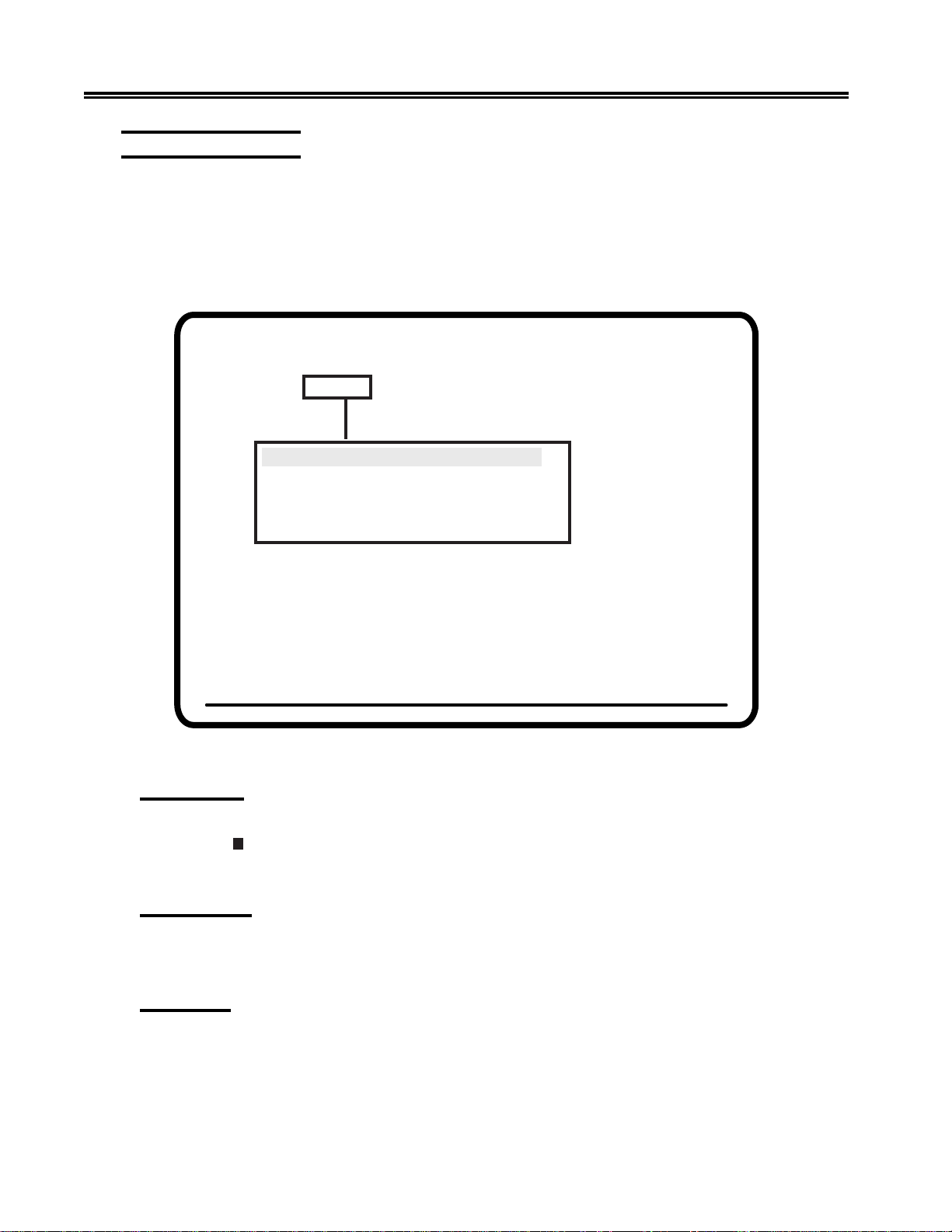
After either step is performed, the Offline Test menu (Figure 3-2, belo w) is displayed.
Offline Test Menu
Select One of the Following
Setup Menus, Controls, and Indicators
Or
Offline Test Menu
User Menus
System Manager Menus
User Defined Data
Product ID 1483 (c) 1993
Go Online
Figure 3-2. Offline Test Menu
Use the Up and Down Arrow keys to highlight User Menus on the Of fline T est menu and
press the Enter key . The Offline Screen menu is displa yed (Figure 3-3 on Page 3-7 ).
Offline T est Menu Selections
1) The User Menus selection displays offline menus for operator setup. Offline menus
include all Online functions as well as functions that can only be selected offline.
2) The System Manager Menus selection displays a menu for system setup by the
system manager. See Page 7-2 for detailed information.
701344-003 3-5
Page 25

Setup Menus, Controls, and Indicators
3) The User Defined Data selection displays a panel of Extended V ital Product Data
information. This panel is for information only . Extended V ital Product Data cannot
be entered or changed from the 1483. Extended Vital Product Data is entered from the
controller. See the documentation for your controller for information about entering
and changing Extended V ital Product Data.
4) The Go Online selection puts the display station online for normal operation.
User Menus
To display the Offline Menu screens, highlight
User Menus on the Offline Test menu and
press the Enter key. If password protection is
enabled (see Page 7-5), you are prompted to
enter the password. Enter the password and press
the Enter key. The offline Screen menu is
displayed (Figure 3-3 on Page 3-7).
Press the Left or Right Arrow key to highlight
Screen, Cursor, Keyboard, Printer,
Miscellaneous, or Color (the Color option is
displayed only if you have a color monitor) to
display other offline user setup menus.
Note: Y ou can print the of fline setup user menus. To print a menu, display the menu
on the 1483 screen and press the Print key .
Offline Screen Menu
All of the options in Figure 3-3 on Page 3-7 may not be displayed on your screen. The
options available to you depend on whether you are using a color or monochrome monitor .
:egaugnalunemegnahcoT
)a,neercsuneMenilffOehtmorF
ruofyekworrAthgiRehtsserp
litnusemit suoenallecsiM ,sreviD(
)soiraV,aenallecsiM,senedeihcsreV
no9–3erugiFeeS.detcelessi
.22–3egaP
)blitnuyldetaeperyekretnEehtsserP
.sraeppaegaugnaltcerroceht
,hcnerF,hsilgnEerasegaugnaL
.nailatIdna,hsinapS,namreG
3-6 701344-003
Page 26
Setup Menus, Controls, and Indicators
Offline Menu Screen
Screen Cursor Keyboard Printer Miscellaneous Color
MONOCASE/DualCase DualCase
Mark Unprotected No
MUP Character .
MUP overstrikes No
Row/Column Off
Screen Size 24 X 80 (Mod 2)
Partition On
Reverse Video On
Intensity Control Normal
Use Arrow Keys to choose item
Use ENTER Key to change item
RESET Key Exits
Figure 3-3. Offline Screen Menu
MONOCASE/DualCase
To select MONOCASE or DualCase mode, highlight MONOCASE/DualCase and
press the Enter key to toggle between MONOCASE and DualCase. When MONOCASE
is selected, all characters are displayed on the screen as uppercase letters. When
DualCase is selected, all characters are displayed as both upper- and lowercase.
Mark Unprotected
When activated, the Mark Unprotected Field indicator displays a selectable symbol in
each unprotected field on the screen. This enables you to recognize locations where
keystrokes can be entered. To activate the Mark Unprotected Field indicator, highlight
Mark Unprotected and press the Enter key to select Yes or No (the default).
Mark Unprotected Field Character (MUP)
To select a Mark Unprotected Field symbol, highlight MUP Character and press the
Enter key to display one of the following symbols: dot ( . ), two dots ( .. ), underline ( _ ),
overscore ( ¯ ), or character outline box (
If Mark Unpr otected (above) is set to No, your selection for MUP Character is ignored.
). The default is dot ( . ).
701344-003 3-7
Page 27

Setup Menus, Controls, and Indicators
MUP Overstrikes
With MUP Overstrikes set to Yes, the selected MUP symbol ov erstrikes the displayed
character. With No selected, the displayed character replaces the MUP character. To
change the MUP overstrikes option, highlight MUP Overstrikes and press the Enter
key to toggle between Yes and No (the default).
If Mark Unprotected (see Page 3-7) is set to No, your selection for MUP Overstrikes
is ignored.
Row/Column
When Row/Column is turned on, the current row and column position of the cursor is
displayed on the operator status row . The indicated position may not be the actual cursor
position on the display screen. The numbers indicate the location of the cursor in the
actual image that the display station receives from the host system. Highlight Row/
Column and press the Enter key to turn the cursor row/column display On or Off (the
default).
Screen Size
T o adjust the display screen, highlight Screen Size on the Of fline Screen menu and press
Enter to cycle through the four possible screen size settings:
• 24 X 80 (Mod 2) – default
• 32 X 80 (Mod 3)
• 43 X 80 (Mod 4)
• 27 X 132 (Mod 5)
The screen size displayed is the active screen size.
Partition
The partitioning function supported by the display station is completely a host
controlled function. The display receives partitioning commands from the host when
Partition is enabled on the Of fline Screen menu and Native T ypewriter is selected on
the Offline Keyboard menu (Figure 3-6 on Pag e 3-12). To enable the partition function,
highlight Partition and press the Enter key to toggle between On and Off until On is
displayed. The default value is On.
Reverse Video
The Reverse Video setting enables you to display blac k characters on a green, amber, or
white screen. To set the Reverse V ideo option, highlight Reverse V ideo and press the
Enter key to toggle between On (white characters on a black screen) and Off (black
characters on a white screen). The default setting is On.
Note: The Reverse V ideo feature is supported on 15-inch monochrome monitors only .
3-8 701344-003
Page 28
Setup Menus, Controls, and Indicators
Intensity Control
The Intensity Control setting enables you to determine the area to be highlighted. There
are three settings for Intensity Control: Normal (the default), Data only, and Highlight.
It is available only on monochrome monitors.
To use the Intensity Control option, you must first set the Reverse Video option On
(black characters on an amber, green, or white screen). Highlight Intensity Control and
press the Enter key to cycle through the choices: Normal (the default), Data Only, and
Highlight.
Normal – The entire background field, data area and nulls, is highlighted.
This is Normal Intensity.
Data only
– The background field, data only, is highlighted.
This is Data Only Intensity.
Highlight
– The foreground color is highlighted (only the data characters, not the nulls).
This is Highlight Intensity.
Figure 3-4. Intensity Control Options
Leaving the Offline Screen Menu
T o leave the Of fline Screen menu, use the Left and Right Arrow ke ys to highlight another
offline setup menu, or press the Reset key to lea ve Offline Setup mode and display the
Offline T est menu.
701344-003 3-9
Page 29
Setup Menus, Controls, and Indicators
Offline Cursor Menu
T o display the options on the Offline Cursor menu, use the Left and Right Arro w keys to
highlight Cursor on any offline setup menu and press the Enter key . The Offline Cursor
menu is displayed (Figure 3-5, below).
All of the options in Figure 3-5 may not be displayed on your screen. The options av ailable
to you depend on whether you are using a color or monochrome monitor.
Offline Menu Screen
Screen Cursor Keyboard Printer Miscellaneous Color
Cursor Size Block
Cursor Blink No
Rule Style Line (-)
Stationary Rule Moves
Rule Color C1
Use Arrow Keys to choose item
Use ENTER Key to change item
RESET Key Exits
Figure 3-5. Offline Cursor Menu
Cursor Size
The Cursor Size option enables you to choose an underline cursor ( _ ) or a block
cursor (
). Highlight Cursor Size and press the Enter key to toggle between Block
(the default) and Underline.
Cursor Blink
You can select a blinking cursor or a nonblinking cursor by highlighting Cursor Blink
and pressing the Enter key to toggle between Off (the default) and On.
Rule Style
You can select the rule style for the rule function. The rule style can be a line ( – ),
cross ( + ), or bar ( | ). To select a rule style, highlight Rule Style, then press the Enter
key to toggle through the choices Line ( – ) (the default), Cross ( + ), and Bar ( | ).
T o use the rule cursor when y ou are online, press the Rule key.
3-10 701344-003
Page 30

Setup Menus, Controls, and Indicators
Stationary Rule
The rule cursor can function as a horizontal or vertical ruler . If you select Stationary for
the Stationary Rule, the rule line does not move with the cursor, but remains as an
alignment aid for columns or rows. (T o relocate the rule line to the current position of the
cursor, press the rule key twice.)
If you select Moves for the stationary rule, the rule moves with the cursor .
To set the stationary rule, highlight Stationary Rule and press the Enter key to toggle
between Moves (the default) and Stationary.
T o use the rule cursor w hen you are online, press the Rule key.
Rule Color
Note: To use the rule cursor when you are online, press the Rule key.
F or color monitors:
The rule can be set to any of the selectable colors. To chang e the rule color, highlight
Rule Color and press the Enter key to cycle through the color options. The rule color
you select is displayed on the screen. The color options are:
• C1 (blue) – default setting
• C2 (red)
• C3 (pink)
• C4 (green)
• C5 (turquoise)
• C6 (yellow)
• C7 (white)
F or monochrome monitors:
The rule can be set to be intensified or normal. Press the Enter key to toggle between
Intensified (the default) and Normal.
Leaving the Offline Cursor Menu
T o leav e the Offline Cur sor menu, use the Left and Right Arro w keys to display another
offline setup menu, or press the Reset key to lea ve Offline Setup mode and display the
Offline T est menu.
701344-003 3-11
Page 31

Setup Menus, Controls, and Indicators
Offline Keyboard Menu
T o display the options on the Offline K eyboard menu, use the Left and Right Arrow ke ys
to highlight Keyboard on any offline setup menu and press the Enter key. The Offline
Keyboard menu is displayed (Figure 3-6, below).
Offline Menu Screen
Screen Cursor Keyboard Printer Miscellaneous Color
Alarm V olume 3
Click Enable No
Click V olume 3
Cursor Speed Slow
Repeat Delay Medium
Keyboard T ype Native Typewriter
Numeric Lock On
Change KEYLESS Password
Use Arrow Keys to choose item
Use ENTER Key to change item
RESET Key Exits
Figure 3-6. Offline Keyboard Menu
Alarm Volume
T o adjust the audible alarm volume, highlight Alarm V olume and press the Enter key to
cycle through the volume choices of Off, 1 (quietest), 2, 3, 4, and 5 (loudest). The alarm
sounds each time you press the Enter key (except for Off) so you can check the lev el of
each setting. The default setting is 3.
The alarm sounds when a character is entered in the next-to-last character position of the
screen (if the last character position is unprotected) or when the host system signals the
display station to sound the alarm. Refer to the system user’s guide for additional
information about alarm signals from the host system.
Click Enable
When the display station goes online, the keyboard click performs according to how the
Click Enable option was last set. After the display station has gone online, the
keyboard click can be activated or deactiva ted by the controller, such as when an “Input
Inhibited” error occurs. You can also toggle the keyboard click on and off by holding
down the Alt k ey while you press the F24 ke y.
3-12 701344-003
Page 32

Setup Menus, Controls, and Indicators
When the display station goes offline, the menu setting for Click Enable is sa ved. Changes
made to the keyboard click by the controller or by the Alt/F24 toggle key combination
are not saved when the display station goes offline.
Press the Up or Down Arro w key to highlight Click Enable, then press the Enter key to
toggle between Yes and No (the default). Select Yes to make the keyboard click with
each keystroke or select No to deactiv ate the ke yboard click.
Click Volume
T o adjust the keyboard click v olume, highlight Click V olume and press the Enter key to
cycle through the volume choices of Off, 1, 2, 3 (the default), 4, and 5.
If Click Enable (see Page 3-12) is turned off, setting Click Volume to 1, 2, 3, 4, or 5
does not cause the keyboard to click. If Click Volume is set to Off, an Input Inhibited
condition does not cause the keyboard to click.
Cursor Speed
T o change the horizontal cursor speed, highlight Cursor Speed and press the Enter key
to cycle through the choices Slow (the default), Medium, and Fast.
Repeat Delay
You can change the time interval of starting the continuous display of characters on
autorepeat keys by changing the autorepeat delay speed control. To adjust the speed
delay, highlight Repeat Delay and press the Enter key to cycle through the choices
Short, Medium (the default), and Long.
Keyboar d Type
Note: Check with the system operator before changing this value.
The Keyboard T ype setting enables you to select a keyboard/display conf iguration. The
system operator will know in which mode the keyboard should operate. The default
keyboard type, Native T ypewriter, is set at the factory before the 1483 is shipped to you.
The following keyboard types are av ailable:
• Emulate 88 Key KBD – Enables a 122-key to emulate an IBM 3278 88-key keyboar d.
If you intend to use Host Addressable Print, do not select this option. Do not select
this option if you have an 88-key ke yboard with a tripad.
• Emulate 88 Key PF-Pad – Enables a 122-key keyboard whose numeric pad has
PF13-24 keys in place of numbers to emulate an IBM 3278 88-key keyboard. If you
intend to use Host Addressable Print, do not select this option.
• Native Mode - 00
(Native Mode European Typewriter Keyboard)
• Native T ypewriter
(Native Mode US Typewriter Keyboard)
701344-003 3-13
Page 33

Setup Menus, Controls, and Indicators
• Data Entry Keyboard
(Native Mode Data Entry K eyboard)
• APL Keyboard
(Native Mode APL Ke yboard)
• User Define - 01
(Native Mode Typewriter – Controller Keyboard Definition Utility required)
• User Define - 02
(Native Mode Typewriter – Controller Keyboard Definition Utility required)
• User Define - 03
(Native Mode Typewriter – Controller Keyboard Definition Utility required)
• User Define - 04
(Native Mode Typewriter – Controller Keyboard Definition Utility required)
• User Define - 01+
(Native Mode Data Entry – Controller Keyboard Def inition Utility required)
• User Define - 02+
(Native Mode Data Entry – Controller Keyboard Def inition Utility required)
• User Define - 03+
(Native Mode Data Entry – Controller Keyboard Def inition Utility required)
• User Define - 04+
(Native Mode Data Entry – Controller Keyboard Def inition Utility required)
To change the keyboard selection, highlight Keyboard Type on the Offline Keyboard
menu and press Enter until the required selection is displayed.
Numeric Lock
Note: Check with the system operator before changing this value.
The Numeric Lock restricts the characters that can be keyed into a designated numeric
field.
T o enable the numeric lock, highlight Numeric Lock and press the Enter k ey to toggle
the feature On (default value) or Off.
Changing the Keyless Password
You can modify the password for the Electronic Security Lock by doing the follo wing:
1) Move the pointer to the Change KEYLESS Passwo rd prompt and press Enter .
2) You are then prompted to input the current password. As eac h keystroke is input,
an * is displayed in the results column. If an incorrect password is input, password
prompts are removed. To retry, press Enter to restore the prompt.
Note: The default password as shipped or after RESET NVRAM is OFF. OFF
disables the electronic keylock when online.
3-14 701344-003
Page 34

3) If you entered the password correctly, you are prompted for a new password. The
next three keystrokes are taken as the ne w password.
4) You are then prompted to reenter the new password to verify the change. When the
third keystroke is entered, all of the password prompts are removed. If the keystrok es
do not match, the password is not changed.
Leaving the Offline Keyboard Menu
T o leave the Off line Keyboard menu, use the Left and Right Arrow k eys to display another
offline setup menu, or press the Reset key to exit Offline Setup mode and display the
Offline T est menu.
Offline Printer Menu
T o display the options on the Offline Printer menu, use the Left and Right Arrow k eys to
highlight Printer on any offline setup menu and press the Enter key . The Offline Printer
menu is displayed (Figure 3-7, below).
Setup Menus, Controls, and Indicators
Offline Menu Screen
Screen Cursor Keyboard Printer Miscellaneous Color
Printer 1201
Program Setup Strings for Prints
Host Addressable Print Yes
Printer format control Terminal
Suppress automatic line feed when:
CR at maximum print position + 1 No
FF at print end No
NL at maximum print position + 1 No
FF ignored when not in first print position No
FF takes position if followed by data Yes
FF at end of print No
Transparent Coax
Use Arrow Keys to choose item
Use ENTER Key to change item
RESET Key Exits
Figure 3-7. Offline Printer Menu
701344-003 3-15
Page 35

Setup Menus, Controls, and Indicators
Highlight Printer on the Offline Printer menu and press Enter to cycle through these
choices:
• 4201 Proprinter (IBM Proprinters II and III)
• 4202 Proprinter (IBM Proprinters II and III XL)
• 1173
• COAX
• 1301
• 1302
• 1201 (default setting)
• 1202
• 1808
• LaserJet (HP LaserJet Series II)
• ThinkJet (HP ThinkJet)*
• DeskJet (HP DeskJet 500)*
• FX1050 (Epson)*
• LQ1050 (Epson)*
• 4207 (IBM Proprinter X24E)
• 4208 (IBM Proprinter XL24E)
• 5202 (IBM Quietwriter III)
• 5204 (IBM Quickwriter)
• 4019 (IBM LaserPrinter)
• Plain (generic printer)
* If you select this printer, you must set the DIP or Mode Select switches on the printer .
See Appendix A, “Printer Information,” for the correct switch settings.
Caution
Use of any printer other than those specified could produce unpredictable results
and is neither recommended nor supported.
3-16 701344-003
Page 36

Setup Menus, Controls, and Indicators
Program Setup Strings for Prints
You can specify print a ttributes for any supported printer by setting the power-on
sequence. The programmed power-on sequence overrides the printer’s resident
pow er-on sequence when the printer is powered on or the display station goes online.
For screen printing, the programmable setup string is appended to the normal printer
initialization string before each print job. For host addressable printing, options set on
the Online Printer menu override the programmable setup strings for all printers except
the Plain printer.
Note: Only the following commands are sent to the Plain printer:
• Line feed
• Form feed
• Carriage return
• Backspace
• Spaces for horizontal tabs
When you set a power-on sequence, the printer prints only in the font and style
specified by the power -on sequence. For example, if you set the po wer-on sequence for
Courier 10-point, bold, italic, everything the printer prints is in Courier 10-point, bold,
italic.
To set the power-on sequence, highlight Program Setup Strings for Prints and
press the Enter key. The Programmable Setup Strings for Prints screen is displayed
(Figure 3-8 on Page 3-18).
Use the Up and Down Arrow keys to highlight a position, then use the Left and Right
Arrow keys to cycle through the escape codes (00 through FF). The initial power-on
value for each position is 00.
T o set all positions to 00 and disable this feature, press the Clear k ey.
T o leave the Programmable Setup Strings for Prints menu and return to the Offline Printer
menu without saving any changes, press the Reset key.
T o leave the Programma ble Setup Strings for Prints menu and return to the Offline Printer
menu with the changes saved, press the Enter key . When you leav e the Programmab le
Setup Strings for Prints menu, the setup strings are sent to the printer.
701344-003 3-17
Page 37

Setup Menus, Controls, and Indicators
Programmable Setup Strings for Prints
1st Position 00 17th Position 00
2nd Position 00 18th Position 00
3rd Position 00 19th Position 00
4th Position 00 20th Position 00
5th Position 00 21st Position 00
6th Position 00 22nd Position 00
7th Position 00 23rd Position 00
8th Position 00 24th Position 00
9th Position 00 25th Position 00
10th Position 00 26th Position 00
11th Position 00 27th Position 00
12th Position 00 28th Position 00
13th Position 00 29th Position 00
14th Position 00 30th Position 00
15th Position 00 31st Position 00
16th Position 00 32nd Position 00
Use UP/DOWN Cursor Keys to select position to change
Use LEFT/RIGHT Cursor Keys to alter data at selected position
Use ENTER Key to make changes and return to previous menu
Use RESET Key to return to previous menu
Use CLEAR Key to set all positions to 00
Figure 3-8. Programmable Setup Strings f or Prints Screen
Host Addressable Print
The host addressable print feature enables the host to send print requests to the 1483’s
attached printer. LU2 (screen) prints are always formatted by the display according to
the printer menu selections.
T o enable or disable host addressable print, highlight Host Addressable Print and press
the Enter key to toggle between Yes (the default) and No. Host addressable print cannot
be enabled if an Emulate 88-key keyboard option is selected on the Offline K eyboard
menu (Figure 3-6 on Page 3-12), or if COAX is selected as the Printer on the Offline
Printer menu.
Controllers that support host addressable print are the MTX/MTC 1174 Network
Controller, Release 7.0 and higher, and the Memore x Telex 1374 Control Unit, Release
6.0 and higher.
Note: The host addressable print feature supports LU1 SCS commands.
If host addressable print is enabled, the Adjusting Line Feed and Adjusting Form
Feed options are displayed.
Printer Format Control
The printer format control feature enables the user to specify whether the formatting of
LU1 or LU3 will be handled by the display .
3-18 701344-003
Page 38

Setup Menus, Controls, and Indicators
If you select System, then formatting of LU1 or LU3 will not be handled by the display .
In addition, CPI/LPI menu information will not be used to initialize the printer , and there
will not be automatic form feed or new line performed by the display .
If you select T erminal, the default, the data for LU1 and LU3 prints will be handled by
printer menu selections.
Adjusting Line Feed
You can configure the printer to suppress an automatic line f eed by selecting one of the
following options:
Suppress automatic line feed when:
Note: In the following options, CR means carriage return, FF means form feed, and
NL means new line.
• CR at maximum print position + 1 – If you select Yes for this option, when the
printer reaches the maximum line position + 1 (the end of the print line), the carriage
returns to the beginning of the line without a line feed. The next printed characters
will overwrite the current line of printed characters.
If you select No (the default) for this option, when the printer reaches the end of the
line, the carriage returns to the beginning of the line and drops down one line.
• FF at print end – If you select Yes for this option, the printer does not execute a line
feed after a form feed.
If you select No (the default) for this option, the printer executes a line feed after a
form feed. Characters printed on the new page begin on the second line.
• NL at maximum print position + 1 – If you select Yes for this option, the print e r
does not execute a line feed if there is a new line command at the maximum print
position + 1 (the end of the print line). The printer begins printing o n t he n ext line .
If you select No (the default) for this option, when the printer reaches the end of the
line, it executes two line feeds.
Adjusting Form Feed
You can configure the printer to adjust the form feed by selecting one of the following
options:
701344-003 3-19
Page 39

Setup Menus, Controls, and Indicators
FF ignored when not in first print position
If you select Yes for this option, a form feed character in the first position or next to the
maximum print position is executed while form feed commands in any other positions
are printed as blank characters and are otherwise ignored.
If you select No (the default) for this option, all form feed commands are executed.
FF takes position if followed by data
If you select Yes for this option, if the form feed character is not at the end of the print
data, a form feed is executed and a blank character is printed in the first position on the
next page. Subsequent printing starts in the second position on the new page.
If you select No (the default) for this option, the form feed character is not printed as a
blank character and subsequent printing starts in the first position on the new page.
FF at end of print
If you select Yes for this option, the printer ejects the last printed page and subsequent
printing begins on the new page.
If you select No (the default) for this option, the last page is not ejected and a line feed is
executed. Subsequent printing begins on the ne w line of the current page.
T ransparent
Note: Check with your system manager before changing this option.
If Transparent is set to Coax (3287 emulation), data included in an SCS Transparent
Mode command (35H) is printed in the LU1 environment as follows:
• Valid EBCDIC characters are translated and printed normally.
• Inv alid EBCDIC characters (SNA character string [SCS] commands) are printed as
hyphens.
If Transparent is set to ASCII, all data included in the command is sent through to the
printer untranslated. The following setup values are not sent to the printer during
initialization:
• Chars/Inch
• Lines/Inch
• Quality
T o set the T ransparent option, highlight Transpar ent on the Offline Printer menu, then
press the Enter key to toggle between Coax (the default) and ASCII.
3-20 701344-003
Page 40

Setup Menus, Controls, and Indicators
Printer TRPQs
A collection of printer TRPQs can be accessed from the Offline Printer menu by pressing
the F9 (or PF9) key. The TRPQs are software features that permit additional printer
controls. The TRPQs are shown below:
QPRTretnirP
rebmuNnoitpircseD
1nahtsselerahcihwtnirPelbasserddAtsoHmorfsetybllasdneS
dna,)CSE(HB1otH72segnahC.degnahctonsitnuocnmuloC
.tisdnesneht
2otH1Anoitacolsecrof,elbatetalsnartNEGERotCIDCBEehtnI
).edlit(HB3
3.231otenil/sretcarahcmumixamsecroF
4rellortnocgnirongi,elbatetalsnartNEGERotCIDCBE.S.UsdaoL
.elbatdettimsnart
5otdegnahcebottonRC,ME,LNsesuac,stnirpdettamrofnI
.secaps
6.tnirp1ULfodneehttadeefmrofoN
.degnahcnuretnirpehtotsdnammocSCStonerahcihwdnaH04
To enable any Printer TRPQ, do the follo wing:
1) From the Offline Printer menu, press F9 (or PF9)
Active Print TRPQ numbers appear on the Status line. If no numbers appear, no
TRPQs are active.
2) Press the PF key that corresponds to the TRPQ number you want to enable. For
example, to enable Printer TRPQ number 3, press the PF3 key .
The number of the enabled TRPQ appears on the status line for three seconds.
To disable a Printer TRPQ, do the following:
1) From the Offline Printer menu, press F9 (or PF9).
Active Printer TRPQ numbers appear for three seconds.
2) Press the PF key that corresponds with the number of the TRPQ you want to disable.
For example, to disable TRPQ number 4, press the F4 (or PF4) ke y.
Leaving the Offline Printer Menu
T o leav e the Offline Printer menu, use the Left and Right Ar row ke ys to display another
offline setup menu, or press the Reset key to lea ve Offline Setup mode and display the
Offline T est menu.
701344-003 3-21
Page 41
Setup Menus, Controls, and Indicators
Offline Miscellaneous Menu
T o display the options on the Offline Miscellaneous menu, use the Left and Right Arrow
keys to highlight Miscellaneous on any offline setup menu and press the Enter k ey . The
Offline Miscellaneous menu is displayed (Figure 3-9, below).
Offline Menu Screen
Screen Cursor Keyboard Printer Miscellaneous Color
Setup Language English
Dim Timer 10
Dim Style Monitor Off
Power Down 30
Light Pen Click On
Coax Indicator Off
Use Arrow Keys to choose item
Use ENTER Key to change item
RESET Key Exits
Figure 3-9. Offline Miscellaneous Menu
Setup Language
Y ou can choose between English (the default), Français, Deutsch , Español, and Italiano
for the language on the setup menus.
To change the current setting, highlight Setup Language and press the Enter key to
cycle through the available settings. As each choice is selected, the menu changes to that
language and all menus continue to be displayed in that language until changed again.
Dim Timer
The Dim Timer controls when the Auto Screen Cutoff function tak es effect. When this
function is set, the screen blanks in a specified number of minutes if the display station
does not receive data from the keyboard or a host system. The Dim Style section pro vides
information for which of the two methods of screen blanking is active.
To enable this function, highlight Dim Timer and press the Enter key to c ycle through
Off (no dim), 5, 10, 15, . . ., 55, 60. The default is 10 minutes.
Note: The Auto Screen Cutoff function does not work while the display station is in
Setup mode.
3-22 701344-003
Page 42

Setup Menus, Controls, and Indicators
Dim Style
When Status Ro w Only is selected and the display has been inacti ve for the amount of
time set in the Dim Timer , the screen blanks, and only the operator status row and cursor
are displayed. The
to restore the screen without adding characters. Also, if the host initiates a write message,
the screen is restored.
When Monitor Off is selected and the display has been inactive for the amount of
time set in the Dim Timer, the entire monitor screen goes black. For TCO-compatib le
monitors, this is Standby Mode which is a Power Saver feature. A keystroke or host
write restores the screen in under three seconds. For non-TCO compatible monitors,
Status Row Only must be selected.
Note: If Electronic Keylock has been activated in the Offline menu by inserting a
password other than Off, Auto Screen cutof f will acti v ate Electronic K eyloc k.
A keystroke restores the screen and then the Electronic K eylock password must
be entered to allow use of the display .
Power Down
When turned on, the Power Down timer option cuts power to the monitor if it is plugged
into the back of the Logic element. The Power Down takes effect in the specif ied number
of minutes after the screen is blanked by the Auto Screen Cutof f function (Dim T imer
option). The default setting is 30 minutes.
symbol is displayed on the operator status row . Press the space bar
For example, if the Dim T imer is set for 10 minutes and the Power Do wn timer is set for
30 minutes, the screen will blank after 10 minutes and
status row. After 30 additional minutes, the power to the monitor will be cut off. To
return power and to restore the screen, press the space bar. If the host initiates a write
message, power is returned, and the screen is restored.
Note: Because the monitor may require warm-up time, restoration of the screen may
not be immediate.
Note: The Power Down function does not w o rk while the display station is in Setup
mode.
will be displayed on the operator
Light Pen Clicker
T o turn the light pen clicker on or off, highlight Light P en Click and press the Enter key
to toggle the function to On (default) or Off.
Coax Indicator
When this feature is turned on, a filled circle ( )is displayed in position 69 of the status
row to indicate an active coax line when the display station is online. An open circle
(
) indicates no coax activity and a blinking circle indicates a very slow poll cycle
indicative of a coax line being disconnected then reconnected. If the display station
displays a blinking circle, power down the display for at least 10 seconds before turning
the power on to reestablish communication. The Coax indicator overrides other status
line information in position 69 because it is normally used as a diagnostic feature.
701344-003 3-23
Page 43

Setup Menus, Controls, and Indicators
T o turn the Coax indicator on or off, highlight Coax Indicator and press the Enter ke y to
toggle the indicator On or Off (default).
Leaving the Offline Miscellaneous Menu
T o leav e the Of fline Miscellaneous menu, use the Left and Right Arro w ke ys to display
another offline setup menu, or press the Reset key to exit from Of fline Setup mode and
display the Offline Test menu.
Offline Color Menu
The Color option and Color menu are displayed only if a color monitor is attached to the
1483. To display the options on the Offline Color menu, use the Left and Right Arrow
keys to highlight Color on any offline setup menu and press the Enter ke y. The Of fline
Color menu is displayed (Figure 3-10, below).
Offline Menu Screen
Screen Cursor Keyboard Printer Miscellaneous Color
Use Arrow Keys to choose item
Use ENTER Key to change item
RESET Key Exits
Figure 3-10. Offline Color Menu
Color 4 Color
Unprotected Normal C4
Unprotected Highlighted C2
Protected Normal C1
Protected Highlighted C7
Background Color C0
C1 Blue 31
C2 Red 11
C3 Pink 40
C4 Green 21
C5 Turquoise 26
C6 Yellow 16
C7 White 63
Reset to Default Colors
3-24 701344-003
Page 44

Setup Menus, Controls, and Indicators
Color
T o change the display color selections, highlight Color and press the Enter key to c ycle
through the selections. When a selection is displayed, it is activ e.
Note: If you select the same color for the foreground and background, the foreground
color defaults to black.
If you select the same color for the background and highlighted fields, the
highlighted fields default to black and the characters in the highlighted fields
default to the background color .
Color selections are:
• 2 Color – Unprotected Normal and Protected Normal fields are C4 (green),
Unprotected Highlighted and Protected Highlighted fields are C7 (white), and
Background Color is C0 (black). You can change the factory set default colors
assigned to C4 and C7 by changing the colors assigned to the fields, as described in
“Changing the Color Settings, ” below , but you cannot change the color numbers (C4
and C7) assigned to the fields.
• 4 Color – Unprotected Normal is C4 (green), Protected Normal is C1 (blue),
Unprotected Highlighted is C2 (red), Protected Highlighted is C7 (white), and
Background Color is C0 (black). You can change the factory set default colors
assigned to C1, C2, C4, and C7 by changing the colors assigned to the fields, as
described in “Changing the Color Settings, ” belo w, but you cannot change the color
numbers (C1, C2, C4, and C7) assigned to the fields.
• 4 Color Programmable – Unprotected Normal is C4 (green), Pr otected Normal
is C1 (blue), Unprotected Highlighted is C2 (red), Protected Highlighted is C7
(white), and Background Color is C0 (black). Y ou can chang e the factory-set default
colors assigned to C1, C2, C4, and C7 by changing the colors assigned to the fields,
as described in “Changing the Color Settings, ” below . You can also change the default
color numbers (C1, C2, C4, and C7) to any of the seven a vailable colors (C1 through
C7).
To change the color number assigned to a field, use the Up and Down Arrow keys to
highlight the field you want to change (Unprotected Normal, Protected Normal,
Unprotected Highlighted, Protected Highlighted, or Background Color), then press
the Enter key to scroll through the color numbers (C1 through C7).
Changing the Color Settings
1) Use the Up and Down Arrow ke ys to highlight one of the following color c hoices:
C1 Blue
C2 Red
C3 Pink
C4 Green
C5 Turquoise
C6 Yellow
C7 White
701344-003 3-25
Page 45

Setup Menus, Controls, and Indicators
2) Press the Enter key to c ycle up (increment) through numbers 1 through 63. As each
new number is displayed, the color of the number changes. For example, if you
change C1 Blue from 10 (the default setting) to 55 (white), all fields to which C1
Blue has been assigned are now white.
If you pass a number you want to assign to a color, use the space bar to c ycle down
(decrement) through the numbers.
Note: Changing a color setting on the Offline Color menu changes that color for both
base fields and extended attributes (EABs).
Background Color
Select one of the following for the background color:
C0 Black
C1 Blue
C2 Red
C3 Pink
C4 Green
C5 Turquoise
C6 Yellow
C7 White
C0 is the default background color .
You can change the shade of background colors C1 through C7 by following the
directions in “Changing the Color Settings” on P age 3-25.
Returning to the Default Color Settings
T o return the color settings to the factory set defaults, use the Up and Do wn Arrow ke ys
to highlight Reset to Default Colors and press the Enter key . The follo wing message is
displayed:
Data May Be Destroyed
Hit Enter to Continue or Reset to abort
Press the Enter key again. The colors return to the factory set defaults.
Leaving the Offline Color Menu
To leave the Of fline Color menu, use the Left and Right Arro w k eys to display another
offline setup menu, or press the Reset key to exit from Offline Setup mode and display
the Offline Test menu.
3-26 701344-003
Page 46

Online Setup Mode
The following parameters are set or changed utilizing full screen menus that are displayed
after you enter Setup mode. Setup mode can be entered at any time while the display
station is operating either online or offline. To enter Setup mode, perform the following
steps:
1) For the 104- or 122-key keyboard,
press the Alt ke y and the Setup ke y.
For the 102/103-key keyboard, press
the Shift and the Setup key .
2) If password protection is enabled (see
Page 7-5), you are prompted to enter
the password. Enter the password
and press the Enter key. The
Online Screen menu is displayed
(Figure 3-11 on Page 3-28).
3) Press the Left or Right Arrow ke y to
highlight Scr een, Cursor , Keyboard,
Printer, Miscellaneous, or Color
(the color option is available if the
1483 is attached to a color monitor) to
display other offline user setup
menus.
Setup Menus, Controls, and Indicators
To change menu language:
a) From the Online Menu screen,
press the Right Arrow key four
times until
Verschieden es, Misc ell an ea, Varios)
is selected. See Figur e 3–15 on
Page 3–38.
b) Press the Enter key repeatedly until
the correct language is displayed.
Languages ar e Eng l i sh , French,
German, Spanish, and Italian.
Miscellaneous
(Divers,
4) As each menu name is selected, a full screen menu with selectable functions to set
or change is displayed. Use the Up and Down Arrow keys to highlight the item to
change and the Enter key to toggle through possible settings.
5) The Online Miscellaneous menu contains a selection, Go Offline, that enables you
to enter Offline Setup to make adjustments that can only be made offline. This
selection forces a simulated power-of f/power-on with a ke y pressed. The following
adjustments can be made only from the Offline Menu screens (Page 3-4):
• Screen Size
• Partition
• Keyboard T ype
• Numeric Lock
• Keyless Security Lock
• Printer Type
• Host Addressable Print
• Offline T ests
• Screen Centering
• Password Protection
• Serial Number
701344-003 3-27
Page 47

Setup Menus, Controls, and Indicators
• Play/Record Options
• Reset NVRAM
6) When you finish selecting options on an Online Setup menu, press the Reset ke y to
store the current values or continue to select options on other Online Setup menus.
Press the Reset key after selecting all options to store all settings and exit Online
Setup mode.
Note: Y ou can print the online user setup menus. T o print a menu, display the menu on
the 1483 screen and press the Print key .
Online Screen Menu
All of the options in Figure 3-11, below, may not be displayed on your screen. The
options available to you depend on whether you are using a color or monochrome monitor .
Online Menu Screen
Screen Cursor Keyboard Printer Miscellaneous Color
MONOCASE/DualCase DualCase
Mark Unprotected No
MUP Character .
MUP overstrikes No
Row/Column Off
Reverse Video On
Intensity Control Normal
Use Arrow Keys to choose item
Use ENTER Key to change item
RESET Key Exits
Figure 3-11. Online Screen Menu
All the options on the Online Screen menu are available on the Of fline Screen menu. See
“Offline Screen Menu” on Page 3-6 for more information about these options.
Leaving the Online Screen Menu
T o leav e the Online Screen menu, use the Left and Right Arro w ke ys to display another
online setup menu or press the Reset key to exit from Online Setup mode.
3-28 701344-003
Page 48

Online Cursor Menu
T o display the options on the Online Cursor menu, use the Left and Right Arrow ke ys to
highlight Cursor on any online setup menu and press the Enter key . The Online Cursor
menu is displayed (Figure 3-12, below).
All of the options in Figure 3-12, below, may not be displayed on your screen. The
options available to you depend on whether you are using a color or monochrome monitor .
Screen Cursor Keyboard Printer Miscellaneous Color
Cursor Size Block
Cursor Blink No
Rule Style Line (–)
Stationary Rule Moves
Rule Color C1
Setup Menus, Controls, and Indicators
Online Menu Screen
Use Arrow Keys to choose item
Use ENTER Key to change item
RESET Key Exits
Figure 3-12. Online Cursor Menu
All the options on the Online Cursor menu are available on the Of fline Cursor menu. See
“Offline Cursor Menu” on Page 3-10 for more information about these options.
Leaving the Online Cursor Menu
T o lea ve the Online Cursor menu, use the Left and Right Arro w keys to display another
online setup menu or press the Reset key to exit from Online Setup mode.
701344-003 3-29
Page 49

Setup Menus, Controls, and Indicators
Online Keyboard Menu
T o display the options on the Online Keyboard menu, use the Left and Right Arro w keys
to highlight Keyboard on any online setup menu and press the Enter key. The Online
Keyboard menu is displayed (Figure 3-13, below).
Online Menu Screen
Screen Cursor Keyboard Printer Miscellaneous Color
Alarm V olume 3
Click Enable No
Click V olume 3
Cursor Speed Slow
Repeat Delay Medium
Use Arrow Keys to choose item
Use ENTER Key to change item
RESET Key Exits
Figure 3-13. Online Keyboard Menu
All the options on the Online Keyboard menu are available on the Offline Keyboard
menu. See “Offline Keyboard Menu” on Page 3-12 for more information about these
options.
Leaving the Online Keyboard Menu
T o leave the Online K eyboard menu, use the Left and Right Arro w keys to display another
online setup menu or press the Reset key to exit from Online Setup mode.
3-30 701344-003
Page 50

Online Printer Menu
T o display the options on the Online Printer menu, use the Left and Right Arro w keys to
highlight Printer on any online setup menu and press the Enter key . The Online Printer
menu is displayed (Figure 3-14, below).
Screen Cursor Keyboard Printer Miscellaneous Color
Setup Menus, Controls, and Indicators
Online Menu Screen
Quality Draft
Chars/Inch 10
Wide Paper No
Lines/Inch 6
Lines/Page 051
Default to 17 CPI No
Print with attributes No
Suppress Null Lines No
Auto Skip Mode Screen Print
Auto Skip 000
Trimmed Print Corners 1/1 24/80
Trim Borders C1
Print Position None
ASCII Passthru Mode Off
Nibble Delimiter(s)
Page Orientation Portrait
Use Arrow Keys to choose item
Use ENTER Key to change item
RESET Key Exits
Figure 3-14. Online Printer Menu
The options displayed on the Online Printer menu depend on the printer selected on the
Offline Printer menu (Figure 3-7 on Page 3-15). The table on Page 3-32 shows which
printer options are available for each supported printer .
701344-003 3-31
Page 51
Setup Menus, Controls, and Indicators
2031
2021
2024
0501QL
noitpO
ytilauQ
hcnI/srahC
repaPediW
hcnIrepseniL
egaP/seniL
IPC71ottluafeD
setubirttahtiwtnirP
seniLlluNsserppuS
edoMpikSotuA
pikSotuA
srenroCtnirPdemmirT
sredroBmirT
noitisoPtnirP
)s(retimileDelbbiN
noitatneirOegaP
6024
XX X
XX X
X
XX X
XX X X
XX X
XX X
XX X X
XX X X
XX X X
XX X X
XX X X
XX X X
XX X X
9104
1031
1021
2024
3711
teJkseDPH
teJknihTPH
0501XF
7024
2025
4025
8081
teJresaLPH
X
nialP
Print Quality
If the local screen printer supports it, you can select a print quality setting of NLQ (Near
Letter Quality) or Draft (Draft Quality). To change the print quality, highlight Quality
on the Online Printer menu and press Enter to toggle to the setting required. Draft is the
default value. This option is not a vailable if you selected Plain as the attached Printer
T ype on the Of fline Printer menu (Figure 3-7 on Page 3-15).
Characters Per Inch
You can select from four different CPI (characters per inch) settings when using local
screen print: 10 (default), 12, 17, or 10.5 (LaserJet and 1808 printers only) characters per
inch. T o change the CPI setting for the local screen printer , highlight Chars/Inch on the
Online Printer menu and press Enter until the required setting is displayed.
This option is not available if you selected Plain as the attached Printer Type on the
Offline Printer menu (Figure 3-7 on Page 3-15).
3-32 701344-003
Page 52

Setup Menus, Controls, and Indicators
Wide Paper
Y ou can specify the use of wide paper on a printer that supports it. T o change the setting,
highlight Wide Paper on the Online Printer menu and press Enter to toggle between No
(default) and Yes. This field is displayed only when a wide carriage printer is specified
on the Offline Printer Menu screen (see Page 3-15).
This option is available only if the attached Printer Type on the Offline Printer menu
(Figure 3-7 on Page 3-15) is a wide body printer . The wide body printers are 1202, 4202,
Epson LQ1050, and 4208. It is not available if the attached Printer Type is Plain.
Lines Per Inch
You can select a 3, 4, 6, 8, or 8.4 lines-per-inch setting for the printer. To select 3, 4, 6
(the default), 8, or 8.4 (LaserJet and 1808 printers only) lines per inch, highlight Lines/
Inch on the Online Printer menu and press Enter to select the setting required. The
default value is 6.
This option is not available if you selected Plain as the attached Printer Type on the
Offline Printer menu (Figure 3-7 on Page 3-15).
Lines Per Page
Y ou can select fr om 0 through 127 lines per page. To select the lines per page, highlight
Lines/Page on the Online Printer menu and press the Enter key . The current selection for
the lines per page is displayed. Enter the number of lines per page you want, from 001
through 127, and press the Enter key. The default setting is 051.
Default to 17 CPI
Default to 17 CPI enables you to set the local screen printer to 10 or 12 characters per
inch for Mod 2, Mod 3, and Mod 4 screens, and to change automatically to 17 CPI when
a Mod 5 screen is printed. The display switches back to the CPI setting set in the Chars/
Inch menu selection. To set this feature, highlight Default to 17 CPI on the Online
Printer menu and press Enter until Yes is displayed. The default setting is No.
This option is not available if you selected Plain as the attached Printer Type on the
Offline Printer menu (Figure 3-7 on Page 3-15).
Print with Attributes
This setting enables you to print with bold and underline attributes or to increase print
speed by printing with no attributes. To change this setting, highlight Print with
attributes on the Online Printer menu and press the Enter key to toggle the setting from
Yes to No (the default).
This option is not available if you selected Plain as the attached Printer Type on the
Offline Printer menu (Figure 3-7 on Page 3-15).
701344-003 3-33
Page 53

Setup Menus, Controls, and Indicators
Suppress Null Lines
This menu selection enables you to print more data on the printer page by suppressing
the printing of null lines. T o set this feature on or of f, highlight Suppress Null Lines on
the Online Printer menu and press Enter to select Yes or No. The default setting is No.
Auto Skip Mode
With the Auto Skip Mode option, you can choose the kind of print jobs to which the
Auto Skip (belo w) option setting applies: screen prints, host addressable prints, or both.
T o select an Auto Skip mode, highlight Auto Skip Mode and press the Enter ke y to cycle
through the choices Screen Print (the default), Host Addressab le Print, and All Prints.
Auto Skip
You can configure the display’s local printer to advance a selected number of lines
after it performs a print (the kind of print effected by Auto Skip depends on the A uto
Skip Mode selection as described above). T o set up or change the lines to be advanced,
highlight Auto Skip and press the Enter key. The selection area for the auto skip
function is highlighted. Use numeric keys to enter a new v alue. Allowable v alues are
000 - 199. The number you enter should be the number of lines you want the local
printer to advance after performing a print operation. Press the Enter key to sav e the
new value and return to normal menu functions.
Trimmed Print Corners
When using the Local Screen Printer function, you can use the Print Trim feature to
specify a portion of the screen to be printed. The T rimmed Print Corners field shows the
size of the trim area by line number and column number. To enable or disable the use of
the Print Trim feature or to change the size of the trim area, use the Print function as
described in “Print Function” on Page 4-11.
Trim Borders
Note: When you change this option, Rule Color (see Page 3-11) changes to match.
F or color monitor s:
When using the Trim Print feature, you can specify the color of the screen’s trim area
border. Press the Enter ke y to display the following a vailable colors:
• C1 (blue) – default setting
• C2 (red)
• C3 (pink)
• C4 (green)
• C5 (turquoise)
3-34 701344-003
Page 54

Setup Menus, Controls, and Indicators
• C6 (yellow)
• C7 (white)
For monochrome monitors:
Press the Enter key to toggle between Intensified (the default) and Norm al.
Print Position
By adjusting Print Position, you can specify the alignment of printed output. Press the
Enter key to display the following choices:
• Left – Places the trim area printed output at the left margin of the printer area.
• Center – Places the trim area printed output in the center of the printer area.
• Right – Places the trim area printed output at the right margin of the printer area.
• None (default) – Places the trim area printed output in the same position as on the
screen.
ASCII Passthru Mode
ASCII Passthru Mode adds flexibility to the Host Addressable Print function. The HAP
feature can send data to the terminal in LU1 (EBCDIC data) or LU3 (Regen data) Mode.
The APM can then perform its functions prior to the terminal sending the data to the
printer. The NIBBLE DELIMITER String (NDS) field must be filled in with one or tw o
characters. APM data c haracters must be 0-9 or A-F, any others will cause the program to
terminate any APM functions being performed on that string with a result of a garbled
printout.
APM selections:
• OFF – all the APM features ha ve been disabled. This is the def ault setting. All data is
handled as normal.
• SINGLE PAIR – the NDS will be followed by two bytes of data which will be
converted into one byte of data whic h will be sent to the printer without any translation.
• MULTIPLE PAIRS – each pair of data which occur between NDS strings will be
conve rted and packed into single bytes of data which will be sent to the printer without
any translation.
There is also a provision for what can be called an exclusion mode. To turn on the
exclusion mode NDS followed by ‘–’ byte followed by the NDS must be sent. All
data following is ignored unless it appears between other starting and ending NDS
strings. To turn of f the exclusion mode, send ‘+’ byte between two NDS strings.
• SINGLE TERMINATOR – same as Multiple Pairs, but the beginning NDS is two
bytes and the ending NDS is only one byte.
701344-003 3-35
Page 55

Setup Menus, Controls, and Indicators
• HEX DUMP – converts each byte of data which would have normally been sent to
the printer to two bytes of data in a hexadecimal format. The two bytes are then sent
to the printer so that the data stream is printed out as hex bytes to allow for analysis of
the data being sent. This selection also functions during local screen prints.
Nibble Delimiter(s)
To define the delimiter(s) for sending printer commands embedded in LU1 and LU3
datastreams, highlight Nibble Delimiter(s), then press the Enter key. One or two
displayable characters can be entered. The delimiter can be any displayable character
and is chosen by using the Up/Down arrow keys to scroll through the options, and the
Left/Right arrow keys to select which delimiter is being set.
The Reset key exits Delimiter Setup without changing the characters. The Enter key
exits Delimiter Setup with changing the characters.
If you do not enter any characters, the feature is not active. If you enter 1 or 2 characters,
the data pairs between the delimiters will be converted to bytes to send to the attached
local printer.
The following occurs when the APM is selected:
OFF Data string sent to terminal to be printed is not scanned for delimiter strings.
Data In = %%1B47426F6C641B48%% (20 characters in)
Printed
Output = %%1B47426F6C641B48%% (20 characters out)
Single Pair The NDS (%%) is not sent to the printer. The 1 and the B characters following
the NDS are combined into one byte of data (ASCII esc) which is sent to the
printer. The rest of the characters are sent unchanged.
Data In = %%1BGBold%%1BH (14 characters in)
Data Out = <esc>GBold<esc>H (8 characters out)
Result: <esc>G puts the printer into enhanced mode, ‘Bold’ is
printed enhanced (Bold) and <esc>H takes printer out of
enhanced mode.
Multiple Pairs The NDS (%%) is not sent to the printer. Each pair of characters following the
NDS (%%) are combined into single bytes of data (ASCII esc, G, B, etc.) which
are sent to the printer until the ending NDS is reached. The ending NDS is not
sent to the printer. Any data following will be sent unchanged.
Data In = %%1B47426F6C641B48%% (20 characters in)
Data Out = <esc>GBold<esc>H (8 characters out)
Result: <esc>G puts the printer into enhances mode, ‘Bold’ is printed
enhanced (Bold) and <esc>H takes printer out of enhanced mode.
3-36 701344-003
Page 56

Setup Menus, Controls, and Indicators
Multiple Pairs The %%-%% data string turns on exclusion mode but is not sent to the
Exclusion Mode printer. Nothing is sent to the printer unless it is within the Multiple P airs NDS.
The %%+%% data string turns off the exclusion mode and is not sent to the
printer. Any data following will be sent unchanged.
Data In= %%-%%comment%%1B47426F6C641B48%%end%%+%%
(40 characters in)
Data Out = <esc>GBold<esc>H (8 characters out)
Result: <esc>G puts printer into enhanced mode, ‘Bold’ is printed
enhanced (Bold) and <esc>H takes printer out of enhanced
mode.
Single Terminator The NDS (%%) is not sent to the printer. Each pair of characters following the NDS
(%%) are combined into single bytes of data (ASCII esc, G, B, etc.) which are sent to
the printer until the ending NDS is reached. The ending NDS is not sent to the printer .
Any data following will be sent unchanged.
Data In = %%1B47426F6C641B48%
Data Out = <esc>GBold<esc>H (8 characters out)
Result: <esc>G puts printer into enhanced mode, ‘Bold’ is printed enhanced
(Bold) and <esc>H takes printer out of enhanced mode.
Hex Dump Each data byte is printed out as a pair of characters showing its ASCII value in hex
format. Two spaces separate each pair. No normal printing will be done until the
Menu selection is changed out of Hex Dump mode.
Data In = %%1B47426F6C641B48%%end
Printed 25 25 31 42 34 37 34 32 36 46 36 43 36 34 31 42 34 38
Output= 25 25 65 6E 64 (92 characters printed out)
Page Orientation
To select the page orientation, highlight Page Orientation, then press the Enter key to
toggle between Portrait (the default) and Landscape.
This option is only available if you selected 1808 or LaserJet as the attached Printer
Type on the Offline Printer menu (Figure 3-7 on Page 3-15).
Leaving the Online Printer Menu
T o lea ve the Online Printer menu, use the Left and Right Arr ow ke ys to display another
online setup menu, or press the Reset key to exit from Online Setup mode.
701344-003 3-37
Page 57

Setup Menus, Controls, and Indicators
Online Miscellaneous Menu
T o display the options on the Online Miscellaneous menu, use the Left and Right Arrow
keys to highlight Miscellaneous on any online setup menu and press the Enter key. The
Online Miscellaneous menu is displayed (Figure 3-15, below).
Online Menu Screen
Screen Cursor Keyboard Printer Miscellaneous Color
Setup Language English
Dim Timer 10
Dim Style Monitor Off
Power Down 30
Light Pen Click On
Coax Indicator Off
Go Offline
Use Arrow Keys to choose item
Use ENTER Key to change item
RESET Key Exits
Figure 3-15. Online Miscellaneous Menu
All of the options on the Online Miscellaneous menu, except for the Go Offline option,
are available on the Offline Miscellaneous menu. See “Of fline Miscellaneous Menu” on
Page 3-22 for more information about these options.
Go Offline
This menu selection places the display station in Offline T e st mode to give you access
to Offline Mode adjustments. If the display station is actively online with an
application, data may be lost.
T o go to Offline T est, highlight Go Offline on the Online Miscellaneous menu and press
the Enter key . The follo wing message is displayed in blinking characters to tell you that
data may be lost:
Data May Be Destroyed
Hit ENTER to Continue RESET to Abort
Press Reset to remain online with no loss of data or press Enter to go offline.
Leaving the Online Miscellaneous Menu
T o lea ve the Online Miscellaneous menu, use the Left and Right Arrow keys to display
another offline setup menu or highlight Go Offline, as described in “Go Offline, ” above.
3-38 701344-003
Page 58

Online Color Menu
The Color option and Color menu are displayed only if a color monitor is attached
to the 1483. T o display the Online Color menu, use the Left and Right Arrow k eys to
highlight Color and press the Enter key . The Online Color menu is displayed (Figure
3-16, below).
Screen Cursor Keyboard Printer Miscellaneous Color
Use Arrow Keys to choose item
Use ENTER Key to change item
RESET Key Exits
Setup Menus, Controls, and Indicators
Online Menu Screen
Color 4 Color
Unprotected Normal C4
Unprotected Highlighted C2
Protected Normal C1
Protected Highlighted C7
Background Color C0
C1 Blue 31
C2 Red 11
C3 Pink 40
C4 Green 21
C5 Turquoise 26
C6 Yellow 16
C7 White 63
Background Color C0
Reset to Default Colors
Figure 3-16. Online Color Menu
All the options on the Online Color menu are available on the Offline Color menu. See
“Offline Color Menu” on Page 3-24 for more information about these options.
Leaving the Online Color Menu
To leave the Online Color menu, use the Left and Right Arro w keys to display another
online setup menu, or press the Reset key to exit from Online Setup mode.
701344-003 3-39
Page 59

Setup Menus, Controls, and Indicators
Operator Status Row Indicators
The operator status row is the area below the last data ro w and is separated from the rest
of the screen by one nonintensified line. The operator status ro w contains symbols that
indicate current operating conditions. These symbols are either System indicators or
Local indicators.
Note: The symbols shown below are generated when the displa y station is attached to
a MTX/MTC 1174 Network Controller, a Memor ex T elex 1274 Control Unit, a
Memorex T elex 1374 Control Unit, an IBM 3274 Control Unit, or an IBM 3174
Control Unit.
Input
Readiness
and System
Connection
0 – 8 9 – 17 21 – 30 25 – 27 36 – 45 53 – 56 54 – 74 66 – 80
Inhibited
Reminders
Figure 3-17. System Operator Status Row Fields
Local Error
Shift and
Modes
Column Numbers
Printer
Status
Record/
Playback
Entry Assist/
Device
Dependent
Symbols
System Symbols
The following types of operator status row symbols are generated by the system:
• Readiness and System Connection
• “Do Not Enter” (Input Inhibited)
• Reminder
• Shift and Mode
• Printer Status*
• Entry Assist
• Response Time Indicators
* Printer Status symbols are system symbols if the printer is a host addressable printer .
They are local symbols if the printer is a local printer .
3-40 701344-003
Page 60
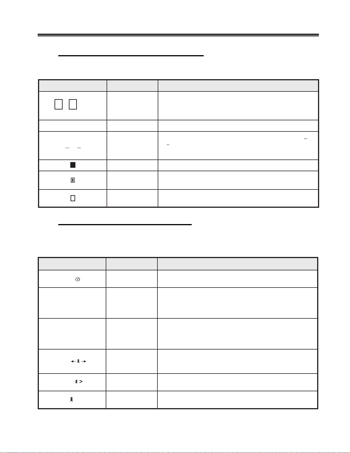
Setup Menus, Controls, and Indicators
Readiness and System Connection Symbols
These symbols are displayed either alone or in combinations to indicate the readiness
status of the display station, control unit, and system.
lobmyS emaN gninaeM
64
or S
,
ydaeRtinUlortnoC
.noitatsyalpsidehtotdetcennoc
tinUlortnoC4723MBI,4731xeleTxeromeM,4721xeleTxeromeM
;)6(tinUlortnoC6723MBIro,471xeleT,672xeleT,)4(
sitinUlortnoC4713MBIro,rellortnoCkrowteN4711CTM/XTM
iroI
roB
A
boJyM
?
denwonU
ydaeRXX34MBI
BroAenilnO
rotarepOmetsyS
(BB snoitcasnarttinulortnocdnanoitatsyalpsidnrevogselurenilnO.)
ehtnislobmysemosfogninaem.worsutatsrotarepo
.)margorp
.margorplortnocronoitacilppa
“Do Not Enter” (Input Inhibited) Symbols
The X (Do Not Enter) symbol indicates that the display station does not accept input
from the keyboard. Additional symbols are displayed to the right of the X to define why
the input is not accepted.
lobmyS emaN gninaeM
X
emiT
.noitatsyalpsidehtotdetcennocsimetsysXX34MBInA
(AselurenilnorednumetsystsohotdetcennocsitinUlortnocAAro)
ehtegnahcyamselurelbacilppafoteseht;metsystsohehthtiw
.margorpnoitacilpparuoyhtiwgnikrowsinoitatsyalpsidehT
lortnoc(rotarepometsysehtotdetcennocsinoitatsyalpsidehT
ehtottontub;metsystsohehtotdetcennocsinoitatsyalpsidehT
evahuoynoitcnufehtmrofrepotemitseriuqermetsystsohehT
.detelpmocebotnoitcnufehtroftiaW.detseuqer
yalpsidehtybdetpeccatonsawdetpmettauoynoitarepotsalehT
X?+
X SYSTEM
X
X
X
NUM
?tahW
kcoLmetsyS
.egassem
erehweslEoG
.noitarepoehttaeperdna
nahTeroM
ciremuN
.yrtne
.yrtneehttcerrocdnayek
ottnawuoynoitarepoehterusneotyalpsidehtkcehC.noitats
.yrassecenebyamseirterdetaeper,desusawyeknttAroqeRsyS
roegassemarofkooL.draobyekehtdekcolsahmetsystsohehT
ehtsesumargorptsoheht,sledomCLDSnO.yekteseRehtsserp
txenehtdnesotrotarepoehttseuqerotlobmyskcoLmetsyS
ehttcerrocdnayekteseRehtsserP.dleifsihtrofatadhcumooT
701344-003 3-41
ehtfI.noitarepoehtyrterdnayekteseRehtsserP.tcerrocsimrofrep
otoG.dleifdilavnirodetcetorpaninoitareponadetpmettaevahuoY
,rosrucehtevom,yekteseRehtsserP.noitcaekatotnoitisoprehtona
teseRehtsserP.dleifsihtnideretneebnacsretcarahcciremunylnO
Page 61
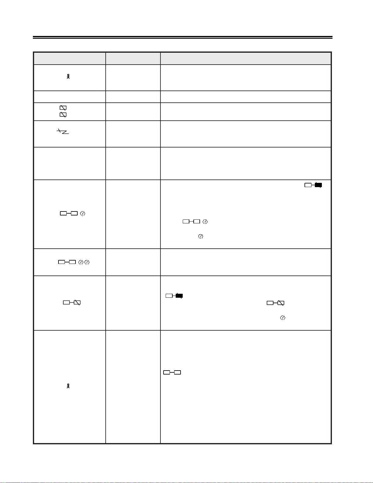
Setup Menus, Controls, and Indicators
lobmyS emaN gninaeM
X ?#
?rebmuNtahW
sihT.dleifsihtnideretneebnacsretcarahcciremunniatrecylnO
tonsirebmunDIretnirPdetcelesanehwdeyalpsidsilobmys
.yrtneehttcerrocdnayekteseRehtsserP.denifedtonsirociremun
X–f
nn
X
nnn
X
X
5nn
X PROGnnn
X
X
noitcnuFsuniM
kcehCenihcaM
noitacinummoC
kcehC
kcehCmargorP
pap .noitcaetairpor
ysuBretnirP
,
.noitcaetairporpparof7retpahCotrefer
X
.syekteseRdnatlAehtgnisserp
ysuByreVretnirP
.hsinifotemit
.yekteseRehtsserP.elbaliavanusinoitcnufdetseuqerehT
otyekteseRehtsserP.ylreporpgnitarepotonsinoitatsyalpsidehT
.noitcaetairporpparof7retpahCotrefer,srucerrorreehtfI.revocer
dnatinulortnocehtneewtebenilsnoitacinummocehthtiwmelborpA
,srucerrorreehtfI.revocerotyekteseRehtsserP.metsystsoheht
.metsystsohmorfatadnirorregnimmargorpdetcetedtinulortnoC
gnorwehtebyamesunimargorpnoitacilppaehT.yekteseRsserP
rof7retpahCotrefer,stsisrepmelborpfI.noitatsyalpsidehtrofeno
fI.ysubsinoitatsyalpsidehtotdengissaretnirpxaocehT
nacuoy,ssecorpnisignitnirpehtelihwthgirehtnodeyalpsidsi
tnirpgnidnepehtlecnacrohsinifotnoitarepoehtroftiawrehtie
sahtifitseuqerehtslecnacsihT.yektiuQehtgnisserpybnoitarepo
,detratssahtifibojehtforedniamerehtslecnacrodetratston
tiuQehtgnisserP.draobyekehtskcolnudnasesare
sihtsecalpermetsystsohehtmorfgnitnirpsiretnirpehtelihwyek
ybnoitarepotnirptnerrucalecnactonnacuoY.htiwlobmys
lanoitiddaseriuqernoitarepotnirpehttahttpecxe,evobasaemaS
sserP.gnikrowtonsinoitatsyalpsidehtybdetcelesretnirpxaocehT
fI.tseuqertnirpehtlecnacdnadraobyekehtkcolnuotyektiuQeht
nn,worsutatsrotarepoehtnodeyalpsidsiretnirpeht
X
gnikroWtoNretnirP
X
fI.noitarepotnirptsalehtgniruddeppotsa,deyalpsidsi
yektiuQehtgnisserP.ssecorpnisinoitarepodetseuqermetsystsoh
X
.setelpmoctnirpehtlitnutiawtsumuoydna
retnirpdetseuqerehtodotdezirohtuatonsinoitatsyalpsidThe
snoitidnocgniwollofehtfoenO.yekteseRehtsserP.noitcnufdetaler
otlobmyssihtdesuaca:raepp
rorebmunretnirpehtgniretnetuohtiwyektnirPehtdesserpuoY
??
XX
rotarepO
dezirohtuanU
.dengissa
ehTn rofdewollatontub,tinulortnocehtybdenifedsideretnerebmu
.tneserpsi
retnirponsahtinulortnocehtdnadesserpsawyektnedIehT
.noitatsyalpsideht
yalpsidafostnetnocehtfollatpeccaotelbanusiretnirpehT
.gnitnirplacolgnirud
3-42 701344-003
deyalpsidebotsesuacgnitnirpdetseuqermetsystsohehtrof
Page 62

Setup Menus, Controls, and Indicators
lobmyS emaN gninaeM
3
X
– S
X
X
*+?
X
kcoLytiruceS
lobmySsuniM
devieceRegasseM
dilavnI
yeK–daeD
noitanibmoC
.yekteseR
.yekteseR
Reminder Symbols
These messages are a reminder that a condition has occurred.
lobmyS emaN gninaeM
5nn
rednimeRsnoitacinummoC
,rebmunnnronnn.melborpnoitacinummocfoepytehtsetacidni,
cinortcelEehtgnisU“otrefeR.gnikrowsikcolyeKytiruceSehT
.81 -4egaPno”kcoLytiruceS
ehtsserP.tinulortnocehtybdezingocertonsidepytlobmysehT
ehtsserP.detcejerdnadeviecersawrotarepolortnocehtmorfegassemA
erehw(noitanibmocyek-retcarahc/yek-daeddilavninA*tneccanasi
,hcnerFrofderugifnocsnoitatsyalpsidno(deretnesaw)retcarahc
hcnerF/ssiwSdna,namreG/ssiwS,hcnerFnaidanaC,hsinapS
ehtretnednayekteseRroqRsySehtsserP.)ylnosnoitacilppa
.niaganoitanibmocyek-retcarahc/yek-daed
gnicudorpsiknilsnoitacinummocmetsystsoh/tinulortnocehT
rorreehT.metsysehthtiwgnitacinummoctonerauoY.srorre
Shift and Mode Symbols
These messages indicate the shift and mode the keyboard is using.
lobmyS emaN gninaeM
MUNciremuN
).etarepo
tfihspU
tresnI
tceleSdednetxE
AkcoLspaC
NnoisrevnoCecapS/lluN
ciremuNnisidraobyekehtdnanosinoitcnufkcoLciremuNehT
syekpuDdna,)-(suniM,).(doireP,9hguorht0ylnO(.edom
.edomtfihSnisidraobyekehT
ebnacretcarahcA.edomtresnInisinoitatsyalpsidehT
ybffodenrutebnacedomtresnI.noitisoprosrucehttadetresni
:syekgniwollofehtfoenognisserp
)Fro(FP,AP,retnE,qRsyS,tseT,teseR
.edomtceleSdednetxEnisinoitatsyalpsidehT
sadeyalpsiderasretcarahcdetneccadnasretcarahccitebahplA
.sretcarahcesacreppu
.nodenrutsinoitcnufnoisrevnoCecapS/lluNehT
701344-003 3-43
Page 63

Setup Menus, Controls, and Indicators
Printer Status Symbols
These messages are displayed during print operations to indicate where the operation is
performed and the progress of the print job.
lobmyS emaN gninaeM
– –
nn
retnirPxaoCngissA
tnemngissAretnirPxaoC
ehtgnisserpybdegnahcsissalC/DIretnirpxaocehtnehW
draobyekehtmorfderetnesiDIlaremun–owteht,yektnedI
.snoitisopdenilrednuehtnideyalpsidsidna
.nnretnirpxaocesuotdezirohtuasinoitatsyalpsidehT
:gniwollofehterasrebmuntnemngissaretnirpelbissoP
rebmuntropretnirplaudividni–XXhguorht10
xaocmumixameht=XXerehw
stroppusrellortnocehtrebmuntrop
rebmunssalcretnirp–58hguorht07
ehtotdehcattaretnirplacol–99
noitatsyalpsid
:etoN gnirebmunroflaunams'rotareporellortnocehttlusnoC
.58hguorht07stropxaocotdehcattasretnirpfo
nn
nn
??
gnitnirPretnirPxaoC .bojruoygnitnirpsiretnirpxaocdetcelesehT
eruliaFretnirPxaoC
.yektiuQeht
retnirPxaoCtahW
Entry Assist Indicators
lobmyS emaN gninaeM
CODedoMtnemucoD
D
noisrevnoC
parWdroW
ecapS/lluNhtiwedoMtnemucoD
.krowruoygnitnirpelihwdeliafsahretnirpxaocdetcelesehT
sserpronoitidnocehtraelcuoylitnunosniamerlobmysehT
tnedIehtsserP.degnahcsahtnemngissaretnirpxaocehT
silobmyssihT(.tnemngissaretnirpwenehtyalpsidotyek
xeleTaotdehcattasnoitatSyalpsiD3841nodeyalpsidylno
.tinUlortnoC4723MBInaro,4721xeleTxeromeMa,472
eromroF.edomtnemucoDnisinoitatsyalpsidehT
.5retpahCotrefer,noitamrofni
ecapS/lluNehtdnaedomtnemucoDnisinoitatsyalpsidehT
.nodenrutsieutaefnoisrevnoC
roF.delbanesinoitcnuf)enilwencitamotua(parWdroWehT
.5retpahCotrefer,noitamrofnierom
3-44 701344-003
Page 64

Setup Menus, Controls, and Indicators
Response Time Monitor Indicators
lobmyS emaN gninaeM
.
.
t.ss
ss:mm
epyTtrohS
epyTgnoL
dezirohtuanUyalpsiD
esnopserehtyalpsidotdewollatonsinoitatsyalpsidehT
ehtdelbanetinulortnocehthguohtla,metsystsohehtybemit
.rotinoMemiTesnopseR
dettimsnartebotatadtsalehtrofderiuqeremitehtsetacidnI
(metsystsohehtot ss dnasdnocesrof t foshtnetrof
wenalitnudeyalpsidsniamerlobmyssihT.)sdnoces
.deyalpsidsilobmysrotinoMemiTesnopseR
dettimsnartebotatadtsalehtrofderiuqeremitehtsetacidnI
(metsystsohehtot mm dnasetunimrof ss .)sdnocesrof
emiTesnopseRwenalitnudeyalpsidsniamerlobmysehT
.deyalpsidsilobmysrotinoM
???
Local Symbols
The following types of operator status row symbols are generated by a locally attached
device:
• Local Error
• Record/Play
• Device Dependent
Local Error Indicators
lobmyS emaN gninaeM
f–ecneuqeSdilavnI
?+
Pf–edoMyalPnIyeKdilavnI
delecnaCyalpsiD .delecnacsawtnemerusaememiTesnopseRtnerrucehT
tnemevoMrosruCdilavnI
yeKtegraTdilavnI
ecneuqeSyeKoN
lluFaerAdroceR
.dengissaebtonnacsekortsyekhcihwotyekadesserpuoY
.lobmysehtesareotyektcerrocasserP
aeraneercsehtfotuorosrucehtevomotdetpmettauoY
neercsehtnihtiwrosrucehtevoM.aeratnirpehtgnitteselihw
.lobmysehtraelcotaera
.dengissaebtonnacsekortsyekhcihwotyekadesserpuoY
.lobmysehtesareotyektcerrocasserP
sserP.dengissasekortsyekonsahtahtyekadesserpuoY
.lobmysehtraelcotyektcerroceht
dedrocerehtelihwdesserpsawyektiuQehtnahtrehtoyekA
ehtnehwsraeppasidlobmysehT.gniyalpererewsekortsyak
.desserpsiyektiuQehtrosetelpmocgniyalper
dedroceremoseteleD.dedrocerebnacsekortsyekeromoN
eromdrocerotredroniyekrehtonaotdengissasekortsyek
.sekortsyek
701344-003 3-45
Page 65

Setup Menus, Controls, and Indicators
lobmyS emaN gninaeM
KNdna,K,LyalpsiDlanimreTrorrE
Record/Play Symbols
These messages are displayed on the operator status row when the display station is in
Record/Play mode.
lobmyS emaN gninaeM
RdroceR
R
^
PyalP
esuaPdroceR
otrefeR.stnemelestinirorrenadetcetednoitatsyalpsidehT
.noitamrofnieromrof7retpahC
ehttarebmunehT.edomdroceRnisinoitatsyalpsidehT
.dedrocerebnactahtsekortsyekforebmunehtsetacidnithgir
ehtngissaottnawuoyhcihwotyekFProFehtsserP
.gnidrocererauoysekortsyek
ehtdnaedomdroceRgniruddesserpsawyekesuaPehT
otniagayekesuaPehtsserP.spotsyliraropmetgnidrocer
.sekortsyekgnidrocereunitnoc
otyekFProFehtsserP.edomyalPnisinoitatsyalpsidehT
.kcabyalpottnawuoysekortsyekehtdengissauoyhcihw
yalpehtlecnacotyektiuQehtroyekyalPehtsserP
.noitarepo
P
^
esuaPyalP
sutatSyeKdroceR
Device Dependent Symbols
lobmyS emaN gninaeM
evitcAxaoC .evitcasienilxaocnoitatsyalpsidehT
evitcAtoNxaoC .evitcatonsienilxaocnoitatsyalpsidehT
miDotuA
dnasnoitarepoedomyalPgniruddesserpsawyekesuaPehT
lamronmrofrepnacuoY.spotsyliraropmetkcabyalpeht
.niagayekyalPehtsserpuoylitnusnoitarepo
evah)oedivesreverni(syekhcihwswohsrotacidnisihT
.sekortsyekdengissaneebydaerla
deviecertonsahyalpsidehtrodesserpneebtonsahyekA
ehtnruterotyekynasserP.setunimdeificepsehtrofatadyna
.stnetnocyalpsid
3-46 701344-003
Page 66

Chapter 4. Operating Procedures
Before you begin to operate the 1483, ensure that the display station is attached to a
powered, operational control unit or processor. Refer to Page 1-1 for a list of
compatible control units and processors.
Preparing to Operate
After the display station has been properly installed and connected to its control unit,
it is ready to operate online. T o ensur e that the display station is prepared for operating,
perform the following procedure. If you encounter operational diff iculty or if the display
station malfunctions, refer to Chapter 7.
1) T urn the security lock ke y counterclockwise to unlock the keyboard.
2) Set the Power -On/Of f switch to On ( | ) to turn on power.
3) An alarm sounds briefly. The cursor is displayed in the upper left corner of the
screen and the operator status row displays one of the following Ready symbols:
6
•
– If attached to a Telex 276 Control Unit/Display Terminal, or IBM 3276
Control Unit Display Station.
4
•
– If attached to a Memorex Telex 1274, a Memorex Telex 1374, a Memorex
2274, or an IBM 3274 Control Unit.
• I or i – If attached to an IBM 4300 processor.
• S – If attached to a MTX/MTC 1174 Network Controller or IBM 3174 Control
Unit.
The Power-On indicator is lit.
Note: Refer to “Operator Status Row Indicators” on Page 3-40 in this manual for an
explanation of all operator status row symbols.
4) If the Power -On indicator does not light, the cursor does not appear, or a display like
the one described above is not produced, refer to Chapter 7.
If B is displayed in the first character position of the operator status row, refer to
Chapter 7.
5) Adjust the Brightness control, the Contrast control, the Vertical Centering control,
and the Horizontal Centering control, if necessary .
701344-003 4-1
Page 67

Operating Procedures
Adjusting the Screen Display
The 1483 is designed to operate with a color SVGA or V GA, or a monochrome SVGA or
VGA monitor. If the screen is not displaying correctly, or there is interference from
nearby electronic devices, you may need to change the vertical refresh rate (color) or
mode/intensity setting (monochrome) on your monitor. Follow the appropriate
procedure below .
Color Monitor
If you use a color monitor, two vertical refresh rates are possible, 72 Hz mode (the
default) and 60 Hz mode.
T o change the vertical refresh rate, turn the Po wer-On/Of f switch to Of f, then press and
hold one of the following function keys while you turn the Power-On/Of f switch to On:
F1 – Sets a color monitor to 60 Hz vertical refresh rate.
F2 – Sets a color monitor to 72 Hz vertical refresh rate.
F7 – For multifrequency monitors that can operate up to 42 KHz, sets vertical refresh
rate to 75 Hz.
Monochrome Monitor
To adjust the mode or intensity setup, turn the Power-On/Off switch to Off, then press
and hold one of the following function keys while you turn the Power-On/Of f switch to
On:
F3 – Sets the monitor to 14-inch monochrome V GA mode with “color” menus that display
varying monochrome intensities in different fields.
F4 – Sets the monitor to 14-inch monochrome V GA mode with “color” menus that display
varying monochrome intensities. This setting gives a different set of intensity defaults
than those generated by pressing F3.
F5 – Sets the monitor to 15-inch SVGA mode.
F6 – Sets the monitor to 14-inch or 15-inch monochrome with overscan (for use with
monitors that support overscan).
4-2 701344-003
Page 68

Assigning a Coax Printer
Each display station in a system configuration can be assigned a Host printer for
generating copies of information displayed on the screen. These copies can be used to
maintain records of terminal/CPU transactions.
For 104-key and 122-key ke yboards, press and hold the Alt key , then press the Ident key
to display the Assign Printer condition symbol (
For 102/103-key keyboards, press and hold the Shift key, then press the Ident key to
display the symbol.
Operating Procedures
) on the operator status row .
– –
Note: If
the
instead of Screen printer or T rimmed Print. This allows you to assign the coax
printer.
Consult your supervisor for an available coax printer’ s ID number and enter the twodigit number for the printer being assigned. The two-digit number replaces the
underscore positions on the operator status row. Once the printer’s ID number is
entered, the sequence ends automatically .
If an invalid ID number is enter ed for a Host printer, the “Wha t?” symbol (X ?+) appears
on the operator status row . If this occurs, press the Reset key and try another number.
99
appears on the operator status row when the Ident key is pressed,
– –
Data Entry Function
The data entry function consists of writing data messages in an acceptable form for
computer processing. As you enter messages through the ke yboar d, they are displayed
on the screen either as unformatted information or according to a program determined
format. Attributes of the formatted display screen fields control the amount and type
(alphanumeric or numeric) of entered data.
Figure 4-1 on Page 4-4 shows a typical formatted display screen. All fields on the
screen are preceded by a nondisplayed attribute character and are defined as
protected or unprotected (entry) fields. For protected fields, the application program
fills in the information following the attribute characters. Attempts to change
displayed information in a protected field cause a “Go Elsewhere” condition symbol
X
(
fields accept new or revised information from the operator. Some application
programs further designate an entry field by displaying the cursor in the unprotected
field’s first character position.
) to be displayed on the operator status row. The unprotected (or entry)
will not display. Enter Setup mode and select Host printer
701344-003 4-3
Page 69

Operating Procedures
Protected Field Cursor
ORDER #
+
NAME
+
PART #
+
Numeric Field
Attribute Character
(not displayed)
+
+
ABC CO 314
705163–12
+
Unprotected Field (Entry)
Mark Unprotected Block Selected
Alphanumeric Field
Figure 4-1. Typical Formatted Screen
Unprotected fields are classified as either alphanumeric or numeric. Alphanumeric
fields can accommodate both alphabetic and numeric data characters. Numeric fields
are controlled by the application program so that attempts to enter characters other
than digits 0 through 9, a period, a Dup key, or a minus sign result in an error. On
international keyboards, the comma can be entered instead of the period. The display
station with a Data Entry keyboard automatically shifts into Numeric mode whenev er
the cursor enters a numeric field.
Data characters in unprotected fields also can be displayed as intensified (brighter) fields.
In applications requiring the use of confidential information, both the protected and
unprotected fields can be programmed to be nondisplayed fields.
Note: Use of nondisplayed fields precludes visual verif ication of entered data before
transmission to the CPU.
Before you can begin to enter data characters, the display station must access the CPU
and its application program. Access is usually achie ved by using the Attention, Program
Access (P A), Function (F), Clear, or Enter k ey , or through a series of sign-on commands
and programmed CPU responses. This series is initiated when the display station comes
online. Contact your supervisor or refer to a system user’ s guide for appropriate program
accessing procedures.
Keyboard Operations
The description of keystroke functions and operations initiated from the keyboard in this
section applies to display stations with 102/103-key, 104-key, or 122-key keyboards
attached. If symbols are different from keyboard to keyboard, all are illustrated in the
text. The symbols for each function can be found on the ke yboard attached to the display .
Remember that legends that appear on the key face are Alt functions and legends that
appear on the key top can be shifted or nonshifted functions as illustrated in Figure 3-1
on Page 3-3.
4-4 701344-003
Page 70

Moving the Cursor
The cursor always indicates the next available character position on the screen. For
applications using an unformatted display screen, select the location for the next character
to be entered by moving the cursor to the selected screen position. The following ke ys
are used for positioning the cursor:
Operating Procedures
Press the Up Arr o w key (
Press the Down Arro w ke y (
Press the Left Arro w key (
depression.
Press and hold the Alt and Left Arro w keys (
at a time. When the cursor mov es beyond the edge of the screen, it “wraps” or reappears
at the last character position of the previous line.
Press the Right Ar row key (
each depression.
Press and hold the Alt and Right Arro w keys (
at a time. When the cursor mov es beyond the edge of the screen, it “wraps” or reappears
at the first character position of the next line.
Press the New Line key (
line. When the cursor is at the last entry position on the bottom line of the screen, pressing
the New Line key mov es the cursor to the fir st entry position at the top of the screen.
Press the Backspace key (
) to move the cursor up on the screen.
) to move the cursor down on the screen.
) to move the cursor horizontally left one position for each
) to move the cursor left two positions
) to move the cursor horizontally right one position for
) to move the cursor right two positions
) to move the cursor to the first entry position on the next
) to move the cursor backward.
Press the Home key to move the cursor to the first available character position on the
screen (Home on 102/103-key keyboard, and
If the application uses a formatted display screen, the following three additional keys
can be used to position the cursor:
Press the T ab key (
entry field.
Press the Backtab key (
current or preceding entry field.
Press the Skip key (Data Entry keyboards only) to move the cursor to the first entry
position in a subsequent entry field.
For applications using unformatted display screens, pressing the Tab, Backtab, or Skip
key returns the cursor to the first av ailable character position on the screen.
) to move the cursor forward to the first entry position of the ne xt
) to move the cursor back to the first entry position in the
on 104/122-key keyboards).
701344-003 4-5
Page 71

Operating Procedures
Entering Data Characters and Selecting Modes
Alphabetic, numeric, and special characters can be entered by pressing their corresponding
keys.
After filling the last data line of the display screen, the cursor automatically returns to
the first available character position, and entry of additional data may write over any
previously entered characters. To prevent loss of previous entries, transmit the data
message to the CPU whenever the screen has been completely filled with data. Refer to
“Message Transmitting Function” on P age 4-10.
Uppercase characters or the upper characters on dual character keys are entered by
selecting the Shift or Numeric mode before pressing the key . On Data Entry keyboards,
you can enter alphabetic characters in numeric fields by using the Shift (
Alpha (
Shift Mode
Hold the Shift key ( ) down while entering data to select upper characters on dual
character keys or uppercase characters for alphabetic keys, or press and release to turn
off the Shift Lock feature for keyboards with type writer layouts.
) keys (see “Numeric Lock Mode, ” belo w).
) and
Shift mode is designated on the operator status row by the
Press the Shift Lock key (
keyboards, press either Shift key to unlock. For Da ta Entry keyboards, press the Shift
Lock key again to exit Shift mode. For 102/103-key k eyboards, use the Caps Lock key
in place of the Shift Lock key . In Shift Lock mode, for 122-key , and 104-k ey , keyboards,
all keys are shifted. For 102/103-key keyboards, only the alphabetic keys are shifted.
) to lock the keyboard into Shift mode. For Typewriter
symbol.
Numeric Lock Mode
Numeric Lock mode is set or reset on the Offline Keyboard menu (Figure 3-6 on
Page 3-12). When Numeric Lock is turned on, fields accept only the digits 0 through 9,
the Period (.), Minus (-), and Dup keys (and comma [,] on some international keyboards).
When the cursor enters a numeric field, the NUM symbol is displayed on the operator
status row, and only the permitted characters can be entered. If you attempt to enter
nonnumeric characters in a numeric field, the keyboard locks. Locking the keyboard
turns off the Ke yboard clicker if it was on, and turns on the Keyboard clic ker if it was off.
Press the Reset key to restore normal operation.
On T ypewriter k eyboards, the display station goes into lowercase mode when the cursor
enters a numeric field. On Data Entry keyboards, the display station goes into uppercase
mode when the cursor enters a numeric field.
Nonnumeric characters can be entered in numeric fields by the following methods:
For Data Entry keyboards and Typewriter keyboards, press the Shift key (
uppercase characters in a numeric field.
) to enter
For Data Entry keyboards only , press the Alpha key ( ) to enter any lowercase character
in a numeric field.
4-6 701344-003
Page 72

The Shift Lock key does not override the Numeric Lock feature.
Keystroke Record/Playback
The Keystroke Record/Playback function enables you to reduce the number of
keystrokes required for a frequently repeated entry such as a logon sequence or an address.
Keystroke sequences can be stored for each of the Function keys. The combined total
of stored keystrokes cannot exceed 7000 and the Shift key and Alt ke y each count as two
keystrokes. The entered keystroke sequences are stored in nonvolatile memory, which
means that the data is retained even if the power is turned of f.
Calculator keystrokes can be recorded with the Record/Playback feature. Entering
Calculator mode, importing data, doing calculations, exporting data, and exiting Calculator
mode can all be recorded. The only limitation is that the status of the calculator (on or
off) to begin playback must be the same as when the record sequence was started.
Storing Keystroke Sequences
Keystroke sequences are stored by ke ying as follows:
Operating Procedures
1) Press the Record key . R, a number indicating the av ailable keystroke storage space,
and the Record key indicator are displayed on the operator status row.
2) Press an F or PF key. The selected key number is displayed on the operator status
row along with the number of keystrokes that have already been assigned to that
key, if any. The key number is displayed in high intensity. At this point, you can
press the Record key or the Quit key to exit to Online mode.
3) If keystrokes are already assigned to this key, you can clear them by pressing the
Delete key (
not want to delete the previously assigned sequence, press Record and choose another
Function key. While you are entering keystrokes, press the Quit key to clear the
currently recorded keystrokes and exit to Normal mode.
4) Begin typing the keystrok e sequence. If the selected Function key has no ke ystrokes
previously assigned to it, the number on the status row decreases by one each time
you press a key. The number decreases by two every time you press a Shift or Alt
key.
To record a .25-second pause after a keystroke, press the Record Wait key. The
Record Wait key is only on the 122-key keyboard. It is the leftmost key on the
bottom row of the left keypad and has a blank face. Y ou can press the Record Wait
key seve ral times to increase the length of the pause.
). The keystrokes are deleted and you e xit to Online mode. If you do
701344-003 4-7
Page 73

Operating Procedures
5) If you want to stop recording keystrokes momentarily to perform other operations,
press the Alt ke y follo wed by the Pause k ey. T he symbol
operator status row . Press the P ause key again to continue recording ke ystrokes.
6) Press the Record ke y to store the sequence and exit Record mode.
Playing Keystroke Sequences
A stored sequence is automatically keyed in Playback mode by doing the following:
1) Set the cursor to the selected insertion location.
2) Press the Play key. P is displayed on the operator status row along with the total
number of recorded keys.
3) Press the Function key under which the sequence is stored. The stored characters
are keyed back at approximately fi ve characters per second. Press the Quit key during
replay to return the display terminal to Normal mode. The P is no longer displayed
on the operator status row after playback completes.
4) After you press the Pause key in Record mode, the replaying temporarily stops and
the symbol
normal operations and press the Play key to continue replaying the rest of the recorded
keystrokes.
P
R
^
is displayed on the
^
is displayed on the operator status row . You can temporarily resume
Record/Play Security Mode
When you enable this option, you cannot use the alphanumeric keys on the keyboard to
record data, If you try , the 1483 automatically exits from Record/Playback mode. It also
prevents you from playing back data recorded in the Command or Function keys. If you
press a Function key , the display station exits from Record/Playback mode.
Enabling Record Security Mode
Enable Record Security mode by selecting Play/Record Option on the System
Manager menu (Figure 7-1 on Page 7-2). Follow the instructions in “Play/Record
Option” on Page 7-7 to select a Record Security mode.
Disabling Record Security Mode
To disable Record Security mode or change from a more restrictive security level to a
less restrictive lev el, you must get a service technician to reset the selection.
4-8 701344-003
Page 74

Cursor Select Data Entry
The Cursor Select key, CrSel, can be used to select certain data fields from a
formatted screen. The application program must define selectable fields by
writ ing the appropriate attribute. These data fields are read by the application
program for additional processing.
Each selectable data field is preceded by an appropriate field attribute character and a
designator character . Designator characters precede one of two types of fields: selection
fields or attention fields. With the Cursor Select key, items in a selection field can be
selected and then the program can be notified of the selection by selecting an attention
field.
An unselected selection field is preceded by a question mark (?), which changes to a
greater than symbol ( >) when the field is selected. Attention fields are preceded by an
ampersand (&) or space. These symbols do not change when an attention field is
selected.
T o select or deselect a field, move the cursor to co ver the appropriate designator character
or any character in the field and press the Cursor Select key . The question mark preceding
the field changes to a greater than symbol after the field has been selected. If you accidentl y
select the wrong field, you can deselect it by pressing the Cursor Select key again in the
same field. The greater than symbol preceding the field changes to a question mark after
the field has been deselected.
Operating Procedures
For some programs, after you have finished selecting f ields, press the Enter key to send
the fields to the host application program for additional processing. The selected fields
also can be sent by selecting an attention field designator character using the Cursor
Select key. The ampersand and space characters designate attention fields. Move the
cursor to cover any character in the field and press the Cursor Select key to send the
attention field data along with data in any other selected field on the screen.
Exiting the Cursor Select operation depends upon the program in use. Refer to a user’s
guide for your application for the proper procedure.
Data Editing Function
Y ou can change the contents of a message before you send it to the CPU, or you can call
up a previously entered message for editing.
Use the Attention, PA, F, PF, Clear, or Enter key to call up a previously entered messag e,
or use a series of sign-on commands and programmed CPU responses. The sign-on
commands are automatically initiated when the display station comes online. Contact
your supervisor or refer to a system user’s guide for appropriate recalling procedures.
All keys described in “Keyboard Operations” be ginning on Page 4-4 can be used to edit
data messages. In addition, the following keys can be used to add or delete information:
Press the Insert key to enter Insert mode for adding characters at the cursor’s current
position. Press Reset to exit Insert mode. The symbol
status row to indicate the display station is in Insert mode.
is displayed on the operator
701344-003 4-9
Page 75

Operating Procedures
Press the Delete key ( ) (Delete on 102/103-k ey keyboard) to remove a character at the
cursor’s current position. The remainder of the line shifts one character position to the
left.
Press the Alt ke y and the Delete W o rd key (
delete a word beginning at the current cursor position. This key combination is functional
only if the control unit to which the display station is attached supports the Entry Assist
feature.
Press the Erase to End of Field key, Erase EOF (ErEOF for 122-key and 102/103-key
keyboards), to erase all entry field positions from the cursor’ s current position to the end
of field. The cursor does not mov e from its current position.
Press the Alt and Er Inp k eys to erase all entry f ield positions and to mov e the cursor to
the first available character position.
Press the Shift key (
to repeat entered data and to move the cursor to the first entry position of the subsequent
entry field.
Press the Shift key (
keyboards) to enter a character that marks the end of an input field.
) and Dup key (Dup key only on 122-ke y Data Entry keyboards)
) and Field Mark key (Field Mark key only on 122-ke y Data Entry
Message T ransmitting Function
After you have filled all character positions on the screen, send the displayed information
to the CPU before you continue to enter data. When a data character is entered in the
next-to-last character position on the screen, the audible alarm sounds to remind you that
the cursor is near the end of the screen. If you continue to enter new data, the cursor
“wraps” and reappears in the first availa ble character position of the screen. Subsequently
entered characters replace displayed characters, resulting in loss of previous entries.
) (DelWd on 102/103-key keyboard) to
After filling all required character positions on the screen, press the Enter key to request
a communications line for sending displayed data to the CPU.
Press the Clear key to erase all displayed data on the screen, return the cursor to the first
available character position, and signal the CPU that a “clear” operation has occurred.
The application program in use determines specific functions of the Program Access
(PA) and Function (F or PF) keys. Contact your supervisor or refer to a system user’s
guide for further information regarding these keys.
The display station also can be used to send system request messages to the
CPU, depending on the online rules condition symbol that is displayed on the
operator status row.
If online rules A apply (
Rq (System Request) keys to send the CPU a message that the display station may be
malfunctioning or that a test request message is on the screen. If online rules B apply (
is displayed on the operator status row), press the Alt and Sys Rq keys to clear the
display and switch the display station between the control (or master) program and
application programs. Contact your supervisor or refer to a system user’s guide for
additional information about this key combination.
A is displayed on the operator status row), press the Alt and Sys
B
4-10 701344-003
Page 76
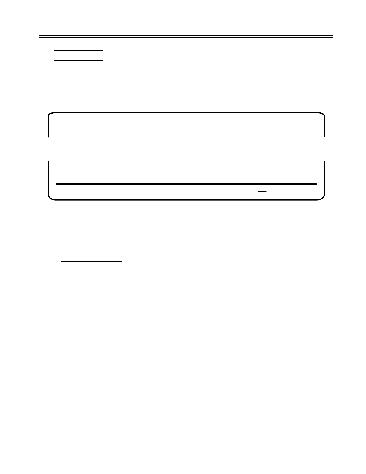
Operating Procedures
Print Function
The display station can send a print request to the host system or it can print data locally
if a local screen printer is attached. A desktop/screen printer must be ordered separately .
T o initiate host printing or local screen printing, press the Print key . The follo wing menu
is displayed on the status line:
PRINT COAX ENTER=PRINT F3=EXIT F13=Select Print F14=CTRL ,CrSel=Adjust
Figure 4-2. Online Print Menu
This menu enables you to specify the print type and to send paper control and session
control commands. Press the Enter key when you are ready to start printing.
Setting Print Type
Press F13 to toggle through the Print type options. Select one of the following:
COAX (default) – The display contents are printed on the printer attached to the control
unit.
SCREEN – The display contents are printed on the local printer attached to the display
station. For local screen printing, you can specify other print parameters, such as Print
Quality, Lines Per Inch, Lines Per Page, and Characters P er Inch. (See the Online
Printer menu, Figure 3-14 on Page 3-31.)
TRIMMED – A portion of the display contents is printed on the local printer a ttached to
the display station (Partial Screen Print). Specify the portion of the screen to be printed
by following the steps below.
As you toggle, the options are displayed on the status line next to PRINT; for example,
PRINT COAX, PRINT SCRN, PRINT TRIM.
701344-003 4-11
Page 77

Operating Procedures
If you select the PRINT TRIM option, the screen is displayed with a box around the
printable area or the last print area defined with this option. T o change the size of the trim
area, follow these steps:
1) Press the CrSel key to mov e the cursor to the upper left (or lower right) corner of the
area you want to define.
2) Press the arrow keys to move the cursor and the box corner where you want them.
The box corner moves with the cursor .
Note: The new upper left and lower right corner ro w/column settings are displayed in
the Trimmed Print Corners field of the Online Printer menu as described on
Page 3-34.
You can select a location on the printed page for the trim area output by specifying a
Print Position option on the Online Printer menu (Figure 3-14 on Page 3- 31).
Press F14 if you want to set paper control or session control options. The menu shown in
Figure 4-3, below , is displayed.
Use the arrow keys to select Paper Control or Session Contr ol.
Paper Control
The paper control options let you send a line feed or form feed command to the printer .
T o send a command, highlight Line F eed or Form Feed and press the Enter key.
Printer/Session Screen Menu Screen
Paper Control Session Control
Line Feed
Form Feed
Use Arrow Keys to select
Use ENTER Key to execute
RESET Key Exits
Figure 4-3. Paper Control Options Menu
4-12 701344-003
Page 78

Operating Procedures
Session Control
Select Session Control by using the arro w ke ys to highlight Session Control on the
Paper Control Options menu. The Session Control Options menu is displayed (Figure
4-4, below).
The session control options let you cancel the host print job (LU1 only) or, if you are
executing an LU1 print, let you send a PA1 or PA2 command to the SN A host.
Note: To cancel a local print, press the Device Cancel ke y or the Quit key.
T o select a Session Control option, move the highlight to the option you want to e xecute
and press the Enter key .
Press the Reset key to exit from the Printer Control Options menu or the Session Contr ol
Options menu. You return to the Online Print menu (Figure 4-2 on Page 4-11).
Printer/Session Screen Menu Screen
Paper Control Session Control
Use Arrow Keys to select
Use ENTER Key to execute
RESET Key Exits
Figure 4-4. Session Control Options Menu
Printing
Press the Enter key to send the print request.
Exiting from the Online Print Menu
Cancel Print
PA1
PA2
Press F3 or PF3 to exit from the Online Print menu and return to normal online operations.
701344-003 4-13
Page 79

Operating Procedures
Partitioning
The Partitioning function is a controlled function. T o use the Partitioning function, y our
display station must be attached to a controller that supports partitioning. The display
receives partitioning commands from the host only while in Nati ve mode.
T o scroll vertically through data in the viewport during partitioning, the Back and Fwd
(Forward) keys are used in the following manner:
T o scroll forward vertically (down through the data in the presentation space), press and
hold the Alt and Fwd k eys. This mo ves the data up the vie wport.
T o scroll backward vertically (up to the beginning of the data in the presenta tion space),
press and hold the Alt and Back ke ys. This action pushes the data do wn the viewport.
Extended Select Function
T o perform the Entry Assist and Response T ime Monitor functions, press the Extended
Select (ExSel) key while the display station is in Native mode. The display station must
be attached to a properly configured Memorex Telex 1274 Control Unit at firmware
release 11.0 or higher, a MTX/MTC 1174 Network Controller, or any other properly
configured controller that supports Extended Select.
Extended Select Keyboard Overlays
Exsel
Doc
On/Off
Wrap
Note: On the 122-key keyboard, to enter APL mode, press the ExSel key, then press
Chg
Fmt
Figure 4-5. Extended Select Overlay
(104-Key and 122-Key K eyboards)
the F8 key .
RTM
4-14 701344-003
Page 80

Operating Procedures
Doc
On/Off
Wrap
Chg
Fmt
Entry Assist
The Entry Assist function facilita tes the creation and editing of text such as memos,
letters, and documents. For more information on the Entry Assist function, see
Chapter 5, “Entry Assist. ”
In order to use the Entry Assist function, the control unit to which the display station
attaches must provide Entry Assist support. Consult the control unit operator’s manual
for additional Entry Assist specifications and operating procedures.
Response Time Monitor
The Response Time Monitor (RTM) records the speed of communication between the
devices attached to a valid, properly configured control unit (Memorex Telex 1274 or
IBM 3274) and the host CPU with which they are attached. The RTM is accessed and
exited by pressing the ExSel key, followed by the F19 key (122-key or 104-key
keyboards). Consult the control unit operator’s manual for additional specifications and
operating procedures.
Rtm
Figure 4-6. Extended Select Overlay
(102-Key Keyboards)
Keyboard Switch Settings
The keyboard switches are set at the factory according to the keyboard ordered. You
should not need to change them. If the settings are inadvertently changed, set them
according to the table on Page 4-16. If needed, use a pointed instrument to gently change
the settings.
Some keyboards do not have access to the keyboard switches. If you have this kind of
keyboard, you can set the switches through key sequences. See “Setting the Keyboard
Switches through Key Sequences” on Pa ge 4-16 for the key sequences.
701344-003 4-15
Page 81

Operating Procedures
yeK-221/401/301/201hctiwSDI
draobyeK
hsilgnESU
namreG/nairtsuA
naigleB
)hcnerF(naidanaC
hsinaD
ytrezAhcnerF
nailatI
naigewroN
eseugutroP
hsinapSweN
gnikaepShsinapS
hsidewS/hsinniF
namreGssiwS
hcnerFssiwS
hsilgnEKU
hctuD
sgnitteShctiwSdraobyeK3841NO=OdnaFFO=|
hctiwSDIhctiwSnoitpO
123456789 011121
|||||O
|||||O
|||||O
|||||O
|||||O
|||||O
|||||O
|||||O
|||||O
|||||O
|||||O
|||||O
|||||O
|||||O
|||||O
|||||O
||| | |
||| |O
|||O|
||O| |
||O|O
||OO|
|O | | O
|OO | |
|OO | O
|OOO |
|OOOO
O| | | |
O| | | O
O| |O |
O| |OO
O|O| |
draobyeKyeK-401
draobyeKyeK-221/301/201
O
|
Setting the Keyboard Switches through Key Sequences
T o set the ke yboard switches through ke y sequences, follow these steps:
1) Press the left Alt, Reset, and Caps Lock keys at the same time. You enter ID Set
mode with all switches set to Off (indicated by I in the table above).
2) Function keys 1 through 12 correspond to positions 1 through 12. Referring to the
table above, for each position that you want to set On, press the corresponding function
key.
For example, to set Switch 6 On, press F6.
4) When the ID is set, press the left Alt, Reset, and Caps Lock keys at the same time to
leave ID Set mode and sav e the switch settings.
If you press the wrong function key while in ID Set mode, you must leav e ID Set mode,
enter ID Set mode again (this resets all the switches to Off), and press the correct function
key .
4-16 701344-003
Page 82

Display Indicators
Power-On
When lit, the Logic element Power-On indicator indicates that the Logic element is
powered on and the Display element Power -On indicator indicates that the Display element
is powered on.
Cursor
After the display station has been powered on and has completed its warm-up period, if
it is attached to a controller with an inactive host, the cursor is displayed in the upper left
corner of the screen. If the host is active, the cursor is positioned as specif ied by the host.
When you enter data characters through the keyboard, the cursor moves to the next
available screen character position.
Using the Light Pen to Select Data
Operating Procedures
Y ou can use the optional light pen to select data from f ields that are defined for light pen
operations. Ask your supervisor to tell y ou which fields on the screens you use are set up
for light pen selection.
Do the following to select an item with the light pen:
• Press the light pen to the screen on the field you want to select.
• If you’v e turned on the Light Pen clicker, a click sounds when the field is selected.
• If the field is preceded by ?, the ? changes to > when the field is selected.
• If the field is preceded by &, processing begins as soon as you select the item.
If necessary , complete the selection by pressing a keyboar d key (for example, Enter) or
perform an additional light pen selection (like pointing to an End command).
701344-003 4-17
Page 83

Operating Procedures
Using the Electronic Security Lock
To invoke the secure (locked) mode, the operator enters the Lock sequence (Right Alt
key , Right Shift key , and Enter key). The control unit displays
the display adds a 3 to act as a prompt for a user-definable three-key passw ord to “unlock”
the display . T o unlock, type in the three-k ey password. Each key decrements the prompt
number. If the password does not match, the 3 redisplays on the status line. When the
password matches, the display is unlocked and the control unit removes the
Powering off the display while locked means it will be locked when powered on next
time. Upon power-on 3 is displayed, requiring all three password ke ys to be entered
to unlock the display. T o change the password, see “Changing the Ke yless Password” on
Page 3-14.
If the Dim Timer is not “of f, ” and the keyless passw ord is not “off” when the Dim T imer
expires, the display station locks. Pressing the space bar once and entering the password
“unlocks” the display.
on the status line and
symbol.
4-18 701344-003
Page 84

Chapter 5. Entry Assist
The Entry Assist function enhances data entry, f ormatting, and editing on the 1483. Access
to the Entry Assist function with the 104-key, and 122-key keyboards is achieved by
pressing the ExSel key , followed by the F13 or PF13 (Document-On/Off) k ey . For displays
attached to 102/103-key keyboards, press the Alt key and the ExSel key followed by
the F1 or PF1 key. Extended Select mode is entered when the ExSel key is pressed. In
Extended Select mode, the following keys become redefined to perform the Extended
Select functions.
Note: Entry Assist is a controller feature, available only if the 1483 is attached to a
controller that supports Entry Assist capability .
104-Key and 122-Key* Keyboards
DOC On/Off F13 (in Exte nded Sel ect Mod e)
Word Wrap On/Off F14 (in Extended Select Mode)
Change Format F15 (in Extended Select Mode)
Delete Word (while pressing Alt key)
Next Word (while pressing Alt key)
Previous Word (while pressing Alt key)
102/103-Key Keyboards
DOC On/Off F1 (in extend ed Select Mode )
Word Wrap On/Off F2 (in extend ed Select Mode)
Change Format F3 (in exte nded Select Mode)
Delete Word DelWd (while pressing Alt key)
Next Word (while pressing Alt key)
Previous Word (while pressing Alt key)
* The Entry Assist ke ys sho wn in the table are not valid if the 122-k ey k eyboard is set
to emulate an 88-key keyboard. To change the keyboard setting, refer to the Offline
Keyboard menu (Figure 3-6 on Page 3-12).
701344-003 5-1
Page 85

Entry Assist
In addition to the format controls (discussed below) supported in Change Format mode,
the following functions are supported in Document mode:
• Screen margins
• Tabbing
• Audible alarm indicating the approach of the end of the line
• Word wrap automatically moving an unf inished word to the next line when the word
would extend beyond the right margin
• Autorepeat word forward and word reverse cursor movement
• Autorepeat character deletion
• Autorepeat character-deleting backspace in Insert mode
• W ord deletion
Once formats are established, further data entry takes place in Document mode with the
entry and editing functions listed above. Once text is entered, it remains in the given
format even if the format is changed la ter or the terminal is taken out of Document mode.
Entry Assist Functions
Entry Assist functions consisting of formatting controls, cursor mov ement, and editing
functions are described here for display stations with 102/103-key, 104-key, and
122-key ke yboards attached.
Entering Document Mode
To enter Document mode, press the Document mode key (F1), then press the Change
Format key (F3). A format scale is displayed at the bottom of the screen, enabling various
format parameters to be altered. Cursor movement and editing controls are given to
certain keys upon entry into Document mode. When in Document mode, the display
shows the DOC message on the status row. The DOC message disappears when the
display is taken out of Document mode.
Format Controls
Once the display is in Document mode, press the Chg Fmt key to display the format
scale. This scale is displayed at the bottom of the display screen. A rev erse video block
cursor is displayed on the format scale in the same column position as the chosen cursor
in the display area (the display cursor’s v ertical position has no effect on the format scale
cursor’s position). Refer to Figure 5-1 on Page 5-3 for an e xample of the format scale.
5-2 701344-003
Page 86

Entry Assist
First Screen Column
Left
Margin
0----+----1-<--+-_-- 2----+ - _--3----+----4----+---- 5----+----6-*-->----7----+----
Left
Margin
Area
Tab
Stop
End-of-Line
Position Signal
Entry Area
Last Screen Column
Right
Margin
Right
Margin
Area
Figure 5-1. The F ormat Scale
T o hide the format scale, pr ess the Chg Fmt key again.
Use the Cursor Left (
) and Cursor Right ( ) keys to move the format scale cursor to
the desired position. Once the format scale cursor is in position, press the appropriate
format function key . When a function key is pressed, the format scale cursor disappears
and leaves in its place the appropriate format symbol. T o make the cursor reappear , press
the Cursor Left or Cursor Right key .
All of the format parameters are saved whenev er the display exits Document mode. The
last values established for the format parameters before exiting Document mode are in
effect when the display returns to Document mode. The following format parameters
(shown with their corresponding format symbols) can be changed on the format scale:
• Left margin ( < )
• Right margin ( >)
• T ab stops ( _ )
• End-of-line signal position ( * )
• Alternate right margin type ( | )
• Format scale origin (changes the scale origin from 1 to 0 and vice versa)
Left and Right Margins
To set or move the left or right margin, move the format scale cursor to the desired
position, then press the less than symbol key ( < ) for the left margin or the greater than
symbol key ( >) for the right margin. The symbol is displayed on the format scale in the
selected position. Only one left margin and one right margin can be defined on the format
scale at a time.
701344-003 5-3
Page 87

Entry Assist
When a margin is redefined, the margin symbol is replaced by a symbol for the new
margin. Tab stops and the end-of-line signal marker are retained e ven if the y are placed
outside the new margins. If the new left mar gin is to the right of the old right margin, the
right margin is moved to its default position (the f ar right scale position). If the new right
margin is to the left of the old left margin, the left margin is moved to its def ault position
(the far left scale position). The right margin cannot be entered in the left mar gin default
position, and vice versa.
When data is entered between the margins, the cursor can be located over the left
margin column, and data can be entered in this column. However, the cursor will wrap
before it reaches the right margin column. Data cannot be entered in this column during
normal typing.
Even though a margin is def ined and the display is in Document mode, data still can be
entered to the left of the left margin or the right of the right margin. The left and right
margins are established to stop the cursor during normal data entry . The Cursor Left and
Cursor Right keys allow you to mov e the cursor beyond the margins, where data can be
entered and modified the same as between the margins.
Alternate Right Margin Type
The standard right margin remains in effect during Document mode whether the
W ord Wrap function (described on Page 5-6) is acti ve or not. Ho wev er, some typing
situations call for a margin release in which no right margin is observ ed. Setting the
alternate right margin type allows you to define a right mar gin that is in effect when
Word Wrap is on and that is ignored w hen Word Wrap is off.
When the right margin is disabled (the alternate right margin set and Word Wrap is
turned off), the right side of the screen acts as the right margin and text wraps at the
screen’s margin regardless of word di visions. When Word Wrap is turned back on, the
right margin previously in ef fect is reinstated.
To give an existing right margin the alternate right margin attribute, place the format
scale cursor over the right margin symbol, then press the Cursr Sel k ey . The greater than
symbol ( >) turns into a broken vertical bar ( ¦ ) indicating that the right margin is released
when the W ord Wrap function is turned off. T o restore the standar d right margin, place
the cursor over the broken vertical bar and press Cursr Sel again. The greater than symbol
returns to the format scale.
Tab Stops
Setting tab stops on the format scale allows the tab keys to function as they do on a
typewriter, treating the defined column positions as tab stops. Once they are set, tab
stops are used in Document mode by pressing the Forward Tab (
Tab (
) key to move the cursor to the ne xt tab stop to the right or left.
) or Reverse
5-4 701344-003
Page 88

T ab stops are set by placing the format scale cursor in the desired position, then pressin g
the Forward Tab key. The format scale displays an underscore ( _ ) in the new tab stop
position unless a margin symbol or end-of-line signal symbol is in the selected position.
Even if the tab stop symbol cannot be displayed in a position, the tab function is still in
effect.
Up to 20 tab stops can be defined in any position on the format scale. Attempts to enter
more than 20 tab stops are ignored.
T o clear a tab stop, place the format scale cursor on the tab stop symbol in question, then
press the Delete Character key (
press the Clear key . All tab stop symbols are remov ed from the format scale.
). T o clear all tab stops from the format scale at once,
End-of-Line Signal
For the end-of-line signal to work, the audible alarm feature must function. When the
end-of-line signal is set, the display sounds the audible alarm as the cursor enters the
selected column position. This function can be used to warn of the approach of the right
margin, like the right bell on a typewriter.
To set the end-of-line signal, place the format scale cursor in the desired position, then
press the Asterisk k ey (*). An asterisk is displayed in the selected position. The end-ofline signal function is then enabled and remains in effect during Document mode until
the asterisk is removed.
Entry Assist
T o disa ble the end-of-line signal function, place the cursor ov er the asterisk, then press
the Delete Character key ( ). The asterisk disappears and the function is disabled. If a
tab stop is located at the end-of-line signal position, removing the asterisk also removes
the tab stop.
The Format Scale Origin
The format scale numbers can be shifted so that the scale begins with Position 1 instead
of Position 0. Tab stops, margins, and end-of-line signal positions are not shifted with
respect to the screen when the scale numbers are shifted.
T o change the scale origin, place the format scale cursor at the leftmost position on the
scale, then press the CrSel key . The numbers on the line are shifted one space to the left.
Pressing CrSel again returns the origin to 0.
Cursor Movement and Editing Functions
Cursor movement and editing functions are active whene ver the display is in Document
mode. These functions are subject to the limitations imposed by the format parameters
currently set on the format scale.
Cursor movement and editing functions av ailable in Document mode are the following:
• W ord wrap.
• Autorepeat cursor movement to next word.
• Autorepeat cursor movement to previous word.
701344-003 5-5
Page 89

Entry Assist
• Delete word to the right.
• Autorepeat deletion of character to the right.
• T ab function inserting space characters.
• Backtab function.
• Backspacing with deletion.
• New line function observing left margin.
Wor d Wrap
The Word Wrap function is turned on and off in Document mode by pressing the F2
(W ord Wrap) key . This parameter , like other format parameters, is saved when the display
is removed from Document mode and returns to its last state when the display returns to
Document mode. The W ord Wrap symbol (
When the function is on, text entry is subject to word wrapping between the left and right
margins.
W ord wrapping occurs when a word being entered would extend beyond the right mar gin.
When the character is entered that would go beyond the right margin, the entire word is
moved down one line and to the left margin. If a space is entered in the position one
character left of the right margin, the cursor is moved to the left mar gin of the next line
without word wrapping. If the cursor is one space left of the right margin and the Dup
key is pressed, the Dup character appears on the right margin and the Dup function
works as defined outside of Document mode.
) indicates that word wrapping is in effect.
The positions previously occupied by the first part of the word are replaced by space
characters. When a word is wrapped to the left margin of the next line, any null characters
to the left of the left margin are changed to space characters to preserve the format when
it is sent to the host CPU.
Word wrapping does not occur unless the entire row onto which the word is wrapped
contains only nulls or spaces. In some cases word wrapping cannot occur . In these cases,
input is inhibited and the status row shows the Too Much symbol (
Reset key for additional entry . The follo wing conditions prevent wo rd wrapping:
X
). Press the
• The word takes up the entire length of the line.
• There is already text on the next line.
• The current line is the last line on the screen.
• The next line begins with a protected field.
5-6 701344-003
Page 90

If the display is in Insert mode and a word is inserted on a line, any word pushed beyond
the right margin may be wrapped to the next line if the next line contains enough spaces
after its last word or its margins contain enough nulls to make room for the wrapped
word. If the word cannot be wrapped onto the next line, input is inhibited and the Too
Much symbol is displayed on the status row .
Move Cursor to Next Word (Autorepeat)
To move the cursor to the next word, press and hold the Alt key, then press the Cursor
Right key (
in a word at the end of a line, to the first space or null character following the current
word. The cursor does not move into protected f ields with this function.
The cursor is moved to the next w ord regardless of the location of the margins. If text is
located outside the margins, the cursor moves to the text without recognizing the margins.
The cursor wraps to the next row only when there are no more words in the current row .
When the last word is reached on the last row , the cursor is wrapped to the first w ord on
the first row of the display.
Continuing to hold down the Alt and Cursor Right keys causes the function to repeat
automatically.
). The cursor moves to the first character in the ne xt word, or, if currently
Entry Assist
Move Cursor to Previous Word (Autorepeat)
Press and hold the Alt key, then press the Cursor Left key ( ) to mov e the cursor to
the beginning of the current word (or , if already at the beginning of a word, to the beginning
of the word to the left). If the cursor is located at the first word on a ro w , it is wrapped to
the beginning of the last word on the previous row. If at the top left position on the
screen, the cursor is wrapped to the beginning of the last word on the screen.
Continuing to hold down the Alt and Cursor Left keys causes the function to repeat
automatically.
Delete Next Word
The Delete Word key ( ) is the alternate function of the Delete Character key ( )
when the display is in Document mode. Pressing the Delete W ord key erases the character
at the cursor location and the remainder of the word to the right of the cursor. If the
cursor is on the first character of a word, the whole word is erased. If the cursor is on a
space or null, only the space or null is erased. Punctuation and spaces following a word
are also erased (unless only part of the word is erased, in which case the space or null
remains).
When a word is deleted, the cursor remains in place and subsequent data on the line
moves to the left. Shifting does not occur for attributes, characters to the right of attributes,
or subsequent lines of data. If deletion is attempted on an attribute or a protected field,
input is inhibited and the Go Elsewhere symbol (
row . Pr ess the Reset key to enable additional entry.
X
) is displayed on the status
701344-003 5-7
Page 91

Entry Assist
Cursor T abbing
Pressing the Forward Tab key ( ) causes the cursor to move to the next unprotected tab
stop. Intervening unprotected null characters are conve rted to space characters to preserve
the format when data is transmitted to the host CPU. If the cursor reaches an unprotected
attribute before it reaches a tab stop, it will stop at the attribute. If no tab stops and no
attributes are defined, the cursor mov es to the top left position on the screen.
If there are tabs or unprotected attributes on the screen, tabbing does not allo w the cursor
to wrap from the lower right corner of the screen to the upper left corner of the screen.
For some programs, the introduction of additional data (in the form of nulls being converted
into space characters) may cause problems. Programs should be verified for use with the
tab function in Entry Assist.
Backtab Function
The Cursor Backtab function works like the Forward T ab function except that the cursor
is moved to the previous tab stop or the first unprotected character of the current or
previous field. Pressing the Backtab key (
changed to spaces when a backtab operation is performed. The cursor will not wrap from
the upper left corner of the screen to the lower right corner .
) causes a backtab operation. Nulls are not
Backspacing with Deletion
Pressing the Backspace key ( ) in Insert mode deletes the character to the left of the
cursor and causes the cursor to move left one character space. Characters to the right of
the cursor on the same line are moved one character to the left. Attributes and characters
to the right of attributes are not moved.
If the cursor is located at the left margin when the Backspace key is pressed, input is
inhibited and the Go Elsewhere symbol (
the Reset key to resume entry .
X
) is displayed on the status row . Press
New Line Function
Pressing the New Line key ( ) causes the cursor to move down one line and r eturn to
the established left margin. If the left margin is protected, the cursor moves to the first
unprotected position to the right of the left margin. Unprotected null characters to the left
of the left margin are conv erted to spaces as long as there are no fields between the nulls
and the cursor.
If the cursor is on the last row of the screen and the New Line ke y is pressed, the cursor
is positioned on the first row of the screen.
If there are no unprotected locations between the margins, the cursor moves to the left
margin of the first row on the screen.
5-8 701344-003
Page 92
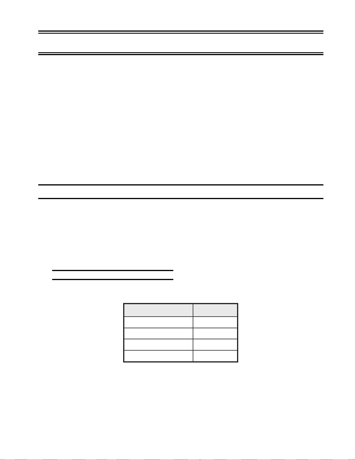
Chapter 6. Calculator Operation
The 1483 has a built-in calculator that allows you to add, subtract, multiply, and di vide
positive and nega ti v e numbers in decimal, binary, or Hex, and calculate percentages in
decimal. Computations up to 13 digits long are supported.
Calculator keystrokes can be recorded with the Record/Playback feature. See Page 4-7
for information about the Record/Playback feature.
The Decimal calculator can be selected in Calculator mode by pressing F10.
The Binary calculator can be selected in Calculator mode by pressing F2.
The Hex calculator can be selected in Calculator mode by pressing F16.
Once a specific calculator is selected, it is the calculator displayed whenever Calculator
mode is entered until changed by selection of another calculator.
Calculator Mode
T o enter or exit Calculator mode, depending on the attached keyboard, press and hold the
Alt and F12 keys (122-key and 104-key keyboards) or press and hold the Alt and F12/
F24 keys (102/103-key ke yboards).
A calculator simulation is displayed on the screen as in Figures 6-1 on Page 6-3, 6-2 on
Page 6-5, and 6-6 on Page 6-6. Use the simulation with the numeric keypad on the 122key and 102/103-key keyboards and the six ke ys immediately above the Cursor Direction
keys on all supported keyboards.
Moving the Calculator on the Screen
The following keys reposition the Decimal, Binary, and He x calculators on the screen:
yeK noitceriD
<rotfeL
¦
UpU
VnwoD
The Cursor Direction keys can be used to reposition decimal or binary calculators.
>ro)erocsrednu(_thgiR
701344-003 6-1
Page 93

Calculator Operation
Jumping Between Calculator Mode and Normal Operation
If you want to return keyboard functionality to the coax screen without losing the
calculator display, press the F12/F24 key. Make the changes to the coax screen, then
press the Alt and F12/F24 ke ys to return to Calculator mode.
Even though the 104-key keyboar d does not have a numeric keypad, you can still use the
calculator. All operations have alternative methods of entry from the main keypad as
described in the following pages.
Decimal Calculator
Use the decimal and numeric keys on the numeric keypad or the main keypad to enter
numbers for calculation.
After entering a number, enter the mathematical symbol designating the operation to be
performed. On the 104-key keyboard, you must use the main ke ypad.
+ for addition
- for subtraction
* for multiplication
÷ or / for division
If you want to enter a negative number, enter the number and then press the +/- key
indicated on the calculator simulation.
Press the = key on the calculator simulation (or on the main keypad) to display the result
of your computation in the calculator’s Results f ield.
Setting the Decimal Place
You can set from 0 through 9 decimal places on the calculator or you can choose to not
specify the number of decimal places.
If you select 0 through 9 decimal places, only the number of decimal places you select is
displayed in the Results field of the calculator. You can enter numbers for calculation
with more decimal places than can be displayed in the Results field. If the result of the
calculation has more decimal places than can be displayed in the Results field, the system
rounds off the answer before it is displayed.
You can also choose to not specify the number of decimal places. If you do not specify
the number of decimal places, the calculator displays as many decimal places as necessary
for the answer.
Note: The calculator can display a maximum of 13 digits in the Results field. If a
calculation causes a result larger than the Results field maximum of 13 digits,
the overflow symbol ? is displayed. Press C/E (Clear Entry [Clear on the
104-key ke yboards]) to continue with calculations.
6-2 701344-003
Page 94

Calculator Operation
T o set the decimal place, with the 1483 in Decimal Calculator mode, press the PF3 ke y ,
then:
T o set fr om 0 through 9 decimal places – press the 0 through 9 ke y (D0 through D9 is
displayed at the top of the Results field)
Or
To not specify the number of decimal places – press the N key.
D5
Results Field
-9.99999
XX
XMMX M + X
PF2 = BIN PF16 = HEX
PF3 = SET DEC. PLACE
Figure 6-1. Simulated Decimal Calculator
Calculating Percentages
+/-
÷%C/E
789
456
123
0
.
=
*
-
+
T o calculate a percentage of a n umber with the Decimal calculator:
1) Enter the number .
2) Press the % key indicated on the calculator simulation of the numeric keypad or the
% key on the main keypad.
3) Enter the percentage.
4) Press the = key indicated on the calculator simulation or the = key on the main
keypad.
701344-003 6-3
Page 95

Calculator Operation
The calculated percentage is displayed in the Results field of the calculator simulation.
Other Calculator Functions
Press the C/E key once to clear the current entry . Press the C/E key a second time to clear
the current total. You can also use the Clear key on the main keyboard.
Press the M + X key to add the currently displayed value to memory. M is displayed at
the bottom of the Results field to indicate that there is a number in memory .
Press the M X key to recall and display the memory contents. The memory contents
are recalled in the current Calculator mode equivalent value regardless of the mode in
which the value was saved. F or example, if 128 is saved with the Decimal calculator and
recalled with the Binary calculator, 10000000
Press the X M key to store the currently displayed value in memory . Press this key
with zero in the Results field to clear the memory .
is displayed in the Results field.
2
Press the
screen to the Results field on the calculator. The import field holds a maximum of 13
digits.
Note: The calculator interprets a comma in the import field as a European decimal
point. An y numbers to the right of the comma are treated as decimal point values
and not whole numbers (for example, 10,500 is treated as if it were 10.5).
Press the X
position on the coax screen.
Press the PF1 key to toggle the calculator simulation between full simulation display and
display of the Results field only .
X key to import the value from the current cursor position on the coax
key to export the value in the Results field to the current cursor
6-4 701344-003
Page 96

Binary Calculator
Calculator Operation
Results Field
XX
XMMX M + X
+/-
PF10 PF16
Figure 6-2. Simulated Binary Calculator
Binary Mathematical Operations
1111111000000
÷C/E
& | XOR
1
0
2
=
*
-
+
Use the numeric keys on the numeric keypad or the main keypad (1 or 0) to enter numbers
for calculation. After entering a number , enter the mathematical symbol designating the
operation to be performed. For the 104-key keyboard, you must use the main ke ypad.
+ for addition
- for subtraction
* for multiplication
÷ or / for division
X or XOR for logical XOR
! or | for logical OR
& for logical AND
If you want to enter a negative number, enter the number and then press the +/- key
indicated on the calculator simulation. Press the = key on the calculator simulation (or
on the main keypad) to display the result of your computation in the calculator’ s Results
field.
If a calculation causes a result larger than the Results field maximum of 13 digits, the
overflow symbol ? is displayed. Press C/E (Clear Entry [Clear on the 104-k ey keyboards])
to continue with calculations.
701344-003 6-5
Page 97

Calculator Operation
Other Calculator Functions
Press the C/E key once to clear the current entry. Press the C/E key again to clear the
current total. You can also use the Clear key on the main keyboard.
Press the M + X key to add the currently displayed value to memory. M is displayed at
the bottom of the Results field to indicate that there is a number in memory .
Press the M
contents are recalled in the current Calculator mode equivalent value regardless of the
mode in which the value was saved. For example, if 128 is saved with the Decimal
calculator and recalled with the Binary calculator, 10000000
Results field.
Press the X
with zero in the Results field to clear the memory .
Press the
screen to the Results field on the calculator. The import field holds a maximum of 13
digits.
Press the X
position on the coax screen.
Press the PF1 key to toggle the calculator simulation between full simulation display and
display of the Results field only .
Hex Calculator
X key to recall and display the memory contents. The memory
is displayed in the
2
M key to store the currently displayed v alue in memory. Press this k ey
X key to import the value from the current cursor position on the coax
key to export the value in the Results field to the current cursor
Results Field
A007FE
16
ABC
XMMX M + X
X
+/- C/E
X
PF2 PF10 & | X < > U V
FED
789
456
123
0
÷
=
*
-
+
Figure 6-3. Simulated Hex Calculator
6-6 701344-003
Page 98

Hex Mathematical Operations
Use the numeric keys on the numeric keypad (0 through 9) and the keys A through F to
enter numbers to be operated on. You can also use the main keypad to enter numbers
(0 through 9) and the keys A through F.
After entering a number, enter the mathematical symbol designating the operation to be
performed. For the 104-key keyboard, the main ke ypad must be used.
+ for addition
- for subtraction
* for multiplication
÷ or / for division
X (main keyboard) for logical XOR
! or | (main keyboard) for logical OR
& (main keyboard) for logical AND
If you want to enter a negative number, enter the number and then press the +/- key
indicated on the calculator simulation.
Press the = key on the calculator simulation (or on the main keypad) to display the result
of your computation in the calculator’s Results f ield.
Calculator Operation
If a calculation causes a result larger than the Results field maximum of 13 digits, the
overflow symbol ? is displayed. Press C/E (Clear Entry [Clear on the 104-k ey keyboards])
to continue with calculations.
Other Calculator Functions
Press the C/E key once to clear the current entry. Press the C/E key again to clear the
current total. You can also use the Clear key on the main keyboard.
Press the M + X key to add the currently displayed value to memory. M is displayed at
the bottom of the Results field to indicate that there is a number in memory .
Press the M
are recalled in the current Calculator mode equivalent value regardless of the mode in
which the value was saved. F or example, if 128 is saved with the Decimal calculator and
recalled with the Hex calculator , 80
Press the X
with zero in the Results field to clear the memory .
Press the
screen to the Results field on the calculator. The import field holds a maximum of 13
digits.
Press the X
position on the coax screen.
X key to recall and display the memory contents. The memory contents
is displayed in the Results field.
16
M key to store the currently displayed v alue in memory. Press this k ey
X key to import the value from the current cursor position on the coax
key to export the value in the Results field to the current cursor
Press the PF1 key to toggle the calculator simulation between full simulation display and
display of the Results field only .
701344-003 6-7
Page 99

Chapter 7. Problem Determination
and Maintenance
Diagnostic T esting Function
The 1483 Display Station can perform two types of diagnostic tests: offline tests that
check the operation of the display station independent of its attached control unit, and
online tests that check the 1483 as it interacts with the attached control unit. For purposes
of customer problem determination, some offline tests are presented in this section.
For information about online tests, refer to your controller’s user’ s guide.
Offline T ests
The display station temporarily enters Offline T est mode each time it is po wered on. The
display station’ s own series of Basic Assurance T ests (BATs) are run each time the display
station is powered on. If an error is detected, the alarm sounds and an error condition
may be displayed in row 1, column 1. K is displayed for a keyboard error and L is
displayed for a logic error .
Hold down a key while simultaneously turning on the Power-On/Off switch to enter
Offline Test mode. From Offline Test mode, you can enter Setup mode to set or change
special controls, such as the Numeric Lock and the Serial Number. Of fline Test mode is
also used to determine hardware malfunctions by running tests from the System Manager
menu. Special controls that can be set from the System Manager menu are also presented
here.
701344-003 7-1
Page 100

Problem Determination and Maintenance
System Manager Menu
T o utilize the System Manager menus, highlight System Manager Menus on the Offline
T est menu and press the Enter key . If password protection is enabled (see P age 7-5), you
are prompted to enter the password. Enter the password and press the Enter key again.
The System Manager menu is displayed (Figure 7-1, below).
These screens are for System Managers and service technicians.
Select one of the following:
Basic Assurance Tests
KBD T est
Mod size Test
Screen Centering
Password Disabled
Enter Password
Enter Serial # XXXXXXXX
Init NVRam counters 000 000
KBD Switches 10111111 10111111
Part # 220457-001
Play/Record Option Full Functions
Reset NVRam
Figure 7-1. System Manager Menu
Basic Assurance Tests
The Basic Assurance T ests selection starts a series of tests running on the display station.
The tests run in a continuous loop until you stop them by pressing the Reset key . T o start
the tests, highlight Basic Assurance Tests and press the Enter key . T o stop the continuous
tests, press the Reset key again.
7-2 701344-003
 Loading...