

Page 1

Page 2
Issued
Branch
to:
--FC>~..of4:-.
"7J//7
..
-+;
_'
~/;Ll~.(-.<·/::.
~
•
.JO:~·:::(,,;:--
______
/1
Office
:------,ts-<'t'--'7""---.~~
...
,l..-----------
_
Department:
________________
If
this
be
manual
returned
to
is
the
misplaced,
above
address,
it
should
_
frl
CjD)o
l.\I.7
~d.E)~
© 1960, 1961, 1962
by
International
Customer Engineering Instruction-Reference
1402
Business
Card Read-Punch
Machines
Corporation
Page 3
Contents
This
manual,
the
preceding
tions
have
transport,
CB
instructions
of
belt
This
manual,
and
231-0002-1.
Address
IBM,
Product
Form
Form
been
made.
and
brush
replacement
and
Form
comments
Publications
Number
231-0002-1.
Major
timing
adjustments,
and
retiming
231-0002-2
regarding
Department,
231-0002-2,
Many
revisions
procedures,
and a more
procedures.
makes
this
publication
is a major
minor
include
the
addition
obsolete
Rochester,
changes
new
complete
Forms
to:
reVISIOn
and
addi-
punch
of
solar
coverage
231-0002-0
Minnesota
of
feed,
cell
INTRODUCTION . . . . . . . . . . . . . . . . . . .
FUNCTIONAL
OPERATING
FUNCTIONAL
SPECIFICATIONS
READ
FEED.
DRIVE
READ
FILE
HOPPER
MECHANISM.
Speed.
CLUTCH.
Principles
Clutch
Clutch
Clutch
Clutch
Clutch
Clutch
FEED.
Principles
Clutch
Clutch
Service
Joggler
Principles
PRINCIPLES.
LIGHTS
SWITCHES . .
..
. . . . . . . . .
. . . . . .
. . .
of
Operation.
Adjustments.
Timing.
Pulley
Pulley
Drive
Removal.
Drive
Installation.
. . . . . . . . . . . .
of
Operation.
Adjustments.
Removal.
Checks
Adjustments.
AND
PICKER
of
Operation.
AND
CONTROLS
. . .
. . . . . .
Assembly
Assembly
. . . .
. . . . . .
. . . . . . .
KNIVES
. . . . . . .
Removal
Installation.
. .
.
. . .
.
Adjustments
CARD
CARD
BRUSH
TRANSPORT
SELECTION
TRANSPORT
JAM
BAR
STACKERS
PUNCH
FEED
DRIVE
PUNCH
GENEVA
HOPPER
CARD GUIDES
FEED
GUIDES.
Adjustments
LEVERS
Adjustments
ASSEMBLY
Adjustments
Timing
AND
Principles
Chute
Adjustment
Principles
stacker
Stacker
..........
MECHANISM
FEED
Principles
Clutch
Clutch
Clutch
Principles
Adjustments
Timing
Principles
Adjustments
Adjustments
ROLLS
Principles
Timing
Adjustments
. . . .
..
...
.
.
.....
STACKERS
MECHANISM
of
Blade
Operation
and
Selector
. . . . . . . . .
ROLL
ADJUSTMENTS
ADJUSTMENTS
...............
of
Operation.
Joggler
Adjustments
Adjustments
.......
CLUTCH
of
Operation
Adjustments. . ..
Timing.
Ratchet
. .
Removal.
.............
of
Operation.
. . . . . . . .
........
AND
PICKER
of
Operation
...........
. . . . . . . . . . . . . . . . .
AND
ALIGNER
of
Operation.
Check
of
Punch
of
Punch
....
..
..
.
.
.
.....
..
...
.
.
'
....
KNIVES
..
. . . . . .
STATIONS.
Transport.
Transport.
Magnet
....
.
. . .
.
.
.
.
.
. .
...
'.'
1-1
1-1
1-2
1-3
1-3
2-1
2-1
2-1
2-1
2-1
2-2
2-4
2-4
2-4
2-4
2-4
2-5
2-5
2-6
2-6
2-7
2-7
2-7
2-7
2-8
2-9
2-9
2-9
2-9
2-10
2-10
2-10
3-1
3-1
3-1
3-1
3-2
3-2
3-2
3-2
3-3
3-3
4-1
4-1
4-1
4-1
4-1
4-3
4-3
4-3
4-3
4-3
4-3
4-4
4-4
4-4
4-4
4-4
4-4
4-4
4-5
.
4-7
Page 4
ROLL
BRUSH
PUNCH
TIMING
DRIVE
PUNCH
PROCEDURES
Drive
CR
Timer
PCCB
Idler
PACB
Second
PLCB
Punch
First
READ
Clutched
Read
ELECTRONIC
SOLAR
Introduction
Principles
Timing
Adjustment
Removal
PERMISSIVE
Principles
Contact
CIRCUIT
Open
SERVICE
AIDS
Side
Aligner
Forward
First
Fourth
Fifth
Second
Aligner
Stepped
Upper
Upper
Stepped
OPENING
Principles
ASSEMBLIES
UNIT
......................
Principles
Punch
Unit
Punch
Unit
Cam
Follower
Cam
Follower
Cam
Follow
Interposer
Interposer
Magnet
Magnet
Magnet
Magnet
Magnet
Bar
Bar
Unit
Unit
Unit
Interposer
Interposer
Removal
Stripper
Stripper
Latch
Punch
Punching
Punch
Assembly
Assembly
Removal.
Removal
Registration.
Unit
BELTS
FEED
INSTALLATION
Main
Drive
Motor
Idler
Belt
Index
Drive
Belt
....................
Drive
Stepped
Drive
Unit
Stepped
FEED
BELT
Feed
Feed
COMPONENTS
CELL
CB
Procedure
and
MAKE
Replacement
BREAKERS
Strap
.......................
Removal
. . . . . . . . . . . . .
Removal
Feed
Roll
Feed
Roll
Feed
Roll
Removal.
Feed
DEVICE
of
Operation.
Roll
..............
................
of
Operation
Removal
.....
Installation
Bearing
Adjustments.
Assembly
Assembly
Setup
Setup
Assembly
Assembly
Timing
Bail
Adjustment
Bail
Removal
Adjustment. . ...
Removal
Adjustments
Removal
. . . . . . . .
Installation
Guide
Bar
and
Adjustment
Interposer
..............
Removal.
Installation
. . . . . . . . . . . . . .
. . . . . . . . . . . .
Timing
. . . . . . . . . . . . . . .
...................
...................
Belt
................
Belt
...............
..................
Belt.
. . . .
Belt
...............
Belt
...............
Feed
...............
Belt
Feed
Roll
............
Roll
Belt
Drive
INSTALLATION.
Roll
Belts
Drive
. . . . . . .
'"
.....
.............
. . . . . . . . .
of
Operation
..
. . . . .
Procedure.
. .
Replacement
RELAYS
of
Operation
..
..
. . . .
....
Contacts
. . . . .
. . .
..
Removal
Removal
.
Removal
...
. . . . . . . . . . .
...
.
.
...
.
Removal.
. .
.
..
. .
. . . .
.
..
. . . . . .
Link
.
. . .
. . . .
..
..
....
. . . . . . . . . . . .
..
Drive
Belt
..
Drive
Belt
...
Belt
.
.
.
.
.
.
"
.
.
.
.
.
.
.
.
.
.
.
.
.
.
.
.
.
.
.
4-9
4-9
4-9
4-9
4-9
4-10
4-10
4-10
4-10
4-10
4-10
4-12
4-12
4-12
4-12
4-13
4-13
4-14
4-14
4-14
4-14
4-14
4-14
4-15
4-15
4-15
4-15
4-15
4-16
4-16
4-17
5-1
5-1
5-1
5-1
5-1
5-1
5-1
5-1
5-3
5-3
5-3
5-3
5-3
5-4
5-4
5-4
6-1
6-1
6-1
6-1
6-2
6-3
6-3
6-3
6-3
6-4
6-4
6-5
7-1
CUSTOMER
PANEL
SPECIAL
FEATURES
51-80
Mechanical
PUNCH
Principle
Card
EARLY
SERVICE
HINTS
INSTALLATION
READ
Reader
Reader
Validity
Picker
Brush
Circuit
PUNCH
Punch
Punch
Punch
Punching
Dropping
Multiple
Damaged
PREVENTIVE
APPROACH
MAINTENANCE
PREVENTIVE
PROCEDURE
1402
CIRCUITS
POWER
CIRCUITS
READ
PUNCH
1402
MODEL 2 .,
DESCRIPTION
VARIATIONS
AND
ENGINEERING
.......................
....................
COLUMN
DEVICE.
Adjustments
FEED
READ
.................
of
Operation
Guide
CARD READ
Adjustments
.................
.......................
PROCEDURE
FEED
......................
Stop
Lights.
Check
Lights
Timing
FEED
stop
Check
Check
Lights
Knife
Breaker
.....................
................
Timing
. . . . . . . . . . . . . . . . . .
Timings
Lights.
Lights
Brushes
Registration
Punches
Punches
Cards
.....
.....
or
MAINTENANCE
TO
PREVENTIVE
...................
MAINTENANCE
.....................
........................
SUPPLY
AND
INTERLOCK
.......................
Power
On
Power
FEED
Load
start
Card
Reader
Stop
Card
Clutch
FEED
Punch
Punch
Punch
Card
Punch
Punch
Stop
Card
Clutch
Stacker
Sequence
Off
Sequence
CIRCUITS
Key
Operation
Key
Operation
Reading
Non-Process
Key
Operation
Jam
Circuits
Check
CIRCUITS
Motor
Feed
Cycles
Feed
Read
Punching
Check
Non-Process
Key
Operation.
Jam
Circuits
Check
Select
................
(RLCB
Circuit
Start
................
..................
Brushes
Circuit.
Circuits.
.......................
......................
BETWEEN
MODEL 2 ...................
Read
Feed
Roll
Punch
Emitter
Electrical
Operating
Number 4 ..........
..................
Changes.
Controls
SERVICE
. . . . . .
.....
..........
...........
. . . . . . . . . . .
..........
. . . . . . . . . . . . . .
............
Check
. . .
.....
..........
. . . . . . . . . . . . .
. . . . . . . . . . .
Out
of
Time
..
.
..
.
.
Jams
.
.......
.....
.
..............
. . . . . . . .
.....
..............
..............
Machines)
Run-Out
......
........
...............
...............
.............
...............
and
Run
.........
..............
.............
Run-Out
........
. . . . . . .
...............
. . . . . .
. .
THE
MODEL
. . . . . . .
and
Lights
1
.......
.......
....
....
7-1
.
8-1
.
8-1
.
8-1
.
8-1
.
8-1
.
8-3
8-3
.
9-1
.
9-1
.
9-1
.
9-1
9-1
.
9-1
.
9-1
.
9-1
9-1
.
9-1
.
9-1
9-2
9-2
9-2
9-2
9-2
9-2
10-1
10-1
10:"1
.
.
.
.
11-1
11-1
11-2
11-2
11-2
11-2
11-2
11-3
11-3
11-3
;
11-3
11-3
11-3
11-3
11-4
..
11-4
11-4
11-4
11-4
12-1
12-1
12-1
12-1
12-1
12-1
12-1
Page 5
ffiM
1402
Card
Read-Punch
Page 6
INTRODUCTION
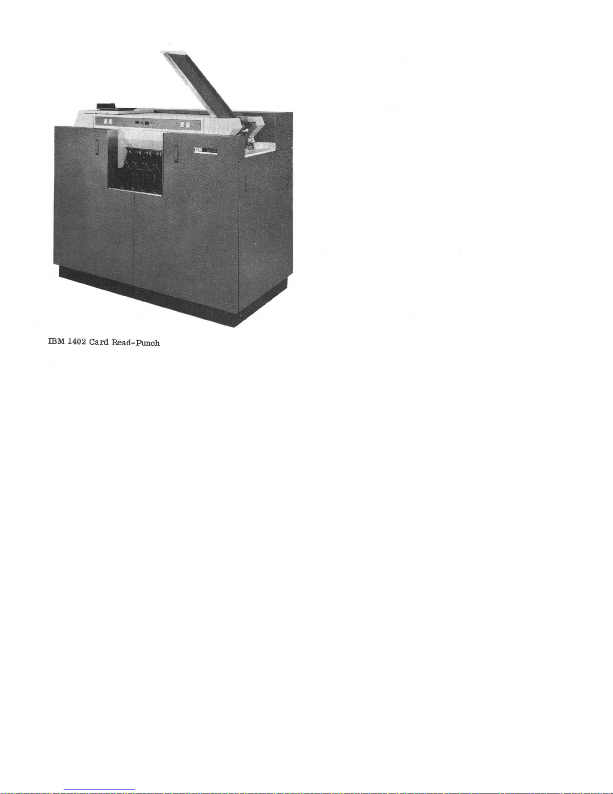
The IBM 1402
data
processing
output.
The
Card
system
read
Read-Punch
with a punch
feed
is a 20
equipped with a file feed which
cards.
of 800
cycle-point
per
plish
read
ends
read
above
driven
machine
other
The
cards
minute.
stacking
feed
of
the
feed and
the
by
noise
machines
read
feed
per
feed which
Five
radial
of
the
and
the punch feed
machine
the
punch feed
stackers.
timing
belts
and
maintenance.
of
the
can
minute.
can
stackers
cards
so
that
The
wherever
system
process
The punch
punch
into a transport
card
FUNCTIONAL PRINCIPLES
The 1402
mum
speed
feed
The
first.
feed
passes
card
in
the
where
entered
same
a hole
transported
directed
programming.
ceive
read)
directed
Card
Read-Punchcanreadcardsata
speed
is
cards
schematic
are
is
governed
of 800
cards
by
the
equipped with a 3600
are
fed
through
face
down. The
diagram
the
read
check
read
to
condition
1401.
time
again
into
count
to
It
is
80
columns
the
read
the
check
check
past
the
the
appropriate
then
may
stacker
Three
cards
stacker
from
is
to
stacker 1 or
PUNCH
the
used
PUNCH
READ
per
program
card
card
path
(Figure
brushes.
the
moved
of
area
of
planes
be
completed.
selection
stacker
stackers
read
feed. The NR
unless
the
stacker 2 (8/2).
FEED
FEED
STATtON
provides
card
cycle-point
has a capacity
cards
cards
at
are
used
from
both
are
located
cards
are
fed
transport
possible
Power
are
located
minute.
routing.
capacity
the
read
feed.
is
illustrated
1-1).
80
columns
hole
count
check
past
the
read
the
card
are
core
storage.
are
conditioned
station
under
are
available
cards
are
the
input
of 3600
at a speed
feed
is
250
cards
to
accom-
feeds.
at
opposite
from
assembly
system
to
reduce
supplies
in
the
1402.
maxi-
Actual
The
file
feed.
9 edge
in
As
the
of
planes
brushes
read
At
so
Next.
and
control
to
(normal
program-
1401
and
feed
a 16
The
the
is
for
card
read
the
card
the
and
the
that
it
is
is
of
re-
TRANSPORT
The
1402
check
card
per
minute.
pacity
is
1-1).
into
PFR
aligned
hopper.
illustrated
(optional
the
is
As
feature).
read
called
at
horizontally
Punching
the
card
passes
in
the
1401 which allows
information
storage.
At
conditioned
formed.
80
column
plane
pleted.
station
under
to
receive
Punch)
directed
stacker
and
cores
program
read
The
After
It
and
stacker
to
cannot
feeds.
card
punch feed
rolls
along
for
the
read
chute
blades
in
the
transport
jam
and
stops
(Figure
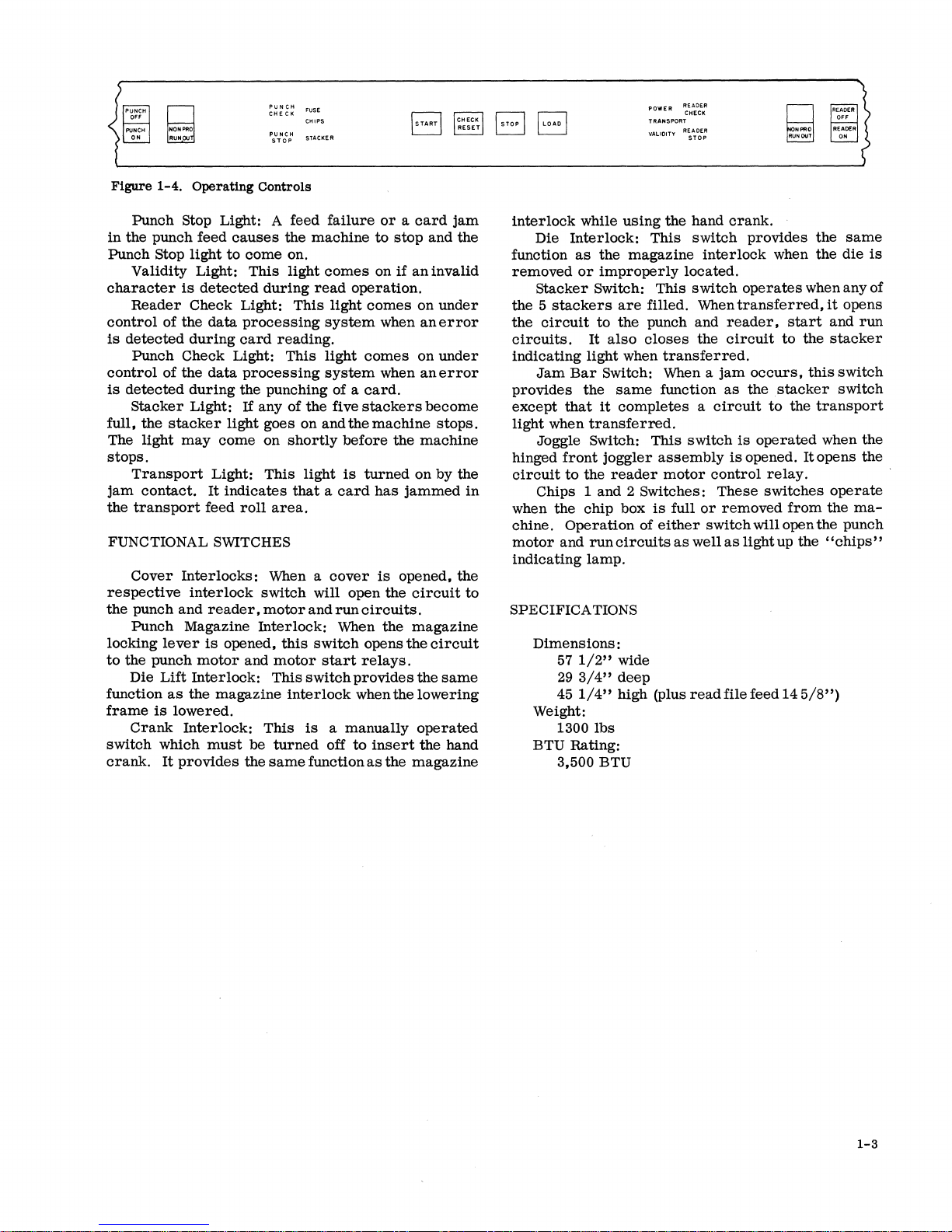
type
Cards
All
stackers
stackers
can
1-2).
Card
Read-Punch
punching
Cards
at a maximum
are
12 edge
in
the feed
the
card
80
areas
for.
Before
the
aligner
to
insure
is
done by a
the
punch
contained
the
same
so
that
a hole
the
card
punch-check
so
that
a hole
is
then
moved
is
directed
control.
cards
from
is
used
stacker 4 or
be
used
transport
and
the
read
with two
feed
for
select
as
the
punchfeed. A jam
assembly
the
machine
are
with a
be
removed
READ
placed
first.
face down.
schematic
passes
the
columns
of
core
storage
the
card
station
correct
punching
high-speed
station.
the
card
in
the
time
the
check
count
is
punched.
brushes
count
past
the
to
the
Three
stackers
the
punch feed. The
unless
the
stacker
for
collating
assembly
feed
has a set
magnets
well
as
two
to
provide
when a
the
non-stop
capacity
from
the
m='D
will
punch
speed
of 250
in
the
1200
Card
diagram
Punch
of the
card
of
is
punched.
both
vertically
registration.
punch unit. As
circuits
to
be punched
punch
area
plane
check
may
it
is
to
condition
check
may
stacker
appropriate
are
NP
cards
are
8 (8/2). The
between
located
select
and
between
chute
magnets
bar
an
indication
card
jam
unloading
of 1000
cards
stackers
cards
cards
card
feeding
(Figure
Feed
Read
are
the
1401
are
set
of
cores
be
read
at
the
check
be
com-
selection
stacker
available
(Normal
program-
the
punch
of
six
blades
is
located
occurs
radial
each.
without
and
ca-
read
if
it
is
and
up
with
core
are
per-
the
8/2
the
feed
and
of
a
FI
RST
STEPPED
FEED
ROLLS
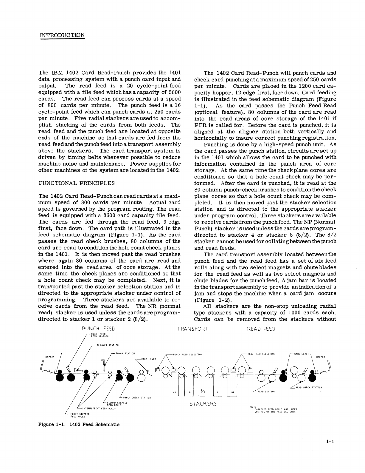
Figure
1-1.
1402
Feed
Schematic
NP
STACKERS
READ
NOTE
DARKENED
CONTROL
STATION
FEED
OF
THE
ROLLS
FEED
ARE
UNDER
CLUTCHES
1-1
NR
Page 7
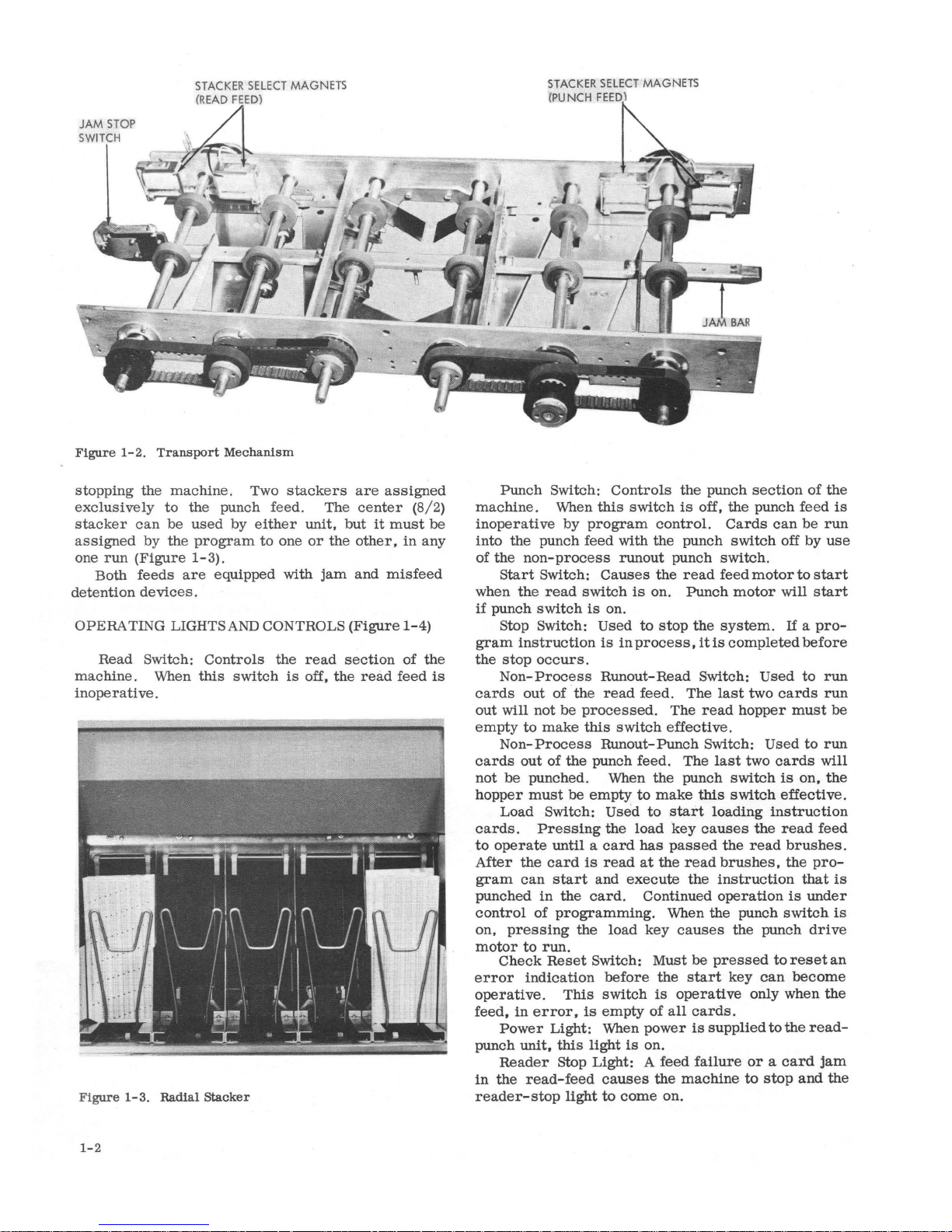
JAM
STOP
SWITCH
Figure
1-2.
Transport
Mechanism
STAC
KER SELECT MAGNETS
rpUNCH
stopping
exclusi
stacker
assigned
one
Both
detention
run
the
vely
can
by
(Figure
feeds
devices
machine
to
the
be
used
the
program
1-3).
are
.
OPERA TING LIGHTS
Read Switch:
machine
. When
Controls
this
inoperative.
Figure 1-3. Radial
Stacker
. Two
stackers
punch feed. The
by
either
to
equipped with
AND
switch
unit,
one
or
jam
CONTROLS
the
read
is
off,
are
center (8/
but
the
other,
and
(Figure
section
the
assigned
it
misfeed
read
must
in
1-4)
of
feed
2)
be
any
the
is
Punch
machine.
inoperative
into
of
the
Start
when
if
punch
Switch:
When
by
the
punch feed with
non-process
Switch:
the
read
switch
switch
Stop Switch:
gram
instruction
the
stop
occurs.
Non-
Process
cards
out
empty
cards
not
hopper
out
of
the
will not be
to
Non-
Process
out
make
of
the
processed.
this
be punched. When
must
be
Load Switch:
cards.
to
After
gram
punched
control
on,
motor
error
operate
the
can
of
pressing
to
Check
indication
PreSSing
until a card
card
is
start
in
the
programming.
the
run.
Reset
operative. This
feed,
in
error,
Power
punch
unit,
Reader
in
the
read-feed
reader-stop
is
Light: When
this
stop
light
Controls
this
switch
program
control.
the
runout
Causes
is
on.
Used
is
Runout-
read
the
is
on.
to
stop
in
process,
Read
feed. The
The
switch
Runout-
effective.
Punch
punch feed.
the
empty
card
to
Used
to
the
load
has
read
at
and
execute
. Continued
make
start
key
passed
the
When the punch
load
key
Switch:
before
switch
empty
Must
the
is
of
all
power
light
is
on.
Light: A feed
causes
to
come
the
on.
the
punch
is
off,
punch
punch
read
switch
feed
Punch
the
system.
it
is
Switch:
last
read
Switch:
The
last
punch
this
loading
causes
read
brushes,
the
instruction
operation
causes
be
pressed
start
operative
cards.
is
supplied
failure
machine
section
the
punch
Cards
switch
can
off
.
motor
motor
will
completed
Used
two
cards
hopper
Used
two
cards
switch
switch
is
effective.
instruction
the
read
the
read
the
punch
to
key
can
only when
to
or a card
to
stop
of
the
feed
be
run
by
use
to
start
start
If
a
pro-
before
to
run
run
must
to
run
will
on,
the
feed
brushes.
the
pro-
that
is
under
switch
drive
reset
become
the
the
read-
jam
and
the
is
be
is
is
an
1-2
Page 8
Figure
g
=
1-4.
Operating
PUNCH
STOP
Controls
CHIPS
STACKER
CHECK
RESET
BB
POWER
TRANSPORT
REAOER
CHECK
g
~
Punch
in
the
Punch Stop
Validity Light:
character
Reader
control
is
detected
Punch
control
is
detected
Stacker
full,
The
stops.
Transport
jam
the
transport
FUNCTIONAL SWITCHES
Cover
respective
the
punch
Punch
locking
to
the
Die
function
frame
Crank
switch
crank.
stop
punch feed
light
is
Check Light:
of
the
during
Check Light:
of
the
during
Light:
the
stacker
light
may
contact.
Interlocks:
interlock
and
Magazine
lever
punch
Lift
Interlock:
as
the
is
lowered.
Interlock:
which
It
provides
Light: A feed
causes
to
come
This
detected
data
data
Light:
It
feed
reader,
is
motor
magazine
must
during
processing
card
processing
the
If
any
light
goes
come
on
indicates
roll
switch
motor
Interlock:
opened,
and
This
be
the
reading.
punching of a
This
area.
When a
motor
This
turned
same
failure
the
machine
on.
light
comes
read
operation.
This
light
system
This
light
system
of
the
five
on and
shortly
that a card
this
interlock
the
before
light
is
cover
will open
and
run
When
switch
start
switch
is a manually
off
to
function
or a card
to
stop
on
if
comes
when
comes
when
card.
stackers
machine
the
turned
has
jammed
is
opened,
the
circuits.
the
opens
the
relays.
provides
when
the
insert
as
the
jam
and
the
an
invalid
on
under
anerror
on
under
an
error
become
stops.
machine
on
by the
in
the
circuit
magazine
the
lowering
operated
magazine
circuit
same
the
hand
to
interlock
function
removed
the 5 stackers
the
circuits.
indicating
provides
except
light
hinged
circuit
when
chine.
motor
indicating
SPECIFICA TIONS
Dimensions:
Weight:
BTU Rating:
while
using
Die
Interlock:
as
the
magazine
or
improperly
Stacker
circuit
Jam
Joggle Switch:
Chips 1 and 2 Switches:
Switch: This
to
It
also
light
Bar
Switch: When a
the
that
it
when
transferred.
front
joggler
to
the
the
chip box
Operation
and
run
lamp.
57
1/2"
29
3/4"
45
1/4"
1300
lbs
3,500 BTU
are
the
closes
when
same
completes a circuit
reader
of
circuits
wide
deep
high (plus
the
hand
This
switch
interlock
located.
switch
filled. When
punch and
the
transferred.
jam
function
This
assembly
motor
is
full
either
as
as
switch
control
These
or
removed
switch
well
as
read
file feed 14
crank.
provides
when
operates
transferred,
reader,
circuit
is
is
to
occurs,
the
stacker
to
operated
opened.
relay.
switches
will open
light
up
start
from
the
the
die
when any of
it
opens
and
the
stacker
this
switch
switch
the
transport
when
Itopens
operate
the
the
punch
the
"chips"
5/8")
same
is
run
the
the
ma-
1-3
Page 9

Page 10
READ
FEED
DRIVE MECHANISM
A 1/ 4
feed. The
When
to
CB (if
hp
1.
Timer
2.
Clutch
3.
Two
4.
First
5.
Continuously
6.
File
7.
Three
8.
Stacker
the
the
following:
1.
Picker
2.
Feed
3.
First
4.
Clutch
installed)
motor
drives
following
index
ratchet
contact
feed
roll
feed
drive
transport
jogglers
read
clutch
knife
knives
feed
roll
controlled
(Figure
are
kept
rolls
after
running
shaft
feed
for
engages,
cam
shaft
before
1-1)
the
input
continuously
each
CB / s (RC)
rolls
NR, 1
power
each
CB's
(RL)
pulley on
contact
and
8/ 2
is
contact
and
the
read
running:
roll
pockets.
transmitted
roll
solar
cell
Adjust
per
READ
the
minute.
CLUTCH
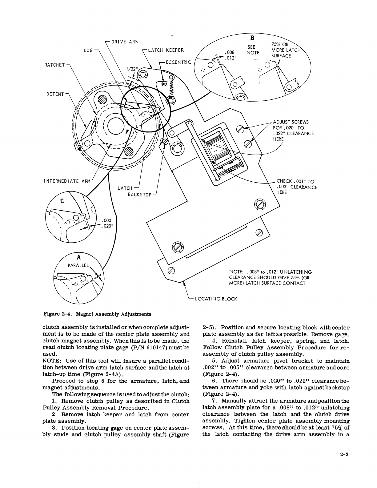
Principles
The
clutch
one-half
is
engaged
controlled
mediate
The
dog
the
ratchet.
drive
arm
of
the
intermediate
on a
sleeve
2-3).
motor
of
Operation
ratchet
revolution
by a drive
by
the
arm.
and
They
and
are
that
RLCB
UNIT
pulley
is
continuously
each
action
detent
pivot
controlled
arm.
is
the
hub
to
feed
cards
machine
dog
and
of
the
are
spring-loaded
on
studs
by
The
intermediate
of
the
running
cycle.
detent,
drive
that
studs
drive
800+ 3 - 20
and
This
ratchet
which
arm
and
to
are
part
that
are
arm
arm
(Figure
cards
makes
are
inter-
engage
of
the
part
pivots
GENEVA
CHIP
BOX--tlI---
PMT
(PUNCH
HD
(BEHI
---fi
MAGNET
RELAYS
ND
FUSE
AND
PANEL)
.....
TERMINALS)
MAIN
CONTACTOR
BRUSH
(REAR
IMPULSE
OF
RELAY
_ _ J
TRANSISTORS
GATE)
GT
(GATE
TERMINALS)
Figure
2-1.
1402
Front
View
2-1
Page 11
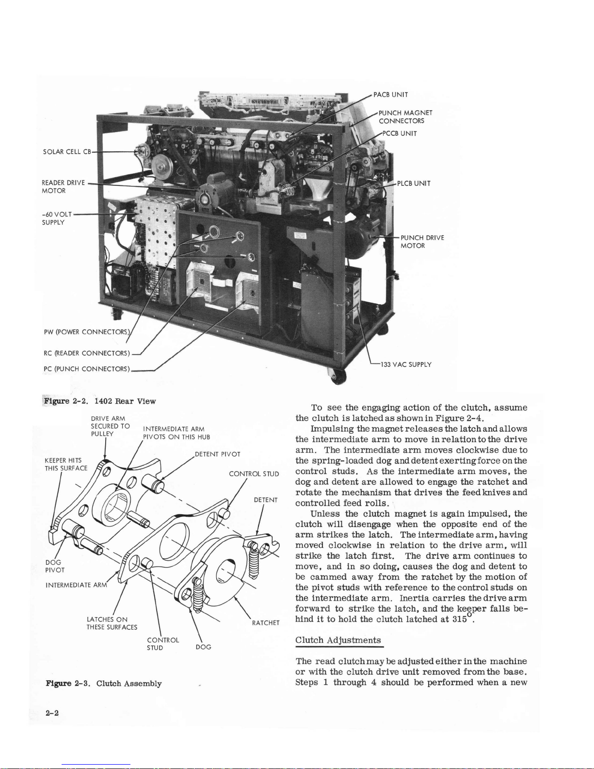
SOLAR CELL
READER
DRIVE
MOTOR
-60 VOLT
SUPPLY
PC
(PUNCH
CB
.....
I---~
~I-I!!~~~
CONNECTORS)
.I~
l~
PUNCH
MOTOR
DRI
VE
Figure
I N
TER
MEDIA
Figure
2-2.
2-3.
1402
DRI
S
ECURED
PULLEY
TE ARM
Clutch
Rear
VE ARM
View
TO
I NTERMEDIA
PIVOTS
Assembly
TE ARM
O N THIS HUB
DOG
To
see
the
engaging
the
clutch
Impulsing
the
intermediate
arm.
the
spring-loaded
control
dog and
rotate
controlled
Unless
clutch
arm
moved
strike
move,
be
cammed
the
pivot
the
intermediate
forward
hind
is
The
studs.
detent
the
mechanism
will
strikes
clockwise
the
and
studs
to
it
to
hold
latched
the
magnet
arm
intermediate
As
are
feed
rolls.
the
clutch
disengage
the
latch.
latch
first.
in
so
doing,
away
with
arm.
strike
the
Clutch Adjustments
The
read
clutch
may
or
with
the
clutch
Steps 1
through
4 should be
as
shown
to
dog
and
the
intermediate
allowed
that
magnet
when
The
in
relation
from
reference
Inertia
the
latch,
clutch
be
adjusted
drive
action
of
in
Figure
releases
move
in
arm
moves
detent
to
engage
drives
is
the
intermediate
to
The
drive
causes
the
ratchet
to
carries
and
latched
unit
removed
performed
the
clutch,
the
latch
relation
clockwise
exerting
arm
the
the
feed
again
opposite
the
drive
arm
the
dog and
by the
the
control
the
keeper
at
315
either
assume
2-4.
and
to
the
force
moves,
ratchet
knives
impulsed,
end
arm,
arm,
continues
detent
motion
studs
the
drive
falls
0
.
in
the
machine
from
the
when a
allows
drive
due
to
on
the
the
and
and
the
of
the
having
will
to
to
of
on
arm
be-
base.
new
2-2
Page 12
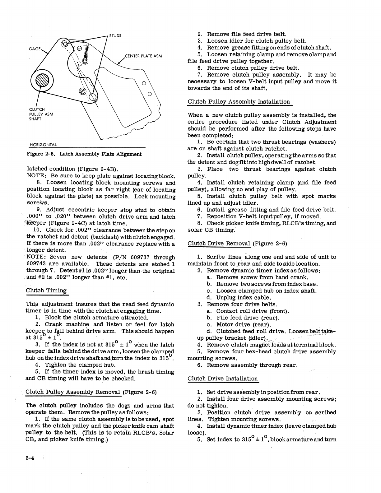
RATCHET
DRIVE
ARM
KEEPER
B
SEE
NOTE
LOCATING
ADJUST
FOR.020"
• 022" CLEARANCE
HERE
-_-l.--
NOTE:
.008"
CLEARANCE SHOULD GIVE 75%
MORE) LATCH
BLOCK
to
.012"
SURFACE
CHECK.
.003"
HERE
UNLATCHING
SCREWS
TO
001" TO
CLEARANCE
(OR
CONTACT
Figure
2-4.
clutch
ment
clutch
read
assembly
is
to
be
magnet
clutch
Magnet
locating
Assembly
is
installed
made
of
assembly.
plate
the
center
When
gage
Adjustments
or
used.
NOTE:
tion
latch-up
magnet
Pulley
plate
bly
Use
of
between
drive
time
Proceed
to
adjustments.
The
following.
1.
Remove
Assembly
2. Remove
assembly.
3.
Position
studs
and
this
tool will
arm
(Figure
step 5 for
sequence
clutch
Removal
latch
keeper
locating
clutch
pulley
insure a parallel
latch
surface
2-4A).
the
is
used
pulley
as
Procedure.
and
gage on
assembly
when
complete
plate
this
is
to
(PiN
610147)
and
armature,
to
adjust
described
latch
center
adjust-
assembly
be
made,
must
condi-
the
latch
latch,
the
clutch:
in
Clutch
from
center
plate
assem-
shaft
(Figure
and
the
be
at
-and
2-5).
Position
plate
assembly
4.
Reinstall
Follow
Clutch
assembly
5.
Adjust
.002"
to
(Figure
6.
There
tween
armature
(Figure
7. Manually
latch
assembly
clearance
assembly.
screws.
the
latch
of
clutch
armature
.005"
2-4).
should
2-4).
between
Tighten
At
this
contacting
and
secure
as
far
left
as
latch
keeper,
Pulley
Assembly
pulley
assembly.
pivot
clearance
be
between
.020"
and yoke with
attract
plate
the
for a .008"
the
latch
center
time,
there
the
drive
locating
possible.
spring,
Procedure
bracket
to
.022"
latch
armature
to
and
plate
assembly
should
arm
block
withcenter
Remove
to
armature
clearance
against
and
position
.012"
the
clutch
be
at
least
assembly
gage.
and
latch.
for
re-
maintain
and
core
be-
backstop
the
unlatching
drive
mounting
75%
of
in
2-3
a
Page 13
HORIZONTAL
Figure
2-5.
Latch
Assembly
Plate
Alignment
latched
condition (Figure 2-4B).
NOTE:
Be
sure
to
keep
plate
against
locating block.
8.
Loosen
locating block mounting
screws
and
position
locating
block
as
far
right
(ear
of
locating
block
against
the plate)
as
possible.
Lock mounting
screws.
9.
Adjust
eccentric
keeper
stop
stud
to obtain
.
000"
to
..
020"
between
clutch
drive
arm
and
latch
~er
(Figure
2-4C)
at
latch
time.
10. Check
for
.002"
clearance
between the
step
on
the
ratchet
and
detent
(backlash) with
clutch
engaged.
If
there
is
more
than
.002"
clearl;l,nce
replace
with a
.
longer
detent.
"
N9TE:
Seven new
detents'
(PIN
609737 through
609743
are
available.
These
detents
are
e~ched
1
through
7.
Detent#l
is
.002"
longer
than·the
original
'alld #2
is
.002"
longer
than
#1.
etc.
Clutch
Timin~
Thi/:l
adjustment
insures
that
the
read
feed dynamic
timer
is
in
time
with the
clutch
at
engaging
time.
1. Block the
clutch
armature
attracted.
2.
Crapk
machine and
listen
or
feel
for
latch
keeper
to
fall
behind &-ive
arm.
This
should happen
at
315
0
± 10. .
. 0 0
3.
If
the
index
is
not
at
315 ± 1 when the
latch
keeper
falls
behind the
drive
arm,loosen
the
clamped
. 0
hub on the index
drive
shaft
and.,turn the index
to
315 .
4. Tighten the
clamped
hub.
5.
If
the
timer
index
is
moved, the
brush
timing
and CB
timing
will have
to
be
checked.
Clutch
Pulley
Assembly
Removal (Figure 2-6)
The
clutch
pulley includes
the
dogs
wd
arms
that
operate
them.
Remove the pulley
as
follows:
1.
If
the
same
clutch
assembly
is
to
be
used,
spot
mark
the
clutch
pulley and 'the
picker
knife
cam
shaft
pulley
to
the
belt.
(This
is
to
retain
RLCB's,
Solar
CB, and
picker
knife timing.)
2-4
2. Remove file feed
drive
belt.
3.
Loosen
idler
for
clutch
pulley
belt.
4. Remove
grease
fitting on
ends
of
clutch
shaft.
5.
Loosen
retaining
clamp
and
remove
clamp
and
file feed
drive
pulley
together.
6.
Remove
clutch
pulley
drive
belt.
7. Remove
clutch
pulley
assembly.
It
may
be
necessary
to
loosen
V-belt
input pulley
and
move
it
towards
the end of
its
shaft.
Clutch
Pulley
Assembly
Installation
When a new
clutch
pulley
assembly
is
installed,
the
entire
procedure
listed
under
Clutch Adjustment
should be
performed
after
the following
steps
have
been
completed:
1. Be
certain
that
two
thrust
bearings
(washers)
are
on
shaft
against
clutch
ratchet.
2.
Install
clutch pulley,
operating
the
arms
so
that
the
detent
and
dogfitintohighdwellof
ratchet.
3.
Place
two
thrust
bearings
against
clutch
pulley.
4.
Install
clutch
retaining
clamp
(and file feed
pulley), allowing no end play
of
pulley.
5.
Install
clutch pulley
belt
with
spot
marks
lined up and
adjust
idler.
6.
Install
grease
fitting and file feed
drive
belt.
7. Reposition
V-belt
input pulley,
if
moved .
8. Check
picker
knife
timing.
RLCB's
timing.
and
solar
CB
timing.
Clutch
Drive
Removal (Figure 2-6)
1.
Scribe
lines
along one end and
side
of
unit
to
maintain'front
io.,l!ear,and
side
to
side
location.
2. Remove dynamic
timer
index
as
follows:
a.
Remove
screw
from
hand
crank.
b. Remove two
screws
from
index
base.
c.
Loosen
clamped
hub on index
shaft.
d. Unplug index
cable.
3. RemoVe
four
drive
belts.
a.
Contact
roll
drive
(front).
b.
File
feed
drive
(rear).
c.
Motor
drive
(rear).
d. Clutched feed
roll
drive.
Loosen
belt
take-
up pulley
bracket
(idler)~:,
;."
... , .... , ~ .
4. Remove
clutch
magti.etIeads
at
terminal
block.
5. Remove four
hex-head
clutch
drive
assembly
mounting
screws.
6. Remove
assembly
through
rear.
Clutch
Drive
Installation
1. Set
drive
assembly
in
position
from
rear.
2.
Install
four
drive
assembly
mounting
screws;
do not tighten.
3.
Position
clutch
drive
assembly
-on
scribed
lines.
Tighten mounting
screws.
4.
Install
dynamic
timer
index (leave
clamped
hub
loose).
0 0 . '
5. Set index to 315 ± 1 • block
armature
and
turn
Page 14

REVERSE
LOCK
CLUTCH
PULLEY
ASSEMBL
·Y
'----DRiVE
PULLEY
Figure
2-6.
Clutch
Drive
Assembly
machine
until
detent
keeper
falls
behind
drive
arm
.
Tighten
clamping
hub.
6.
Install
clutch
drive
belt
and
adjust
idler
pulley
.
At
this
time
loosen
the
picker
knife
camshaft
pulley
locking
screws
.
7.
Timing
the
picker
knife
camshaft
can
be
accomplished
by
tripping
the
read
clutch
and
setting
the
timer
at
2160 for
a 2
group
brush
machine
or
o
212
for
a 3
group
brush
machine. Place a card
in
the
hopper
up
against
the
first
feed
rolls. Turn
the
cam
shaft
in
the
normal
machine
direction
until
the
feed
knives
touch
the
card.
Tighten
the
pulley
lock
screws. This
is a starting
point
for
brush
timing.
Refer
to
wiring
diagram
for
the
final
brush
timing.
Change
the
picker
knife
camshaft
for
the
proper
brush
timing
by
slipping
the
drive
pulley
on
the
cam
shaft.
8.
Time
RC
CB's,
using
the
set
screw
retained
gear
on
the
RC CB
shaft.
9.
Install
the
other
three
belts
and
unblock
the
clutch
armature.
10.
Check
the
following
timings
:
o 0
a.
Clutch
engagement
time
(315 ± 1 ).
b.
Brush
impulse
CB
timing.
c.
RC CB
timing.
d.
RL
CB
timing.
TIMER
INDEX
SHAFT
·
MAGNET
ASSEMBLY
FILE
FEED
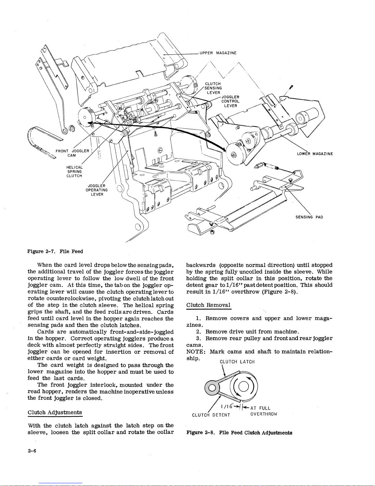
Principle
of
Operation
(Figure
2-7)
The
file
feed
consists
of
two
basic
units:
1.
Upper
magazine.
2.
Lower
magazine.
The
upper
magazine
is
the
tray
which
holds
up
to
3600
cards
to
be
fed
into
the
hopper.
This
tray
is
hinged
and
can
be
locked
at
an
angle
to
make
the
brush
area
of
the
machine
more
accessible.
The
lower
magazine
contains
clutch
contr01led
feed
rolls
that
feed
the
cards
into
the
hopper.
Opera-
tion
of
the
helical
spring-type
feed
roll
clutch
is
controlled
by
the
level
of
the
cards
in
the
hopper.
Under
spring
tension,
tlJ-e
front
joggler
applies
pres·':'
sure
on
the
joggler
operating
lever,
causing
the
lever
to
follow
the
contour
of
the
front
joggler
cam. As
the
front
joggler
cam
rotates,
the
front
j<;>ggler
oscillates,
joggling
the
cards
into
position.
If
there
are
sufficient
cards
in
the
hopper
to
cover
the
sensing
pads,
the
inward
travel
of
the
joggler
is
limited
and
the
joggler
control
lever
is
not
allowed
to
follow
the
low
dwell
of
the
front
joggler
cam. There
will
be
no
clutch
action
or
cards
fed down
into
the
hopper
at
this
time.
2-5
Page 15
HELICAL
SPRING
CLUTCH
JOGGLER
OPERATING
LEVER
o
I
/\
'~'
.
"v.
CLUTCH
SENSING
LEVER
/~
JOGGLER
CONTROL
LEVER
\
~
LOWER
MAGAZINE
Figure
2-7.
When
the
additional
operating
joggler
erating
rotate
of
grips
feed
counterclockwise,
the
step
the
until
sensing
Cards
in
the
hopper.
deck
with
joggler·
either
cards
The
lower
feed
magazine
the
The
read
hopper,
the
front
Clutch
With
Adjustments
the
sleeve,
File
the
lever
cam.
lever
in
shaft,
card
pads
are
almost
can
card
last
front
joggler
clutch
loosen
Feed
card
level
travel
At
will
and
to
this
the
and
level
then
of
follow
time,
cause
clutch
the
in
the
automatically
Correct
perfectly
be opened
or
card
weight.
weight
into
is
the
cards.
joggler
renders
is
closed.
interlock,
the
latch
the
split
drops
below
the
joggler
the
low dwell
the tab
the
clutch
pivoting
sleeve.
feed
rolls
the
hopper
clutchlatches.
front-and-side-joggled
operating
straight
for
insertion
designed
hopper
machine
against
the
collar
the
sensing
forces
on
the
operating
the
clutch
The
helical
are
driven.
again
jogglers
sides.
or
to
pass
and
must
mounted
inoperative
latch
and
rotate
the
joggIer
of
the
joggler
lever
latch
spring
Cards
reaches
produce
The
removal
through
be
used
under
unless
step
on
the
collar
pads,
front
op-
to
out
the
front
of
the
to
the
the
a
backwards
by
the
spring
holding
detent
result
Clutch
the
gear
in
Removal
1. Remove
zines.
2. Remove
3. Remove.
cams.
NOTE:
Mark
ship.
CLUTCH 0 ETEN
Figure
2-8.
(opposite
fully
split
to
1/16"
1/16"
CLUTCH
File
normal
uncoiled
collar
past
overthrow
covers
drive
unit
rear
pulley
cams
and
LATCH
T
Feed
Clutch
direction)
inside
in
this
detent
(Figure
and
upper
from
and
shaft
Adjustments
the
sleeve.
pOSition,
position.
2-8).
and
machine.
front
and
to
maintain
until
rotate
This
lower
rear
relation-
stopped
While
the
should
maga-
joggler
2-6
Page 16
4. Remove
5. Loosen
grease
shaft.
shaft
of
fitting), and
These
and
rear
of unit.
6.
Remove
unit. The
spring
removed.
7.
Re-assemble
have the
positions,
shaft. The
cam
should hold the
in
full
mesh.
should hold the
mesh.
The
not squeeze
when the
justments
set
must
clutch
clutch
and
the
clutch
sleeve
the
clutch
after
rear
bearing
side
joggler
clutch
screws
be
loosened a full
clutch
can
in
latch
grease
drive
clutch
The
sleeve
clutch
and the
clutch
is
latched. Check
the
unit
Service Checks
front
1/16"
upper
side
front
joggler
travel
card
frames.
joggler
1. The
approximately
2.
The
between the
3.
The
free
of binds between
magazine.
4. Hopper bed
plate
above hopper bed plate.
5.
zine
Shims
if
the
are
speed
available
nuts
interfere
clutch.
6. The
.040"
tops of the feed
above
lower
the
magazine
imaginary
rolls
(Figure 2-9)
retainer
cam,
drive
are
seated
assembly
now be
dis-assembled
reverse
and the
detent
fittings
sleeve
together,
and the
together,
side
so
tightly
is
replaced
interlocking
before
deck
support
operating
the
side
springs
to
shim
throat
plane
plate.
clutch
gear
turn.
on
joggler
in
undercuts
Slide
hub (with
shaft
through bottom of
order.
and
in
over
the
Be
their
the
side
careful
correct
slotin
with the
side
joggler
with the
joggler
as
plates
must
with the
clutch
cam
to
cause
all
drive
in
the
machines.
arm
should have
contact
must
makes.
be
levers
and
be
3/8" ± 1/16"
the
lower
helical
should be
unit
centered
must
the
.020"
determined
.
cam
on
out
and the
to
the
joggler
clutch
cam
in
full
should
binding
ad-
be
lower
magaspring
to
by the
.020
TO
.040
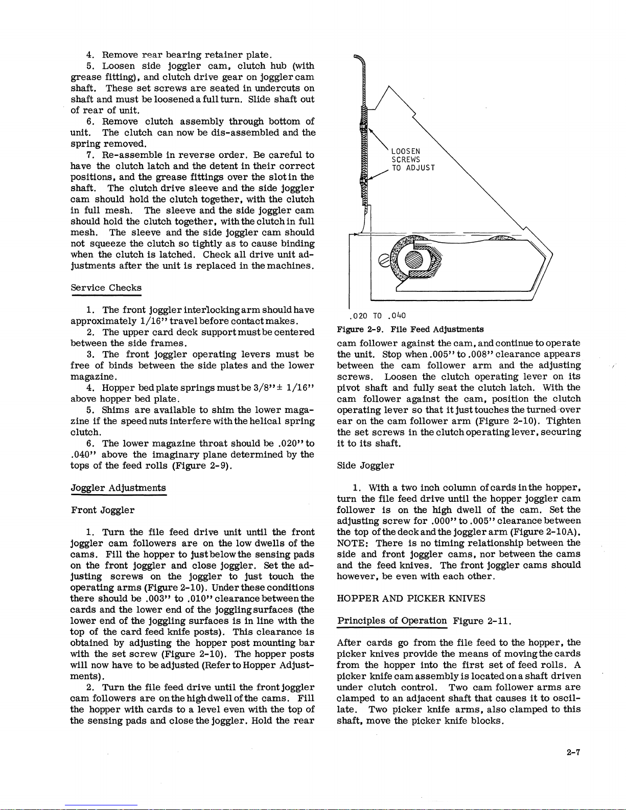
Figure
cam
2-9.
File
follower
Feed
against
the unit. Stop when
between the
screws.
pivot
shaft
cam
follower
operating
ear
on the
the
set
it
to
its
Side
Joggler
cam
Loosen the
and fully
lever
cam
screws
shaft.
against
so
follower
in
the
Adjustments
the
cam,
.005"
to
follower
clutch
seat
the
the
that
it
just
arm
clutch
and continue
.008"
clearance
arm
and the
operating
clutch
cam,
position the
touches the
to
operate
appears
adjusting
lever
on
latch. With the
clutch
turned
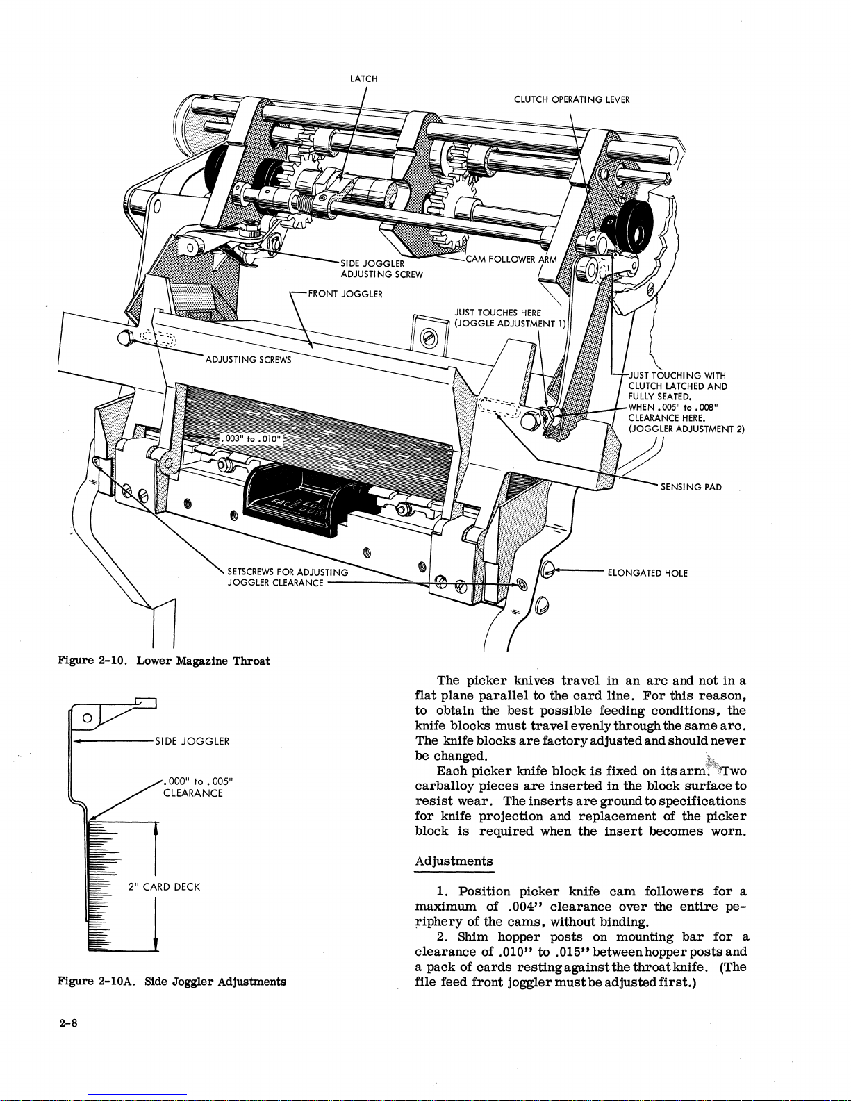
(Figure 2-10). Tighten
operating
lever, securing
its
'over
Joggler
Front
joggler
camS.
on the
justing
operating
there
cards
lower
top
Adjustments
Joggler
1.
Turn
cam
Fill
front
screws
should
and the
end of
of
the
the
arms
card
obtained by
with the
set
will now have
ments).
2.
Turn
cam
followers
the
hopper with
the
sensing
pads and
the file feed
followers
hopper
joggler
on
to
and
the
(Figure 2-10).
be
.003"
to
lower
end of the joggling
the
joggling
feed knife
adjusting
screw
to
(Figure
be
adjusted
the
the file feed
are
on
the
cards
to a level
close
drive
unit
until
are
on
the
low
just
below
the
close
joggler.
joggler
to
just
Undertheseconditions
.010"
clearance
surfaces
posts).
hopper
is
This
post
in
2-10). The
(Refer
to
Hopper
drive
until
the
high dwell of the
even
the
joggler.
the
dwells
of the
sensing
Set
the
touch
between
surfaces
line with
clearance
mounting
hopper
Adjust-
frontjoggler
cams.
with
the
top of
Hold the
front
pads
ad-
the
the
(the
the
is
bar
posts
Fill
rear
1. With a two inch column of
turn
the
follower
adjusting
the
top of the
NOTE:
side
and
file feed
is
screw
There
front
drive
until
on the high dwell of the
for
.000"
deck
and the
is
no
timing
joggler
cams,
and the feed knives. The
be
even
with
however,
HOPPER
Principles
After
picker
from
picker
under
clamped
late.
shaft,
AND
of
cards
knives provide
the hopper into the
knife
cam
clutch
to
an
Two
picker
move the
PICKER KNIVES
Operation
go
control.
adjacent
each
from
the
the
assembly
knife
picker
knife
Two
shaft
the
to
.005"
joggler
arm
relationship
nor
front
joggler
other.
Figure
2-11.
file feed
means
first
set
is
located
cam
that
arms,
also
blocks.
cards
in
the
hopper
joggler
cam.
clearance
(Figure 2-10A).
between the
between the
cams
to
the
hopper,
of moving
of feed
on a
shaft
follower
causes
it
clamped
hopper,
cam
Set
between
cams
should
the
cards
rolls.
driven
arms
to
oscil-
to
the
the
A
are
this
2-7
Page 17
LATCH
CLUTCH
OPERATING
LEVER
Figure
II------SIDE
Figure
2-10.
Lower
2"
CARD
2-10A. Side
Magazine
JOGGLER
• 000"
to
CLEARANCE
• 005"
DECK
Joggler
Throat
Adjustments
The
picker
flat
plane
parallel
to obtain the
knife blocks
best
must
The knife blocks
be changed.
Each
picker
carballoy
resist
for
block
wear.
knife
is
pieces
The
projection
required
Adjustments
1.
Position
of the
of .010"
cards
front
.004"
cams,
joggler
maximum of
riphery
Shim hopper posts on mounting
2.
clearance
a pack of
file feed
III~I+---
knives
travel
to the
card
ELONGATED
in
an
arc
line.
For
HOLE
and not
this
possible feeding conditions, the
travel
evenly through the
are
factory adjusted and should
knife block
are
inserts
when the
picker
is
inserted
are
ground to specifications
and
replacement
knife
clearance
fixed on
in
the block
insert
cam
over
same
its
arm~~ITwo
surface
of the
becomes worn.
followers
the
entire
without binding.
bar
to
.015"
between hopper
posts
restingagainstthethroatknife.
must
be adjusted
first.)
in
reason,
arc.
never
~.
to
picker
for
pe-
for
and
(The
a
a
a
2-8
Page 18
PICKER
KNIFE
BLOCK
Place a card
manually
rection
Tighten pulley locking
NOTE: Any change
directly
machine).
and
timings.
until
adjustments
against
turn
the
picker
the feed knives touch the
affect
RC
Be.
sure
.carefully
the
camshaft
screws.
in
picker
CB and
to
check
first
knife
solar
before
feed
machine
timing
CB (if on
brush
making
rolls
card.
timings
these
and
di-
will
HOPPER
Figure 2-11.
rear
the
of
the
NOTE:
centered
(5/16" ± 1/32"
.020"
fingerS,
so
that
.020"
when
the
lined up with the
.0105"
card
BED
Picker
3.
With a
hopper
front
card.
4.
Adjust
to
5.
~osition
the
to
the
6. The
step
7.
The
so
clearance
side
side
plate
This
adjustment
between the
the
.050"
(Figure
feed edge of the
.030"
card
throat
indicating the
throat
no-go.
that
the
Knife
of
.062" ± .005"
plate
and the
for
.016"
to
should
rails
from
the
front
hopper
clearance
2-12).
the feed knife
beyond
is
throat
Time
trailing
back
to
arms
picker
the
trailing
held
against
roller
opening should be
must
center
knife face.
the
picker
edge of a
rear
.021"
in
the
rail).
plate
the
be
line
knife
between the
side
frame.
over
result
transport
card
guide
hopper
evenly
knife
block
edge of a
the
hopper
positioned
of
the
.0095"
cams
card
adjust
the length
in
cards
area
fingers
bed
plate
on
the
shaft
travels
card.
posts.
so
that
roller
go and
to
feed a
aligns
witg
is
CARD
Adjustments
to
lower
line. Adjust
side
.020"
assembly.
CARD
Adjustments
GUIDES
Position
1.
.015"
below the
card
frames.
2.
Position.the
to
.050"
LEVERS
1. Make
the
first
lower
careltline.
guide
for
.015"
tcr
by
loosenihg the mounting
removable
clearance
sure
all
to
card
the
levers
card
Position
.025"
upper
first
lower
are
guide
for
the
below the
screws
card
guide
card
free
of
.005"
second
card
in
the
for
guide
binds.
::
~a:o:;
NOTE:
brush
timings.
line
(refer
the
pioker
To
adjust
a.
shaft
for~'
::s:~o:~
This
is
just a referenoe
When the
to
Brush
knife
oamshaft
proceed
Loosen
pulley
• 0
;:!~
~~~:e=Yo~:6~X:;U::r~:;~~~~!.
~~~
brushes
Assembly
to
as
follows:
clamped hub
~!ra~p;:a=h:!.
point
for
making
are
on
the
soribed
Adjustment).
obtain
on
proper
pioker
retime
timing.
knife
..
oarA"
.\';.
""",''-
'Figure
2-12.
Hopper
Back
Plate
Clearance
2-9
Page 19
2.
Position
all
card
lever
contacts
to
give a
mini-
mum
contact
travel
of
1/16"
when
the
card
lever
is
being
operated
by a card.
3.
Position
card
levers
and
contacts
to
provide
a
minimum
of
1/64"
rise
of
the
N/O
contact
strap
off
it
support.
4.
Adjust
the
contacts
for
1/32"
minimum
air
gap.
5.
Time
according
to
timing
charts
(dynami-
cally).
BRUSH
ASSEMBLY
Adjustments
(Figure
2-13)
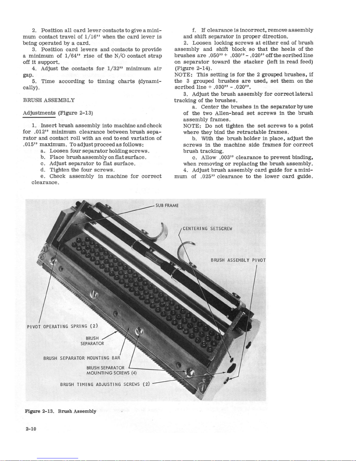
1.
Insert
brush
assembly
into
machine
and
check
for
.012"
minimum
clearance
between
brush
sepa-
rator
and
contact
roll
with
an
end
to
end
variation
of
.
015"
maximum.
To
adjust
proceed
as
follows:
a.
Loosen
four
separator
holding
screws.
b.
Place
brush
assembly
on
flat
surface.
c.
Adjust
separator
to
flat
surface.
d.
Tighten
the
four
screws
.
e.
Check
assembly
in
machine
for
correct
clearance.
SPRI
NG
(2)
BRUSH
SEPARATOR
MOUNTING
BRUSH
TIMING
ADJUSTING
SCREWS
Figure
2-13.
Brush
Assembly
2-10
f.
If
clearance
is
incorrect,
remove
assembly
and
shift
separator
in
proper
direction.
2.
Loosen
locking
screws
at
either
end
of
brush
assembly
and
shift
block, so
that
the
heels
of
the
brushes
are
.050" + .030" -.020"
off
the
scribed
line
on
separator
toward
the
stacker
(left
in
read
feed)
(Figure
2-14).
NOTE:
This
setting
is
for
the 2 grouped
brushes,
if
the 3 grouped
brushes
are
used,
set
them
on
the
scribed
line + .030" -.020"
.
3.
Adjust
the
brush
assembly
for
correct
lateral
tracking
of
the
brushes.
a.
Center
the
brushes
in
the
separatorbyuse
of
the
two
Allen-head
set
screws
in
the
brush
assembly
frames.
NOTE: Do
not
tighten
the
set
screws
to a point
where
they
bind the
retractable
frames.
b. With
the
brush
holder
in
place,
adjust
the
screws
in
the
machine
side
frames
for
correct
brush
tracking.
c.
Allow
.003"
clearance
to
prevent
binding,
when
removing
or
replacing
the
brush
assembly.
4.
Adjust
brush
assembly
card
guide
for a mini-
mum
of
.025"
clearance
to
the
lower
card
guide.
CENTERING
SETSCREW
Page 20
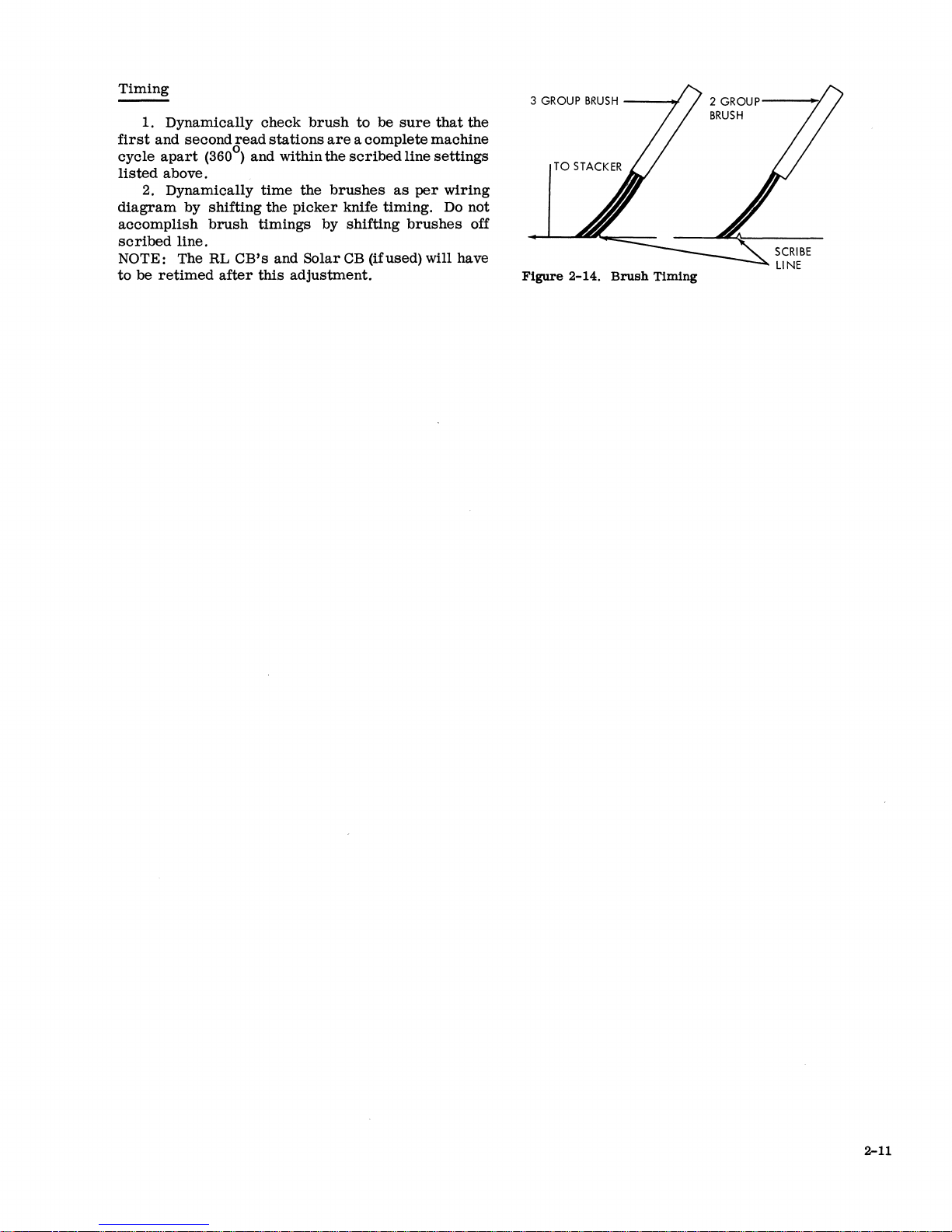
Timing
1.
Dynamically
first
and
second
cycle
apart
(360°)
listed
above.
2.
Dynamically
diagram
accomplish
scribed
by
line.
shifting
brush
NOTE: The RL
to
be
retimed
after
read
and
timings
CB's
this
check
stations
within
time
the
the
picker
and
adjustment.
brush
to
are a complete
the
scribed
brushes
knife
by
shifting
Solar
CB
(ifused) will have
be
sure
line
as
timing.
brushes
that
machine
settings
per
wiring
Do not
the
off
3
GROUP
Figure
BRUSH
2-14.
Brush
Timing
2
GROUP----/
BRUSH
2-11
Page 21

Page 22

TRANSPORT
SELECTION MECHANISM
Principles
The
transport
running
the
stacker
feed
rolls
three
are
go
into
feed. The
termined
the
transport
The
blades
and punch
energized.
stacker
feed;
punch.
two
chute
4.
If
the
energized.
stacker
A
jam
port
mechanism.
AND
of
Operation
feed
rolls
selected
are
under
only
three
stacker
by
the
mechanism
selection
and two
feeds.
the
NR
If
the
magnet
blades
magnet
the
8/2.
bar
is
STACKERS
mechanism
that
move
by
under
control
control
of
the
into which the
selection
mechanism
control
cards
cards
installed
With
enter
for
the
that
is
energized.
that
depresses
from
The
bar
magnets
chute
of
consists
cards
blades.
of the
the
punch feed.
five
stackers
mechanism
(Figure
consists
for
the
select
the
stacker
read
and
depresses
the
both chute
either
over
the length
consists
of
six
continuously
from
Three
read
card
enters
at
3-1).
each
magnets
stacker
the
cards
feed
of
of a
the
feeds
of the
feed.
Cards
from
each
of two
of
the
nearest
NP
for
lower
go into 1
blades
can
go
the
trans-
spring
to
and
can
either
is
deend
of
chute
read
de-
the
the
of
the
or
is
into
steel
strip
located
card
that
is
bent
a
switch
to
feed
circuits.
Chute
Magnet
loosening
tracted,
clearance
the
1/32" + 1/64"
are
card
ing
of
(Figure
to
stop
and
portion
Blade
Adjustment
1.
Lower
2.
With
3.
Adjust
mounting
not
energized,
line when
4.
Adjust
screw)
lower
3-3).
5. Chute
operate.
turns
and
four
pocket
adjust
between
for
chute
just
above
enough to flex the
The
on
the
stop
of
the
machine
Selector
(Figure 3-2)
control
holding
selector
screws)
chute
blade
key and
screws
selector
each
armature
upper
- 0 above
and
the
magnets
blades
1/32"±
blade and
tension
magnet
to
1/32" + 1/64"
1/64"
the
normal
switch
light. A
indicator
and pivoting.
magnet
part
of
position
card
line when
are
(use the
clearance
lower
should
card
metal
causes
card
is
detected
armatures
for
.035" ± .003"
stop
and
assembly
the
energized.
chute
card
be
such
line.
strip
causes
the
machine
jam
in
by
other
light
panel
armature.
(by
use
chute
blades
the
magnets
- 0 below
blade
mount-
between
guide
that a force
Any
the
by
at-
of
the
end
plate
PUNCH
Figure
PUNCH
COIL
FEED
3-1.
FEED
SELECT
MAGNETS
II
CARD
LlNE~
POCKET
N/P
Card
Selection
COIL
Schematic
t:::(
=====~
v
POCKET
4
POCKET
8/2
POCKET
I
READ
FEED
SELECT
L-
___
C_O_,L
____
~I
POCKET
N/R
MAGNETS
I~
__
C_O_,_L
____
~
READ
FEED
CARD
LI
NE
3-1
Page 23

CHECK
CHUTE
TENSION
GAGE
AT
Figure
WI
THI
TH
3-2.
:l
GRAM
S POINT
CHUTE
MOUNT!
Chute
ARMATURE
BLADE
NG
SCREW
Blade
STOP
and
Select
Magnet
Adjustments
SHEAR
Figure
3-4.
Jam
Bar
JAM BAR ADJUSTMENTS
ADJUSTI
PL4TE
NG
SCREW
of 280
magnet
backstop) should hold the
A
hold
force
select
to
400
armature
of 110
magnet 1
grams
(at a point
to
230
applied
to
the 2
just
armature
grams
or
should be
magnet 4 armatures
attracted.
6. With a chute blade
surface,
screw
flat
the
hole should
surface.
tab
containing
removed
project
the
chute blade mounting
1/8"±
TRANSPORT ROLL ADJUSTMENTS
1. The lower
directly
lished
the
mounting
to
the
of
from
Tension
1/4
same
below the
by
inserting a .010"
upper
and
brackets
the
card
line.
'2.
Tension on the
lower
feed
1.5
1b
to
between the
on
1b
of
each
direction
locknuts on the mounting
NOTE:
I + 0
32
Figure
-
1/64
CHUTE
3-3.
Push-pull
IN.---~I
BLADES
lower
roll
2.5
the
other.
Chute
pressure
upper
until the
shaft
1b
rolls
front
as
it
scale,
Blade
rolls.
rolls
and
pressure
mounting
is
required
and
rear
The
is
fed.
screws
PiN
_
...L
32
(Top View)
rolls
feeler
adjusting
feeler
(upper
rolls
card
must
After
9900012,
+ 0 IN
-1/64
SHEAR
should be
This
gage
rolls
screws
to
roll
adjusting, be
are
+
1/64
_ 0
or 8 selector
under
fully
armature
attracted.
required
fully
and held on a
1/64"
above
centered
can
be
accomp-
gage
leaf
between
the
lower
leaf
is
parallel
is
adjusted
so
that
pull a
card
strip
not turning).
should be within
be
pulled
in
sure
tight.
may
be
used.
.
PLATE
IN.
to
flat
the
roll
by
pull
the
1. A
jam
.035"
shear
port
lever
will be
clearance
plates
and
(Figure
2. The
operated
at
tape
STACKERS
Principles
The
The
mechanism
from
pivot and
the
card.
by
the
falls,
the
guide
approaches
restraining
The
alignment
support
supports
of Operation
stackers
stacker
with the
the top of
lever
As a
card
restraining
guided by
assembly
the bottom.
lever
card
lever
or
card
the
accumulate.
tension
lowers
The
supporting
the group of
pusher
bottom of the
until
the
card
ate
the
stacker
which
anism
read
the
operated
is
means
can
keep
they
stops
is
driven
feeds.
The
N/R
read
feed and the
by the punch feed. The
connected
of two
be
operated
The
card
the
cards
might
jam
bar
must
be
between the
over
the
entire
the junction of
3-4).
must
be
adjusted
with a
tape
(Figure
used
on the 1402
receives
the
card
the
guide
assembly
result.
the
lever.
the
guide
is
such
the
that
has
stops
with the
and the
front
previously
card
alignment
Their
weight
the
card
cards
slide
oscillating
card
deck
support.
deck
support
stop
microswitch
the
machine.
from
either
and 1
stacker
N/P
to
both the
helical
levers
from
the
springs
by
either
on the pivot and
going
machine.
positioned
formed
length of the
the
jam
for
points and the
card
bar
and
so
that
deflectionofl/16".
3-5)
are
the
radial
card
from
the
horizontal.
assembly
is
less
front
and the
assembly.
that
as
the
front
been
supporting
back
The
to
the
than
the length of
of the
card
rear
The
rear
falls
from
edge on the
edge on the
stacked.
lever
Spring
until 4
overcomes
alignment
into
the
card
pusher
front
to
back
This
can
moves
out enough
operating
The
card
jogg1er
or
both the punch and
jogg1ers
and 4
read
are
stacker
8/2
stacker
and punch
and
collars
operated
jogg1ers
feed.
lever
back
into the
stacker
.020"
trans-
jam
bar
the
switch
type.
transport
distance
lip
of
the
is
held
of
the
card
radius
of the
card
the
card
it.
card
card
deck
tension
to 6 cards
the
spring
lever,
and
slide.
works
continue
to
oper-
arm,
mech-
are
jogg1er
feeds
so
that
assembly
where
to
of
the
by
by
it
3-2
Page 24

CARD
DECK
SUPPORT
CARD
RESTRAI
ASSEMBLY
NI
NG
CARD
4 - 6
GUIDE
ASSEMBLY
ALIGNMENT
CARDS
LEVER
STACKER
SWITCH
Figure
four
the
HUB
HELICAL
Stacker
1. The
bearing
2.
two
3.
the
reader
spring
red
dot)
sleeve
IDENTIFIED
3-5.
Maintain
With
is
STOP
stacker
Joggler
three
bracket
inside
the
feed
sleeve.
for
.003"
flush
MATI
Schematic
Adjustments
shaft
must
assemblies).
4.000" ± .005"
bearing
center
adjust
against
WITH
NG
and
to
HUB
brackets
shaft
the
the
.005"
the
RED
be
free
between
(Figure
assembly
clutch
hubs
clutch
clearance
mating
CARD
PUSHER
SLIDE
of
binds
(align
the
the
bases
of
3-7).
shifted
flush
hub (identified by a
while
hub.
with
its
toward
the
spring
Stacker
1. Make
freely
should
transport
with no binds.
2.
The
be 3 5/16" ± 1/64".
3.
The
4.
Form
HELICAL
ECCENTRIC
JOGGLE
TO
Adjustments
space
pocket
rails
SPRING
FRONT
sure
the
CARD
all
separators
within
radial
TO
OF
MACHI
sliding
between
.015".
guide
SLEEVE
NE
and pivoting
the
pocket
should
as
shown
be
in
parts
move
separators
square
Figure
with
3-6.
1~.~
___
F_L_U_S_H~
Figure
3-7.
Center
stacker
Joggler
READ
FEED
END
___
~
____
.O::~::H_~_::_:_5
Assembly
________
.~~1
MOUNTING
BRACKETS
3-3
Page 25

ADJUSTMENT
MALFORMED
CAN
BE A CAUSE
CARD
THIS
AS A CAUSE,
GUIDES
TED
PROFILE.
THIS
PROFI
REINSTALLATION.
SCREW
ELONGATE
SCREW
EXTENT
OF
STACKER
RADIAL
JAMMING.
TO
MATCH
DO NOT
LE
TO
HOLES
DO NOT
THE
HOLE
TO
BY
FI
LI
RADIAL
CARD
OF
EXCESSIVE
TO
ELIMINATE
FORM
THE
ILLUSTRADISTORT
ACCOMPLISH
IF
MOUNTING
ALIGN,
UPPER
MOUNTING
THE
REQUIRED
NG.
CARD
GUIDES
THESE
GUIDES
3...,4,
Figure
3-6.
Radial Card Guide OUtline
Page 26

PUNCH
FEED
DRIVE MECHANISM
1/3 hp
A
Through
kept
10.
When
to
the
feature)
feed
to
turn,
PUNCH
Principles
motor
is
used
gears
continuously running:
1.
Timer
2. Clutch
3. Geneva
4.
Intermittent
5.
Punch
6.
PACB's
7.
PCCB's
B.
First
9.
Three
Stacker
the
following:
1.
Picker
2.
Feed
3.
First
4.
First
5.
Card
6. Second stepped
7.
Punch
B.
PLCB's
9.
Punch
When
rolls
they
FEED
and
index
ratchet
assembly
unit
drive
feed
roll
transport
jogglers
punch
clutch
knife
knives
feed
rolls
stepped
aligners
check
feed
the
punch clutch
are
cammed
cannot feed a
CLUTCH
of
Operation
(Figure
to
drive
timing
feed
cam
roll
brush
read
belts,
rolls
shaft
after
the punch
feed
rolls
engages,
shaft
assembly
roll
assembly
contact
brush
latches,
open and though
card.
1-1)
the
input
the following
power
roll
contact
the
idler
pulley.
check
brushes
is
transmitted
roll
(optional
intermittent
they
continue
are
Clutch Adjustments
clutch
The
should not have
performed
1. Set
zontal
(Figure
so
that
carrier
follower
2.
the
clutch
.030"
unlatching
3.
cam.
Check
latch
arm
item
4. Check
dog
carrier
adjust
5. With
.
armature
overlap
for
.010"
4-2C).
assembly
if
a new
clutch
centerline
4-1).
a.
At
the
the
keeper
within
b.
Form
is
on
Turn
machine
and
Turn
the
for a minimum
on the dog and dog
a.
Reposition
2).
for
and
(Figure
of
4-2B).
cam
backstop
armature
to
.015"
/
is
pinned
to
be
changed.
clutch
assembly
so
that
latch
of
picker
same
time
is
flush with the edge of the dog
.010".
the
cam
follower
the
middle of the
to
low dwell on
set
the
adjusting
clearance
machine
keeper.
to
the high dwell on
ofl/16"
latch
.003"
to
follower on high dwell,
plate
vertically
and
latch;
relatching
at
the
step
is
arm
camshaft
pOSition the
arm
cam
clutch
screw
(Figure
arm
.005"
Peen
carrier
if
necessary
clearance
or
for
position
clearance
4-2A).
overlap
stone
factory
1 would only be
installed.
is
on
within
unit
so
that
surface.
cam.
for
(Figure
.020"
horizontally
and
the
hori-
.005"
sideways
the
cam
Trip
.01B"
the
clutch
of
clutch
4-2B).
(Check
between
keeper
position
to
.025"
(Figure
to
to
'\
\
The punch
ratchet~.
45 , 135 ,
(continuously running)
PLCB's
make
Therefore,
in,
the
to
the
tinuously running) make and
point. The
be
filtered
NOTE: The synchronous tooth (315
must
USing
will
be
All
machines
particular
the
tooth with
line of one of
outside
(under
and
break
PCCB's
card
out
be
used
ga~
90
, 180 ,
tooth
collar.
clutch
or
no
being
used
Theo clutch pawl
225.
control
four
times
matter
will give
fed. The
impulses
by
when checking
nuzs,ber
after
its
the
that
PLCB's.
608~83,
or
270
serial
as
synchronous
driving
three
on
this
machine
can
In
order
in
of punch clutch), the
which
the
tapped
to
time
with
for
each
tooth
same
timings
PACB's
break
are
required
card
otherwise
offfrom
face opposite
timings
number
tooth.
holes
is a 4-tooth
engage
keep
the
the
card
machine
the
pawl engages
in
(high
speed
.
:t~:
each
only need
0
of
the
)
transport
all
20600
This
the
located
o
at
315 ,
PCCB's
and the
PCCB's
cycle.
relation
con-
cycle
to
clutch
timings
timings
specified.
use
one
will
be
center
in
the
o
Figure
4-1.
Punch
Clutch
Position
Page 27

EDGE
OF
LATCH ARM
LATCH
DOG
ARM
AND
SHOULD LINE
CARRIER
UP
AT
F
ADJUSTING
315
0
C"-''''''I_-
c
Figure
4-2.
Punch Clutch
Clearances'
Page 28

6.
Adjust magnet
between
between the
pivot when the
This
between
armature
between
It
step
armature
tween
armature
and
armature
armature
adjustment
armature
7. The
armature
is
attracted.
clutch
should give
and
should unlatch with
and
should not unlatch with a
5,
overlap,
8. With the
armature
if
necessary.
cam
follower on high dwell,
knockoff
for
and knockoff (Figure 4-2E).
assembly
core
and
core
for.OlO"
nearest
core
is
latched (Figure 4-2D).
.003"
nearest
pivot and
farthest
to
.005"
the pivot when
an
core
farthestfrompivotpoint.
.010"
.010" to
gage. Readjust
.012"
clearance
clearance
.025"
from
the
clearance
.008"
gage
set
the
be-
two
sets
of
feed
that
they will not feed the
even
though they
When the geneva pins
geneva
discs,
attached to the geneva
geneva
geneva
shallow
feed
repeated
drive
drive
rolls
cuts
are
every
movement of the
.
Adjustments
rolls
open
at
clutch latching
card
when the
are
continuously running.
ride
into the deep
the feed
disc
discs.
of the geneva
held
rolls
are
driven
discs.
The
contacts the shallow
When the
cam
discs,
stationary.
The geneva
cycle point cl!:using the
card
through'the punching
cam
surface
the
time
clutch
surface
cuts
by the
cuts
is
latches
in
gears
on the
on the
in
intermittent
action
inters!ttent
station.
so
the
the
is
Clutch
This
in
Timing
adjustment
time
with the punchclutchd0!bengagingtjme.
1.
Trip
insures
clutch
that
the punch feed index
between 230 and
machine manually until dog engages
that
lines
2.
While holding
continue
clutch
the
(Figure
3. At
0
315
±
1/2
a.
clamping
to
3150.
up with
turning
4-2F).
this
0
If
set
screw
in
outside
armature
in
machine until latching
latch
.
• I, 0
punch
arm
and dog
time
the punch feed index should
;.,::
hubof
. ,
fe~.
index
index
drive
is
pulley and
not
b. Tightet\.clamping hub.
'NOTE:
check
Clutch
and pull
the
inside
GEN:£VA
Principies
The geneva.
genevas
however,
driVe
There
disc.
mittent
If
any change
the
timing
Ratchet
1.
Remove
2.'
Remove
a. Remove nut
b.
Pull
3. Remove
gear
and
4. Loosen
assembly.
bearings.
5.
6.
,
_~~.:
Install
Re-time
'-:-I-
',:,-)::
in
of
Operation
operates
in
other
is
comparatively
disc
with two pins to
is
one
set
These
are
action. A feed
is
made
in
of
all
other
punch feed units.
Removal
main
drive
belt.
large
input
idler
in
center
stud and input
screw
three
in
disc
~embly
se'~9rews
Do
not
reverse
clutch, geneva",Jlrid
idler
end of
picker
Jdse
spacerbetW~en
order.
.' "
-'
.,~,.
)Figure
high
on the
speed
same'
punches.
simple.
drive
of feed
the only feed
rolls
geared
rolls
roll
opening device
pulley.
of
off shaft.
and pull
,
4-3)
300
and
in
clutch
ratchet
collar.
tripped
position,
surfaces
carrier
at
the
idler
coincide
315
,loosen
turn
clutch
timing,
pulley stud.
index
pulley. •
knife
cam
ratchet
the two
' .
PLCB's
principle
.
'~4:;ihe
Thisgeneva,
It
consists
two geneva
to
that
each
have
cams
discs.
geneva
inter-
these
is
turn
of
be
at
shaft
off
of a
NOTE:
duce
is
punching
lash,
.
GENEVA
Figure
Timing
Check the
adjustment.
.;'"
alternate
Do
not
repair
the geneva
1. Locate geneva housing on
.002"
to .0045"
very
important.
registration
the
gears
. 2 To
check
a. Remove
Crank
b.
tent
rolls-are
(a~roximately
c.
Grip
directions,
sets
of
rolls
DISK
4-3.
Geneva
clutch
1. The geneva
cycle
2.
If
gene.va
a. .
Turn
b.
L09sen
c.
Crank
backlash
If
there
will
be
in
is
off.
will be damaged .
for
geneva
gear
puIich unit.
machine to a point where
held
stationary
40 before line of index).
an
intermittent
checking
at
all
12
timing
timing
for
slight
digit
times.
GENEVA
before
pin should
points throughout a machine
is
out of timer: .
machine to 0 on
split
hub of geneva inputplilley.
machine until pin
pulley.
d.
Check
timing
of punch
hOUSing
side
gears.
too much
If
frame
there
in
the field.
to
This
setting·
backlash,
is
no
back-
backlash:
intermit-
for
punching
roll
and
turn
in
wink. Check both
PIN
proceeding with
at
0 and
o
seat
cycle.
timer
index.
seats
and tightens
unit
and PACB
pro:,
both
this
at
unit.
/~.
'.,
Page 29

HOPPER
AND
PICKER KNIVES
CARD GUIDES
Principles
Refer
to
section.
Adjustments
1. On
locate
aligner
will
.067"
2.
left
clearance
On
locate
clear
3. The
.008"
to
a. Check
mately
insert
and
side
cards
b. Make
angles
c.
aligner,
aligner
stored
4.
Position
±
.002"
between
resting
against
a.
hopper
b.
hopper
desired
5.
Position
that
vertical
edge of
the
" 6.
throat
block
Position
condition
maximum
follower
the
at
7 .
Position
edge of the
.030" beyond
card
is
held
.~.;Throat
,no-go.
" 9. The
.
to
the
first
.
ceed
as
follows:
a.
b.Engage
c:
,.:cttrd
snug
d.
of
Operation
hopper
machines
hopper
to
machines
left
left
side
right
.012"
a one
one
clearance
inch
or
plates.
tight.
sure
to
the
first
On
machines
check
by
1/32"
position.
hopper
throat
Check
for a two-card
posts
and
Adjust
posts
amount.
throat
center
knife.
that
indicates
cam
over
entire
clearance
any point.
feed knive
picker
the
against
opening
picker
feed
rolls
Loosen
Turn
cam
against
Tighten
and
picker
with
side
plate
hopper
with
hopper
aligner
hopper
this
clearance
pack
two
cards
One
hopper
set
with the
that
the
to
posts
hopper
knife.
the
pack
by
loosening
mounting
roller
line
Determine
the
follower
periphery
of
.008"
knife
trailing
the
hopper
should
knife
cam
at
185
cam
on
clutch
on
.and
shaft
first
cam
on
knives
adjustable
so
that
sub
.frame.
the
stationary
side
plate
by
.010".
side
plate
over
length of the
by
of
cards
vertically
card
should be
side
plates
of feed
rolls.
adjustable
card
clears
1/16"
with
for a clearance
posts
and a
clearance
of
cards.
screws
bar
and
assembly
of
roller
this
center
arms
of the
between
arms
evenly
block
edge of the
posts.
be
.0095"
is
set
0
±
1/2
shaft.
turn
to
until
feed
rolls.
shaft.
in
Read
left
side
there
is
left
so
that a card
is
adjusted
placing
in
the
approxi-
hopper
between
loose;
are
left
the
left
aligners
pack
of
in
either
shifting
laterally
is
aligned
by
the
line
of
the
for
no binding
cams
either
on
shaft
travels
card
.020"
when
go,
to
deliver a card
0
.
To
adjust
0
•
185
feed
knives
Feed
aligner,
.057"
to
side
for
cards.
and
pack
two
at
right
side
side
in
re-
of
.015"
cards
between
end
of
bar
the
so
with
step
in
roller.
with a
cam
and
so
that
to
the
.0105"
pro-
hold
There
proper
as
feed
and
read
guide
stepped
stepped
between
at
are
relationship
follows:
First
1.
rolls.
is
replaced
feature
is
then
2.
Second
roll.
3.
Third
roll.
4.
Punch
the
the
sixth
Adjustments
1. Hopper
card
line.
2.
Loosen
screws
clearance
plate
be
lower
.030"
loosening
to
to
guide.
Trailing
3.
not
more
card
Position
4.
clearance
desired
5.
Position
.030"
a.
and
between
screws
position.
clearance
Adjust
through
b. Check
aligner
Adjust
aligners
NOTE:
8-36,
PIN
Position
6.
.030"
clearance
mounting
bar
position.
7.
Position
guide
for
.015"
termined
FEED
by
ROLLS
Principles
As
the
card
picked
lower
up
roll
by
four
card
The
first
by a brush
is
on
altered
card
card
stacker
punch
feed
roll.
back
first
shift
edge of
than
guide
first
second
by
side
frames.
to
is
below
by
positioning
travel
Screws
607694.
third
to
holding
punch
contact
AND
of
Operation
passes
the
of
the
card
to
the
guide
upper
guides
is
card
located
card
that
line.
guide
assembly
the
machine.
to
guide
guide
transport
check
plate
lower
tie
bar
lower
.005"
leading
upper
to
lower
in
mounting
to
lower
loosening
make
the,
in a slot
mounting
upper
lower
screws
stacker
to
.025"
roll
accommodate a contact
guide should
card
first
above
edge.
upper
certain
top
and
is
located
is
located
brushes
card
to
obtain
guide and
lower
or
card
card
bar
card
guide.
tie
surface
the
upper
this
card
guide.
and
transport
below.
sixth
The
card
guide
.010"
guide
bar
the
in
guide
Adjust
shift
card
ALIGNER STATIONS
(Figure4-5)
the
first
upper
first
stepped:roll
assembly
iscaUed a stepped
must
be
Theyare
just
past
the
is
removable
if
the
punch feed
first
lower
at
the
at
the
guide
is
and the
be
.008"
tie
bar
.012"
stackers
to
hopper
card
guide should
below
for
guide.
and
shifting
guide
Adjust
for
holdingscrews
tip
of
the
of
lower
guide
the
upper
to
the
guide
for
by
loosening
guide
to
lower
line
level,
feed
roll.
card
guide,
assembly.
kept
in
located
first
card
roll.
first
second
located
above
holding
.030"
back
second
.012"
to
by
guide
.012"
forward
guide.
because
guide;
bar
are
.012"
to
desired
card
de-
it
The
roll,
is
4-4
Page 30

Figure
4-5. Feed
Rolls
and
Aligner
Stations
because
it
has a portion
of
its
circumference
cut
away. When
the
high dwell
of
the
stepped
roll
is
op-
posite
the
upper
roll,
the
card
is
fed
through
the
rolls
into
the
first
intermittent
rolls
which
are
cammed
open
at
this
time.
When
the
lowdwell
of
the
stepped
roll
is
opposite
the
upper
roll,
collars
on
the
end of
the
stepped
roll
assembly
shaft
prevent
the
stepped
roll
from
contacting
the
card.
During
the
time
that
tlie
card
is
free
from
the
stepped
feed
roll
and
intermittent
feed
roll,
it
is
aligned-to
insure
correct
punching
registration. The
forward
aligners
contact
the
trailing
edge
ofthe
card
and
move
the
card
up
to
the
centerline
of
the
punches
.
At
the
same
time,
the
card
is
aligned
toward
the
column 1 end
by
the
side
aligners.
Ca~d
pressure
fingers
are
used
at
the
aligner
station
to
hold
the
card
so
it
does
not
snap
or
buckle.
After
aligning
is
completed,
the
first
intermittent
feed
roll
closes
and
the
card
is
fed
through
the
punching
station.
The
second
intermittent
feed
rolls
are
cammed
open
as
the
card
is
fed
into
them. They
then
close,
just
before
the
card
leaves
the
first
in-
termittent
feed
rolls.
After
the
second
intermittent
feed
rolls
close,
the
first
intermittent
feed
rolls
are
cammed
open.
Whenthe
first
intermitted
feed
rolls
open,
the
feeding
of
the
card
through
the
punch
station
is
under
control
of
the
second
intermittent
feed
rolls.
The
opening
and
closing
of
the
intermittent
feed
rolls
prevent
buckling
or
snapping
of
the
card
at
the
punch
station
.
While punching
is
being
completed,
the
card
is
fed
into
the
second
stepped
roll
assembly
which
does
not
contact
the
card
at
this
time.
The
second
stepped
roll
assembly is'
like
the
first
stepped
roll
assembly
ahead
of
the
aligner
station.
The
second
stepped
roll
contacts
the
card
after
the
second
intermittent
feed
roll
releases
the
card
and
feeds
it
past
the
punch
check
brushes
into
the
sixthfeedroll.
The
sixth
feed
roll
will
take
over
control
of
card
feeding when
the
second
stepped
roll
comes
to
the
low dwell
on
its
circumference.
After
card
reading
the
card
is
under
control
of
the
transport
and
selection
mechanism.
Refer
to
Read
Feed
for
the
transport
and
stacker
operation.
Timing
Check
of
Punch
Transport
o
NOTE:
Be
sure
the
synchronous
tooth
(315 )
is
used
for
these
checks.
It
is
the
ratchet
tooth
that
is
oppo-
site
one of
the
tapped
holes
in
the
outside
collar.
These
procedures
are
methods
of
checking
the
timing
of
the
first
and
second
stepped
feed
rolls,
first
and
second
intermittent
feed
rolls,
and
card
aligners.
They
should
NOT be
used
as
final
adjustment
proce
"
dures.
Before
performing
any
ofthese
steps,
be
sure
the
machine
power
is
off. - ,
Page 31

First
First
1.
Stepped
Intermittent
Pivot
Feed
hopper
Roll
Feed
2. Remove punch
or
card
guide.
3.
Trip
clutch
machine
until
clutch
NOTE: The following
punch
unit
installed
removed.
4. Continue
5.
Insert a card
that
it
roll.
Make
does
not
6. By
the
card
first
stepped
stepped
7. To
machine
8.
Insert
the
first
is
interfere
roll
to
turning
between
sure
one
that
with
turning
is
check
free
is
352
one
feed
in
the
0
.
the
at
roll
time.
card
intermittent
and
Roll
down.
feed
brushes
at
3000 and
engages
checks
but
may
machine
lengthwise
roll
the
first
the
card.
feed
backward.
o
331
and
at
329
first
intermittent
lengthwise
feed
roll.
0
(315
).
can
be
easier
to
from
of
the
first
intermittent
is
gripped
0
.
This
between
Insert
and
PFR
continue
be
made
with punch
0
333
.
hopper
stepped
check
tight
indicates
feed
another
brushes
turning
with
end
feed
to
see
by
roll.
one
roll
the
unit
so
feed
roll
that
the
first
turn
of
card
lengthwise
mittent
9.
is
gripped
intermittent
Second
and
Second Stepped
1.
machine
2.
3.
second
serted
between
feed
roll.
Check
to
tight
feed
Intermittent
Trip
clutch
until
clutch
Crank
Insert
machine
card
intermittent
from
the
see
at
punch
4. While turnin& feed
still
be
free
at
288 and
indicates
second
be
free.
assures
5.
6.
that
At
285 a
stepped
Crank
Card
that
second
o
roll
the
machine
should be
the
the
that
0
.
357
roll
is
Feed
Feed
at
engages
to
between
feed
check
intermittent
strip
of
and
second
other
roll
of the
first
each
card
is
free
at
This
in
indicates
time.
that
Roll
Roll
3000 and continue
290
roll.
backward.
gripped
card
its
to
gripped
(315 ).
0
.
each
This
brush
tight
will
uwer
293
and
tightby
stepped
o
of
the
card
station.
the
roll
pass
pressure
the
roll
rolls
car~
at
284 .
is
in
between
card
295
is
inter-
3530 and
the
first
turning
on
can
be
should
time.
rolls.
should
0
This
.
in
time.
the
in-
This
the
MACHINE
PICKER
STEPPED
FORWARD
SIDE
I
NTERMITTENT
GENEVA
INTERMITTENT
TIME
KNIFE
ROLL
ALIGNER
ALIGNER
INDEXES
#1
ROLL
ROLL
#1
CARD
112
315
LEAVES
r---t
BEGINS A
..........
BEGINS A
~
PICKS
o 45
ARD
3300
IGNING
F
NISHES
IGNING
FI
ISHES
ALI (
UP
CARD
356
--
PUNCH
AL
GNING
NING
0
--
TRANSPORT
90
PICKS
PICKS
0
351
BY
0
BY
51
~-
PICKS
TlMI
NG
135 180
ARD
UP
C
ARD
UP
--
UP
CARD
CARD
D
OPS
......
ENTE
CARD
~
225
RS
~-
FIRST
270
RC
LL
r---t
DROPS
1850 ±
315
C
111:
2
RD
0
0
286
STEPPED
CLUTCH
Figure
4-6
ROLL
4-4.
112·
CRITICAL MACHINE TIMINGS
ARE
NOTED
CARD
DROPS
CLUTCH E '-IGAGES
PICKS
UP
C
ARD2~
A 315°±1j2°
Page 32

Forward
and
Side Ali
gners
For
checking
these
timings,
the
punch
unit
must
be
removed.
The
first
stepped
feed
roll
must
be
in
time
before
checking
the
aligners.
1.
Latch
the
die
into
position
to
serve
as a card
guide.
NOTE: Die
card
guide
gage
610094
will
be
furnished
with
machines
containing
the
redesigned
die
and
stripper
601981
to
use
in
place
of
die.
2.
Insert
gage
608183
(Figure
4-6).
Figure
4-6.
Gage
Position
in
Punch
station
3.
Pivot
the
hopper
up
and
place
cards
in
the
o
hopper.
Trip
the
clutch
at
300
and
continue
turning
the
machine
until
the
clutch
engages
(315
0
) .
Feed
cards
manually
for
two
card
cycles.
4. Continue
turning
the
machine
and
check
to
see
that a card
finishes
forward
aligning
to
within
.005"
of
the
"forward
aligner
timing
marks"
on
the
gage
at
351
0
(Figure
4-7).
This
determines
that
the
for-
ward
aligner
is
timed
correctly.
NOTE:
The
following
step
is
necessary
on
machines
with
an
adjustable
left
side
aligner.
5.
With
the
machine
still
at
351
0
,
check
to
see
that
the
left
side
aligner
surface
is
against
the
card
and
is
37/64"
from
the
inside
of
the
left
side
frame.
Check
to
see
that
the
right
side
aligner
is
just
o
touching
the
card
at
351 .
NOTE:
The
following
step
is
necessary
on
machines
with a fixed
left
side
aligner
block.
6.
Check
for
.010"
to
.020"
gap
between
card
and
left
side
aligner
block
under
the
following
con-
ditions.
a.
The
card
must
be
fed
while
being
held
against
the
left
side
plate
.
FOR
WAR
D ALIGN
ER TIMING
MARKS
Figure
4-7
. Gage 608183
Timing
Mark
b.
The
check
must
be
made
prior
to alignment
.
7. When
feeding
cards
held
against
the right
hopper
side
plate,
check the
right
side
align
er
surface
for
.
005"
minimum
clearance
to a card
when a
card
is
fed
into
the
aligner
station
but
prior
to
side
aligning.
Adjustments
of
Punch
Transport
NOTE:
Be
sure
all
power
has
been remov
ed f
rom
the
machine.
First
Stepped
Feed
Roll
NOTE:
The
first
stepped
feed
roll
can
be
timed
with
the
punch
unit
in
the
machine,
however
it
is
easier
with
the
punch
unit
removed.
1.
Pivot
hopper
down
and
remove
punch
feed
brushes
and
the
PFR
brushes
or
the
removable
card
guide.
2.
Trip
clutch
at
300
0
and
manually
turn machine
to
330
0
.
3.
Loosen
split
hub
of
pulley
located
onfrontend
of
first
stepped
feed
roll.
4.
While
keeping
machine
at
330
0
•
turn
first
stepped
feed
roll
by
hand
and
feed a card
lengthwise
through
one
roll
of
the
first
stepped
feed
roll.
Make
sure
card
is
not
passing
through
intermittent
rolls.
5.
At
the
point
at
which
the
first
stepped
feed
roll
stops
feeding
the
card,
rotate
roll
slightly
until
card
experiences
light
drag.
6. Hold
roll
at
this
position
and
tighten the
pulley
previously
loosened
in
step
3.
7.
Check
to
see
that
the
card
is
held
tight
by
the
first
stepped
feed
roll
at
329
0
and
is
free
at
331
0
.
8.
Retime
the
first
intermittent
feed
roll.
9.
Check
second
stepped
feed
roll
and
retime
if
necessary
.
First
Intermittent
Feed
Roll
The
first
stepped
feed
roll
must
be
in
proper
time
before
timing·the
first
intermittent
feed
roll. For
a
timing
check,
refer
to
Timing
Check,
First
Stepped
Feed
Roll
and
First
Intermittent
Feed
Roll. Steps
1
thru
6.
NOTE:
The
first
intermittent
feed
roll
can
be
timed
with
the
punch
unit
in
the
machine,
howev
er
it
is
4-7
Page 33

easier
1.
with
Pivot
brushes
guide.
2.
Trip
3.
Insert
the
first
lengthwise
mittent
mittent
light
by
marks
4.
5.
the
feed
Turn
Adjust
feed
drag.
punch
on
4-8).
6.
Check
is
gripped
the
punch
hopper
and
the
PFR
clutch
one
at
card
intermittent
between
roll.
machine
eccentrics*
roll
shaft
Keep
high
marks
intermittent
to
see
tight
at
357
unit
removed.
down
brushes
3000 and
lengthwise
feed
the
other
to
356
at
so
that
side
on
the
feed
that
each
0
.
and
remove
or
turn
between
roll.
Insert
roll
of
0
.
each
end
each
of
eccentrics
eccentrics)
roll
opening
card
is
punch
removable
machine
one
another
the
first
of
first
card
experiences
(indicated
faCing
arms
free
at
feed
card
0
to
352
.
roll
of
card
inter-
inter-
punch
(Figure
3530 and
Second
The
before
a
mittent
1,
NOTE:
timed
it
or
the
lengthwise
mittent
,
second
experiences
(indicated
facing
arms
gripped
Second Stepped
or
of
stepped
through
sure
Intermittent
second
timing
timing
check,
Feed
5,
and
6.
The
with
is
easier
1.
Remove
removable
2.
Trip
3.
Insert
second
feed
4.
Turn
5.
Adjust
intermittent
punch
(Figure
6.
Check
tight
1.
Remove
removable
2.
Trip
3.
Loosen
second
4. While
roll
one
the
stepped
the
second
refer
Roll
and
second
the
punch
with
the
punch
card
clutch
one
at
card
intermittent
between
roll.
machine
the
light
drag.
by
the
marks
4-8).
to
see
at
284
Feed
punch
card
clutch
at
split
stepped
feed
keeping
by
hand
roll
of
card
is
Feed
Roll
feed
roll
must
intermittent
to
Timing
Second Stepped
intermittent
unit
in
punch
unit
feed
brushes
guide.
3000 and
lengthWise
feed
roll.
the
other
roll
backward
eccentrics*
feed
roll
shaft
Keep
punch
that
0
marks
on
intermittent
each
.
card
Roll
feed
brushes
guide.
3000 and
hub
of
pulley
roll.
machine
and
feed a card
second
not
stepped
passing .through
be
Check,
feed
the
machine,
removed.
and
turn
between
Insert
of
to
286
at
so
high
side
on
is
and
turn
machine
located
at
294
rolls.
-----------------------------------
*The
feed
eccentrics
roll's
should
on
the
be
adjusted
first
and
only
second
in
proper
feed
Second
Feed
Roll,
roll
PFR
machine
another
the
second
0
.
each
end
that
of
eccentrics
the
eccentrics)
feed
roll
free
at
PFR
on
0
,
turn
lengthwise
feed
roll.
intermittent
intermittent
if
necessary.
time
roll.
Inter-
steps
can
however
brushes
to
290
one
roll
card
inter-
of
each
card
opening
2880 and
brushes
to
294
rear
second
Make
For
be
0
of
the
0
end
,
.
Figure
4-8,
5.
At
roll
begins
until
the
6, Hold
previously
7.
Check
second
8,
stepped
Retime
Forward
Before
first
performing
stepped
Checks,
tent
Feed
the
forward
Checks,
1.
Trip
machine
trailing
surface
the
card
timing
adjust
marks
the
a.
slightly.
for
the
ment. of
accurately
much.
b,
clockwise
the
hopper
ward
c.
erly
setting
2.
Check
cards
through
Roll
Opening
the
point
feeding
card
experiences
roll
at
loosened
to
see
feed
the
second
and
Side
Aligner
feed
First
Stepped
Roll,
steps 1 thru
and
side
Forward
to
351
edge
of
the
is
and
. 0
clutch
0
.
Adjust
of
the
forward 'aligners
within
on
the
forward
Loosen
The
two
locking
forward
the
forward
if
the
Turn
the
to
move
and
counterclockwise
aligner
toward
Retighten
forward
the
forward
the
Device
at
which
the
card,
this
position
in
step
that
the
roll
at
intermittent
these
roll
is
Feed
aligners
Side
at
300
forward
card
.005"
gage
aligners:
screws
aligner
block
forward
the
forward
the
locking
aligners.
machine
the
second
rotate
light
drag.
and
the
tighten
3.
card
is
held
2950 and
is
Adjustments
adjustments,
in
time.
Roll
6.
in
and
Also,
time,
Refer
to
Aligners,
and
continue
aligners
is
against
and
of
the
forward
(Figure
block
adjusting
aligner
screws
aligner
4-7)
of
locking
serves
screw.
cannot
are . loosened
adjusting
aligner
to
hopper
block
aligner
(Figure 4-9).
screws
setting
manually
stepped
roll
slightly
the
pulley
tight
by
free
at
293
feed
roll.
be
sure
to
Timing
FirstIntermit-
basically
refer
to
Timing
steps 1 thru
turning
so
that
each
aligning
leading
at
351
block
edge
aligner
0
.
very
as a support
Adjust-
be
made
screw
a way
from
move
the
for-
after
prop-
by
feeding
to
see
that
feed
the
0
the
get
7.
the
of
To
too
the
'
4-8
Page 34

of
machine.
6.
plates
and
7. Remove
a.
bed
b.
right
First
Stepped
Remove
adjusting
Remove
plate.
Forward
and will
forward
screws
third
upright
four
aligners
come
Feed
Roll Removal
aligner
for
card
screws
out
with
adjusting
both
guide
up
are
mounted
it.
aligners.
support.
through
screw
bottom
to
this
lock
of
up-
Figure
4-9.
Forward
leading
ward
edge of the
aligner
3. The following
chines
machine
lock
screw
from
lock
adjust
that
Tighten
7
plates
with
still
nut. and
to
position
the
nut. With a
the
its
aligning
the
4. To
of
Forward
must
an
inside
right
lock
obtain
be
formed.
Side
Aligner
1. Remove punch
2. Remove die
3. Remove
mounting
bar
a. Remove
mounting
bar
machine.
b. Remove two
guide mounting
4. Unhook
and
remove
lower
5. Remove
a.
Disconnect
moved.
b.
Pull
6.
Replace
Aligner
timing
adjustable
at
351
turn
the
of
the
card
side
surface
nut.
clearances
and Side
adjusted
Removal
card
upper
in
aligning
six
and
bar
second
card
side
aligner.
pivot
pin
in
reverse
card
marks
step
0
loosen
•
the
left
left
against
aligner
just
Aligner
and the
unit
lever.
card
station.
screws
slide
screws
and
upper
guides
spring
and
Adjustments
is
within
at
351
is
necessary
left
side
the
left
side
side
aligner
side
frame.
the
in
touches the
as
outlined
Check, the
side
from
machine.
guides
holding
guides
from
lift
bar
feed
roll
in
from
lift
aligner
order.
.005"
0
.
aligner.
left
aligner
surface
left
similar
aligner
and
card
toward
each
out.
tension
aligner
aligner
of
only on
With
side
adjusting
Tighten
side
manner
card
in
steps
hopper
card
guides to
front
end
station.
to
out,
the
forma-
the
aligner
37/64"
the
aligner,
so
0
at
351
6 and
side
must
be
guide
of
the
of
card
springs
be
re-
•
1. Remove
2. Remove
support
plate
approximately
for
removal
located
to
below the
side
of
side
four
frames.
the
3. Remove two
located
bracket
card
come
support
out
on
arms
between
(one
end
4. Remove
guide
support
up
from
bracket.
5.
Drop
card
bottom
of
6. Remove
the
second
from
front
of
four
the
guide
roll
first
stepped
of
7. Remove two
These
mittent
are
on
roll.
8. Remove
the
front
device.
9. Remove pulley and
from
rear
end
of
placed,
Fourth
bearings
Upper
Feed
1. Remove punch
2. Remove geneva
3. Remove
fourth
upper
4. Remove
in
second
5. Remove
6. Remove
7.
8.
bearing
Lift
Tap
for
bearing
feed
roll
the
intermittent
screws
screws
out
card
the
shaft
removal.
aligners.
screws
(two
The
3/8"
thick
card
guide
card
guide
support
screws
support
the
screws
bracket
from
and
small
(two
in
bottom
supports
opening
assembly.
stepped
feed
machine.
screws
front
end
s~de
frame
bearing
stepped
are
roll.
furnished
Roll Removal
unit
from
(do
not
retainer
..
upper
card
station.
from
from
card
guide
and"
to
front
at
each
support
that
is a thick
will
support
bracket.
small
card
bracket
at
is
each
place.
through
feed
roll,
from
under
and
roll
and
the
the
forward
pulley, the
card
from
retaining
If
roll
with a new
machine.
remove
locator
screw
guides
"L"
.and
shaped
guide mounting
L"
shaped
and
out
end)
that
be
in
bracket.
bracket
guide
slotted).
end)
that
These
card
aligners
cam
follower
bed
second
roll
is
being
blocks).
from
card
bracket.
bracket.
of
the
hold
metal
the way
It
is
that
is
support
hold
screws
guide
gear
plate.
inter-
opening
screws
re-
shaft.
rear
of
lever
bar.
rear
Forward
1-4.
Aligner
Follow
Removal
first
four
steps
Removal.
5. Remove
a.
..
hangers.
b.
first
Remove
Work
intermittent
intermittent
first
intermittent
feed
of
feed
roll
Side
roll
shaft
Aligner
feed
out
shaft.
roll
rear
Fifth
Upper
1.
2. Remove
stepped
3. Remove
fourth
upper
4. Remove
Feed
Remove
feed
roll.
feed
Roll
punch
belt
and
bearing
roll
the
upper
Removal
unit
from
pulley
retainer
.
card
machine.
from
rear
screw
from
guides and
of
card
second
rear
lever
4-9
of
Page 35

in
second
intermittent
station
.
5.
Remove
screws
from
"L"
shaped
bracket.
6.
Remove
screws
from
card
guide
mounting
bar.
7.
Lift
out
card
guide
and "L"
shaped
bracket
.
8.
To
remove,
take
out
front
bearing
screw
and
tap
shaft
to
rear.
Second Stepped
Feed
Roll
Removal
1.
Remove
fifth
upper
feed
roll.
(Refer
to
Fifth
Upper
Feed
Roll
removal
procedure.)
2.
Remove
lower
card
guide
between
second
intermittent
and
second
stepped
feed
roll.
3.
Remove
four
screws
in
bed
plate.
4.
Remove
the
two
rear
screws
and
dowel
from
bed
plate
mounting
block
located
under
first
stepped
roll
and
roll
opening
device.
5.
Remove
rear
side
frame
on
roll
opening
device
.
6.
Remove
cam
and
gear
from
front
of
stepped
roll
shaft.
7.
Pull
stepped
roll
through
rear.
8.
Re-assemble
in
reverse
order.
a. When
replacing
the
card
guides
between
the
fourth
and
fifth
upper
rolls,
the
guides
must
be
laid
in
place;
then
the
mounting
bar
is
put
in
place
and
screwed
to
the
guides.
b.
Check
for
.012"
to
.030"
card
clearance
between
upper
and
lower
guides.
MAGNET UNIT
Figure
4-10.
Punch
Unit
4-10
ROLL
OPENING DEVICE
Principles
of
Operation
(Figure
4-8)
The
two
stepped
rolls,
the
two
lower
intermittent
rolls,
and
the
die
assembly
are
mounted
on
one
assembly
called
the
roll
opening
device.
This
assembly
may
be
lowered
to
facilitate
removal
of
card
jams.
The
roll
opening
device
should
also
be
lowered
when
removing
or
inserting
the
die
assembly
.
The
locating
blocks
for
the
die
are
in
this
frame
which
makes
die
removal
and
insertionmucheasier.
The
handle
on
the
left
side
of
the
machine
is
pulled
out
and
turned
clockwise
to
lower
the
device
and
counter-clockwise
to
raise
the
device. Anelectrical
contact
interlocks
the
roll
opening
device
so
that
the
device
must
be
in
its
UP
position
before
the
machine
will
run.
BRUSH ASSEMBLIES
Refer
to
Brush
Assemblies
of
READ
FEED
Section.
PUNCH UNIT
Principles
of
Operation
The
entire
punch
unit
(Figure
4-10)
can
be
easily
removed
from
the
machine
for
servicing.
It
can
be
MAGNET
BAR
ASSEMBLIES
MAGNET UNIT
STING
SCREW
INTERPOSER
GUIDE
BAR
CLAMPI
NG
SCREW
I
NTERPOSER
COVER
STRIPPER
MOUNTI
NG
SCREWS
Page 36

separated
into
two
main
assemblies
as
follows:
1. The
drive
unit
(Figure
4-11).
2. The
magnet
unit
(Figure
4-13).
The
drive
unit
can
be
further
divided
into
the
following
units:
1:
Cam
shaft
unit.
2.
Punch
bail
and
setup
bail
cam
follower
assembly.
3. Die
and
stripper
assembly.
The
cam
shaft
unit
consists
of a
cam
shaft
and
four
sets
of
complementary
cams.
The
punch
bail
and
setup
bail
cam
follower
assembly
consist
of:
1. A punch
bail
and two
sets
of
cam
follower
arms.
2.
An
interposer
setup
bail
and two
sets
of
cam
follower
arms.
The punch
magnet
unit
consists
of
80
magnets,
latches,
interposer
links,
and
interposers.
The
mag-
nets
are
connected
through
miniature
multi-terminal
connectors
to
the
machine
circuits.
The
camshaft
in
the punch
drive
unit
operates
continuously
when
the
motor
is
running. The
three-
lobed
cams
operate
the
interposer
setup
bail
and
CAM
FOLLOWER
PIVOT
SHAFT
I
NTERPOSER
SETUP
SAl
L
Figure
4-12.
Cam
Follower
Assembly
Figure
4-11.
Drive
Unit
ECCENTRIC
STUD
4-11
Page 37

I NTERPOSER L I
NKS
to
of
the
As
be
restored
the
punch
punch
the
punch
bail,
bail.
by
bail
spring
the
punch
returns,
tension.
is
the
interposer
On
the
return
positively
is
stroke
restored
free
by
Figure
punch
bail
camshaft.
revolutions
The
A
projection
in
the
bail
moves
carrying
armature
place,
the
armature
very
low
sealed
sometimes
. When
magnet
position.
movement
interposer
tween
The
causes
.
columns
"
the
punch
drive
bail
is
clamped
bail.
energized
waiting
4-13.
Magnet
three
times
The punch c
per
minute.
interposer
on
each
channel
down,
with
(Figure
all
them
against
the
magnet
did
is
not
current
against
its
yoke.
referred
the
interposer
just
energized
Because
of
the
link
to
pivot,
the
punch
drive
movement
the
punch
are
punched
drive
bail
pushes
the
between
With
this
arrangement,
while
the
until
the
completion
1402
PUNCH
VIEWED FROM
- 80 76 72 68 64 60 56 52
79 75
78 74
77 73 69 65
MAGNETS
HOPPER
71
67 63 59 55
70 66 62 58 54 50 46
61
57 53
Unit
on
each
amshaft
setup
bail
of
the
4-15).
the
interposer
the
80
its
yoke.
energized
have
to
is
required
For
to
as a "no-work"
setup
keeps
the
latch
interposer
extending
bail
and
of
the
punch
bail
to
that
have
and
the
interposer
the
punch and
punch
is
48 44 40
51
47 43
42
49 45
41
revolution
makes
is a U-shaped
80
interposer
As
the
interposer
links
latches.
If
be
this
is
This
punching
at
this
time.
attracted
to
keep
reason,
bail
moves
its
latch
stationary,
setup
bail
the
the
punch.
unit
camshaft
move
down. Only
the
interposer
punch. When
down,
the
the
magnet
going down
of
the
punching
36-
32
28
24
20161284
39
35
31
27 23
19
38
34 30
26
22
18
37 33
29 25
21
17 13
of
the
punch
1333 1/ 3
channel.
links
move down,
pulls
is
to
Because
electrically,
the
armature
the
unit
punch
up,
in
the
the
upward
causes
interposer
between
the
punch
the
interposer
punch
can
be
rather
operation.
15
11
7 3
14
10 6 2
9 5 1
rides
setup
each
take
is
unit.
the
down
the
be-
then
those
drive
de-
than
Punch
Unit
Removal
1. Remove
2. Remove
3, Remove both
4. Remove
5.
Disconnect
6.
Lift
punch
Punch
in
justing
Cam
Unit
1. With
machine
screws.
2.
Replace
3.
Connect
4.
Insert
5.
Install
6.
Time
7.
Time
8.
Check
Follower
Installation
die
tight
punch
PACB's
1. Remove punch
2. With punch
that a .002"
cam
follower
tive
cam
surfaces,
tightest
revolution
point
.
a.
Punch
follower
bearings
b. Setup
cam
follower
c.
Punch
follower
This
active
cause
bearings
3. With
.002"
gage will
bearing
around
ment
cannot
on
the
bearing.
adjustment
(bottom-outside)
the
80
to
ride
the
feeler
not
and
the
cam
be
eccentric
interchanged
marks
the
Cam
would be
follower
Follower
bearings
the
die.
brush
block
assembly.
belts
from
punch
unit
four
holding
four
unit
removed
against
four
top
the
multi-terminal
the
die.
the
belts.
unit
to punch
registration
Bearing
screws
multi-terminal
from
machine.
from
the
vertical
holding
to
machine.
unit
and
correct
Adjustments
unit
from
from
machine,
and
screws.
connectors.
index.
machine.
unitatroomtemperature,adjustso
feeler
bearings
as
gage,
listed
experiences
the
cam
shaft
bail
complementary
when
below
is
placed
and
moderate
rotated
(top-inside)
.
bail
complementary
bearings.
bail
does
latch
springs
tight
cam
follower
gage,
check
pass
freely
its
respective
circumference.
met. check
studs
by
mistake,
doWn.
making
properly)
Assembly
active
cam
against
are
(bottom-inside)
not
apply
follower
force
these
their
bearings
to
see
between
cam
surface
If
to
see
up (these
in
which
it
impossible
(Figure
Removal
to
that a .005"
any
this
if
the
case
shaft.
top of
connectors.
place
horizontal
as
necessary.
between
their
respec-
drag
at
through
(top-outside)
the
setup
bearings
cam
follower
cam
surfaces.
adjusted
to
feeler
cam
follower
at
any
.005"
adjustpunch m'
studs
can
the
punch
to
adjust
4-12).
unit.
unit
ad-
the
the
one
cam
cam
bail
be-
the
poin
arks
be
Figure
4-14.
Magnet
4-12
Position
Locating
Chart
1. Remove punch
2. Remove
stripper
unit
from
assembly.
machine.
Page 38

3. Remove two dowel pins
mounting
plate
(Figure 4-12).
4. Remove four mounting
5.
Separate
cam
follower
unit.
6.
Assemble
in
reverse
screws
assembly
order.
in
cam
follower
(Figure 4-12).
from
punch
Cam
1. Use
in
the
frame.
2.
Follower
the
cams
Set
the
Assembly
timing
rod
with the hole
punch index
Timing
to
line up the
in
the
0
at
0 .
punch
timing
unit
left
holes
side
Service
With the
unit
check:
1.
That
tight
against
2.
That
shaft,
setup
and
cation
interposer
bail
3.
That
interposer
4.
For
of
Checks
cam
the four
inner
set
pivot
nuts on
wear,
all
parts.
follower
collars
race
screws
bail
shaft
are
all
setup
bail
fretting
unit
removed
on the pivot
of the pivot
holding
pivot
studs,
tight.
cam
follower
pivot
studs
corrosion,
from
bearings.
cam
follower pivot
and
bearing
are
tight.
or
lack
•
004"
to .013"
OVERTHROW
.005"
the
punch
shaft
are
interposer
shafts
of
lubri-
to
.013"-+-<H
Interposer
Setup
Bail
1. Remove punch
2.
Remove punch
3. Remove
NOTE:
side
of
tration
4.
gage
(PiN
side
frame.
5.
Mark
stripper
when
Set
Turn
stripper
or
replacing
the
drive
600914)
punch
on top of the gage
a note of the index
.005"
to
.010"
'TT--'
.003"
.006"
Adjustment
unit
magnet
assembly.
scribe
a line on both ends and one
assembly
on punch unit.
unit
as
close
unit
camshaft
(PiN
600914)
setting
from
unit
to
on a
as
.
maintain
flat
(Figure 4-11)
machine.
from
punch unit.
punch
surface
possible
until
to
setup
and
bail
(Figure4-11).
the
regis-
place
right
rests
Make
.OG2"
to
.004"
ARMATURE
ARMATURE
: PIVOT ROD
It-JTERPOSER-----T---~~\Y
qUIDE
atAMPI
INTERPOSER
ADJUSTI
Figure
----""
---\~~~~~fFr(
YOKE----~
BAR
NG
NG
4-15.
SCREW
GUIDE
SCREW
Punch
~:::~r~~::;=:;~~~f~-~=~--·
b
BAR
Unit
Adjustments
INTERPOSER
GUIDE
PUNCH
PUNCH BAIL
INSERT. 007"
FEELER
PU
NC~TAI
PLATE·
PUNCH RESTORING BAIL
BAR
DRIVE
GAGE
BAIL
NER
..
4-13
Page 39

6. Remove gage without
and -insert gage
as
close
as
7.
The
the
same
setting
the
this
tions
to
eccentric
condition (Figure 4-11).
S.
Recheck the
of the punch unit
NOTE: The
as
possible
frames
the gage
must
is
cautions and to the
in a bail
parallelism
Interposer
possible
setup
manner
insure
stud
setup
to the
be
resting.
Setup
at
left
bail
it
has
at
bail
in
contact
procedure
Bail
1. Remove punch
2. Remove
cam
unit.
3.
setup
bail
4. Remove
5. Remove
Loosen
set
screws
pivot shaft, and on
interposer
interposer
umn 1 end).
6.
Remove
7 .
Assemble
NOTE: Check the
Magnet
Bar
interposer
in
interposer
Assembly
1. Remove punch
2.
always
3.
magnet
armatures
clearance
ment
end of
Service
With a
1.
for
loose
2.
atures
Remo~e
necessary).
With magnet
unit check:
a.
b.
Cllecks
magnet
Armatures
Excess
and yokes.
punch
For
.002"
and
cores.
For
armature
to
somewhere
to a maximum
armature
bar
assembly
for
springs
or
grease
3. Binding between
Bar
Magnet
1. Remove magnet
(counting
Assembly
from
top
to
CAUTION: Do not
bars
removed.
disturbing
side
of
setup
to
left
side
should
as
in
rest
step
not changed
the
left
end of the
adjustments
the setup
bail.
Place
frame.
on top of gage
5. Check the index
since
step
bail
to
after
several
camshaft.
height
drive
Careful
of within
must
unit
side
with the
adherence
just
.003".
be
gaged
frame.
surface
to
these
The
on which
outlined will
Removal
unit
from
machine.
follower
reverse
assembly
in
collars
interposer
setup
setup
setup
order.
setup
bail
bail
bail.
bail
from
on
interposer
setup
pivot shaft.
pivot
stud
adjustments.
Adjustment (Figure 4-15)
unit
from
machine.
magnet
bar
unit
assemblies
to
.004"
to
pivot
from
punch unit (not
removed
clearance
rod
clearance.
between
between a wink of
of .OOS" with the
held
against
removed
wear
or
rivets.
the yoke.
for
striking
operating
ch~k
for:
,
core
orcontaminationbetweenarm-
latches
and
latch
guides.
Removal
bar
assemblies
2,
3, and 4
bottom).
remove
top
bar
with
other
bail,
gage
5. Use
satisfy
rota-
as
close
side
pre-
result
drive
bail.
(col-
from
Set
move-
and
three
2.
After
then 3.
3. Remove
in
4. Replace
NOTE: The
installed
slots.
tight
Bar
lowest position.
that
the nylon
with the
ears
Magnet Unit Adjustments
The following
1. Remove punch unit
2.
Turn
bail
is
at
its
3. Check
lower
side
column 1 and column
4. Adjust the magnet unit on the punch
obtain
this
a. Loosen magnet unit
gure
4-10).
b. Loosen magnet unit adjusting lock nuts and
adjust
tween
screws
armature
magnet
against
c.
With the
respective
recheck
latch.
Magnet
Unit Removal
1. Remove the punch unit.
2. Remove the
3. RemoVe the
4. Loosen the magnet unit locating
end of the punch unit.
5. Remove the
Do
not
disturb
(Figure 4-10).
6.
Lift
Use a
7.
falling out.
Magnet
Unit Installation
1.
Position
2. The
3.
Carefully
that
all
SO
up
bail
(Figure
4. Holding the
over
and
insert
Do
not tighten
5. Tighten
nuts.
inspection,
magnet
magnet
four
against
assemblies
Center
armature
on the
steps
punch
lowest
for
.004"
of the
replace
bar
bar
assembly
magnet
the
bar
upper
go
the magnet
guide comb does
latches.
will
insure
from
camshaft
limit
of
to
.013"
armature
SO
ends
assembly
assemblies
in
easier
armature
machine.
until
travel.
clearance
and the
of the unit (Figure 4-15).
clearance.
mountingscrews
for
.004" to
and
latch
(Figure 4-15). The
unit locating
the adjusting
screws
screws.
hold the
interposers
punches, tighten mounting
clearance
between the
stripper
interposer
assembly.
cover
fourmagnetunitmountingscrews
the
magnet
unit off punch unit.
rubber
magnet unit
SO
interposers
place
interposer
magnet
band to keep
drive
links
unit adjusting
as
shown
should
unit on magnet
fit
into the
4-15).
assemblies
four magnet
these
screws.
magnet
unit
unit
locating
bar
assembly
1.
4 and
2 and then 1.
should be
edge of the mounting
with
bar
assembly
latches
in
so
notinterfere
sealing:
interposer
setup
between the
latch
at
both the
unit
to
(Fig-
.013"
clearance
centered
armature
magnet
over
screws
their
and
be-
unit
and
its
(Figure 4-10).
screws
at
each
screws
interposers
in
all
be
lined up.
interposer
together,
mounting
screws
Figure
from
4-13.
unit
turn
them
screws.
and lock
so
set-
..
4-14
Page 40

6.
Tighten
7.
Replace
a.
(Figure
b.
punch
8.
Replace
magnet
stripper
Check
for
4-15).
Check
clearance
the
unit
assembly.
.004"
for .005"
(Figure
interposer
mounting
to
.013"
to
.010"
4-15).
cover
screws
latch
interposer
.
.
overthrow
to
Interposer
1.
Remove
2.
Check
interposers
follows:
a.
a
.007"
(Figure
b.
plete
gage
experiences
3. To
follows:
a.
screws
b.
adjusting
c. Move
adjusting
obtained.
tween
d.
e.
NOTE:
and
cycle
noise
Lack
the
interposer
can
.
Interposer
1.
Remove
2.
Remove
necessary
3.
Remove
(Figure
NOTE:
magnet
4.
4-15).
Push
If
bar
controlling
increase
5. Unhook
6.
Remove
7.
Assemble
Stripper
side
1.
2.
of
Assembly
Remove
Mark
the
istration
3.
Remove
unit
(Figure
Guide
Bar
punch
for
and
punch
With
the
feeler
4-15).
Rotate
punch
revolution
adjust
the
Loosl'ln
slightly
Loosen
screws.
interposer
screws,
(Use a
punch
and
Tighten
Recheck
of
clearance
cause
and
Interposer
breaking
punch
magnet
to
remove
latch
latch
this
travel
assembly
the
position
the
latch
interposer
interposer
in
punch
or
scribe a line
stripper
when
replacing
four
4-10).
Adjustment
unit
.005"
to
head.
punch
magnet
gage
between
unit
and
check
light
interposer
interposer
(Figure
lock
nuts
until
.007"
interposer
lock
nuts
clearance
guide
bar
unit
unit
the
magnet
spring
to
its
lowest
is
containing
to
travel.
reverse
Removal
unit
assembly
on
screws
from
machine.
.010"
clearance
To
de-energized,
punch
camshaft
to
see
drag
at
guide
guide
4-15).
on
interposer
guide
the
proper
feeler
while
and
clamping
as
outlined
between
at
any
of
punches
Link
Removal
from
machine.
from
punch
bar
in
position
limit
not
sufficient,
the
be
removed. This
link
from
and
interposer
order.
(Figure
from
machine.
on
both
to
maintain
the
punch
and
remove
check,
proceed
and
interposer
through a com-
that
the
the
tightest
bar,
proceed
bar
clamping
guide
bar
by
means
clearance
gage
inserted
adjusting.)
screws.
in
the
interposers
point
of
the
or
excessive
unit.
assemblies.
to
be
of
travel.
remove
punch
its
latch
link.
4-10)
ends
and
punch
unit.
from
between
as
insert
feeler
point.
as
bar
of
is
be-
step
2.
punch
It
is
not
removed
the
magnet
will
.
on one
reg-
punch
Figure
4-16. Die
stripper
1.
Re-install
position
2.
Check
tract
.003"
or
remOving
assembly
437694
is
NOTE:
than
.006"
punches
3.
Adjust
ance
between
Latch
Removal
1.
Remove
2.
Remove
3.
Remove
unit.
4.
Remove
5.
Push
6.
Remove
latches
moved
slightly
7.
Assemble
hints:
a.
replacing
b.
limit
magnet
c.
magnet
Assembly
on punch
to
to
.006"
shims
and
the
.003"
If
the
toes
within
may
shear
retainer
plate
down
next
to
Replace
magnet
The
latches
of
travel
bar
Position
unit
and
stripper
Installation
stripper
unit.
see
that
into
(PiN
punch
unit
thick.
of
the
the
the
stripper
plate
and
punches
punch
unit
magnet
magnet
latch
latch
the
to
spring
on
latch
one
obtain
in
reverse
unit
bar
from
being
magnet
bar
can
to
facilitate
assemblies
magnet
side
frame.
assembly
the
toes
stripper.
437694)
punches
side
between
frame.
are
stripper,
plate.
for .005"
(Figure
from
machine.
from
punch
assemblies
from
latch
and
unhook
magnet
removed
sufficient
order
unit
on
assemblies.
be
pulled
by
rotating
bar
against
in
its/original
of
the
punches
Adjust
by
the
Part
retracted
the
heels
to
.013"
4-15) .
unit.
from
to
be
removed.
interposer
side
of
unit.
may
have
room
for
removal.
using
the
following
punch
unit
down
to
the
installation
the
camshaft.
top
of
re-
adding
stripper
Number
more
of
the
clear-
magnet
link.
The
to
be
before
lowest
of
the
slot
in
4-15
Page 41

Punch
Removal
1.
Remove
punch
unit
from
machine
.
2.
Remove
stripper
assembly.
a.
Remove
the
four
mounting
screws which
hold
the
stripper
assembly
to
punch
unit.
b.
Watch
for
shims
which
may
be
bet
ween
stripper
assembly
and
punch
unit
side
frame.
3.
Remove
retainer
plate
from
stripper
assembly
(Figure
4-15)
.
4.
Remove
the
desired
punch.
5.
Assemble
in
reverse
order.
a.
Check
for
.005"
to
.013"
punch
to
retainer
plate
clearance
before
reassembling
stripper
to
the
punch
unit
(Figure
4-15).
b.
Check
for
.005"
to
.010"
interposer
to
punch
clearance.
Punching
Registration
1. Run
cards
through
machine
and
check
the
punching
registration
with a card
gage.
2.
To
shift
punching
laterally
oncard
(horizontal
registration)
:
Figure
4-17.
Punch
Unit
Adjusting
Screws
4-16
a.
Loosen
four
holding
screws
ontopofpunch
unit
(Figure
4-17).
b.
Loosen
locknut
on
horizontal
adjusting
screw
and
turn
adjusting
screw
in
proper
direc-
tion
to
permit
shifting
punch
unit
in
direction
required
to
correct
horizontal
registration
(Figure
4-17).
c.
Move punch
unit
so
that
it
is
tight
against
all
three
adjusting
screws
and
tighten
holding
screws
.
d.
Check
registration
. If
necessary,
repeat
steps a through
c.
3. To
shift
punching
vertically
on
the
card
(ver-
tical
registration):
NOTE: See
step 4 before
proceeding.
a.
Loosen
four
holding
screws
on
top
of
punch
unit
(Figure
4-17).
b.
Loosen
vertical
adjusting
screw
locknuts
and
turn
adjusting
screws
in
or
out
as
required.
c.
Tighten
locking
nuts
on
adjusting
screws.
d. Move punch
unit
snug
against
all
three
ad-
justing
screws.
e.
Tighten
four
top
holding
screws.
f.
Check
registration
.
If
necessary,
repeat
Page 42

steps a through
e.
4.
If
the
vertical
registration
is
off
more
than
a
few thousandths of
an
inch, the punch
unit
adjustment
is
not
likely
to
be
the
cause.
Investigate
some
other
possible
source
of
trouble:
a.
Aligner
station
for
correct
operation
and
timing.
b.
Proper
card
feeding-
-loose
feed
roll
belts,
etc.
c. Worn
or
loose geneva
studs
and
gears.
Punch Unit
Timing
At
00 on the dynamic
timer
index
or
with the geneva
timing
pin
seated,
the punch index should
read
0
0
,
000
120 ,
or
240 .
If
the punch index does
not
read
0 ,
o
0
120
,or
240
,proceed
as
follows:
1.
Loosen
split
hub of punch unit input pulley.
2.
Depress
geneva
timing
pin and
turn
machine
manually until pin
seats
in
geneva
drive
disk.
3. While holding geneva in
this
posi&-on,
~asp
punch
unit
output pulley and
turn
shaft
to
0 , 120
,or
2400 onpunchunitindex.
This
timing
can
be
observed
from
front
side
of machine.
4. Tighten punch input pulley.
5.
Crank
machine
over
and
check
punch
unit
index
with dynamic
timer
index.
a. At
00 on the dvnamic
timer
index, punch
unit
·00
0
index should
read
0 , 120
,or
240
.
b.
If
punch
unit
is
set
at
00 when
the
dynamic
timer
index
is
0
0
,
it
will
take
three
revolutions of
dynamic
timer
index
for
both
to
be
setat
00 again.
4-17
Page 43

Page 44

TIMING DRIVE
BELTS
PUNCH
Because
the
replacement
formed.
retiming
::ih:~U~
180
after
tooth
tooth
one of
collar.
must
the
the
(1)
input
ratchet.
continue
clutch
4-2F).
±
while
and
the
relationship
scr~ws,
to
pulley
NOTE:
pin
line
(2)
timing.
marks,
punch
,270
serial
as
with
the
be
units
event
Main
1.
Trip
idler
2. While
latch
3.
At
0
•
1/2
4.
Set
5.
At
keeping
input
timer)
6. To
0 .
Depress
7.
lock
At
should
up
as
Drive
1.
Mark
2.
Loosen
3.
Install
4.
Install
and
FEED
INSTALLATION PROCEDURES
of
the
large
number
feed,
special
and
retiming
An
important
units
that
refer
t~~:,
(~!::~w~!e~~l~!~l~~lhbe
from
timing
number
the
synchronous
its
driving
three
On
earlier
used.
to
be
of
belt
Drive
clutch
pulley
holding
turning
arm
this
time
timer
this
point,
the
idler
slip
again.
time
the
set
timer
screws.
o
315
fall
into
described
Motor
CR
CR
drive
CR
tighten
pulley
20600
face
tapped
machines,
Figure
removed
breakage.
Belt
between
manually
armature
machine
and
punch
index
Slip
relationship
(3150 at
belt
onto two
geneva,
index
geneva
,if
everything
the
in
Belt
idler
belt
idler
motor
idler
with
5-1
dog
at
slot
step
of
attention
procedures
point
to
the
specifications.
will
tooth.
opposite
holes
located
gage
will
give a
and
units
2300 and
until
dog
until
carrier
feed
index
0
315
•
belt
on
between
the
pulleys.
loosen
0
,
to
0
lock
pin
is
and
the
2.
(3)
and
belt
(3)
and
belt
and
belt
(3),
idler
pulley.
timed
will
to
punch
use
the
engages
in
tripped
latching
coincide
geneva
clutch
geneva
and
and
in
time,
punch
pulleys
slip
tighten.
line
drive
be
given
to
remember
clutch
All
machines
one
particular
This
will
centerline
in
the
number
brief
outline
to
be
retimed
3000 and
in
position,
surfaces
should
pulley
lower
and
Check
pulley
set
punch
tighten
the
clutch
to
maintain
it
ofi.
up
reference
belts
in
to
the
be
per-
when
is
the
;~~
be
the
of
outside
608183
of
in
turn
clutch
of
(Figure
0
be
315
aDd
pulley
3150 at
timing
lock
index
geneva
geneva
will
(3)
CR
Idler
Belt
1.
If
there
is
sufficient
between
pulley,
moved
mounting
loosened.
necessary,
set
tween
in
latching
cide
tighten
screws.
(wiring
tion
PCCB
(4)
essary)
tighten
screws.
screw
gen:~
(5)
loosen
pulley.
(wiring
operating
set
(6)
drive
quired)
the
index
the
index
timer
from
the
base.
screws
2.
Install
3.
Retime
screws
o 0
230
the
tripped
surface
(Figure
4.
At
this
timer
5. To
Timer
1.
2.
3.
of
rotation
pulley
To
Install
by
To
(Figure
loosen
retime
Set
diagram).
Index
get
pulling
time
~~index
PCCB
1.
2.
3.
Idler
1.
2.
3.
Install
PCCB
Loosen
Set
diagram)
screws.
Belt
Remove
belt.
Install
Replace
and
Drive
timer
direction
on
new
belt,
tighten
index
(Figure
and
300
position,
of
4-2F).
time,
adjustment
PCCB's,
timer
until
set
screws.
Belt
belt
timer
belt.
timer
timer
5-2).
to
00 and
Belt
new
belt.
unit
mounting
PCCB
index
and
PCCB
new
belt
transport
PCCB
drive
clutch
clearance
pulley
timer
until
and
the
unit
does
Otherwise,
the
timer
tighten
index
timer
5-2).
index
Turn
PCCB 4 makes
replacement
index
If
Set
by
loosening
Unlatch
and
while holding
continue
arm
and
set
timer
set
screws.
loosen
to
make
PCCB
mounting
base
screws
unit
to
left.
index,
adjusting
turn
loosen
punch
unit
tighten
If
belt
bolts
to
make
PCCB
PCCB 4 makes.
drive
belt
and
tighten
drive
belt.
cross-over
not
the
index
idler
unit
(three
punch
turning
dog
index
PCCB
time
unitin
and
clearance
screws
were
Tighten
index
to
pulley
is
too
and
adjust
set
screws
time
unit
in
(5)
with
belt
(no
to
work
have
to
three
will
have
pulley,
screws).
timer
clutch
the
armature
machine
carrier
to
315
pulley
of
PCCB
normal
then
(3).
removed,
mounting
pulley
00 and
setscrew.
tight
or
belt.
on'drive
of
PCCB
the
machine
then
and
transport
idler
timing
the
belt
shaft
be
re-
base
to
be
and
index
be-
until
coin-
0
and
set
direc-
tighten
(if
nec-
set
depress
loose,
.
tighten
pulley.
re-
if
4
4
5-1
Page 45

NOTE
FIRST
STEPPED
FEED
ROLL
DRI
VE
BELT
DARKENED
BELTS
ARE
UNDER
CONTROL
OF
PUNCH
FEED
CLUTCH
Figure
5-2.
Punch Feed Timing
Belts
0----1'
TI
MER
INDEX
MO
TO R PULL
EY
~-0
~---0
PACB
UNIT
DRI
VE
TO
TRANSPORT
MECHAN
ISM
\\--0
CR I DLER
SHAFT
Page 46

Belt Nome and
Reference
Number
(1) Moin
Dri
ve B
elt
(2)
Dri
ve Motor Belt
(3)
CR
Idler Belt
(4) Timer Index B
elt
(5) PCC
B Bolt
Belts or Units
To
Be
Removed
CR
Idle, llel. (3)
* Timer Index
* Timer Index
Units
to be Retimed After
Belt
Rep
lac eme
nt
Punch
Clutc
h,
Gene
va
Timer
Index,
PCCB
Unit
Ti
mer Index,
PCCB
Unit
T
im
er Index
PC
CB Unit
(6)
Idler B
elt
peeB B
elt
(5)
Ti
mer Index,
peC
B Unit
(7)
PACB
Bel.
(8) Second Stepp ed F
eed
Rol
l Belt
(9) PlCB B.1t
(10) Punch Unit
Dri
ve Belt
Belt
to
Transport Assembly
P
ACB
Unit PACB Unit
Second Stepped
Feed Roll
Pl
CB
Unit
Punch Unit
(11
) First Stepped Fe
ed
Ro
ll
Drive Belt
Main
Drive B
elt
(1)
*Punch Input I
dle
r P
ulley
*Pu
nch
Dri
ve
Gear
Spring (Cam Foll
owed
Pu
nch Clutch,
Gene
va
First S
tepped
Feed Roll
* If th
ere
is
sufficient belt
replace
ment cle
aran
ce,
this unit does not have
to be removed .
Figure
5-1.
Punch
Drive
Belt
Replacement
Chart
4.
To
retime
the
timer
index
refer
to
Drive
Motor
Belt
Replacement,
steps 4 and
5.
5.
To
time
PCCB's
refer
to
PCCB
Drive
Belt
Replacement,
steps 2 and
3.
(7) PACB
Drive
Belt
1.
Remove
PACB
unit
from
machine
(three
screws).
2. With
unit
off
machine,
mark
two white nylon
gears
and
remove
the
gear
on
the
belt
pulley
shaft
.
3. Slip
the
new
belt
on
and
reinstall
white
nylon
gear.
Be
sure
timing
marks
are
rematched
.
NOTE: On the PACB
shafts
there
are
two
collars;
each
has a scribed
line.
There
are. also
two
scribed
lines
on
the
casting
which
will
coincide
with
the
o
collar
lines
at 0 on
the
punch
index
(Figure
5-
Set
the
two CB
shaft
lines
to
line
up
with
the
scr
d
o
lines
on
the
casting,
set
the
punch
index
on
0,
en
slip
the
PACB
belt
over
the
punch
pulley
.
If
c e
is
taken
the
PACB
unit
can
be
tightened
and
both
ts
will
be
in
time.
4.
If
the
PACB
unit
CB's
are
not
in
time, I sen
the
PACB
drive
pulley
screws. Align
the
two
scl'
marks
on
the
PACB
mounting
unit
with
the
colI
o
scribed
lines,
set
the
punch
index
to 0 ,depress
the
geneva
pin,
then
tighten
the
pulley
screws.
(8)
Second Stepped
Feed
Roll
Drive
Belt
1.
Loosen
idler
pulley.
Install
new
belt
and
tighten
with
idler
pulley
. .
2.
Remove
punch
feed
brushes
and
PFR
brue.hes
(if
installed).
.
3.
For
timing
the
second
stepped
feed
roll,
refer
to
Feed
Rolls
and
Aligner
Stations,
Ad:justments.
Second
Stepped
Feed
Roll,
steps 2 thru
7:
(9)
PLCB
Drive
Belt
1.
Install
belt
.
TlMI
NG
MAR
KS
Figure
5-3.
PACB
Timing
Marks
2.
Loosen
PLCB shaft
pulley
clamping
screws
and
retime
PLCB
to
timer.
Tighten scr
ews.
NOTE: Do
not
remo
ve
geneva
uni
t.
1.
Loosen
idler
pulley.
Install
belt
and
tighten
bel
'
with~fdler
pulley.
. 2. To
retime
punch,
loosen
locking
screws
on
~
h
unit
drive
pulley.
Set
punch
and
timer
index
to'~
..
3.
Depress
geneva
pin
and
tighten
pulley
locW
:>'
screws.
ve
elt.
is
sufficient
clearance
between
the
punch
clutch
unit
and
the
punch
drive
gear
to
install
the
new
belt,
steps
2, 3,
8,
and
9 do
not
have
to
be
performed.
2.
After
marking
w.nch
input
idler
pulley
rela-
tionship
to
punch
drive
gear
(Figure
5-4)
remove
hex
nut
that
holds
input
idler
pulley
shaft
onto
machine
casting.
Remove
unit.
. NOTE:
IF
this
relationship
is
not
maintained
there
is
a P..9ssibility
of
getting
the
punch
clutch
back
in
step
±2°
out
of
time.
3.
Loosen
three
set
screws
on
clutch
ratchet
5-3
Page 47

Figure
5-4.
collar,
slide
loosen
gear
clearance.
NOTE:
4.
Expose
Remove
replacement.
5.
Unlatch
slightly
between
tension
on
back
timing
.
6.
Pass
7.
Loosen
with
Tighten
8.
clutch
on.
Install
g.
marks,
cam
ratchet
positions.
NOTE:
first
to
referring
ment,
stepped
10.
Main
11.
At
To
Drive
The
First
retime
to
NOTE: Once
rest
of
the
The
remaining
easily
replaced
ment.
First
stepped
punch
out
on
no
cam
clutch
belt
follower
idler
idler
punch
punch input
made
Tighten
Feed
drive
spline
more
follower
and
over
clutch
and
pulley,
pulley.
drive
collar.
previously,
hex
to
than
manually
cam
Hook
idler
nut.
'this point, punch
feed
rolls
must
punch
clutch
Belt
procedures.
first
stepped
Feed
stepped
this
feed
mechanism
and
feed
Roll
and
Feed
procedure
drive
belts
require
Roll
Timing
gear
obtain
1/4"
spring
magnet
.
install
gear
and
cam
pulley.
into
clutch,
be
timed.
and
roll
Aligner
Roll.
has
been
should
in
the
no
timing
Belt
holding
belt
replacement
of
spline.
for
turn
assembly
belt
three
follower
Be
their
geneva
also
geneva,
can
be
stations,
performed.
be
back
transport
after
Installation
screw
ease
of
punch
shaft
and
adjust
set
screws
spring
sure
to
respective
unit,
refer
retimed
Adjust-
in
time.
unit
replace-
and
belt
and
get
and
by
the
are
plate
to
the
three
machine
unit
2.
belt
with idler
3.
4.
three
Place a card
turn
the
feed
knives
screws. This
timing
get
proper
and
allow
Loosen
Loosen
Trip
clutch
group
picker
with
timer
timing.
side
frame. Carefully
it
idler
pulley.
picker
by
brushes
against
camshaft
touch
is a reference
index and
NOTE: Any change
directly affect
After
5.
unit
.
a.
against
three
b.
mounting
in
center
been
taken
and
disk.
place.
was
originally
6. To
Timing
Procedure.
7. At
RLCB's
to
RCCB
brushes are
Remount
the
shoulder
set
screws
Reinstall
screw. Check
of
solar
to
remove
the
disk
in
reference
installed
retime
this
point.
make
solar
certain
ance.
Read
Feed
Belts
'I'he
rest
of
the
belts
plao!=ld
remt>ved
and
or
require
replaced
CELL
BLOCK
spacer
to
swing
pulley.
knife
hand and
or
216
the
first
machine
the
card.
in
picker
and
solar
in
solar
cell
of
the
located
disk
and
cell
mounting
and
will
to
cell
cell,
step 2 and
it
may
they
in
the
no
timing
.
MOUNTING
studs
remove
out
of
working
Install
camshaft
turn
o
for
two
feed
rolls
direction
Tighten
point. Check
shift
picker
knife
CB (if on
time.
reinstall
mounting
three
in
mounting
slightly
to
see
that
block.
reinstall
be
located
mounting
(Figure
refer
to
3.
be
advisable
are
within
read
feed
if
mounted
belt
and
drive
index
group
and
pulley
camshaft
timing
studs
plate.
tighten
disk
If
the
in
block,
5-5).
Solar
to
their
are
they
in
solar
area.
tighten
pulley.
to
2120 for
brushes.
manually
until
locking
brush
machine)
solar
plate
flush
and
tighten
disk
is
located
care
cell
the
same
as
Cell
time
toler-
easily
have
to
the
cell
the
to
will
.
cell
has
unit
it
CB,
the
re-
be
READ
Clutched
5-4
FEED
Feed
1. Remove
a.
After
mounting
mounting
b.
screw
Loosen
plate.
BELT
Roll
solar
remOving
thre~:ret
INSTALLATION
Drive
and
cell
B~lt
unit.
plastic
disk.
cover,
screws
T~
~
screws
retain
remove
in
solar
the
disk
cell
mounting
Figure
5-5. Disk
Location
Page 48

ELECTRIC
COMPONENTS
SOLAR
CELL
Introduction
The
solar
read
feed,
(Figure
8,
unit;
With
and
9.
the
the
6-1).
solar
circuitry,
Feed
with
Principles
The
solar
moving
timed
revolves,
strike
light
the
and
1401
RLCB's
part
slots
the
strikes
cell
then
and
the
output.
T8.
did
CB
cell
on
the
There
aid
the
three
the
main
of
Operation
cell
which
in
slots
solar
the
1402
prior
CB
unit
back
This
unit
are
cell,
of
three
components
digit
circuit
is
it
(9
in
cell
cell,
The
The
output
circuitry
to
is
physically
end
of
replaces
three
major
light
source,
transistors
impulses.
(Figure
breaker
the
disk.
through
the
disk
at
digit
transistor
output
of
just
the
solar
the
feed
RLCB's 4,5,6,7,
components
and
provide
6-2)
has
This
12
time). As
allow
the
impulse
T6
is
of
T6
is
T8
is
used
as
the
cell.
mounted
knife
camshaft
timing
and
necessary
the
1402
one
mechanical
disk
has
the
light
beam
time.
When
conditioned
amplified
to
condition
digit
impulse
in
the
in
this
disk.
Read
twelve
disk
to
the
by
by
T7
any
that
with
with
Before
of
may
1.
the
assist
The
the
light
the
relationship
proceeding
adjustment
pulse
beam.
2.
Before
cell
unit
is
started,
control
cell
minals
rear
the
voltages
terminal
are
of
the
ground
machine.
hub
Voltage found
+ 1 v
setting.
voltage
which
properly
to
+ 2 v
SC-TB9
will
must
.
be
Whenever
be
taken
not
disk.
the
CE
duration
intensity
any
extensive
it
which
board
numbered
The
on
the
at
SC-TB5
depending
will
- 12
volts.
be
present
the
cell
to
damage
into
steps,
in
working
of
while
of
the
may
be
can
be
(SC-TB)
1-10,
voltages
CE
Aid
will
be
+ 6
These
for
unit
is
the
the
timing
there
are
on
this
the
solar
the
pulse
slotted
disk
analyzing
a good
idea
measured
terminals.
left
to
right
are
measured
Panel
to
be -20
upon
the
worked
v,
are
v,
the
and
at
external
solar
on,
components
procedure
several
points
unit:
cell
CB
varies
timing
to
of
to
at
These
facing
varies
the
the
check
the
light
solar
the
solar
ter-
the
from
the
terminals.
SC-TB6
from
potentiometer
SC-TB10
the
supplies
unit
to
work
care
should
or
bend
the
or
Figure
6-1.
Solar
Cell
Position
6-1
Page 49

Timing
Procedure
Figure
l~---
6-2.
ICB
Solar
PULSEsl
SOLAR
Cell
CELL
Schematio
MOUNTING
SCREWS
(ADJUSTMENT)
PLATE
1. While
adjust
(415-624
read
dynamic
located on the
duration
depressing
the
duration
micro
timer
adjustment
seconds
relay
power on.
2.
With power
"9"
time, a coarse
loosening
time
slot
disk
is
removed
retaining
visually
(Figure 6-3).
3.
To
accurately
loosen
the mounting
enable the mounting
mounting
time
timer.
allow
of the
If
proper
slots.
CB
Check the
pulses
the mounting plate
adjustment,
the
non-process
of
CB
pulse
with a scope
dial
with
potentiometer
gate
transistor
should be made
and
reader
timing
screw
can
and
opposite the light
adjust
plate
plate
the
cell
screws
to be
(Figure 6-3) which
rotated
"make"
at
several
digit
slotted
9
repeat
TIME
SLOT
step
____
runoutkeYd
0
for
2
at
SC-TB1) on
panel.
after
one
cranked
be
obtained
rotating
for
CB
within the
and
times
hubs do not
2.
.::;:j
0
+ 1
- 0
which
Final
hour
by
till
"9"
source
duration,
"break"
on
the
DISK
is
of
to
SPINDLE
SETSCREWS
(ADJUSTMENT)
COVER
MOUNTING
SCREWS
PLATE
TO
IS
RIGHT
6-3.
STUD
(3)
LOCATED
FRONT
Solar
MOUNTING
SCREWS
POTENTIOMETER
INTENSITY
LOWER
ON
TRANSISTOR
Figure
__
SET
FOR
LIGHT
GATE
PANEL.
Cell
-'~,
ON
Lamp
DISK
CELL
MOUNTING
BLOCK
,...-~~
LAMP
TRANSISTORS
COMPONENT
ASSEMBLY
CARD
6-2
Page 50

Adjustment
1. Check
laterally
Adjust
repositioning
(Figure
2.
lamp
voltage
must
3. Remove
4. Unplug
Procedure
for
the
in
the
slot
if
necessary
spindle on
6-3).
Set
the
potentiometer
terminals
(SC-TB4 and SC-TB6).
is a starting
produce a pulse
machine
solar
SC-TBS and connect
plus). Set
values
5. With
and hand
slot
slowly
deflection
should
solar
Removal and
Lamp
the
from 0 to
clutch
crank
opposite
to
a void
occurs.
be
observed.
cell
assemblies
Assembly
scale
500
manually
the
solar
passing
Replacement
1. Remove machine
2.
Loosen
be
slid
SC-TB6 and
3.
To
and
insert
and
retighten
4. The
loosened
shifted.
firmly
seated
in
against
(Figure
out of
remove.
reinstall
lamp
lamp
to
This
the
6-4).
two
contact
lamp
to
contact
holder
permit
will
plastic
hole
its
disk
being
visually
in
the
solar
cell
mounting block.
by
loosening
picker
to
point only. The final
duration
set
knife
give
l.S
000
of 2 + 1 - 0 .
power.
cell
leads
to
an
to a reading
microamps
read
feed
cell).
index
A
minimum
Orient
to
obtain
(Figure
from
mM
meter
capable
(1/2
tripped,
to a digit
Turn
the
points
of 100
and/or
the
bring
replace
required
6-3)
power.
strap
screws
holder.
lamp,
full
strap
the
permit
holder
in
Unplug
plug
lamp
depth
through
screws.
mounting
plastic
the
with
solar
cell
lamp
lead
screws
lamp
lamp
the
mounting
centered
screws
camshaft
volts
across
This
lamp
setting
SC-TB2 and
(yellow
of
measuring
ma).
power up
CB
time
machine
where
meter
microamps
lamp
output.
until
lamp
lead
from
into SC-TB6
lamp
holder
must
holder
base
lens
to
to
end fully
block
and
lead
(disk
very
or
can
be
be
seat
5. Check
minal
voltage
microamps
in
step 5 of
be
peaked
NOTE:
lieve
pressure
reseating
to
reposition
Solar
Cell
solar
at
across
adjustment
by
rotating
Depress
lamp.
lamp
Assembly
cell
l.S
and
cell
lamp
the end
which will
It
may
holder
(Figure 6-3)
1. Remove machine power.
2.
Loosen
assembly.
set
Unplug
screw
solar
and SC-TBS.
3. To
block
exposed
scribed
light
4. Connect
output
index point,
amps
adjustment
care
reinstall,
leaving
source
approximately
above
the
locating
(Figure 6-3).
cell
mark
solar
by
setting
lamp
measure
across
the
cell
procedure.
when tightening
insert
cell
terminal
for a minimum
cell
6-3).
5.
Plug
the
solar
cell
lead) and SC-TBS.
Component
1. Remove
2.
solar
3.
lower
ponent
4. To
mounting
according
ment
5.
Card
Assembly
machine
Unplug (identify
cell
terminal
Remove the
block.
lamp
componentcardmountingscrew.
card
assembly.
step
Plug
reinstall,
screws.
to
Lamp
4.
all
Adjust
Assembly
leads
replace
into
output by
setting
measuring a minimum
at
any index point
procedures.
in
holder.
of
the
contact
permit
be
necessary
after
rotation
and
remove
cell
leads
cell
1/4"
mounting block.
so
that
it
leads
voltage
as
described
To avoid
retaining
leads
into SC-TB2 (yellow
(Figure
as
Cell
output
strap
rotating
in
some
as
from
into
cell
of
the
metal
Position
points
to
toward
meter.
at
of
100
in
damaging
set
screw
6-3)
described
solar
1.S. At
power.
if
necessary)
holder
the
mounting
leads
screws
Remove
the
lamp
holder
the
lamp
for
proper
Removal
terminal
and
block.
lamp
ter-
of
100
may
to
re-
and/or
cases
in
step
4.
cell
SC-TB2
mounting
sleeve
the
the
Check
an
micro-
step 5 in
cell,
use
(Figure
in
the
and
com-
and
position
Replace-
RIGHT
Figure
6-4.
Solar Cell Adjustments
WRONG
CONTACT
PERMISSIVE
Principles
All
wire
si
ve-make
MAKE
of
Operation
contact
type. The
relays
conventional type
permissive
by
armature
moved
tension
contact.
that
the
gives a more
relay, a contact
pressure.
out
of
the
way of
of
the
contact
This
can
armature
closely
bounce. The 1402
speed
relays
and
have
standard
20 v coils.
RELAYS
(Figure
in
the
1402
difference
is
indicated
is
The
an
open
wire
is
be
seen
in
is
not
slamming
controlled
uses
four-
permissive-make
6-5)
are
of
between
by
their
never
forced
armature
contact
and
permitted
Figure
the
contact
make
and
Six-position,
the
permis-
them
names.
is
the
to
make
6-6.
The
with
relays.
and
the
In
the
to
make
always
spring
the
fact
closed,
less
high
All
6-3
Page 51

CONTACT
NjO
CONTACT
COMMON
CONTACT
MOLDING ASSEMBLY
WIRE
PIVOT
SPRING
ARMATURE
ARMATURE
Figure
Contact
When a
contacts
replace
should
check
and
yoke
and
of
of
moulding.
corrosion
point. Do not
it
air
before
twisting
6-5.
PM
Replacement
machine
failing
the
be
used
common
1. Remove
separate
assembly.
common
coil
wires
Using a screwdriver,
2.
the
locating
3.
Inspect
film.
is
pitted
or
gap
and
loss
4.
Check
installing
5.
Install
.
Relays
malfunction
to
make,
entire
to
replace
contacts
the
two
the
contact
This
contacts.
from
relay
hole and
the
common
If
attempt
burned.
of
contact
new
contacts
(Figure
new
contact
it
relay.
individual
for
relay
moulding
will
expose
Use
moulding.
remove
contact
necessary,
to
clean
This
tension.
for
6-7).
wires
is
caused
may
not
be
The
following
contact
dust
or
corroded
yoke
mounting
assembly
the
contact
care
topreventbreakage
press
the
them
point
lightly
the
common
will
result
correct
one
configuration
ata
ARMATURE
by
PM
necessary
procedure
wires
areas.
screws
from
wires
contacts
from
for
dust
burnish
contact
in
increased
time
to
avoid
relay
to
and
the
free
the
or
the
if
ARMATURE
ACTUATOR
6.
Re-assemble
bly.
The
armature
wires
with
equal
and
the
ears
certain
pads
or
dom
the
the
scope.
CIRCUIT BREAKERS
The
and
Both
punch feed
control
are
running
turns
breakers
that
.
Check
7.
misplaced
of
armature
armature
relay
contacts
read
feed
some
that
sets
of
of
the
continuously
CB's
at
1333
is
RETURN
dimensions
of
the
the
yoke
all
wires
from
and
pivot
with
has
CB's
are
circuit
has
three
punch
running. One
turn
1/3
rpm.
as
follows:
SPRING
yoke
to
must
be
moulded
is
held
to
see
the
locating
coil
leads
springs.
the
that
under
control
breakers
sets
clutch
at
250
Identification
~
contact
centered
between
armature
tight
against
that
hole.
and
Check
dynamic
are
continuously
of
turn
of
CB's,
while
set
rpm
while
moulding
on
the
end
actuator.
the
none
are
Checkfor
proper
the
operation
timer
the
read
at
800
one
set
the
other
of
continuously
the
of
these
assem-
the
contact
contacts
mounting
crossed
free-
seating
or
oscillo-
running
clutch.
rpm.
is
under
two
other
circuit
Be
of
of
The
sets
set
N/
or-
e
~~
N/O
~~
8~
N
/e
~
~
Amootur. Normal
Figure
6-4
6-6.
19
I
PM
Schematic
~<
N/e
Atmatur.
AlIrOCled
I
Vi
0
~~
C;;;
Figure
6-7.
f.o-!.---
PM
Relay
S
TRAIGHT
-
STRAIGHT
Contact
1
J
------"
Wires
Page 52

RCCB-Read
RLCB-
PCCBPACB-Punch
feed continuously
Read feed
clutch
Punch feed continuously
feed continuously running high
speed
PLCBFor
RL5 and 6
Punch feed
machines
are
without
the
make
clutch
while RL7 and 9 make and
In
the punch feed, the
impulses.
every
at
1333
16
times
The
type CB,
type
P/N
these
assemblies,
PCCB's
These
ever,
if
contact
cleaning
practical
They make and
punch index
1/3
rpm,
every
punch machine
RCCB's,
P/N
RLCB's
602083. The
435701.
are
the unitized
cams
have
the
movable point
assembly
of any of
as
the
cycle.
they will
If
either
replace
removable
becomes
must
these
cam
results
expense involved.
Certain
positions of the
running
controlled
running
controlled
the
solar
CB
cycle
and
break
break
PACB's
break
Because
actually
for
are
for
the
used
three
they
make
even
are
cycle.
andPLCB's
PACB's
point
the
entire
rocker
stationary
are
are
becomes
assembly.
type,
P/N
points. How-
the
the
burned,
be
replaced.
contact
surfaces
do not justify the
RLCB's
and
points,
odd
digits
digits.
for
digit
times
running
and
break
plunger
plunger
burned
255970.
the
entire
stoning
is
time
PACB's
for
on
The
or
not
and
require
For
The
PACB's
the
minimize
circuit
the
RLCB's
P/N
the
circuit
for
"failure-to-make"
encountered
CAUTION;
used
only
in
them
in
other
early
failure.
1402
machines
breaker
which
Open
on the RL
are
numbers
Strap
Adjustments
Position
1.
mum
contact
being
operated.
2.
Adjust
3. All
rise
of
contacts
the
breakers
this
circuit
positions
breaker
the
positions
breaker
are
P/N
is
with
I,
610073. The
with tungsten points.
The
silver
point
circuit
low
current
than
circuits.
specified
equipped with a
shaft
will have
I,
2, and 3.
Contacts
all
card
lever
travel
of
1/16"
all
contacts
for
1/32"
should have a
N/O
contact
strap
silver
are
is
contact
I,
2, 3, 4, and
610070.
points.
For
the
2, 3, 4, 11, and 12 and
problems
breakers
Attempts
positions
solar
onlythr~e
contacts
when the
to
card
minimum
minimum
off
silver
its
points
previously
can
to
will
lead
circuit
RLCB's
give a
mini-
lever
air
gap.
of
1/64"
support.
use
9.
be
to
is
6-5
Page 53

Page 54

SERVICE AIDS
CUSTOMER
The
1402
Card
neer
service
the
Customer
without going
machine.
ing
is a list
Dial
which one
service
Off
to
OFF
This
Display
of
panel.
Line
LINE
of
Card
pendently of
for
the
system
Read
switch
tripped.
OFF
Brush
a
brush
allows
LINE
pOSition,
Clutch
The
to
Selection:
light) and 78
brushes
ponding
timing
Example:
brush
through
When
brush
switch
switch
position
the
timing
Read
Cam
to
the
feed
is
displayed
To
selection
the
read
read
Brush
is
used
to
display
Selection:
on
the
check.
Read
switch
It
displays
check
is
on
Cam
used
the
the
Voltage Hubs:
checked
switch
tripped.
to
Punch
OFF
at
these
Clutch
allows
The
LINE
ENGINEERING SERVICE PANEL
Read-
Punch
contains a customer
panel
Engineer
directly
can
switches
Switch:
the
timer
Feed:
allows
the
system.
to
operate.
the
off
make
internally
(inner
dynamic
brush
check
to
feed with
brush
is
displayed
Display:
in
conjunction
read
dial,
Display:
in
conjunction
read
read
feed index.
(Figure
save
Trip:
read
line
this
This
display
on
the
second
SECOND READ
This
selects a certain
feed CB
Each
7-1).
to
check
to
the
much
valuable
and
their
This
indexes
This
rotary
the
feeds
It
must
This
clutch
card
feed
switch
rotary
connects
light) of
timer.
switch
associated
read
columns 3 and
display
on
switch
the
This
with
feed
brush
rotary
This
with
power
This
certain
routine
internal
time.
use.
toggle
is
being
switch
used
switch
to
be
operated
be
set
momentary
to
be
switch
effective.
switch,
brush 3 (outer
the
selected
When
is
held
feed
brush
and
is
read
feed
momentary
the
brush
timing.
switch
when
CB
momentary
cam
select
selected
supply
voltage
panel
parts
when
to
ON LINE
electrically
must
when
the
on,
the
timer
timing,
run
78 punched.
held
index.
selection
for a timing
for a timing
hubs.
off
to
Trip:
the
line
make
punch
card
this
This
clutch
feed
switch
momentary
to
be
electrically
switch
must
effective.
engi-
allows
areas
of
the
Follow-
selects
with
the
set
inde-
contact
be
on
set
set
corres-
brush
index.
set
card
ON,
the
contact
set
to
contact
switch.
maybe
contact
be
set
to
of
a
Sync:
clutch
to
sync
Punch
switch
brushes
the
Punch
switch
switch
timing
~
PUNCH
BRUSH
@ @ @
3 &
78
S!l.USHES
Figure
Because
ratchet,
the
is
this
punch feed and
Brush
used
when
Display:
to
display
the
brush
PUNCH CHECK pOSition.
Cam
Display:
is
used
in
conjunction with
to
display
the
check.
&
) )
)
@
PUNCH
CAM
)
[]
) )
@
SYNC
CLUTCH
<©>
DISPLAY
0 0
7-1.
CE
Service
the
punch
momentary
the
punch
This
the
timing
selection
This
punch feed CB
(0)@@@
@
~
CB
RD
PCH
RDR
4.
RDR
NO.1
5.
6.
NO.2
7.
PCH
PCH
8.
9.
PCH
10.
PCH
11.
AFTER 9 CAM
@
TRIP
6
Aids
feed
has a four-tooth
contact
switch
index
momentary
of
the
switch
momentary
the
cam
selected
@
W
U
SELECTION
CHART
BRUSH
CB
STACK
CL
CLUTCH
MAGNET
STACK
MAGNET
CL
AND
CAM
CL
AND
CAM
CLUTCH
MAGNET
STACK
MAGNET
STACK
SELECT
STACK
RESET
W
at
315
punch
is
selection
00
is
used
0
.
contact
check
set
to
contact
for
a
7-1
Page 55

Page 56

SPECIAL
FEATURES
51-80
COLUMN DEVICE
This
feature
permits
reading
and
stacking
of
51-
column
cards
into
pockets
NR
and
1.
The
operator
performs
several
operations
to
convert
from
80
to
51-column
operation.
This
feature
applies
only
to
the
read
feed.
To
convert a 51-column
operation,
perform
the
follOwing
steps:
1.
Place
the
auxiliary
hopper
side
plates
in
the
hopper.
2.
Interchange
80
and
51-column
card
weights
.
3.
Insert
auxiliary
file
aligners
in
upper
part
of
file
feed
.
4.
Program
the
read
feed
to
stack
in
pockets
NR
and
1 only. .
5.
Pull
the
center
portions
of
the
radial
guides
in
pockets
NR
and
I,
into
their
forward
detented
position
.
Pull
the
auxiliary
ledges
for
pockets
NR
and
1
down
and
toward
the
rear
of
the
machine
to a detent
position.
Restore
cover.
When
pocket
N/R
is
set
up
for a 51-column
opera-
tion, a micro
switch
is
operated. This
switch
connects
- 20 v
to
the
RC 191
connector
and
to
logic
36.16.11.2
then
to
56.80 .
11.2.
This -20 v sets
the
storage
address
register
to
014
instead
of 000
before
each
read
scan.
The
other
operation
it
performs
is
to
bring
up
the
last
address
line
when
the
storage
address
register
reaches
065
instead
of 080.
Relay
13
is
used
for a cycle
delay
in
column
80
mode
operation.
When
selecting
to
stacker
I,
R13
is
picked
from
the
1401
and
held
through
1301
N/O
and
RCCB 15 (M3300-B240
0
) .
At
1500 of
the
next
cycle,
the
select
magnet
is
energized
through
13-2
N/O
and
o 0
RCCB 16 (M150 - B230 ).
Selecting
the
stacker
N/ R
requires
no
special
circuitry.
Mechanical
Adjustments
Read
Feed
1.
The
card
joggler
on
the
front
auxiliary
hopper
side
plate
should
just
contact
the
card
deck
at
its
maximum
travel
toward
the
card.
2.
Column 1 of
the
51-column
card
should
center
on
brush
15.
3.
The
hopper
card
lever
contact
should
make
when
the
card
lever
is .060" ± .003"
above
the
sur-
face
of
the
feed
knives.
Pressure
to
operate
the
lever
should
be
18
to
24
grams
.
Pocket
Selectors
(Figure
8-1)
1.
Adjust
the
air
gap
of
the
selector
magnets
between
the
upper
part
of
the
armature
and
the
arma-
ture
stop
for
.038" ± .002".
2. With
the
select
magnet
energized,
the
select
blade
tip
should
be
flush
with
the
face
of
the
lower
card
guide .
The
tip
of
the
blade
should
be a minimum
of
.025"
above
the
card
line
in
its
normal
position.
To
get
this
adjustment,
move
the
magnet
plate
assembly
up
or
down.
PUNCH
FEED
READ (PFR)
The
Punch
Feed
Read
feature
adds
an
additional
set
of
80
read
brushes
to
the
blank
station
ahead
of
the
punches
in
the
punch
feed
(Figure
8-3).
With
this
feature,
data
may
read
from a card
and
the
results
of
a
calculation
may
be
punched
into
the
same
card.
Normal
operation
of
the
1401
is
retained
with
PFR
operating.
The
only
restriction
is
that
no
combina-
tion
operation
code
involving
the
use
of
the
read
feed
may
be
programmed
in
conjunction
with
PFR
Op
code,
4R.
For
example,
the
instruction
5R
will
result
in a read
and
punch
(5)
operation. The R will
be
ignored.
Principle
of
Operation
The
80
PFR
brushes
are
switched
through
relay
points,
as
shown
in
Figure
8-4,
so
that
data
read
at
the
punch
read
brushes
enters
the
read
area
of
main
storage
in
the
same
manner
as
data
from
the
second
read
brushes
on a read
operation. The
punch
clutch
is
energized
in
the
normal
manner
as
an
ordinary
punch
operation
. When
the
cam
impulse
picking
the
punch
clutch
breaks,
Not
Process
punch
comes
on
and
causes a transfer
read
brush
signal.
This
picks
relay
59.
Relay
59
holds
along
with
13
other
6-
position
relays.
The
points
of
these
relays
transfer
common
brushes
and
the
80-punch
read
brushes
to
the
second
read
row
bit
cores.
Also,
the
punch
brush
impulse
CB's
are
transferred
to
feed
the
punch
read
brush
common.
Figure
8-1.
51-80
Column
Transport
Selectors
8-1
Page 57

ADJUSTMENT OF
MALFORMED RADIAL CARD GUIDES
CAN
CARD
THIS
GUIDES TO MATCH
TED
THIS
REINSTALLATION.
SCREW
ELONGATE
SCREW
EXTE
STACKER
BE A CAUSE
JAMMING.
AS
A CAUSE, FORM
PROFILE.
PROFILE
TO ACCOMPLISH
HOLES
DO
THE
HOLE TO
NT
BY
Fill
RADIAL CARD GUIDES
OF
EXCESSIVE
TO
THE
DO
NOT
IF
NOT
UPPER
THE
REQUIRED
NG.
ELIMINATE
THESE
ILLUSTRADISTORT
MOUNTING
ALIGN,
MOUNTING
Figure
8-2.
51-80 Column
stacker
Radial Card
Guide Adjustment
8-2
Page 58

Figure
Card
1.
read
lower).
2.
8-3. Punch
Guide
Adjustments
Maintain
feed
roll
Loosen
.001"
and
card
Feed
guide
Read
to
the
.012"
Brush
Figure
8-5
between
card
guide
assembly
Location
.
the
assembly
mounting
punch
screws
feed
(2nd
GUIDE
2ND
SUPPER
CARD GUIDE ASM
2ND
LOWER
FORWARD
ALIGNER
NOTE:
MAl
NTAI N TOLERANCE
TO AV
OID
JAMMING
Figure
and
8-5.
shift
the
Punch
card
-----'
Feed
guide
EARLY CARD READ
Early
Card
same
obtain
is
that
the
to
get
this
clutch,
to
filter
and
of
and
for
checking
allow
Read
speed
The
a 600
the
printer.
a 600
ratchet
hold
three
RC-12.
holding
the
from
The
cards
a
essary
list
at
the
operation.
to
operation
installed
1402, a
the
for
itself
lobe
lever
In
use
the
order
6-tooth
of
for
cams
pick
in
mechanics
engagement.
installation
RC-7,
breaker
brushes
thrown,
and
possible
RC-8,
used
A
synchronizing
or
will
only
3150 every
pulses
Read
to
feature
that
only
card
print
card
clutch
the
of
the
This
clutch
times.
lobe
relay
switch
the
read
cycle
RCCB-6.
Card
Guide
obtain
clearance.
allows
the
1403
requirement
per
minute
buffer
per
minute
assembly
1401
does
normal
clutch
necessitates
engage
This
is
cams
in
RL-10
11.
is
installed
feed.
thus
This
clutch
to
disregarding
.012"
to
.0
Adjustments
the
1402
is
printing
that
read-print
feature
feed
is
used.
not
have
to
use
pulses
and
achieved
position
is
a new
for
timing
switch,
engage
25"
to
feed
is
nec-
must
on
With
to
wait
position
of
multi-
card
by
RC-6,
circuit
when
at
315
the
other
on
be
the
the
the
o
·
PUNCH
BRUSH~
I M
PU
LS E C B ·S
Figure
1-
O
SOLAR~~~
CELL
I 0
8-4.
Punch
Feed
.......
a----e"""T7.,..---.."',
____
~
Read
Schematic
UNDER CONTROL
PFR
0 P CODE
V
OF
8-3
Page 59

Page 60

SERVICE HINTS
INSTALLATION PROCEDURE
1. Remove shipping
relay
gate,
and
blocks
2.
Install
a.
sides
b.
shaft
shaft
c.
halves
will hold
split
magazine
d.
both
e.
3.
Examine
placed
armatures.
4.
Trip
checking
card
transport.
5.
Tighten
6.
After
bottom
fastened
7. Check
SERVICE
8. Check
9. Check
delay
potentiometer
of
cards
10. Run
the
Remove
of
hopper
Just
above
held
by a set
to
the
center
Put
upper
of
the
the
shaft
holes.
Turn
halves
and
Replace
the
for
any binding conditions
the
installing
of
the
machine,
securely
the
panel.
covers
operation
enter
the
test
upper
split
magazine
should
split
all
clutches
power
hopper
decks
braces,
under
feed
magazine
front
and
casting.
the
file
feed
screw;
so
they
magazine
shaft
in
be
flush
shafts
tighten
the two
relays
the
covers.
(without
and
screws
in
all
main
check
to
bottom
supply
for
proper
of
file
so
approximately 1 1/2"
before
to
verify
operation.
rear
Slip
are
in
position
from
place.
so
set
turn
CB
line
that
fit
feed.
feeding
tape
plastic
shock
mounts.
of
the
file
covers
drive
shaftis a split
both
inside
the
center
The
with
the
the
set
screw.
removing)
machine
in
contact
cord
the
cable
plate
of
voltages
and
appearance.
Adjust
begins.
correct
feed.
over
halves
the
casting.
and
slip
ends
end
screw
for
by
the
feeds
stacks.
through
clamp
machine.
at
the
machine
bag
on
the
of
the
both
so
they
of
the
of
the
bites
dis-
hand,
or
the
is
CE
hopper
to
2"
between
particularly
should
card
is
tween
check,
and
read
for
measure
when
drawn
2.
Failure
quite often
the
brush
raise
measure
the
and ground. A
open line
Validity
spans
two
the
Picker
Feed a card
throat
group
Brush
Checking
.
require
eliminate
will
3.
Brushes
4.
Loose
5.
Bad
IBM 022
Lights
1.
Intermittent
2.
Cards
the
make
3.
Card
feeding
columns.
card
depending on which way
Knife
until
knife. The
brush
and
Timing
brush
removal
back
stations.
uneven
at
least
through
to
read a certain
the
result
and the
brush
the
voltage
normal
be
zero).
raised
or
broken
transistor.
make
feeding
of
two
skewed
This
is
Timing
Check
the
trailing
timer
o
68
for a three
timing
of
circuits.
Inspect
feed
roll
6 pounds on a
any
single
of
an
row
bit
assembly
between
brush
off
contact
common
of
read
late
so
impulse
so
usually
edge
should
or
any 1402
the
200-position
the
transport
pressure.
setoffeed
column
open
somewhere
core
in
from
the
the
brush
should
read -20
roll.
brush.
two
common
that
brush
CB's.
that
one
confined
the
is
aligned
read
group
brush.
Pressure
strip
of IBM
rolls.
of
the
storage.
contact
in
question
brush.
span
brush
reads
to
one
end
skew
occurs.
with
720 for
a two
timings
connector
area
card
be-
To
roll
v (an
time
of
the
may
to
READ
Reader
sufficient
indicating
time
the
should
1
switch
serving
show up
Readjust
Reader
FEED
stop
1.
Frequent
weight of
the
delay
clutch
be
in
2.
False
or
number 2 card
to
position 5 and
the
timer
as a spot
card
Check
1.
This
may
Lights
misfeeding
cards
file
feed
should
operates
the
hopper
reader
be
and
stops
at
levers
index. A bouncing
of
light
lever
contacts.
Lights
occur
as a result
of
over
requires
least
at
while feeding.
may
bouncing.
then
between
cards
the
caused
picker
readjustment.
three
seconds
least 1 1/2"
be
caused
Set
cam
position
6 while
card
1580 and 188
of
the
card
knives
before
of
by
number
display
lever
skewing
by
in-
The
cards
ob-
will
Circuit
Excessive
impulses
mount
cause
to
NOTE:
Breaker
1.
Loose
2.
Loose
3.
Loose
4.
Excessive
because
Excessive
5.
of
wear.
609743).
Check
timing
can
be
motor
clutched
screws
Timings
variations
caused
drive
flexibility
of
defective
backlash
Try
a new
the
1401
inclutchedCB's
by one of
belt.
feed
roll
in
the
clutch
of
bonding.
in
sized
Service
or
brush
the
following:
belt.
pulley
assembly.
theclutchpuUeyshock
clutch
Hints
detent
for
(engaged)
(P
/N
609737
other
possi-
be-
bilities.
0
•
PUNCH
Punch
Causes
reader
FEED
stop
are
stop
Lights
normally
lights.
the
same
as
those
listed
under
9-1
Page 61

Punch Check Lights
Causes
reader
Punch
of the second stepped feed
the tension of the
Punching
caused
happens when the
jump one tooth on the
are
check
Check
1.
If
all
2.
If
the
1.
Cards
by a loose
normally
the
same
lights.
Brushes
digits
are
Out of
out of
Time
time,
roll.
lower
digits
sixth
(5-9)
feed
roll.
Registration
being punched off by one
main
drive
clutch
latches,
first
pulley.
2.
Variable
caused
is
caused
cards.
running
3. Variable
caused
can
be
by
The
together
by insufficient
caused
registration
intermittent
rolls
becoming polished.
by running the machine
intermittent
shortens
rolls
the
registration
roll
tension. Tension
by
cam
follower bottoming
spring.
4.
If
card,
registration
check
the
mesh
is
off
of
the geneva
all
loose pin.
If
the
vertical
5.
pressure
registration
shoe s.prings
for
they have not become polished
contact
intermittent
the
card.
6. Varying
roll
vertical
closing
registration
too
as
those
listed
check the
are
out of
time,
digit
belt. This
causing
stepped feed
(12
through
the
roll
9)
excessively
are
vapor
blasted
life of the vapor
(12
through
9)
or
the way
across
gears,
varies
slightly,
tension. Make
at
a point where they
can
be
caused
soon
and moving
under
tension
check
can
be
usually
belt
drive
may
be
This
without
and
blast.
may
be
trouble
a
weak
the
or
for
check
certain
by
card
slightly
7. Skewed punching and
caused
past
side
by the
the
8.
If
aligner
Dropping Punches
1. Check the
should be .005" to
2. Check the
the punch magnet
be
.005"
3. Check the punch
clearance.
4. Check
to
leaf
springs.
5. The
minals
can
can
result.
Multiple Punches
Check the
1.
the punch magnet
.005"
.
2.
Broken
Damaged
a
1.
Intermittent
caused
2.
by loose
If
the punches, check the
roll.
3.
If
holes,
check
at
the end of the
trailing
forward
aligners
horiz.ontal
previous
card
edge
of
at
least
registration
geneva cycle.
marking
the
card
1/32"
is
varying,
not
traveling
.
check
adjustment.
interposer
to punch
clearance.
.010".
to
.010".
It
should
for
miniature
clearance
armature
bent
be
.001"
or
loose
punch
magnet
between the
and
its
latch.
armature
to
.008".
punch magnet
magnet
connector
lower
pivot
armature
become dislocated. A poor connection
Cards
cards
the
punch unit
the punch
clearance
armature
latch
springs
or
Jams
errors
or
damaged
are
being nicked on the leading edge by
between the lower
and the
or
latch
and
card
timing
timing
unit
cuts
timing.
of
the
long holes
latch
for
spring
jamming
belts.
first
stepped feed
or
is
can
side
It
should
side
at
least
hooks.
may
tearing
be
the
It
of
rod
ter-
of
be
9-2
Page 62

PREVENTIVE MAINTENANCE
APPROACH TO PREVENTIVE MAINTENANCE
Watch
for
filters
clogged with
dirt.
1. The
tivity
the
customer.
adjustment
before
with
adverse
2.
time
wear,
is
to
doing
Be
you
service
cracks,
prime
provide
reduces
visually
CODE UNIT
4
Punch
Feed
objective
of any
maximum
Unless a preventive
machine
it.
One
adjustment
results.
alert
for
the
machine.
burnt
contacts
FREQ.
13
maintenance
machine
downtime,
often
trouble
indications
Look
and
loose
availabiUtyto
maintenance
use
affects
for
corrosion,
connections.
ac-
caution
another
any
PREVENTIVE MAINTENANCE PROCEDURE
1. The
nance
more
equipment
2. Apply
sary
are
than
to
three
clean,
scheduled
which
supply
lubrication
the
excess.
1402 PREVENTIVE MAINTENANCE ROUTINE
Clean
and
and
feed
pivots
.........................
Lubricate
opening
clutch
punch
cams,
latch
clutch
LUBRICATE
vacuum
roll
hanger
gears,
picker
cam,
armature
- CLEAN
feed.
Lubricate
pivots,
aligner
knife
extension
latch
cams,
cams,
spring
pivot
contact
all
feed
......
clutch
roll
punch
ends,
basic
steps
lubricate,
preventive
is
operating
immediate
# 9
#17
of
and
satisfactorily.
only
in
area
OBSERVE
Brushes
damage
Brush
Punch
Belt
timing
registration
wear
preventive
inspect.
mainte-
Do
not
maintenance
the
quantity
neces-
involved. Wipe off
for
wear
and
do
on
1
o
1
1
Read
Clutch
Filter
Read
Feed
File
13
13
13
13
Lubricate
Lubricate
pawl,
Lubricate
ratchet
Lubricate
verse
Clean
roll
with
Lubricate
sion
Lubricate
with
Lubricate
Lubricate
joggler.
clutch
return
Clutch
armature
latch,
and
intermediate
arm,
working
clutch
lock
and
hanger
..........................
gears.
spring
cam
..........................
all
front
cams,
latch
spring
grease
pivot
and
link
with
...
keeper,
keeper,
surfaces
grease
vacuum
pivots
picker
ends
with
follower
other
joggler
adjusting
cam
surface,
needle
arm
fittings
feed.
and
....
arm
pivots
spring
load pawl,
detent
pivots with
latch.
and
clutch
with.
. . . . . . . . #17
bearing
with
and
........
Lubricate
all
other
pivots
knife
cam.
exten-
. . . . . . . . . . #17
joggler
with
screw
side
pivots
........
ends.
surfaces.
joggler
gear
...
re-
feed
side
with . . . . . . . . . . . . . . . . #17
fitting
with.
. . . . . . . . . . . #20
# 6
#17
#17
# 6
# 9
# 6
Detent
latch.
and
wear
Excessive
lash
while
Clutch
mount
Replace
from
for
if
inside
Brushes
damage
Brush
Belt
Clutch
Belt
Feed
timing
wear
overthrow
wear
rolls
pawl.
ratchet
clutch
engaged
pulley
looseness
dirt
is
for
wear
for
glaze
keeper.
for
back~
shock
visible
and
10-1
Page 63

3
CB's
13
Lubricate
CB
arm
pivots
and
rollers
with
..
# 9
Contact
condition
and
movement
Check
connected
timing
to CE
of
CB's
Service
panel
5
Geneva
13
Fill
is
right
Fill
if
oil
Drive
geneva
of
geneva
window
gears
housing
drive
housing
is
with
to
pulley
to
left
of
drive
.................
line
if
..............
1/16"
pulley.
oil
window
above
line
. . . . . . # 9
# 9
#17
Check
ance
Check
ternal
geneva
least
cycles.
by
pulley
termittent
forth.
gear
for
excessive
backlash
mechanism
two
Check
holding
and
rolls
Check
wink
clear-
in-
in
the
on
intermittent
through-
the
input
rocking
back
for
in-
and
loose
at
pins.
4
stacker
Trans-
port
4
Punch
13
13
Clean
card
and
pusher
Lubricate
and
cams
Lubricate
grease
fitting
Remove
lubricate
Lubricate
Lubricate
hooks,
cam
armature
surfaces
Lubricate
die
locating
vacuum
slide
card
transport.
cam
pusher
followers
slide
Lubricate
with . . . . # 9
spring
ends
with . . . . . . . . . . . . . . . . . . . #17
stacker
felt
six
latchwick,
stripper
needle
studs
with
wick
oil
lines
pivots,
with
joggler
....
at
clutch
spring
. . . . . . . . . . . . #20
top
of
punch
unit
with . . . . . . . . . . . # 9
link
pivots
cavity,
setup
latch
bail
with
spring,
channel,
................
bearing
with
grease
..............
fittings,
and
....
# 9
#17
#20
Belt
wear
Check
cam
follower
justments
Check
setup
punch
bail
for
wink. (Should
.010"
in
vertical
when
cam
followers
held
tight
against
Check
cores
Clean
top
of
for
dirt
if
necessary.
ad-
bail
and
excessive
not
exceed
plane
are
cam).
SO-magnet
or
rust.
5
5
5
10-2
Drive
Motors
Geneva
Base
26
52
52
Fill
drive
Replace
Lubricate
surfaces
motor
geneva
cover
with.
oil
cups
with
.........
oil
. . . . . . . . . . . . . . . . # 9
latches
and
operating
# 9
. . . . . . . . . . . . . . . . . . . #17
Page 64

1402 CIRCUITS
POWER
The 1402
208
punch
distributed
bulk
processor.
for
there
AC
the
detailed
in
Supplies,
such
in
former
1402
any
age.
stop
This
convenience
and
the
1A)
the
power
133 v
the
the
been
explained
contactor
SUPPLY
Card
or
230 v AC
It
contains
relay
supply
a -
and
to
the
distributes
A -
use
in
printer
is
a 115 v
to
the
blower
entire
SMS
system.
cards
operation
the
CE Manual
Form
as
voltage
the
1401 Manual.
The
source
through a set
Wiring
time
HD8
switch
will
Diagram).
the
machine
is
de-energized
is
drop
outlets
HD8.
The
source
1402
through a contactor.
is
energized
1401
console.
is
supplied
AC
supply,
blower
motors.
processor
completed.
later).
(Section 1A)
AND
Read-
Punch
source
20 v supply
magnet
1401
60 v supply
circuits.
transformer
motors
control
of
of
225-6478.
rating,
voltage
of
is
open
(located
all
voltages,
by
voltage
by a power-on
When
to
the -20 v supply,
208 v AC
HD4 (Section 2B)
after
proper
(The
HD4
released.
The
energize
circuit
Power
1. (lA)
power-off
HD4.
and
will
On Sequence
The
switch,
The
contactor
now
de-energize.
power-on
tactor.
2.
(lA) The
-
20 v and -60 v supplies
furnish
in
+ 30 v
with -20
the
3.
power
1401.
HDl2
are
v (HD15
available
4. (2B)
HD10
(HD14
and
also
to
in
HD3
HD11
picks
contactor
the
+30
the
1401
and
also
picks
in
the
with
HD3
INTERLOCK CIRCUITS
is
connected
of
voltage.
which
operation.
to a 3-phase,
is
used
for
This -20 v is
read-
processor. A ferro-resonant
133 v AC
is
distributed
Besides
which
and
convenience
the
- 20 v
this
power
Instruction
For
general
etc.,
refer
is
applied
HD8
relay
HD8
(Section
connected
only when
on
including
de-energizing
is
applied
This
the
contactor
to
1401,
power-on
power-on
and
furnishes a hold
after
the
when
has
key
energizes
points
furnish
in
the
v,
+6
vand
picks
when
supplies
picks
when
1401
the
with
the
also
if
required).
-12 v is
to
to
these
furnishes
outlets
power
supply
of
supply.
is
SMS
information
to
Power
to
the
115 v
points
(Section
1A)
is
energized
to
the
source
the
emergency
the
1401
the
115
the
to
all
other
contactor
switch,
located
is
- 60 v
and
115 v
is
picked
sequence
off
sequence
for
the
power-on
operated,
now
lost
power
1402.
They
-12 v supplies
the
rest
of
the
HD12
if
required).
available.
pick
at
the
1401
the
1401
supplies,
115 v
covered
Power
Supply
trans-
volt-
console).
vat
contactor
units
(Section
closed,
supply,
AC
from
power
key
will
its
hold
the
con-
to
also
+ 6 v
relays
this
time
also
for
The
1B
the
of
on
to
has
are
is
de-
the
and
5. The - 6
available
6. With
in
the
1401 (HD13
in
v, -20
the
the
7. The - 36 v
if
required.
8. With
in
the
9.
10.
the
power-on
-
60 v sequenced
The
.7
seconds.
operator
Power
1. (2B)
and
HD9.
2.
1401
circuitry
the
1401
if
required.
(2B)
HD4
(lA) HD4
key
complete
This
console.
Off Sequence
Pressing
HD9
removes
immediately.
3. (lA) HD4
tactor.
4. Opening
power
seconds.
in
(off)
running.
or
READ
Load
The
run-in
load
sor
has
supplies
The
power-off
The
order
to
magnets
Otherwise
continuous
FEED
Key
Operation
load
key
card-feed
key
sets
which
will
passed
the
simultaneously.
power-on
energize
before
space
CIRCUITS
causes
up a read
enable
read
1. (4B) R8 (delay)
through
Rl-3N,
2. (5B) The
start
relay.
3. (4B) DU2-AU
switch
through
ON
its
4. (4B)
and
own 1
R9-2N
the
now hold through.
7500
mfd
capacitor).
5. (4B)
HD1
will
R9-2T
supply
motor.
6.
(4A)
With
the
hopper
7.
R9-3T,
and
(4B)
R8-1N,
As
pick
soon
and
v,
and + 30 v circuits
1401.
- 6 v
circuits
also
picks
with
circuit
- 36 v
and
keeps
circuit
HD9
is
released.
is
can
the
contactor
now
now
circuits.
power-on
time
is
the
hardly
sequence
power-off
the -60 v sequenced
opens
the
the
contactor
sequence
and
the
1403
hold
takes
off
carriage
the
1403
could
operation.
the
1402
read
cycles
under
instruction
the
read
feed
brushes.
hold
coil
R9-2N
load
and
key
(No.2)
will
pick
interlock
the
switches.
point.
opens
its
the
delay
circuit
circuit
Adjustfor3to5
wiU
pick
HD1
AC
file
voltage
feed
to
now
operating,
R1.
as
R8
drops,
RC3.
available,
DUll
if
available
available,
pick.
energized
HD9
completes
takes
noticeable
key
circuit
de-energizes
from
sequences
space
and
program
chain
start
feed
in
the
to
will
(off)
motors
out
to
control.
1401
run
until a card
be
interlock
will
pick
R9 through.
R9
to
R8. R8
(3K
resistor
seconds
(read
motor
the
read-feed
R7
picks
are
DUll
picks
required).
in
the
DU12
picks
after
from
from
drops
from
to
the
the
.2
to
are
needed
and
start
in a skip
take
three
proces-
energized
switches.
DU2,
the
reader
will
delay.
control).
drive
cards
enter
through.
now
1401
the
.5
to
the
HD4
the
con-
DC
.5
skip
The
the
hold
will
and
11-1
Page 65

First
Card-Feed
1.
(6A)
ditioned
The - T
read
instruction
load
key
- T
Read
magnet
and
cycle
Second
2.
hold
3.
1.
and
(4A)
(4A)
and
Card-
(6A)
ditioned
Rl-6T,
2.
(6A)
energized
cycle.
3.
(4A)
and
hold
4. (4A)· R11
feed
cycles.
to
make.
The - T
by
RC5,
Process
activates
Clutch
R10,
R2,
on
this
R6
all
further
Feed
The - T
through
R3-4N,
The
the
R3,
on
this
Its
Cycle
Process
R7-2T,
Feed
set
up
the
- T
line
will
the
clutch
the
No.1
card-feed
will
pick
read-feed
Cycle
Process
RC5,
R7-2T,
and
Rll-2T.
read-feed
same
as
the
No.2
card-feed
will
pick
purpose
Feed
R6-3N,
line
in
in
the
1401
Read
energize
check
card-lever
cycle.
and
hold
Feed
R6-3T,
clutch
on
the
card
cycle.
on
this
is
to
detect a failure
line
will
Rl1-3N,
andRl1-2N.
conjunction
processor
Clutch
line
the
read
relay,
through
relay,willpick
on
this
cycles.
line
will
R13-2N,
and
R10
previous
lever
relay
cycle
and
be
con-
with
the
by
the
(6A).
The
clutch
RC5.
card-feed
be
con-
R2-3T,
will
card-feed
will
pick
following
of
C L2
be
-
20
v.
This
the
proper
Reader
The
NPRO
that
empty
core
Non-Process
key
are
not
before
OBJECTIVE:
key.
1. (4B) The
through
lock
relay
turns
Rl-1N,
contacts.
2.
(4B)
is
energized
3.
(5A)
on
the
4. (4B)
5.
(5A)
ditioned
be
R3-4N,
through
6.
(5A)
conditioned
Rl1-3N,
7. When
in
the
NR
stacker
reset
key
must
Jam
Circuits,
furnishes
(refer
Run-Out
is
used
to
to
be
processed.
this
key
is
Start a feed
read
NPRO
the
reader
With R9
The
reader
R9-3T
and
read
stop
and
energized,
the
NPRO
The - T Not
R4-2T,
The - T Not
through
and
R4-2T.
the
NPRO
have
not
be
used
steps
8-11).
the
other
to
1401
clear
effective.
cycle
key
switch
read
key
light.
RC3
picks
Process
R6-3N,
Process
R6-3T,
key
is
been
to
drop
1/2
write
manual).
the
read
The
hopper
by
using
(No.1)
ON,
and
the
HD
motor
started.
(No.2)
R7.
Feed
R7-2T,
Feed
R13-2N,
used,
the
processed.
out
R4
(Refer
current
feed
of
cards
must
the
NPRO
will
pick
the
inter-
read
motor
picks
R4and
line
is
con-
and
RC5.
line
can
R2-3,
Rl-6N,
last 2 cards
The
Check
to
Card
to
be
R9
also
Third
Card-
A
third
card-feed
the
previous
feed
cycle,
information
brushes.
program
start
The
control.
Key
start
read-feed
Key
Operation.
taken
until a program
card-feed
circuits
Card
The
vide
station
reading
impulse
(even),
Reading
first
card
1.
The
and
described
consists
any
by
2. When
to
the
common
write
current
3. When a
from
T2
conducting
roll,
read
Feed
Cycle
cycle
card-feed
the
1401
just
read
All
further
Operation
key
(No.1)
motor
to
No
clutch
cycles
(RLCB
and
second
digit
impulses
of
digit
in
base
of
R3-5T,
R7-3T.
T2
conducts,
brush.
through
hole
brush,
will
be
obtained
cycle.
processor
from
card-feed
in
start,
card-feed
instruction
that
under
section
as
are
Load
After
will
start
the
card
cycles
5A
described
clutch
calls
taken
Key
Operation.
Machines)
read
80
the
T2
RL5
brushes
to
brushes
card.
will
be
and
ground
(7 A and
the
1401.
and
conditioned
6 (odd)
potential
T2conductingalsoapplies
all
80
row
bit
in
the
card
is
read a circuit
(0
and
volts),
the
common
respective
the
same
the
third
processing
at
the
will
be
will
allow
under
operations
for
one. Any
use
th~
8A)
Each
is
capable
for
or
RL7
is
cores.
brush,
row
bit
as
card-
read
under
the
Load
are
same
pro-
brush
of
every
and
applied
1/2
exists
contact
core
to
Stop Key
OBJECTIVE:
stop
plete
to
drive
Key
the
after
feed.
through
Card
A
number
long
OBJECTIVE:
detected
8
158
RC-1.
N/O,
N/O,
The
Operation
Allow
key
is
depressed.
system.
1.
(3B) The
the
motor
motor
2. (6B)
line
at
stop
control
to
stop.
stop
key
RC179.
3. The - T Stop Key
1401 which
4. (3B)
the
5.
The
The
the
Jam
card
two
DU3-AU
stop
key
start
start
use
Circuits
jam
is
card
will
pick
is
key
key
of
detected
lever
the
during a read-feed
stop
the
and
turn
on
1.
(3A)
If
0
,
R13
2. (4B) R13
3.
(4A)
R6-3
and
reader
either
(4A)
is
will
R4
is
N/O.
DU4-AU
stop
picked
picked
and
until
light
the
read
This
key
(No.1)
relay
(R9)
(No.2)
line
will
DU3 (6A).
keeps
released.
is
used
will
+ U
when
contact
cycle.
read-feed
the
reader
card
lever
through
hold
through
through
RC5. R4
check
comes
feed
will
also
will open
causing
will
activiate
condition
the
circuit
to
re-start
cause
Interlock
the
remains
if
stop
remains
RD57or
RD-3
holds
reset
on
with
to
stop
stop
the
DU3
Stop
number
a
card
light.
R13-1
through
is
R4
when
the
the
com-
the
circuit
read-feed
the
- T
stop
circuitry
to
R9
open
the
read-
to
drop
out
line
(6A).
one
closed
too
feed
closed
till
RD58 (4A).
N/O,
and
(5A),
R13-2
R4-1
depressed.
hold
(5A).
in
or
is
11-2
Page 66

4. (4B)
the
read
drive
5. (5B)
which
is
used
6.
(6A)
maining
NPRO
line
R4
7.
to
8.
and
in
key
(7
A)
the
The
allow
the
by
1401.
check
9. (6B)
R28-3T
to
Check
Clutch
Each
is
receives
cycle
RIO
and
10.
(6A)
R4
and
turns
11.
(5A)
Reset
Check
time
the
also
energized.
an
is
taken
signals a clutch
OBJECTIVE:
turn
on
the
reader
ditions:
1.
When
to
unlatch.
a.
(5A)
from
the
RC4
(4A)~
b.
(4A)
N/O,
and
c.
(3A)
R6-4
N/C.
With R4
cribed
energized,
under
2. When
impulse.
a.
(4A)
card-feed
b.
(4A)
and
R6-4
c.
(4A)
N/O
and
will
stop
R4-5N
R4-6T
The
activating
R4-4N
motor
in
the
R4-2T
feed
opens
to
activates
1401.
to
be
the
opens
reset
the
read-feed
The
check
R7-3N
to
- 20 v.
The DU4-AU
off
the
reader
The
DU4-BU
line
to
the
Circuit
read
clutch
If
impulse
without
and
the
failure.
Stop
the
stop
the
clutch
RIO
receives
is
picked
.1401. RIO
R13
picks
R6-4
N/C.
R4
picks
the
Card
Jam.
the
clutch
R6
unlatches
picks
cycle.
R13
picks
N/O.
.R4
picks
RC-5.
WithR-4energized,theread-feed
as
described
the
stop.
point
run
out
- T
the
key
must
to
reset
point
activates
1401.
magnet
the
read
fails
clutch
read-feed
light
under
by
holds
at158
through
read-feed
through
through
through
under
circuit
the
- T
allows
under
Not
Process
- T
Brush
be
be
re-started.
key
picks
opens
stop
light.
is
feed
to
pick,
receiving
drive
the
an
impulse
read
through
0
through
Rl3-3
will
without
RL3
RC7,
RD3
Card
to
R9,
Read
Jam
the
cards
control
Feed
Impulse
used
to
DU4
the
hold
the
+ U
energized,
clutch
or a clutch
an
impulse,
motor
following
clutch
RIO-IT
RC7,
N/O
stop
receiving
because
RlO-2
(5A) , R13-2
Jam.
causing
line,
re-
of
the
line.
CB
drop
out
through
circuit
Read
RIO
magnet
and
con-
and
fails
impulse
and
R10-2
and
as
des-
of
N/C
an
lock
switches,
picked
contacts,
DU3-BU,
will
2
chip
R3l-3
1402's
Punch
All
processing
sent
N/C,
operation
PC178 (- T
potential
punch
at
unless
Read).
on
Punch
This
punch
from
OBJECTIVE:
feed
a
1401. R59
through
the
whenever
4T,
1. (lOB) R28
2. (lOA)
3.
(6A)
Cards
DU2
4. (lOB) R29
contacts,
the
and
punch
DU2-BU,
punch
5. (lOB) R29
R29-l
chip
switches
run
until
this
6. (lOB)
R29-2
7. (lOB) R27
N/C,
PC-I,
switches
8. (l1A)
N/C,
R2l-4
and
PC-3, 4 send
and
readiness
Feed
Cycles
normal
punch
system.
out
PC178
R27-4
N/O,
code
is
PCH
and a punch
feed
run-in
the
operations
machine
If
PFR
is
is
installed
run-in.
Feed
Read
optional
feed
the
feature
one
cycle
read-feed
Allow
read
station.
1. (13A-B) R59
holds
R58
pick
2. (14A-B)
row
bit
3. (13A-B)
R25-2T,
cores
T1
conducts.
R3l-5N,
The
The
is
picked
in
hopper
is
picked
and
HD2
R31-2
switch
drive
motor
and
HD2
N/O,
R21-4
and
circuit
is
N/C
picked
is
drops
N/O,
punch
switch
out
PC178
to
take a punch
feed
cycles
If
the
(- T
PROC-PCH)
PC-3, 4 and
read
in
CLUTCH
cycle
the
first
register
will
equipped
only
allows
before
brushes.
cards
is
picked
through
in
parallel
punch
by
R59-5T
base
ofTlisconditionedbyR59-
PAlO,
when
punch
will
pick
by
the
load
are
picked
N/C,
ON. With
will
start.
hold
through
N/O,
punch
switch
broken.
R28.
by
R29-3
R3l-2
ON.
pulse
through
to
signal
cycle.
are
under
1402
is
runninga
PL-6.
the
operation
MAGNET)
will
punch
operation
cause
with
PFR
two
cycles
cards
punching
to
be
read
by
an
R59-3T.
with
R59 hold.
read
brushes
and
R59-6T
PA9,
and
motor
R21.
or
start
through
DU3-BU,
these
two
R31-2
ON.
N/O,
N/C,
R27-4
process
control
through
When a
goes
to
occur
(12A).
code
three
feed
(Punch
are
to
be
read
rather
at
the
instruction
PL17
will
in
PLIO.
stops.
key.
inter-
chip
relays
interlock
N/C,
Motor
R28-1,
DU3-BU,
N/O,
unit
of
of
the
pulse
is
R3l-3
punch
register
ground
On
read
cycles
Feed
normal
in
the
than
punch
from
and
R46
now
set
parallel
PUNCH
Punch
When
the
used
gramming
used,
read-feed
OBJECTIVE:
continue
FEED
Motor
either
punch
the
the
CIRCUITS
start
the
drive
processor
will
control
processor
cycle
Cause
to
run.
and
load
motor
unit
unit
is
called
Run
key
will
is
feeding.
is
for.
punch
or
start
start.
started
started
drive
key
If
the
and
If
the
and
motor
is
depressed
start
normal
load
an
automatic
to
start
key
pro-
key
is
is
and
Card
Punching
Any
punch
and 8 make
is
activated
Punoh
The
after
are
Check
punch
it
has
similar
brushes.
magnet
and
its
from
Brushes
check
been
punohed.
to
the
can
be
respective
the
1401.
brushes
circuits
energized
+ U
are
used
Circuits
covered
when
Punch
to
for
the
for
PA5,
Magnet
read
80
the
read-feed
6,
line
the
card
brushes
11-3
7,
Page 67

Punch
The
cards.
before
OBJECTIVE:
NPRO
R29
chip
motor
coil
tioned
1401
MAGNET
R31
stop
OBJECTIVE:
stop
to
to
under
HD2
the
(6A).
Card
A
relay
the
OBJECTIVE:
is
through
Punch
any
card
able
card
through
turned
The
of
be
status.
through
Non-Process
NPRO
Cards
this
key
key.
1. (9B)
and
HD2
switches,
will
2.
(llA)
through
3. (lOB) R27
4. (12A) - T
by
R31-3T,
will
then
line
5.
The
check
(Refer
Key
key
1.
R29
stop.
2. (6B) DU3
3. (9B) DU3-BU
4.
use
card
punch
detected.
1. (12A) R31,
delay
at
2.
3. (9B)
punch
4.
the
used
5. (5B)
6.
is
(3B)
and
Read
open
(5A)
of
Jam
jam
points
the
Jam
lever
PL7
(llA)
lever
DU4-BL
on
The
NPRO
R28-3T
(llA)
to
Operation
pressed.
HD2 (lOB),
Stop Key
after
the
Circuits
or
feed
card
relay
relay
relay
in
feed
cards
to
Run-Out
key
is
used
must
be
removed
is
effective.
start a punch
The
punch
through
start
The
R27 -
and
Card
Allow
The
The
(llA).
stop
line
time.
R31
parallel
R31-2N
key
restore
The
The
and
the
with
punch
2N
and
is
picked
Not
R27-4T,
condition
energize
reset
Jam,
the
stop
will
Operation.
will
the
start
+ U
Interlock
misfeed
When a
will
be
the
the
lever
is
conditioned
picks
fails
will
points
to
ground.
with
opens
drive
must
and
the
check
and
R7-3N.
DU4-BL
the
Process
key
be
stop
key
stopped.
to
motor
then
to
NPRO
interlock
punch
the
above
NPRO
turns
as
PC4,
the
the
key
steps
punch
(No.1)
causing
picked
keep
key
will
is
detected
feeding
punch
punch
relay
when
pick.
hold
to
ground.
R31
the
be
run
the
punch
reset
point
clear
the
from
the
feed
cycle
key
(No. 10
contacts,
switch.
relays
(No.2)
on
the
punch
normal.
Punch
PC3,
- T PUNCH
punch
must
be
usedtodrop
5-7).
feed
to
will
open
the
punch
the
same
the
circuit
has
been
drop
out
Stop
line
by
failure
feed
if a jam
stop
relay
points
and
at
the
they
should
then a circuit
through
The
will
punch
hold.
circuit
stop.·
out
of
check
feed
key
opens
R31-1 T and
It
to
the
reset
to
will
punch
feed
punch
hopper
by
using
will
R21-1N,
The
punch
energized.
picks
R31
stop
line
is
condi-
andPL6.
CLUTCH
clutch.
stop
when
the
circuit
feed
motor
as
described
to
R29and
released.
DU3
through
from
the
the
card
is
detected,
or
misfeed
is
picked
PL
7.
The
same
time.
not,
or
is
avail-
can
also
stop
light
R29andHD2.
feed
by
key
an
operating
pick
the
hold
to
of
the
pick
feed
hold
light.
The
out
the
1401
lever
- T
If
any
the
hold
is
use
must
DU4
R31
and
turns
off
the
7.
(llA)
Read
Check
Clutch
Each
time
is
also
ceives
is
signals a clutch
OBJECTIVE:
to
impulse.
Stacker
time a card
feed.
between
through
through
card
Stacker
by
will
R33-2T
lever
R32-4T
did
cycle.
if a punch
punch
pick.
an
taken
1. When
unlatch.
a.
Magnet
b.
c.
PL6.
d. (9B)
cuit,
must
reset
operating
2. When
a.
b. (12A) R31
PL
7.
Jam
1401
c.
cuit,
from
restore
1.
(llB)
2. (12B) R35
3. (12B) R35
lever.
4.
(llB)
5.
(llB)
the
then
6. (12B)
has
7. (12B) R31
not
8. (12A) R31
check
The
Reset
Check
Circuit
the
energized.
impulse
without
the
(12A) R30
line
(lOB) RIO
(12A) R31
stopping
be
removed
key
pressed
status.
the
(12A) R30
This
line
which
circuitry.
(9B)
stopping
the
hopper
punch
Select
The
enters
times
R37-3N
R35-2T,
R35
Inhibit
The
+ U
stacker 4 or 8 from
hold
through
The
after
closed
if
a
card
reach
cycle
brushes
punch
stop
DU4-
AL
line
to
the
punch
clutch
If
the
punch
and
fails
the
clutch
failure.
Stop
the
punch
clutch
from
R31-2N
clutch
circuit
R31-2N
Circuits
that
and
line
R35
the
receives
is
picked
the
1401
holds
is
picked
opens
the
punch
from
to
restore
unlatches
will
not
is
picked
also
will
stop
opens
the
punch
feed
and
press
feed
to
operating
stacker
the
will
pick
R37-3T,
hold
stacker
stacker 4 magnet
has
by
will
was
stackers
will
is
taken
card
transport
pick
the
stacker
PL15.
coil
R35-1T,
coil
becomes
PL14.
dropped
PC6
time
pick
at
the
pickthroughR35-4Nand32-4T
after a card
and
stacker
light.
point
conditions
1401.
magnet
to
receiving
feed
through
the
conditions
the
on
has a holdafterR37
can
control
punch
feed
pick.
drive
an
by
the
and
by
the
feed
feed
the
without
pick.
through
punch
the
motor.
check
lever
unit
every
card
energize
active.
the
and
at
35
through
on
the
inhibit
is
energized,
clutch
the
R30-4T,
motor.
magnet
or a clutch
an
impulse,
motor.
impulse
- T
Punch
CB's.
PL4.
motor
and
punch
receiving
R30-2N
the
feed
through
motor
Removecards
reset
status.
picks
from
punch-feed
lever
PC6,
and
relays
1401. R33
is
picked
the
stacker
o 0
to
75 .
R37-2N
check
brushes
next
has
(R35)
relay
The
the
feed
- T
relaycir-
the
if
are
punch-feed
been
the
cycle
and
fails
Clutch
PC5,
cards
check
to
Punch
key
R37
any-
punch
cycle
is
made
picks
stacker
the
picked
or
through
at
fails
+ U
R30
re-
R30
and
cir-
an
an
and
the
to
+ U
34
card
and
but
the
to
11-4
Page 68

1402 MODEL 2
DESCRIPTION
The
1402 Model 2
The Model 2
unit
with
the
differences
a
clutch
trically,
several
controlling
the
power
operational
is a slightly
is
primarily
1410
are
the
primary
supplies
controls.
system.
addition
the
fourth
differences
and
VARIA TIONS BETWEEN THE
1
AND
MODEL
Read
Feed
This
feed
clutch.
the
Model 2
the
Modell
feed
roll
In
MODEL 2
Roll
Number 4 (Figure
roll
is
put
the
Modell
this
feed
it
is
gear
replacement,
under
it
is
roll
is
driven.
there
condition.
Punch
This
'feed on
emitter
gated
tion.
"anded"
output
punch
punch
Electrical
There
2. A
added
Emitter
is a decoder
the
front
is
actually a gating
pulse
at
each
The
information
with
the
from
this
magnets
the
to
card.
Changes
are
two new
-12
v, 20
amp,
to
the
1401
unit
end
of
digit
gated
"and"
become
power
Modell
which
the
time
coming
pulse
switch
supplies
and
a +12
to
PLCB
energized
revised
used
1402 Model 1.
as
an
Mechanically
of
the
punch
read
feed
are
the
the
addition
1-1)
the
control
continually
belt
driven
In
the
event
is
no
special
is
located
shaft.
device
that
during a punch
from
the
from
the
decoder.
will
condition
and
in
the
v, 4 amp
form
the
1402 Model 2.
input-output
the
only
emitter
roll.
and
Elec-
addition
of
several
of
the
read
running.
whereas
of
belt
timing
in
the
punch
This
punch
provides
opera-
1414
must
The
the
therefore
1402 Model
supply
are
of
In
in
or
be
The -20 v power
(the 1401
The
relays
voltage
Instead
directly
1,
the
through
transistor.
Operating
The 1402 Model 2
panel
following
1.
cards
interlock
to
be
preSSing
interlock,
punching
the
cards
depressing
maining
pocket.
a
pocket
2.
computer
is
then
3.
punch
and
the
4.
computer
is
then
NOTE:
in
currep.t
5.
circuits
CPU.
Modell
primary
are
not
comes
to
Model 2
of
the
into
the
power
pulses
"single
Controls
as
the
1402
controls:
Punch
to
turned
be
to
the
Start:
fed
be
on.
punch
established,
turn
will
resume
have
the
punch
three
cards
The
first
will
be
unchecked.
Punch
Ready:
interlock
under
the
Punch
to
Reader
stop,
punch
Stop:
the
ready
Ready:
interlock
under
control
Mechanical
parts
End-of-File:
which
create
supply
had
15
208
or
230
located
the
master
transistor
go
shots"
and
has
the
Modell,
Depressing
into
the
If
the
start
on
the
under
been
removed
start
to
card
This
has
control
Depressing
computer
light
This
has
of
hardware
catalogs.
The
at
has
been
amp).
volt
in
the
machine
CB
pulses
to
the
which
Lights
same
basic
with
punch
and
punch
has
key
punch
program
key
be
moved
that
enters
light
been
established.
of
the
stored
interlock
to
be
light
been
established.
the
stored
end-of-file
last-card
revised
"power
up"
1402 Model 2.
from
another
(RLCB) going
as
in
the
1402 Model
1414
unit
then
condition
(Figure
the
11-1)
control
the
addition
this
key
causes
feed,
the
the
punch
ready
been
stopped,
will
re-establish
ready
light
control.
from
the
punch
will
cause
to
the
non-select
the
non-select
indicates
The
program.
this
key
causes
to
be
turned
off.
indicates
The
program.
differences
key
condition
to 6 amp
sequence
The
unit.
return
power
and
light
of
the
two
computer
light
de-
the
and
card
After
feed,
the
re-
that
the
punch
the
removed,
that
the
reader
are
noted
controls
in
the
PUNCH
CHIPS
READY
I PUNCH I
STOP
Figure
11-1.
Operating
PUNCH
CHECK
PUNCH
SID
P
Controls
and
Light
Schematic
STACI<ER
FUSE
POWER
TRANSPORT
....
ALIDITy
READER
READY
READER
CHECK
READER
STOP
FILE
READER
0'
STOP
12-1
Page 69

Page 70

 Loading...