

Page 1
IBM 3745 Communication Controller
Models 130 to 17A
IBM
Maintenance Information Procedures
SY33-2070-09
Page 2

Page 3

IBM 3745 Communication Controller
Models 130 to 17A
IBM
Maintenance Information Procedures
SY33-2070-09
Page 4

Note!
Before using this information and the product it supports, be sure to read the general information under “Notices”
on page xv.
Tenth Edition (June 1997)
The information contained in this manual is subject to change from time to time. Any such changes will be reported in subsequent
revisions.
Changes have been made throughout this edition, and this manual should be read in its entirety.
Order publications through your IBM representative or the IBM branch office serving your locality. Publications are not stocked at the
address given below.
A form for readers' comments appears at the back of this publication. If the form has been removed, address your comments to:
IBM France
Centre d'Etudes et de Recherches
Service 0798 - BP 79
06610 La Gaude
France
FAX: 33 4 93 24 77 97
E-mail: FRIBMQF5 at IBMMAIL
IBM Internal Use: LGERCF at LGEPROFS
Internet: rcf_lagaude@vnet.ibm.com
When you send information to IBM, you grant IBM a non-exclusive right to use or distribute the information in any way it believes
appropriate without incurring any obligation to you.
Copyright International Business Machines Corporation 1989, 1997. All rights reserved.
Note to U.S. Government Users — Documentation related to restricted rights — Use, duplication or disclosure is subject to
restrictions set forth in GSA ADP Schedule Contract with IBM Corp.
Page 5

Contents
Figures . . . . . . . . . . . . . . . . . . . . . . . . . . . . . . . . . . . . . . . . . . ix
Tables . . . . . . . . . . . . . . . . . . . . . . . . . . . . . . . . . . . . . . . . . . xiii
Notices . . . . . . . . . . . . . . . . . . . . . . . . . . . . . . . . . . . . . . . . . xv
European Union (EU) Statement ........................... xv
Electronic Emission Notices .............................. xv
Trademarks and Service Marks ........................... xvi
Product Safety Information ............................. xvii
General Safety . . . . . . . . . . . . . . . . . . . . . . . . . . . . . . . . . . . . . xvii
Service Inspection Safety Procedures ...................... xvii
Service Inspection Safety Procedures for the 3745, 3746-900, and Controller
Expansion . . . . . . . . . . . . . . . . . . . . . . . . . . . . . . . . . . . . . . xviii
Introduction . . . . . . . . . . . . . . . . . . . . . . . . . . . . . . . . . . . . . xviii
Control Panel LED Status Versus 3746-900 States .............. xxx
3745/3746-900 Power Supply CP/CB and Fuse Reference .......... xxx
Controller Expansion Fuse Reference ...................... xxx
Sicherheitsüberprüfungen für IBM 3745, 3746-900 und die Erweiterung der
Steuereinheit . . . . . . . . . . . . . . . . . . . . . . . . . . . . . . . . . . . . xxxi
Einführung . . . . . . . . . . . . . . . . . . . . . . . . . . . . . . . . . . . . . xxxi
Bedeutung der LEDs am Bedienungsfeld der 3746-900 ............ xlii
Stromversorgung der 3745/3746-900, Sicherungsautomaten (CB),
Überstromschutzschalter (CP) und Sicherungen (F) ............. xliii
Sicherungen der Erweiterung der Steuereinheit ................. xliii
Safety Label Locations ............................... lvii
Safety Labels on the 3745 ............................. lvii
Safety Label on the 3746-900 ........................... lix
Safety Label on LCB ................................ lix
3745/3746-900 Safety Label Identifications .................... lx
LCB Safety Label .................................. lxii
Controller Expansion Label Location ....................... lxii
Safety Label Part Numbers by Country ..................... lxiii
Preface . . . . . . . . . . . . . . . . . . . . . . . . . . . . . . . . . . . . . . . . . lxv
About this Manual .................................. lxv
Who Should Read this Manual .......................... lxv
How this Manual Is Organized ........................... lxv
Summary of Changes ............................... lxvii
Chapter 1. START: How to Begin Troubleshooting .............. 1-1
Console Use for Maintenance ........................... 1-1
Service Processor Window Overview ........................ 1-3
Selection Table . . . . . . . . . . . . . . . . . . . . . . . . . . . . . . . . . . . 1-4
3745 Maintenance Actions ............................. 1-6
Problems During Machine, EC, or MES Installation ................ 1-7
Selection Table . . . . . . . . . . . . . . . . . . . . . . . . . . . . . . . . . . . 1-7
Symptom Index . . . . . . . . . . . . . . . . . . . . . . . . . . . . . . . . . . . . . 1-8
General Verbal Symptoms ............................. 1-8
Copyright IBM Corp. 1989, 1997 iii
Page 6

3745 Console Symptoms ............................. 1-10
3745 Control Panel Symptoms ......................... 1-11
3745 Power Symptoms .............................. 1-12
Miscellaneous Information . . . . . . . . . . . . . . . . . . . . . . . . . . . . 1-13
Using Reference Codes ............................... 1-14
3745 Control Panel Codes ............................. 1-15
Using the MIP FRU Group Table .......................... 1-48
3745 FRU Group Table ............................. 1-49
3745 Cable Location ............................... 1-52
3745 FRU List ................................... 1-53
3745 and Service Processor Maintenance Using a CPN .......... 1-55
Service Processor Maintenance Using an SRC Sequence Number .... 1-57
Engineering Data Transfer ............................. 1-58
Overview . . . . . . . . . . . . . . . . . . . . . . . . . . . . . . . . . . . . . . 1-58
Transferring Engineering Data from the Local Service Processor ..... 1-58
Transferring 3745 Engineering Data to MOSS-E ............... 1-58
Logon on the Remote Service Processor ................... 1-58
Transferring Engineering Data to the Remote Service Processor ..... 1-59
3745 Diagnostic Requirement .......................... 1-60
Disabling Procedure 0110: Preparing a CA for Maintenance ........ 1-61
Disabling Procedure 0120: Preparing a TSS/HPTSS/ESS for Maintenance 1-62
Disabling Procedure 0130: How to Put the MOSS Offline: Preparing the
MOSS for Maintenance ............................. 1-65
Disabling Procedure 0140: Preparing a TRSS for Maintenance ...... 1-66
Disabling Procedure 0150: Preparing LIC Type 1, 3, 4, 5, 6 for
Maintenance . . . . . . . . . . . . . . . . . . . . . . . . . . . . . . . . . . . 1-69
LIC/Line Address Table ............................. 1-73
3745 Control Panel Use ............................... 1-78
Purpose of the Control Panel .......................... 1-78
Uses of the Control Panel ............................ 1-78
Explanation of 3745 Panel Keys, LEDs, and Switches ............ 1-79
Power On Indicator ................................ 1-79
Control Panel Display Description ........................ 1-79
How to Perform 3745 Control Panel Operations ................. 1-82
Power On Reset .................................. 1-82
General IPL . . . . . . . . . . . . . . . . . . . . . . . . . . . . . . . . . . . . 1-82
MOSS IML . . . . . . . . . . . . . . . . . . . . . . . . . . . . . . . . . . . . . 1-82
MOSS Dump . . . . . . . . . . . . . . . . . . . . . . . . . . . . . . . . . . . . 1-82
Request Local Console .............................. 1-83
Force Local Console ............................... 1-83
Panel Test and Console Link Tests ....................... 1-83
Load from Diskette ................................ 1-83
Loop on MOSS Diagnostics ........................... 1-83
Display Stacked Errors .............................. 1-83
Chapter 2. Map for FRU Isolation ......................... 2-1
IOC Bus MAPs ..................................... 2-1
MAP 0100: IOC Bus Trouble Shooting ..................... 2-1
3745 MOSS MAPs ................................... 2-3
MAP 3200: MOSS Control Panel Code 001 .................. 2-3
MAP 3210: MOSS Control Panel Code 059 .................. 2-4
MAP 3220: Undefined Panel Message ..................... 2-5
MAP 3230: Console Link Procedure ....................... 2-6
3745 Line Adapter MAPs ............................... 2-7
iv 3745 Models 130 to 17A: MIP
Page 7

MAP 3500: Activate/Deactivate Line Problem or Line Errors on the TSS .. 2-7
MAP 3520: Activate/Deactivate Ring Problems or Ring Errors on the TRSS 2-8
MAP 3530: Activate/Deactivate Line Problems or Line Errors on the
HPTSS/ESS . . . . . . . . . . . . . . . . . . . . . . . . . . . . . . . . . . . . 2-9
3745 Channel MAPs ................................. 2-10
MAP 3700: CA Isolation Procedure ...................... 2-10
3745 Power MAPs .................................. 2-12
MAP 3900: Overcurrent on Power Supply 1 ................. 2-12
MAP 3905: Power ON Problem in Host Mode or Host Power Sequence
Problem . . . . . . . . . . . . . . . . . . . . . . . . . . . . . . . . . . . . . . 2-16
MAP 3910: Overcurrent on Power Supply 2 ................. 2-18
Power MAP 3920: Air Flow Detector Fault .................. 2-19
Power MAP 3925: Scheduled Power on Problems ............. 2-20
Power MAP 3930: Power Control Subsystem Problems .......... 2-21
Power MAP 3935: Power OFF not Possible in Host Mode ......... 2-25
Power MAP 3945: Power OFF not Possible in Local Mode ........ 2-26
Power MAP 3950: PCC-Detected Error on MOSS Reset .......... 2-27
Power MAP 3960: Power OFF not Possible in Network Mode ....... 2-28
Power MAP 3970: PCC-Detected Error on CCU Reset or on Remote
Power OFF . . . . . . . . . . . . . . . . . . . . . . . . . . . . . . . . . . . . 2-30
3745 LAN MAP .................................... 2-31
MAP 4500: 3745 Models 17A Permanent Console Link Problem ..... 2-31
3745 Control Panel Code ............................ 2-32
3745 RSF MAP .................................... 2-33
MAP 4510: 3745 Model 17A Manual Call ................... 2-33
3745/3746-900/Service Processor MAPs ..................... 2-37
MAP 5200: 3745/3746-900/Service Processor/Network Node Processor
Icon Color Symptoms .............................. 2-37
MAP 5205: LAN Checking . . . . . . . . . . . . . . . . . . . . . . . . . . . 2-41
Service Processor MAPs .............................. 2-42
MAP 5600: LAN Problem on the LAN Attached to the Service Processor 2-42
Chapter 3. How to Run 3745 Diagnostics .................... 3-1
Diagnostic Description . . . . . . . . . . . . . . . . . . . . . . . . . . . . . . . . . 3-2
3745 Diagnostics . . . . . . . . . . . . . . . . . . . . . . . . . . . . . . . . . . 3-2
Errors During Diagnostics ............................. 3-2
Diagnostic Monitoring . . . . . . . . . . . . . . . . . . . . . . . . . . . . . . . . 3-2
Checkout Diagnostics . . . . . . . . . . . . . . . . . . . . . . . . . . . . . . . . 3-2
CBA Diagnostic . . . . . . . . . . . . . . . . . . . . . . . . . . . . . . . . . . . 3-3
How to Run MOSS Diagnostics ........................... 3-4
How to Loop MOSS Diagnostics ........................... 3-5
How to Run the Console Link Test for 3745 Models 130, 150, 160, and 170 . 3-6
Local/Remote or Alternate/RSF Link Tests ................... 3-6
How to Run the Control Panel Test ......................... 3-8
How to Run Internal Function Tests ......................... 3-9
How to Run the LIC Wrap Test with IFTs ..................... 3-13
How to Run the Wrap Test (WTT) for TSS, HPTSS, or 3746-900 ....... 3-15
Wrap Test Initial Selection for TSS ....................... 3-16
Wrap Test Initial Selection for HPTSS ..................... 3-18
Wrap Test Initial Selection for 3746-900 .................... 3-19
Available Wrap Options ............................. 3-20
How to Run the Channel Wrap Test ........................ 3-25
Chapter 4. 3745 FRU Exchange .......................... 4-1
Contents v
Page 8

Exchange Precautions . . . . . . . . . . . . . . . . . . . . . . . . . . . . . . . . . 4-1
List of 3745 FRUs .................................. 4-2
FRU Physical Locations ................................ 4-3
3745 Frame . . . . . . . . . . . . . . . . . . . . . . . . . . . . . . . . . . . . . 4-3
Basic Board, Cards, Connectors, and Crossovers ............... 4-5
MOSS Board, Cards, and Connectors ..................... 4-11
LIC Board Type 1 ................................. 4-13
LIC Board Type 2 ................................. 4-13
LIC Board Type 3 ................................. 4-14
DMUX and SMUX Packaging .......................... 4-14
LIC Board Type 1 Packaging for LICs Type 1 to 4 .............. 4-15
LIC Board Type 2 Packaging for LIC Type 5 ................. 4-18
LIC Board Type 2 Packaging for LIC Type 6 (Low Speed) ......... 4-19
LIC Board Type 2 Packaging for LIC Type 6 (High Speed) ......... 4-20
LIC Board Type 3 Packaging for LIC Types 1 to 4 .............. 4-21
Ethernet Lines Tailgate .............................. 4-22
High Speed Lines Tailgate ............................ 4-23
Token-Ring Tailgate . . . . . . . . . . . . . . . . . . . . . . . . . . . . . . . 4-24
Channel Tailgate . . . . . . . . . . . . . . . . . . . . . . . . . . . . . . . . . 4-25
Console Operator Tailgate For 3745 Models 1X0 .............. 4-26
Console Operator Tailgate for 3745 Model 17A ................ 4-26
EPO Tailgate . . . . . . . . . . . . . . . . . . . . . . . . . . . . . . . . . . . . 4-26
3745 Control Panel ................................ 4-28
Flexible Diskette Drive .............................. 4-29
Hard Disk Drive .................................. 4-29
Primary Power Box ................................ 4-30
Power Supply 1 .................................. 4-31
3745 Power Supply Cross Reference ..................... 4-31
Power Supply 2 .................................. 4-32
Fan 1 . . . . . . . . . . . . . . . . . . . . . . . . . . . . . . . . . . . . . . . . 4-33
Fan 2 . . . . . . . . . . . . . . . . . . . . . . . . . . . . . . . . . . . . . . . . 4-33
3745 FRU Exchange Procedures ......................... 4-34
Card Exchange Procedure ............................ 4-34
DCREG Exchange Procedure .......................... 4-38
DMUX Exchange Procedure ........................... 4-39
SMUXA/B Exchange Procedure ......................... 4-41
LIC Exchange Procedure ............................. 4-44
Control Panel Exchange Procedure ....................... 4-46
Battery Exchange Procedure .......................... 4-48
Fan 1 Exchange Procedure ........................... 4-50
Fan 2 Exchange Procedure ........................... 4-51
FDD Exchange Procedure ............................ 4-52
HDD Exchange Procedure ............................ 4-56
TERMC/TERMR Exchange Procedure ..................... 4-61
TERMD/TERMI Exchange Procedure ..................... 4-62
ESS Tailgate Exchange Procedure ....................... 4-64
PS1 Exchange Procedure ............................ 4-67
PS2 and Primary Power Box Exchange Procedure .............. 4-69
EPO Exchange Procedure ............................ 4-73
Basic Board Exchange Procedure ....................... 4-77
LIC Board Type 1 and 3 Exchange Procedure ................ 4-84
LIC Board Type 2 Exchange Procedure .................... 4-88
MOSS Board Exchange Procedure ....................... 4-92
Channel Tailgate Exchange Procedure ..................... 4-96
vi 3745 Models 130 to 17A: MIP
Page 9

Action to Take After a Diagnostic Run or an FRU Exchange .......... 4-99
Diagnostic and Exchange Result Analysis 0000 ............... 4-99
CE Leaving Procedure ............................. 4-102
Appendix A. Maintenance Aids . . . . . . . . . . . . . . . . . . . . . . . . . A-1
Contacting Support . . . . . . . . . . . . . . . . . . . . . . . . . . . . . . . . . . A-1
Control Program Maintenance Aids ........................ A-1
MOSS Microcode Maintenance Aids ........................ A-2
Scanner Microcode Maintenance Aids ....................... A-2
Special Tools . . . . . . . . . . . . . . . . . . . . . . . . . . . . . . . . . . . . . A-3
General Purpose Tools .............................. A-3
ESD Kit . . . . . . . . . . . . . . . . . . . . . . . . . . . . . . . . . . . . . . . A-3
Shipping Group Tools ............................... A-4
PKD (Portable Keypad Display) Maintenance Aids for LIC 5 and 6 ...... A-5
Appendix B. 3745 Bibliography . . . . . . . . . . . . . . . . . . . . . . . . . B-1
Service Personnel Definitions ............................ B-1
Customer Documentation for the 3745 (Models 130, 150, 160, 170, and 17A)
and 3746 (Model 900) ............................... B-2
Service Documentation for the 3745 (Models 130, 150, 160, 170, and 17A)
and 3746 (Model 900) ............................... B-6
Related Signal Converter Product Information .................. B-9
Related NCP Service Information ......................... B-10
World Wide Web ................................. B-10
List of Abbreviations ................................ X-1
Glossary . . . . . . . . . . . . . . . . . . . . . . . . . . . . . . . . . . . . . . . X-7
Contents vii
Page 10

viii 3745 Models 130 to 17A: MIP
Page 11

Figures
0-1. 3745/3746-900 Power Control Cable Routing .............. xx
0-2. Ground Wire Connection on Controller Expansion ........... xxi
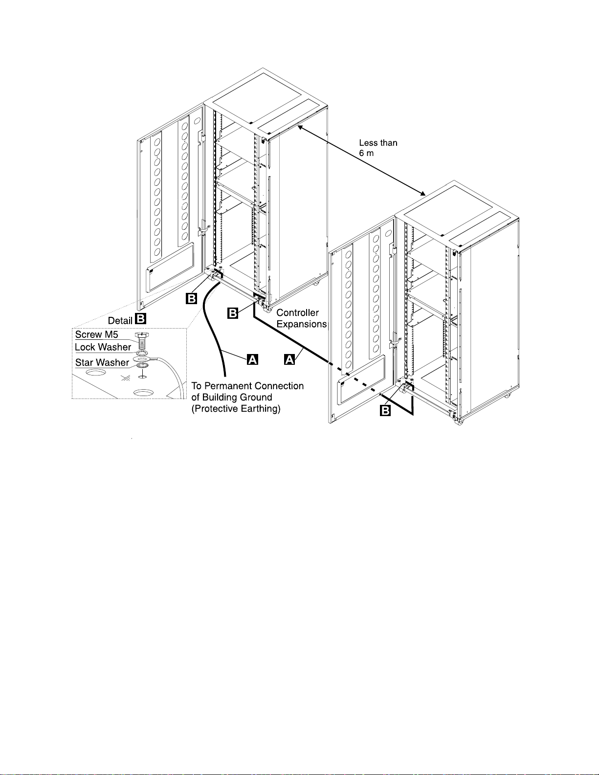
0-3. Ground Wire Connection Between Attached Controller Expansions . xxii
0-4. Ground Wire Connection Between Controller Expansions at Less
than Six Meters .............................. xxiii
0-5. Ground Wire Connection Between Controller Expansions at More
than Six Meters .............................. xxiv
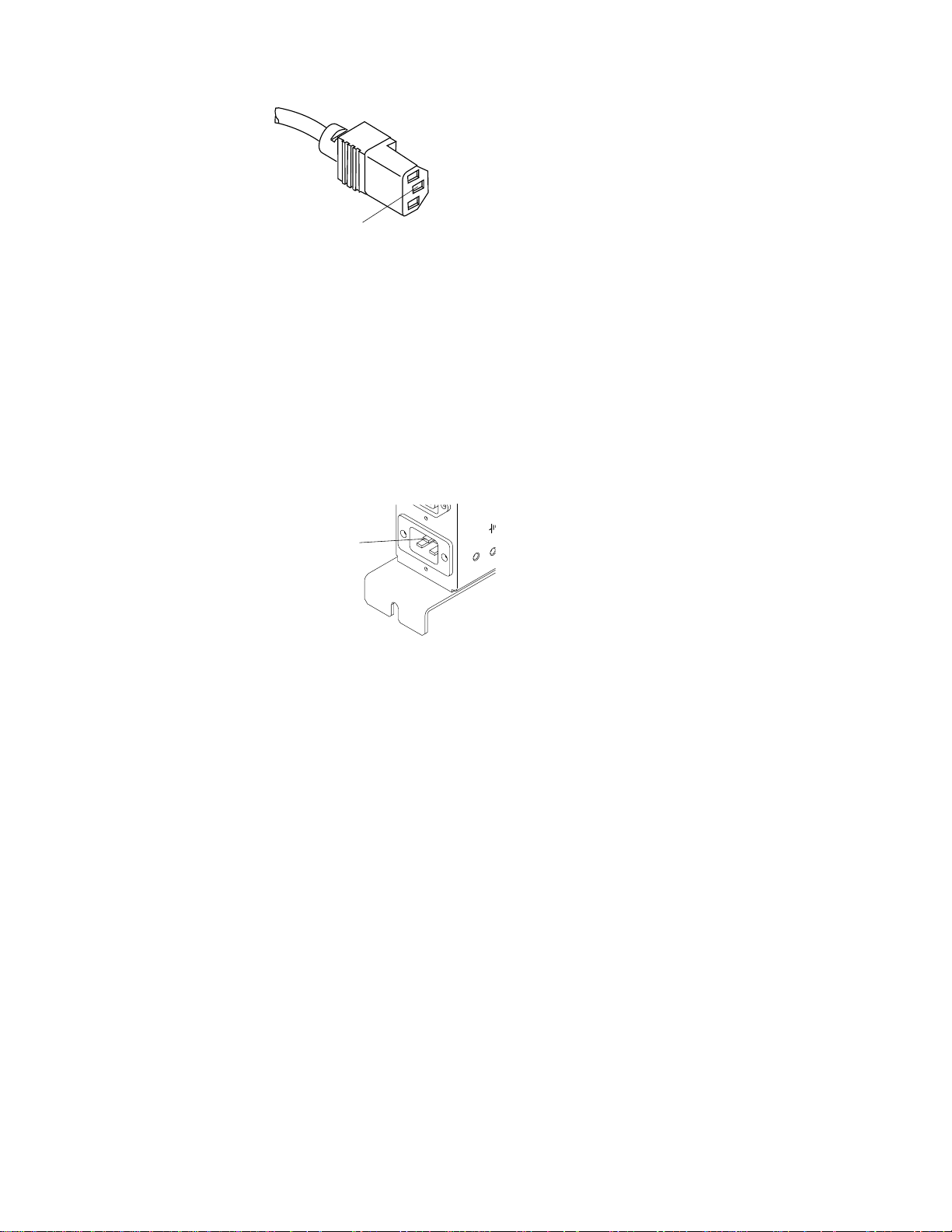
0-6. Ground Pin on Mainline ac/dc Power Cable ............... xxv
0-7. Ground Pin of the Controller Expansion ac Outlet Distribution Box .. xxv
0-8. LCB Grounding Via Screws ....................... xxvi
0-9. LCB Grounding Via Ground Wire .................... xxvi
0-10. Ground Wire Connection ......................... xxvii
0-11. Führung des Stromversorgungskabels bei der 3745/3746-900 ... xxxiii
0-12. Schutzleiteranschluß an der Erweiterung der Steuereinheit ..... xxxiv
0-13. Schutzleiteranschluß zwischen angeschlossenen Erweiterungen der
Steuereinheit. . . . . . . . . . . . . . . . . . . . . . . . . . . . . . . . . xxxv
0-14. Schutzleiteranschluß bei einem Abstand von weniger als 6 Meter
zwischen den Erweiterungen der Steuereinheit ............ xxxvi
0-15. Schutzleiteranschluß bei einem Abstand über 6 Meter zwischen den
Erweiterungen der Steuereinheit .................... xxxvii
0-16. Schutzleiterkontakt am Hauptstromversorgungskabel ........ xxxviii
0-17. Schutzleiterkontakt des Wechselstromverteilerkastens der
Erweiterung der Steuereinheit ..................... xxxviii
0-18. Erdung des Verteilerkastens über Schrauben ............. xxxix
0-19. Erdung des Verteilerkastens über Schutzleiter ............. xxxix
0-20. Schutzleiteranschluß . . . . . . . . . . . . . . . . . . . . . . . . . . . . . xl
0-21. 3745 Label and Power Rating Plate Locations (Back) ......... lvii
0-22. 3745 Label and Power Rating Plate Locations (Front) ......... lviii
0-23. 3746 Model 900 (Frame 07) Label Locations .............. lix
0-24. LCB Safety Label Location ......................... lix
0-25. 3745/3746-900 Safety Labels ........................ lx
0-26. 3745/3746-900 Safety Labels ....................... lxi
0-27. LCB Safety Label (PN 80G3928) ..................... lxii
0-28. Controller Expansion Power Rating Plate Location ........... lxii
1-1. Reference Code Screen ......................... 1-14
1-2. TSS Service Screen ............................ 1-63
1-3. Select/Release Screen . . . . . . . . . . . . . . . . . . . . . . . . . . 1-63
1-4. Mode Control Screen ........................... 1-64
1-5. TSS/HPTSS/ESS Diagnostic Selection Screen ............ 1-64
1-6. TRSS Service Screen ........................... 1-67
1-7. Select Screen . . . . . . . . . . . . . . . . . . . . . . . . . . . . . . . 1-67
1-8. Connect/Disconnect Screen . . . . . . . . . . . . . . . . . . . . . . . 1-68
1-9. TRSS Diagnostic Selection Screen ................... 1-68
1-10. TSS/HPTSS Diagnostic Selection Screen ............... 1-72
1-11. TSS Service Screen ............................ 1-74
1-12. Select/Release Screen . . . . . . . . . . . . . . . . . . . . . . . . . . 1-74
1-13. Mode Control Screen ........................... 1-75
1-14. LIC Types 1 and 4 Wrap Plug (PN 65X8927) ............. 1-75
1-15. LIC Type 3 Wrap Cable (PN 65X8928) ................. 1-75
1-16. LIC Types 5 and 6 Wrap Plug (PN 11F4815) ............. 1-76
Copyright IBM Corp. 1989, 1997 ix
Page 12

1-17. LIC Types 1, 3, and 4 ........................... 1-76
1-18. LIC Types 5 and 6 ............................. 1-77
1-19. 3745 Control Panel Layout ........................ 1-80
2-1. Console Outputs . . . . . . . . . . . . . . . . . . . . . . . . . . . . . . . 2-6
2-2. EPO Location 01S ............................. 2-16
2-3. UEPO Switch . . . . . . . . . . . . . . . . . . . . . . . . . . . . . . . . 2-21
2-4. EPO Location 01S ............................. 2-25
2-5. LAN Attached to the Service Processor ................ 2-42
3-1. CBA Diagnostic Coverage ......................... 3-3
3-2. Console Output . . . . . . . . . . . . . . . . . . . . . . . . . . . . . . . 3-6
3-3. Cable Configurations . . . . . . . . . . . . . . . . . . . . . . . . . . . . 3-7
3-4. Maintenance Functions Menu ....................... 3-9
3-5. How to Select Diagnostics ........................ 3-10
3-6. How to Enter Options ........................... 3-11
3-7. Error Menu . . . . . . . . . . . . . . . . . . . . . . . . . . . . . . . . . 3-12
3-8. LICs Type 1 and 4 (Wrap Plug PN 65X8927) ............. 3-23
3-9. LIC Type 3 (Wrap Cable PN 65X8928) ................. 3-23
3-10. LIC Types 1, 3, and 4 ........................... 3-23
3-11. LICs Type 5 and 6 (Wrap Plug PN 11F4815) ............. 3-24
3-12. LIC Types 5 and 6 ............................. 3-24
4-1. 3745 Frame (Front) ............................. 4-3
4-2. 3745 Frame (Back) ............................. 4-4
4-3. Card Locations . . . . . . . . . . . . . . . . . . . . . . . . . . . . . . . . 4-5
4-4. 3745 Model 17X Basic Board (without TPS, HPTSS, or ESS) ..... 4-6
4-5. 3745 Model 17X (Basic Board with TPS and HPTSS or ESS) .... 4-7
4-6. 3745 Model 130 (Basic Board with TPS) ................. 4-8
4-7. 3745 Model 150 (Basic Board) ....................... 4-9
4-8. 3745 Model 160 (Basic Board) ...................... 4-10
4-9. 3745 Models 130, 150, 160, and 170 (MOSS Board, Cards, and
Connectors) . . . . . . . . . . . . . . . . . . . . . . . . . . . . . . . . . 4-11
4-10. 3745 Model 17A (MOSS Board, Cards, and Connectors) ...... 4-12
4-11. 3745 LIC Unit Type 1 Board and Connectors (for LIC Types 1,3, and
4 in Models 150, 160, and 170) ..................... 4-13
4-12. 3745 LIC Unit Type 2 Board and Connectors (for LIC Types 5 and 6
in Models 150 and 170) .......................... 4-13
4-13. 3745 LIC Unit Type 3 Board and Connectors (for LIC Types 1,3, and
4 in Model 150) .............................. 4-14
4-14. 3745 LIC Board 01M-A2 Packaging ................... 4-15
4-15. 3745 LIC Board 01M-A1 Packaging ................... 4-16
4-16. 3745 LIC Board 01L-A2 Packaging ................... 4-17
4-17. 3745 LIC Board 01L-A2 Packaging (LICs Type 5) .......... 4-18
4-18. 3745 LIC Board 01L-A1 Packaging (LIC type 5) ............ 4-18
4-19. 3745 LIC Board 01L-A2 Packaging (LICs Type 6 Low Speed) ... 4-19
4-20. 3745 LIC Board 01L-A1 Packaging (LICs Type 6 Low Speed) ... 4-19
4-21. 3745 LIC Board 01L-A2 Packaging (LIC Type 6 High Speed) .... 4-20
4-22. 3745 LIC Board 01L-A1 Packaging (LIC Type 6 High Speed) .... 4-20
4-23. 3745 LIC Board 01M-A2 Packaging ................... 4-21
4-24. 3745 Ethernet Lines Tailgate ....................... 4-22
4-25. 3745 High-Speed Lines Tailgate ..................... 4-23
4-26. 3745 Token-Ring Tailgate ........................ 4-24
4-27. 3745 Channel Tailgate .......................... 4-25
4-28. 3745 Channel Tailgate Details. For more details see YZ052 Sheet
2. . . . . . . . . . . . . . . . . . . . . . . . . . . . . . . . . . . . . . . . 4-25
4-29. 3745 Models 1X0 Console Operator Tailgate ............. 4-26
x 3745 Models 130 to 17A: MIP
Page 13

4-30. 3745 Models 17A Console Operator Tailgate ............. 4-26
4-31. 3745 EPO . . . . . . . . . . . . . . . . . . . . . . . . . . . . . . . . . . 4-27
4-32. 3745 Control Panel ............................ 4-28
4-33. 3745 Flexible Diskette Drive ....................... 4-29
4-34. 3745 Hard Disk Drive ........................... 4-29
4-35. 3745 Primary Power Box Components ................. 4-30
4-36. 3745 Power Supply 1 Components ................... 4-31
4-37. 3745 Power Supply 2 Components ................... 4-32
4-38. 3745 Fan 1 Components ......................... 4-33
4-39. 3745 Fan 2 Components ......................... 4-33
4-40. CB1 Location. . . . . . . . . . . . . . . . . . . . . . . . . . . . . . . . 4-34
4-41. Covers . . . . . . . . . . . . . . . . . . . . . . . . . . . . . . . . . . . . 4-35
4-42. Shipping Springs . . . . . . . . . . . . . . . . . . . . . . . . . . . . . . 4-35
4-43. Channel Tailgate Location ........................ 4-36
4-44. Select Out Switch ............................. 4-36
4-45. Basic Board and CB1 Locations ..................... 4-38
4-46. Location of the LIC Boards ........................ 4-39
4-47. DMUX Cover . . . . . . . . . . . . . . . . . . . . . . . . . . . . . . . . 4-39
4-48. DMUX Location . . . . . . . . . . . . . . . . . . . . . . . . . . . . . . 4-40
4-49. DMUX . . . . . . . . . . . . . . . . . . . . . . . . . . . . . . . . . . . . 4-40
4-50. Location of the LIC Boards Type 2 ................... 4-41
4-51. SMUX Cover . . . . . . . . . . . . . . . . . . . . . . . . . . . . . . . . 4-41
4-52. SMUX Location . . . . . . . . . . . . . . . . . . . . . . . . . . . . . . 4-42
4-53. SMUX Link and Cable ........................... 4-42
4-54. Location of the LIC Boards ........................ 4-44
4-55. LIC 6 . . . . . . . . . . . . . . . . . . . . . . . . . . . . . . . . . . . . . 4-44
4-56. LIC Board Type 1 and 2 ......................... 4-45
4-57. LIC Board Type 3 ............................. 4-45
4-58. Panel, MOSS, and CB1 Locations .................... 4-46
4-59. MOSS Right Cover ............................ 4-46
4-60. Panel Cable Location on MOSS Board ................. 4-47
4-61. Panel . . . . . . . . . . . . . . . . . . . . . . . . . . . . . . . . . . . . 4-47
4-62. Panel Location . . . . . . . . . . . . . . . . . . . . . . . . . . . . . . . 4-48
4-63. Battery Location . . . . . . . . . . . . . . . . . . . . . . . . . . . . . . 4-48
4-64. Power Services Screen .......................... 4-49
4-65. Acknowledge Screen . . . . . . . . . . . . . . . . . . . . . . . . . . . 4-49
4-66. Fan 1 and CB1 Locations ......................... 4-50
4-67. Fan 1 Air Flow Detector and Power Cables .............. 4-50
4-68. Fan 2 and CB1 Locations ......................... 4-51
4-69. Fan 2 Air Flow Detector and Power Cables .............. 4-51
4-70. FDD and CB1 Location .......................... 4-52
4-71. PS1 . . . . . . . . . . . . . . . . . . . . . . . . . . . . . . . . . . . . . 4-53
4-72. MOSS Covers . . . . . . . . . . . . . . . . . . . . . . . . . . . . . . . 4-54
4-73. FDD Removal . . . . . . . . . . . . . . . . . . . . . . . . . . . . . . . 4-54
4-74. FDD Connectors . . . . . . . . . . . . . . . . . . . . . . . . . . . . . . 4-55
4-75. HDD and CB1 Locations ......................... 4-56
4-76. HDD Removal . . . . . . . . . . . . . . . . . . . . . . . . . . . . . . . 4-57
4-77. New Type of HDD ............................. 4-58
4-78. HDD Installation . . . . . . . . . . . . . . . . . . . . . . . . . . . . . . 4-58
4-79. HDD Connectors and Jumpers ...................... 4-60
4-80. HDD Connectors and Jumpers ...................... 4-60
4-81. Basic Board and CB1 Locations .................... 4-61
4-82. CB1 Location . . . . . . . . . . . . . . . . . . . . . . . . . . . . . . . . 4-62
4-83. Basic Board Grid .............................. 4-62
Figures xi
Page 14

4-84. Terminator Card Locations ........................ 4-62
4-85. CB1 Location . . . . . . . . . . . . . . . . . . . . . . . . . . . . . . . . 4-64
4-86. ESS Tailgate Location ........................... 4-64
4-87. ESS Tailgate and Basic board ...................... 4-65
4-88. ESS Cables . . . . . . . . . . . . . . . . . . . . . . . . . . . . . . . . . 4-65
4-89. EAC Card . . . . . . . . . . . . . . . . . . . . . . . . . . . . . . . . . . 4-65
4-90. Power Supply 1 (PS1) and CB1 Locations ............... 4-67
4-91. Power Supply 1 (PS1) Cover ....................... 4-67
4-92. Primary Power Box ............................ 4-68
4-93. Power Supply 1 .............................. 4-68
4-94. Primary Power Box, Power Supply 2, and CB1 Locations ...... 4-69
4-95. Cable Locations on Primary Power Box ................ 4-70
4-96. PS2 in Primary Power Box ........................ 4-70
4-97. PS2 and Primary Power Box Assembly ................. 4-71
4-98. Primary Power Box and CB1 Locations ................. 4-73
4-99. EPO Location . . . . . . . . . . . . . . . . . . . . . . . . . . . . . . . . 4-73
4-100. Cables on Primary Power Box ...................... 4-74
4-101. Primary Power Box and PS2 Cover Removal ............. 4-74
4-102. EPO Assembly . . . . . . . . . . . . . . . . . . . . . . . . . . . . . . . 4-75
4-103. Basic Board, MOSS Board, and CB1 Locations ............ 4-77
4-104. Basic Board and MOSS Covers ..................... 4-78
4-105. Basic Board Grid .............................. 4-78
4-106. FDS and Multivoltage Cable Locations on the PS1 .......... 4-78
4-107. Fan2 Air Flow Detector and Power Connectors ............ 4-79
4-108. MOSS to Basic Cable Locations ..................... 4-79
4-109. Basic Board Enclosure .......................... 4-79
4-110. Basic Board Cables ............................ 4-80
4-111. Basic Assembly 1 ............................. 4-81
4-112. Basic Assembly 2 ............................. 4-82
4-113. Y and Z Rows ............................... 4-83
4-114. CB1 Location . . . . . . . . . . . . . . . . . . . . . . . . . . . . . . . . 4-84
4-115. LIC Board Type 1 Locations ....................... 4-84
4-116. DMUX Cover . . . . . . . . . . . . . . . . . . . . . . . . . . . . . . . . 4-85
4-117. LIC Locations . . . . . . . . . . . . . . . . . . . . . . . . . . . . . . . . 4-86
4-118. LIC Board Assembly ............................ 4-87
4-119. CB1 Location . . . . . . . . . . . . . . . . . . . . . . . . . . . . . . . . 4-88
4-120. SMUX Cover . . . . . . . . . . . . . . . . . . . . . . . . . . . . . . . . 4-88
4-121. LIC Board Type 2 Locations ....................... 4-89
4-122. SMUX Link and Cable ........................... 4-89
4-123. LIC Locations . . . . . . . . . . . . . . . . . . . . . . . . . . . . . . . . 4-90
4-124. LIC Board Assembly ............................ 4-90
4-125. MOSS Board and CB1 Locations .................... 4-92
4-126. MOSS Board Covers ........................... 4-92
4-127. MOSS Board Cards and Cables ..................... 4-93
4-128. MOSS Board Enclosure .......................... 4-94
4-129. CB1 Location . . . . . . . . . . . . . . . . . . . . . . . . . . . . . . . . 4-96
4-130. Select Out Switch ............................. 4-96
4-131. Channel Tailgate and Basic Board Grid ................ 4-97
4-132. Channel Tailgate, Cables, and Basic Board .............. 4-97
xii 3745 Models 130 to 17A: MIP
Page 15

Tables
0-1. Part Numbers . . . . . . . . . . . . . . . . . . . . . . . . . . . . . . . . xxviii
0-2. ac Input Adjustment ............................ xxviii
0-3. LED Status Versus 3746-900 States ................... xxx
0-4. 3745 Power Supply CP/CB and Fuse Reference ............ xxx
0-5. Teilenummern . . . . . . . . . . . . . . . . . . . . . . . . . . . . . . . . xli
0-6. Einstellung der Spannung des Wechselstromeingangs ......... xli
0-7. Bedeutung der LEDs am Bedienungsfeld der 3746-900 ........ xlii
0-8. Stromversorgung der 3745, Sicherungsautomaten (CB),
Überstromschutzschalter (CP) und Sicherungen (F) .......... xliii
0-9. Safety Label Numbers by Country ..................... lxiii
1-1. General Symptoms . . . . . . . . . . . . . . . . . . . . . . . . . . . . . 1-8
1-2. 3745 Console Symptoms ......................... 1-10
1-3. Control Panel Symptoms ......................... 1-11
1-4. Power Symptoms . . . . . . . . . . . . . . . . . . . . . . . . . . . . . 1-12
1-5. Panel Codes . . . . . . . . . . . . . . . . . . . . . . . . . . . . . . . . 1-15
1-6. 3745 FRU Table .............................. 1-49
1-7. 3745 Cable Location ........................... 1-52
1-8. 3745 Diagnostic Requirements ...................... 1-60
1-9. Diagnostic Selection . . . . . . . . . . . . . . . . . . . . . . . . . . . . 1-65
1-10. Panel Display Values ........................... 1-81
2-1. Wrap plug PN ................................ 2-6
2-2. 3745 Control Panel Code ......................... 2-32
2-3. Icons Color Selection Table ....................... 2-38
3-1. Wrap Plugs for Testing ARC Assembly A and ARC Assembly B (with
Cable) . . . . . . . . . . . . . . . . . . . . . . . . . . . . . . . . . . . . 3-22
3-2. Wrap Plugs for LIC Testing ........................ 3-22
3-3. Wrap Plugs for Testing ARC Assembly B (without Cable) ...... 3-22
4-1. TIC Position and Ring Address ...................... 4-5
4-2. Basic Board Configurations ......................... 4-6
4-3. DMUX Packaging . . . . . . . . . . . . . . . . . . . . . . . . . . . . . 4-14
4-4. SMUX Packaging . . . . . . . . . . . . . . . . . . . . . . . . . . . . . 4-14
4-5. 3745 Ethernet Line Locations ...................... 4-22
4-6. 3745 High-Speed Line Locations .................... 4-23
4-7. 3745 Token-ring Line Locations ..................... 4-24
4-8. Channel Interface . . . . . . . . . . . . . . . . . . . . . . . . . . . . . 4-25
4-9. 3745 Power Supply Cross Reference .................. 4-31
4-10. Select Out Switches According to CADR Cards ............ 4-36
4-11. Voltage Test Points ............................ 4-53
B-1. Customer Documentation for the 3745 Models 130 to 17A and 3746
Model 900 . . . . . . . . . . . . . . . . . . . . . . . . . . . . . . . . . . B-2
B-2. Service Documentation for the 3745 Models 1x0 and 17A, and 3746
Model 900 . . . . . . . . . . . . . . . . . . . . . . . . . . . . . . . . . . B-6
Copyright IBM Corp. 1989, 1997 xiii
Page 16

xiv 3745 Models 130 to 17A: MIP
Page 17

Notices
References in this publication to IBM products, programs, or services do not imply
that IBM intends to make these available in all countries in which IBM operates.
Any reference to an IBM product, program, or service is not intended to state or
imply that only IBM's product, program, or service may be used. Any functionally
equivalent product, program, or service that does not infringe any of IBM's intellectual property rights may be used instead of the IBM product, program, or service.
Evaluation and verification of operation in conjunction with other products, except
those expressly designated by IBM, is the user's responsibility.
IBM may have patents or pending patent applications covering subject matter in
this document. The furnishing of this document does not give you any license to
these patents. You can send license inquiries, in writing, to the IBM Director of
Licensing, IBM Corporation, 500 Columbus Avenue, Thornwood, New York 10594,
U.S.A.
European Union (EU) Statement
This product is in conformity with the protection requirements of EU Council Directive 89/336/EEC on the approximation of the laws of the Member States relating to
electromagnetic compatibility. IBM can not accept responsibility for any failure to
satisfy the protection requirements resulting from a non-recommended modification
of the product, including the fitting of non-IBM option cards.
Electronic Emission Notices
Federal Communications Commission (FCC) Statement
Note: This equipment has been tested and found to comply with the limits for a
Class A digital device, pursuant to Part 15 of the FCC Rules. These limits are
designed to provide reasonable protection against harmful interference when the
equipment is operated in a commercial environment. This equipment generates,
uses, and can radiate radio frequency energy and, if not installed and used in
accordance with the instruction manual, may cause harmful interference to radio
communications. Operation of this equipment in a residential area is likely to cause
harmful interference, in which case the user will be required to correct the interference at his own expense.
Properly shielded and grounded cables and connectors must be used in order to
meet FCC emission limits. IBM is not responsible for any radio or television interference caused by using other than recommended cables and connectors or by
unauthorized changes or modifications to this equipment. Unauthorized changes or
modifications could void the user's authority to operate the equipment.
This device complies with Part 15 of the FCC Rules. Operation is subject to the
following two conditions: (1) this device may not cause harmful interference, and
(2) this device must accept any interference received, including interference that
may cause undesired operation.
Copyright IBM Corp. 1989, 1997 xv
Page 18

Industry Canada Compliance Statement
This Class A digital apparatus meets all requirements of the Canadian InterferenceCausing Equipment Regulations.
Avis de conformité aux normes d'Industrie Canada
Cet appareil numérique de la classe A respecte toutes les exigences du Règlement
sur le matériel brouilleur du Canada.
Japanese Voluntary Control Council For Interference (VCCI) Statement
This equipment is in the 1st Class category (information equipment to be used in
commercial and/or industrial areas) and conforms to the standards set by the Voluntary Control Council for Interference by Information Technology Equipment aimed
at preventing radio interference in commercial and industrial areas.
Consequently, when used in a residential area or in an adjacent area thereto, radio
interference may be caused to radios and TV receivers, and so on.
Read the instructions for correct handling.
Korean Communications Statement
Please note that this device has been approved for business purpose with regard to
electromagnetic interference. If you find this is not suitable for your use, you may
exchange it for a non-business one.
New Zealand Radiocommunications (Radio) Regulations
Attention: This is a Class A product. In a domestic environment this product may
cause radio interference in which case the user may be required to take adequate
measures.
Trademarks and Service Marks
The following terms, denoted by an asterisk (*), used in this publication, are trademarks or service marks of IBM Corporation in the United States or other countries:
ESCON IBM OS/2
NetView RETAIN
The following terms, denoted by a double asterisk (**), used in this publication, are
trademarks of other companies:
Hayes Hayes Microcomputer Products, Inc.
Tektronix Tektronix, Incorporated.
xvi 3745 Models 130 to 17A: MIP
Page 19

Safety
Product Safety Information
General Safety
This product meets IBM safety standards.
For more information, see the following manual:
IBM 3745 Communication Controller All Models
IBM 3746 Nways Multiprotocol Controller Models 900 and 950
Safety Information
Service Inspection Safety Procedures
, GA33-0400.
Service Inspection Safety Procedures for the 3745, 3746-900, and Controller Expansion English
Sicherheitsüberprüfungen für IBM 3745, 3746-900 und die Erweiterung der Steuereinheit Deutsch
xviii
xxxi
xliii
Copyright IBM Corp. 1989, 1997 xvii
Page 20

Service Inspection Safety Procedures for the 3745, 3746-900, and
Controller Expansion
Important
This procedure addresses the 3745, 3746-900, and the controller expansion. If one of these machines
is not present, ignore the statement concerning this machine in the following procedure.
Introduction
A safety inspection procedure for the 3745, 3746-900, and controller expansion should be performed:
When it is inspected for an IBM agreement
When IBM service is requested and no service has recently been performed by IBM
When an alterations and attachments review is performed
When changes have been made to the equipment that might affect its safety.
If the inspection indicates unacceptable safety conditions, the conditions must be corrected before IBM
services the machine.
Note: The correction of any unsafe condition is the responsibility of the owner of the equipment.
Safety
The 3745, 3746-900, and controller expansion areas and functions checked through these procedures are:
1. External covers
2. Safety labels
3. Safety covers and shields
4. Grounding (earthing)
5. Circuit breaker and protector rating
6. Input power voltage
7. Power control switch
8. Power ON indicator.
Note: The 3746-900 is powered ON and OFF through the basic 3745 frame, from a host, locally, or from
the service processor.
Hazardous voltages are still present in some areas of the 3745 and the 3746-900 when power is
OFF.
Steps 1 through 6 must be performed after power OFF as follows:
CB1s are switched OFF on the 3745 and 3746-900.
All equipment installed in the controller expansion (if present) is powered OFF.
Power supplies for the 3745, 3746-900, and controller expansion at customer's premises are
switched OFF.
Do not remove the power cord and ground strap .A/ of the controller expansion in order to maintain
the ground protection (see Figure 0-2 on page xxi, Figure 0-3 on page xxii, Figure 0-4 on page xxiii,
or Figure 0-5 on page xxiv).
1External Covers
Check that:
They are all present on the 3745, 3746-900, and controller expansion.
They are locked with two kinds of locks: flat blade screw for the IBM access area and hex head
for the customer access area (refer to the
17A, Parts Catalog
They can be fully opened.
, S135-2012).
xviii 3745 Models 130 to 17A: MIP
IBM 3745 Communication Controller Models 130 to
Page 21

Safety
Appropriate service clearance and access are provided around the frames with external covers
opened.
Leave all external covers opened to allow further safety inspection steps.
2Safety Labels
Check that:
All the safety labels are at the places indicated by letters in “Safety Label Locations” on
page lvii.
Each label is of the model corresponding to the letter as shown in “3745/3746-900 Safety Label
Identifications” on page lx.
3 Safety Covers and Shields
Referring to the FRU location (Chapter 4), check that:
All the safety covers are present and secured with screws.
All the voltage terminal boards (TBs) are protected by a plastic shield screwed on top of the TB.
4Grounding (Earthing)
Note
In this book, "ground" means that the equipment must be connected to the earth.
a Grounding on the 3745
Refer to YZ110 for grounding jumper/contact locations. .
Check that:
Electrical continuity is assured between the frame ground and the terminals indi-
cated on the ground distribution diagrams.
Electrical continuity is assured between the 3745, frame grounds, and to the premises
grounding system, through the 3745 power cord.
b Grounding on the 3746-900 and Controller Expansion to the Premises Grounding
System
Electrical continuity is assured between their frame ground and premises grounding
system through their power cords.
The 3746-900 is grounded to the 3745 via the power control cable (see Figure 0-1 on
page xx).
For the controller expansion, an additional ground wire .A/ is also used (see Figure 0-2 on
page xxi, Figure 0-3 on page xxii, Figure 0-4 on page xxiii, or Figure 0-5 on page xxiv).
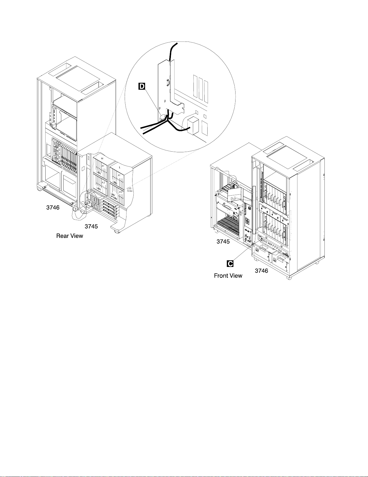
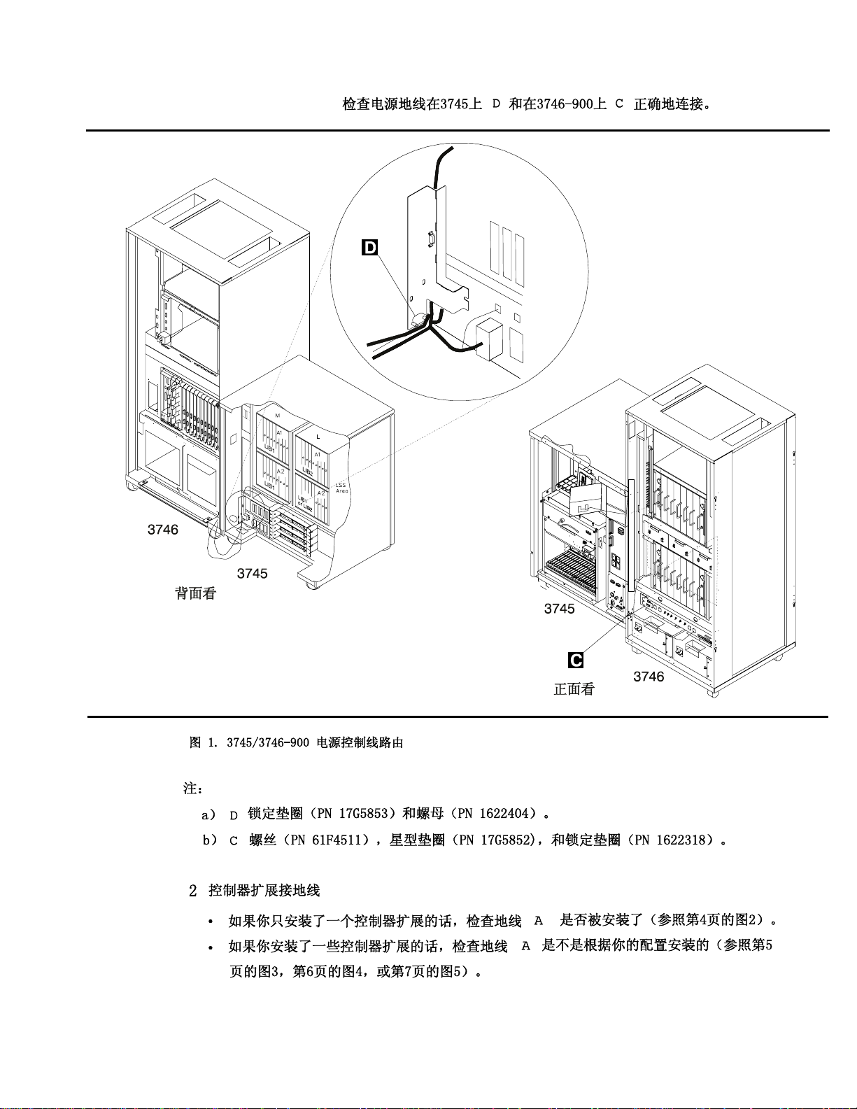
1 3745/3746-900 Power Control Cable
Check that the power ground cable is correctly connected in the 3745 .D/ and in the
3746-900 .C/.
Safety xix
Page 22
Safety
Figure 0-1. 3745/3746-900 Power Control Cable Routing
Notes:
a) .D/Lock washer (PN 17G5853) and nut (PN 1622404).
b) .C/Screw (PN 61F4511), star washer (PN 17G5852), and lock washer
(PN 1622318).
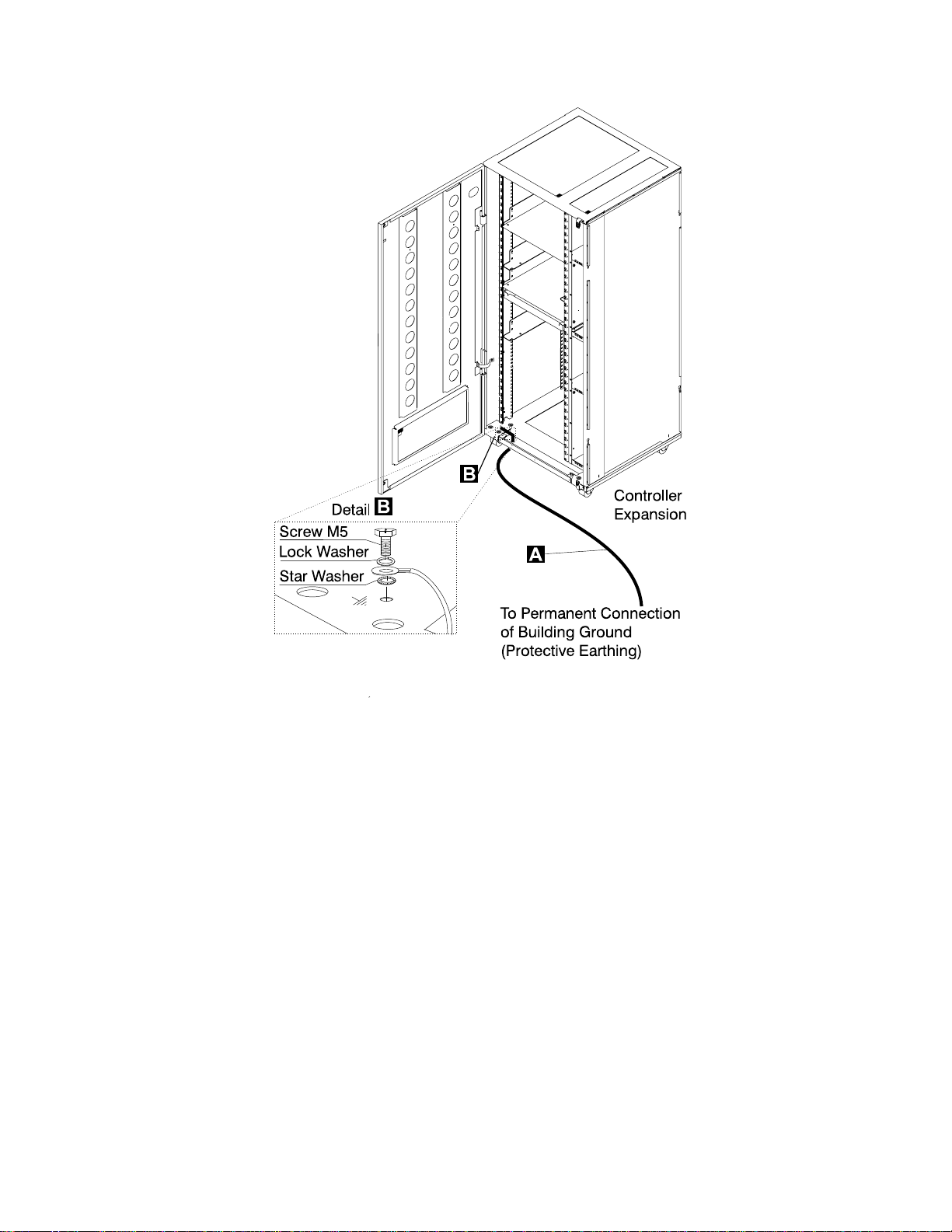
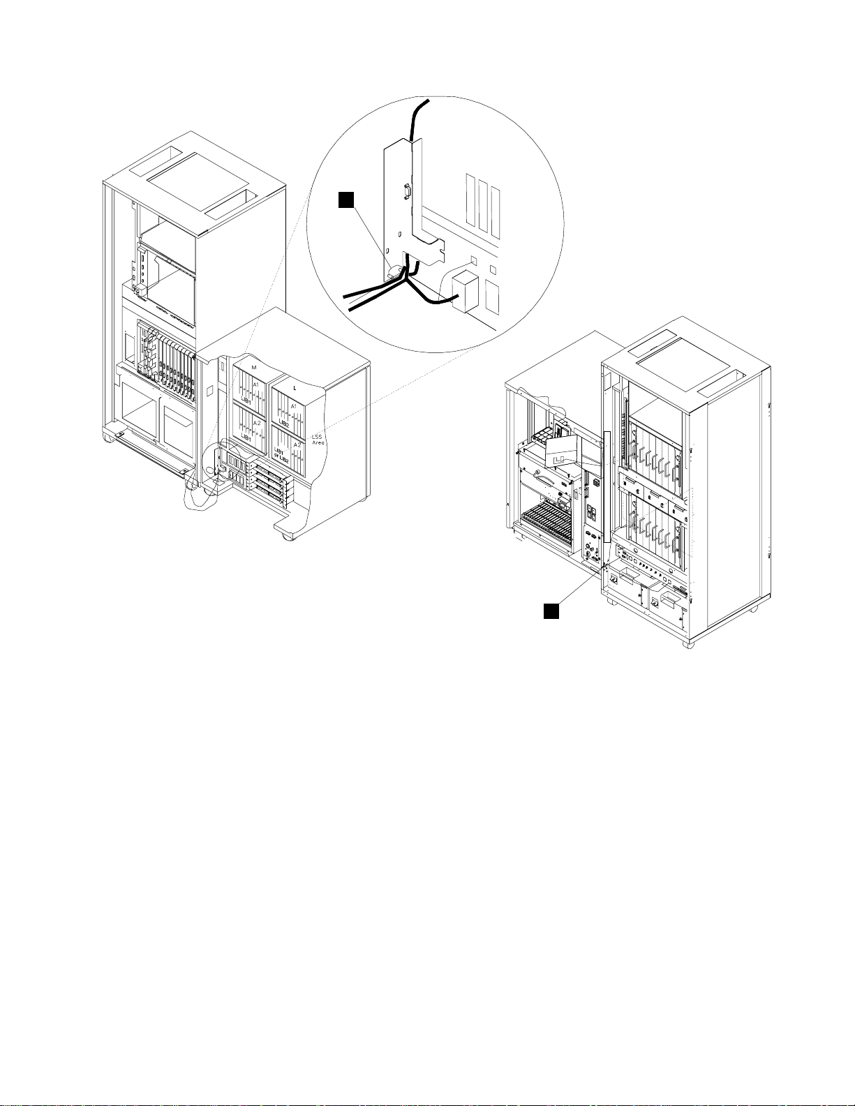
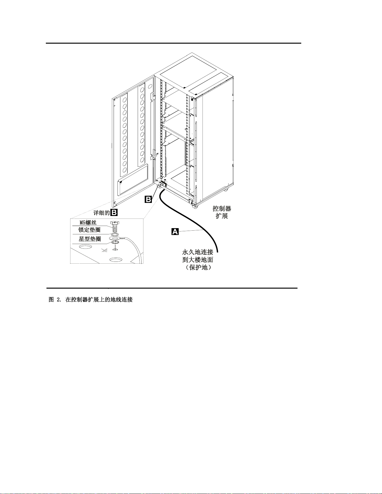
2 Controller Expansion Ground Wire Cable
If you have only one controller expansion installed, check that the ground wire .A/ is
installed (see Figure 0-2 on page xxi).
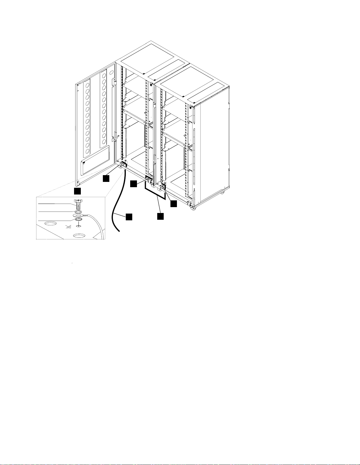
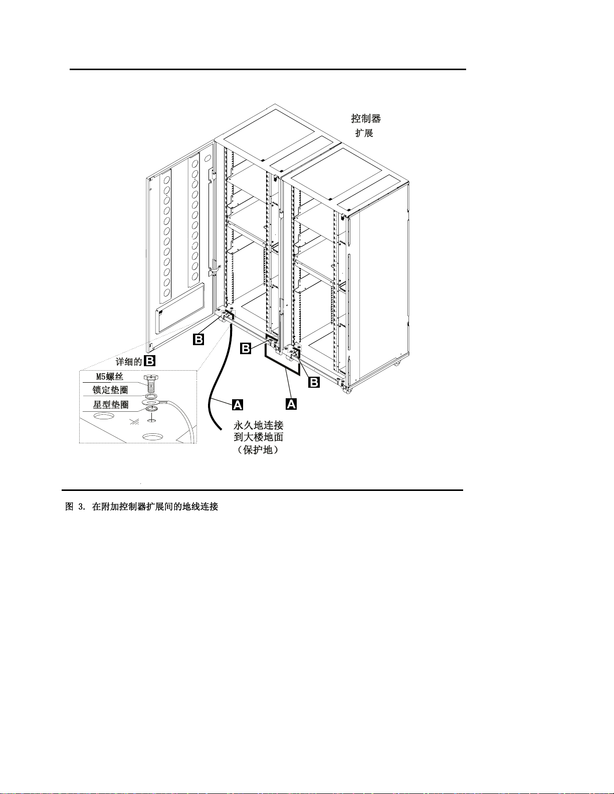
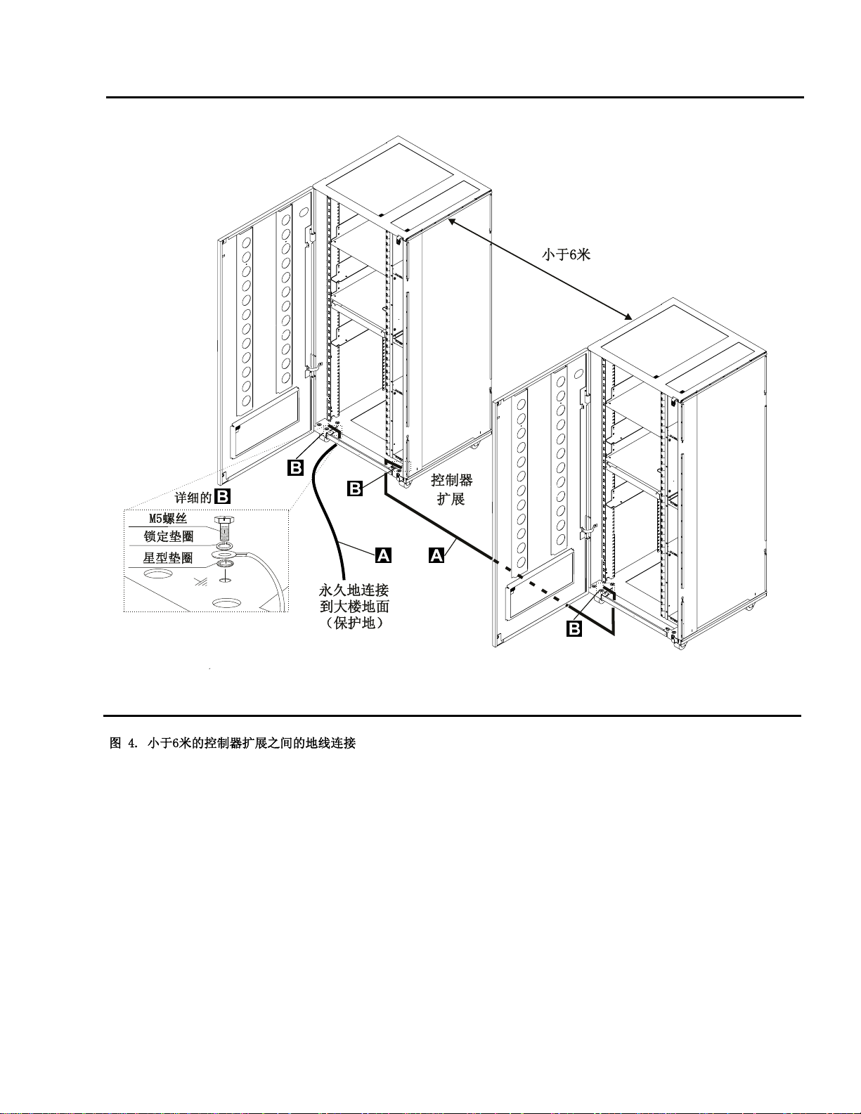
If you have several controller expansions installed, check that the ground wires .A/
are installed according to your configuration (see Figure 0-3 on page xxii,
Figure 0-4 on page xxiii, or Figure 0-5 on page xxiv).
xx 3745 Models 130 to 17A: MIP
Page 23
Safety
Figure 0-2. Ground Wire Connection on Controller Expansion
Safety xxi
Page 24
Controller
Expansion
Safety
B
B
B
Detail
Screw M5
Lock Washer
Star Washer
A
Figure 0-3. Ground Wire Connection Between Attached Controller Expansions
A
To Permanent Connection
of Building Ground
(Protective Earthing)
B
A
xxii 3745 Models 130 to 17A: MIP
Page 25
Safety
Figure 0-4. Ground Wire Connection Between Controller Expansions at Less than Six Meters
Safety xxiii
Page 26
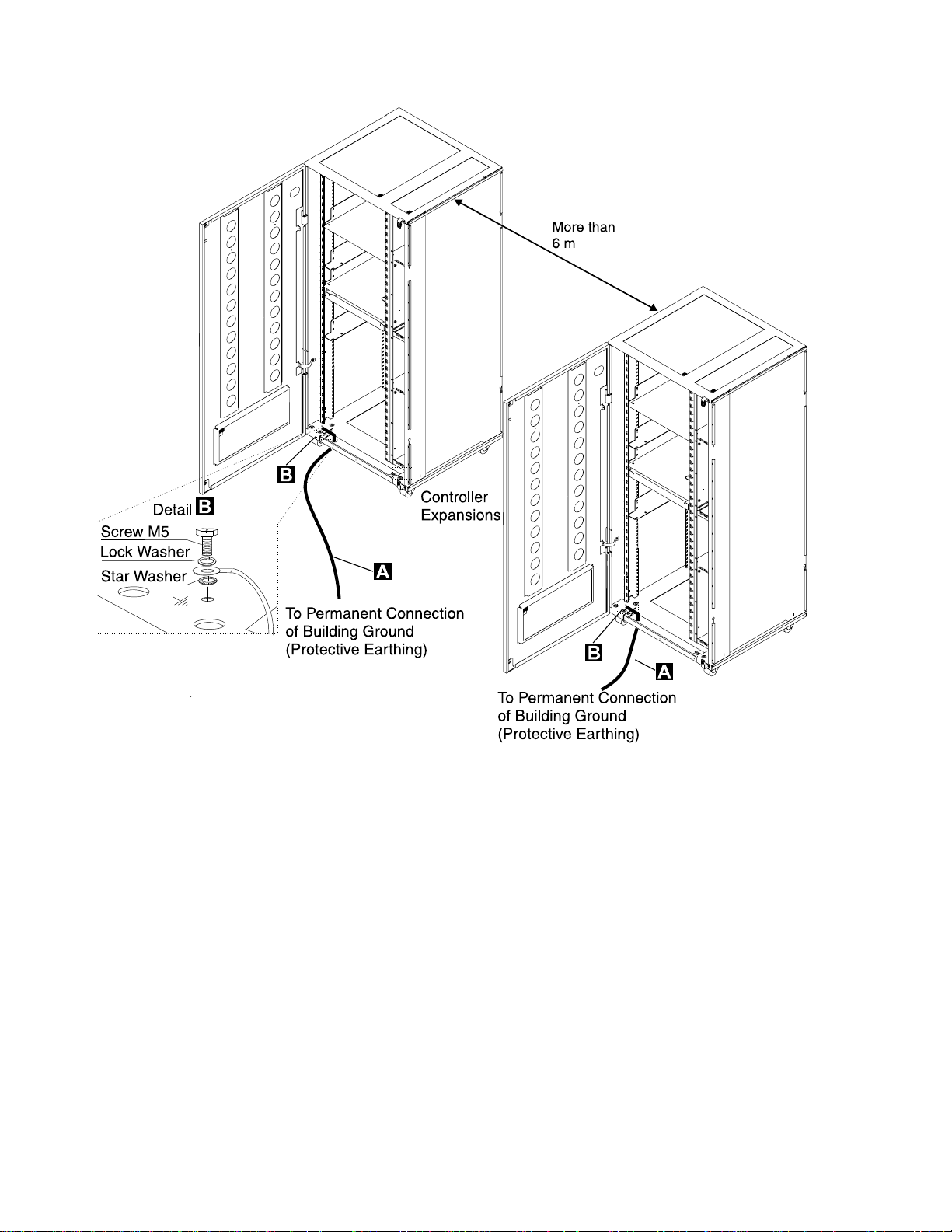
Safety
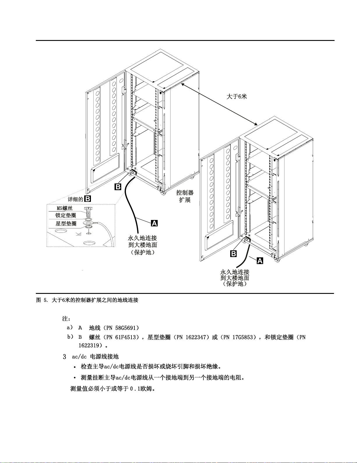
Figure 0-5. Ground Wire Connection Between Controller Expansions at More than Six Meters
Notes:
a) .A/Ground wire (PN 58G5691)
b) .B/Screw (PN 61F4513), star washer (PN 1622347) or (PN 17G5853), and lock
washer (PN 1622319).
3 ac/dc Power Cable Ground Wire
Check the mainline ac/dc power cable for damaged or burned pins and broken insu-
lation.
Measure the resistance of the disconnected mainline ac/dc power cable from ground
pin on one end to the ground pin on the other end.
The measurement should be 0.1 ohm or less.
xxiv 3745 Models 130 to 17A: MIP
Page 27
Safety
Ground Pin
Figure 0-6. Ground Pin on Mainline ac/dc Power Cable
c Internal Grounding in the 3746-900 and Controller Expansion
On the 3746-900
Check that electrical continuity is assured between the LCB housing and 3746-900 frame,
if LCBs are present. This operation must be performed before any network connection.
On the Controller Expansion
Check that electrical continuity is assured between each machine installed in the controller
expansion (service processor, network node processor, modem, optical disk drive, and so
on) and the ground pin of the ac outlet distribution box (see Figure 0-7).
Check that electrical continuity is assured between the ground pin of the ac outlet distrib-
ution box and the controller expansion mount frame.
Ground Pin
Figure 0-7. Ground Pin of the Controller Expansion ac Outlet Distribution Box
Check that electrical continuity is assured between the LCB housing and the controller
expansion frame, if LCBs are present. This operation must be performed before any
network connection (see Figure 0-8 on page xxvi).
Note: All the previous measurements should indicate 0.1 ohm or less.
d Grounding of Line Connection Boxes (LCBs) not Installed in the 3746-900 or Controller
Expansion
Check that electrical continuity is assured between the LCB housing and the premises
grounding system.
There are two ways to ensure proper grounding of the LCB depending on where it is installed:
1) Grounding is ensured by the four screws which secure the LCB on the rack if the frame of
the rack is connected to the premises ground system.
Safety xxv
Page 28
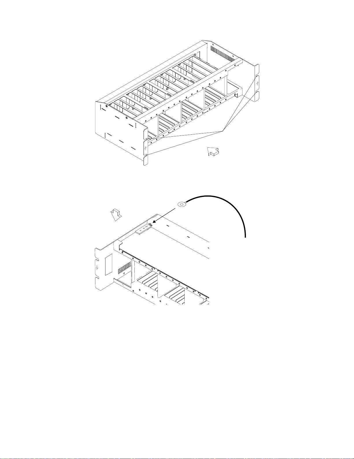
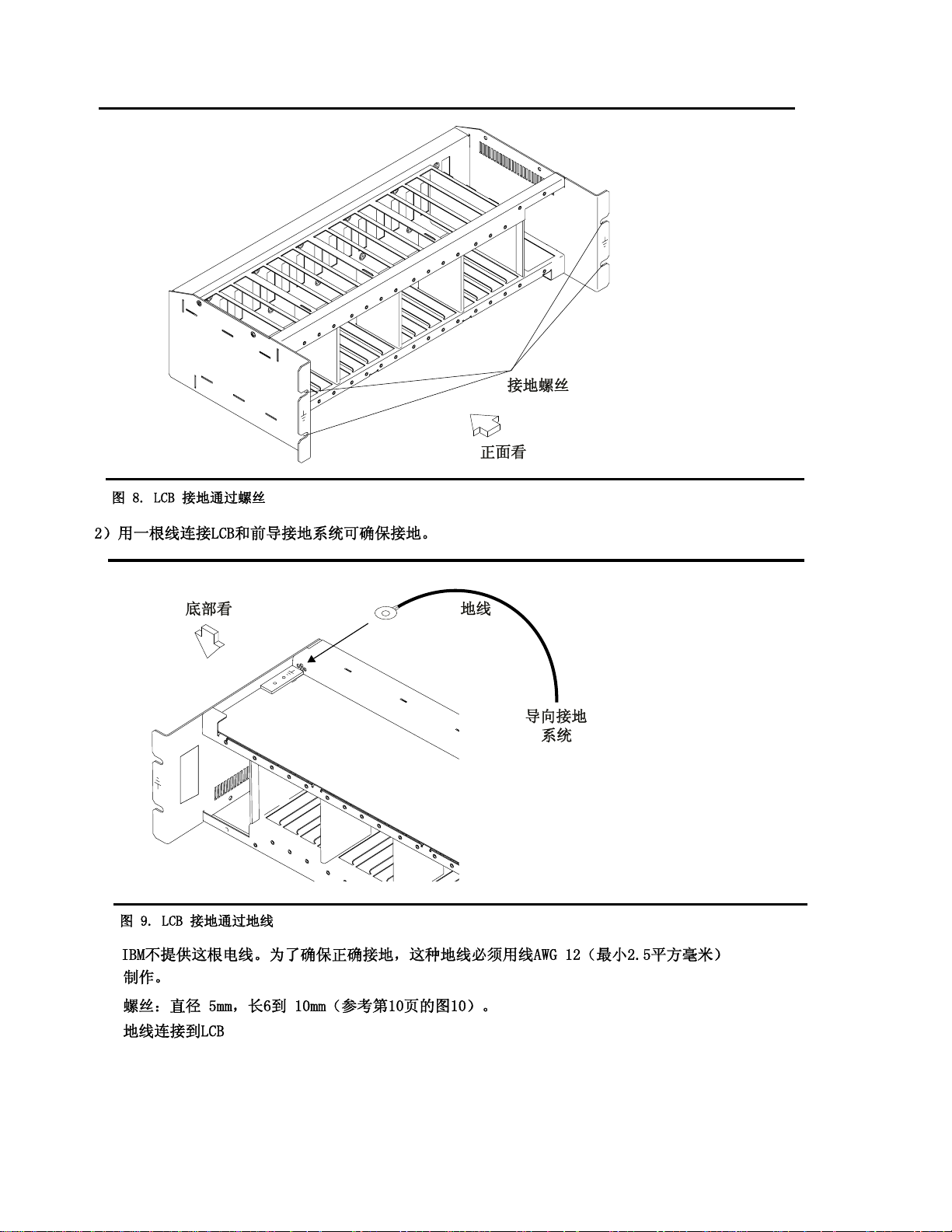
Figure 0-8. LCB Grounding Via Screws
Safety
Screws for
Grounding
Front View
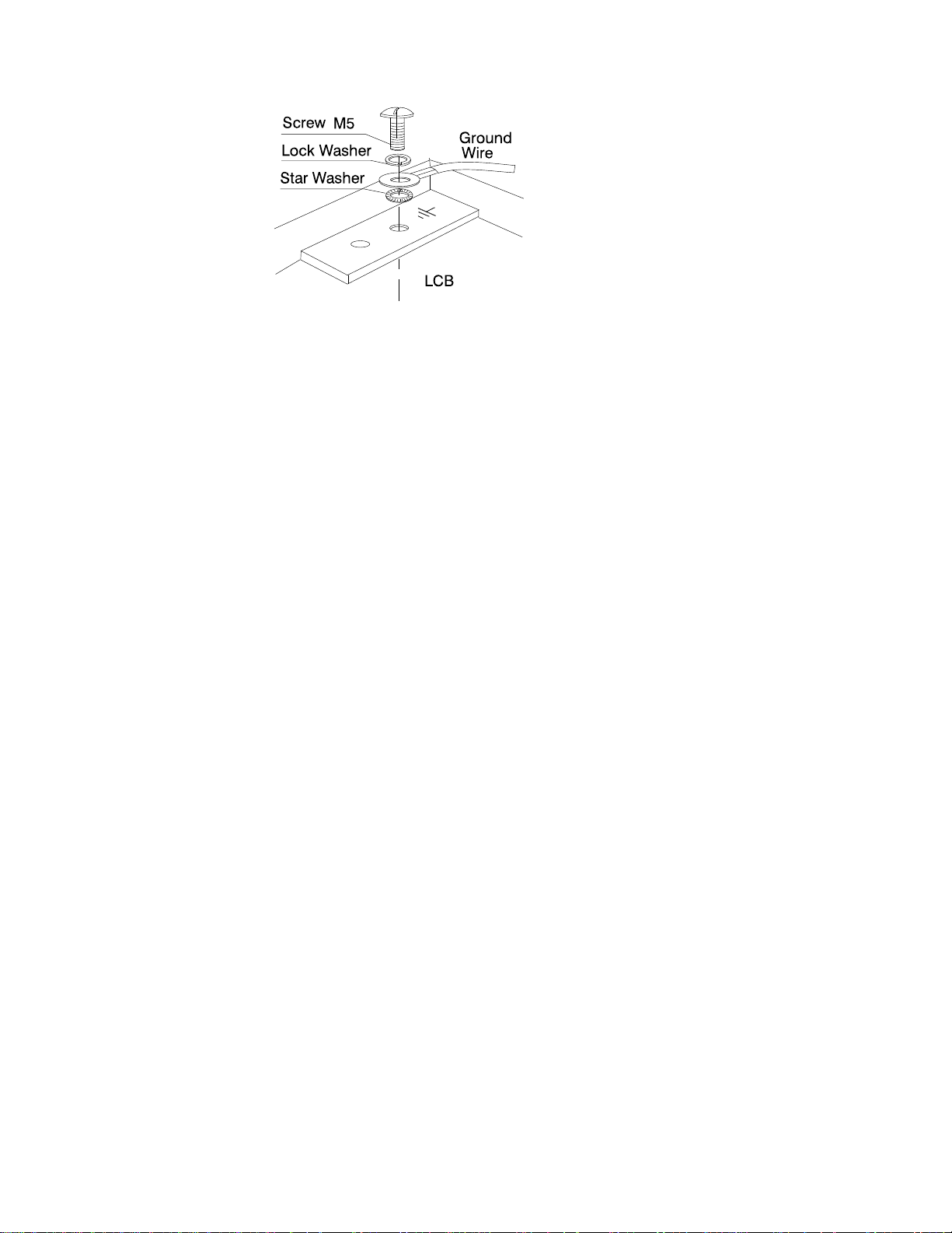
2) Grounding is ensured by a wire connected from the LCB to the premises ground system.
BottomView
Ground
Wire
ToPremises
Grounding
System
Figure 0-9. LCB Grounding Via Ground Wire
IBM does not provide this wire. In order to ensure correct grounding, this ground wire
must be made using a wire AWG 12 (minimum 2.5 square millimeters).
Screw: 5 mm in diameter, length from 6 to 10 mm (refer to Figure 0-10 on page xxvii).
Connection of Ground Wire to LCB
xxvi 3745 Models 130 to 17A: MIP
Page 29
Safety
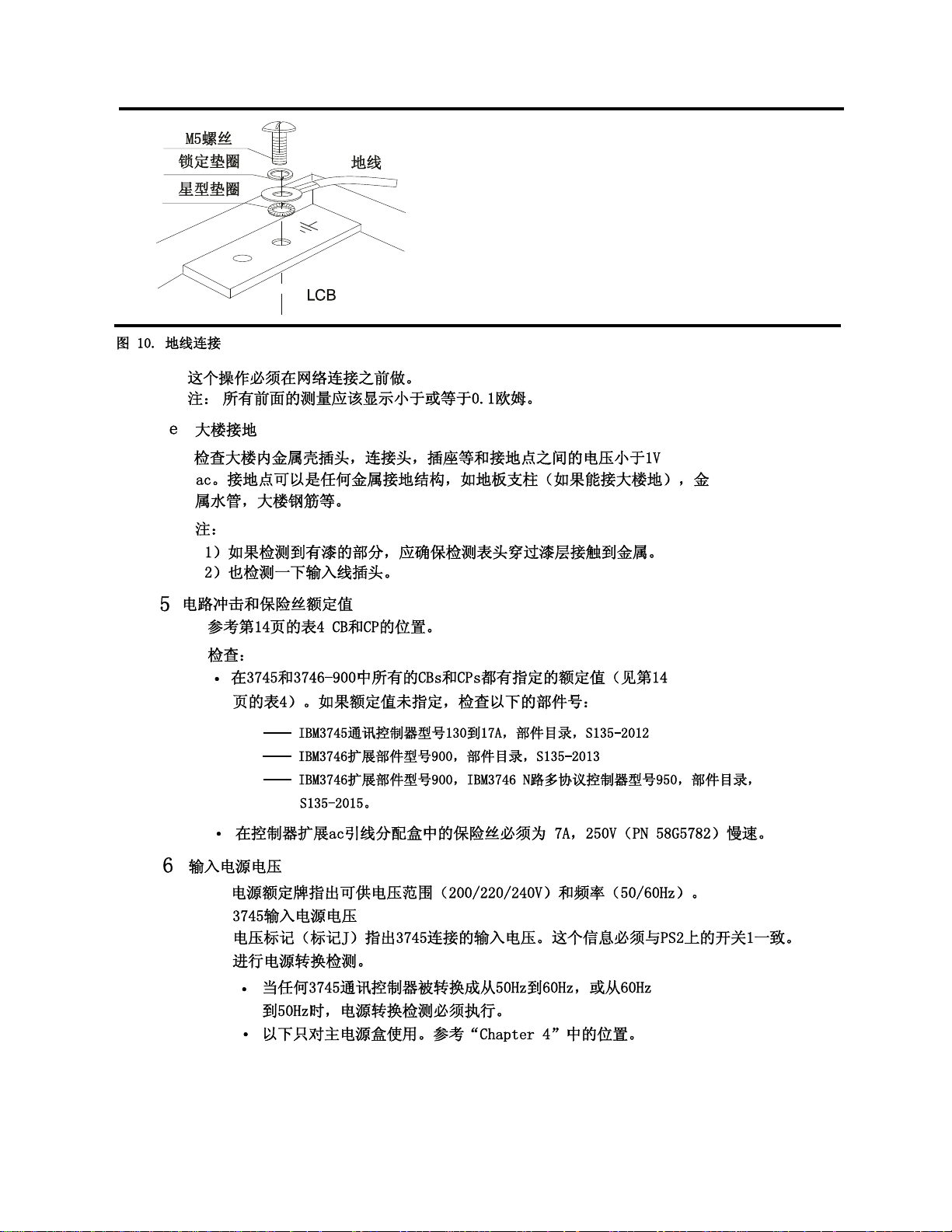
Figure 0-10. Ground Wire Connection
This operation must be performed before any network connection.
Note: All the previous measurements should indicate 0.1 ohm or less.
eBuilding Grounding
Check that there is less than 1 V ac between the metal housings of plugs, connec-
tors, receptacles, and so on., and any grounded point in the building. This can be
any grounded metal structure, such as the stanchions of a raised floor (if they are
electrically connected to building ground), a metal water pipe, building steel, and so
on.
Notes:
1) When probing a painted metal part, ensure that the meter probe tip penetrates the
paint.
2) Also check plugs of incoming cables.
5 Circuit Breaker and Protector Rating
Refer to Table 0-4 on page xxx for CB and CP locations.
Check that:
All CBs and CPs in the 3745 and 3746-900 are rated at the indicated value in Table 0-4 on
page xxx. If the rating is not indicated, check the part number against one of the following:
–
IBM 3745 Communication Controller Models 130 to 17A, Parts Catalog
–
IBM 3746 Expansion Unit Model 900, Parts Catalog
–
IBM 3746 Nways Multiprotocol Controller Models 900 and 950, Parts Catalog
The fuses in the controller expansion ac outlet distribution box must be 7 A, 250 V slow
(PN 58G5782).
, S135-2013
, S135-2012
, S135-2015.
6 Input Power Voltage
The power rating plate indicates the voltage range available (200/220/240) and the frequency
(50/60 Hz).
3745 Input Power voltage
The voltage label (label J) indicates the input voltage for which the 3745 is wired. This information
must be in accordance with Switch 1 on PS2.
Performing a power conversion Inspection.
A power conversion inspection must be performed on any 3745 Communication Controller that
has been converted from 50 Hz to 60 Hz, or from 60 Hz to 50 Hz.
The following is used only for the primary power box. Refer to Figure 4-1 on page 4-3 for
location.
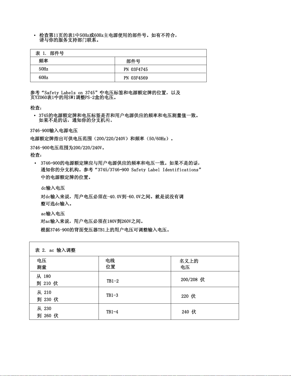
Check Table 0-1 on page xxviii for the correct part numbers for the specified 50 Hz or 60 Hz
use. In case of discrepancy, contact your support structure.
Safety xxvii
Page 30

Table 0-1. Part Numbers
Frequencies Part Numbers
50 Hz PN 03F4745
60 Hz PN 03F4569
Refer to Figure 0-21 on page lvii for voltage label and power rating plate location, and to page
YZ060, sheet 1 for the PS2 box voltage adjustment by SW1.
Check that:
The power rating plate and the voltage label of the 3745 are consistent with the frequency and
the voltage measured at the customer's power supply. If they are inconsistent, inform your
branch office.
3746-900 Input Power voltage
The power rating plate indicates the voltage range available (200/220/240) and the frequency
(50/60&rlb.Hz).
The 3746-900 voltage range is 200/220/240.
Check that:
The power rating plate of the 3746-900 is consistent with the frequency and the voltage meas-
ured at the customer's power supply. If they are inconsistent inform your branch office. Refer to
“3745/3746-900 Safety Label Identifications” on page lx for the power rating plate location.
dc Input Voltage
For dc input, the customer's voltage must be within -40.0 V to -60.0 V. There is no adjustment
for the optional dc input.
ac Input Voltage
For ac input, the customer's voltage must be within 180 V to 260 V.
Adjustment of the input voltage can be done according to the customer voltage on TB1 of the
transformers located at the rear of the 3746-900.
Safety
Table 0-2. ac Input Adjustment
Voltage
Measured
From 180
to 210 Volts
From 210
to 230 Volts
From 230
to 260 Volts
Important Note
:
Wire
Position
TB1-2 200/208 Volts
TB1-3 220 Volts
TB1-4 240 Volts
Nominal
Voltage
Since the 3745 can be remotely powered ON, all the following procedures must be performed with the
power control function on the 3745 and the 3746-900 control panel set to local mode.
Controller Expansion Input Power Voltage
The power rating plate indicates the voltage range available (200/240) and the frequency (50/60 Hz).
Check that the power rating plate of the controller expansion is consistent with the frequency and the
voltage measured at the customer's power supply. If they are inconsistent inform your branch office.
Refer to “Controller Expansion Label Location” on page lxii for power rating plate location.
7 Test of the Emergency Power OFF
xxviii 3745 Models 130 to 17A: MIP
Page 31

Safety
a. Ask the customer to connect the power cord to the customer's mains supply.
b. Put CB1 ON.
c. Power ON the 3745 and the 3746-900 (power control function to Local on the control panel).
d. Operate the EMERGENCY switch to POWER OFF (O) and check that:
1) The 3745 and the 3746-900 are powered OFF.
Note
In the 3746-900, the primary powers (ACDC) or filters section (DCDC) stay energized.
For total disconnection:
1. Turn the CBs OFF.
2. Remove all the power plugs from supply outlets or shutdown the installation.
2) The diskette and disk drives are stopped.
3) All the fans are stopped.
e. Relatch the EMERGENCY switch, then power ON the controller.
8 Power ON Indicator
Once the controller is powered ON, check that:
a. The Power ON indicator on the 3745 control panel is lit.
b. The Ready LED and the Standby LED (on the 3746-900 control panel) are lit according to the
table shown in “Control Panel LED Status Versus 3746-900 States” on page xxx.
Safety xxix
Page 32
Control Panel LED Status Versus 3746-900 States
Table 0-3. LED Status Versus 3746-900 States
Standby
LED
Blinking OFF AC ON Initialization of the CBSP hardware, and the 3746-900 waits for
ON OFF Standby The 3746-900, initially recognized by the MOSS-E, waits for a
OFF Blinking Power ON IML loading in all 3746-900 processors.
OFF ON Ready The 3746-900 is now available.
Ready LED 3746-900
State
Comment
first recognition by the MOSS-E on LAN connection.
power ON condition (only the CBSP EEPROM code is
running).
3745/3746-900 Power Supply CP/CB and Fuse Reference
Table 0-4. 3745 Power Supply CP/CB and Fuse Reference
Frame CB/CP/F Location Rating PS
Frame 1 CB1 01H-A1 10A ALL
CP2 01H-A1 1,5 A PS2
CP3 01H-B1 2A Fans
F1 01H-B1 0.2 A PS2
Frame 7:
3746-900
CB1 AC 07K-A1/07J-A1 15 A/220 V ac Power
CB1 DC 07J-A1 50 A dc Power
CP1 07K-A1/07J-A1 5 A dc Power
CP2 07H-A1 12 A dc Power
CP3 07H-A1 12 A dc Power
CP4 07H-A1 12 A dc Power
CP5 07H-A1 12 A dc Power
Safety
Controller Expansion Fuse Reference
The ac outlet distribution box of the controller expansion contains two fuses: 7 A 250 V slow.
xxx 3745 Models 130 to 17A: MIP
Page 33

Safety
Sicherheitsüberprüfungen für IBM 3745, 3746-900 und die Erweiterung
der Steuereinheit
Wichtige Informationen
Dieses Verfahren bezieht sich auf IBM 3745, 3746-900 und die Erweiterung der Steuereinheit. Sollte
eine dieser Maschinen nicht vorhanden sein, die diesbezügliche Anweisung im folgenden Verfahren
ignorieren.
Einführung
Sicherheitsprüfungen für 3745, 3746-900 und die Erweiterung der Steuereinheit sind in folgenden
Fällen erforderlich:
Bei einer Prüfung nach Absprache mit IBM
Wenn eine IBM Wartungsleistung angefordert wird und in der letzten Zeit keine Wartung durch IBM
durchgeführt worden war.
Wenn Änderungen am Gerät oder Anschlüsse überprüft werden.
Wenn Änderungen am Gerät vorgenommen worden sind, die möglicherweise die Sicherheit
beeinträchtigen.
Wenn bei der Überprüfung ein unzureichender Sicherheitszustand festgestellt wird, müssen die Mängel
behoben werden, bevor IBM das Gerät wartet.
Anmerkung: Für die Behebung von Sicherheitsmängeln ist der Besitzer des Geräts verantwortlich.
Folgende Bereiche und Funktionen der 3745, 3746-900 und der Erweiterung der Steuereinheit werden
geprüft:
1. Äußere Abdeckungen
2. Sicherheitsaufkleber
3. Sicherheitsabdeckungen
4. Erdung
5. Sicherungsautomat und Überstromschutzschalter
6. Netzeingangsspannung
7. Netzkontrollschalter
8. Betriebsanzeige
Anmerkung: Die IBM 3746-900 wird über den Grundrahmen der IBM 3745, von einem Host, lokal oder
vom Serviceprozessor aus ein- und ausgeschaltet.
Auch nach dem Ausschalten liegt in einigen Bereichen der 3745 und 3746-900 eine gefährliche
Spannung an.
Vor der Ausführung der Schritte 1-6 muß die Stromzufuhr wie folgt unterbrochen werden:
Die Sicherungsautomaten (CB1) der 3745 und 3746-900 ausschalten (Stellung: OFF).
Alle Geräte in der Erweiterung der Steuereinheit (wenn vorhanden) ausschalten.
Stromversorgungen der 3745, 3746-900 und der controller expansion beim Kunden ausschalten
Netzkabel und Schutzleiter .A/ der Erweiterung der Steuereinheit nicht entfernen, damit die Erdung
gewährleistet ist (siehe Figure 0-12 on page xxxiv, Figure 0-13 on page xxxv, Figure 0-14 on
page xxxvi bzw. Figure 0-15 on page xxxvii).
1Äußere Abdeckungen
Prüfen, ob
Safety xxxi
Page 34

alle äußeren Abdeckungen an der 3745, 3746-900 und an der Erweiterung der Steuereinheit
angebracht sind.
die äußeren Abdeckungen auf zwei Arten verschlossen sind: mit Schlitzschrauben im IBM
Zugriffsbereich und mit Sechskantschrauben im Zugriffsbereich des Kunden (siehe
Communication Controller Models 130 to 17A, Parts Catalog
die Abdeckungen vollständig geöffnet werden können.
um die Rahmen genügend Raum und Zugänge für Wartungsarbeiten sind, wenn die äußeren
Abdeckungen geöffnet sind.
Alle äußeren Abdeckungen für weitere Überprüfungen offen lassen.
, S135-2012).
2Sicherheitsaufkleber
Prüfen, ob
sich alle Sicherheitsaufkleber an den mit Buchstaben gekennzeichneten Stellen befinden, wie
unter “Safety Label Locations” on page lvii beschrieben.
die Aufkleber dem jeweiligen Buchstaben gemäß “3745/3746-900 Safety Label Identifications” on
page lx entsprechen.
3Sicherheitsabdeckungen
Bezüglich des Standorts der durch den Kundendienst austauschbaren Funktionseinheit (Kapitel 4)
prüfen, ob
alle Sicherheitsabdeckungen vorhanden und mit Schrauben gesichert sind.
alle Spannungsklemmleisten durch eine Plastikabdeckung an der Oberseite der Klemmleiste
geschützt sind.
Safety
IBM 3745
4Erdung
Hinweis
Im vorliegenden Handbuch bedeutet "erden", daß das Gerät mit der Schutzerdung verbunden
werden muß.
a Erdung der 3745
Positionen der Erdungsbrücken/Kontakte siehe YZ110. .
Prüfen, ob
b Schutzleiterverbindung der 3746-900 und der Erweiterung der Steuereinheit an das
Erdungssystem des Gebäudes
der elektrische Durchgang zwischen der Rahmenerdung und den Anschlüssen, die
auf den Schemazeichnungen für Erdung eingezeichnet sind, sichergestellt ist .
der elektrische Durchgang zwischen 3745, den Rahmenerdungen und dem Erdungssystem
des Gebäudes durch das Netzkabel der 3745 sichergestellt wird.
Der elektrische Durchgang zwischen der Rahmenerdung und dem Erdungssystem des
Gebäudes wird über die Netzkabel sichergestellt.
Die 3746-900 wird über das Stromversorgungskabel an der 3745 geerdet (siehe
Figure 0-11 on page xxxiii).
Bei der Erweiterung der Steuereinheit wird zusätzlich ein Schutzleiter .A/ verwendet (siehe
Figure 0-12 on page xxxiv, Figure 0-13 on page xxxv, Figure 0-14 on page xxxvi bzw.
Figure 0-15 on page xxxvii).
1 Stromversorgungskabel für 3745/3746-900
Prüfen, ob der Schutzleiter des Stromversorgungskabels ordnungsgemäß an die 3745
(.D/) und die 3746-900 (.C/) angeschlossen ist.
xxxii 3745 Models 130 to 17A: MIP
Page 35
Safety
D
3746
3745
Hinteransicht
3745
Vorderansicht
Figure 0-11. Führung des Stromversorgungskabels bei der 3745/3746-900
Anmerkungen:
a) .D/ Sicherungsring (Teilenummer 17G5853) und Mutter (Teilenummer 1622404).
b) .C/ Schraube (Teilenummer 61F4511), Zahnscheibe (Teilenummer 17G5852) und
Sicherungsring (Teilenummer 1622318)
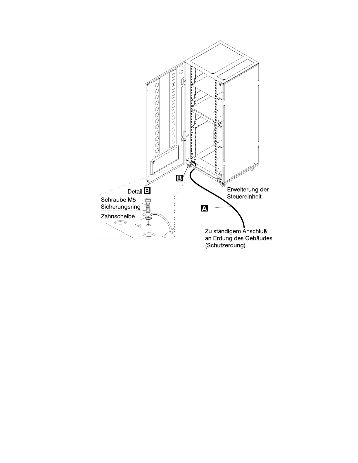
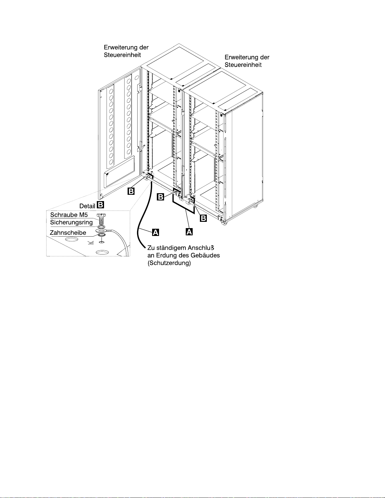
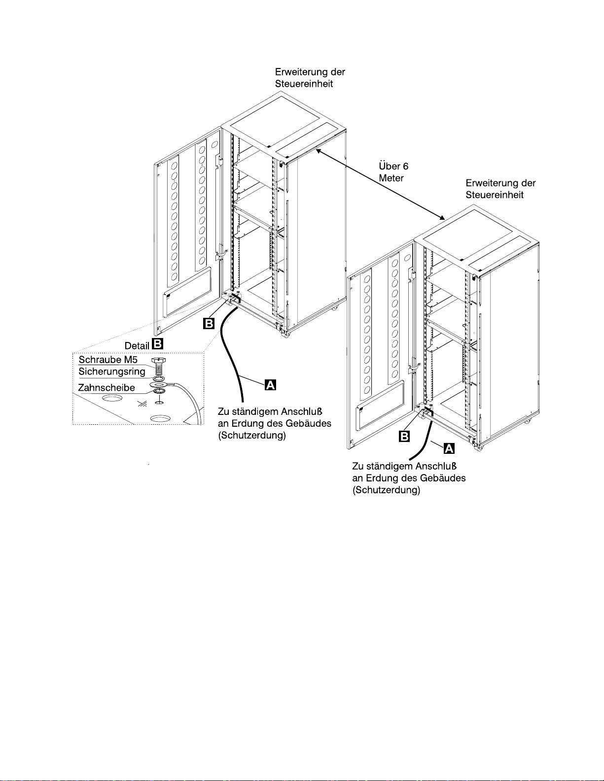
2 Schutzleiter für die Erweiterung der Steuereinheit
Wenn nur eine Erweiterung der Steuereinheit installiert ist, prüfen, ob der
Schutzleiter .A/ angeschlossen ist (siehe Figure 0-12 on page xxxiv).
Wenn mehrere Erweiterungen der Steuereinheit installiert sind, prüfen, ob die
Schutzleiter .A/ gemäß Konfiguration angebracht wurden (siehe Figure 0-13 on
page xxxv, Figure 0-14 on page xxxvi bzw. Figure 0-15 on page xxxvii).
C
3746
Safety xxxiii
Page 36
Safety
Figure 0-12. Schutzleiteranschluß an der Erweiterung der Steuereinheit
xxxiv 3745 Models 130 to 17A: MIP
Page 37
Safety
Figure 0-13. Schutzleiteranschluß zwischen angeschlossenen Erweiterungen der Steuereinheit.
Safety xxxv
Page 38

Safety
Figure 0-14. Schutzleiteranschluß bei einem Abstand von weniger als 6 Meter zwischen den Erweiterungen der
Steuereinheit
xxxvi 3745 Models 130 to 17A: MIP
Page 39
Safety
Figure 0-15. Schutzleiteranschluß bei einem Abstand über 6 Meter zwischen den Erweiterungen der Steuereinheit
Anmerkungen:
a) .A/ Schutzleiter (Teilenummer 58G5691)
b) .B/ Schraube (Teilenummer 61F4513), Zahnscheibe (Teilenummer 1622347) oder
(Teilenummer 17G5853) und Sicherungsring (Teilenummer 1622319).
3 Schutzleiter des AC/DC Stromversorgungskabels
Hauptstromversorgungskabel auf beschädigte oder verbrannte Kontakte und
beschädigte Isolierung prüfen.
Den Widerstand des nicht angeschlossenen Hauptstromversorgungskabels zwischen
dem Schutzleiterkontakt am einen und dem Schutzleiterkontakt am anderen Ende
messen.
Der Widerstand darf maximal 0,1 Ohm betragen.
Safety xxxvii
Page 40
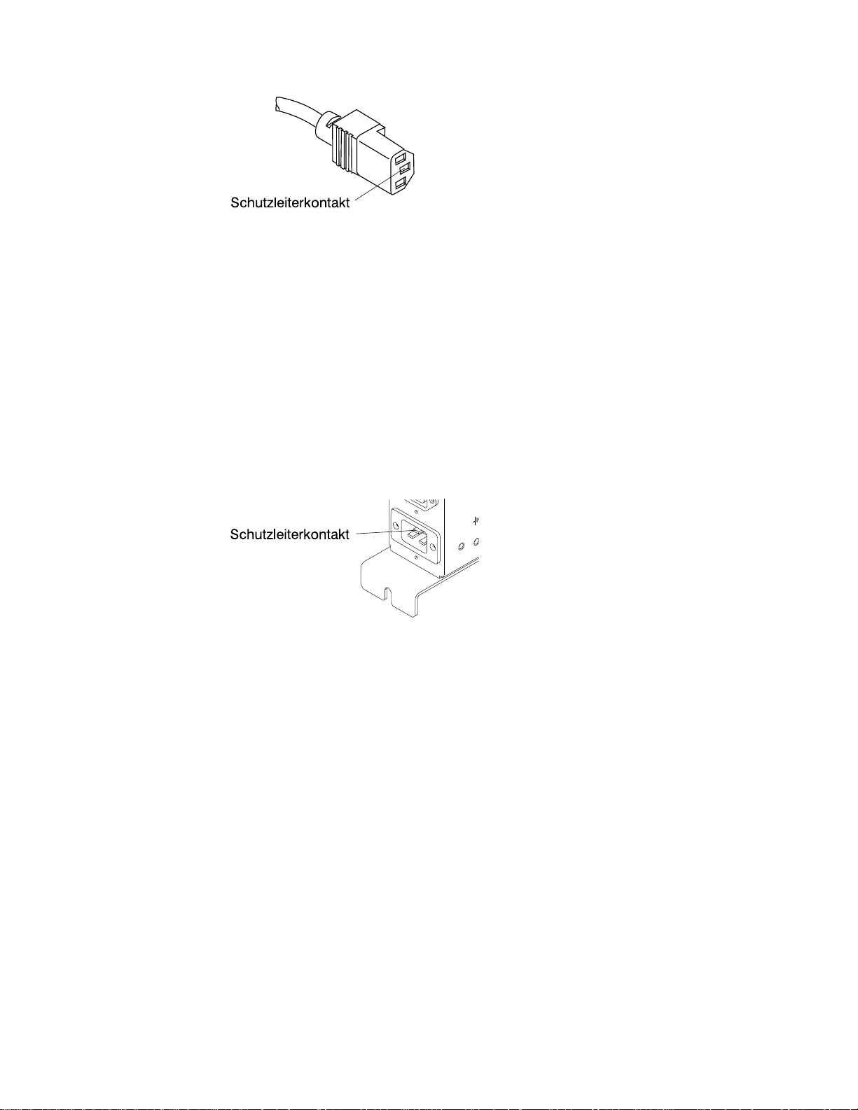
Figure 0-16. Schutzleiterkontakt am Hauptstromversorgungskabel
c Interne Erdung in der 3746-900 und der Erweiterung der Steuereinheit
An der 3746-900
Prüfen, ob der elektrische Durchgang zwischen dem Gehäuse des Verteilerkastens und
dem Rahmen der 3746-900 gewährleistet ist, sofern Verteilerkästen vorhanden sind.
Dieser Schritt muß vor dem Anschluß von Signalkabeln erfolgen.
An der Erweiterung der Steuereinheit
Prüfen, ob der elektrische Durchgang zwischen allen in der Erweiterung der Steuereinheit
installierten Einheiten (Serviceprozessor, Netzknotenprozessor, Modem, optisches
Plattenlaufwerk usw.) und dem Schutzleiterkontakt des Wechselstromverteilerkastens
gewährleistet ist (siehe Figure 0-17).
Prüfen, ob der elektrische Durchgang zwischen dem Schutzleiterkontakt des
Wechselstromverteilerkastens und dem Montagerahmen der Erweiterung der Steuereinheit
gewährleistet ist.
Safety
Figure 0-17. Schutzleiterkontakt des Wechselstromverteilerkastens der Erweiterung der
Steuereinheit
Prüfen, ob der elektrische Durchgang zwischen dem Gehäuse des Verteilerkastens und
dem Rahmen der Erweiterung der Steuereinheit gewährleistet ist, sofern Verteilerkästen
vorhanden sind. Dieser Schritt muß vor dem Anschluß von Signalkabeln erfolgen (siehe
Figure 0-18 on page xxxix).
Anmerkung: Bei allen vorherigen Prüfungen sollten maximal 0,1 Ohm gemessen werden.
d Erdung der nicht in der 3746-900 oder in der Erweiterung der Steuereinheit installierten
Verteilerkästen
Prüfen, ob der elektrische Durchgang zwischen dem Gehäuse des Verteilerkastens und dem
Erdungssystem des Gebäudes gewährleistet ist.
Je nach Installationsort kann der Verteilerkasten auf zweierlei Arten geerdet werden:
1) Erdung über die vier Schrauben, mit denen der Verteilerkasten am Gehäuse befestigt ist,
falls der Gehäuserahmen mit dem Erdungssystem des Gebäudes verbunden ist.
xxxviii 3745 Models 130 to 17A: MIP
Page 41
Safety
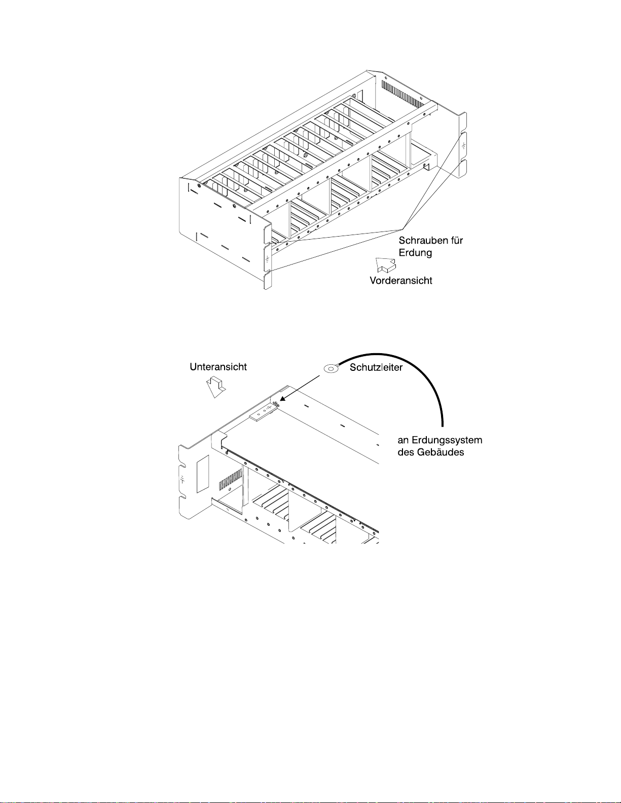
Figure 0-18. Erdung des Verteilerkastens über Schrauben
2) Erdung über einen Schutzleiter, der den Verteilerkasten mit dem Erdungssystem des
Gebäudes verbindet.
Figure 0-19. Erdung des Verteilerkastens über Schutzleiter
IBM liefert diesen Schutzleiter nicht mit. Der Schutzleiter muß aus einem
AWG12-Leiter (mind. 2,5 mm2) bestehen, damit eine korrekte Erdung gewährleistet ist.
Schraube: Durchmesser 5 mm, Länge 6 bis 10 mm (siehe Figure 0-20 on page xl).
Verbindung des Schutzleiters mit dem Verteilerkasten
Safety xxxix
Page 42

Figure 0-20. Schutzleiteranschluß
Dieser Schritt muß vor dem Anschluß von Signalkabeln erfolgen.
Anmerkung: Bei allen vorherigen Prüfungen sollten maximal 0,1 Ohm gemessen werden.
eGebäudeerdung
Sicherstellen, daß zwischen den Metallgehäusen von Steckern, Buchsen usw. und
jeder geerdeten Stelle im Gebäude eine Wechselspannung von weniger als 1 V
anliegt. Dies kann jedes geerdete Metallteil sein, wie z.B. die Stützen eines
Doppelbodens (wenn sie mit dem Gebäudeerder verbunden sind), ein metallisches
Wasserrohr, Baustahl usw..
Anmerkungen:
1) Beim Prüfen an einem lackierten Metallteil sicherstellen, daß die Prüfspitze die Farbe
durchbohrt.
2) Stecker der anzuschließenden Kabel ebenfalls prüfen.
Safety
5 Sicherungsautomat und Überstromschutzschalter
Positionen der Sicherungsautomaten (CB) und Überstromschutzschalter (CP) siehe Table 0-8 on
page xliii.
Prüfen, ob
alle Sicherungsautomaten und Überstromschutzschalter in der 3745 und 3746-900 die unter
Table 0-8 on page xliii angegebene Leistung haben. Wenn die Leistung nicht aufgeführt ist, die
Teilenummer in einem der folgenden Kataloge prüfen:
–
IBM 3745 Communication Controller Models 130 to 17A, Parts Catalog
–
IBM 3746 Expansion Unit Model 900, Parts Catalog
–
IBM 3746 Nways Multiprotocol Controller Models 900 and 950, Parts Catalog
Bei den Sicherungen im Wechselstromverteilerkasten der Erweiterung der Steuereinheit muß es
sich um träge Sicherungen mit 7 A, 250 V handeln (Teilenummer 58G5782).
, S135-2013
, S135-2012
, S135-2015.
6Eingangsspannung
Der zulässige Spannungsbereich (200/220/240V) und die Frequenz (50/60 Hz) sind dem
Typenschild zu entnehmen.
Eingangsspannung an der 3745
Der Aufkleber für die Versorgungsspannungen (Aufkleber J) gibt die Eingangsspannung für die 3745
an. Die Angaben müssen Schalter 1 an PS2 entsprechen.
Stromumwandlung prüfen
Die Stromumwandlung muß bei jeder DFV-Steuereinheit IBM 3745 geprüft werden, die von 50
Hz auf 60 Hz oder von 60 Hz auf 50 Hz umgerichtet wurde.
Folgendes bezieht sich ausschließlich auf das Netzspannungsgehäuse. Die Position kann
Figure 4-1 on page 4-3 entnommen werden.
Die entsprechenden Teilenummern für die Verwendung bei 50 oder 60 Hz sind Table 0-5 on
page xli zu entnehmen. Bei Unstimmigkeiten das KD-Unterstützungspersonal benachrichtigen.
xl 3745 Models 130 to 17A: MIP
Page 43

Safety
Table 0-5. Teilenummern
Frequenzen Teilenummern
50 Hz 03F4745
60 Hz 03F4569
Die Positionen des Auflebers für die Versorungsspannungen und des Typenschildes sind
Figure 0-21 on page lvii zu entnehmen. Informationen zur Spannung?? im Netzteil PS-2 durch
SW1 siehe Seite YZ060, Blatt 1.
Prüfen, ob
die Angaben auf dem Typenschild und dem Spannungsaufkleber der 3745 mit der an der
Netzstromversorgung des Kunden gemessenen Frequenz und Spannung übereinstimmen.
Wenn dies nicht der Fall ist, zuständige Geschäftsstelle informieren.
Eingangsspannung an der 3746-900
Der zulässige Spannungsbereich (200/220/240V) und die Frequenz (50/60 Hz) sind dem
Typenschild zu entnehmen.
Der Spannungsbereich für die 3746-900 liegt bei 200/220/240V.
Prüfen, ob
die Angaben auf dem Typenschild an der 3746-900 mit der am Netzteil des Kunden
gemessenen Spannung und Frequenz übereinstimmen. Wenn dies nicht der Fall ist, zuständige
Geschäftsstelle informieren. Die Position des Typenschildes ist “3745/3746-900 Safety Label
Identifications” on page lx zu entnehmen.
Spannung am Gleichstromeingang
Am Gleichstromeingang muß die Spannung beim Kunden zwischen -40,0 V und -60,0 V liegen.
Der optionale Gleichstromeingang kann nicht eingestellt werden.
Spannung am Wechselstromeingang
Am Wechselstromeingang muß die Spannung beim Kunden zwischen 180 V und 260 V liegen.
Die Einstellung der Eingangsspannung gemäß der Spannung beim Kunden kann an der
Klemmleiste 1 der Transformatoren an der Rückseite der 3746-900 erfolgen.
Table 0-6. Einstellung der Spannung des Wechselstromeingangs
Gemessene
Spannung
180
bis 210 Volt
210
bis 230 Volt
230
bis 260 Volt
Wichtiger Hinweis
:
Position des
Leiters
Klemmleiste TB 1-2 200/208 Volt
Klemmleiste TB 1-3 220 Volt
Klemmleiste TB 1-4 240 Volt
NennSpannung
Die 3745 kann über Fernsteuerung eingeschaltet werden. Deshalb muß bei Ausführung der folgenden
Verfahren die Stromsteuerfunktion am Bedienungsfeld der 3745 und 3746-900 auf Lokal eingestellt sein.
Eingangsspannung der Erweiterung der Steuereinheit
Der zulässige Spannungsbereich (200/240 V) und die Frequenz (50/60 Hz) sind dem Typenschild zu
entnehmen.
Prüfen, ob die Angaben auf dem Typenschild an der Erweiterung der Steuereinheit mit der an der
Netzstromversorgung des Kunden gemessenen Spannung und Frequenz übereinstimmen. Wenn dies
Safety xli
Page 44

nicht der Fall ist, zuständige Geschäftsstelle informieren. Die Position des Typenschildes ist “Controller
Expansion Label Location” on page lxii zu entnehmen.
7 Prüfung des Notaus-Schalters
a. Den Kunden bitten, das Netzkabel an die Netzstromversorgung anzuschließen.
b. Sicherungsautomat (CB1) einschalten.
c. Die 3745 und 3746-900 einschalten (Stromsteuerfunktion am Bedienungsfeld muß auf Lokal
eingestellt sein).
d. Den NOTSCHALTER ausschalten (O) und prüfen, ob:
1) die 3745 und die 3746-900 ausgeschaltet sind.
Hinweis
In der 3746-900 stehen die primären Versorgungs- (ACDC) oder die Filterbereiche
(DCDC) weiterhin unter Spannung.
Komplettes Abschalten:
1. Die Sicherungsautomaten (CBs) ausschalten.
2. Alle Netzstecker aus den Steckdosen ziehen oder die Netzstromversorgung
abschalten.
2) die Disketten- und Plattenlaufwerke angehalten sind.
3) die Lüfter abgeschaltet sind.
e. Notschalter entriegeln und Steuereinheit einschalten.
Safety
8Betriebsanzeige
Nach Einschalten der Steuereinheit prüfen, ob
a. die Betriebsanzeige am Bedienungsfeld der 3745 leuchtet.
b. die Betriebs-LED und die Bereitschafts-LED (am Bedienungsfeld des 3746-900) gemäß den
Angaben der Tabelle “Bedeutung der LEDs am Bedienungsfeld der 3746-900” leuchten.
Bedeutung der LEDs am Bedienungsfeld der 3746-900
Table 0-7. Bedeutung der LEDs am Bedienungsfeld der 3746-900
LED
Bereitschaft
Blinken AUS Wechselstrom
EIN AUS Bereitschaft Die eingangs vom MOSS-E erkannte 3746-900 wartet auf das
AUS Blinken Einschalten Alle 3746-900-Prozessoren werden hochgefahren (IML).
AUS EIN Betrieb Die 3746-900 ist nun betriebsbereit.
LED
Betrieb
Status
3746-900
EIN
Kommentar
Initialisierung der CBSP-Hardware. Die 3746-900 wartet auf
erste Erkennung durch den MOSS-E beim LAN-Anschluß.
Einschalten (nur das CBSP EEPROM-Programm ist aktiv).
xlii 3745 Models 130 to 17A: MIP
Page 45

Safety
Stromversorgung der 3745/3746-900, Sicherungsautomaten (CB),
Überstromschutzschalter (CP) und Sicherungen (F)
Table 0-8. Stromversorgung der 3745, Sicherungsautomaten (CB), Überstromschutzschalter (CP) und
Sicherungen (F)
Rahmen CB/CP/F Position Nennwerte PS (Stromvers.)
Rahmen 1 CB1 01H-A1 10A ALLE
CP2 01H-A1 1,5 A PS2
CP3 01H-B1 2A Ventilatoren
F1 01H-B1 0,2 A PS2
Rahmen 7:
3746-900
CB1 AC 07K-A1/07J-A1 15 A/220 V Wechselstrom
CB1 DC 07J-A1 50 A Gleichstrom
CP1 07K-A1/07J-A1 5 A Gleichstrom
CP2 07H-A1 12 A Gleichstrom
CP3 07H-A1 12 A Gleichstrom
CP4 07H-A1 12 A Gleichstrom
CP5 07H-A1 12 A Gleichstrom
Sicherungen der Erweiterung der Steuereinheit
Der Wechselstromverteilerkasten der Erweiterung der Steuereinheit enthält zwei Sicherungen: 7 A 250 V
träge.
Safety xliii
Page 46

Safety
xliv 3745 Models 130 to 17A: MIP
Page 47

Safety
Safety xlv
Page 48
Safety
xlvi 3745 Models 130 to 17A: MIP
Page 49
Safety
Safety xlvii
Page 50
Safety
xlviii 3745 Models 130 to 17A: MIP
Page 51
Safety
Safety xlix
Page 52
Safety
l 3745 Models 130 to 17A: MIP
Page 53

Safety
Safety li
Page 54
Safety
lii 3745 Models 130 to 17A: MIP
Page 55
Safety
Safety liii
Page 56
Safety
liv 3745 Models 130 to 17A: MIP
Page 57

Safety
Safety lv
Page 58

Safety
lvi 3745 Models 130 to 17A: MIP
Page 59
Safety
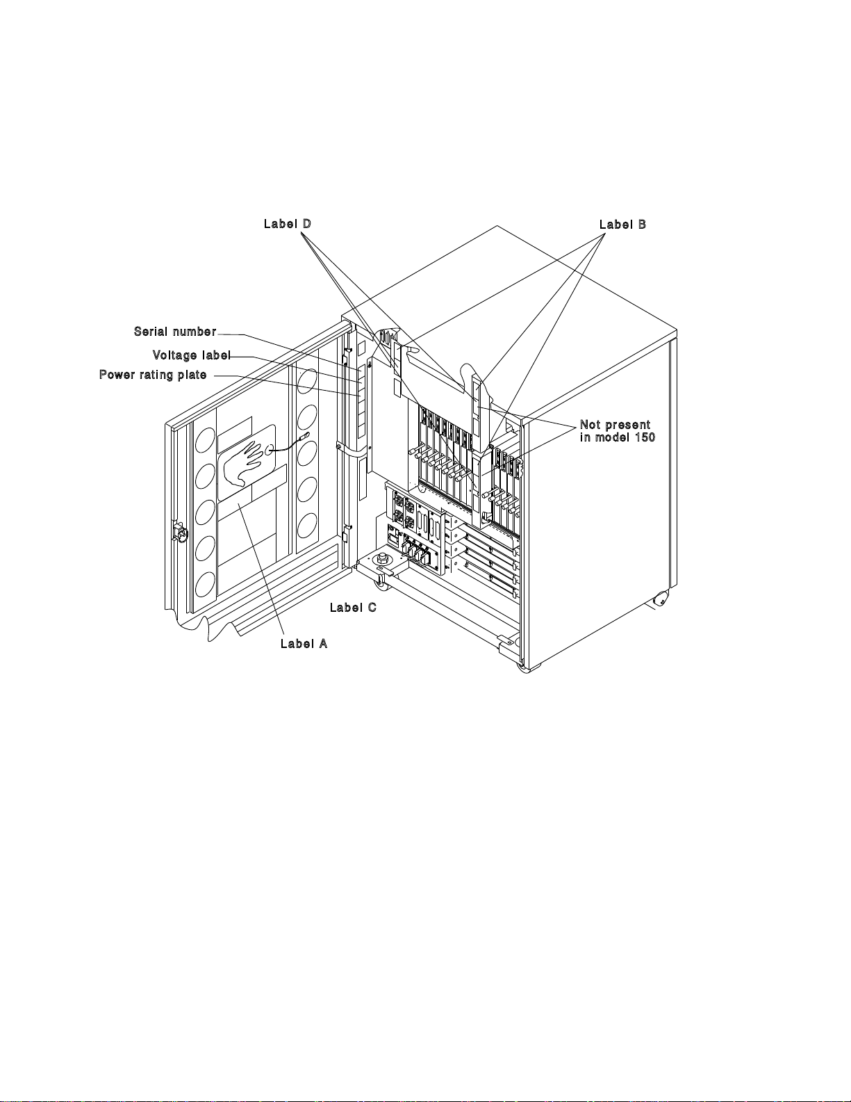
Safety Label Locations
Safety Labels on the 3745
On the following figures, labels are designated by letters. A particular wording corresponds to each letter
(see “3745/3746-900 Safety Label Identifications” on page lx).
Figure 0-21. 3745 Label and Power Rating Plate Locations (Back)
Safety lvii
Page 60

Safety
Figure 0-22. 3745 Label and Power Rating Plate Locations (Front)
lviii 3745 Models 130 to 17A: MIP
Page 61

Safety
Safety Label on the 3746-900
On the following figures, labels are designated by letters. A particular wording corresponds to each letter
(see “3745/3746-900 Safety Label Identifications” on page lx).
Power Rat ing Pl ate
(Under t he cover)
Front View
Figure 0-23. 3746 Model 900 (Frame 07) Label Locations
Safety Label on LCB
S
(Under t he cover)
Rear View
Figure 0-24. LCB Safety Label Location
Safety lix
Page 62

3745/3746-900 Safety Label Identifications
The safety labels shown in Figure 0-25 on page lx and in Figure 0-26 on page lxi are in the English
language. They are also available in other languages. See “Safety Label Part Numbers by Country” on
page lxiii for ordering.
Safety
LABEL A
LABEL C
CAUTION
DUE TOCONNECTED EQUIPMENT
HAZARDOUSVOLTAGES
MAYBEPRESENT AT ANY TIME
LABEL B LABEL D
HAZARDOUSAREA
TRAINED SERVICE
PERSONNEL ONLY
LABEL E
LABEL G
(Same as label B
but in local
language)
LABEL F
LABEL H
(Same as label A
but in local
language)
> 18 Kg
Figure 0-25. 3745/3746-900 Safety Labels
DO NOT OPEN
NE PAS OUVRIR
NICHT ÖFFNEN
NIET OPENEN
NON APRIRE
NO ABRIR
~
NAO ABRIR
lx 3745 Models 130 to 17A: MIP
Page 63

Safety
LABEL K1
HASARDOUS AREA
TRAI NED SERVI CE
PERS ONNEL ONLY
LABEL K2
HASARDOUS AREA
TRAI NED SERVI CE
PERS ONNEL ONLY
LABEL L
LINE VOLTAGE
PRESENT WITH
MACH INE P OWE R O F F
LABEL M
HAZARDOUS E NERGY
IS PRESENT WHERE
THE CASSETE IS
PL UGGE D I N
SWITCH "OFF" CB1
AT 07K-A1 FOR THIS
SI DE T RANSFORME R
BEFORE REMOVING THE COVER
SWICTH "OFF" CB1
AT 07J-A1 FOR THIS
SI DE T RANSFORME R
BEFORE REMOVING THE COVER
LABEL A
CAUT ION
REMOVE PRI MARY
POWER CORD B EFORE
REMOVING COVER
LABEL D
CAUT ION
LABEL N1
LABEL N2
>18Kg
LABEL P
CAUT ION
1 - SWITCH OFF THE DC BOX CB1
2 - SWIT CH OF F T HE CUSTOME R CI RCUI T BREA KER
3 - ATTACH A WARNI NG L ABEL DI RE CTLY TO THE
CIRCUIT BRE AKER INDICATING T HAT
"POWER MUST NOT BE APPLIED"
4 - DI SCONNECT THE SUPP LY CABLE F ROM THE
CUS T OME R J U NCTI ON B OX
5 - L AST, DI SCONNE CT SUP PLY CABLE F ROM THE
DC P OWER BOX
Figure 0-26. 3745/3746-900 Safety Labels
>32Kg
LABEL Q
60 VDC
<
240 VA
>
Safety lxi
Page 64
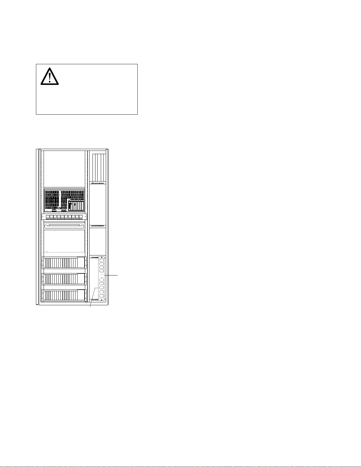
LCB Safety Label
LABEL S
HIGH LEAKAGE CURRENT
Permanent ground connection
is mandatory
before network connections.
Figure 0-27. LCB Safety Label (PN 80G3928)
Controller Expansion Label Location
Safety
8
3
4
6 5
2
7
1
K M
AC Outlet
Distribution Box
Power Rating
Plate
Figure 0-28. Controller Expansion Power Rating Plate Location
lxii 3745 Models 130 to 17A: MIP
Page 65

Safety
Safety Label Part Numbers by Country
The following table gives the label group part number according to the language(s) of the country in which
the 3745 is installed.
Table 0-9. Safety Label Numbers by Country
Language 3745
Frame 1
Part
Number
Canadian French 03F4861 17G5876 80G3928
Danish 03F4869 72F0673 17G5876 80G3928
Dutch 03F4872 72F0676 17G5876 80G3928
English 03F4860 72F0664 17G5876 80G3928
Finnish 03F4870 72F0674 17G5876 80G3928
French 03F4862 72F0665 17G5876 80G3928
French/Dutch 03F4871 17G5876 80G3928
German 03F4863 72F0666 17G5876 80G3928
Italian 03F4864 72F0667 17G5876 80G3928
Japanese 03F4867 72F0670 17G5876 80G3928
Norwegian 03F4868 72F0671 17G5876 80G3928
Portuguese 03F4865 72F0668 17G5876 80G3928
Spanish 03F4866 72F0669 17G5876 80G3928
Swedish 03F4873 72F0677 17G5876 80G3928
3746-900
Part
Number
3746-900
Label Q
LCB
Label S
Safety lxiii
Page 66

Safety
lxiv 3745 Models 130 to 17A: MIP
Page 67

Preface
Preface
About this Manual
This MIP is a guide for fault isolation and repair of the 3745 Communication Controller. It is expected that
the customer has used the .
Analysis Guide
done by the
The MIP gives the service representative information needed to:
Analyze problems or symptoms reported by the system user.
Restore normal 3745 operation.
(online document) prior to calling IBM for service. The MIP does not duplicate the tasks
Problem Determination Guide
Problem Determination Guide
.
, SA33-0096 or the 3745 Models A,
Problem
Who Should Read this Manual
The person using this manual should be:
Trained to service the 3745 and 3746-900.
Familiar with the configuration of the system to which the 3745 is connected.
Familiar with the operation of the 3745, as described in the
Reference
are part of this Maintenance Library.
The intended audience for this manual are Product-Trained Customer Engineers (PT CE). The Product
Support-Trained Customer Engineer (PST CE) is also expected to refer to this manual when he is required
to perform the same tasks as the PT CE.
, SY33-2066 and
IBM 3745 Communication Controller Service Function
IBM 3745 Hardware Maintenance
, SY33-2069, which
How this Manual Is Organized
This manual is organized as follows:
Safety information is at the start of the manual.
From Chapter 1 through Chapter 4, this manual is designed so that the information is presented to
the user in the same order as he will require it during the majority of service calls. The user is told
where to go next for each path through this part of the manual.
At the back of the manual are:
– Appendix A, Maintenance Aids
– Appendix B, Bibliography
– Appendix X: Abbreviation list and glossary.
Copyright IBM Corp. 1989, 1997 lxv
Page 68

Preface
lxvi 3745 Models 130 to 17A: MIP
Page 69

Amendments
Summary of Changes
All MAPs, exchange procedures, and so on, referring to the 3746-900, have been removed in this edition
except for the "Service Inspection Safety Procedures".
For information concerning the 3746 Model 900 refer to the
Model 900 Service Guide
Corrections and improvements relating to the previous edition have also been inserted.
, SY33-2116.
IBM 3746 Nways Multiprotocol Controller
Copyright IBM Corp. 1989, 1997 lxvii
Page 70

Amendments
lxviii 3745 Models 130 to 17A: MIP
Page 71

START
Chapter 1. START: How to Begin Troubleshooting
Important
Your personal safety can never be over-emphasized.
You have been taught safety procedures since the earliest phase of your IBM training.
Your safety is part of every maintenance call.
You are the only one who can make a maintenance call safe.
Specific information can be found in “Product Safety Information” on page xvii and “Safety Label
Locations” on page lvii.
Start here when you use this manual to repair a 3745/3746 hardware failure.
Remember that the 3745/3746 are machines which are designed to be repaired while the cus-
tomer is still using the operational areas. This is called Concurrent Maintenance. Before
changing FRUs, you will be directed to ensure that you have the correct area of the machine
ready for maintenance.
When a power supply is shared between adapters, the disabling procedures apply to both 'sus-
pected' and 'associated' adapters.
During a call for service, it will normally be necessary to use the 3745 console. To log ON at a
3745 console, proceed as directed in “Console Use for Maintenance.”
Console Use for Maintenance
001
Is the 3745 a Model 17A?
Yes No
002
The 3745 is a Model 130, 150, 160, or 170.
The 3745 has password protection for functions controlled via a console. Several types of password
exist for different activities. They are described in the
SA33-0097.
Obtain the maintenance password from the customer so that you can log on at the 3745 console
(local, remote, or alternate). This password will give you access to Menu 3 Maintenance Func-
tions, in addition to Menu 1 and Menu 2.
If the 3745 failure prevents correct operation of the 3745 console, continue at “Selection Table” on
page 1-4 .
Log ON at the 3745 console as follows:
1. Ensure that the customer is not using the console and that he has logged OFF. The channel
enable/disable screen is displayed.
2. Press F4: MOSS FUNCTIONS.
3. The password screen is displayed.
4. Enter the maintenance password.
Note: Remember to log OFF the console and to re-IML the MOSS at the end of the service call.
See “CE Leaving Procedure” on page 4-102 for more information.
Continue with “Selection Table” on page 1-4.
IBM 3745 Advanced Operation Guide
,
003
The 3745 is a Model 17A.
(Step 003 continues)
Copyright IBM Corp. 1989, 1997 1-1
Page 72

003 (continued)
Is the service processor operational?
Yes No
004
Continue with “Selection Table” on page 1-4.
005
Obtain the service processor maintenance password from the customer so that you can log ON at the
service processor console.
To log ON:
1. On the MOSS-E View window, click on Program (in the action bar).
2. Click on Log On MOSS-E.
3. Enter the password.
Are you here to investigate a RSF problem?
If you do not know, continue with Step 006.
Yes No
006
1. On the MOSS-E View window, double-click on the service processor icon.
2. The Service Processor Menu window is displayed.
3. Click on the Configuration Management option.
4. Double-click on the Manage Remote Operations option.
5. On the Remote Operation Management window, select the Remote operations authorization
option and click on OK.
6. On the Remote Support Facility window, select the following two options:
Disable Remote Support Facility
Do not generate alerts
7. Click on OK.
8. Continue with Step 007.
START
007
Continue with “Selection Table” on page 1-4 .
See “Service Processor Window Overview” on page 1-3 for the main panels used to perform the procedures documented in this manual.
1-2 3745 Models 130 to 17A: MIP
Page 73

START
Service Processor Window Overview
MOSS-E View
Controller
3745 3746
3745 Menu
Service Processor
Service Processor Menu
Function Options Help
Configuration Management
Problem Management
Operation Management
Change Management
Manage Ethernet Bridge
Configuration Management
Communications Manager/2
FFST/2
LAPS
Manage Remote Operation
Set Time and Date
Customize DCAF Target Settings
Manage 3745/3746-9x0 Installation/Removal
Start/Configure TCP/IP
Function Options Help
MOSS Console
Problem Management
Operation Management
3746-9x0 Menu
Function Options Help
Configuration Management
Problem Management
Network Node Processor (NNP) Management
Multiaccess Enclosure (MAE) Management
Operations Mangement
Change Management
Performance Management
Functions to Use Under PE Guidance
(For a detailed menu, see the 3746-900
Service Guide)
Problem Management
Display Alarms
Manage Alarms/Errors/Events (SRCs)
Report Problem Using Remote Support Facility
Operation Management
Set 3745/MOSS-E Connection Mode
Locate Bypass Card Position
Problem Management
Display Alarms
Manage Alarms/Errors/Events (SRCs)
Transfer NCP Dump
Connect/Disconnect 3746-9x0 from MOSS-E
Operation Management
Manage Disk and Data Base
Manage Passwords
Display Files
Retrieve Engineering Data
Delete Engineering Data
Capture and Save Screens
Change Management
Manage Microcode Changes
Change Active Code
Manage Microcode Fixes
Set Automatic Microcode Download Option
Manage Ethernet Bridge
Configure Ethernet Bridge
Configure SNMP
Chapter 1. START: How to Begin Troubleshooting 1-3
Page 74

Selection Table
Going from top to bottom in the table, select the first entry point which fits your situation.
If You Have a: Then Go to:
General Verbal Symptoms The “General Verbal Symptoms” on page 1-8.
Color symptom for 3745/3746-900 icons
on MOSS-E View window.
Customer problem number (CPN) The “3745 and Service Processor Maintenance Using a
Maintenance actions The “3745 Maintenance Actions” on page 1-6.
Problem during installation The “Problems During Machine, EC, or MES Installation”
Problem while installing an EC or MES The “Problems During Machine, EC, or MES Installation”
3745/3746-900 power symptoms The “3745 Power Symptoms” on page 1-12.
3745 reference code “Using Reference Codes” on page 1-14.
3745 FRU group number to exchange “Using the MIP FRU Group Table” on page 1-48.
3745 FRU list to exchange The “3745 FRU List” on page 1-53.
3745 control panel code reported The “3745 Control Panel Codes” on page 1-15.
3745 control panel symptoms The “3745 Control Panel Symptoms” on page 1-11.
3745 service processor link symptom “MAP 5600: LAN Problem on the LAN Attached to the
3745 IOC bus symptoms “MAP 0100: IOC Bus Trouble Shooting” on page 2-1.
3745 console symptoms The “3745 Console Symptoms” on page 1-10.
3745 'Disk not ready' message on the 3745
console
or 'Disk error' message
or 'Diskette error' message
3745 console message displayed Most messages are self explanatory. If necessary, go to
Alarm reported on the 3745 Model 17A The
3745-XXA apply a microcode fix The
3745-XXA RSF link down “MAP 4510: 3745 Model 17A Manual Call” on page 2-33
Service processor symptom The "Service Processor Problem Determination" in the cor-
Network node processor symptom The "Network Node Processor Problem Determination" in
Service processor system reference code
sequence number
Service processor apply a microcode change "Handling the Microcode Change Level" in the chapter
Problem with the service processor integrated
modem
Problem on the external modem attached at the
service processor
“MAP 5200: 3745/3746-900/Service Processor/Network
Node Processor Icon Color Symptoms” on page 2-37
CPN” on page 1-55
on page 1-7.
on page 1-7.
Service Processor” on page 2-42
“How to Perform 3745 Control Panel Operations” on
page 1-82. Perform a MOSS IML, and restart, using the
control panel code reported.
the
3745 Problem Determination Guide, 3745 Service
Functions
or “3745 Advanced Operations Guide”.
Problem Analysis Guide
(online book)
Service Processor Installation and Maintenance
manual. Use the "Handling the Microcode Change Levels"
procedure in the chapter "Maintaining the Code Loaded on
the Service Processor".
responding
manual.
the corresponding
Maintenance
The “Service Processor Maintenance Using an SRC
Sequence Number” on page 1-57.
"Maintaining the Code Loaded on the Service Processor" in
the corresponding
Maintenance
"How to Run the Service Processor Diagnostics" in the corresponding
manual, and run the integrated V.32 modem test, or refer
to the
tion, Operation, and Problem Determination Guide
Refer to the modem documentation.
For IBM the 7855 modem refer to the problem determi-
nation chapter in the
Operation
For IBM the 7857 modem refer to the problem determi-
nation chapter in the
ation
For the Hayes** modem, refer to the corresponding
manual.
Service Processor Installation and Maintenance
Network Node Processor Installation and
manual.
Service Processor Installation and
manual.
Service Processor Installation and Maintenance
IBM Asynchronous/SDLC V.32 Modem/A; Installa-
.
7855 Modem Model 10, Guide to
.
IBM 7857 Modem Guide to Oper-
.
START
1-4 3745 Models 130 to 17A: MIP
Page 75

START
If You Have a: Then Go to:
Problem on the 3746-900, or attached features The
IBM 3746 Nways Multiprotocol Controller Model 900
Service Guide
, SY33-2116.
Chapter 1. START: How to Begin Troubleshooting 1-5
Page 76

3745 Maintenance Actions
If You Want to: Then Go to:
Run 3745 diagnostics in offline mode (ODG) The “3745 Diagnostic Requirement” on page 1-60.
Run 3745 diagnostics in concurrent maintenance
mode (CDG)
Run the 3745/3746-900 LIC wrap test (WTT) “How to Run the Wrap Test (WTT) for TSS, HPTSS, or
Find information about using the 3745 control
panel
Know the definition of a 3745 control panel code The “3745 Control Panel Codes” on page 1-15.
Install a 3745 The
Find information about using the 3745 MOSS
console
Find information about connected consoles The
Find the level of a FRU installed. The
Check voltages on 3745 The 3745 YZ pages
Change parameters for the 3745 LIC type 5 or 6. Appendix B, “PKD (Portable Keypad Display) Maintenance
Apply a Microcode Fix on the 3745-17A "Handling the Microcode Change Level" in the chapter
Find information about using the service
processor console
Test the 3745-17A RSF link “MAP 4510: 3745 Model 17A Manual Call” on page 2-33.
Find information about customer console on
3745-17A
Perform Engineering Data Transfer The “Engineering Data Transfer” on page 1-58.
Run diagnostics on the service processor "How to Run the Service Processor Diagnostics" in the cor-
Run diagnostics on the network node processor The "Network Node Processor Problem Determination" in
Apply a microcode change on a service processor "Handling the Microcode Change Level" in the chapter
Find the modem setting for RSF The
Run diagnostics on the 3746-900 or attached features
Find miscellaneous information “Miscellaneous Information” on page 1-13.
The “3745 Diagnostic Requirement” on page 1-60.
3746-900” on page 3-15.
“3745 Control Panel Use” on page 1-78.
3745/3746-900 Installation Guide
The
3745 Service Functions Guide
3745 Console Setup Guide
3745 Service Functions Guide
Aids for LIC 5 and 6” on page A-5.
"Maintaining the Code Loaded on the Service Processor" in
the corresponding
Maintenance
The
3745 Models A, Basic Operations Guide
The
3745 Console Setup Guide
responding
manual.
the corresponding
Maintenance
"Maintaining the Code Loaded on the Service Processor" in
the corresponding
Maintenance
Service Processor Installation and
manual.
Service Processor Installation and Maintenance
Network Node Processor Installation and
manual.
Service Processor Installation and
manual.
, SY33-2067
, SY33-2069.
, SA33-0158.
, SY33-2069.
, SA33-0177.
, SA33-0158.
Service Processor Installation and Maintenance
manual. Use the "Installing and Connecting the RSF
Modem to the Service Processor" procedure according to
your modem type.
The
IBM 3746 Nways Multiprotocol Controller Model 900
Service Guide
, SY33-2116.
START
1-6 3745 Models 130 to 17A: MIP
Page 77

START
Problems During Machine, EC, or MES Installation
When installing a 3745, the
an MES, the supplied instructions should be used. It is possible that the task or diagnostic you were
asked to perform during the installation detected an error, and you were requested to start troubleshooting
using this manual.
The primary purpose of this manual is to resolve problems that occur in an operational environment after a
successful installation. That is, the machine has worked previously and is now failing.
At installation time, or after an EC or MES is installed, it is possible that errors may occur due to conditions which would not exist in an operational environment.
Cables plugged incorrectly
Terminators missing
Mismatch between CDF and machine configuration
Mismatch between line characteristics and setups
Wrong address set
Top card connectors incorrectly installed
Loose cards.
During your path through the MIP, you should remember these possibilities and, when the failing area is
identified, check with the aid of the
that these conditions do not exist prior to changing FRUs.
3745 Installation Guide
3745 Hardware Maintenance Reference
, SY33-2067 should be used. When installing an EC or
, SY33-2066 and YZ pages
Now, starting at the top of the “Selection Table,” work down until you find an entry that matches the
symptom detected during the installation.
Be sure to read “Exchange Precautions” on page 4-1 before removing any FRUs from this
machine.
Selection Table
If You Have a: Then Go to:
Reference code (see the "3745 Problem
Determination/Analysis Guide", Alarms)
3745 control panel code reported “3745 Control Panel Codes” on page 1-15.
3745 Power Symptoms “3745 Power Symptoms” on page 1-12.
IOC bus symptoms “MAP 0100: IOC Bus Trouble Shooting” on page 2-1.
3745 console symptom “3745 Console Symptoms” on page 1-10.
3745 control panel symptom “3745 Control Panel Symptoms” on page 1-11.
General verbal symptom “General Verbal Symptoms” on page 1-8.
Error detected by diagnostics on the 3745 “Diagnostic and Exchange Result Analysis 0000” on
3745 console message displayed Most messages are self explanatory. If needed go to the
CDF undefined error Correct the CDF using the manual update function (option
“Using Reference Codes” on page 1-14.
page 4-99.
"3745 Problem Determination Guide", "3745 Service Func-
tions", or "Advanced Operation Guide".
S). Refer to the
Service Function
IBM 3745 Communication Controller
, SY33-2069.
Chapter 1. START: How to Begin Troubleshooting 1-7
Page 78

Symptom Index
General Verbal Symptoms
Table 1-1 (Page 1 of 2). General Symptoms
If the: Symptom: Then:
Has detected
Channel errors on this
3745
Host
3745 using a channel
3745 using the MOSS HDD
Route inop
Missing interrupt
Has detected channel
errors on the 3746-900
Is unable to load/dump the
control program via the
3745 CA
Is unable to load/dump the
control program via the
3746-900 ESCA
Is unable to activate an
ESCA or there is no traffic
on the ESCA
Is unable to load/dump the
control program
Go to “MAP 3500: Activate/Deactivate Line
Problem or Line Errors on the TSS” on
page 2-7.
Refer to the
troller Model 900 Service Guide
Go to “MAP 3500: Activate/Deactivate Line
Problem or Line Errors on the TSS” on
page 2-7.
Refer to the
troller Model 900 Service Guide
Refer to the
troller Model 900 Service Guide
Refer to “How to Run MOSS Diagnostics” on
page 3-4 and continue with the error
detected.
If no error is detected, go to the "Service
Function Guide" for HDD problems.
IBM 3746 Nways Multiprotocol Con-
, SY33-2116.
IBM 3746 Nways Multiprotocol Con-
, SY33-2116.
IBM 3746 Nways Multiprotocol Con-
, SY33-2116.
Symptom Index
1-8 3745 Models 130 to 17A: MIP
Page 79
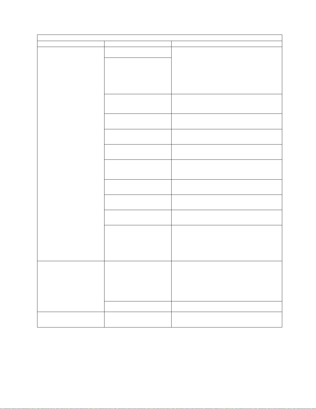
Symptom Index
Table 1-1 (Page 2 of 2). General Symptoms
If the: Symptom: Then:
3745
Hardware central service
Service processor
Is unable to activate (start)
a line or a ring
Has errors while running
lines or rings
Is unable to activate (start)
a ring or has errors while
running a ring connected to
a 3746-900
Is unable to activate (start)
or has a problem on all the
lines of a 3746-900 CLP.
Is unable to activate (start)
or has a problem on all the
lines of a 3746-900 LIC11.
Is unable to activate or has
a problem on all the lines of
the same ARC group
Is unable to activate or has
a problem on all the lines of
the same line connection
box expansion (LCBE)
Is unable to activate or has
a problem on all the lines of
a 3746-900 LIC12
Is unable to activate or has
a problem on all the lines of
a 3746-900 LIC16
Has a suspected program
loop or hang
Has unexpected re-IPLs
Is unable to activate an
RSF link
The 3745 Model 17A, has
the RSF link down
Is unable to establish a link
with a 3745 or 3746-900
1. For TSS: go to “MAP 3500:
Activate/Deactivate Line Problem or Line
Errors on the TSS” on page 2-7.
2. For TRSS : go to “MAP 3520:
Activate/Deactivate Ring Problems or Ring
Errors on the TRSS” on page 2-8.
3. For HPTSS or ESS : go to “MAP 3530:
Activate/Deactivate Line Problems or Line
Errors on the HPTSS/ESS” on page 2-9.
Refer to the
troller Model 900 Service Guide
Refer to the
troller Model 900 Service Guide
Refer to the
troller Model 900 Service Guide
Refer to the
troller Model 900 Service Guide
Refer to the
troller Model 900 Service Guide
Refer to the
troller Model 900 Service Guide
Refer to the
troller Model 900 Service Guide
Call your support structure for assistance with
this problem. Refer to “Contacting Support” on
page A-1.
If a message with a reference code is gener-
ated, go to “Using Reference Codes” on
page 1-14.
If no message with a reference code is gen-
erated at the re-IPL, contact your support
structure for assistance. Refer to “Contacting Support” on page A-1.
Run the RSF console link test, refer to “How
to Run the Console Link Test for 3745
Models 130, 150, 160, and 170” on
page 3-6.
If no error is detected suspect the modem or
line. Ask the customer to perform problem
determination or call the appropriate service
representative.
Go to “MAP 4510: 3745 Model 17A Manual
Call” on page 2-33.
Go to “MAP 5600: LAN Problem on the LAN
Attached to the Service Processor” on
page 2-42.
IBM 3746 Nways Multiprotocol Con-
, SY33-2116.
IBM 3746 Nways Multiprotocol Con-
, SY33-2116.
IBM 3746 Nways Multiprotocol Con-
, SY33-2116.
IBM 3746 Nways Multiprotocol Con-
, SY33-2116.
IBM 3746 Nways Multiprotocol Con-
, SY33-2116.
IBM 3746 Nways Multiprotocol Con-
, SY33-2116.
IBM 3746 Nways Multiprotocol Con-
, SY33-2116.
Chapter 1. START: How to Begin Troubleshooting 1-9
Page 80

3745 Console Symptoms
Table 1-2. 3745 Console Symptoms
If a: Then:
Local/Remote/RSF or alternate console appears
not to function or functions incorrectly
"Disk not ready" message
or
"Disk error" message
or
"Diskette error" message
3745 console message is displayed
On 3745 Models 17A, the RSF link is down
Service processor is failing
or
Service processor symptom appears
Ensure that the Problem Determination Guide
has been followed.
Perform a MOSS IML. See “How to Perform
3745 Control Panel Operations” on page 1-82.
Restart using the reported Control Panel code.
Most messages are self explanatory.
If necessary, refer to the:
Problem Determination Guide
IBM 3745 Communication Controller Service
Function
IBM 3745 Advanced Operation Guide
SA33-0097.
Go to “MAP 4510: 3745 Model 17A Manual
Call” on page 2-33.
Refer to the "Service Processor Problem Determination" in the corresponding
Processor Installation and Maintenance
, SY33-2069
, SA33-0096
,
Service
manual.
Symptom Index
1-10 3745 Models 130 to 17A: MIP
Page 81

Symptom Index
3745 Control Panel Symptoms
Table 1-3. Control Panel Symptoms
If the 3745 Then:
Run the Control Panel test. Refer to “How to Run
the Control Panel Test” on page 3-8.
Control panel displays any wrong character or all
segments of all characters are ON
Control panel display has a missing character
Has one or more control panel keys that do not
work
MOSS message indicator is always ON without
a console pending message
MOSS inoperative indicator is always ON even if
MOSS is operating
Control panel display is blank
"All Channel Adapters Disabled" indicator is in
an invalid state
"Console in Use" indicator shows the wrong
console
Power On Indicator is not ON
When a FRU group is called for an error, go to
“3745 FRU Group Table” on page 1-49.
If no error is detected and the problem still exists,
call your support structure for a possible microcode
problem. Refer to “Contacting Support” on
page A-1.
Run the Control Panel test. Refer to “How to Run
the Control Panel Test” on page 3-8.
When a FRU group is called for an error, go to
“3745 FRU Group Table” on page 1-49.
If no error is detected, go to “How to Run MOSS
Diagnostics” on page 3-4.
Go to “Power MAP 3930: Power Control Subsystem
Problems” on page 2-21.
Run the Control Panel test. Refer to “How to Run
the Control Panel Test” on page 3-8.
When a FRU group is called for an error, go to
“3745 FRU Group Table” on page 1-49.
If no error is detected, go to “How to Run MOSS
Diagnostics” on page 3-4.
Refer to “How to Run MOSS Diagnostics” on
page 3-4 and continue with the error detected.
If no error is detected, exchange the FRU group 52.
Go to page 1-49.
Go to “Power MAP 3930: Power Control Subsystem
Problems” on page 2-21.
Chapter 1. START: How to Begin Troubleshooting 1-11
Page 82

3745 Power Symptoms
Table 1-4. Power Symptoms
If the: Symptom: Then:
Will not power ON
Will not perform a scheduled
power ON
Host power ON sequence stops at
the 3745
Power On Indicator is not ON
3745
Control panel display is blank
Will not power OFF
Will not power OFF when a power
OFF command is sent by the
control program
Symptom Index
Go to “Power MAP 3930: Power Control Subsystem
Problems” on page 2-21.
Go to “Power MAP 3925: Scheduled Power on Problems”
on page 2-20.
Go to “MAP 3905: Power ON Problem in Host Mode or
Host Power Sequence Problem” on page 2-16.
Go to “Power MAP 3930: Power Control Subsystem
Problems” on page 2-21.
Go to “Power MAP 3935: Power OFF not Possible in Host
Mode” on page 2-25.
or
Go to “Power MAP 3945: Power OFF not Possible in
Local Mode” on page 2-26.
Go to “Power MAP 3960: Power OFF not Possible in
Network Mode” on page 2-28.
1-12 3745 Models 130 to 17A: MIP
Page 83

Symptom Index
Miscellaneous Information
If You Want to: Then Go to:
Find information about the 3745 console
Maintenance
Setup
Customer MOSS functions
Find the level of an installed FRU
Check voltages YZ pages, and
Find information about the maintenance aids for:
Control program
Microcode
Special tools
PKD and LIC5/6
IBM 3745 Communication Controller Service
Function
IBM 3745 Console Setup Guide
IBM 3745 Advanced Operation Guide
, SY33-2069
, SA33-0158
, SA33-0097
IBM 3745 Communication Controller Service Function
SY33-2069 CDF chapter.
IBM 3745 Hardware Maintenance
Reference
See this manual appendix A
(specifications chapter).
,
Chapter 1. START: How to Begin Troubleshooting 1-13
Page 84

Reference Codes
Using Reference Codes
Reference Codes (8 digits) are always displayed at the rightmost position of the alarm on the 3745
console. They are generated by the microcode which runs within the MOSS to provide an automatic
analysis of box event records (BERs). This function is known as auto-BER and is part of the AUTOMAINT
facility. Reference codes are also generated when diagnostics detect an error.
If several alarms have been generated for the same problem, resulting in multiple reference codes, use
the reference code beginning with BX, if any. If there are no BX codes, use the reference code given by
the earliest alarm.
To analyze a reference code to find the correct action to take, use the following procedure on the 3745
console:
1. From the Maintenance Functions on Menu 3, select the BRC function.
The reference code screen will be displayed (see Figure 1-1).
à
@
CUSTOMER ID: 3745 SERIAL NUMBER:
CCU-A SELECTED PROCESS MOSS-OFFLINE X71:2415
X72:85
RUN-REQ
-------------------------------------------------------------- 3/1/89 1:22
FUNCTION ON SCREEN: BER CORRELATION
ENTER REFERENCE CODE ==>
===>
F1:END F2:MENU2 F3:ALARM F5:BER CORRELATION F6:ADDITIONAL INFO
á
Figure 1-1. Reference Code Screen
REFERENCE CODE INTERPRETATION
ð
ñ
2. Type in the 8-digit reference code you want to analyze in the input area of the screen. Refer to
Figure 1-1.
3. Press SEND the action you are required to perform will appear on the screen.
Note
When the microcode is a possible cause of the error, it is recommended that you check:
1. If you have the highest level of microcode for your machine.
2. That any applicable MCFs are installed.
Your support structure will have this information.
4. Hit F6 for additional information (on associated components and customer resources for TSS,
HPTSS and ESS), and record the data for later usage.
Note: If the CDF is not correct, this information can be wrong.
5. When the FRU list is given, record the types and location, then use the “3745 FRU List” on
page 1-53.
If the reference code is reported as 'INVALID' or 'DUMMY', check that you have entered the same code as
reported. If so, an error in the BER analysis or BER logging has occurred. Contact your support structure
for assistance. See “Contacting Support” on page A-1.
1-14 3745 Models 130 to 17A: MIP
Page 85

3745 Panel Codes
3745 Control Panel Codes
For the 3746 Model 900 panel code, refer to the
Service Guide
, SY33-2116.
IBM 3746 Nways Multiprotocol Controller Model 900
Table 1-5 (Page 1 of 33). Panel Codes. Anñfollowing a panel code denotes that the code should 'Blink'.
Panel
Code
000
001
002
003 MOSS REIML has been initiated . Progression code.
004
005
006
007
008
009 and
00A
00B Problem detected on power supply 1 " OVERCUR-
00C Problem detected on power supply 1 " POWER
00D Unused
00E
00F Unused
Definition
SUCCESSFUL IPL COMPLETION: THE CONTROL
PROGRAM IS LOADED AND MOSS IS OPERATIONAL.
ROS CODE DOES NOT GET CONTROL OR DOES
NOT EXECUTE SCHEDULED PROCESSING (CODE
DISPLAYED BY THE PCC )
MMIO INTERFACE NOT OK (CODE DISPLAYED BY
THE PCC )
Problem detected with MOSS POR signal (not the
same as the PCC one ).
Problem detected with CCU POR signals (not the
same as the PCC one ) .
ac input fault detected . (always sent on panel even if
MOSS IMLed). An alarm and reference code will have
been produced on the 3745 console
CB1 has been set OFF then ON (during an exchange
procedure for instance).
PCC battery down . (always sent on panel even if
MOSS IMLed)
Problem detected with RPO signal (always ON : CCU
or cable problem)
Unused
RENT FAULT " .
This code can occur if the 3745 is powered ON less
than 10 seconds after a power OFF
SUPPLY FAULT " (overvoltage, undervoltage) .
This code can occur if the 3745 is powered ON less
than 10 seconds after a power OFF
This code can occur if the 3745 is powered ON less
than 10 seconds after a power OFF
Problem detected on power 2 "OVER-CURRENT
FAULT".
This code can occur if the 3745 is powered ON less
than 10 seconds after a power OFF
Action: Go to “3745 FRU Group
Table” on page 1-49
or to MAP number
No action required
Go to “MAP 3200: MOSS Control
Panel Code 001” on page 2-3
Exchange the FRU group 22
If permanently displayed, exchange
the FRU group 22
Go to “Power MAP 3950:
PCC-Detected Error on MOSS Reset”
on page 2-27
Go to “Power MAP 3970:
PCC-Detected Error on CCU Reset or
on Remote Power OFF” on
page 2-30
Power on 3745 if it was previously in
'local mode'.
Refer to “Using Reference Codes” on
page 1-14
Do not take into account the Panel
Code
Exchange the FRU group 39
Exchange the FRU group 49
Go to “MAP 3220: Undefined Panel
Message” on page 2-5
Go to “MAP 3900: Overcurrent on
Power Supply 1” on page 2-12
This code is normal and no FRUs
need to be replaced. Wait at least 10
seconds after power OFF before you
try to power ON again
Exchange the FRU group 50
This code is normal and no FRUs
need to be replaced. Wait at least 10
seconds after power OFF before you
try to power ON again
Go to “MAP 3220: Undefined Panel
Message” on page 2-5
This code is normal and no FRUs
need to be replaced. Wait at least 10
seconds after power OFF before you
try to power ON again
Go to “MAP 3910: Overcurrent on
Power Supply 2” on page 2-18
Go to “MAP 3220: Undefined Panel
Message” on page 2-5
This code is normal and no FRUs
need to be replaced. Wait at least 10
seconds after power OFF before you
try to power ON again
Chapter 1. START: How to Begin Troubleshooting 1-15
Page 86

Table 1-5 (Page 2 of 33). Panel Codes. Anñfollowing a panel code denotes that the code should 'Blink'.
Panel
Code
010
011 to 02F Unused
030 Problem detected with Power supply Fan
031 Problem detected with MOSS and basic board Fan
032 Problem detected with MOSS and basic board Fan
033 to 04F Unused
050 INITIAL MOSS PROCESSOR RESET STATE NOT OK
051 Unused
052
053
054
055
056
057
058
059
05A MOSS PROCESSOR CONDITIONS CODES NOT OK Exchange the FRU group 2
05B Unused
05C MOSS PROCESSOR CACHE NOT OK
05D
05E Unused
05F ROS CHECKSUM NOT OK
060 ROS BAD PARITY LOCATION NOT DETECTED
061 Unused
062 EIRV DOES NOT REPORT FORCED ERRORS Exchange the FRU group 2
063 Unused
070 PIO BUS TEST DID NOT RUN COMPLETELY
071
072
073
074
075
Definition
Machine powered OFF because power supply or blower
faults
INITIAL MOSS PROCESSOR STATE OK
(PROGRESSION CODE) Progression code.
UNEXPECTED LEVEL 0 INTERRUPT PRESENT IN
THE IOIRV.
UNEXPECTED LEVEL 1 INTERRUPT PRESENT IN
THE IOIRV.
UNEXPECTED LEVEL 2 INTERRUPT PRESENT IN
THE IOIRV.
UNEXPECTED LEVEL 3 INTERRUPT PRESENT IN
THE IOIRV.
UNEXPECTED LEVEL 4 INTERRUPT PRESENT IN
THE IOIRV.
UNEXPECTED LEVEL 5 INTERRUPT PRESENT IN
THE IOIRV.
UNEXPECTED LEVEL 6 OR 7 INTERRUPT PRESENT
IN THE IOIRV.
MOSS PROCESSOR INSTRUCTION TEST PART 1
NOT OK
SOME ERROR(S) OCCURRED DURING THE PIO
BUS TEST PARTICULARLY ON MPC I/Os.
SOME ERROR(S) OCCURRED DURING THE PIO
BUS TEST PARTICULARLY ON DFA I/Os.
SOME ERROR(S) OCCURRED DURING THE PIO
BUS TEST PARTICULARLY ON MPC AND DFA I/Os.
SOME ERROR(S) OCCURRED DURING THE PIO
BUS TEST PARTICULARLY ON MCCU OR MCAD
I/Os ON MCC
SOME ERROR(S) OCCURRED DURING THE PIO
BUS TEST PARTICULARLY ON MPC I/Os AND ON
MCCU OR MCAD I/Os ON MCC.
Action: Go to “3745 FRU Group
Table” on page 1-49
or to MAP number
Use the function 'B' to display the four
stacked errors. Refer to “Display
Stacked Errors” on page 1-83.
Go to “MAP 3220: Undefined Panel
Message” on page 2-5
Go to “Power MAP 3920: Air Flow
Detector Fault” on page 2-19
Go to “MAP 3220: Undefined Panel
Message” on page 2-5
Exchange the FRU group 1
.
Go to “MAP 3220: Undefined Panel
Message” on page 2-5
If permanently displayed, exchange
the FRU group 2
Exchange the FRU group 3
Exchange the FRU group 4
Exchange the FRU group 3
Exchange the FRU group 3
Exchange the FRU group 7
Go to “MAP 3210: MOSS Control
Panel Code 059” on page 2-4
Go to “MAP 3220: Undefined Panel
Message” on page 2-5
Exchange the FRU group 2
Go to “MAP 3220: Undefined Panel
Message” on page 2-5
Exchange the FRU group 2
Go to “MAP 3220: Undefined Panel
Message” on page 2-5
Go to “MAP 3220: Undefined Panel
Message” on page 2-5
Exchange the FRU group 1
.
Exchange the FRU group 7
Exchange the FRU group 6
Exchange the FRU group 3
Exchange the FRU group 1
.
3745 Panel Codes
1-16 3745 Models 130 to 17A: MIP
Page 87

3745 Panel Codes
Table 1-5 (Page 3 of 33). Panel Codes. Anñfollowing a panel code denotes that the code should 'Blink'.
Panel
Code
076
077
078
079
07A
07B
07C
07D
07E
07F
080 to 096 Unused
097
098ñ PIO TEST PART 2 NOT SUCCESSFUL Exchange the FRU group 5
099 PIO TEST PART 2 SUCCESSFUL Progression code.
09A to 09C Unused
09D PROBLEM WITH PCC Exchange the FRU group 12
09E
09F
0A0
0A1ñ EIRV REGISTER IS NOT X'00' IN TEST 1 Exchange the FRU group 2
0A2ñ EIRV REGISTER IS NOT X'00' IN TEST 2 Exchange the FRU group 11
0A3ñ DISABLE THE VALID OPTION KO IN TEST 1 Exchange the FRU group 12
0A4ñ
0A5ñ ADDRESS NOT INCREMENTED IN TEST 2 Exchange the FRU group 13
0A6ñ
0A7ñ INVALID ADDRESS IN THE ROS IN TEST 2 Exchange the FRU group 13
0A8ñ
0A9ñ
0AAñ EIRV REGISTER IS NOT X'00' IN TEST 4 Exchange the FRU group 13
0AB to 0AC Unused
Definition
SOME ERROR(S) OCCURRED DURING THE PIO
BUS TEST PARTICULARLY ON DFA I/Os AND ON
MCCU OR MCAD I/Os ON MCC.
SOME ERROR(S) OCCURRED DURING THE PIO
BUS TEST PARTICULARLY ON MPC I/Os AND ON
DFA I/Os AND ON MCCU OR MCAD I/Os ON MCC.
SOME ERROR(S) OCCURRED DURING THE PIO
BUS TEST PARTICULARLY ON PCA'S I/Os ON MCC
SOME ERROR(S) OCCURRED DURING THE PIO
BUS TEST PARTICULARLY ON MPC AND PCA'S I/Os
ON MCC
SOME ERROR(S) OCCURRED DURING THE PIO
BUS TEST PARTICULARLY ON DFA AND PCA'S I/Os
ON MCC
SOME ERROR(S) OCCURRED DURING THE PIO
BUS TEST PARTICULARLY ON MPC I/Os , DFA I/Os
AND PCA'S I/Os ON MCC.
SOME ERROR(S) OCCURRED DURING THE PIO
BUS TEST PARTICULARLY ON MCC I/Os
(MCCU,MCAD AND PCA'S).
SOME ERROR(S) OCCURRED DURING THE PIO
BUS TEST PARTICULARLY ON MPC AND MCC I/Os.
SOME ERROR(S) OCCURRED DURING THE PIO
BUS TEST PARTICULARLY ON DFA AND MCC I/Os.
SOME ERROR(S) OCCURRED DURING THE PIO
BUS TEST ERRORS WERE DETECTED ON ALL
ADAPTERS
PIO TEST PART 1 SUCCESSFUL PROBLEM IN PIO
BUS TEST PART 2
INFORMATION DEFINING THE ORIGIN OF THE
ACTIVATION OF THE MOSS DIAGNOSTICS IS NOT
VALID. (RUN THE PANEL TEST TO CHECK THE
CONTROL PANEL).
CONTROL LOST IN THE MAINLINE CONTROLLER
AFTER CHECKING THE REQUEST
MOSS STORAGE TEST ENTRY CODE Progression
code.
RECONFIGURE BIT IS ALWAYS 'ON' IN TOD
ADAPTER
DIFFERENT LOADED AND STORED CONTENTS IN
TEST 2
INVALID ADDRESS AFTER 512K OR 1MEG IN TEST
2
NO MEMORY LOCATION WITHOUT ERROR IS
FOUND IN TEST 2
Action: Go to “3745 FRU Group
Table” on page 1-49
or to MAP number
Exchange the FRU group 8
Exchange the FRU group 6
Exchange the FRU group 3
Exchange the FRU group 1
.
Exchange the FRU group 8
Exchange the FRU group 6
Exchange the FRU group 3
Exchange the FRU group 1
.
Exchange the FRU group 8
Exchange the FRU group 1
.
Go to “MAP 3220: Undefined Panel
Message” on page 2-5
Exchange the FRU group 9
If permanently displayed, exchange
the FRU group 2
Go to “MAP 3220: Undefined Panel
Message” on page 2-5
Exchange the FRU group 10
Exchange the FRU group 2
If permanently displayed, exchange
the FRU group 2
Exchange the FRU group 13
Exchange the FRU group 11
Exchange the FRU group 13
Exchange the FRU group 11
Go to “MAP 3220: Undefined Panel
Message” on page 2-5
Chapter 1. START: How to Begin Troubleshooting 1-17
Page 88

Table 1-5 (Page 4 of 33). Panel Codes. Anñfollowing a panel code denotes that the code should 'Blink'.
Panel
Code
0ADñ NO SINGLE ERROR CORRECTION IN TEST 3
0AEñ BAD SINGLE ERROR CORRECTION IN TEST 3
0AF Unused
0B0ñ NO DOUBLE ERROR DETECTION IN TEST 3 Exchange the FRU group 13
0B1ñ
0B2ñ
0B3 Unused
0B4ñ
0B5ñ DOUBLE UNCORRECTABLE ERROR IN TEST 6 Exchange the FRU group 13
0B6ñ ENABLE VALID OPTION KO IN TEST 9 Exchange the FRU group 12
0B7ñ EIRV REGISTER IS NOT X'00' IN TEST 9 Exchange the FRU group 13
0B8 to 0BE Unused
0BF MOSS MEMORY TEST EXIT CODE Progression code.
0C0
0C1
0C2 CONTROL LOST DURING PSV SWAP TEST Exchange the FRU group 13
0C3ñ
0C4ñ
0C5ñ
0C6 Unused
0C7 PSV SWAP TEST SUCCESSFUL Progression code.
0C8 to 0CF Unused
0D0ñ
0D1ñ EIRV REGISTER IS NOT X'00' IN TEST 1 Exchange the FRU group 54
0D2ñ IOIRV REGISTER IS NOT X'00' IN TEST 1
0D3ñ
0D4 Unused
0D5ñ
0D6ñ
0D7ñ
0D8ñ INVALID PIO COMMAND
0D9ñ EIRV REGISTER IS NOT X'00' IN TEST 2
0DAñ IOIRV REGISTER IS NOT X'00' IN TEST 2
0DBñ
0DCñ EIRV REGISTER IS NOT X'00' IN TEST 3
0DDñ IOIRV REGISTER IS NOT X'00' IN TEST 2
0DEñ EIRV REGISTER IS NOT X'00' IN TEST 3
Definition
DIFFERENT LOADED AND STORED CONTENTS IN
TEST 4
RECONFIGURE BIT IN TOD ADAPTER CAN NOT BE
SET IN TEST 5
DIFFERENT LOADED AND STORED CONTENTS IN
TEST 7
PROBLEM IN ROS MAINLINE CONTROLLER INITIALIZATION
CONTROL LOST AFTER INITIALIZING THE ROS
MAINLINE CONTROLLER
STORAGE CHECK (WHEN ACCESSING THE REGISTER SPACE)
SCHEDULED PROGRESSION NOT PERFORMED
DURING THE PSV SWAP TEST
CACHE IN/CACHE OUT OPERATION NOT SUCCESSFUL
DISK ADAPTER TEST ENTRY CODE Progression
code.
ADAPTER NOT IN BUSY STATE OR NOT ENABLE
BSTAT BITS 0,1 ARE NOT B'10' IN TEST 1
ADAPTER NOT IN IDLE STATE IN TEST 1 BSTAT
BITS 0,1 ARE NOT B'00'
DIFFERENT LOADED AND READ CONTENTS IN
TEST 2
REGISTER NOT RESET AFTER A RESET COMMAND
IN TEST 2
ADAPTER IN BUSY STATE IN TEST 1 BSTAT BITS
0,1 ARE NOT B'00'
Action: Go to “3745 FRU Group
Table” on page 1-49
or to MAP number
Exchange the FRU group 13
Go to “MAP 3220: Undefined Panel
Message” on page 2-5
Exchange the FRU group 11
Exchange the FRU group 13
Go to “MAP 3220: Undefined Panel
Message” on page 2-5
Exchange the FRU group 11
Go to “MAP 3220: Undefined Panel
Message” on page 2-5
If permanently displayed, exchange
the FRU group 2
Exchange the FRU group 14
Exchange the FRU group 2
Exchange the FRU group 11
Exchange FRU group 13
Go to “MAP 3220: Undefined Panel
Message” on page 2-5
If permanently displayed, exchange
the FRU group 2
Go to “MAP 3220: Undefined Panel
Message” on page 2-5
If permanently displayed, exchange
the FRU group 2
Exchange the FRU group 15
Go to “MAP 3220: Undefined Panel
Message” on page 2-5
Exchange the FRU group 15
Exchange the FRU group 15
Exchange the FRU group 15
3745 Panel Codes
1-18 3745 Models 130 to 17A: MIP
Page 89
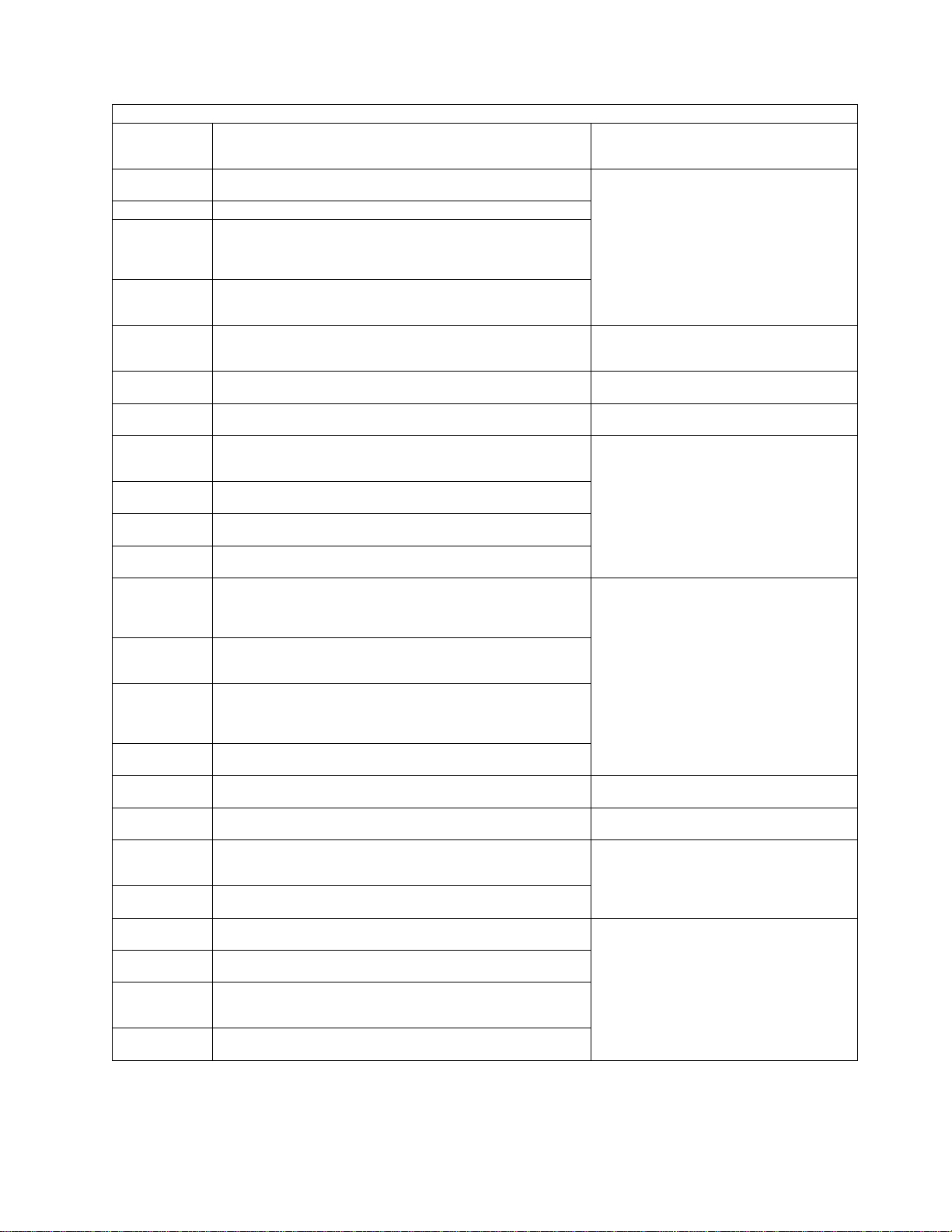
3745 Panel Codes
Table 1-5 (Page 5 of 33). Panel Codes. Anñfollowing a panel code denotes that the code should 'Blink'.
Panel
Code
0DFñ
0E0ñ CHIO TRANSFER KO
0E1ñ
0E2ñ
0E3ñ
0E4ñ
0E5ñ
0E6ñ
0E7ñ
0E8ñ
0E9ñ
0EAñ
0EBñ
0EDñ
0EEñ
0EFñ
0F0 Unused
0F1ñ
0F2ñ
0F3ñ
0F4ñ
0F5ñ
0F6ñ
Definition
IOIRV REGISTER IS X'00' IN TEST 2 NO INTERRUPT REQUESTED
ADAPTER IN BUSY STATE IN TEST 4 BSTAT BITS
0,1 ARE NOT B'00' OR ADAPTER NOT ENABLE
BSTAT BIT 6 IS NOT ONE RUN DIAGNOSTIC
COMMAND TEST
DATA TRANSMISSION ERROR HSTAT BITS
0,1,2,3,6,7 ARE NOT ZERO RUN DIAGNOSTIC
COMMAND TEST
DIFFERENT CONTENTS IN THE FIRST AND THE
SECOND PART OF THE SECTOR BUFFER RUN
DIAGNOSTIC COMMAND TEST
ERROR IN SSB BYTE 0 RUN DIAGNOSTIC
COMMAND TEST
ERROR IN SSB BYTE 1 AND 2 RUN DIAGNOSTIC
COMMAND TEST
ADAPTER IN BUSY STATE IN TEST 5 BSTAT BITS
0,1 ARE NOT B'00' OR ADAPTER NOT ENABLE
BSTAT BIT 6 IS NOT ONE DRIVES INITIALIZATION
IOIRV REGISTER IS X'00' IN TEST 5 NO INTERRUPT RECEIVED DRIVES INITIALIZATION
EIRV REGISTER IS NOT X'00' IN TEST 5 DRIVES
INITIALIZATION
DATA TRANSMISSION ERROR HSTAT BITS
0,1,2,3,6,7 ARE NOT ZERO DRIVES INITIALIZATION
ADAPTER IN BUSY STATE IN TEST 6 BSTAT BITS
0,1 ARE NOT B'00' OR ADAPTER NOT ENABLE
BSTAT BIT 6 IS NOT ONE SEEK COMMAND
BEFORE RECALIBRATE TEST
IOIRV REGISTER IS X'00' IN TEST 6 NO INTERRUPT RECEIVED SEEK COMMAND BEFORE
RECALIBRATE TEST
ADAPTER IN BUSY STATE IN TEST 6 BSTAT BITS
0,1 ARE NOT B'00' OR ADAPTER NOT ENABLE
BSTAT BIT 6 IS NOT ONE RECALIBRATE COMMAND
TEST
IOIRV REGISTER IS X'00' IN TEST 6 NO INTERRUPT RECEIVED RECALIBRATE COMMAND TEST
EIRV REGISTER IS NOT X'00' IN TEST 6 RECALIBRATE COMMAND TEST
DATA TRANSMISSION ERROR HSTAT BITS
0,1,2,3,6,7 ARE NOT ZERO DRIVES INITIALIZATION
RECALIBRATE COMMAND TEST
NO CYLINDER ZERO IN SSB BYTE0 BIT 7 RECALIBRATE COMMAND TEST
ERROR IN SSB BYTE 0 RECALIBRATE COMMAND
TEST
ERROR IN SSB BYTE 1 AND 2 RECALIBRATE
COMMAND TEST
ADAPTER IN BUSY STATE IN TEST 7 BSTAT BITS
0,1 ARE NOT B'00' OR ADAPTER NOT ENABLE
BSTAT BIT 6 IS NOT ONE READ ID COMMAND TEST
IOIRV REGISTER IS X'00' IN TEST 7 NO INTERRUPT RECEIVED READ ID COMMAND TEST
Action: Go to “3745 FRU Group
Table” on page 1-49
or to MAP number
Exchange the FRU group 15
Exchange the FRU group 15
Exchange the FRU group 21
Exchange the FRU group 15
Exchange the FRU group 16
Exchange the FRU group 16
Exchange the FRU group 16
Go to “MAP 3220: Undefined Panel
Message” on page 2-5
Exchange the FRU group 16
Exchange the FRU group 16
Chapter 1. START: How to Begin Troubleshooting 1-19
Page 90

Table 1-5 (Page 6 of 33). Panel Codes. Anñfollowing a panel code denotes that the code should 'Blink'.
Panel
Code
0F7ñ
0F8ñ
0F9ñ
0FAñ ERROR IN SSB BYTE 0 READ ID COMMAND TEST
0FBñ
0FCñ
0FDñ
0FE Unused
0FFñ
100 Unused
101
102
103 to 110 Unused
111ñ
112ñ
113ñ
114ñ
115ñ ERROR IN SSB BYTE 0 SEEK COMMAND TEST
116ñ
117ñ
118ñ
119ñ
11Añ
11Bñ
11Cñ
Definition
EIRV REGISTER IS NOT X'00' IN TEST 7 READ ID
COMMAND TEST
DATA TRANSMISSION ERROR HSTAT BITS
0,1,2,3,6,7 ARE NOT ZERO READ ID COMMAND
TEST
ERROR ON HEAD ADDRESSING MECHANISM READ
ID COMMAND TEST
ERROR IN SSB BYTE 1 AND 2 READ ID COMMAND
TEST
ADAPTER IN BUSY STATE IN TEST 8 BSTAT BITS
0,1 ARE NOT B'00' OR ADAPTER NOT ENABLE
BSTAT BIT 6 IS NOT ONE RECALIBRATE COMMAND
BEFORE SEEK TEST
IOIRV REGISTER IS X'00' IN TEST 8 NO INTERRUPT RECEIVED RECALIBRATE COMMAND
BEFORE SEEK TEST
ADAPTER IN BUSY STATE IN TEST 8 BSTAT BITS
0,1 ARE NOT B'00' OR ADAPTER NOT ENABLE
BSTAT BIT 6 IS NOT ONE SEEK COMMAND TEST
HARD DISK INITIAL STATE IS NOT OK. A
RECOVERY PROCEDURE IS RUNNING.
HARD DISK INITIAL STATE NOT OK (EVEN AFTER
A RECOVERY PROCEDURE).
IOIRV REGISTER IS X'00' IN TEST 8 NO INTERRUPT RECEIVED SEEK COMMAND TEST
EIRV REGISTER IS NOT X'00' IN TEST 8 SEEK
COMMAND TEST
DATA TRANSMISSION ERROR HSTAT BITS
0,1,2,3,6,7 ARE NOT ZERO SEEK COMMAND TEST
DIFFERENT HEAD NUMBERS SEEK COMMAND
TEST
ERROR IN SSB BYTE 1 AND 2 SEEK COMMAND
TEST
ADAPTER IN BUSY STATE IN TEST 9 BSTAT BITS
0,1 ARE NOT B'00' OR ADAPTER NOT ENABLE
BSTAT BIT 6 IS NOT ONE READ/WRITE A SECTOR
COMMAND
IOIRV REGISTER IS X'00' IN TEST 9 NO INTERRUPT RECEIVED READ/WRITE A SECTOR
COMMAND
EIRV REGISTER IS NOT X'00' IN TEST 9
READ/WRITE A SECTOR COMMAND
DATA TRANSMISSION ERROR HSTAT BITS
0,1,2,3,6,7 ARE NOT ZERO READ/WRITE A SECTOR
COMMAND
DIFFERENT WRITTEN AND READ SECTORS
READ/WRITE A SECTOR COMMAND
ERROR IN SSB BYTE 0 READ/WRITE A SECTOR
COMMAND
Action: Go to “3745 FRU Group
Table” on page 1-49
or to MAP number
Exchange the FRU group 16
Exchange the FRU group 16
Go to “MAP 3220: Undefined Panel
Message” on page 2-5
Exchange the FRU group 16
Go to “MAP 3220: Undefined Panel
Message” on page 2-5
Exchange the FRU group 16
Go to “MAP 3220: Undefined Panel
Message” on page 2-5
Exchange the FRU group 16
Exchange the FRU group 16
Exchange the FRU group 16
3745 Panel Codes
1-20 3745 Models 130 to 17A: MIP
Page 91
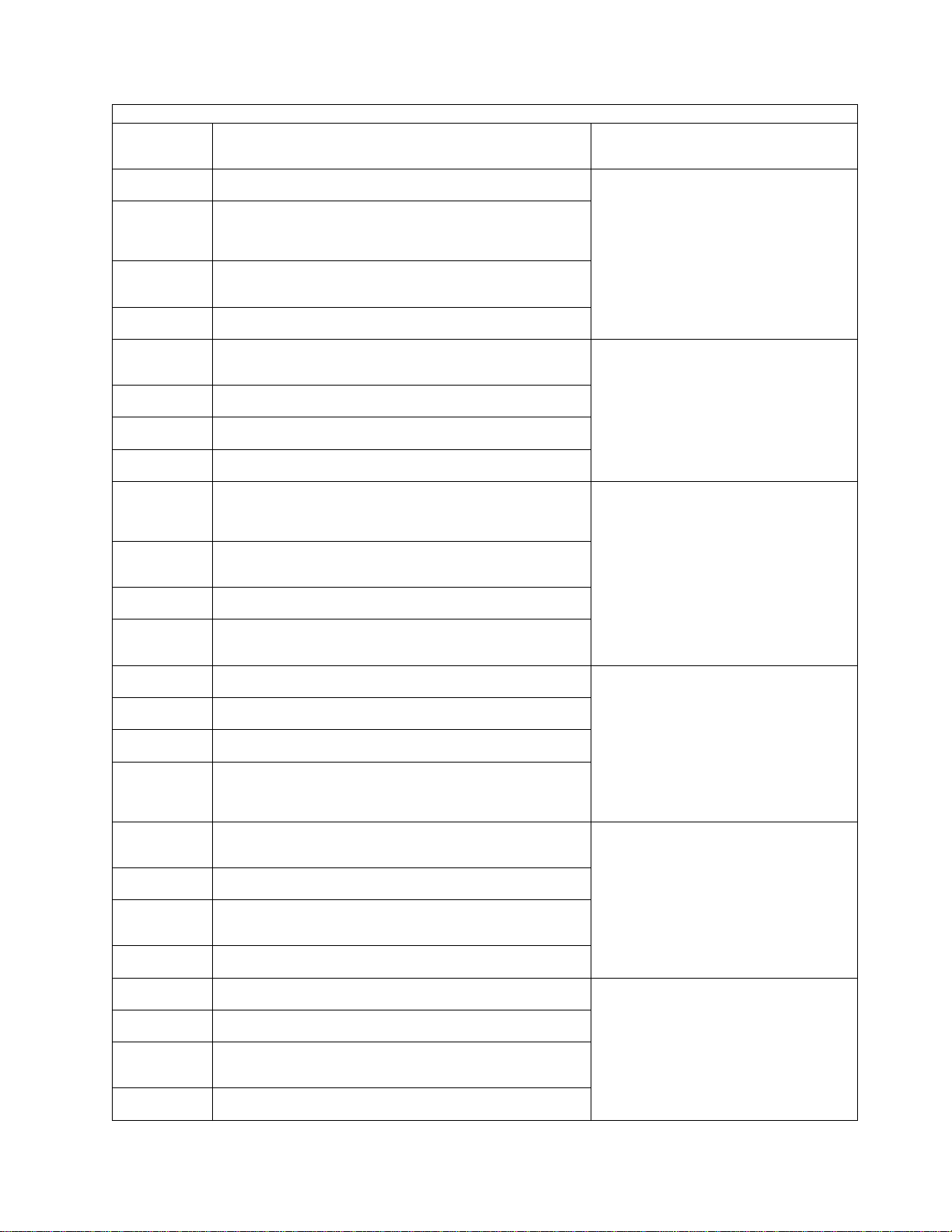
3745 Panel Codes
Table 1-5 (Page 7 of 33). Panel Codes. Anñfollowing a panel code denotes that the code should 'Blink'.
Panel
Code
11Dñ
11Eñ
11Fñ
120ñ
121ñ
122ñ
123ñ
124ñ
125ñ
126ñ
127ñ
128ñ
129ñ
12Añ
12Bñ
12Cñ
12Dñ
12Eñ
12Fñ
130ñ
131ñ
132ñ
133ñ
134ñ
Definition
ERROR IN SSB BYTE 1 AND 2 READ/WRITE A
SECTOR COMMAND
ADAPTER IN BUSY STATE IN TEST 10 BSTAT BITS
0,1 ARE NOT B'00' OR ADAPTER NOT ENABLE
BSTAT BIT 6 IS NOT ONE READ/WRITE A FULL
TRACK COMMAND
IOIRV REGISTER IS X'00' IN TEST 10 NO INTERRUPT RECEIVED READ/WRITE A FULL TRACK
COMMAND
EIRV REGISTER IS NOT X'00' IN TEST 10
READ/WRITE A FULL TRACK COMMAND
DATA TRANSMISSION ERROR HSTAT BITS
0,1,2,3,6,7 ARE NOT ZERO READ/WRITE A FULL
TRACK COMMAND
DIFFERENT WRITTEN AND READ TRACKS
READ/WRITE A FULL TRACK COMMAND
ERROR IN SSB BYTE 0 READ/WRITE A FULL
TRACK COMMAND
ERROR IN SSB BYTE 1 AND 2 READ/WRITE A FULL
TRACK COMMAND
ADAPTER IN BUSY STATE IN TEST 11 BSTAT BITS
0,1 ARE NOT B'00' OR ADAPTER NOT ENABLE
BSTAT BIT 6 IS NOT ONE READ/WRITE NO DATA
COMMAND
IOIRV REGISTER IS X'00' IN TEST 11 NO INTERRUPT RECEIVED READ/WRITE NO DATA
COMMAND
EIRV REGISTER IS NOT X'00' IN TEST 11
READ/WRITE NO DATA COMMAND
DATA TRANSMISSION ERROR HSTAT BITS
0,1,2,3,6,7 ARE NOT ZERO READ/WRITE NO DATA
COMMAND
DIFFERENT WRITTEN AND READ SECTORS
READ/WRITE NO DATA COMMAND
ERROR IN SSB BYTE 0 READ/WRITE NO DATA
COMMAND
ERROR IN SSB BYTE 1 AND 2 READ/WRITE NO
DATA COMMAND
ADAPTER IN BUSY STATE IN TEST 12 BSTAT BITS
0,1 ARE NOT B'00' OR ADAPTER NOT ENABLE
BSTAT BIT 6 IS NOT ONE READ CHECK/WRITE
VERIFY COMMAND
IOIRV REGISTER IS X'00' IN TEST 12 NO INTERRUPT RECEIVED READ CHECK/WRITE VERIFY
COMMAND
EIRV REGISTER IS NOT X'00' IN TEST 12 READ
CHECK/WRITE VERIFY COMMAND
DATA TRANSMISSION ERROR HSTAT BITS
0,1,2,3,6,7 ARE NOT ZERO READ CHECK/WRITE
VERIFY COMMAND
ERROR IN SSB BYTE 0 READ CHECK/WRITE
VERIFY COMMAND
ERROR IN SSB BYTE 1 AND 2 READ CHECK/WRITE
VERIFY COMMAND
DIFFERENT WRITTEN AND READ SECTORS READ
CHECK/WRITE VERIFY COMMAND
ADAPTER IN BUSY STATE IN TEST 13 BSTAT BITS
0,1 ARE NOT B'00' OR ADAPTER NOT ENABLE
BSTAT BIT 6 IS NOT ONE ECC CORRECTION TEST
IOIRV REGISTER IS X'00' IN TEST 13 NO INTERRUPT RECEIVED ECC CORRECTION TEST
Action: Go to “3745 FRU Group
Table” on page 1-49
or to MAP number
Exchange the FRU group 16
Exchange the FRU group 16
Exchange the FRU group 16
Exchange the FRU group 16
Exchange the FRU group 16
Exchange the FRU group 16
Chapter 1. START: How to Begin Troubleshooting 1-21
Page 92

Table 1-5 (Page 8 of 33). Panel Codes. Anñfollowing a panel code denotes that the code should 'Blink'.
Panel
Code
135ñ
136ñ
137ñ
138ñ
139ñ NO CORRECTION ECC CORRECTION TEST
13Añ NO DETECTION ECC CORRECTION TEST
13Cñ ERROR SSB BYTE 0 ECC CORRECTION TEST
13Dñ
13Eñ
13Fñ
140ñ
141ñ
142ñ
143ñ
144ñ
145ñ
146 Unused
147ñ
148ñ
149ñ
14Añ
14Bñ
14Cñ
14Dñ
14Eñ
Definition
EIRV REGISTER IS NOT X'00' IN TEST 13 ECC CORRECTION TEST
DATA TRANSMISSION ERROR HSTAT BITS
0,1,2,3,6,7 ARE NOT ZERO ECC CORRECTION TEST
ERROR ON A SELECTED SECTOR ECC CORRECTION TEST
NO ERROR IN SSB WHILE EXPECTED ECC CORRECTION TEST
ERROR SSB BYTE 1 AND 2 ECC CORRECTION
TEST
DIFFERENT WRITTEN AND READ CONTENTS IN
TEST 13
DISKETTE CHANGE INFORMATION IS NOT
PRESENT
ADAPTER IN BUSY STATE IN TEST 5 BSTAT BITS
0,1 ARE NOT B'00' OR ADAPTER NOT ENABLE
BSTAT BIT 6 IS NOT ONE DRIVES INITIALIZATION
DISKETTE
IOIRV REGISTER IS X'00' IN TEST 5 NO INTERRUPT RECEIVED DRIVES INITIALIZATION DISKETTE
EIRV REGISTER IS NOT X'00' IN TEST 5 DRIVES
INITIALIZATION DISKETTE
DATA TRANSMISSION ERROR HSTAT BITS
0,1,2,3,6,7 ARE NOT ZERO DRIVES INITIALIZATION
DISKETTE
ADAPTER IN BUSY STATE IN TEST 6 BSTAT BITS
0,1 ARE NOT B'00' OR ADAPTER NOT ENABLE
BSTAT BIT 6 IS NOT ONE SEEK COMMAND
BEFORE RECALIBRATE TEST DISKETTE
IOIRV REGISTER IS X'00' IN TEST 6 NO INTERRUPT RECEIVED SEEK COMMAND BEFORE
RECALIBRATE TEST DISKETTE
ADAPTER IN BUSY STATE IN TEST 6 BSTAT BITS
0,1 ARE NOT B'00' OR ADAPTER NOT ENABLE
BSTAT BIT 6 IS NOT ONE RECALIBRATE COMMAND
TEST DISKETTE
IOIRV REGISTER IS X'00' IN TEST 6 NO INTERRUPT RECEIVED RECALIBRATE COMMAND TEST
DISKETTE
EIRV REGISTER IS NOT X'00' IN TEST 6 RECALIBRATE COMMAND TEST DISKETTE
DATA TRANSMISSION ERROR HSTAT BITS
0,1,2,3,6,7 ARE NOT ZERO DRIVES INITIALIZATION
RECALIBRATE COMMAND TEST DISKETTE OR NO
DISKETTE (OR BAD DISKETTE) IN DRIVE
NO CYLINDER ZERO IN SSB BYTE0 BIT 7 RECALIBRATE COMMAND TEST2DRIVE DISKETTE
ERROR IN SSB BYTE 0 RECALIBRATE COMMAND
TEST DISKETTE
ERROR IN SSB BYTE 1 AND 2 RECALIBRATE
COMMAND TEST DISKETTE
ADAPTER IN BUSY STATE IN TEST 7 BSTAT BITS
0,1 ARE NOT B'00' OR ADAPTER NOT ENABLE
BSTAT BIT 6 IS NOT ONE READ ID COMMAND TEST
DISKETTE
Action: Go to “3745 FRU Group
Table” on page 1-49
or to MAP number
Exchange the FRU group 16
Exchange the FRU group 16
Exchange the FRU group 16
Exchange the FRU group 18
Exchange the FRU group 17
Exchange the FRU group 19
Exchange the FRU group 17
Exchange the FRU group 19
Exchange the FRU group 17
Exchange the FRU group 19
Go to “MAP 3220: Undefined Panel
Message” on page 2-5
Exchange the FRU group 17
Exchange the FRU group 17
Exchange the FRU group 19
Exchange the FRU group 21
Exchange the FRU group 17
3745 Panel Codes
1-22 3745 Models 130 to 17A: MIP
Page 93

3745 Panel Codes
Table 1-5 (Page 9 of 33). Panel Codes. Anñfollowing a panel code denotes that the code should 'Blink'.
Panel
Code
14Fñ
150ñ
151ñ
152ñ
154ñ
155ñ
156ñ
158ñ
159ñ
15Añ
15Bñ
15Cñ
15Eñ
15F END OF DISK ADAPTER TEST Progression code.
170
171
172 to 177 Unused
178
179 Unused
17A
17B
17C Unused
17D
Definition
IOIRV REGISTER IS X'00' IN TEST 7 NO INTERRUPT RECEIVED READ ID COMMAND TEST
DISKETTE
EIRV REGISTER IS NOT X'00' IN TEST 7 READ ID
COMMAND TEST DISKETTE
DATA TRANSMISSION ERROR HSTAT BITS
0,1,2,3,6,7 ARE NOT ZERO READ ID COMMAND
TEST DISKETTE
ERROR ON HEAD ADDRESSING MECHANISM READ
ID COMMAND TEST DISKETTE
ERROR IN SSB BYTE 0 READ ID COMMAND TEST
DISKETTE
ERROR IN SSB BYTE 1 AND 2 READ ID COMMAND
TEST DISKETTE
ADAPTER IN BUSY STATE IN TEST 8 BSTAT BITS
0,1 ARE NOT B'00' OR ADAPTER NOT ENABLE
BSTAT BIT 6 IS NOT ONE RECALIBRATE COMMAND
BEFORE SEEK TEST DISKETTE
IOIRV REGISTER IS X'00' IN TEST 8 NO INTERRUPT RECEIVED RECALIBRATE COMMAND
BEFORE SEEK TEST DISKETTE
ADAPTER IN BUSY STATE IN TEST 8 BSTAT BITS
0,1 ARE NOT B'00' OR ADAPTER NOT ENABLE
BSTAT BIT 6 IS NOT ONE SEEK COMMAND TEST
DISKETTE
IOIRV REGISTER IS X'00' IN TEST 8 NO INTERRUPT RECEIVED SEEK COMMAND TEST DISKETTE
EIRV REGISTER IS NOT X'00' IN TEST 8 SEEK
COMMAND TEST DISKETTE
DATA TRANSMISSION ERROR HSTAT BITS
0,1,2,3,6,7 ARE NOT ZERO SEEK COMMAND TEST
DISKETTE
DIFFERENT HEAD NUMBERS SEEK COMMAND
TEST
ERROR IN SSB BYTE 1 AND 2 SEEK COMMAND
TEST DISKETTE
ROS CODE GETS CONTROL FOR A RE-IML BUT
THE RE-IML RESET SEQUENCE IS NOT PERFORMED
RE-IML SEQUENCE COMPLETELY PERFORMED
BUT ERROR IN MOSS PROCESSOR RESET STATE
TEST
CONTROL LOST DURING THE PROCESSING OF
THE 'MOSS DIAGS BY-PASS' REQUEST. A PCC
ERROR IS ALSO SUSPECTED.
INFORMATION DEFINING THE ORIGIN OF THE ACTI
VATION OF THE MOSS DIAGNOSTICS IS NOT
VALID. (RUN THE PANEL TEST TO CHECK THE
CONTROL PA NEL).
CONTROL LOST DURING THE PROCESSING OF
THE 'MOSS DIAGS BY-PASS' REQUEST
STORAGE ACCESS PROBLEM. DUMP REQUEST
CAN NOT BE PROCESSED
Action: Go to “3745 FRU Group
Table” on page 1-49
or to MAP number
Exchange the FRU group 19
Exchange the FRU group 17
Exchange the FRU group 19
Exchange the FRU group 21153ñ
Exchange the FRU group 17
Exchange the FRU group 19
Exchange the FRU group 17
Exchange the FRU group 19
Exchange the FRU group 17
Exchange the FRU group 19
Exchange the FRU group 2115Dñ ERROR IN SSB BYTE 0 SEEK COMMAND TEST
If permanently displayed, exchange
the FRU group 2
Exchange the FRU group 2
Go to “MAP 3220: Undefined Panel
Message” on page 2-5
Exchange the FRU group 22
Go to “MAP 3220: Undefined Panel
Message” on page 2-5
Exchange the FRU group 10
Exchange the FRU group 23
Go to “MAP 3220: Undefined Panel
Message” on page 2-5
Exchange the FRU group 11
Chapter 1. START: How to Begin Troubleshooting 1-23
Page 94

Table 1-5 (Page 10 of 33). Panel Codes. Anñfollowing a panel code denotes that the code should 'Blink'.
Panel
Code
17E Unused
17F
180
181ñ
182
183 to 187 Unused
188
189ñ
18A
18B Unused
18C CONTROL LOST DURING TOD ADAPTER TEST Exchange the FRU group 6
18D
18E to 18F Unused
190 START OF MCC TEST Progression code.
191ñ
192ñ ERROR IN PCA 1 TEST ASYNCHRONOUS Exchange the FRU group 26
193ñ
194ñ
195ñ
196ñ
197ñ ERROR IN PCA 2 TEST ASYNCHRONOUS Exchange the FRU group 26
198ñ UNEXPECTED LEVEL 0 INT. DURING PCA2 TEST Exchange the FRU group 5
199ñ
19Añ UNEXPECTED INT. (<> LEVEL 0) IN PCA2 TEST Exchange the FRU group 6
19Bñ
19Cñ ERROR IN PCA 3 TEST SYNCHRONOUS Exchange the FRU group 26
19Dñ UNEXPECTED LEVEL 0 INT. DURING PCA3 TEST Exchange the FRU group 5
19Eñ
19Fñ UNEXPECTED INT. (<> LEVEL 0) IN PCA3 TEST Exchange the FRU group 5
1A0
1A1
1A2 LOCAL CONSOLE PCA ERROR Exchange the FRU group 26
1A3
Definition
COMPLETION OF ROS PART OF MOSS DIAGNOSTICS Progression code.
ENTRY INTO RAM PART OF MOSS DIAGNOSTICS
Progression code.
CURRENT PROGRAM LEVEL NOT AS EXPECTED
(SHOULD HAVE BEEN 6)
RAM DIAG CONTROLLER HAS FULL CONTROL
Progression code.
CONTROL LOST DURING INSTRUCTION TEST PART
2
MOSS PROCESSOR INSTRUCTION TEST PART 2
NOT OK
MOSS PROCESSOR INSTRUCTION TEST PART 2
SUCCESSFULLY RUN Progression code.
END OF TOD TEST (SUCCESSFUL OR NOT)
Progression code.
HARDWIRED CONDITIONS IMPOSSIBLE TO GET IN
PCA 1
UNEXPECTED LEVEL 0 INTERRUPT DURING PCA1
TEST
ERROR IN PCA 1 INTERNAL WRAP ASYNCHRONOUS TEST.
UNEXPECTED LEVEL 0 INTERRUPT DURING PCA1
TEST
HARDWIRED CONDITIONS IMPOSSIBLE TO GET IN
PCA 2
ERROR IN PCA 2 INTERNAL WRAP ASYNCHRONOUS TEST.
HARDWIRED CONDITIONS IMPOSSIBLE TO GET IN
PCA 3
ERROR IN PCA 3 INTERNAL WRAP SYNCHRONOUS
TEST.
WRAP BLOCK DOES NOT SEEM TO BE PRESENT
ON LOCAL PORT , OR SIGNALS TESTED ARE NOT
OK.
LOCAL CONSOLE CABLE DOWN (WHEN WRAP
BLOCK INSTALLED)
WRAP BLOCK DOES NOT SEEM TO BE PRESENT
ON REMOTE PORT , OR SIGNALS TESTED ARE
NOT OK.
Action: Go to “3745 FRU Group
Table” on page 1-49
or to MAP number
Go to “MAP 3220: Undefined Panel
Message” on page 2-5
If permanently displayed, exchange
the FRU group 24
If permanently displayed, exchange
the FRU group 25
Exchange the FRU group 25
If permanently displayed, exchange
the FRU group 25
Go to “MAP 3220: Undefined Panel
Message” on page 2-5
Exchange the FRU group 25
If permanently displayed, exchange
the FRU group 25
Go to “MAP 3220: Undefined Panel
Message” on page 2-5
If permanently displayed, exchange
the FRU group 2
Go to “MAP 3220: Undefined Panel
Message” on page 2-5
If permanently displayed, exchange
the FRU group 9
Exchange the FRU group 5
Exchange the FRU group 5
Exchange the FRU group 26
Exchange the FRU group 6
Exchange the FRU group 5
Exchange the FRU group 26
Exchange the FRU group 5
Exchange the FRU group 26
Exchange the FRU group 27
Exchange the FRU group 28
Exchange the FRU group 27
3745 Panel Codes
1-24 3745 Models 130 to 17A: MIP
Page 95

3745 Panel Codes
Table 1-5 (Page 11 of 33). Panel Codes. Anñfollowing a panel code denotes that the code should 'Blink'.
Panel
Code
1A4
1A5 REMOTE/ALTERNATE CONSOLE PCA ERROR Exchange the FRU group 26
1A6
1A7
1A8 RSF CONSOLE PCA ERROR Exchange the FRU group 26
1A9 TO
1AF
1B0 COMPLETION OF MCC TEST Progression code.
1B1 START OF LOCAL CONSOLE LINK TEST
1B2 SUCCESSFUL LOCAL CONSOLE LINK TEST
1B3 START OF REMOTE/ALT CONSOLE LINK TEST
1B4 SUCCESSFUL REMOTE /ALT CONSOLE LINK TEST
1B5 START OF RSF CONSOLE LINK TEST
1B6 SUCCESSFUL RSF CONSOLE LINK TEST
1B7 to 1B9 Unused
1D0 START OF MCAC TEST.Progression code.
1D1 Unused
1D2ñ SOLID ERROR IN MCAD REGISTERS (1 FRU )
1D3ñ 100 MS TIMER OF MCAD KO
1D4ñ PERMANENT IR 1 IN IOIRV
1D5ñ PERMANENT IR 4 IN IOIRV
1D6ñ
1D7ñ
1D8ñ Unused
1D9ñ PERMANENT IR 0 IN IOIRV
1DAñ SOLID ERROR IN MCCU REGISTERS
1DBñ SOLID ERROR IN MCCU REGISTERS Exchange the FRU group 26
1DC to
1DF
1E0ñ IOC TAG RESET FUNCTION KO
1E1ñ Unused
1E2ñ WATCHDOG INTERRUPT BIT ON IN MCCU Exchange the FRU group 26
1E3ñ MOSS INOP BIT NOT SETTABLE IN MCCU Exchange the FRU group 5
1E4 to 1E6 Unused
1E7ñ NO INTERRUPT REPORTING POSSIBLE IN MCCU Exchange the FRU group 26
1E8 to 1EE Unused
1EF END OF MCAC TEST Progression code.
1F0 to 1FD Unused
1FEñ Control lost during return to RAM IML processor Exchange the FRU group 25
1FF Completion of MOSS diagnostics RAM part Exchange the FRU group 2
Definition
REMOTE/ALTERNATE CONSOLE CABLE DOWN
(WHEN WRAP BLOCK INSTALLED)
WRAP BLOCK DOES NOT SEEM TO BE PRESENT
ON RSF PORT , OR SIGNALS TESTED ARE NOT
OK.
RSF CONSOLE CABLE DOWN (WHEN WRAP BLOCK
INSTALLED)
Unused
IR LEVEL 1 OF MCAD NOT REPORTED TO MOSS
PROCESSOR.
'MOSS INOP BIT' NOT ON AFTER RESET BY THE
RESET LINE IN MCCU
Unused
Action: Go to “3745 FRU Group
Table” on page 1-49
or to MAP number
Exchange the FRU group 29
Exchange the FRU group 27
Exchange the FRU group 30
Go to “MAP 3220: Undefined Panel
Message” on page 2-5
If permanently displayed, exchange
the FRU group 2
INFORMATION ONLY
INFORMATION ONLY
Go to “MAP 3220: Undefined Panel
Message” on page 2-5
If permanently displayed, exchange
the FRU group 2
Go to “MAP 3220: Undefined Panel
Message” on page 2-5
Exchange the FRU group 26
Exchange the FRU group 5
Exchange the FRU group 26
Go to “MAP 3220: Undefined Panel
Message” on page 2-5
Exchange the FRU group 5
Go to “MAP 3220: Undefined Panel
Message” on page 2-5
Go to “MAP 0100: IOC Bus Trouble
Shooting” on page 2-1
Go to “MAP 3220: Undefined Panel
Message” on page 2-5
Go to “MAP 3220: Undefined Panel
Message” on page 2-5
Go to “MAP 3220: Undefined Panel
Message” on page 2-5
If permanently displayed, exchange
the FRU group 2
Go to “MAP 3220: Undefined Panel
Message” on page 2-5
Chapter 1. START: How to Begin Troubleshooting 1-25
Page 96
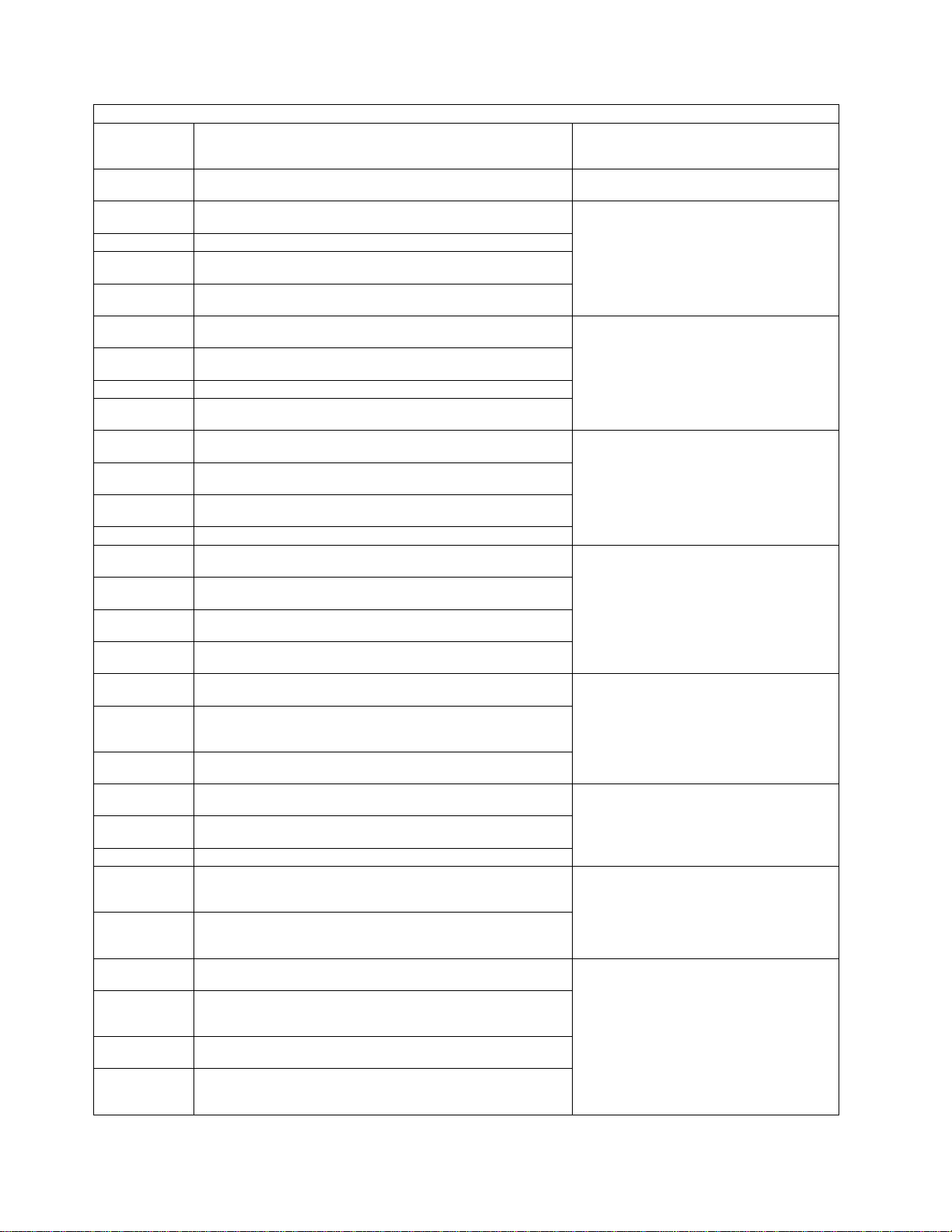
Table 1-5 (Page 12 of 33). Panel Codes. Anñfollowing a panel code denotes that the code should 'Blink'.
Panel
Code
200 to 9FF Unused
A00ñ
A01ñ Moss level 0 error detection; PCA1; Adapter is 'down'
A02ñ
A03ñ
A04ñ
A05ñ
A06ñ Moss level 0 error detection; PCA2; Adapter is 'down'
A07ñ
A08ñ
A09ñ
A0Añ
A0Bñ Moss level 0 error detection; PCA3; Adapter is 'down'
A0Cñ
A0Dñ
A0Eñ
A0Fñ
A10ñ
A12ñ
A13ñ
A14ñ
A15ñ Moss level 0 error detection; MCCU A; CHIO Timeout
A16ñ
A17ñ
A18ñ
A19ñ
A1Añ
A1Bñ
Definition
Moss level 0 error detection; MCCU A or SWAD
Adapter is 'down'; Excess spurious errors
Moss level 0 error detection; PCA1; PIO Bus Check;
Inbound parity
Moss level 0 error detection; PCA1; PIO Bus Check;
Adapter not detected
Moss level 0 error detection; PCA1; PIO Timeout; Outbound; Address parity check
Moss level 0 error detection; PCA1; PIO Timeout; Outbound; Command/data parity check
Moss level 0 error detection; PCA2; PIO Bus Check;
Inbound parity
Moss level 0 error detection; PCA2; PIO Bus Check;
Adapter not detected
Moss level 0 error detection; PCA2; PIO Timeout; Outbound; Address parity check
Moss level 0 error detection; PCA2; PIO Timeout; Outbound; Command/data parity check
Moss level 0 error detection; PCA3; PIO Bus Check;
Inbound parity
Moss level 0 error detection; PCA3; PIO Bus Check;
Adapter not detected
Moss level 0 error detection; PCA3; PIO Timeout; Outbound; Address parity check
Moss level 0 error detection; PCA3; PIO Timeout; Outbound; Command/data parity check
Moss level 0 error detection; MCCU A; Adapter is
'down'
Moss level 0 error detection; MCCU A; Adapter is
'down'; Excess
spurious errors
Moss level 0 error detection; MCCU A; Adapter check;
1 usec counter parity
Moss level 0 error detection; MCCU A; Adapter check;
MIOC/CCU timeout parity
Moss level 0 error detection; MCCU A; CHIO Bus
check
Moss level 0 error detection; MCCU A; CHIO; Storage
ECC error;
Register space parity during main store.
Moss level 0 error detection; MCCU A; CHIO; Storage
ECC error;
Multiple bits in DIV Register
Moss level 0 error detection; MCCU A; CHIO; Storage
ECC error; No bits active in DIV Register
Moss level 0 error detection; MCCU A; CHIO; Exception; Address
exception on main store data access
Moss level 0 error detection; MCCU A; CHIO; Exception; Operation exception; CHCV Register invalid
Moss level 0 error detection; MCCU A; CHIO; Exception; Register
precision; CHP Register bits 0-7 are not zero
Action: Go to “3745 FRU Group
Table” on page 1-49
or to MAP number
Go to “MAP 3220: Undefined Panel
Message” on page 2-5
Exchange the FRU group 5
Exchange the FRU group 5
Exchange the FRU group 5
Exchange the FRU group 5
Exchange the FRU group 5A11ñ
Exchange the FRU group 20
Exchange the FRU group 42
Exchange the FRU group 5. Record
the following action for use if the
problem is not corrected by the FRU
exchange; A MOSS microcode
problem is suspected. Call your
support structure, refer to “Contacting
Support” on page A-1.
3745 Panel Codes
1-26 3745 Models 130 to 17A: MIP
Page 97
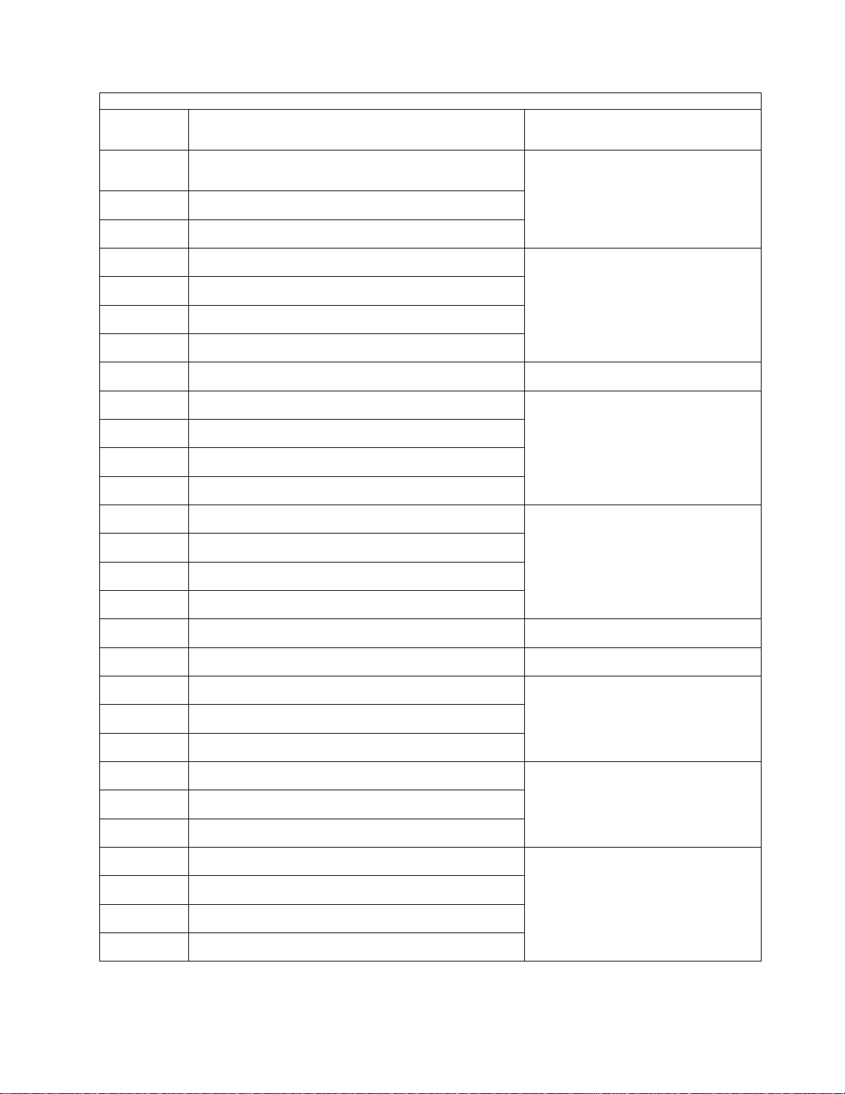
3745 Panel Codes
Table 1-5 (Page 13 of 33). Panel Codes. Anñfollowing a panel code denotes that the code should 'Blink'.
Panel
Code
A1Cñ
A1Dñ
A1Eñ
A1Fñ
A20ñ
A21ñ
A22ñ
A23ñ
A24ñ
A25ñ
A26ñ
A27ñ
A28ñ
A29ñ
A2Añ
A2Bñ
A2Cñ
A2Dñ
A2Eñ
A30ñ
A31ñ
A33ñ
A34ñ
A35ñ
A36ñ
A37ñ
Definition
Moss level 0 error detection; MCCU A; CHIO; Exception; Specification exception with invalid address on
main store data access
Moss level 0 error detection; MCCU A; CHIO; Exception; Multiple bits in DIV Register
Moss level 0 error detection; MCCU A; CHIO; Exception; No bits active in DIV Register
Moss level 0 error detection; MCCU A; CHIO; Internal
check; Cache parity check
Moss level 0 error detection; MCCU A; CHIO; Internal
check; Invalid address on CHP Register access
Moss level 0 error detection; MCCU A; CHIO; Internal
check; Multiple bits in DIV Register
Moss level 0 error detection; MCCU A; CHIO; Adapter
check; Step counter parity
Moss level 0 error detection; MCCU A; CHIO; Adapter
check; Half word/burst counter parity
Moss level 0 error detection; MCCU A; CHIO; Adapter
check; CCU busy; Time out
Moss level 0 error detection; MCCU A; CHIO; Adapter
check; MIOC time out
Moss level 0 error detection; MCCU A; CHIO; Adapter
check; MIOC parity check - in
Moss level 0 error detection; MCCU A; CHIO; Adapter
check; MIOC parity check - out
Moss level 0 error detection; MCCU A; CHIO; Adapter
check; Adapter failure
Moss level 0 error detection; MCCU A; CHIO; Adapter
check; Multiple bits detected in Stat reg
Moss level 0 error detection; MCCU A; CHIO; Adapter
check; No CHIO in progress in Adapter Control Block
Moss level 0 error detection; MCCU A; CHIO; Multiple
bits detected in EIRV reg
Moss level 0 error detection; MCCU A; CHIO; No CHIO
in progress in Adapter Control Block
Moss level 0 error detection; MCCU A; Device; Adapter
check; Step counter parity
Moss level 0 error detection; MCCU A; Device; Adapter
check; MIOC timeout
Moss level 0 error detection; MCCU A; Device; Adapter
check; MIOC parity check - in
Moss level 0 error detection; MCCU A; Device; Adapter
check; MIOC parity check - out
Moss level 0 error detection; MCCU A; Device; Adapter
check; Adapter failure
Moss level 0 error detection; MCCU A; Device; Adapter
check; Multiple bits detected in Stat reg
Moss level 0 error detection; MCCU A; Device; Adapter
check; No Common Adapter Code running
Moss level 0 error detection; MCCU A; PIO; Bus check;
Inbound parity
Moss level 0 error detection; MCCU A; PIO; Bus check;
Adapter failure
Moss level 0 error detection; MCCU A; PIO; Bus check;
Adapter not detected
Moss level 0 error detection; MCCU A; PIO; Timeout;
Invalid command
Action: Go to “3745 FRU Group
Table” on page 1-49
or to MAP number
Exchange the FRU group 5. Record
the following action for use if the
problem is not corrected by the FRU
exchange; A MOSS microcode
problem is suspected. Call your
support structure, refer to “Contacting
Support” on page A-1.
Exchange the FRU group 5
Exchange the FRU group 5
Exchange the FRU group 20
Exchange the FRU group 9
Exchange the FRU group 9
Exchange the FRU group 5
Exchange the FRU group 20A2Fñ
Exchange the FRU group 5A32ñ
Exchange the FRU group 20
Chapter 1. START: How to Begin Troubleshooting 1-27
Page 98
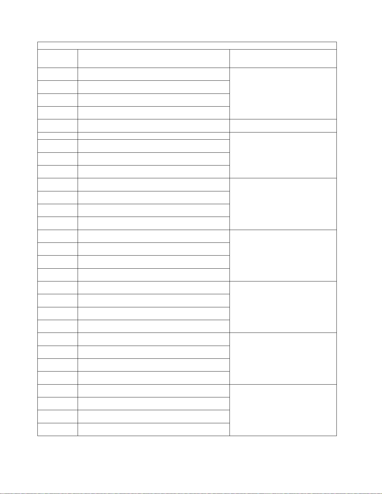
Table 1-5 (Page 14 of 33). Panel Codes. Anñfollowing a panel code denotes that the code should 'Blink'.
Panel
Code
A38ñ
A39ñ
A3Añ
A3Bñ
A3C to A67 Unused
A68ñ Moss level 0 error detection; SWAD; Adapter is 'down'
A69ñ
A6Añ
A6Bñ
A6Cñ
A6Dñ
A6Eñ
A6Fñ
A70ñ
A71ñ
A72ñ
A73ñ
A74ñ
A75ñ
A76ñ
A77ñ
A78ñ
A79ñ
A7Añ
A7Bñ
A7Cñ
A7Dñ
A7Eñ
A7Fñ
Definition
Moss level 0 error detection; MCCU A; PIO; Timeout;
Outbound address parity check
Moss level 0 error detection; MCCU A; PIO; Timeout;
Adapter not detected
Moss level 0 error detection; MCCU A; PIO; Timeout;
Adapter failure
Moss level 0 error detection; MCCU A; PIO; Timeout;
Multiple bits detected in Stat reg
Moss level 0 error detection; SWAD; Adapter is 'down';
Excess spurious errors
Moss level 0 error detection; SWAD; Adapter check;
Internal clock check 1
Moss level 0 error detection; SWAD; Adapter check;
Internal clock check 2
Moss level 0 error detection; SWAD; Adapter check;
Multiple bits detected in Disconnect reg
Moss level 0 error detection; SWAD; Device; Adapter
check; State counter parity
Moss level 0 error detection; SWAD; Device; Adapter
check; Shift pulse counter parity
Moss level 0 error detection; SWAD; Device; Adapter
check; Ground fault detected on a driver line
Moss level 0 error detection; SWAD; Device; Adapter
check; Interface check
Moss level 0 error detection; SWAD; Device; Adapter
check; Interface timeout
Moss level 0 error detection; SWAD; Device; Adapter
check; Interface parity check
Moss level 0 error detection; SWAD; Device; Adapter
check; Multiple bits detected in EB Stat reg
Moss level 0 error detection; SWAD; Device; Adapter
check; Switch interface error
Moss level 0 error detection; SWAD; Device; Adapter
check; Switch driver fault
Moss level 0 error detection; SWAD; Device; Adapter
check; Switch serial link parity
Moss level 0 error detection; SWAD; Device; Adapter
check; Switch invalid command
Moss level 0 error detection; SWAD; Device; Adapter
check; Multiple bits detected in Device stat reg
Moss level 0 error detection; SWAD; Device; Adapter
check; Adapter failure
Moss level 0 error detection; SWAD; Device; Adapter
check; No Common Adapter Code running
Moss level 0 error detection; SWAD; PIO; Bus check;
Inbound parity
Moss level 0 error detection; SWAD; PIO; Bus check;
Adapter failure
Moss level 0 error detection; SWAD; PIO; Bus check;
Adapter not detected
Moss level 0 error detection; SWAD; PIO; Timeout;
Invalid command
Moss level 0 error detection; SWAD; PIO; Timeout;
Outbound address parity check
Action: Go to “3745 FRU Group
Table” on page 1-49
or to MAP number
Exchange the FRU group 20
Go to “MAP 3220: Undefined Panel
Message” on page 2-5
Exchange the FRU group 5
Exchange the FRU group 5
Exchange the FRU group 5
Exchange the FRU group 5
Exchange the FRU group 5
Exchange the FRU group 5
3745 Panel Codes
1-28 3745 Models 130 to 17A: MIP
Page 99

3745 Panel Codes
Table 1-5 (Page 15 of 33). Panel Codes. Anñfollowing a panel code denotes that the code should 'Blink'.
Panel
Code
A80ñ
A81ñ
A82ñ
A83ñ
A84ñ Moss level 0 error detection; MCAD; Adapter is 'down'
A85ñ
A86ñ
A87ñ
A88ñ
A89ñ
A8Añ
A8Bñ
A8Cñ
A8Dñ Moss level 0 error detection; DFA; Adapter is 'down' If loading from diskette (function 9
A8Eñ Moss level 0 error detection; DFA; CHIO Bus check
A8Fñ Moss level 0 error detection; DFA; CHIO time out
A90ñ
A91ñ
A92ñ
A93ñ
A94ñ
A95ñ
A96ñ
A97ñ
A98ñ
A99ñ
A9Añ
A9Bñ
A9Cñ
Definition
Moss level 0 error detection; SWAD; PIO; Timeout;
Overrun
Moss level 0 error detection; SWAD; PIO; Timeout;
Adapter not detected
Moss level 0 error detection; SWAD; PIO; Timeout;
Adapter failure
Moss level 0 error detection; SWAD; PIO; time out;
Multiple bits detected in Stat register
Moss level 0 error detection; MCAD; PIO; Bus check;
Inbound parity
Moss level 0 error detection; MCAD; PIO; Bus check;
Adapter failure
Moss level 0 error detection; MCAD; PIO; Bus check;
Adapter not detected
Moss level 0 error detection; MCAD; PIO; time out;
Invalid command
Moss level 0 error detection; MCAD; PIO; time out; Outbound parity check
Moss level 0 error detection; MCAD; PIO; time out;
Adapter not detected
Moss level 0 error detection; MCAD; PIO; time out;
Adapter failure
Moss level 0 error detection; MCAD; PIO; time out; Multiple bits detected in Stat reg
Moss level 0 error detection; DFA; CHIO; Storage ECC
error; Register space parity during main store.
Moss level 0 error detection; DFA; CHIO; Storage ECC
error; Multiple bits in DIV Register
Moss level 0 error detection; DFA; CHIO; Storage ECC
error; No bits active in DIV Register
Moss level 0 error detection; DFA; CHIO; Exception;
Operation
exception; CHCV Reg invalid
Moss level 0 error detection; DFA; CHIO; Exception;
Register
precision; CHP Reg bits 0-7 are not zero
Moss level 0 error detection; DFA; CHIO; Exception;
Specification exception with invalid address on main
store data access
Moss level 0 error detection; DFA; CHIO; Exception;
Address exception on main store data access
Moss level 0 error detection; DFA; CHIO; Exception;
Multiple bits in DIV Register
Moss level 0 error detection; DFA; CHIO; Exception; No
bits active in DIV Register
Moss level 0 error detection; DFA; CHIO; Internal
check; Cache parity check
Moss level 0 error detection; DFA; CHIO; Internal
check; Invalid address on CHP Reg access
Moss level 0 error detection; DFA; CHIO; Internal
check; Multiple bits in DIV Register
Moss level 0 error detection; DFA; CHIO; Multiple bits
detected in EIRV reg
Action: Go to “3745 FRU Group
Table” on page 1-49
or to MAP number
Exchange the FRU group 5
Exchange the FRU group 5
Exchange the FRU group 5
Exchange the FRU group 5
from the control panel) then exchange
the FRU group 45; if loading from
HDD then exchange the FRU group
46
Exchange the FRU group 43
Exchange the FRU group 15. Record
the following action for use if the
problem is not corrected by the FRU
exchange; A MOSS microcode
problem is suspected. Call your
support structure, refer to “Contacting
Support” on page A-1.
Exchange the FRU group 15. Record
the following action for use if the
problem is not corrected by the FRU
exchange; A MOSS microcode
problem is suspected. Call your
support structure, refer to “Contacting
Support” on page A-1.
If loading from diskette (function 9
from the control panel) then exchange
the FRU group 45; if loading from
HDD then exchange the FRU group
46
Chapter 1. START: How to Begin Troubleshooting 1-29
Page 100
Table 1-5 (Page 16 of 33). Panel Codes. Anñfollowing a panel code denotes that the code should 'Blink'.
Panel
Code
A9Dñ
A9Eñ
A9Fñ
AA0ñ
AA1ñ
AA2ñ
AA3ñ
AA4ñ
AA5ñ
AA6ñ Moss level 0 error detection; TOD; Adapter is 'down'
AA7ñ
AA8ñ
AA9ñ
AAAñ
AABñ Moss level 0 error detection; PLC; Adapter is 'down' Exchange the FRU group 12
AAC to
AAD
AAEñ
AAFñ
AB0 Unused
AB1ñ Moss level 0 error detection; UC Bus; Bus is 'down' Exchange the FRU group 1
AB2ñ
AB3ñ
AB4ñ
AB5ñ
AB6ñ
AB7ñ
AB8ñ
Definition
Moss level 0 error detection; DFA; CHIO; No CHIO in
progress in Adapter Control Block
Moss level 0 error detection; DFA; PIO; Bus check;
Inbound parity
Moss level 0 error detection; DFA; PIO; Bus check;
Adapter failure
Moss level 0 error detection; DFA; PIO; Bus check;
Adapter not detected
Moss level 0 error detection; DFA; PIO; time out; Invalid
command
Moss level 0 error detection; DFA; PIO; time out; Outbound address parity check
Moss level 0 error detection; DFA; PIO; time out; Outbound command/data parity check
Moss level 0 error detection; DFA; PIO; time out;
Adapter failure
Moss level 0 error detection; DFA; PIO; time out; Multiple bits detected in Stat reg
Moss level 0 error detection; TOD; PIO; Bus check;
Inbound parity
Moss level 0 error detection; TOD; PIO; Bus check;
Adapter not detected
Moss level 0 error detection; TOD; PIO; time out; Outbound address parity check
Moss level 0 error detection; TOD; PIO; time out; Outbound command/data parity check
Unused
Moss level 0 error detection; PLC; MMIO Interface error
OR Invalid address during main store data access ( ON
level 2)
Moss level 0 error detection; PLC; MMIO Parity error
OR Memory storage; Storage ECC; Data parity ( ON
level 2)
Moss level 0 error detection; Register Storage; PIO
Storage ECC; Data parity whilst accessing MPC
Moss level 0 error detection; Register Storage; PIO
Storage ECC; Data parity whilst accessing MSC
Moss level 0 error detection; Register Storage; PIO
Storage ECC; Unresolved problem
Moss level 0 error detection; Register Storage; Storage
ECC; Check during PSV swap
Moss level 0 error detection; Memory Storage; CHIO
Storage ECC; Data parity
Moss level 0 error detection; Memory Storage; Storage
ECC; Data parity ( NOT ON level 2)
Moss level 0 error detection; Memory Storage; Storage
ECC; Instruction fetch parity
Action: Go to “3745 FRU Group
Table” on page 1-49
or to MAP number
If loading from diskette (function 9
from the control panel) then exchange
the FRU group 45; if loading from
HDD then exchange the FRU group
46
If loading from diskette (function 9
from the control panel) then exchange
the FRU group 45; if loading from
HDD then exchange the FRU group
46
If loading from diskette (function 9
from the control panel) then exchange
the FRU group 45; if loading from
HDD then exchange the FRU group
46
Exchange the FRU group 2
Exchange the FRU group 2
Go to “MAP 3220: Undefined Panel
Message” on page 2-5
exchange the FRU group 12. Record
the following action for use if the
problem is not corrected by the FRU
exchange; A MOSS microcode
problem is suspected. Call your
support structure, refer to “Contacting
Support” on page A-1.
Exchange the FRU group 12
Go to “MAP 3220: Undefined Panel
Message” on page 2-5
Exchange the FRU group 11. Record
the following action for use if the
problem is not corrected by the FRU
exchange; A MOSS microcode
problem is suspected. Call your
support structure, refer to “Contacting
Support” on page A-1.
Exchange the FRU group 11. Record
the following action for use if the
problem is not corrected by the FRU
exchange; A MOSS microcode
problem is suspected. Call your
support structure, refer to “Contacting
Support” on page A-1.
3745 Panel Codes
1-30 3745 Models 130 to 17A: MIP
 Loading...