

Page 1
Page 2
General
Information
Manual·
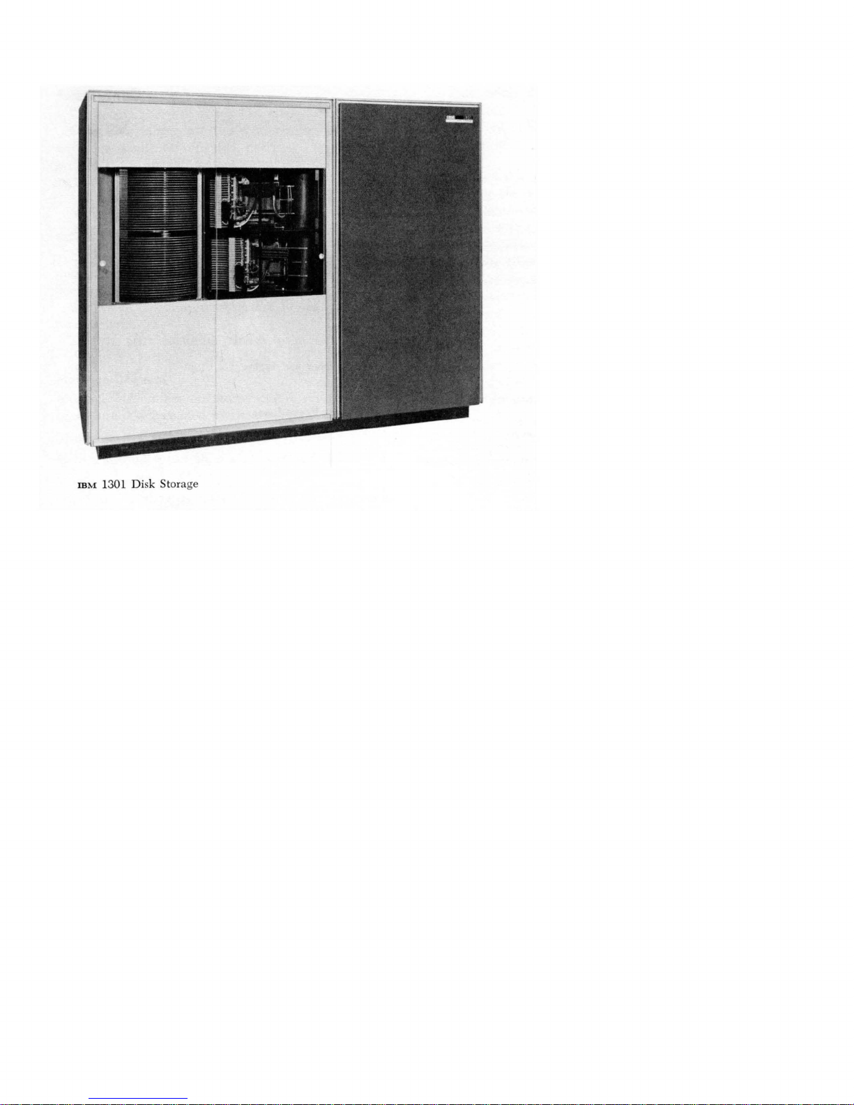
IBM
IBM
1301
7000
Disk
Series
Storage
Data
with
Processing Systems
Page 3
Preface
This
manual
tory information on
Storage
Since
the
length
length
addressing schemes,
out,
and
tempt
to give specific details for these areas; the variations
are
bulletin for
systems
the
7631 File Control has
tions section of this manual.
reader
the
major
is
intended
with
IBM
7000 series
7000 systems include
systems
system
(7070,7074,7090)
(7080),
data
transmission. This
described in a
each
system. Information common to 7000
in
the operation of
to provide general introduc-
the
use of
the
IBM
Data
Processing Systems.
both
and
a variable
minor variations occur
track
capacity, core storage lay-
manual
separate
IBM
1301 Disk Storage
the
1301 Disk Storage
been
included
It
is assumed
has a practical working knowledge of one of
IBM
data
processing systems.
the
in
fixed
does
the
1301 Disk
word
word
in
the
not
at-
and
Opera-
that
the
MAJOR
REVISION
This edition,
and
IBM
N22-0035, N22-0039,
Address comments concerning this
IBM Corporation
Customer Manuals, Dept. 298
P.O.
Box
Poughkeepsie,
© 1961, 1962
(October, 1962)
Form
D22-6576-3, obsoletes Form D22-6576-2,
Technical Newsletters, Forms N22-0029, N22-0031,
and
N22-0061.
390
N.Y.
by
International Business Machines Corporation
manual
to:
Page 4
Contents
Introduction . . . . . . . . . . . . . . . . . . . . . . . . . . . . . . . . . . . .
Magnetic Disk Recording. . . . . . . . . . . . . . . . . . . . . . . . . . .
Functions
Operations
Control
Sense
Write
Read
Checking
Shared System Operation. . . . . . . . . . . . . . . . . . . . . . . . . . .
Instruction Times
Access Motion
.........................................
.....................................
...........................................
.............................................
.............................................
.............................................
..........................................
...................................
Time.
. . . . . . . . . . . . . . . . . . . . . . . . . . . . . .
Control Panel . . . . . . . . . . . . . . . . . . . . . . . . . . . . . . . . . . .
Power-On Switches
and
Lights. . . . . . . . . . . . . . . . . . . . . .
Error Recovery Procedures. . . . . . . . . . . . . . . . . . . . . . .
..
..
" 10
10
12
13
15
16
..
17
18
..
18
..
20
..
20
..
21
5
5
9
Page 5
IBM
1301 Disk Storage
Page 6
IBM
1301
Disk
Storage
High-speed magnetic disk storage provides large external storage capacity to supplement internal core
The
IBM
storage of a computer system.
Storage
and
its associated
IBM
7631 File Control pro-
1301 Disk
vide very large storage capacity, fast access time to
the
disks,
and
data recorded on
the ability to handle
fixed or variable length records.
Significant advantages are:
1.
Lower cost
2.
Entire program libraries contained in readily
per
character of storage.
accessible form.
3.
Access to any program or active file
in
50-180
milliseconds.
4.
Table storage.
5.
Simplification of program scheduling.
6.
Ability to
dump
and
recover files into or from
core storage rapidly.
7.
Customer control of addressing schemes
and
record length format.
8.
Improved checking techniques - more reliable
data
recording.
The
1301
Disk Storage
are available for use with
and
1410
7090,
The
1301
Data
Disk Storage
and
the
7631 File Control
the
IBM
7070, 7074, 7080,
Processing Systems.
is
available in two models:
:Model 1 - single module, providing capacity for
28,000,000 (7080)
characters-or,
using
packed format, 43,300,000 digits.
Model 2 - two modules, providing capacity for
56,000,000 (7080) characters - or, using
packed format, 86,600,000 digits.
The
7631 File Control
1-
Model
for use with a 1410 system
Model 2 - for use
is
available in four models:
with
a 7000 system (7070,
7074,7080, 7090)
Model 3 - for shared use with a 7000 system
and
a 1410 system
Model 4 - for shared use with two 7000 systems
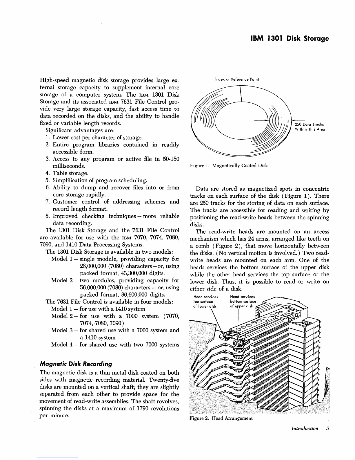
Index or Reference Point
~
250
Data Tracks
Within This Area
Figure
1.
Magnetically
Data
are stored as magnetized spots in concentric
tracks on each surface of
Coated
Disk
the
disk
(Figure
1).
There
are 250 tracks for the storing of data on each surface.
The
tracks are accessible for reading and writing
positioning
the
read-write heads between
the
by
spinning
disks.
The read-write heads are mounted. on an access
mechanism which has 24 arms, arranged like
a comb
the disks.
(Figure
(No
2),
that
move horizontally between
vertical motion
is
involved.)
write heads are mounted on each arm. One of
heads services
while
the
lower disk. Thus, it is possible to
other
the
bottom surface of the
head
services
the
top
read
teeth
Two
upper
surface of
or write on
on
read-
the
disk
the
either side of a disk.
Head
services
Head servi
bottom
of
ces
surface
upper disk
Magnetic Disk Recording
The
magnetic disk is a thin metal disk coated on
sides with magnetic recording material. Twenty-five
disks are mounted on a vertical shaft; they are slightly
separated from each other to provide space for
movement of read-write assemblies.
spinning
per
the
minute.
disks
at
a maximum of 1790 revolutions
The
shaft revolves,
both
the
Figure
2.
Head
Arrangement
Introduction 5
Page 7
The
magnetic disk
tively.
track, the old
corded.
desired;
until
provides external storage capacity
ternal core storage of a computer. Disk storage has a
major advantage, however, in
tained in
random
is, faster access to
the track
records
be
data
arrangement
ments. Addresses must
track
also, space
separate address
for
fining
areas. for
monitors 40 associated
can
data
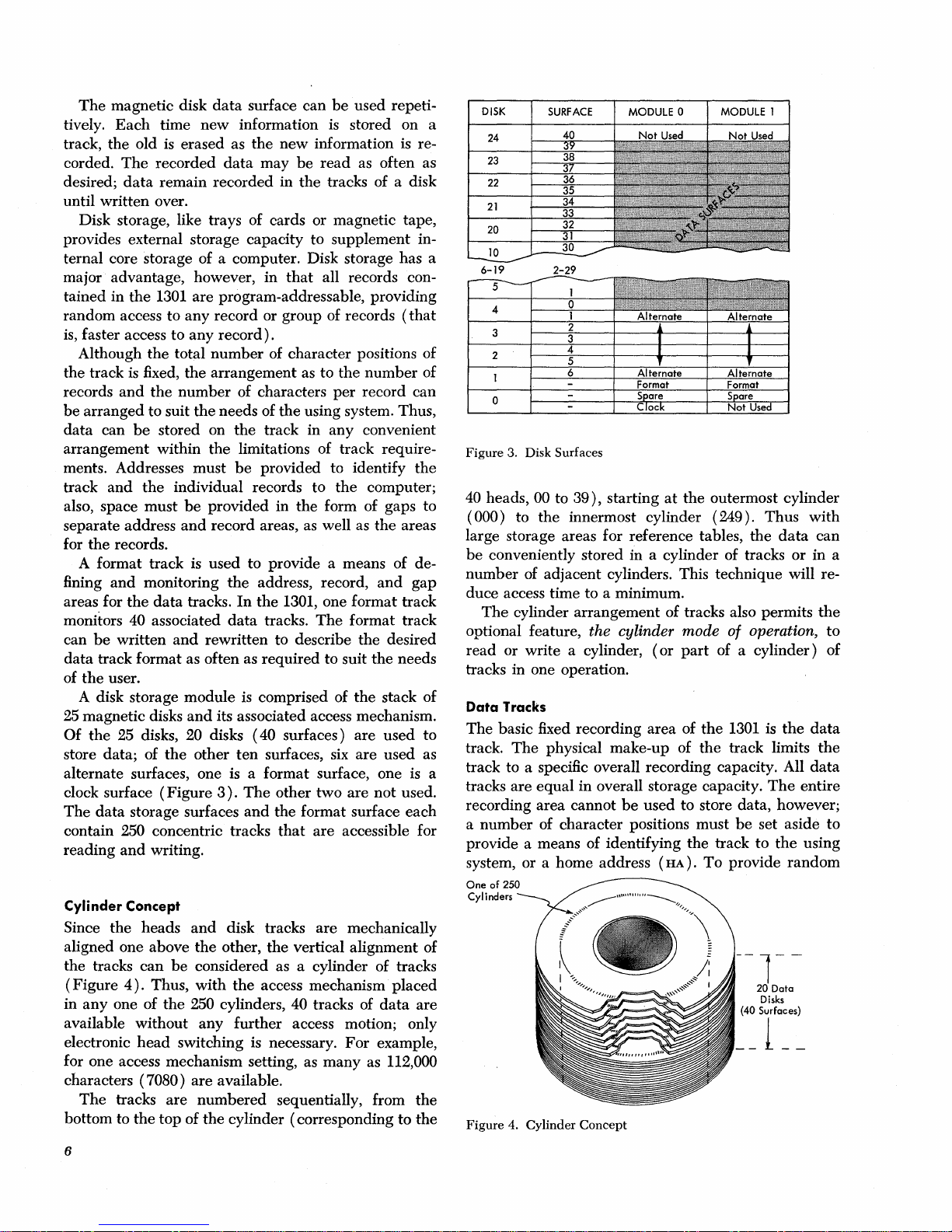
of
25 magnetic disks
Of
store data; of
alternate surfaces, one is a format surface, one is a
clock surface
The
contain 250 concentric tracks
reading
Cylinder Concept
Since
aligned one above
the tracks
(Figure
in
available without
electronic
for one access mechanism setting, as
characters (7080)
bottom to
Each
time
is
The
recorded
data
remain
written
Disk storage, like trays of cards or magnetic tape,
Although
arranged
can
and
the
A format track is used to provide a means of de-
be
track format as often as
the
A disk storage
the
data
anyone
The
over.
the
1301 are program-addressable, providing
access to
the
is
fixed,
and
the
to suit
be
stored on
within
the
must
records.
and
monitoring
the
data
written
user.
25 disks, 20 disks
the
(Figure
storage surfaces
and
writing.
the
heads
can
4).
Thus,
of
the
head
tracks
the
top
data
surface can
new
information
erased as
any
any
total
the
number
the
individual records to
be
and
tracks.
and
module
and
other
and
the
be
considered as a cylinder of tracks
with
250 cylinders, 40 tracks of
any
switching is necessary.
are
are
numbered
of
the
the
new
data
may
recorded
record or group of records
record).
number
arrangement
needs of
the
provided
record areas, as well as
the
data
rewritten to describe
its associated access mechanism.
3).
disk tracks
other,
the
available.
cylinder (corresponding
in
of character positions of
of characters
the
the
track in any convenient
limitations of track require-
be
provided to identify
in
address, record,
In
the
1301, one format track
tracks.
required
is
comprised of
(40
surfaces)
ten
surfaces, six
The
other
and
the format surface
that
the
access mechanism
further
sequentially, from
be
used repeti-
is
stored on a
information
be
read
as often as
the
tracks of a disk
to
supplement in-
that
all records con-
as to
the
number
per
record can
using system. Thus,
the
computer;
the
form of gaps to
The
format
the
to
suit
the
are
are
two
are
are
accessible for
are
mechanically
vertical alignment of
access motion; only
For
many
as 112,000
is
re-
(that
the
the
areas
and
gap
track
desired
the
needs
stack of
used
used as
not
used.
each
placed
data
are
example,
the
to
the
of
to
Figure
3. Disk Surfaces
40 heads, 00 to
(000) to
large storage areas for reference tables,
be
conveniently stored in a cylinder of tracks
number
duce access time to a minimum.
optional feature, the cylinder mode of operation,
read
tracks in one operation.
Data
The
track.
track to a specific overall recording capacity. All
tracks
recording area cannot
a
provide a means of identifying
system, or a home address (
One
Cylinders
Figure
of adjacent cylinders. This technique will re-
The
cylinder
or write a cylinder,
Tracks
basic fixed recording area of
The
are
number
of
250
4. Cylinder
39),
starting
the
innermost cylinder (249).
arrangement
physical make-up of
equal
in overall storage capacity.
of character positions must
Concept
at
the
outermost cylinder
of tracks also permits
(or
part
the
the
be
used to store data, however;
the
track
HA).
To
Thus
the
data
or
of a cylinder) of
1301 is
track limits
be
provide
--1-
__
the
The
set aside
to
the
random
20 Data
Disks
(40 Surfaces)
1
__
entire
using
-
with
can
in a
the
to
data
the
data
to
6
Page 8
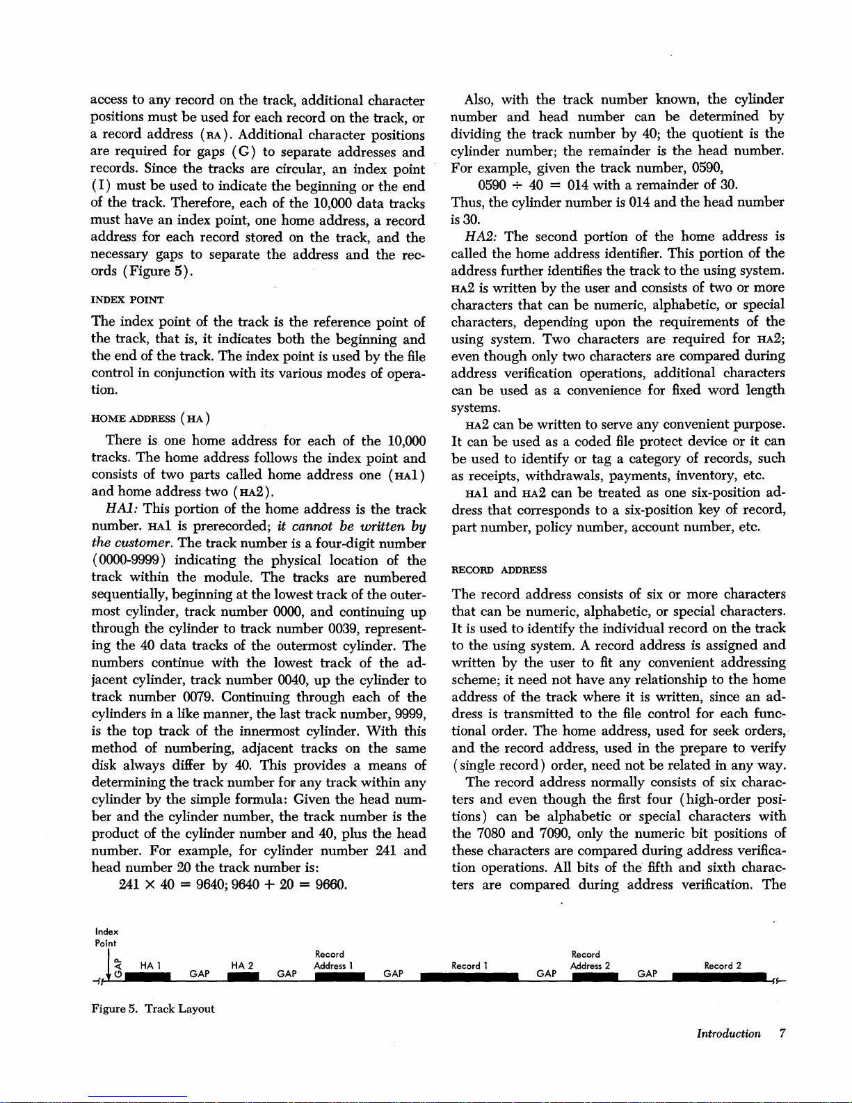
access to any record on the track, additional character
positions must
a record address
are required for gaps
be
used for each record on
(RA).
Additional character positions
(G)
to separate addresses
the
track, or
and
records. Since the tracks are circular, an index point
I)
must
be
(
used to indicate
of the track. Therefore, each of the 10,000
the
beginning or
data
the
tracks
end
must have an index point, one home address, a record
the
track,
and
the rec-
by
the
the
and
file
address for each record stored on
necessary gaps to separate
ords (Figure
INDEX
POINT
The
index point of the track is the reference point of
the track,
the end of the track.
that
5).
is,
it
indicates
The
the
address
both
index point
and
the beginning
is
used
control in conjunction with its various modes of operation.
HOME
ADDRESS
There is one home address for each of
tracks.
The
(HA)
home address follows
the
index point
the
10,000
and
consists of two parts called home address one (HAl)
and
home address two (HA2).
HAl:
This portion of the home address is the track
number.
the customer.
(
0000-9999) indicating the physical location of the
track within
sequentially, beginning
most cylinder, track number
through
ing
the
HAl
is prerecorded; it cannot be written
The
track number
the
module.
at
the
cylinder to track number 0039, represent-
40
data
tracks of the outermost cylinder. The
is
a four-digit number
The
tracks are numbered
the lowest track of
0000,
and
continuing
the
by
outer-
up
numbers continue with the lowest track of the adjacent cylinder, track number
track number
0079. Continuing through each of
cylinders in a like manner,
is
the top track of
the
method of numbering, adjacent tracks on
disk always differ
determining
cylinder
ber
and
product of
the
by
the
the
cylinder number, the track
the
by
40.
track number for any track within any
simple formula: Given the
cylinder number
number. For example, for cylinder
head number
241 X 40
20
the track number is:
= 9640; 9640 +
0040,
up
the
cylinder to
the
last track number, 9999,
innermost cylinder.
With
the
This provides a means of
head
number
and
40, plus the
20
= 9660.
number
241
the
this
same
num-
is the
head
and
Also, with the track number known,
and
head
number
dividing the track number
number can
by
cylinder number; the remainder
be
40; the quotient is
is
For example, given the track number,
40
0590 +
Thus, the cylinder number
is
30.
HA2:
The
= 014 with a remainder of 30.
is
014 and
second portion of the home address is
called the home address identifier. This portion of
address further identifies the track to
HA2
is
written
characters
that
by
the user
can
and
consists of two or more
be
numeric, alphabetic, or special
the
determined
the
head
0590,
the
head
the
using system.
cylinder
by
the
number.
number
the
characters, depending upon the requirements of the
using system. Two characters are required for
HA2;
even though only two characters are compared during
address verification operations, additional characters
can
be
used as a convenience for fixed word length
systems.
HA2
can
be
written to serve any convenient purpose.
It
can
be
used as a coded
be
used to identify or tag a category of records, such
file
protect device or
it
can
as receipts, withdrawals, payments, inventory, etc.
HAl
and
HA2
can
be
treated as one six-position ad-
dress
that
corresponds to a six-position key of record,
part
number, policy number, account number, etc.
RECORD ADDRESS
The
record address consists of six or more characters
that
can
be
numeric, alphabetic, or special characters.
It
is
used to identify the individual record on
to the using system. A record address is assigned
written
scheme;
address of
dress
tional order.
and
(single record) order, need not
ters
tions) can
the 7080
by
the
user to
it
need not have any relationship to the home
the
track where
is
transmitted to the
The
the record address, used
The
record address normally consists of six charac-
and
even though the first four (high-order posi-
be
alphabetic or special characters
and
7090, only
fit
any convenient addressing
it
is
written, since an ad-
file
control for each func-
home address, used for seek orders,-
in
the prepare to verify
be
related in any way.
the
numeric
the
bit
positions of
track
and
with
these characters are compared during address verification operations. All bits of the' fifth
ters are compared during address verification.
and
sixth charac-
The
Index
Point
~
-{
Figure
HA 1
~
5. Track Layout
GAP
HA 2
GAP
Record
Address 1
GAP
Record t
Record
Address 2 Record 2
GAP
GAP
Introduction 7
Page 9

7070
and
7074 use
only the first six digits
GAP
To
distinguish between addresses
are written between address
gaps contain check characters
ization information required for
ten
digits for record addresses,
(high
order)
are verified.
and
records, gaps
and
record areas.
and
internal synchron-
proper
machine opera-
but
The
tion.
Data
are
read
and
written on a track
characters or "bytes" serially
character.
The
8-bit mode permits
by
in
6-bit or 8-bit
bit
and
the
use of packed
serially
by
format feature (packing two 4-bit digits into one 8-bit
character) on the
ture.
Data
characteristics of disk storage are shown
in
Figure
6.
system using
that
fea-
1301
by
any
Since there are 250 tracks on each of the 40 disk
storage surfaces
a module, 10,000 addressable
data
in
tracks are available in each module.
Format Track
Before
the
disk module can
be
used for reading or
writing, certain preparative activities are necessary.
These activities can
trol panel for unit record machines or
be
likened to
the
wiring of a con-
to
the
housekeeping preparations for a program. Preparations involve writing a format track
or instruction) for each cylinder of the module.
format track permits
tain limits, how
cylinder is to
established,
and
control for the subsequent reading or writing of
data
for
that
be
the
cylinder.
the
the
storage space of the tracks of a
allocated, identified,
format track provides a fixed format
(by
means of a command
user to designate, within cer-
and
used. Once
To
alter
the
fixed format
The
and
control for
a
new
The
organized
gramming is used to transmit
to
age
a format track are given
anyone
format track
data
used
in
the
addressed format track. Details on writing
of
the
250 cylinders requires
be
written for
to
create a format track
core storage as a
the
under
that
cylinder.
data
data
from core stor-
Write
Format
must
record. Pro-
that
first
Track
be
Operation.
The
writing of
under
complete control of
format remains fixed until
unintentional changes to
and
the
layout of
the
format track is
the
user. Once written,
it
is rewritten. To prevent
the
format tracks, each
the
module is provided with a two-position key-lock
switch. A format track cannot
key-lock switch is placed
the
mally
Track Capacity
Each
bit
switch
track
character positions available for
is
in
in
a module has 2840 six-bit or 2205 eight-
the
in
READ
the
written unless
WRITE
position.
the
position; nor-
recording of
the
be
information. Character positions necessary for home
the
address two,
considered, however,
record addresses,
in
determining
character positions available for
eral,
the
track area available to store
total track capacity less
sary for addresses
The
track capacity for
mum
when writing a single record on
and
the
character positions neces-
gaps.
any
tracks containing a single record,
and
the
the
records.
the
system is
the
gaps must
number
records is
at
the
the
track.
In
be
of
gen-
the
maxi-
For
track capacity
for each system is:
System
7070 and 7074
7080
7090
6-Bit
2,780
2,800
2,796
8-Bit
2,150
2,165
2,160
Packed
4,310
4,330
Does not apply
Characteristics* 7070-7074 7080
Maximum Characters per Track
Maximum Characters per
Maximum Characters per
(2 Modules)
Maximum Characters per File Control
(5-1301's)
Character
* Figures represent
Figure 6.
8
Rate
Data
Cyl
inder
Disk
Storage
maximum
Characteristics of Disk Storage
uti! ization of space (each track written with a single record)
55,600,000
278,000,000
Six-Bit Mode
2,780 2,800
111,200 112,000
56,000,000
280,000,000
90,100 char/sec
7090 Packed
2,796
111,840 172,400
55,920,000
279,600,000
86,200,000
430,000,000
7070-7074
4,310
140,200
digit/sec
Unpacked
2,150
86,000
43,000,000
215,000,000
70,100
char/sec
Eight-Bit Mode
7080
Packed Unpacked
4,330
173,200
86,600,000
433,000,000
140,200 70,100
digit/sec
43,300,000 43,200,000
216,500,000
2,165
86,600
char/sec
7090
2,160
86,400
216,000,000
70,100
char/sec
Page 10

Functions
The
function performed
1301 Disk Storage,
based
are
and
on
orders, defined as follows:
and
the
execution of instructions, commands,
Instruction: An instruction
that
tion
essing unit to perform a specific function.
is decoded
Command: A command
that
is
decoded
perform a specific function.
the
use
decoded
in this case)
term commands.)
Order:
An order is control-coded information
and
and
executed
to
perform a specific function.
by
the
using system's
and
executed
is
executed
by
a control
the
7631 File Control,
data
channel
is
system-coded informa-
by
the
central proc-
system-coded information
by
the
data
channel to
(The
7080 system does not
that
unit
(file control,
In the following description the word "command"
means "instruction" when applied to the
The
file control can execute
mands
plicable
which
Read
circuits in
mission of
puter
mand
control to
age
transmit orders to
Orders
Orders are transmitted to
command of
are normally transmitted.
the information as
of
using this file control, although
they
code
address information is not required,
of
of
channel as BCD characters.
accepts
the
(read,
data
the
and
system
causes transmission of status
and
Transmission of orders to
the
command is
are initiated
Orders normally consist of a two digit operation
and
the
operation code only. Figure 7 shows
the
order.
Orders
the
order (operation code, access
write, sense,
processing system defines
four commands are issued to the file control.
write commands set
the
connecting
data
between
through
the
computer to indicate status of disk stor-
file control.
the
eight characters to define addresses.
are
transmitted from
digit portion of
the
The
the
file control.
computer in
an
order, decodes it,
the
same for all computer systems
may
be
anyone
and
up
data
channel to
disk storage
file control.
control command
the
file control
the
same
The
file control recognizes
the
file control as a result
the
different.
the
The
the
first eight characters of
and
7080
system.
of four com-
control) .
necessary control
The
data
method
the
computer's
7631 File Control
module number,
The
the
method
permit
and
from
manner
and
order consists
trans-
the
com-
sense com-
the
is
used to
by
a control
as
executes it.
by
which
When
the
make-up
ap-
by
file
data
data
Operation Code
Access and Module Number
G'
'Xx'
'XX
Figure 7. Order
and
the
first four positions of
the
ninth
in
and
xxxxxx'
"'~d
Add,""
the
address)
tenth
characters of
the
Operation Code: A two-digit code
operation to
is
is
always numeric.
required for
mode, eight-bit mode,
be
performed. This portion of
The
operation code is all
the
following orders:
and
no
release.
Access and Module Number: These two positions of
the
order, always numeric, specify
the
operation will take place.
Record
gives
type of operation
Operation Signals
Since disk storage operation takes advantage of
interrupt feature of
generated to provide a communication link
the
erated
Attention: Indicates
operation has successfully positioned
anism
head.
End: Indicates
operation. This signal can indicate
mission of
cate
operation.
or
Home Address: This portion of
the
home or record address, depending
that
is
to take place.
the
7000 series systems, signals are
file control
to indicate a specific condition exists, are:
at
the
the
and
the
computer.
that
specified location
the
successful completion of
an
order to
successful completion of a
the
the
The
a previously given seek
and
selected
the
file control, or
Unusual End: Always indicates
operation. This signal can indicate
been
sensed
other check condition has occurred, or
that
cate
occurred.
Stop: Indicates
of a
read
the
record definition
the
from
and
from
during a read
an
unsuccessful
that
or. write field.
sensing of a group mark in a 7080 system;
word
count
or write operation, or any
attempt
the
computer has sensed
The
word
in a 7070 or 7074 system;
equal
zero in a 7090 system.
that
to
stop signal results from
and
all bits
order.
that
specifies
operation, six-bit
module in which
signals, gen-
the
access mech-
the
successful trans-
it
read
an
unsuccessful
an
it
might
transmit
the
the
order
that
the
order
upon
the
the
between
desired
an
can indi-
or write
error has
indi-
data
has
the
end
is
Introduction 9
Page 11

Operations
The four basic commands used to perform all disk
and
file
storage
write
and
control operations are: control, sense,
read.
Control
The
7631
File Control will decode
13
orders transmitted from the computer
trol command.
The
7631
decodes
accepts address information, performs the designated
function,
signal to the computer.
file
order.
and
then transmits
control sends
It
then performs the seek,
the
In
the case of a seek order,
END
signal after decoding
tion of the seek operation, sends an
to the computer.
The orders consists of two or ten characters.
operatIons where addresses are not required, only a
two-digit operation code
Orders requiring
the
is
two digit operation code only are:
no operation, release, six-bit mode,
The
orders, with their mnemonic code
numeric operation code are shown in Figure 8.
No Operation (DNOP-OO)
This order requires only
The order
is
accepted
by
the
the
convenience only. No function
7631
for this order.
Order
No
Operation
Release
Eight-Bit
Mode
Six-Bit
Mode
Seek
Prepare
to
Verify,
Single
Prepare
to
to
Prepare
to
Prepare
(Optional
Prepare
to
Set Access
Prepare
to
to
Prepare
Figure
Write,
Verify,
Verify,
Feature)
Write
Inoperative
Verify,
Verify,
8.
Table of Orders
Record
Format
Track with
Cyl
Check
Track with Addresses
Home Address
inder
No
Operation
Addresses
and
execute any of
by
the
con-
the
transmitted order,
an
END
or
UNUSUAL
END
the
the
and
at
the comple-
ATTENTION
signal
For
sent to the file control.
and
eight-bit mode.
and
their
two-digit operation code.
7631
as a programming
is
performed
Mnemonic
Code
DNOP
DREL
DEBM
DSBM
DSEK
DVSR
DWRF
DVTN
DVCY
DWRC
DSAI
DVTA
DVHA
by
the
Numeric
Code
00
04
08
09
80
82
83
84
85
86
87
88
89
Release (DREL-04)
This order requires only
The
order has meaning only for shared system operation. Whenever either system selects
of the 7631,
the release order
be
available for either system.
to
Eight-Bit Mode (DEBM-08)
it
remains in control of
is
This order requires only
The
order conditions the
eight-bit mode. This mode of operation
the
when
using system
format mode. Packed format
numeric digits into one eight-bit character.
data rate of the
70,
100 characters
file
per
data characters for
packed format, however,
second with a maximum of 4,330 digits for a
the
two-digit operation code.
and
gains control
that
system until
issued, permitting the file control
the
two-digit operation code.
file
control to operate
is
operating in the packed
is
the packing of two
is
required
The
in
the
normal
control in the eight-bit mode is
second with a maximum of 2,165
data
track capacity; when using
data
rate
is
140, 200 digits
data
per
track
capacity.
Six-Bit Mode (DSBM-09)
This order requires
The
order conditions
six-bit mode.
operating in the six-bit mode
The
the
two-digit operation code only.
the
file
control to operate in
data
rate for the file control when
is
90,100 characters
the
per
second with a maximum track capacity of 2,800 characters.
Seek
(DSEK-80)
The
order for this operation causes the specified access
mechanism of the addressed module to locate itself
the
proper cylinder
When
the
order has
it
signals
END
and
its own routine while disk storage executes
operation. A seek may
mechanisms on
same
file
control. An
seek
is
given to
the
access mechanism
Upon completion of a seek operation,
signal
is
sent to the computer.
ciated with the access mechanism
to indicate this condition. This indication
of
the
status
data
command.
The
access is serviced
and
to select the desired head.
been
received
by
the
file
control,
allows the computer to continue with
the
seek,
be
directed to other access
the
disk storage units attached to
UNUSUAL
an
access mechanism in motion or
is
inoperative.
END
signal results if a
an
In
addition, a
is
set in status
is
ATTENTION
bit
asso-
data
sent as
part
transmitted in response to a sense
attention indicator
by
either a prepare to verify order
is
reset when
the
the
or another seek order.
The
seek order, preceding a cylinder or full track
order,
is
not necessary when the current setting of the
at
if
10
Page 12

access mechanism corresponds to the desired address.
Also, a seek order
single-record operations on
Prepare to Verify, Single
The
order for this operation conditions
for a single-record type of operation
the
following functions:
l.
Select
2.
Specify
3.
Prepare to transmit
record
need
not
be
repeated for consecutive
the
same track.
Record
the
desired module
the
address to
in
response to a subsequent
be
data
and
verified.
from or to
(DVSR-82)
the
file control
and
to
access mechanism.
the
addressed
read
perform
or write
command.
The
order sent to
tion
with
the
specify the
unit
anism is already located
and
the
desired
operation,
the
the
file
control is
command. Access
to
be
selected. Since
and
head
is selected
held
and
in
by
remainder of the order
used
in
conjunc-
module
the
access mech-
the
track position
the
previous seek
is
used for verifi-
number
cation purposes only.
The
file control
each record address as
against
the
address furnished
(in
single-record
it
comes under
by
mode)
the
the
order until
compares
read
head
the
desired address is found.
Information can
areas only as defined
writing continues until either a
the
computer or
record, depending
mand
is being executed.
Prepare to Write, Format (DWRF-83)
This order conditions
track for
of
the
the
order
insignificant).
two-position key-lock switch must
position;
the
addresses of
order must precede
Prepare to Verify, Track with
(DVTN-84)
This order, followed
mits
the
reading or writing of only
particular track; all addresses are skipped over.
address portion of this order must specify
be
read
from or written into record
by
format tracks. Reading or
STOP
signal is issued
the
file control recognizes
upon
whether a
the
file control to write a format
cylinder specified
(the
last two positions of this order are
To
address a format track,
by
read
the
be
track address must
the
cylinder. To write a format track, this
the
write command.
by a read
be
No
Addresses
or write command, per-
the
or write com-
address portion
the
in
the
one of the track
the
records on a
the
by
end
of
format
WRITE
The
home
address.
This order instructs
the
file control to
do
the
fol-
lowing:
l.
Select
the
2.
Supply
desired module
the
home address to
and
access mechanism.
be
verified.
3.
To receive or transmit only
sponse to a subsequent
Reading or writing begins
ing
the
home address,
and
records skipping over addresses until
signals
point. Non-verification of
an
STOP
UNUSUAL
or
the
file control recognizes
the
END
signal, with no transmission of
the
records
read
or write command.
at
the
first record follow-
continues through
the
computer
the
home address results
data
in
re-
the
index
in
to
or from disk storage.
Prepare to Verify, Cylinder Operation
This
is
an optional feature.
(DVCY-85)
It
permits reading or
writing of data (skipping over addresses), beginning
at
the
first record after
dressed track
ord locations
the
end
STOP.
This order is always followed
command.
and
and
the
of cylinder
The
following functions are performed in
the
home address of
the
ad-
continuing through successive rec-
tracks of the cylinder until either
is
reached
or
the
computer signals
by a read
or write
the cylinder operation mode:
l.
Select desired module
2.
Specify desired home address to
3.
Transmit
data
after
and
the
subsequent
access mechanism.
be
verified.
read
or write
command has been given.
Prepare to Write Check
This order
is
used with a write command to check any
(DWRC-86)
record, track, or cylinder of tracks of information.
This order performs a bit-for-bit comparison, comparing the information recorded on
same information stored in core storage of
puter.
If
data
agree, the order terminates
signal;
UNUSUAL
orders to write
if
data
END
disagree,
signal.
The
and
check recorded
the
order terminates
sequence of commands
the
data
disk with
the
with
an
with
is:
the
com-
END
an
and
Seek
Prepare to Verify
(Single, Track, Cylinder)
xxxxxxxx*
Write
Prepare to
Write
Check
xxxxxxxx*
Write
*Must
It
be
same address
is
not necessary to follow a write command
with
a write check operation.
Set
Access
This file control order causes
nect
(It permits
access
mand
Inoperative
the
addressed access unit from
the
unit
from
(DSAI-87)
programmed disconnection of a faulty
the
system.) Any subsequent com-
to this access will result
the
file
control to discon-
the
in
an
UNUSUAL
file
control.
END.
Operations
11
Page 13

Reactivation of the inoperative access unit
by
complished manually
the customer engineer after
is
ac-
the fault has been corrected.
Prepare to Verify, Track with Addresses
This order, followed
by
a read or write command,
(DVTA-88)
permits the reading or writing of a full track of information, including record addresses
makes use of the home address
and
records.
that
defines the track
It
address.
This order instructs the file control to do the fol-
lowing.
1.
Select the desired module
2.
Supply the home address to be verified.
3.
Condition the
track basis
and
file
control to operate on a full-
receive
and
access mechanism.
and
transmit both record
addresses and record areas in response to a subsequent read or write command.
The
order
is
used whenever changes are to
to record addresses
be
made on a track
and
insertions, or deletions are to
that
contains randomly distributed
be
made
records.
The
execution of this order
by
formed
in
that
the prepare to verify (cylinder operation)
only the home address
tion is successful, reading or writing will begin
following record address
records
signals
and
the record addresses until the computer
STOP
or
the
file
control recognizes the end of
format area. Non-verification of
sults in an
data
Prepare to Verify, Home Address
UNUSUAL
to or from the disk storage.
This order prepares
END
signal with no transmission of
the
an entire track of data
home address identifier.
supplied for subsequent verification.
this order, the home address switch must
the
switch is located on
This operation
the
computer or when the
is
7631.)
terminated by a
is
similar to
is
verified.
and
continue through
the
home address re-
(DVHA-89)
file
control to
and
addresses including the
The
home address must
If
read
For
execution of
be
STOP
signal from
file
control recognizes the
that
per-
verifica-
at
the
the
or write
be
on. (The
index point.
Sense
The
sense command instructs
mit
status data to the computer to indicate error
unusual conditions as well as attention conditions.
is
This operation
that
only the ten 4-bit characters are transmitted to
similar to a read command except
the
file control to trans-
and
the computer.
data
channel of the using system over the
and
1 bit lines. From the data channel, the 4-bit characters are converted to either the
(7080
and
and
sent to the computer.
Status
and
control operation performed
and
are available to the computer
sense command.
by
the computer before the initiation of the next read,
7090) or
data
The
status data are transmitted to the
BCD
6-bit character
the
are set in
The
status
two-of-five code
bit
form for each read, write,
data
should
by
the
by
(7070/7074),
means of
be
BCD
A,
file
control
called for
4,
2,
the
write, or control command. (The initiation of the next
command resets all error indications of the status
data. )
Figure 9 shows the make-up of the status data trans-
mitted to the data channel of the using system.
Status character 0 summarizes
condition. Characters 1
and
the
type of check or
2 give the type of check
encountered. (Invalid address check has been added.)
Character 3 gives the different, exceptional conditions;
character 4 gives the data mode; characters 5, 6,
7 give attention conditions;
and
characters 8
and
and
are reserved.
-
Comment
Summary
Byte
Check
Data Check
Condition
Data Mode
Attention
Status Bit
Char
0
1 3
2
3 3
4 3
5
6
7
8,9
Figure 9. Status
BCD
No.
Bit
3
A Reserved
4
5
6 2
7 1
5 4 Inval id Code Program
6
7 1 No Record Found
3
5
6 2 Data Compare
7
5 4
6
7 1 File Control
5
6 2 Reserved
7
3
5 4 Module 1
6
7 1
3
5 4
6
7 1
3
5
6 2
7
Program
Data Check
Exceptional Condition
Invalid Sequence
A
Format Check
2
Inval id Address
A
~spoose
4
1 Parity or Check
Access
A
Access
Disk Storage
2
Reserved
A
4 Six-Bit Mode
1 Reserved
Module 0
A
Module 2
2
Module 3
Module 4
A
Module 5
Module 6
2
Module 7
Module 8
A
Module 9
4
Reserved.
1 Reserved
Reserved
Data
Assignment
Check
Check-
Inoperative
Note
Bit Assignment
--
-
Check
Char
Code Check
Ready Exceptional
Circuit
Check
Circuit
Check
9
12
Page 14

Write
A write command
pare
to write check,
prepare
ceded
UNUSUAL
the
between
Write Format Track Operation
To
to verify order. A write command, not pre-
by
one of these orders, is
END
file control.
the
write a format track, three conditions must
1.
The
format switch must
if
not, no writing of
place.
2. A prepare
dress of one of
be
received
control.
3.
The
prepare
lowed
storage location
characters
During a format write operation,
legally accept only four characters:
and
BCD
4.
are used to write
bits;
BCD
2' s are used
seven zero bits.
each 6-bit character;
for a space
tion in
bit
the
8-bit mode,
cial character of nine one bits;
the
special character of nine zero bits. Nine
tions are required for each 8-bit character;
position is required for a space
characters.
A typical core storage layout for
the
6-bit
mode
10.
When
organizing a
the information
vided for; however,
must
always
prepare
be
preceded
to write format, or a
terminated
signal with no transmission of
(A
no operation order
prepare
to
...
and
be
the
format track will take
to write format order
the
tracks of
and
normally terminated
to write format
by
a write command specifying a core
that
contains
that
are used to write a format track.
can
the
write command.)
in
the
WRITE
with
the
order
the
field of special
the
BCD
1, BCD
For
operation in
the
special character of seven one
to
Seven
the
the
6-bit mode,
write the special character of
bit
positions
extra
are
bit
position is required
used to separate characters.
BCD
3's are used to write
BCD
4's
are
bit
used to separate
n records in
and
the
8-bit mode is shown
data
track in core storage, only
that
is to
be
recorded
when
organizing a format track
by
a pre-
with
an
data
to
be
inserted
be
met:
position;
a track ad-
cylinder must
by
the
file
must
be
fol-
7631 will
2,
BCD
3,
BCD
l's
required
For
opera-
the
for
spe-
used to write
bit
posi-
the
extra
bit
both
in
Figure
must
be
pro-
in core storage,
the
special
BCD
characters
must
be
provided to write every character position. This in-
the
HAl
eludes
and
gap areas
areas for
When
the
laying
siderations must
area, as well as all
that
are to
associated
out
a format track,
be
given:
Format Track Capacity:
positions available
when
be
used
data
tracks.
The
writing a format track is:
other
addresses
to
define
the
related
the
following con-
maximum character
Six-Bit Mode: 2,869 character positions
Eight-Bit Mode: 2,234 character positions
the
total
data
These figures represent
track capacity
(2,840 character positions for 6-bit; 2,205 character
positions for 8-bit) plus
tions) plus
11
character positions (space only, user does
the
HA2
vide characters for this area),
at
the
end
of
for
written
by
the
the
7631 File Control. Exceeding
HAl
area (24 character posi-
gap
(16 character positions), minus
that
must
be
track
that
are to
be
automatically
not
pro-
provided
the
track
capacity results in a format check.
Track Identification: This area immediately follows
the
index point
recorded
Gap
BCD
BCD
data
1 must contain three
3's;
Gap 2 must
3's
and a BCD
always written
and
corresponds to
track area
contain a
4.
The
in
the
8-bit mode
the
and
consists of three parts:
BCD
4's;
HAl
must contain nine
BCD
4 followed
track identification
and
will
be
HAl
the
pre-
by
area
same
ten
for all format track layouts.
Home Address
four more
characters assigned for
tions are
needed
Two
BCD
1's (6-bit mode)
for
(HA2): This area
than
HA2.
The
four character posi-
each
record
and
the
each
must
number
contain
address
area to provide space for internal synchronization in-
formation.
home address identifier, then, six
in this area.
must
X
dress
BCD
4's,
Record Address (RA): This area
more
For
For
be
used
instead of
Gap: An X
(RA).
This
depending
BCD
1's
than
example, if
operation in
the
gap
must
gap
is
made
upon
the
the
number
HA2
is
BCD
the
BCD
1's.
precede
up
of 12
a two
1's
8-bit mode,
every record ad-
character
must
BCD
mode of operation.
must
contain four
of characters aSSigned
2's
be
BCD
used
or
3's
12
is
of
Track Identification
HAl
iGap
I
I
of
or
BCD
4)
I 444
444
3
Format
333333333
333333333
Track Layout
6-Bit
a-Bit
Number
Characters
(1,2,3,
Figure 10.
Gap
43333333333~
43333333333~
9
12
2
HA2 X Gap
111111 222222222222 1111111111 211111111112
333333 444444444444
6 Min 12
RAI
333333333::1
10
Min
Y
Gap
433333333334
12
Record 1
111----111
333----333
6 Min
X
Gap
[RAN
222222222222 1111111111 211111111112
444444444444
12
It3333333
10
Min
YGap
433333333334
12
Gap
Record N 3
111----111
333----33J
6 Min 1
Operations 13
2
4
Page 15

for RA.
BCD 1's
mode,
must
track as
made
BCD 2 for
mode,
10 BCD 3's
there
of operation.
84
3's
must
character
the
either
For
example, if
must
be
BCD 3' s
be
as
many
there
are
Y Gap: A Y
up
of one BCD
the
6-bit
the Y gap
and
Record Areas:
are
characters in
For
BCD 1's
are
must
to
be
contain
used
at
record plus
Gap 3:
Gap
last record
a BCD 2
RA
contains
used.
For
operation
must
be
used
instead of BCD
record address areas on
records.
gap
must
follow every
2,
followed
mode
of operation.
is
made
up
of
one BCD 4 followed
another
There
BCD
4.
must
the
record, for
be
four more BCD 1's
example, for an 80
be
provided.
instead
of
For
the
least six characters,
the
four extra BCD characters.
3 is a
or
area
a BCD
one
on
the
4,
character
track. This
depending
of operation.
Format tracks can be written
or
tion
excepting
ways
Write Home Address Operation
The
the
prepare
issued to
immediately follow.
the other, never,
the
track
identification area, which is al-
written
in
the
8-bit mode.
conditions necessary for this operation
home address switch on
to verify
the
(home
file control,
The
physical address portion of
particular
the
must
track.
mum
extended to
tem.
for
the
ones
characters of
non-significant
track
beginning
be
the
The
home address identifier
of
two
match
The
number
HA
identifier is
that
were
and
begins
of
the
HA2
home
address identifier of
characters.
the
word
of characters
determined
previously
the
HA
identifier
and
will
for
as
a mixture
the
address)
and
that
file control compares
the
home
the
area.
If
desired, this area
length
requested
written
after
not
be a part
compare.
This operation continues
ing
the
gap
between
dress.
On
detection of
writes
the
three-digit check character.
the
HA2
the
with
gap,
the
and
continues writing record addresses
end
of
the
track.
If
a stop signal occurs before sensing
track,
data
transmission stops,
tinues writing blanks to
the
but
end
of
ten
digits,
then
in
the
eight-bit
1.
the
RA.
This
by
10 BCD 1's
For
the
the
6-bit
character
the
8-bit mode, BCD
BCD 1's. This
that
is, a two
gap
that
follows
character
upon
the
one mode
of
of
both modes,
are
7631
be
on,
operation
the
write
order
command
address on
write operation
The
first characters
the
particular
must
be
a mini-
may
of
the
using sys-
by
the
by
the
number
on
the
format. All
the
second
of
address
file control detect-
the
first record ad-
the
file control
The
operation
and
records to
the
the
file control con-
the
track.
14
There
format
gap
is
and
a
8-bit
by
than
mode
record,
area
is
mode
opera-
that
that
a
be
the
the
at
be
7631
of
are
then
the
end
of
Write
Track
with
Addresses Operation
Conditions necessary for this operation
to verify
write
(track)
for a home address
bit
the
address fails to compare,
mediate
a no record found bit.
compare
dress
trol continues filling
the
dresses.
acters to
last check
will
ditions
results.
a record,
writes blanks to
(track
command.
order,
against
prepare
with
addresses) order, followed
the
Under
the
address
control of
file control searches
and
compares this address
that
to verify (track) command.
the
UNUSUAL
END
and
Upon
the
file control will transfer
and
proceed
in
the
usual manner.
the
record
computer. This includes
The
file control also supplies
be
be
issued to
have
If
written
character
the
data
at
the
area
the
computer
been
detected. Otherwise,
computer
signals
transmission stops,
end
of record area,
was previously issued
file control issues
indicates in its status
a successful home address
area
both
end
of
each
is reached, a
providing no error con-
STOP
the
prepare
the
the
with
records
the
area.
in
but
then
are a prepare
to verify
data
bit
If
the
an
record ad-
The
file con-
data
and
check char-
When
NORMAL
UNUSUAL
the
middle
file control
writes
check characters.
Write Single Record Operation
Conditions necessary for this operation
pare
to verify (single record operation)
sued
to
the
low.
The
control
Upon
finding a
reads off
pares
it
plied
to
record).
file control
record address
by
sensing
the
address
bit
by
bit
the
adapter
If
the
address does
the
record
contained
with
during
and
that a write
area
is recognized in
end
of a long
address area,
the
address previously sup-
prepare
not
compare,
in
are
that
a pre-
order
be
command
the
gap
in
the
format.
the
file control
the
area
and
to verify (single
the
file control continues searching succeeding address areas
comparing
control passes
paring
found
puter
compare
write
pared
file control· automatically transmits
characters following
defined
If
ord
area
ord,
is reached. After
a
NORMAL
check has occurred, in
the
the
status
without
true,
over
the
address.
by
the
address
the
address,
bit
and
transmission of data.
the
record immediately following
Data
format track.
contained
index
point
it
will register
issue
an
file control will cause
are
furnished
the
end
a stop signal is received
the
file control will continue to
with
blanks until
END
is issued to
the
end
the
check characters
which
in each.
twice
the
UNUSUAL
END
Upon
by
the
the
of
the
record
at a midpoint
of
the
formatted
the
system unless a
case
UNUSUAL
If
the
without
no-record-
to
the
an
address
the
1301 to
the
system.
code check
area
in
the
write
the
are
recorded,
END
would
result.
by
track
for
with
home
im-
word
from
ad-
the
END
END
of
the
is-
fol-
file
com-
and
file
com-
com-
com-
The
as
recrec-
area
data
a
14
Page 16

Write Track With
The
conditions necessary for this operation
a
prepare
followed
with
order
from
the
by
the
prepare
is
compared
the
1301.
no-record-found
is issued to
the
file control skips
record
area
continues skipping addresses
until
the
index
sued
to
the
cur
during
the
operation will
record in which
END
issued.
If
computer
data
transmission stops,
writing blanks to
No
Addresses
to verify (track
without
a write command.
to verify (track
with
the
If
the
home
bit
is registered
the
system.
and
point
the
writes
is
If
the
first address area into
the
sensed. A
system, providing no
data
transfer.
the
In
be
terminated
error
the
was
signals stop in
but
end
of record area,
The
home
address fails
address compares true,
record.
and
event
detected
the
the
file control continues
check characters.
Read or Write Cylinder Operation
Operation
of
the
by
having
(cylinder operation)
dress issued
track
address is
read
On
begins
being
ignored
dresses operation.
last record of
sends a
writing
is one address
By indexing
the
cylinder of information has
signal is
head
If
ord,
trol continues to
pares check characters;
writes blanks to
in
the
cylinder
7631. A cylinder
the
computer
with
the
on which
the
compared
or write
is
received.
a compare equal,
with
all of
read
or
written
in
the
same
the
track has
new
head
continues.
higher
one
head
7631 continues
generated
of
the
cylinder has
the
computer
data
transmission stops;
read
end
mode
is
mode
read
send a prepare
order
to
the
order
is
the
operation is to start.
bit
by
bit
in
the
data
the
records
and
manner
Rather
on
with
the
as a track-without-ad-
than
causing
been
address to
The
than
address on
reading
head
the
address
the
previous
or
writing
each
been
in
the
7631
when
been
operated
signals
STOP
in
but,
to
end
of record,
if
writing,
of record,
then
characters.
No
wrap-around
feature
is
included
operation to cause operation to
are
that
addresses)
order
be
address received
without
addresses)
address transmitted
to
compare,
and
UNUSUAL
END
the
The
file control
writing
NORMAL
error
the
records
END
is is-
conditions oc-
of a parity error,
at
the
end
of
the
and
UNUSUAL
middle
an
of a record,
then
writes
optional feature
or write is set
the
up
to verify
file control.
home address of
the
7631
The
The
after
adthe
home
the
transfer operation
the
addressed
record
END
processed,
1301
and
sent
head
addresses
when
the
reading
to
the
address.
track
the
7631
1301
disk revolution,
until
the
entire
processed.
the
The
highest
END
order
on.
the
middle
if
reading,
the
writes
of a rec-
file
and
then
file control
the
con-
com-
check
in cylinder
begin
again
at
the
low-order
pleted
Write Check Operation
Each
check operation
gram
sequence
Prepare
Write
Prepare
Write
The
dressed record,
the
acters
generated
record.
true
check will set
head
after
the
high-order
its reading
of
the
control.
of orders
or
writing.
write operations has a companion write
which
The
is optional
operation requires
and
commands:
to Verify . . . XXXXXXXX
to
Write
Check
7631 will compare
bit
system,
that
The
at
will
and
end
the
be
recorded
of this
write operation. A
the
data
the
by bit,
same
time
compared
on
operation
compare
compare
data
recorded
with
the
generating check char-
with
the
track, following
is
error
check
head
and
the
-------XXXXXXXX
--------
write
those previously
the
during
bit
data.
During
the
checked to determine
a write check operation
format
gap
detector
if
circuits in
they
are
on a format
the
within
their
tolerance. A file control circuit check is
circuits do
On
comparing
end
END
signal.
not
meet
reception of a
data
of
the
present
specifications.
STOP
signal
already received,
record
area
and
the
7631 continues
then
issues a
Read
Read Home Address Operation
This operation requires
address) is sent to
or
follows.
write
The
home
read
address.
this operation is to recover tracks of information in a
file
dump
operation. This
on
the
format track for recognition of
dress areas.
a
proper
the
beginning of
puter
With
gap is
can
restore a file
major mechanical change.
physical address portion of
begins reading
address
and
with
record
termination of this operation occurs
senses
the
index point.
UNUSUAL
data
END
check.
is issued,
The
that a prepare
the
7631
and
(home address)
The
most useful application of
operation
this
operation
provided
the
between
home
address area,
to
normal operation
The
the
the
home
data
of
the
At
that
depending
computer
may
to verify (home
that a read
is
analogous to
does
and
assuming
index
7631 compares
home address
address identifier. All
track
are
when
time
either
on
the
terminate
has com-
under
pro-
following
in
the
ad-
data
from
the
same as a
a write
in
the
status
track
7631
are
specified
noted
if
the
continues till
NORMAL
command
the
not
depend
data
and
ad-
that
point
and
the
com-
after
the
and
read.
The
the
7631
NORMAL
state of
the
or
the
opera-
a
Operations 15
Page 17

tion earlier
the
7631 will terminate
nally complete reading of
operating
particular record, the 7631 will send either
or
UNUSUAL
Read Track
Conditions necessary for this operation are
pare
to verify (track) order
lowed
operation
companied
the
recorded home address on
failure to compare will cause "no record found" to
set
in
by
at
the
END,
with
by a read
by
comparing the home address which ac-
the
the
status data
issuing a
time of
depending on
Addresses Operation
command.
STOP.
Upon receipt of
data
transmission
the
record on which
the
STOP.
the
state of
be
issued to
The
file
and
it
At
the
end
of
NORMAL
data
check.
that
a pre-
the
7631, fol-
control begins
STOP,
inter-
was
the
the
prepare to verify (track) order against
the
selected track. A
be
and
causes
UNUSUAL
END
to
be
issued to the system. A successful compare permits
the
7631 to begin reading
The
area.
sent to
the
minates
comparing
a track. At
record address is
the
system, followed
next address
when
the
the
that
and
7631 senses
check characters of
time a
is issued, depending upon
STOP
signal prior to
will cause
signal a
it
is
operating
Read Single Record Operation
the
NORMAL
7631 to stop
END
at
the time of the
This operation requires
to
verify (single record) order
with write (single record) operation,
at
read
record, etc.
NORMAL
the
the
logical
at
the
end
the
the first record address
out
by
the
that
END
state of
end
data
The
in its entirety
record
operation ter-
it
has completed
the
last record of
or
UNUSUAL
data
of this operation
transmission
and
and
then
END
check. A
and
of the record on which
STOP
signal.
completion of a prepare
and
read
command.
the
read
As
(single
record) operation has no predetermined starting point
on
the
disk,
that
is,
when the instruction is received
by
the
7631,
it
immediately begins searching for a
record address.
Upon finding one,
the
7631 does a
bit-by-bit comparison. A failure to compare causes the
control to continue searching on the next record address.
passes
ular record.
the
address to
The
following
or
the logical
stop
the
Read Track
This operation requires
and a read
"No record found"
the
index point twice in its search for a partic-
Upon obtaining
7631 causes
be
the
read
7631 verifies
the
end
UNUSUAL
data
end
END
at
end
of this operation will cause
transmission
of
the
record.
with
No
command,
is
registered
an
address compare true
if
record immediately following
and
the
data
to
be
the
legality of
of the record
that
time. A
the
and
STOP
sent to
sends
the
check characters
the
signal prior to
the
and
to signal a
Addresses
that
a prepare to verify (track)
in
that
sequence,
NORMAL
be
the
7631
that
system.
NORMAL
7631 to
END
executed.
The
7631 waits for
ginning to compare
prepare
to
verify order against
address. A compare failure causes
"no record found" in
the
home address area before be-
the
address supplied
the
recorded home
the
7631 to register
the
status word.
If
compares successfully, the 7631 carries out
track operation
dress
and
tinues with addresses ignored
record
data
ends when
At
that
time
EARLY
END
In
that
case,
is operating
the
case may be.
by
skipping over
reading
the
the
first record.
being sent to
the
7631 finishes the last record of
the
appropriate
the
first record ad-
The
by
the
7631
system.
END
signal is issued. An
may occur because of a system
the
7631 finishes
and
issues a
the
NORMAL
record on which it
or
UNUSUAL
operation con-
The
Checking
The
7631 File Control checks for twelve individual
error conditions possible in
The
age.
an
Parity or Character Check
The
sensing of
UNUSUAL
7631 is
END
an
transferred from
is checked.
bit
as well as
into
the
The
If
status data.
character code check is
anyone
signal to
odd-parity machine.
the
an
even
the
summary
three check characters for each address
as bits are
read
from the disk surface during a
operation. These newly generated characters are then
compared
and
bit
recorded,
by
bit
in
the gap following each address
each record during
compare will indicate
Invalid
If
address,
Address Check
a seek operation
the
access mechanism
customer engineer track
engineering
use).
If
command is given,
and
an
at
Response Check
The
received
immediate
response check indicates
by
UNUSUAL
the
7631 within
sponse check can only occur as a result of a
write operation.
the
operation of disk stor-
of these conditions causes
be
sent to
computer,
number
data
the
computer.
As
characters are
the
bit
count of each
is
detected, this check
check bit, will
made
by
with those previously generated
the
write operation. Failure to
the
occurrence of
is
attempted using
may
(a
data
this happens,
an
invalid address check occurs
END
signal results.
that
the
an
be
track for customer
and a read
a character was not
allotted time. Re-
with
the
the
address
the
read-
and
only
operation
the
track.
STOP
signal.
END
as
be
set
generating
and
record,
read
and
error.
an
invalid
moved to a
or write
read
or
16
Page 18

Data Compare Check
Data
compare check
check operation.
pare
error was
check.
from
During a write
the
disk surface
those transferred from
Format Check
The
format check occurs
a write check
either
an
or four)
illegal
or
because
of a fonnat
file control prior
No
Record Found
The
"no record found" indication occurs if
trol fails to locate
on a
prepare
to verify order.
can
occur only
The
condition indicates
detected
somewhere
check operation,
and
compared
the
computer.
during
track.
code
(any
but
STOP
signal was
to
sensing
the
the
track address
either
The
during
bit
fonnat
that
during
data
by
cause
a write
a com-
write
are
read
bit
with
write or
may
be
a BCD one, two, three,
not
sent to
the
index point.
the
file con-
that
was issued it
File Control Circuit Cbeck
This check occurs
due
to malfunctioning
of
detection circuit, address comparison circuit,
check character code generator in
Shared System
The
7631
different
random access storage.
have
Figure 11. Shared System Three-Way Switch
Data
a three-way switch as shown in
Operation
File
Control, Models 3
Processing Systems to share a common
The
the
file control.
and
4,
permit
7631, Models 3
Figure
the
and
11.
or
gap
the
two
4,
Invalid Sequence
The
invalid sequence condition
write operations in
when
a write
trol
without a preceding
pare
to
verify
two
command
or
prepare
ways.
is
received
and
to
write
can
In
one case,
by
properly executed pre-
format
second case, invalid sequence occurs
check
order
is
verify order,
preceded
prepare
by
other
to write format order,
erly executed write command.
prepare
cede a read
Invalid
The
trol is given
Access
This indication occurs
fails to
mechanically
Access
The
dressed access
Disk Storage Circuit Check
to verify
is
the
only legal order
command.
Code
invalid code indication occurs
an
order
that
cannot
Inoperative
respond
Not
access
to a seek order.
out
of order
Ready
not
ready
indication shows
is
in motion from some
when
or
the
may
than a prepare
When
when
be
performed.
access mechanism
The
not
prior
This check indicates a circuit failure in
Storage.
occur during
it
occurs
the
file con-
order.
In
when a write
and
prop-
reading, a
that
can
pre-
the
file con-
access
may
exist.
that
the
seek order.
the
1301 Disk
the
to
be
ad-
When
shown),
if a 1410) to
Control is retained until
a release order, restoring
neutral. Assume
l.
storage instruction,
the
the
If
System B
switch
first system
the
is
in
the
neutral
to
issue
an
file control gains control of
the
controlling system issues
the
three-way switch to
that
System A has control of
is
a 1410
the
and
1410 will receive a
order
tries
position ( as
(instruction,
the
the
to
issue a disk
indication.
2.
If
System B
age order, a channel
3.
If
System B
storage order,
struction
nel will
4.
(TRS
wait
If
System B
disk storage order,
7631
is
available.
Two
7000
Series Systems Sharing a 7631 File Control
At
the
completion of any seek operation,
signal (seek
systems will, in time, respond to
signal.
Depending
system (assume system
is
a 7090
~md
interrupt
is
a 7080
but
does
not
01) before issuing
until
the
7631 is available.
is
a 7070
complete)
on a
or
the
channel will
is
sent to
number
A)
responds first
tries
to
issue a disk stor-
will result.
and
tries to issue a disk
use a transfer
the
order,
7074
and
both
the
ready
the
tries to issue a
wait
until
an
attention
systems. Both
seek complete
of timing factors, one
and
issues a
sense command. This. command gains control of
7631 as previously described.
able sense data, system A determines
the seek complete signal.
the seek order
the
signal, system A releases
tem B
to
is
serviced.
respond to
the
On
examination of avail-
whether
If
system A caused
If
system A
the
7631
attention signal
did
and
and
it
caused
the
signal,
not
allows sys-
service
the seek order.
763l.
7631:
busy
in-
chan-
the
the
cause
Operations 17
Page 19

IBM
1410
and
7000
Series
Systems
Control
File
At completion of any seek operation,
nal is sent to
both
using systems
Sharing a 7631
an
attention sig-
with
the
restrictions:
1. A prevent
4 XXXXX
Processing Unit,
from reaching
(allowing seek complete signals
the
1410 issues a seek command.
2.
Reception of a seek complete
further conditioned
7631
is
disconnected from
to
the
1410, seek complete signals
If
the
7631
complete signals
system releases
Subject
7000 shared disk storage system
as described for
tems, except for
whether
which
an
the
series of Y ( I ) d tests to determine
interrupt. Having found
by
a seek complete,
seek complete instruction
W)
is
used to
the
turn
on a latch in
which
blocks seek complete signals
1410 system. This latch is
to
be
by
previous use of the 7631.
both
systems or
are
is
connected
are
the
to
these restrictions, operation of
the
interrupt
1410 initiated. This
to
the
7000 series system, seek
not
sent
to
the
1410 until
7631.
is
essentially
7000/7000 shared disk storage sys-
the
1410 method of determining
was caused
by
method
the
that
the
interrupt
each
access mechanism
(M/L
the
serviced)
by
the
is
sent to
a seek command
consists of a
nature
was caused
seeking because of a 1410 command must
tested
by
issuing
tion
to
set status indicators for
and
then
an R (1)$
Programming Shared Disk Storage
In
programming a
two
methods
1.
System A issues one
tains control of
mand)
tems
times
until all seek commands have
2.
Two
or more seeks issued
may
be
may
an
may
the
input-output
to
test
shared
be
used:
or
7631
(by
no-operation instruc-
the
access mechanism
for a busy condition.
disk storage system, one of
more seek orders
not
issuing a release com-
been
completed.
by
either or
in simultaneous operation. Seek execution
thus
be
eHectively overlapped. Operation
as follows:
a. System A issues one or more seek commands
and
then
a release.
b. System B issues one
and
then
a release.
c.
Control of
nected from
point
the
both
depends
or
more seek commands
7631 is now logically discon-
systems. Operation from this
on
which systems are sharing
following
X F
IBM
1411
turned
oH
when
1410 is
If
the
connected
the
1410.
the
7000
the
1410/
the
same
of
the
that
is
then
be
and
re-
both
sys-
is
the
7631.
If
one of
the
systems
is
a 1410,
priority processing feature, which allows interrupts
to
be
processed
by
the
system,
must
available.
Instruction Times
Ten
digit orders
mode
and
190 microseconds in 8-bit mode. Two-digit
orders
demand
microseconds
quires 123 microseconds in 6-bit
seconds
vary
record
in
in time duration
(for
require
55 microseconds in 6-bit
in
8-bit mode. A sense command re-
8-bit mode.
single record operations)
148 microseconds
mode
Read
and
write commands
depending
on
mode
and
the
and
in
and
158 micro-
length of
rotational
coincidence of starting points. A cylinder operation in-
volving all 40 tracks within a cylinder will take
1.5 seconds.
Access time to position access mechanism is 50 to
180 milliseconds
and
average rotational delay
milliseconds.
Access
The
cylinder to another.
far
limits. To calculate
consider
five areas of 50 cylinders
area
access motion time for
section of
section to another section of
( one area
For
Motion
Time
access mechanism requires time to move from one
The
time
the
arm
moves within certain machine-defined
how
the
250 cylinders of a module organized into
of cylinders is
further
anyone
1.
50 milliseconds, to move
anyone
2.
120 milliseconds,
3.
180 milliseconds, to move
to
another area (crossing
example, to move
area.
to
move
the
required
much
per
area
divided into six sections,
the
the
an
access arm from track 0000
depends on
time will
(Figure
be
required,
12).
If
access is:
access arm within a
access arm from one
area.
the
access arm from
an
area
boundary).
to 1960 requires 120 milliseconds of access motion
time.
To
move
the
access arm from track 1960
to
requires 180 milliseconds.
Access time from one track
mined
by
the
use of
Figure
tion of two lines on a coded area of
drawn
drawn
horizontally from a
vertically from a
to
another can
13.
The
point of intersec-
FROM
track address
TO
address, indicates access
the
figure, one
be
and
time in milliseconds.
the
be
6-bit
75
about
is
17
how
each
2000
deter-
one
18
Page 20

Area Cylinder
A
B
C
D
E
0-
50 100 -149
150 -199
200 - 249
Cylinder Areas
49
99
0---9
I Sect 1 1 Sect 2 1 Sect 3 Sect 4 Sect 5 Sect 6
Figure 12. Access Motion Areas
10--1920-24
Sections within
1
aCyl
25--34
inder Area
and
35--
1
Sections
44145-49
(In Milliseconds)
TO
Track
Address
0-
0-
0-
~
M
o
0
,
,
8
~~8
0
00
0
§o-
~~
__
,
I
___
0-
0-
0-
0-
,
'I
0
0
~
~
0- 0- 0- 0-
0-
0- 0- 0- 0-
~
~~M~
N M
,
, ,
,
I
8
888
8
"<too
NNMM
N
N
0- 00-
~
0-
"<t
, ,
0
0
00
~~
,.'?
'?
~8N
It') It')
0-
~
'?
0
0
-0
It')
~~~~
,.
~8°8
0000-0399
0400-0799
0800-0999
1000-1199
1200-1599
1600-1999
2000-2399
2400-2799
2800-2999
3000-3199
3200-3599
3600-3999
III
III
Q)
4000-4399
-6
"'tJ
4400-4799
«
4800-4999
~
u
5000-5199
c
5200-5599
.=
5600-5999
6000-6399
g/
6400-6799
6800-6999
7000-7199
7200-7599
7600-7999
8000-8399
8400-8799
8800-8999
9000-9199
9200-9599
9600-9999
NOTE: • = 50 milliseconds
1
0-
00-
~
"
-0
"?
I
0
0000
8
~~8~
-0
-0
0-0-
0-~ 0-0-0-0-
0-0-
0-
0-_
It')
, , I
-0"
"
-0"
"
~
~
00 00
, , ,
0
000
0
8
~
00
0- 0-
~~~~
000-
0-
, ,
, I
8 8
8
~~
N
00
000-
0-
000-
-0
0-
Figure 13. 1301 Disk Storage Access
~
""
120 milliseconds
1;1
= 180 milliseconds
Time
Operations 19
Page 21

Control Panel
The control panel of the
for maintenance simulation purposes.
mounted on
an
has
the
right front cover.
exposed section
only for customer engineering usage.
7631
is primarily intended
The
The
control panel
and
a hidden section, intended
On
the
panel
exposed
segment there are 122 indicator lights which reHect
the status of
ator switches are available
sembly above
panel.
covered
data, commands
data
and
controls within the 7631. Oper-
in
a light
the
indicator section of
The
customer engineer section of the panel
and
contains
35
switches for simulation of
and
responses from the channel,
and
switch as-
the
control
and
responses from the files.
Power-On Switches
Power-On Key supplies DC voltages to the
the 1301's
and
and
blowers.
AC
When
and
Lights
7631
and
voltages to the disk storage motors
the
switch
is
pressed, power
is
sup-
plied to the first disk storage for a power-on sequence.
the
When
on sequencing, a signal
the power-on sequence,
Power-On Light, when on, indicates
supplied to the
first disk storage has completed its power-
is
7631
and
and
the 1301's.
sent to
so
on.
the
next one to start
that
power
Power-Off Key removes DC
from the
is
sequence for the
7631
and
1301's.
the 1301's
and
AC
operating voltages
and
initiates a power-off
DC-Off Key removes DC operating voltages from the
7631
and
the
1301's.
DC-On Light, when on, indicates
voltages are present on the
HAO Switch: This switch must
of, a home address operation.
is
execution
Write Inhibit Switch and Light:
toggle switch allows
7631
the
CE or diagnostic programmer
that
and
be
The
the 1301's.
on
to perform a write sequence of operations without
the actual writing, thus not disturbing
data.
The
associated light indicates this write inhibit
the
condition present.
Thermal Light: This light
if the temperature in
is
the light
on, the power-on switch of the 7631 is
effective. Power
the
is
down until the temperature returns
is
energized in the 7631
gates exceeds 1150 F. While
to specified limits.
Fuse Light:
or tripped cricuit breaker
Test Mode Light:
is
When
the
this light
attached 1301's are not available for normal cus-
The
fuse light indicates a blown fuse
in
the 7631.
For
customer engineering use.
is
on,
it
indicates
that
the
tomer use.
DC operating
for logical
write inhibit
customer's
not
7631
and
20
Page 22

The
following procedures form
recovery routines
for
IBM
Programming Systems packages.
utilization of
procedures
used
data
processing systems,
is
recommended
in
the
basis of
input-output
the
in writing
the
error
programming
For
efficient
use of these
input-output
routines.
Figure
can occur
minimum action required.
examined
14
shows
the
with
7000 series systems
and
handled
7631-1301 error conditions
and
specifies
Data
check errors should
that
the
be
before program check or excep-
tional condition errors.
The
actions referred to in
Figure
14 are:
Action 1
1.
Repeat
to verify
and
the
operation once
read
or write.
(for
When
example,
prepare
a response check
occurs on a read, or a response check or a format
check occurs on a
verify
is
not
write
required
or write check,
except on
the
the
IBM
prepare
7090-94
to
System.
2.
If
the
error condition persists,
(see
below).
Action 2
1.
Execute
2.
After a fifth
part
cess mechanism
1 of action 1 as
error
indication, recalibrate
with
a seek to
print
message 1
many
as four times.
the
outer customer
the
ac-
Error Recovery Procedures
engineering track. Use 9@00
seek address.
For
the
ify two
RDWC
-40
the
first order
the
second
The
two
First
Second word:
In
two
7070-7074,
alpha
order
2-5 6-9,
order
alpha
word:
digit representation
the
control
words for
where
word
2-5 contains
and
6-9 contains
word.
order
words are as follows:
a:
800x9 x = 0-9
a:
@xxOO
as follows:
a: 9890909x99
3.
Seek to any
a:
469x9x9090
track
address. This moves
mechanism to cylinder zero.
4.
Seek to
5.
Execute
6.
After a
NOTE:
condition causes
lOCS
routine
In
the
desired track.
part
1 of action 1 as
ninth
error indication,
IBM
1301 IOCS routines, a no-record-found
an
exit
to
with
the
same record address causes ex-
ecution of a no-record-found error routine.
may have an overflow indication
rogated on
the
track
that
caused
indication.
to
command
the
seek.
xx=00-39
the
order
many
the
user. A
that
the
9@39 for
For
the
the
( module
words
as four times.
print
message
return
must
no-record-found
the
must
spec-
example,
address of
address of
number)
appear
the
access
1.
to
the
The
user
be
inter-
Sense Bit Assignment
Status Bit
Char.
0 3
1
2 3 A
3 3
Figure
BCD
No.
Bit
A
4 Program
5
6 2
7 1
A
3
4
5
6 2 Format
7 1
4 Response
5
2
6
7 1
A
4
5
2
6
7 1
14.
Error
Conditions
Assignment Comment
Reserved Summary Byte
Check
Data
Check
Exceptional
Invalid
Invalid
No
Invalid
Data
Parity
Access
Access
1301
7631
Condition
Sequence
Code
Check
Record Found Program
Address Program
Check
Compare
Check
or
Check
Char
Inoperative
Not
Ready
Circuit
Check
Circuit
Check
and
Actions
Code
Check
Required
Program
Check
Program
Check
Program
Check
Check
Check
Data
Check
Data
Check
Data
Check
Exceptional
Exceptional
Exceptional
Exceptional
Condition
Condition
Condition
Condition
When
During A
Operation
Read
Action
Not
applicable
Not
applicable
Action
Action
Action
Not
applicable
Action
Action
Action
Action
Action
Encountered
1
2
4
1
3
1
1
1
1
When
Encountered
During a Write or
Write
Check
Operation
Action
1
Not
applicable
Action
1
Action
2
Action
4
Action
1
Action
3
Action
3
Action
1
Action
1
Action
1
Action
1
Error Recovery Procedures
When
Encountered
During a Control
Operation
Not
applicable
Action
1
Not
applicable
Not
applicable
Not
appl
icable
Not
applicable
Not
applicable
Action
1
Action
1
Action
1
Action
1
Not
applicable
21
Page 23

Action 3
l.
Execute
Exception:
sequence
prepare
and
write check.
2.
After a fifth
Action 4
l.
Seek
moves
neering
2.
Seek to
read
or write.
3.
If
Message 1 Format
Message 1 identifies
procedure
part
1 of action 1 as
In
the
case of a write check,
should
to
the
track
the
be
repeated,
verify,
to
subsequent
error
any
track
indication,
access mechanism from
to
cylinder zero.
the
desired track.
error
condition persists,
an
is
determined
many
as four times.
the
original
not
part
1 of action 1:
write,
prepare
print
to
verify,
message
address ( 0000-9999). This
the
customer engi·
Prepare
uncorrectable error.
by
the
application.
print
to verify
message
Further
Minimum: 1-4, inclusive
Recommended, if core storage permits: 1-8 inclusive
Maximum:
l.
associated
2.
1-10
xxxx: a message
with a halt
Type
of Error: read, write, write check, or control.
code
used
when
or waiting loop.
the
message is
1.
and
l.
3.
Unit
Involved: access number, module
track
number.
4.
File
Control Status
examination of
byte
Word:
bytes 0-4 inclusive;
0 will reveal any multiple
conditions.
5.
Channel
word for
6.
File Control Status
7.
Nature
8.
Preceding
9.
Previous
number,
dress
sought
10.
Current
number,
which
reached,
Statistical Print-out
At
the
end
designation
the
channel
of
Data:
and
at
the
Word:
packed
final status or control
time of
bytes 5-9 inclusive.
or
unpacked.
control orders.
Unit
Involved: access
track
number;
on
the
Unit
track
number;
the
access mechanism was going,
at
error
of a
program
FROM
address,
module
in
error.
Involved: access number,
TO
address,
time.
segment or run, or
the
error.
number,
the
the
venient time interval, a Message 2 should
Message 2 Format
l.
Access
2.
Number
3.
Number
number,
module
number.
of entries into error routine.
of Message 1's
printed
(uncorrectable
errors) .
number,
error
module
previous
module
address to
or
at
a con-
be
printed.
an
ad-
had
22
Page 24

11/62:7.5M-FW-28
Page 25

 Loading...