

Page 1
---
---
- --
--
---
- - -
---
--_
...
-
-~-
....
Page 2
---
-
---
- -
--~
-
---
--
---
- --
---
-----
--_.-
ll~@
Card Data RecDrder/MachineDescriPtion
GA22·6980·1
Page 3
Preface
This publication has
been
prepared primarily
for
the
experienced
operator
of
the
IBM
29
Card Punch
and
the
IBM
59
Card Verifier.
It
is designed
to
be used as a
reference document
at
the
operator
position
of
the IBM
129
Card Data Recorder.
This description briefly defines
the
machine character-
istics, capabilities,
and
special features.
In
addition,
it
contains operating information
and
procedures.
Second Edition (April
1971)
This
is
a major revision of, and obsoletes, GA22-6980-0.
This manual should be reviewed in its entirety. Changes are
continually made
to
the
specifications herein; any such
changes will be reported in subsequent revisions.
Requests for copies
of
IBM
pUblications should be made
to
your
IBM
representative
or
to
the
IBM
branch office serving
your locality.
This manual has been prepared
by
the
IBM Systems
Development Division,
Product
Publications, Dept. B98, PO
Box
390, Poughkeepsie, N.Y. 12602. A form for readers'
comments
is
provided
at
the
back
of
this pUblication.
If
the
form has been removed, comments may
be
sent
to
the
above address. Comments become
property
of
IBM.
© Copyright International Business Machines Corporation
1970,1971
Notes:
1. This document describes
the
Model 3 (punch-print-
verify) machine, which has a single combination punch/
read station. The Model 1 also has a combination
station. Initial Model 2 machines (punch-print) have a
separate punch
station
and read station, similar
to
the
IBM
29 Card Punch. Model 2 machines with serial
numbers 2xxxx and higher will have a single
combina-
tion
punch/read station,
the
same as
the
Model 1 and 3
machines.
All operations are
the
same
on
all Model 2 machines,
whether
they
have
the
separate read and
punch
stations
or
the
combination punch/read station.
2. This document states.
that
column indicator shows
CC
when a correction card should be
punched
in verify
mode
on
Models 1 and 3. (See
"Column
Indicator,"
"VER
CORR (Verify Correction) Key," "Verify a
Card,"
and
"Punch
a Verify Correction Card.") This
CC
indication will
not
be available on initial shipment
Modell
and 3 machines;
it
will be provided
on
machines
with serial numbers
2xxxx
and higher.
On initial Model 1
and
3 machines,
without
the
CC
indication, column indicator will show
00
for
the
preceding situation. All operations
are
the same for all
machines;
only
the
indication
on
the column indicator
is
different.
Page 4
Contents
Introduction
4
CLEAR
Switch
(Momentary
Operating Procedures
18
Standard
Features
4
Spring
Loaded)
9
Power
On
18
Special
Features
4
REC
BKSP
(Record
Backspace)
Store
a Program (Program
Load)
18
Data
Storage
5
Pushbutton
9
Punch
Out
a Program
19
Punch a Card
·
19
Operating Features 6
Keyboard Controls
10
Read
Data.
.20
Column
Indicator
7
Keyboard
11
Verify a Card
20
Card Release
Pushbutton
7
FEED
(Card
Feed)
Key
11
Punch
a Verify
Correction
Card
21
Punch/Read
and
Eject
Stations
7
REG
(Register) Key
11
Add a Punch
21
Card
Stacker
7
SKIP Key.
11
Repunch
(Make Over) a
Card.
22
Card
Count
Scale . 7
REL
(Release) Key
11
Replace
the
Ribbon
(Models 2
and
3)
22
Stacker
Stop
Switch.
7
Data
Keys (Alpha, Numeric,
Remove a Card
Jam
.
24
Card
Hopper
7
Special
Character,
Space)
.
12
Card
Information
24
Print
Unit
7
PROG
SEL
(Program
Select)
Key .
12
Acoustic Cover
24
Combination
Punch/Read
Unit
7
ALPHA
(Alphabetic
Shift)
Key
12
Keyboard
Lockup
Recovery
24
Keyboard
Console
7
NUMERIC
(Numeric
Shift)
Key
12
Special Features
Summary
Keyboard
7
CHAR
BKSP (Character
26
Chip
Box
7
Backspace) Key
12
Production
Statistics.
26
Mainline
Switch
7
FIELD/WORD
BKSP
(Field/Word
Keystroke
Counter
26
Backspace) Key
.
13
Card
Counter
•
26
Console Controls .
8
MULT PCH (Multiple
Punch)
Key.
13
Verify
Correction
Keystroke
Keyboard
Console
8
VER/DUP
(Verify-or
Duplicate)
Counter.
26
Punchout
Procedure
27
PUNCH/VERIFY
Switch
Key
......
13
Accumulate
28
(Models 1
and
3) .
8
BLANK
COLUMNS/LEFT
ZERO
Column
Indicator
.
8
CTRL
(Control)
Key
13
Additional
Accumulate
Program
AUTO
SKIP/DUP
Switch
9
VER
CORR
(Verify
Correction)
Levels . 29
VERIFY
Light
.
9
Key
14
Self-checking
Number
Device.
30
REC ADV
(Record
Advance)/
VER
RES
(Verify
Reset)
Key
14
Modulus
10
.
~
30
CARD
FEED
Switch
9
Modulus
11 .
.30
PROGRAM
MODE
(Rotary
Direct
Punch
Control
·
31
Dial)
Switch
9
Graphics
and
Card
Codes.
15
Verify
Read
Control.'
.
.32
PRINT
Switch
(Models 2
and
3)
9
Program Card
Codes.
15
Extended
Reading
Board
·
32
CHARACTER
MODE
Switch
9
Card Visibility
and
Printing
16
Expansion
Feature
·
32
READ
Pushbutton.
9
Data
Card
Codes
and
Graphics
17
Index
·
33
Page 5
Introduction
The
IBM
129 Card Data Recorders are key-entry, card
punching and verifying machines with both data and
program storage used
to
prepare standard 80-column cards
for data processing.
The
IBM
129 Card Data Recorders are available in three
models:
Model 1:
Punch
Model
2:
Punch
Model 3: Punch
Print
Print
STANDARD
FEATURES
Verify
Verify
• Two 80-position storage units plus program storage.
•
Key
data simultaneously with auto functions.
• Six program levels plus
"no
format"
leveL
• Keyed input error correction and correction punching.
• Immediate error correction and correction punching
during verification (Models 1 and 3).
• Character, field, word, and record backspace_
•
Automatic left-zero
or
left-blank insertion.
• Program read-in and punchout.
129 Card Data Recorder/Machine Description
4
• Data read for duplicating and card makeover.
• A 48/64-character keyboard mode switch.
• A 29 type interlocked keyboard.
• Column indicator located
on
keyboard.
• A 64-character set for printing (Models 2 and 3).
• ASCII graphics available for keyboard and printing.
SPECIAL
FEATURES
The following special features are described under "Special
Features Summary":
•
Production Statistics.
• Accumulate.
• Additional Accumulate Program Levels.
• Self-checking Number Device (Modulus 10 or 11).
• Direct Punch Control.
• Verify Read Control.
• Extended Reading Board.
• Expansion Feature.
Page 6
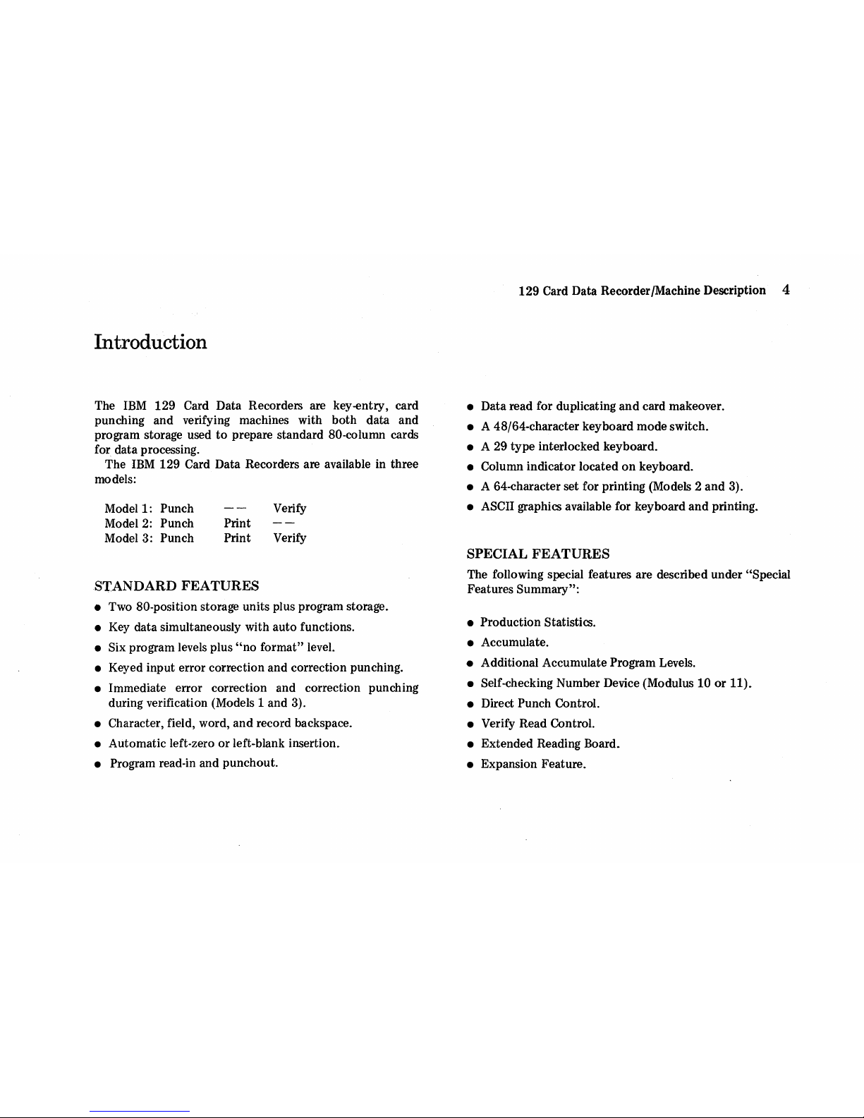
DATA
STORAGE
The
129
Card Data Recorder contains input and
output
sections
of
data storage. Each storage section can store
80
characters
or
columns
of
card information recorded in
electronic form. Data keyed for punching is
stored
(recorded) in input storage. The column indicator shows
the
input storage position where the next character
is
to
be
recorded.
If
a character
is
keyed incorrectly, the machine
can be backspaced and the correct character can
be
keyed.
Rekeying erases
the
incorrect character in input storage
and
records
the
corrected character. After a card data record
is
complete in
input
storage,
it
is transferred
to
output
storage
and
then
punched
in a card. While
the
card
is
being
punched from
output
storage, the
next
card record can be
keyed into
input
storage. (See Figure 1.)
For duplicating, data from
the
record in
output
storage
is
transferred
to
input
storage
and
becomes part
of
the input
record.
In a verify operation,
the
punched card
to
be verified
is
read into
input
storage,
and
the keyed data
is
compared
with the data read into input storage. Errors can be
corrected in input storage by a correction routine, and a
correction card can be punched immediately after comple-
tion
of
each record verification. For verify duplicating, data
in
output
storage
is
compared with data in
input
storage.
Output
Storoge
Input
Storage
---....-t
__
...1.--'--r-"_~
1.1""'--"---'
Column
Indicator
Figure 1.
Input
and
Output
Storage
}
'ooohod
00>0
Duplicating
Introduction 5
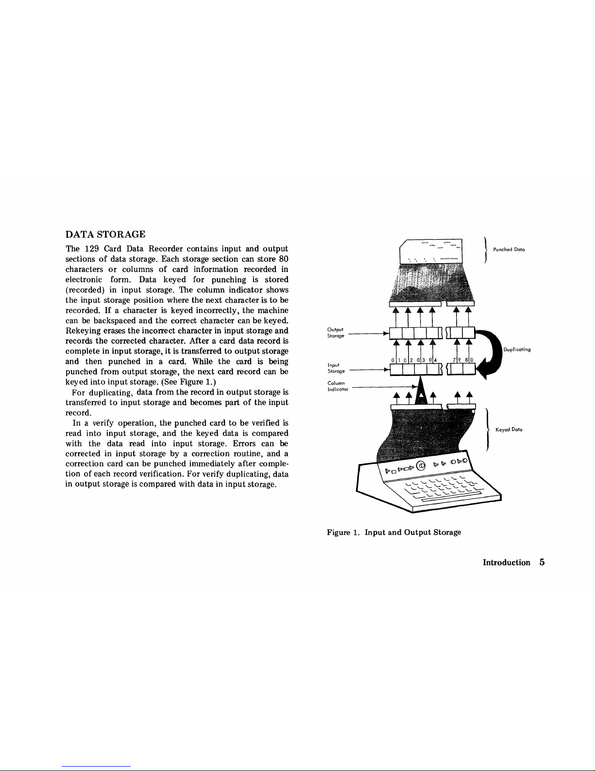
Page 7
129
Card Data Recorder/Machine Description 6
Operating Features
Figure
2.
IBM
129
Card Data Recorder Model 3 (Punch-Print-Verify)
Page 8
See Figure 2 for location
of
following components .
• COLUMN INDICATOR
The column indicator,
on
keyboard console, shows next
card column to be keyed. Refer
to
this indicator as a guide
for spacing
or
backspacing
to
a particular column.
• CARD RELEASE PUSHBUTTON
The card release pushbutton permits manual removal
of
a
card from punch/read station .
• e PUNCH/READ AND EJECT STATIONS
Models 1 and 3 (verify capability) have
a_combination
punch/read unit
at
punch station, and only a card eject
mechanism at
the
unused read location. Initial Model 2
machines have a separate
0 punch and e read station;
later Model 2 machines have the combination punch/read
station.
o CARD STACKER
•
CARD COUNT SCALE
• STACKER STOP SWITCH
The card stacker holds approximately 500 cards and has a
convenientecard
count scale. A full stacker operates
a
Gstacker
stop switch
that
interlocks
the
card feed.
However, power
is
not turned
off
and operation may
continue when cards are removed from stacker.
• CARD HOPPER
The card hopper holds approximately 500 cards. Cards are
placed in the hopper, in front
of
sliding pressure plate, face
forward, with 9-edge down.
o PRINT UNIT
The 64-character set print unit
is
only on Models 2 and 3.
e COMBINATION PUNCH/READ UNIT
•
KEYBOARD CONSOLE
The keyboard console contains operating switches and
controls.
_KEYBOARD
The keyboard contains keys for a 64-character set and for
control
of
machine. The keyboard pivots for convenience.
eCHIPBOX
The chip box
is
under the desk
top
below
the
keyboard,
and it should be emptied daily .
• MAINLINE SWITCH
The mainline switch is
on
front right-hand side
of
cabinet
under the keyboard.
When
mainline switch is turned on,
machine
is
ready for use, in program level
O.
When this
switch
is
turned off, all programs and data are reset
to
blanks.
Operating Features
7
Page 9
129 Card Data Recorder/Machine Description 8
Console Controls
PUNCH
ON
AUTO
ON
48
ON
~
C
C
C
C
C
Q
~
~
m
I
~
~~
VERIFY
OFF
MANUAL
OFF
64
OFF
~
I
~:
AUTO
CHARACTER
(I
REC/CARD
~
~~
SKIP/DUP
AD\{,
FEED
PROGRAM
MODE
PRINT
MODE
CLEAR
lI'~
I
I
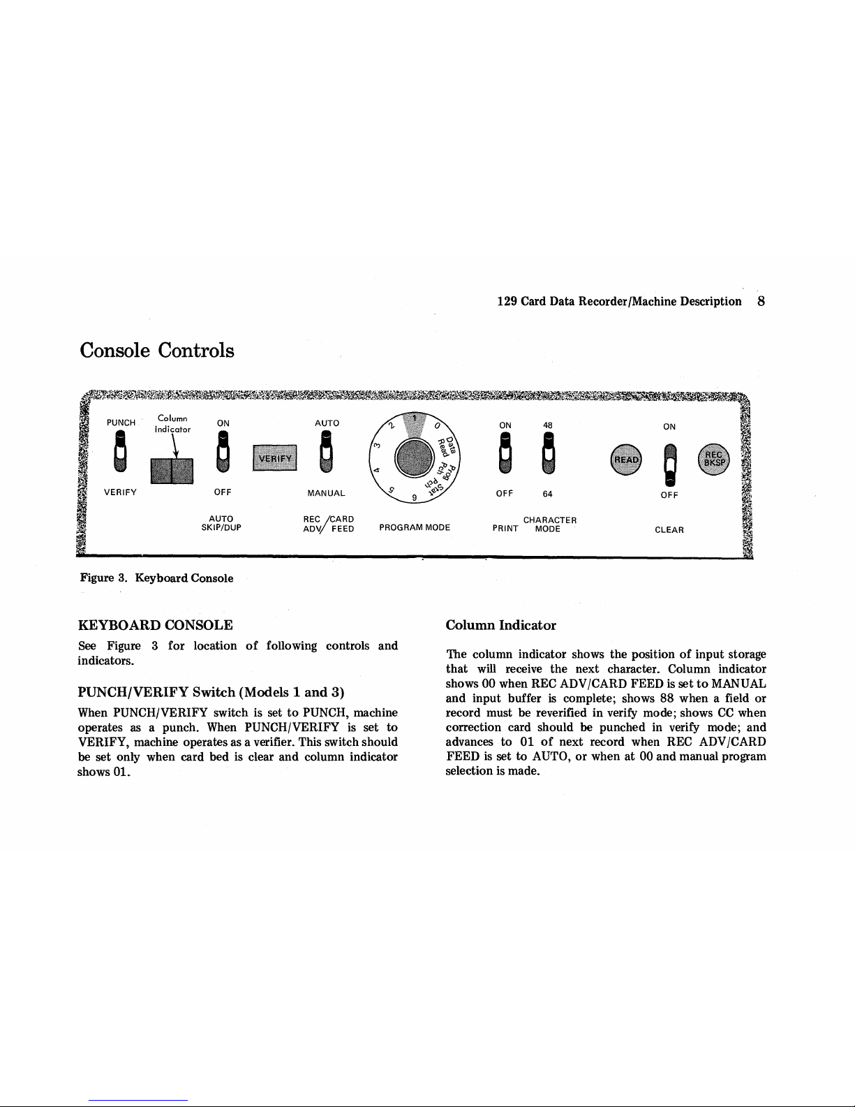
Figure
3.
Keyboard Console
KEYBOARD CONSOLE
See
Figure 3 for location
of
following controls and
indicators.
PUNCH/VERIFY Switch (Models 1
and
3)
When PUNCH/VERIFY switch is set
to
PUNCH, machine
operates as a punch. When
PUNCH/VERIFY
is
set to
VERIFY, machine operates as a verifier
..
This switch should
be set only when card bed
is
clear and column indicator
shows
01.
~
;
~
ll1
Column
Indicator
The column indicator shows the position
of
input storage
that
will receive the next character. Column indicator
shows
00 when REC ADV/CARD FEED
is
set
to
MANUAL
and input buffer
is
complete; shows 88 when a field or
record must be reverified in verify mode; shows
CC
when
correction card should
be
punched in verify mode; and
advances to
01
of
next record when REC
ADV
/CARD
FEED
is
set to AUTO,
or
when at 00 and manual program
selection
is
made.
Page 10
AUTO SKIP/DUP Switch
When AUTO SKIP/DUP
is
ON, programmed auto skip/dup
fields operate automatically at electronic speeds. Auto
duplication
of
blanks does not stop the function. When this
switch
is
OFF, fields operate as manual fields. (Switch
should
be
OFF for first record after clear operation,
or
if
data has
not been keyed or read into
output
storage.)
VERIFY
Light
VERIFY light indicates verify error
on
verify models,
and/or self-check error,
if
self-check feature
is
used.
REC ADV
(Record
Advance )/CARD
FEED
Switch
When REC ADV ICARD FEED
is
set to:
1.
AUTO, machine advances from column 80
of
one input
record
to
column 01
of
next input record, sets program
level shown on
PROGRAM
-MODE
dial, stacks present
card, and feeds next card.
2.
MANUAL, machine stops
at
column 00
of
current
record. This allows manual program selection for next
record
or
allows backspacing into present input record
for correction
of
record before card
is
punched. Press
FEED key if card feed
is
desired.
PROGRAM MODE
(Rotary
Dial)
Switch
When PROGRAM
MODE
is
set
to:
1. 0-6, program level 0-6
is
selected for next input record
(when column indicator advances from
00 to 01)
if
REC
ADV /CARD FEED
is
set
to
AUTO.
2.
DATA READ, master card data enters
output
storage
for duplication into following record.
3.
PROG PCH, data from program storage
is
punched.
4.
STAT PCH, totals for production statistics special
feature are punched.
PRINT SWitch (Models 2
and
3)
When
PRINT
is
set
to
ON
during keying into input storage,
characters
to
be printed are the same
as
those punched in
card.
All
leading
O's
are print suppressed, except for units
position
of
a field. Only 64-character set will print.
CHARACTER MODE Switch
When
CHARACTER
MODE
is
set to:
1. 64, the 64-character keyboard mode
is
selected.
2_
48, the 48-character keyboard mode
is
selected.
READ
Pushbutton
When READ
is
pressed, program/data cards are read into
storage, in conjunction with
PROGRAM
MODE
dial.
CLEAR Switch (Momentary Spring Loaded)
When
CLEAR
is
held ON, all cards move
out
of
transport
into stacker and column indicator returns
to
01. Dup will
not operate in first record following a clear operation.
REC BKSP
(Record
Backspace)
Pushbutton
When
REC
BKSP
is
pressed, column indicator returns
to
column 01
of
input storage without changing current
program level, and any auto operation (skip/dup)
pro-
grammed for column 01
is
suspended.
Console Controls
9
Page 11
129 Card Data Recorder/Machine Description
10
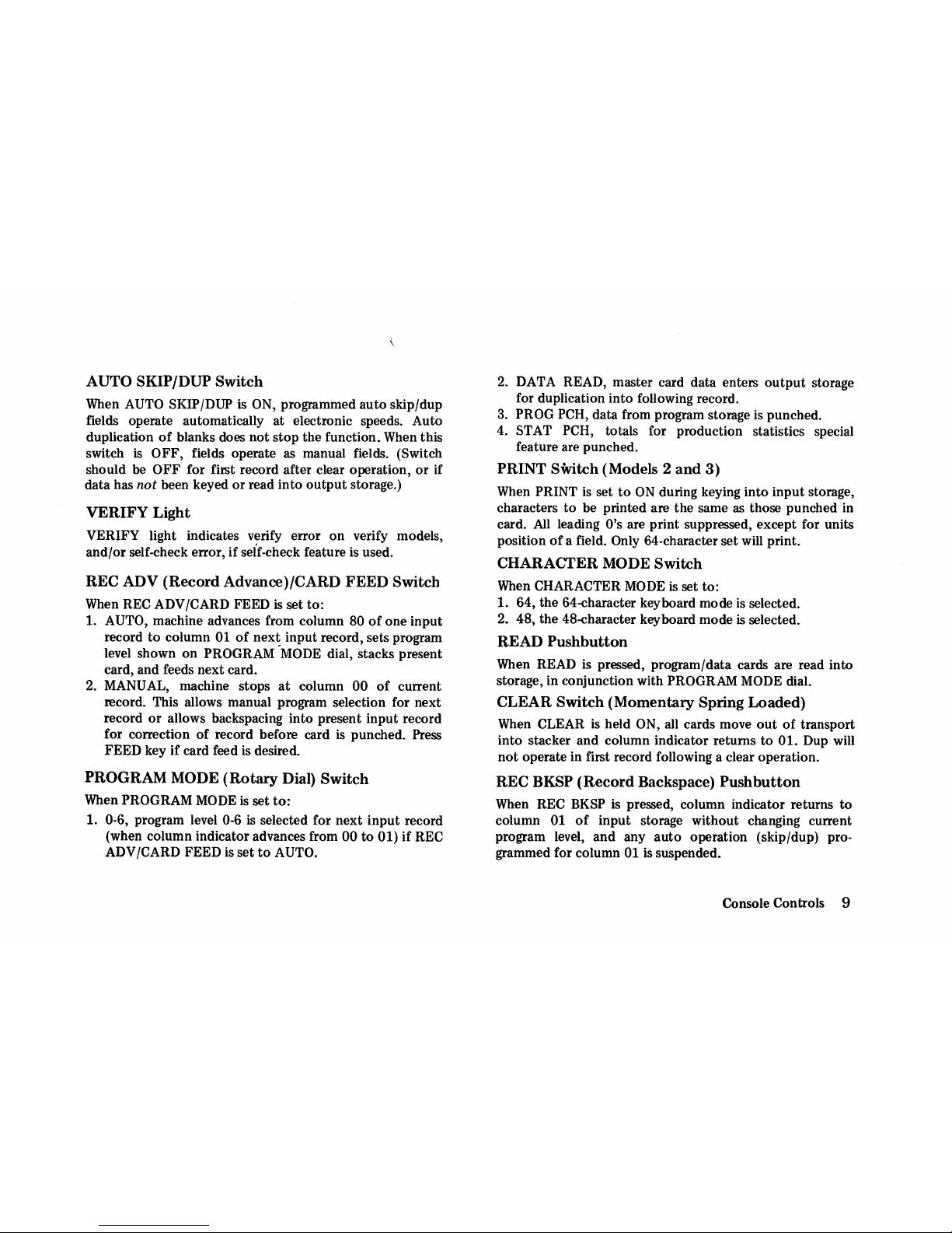
Keyboard Controls
Alternate Keys
for
Model 2
Figure
4.
Keyboard
Controls
Page 12
KEYBOARD
See Figure 4 for location
of
following keyboard controls.
FEED
(Card
Feed)
Key
Punch Mode: Holding FEED key down moves two cards
from
hopper
into register and pre-register positions
of
punch station. Key
is
inoperative when a card
is
registered
at
punch station.
Verify Mode: Feeds one card from hopper.
The
card is read
at
punch/read station. Cards
to
be verified must be fed
from hopper; they cannot
be
inserted manually.
REG
(Register) Key
If
a card
is
pre-registered
or
manually inserted, REG key
registers the card
at
punch/read station. Pressing this key
will not feed a card from hopper.
SKIP Key
Punch Mode: SKIP key initiates a skip
to
end
of
field
definition.
If
no field definition or program
is
in level 0,
this key provides a single space.
Verify Mode: Column in which SKIP key
is
pressed
is
verified
to
be blank, and a skip without following verifica-
tion to
end
of
that
field
is
initiated.
If
column is punched, a
verify error
is
signaled. In a programmed
LZ
(left-zero)
verify field,
SKIP key is operative
only
as the first
keystroke.
REL
(Release) Key
Punch Mode: REL key moves column indicator through
column
80,
and
space codes are written in input storage.
The column indicator advances
to
column
00
if REC
ADV/CARD FEED
is
set
to
MANUAL,
or
advances
to
column 01
of
next
record
if
REC ADV /CARD FEED is set
to
AUTO. Fields programmed for
auto
dup beyond
point
of
release are duplicated if AUTO SKIP/DUP is ON.
Verify Mode: With REC ADV /CARD FEED set
to
AUTO,
pressing REL key causes card
to
be released without
verification and without
OK punches in column 81, card
is
stacked, and next card
is
fed. With REC ADV /CARD FEED
set
to
MANUAL, pressing REL key moves column indicator
to
column 00
to
await
operator
action. (Use manual
program selection and
then
FEED key,
or
set REC
ADV/CARD FEED to
AUTO,
or
use CLEAR switch
to
continue verify operation.) Fields programmed for
auto
verify beyond
point
of
release are verified
if
AUTO
SKIP/DUP
switch
is
ON. Once released, a card cannot be
OK-punched in column 81 (2-3 punch) unless again fed
from the hopper and reverified.
Keyboard Controls
11
Page 13

Data
Keys (Alpha, Numeric, Special
Character, Space)
Depression
of
one
of
data keys enters a character into input
storage for punching,
or
compares
it
with input storage for
verifying. Alpha
or
numeric shift
is
determined by program
or
manual control: [The
-LZ
key has a special use for
left-zero fields; see
"BLANK COLUMNS/LEFT ZERO
CTRL (Control) Key."] The special characters in the
outlined area (Figure 4) are active only in 64-character
mode.
Note: The dash
(-)
II-punch
is
available only in
alpha shift.
PROG
SEL
(Program Select) Key
Pressing PROG SEL key followed by a data key (0-6) shifts
machine
to
program level selected. (Keyboard locks
if
other
than
0-6
is
selected.)
_Program
level selection can be made
any number
of
times during the keying
of
a record. On
advancing
to
next record, program returns to level indi-
cated by
the
setting
of
PROGRAM MODE dial,
if
REC
ADV/CARD FEED
is
set
to
AUTO.
If
REC ADV/CARD FEED
is
set
to
MANUAL (column
indicator
at
00), depression
of
PROG SEL key followed by
a data key
(0-6) selects
that
level for next
input
record,
punches and ejects present card (does
not
feed a card), and
advances column indicator
to
column 01
of
next
record,
or
to
first manual column if an auto field
is
programmed
at
start
of
record and AUTO SKIP/DUP switch
is
ON. Press
FEED key if card feed
is
desired.
129 Card Data Recorder/Machine Description
12
ALPHA
(Alphabetic
Shift) Key
Pressing ALPHA key shifts keyboard into alpha mode,
as
long as key is held down.
When
this key
is
released,
machine returns
to
shift indicated by program.
NUMERIC (Numeric Shift)
Key
Pressing NUMERIC key shifts keyboard into numeric mode,
as long
as
key
is
held down. The numeric shift key must be
held down when operating in program level
0 and numeric
keying
is required.
It
is used
to
override alpha programming
when under program control.
If
both
NUMERIC and
ALPHA shift keys are pressed, numeric shift takes precedence.
CHAR BKSP
(Character
Backspace)
Key
Each depression
of
CHAR BKSP key causes one manual
column
of
backspacing,
or
unlocks keyboard (without a
character backspace operation)
if
keyboard was locked due
to
an invalid key depression. When used after an error in
verify mode, before rewrite,
it
resets
the
error condition
and allows additional verify attempts
of
character in
question. When used
after rewrite, it allows reverification of
rewritten character.
Note: Character backspace will
not
reset a program select condition after PROG SEL key has
been pressed. Either complete
the
selection
or
use FIELD
BKSP
key
to
reset program select condition.
Page 14

FIELD/WORD BKSP (Field/Word Backspace) Key
A depression
of
FIELD BKSP key returns column indicator
to
first column
of
field being keyed.
If
in first column
of
a
field, pressing this key returns column indicator
to
start
of
previous manual field.
The FIELD
BKSP key operates as a word backspace key
when used in conjunction with
the
ALPHA shift key.
Pressing ALPHA shift key and FIELD BKSP key returns
column indicator to column following last space
that
was
spacebar entered,
or
to first column
of
a manual field,
whichever comes first. Any backspace key (character,
field/word,
or
record) may be used to unlock a locked
keyboard. Backspace does not change
the
current program
level.
MULT PCH (Multiple Punch) Key
Pressing MULT PCH key places keyboard in numeric shift
and prevents column indicator from advancing while
ihdividual codes are keyed.
If
multiple'. punch special
character
is
not
one
of
standard 64 characters, printing
is
suppressed
..
VER/DUP (Verify
or
Duplicate) Key
VER/DUP key is' used
to
duplicate
or
verify a column or
field
of
data from previous record in
output
storage. This
key
is
inoperative unless data has been keyed or read into
output
storage.
Wheri
this key
is
held down, it repeats the
function
at
a rate of 10 fields/second in program levels 1-6,
or
10
columns/second in program level
O.
Verify Mode: In a left-zero programmed field, it must be
the first key pressed in
the
field; this key
is
inactive in any
other
position
of
the
field.
BLANK COLUMNS/LEFT ZERO CTRL (Control)
Key
Punch Mode: Pressing LEFT ZERO CTRL key, after a
character
or
characters for a field are keyed, starts a
left~zero
(fill) operation if keyboard
is
in numeric shift or
starts a left-blank (fill) operation if keyboard
is
in alpha
shift. This key
is
not
operative in first position
of
any field.
Use
-LZ
key for minus over units position and start LZ
fill operation combined. For filled field (all digits, no
O's),
use "MULT P(jH (Multiple Punch) Key" procedure for
minus over units position. Maximum length
of
a single
LZ
field
is
79 positions.
Verify Mode: In any field, pressing BLANK COLUMNS key
verifies blanks until a character
or
end
of
a field
is
reached.
In
units position
of
a programmed left-zero
field~
this key
only performs left-zero control function. This key must be
pressed after verification
of
units position
of
field; other-
wise, keyboard lockup occurs.
Use
-LZ
key after units
position verification for minus over units position verify
and LZ control operation combined.
Keyboard Controls
13
Page 15

VER
CORR
(Verify Correction) Key
Verify Mode Only: Pressing VER
CaRR
key in any field
allows a rewrite
of
balance of field; pressing this key after a
record backspace operation allows rewrite
of
the complete
record. The keyboard locks (column indicator shows 88)
and field
or
record must be reverified.
At completion
of
record verify operation, if any rewrite
correction has been made by use
of
"VER
RES (Verify
Reset)
Key" procedure or
"VER
CaRR
(Verify Correc·
tion) Key" procedure, machine locks with column indicator
showing
CC.
CC
indicates
that
a correction card should be
punched. Manually insert a blank card in punch station and
press
VER
CaRR
key
to
punch
out
corrected card.
129 Card Data Recorder /Machine Description
14
VER
RES (Verify Reset) Key
Verify Mode Only: Pressing VER RES key resets a verify
error condition and allows a second verify attempt. If verify
error
is
signaled again, reset is performed and third
keystroke rewrites storage with the new character. After
rewrite, perform character backspace and reverify;
other-
wise, machine will lock at
end
of
field (column indicator
shows 88) and require field backspace and reverification.
(Character backspace may be used
to
interrupt error
routine and allow additional verify attempts before
rewrite.)
Page 16

Graphics and Card Codes
PROGRAM CARD CODES
A program card, which is a basic part
of
program control,
is
prepared for each punching application. Proper punching
in
this program card controls automatic operations for corresponding columns
of
data cards being punched or verified.
Each row
in
program card governs a specific function. (See
Figure 5.)
Function
Standard Codes
Field Definition
(FD)
Auto Skip Field
Auto Dup/Auto Ver Field
A
Ip~a
S~ift
(Programmed)
left-zero
Control Field (Verify Only)
Specie I Feature Codes
Self-c~eck
Field
Add Accumulator A
Add Accumulator B
Add Accumulator C
Punch
Accumulator
A,
B,
or
C
Punch
and
Reset
Accumulator
A,
B,
or
C
Direct Punch Control for
II
Buffered " Field
Verify Read
Cantr~1
to Stop Verify Read
Operation
Figure
5.
Program Codes
Punc~
Code Field Location
12
All
columns,
except
first column
?
11
First column
First
column
Eac~
column for
alp~a
s~ift
First
and
last
columns
First and lost columns
First column
First
column
First
column
4 +
(5
or 6
or
7)
First column
4 + B
+(5
or 6 or 7)
First
column
First
column
for
direct
punch
mode
only
11-0
Column desired to
stop
card
Notes for Figure
5:
1.
Program codes
apply
in program levels
1-6.
Program level 0
is 80 single-position fields,
alpha
shift.
2.
If
lZ
control in units position verify is not desired, do not
use
3-punch
in units position.
3.
Only
field definition is required for
lZ
punching. Program
cards coded for
lZ
in veri
fy
mode (3-punches) may
be
used in
punch mode without
alteration
because
machine ignores
3-
codes in punch mode, unless
direct
punch control feature
is
used (see
chart).
4.
Minimum field
size
is two columns for
accumulate,
self
check,
and
lZ.
5.
Maximum field
size
is
79
columns for self
check
and
lZ.
6.
Maximum
input
field
size
for
accumulate
is 14 columns;
maximum punchout field
size
is 19 columns.
7.
A field may
be
programmed to add
into
any
or
all
accum-
ulators; punchout is limited to
one
accumulator per
field.
8.
Self-check
fields may
be
adjacent.
Self
check
and
accumulate
operate
in both punch and verify mode. However,
self
check
cannot
be
programmed in
the
same field
as
accumulate
or
left
9.
Verify read control (11-0 code)
must.
not
be
programmed in
same
column
as
auto
skip (11)
or
auto
dup
(O)
codes,
nor in
any
self-check
programmed
field.
10. Programs remain in storage until
another
program is read
;n
to
replace
the
original program, or until mainline switch is
turned
off,
which resets programs
1-6
to blanks (equivalent
to 80 single-position fields, numeric
shift).
Graphics and
Card
Codes
15
Page 17

129 Card Data Recorder/Machine Description
16
CARD
VISIBILITY AND PRINTING
64-character Mode
48-character Mode
~
__________________________
A~
________________________
~~
11
speciais
16
Additional
Specials
(No
Graphic
for
0-8-2)
Note
1
III
<;(+1
!);..,
1111
111111111
: III
1111
I
00000000000000000000000001111111100000000001110000000000000
1113
14
15
1~
17
lB
19
1011
11131415
1617
lB
19
30
31
3133343536
37
3B
39
40
41
414J
44
45
46
47
46
49
50
51
5153
54 55 56
57
58 59
60
61
626364656661686910
111111111111111111111111111111111111111111111111111111111111
2 2 2 2 2 2 2 212 222 2 2 2 212 2
22
2 2 212 2 2 2 2 2 222 2 2 2 2 222 2 2 2 2 2 222 212 2 212 2 2
333333333133333333133333331333333333331331331313333333333333
4 4 4 ~ 4 4 4 4 4 414 4 4 4 4 4 4 414 4 4 4 4 4 414 4 4 4 4 4 4 4 4 4 4 14 4
14
4 14
14
4 4 4 4 4 4 4 4 4 4 4
555555555551555555551555555515555555555555555555555515551555
666666666666166666666166666661666666666666666666666661666166
7777777777
7 7177
77 77
7717 7 7 7 7 7
717 7 77
7 7 7 7 7
77 7 77 7 77
77 77 7 717
7717
818BB8BB8B888BI8BBBBBBBIB8BBB881BBBB8BIIBIIBIII18B8111
11111
991999999999999199999999199999991999999999999999999999999999
13
1415
i617
181~
lull
22
2124
2~
2627 2829
303132133435.1£1
37
3839
'Q41
42
4?444S464148 4950:;152535455565158
S96061
SZFJS465
6667686910]1
Nonvisual
Columns
Model 2
(Initial
Shipments)
Note
1
•••••
tLZ~/,'~Z~d
Models 1 and 3 (Punch); Model 2 (Punch)
with
serial
No.
2xxxx.
Depending on
operator
position,
columns 10-11 are visible also.
1.
Maximum
possible
visibility
is
columns 8-80
in
punch mode
and
columns 1-77 in
verify
mode.
but
operator
position
may
not
be convenient.
2. A pre-registered card in punch mode has
columns 1-80 visible,
but
requires manual
operator
control
of
punching and feeding
operations.
f\\SlS\' Models 1 and 3
(Verify).
Depending on
operator
position,
columns
72·74
are visible also.
3.
Direct
punch
control
feature and
verify
read
control
feature
provide
additional
visibility
for
source
document
keying.
See
"Special Features
Summary."
Figure 6. Card Visibility
Page 18

DATA CARD CODES AND GRAPHICS
Figure 7 shows key top graphics
of
64-character set and
related card codes for character set
"EL."
Alpha Shift
Numeric Shift
Graphic Card Code Graphic Card Code
A
12-1
0 0
B 12-2
1
1
C 12-3
2 2
D 12-4
3 3
E 12-5
4
4
F 12-6
5 5
G 12-7
6
6
H 12-8
7 7
I
12-9
8
8
J 11-1 9 9
K 11-2
L
11-3
~
12-8-2 t
M
11-4
12-8-3
N 11-5 (
12-8-5 t
0 11-6 + 12-8-6 t
P
11-7
I
12-8-7 t
Q
11-8
! 11-8-2 t
F 11-9
$
11-8-3
S
0-2
)
11-8-5 t
T
0-3
;
11-8-6 t
U
0-4
I
11-8-7 t
V
0-5
W
0-6
0-8-2
0-8-2
t
(key top only)
X
0-7
0-8-3
Y
0-8
-
0-8-5
t
Z
0-9
>
0-8-6
t
/
0-1
?
0-8-7
t
12-8-3
8-2
t
<
12-8-4
#
8-3
*
11-8-4
8-5
t
0-8-3
=
8-6
t
%
0-8-4
8-7
t
@
8-4
&
12
-
11
Figure
7.
Card
Codes
and
Graphics
Notes
for
Figure
7:
1.
Dagger
denotes
16
additional
special
characters
that
are
only
in
64-character
set.
2. ASCII
graphics
are
the same as
the
64-character
set,
except:
12-8-2
is [
11-8-2
is]
0-8-2
is
\
3.
Squared
alphabetic
letter
0 is
standard,
to distinguish
it
from numeric
O.
4.
The
11-0
combination
(minus
over
0) will
not
print.
The 11-1 through 11-9 (minus
over
digit)
will
print
letters
J-R.
5.
Space
is a
blank
column in both
alpha
and
numeric
shift.
6.
Dash
(-)
ll-punch
is
available
only
in
olpha
shift.
Graphics and Card Codes 1 7
Page 19

Operating Procedures
POWER ON
Setting
the
mainline switch
to
ON
resets (erases) all stored
programs and data, and selects program level
0 regardless
of
PROGRAM
MODE
dial setting.
Program level 0 control is
80
single-position fields (alpha
shift).
Program levels 1-6,
at
this time, are controlled
as
80
single-position fields (numeric shift). Program selection
is
possible, although program levels 1-6 are identical, until
programs are read into program storage.
Punching and verifying can be done under program level 0
or
1-6 control. However,
the
first operation normally
performed, after power is turned on, is
to
store the
programs desired in program levels 1-6.
New program cards may be punched before programs are
loaded by using
the
"Punch a Card" procedure.
STORE A PROGRAM (Program Load)
The desired program cards must be read into program
storage
to
allow program control
to
be active during
keying:
1. Operate CLEAR switch if card bed
is
not
clear.
2.
Set AUTO SKIP/DUP
to
OFF.
129 Card Data Recorder/Machine Description
18
3. Set PROGRAM
MODE
to
desired program level (1-6).
4. Insert program card at punch/read station (punch or
verify mode),
or
feed card one cycle from
the
hopper
to
the pre-register position (punch mode). Card must not
be registered.
5.
Press READ pushbutton.
Repeat steps
3-5
for each program card
to
be stored. Each
program load operation reads program card data into
selected program storage level, stacks card in stacker, and
sets machine
to
column 01
of
that
program level. Programs
remain in storage until a new program
is
read into that
program level
or
until a power off/on operation resets
them.
Note: In punch mode, up
to
six program cards may be
placed in hopper, fed singly, and program loaded
by
repeating steps· 3-5. Then set PROGRAM
MODE
dial,
manually select desired program level, and set
PUNCH/
VERIFY switch
to
PUNCH
or
VERIFY
to
start operation.
Page 20

PUNCH OUT A PROGRAM
To check
that
a particular program has been stored
at
a
specified level, punch
out
the
program on a blank card:
1. Operate CLEAR switch
if
card bed is
not
clear.
2.
Set PUNCH/VERIFY switch
to
PUNCH.
3. Set AUTO SKIP/DUP
to
OFF.
4.
Set REC
ADV
/CARD FEED
to
MANUAL.
5. Set PROGRAM
MODE
to
PROG
PCH.
6. Insert blank card at punch station,
or
feed blank card
from hopper.
7. Press REG (registers a card).
8. Press REL (sets column indicator
at
00).
9. Press PROG SEL followed by data key (1-6) for
program level desired.
Punch out follows and card
is ejected.
If
data key 0
is
pressed after PROG SEL, a blank card results. Repeat steps
6·9 for each program to be punched out.
All
program cards are automatically printed (Models 2
and 3) during program punchout operation regardless
of
PRINT switch setting. Program punchout may be done
at
any time. Machine
is
set
to
that
program level
at
conclusion
of
program punchout.
PUNCH A CARD
This procedure applies for punching data cards
or
for
punching program cards (before a program has been
loaded), using either program level
0
or
program levels 1-6.
When programs have been read into storage, card
punching can begin under program format control:
1. Place blank cards in hopper.
2.
Operate CLEAR switch
if
card bed is not clear.
3. Set
PUNCH/VERIFY switch
to
PUNCH.
4. Set AUTO SKIP/DUP
to
OFF.
5.
Set REC
ADV
/CARD FEED
to
AUTO.
6.
Set PRINT
to
ON/OFF, as desired.
7. Set CHARACTER
MODE
to 48/64, as desired.
8. Press FEED key (feeds two cards).
9. Set PROGRAM
MODE
to
desired program level (1-6 or
0). Manually select desired program level by pre$ing
PROG SEL followed
by
data key 1-6
or
0 (first record
only).
10. Key first card record manually. Duplicating
is
not
active and skipping
is
under manual control for first
card. After first record
lias been keyed:
11. Set
AUTO SKIP/DUP
to
ON.
On following records, programmed duplicating and
skipping are performed automatically, and program level
selection at start
of
each record is automatic, under control
of
PROGRAM
MODE
dial. Any field programmed for
manual entry may be manually keyed, duplicated from last
record,
or
skipped by manual operation.
If
an
error
is
made
in keying, a backspace-rewrite operation
is
required.
Operating Procedures
19
Page 21

READ DATA
During this operation, a data card
is
read into
output
storage,
to
be used for new
"master"
card data for
duplication into
the
following record:
1. Operate CLEAR switch if card bed
is
not
clear.
2. Set
PROGRAM
MODE
to
DATA READ.
3. Insert data card
at
punch/read station (punch
or
verify
mode),
or
feed card one cycle from hopper
to
pre-
register position (punch mode). Card must not be
registered.
4. Press READ pushbutton.
The machine
is
automatically set
to
program level 0
(alpha shift) and card
is
stacked. Continue desired operation after setting PROGRAM MODE dial, and manually
selecting proper program level. Data from the data read
operation cannot be punched
out
from
output
storage,
except by duplication into following record.
VERIFY A CARD
Verify. procedures are normally performed under program
control:
1. Place cards to
be verified in card hopper.
2.
Operate CLEAR switch
if
card bed
is
not
clear.
3. Set PUNCH/VERIFY switch
to
VERIFY.
4. Set AUTO SKIP/DUP
to
OFF.
129 Card Data Recorder/Machine Description
20
5. Set REC ADV /CARD FEED to AUTO.
6. Set PRINT
to
ON/OFF (affects correction punched
cards only).
7. Set CHARACTER
MODE
to 48/64, as desired.
8. Press FEED key (feeds
one
card). The first card
is
read
and stored in input storage.
9. Set
PROGRAM
MODE
to
desired program level (1-6 or
0). Manually select desired program level by pressing
PROG SEL followed
by
data key 1-6
or
0 (first record
only).
Begin verify operation by keying first record from source
document. Duplicating
is
not
active and skipping
is
under
manual control for
the
first verify record. After first record
has been verified:
10.
Set AUTO SKIPjDUP
to
ON.
On
following records, programmed verify duplicating and
skipping are
perfo~ed
automatically, and program level
selection at start
of
each record
is
automatic, under control
of
PROGRAM
MODE
dial.
At
completion
of
keying,
if
no
errors exist, a 2· and a
3-punch are punched in column 81
of
original card to
signify an
OK verify without errors.
If
column indicator
shows 88, a field (or record) must be reverified.
If
column
indicator shows
CC,
a correction card should be punched.
Refer
to
"VER
RES (Verify Reset) Key" and
"VER
CORR
(Verify Correction) Key" descriptions under "Keyboard
Controls"
for error correction routines.
Page 22

PUNCH A
VERIFY
CORRECfION
CARD
This procedure
is
used during verify mode operation
to
punch a verify correction card after a verify record has been
corrected in input storage. The column indicator shows
CC
for card correction:
1.
Insert blank card at punch station. Card must
not
be
registered.
2. Press VER CORR.
The card is registered
and
punched with corrected data.
Only a 2-punch is punched in column 81
to
signify
that
a
correction was made during verify operation. The error card
has no punches in column 81 and may be discarded. The
following card
is
fed and read; verification continues.
Note:
If
correction card punching
is
not
desired, use FEED
or
CLEAR,
find
continue verify operation. The FEED key
allows manual
or
auto dup in following record. The CLEAR
key prevents dup in following record. The error card
is
stacked with no punches in column 81.
Once a rewrite has been done in verify mode or record
has been released, column 81
is
not punched in original
card.
If
it
is
desired
to
have column 81 punched (because
of
verify operator error, and card
is
correct as originally
punched), card must be inserted in hopper, fed, and then
verified without error.
ADD A PUNCH
To add a punch
to
an existing punched card, because
repunching (makeover)
of
original card
is
not desirable,
proceed as follows:
1.
Operate CLEAR switch if card bed
is
not
clear.
2. Set
AUTO SKIP/DUP
to
OFF.
3.
Set REC ADV/CARD FEED
to
MANUAL.
4. Set PRINT to ON/OFF,
as
desired.
5.
Space or manually skip in input storage to desired
column.
6.
Key
only added character
or
characters.
Use
manual
alpha or numeric shift if shift
of
program level
is
not
known.
7. Press REL (column indicator advances
to
00).
8. Register the existing punched card at punch station.
9. Set REC ADV/CARD FEED
to
AUTO.
The punched card will be "overpunched" with spaces in
all columns, and desired added punch( es) will
be
punched
in column(s) in which it was keyed.
An
alternate procedure would be
to
data read a blank
card, manually dup
to
desired column, key the data,
release, and proceed
to
step 8.
Operating Procedures 21
Page 23

REPUNCH (MAKE OVER) A CARD
Repunching a card
that
must be altered
or
corrected by
changing existing punches is done as follows:
1.
Perform
"Read
Data"
procedure with
the
punched card.
(machine is automatically in program level
0, alpha
shift.)
2. Set REC ADV/CARD FEED
to
AUTO.
3. Set PRINT
to
ON/OFF, as desired.
4. Manually
dup
up
to
column(s) requiring a change
or
correction, key
the
correction,
then
manually dup
balance
of
the
card.
5. Register a blank card
at
punch
station,
and
card is
then
punched with original
and
corrected data.
REPLACE THE RIBBON (MODELS 2 AND 3)
The print ribbon feeds between
eo
two
spools, through
G)
4D
ribbon guides, and under e punch/read station, as
shown in Figure 8. The old ribbon
is
removed and a new
one
is
installed
as
follows:
1. Turn
off
mainline switch. (Note: Punch
out
any
production statistics
or
accumulate total(s) informa-
tion before
you
turn
power
off
because power
off
condition resets all totals to 0 and all programs and
data to blanks.
129 Card Data Recorder /Machine Description
22
2.
Remove cover over print-feed unit.
3. Remove
G ribbon-spool retaining clamp.
4. Cut or break
the
old 8 ribbon, then remove both
eo
spools from their G spindles and pull
out
the
two pieces
of
ribbon.
Empty
one
of
the
spools.
5.
Place spool
of
new ribbon
on
G right-hand spindle;
position spool so
that
ribbon feeds from
top
of
spool
toward the front
of
the
machine. Lift up right end
ofe
ribbon-reversing arm,
if
it
is
not
already up, and
unroll
about
18
inches
of
ribbon; then push down right
end
of
ribbon-reversing arm
to
hold spool steady.
6. Feed metal leading-end
of
the ribbon between
CD
punch/read station and card bed, sliding it through
groove in center
of
0 card bed (between the 3 and 4
punching positions). The groove permits the extra
thickness
of
the
metal end and
the
G reversing eyelet
to
pass between punch die and card bed.
Be
sure to
keep ribbon straight, with
top
side up
at
all times.
7. Hook metal leading-end
of
ribbon in slot in center
of
empty
spool and wind ribbon
onto
spool until
G reversing eyelet
is
on
spool.
8.
Place spool
on
left spindle; position it so
that
ribbon
feeds
onto
spool over
the
top.
Be
sure
that
ribbon
is
not
twisted
and
that
top
side
of
ribbon
is
still up.
Page 24

9. Hook ribbon around G) right and
CD
left wire 'ribbon
guides, and slide it through right and left ends
of
0 reversing arm and over
the
e right and . left
rollers in front
of
the
ribbon spools.
10. Slioe ribbon up under punch /read station so
that
it
is
in G upper groove provided for it in
the
card-
printing position (above
the
12 punching position), and
take up the slack.
11. Replace
Gribb
on-spool ret&ining clamp.
12. Replace cover on
print
-feed unit.
13. Turn mainline
sWitch on; machine operation can be
resumed .
Figure
8.
Ribbon Replacement
Operating Procedures 23
Page 25

REMOVE A CARD JAM
The
IBM
129 uses "fiber optics" in the read mechanism
to
provide high reliability and quiet operation. Card jams can
normally be removed by pressing card release pushbutton
and by pulling jammed card gently, or by pushing pieces of
jammed card with another card.
Try
to
assemble jammed·card pieces together
to
be sure
that all pieces have been removed and
to
facilitate
makeover
of
the card.
If
all
pieces cannot be removed, try
the following procedure in punch mode:
1. Set PRINT and
AUTO SKIPjDUP
to
OFF.
2.
Set REC
ADV
JCARD
FEED
to
MANUAL.
3.
R~move
any loose cards from
card
bed.
4. Manually select program
O.
(Keyboard
is
in alpha shift.)
5. Key
in all 80 columns, with &,
-,
and digits 0-9,
sequentially.
6. Manually insert a card
at
punch station.
7. Press REG.
8. Press card release pushbutton;
hold
it down through
step 9.
9. Manually select program
O.
(Press PROG SEL, then
data key 0.) Punchout follows; however,
the
card does
not move while you press card release pushbutton.
10. Tear a strip
of
card about 1-inch wide and use
it
(or the
special
"type
129 card saw")
to
push
out
pieces
of
card
which may still be under the punch.
11.
Repe~t
this entire procedure, using
DUP
key for step 5.
Do
the
procedure several times if pieces
of
card are still
jammed.
129 Card Data Recorder /Machine Description
24
Note:
If
card
saw
must be used, be sure
to
use only the
special
"type
129 card saw"
that
is
included with every
machine.
CARD INFORMATION
1. Cards with upper left or upper right corner cuts are
acceptable although printing may be affected by size
of
cut.
2. Cards with lower corner cuts (except lower left corner
cut
C-3,
30-degree, 0.130-inch base measurement)
cannot be fed.
3.
Round corner cards are acceptable.
ACOUSTIC COVER
An acoustic cover for the card transport
of
the
IBM
129
is
available
to
provide further noise reduction, in addition
to
that
resulting from the use
of
fiber optics sensing, electronic storage, and sound-reduced mechanical components.
The cover
is
similar
to
the acoustic cover for the
IBM
29/59 macbine; it may be field installed.
KEYBOARD LOCKUP RECOVERY
The
IBM
129 has several machine and keyboard interlocks
to
prevent invalid
or
erroneous operation,
to
detect
potential errors, and
to
ensure accurate data during punch
or verify operations. Recovery procedures are:
Page 26

Punch
or
Verify Mode
Invalid character key.
Attempted duplication after
CLEAR.
Invalid program selection.
Hopper
out
of cards.
Stacker full.
Column indicator at
00,
and
REC
ADV
/CARD
FEED set
to
MANUAL.
Punch Mode Only
Attempt
to
key when in-
put storage
is
full (may
occur on records that have
a small number of manual
columns and remainder
is
auto skip or auto dup
columns).
Character backspace and
rekey.
Character backspace and
manually key in data.
Character backspace and
select program levels
0-6.
Add cards and feed.
Remove cards and continue.
Set REC ADV/CARD
FEED
to
AUTO, or manually select program and feed
a card.
Character backspace and
continue after data in input
storage has been transferred
to output storage.
Verify Mode
Only
Compare error; VERIFY
light
ON.
Attempt
to
verify before
first manual column has been
read by machine. Keyboard
will
not accept keystroke.
Left-zero control error in
units position
of
left-zero
programmed field.
Failure
to
reverify a correction (column indicator
at 88).
Use
VER RES and retry
and/or correct.
Key only when first manual
column has been read by
machine.
Check for correct number of
leading
O's
in field; reverify
or correct as required.
Field or record backspace
and reverify.
If
the preceding recovery procedures do
not
correct the
lockup,
use
CLEAR and restart
the
operation, being sure
to
check switch settings and
to
follow the standard operating
procedures. Check
the
program being used,
via
a program
punchout operation,
to
be sure all programmed operations
are valid.
If
special features are involved, check for correct
programming
and keying procedures.
If
lockup continues,
ask your supervisor for assistance.
Operating Procedures 25
Page 27

Special
Features
Summary
The following special features are available for the
IBM
129
Card Data Recorder.
PRODUCfION
STATISTICS
The production statistics feature provides statistics
on
card
punch/verifier production for use in measurement
of
work
load, analysis
of
errors,
and
job accounting. This feature
provides a combination electronic counter package.
Keystroke
Counter
This six-position counter (000,000
to
999,999) counts
every data keystroke in punch and verify mode, and
all
functional keystrokes except: alpha, numeric, multipunch,
feed, register, program select, dup, verify correction, and
verify
reset.
It
does
not
decrement; overflow rolls from
999,999
to
000,000.
Card
Counter
This four-position counter (0000
to
9999) counts every
output
record in punch mode and every verify correct or
correction punched card in verify mode.
It
does
not
count
error cards in verify mode, program cards read in, and data
cards read in.
It
counts program cards
or
accumulator total
cards
that
are punched out. The counter does
not
decre-
ment; overflow rolls from 9999
to
0000.
129 Card Data Recorder /Machine Description 26
Verify Correction Keystroke
Counter
This four-position counter (0000
to
9999) counts each
verify correction rewrite keystroke in verify mode.
It
does
not decrement; overflow rolls from 9999
to
0000.
Operation
All
counting
is
done automatically under machine control,
not
under operator or program control.
All
counters may
be punched out,
or
punched
out
and reset, under operator-
keyboard control. Selective counter punchout
is
not
possible. Indicative data (operator number, machine number,
date, job, etc.) may be manually punched in columns 1-66
of
the total card. These keystrokes are counted in key-
stroke counter,
but
total card
is
not
counted in card
counter.
Totals may be punched by batch, job,
or
day, etc.
All
counters are reset
to
0 when machine power
is
turned off.
This feature may be field installed.
Note: In verify mode, error cards, which are
not
counted in
card counter, may be collected and counted separately and
the
number punched with other indicative data
in
the total
card
to
provide additional data on errors per card, etc.
Page 28

Punchout
Procedure
Production statistics totals are punched in columns 67-80,
under control
of
PROGRAM
MODE
and REL. Punch
out
is
done by the operator
as
follows:
1. Set machine to punch mode. Set PRINT switch
to
ON,
if desired.
2. Register a card; set REC ADV/CARD FEED switch
to
AUTO.
3.
Key
indicative information, as desired, in columns 1-66,
using any desired program level (0-6).
4. In column 67,
or
prior:
a. Set PROGRAM
MODE
to
STAT
PCH.
b.
Press REL
to
cause punchout
without
reset
of
statistics counters.
c.
Press and hold NUMERIC shift and press REL
to
cause punchout
with
reset
of
statistics counters.
5.
If
a keystroke, other than REL,
is
mad~
in column 67,
production statistics will
not
be punched
out
when REL
is
pressed (although card will be punched with indicative
data)
unle~
appropriate backspace recovery
to
column
67 or prior
is
made before REL
is
pressed.
6. Punchout occurs as follows:
Card
Columns
1-66
67-72
73-76
77-80
Information
Punched
Indicative
data
or
spaces
Keystroke
counter
total
Card
counter
total
Verify correction rewrite keystroke
total.
7. Machine
is
in program level 0
at
conclusion
of
punchout.
Set PROGRAM
MODE
to
desired home position, and
manually select desired program level
to
continue
operation.
Special Features Summary
27
Page 29

ACCUMULATE (Requires Expansion
Feature
as
Prerequisite)
The accumulate feature provides the ability
to
balance
to
a
predetermined total,
to
create a hash total for a group of
cards or a batch
of
work,
or
to
crossfoot and punch totals
in the same card or. in a following card, under program
control.
Accumulate consists
of
three 14-position, individual
accumulators
that
add any numeric manually keyed or
duplicated fields, in punch
or
verify mode, into any
accumulator, under program control. The maximum size
of
the input field
is
14 positions, and any total beyond the
14th position will carry into the 15th position, and will
maintain a valid total up to 19 positions. A minus
accumulate condition occurs if an 11-punch
is
multi-
129 Card Data Recorder/Machine Description
28
punched in units position. Amounts
to
be accumulated in
punching can be entered only by keying
or
duplicating, not
by a data read operation.
Operation
Accumulate arithmetic occurs only after entire record has
been keyed; therefore, there are
no
restrictions
on
the use
of any backspace functions during keying. Any field can be
programmed
to
add into any or all accumulators.
In verify mode, only verified correct data is accumulated,
and total fields are automatically verified for accuracy. An
error in an automatically verified
total
field
is
indicated by
AC
on
column indicator. The correction card
that
is
punched will contain the correct totals based
on
all verified
data.
Page 30

Program control
of
the accumulator uses the 4-, 5-,6-,
7-,
8-punches
of
the program card; accumulate control is active
only
ir..
program levels 1 and 2 unless the "additional
accumulate program levels" feature is also installed, which
expands accumulate control
to
program levels 3-4-5-6.
Punchout, or punchout and reset, of individual accumula-
tors are under program control, and may be done
selec-
tively.
An
accumulator can be programmed
to
punch out
into any field or fields, if desired. Only one accumulator
can punch
at
a time in any field. Group totals are normally
punched
out
via
a different program level than the
accumulating program level. Maximum punchout field size
is
19 positions. Credit totals are punched with an II-punch
over the units position.
In verify mode, a field programmed for auto skip and
accumulate
(II-punch and 5-or 6-or 7-punch) will
automatically accumulate from the card.
Minimum field size
is
two positions. Accumulate and self
check cannot be programmed in the same field.
All
accumulators are reset
to
0 when machine power
is
turned
off. (Not recommended for field installation.)
ADDITIONAL ACCUMULATE PROGRAM
LEVELS
The accumulate feature is active only in program levels 1
and 2. The additional program levels feature provides the
ability
to
program accumulate functions in program levels
3-4-5-6.
Accumulate is a prerequisite for "Additional Accumulate
Program Levels." Additional levels may be field installed.
Special Features Summary
29
Page 31

SELF-CHECKING NUMBER DEVICE
(MODULUS
10
OR
MODULUS
11)-Requires
Expansion
Feature
as Prerequisite
A self-checking number consists
of
two
parts: basic
identifying number and its check digit. The check digit,
derived from basic identifying number by a calculating
technique, is always
the
units digit
of
the self-checking
number. This feature assures
that
all digits
of
a number,
such as
an
account
or
a part number, have been correctly
keyed. Fields containing self-checking numbers can be any
size up
to
79 columns, including the check digit. More than
one self-check field can be checked per card,
and
the fields
may be adjacent.
An 11-punch is punched
in
column
81
of
the card
to
signify a valid self-checking number.
Modulus
10
Modulus
10
is designed
to
detect
the
incorrect keying
of
a
single digit or a single transposition.
It
uses weighting
factors 1, 2,
1,
2, which are automatically entered and
calculated under machine control.
Modulus
11
Modulus 11 is designed
to
detect the incorrect keying
of
a
single digit, a single transposition, and a double transposition.
It
uses weighting factors
of
7,
6,5,
4, 3, 2, which are
automatically entered
and
calculated under machine
control.
129 Card Data Recorder/Machine Description
30
Operation
The self-check field is programmed with a 2-punch in
both
the high- and low-order field positions in addition
to
normal field definition. No other program codes are
needed. Self-checking device operates in all six program
levels.
Checking
can
be
done
in
verify mode
by
manual
keying or
it
can
be
done automatically
if
the cards were
punched on a machine without the self-checking device.
Program the field for auto skip and self check (11-punch
and 2-punch), and
the
self-check calculation will occur
automatically.
Error procedures allow
the
operator
to
rekey a field
if
the
self-check number does
not
check, or
to
overpunch the
field
to
indicate an invalid number,
or
to
skip
the
field and
leave it blank.
On Model 2 machines, a "SELF CHECK"
indicator light
is
provided for error indication. On Model 1
and 3 machines, dual use
is
made
of
the VERIFY light for
both verify and
self-cJ..eck
error indication.
The high-order portion
of
a self-check field may be
automatically duplicated, and the remainder
of
the field
may be automatically skipped.
Self-checking numbers
of
Modulus 10 are
not
compatible
with those
of
Modulus 11. Self-check number generation,
self-check punch elimination, and left-based numbers are
not
available for Modulus 10
or
11. Self check cannot be
programmed in the same field as left zero (LZ), nor in the
same field as accumUlate. (Not recommended for field
installation. )
Page 32

DIRECT PUNCH CONTROL
The direct punch control feature
is
available only on
machines having serial number 2xxxx and higher.
On Model 1 and 3 machines, the PUNCH/VERIFY switch
is
expanded
to
a three-position switch with center position
being
"DIRECT PUNCH" position. On Model 2 machines, a
switch
is
added
to
allow selection
of
punch
or
direct punch
operation. When machine
is
in direct punch mode, each
keystroke
is
punched directly into
the
card, and keying and
card motion are synchronized.
All
program levels and
functions are active in direct punch mode, except left zero
and record backspace.
Direct punch
is
useful for source document punching
jobs, where card design requires card motion similar
to
the
29 for full visibility during punching; it is also used for 29
simulation by untrained users and for card makeover
or
corrections, etc.
Operation
By
program card control, individual fields may be keyed in
a
"buffered" mode, while balance
of
card
is
keyed in direct
punch mode. A 3-punch in first column
of
a field in direct
punch mode causes
that
field
to
be "buffered" and left zero
may therefore be used, and character backspace may be
used for error
correction.lIowever, a backspace beyond the
last column punched in the card
is
not
possible. Adjacent
fields may be programmed for
"buffer"
operation.
Punching
of
the"buffered" field occurs when next direct
punch column
is
punched.
Fields programmed for accumulate
or
self check will be
automatically
"buffered" in direct punch mode, regardless
of
programming. Production statistics counters count
normally when direct punch
is
used. When column 35
is
to
be
punched, columns 1-28 may be seen
on
left side
of
punch/read station,
or
columns 43-80 may be seen
on
right
side
of
station, depending on operator position
at
key-
board.
The CLEAR switch
is
not
operative for a card in direct
punch mode. Do
not
perform program load, data read,
program punchout,
or
production statistics punchout procedures in direct punch mode. This feature operates only in
punch mode; it may be field installed.
Special Features Summary
31
Page 33

VERIFY
READ CONTROL
The verify read control feature
is
available only on Model 1
and 3 machines having serial number 2xxxx or higher.
It
is
not
available on Model 2 machines.
This feature facilitates operator reading
of
source docu-
ment cards during verification, and allows verification
of
a
source document similar
to
the
IBM
59 procedure, without
the need for card format redesign.
Operation
This feature operates only under program control. An 11-0
punch in the program card, in any desired column, will stop
the machine from reading a card in verify mode, on the
column in which the
11-0
is
coded, before
that
column has
been read for verification. (The column indicator shows the
next column
to
be verified, regardless
of
the card position
in the bed.)
If
the card
is
stopped on column 35, by an 11-0 punch in
column 35
of
the program card, then columns 1-28 may be
seen on the left side
of
the punch/read station,
or
columns
43-80 may be seen on the right side
of
the station,
depending
on
operator position at keyboard. When column
prior
to
the 11-0 code has been verified (column 34 in this
case), reading again starts until the next
11-0
is
read in the
program.
129 Card Data Recorder/Machine Description
32
All
functions and operations remain the same when verify
read control feature
is
used. Accumulate, self-check, and
production statistics operate normally. The CLEAR switch
is
not
operative until column 80 has been read for any card
in which verify read control
is
used. [Note: Do
not
use 11-0
in column 1, nor in any column in which auto skip (11) or
auto ver-dup
(0)
is
programmed, nor in any self-check
programmed field.] This feature operates only
in
verify
mode; it may be field installed.
EXTENDED READING BOARD
The working area
of
the reading board may
be
increased by
adding an extension measuring
11-1/2" x
12",
to
the
front
edge, left side
of
the standard reading board. This may be
field installed.
EXPANSION FEATURE
The expansion feature does
not
provide a function
by
itself,
but
it
is
necessary
to
provide additional capacity in the
machine
to
allow the installation
of
accumulate
or
self
check.
Only one feature
is
needed, whether accumulate or
self check
or
both are installed. (Not recommended for
field installation.)
Page 34

Index
accumulate
feature
28
acoustic
cover
24
additional
accumulate
levels
feature
29
ALPHA
key
12
AUTO SKIP/DUP
switch
9
backspace
character
12
field
or
word
13
"record
9
blank
columns/left-zero
control
(BLANK COLUMNS/
LEFT
ZERO
CTRL)
key
13
buttons
card
release
7
READ
9
record
backspace
(REC BKSP) 9
card
code
17
counter
feature
26
hopper
7
information
24
jam
removal
24
printing
16
release
pushbutton
7
saw
24
scale
7
stacker
7
visibility
16
character
backspace
(CHAR BKSP)
key
12
CHARACTER MODE
switch
9
chip
box
7
CLEAR
switch
9
coding,
program
15
column
indicator
7,8
controls
console
8
keyboard
10
corner
cut
cards
24
correction
keystroke
counter
feature
26
data
keys
7,
10
data
read
operation
20
data
storage
5
direct
punch
control
feature
31
duplicate
9,
13
eject
station
7
expansion
feature
32
extended
reading
board
feature
32
features
operating
6
special
4,
26
standard
4
FEED
key
11
field/word
backspace
(FIELD/WORD BKSP)
key
13
graphics
17
indicators,
console
8
jammed
cards,
removal
24
keyboard
7,
10,
11
keyboard
console
8,9
keyboard
console
controls
10
keyboard
keys
11-14
Index
33
Page 35

keyboard
lockup
recovery
25
keystroke
counter
feature
26
left-zero
key
13
light
column
indicator
8
VERIFY
9
lockup
recovery
procedure
25
machine
components
7
mainline
switch
7,
18
make
over a card
22
multiple
punch
(MULT PCH)
key
13
NUMERIC
key
12
operating
procedures
add a punch
21
power-on
18
punch a card
19
punch a verify
correction
card
21
read
data
20
repunch
(make
over) a
card
22
store a program
18
verify a card
20
PRINT
switch
9
print
unit
7
printing,
card
16
production
statistics
feature
26
program
card
codes
15
program
load
18
PROGRAM MODE
switch
9
program
select (PROG
SEL)
key
12
program
storage
5
punch
and
read
stations
7
punch
mode
8,
11
129
Card
Data
Recorder/Machine
Description
34
PUNCH/VERIFY
switch
8
pushbuttons
(see
buttons)
READ
pushbutton
9
record
advance/card
feed
(REC ADV /CARD
FEED)
switch
9
record
backspace
(REC
BKSP)
pushbutton
9
recovery
procedures
25
register
(REG)
key
11
release
(REL)
key
11
ribbon
replacement
22
self-checking
feature
4,
30
SKIP
key
11
special
features
4,
26
stacker
scale 7
stacker
stop
switch
7
standard
features
4
stations,
eject
and
punch/read
7
storage,
input/output
5
statistics
punchout
27
switches
keyboard
console
8
mainline
7,
18
stacker
stop
7
verify
correction
keystroke
counter
feature
26
correction
(VER
CORR)
key
14
duplicate
(VER
DUP)
13
error
correction
14,20
light
9
mode
8,11
OK
punches
20
reset
(VER
RES)
key
14
verify
read
control
feature
32
visibility,
card
16,
31
word
backspace
13
Page 36

••••••••••••••••••••••••••••••••••••••••••••••••••••••
··················CUT
ALONG
THIS
LINE
••••••••••••••••••••••••••••••••••••••••••••••••••••••••••••••••••••••••••••••
READER~COMMENTFORM
IBM
129 Card Data Recorder/Machine Description
Your comments about this publication may
be
helpful
to
us.
If
you wish
to
comment, please use
the
space provided below,
giving specific page and paragraph references.
Please do
not
use this form
to
ask technical questions about the system or equipment or
to
make requests for copies
of
publications; this only delays the response. Instead, make such inquiries or requests
to
your
IBM
representative or
to
the
IBM
Branch Office serving your locality.
Reply requested
Yes
D
No
0
WTC
users must add postage.
Name
________________________________________
__
Job Title
____________________________________
_
Address
______________________________________
___
Zip
______
-'-_
GA22-6980-1
Page 37

YOUR COMMENTS, PLEASE
..........
.
This manual
is
a reference source for systems analysts, programmers and operators
of
IBM
systems. Your comments will help
us
produce better publications for your use. Each reply will be carefully reviewed
by
the persons responsible for writing and
publishing this material. All comments and suggestions become the property
of
IBM.
Note: Please direct any requests for copies
of
publications, or for assistance in using your
IBM
system, to your
IBM
representa-
tive or to the
IBM
Branch Office serving your locaiity .
..................................................................................................................
. '
...........................................................
.
BUS
IN
ES
S
REPLY
MAl
L
NO POSTAGE STAMP NECESSARY
IF
MAILED
IN THE
UNITED
STATES
FIRST CLASS
PERMIT NO.
419
POUGHKEEPSIE, N.Y.
POSTAGE
WILL
BE
PAID
BY
....•...
IBM CORPORATION
P.O.
BOX 390
POUGHKEEPSIE, N.Y. 12602
ATTENTION:
CUSTOMER
MANUALS,
DEPT. B98
...................................................................................................................................................
'.'
..........................
.
l1rn~
(!)
Intematlonal Business Machines Corporation
Data
Procelling
Division
1133 Westchester Avenue, White Plains, New York 10604
(U.S.A. only)
IBM
World Trade Corporation
821
United Nations Plaza, New York, New York 10017
(Intematlonal)
Page 38

IBM
129
Card
Data
Recorder/Machine
Description
Printed
in U .
S.A
.
GA22
·6980·1
 Loading...