

IBM 11000 VA LCD 5U, 11000 VA UPS 3U, 6000 VA LCD 4U, 6000 VA UPS 3U Installation And Maintenance Manual
Page 1

11000VALCD5URackUPS
11000 VA UPS 3U Extended Battery Module
Installation and Maintenance Guide
Page 2

Page 3

11000VALCD5URackUPS
11000 VA UPS 3U Extended Battery Module
Installation and Maintenance Guide
Page 4

Note: Before using this information and the product it supports, read the general information in Appendix B, “Notices,” on page 65,
the Systems Safety Notices and Environmental Notices and User Guide documents on the IBM Documentation CD, and the
Warranty Information document that comes with the product.
Second Edition (June 2011)
© Copyright IBM Corporation 2011.
US Government Users Restricted Rights – Use, duplication or disclosure restricted by GSA ADP Schedule Contract
with IBM Corp.
Page 5
Safety
Before installing this product, read the Safety Information.
Antes de instalar este produto, leia as Informações de Segurança.
Pred instalací tohoto produktu si prectete prírucku bezpecnostních instrukcí.
Læs sikkerhedsforskrifterne, før du installerer dette produkt.
Lees voordat u dit product installeert eerst de veiligheidsvoorschriften.
Ennen kuin asennat tämän tuotteen, lue turvaohjeet kohdasta Safety Information.
Avant d'installer ce produit, lisez les consignes de sécurité.
Vor der Installation dieses Produkts die Sicherheitshinweise lesen.
Prima di installare questo prodotto, leggere le Informazioni sulla Sicurezza.
Les sikkerhetsinformasjonen (Safety Information) før du installerer dette produktet.
Antes de instalar este produto, leia as Informações sobre Segurança.
© Copyright IBM Corp. 2011 iii
Page 6
Antes de instalar este producto, lea la información de seguridad.
Läs säkerhetsinformationen innan du installerar den här produkten.
Important:
Each caution and danger statement in this document is labeled with a number. This
number is used to cross reference an English-language caution or danger
statement with translated versions of the caution or danger statement in the
Systems Safety Notices document.
For example, if a caution statement is labeled “D005a,” translations for that caution
statement are in the Systems Safety Notices document under “D005a.”
Be sure to read all caution and danger statements in this document before you
perform the procedures. Read any additional safety information that comes with the
server or optional device before you install the device.
DANGER
Hazardous voltage, current, or energy levels are present inside any
component that has this label attached. Do not open any cover or barrier
that contains this label.
(L001)
CAUTION:
The product might be equipped with a hard-wired power cable. Ensure that a
licensed electrician performs the installation per the national electrical code.
(C022)
iv 11000 VA UPS and 11000 VA EBM: Installation and Maintenance Guide
Page 7

DANGER
When working on or around the system, observe the following precautions:
Electrical voltage and current from power, telephone, and communication
cables are hazardous. To avoid a shock hazard:
v Connect power to this unit only with the provided power cord. Do not
use the provided power cord for any other product.
v Do not open or service any power supply assembly.
v Do not connect or disconnect any cables or perform installation,
maintenance, or reconfiguration of this product during an electrical
storm.
v The product might be equipped with multiple power cords. To remove all
hazardous voltages, disconnect all power cords.
v Connect all power cords to a properly wired and grounded electrical
outlet. Ensure that the outlet supplies proper voltage and phase rotation
according to the system rating plate.
v Connect any equipment that will be attached to this product to properly
wired outlets.
v When possible, use one hand only to connect or disconnect signal
cables.
v Never turn on any equipment when there is evidence of fire, water, or
structural damage.
v Disconnect the attached power cords, telecommunications systems,
networks, and modems before you open the device covers, unless
instructed otherwise in the installation and configuration procedures.
v Connect and disconnect cables as described in the following procedures
when installing, moving, or opening covers on this product or attached
devices.
To disconnect:
1. Turn off everything (unless instructed otherwise).
2. Remove the power cords from the outlets.
3. Remove the signal cables from the connectors.
4. Remove all cables from the devices.
To connect:
1. Turn off everything (unless instructed otherwise).
2. Attach all cables to the devices.
3. Attach the signal cables to the connectors.
4. Attach the power cords to the outlets.
5. Turn on the devices.
(D005a)
Safety v
Page 8

CAUTION:
Lead-acid batteries can present a risk of electrical burn from high,
short-circuit current. Avoid battery contact with metal materials; remove
watches, rings, or other metal objects, and use tools with insulated handles.
To avoid possible explosion, do not burn.
Exchange only with the IBM-approved part. Recycle or discard the battery as
instructed by local regulations. In the United States, IBM has a process for
the collection of this battery. For information, call 1-800-426-4333. Have the
IBM part number for the battery unit available when you call. (C004)
CAUTION:
>32 kg (70.5 lb)
or
32-55 kg (70.5-121.2 lb)
or
The weight of this part or unit is between 32 and 55 kg (70.5 and 121.2 lb). It
takes three persons to safely lift this part or unit. (C010)
CAUTION:
The weight of this part or unit is more than 55 kg (121.2 lb). It takes specially
trained persons, a lifting device, or both to safely lift this part or unit. (C010)
>55 kg (121.2 lb)
or
or
55 kg ( 121.2 lb)
vi 11000 VA UPS and 11000 VA EBM: Installation and Maintenance Guide
Page 9

The following general safety information should be used for all rack-mounted
devices:
DANGER
Observe the following precautions when working on or around your IT rack
system:
v Heavy equipment—personal injury or equipment damage might result if
mishandled.
v Always lower the leveling pads on the rack cabinet.
v Always install stabilizer brackets on the rack cabinet.
v To avoid hazardous conditions due to uneven mechanical loading,
always install the heaviest devices in the bottom of the rack cabinet.
Always install servers and optional devices starting from the bottom of
the rack cabinet.
v Rack-mounted devices are not to be used as shelves or work spaces. Do
not place objects on top of rack-mounted devices.
v Each rack cabinet might have more than one power cord. Be sure to
disconnect all power cords in the rack cabinet when directed to
disconnect power during servicing.
v Connect all devices installed in a rack cabinet to power devices installed
in the same rack cabinet. Do not plug a power cord from a device
installed in one rack cabinet into a power device installed in a different
rack cabinet.
v An electrical outlet that is not correctly wired could place hazardous
voltage on the metal parts of the system or the devices that attach to the
system. It is the responsibility of the customer to ensure that the outlet
is correctly wired and grounded to prevent an electrical shock.
(R001 part 1 of 2)
Safety vii
Page 10

CAUTION:
v Do not install a unit in a rack where the internal rack ambient temperatures
will exceed the manufacturer’s recommended ambient temperature for all
your rack-mounted devices.
v Do not install a unit in a rack where the air flow is compromised. Ensure
that air flow is not blocked or reduced on any side, front, or back of a unit
used for air flow through the unit.
v Consideration should be given to the connection of the equipment to the
supply circuit so that overloading of the circuits does not compromise the
supply wiring or overcurrent protection. To provide the correct power
connection to a rack, refer to the rating labels located on the equipment in
the rack to determine the total power requirement of the supply circuit.
v (For sliding drawers) Do not pull out or install any drawer or feature if the
rack stabilizer brackets are not attached to the rack. Do not pull out more
than one drawer at a time. The rack might become unstable if you pull out
more than one drawer at a time.
v (For fixed drawers) This drawer is a fixed drawer and must not be moved
for servicing unless specified by the manufacturer. Attempting to move the
drawer partially or completely out of the rack might cause the rack to
become unstable or cause the drawer to fall out of the rack.
(R001 part 2 of 2)
Important:
1. To reduce the risk of fire, connect only to a circuit provided with branch circuit
overcurrent protection with an ampere rating in accordance with the National
Electrical Code (NEC), ANSI/NFPA 70 or your local electrical code.
Uninterruptible power supply output
power 200 V / 208 V / 230 V
11000 VA 63 amp (Europe), 80 amp (North America),
2-pole circuit breaker
2. For permanently connected equipment: Make sure that a readily accessible
disconnect device is incorporated in the building installation wiring.
3. You can connect only one extended battery module to the uninterruptible power
supply.
viii 11000 VA UPS and 11000 VA EBM: Installation and Maintenance Guide
Page 11

Contents
Safety ............................iii
Chapter 1. Introduction ......................1
The IBM Documentation CD ....................2
Hardware and software requirements ................2
Using the Documentation Browser .................2
Specifications ..........................4
Internal circuit configuration.....................5
Notices and statements in this document ................6
Chapter 2. Installing the uninterruptible power supply .........7
Inventory checklist ........................7
Front view of the UPS.......................8
Rear view of the UPS .......................9
Front view of the extended battery module ...............9
Rear view of the extended battery module ...............10
Rack installation ........................10
Connecting an extended battery module to the UPS ...........11
Completing the installation.....................13
Installing the remote emergency power-off ...............14
Hard-wiring the UPS input (for licensed electrician only) ..........16
Connecting the UPS internal batteries ................19
Disconnecting the UPS internal batteries ...............22
UPS initial startup ........................25
Chapter 3. Operating the uninterruptible power supply .........27
Control panel .........................27
Operating modes ........................28
Normal mode ........................28
High Efficiency mode .....................28
Converter mode .......................29
Battery mode ........................29
Bypass mode ........................29
Standby mode ........................29
Turning on the UPS .......................29
Starting the UPS on battery ....................29
Turning off the UPS .......................29
Display functions ........................30
System status ........................30
Alarm history ........................30
Meters ...........................31
Control screens........................31
Model information .......................32
Configuration ........................32
Transferring the UPS between modes ................35
Transferring from Normal to Bypass Mode ..............35
Transferring from Bypass to Normal Mode ..............35
Setting the power strategy.....................36
Retrieving the alarm history ....................37
Behavior on overload ......................37
Configuring load segments ....................38
Controlling load segments through the display ............38
Configuring automatic start delay .................39
© Copyright IBM Corp. 2011 ix
Page 12

Configuring automatic on battery shutdown .............39
Configuring battery settings ....................40
Configuring the UPS for an extended battery module ..........40
Running automatic battery tests..................41
Configuring automatic battery tests ................41
Configuring automatic restart....................41
Chapter 4. Additional uninterruptible power supply features .......43
Installing the UPS Manager software .................43
RS-232 and USB communication ports ................43
RS-232 port .........................44
USB port ..........................45
IBM Network Management Card ..................45
IBM Environmental Monitoring Probe .................45
Chapter 5. Hardware maintenance information ............47
Replaceable UPS components ...................47
UPS and battery care ......................47
Storing the UPS and batteries ...................48
Replacing the battery modules (for qualified personnel only) ........48
Testing a battery ........................54
Chapter 6. Troubleshooting....................55
Accessing alarms and conditions ..................55
Status menu .........................55
Alarm history menu ......................56
Serial connection to a computer .................56
Typical alarms and conditions ...................58
Silencing the alarm .......................61
Appendix A. Getting help and technical assistance ..........63
Before you call .........................63
Using the documentation .....................63
Getting help and information from the World Wide Web ..........63
Software service and support ...................64
Hardware service and support ...................64
IBM Taiwan product service ....................64
Appendix B. Notices ......................65
Trademarks ..........................65
Important notes.........................66
Particulate contamination .....................67
Documentation format ......................67
Electronic emission notices ....................68
Federal Communications Commission (FCC) statement .........68
Industry Canada Class A emission compliance statement ........68
Avis de conformité à la réglementation d'Industrie Canada ........68
Australia and New Zealand Class A statement ............68
European Union EMC Directive conformance statement .........68
Germany Class A statement ...................69
VCCI Class A statement ....................70
Japan Electronics and Information Technology Industries Association (JEITA)
statement .........................70
Korea Communications Commission (KCC) statement .........70
Russia Electromagnetic Interference (EMI) Class A statement.......70
People's Republic of China Class A electronic emission statement .....71
x 11000 VA UPS and 11000 VA EBM: Installation and Maintenance Guide
Page 13

Taiwan Class A compliance statement ...............71
Index ............................73
Contents xi
Page 14

xii 11000 VA UPS and 11000 VA EBM: Installation and Maintenance Guide
Page 15

Chapter 1. Introduction
The IBM®online double-conversion uninterruptible power supply (UPS) models are
designed to prevent blackouts, brownouts, sags, and surges from reaching your
servers and other valuable electronic equipment. The UPS filters small utility line
fluctuations and isolates your equipment from large disturbances by internally
disconnecting from the utility line. The UPS provides continuous power from its
internal battery until the utility line returns to safe levels or the battery is fully
discharged. The UPS has selectable High Efficiency and Converter modes of
operation.
Each UPS has the following communication features: an RS-232 port, a USB port,
and a communication bay for an optional IBM Network Management Card. The
following additional optional features are available: an IBM Extended Battery
Module (11000 VA 3U) and an IBM Environmental Monitoring Probe.
The information in this document is for the following UPS and extended battery
module models:
v IBM 11000 VA LCD 5U Rack UPS (200 V / 208 V / 230 V), Type 5395-9KX
v IBM 11000 VA UPS 3U Extended Battery Module, part number 69Y1986
This document contains the following information:
v Setting up the UPS
v Connecting an extended battery module to the UPS
v Starting and configuring the UPS
v Solving problems
If firmware and documentation updates are available, you can download them from
the IBM website. The UPS might have features that are not described in the
documentation that comes with the UPS, and the documentation might be updated
occasionally to include information about those features, or technical updates might
be available to provide additional information that is not included in the UPS
documentation. To check for updates, complete the following steps.
Note: Changes are made periodically to the IBM website. Procedures for locating
firmware and documentation might vary slightly from what is described in this
document.
To check for updates, go to http://www.ibm.com/systems/support/. For firmware
updates, click Downloads. For documentation updates, click Documentation.
The UPS and extended battery module come with a limited warranty. For more
information, see the Warranty Information document that comes with the product.
See the Rack Installation Instructions document for complete rack installation
instructions.
Note: The illustrations in this document might differ slightly from your hardware.
© Copyright IBM Corp. 2011 1
Page 16

The IBM Documentation CD
The IBM Documentation CD contains documentation for your UPS in Portable
Document Format (PDF) and includes the IBM Documentation Browser to help you
find information quickly.
Hardware and software requirements
The IBM Documentation CD requires the following minimum hardware and
software:
v Microsoft Windows NT 4.0 (with Service Pack 3 or later), Windows 2000, or Red
®
Linux.
Hat
v 100 MHz microprocessor.
v 32 MB of RAM.
v Adobe Acrobat Reader 3.0 (or later) or xpdf, which comes with Linux operating
systems. Acrobat Reader software is included on the CD, and you can install it
when you run the Documentation Browser.
Using the Documentation Browser
Use the Documentation Browser to browse the contents of the CD, read brief
descriptions of the documents, and view documents, using Adobe Acrobat Reader
or xpdf. The Documentation Browser automatically detects the regional settings in
use in your computer and displays the documents in the language for that region (if
available). If a document is not available in the language for that region, the
English-language version is displayed.
Use one of the following procedures to start the Documentation Browser:
v If Autostart is enabled, insert the CD into the CD drive. The Documentation
Browser starts automatically.
v If Autostart is disabled or is not enabled for all users, use one of the following
procedures:
– If you are using a Windows operating system, insert the CD into the CD drive
and click Start --> Run.IntheOpen field, type
e:\win32.bat
where e is the drive letter of the CD drive, and click OK.
– If you are using Red Hat Linux, insert the CD into the CD drive; then, run the
following command from the /mnt/cdrom directory:
sh runlinux.sh
Select your UPS from the Product menu. The Available Topics list displays all the
documents for your UPS. Some documents might be in folders. A plus sign (+)
indicates each folder or document that has additional documents under it. Click the
plus sign to display the additional documents.
When you select a document, a description of the document is displayed under
Topic Description. To select more than one document, press and hold the Ctrl key
while you select the documents. Click View Book to view the selected document or
documents in Acrobat Reader or xpdf. If you selected more than one document, all
the selected documents are opened in Acrobat Reader or xpdf.
To search all the documents, type a word or word string in the Search field and
click Search. The documents in which the word or word string is displayed are
2 11000 VA UPS and 11000 VA EBM: Installation and Maintenance Guide
Page 17

listed in order of the most occurrences. Click a document to view it, and press
Ctrl+F to use the Acrobat search function, or press Alt+F to use the xpdf search
function within the document.
Click Help for detailed information about using the Documentation Browser.
Chapter 1. Introduction 3
Page 18

Specifications
The specifications of the UPS and the extended battery module are shown in the
following tables.
Note: All dimensions include the front bezel.
Table 1. 11000 VA LCD 5U rack UPS specifications
Specification 11000 VA LCD 5U rack UPS (200 V / 208 V / 230 V)
Height 212 mm (8.3 in.)
Width 483 mm (19 in.)
Depth 740 mm (29.1 in.)
Weight (including the internal batteries) 99 kg (218 lb)
Operating temperature at 0 to maximum altitude 0°C to 40°C (32°F to 104°F)
24 hour transport storage temperature at 0 to
maximum storage altitude
Extended storage temperature at 0 to maximum
storage altitude
Maximum operating altitude 3048 m (10,000 ft)
Maximum storage altitude 15,240 m (50,000 ft)
Relative humidity 0 to 95% noncondensing
Nominal input voltage 200 V / 208 V / 230 V (auto sensing at first power-up)
Maximum RMS current (in normal mode, battery
fully charged)
Input voltage range for main operations (V ac) 184 to 276 V ac
Nominal output voltage (V ac) 200 V / 208 V / 230 V (auto sensing at first power-up; user
Input frequency 50/60 Hz±3Hz(auto sensing)
Rated power output 11000 VA (Normal and High Efficiency modes)
Output power capacity in watts 10000 W (Normal and High Efficiency modes)
Circuit breakers Four two-pole output breakers rated at 20 A (two each for
Fixed power cord Hard-wired
Input connection type Terminal block
Power outlets Eight IEC 320 - C19
Audible noise at 1 meter for > 80% load <55 dBA normal / Bypass mode
Runtime (for fully charged internal batteries at 25°C) Full load (10 kW): 4.25 min
-15°C to 60°C (5°F to 140°F)
-15°C to 45°C (5°F to 113°F)
59.3 amps (200 V)
59.0 amps (208 V)
58.4 amps (230 V)
configurable)
5500 VA (Converter mode)
5000 W (Converter mode)
Load Segment 1 and Load Segment 2)
<55 dBA Battery mode
9kW:5min
8 kW: 6.5 min
7kW:8min
Half load (5 kW): 14 min
4 11000 VA UPS and 11000 VA EBM: Installation and Maintenance Guide
Page 19
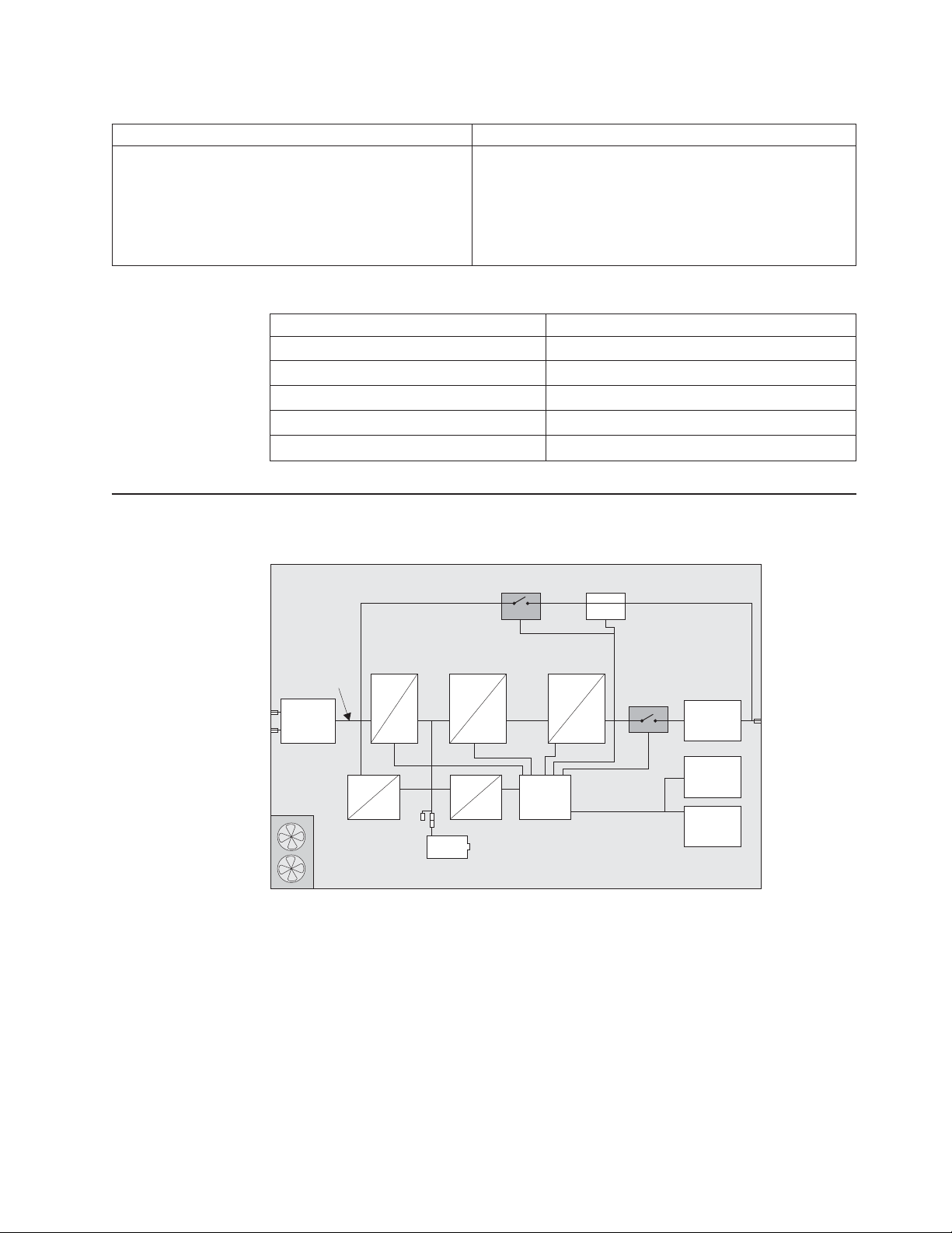
Table 1. 11000 VA LCD 5U rack UPS specifications (continued)
Specification 11000 VA LCD 5U rack UPS (200 V / 208 V / 230 V)
Efficiency (for fully charged battery) Normal mode:
≥92.5% (200 V)
≥93% (208 V / 220 V)
≥94% (230 V / 240 V)
Battery mode: ≥94%
High Efficiency mode: 96%
Table 2. 11000 VA UPS 3U extended battery module specifications
Specification 11000 VA UPS 3U extended battery module
Height 127 mm (5 in.)
Width 483 mm (19 in.)
Depth 740 mm (29.1 in.)
Weight 79 kg (174 lb)
Voltage 288V(24x12V,9Ah)
Internal circuit configuration
The following illustration shows the internal circuit configuration.
Chassis
I/P filter
Cooling
system
Mains1.
Rectifier
~
~
=
Flyback
charger
=
Converter
Internal
battery
=
=
Bypass SW
=
=
SPS
CNTL
BFP module
Inverter
=
~
~
INV SW
O/P filter
Comm
interface
LCD
display
Chapter 1. Introduction 5
Page 20

Notices and statements in this document
The caution and danger statements in this document are also in the multilingual
Systems Safety Notices document, which is on the IBM Documentation CD. Each
statement is numbered for reference to the corresponding statement in the Systems
Safety Notices document.
The following notices and statements are used in this document:
v Note: These notices provide important tips, guidance, or advice.
v Important: These notices provide information or advice that might help you avoid
inconvenient or problem situations.
v Attention: These notices indicate potential damage to programs, devices, or
data. An attention notice is placed just before the instruction or situation in which
damage could occur.
v Caution: These statements indicate situations that can be potentially hazardous
to you. A caution statement is placed just before the description of a potentially
hazardous procedure step or situation.
v Danger: These statements indicate situations that can be potentially lethal or
extremely hazardous to you. A danger statement is placed just before the
description of a potentially lethal or extremely hazardous procedure step or
situation.
6 11000 VA UPS and 11000 VA EBM: Installation and Maintenance Guide
Page 21

Chapter 2. Installing the uninterruptible power supply
This chapter shows the front and rear views of the uninterruptible power supply
(UPS) and extended battery module and includes information about the following
topics:
v Checking the package contents
v Connecting the extended battery module to the UPS
v Installing a remote emergency power-off connector
v Hard-wiring the UPS input (for licensed electrician only)
v UPS initial startup
You will need the following tools to install the UPS:
v One number 2 Phillips screwdriver (for use with the rack mount kit and terminal
block cover)
v One flat-blade screwdriver (for wiring the terminal block)
Inventory checklist
The UPS comes with the following items.
Note: Your UPS model might not come with all of the items in the following list.
v UPS
v Two bezels (upper and lower)
v Rack mount kit, including rails and mounting hardware
v Documentation package
v IBM UPS Manager CD (power-management software)
v Serial and USB communication cables
v Remote emergency power-off connector
v Shipping bracket (provides extra protection for the UPS when shipped in a rack
cabinet)
© Copyright IBM Corp. 2011 7
Page 22
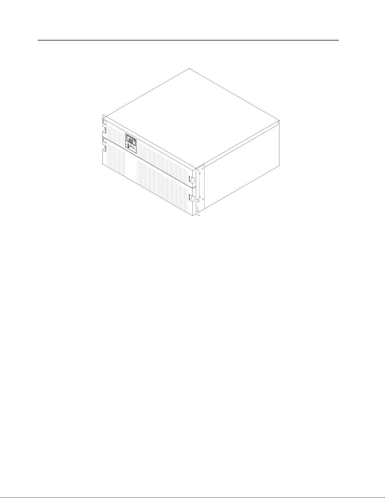
Front view of the UPS
The following illustration shows the front view of the UPS.
For more information about the control panel on the front of the UPS, see “Control
panel” on page 27.
208
UPS ON
100%
1
5
0
0
VA
V
6
/60hz
min
OK
8 11000 VA UPS and 11000 VA EBM: Installation and Maintenance Guide
Page 23
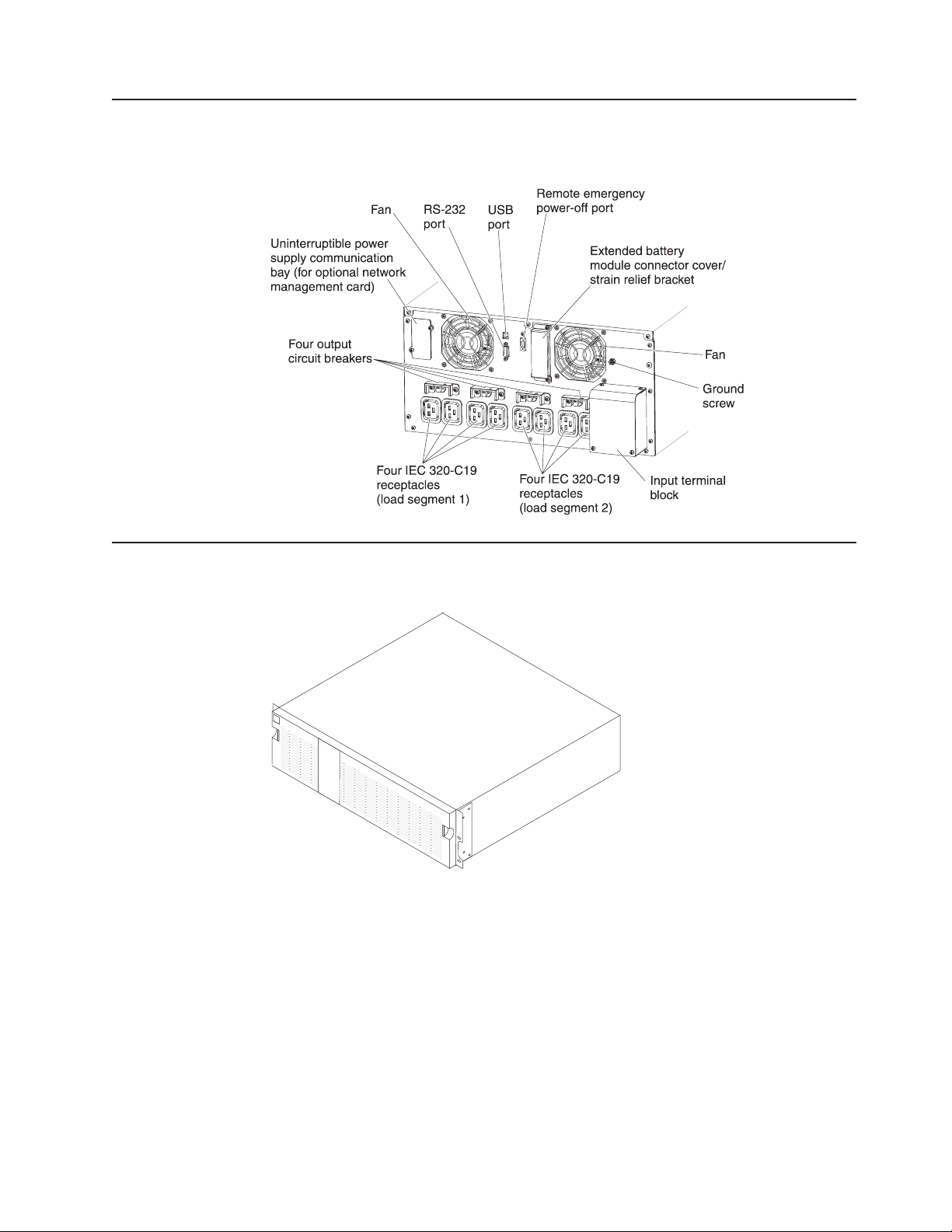
Rear view of the UPS
The following illustration shows the controls and connectors on the rear of the
11000 VA LCD 5U rack UPS (200 V / 208 V / 230 V).
Front view of the extended battery module
The following illustration shows the front view of the 3U extended battery module.
Chapter 2. Installing the uninterruptible power supply 9
Page 24
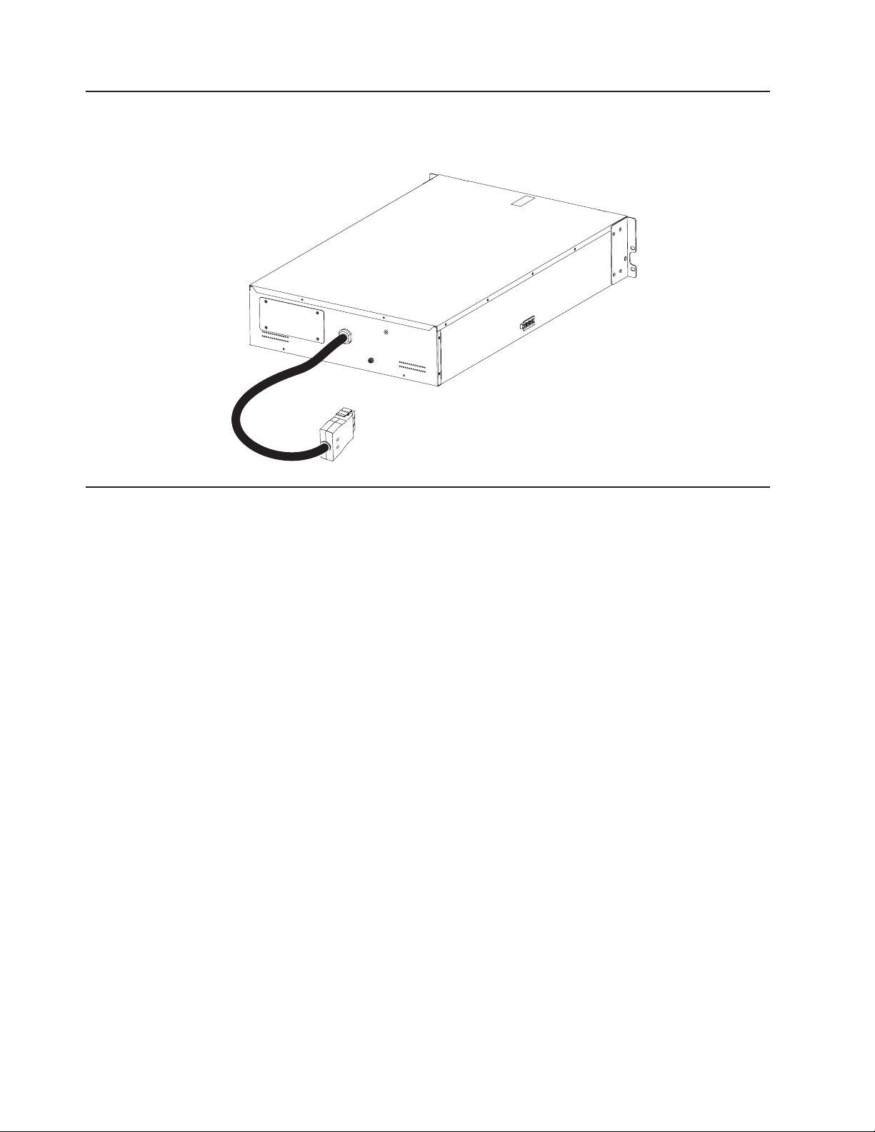
Rear view of the extended battery module
The following illustration shows the rear view of the 11000 VA 3U extended battery
module.
Rack installation
To install the UPS or extended battery module in a rack cabinet, see the IBM Rack
Installation Instructions document that comes with the rack mount kit.
10 11000 VA UPS and 11000 VA EBM: Installation and Maintenance Guide
Page 25
Connecting an extended battery module to the UPS
Important: A small amount of arcing might occur while you are connecting the
extended battery module to the UPS. This is normal and does not damage the unit
or cause any safety concern. Insert the extended battery module cable into the UPS
battery connector quickly and firmly.
Note: You can connect only one extended battery module to the UPS.
To connect an extended battery module to the UPS, complete the following steps:
1. Remove the two screws from the metal cover that protects the end of the
extended battery module power cord. Remove the metal cover. Save the cover
and screws for possible future use.
Metal cover
Chapter 2. Installing the uninterruptible power supply 11
Page 26
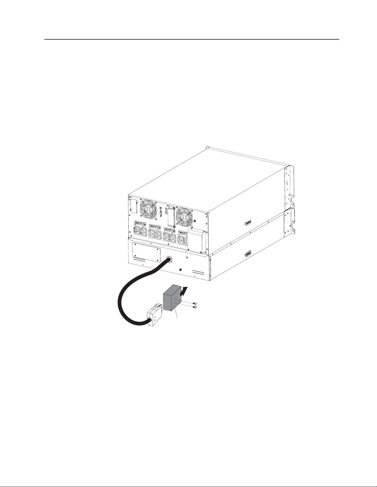
2. Remove the two screws and the battery connector cover from the rear panel of
the UPS as shown in the following illustration. Save the cover and screws for
possible future use.
Note: If the UPS is stored or used without an extended battery module, the
extended battery module connector cover must be installed as a safety
precaution.
Uninterruptible
power supply
Extended battery
module connector
cover
Extended battery
module
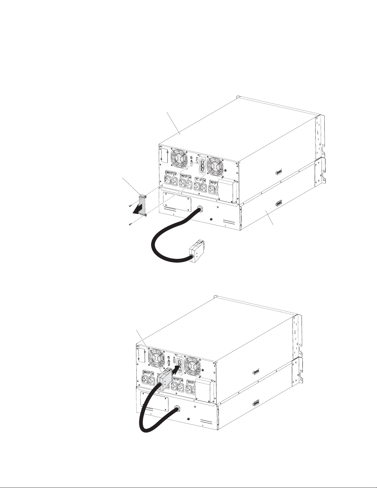
3. Align the extended battery module power cord with the extended battery module
connector on the UPS. Firmly press the power cord into the UPS until it snaps
into place.
Extended battery
module power cord
12 11000 VA UPS and 11000 VA EBM: Installation and Maintenance Guide
Page 27
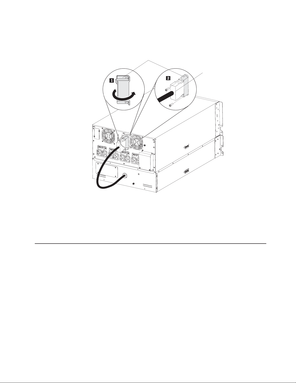
4. To provide strain relief and a secure connection for the extended battery module
power cord, rotate the extended battery module connector cover on its side and
position it under the extended battery module power cord 1.
Extended battery
module connector cover
Extended battery
module power cord
5. Secure the extended battery module connector cover to the UPS rear panel by
using the screws 2 that you removed in step 2 on page 12.
To remove the extended battery module power cord from the UPS, remove the two
screws that connect the extended battery module connector cover to the UPS.
Then, squeeze the two clamps on the sides of the plug and pull the plug out of the
extended battery module connector.
Completing the installation
To complete the installation of the UPS, complete the following steps:
1. If you are installing the IBM UPS Manager software, connect a computer to the
UPS by using one of the communication cables that come with the UPS. For
more information, see “Installing the UPS Manager software” on page 43.
2. If the rack cabinet has conductors for grounding or bonding of ungrounded
metal parts, connect the ground cable (purchased separately) to the ground
bonding screw. For the location of the ground bonding screw, see “Rear view of
the UPS” on page 9.
3. If an emergency power-off (disconnect) switch is required by local codes, see
“Installing the remote emergency power-off” on page 14 to install the remote
emergency power-off switch before you turn on the UPS.
4. Connect the devices that you want to protect to the applicable UPS output
receptacles. Do not turn on the devices. For information about load segments,
see “Configuring load segments” on page 38.
Chapter 2. Installing the uninterruptible power supply 13
Page 28

Notes:
1. Do not protect laser printers with the UPS because of the exceptionally high
power requirements of the heating elements.
2. Before you connect the UPS power cord to a power source, see “UPS initial
startup” on page 25.
Installing the remote emergency power-off
The UPS includes a remote emergency power-off connector that enables you to
turn off power at the UPS output receptacles from a customer-supplied switch in a
remote location. For example, you can use this feature to shut down the load and
the UPS by thermal relay, in the event of a room overtemperature condition. When
a remote emergency power-off is activated, the UPS shuts down the output and all
its power converters immediately. The UPS logic power remains on to issue an
alarm.
The remote emergency power-off feature shuts down the connected devices
immediately and does not follow the orderly shutdown procedure that is initiated by
any power-management software.
Any devices that are operating on battery power are also shut down immediately.
When the remote emergency power-off switch is reset, the connected devices do
not return to battery power until the UPS is restarted manually.
Notes:
1. The remote emergency power-off contacts are open by default. To change this
setting, see the REPO setting in Table 8 on page 32.
2. For Europe, the emergency switch requirements are detailed in Harmonized
document HD-384-48 S1, “Electrical Installation of the Buildings, Part 4:
Protection for Safety, Chapter 46: Isolation and Switching.”
Table 3. Remote emergency power-off connections
Wire function Terminal wire size rating Suggested wire size
2
Remote emergency power-off 4 - 0.32 mm
(12 - 22 AWG) 0.82 mm2(18 AWG)
3. The pins must be open to keep the UPS running. If the UPS shuts down
because the remote emergency power-off connector pins are shorted, restart
the UPS by reopening the remote emergency power-off connector pins and
turning on the UPS manually. Maximum resistance in the shorted loop is 10
ohm.
4. To avoid accidental load loss, always test the remote emergency power-off
function before you apply your critical load.
14 11000 VA UPS and 11000 VA EBM: Installation and Maintenance Guide
Page 29

To connect a remote emergency power-off switch, complete the following steps:
1. Turn off the UPS, disconnect all external cables, and make sure that the UPS is
disconnected from utility power.
2. Remove the remote emergency power-off connector from the accessory kit.
Note: Make sure that no jumper is installed in the remote emergency power-off
connector. If a jumper is installed, remove it before you connect to the remote
emergency power-off connector.
3. Install the remote emergency power-off connector in the remote emergency
power-off port on the rear of the UPS.
Note: The orientation of the remote emergency power-off port on your UPS
model might be different from what is shown in the following illustration. You
might have to rotate the remote emergency power-off connector to install it.
Remote emergency
power-off connector
Openings
4. Connect the switch or circuit to the remote emergency power-off connector on
the rear of the UPS, using insulated size 18 - 20 AWG (0.75 mm
2
- 0.5 mm2)
wire.
Note: A separate contact must simultaneously cause UPS input ac power to be
removed.
5. Make sure that the externally connected remote emergency power-off switch is
not activated. An activated remote emergency power-off switch disables power
to the UPS receptacles.
Chapter 2. Installing the uninterruptible power supply 15
Page 30

Hard-wiring the UPS input (for licensed electrician only)
CAUTION:
The product might be equipped with a hard-wired power cable. Ensure that a
licensed electrician performs the installation per the national electrical code.
(C022)
The 11000 VA UPS model requires a dedicated branch circuit that meets the
following requirements:
v A breaker that is wall-mounted and readily accessible to the operator:
A 63 A (for Europe) or 80 A (for North America) 2-pole circuit breaker to provide
short circuit and overcurrent protection.
(For Europe) The breaker meets the IEC/EN 60934 standard and has a contact
air gap of at least 3 mm.
v A two-pole disconnection device between the UPS output and the load (see the
circuit breaker diagram).
v 200 - 240 V ac, 50/60 Hz.
v Flexible metal conduit (for ease of service and maintenance).
The following illustration shows the circuit breaker diagram.
To hard-wire the UPS input, complete the following steps:
1. Turn off the utility power at the distribution point where you will connect the
UPS. Be absolutely sure that there is no power.
16 11000 VA UPS and 11000 VA EBM: Installation and Maintenance Guide
Page 31

2. Remove the four screws that secure the terminal block cover to the UPS. Save
the screws.
Input terminal
block cover
3. Punch a hole in the terminal block cover for the input conduit, using a round
knockout punch or similar device. The hole must accommodate a 19 - 25.4 mm
(0.75 - 1 in.) Intermediate Metal Conduit (IMC).
4. Pull the input wire through the conduit, leaving approximately 0.5 m (2 ft) of
exposed wire. Attach a flexible metal fitting to the end of the conduit.
5. Insert the conduit through the wiring access entry and attach the conduit fitting
to the panel. Strip 1.5 cm (0.5 in.) of insulation from the end of each incoming
wire.
6.
CAUTION: The UPS does not have an automatic protection device against
current backfeed. Install an external isolating device as shown in the following
illustration. Check for hazardous voltage between all terminals before operating
on this circuit.
External distribution panel
Q
L/L1
L/L1
N/L2
N/L2
T
B
Uninterruptible power supply
L/L1
N/L2
Coil remote switch
B
Magneto-thermal input main switch
Q
AC contactor rated 208 - 240 V, 68 A; 220 -
T
240 Vac, 68 A; or 220 - 240 Vac, 80 A
Neutral/L2
N/L2
L1 Line input
L/L1
Chapter 2. Installing the uninterruptible power supply 17
Page 32

7. Connect the input and ground wires to the terminal block according to the
following illustration and Table 4.
Terminal position
3
2
1
Table 4. UPS wiring specifications
2
Tightening
torque
1.69 Nm (15
inch-pounds)
Wire functions
Terminal
position
UPS wire
function
Terminal wire
size rating
Input 1 Input ground 16 - 35 mm
2 L2 / Neutral In
(8-2AWG)
3L1In
1
Use the following minimum wire size:
v 8 AWG for equipment grounding wire, 75°C copper wire minimum
v 4 AWG for input line and neutral wires, 75°C copper wire minimum
1
8. Replace the terminal block cover.
9. Continue to “UPS initial startup” on page 25.
18 11000 VA UPS and 11000 VA EBM: Installation and Maintenance Guide
Page 33

Connecting the UPS internal batteries
To connect the UPS internal batteries, complete the following steps:
1. Remove the UPS lower front bezel. Press the two side latches toward each
other to release the bezel, and pull the bezel away.
1
00
%
6
m
i
n
OKOK
2. Loosen the thumbscrew on the left battery retention bracket 1, slide the
bracket to the right 2, rotate the bracket out 3, and then remove it.
1
0
0
%
6
m
in
OKOK
L
Chapter 2. Installing the uninterruptible power supply 19
Page 34

3. Loosen the thumbscrew on the right battery retention bracket 1, slide the
bracket to the left 2, rotate the bracket out 3, and then remove it.
1
0
0
%
6
m
in
OKOK
R
4. Connect the three internal battery connectors.
1
0
0
%
6
m
in
OKOK
Note: A small amount of arcing might occur when you connect the batteries.
This is normal and does not damage the unit or present any safety concern.
20 11000 VA UPS and 11000 VA EBM: Installation and Maintenance Guide
Page 35

5. Reinstall the right battery retention bracket:
a. Slide the right battery retention bracket to the left and into the slot 1.
10
0
%
6
m
i
n
OKOK
R
b. Rotate the battery retention bracket toward the UPS 2. Make sure that the
internal battery connectors are out of the way.
c. Slide the battery retention bracket to the right 3 and tighten the
thumbscrew on the right battery retention bracket 4.
6. Reinstall the left battery retention bracket:
a. Slide the left battery retention bracket to the right and into the slot 1.
1
0
0
%
6
m
in
OKOK
L
b. Rotate the battery retention bracket toward the UPS 2. Make sure that the
internal battery connectors are out of the way.
c. Slide the battery retention bracket to the left 3 and tighten the thumbscrew
on the left battery retention bracket 4.
7. To attach the UPS lower front bezel, press the two side latches toward each
other, align the bezel underneath the upper bezel, and snap it into place.
1
0
0
%
6
m
in
OKOK
Chapter 2. Installing the uninterruptible power supply 21
Page 36

Disconnecting the UPS internal batteries
To disconnect the UPS internal batteries, complete the following steps:
1. Remove the UPS lower front bezel. Press the two side latches toward each
other to release the bezel, and pull the bezel away.
1
0
0
%
6
m
i
n
OKOK
2. Loosen the thumbscrew on the left battery retention bracket 1, slide the
bracket to the right 2, rotate the bracket out 3, and then remove it.
1
0
0
%
6
m
in
OKOK
L
22 11000 VA UPS and 11000 VA EBM: Installation and Maintenance Guide
Page 37

3. Loosen the thumbscrew on the right battery retention bracket 1, slide the
bracket to the left 2, rotate the bracket out 3, and then remove it.
1
0
0%
6
m
in
OKOK
R
4. Disconnect all three internal battery connectors.
1
0
0
%
6
m
in
OKOK
Chapter 2. Installing the uninterruptible power supply 23
Page 38

5. Reinstall the right battery retention bracket:
a. Slide the right battery retention bracket to the left and into the slot 1.
1
0
0
%
6
m
in
OKOK
R
b. Rotate the battery retention bracket toward the UPS 2. Make sure that the
internal battery connectors are out of the way.
c. Slide the battery retention bracket to the right 3 and tighten the
thumbscrew on the right battery retention bracket 4.
6. Reinstall the left battery retention bracket:
a. Slide the left battery retention bracket to the right and into the slot 1.
1
0
0
%
6
m
in
OKOK
L
b. Rotate the battery retention bracket toward the UPS 2. Make sure that the
internal battery connectors are out of the way.
c. Slide the battery retention bracket to the left 3 and tighten the thumbscrew
on the left battery retention bracket 4.
7. To attach the UPS lower front bezel, press the two side latches toward each
other, align the bezel underneath the upper bezel, and snap it into place.
1
0
0
%
6
m
in
OKOK
24 11000 VA UPS and 11000 VA EBM: Installation and Maintenance Guide
Page 39

UPS initial startup
To start the UPS for the first time, complete the following steps:
1. Make sure that the internal batteries are connected. For more information, see
2. If an optional extended battery module is installed, make sure that the
3. Make sure that all load segment circuit breakers are in the On position.
4. Turn on the main utility breaker. The UPS front panel display is illuminated.
5. Press the on/off button on the UPS front panel.
6. Press the down (
7. If an optional extended battery module is installed, see “Configuring the UPS
8. To set the date and time and to change other factory-set defaults, see
9. If you installed an optional remote emergency power-off switch, make sure that
10. Charge the batteries. With load, the internal batteries charge to 90% capacity
11. To prevent an UPS overload condition, connect one load at a time and make
“Connecting the UPS internal batteries” on page 19.
extended battery module is connected to the UPS. For more information, see
“Connecting an extended battery module to the UPS” on page 11.
The IBM startup screen changes to the UPS status summary screen. Standby
status is displayed on the front panel of the UPS.
After the startup is complete, the status changes according to the UPS
operating mode.
) button to check for active alarms or notices. Resolve any
active alarms before you continue. For more information, see Chapter 6,
“Troubleshooting,” on page 55.
If there are no active alarms, the message No Active Alarms is displayed.
for an extended battery module” on page 40.
Chapter 3, “Operating the uninterruptible power supply,” on page 27.
the function is working correctly by performing the following tests:
v Activate the external remote emergency power-off switch. Make sure that
the status changes on the UPS are displayed.
v Deactivate the external remote emergency power-off switch and restart the
UPS.
in less than 3 hours. However, you must charge the batteries for 48 hours after
installation or long-term storage.
sure that each protected device starts up completely before you connect the
next load.
Notes:
1. At initial startup, the UPS sets system frequency according to input line
frequency (input frequency auto sensing is enabled by default). After initial
startup, auto sensing is disabled until you manually enable it by using the output
frequency setting.
2. At initial startup, input voltage auto sensing is enabled by default. After the
subsequent startup, auto sensing is disabled until you manually enable it by
using the output voltage setting.
3. Battery start is automatically enabled after one power cycle.
4. The Site Wiring Fault is disabled by default.
Chapter 2. Installing the uninterruptible power supply 25
Page 40

26 11000 VA UPS and 11000 VA EBM: Installation and Maintenance Guide
Page 41

Chapter 3. Operating the uninterruptible power supply
This chapter describes how to use the uninterruptible power supply (UPS) and
includes information about the following topics:
v Control panel
v Operating modes
v Turning on and turning off the UPS
v Display functions
v Transferring the UPS between modes
v Setting power strategy
v Retrieving the alarm history
v Behavior on overload
v Configuring load segments, battery settings, and automatic restart
Control panel
The following illustration shows the display and controls on the front of the UPS.
LCD control panel
100%
11000
VA
6
min
230V/60HZ
UPS ON
Escape
button
On/Off
button
The UPS has a graphical liquid crystal display (LCD) with dual color backlight.
Standard backlight is used to light the display with white text and a blue
background. The display flashes if any alarms are active.
There are three control buttons and one on/off button on the front panel:
Escape (X): Press this button to return to the previous menu without running a
command or saving any changes.
Down (
this button provides faster scrolling on some menus.
): Press this button to scroll down to the next menu option. Holding down
Down
button
OK
OK
button
OK: Press this button to select the current menu or option. On the following
screens, press and hold this button longer than 1 second:
v On the User Setting screens, to save the displayed setting.
© Copyright IBM Corp. 2011 27
Page 42

v On the Meter and Notice/Alarm screens, to lock the screen (prevent the screen
On/off: Press this button to turn on the UPS. Press and hold this button for 3
seconds to turn off the UPS.
The following display button shortcuts are available.
Table 5. Display button shortcuts
Shortcut Buttons
Disable the battery start
feature
Set the display to English Press and hold the escape (X), down (
Operating modes
The UPS has the following operating modes:
v Normal
v High Efficiency
v Converter
v Battery
v Bypass
v Standby
from returning to its default after timeout). A locked screen displays a small key
image near the status icon. To unlock the screen, press any button to perform its
usual function.
Press and hold the escape (X) and down (
seconds. The UPS beeps once to indicate that Battery Start is
disabled for the next ac power cycle.
5 seconds.
) buttons for 3
), and OK buttons for
Note: If the UPS is unable to continue operating normally, it might attempt to save
data and follow an orderly shutdown sequence. However, some unrecoverable
failures and overload conditions cause the UPS to transfer to Fault mode without
saving data, and turn off immediately to protect the UPS and the load from damage.
Normal mode
The UPS supplies the load power from utility power. The UPS monitors and
charges the batteries as needed and provides filtered power protection to your
equipment.
High Efficiency mode
The UPS supplies the load power from the bypass source and stands ready to
automatically transfer to standard double-conversion (Normal) operation as needed.
The battery recharges when necessary. The High Efficiency setting minimizes heat
contribution to the rack environment.
28 11000 VA UPS and 11000 VA EBM: Installation and Maintenance Guide
Page 43

Converter mode
Battery mode
Bypass mode
Standby mode
The UPS supplies the load from utility power while acting as a frequency converter,
locking the UPS into a stable output frequency and transferring to Battery mode as
necessary. Bypass mode is not available. Use Converter mode to lock the UPS
output frequency at 50 Hz or 60 Hz to suit power-sensitive equipment, or to provide
50 Hz output when the available standard utility input is 60 Hz (or the reverse).
The UPS supplies the load power from battery. The status text flashes, and the
UPS beeps every 5 seconds. When the utility power returns, the UPS transfers to
Normal mode operation while the battery recharges.
The UPS supplies the load power through an automatic internal bypass. Battery
mode is not available. The UPS transfers to Bypass mode when you activate
Bypass mode through the front panel (manual bypass) or when the UPS detects a
condition that requires bypass (automatic bypass).
When the UPS is turned off and remains connected to the power source, the UPS
is in Standby mode. The UPS is not supporting the load but is ready to assume the
load on command.
Turning on the UPS
After the UPS is connected to the power source, it enters Standby mode.
To turn on the UPS, press the on/off button for approximately 1 second. The display
changes from the start screen to the UPS Status Summary screen and shows the
Standby icon flashing while the UPS starts.
Starting the UPS on battery
Note: Before you use this feature, the UPS must have been powered by utility
power at least one time.
To turn on the UPS without using utility power, press and hold the on/off button for
3 seconds. The UPS supplies power to the connected devices, and it switches into
Battery mode.
Turning off the UPS
To turn off the UPS, complete the following steps:
1. Prepare the connected devices for shutdown.
2. Press and hold the on/off button until the long beep ceases (approximately 3
seconds). The UPS switches to Standby mode (if utility power is available) and
removes power from the connected devices.
Note: You must turn off the UPS at the power source; otherwise, it remains in
Standby mode. After the power source is removed, the UPS fully shuts down in
10 seconds.
Chapter 3. Operating the uninterruptible power supply 29
Page 44

Display functions
The UPS provides information about the load status, events, measurements,
identification, and settings through the front panel display.
While any screen is displayed, press the escape (X) button until the main menu is
displayed, and then press the down (
menu choices:
v System Status
v Alarm History
v Meters
v Control Screens
v Model Information
v Configuration
Press the OK button to select a menu item.
System status
The System Status provides the following information:
v Battery status, including state and change level
v Status summary (load percentage, output power, output voltage and frequency,
v Notice or alarm status, if any are present
) button to scroll through the following main
and mode)
Alarm history
If the message ALARM is displayed, press the down () button to display the active
notices, alarms, and battery status messages. For more information, see Table 6
and Chapter 6, “Troubleshooting,” on page 55.
The following table describes the available battery status messages. Only one
battery status is available at a time.
Table 6. Battery status messages
Battery status Description
Battery charging Batteries are charged in constant current mode.
Battery floating Batteries are charged in constant voltage mode.
Battery resting Batteries are connected but are not being charged or discharged.
(This is part of the normal charging cycle.)
Battery discharging Batteries are discharging.
Battery disconnected Batteries are unavailable because they are disconnected.
The alarm history holds up to 50 events. You can scroll through the event screens,
beginning with the most recent event.
Note: The date format is dependent on the language selection.
The first row of each alarm history screen contains the date (MM/DD/YYYY) and
time (hh:mm:ss) at which the event occurred. The second row contains the type of
event and code. The event description begins on the third row and might continue
30 11000 VA UPS and 11000 VA EBM: Installation and Maintenance Guide
Page 45

to the fourth row. The bottom-right corner of the alarm history screen displays two
numbers: an ordering number of the event in the log, followed by the total number
of events in the log.
If there are no events in the log, the message No events in log is displayed on the
alarm history screen.
For more information, see “Retrieving the alarm history” on page 37.
Meters
The meters screens provide the following meters information:
v Output watts, VA, current, power factor, voltage, and frequency
v Input voltage and frequency
v Battery voltage and percentage charged
v DC bus voltages
Control screens
The following table describes the available control screens.
Table 7. Control screens
Control screen Description
Go to Bypass Transfers the UPS system to internal Bypass mode.
When the Go to Bypass command is issued, the screen displays the Manual
Bypass Comment Sent message for 5 seconds. The option then changes to Go to
Normal.
When the Go to Normal command is issued, the screen displays the Normal Mode
Command Sent message for 5 seconds. The option then changes to Go to Bypass.
Battery test Schedule Battery Test: yes | Cancel Battery test: no
Starts a manual battery test.
See “Testing a battery” on page 54.
Reset error state Reset Alarms: yes | no
Manually clears any latched alarms, such as bad battery detected or DC Bus
OV/UV, and then performs a self-diagnostics test of the LCD, alarm sounds, and
fans.
If a bad battery alarm was also active, resets the battery test status to Not
Tested.
Load segments Load segment 1: on | off
Load segment 2: on | off
These on/off commands override automatic load segment on/off controls that are
made by the Automatic Start Delay and Automatic On Battery Shutdown settings.
See “Configuring load segments” on page 38.
Restore factory settings Restore Factory Settings: yes | no
Available only in Standby mode.
Restoring the factory settings:
v Returns all user-configurable EEPROM settings to default factory settings
v Resets all pending on/off commands
v Clears the alarm history and resets all statistic values and time stamps
v Resets the battery test status
v Initiates the Self Diagnostics test
Chapter 3. Operating the uninterruptible power supply 31
Page 46

Model information
The model information screens display the following information about the UPS:
v Model/Type: Chassis style and supply power rating
v MT, Product ID, SN: Machine type, product identification (model number), serial
number
v NMC firmware: Firmware version for the network management card
v NMC IP address: IP address for the network management card
v UPS firmware: Firmware version for the UPS
Note: The network management card firmware screens are displayed only if an
IBM Network Management Card is installed. See “IBM Network Management Card”
on page 45.
Configuration
Only the available options are displayed.
User settings are not protected by default. You can enable the password through
the User Password setting.
The following table describes the options that you can change.
Table 8. Configuration settings
Description Available settings Default setting
Change language [English] [French] [German] [Spanish] [Japanese] [Simplified
Chinese] [Russian] [Korean] [Traditional Chinese]
User password [Enabled] [Disabled]
English
Disabled
If the user password is enabled, the default password is USER.
Note: If you enter an incorrect password, the message Wrong
Password is displayed. Press any button to return to the password
screen and retry the password.
Audible alarms [Enabled] [Disabled]
Note: If you disable audible alarms, it takes effect instantly and
remains disabled, even after a power cycle. This differs from the
mute feature, by which the horn is temporarily silenced when any
button is pressed but turns on again if a new alarm is triggered.
Set date and time Set the month, day, year, hours, minutes, and seconds
Date: mm/dd/yyyy 01/01/2010
Time: hh:mm:ss 12:00:00
Notes:
1. The date format is dependent on the language selection.
2. Time is a 24-hour clock.
Control commands
from serial port
[Enabled] [Disabled]
If enabled, control commands are accepted through the serial
port, USB ports, or option card.
If control commands are disabled, configuration and load control
commands are restricted to LCD only.
Enabled
Enabled
32 11000 VA UPS and 11000 VA EBM: Installation and Maintenance Guide
Page 47

Table 8. Configuration settings (continued)
Description Available settings Default setting
Output voltage [200V] [208V] [220V] [230V] [240V] [Auto sensing]
Note: Numerical output voltage settings that are configured in
Standby mode take effect immediately. Auto sensing and any
settings that are configured outside of Standby mode take effect
after the next power off and restart. Selecting auto sensing
Auto sensing
Note: The default auto
sensing runs once to set
the output voltage and
then is disabled.
disables the battery start feature until after the next successful
startup on utility power.
Output frequency [50Hz] [60Hz] [Auto sensing]
Note: Numerical output frequency settings that are configured in
Standby mode take effect immediately. Auto sensing and any
settings that are configured outside of Standby mode take effect
after the next power off and restart. Selecting auto sensing
Auto sensing
Note: The default auto
sensing runs once to set
the output frequency and
then is disabled.
disables the battery start feature until after the next successful
startup on utility power.
Overload alarm level [10%] [20%] [30%]...[100%]
100%
If 100%, the UPS issues an Output Overload alarm at load >
100%.
Note: Output Overload Level 1 by default is set to 100% and is
configurable from 10% to 100% in 10% increments through the
LCD setting menu. This enables you to be alerted before the
UPS has reached its rated capacity limits.
Power strategy [Normal] [High Efficiency] [Converter]
Normal
See “Setting the power strategy” on page 36.
Automatic start delay [Off] [0s] [1s] [2s]...[32767s]
0s for Load Segment 1
1s for Load Segment 2
See “Configuring load segments” on page 38.
Automatic on battery
[Off] [0s] [1s] [2s]...[32767s]
Off
shutdown
See “Configuring load segments” on page 38.
Site wiring fault alarm [Enabled] [Disabled] Disabled
Bypass voltage low
limit
[-6%] [-7%]...[-20%] of nominal
The Bypass operation is disabled if the measured bypass voltage
-15% of nominal
level is below the nominal output voltage (-15%).
Note: The Qualify Bypass setting might overrule the Bypass
Voltage Low Limit setting.
Bypass voltage high
limit
[+6%] [+7%]...[+20%] of nominal
The Bypass operation is disabled if the measured bypass voltage
+10% of nominal
level is above the nominal output voltage (+10%).
Note: The Qualify Bypass setting might overrule the Bypass
Voltage High Limit setting.
Chapter 3. Operating the uninterruptible power supply 33
Page 48

Table 8. Configuration settings (continued)
Description Available settings Default setting
Qualify bypass [Always] [Never] [Bypass Disabled]
If Always is selected, the Bypass operation is allowed when:
v Bypass voltages > the value set for Bypass Voltage Low Limit
v Bypass voltages < the value set for Bypass Voltage High Limit
v Bypass frequency > (nominal frequency -3 Hz)
v Bypass frequency < (nominal frequency +3 Hz)
v Inverter is synchronized with Bypass when unsynchronized
transfers are disabled by the value set for Unsynchronized
Transfers
If Never is selected, the Bypass operation is always allowed, if
the utility is within the UPS operating limits; voltage and
frequency limits are not in use. If Bypass Disabled is selected,
the Bypass operation is prohibited.
Extended battery
modules (EBMs)
Battery low alarm [Immediate] [2 min] [3 min] [5 min]
Automatic battery tests [Enabled] [Disabled]
[0] [1]
See “Configuring the UPS for an extended battery module” on
page 40.
If you select a value, the battery low alarm is triggered when the
set amount of backup time (approximately) remains in the
batteries.
Always
0
3 minutes
Enabled
See “Running automatic battery tests” on page 41.
Clear alarm history The number after “Total events” shows how many events are
currently stored in the log. Press the OK button for 1 second to
reset the event count to zero and clear the log.
LCD contrast [-5], [-4], [-3], [-2], [-1], [+0], [+1], [+2], [+3], [+4], [+5]
The display contrast is adjustable from -5 to +5. This range
covers the maximum adjustment for contrasting the background
with the text in the visual display of the control panel.
REPO input polarity [Open] [Closed]
If Open is selected, the normally open contacts activate the
alarm when the contacts close. If Closed is selected, the
normally closed contacts activate the alarm when the contacts
open.
Not applicable
[+0]
Open
34 11000 VA UPS and 11000 VA EBM: Installation and Maintenance Guide
Page 49

Transferring the UPS between modes
Transferring between modes includes:
v Transferring from Normal to Bypass mode
v Transferring from Bypass to Normal mode
Transferring from Normal to Bypass Mode
To transfer from Normal to Bypass mode, complete the following steps:
1. From the main menu, press the down ( ) button to scroll to the Control menu,
and press the OK button.
2. Press the down (
The text on the screen changes to Manual Bypass Command Sent.
) button to scroll to Go to Bypass, and press the OK button.
Transferring from Bypass to Normal Mode
To transfer from Bypass to Normal mode, complete the following steps:
1. From the main menu, press the down ( ) button to scroll to the Control menu,
and press the OK button.
2. Press the down (
The text on the screen changes to Normal Mode Command Sent.
) button to scroll to Go to Normal, and press the OK button.
Chapter 3. Operating the uninterruptible power supply 35
Page 50

Setting the power strategy
The UPS has the following three settings for power strategy:
v Normal. The UPS operates in Normal mode (powering the load from utility
power).
v High Efficiency. The UPS operates in High Efficiency mode (powering the load
from the bypass source but ready to transfer to Normal mode as needed). The
UPS is highly sensitive to line fluctuations and transfers out of High Efficiency
mode at ±5% of nominal voltage or ±1% of nominal frequency. If the UPS
transfers to Normal mode, the UPS automatically transfers back to High
Efficiency mode after 5 minutes of stable power. Transfers to High Efficiency
mode are limited to three times in 1 hour.
v Converter. The UPS operates as a frequency converter, powering the load from
acceptable utility power while providing a stable output frequency. Bypass
operation and bypass-related alarms are disabled.
The following table describes the UPS behavior in Converter mode in detail. To set
the output frequency, see “Configuration” on page 32.
Table 9. UPS behavior in Converter mode
Output
frequency
Load
≤50% 50 Hz 47 - 53 47 - 53 UPS in Converter mode synchronizes the
>50% 50 Hz 47 - 53 47 - 53 UPS in Converter mode synchronizes the
setting
60 Hz 57 - 63 57-63 UPS in Converter mode synchronizes the
60 Hz 57 - 63 57 - 63 UPS in Converter mode synchronizes the
Input frequency
(Hz)
45 - 46 or 54 - 65 50 UPS in Converter mode converts the input
<45 or >65 50 UPS transfers to Battery mode to provide
45 - 56 or 64 - 65 60 UPS in Converter mode converts the input
<45 or >65 60 UPS transfers to Battery mode to provide
45 - 46 or 54 - 55 50 UPS in Converter mode converts the input
<45 or >55 50 UPS transfers to Battery mode to provide
55 - 56 or 64 - 65 60 UPS in Converter mode converts the input
<55 or >65 60 UPS transfers to Battery mode to provide
Output frequency
(Hz) UPS behavior
output frequency with the input frequency.
frequency to 50 Hz output frequency.
50 Hz output frequency.
output frequency with the input frequency.
frequency to 60 Hz output frequency.
60 Hz output frequency.
output frequency with the input frequency.
frequency to 50 Hz output frequency.
50 Hz output frequency.
output frequency with the input frequency.
frequency to 60 Hz output frequency.
60 Hz output frequency.
36 11000 VA UPS and 11000 VA EBM: Installation and Maintenance Guide
Page 51

To set the power strategy, complete the following steps:
1. Make sure that the UPS is in Standby mode.
2. From the main menu, press the down (
menu, and press the OK button.
3. Press the down (
button.
4. Press the down (
and press the OK button.
5. Press the OK button for 1 second to confirm.
Note: The UPS tests the bypass source for 5 consecutive minutes of stable power
before it transfers to High Efficiency mode.
Retrieving the alarm history
To retrieve the alarm history through the display, complete the following steps:
1. From the main menu, press the down (
menu, and press the OK button.
2. Press the down (
alarms.
3. Press the escape (X) button to return to the previous menu.
) button to scroll to the Configuration
) button to scroll to Power Strategy, and press the OK
) button to select the power strategy that you want to set
) button to scroll to the Alarm history
) button to scroll through the listed events, notices, and
Behavior on overload
The following table explains how the UPS responds to an overload condition.
Table 10. Behavior on overload
Overload
severity Load level On utility power
Level 1 100% to
101%
Level 2 102% to
110%
Level 3 > 110% Transfer to Bypass
Overload alarm only and
support load indefinitely
Transfer to Bypass after 12
seconds (±1 sec)
If Bypass is not available,
transfer to Fault mode
after 12 seconds (±1 sec)
immediately
If Bypass is not available,
transfer to Fault mode in
300 ms to 1 sec
On Bypass / High
Efficiency On Battery / Converter
Overload alarm only and
support load indefinitely
Transfer to Fault mode in
2 minutes (± 1 sec)
Transfer to Fault mode in
300 ms to 1 sec
Overload alarm only,
support load until low
battery shutdown level is
reached
Transfer to Fault mode
after 12 seconds (±1 sec)
or until low battery
shutdown level is reached
Transfer to Fault mode in
300 ms to 1 sec
Chapter 3. Operating the uninterruptible power supply 37
Page 52

Configuring load segments
Load segments are sets of receptacles that can be controlled through the LCD, by
the network management card, or by power-management software, providing an
orderly shutdown and startup of the connected devices. For example, during a
power outage, you can keep key devices running while you turn off other devices.
This feature enables you to save battery power. For more information, see your
power-management software documentation.
The UPS has two load segments that are shown as shaded areas in the following
illustration. The shading does not appear on the chassis.
Controlling load segments through the display
To control the load segments through the display, complete the following steps:
1. From the main menu, press the down ( ) button to scroll to the Control menu,
and press the OK button.
2. Press the down (
button.
3. Press the down (
press the OK button.
4. Press the down (
5. Press the OK button for 1 second to confirm.
6. Repeat step 3 to step 5 to set the other load segment, if applicable.
) button to scroll to Load Segments, and press the OK
) button to scroll to the load segment that you want and
) button to set the selected load segment to On or Off.
38 11000 VA UPS and 11000 VA EBM: Installation and Maintenance Guide
Page 53

Configuring automatic start delay
The load segments turn on automatically after the utility power returns, if they were
shut down by any of the following means:
v The on/off button
v An external command with the auto-restart option
v Battery under voltage state
v Automatic on battery shutdown command
You can change the length of the restart delay time or disable automatic restart. To
set the restart delay times for each load segment, complete the following steps:
1. From the main menu, press the down (
menu, and press the OK button.
2. Press the down (
OK button.
3. Press the down (
press the OK button.
4. Press the down (
You can specify one of the following options for the restart delay time for each
load segment:
v Select zero seconds to restart immediately.
v Select 1 - 32767 seconds to delay for the specified time.
v Select Off.
5. Press the OK button for 1 second to confirm.
6. Repeat step 3 to step 5 to set the other load segment, if applicable.
) button to scroll to Automatic Start Delay, and press the
) button to select the load segment that you want to set and
) button to select the restart delay for the load segment.
) button to scroll to the Configuration
Notes:
1. Load segment on/off commands that are issued through the Control menu
override the user settings for load segments.
2. A single load segment delay applies to both receptacles. However, there is an
additional automatic 1-second delay between closing segments 1 and 2. The
delay is always present when an On command is issued for both segments at
the same time.
Configuring automatic on battery shutdown
You can use the Automatic on Battery Shutdown setting to configure how soon
the load segment shuts down when the UPS transfers to Battery mode:
v If the Automatic on Battery Shutdown setting is set to Off (default), the load
segment turns off only when you manually press the button, issue an external
command, or turn it off through the display (Control > Load Segments).
v If the Automatic on Battery Shutdown setting is set to zero seconds (0s), the
load segment turns off automatically when the UPS on Battery state is activated.
v If you select a value, the load segment turns off automatically after the selected
delay while the UPS operates on battery, but the shutdown is canceled if the
utility power returns before the delay has expired.
Chapter 3. Operating the uninterruptible power supply 39
Page 54

To set the shutdown times for each load segment, complete the following steps:
1. From the main menu, press the down (
menu, and press the OK button.
2. Press the down (
press the OK button.
3. Press the down (
press the OK button.
4. Press the down (
5. Press the OK button for 1 second to confirm.
6. Repeat step 3 to step 5 to set the other load segment, if applicable.
) button to scroll to Automatic on Battery Shutdown, and
) button to select the load segment that you want to set and
) button to select the shutdown delay for the load segment.
) button to scroll to the Configuration
Configuring battery settings
Configure the UPS settings for an installed extended battery module, including
whether to run automatic battery tests.
Configuring the UPS for an extended battery module
If the UPS is not configured for the extended battery module, the UPS reports less
battery time remaining on the UPS front panel and to any remote software. You
might receive a shutdown warning prematurely.
Conversely, if the UPS is configured for the extended battery module but the
extended battery module is not connected to the UPS, the UPS reports more
battery time remaining, and it might shut down before it issues a warning.
Note: The default configuration is to issue an alarm when the batteries reach their
lowest limit, which enables an orderly shutdown.
For the maximum battery runtime when you are using power management software,
complete the following steps to configure the UPS for the extended battery module:
1. From the main menu, press the down (
menu, and press the OK button.
2. Press the down (
the OK button.
3. Press the down (
Configuration Setting
UPS only (internal batteries) 0 (default)
UPS and one extended battery module 1
Note: Runtime is automatically adjusted according to present load levels and
whether an extended battery module is configured.
4. Press the OK button for 1 second to confirm.
) button to scroll to External Battery Modules, and press
) button to select the battery number value that you want.
) button to scroll to the Configuration
40 11000 VA UPS and 11000 VA EBM: Installation and Maintenance Guide
Page 55

Running automatic battery tests
The automatic discharge test is enabled by default and runs during the transition
from Float to Rest mode. After the test is complete, the charge cycle restarts to
completely charge the batteries and then continues to Rest mode. The automatic
test runs approximately once every three months and does not run again until after
three more Float to Rest mode transitions. If a manual battery test is requested, the
automatic battery test timer is reset so that it does not run for the next three
months.
For an automatic battery test to run, make sure that the following requirements are
met:
v The Automatic Battery Tests setting is enabled. (See “Configuring automatic
battery tests.”)
v The batteries are fully charged.
v The UPS is in Normal mode or High Efficiency mode with no active alarms.
v The load is greater than 10%.
v The bypass voltage is usable.
Configuring automatic battery tests
To configure the automatic battery tests, complete the following steps:
1. From the main menu, press the down (
menu, and press the OK button.
2. Press the down (
OK button.
3. Press the down (
battery test.
4. Press the OK button for 1 second to confirm.
) button to scroll to Automatic Battery Tests, and press the
) button to select whether to enable or disable the automatic
) button to scroll to the Configuration
Configuring automatic restart
The UPS automatically restarts if the utility power returns after the output was shut
off because of depleted batteries, a shutdown input signal, or an automatic
shutdown command.
You can set the load segment for the amount of time to delay the restart when utility
power returns by using the Automatic Start Delay setting (see Table 8 on page 32).
Chapter 3. Operating the uninterruptible power supply 41
Page 56

42 11000 VA UPS and 11000 VA EBM: Installation and Maintenance Guide
Page 57

Chapter 4. Additional uninterruptible power supply features
This chapter describes the following uninterruptible power supply (UPS) features:
v IBM UPS Manager software
v Communication ports (RS-232 and USB)
v Network management card
v Environmental monitoring probe
Installing the UPS Manager software
The UPS comes with the IBM UPS Manager software. The management software
provides up-to-date graphics of UPS power and system data and power flow. It also
gives you a complete record of critical power events, and it notifies you of important
UPS or power information. If there is a power outage and the UPS battery power
becomes low, the software can automatically shut down the system to protect the
data before the UPS shutdown occurs.
You can install the IBM UPS Manager software on a computer running a Microsoft
Windows or Linux operating system, as either a stand-alone application or part of a
network. To install the software, complete the following steps:
1. Connect a computer to either the RS-232 port or USB port on the UPS. See
“RS-232 and USB communication ports.”
2. Insert the IBM UPS Manager CD that comes with the UPS into the CD or DVD
drive. If the Software Wizard install menu does not automatically open, see the
CD_ReadMe.txt file and follow the steps to manually open the wizard.
3. Run the Software Wizard, which guides you through the installation process.
For more information about configuring and operating the software, see the online
help.
For more information about disabling control commands from the software, see the
Control commands from serial port setting in Table 8 on page 32.
RS-232 and USB communication ports
The UPS has an RS-232 port and a USB port that you can use for UPS monitoring,
control, and firmware updates. After communication is established between the UPS
and a computer, you can use the IBM UPS Manager software to exchange data
between the UPS and the computer. The software polls the UPS for detailed
information about the status of the power environment. If a power emergency
occurs, the software initiates the saving of all data and an orderly shutdown of the
devices that are connected to the UPS.
For the communication port locations, see “Rear view of the UPS” on page 9.
Note: Only one of the communication ports can be active at one time. The USB
port has priority over the RS-232 port.
© Copyright IBM Corp. 2011 43
Page 58

RS-232 port
To establish communication between the UPS and a computer, connect one end of
the serial communication cable that comes with the UPS to the RS-232 port on the
UPS. Connect the other end of the serial cable to the RS-232 port on a computer.
The cable pins for the RS-232 connector are identified in the following illustration.
The pin functions are described in Table 11.
RS-232
connector
9
8
7
6
5
4
3
2
1
Table 11. RS-232 connector pin assignments
Pin Signal name Function Direction from the UPS
1 Unused Not applicable
2 Tx Transmit to external device Out
3 Rx Receive from external device In
4 Unused Not applicable
5 GND Signal common (tied to
Not applicable
chassis)
6 Unused Not applicable
7 Unused Not applicable
8 Unused Not applicable
9 Unused Not applicable
Note: Unused pins must remain free on all models.
44 11000 VA UPS and 11000 VA EBM: Installation and Maintenance Guide
Page 59

USB port
The UPS can communicate with a USB-compliant computer by using the IBM UPS
Manager software, which is compatible with a human interface device (HID). To
establish communication between the UPS and a computer, connect the USB cable
that comes with the UPS to the USB port on the UPS. Connect the other end of the
USB cable to a USB port on a computer.
IBM Network Management Card
Each UPS has one available communication bay, which supports an IBM Network
Management Card. The network management card must be purchased separately.
After you install a network management card, you can perform the following tasks:
v Connect an IBM Environmental Monitoring Probe (purchased separately) to the
UPS
v Use power management software to control load segments, set the time and
date, and configure other settings
v Update the UPS firmware
Note: You do not have to shut down the UPS before you install a network
management card.
For information about installing, configuring, and using the network management
card, see the IBM Network Management Card User's Guide on the IBM
Documentation CD that comes with the UPS.
For details about disabling control commands from the network management card,
see the Control commands from serial port setting in Table 8 on page 32.
IBM Environmental Monitoring Probe
The IBM Environmental Monitoring Probe (purchased separately) is a connectivity
device that enables you to remotely monitor the temperature, humidity, and status
of two contact devices through a standard web browser, providing greater
power-management control and flexible monitoring.
When the environmental monitoring probe is connected to the network management
card, temperature and humidity readings are automatically displayed in the web
interface. To access the readings, you must run a web browser and connect to the
network management card IP address.
For more information about connecting and configuring the environmental
monitoring probe, see the IBM Network Management Card User's Guide on the IBM
Documentation CD that comes with the UPS.
Chapter 4. Additional uninterruptible power supply features 45
Page 60

46 11000 VA UPS and 11000 VA EBM: Installation and Maintenance Guide
Page 61

Chapter 5. Hardware maintenance information
This chapter contains information about IBM customer replaceable units (CRUs)
and field replaceable units (FRUs) for the uninterruptible power supply (UPS) and
instructions for replacement parts that are not installed during a typical installation.
Replaceable UPS components
The replaceable components in the UPS are Tier 1 customer replaceable units
(CRUs). Replacement of Tier 1 CRUs is your responsibility. If IBM installs a Tier 1
CRU at your request, you will be charged for the installation.
For information about the terms of the warranty and getting service and assistance,
see Appendix A, “Getting help and technical assistance,” on page 63 and the
Warranty Information document that comes with the product.
Important: Next-day delivery of the batteries might not be possible in all locations
because of transportation and logistics.
Table 12. 11000 VA UPS CRU listing
Description MTM or part number CRU part number (Tier 1)
UPS chassis
11000 VA (208 V / 230 V)
Battery module (This CRU part contains the two
battery modules that are required for the UPS.)
Bezel, upper (11000 VA UPS) 5395-9KX 69Y6095
Bezel, lower (11000 VA UPS) 5395-9KX 81Y2325
USB cable 69Y6073
RS-232 cable 69Y6074
Rack mount kit 69Y6094
Remote emergency power-on (REPO) switch 69Y6075
Environmental monitoring probe kit 41Y9210
Network management card 46M4112
Network management card setup cable (serial
communication cable)
5395-9KX 81Y2321
5395-9KX 81Y2323
81Y2372
Table 13. 11000 VA extended battery module CRU listing
Description MTM or part number CRU part number (Tier 1)
Extended battery module (11000 VA) 69Y1986 81Y2330
Bezel, 3U extended battery module 81Y2325
UPS and battery care
For the best preventive maintenance, keep the area around the UPS clean and
dust-free. If the atmosphere is very dusty, clean the outside of the system with a
vacuum cleaner. For full battery life, keep the UPS at an ambient temperature of
25°C (77°F).
© Copyright IBM Corp. 2011 47
Page 62

Storing the UPS and batteries
If you store the UPS for a long period, recharge the batteries every 6 months by
connecting the UPS to a power source. The batteries charge to 90% capacity in
approximately 3 hours. However, you should charge the batteries for 48 hours after
long-term storage. Check the battery recharge date on the shipping carton label. If
the expiration date has passed and the batteries were never recharged, do not use
the UPS. Contact your technical-support representative.
Replacing the battery modules (for qualified personnel only)
CAUTION:
Lead-acid batteries can present a risk of electrical burn from high,
short-circuit current. Avoid battery contact with metal materials; remove
watches, rings, or other metal objects, and use tools with insulated handles.
To avoid possible explosion, do not burn.
Exchange only with the IBM-approved part. Recycle or discard the battery as
instructed by local regulations. In the United States, IBM has a process for
the collection of this battery. For information, call 1-800-426-4333. Have the
IBM part number for the battery unit available when you call. (C004)
Servicing of batteries must be performed or supervised by personnel who are
knowledgeable about batteries and the required precautions. Keep unauthorized
personnel away from batteries. Batteries can present a risk of electrical shock or
burn from high short-circuit current.
Determine whether the battery is inadvertently grounded. If it is inadvertently
grounded, remove the utility source from the ground. Contact with any part of a
grounded battery can result in electrical shock. The likelihood of such shock can be
reduced if such grounds are removed during installation and maintenance
(applicable to equipment and remote battery supplies that do not have a grounded
supply circuit).
Replace batteries with the same number and type of batteries as originally installed
in the UPS. Do not dispose of batteries in a fire. Batteries might explode when
exposed to flame.
Do not open or mutilate the batteries. Released electrolyte is harmful to the skin
and eyes and can be extremely toxic.
The 11000 VA UPS might have an extended battery module option.
If the message Service Battery is displayed and the audible alarm is on
continuously, you might have to replace the battery module. Contact your
technical-support representative to order new batteries.
Important: Do not disconnect the batteries while the UPS is in Battery mode.
Consider all warnings, cautions, and notes before you replace batteries. Disconnect
the charging source before you connect or disconnect the battery terminals.
48 11000 VA UPS and 11000 VA EBM: Installation and Maintenance Guide
Page 63

To remove input power to change the battery modules, complete the following
steps.
Note: Qualified personnel can replace internal batteries without shutting down the
UPS and without having to remove the UPS from the rack cabinet.
1. Press and hold the on/off button until the long beep ceases (approximately 3
seconds), and then disconnect the UPS.
2. Wait 60 seconds while the internal processor shuts down before you disconnect
the battery.
To replace the battery modules, complete the following steps:
1. Remove the UPS lower front bezel. Press the two side latches toward each
other to release the bezel, and pull the bezel away.
1
0
0
%
6
m
i
n
OKOK
2. Loosen the thumbscrew on the left battery retention bracket 1, slide the
bracket to the right 2, rotate the bracket out 3, and then remove it.
1
0
0
%
6
m
in
OKOK
L
Chapter 5. Hardware maintenance information 49
Page 64

3. Loosen the thumbscrew on the right battery retention bracket 1, slide the
bracket to the left 2, rotate the bracket out 3, and then remove it.
1
0
0
%
6
m
in
OKOK
R
4. Disconnect all three internal battery connectors and move the connectors out
of the way.
1
0
0
%
6
m
in
OKOK
5. Remove the left internal battery module.
Important: Each internal battery module weighs 32 kg (71 lb) and requires
three people to safely to lift it.
With the required three people, use the plastic tabs to pull the left internal
battery module completely out of the bay and recycle or discard it as instructed
by local regulations.
1
0
0
%
6
m
in
OKOK
50 11000 VA UPS and 11000 VA EBM: Installation and Maintenance Guide
Page 65

6. Remove the right internal battery module. With the required three people, use
the plastic tabs to pull the right internal battery module completely out of the
bay and recycle or discard it as instructed by local regulations.
1
0
0
%
6
m
in
OKOK
7. With the required three people, carefully slide one new battery module into the
UPS. Repeat this step for the second battery module.
8. Connect the three internal battery connectors.
1
0
0
%
6
m
in
OKOK
Note: A small amount of arcing might occur when you connect the batteries.
This is normal and does not damage the unit or present any safety concern.
Chapter 5. Hardware maintenance information 51
Page 66

9. Reinstall the right battery retention bracket:
a. Slide the right battery retention bracket to the left and into the slot 1.
1
0
0
%
6
m
i
n
OKOK
R
b. Rotate the battery retention bracket toward the UPS 2. Make sure that
the internal battery connectors are out of the way.
c. Slide the battery retention bracket to the right 3.
d. Tighten the thumbscrew on the right battery retention bracket 4.
10. Reinstall the left battery retention bracket:
a. Slide the left battery retention bracket to the right and into the slot 1.
1
0
0
%
6
m
in
OKOK
L
b. Rotate the battery retention bracket toward the UPS 2. Make sure that
the internal battery connectors are out of the way.
c. Slide the battery retention bracket to the left 3.
d. Tighten the thumbscrew on the left battery retention bracket 4.
52 11000 VA UPS and 11000 VA EBM: Installation and Maintenance Guide
Page 67

11. To attach the UPS lower front bezel, press the two side latches toward each
other, align the bezel with the UPS, and snap it into place.
1
0
0
%
6
m
in
OKOK
Chapter 5. Hardware maintenance information 53
Page 68

Testing a battery
Before you run a battery test, make sure that:
v The batteries are fully charged (the LCD displays the battery status message
v The UPS is in Normal mode or High Efficiency mode with no active alarms.
v The load is greater than 10%.
v The bypass voltage is usable.
To test the battery, complete the following steps:
1. Connect the UPS to a power source for at least 48 hours to charge the
2. While the main menu is displayed, press the down (
3. Press the down (
4. Press the OK button to view the Battery Test status.
5. If necessary, press the down (
6. Press the OK button to schedule the battery test for the next available test time.
Battery resting).
batteries.
) button to scroll to the
Control menu, and press the OK button.
) button to scroll to Battery Test.
Note: If the battery test is already scheduled or running, you can choose to
cancel the test. If the previous battery test failed or did not complete, see
Table 14 on page 58 for more information before scheduling another test.
) button to select Yes for Schedule battery
test.
During the battery test, the UPS discharges the batteries for 25% of the original
expected runtime. The front panel displays Battery test running and the
percentage of the test that is completed. The results are displayed on the front
panel when the test is completed.
54 11000 VA UPS and 11000 VA EBM: Installation and Maintenance Guide
Page 69

Chapter 6. Troubleshooting
The uninterruptible power supply (UPS) is designed for durable, automatic
operation. If a potential operating problem occurs, the UPS issues an alarm to alert
you. Usually, an alarm that is displayed on the control panel does not mean that the
output power is affected. An active alarm or active notice is accompanied by an
audible sound.
Events are silent conditions that are recorded in the alarm history as status
information, such as Clock Set Done. Events do not require a response.
Notices and alarms are records of when events occurred and, if applicable, when
they were cleared.
v Notices, including active notices, are recorded in the alarm history. Active notices,
such as Input Under/Over Frequency, are announced by a slow intermittent
beep. Notices do not normally require a response.
v Alarms, including active alarms, are recorded in the alarm history. Active alarms
are announced by a continuous sound or a fast beeping. Examples are Shutdown
Imminent and Heatsink Overtemperature. Active alarms require a response.
Accessing alarms and conditions
The control panel provides troubleshooting information from two main menus on the
display:
v UPS status: Access to all active alarms and battery data
v Alarm history: Access to the most recent 50 events, which might include active
and closed alarms
Status menu
You can also access the UPS alarm history through a serial cable connected to a
computer.
From the UPS Status menu, you can access the following screens for
troubleshooting information:
v Status summary: The status summary screen provides information about both
mode and load. When there is an active notice or alarm, the UPS automatically
displays the active alarms screen and flashes the display.
v Notice or alarm: A separate screen is displayed for each active notice or alarm.
If there are no active alarms or notices, the message No Active Alarms is
displayed.
v Battery status: The battery status screen indicates the battery charge mode, the
percentage that the battery is charged, and the runtime with the present load
level.
Note: When an alarm is active, the control panel automatically displays an active
alarm screen unless you enable the screen lock feature.
To access troubleshooting information by using the Status menu, complete the
following steps:
1. While the main menu is displayed, press the down (
System Status menu, and press the OK button.
) button to scroll to the
© Copyright IBM Corp. 2011 55
Page 70

2. Press the down ( ) button to scroll through the active notice and alarm
screens, and then the battery status screens.
Alarm history menu
From the Alarm history menu, you can access the last 50 events, which include
events, notices, and alarms, arranged from latest to oldest.
To access troubleshooting information by using the Alarm history menu, complete
the following steps:
1. From the main menu, press the down (
menu, and press the OK button.
2. Press the down (
alarms.
) button to scroll through the listed events, notices, and
Serial connection to a computer
Through a serial connection, you can access the last 50 events, notices, and
alarms that are recorded in the UPS alarm history. The events are arranged from
latest to oldest.
To access the alarm history from a computer, complete the following steps:
1. Connect a serial cable to the UPS and to a computer.
2. On the computer, start a terminal emulation program, such as HyperTerminal, to
establish communication with the UPS. Set the computer COM port to the
following settings (see the following illustration):
v Bits per second: 2400
v Data bits: 8
v Parity: None
v Stop bits: 1
v Flow control: None
) button to scroll to the Alarm history
56 11000 VA UPS and 11000 VA EBM: Installation and Maintenance Guide
Page 71

3. Click OK. The computer creates a communication connection.
4. Click Call, and then click Disconnect.
5. Click File -> Properties. Set the computer ASCII settings as shown in the
following illustration.
6. Type GH and press Enter.
The UPS replies with a list of events that includes the event type, ID, date and
time, and name. For example:
Alarm #199 03/10/2010 10:55:38 Battery Disconnected
Notice #025 03/09/2010 08:30:40 Output Overload
Event #181 03/09/2010 07:29:39 UPS Control Power ON
7. Right-click the text that you want, and click Copy. The list of events is copied to
your computer clipboard.
8. Press Ctrl+V to paste the text into an email or document.
Chapter 6. Troubleshooting 57
Page 72

Typical alarms and conditions
The typical alarms and conditions are described in the following table.
Table 14. Typical alarms and conditions
Alarm or condition Possible cause Action
The UPS does not provide or indicate
the expected backup time.
Power is not available at the UPS
output receptacles.
The UPS does not start. (The LCD is
off.)
The UPS operates normally, but some
or all of the protected equipment is
not on.
A communication port or an optional
communication card does not
operate.
The battery test did not run or was
interrupted.
In High Efficiency Mode
(Event 227)
No alarm
UPS on Battery
(Event 168)
No Alarm
Note: The utility alarm that caused
the transfer to Battery mode sounds
its alarm.
The UPS does not transfer to Bypass
mode.
UPS on Bypass
(Notice 169)
Slow Intermittent Alarm
On Manual Bypass
(Notice 143)
Slow Intermittent Alarm
The batteries need charging or
service.
The UPS is in Standby mode. Supply power to the connected
The power is not connected. Check the input power connections.
The equipment is not connected
correctly to the UPS.
The communication cable is not
compatible.
One of the conditions listed in
“Running automatic battery tests” on
page 41 was not present.
The UPS is operating in High
Efficiency mode.
A utility power failure has occurred,
and the UPS is in Battery mode.
The bypass utility does not qualify. Check the bypass utility. The UPS is
Bypass mode is disabled. Check that the Bypass settings are
The UPS is operating from Bypass
mode.
The UPS was manually commanded
to transfer to Bypass mode and will
remain in bypass until commanded.
Apply utility power for 48 hours to
charge the batteries. If the condition
remains, contact your service
representative.
equipment by pressing the on/off
button until the status summary
screen is displayed on the UPS front
panel.
Make sure that the equipment is
connected to the UPS receptacles.
Also make sure that the load segment
is on.
Make sure that the correct
communication cable is connected to
the port or card.
Resolve the condition, and then
restart the test.
None
The UPS is powering the equipment
with battery power. Prepare the
equipment for shutdown.
receiving bypass utility power that
might be unstable or in brownout
conditions.
configured correctly. See “Settings” on
page 41.
The equipment transferred to bypass
utility power. Battery mode is not
available, and your equipment is not
protected; however, the utility power
continues to be passively filtered by
the UPS. Check for one of the
following alarms: overtemperature,
overload, or UPS failure.
None
58 11000 VA UPS and 11000 VA EBM: Installation and Maintenance Guide
Page 73

Table 14. Typical alarms and conditions (continued)
Alarm or condition Possible cause Action
Battery Disconnected
(Alarm 199)
Fast Beeping Alarm
The UPS does not recognize the
internal batteries.
The battery voltage is lower than the
batteries disconnected level that is
Make sure that all batteries are
correctly connected. If the condition
remains, contact your service
representative.
defined for the UPS. This might be
due to a blown fuse, intermittent
battery connection, or a battery cable
that is disconnected.
Low Battery Warning
(Alarm 56)
Fast Beeping Alarm
The remaining battery time or battery
capacity is lower than the battery low
warning level that is defined for the
UPS.
This warning is approximate. The
actual time to shutdown might vary
depending on the UPS load and
presence of an extended battery
module.
Shutdown Imminent
(Alarm 55)
Continuous Alarm
Low Battery Shutdown
(Alarm 174)
Continuous Alarm
The communication to external
devices stops because the UPS has
entered a state in which it might
abruptly stop operating without further
notice unless utility power returns.
The UPS has exhausted the battery
capacity and shut down.
The alarm is issued when the
remaining battery time reaches zero.
All connected devices should have
already gone through an orderly
shutdown.
Resolve the condition that led to
shutdown, and then apply utility
power for 48 hours to recharge the
batteries.
Battery Test Failed
(Notice 191)
A weak battery string was detected
during the last battery test.
This is a warning notice. Replace the
batteries soon.
Slow Intermittent Alarm
Service Battery
(Alarm 149)
Fast Beeping Alarm
Utility Not Present
(Notice 59)
Slow Intermittent Alarm
A faulted battery string has been
detected, and as a result, the charger
is disabled.
The utility power level has fallen
below the Utility Not Present
threshold (typically <25 to 50 V).
Contact your service representative.
The UPS transfers to Battery mode if
it is supporting the load. The UPS
shuts down if it is not supporting the
load.
Bypass Not Available
(Event 105)
Utility is outside of the bypass limits
defined in the UPS.
Check the bypass settings. See
“Configuration” on page 32.
No Alarm
Input AC Over Voltage
(Alarm 6)
The utility power voltage exceeds the
maximum operating range.
The UPS transfers to Battery mode if
it is supporting the load.
Fast Beeping Alarm
Input AC Under Voltage
(Notice 7)
Slow Intermittent Alarm
The utility power voltage is below the
minimum operating range.
The UPS transfers to Battery mode if
it is supporting the load. The UPS
shuts down if it is not supporting the
load.
Input Under/Over Frequency
(Notice 8)
The utility power frequency is out of
usable frequency range.
The UPS transfers to Battery mode if
it is supporting the load.
Slow Intermittent Alarm
Site Wiring Fault
(Alarm 194)
Fast Beeping Alarm
An alarm is triggered when the
difference between the ground and
neutral voltage is ≥25 V (tolerance
+50 V, -0 V).
Have a qualified electrician correct
the wiring problem. If the UPS is not
wired with a neutral wire, change the
Site Wiring Fault Alarm setting to
Disabled in the Settings menu (see
Table 8 on page 32).
Chapter 6. Troubleshooting 59
Page 74

Table 14. Typical alarms and conditions (continued)
Alarm or condition Possible cause Action
Remote Emergency Power Off
(Alarm 12)
Fast Beeping Alarm
Output Overload
(Notice 25)
Slow Intermittent Alarm
Output Overload Level 2
(Alarm 159)
Fast Beeping Alarm
Output Overload Level 3
(Alarm 162)
Fast Beeping Alarm
Battery DC Over Voltage
(Alarm 68)
Fast Beeping Alarm
Charger Failure
(Alarm 34)
Continuous Alarm
Inverter AC Over Voltage
(Alarm 0)
Fast Beeping Alarm
Inverter AC Under Voltage
(Alarm 1)
Fast Beeping Alarm
Rectifier Input Over Current
(Alarm 26)
Fast Beeping Alarm
Inverter Output Over Current
(Alarm 27)
Fast Beeping Alarm
DC Link Over Voltage
(Alarm 28)
Fast Beeping Alarm
DC Link Under Voltage
(Alarm 29)
Fast Beeping Alarm
Inverter Fault
(Alarm 31)
Continuous Alarm
Rectifier Fault
(Alarm 30)
Continuous Alarm
Output Short Circuit
(Alarm 58)
Fast Beeping Alarm
The external contacts in the rear of
the UPS are configured for remote
emergency power-off operation, and
they are activated.
The load level is at or has exceeded
the configurable threshold limit for a
Level 1 Overload condition.
See “Behavior on overload” on page
37.
The load level is >101% and <110%
of the UPS rating.
See “Behavior on overload” on page
37.
The load is >110% of the UPS rating.
See “Behavior on overload” on page
37.
The battery voltage levels have
exceeded the maximum allowable
limits.
A battery charger fault has been
detected.
The UPS has detected abnormally
high output voltage levels.
The UPS has detected abnormally
low output voltage levels.
The UPS has detected that rectifier
input current limits have been
exceeded.
The UPS has detected that the
inverter output current limits have
been exceeded.
The link or rail voltage has exceeded
its upper threshold limit.
The link or rail voltage has dropped
below its lower threshold limit.
The UPS has detected a fault in the
inverter circuit while attempting a
recovery from Bypass mode or Fault
mode.
The UPS has detected a fault in the
rectifier circuit while attempting a
recovery from Bypass mode or Fault
mode.
The UPS has detected an abnormally
low impedance placed on its output
and considers it a short circuit.
The UPS de-energizes the load and
enters Standby mode. For more
information, see “Installing the remote
emergency power-off” on page 14.
The UPS can support the load
indefinitely at this load level.
The alarm clears when the load drops
below 5% of the set point.
Immediately remove some of the
equipment from the UPS.
The alarm clears when the load drops
below 5% of the set point.
Shutdown is imminent.
The alarm clears when the load drops
below 5% of the set point.
The UPS turns off the charger until
the next power recycle. Contact your
service representative.
The UPS turns off the charger until
the next power recycle. Contact your
service representative.
The UPS transfers to Bypass mode if
supporting the load.
The UPS transfers to Bypass mode if
supporting the load.
The UPS transfers to Battery mode if
supporting the load.
The UPS transfers to Bypass mode if
supporting the load.
The UPS transfers to Bypass mode if
supporting the load.
The UPS transfers to Bypass mode if
available and supporting the load, or
Fault mode if not.
Contact your service representative.
Contact your service representative.
The UPS shuts down after five line
cycles.
60 11000 VA UPS and 11000 VA EBM: Installation and Maintenance Guide
Page 75

Table 14. Typical alarms and conditions (continued)
Alarm or condition Possible cause Action
Heatsink Over Temperature
(Alarm 73)
Fast Beeping Alarm
Fatal EEPROM Fault
(Alarm 53)
Continuous Alarm
DC Link Imbalance
(Alarm 1234)
Fast Beeping Alarm
Fan Failure
(Alarm 193)
Continuous Alarm
Bypass AC Over Voltage
(Notice 3)
Slow Intermittent Alarm
Bypass AC Under Voltage
(Notice 4)
Slow Intermittent Alarm
Bypass Under/Over Frequency
(Notice 5)
Slow Intermittent Alarm
The UPS has detected that one of its
heat sinks has exceeded the
maximum defined operating
temperature. Possible fan failure.
There is EEPROM data corruption
due to a failed device or incorrect
flash upgrade.
The internal ±DC bus (DC rail)
voltages generated in the UPS are
imbalanced.
The UPS has detected that one or
more fans are not functioning
correctly.
The measured voltage on Bypass has
exceeded the upper voltage limit
specification for bypass operation.
The measured voltage on Bypass is
less than the lower voltage limit
specification for bypass operation.
The measured frequency on Bypass
is outside of either the upper or lower
frequency limit specification for
bypass operation.
The UPS transfers to Bypass mode if
available. If bypass is not available or
the UPS is in power on or Standby
mode, the UPS transfers to Fault
mode and shuts down.
Make sure that the fans are spinning
and that the air intake vents on the
UPS are not blocked. The alarm
clears when the heat sink
temperature drops 5°C (9°F) below
the warning level.
Contact your service representative.
The UPS transfers to Bypass mode if
available and supporting the load, or
Fault mode if not.
This is an alarm only. Contact your
service representative immediately
and remove the load.
Check the bypass utility. Check that
the Bypass settings are configured
correctly for your location. See
Table 8 on page 32.
Check the bypass utility. Check that
the Bypass settings are configured
correctly for your location. See
Table 8 on page 32.
Check the bypass utility. Check that
the Bypass settings are configured
correctly for your location. See
Table 8 on page 32.
Silencing the alarm
Press any button on the control panel to silence the alarm. Check the alarm
condition and perform the applicable action to resolve the condition. If any new
alarm becomes active, the audible alarm resumes, overriding the previously
silenced alarm.
Chapter 6. Troubleshooting 61
Page 76

62 11000 VA UPS and 11000 VA EBM: Installation and Maintenance Guide
Page 77

Appendix A. Getting help and technical assistance
If you need help, service, or technical assistance or just want more information
about IBM products, you will find a wide variety of sources available from IBM to
assist you. This section contains information about where to go for additional
information about IBM and IBM products, what to do if you experience a problem
with your system, and whom to call for service, if it is necessary.
Before you call
Before you call, make sure that you have taken these steps to try to solve the
problem yourself:
v Check all cables to make sure that they are connected.
v Check the power switches to make sure that the system and any optional
devices are turned on.
v Use the information in Chapter 6, “Troubleshooting,” on page 55.
v Go to the IBM support website at http://www.ibm.com/supportportal/ to check for
technical information, hints, tips, and new device drivers or to submit a request
for information.
You can solve many problems without outside assistance by following the
troubleshooting procedures that IBM provides in the online help or in the
documentation that is provided with your IBM product. The documentation that
comes with IBM systems also describes the diagnostic tests that you can perform.
Most systems, operating systems, and programs come with documentation that
contains troubleshooting procedures and explanations of error messages and error
codes. If you suspect a software problem, see the documentation for the operating
system or program.
Using the documentation
Information about your IBM system and preinstalled software, if any, or optional
device is available in the documentation that comes with the product. That
documentation can include printed documents, online documents, readme files, and
help files. See the troubleshooting information in your system documentation for
instructions for using the diagnostic programs. The troubleshooting information or
the diagnostic programs might tell you that you need additional or updated device
drivers or other software. IBM maintains pages on the World Wide Web where you
can get the latest technical information and download device drivers and updates.
To access these pages, go to http://www.ibm.com/supportportal/ and follow the
instructions. Also, some documents are available through the IBM Publications
Center at http://www.ibm.com/shop/publications/order/.
Getting help and information from the World Wide Web
On the World Wide Web, the IBM website has up-to-date information about IBM
systems, optional devices, services, and support. The address for IBM System x
and xSeries®information is http://www.ibm.com/systems/x/. The address for IBM
BladeCenter®information is http://www.ibm.com/systems/bladecenter/. The address
for IBM IntelliStation
You can find service information for IBM systems and optional devices at
http://www.ibm.com/supportportal/.
®
information is http://www.ibm.com/systems/intellistation/.
®
© Copyright IBM Corp. 2011 63
Page 78

Software service and support
Through IBM Support Line, you can get telephone assistance, for a fee, with usage,
configuration, and software problems with System x and xSeries servers,
BladeCenter products, IntelliStation workstations, and appliances. For information
about which products are supported by Support Line in your country or region, see
http://www.ibm.com/services/supline/products/.
For more information about Support Line and other IBM services, see
http://www.ibm.com/services/, or see http://www.ibm.com/planetwide/ for support
telephone numbers. In the U.S. and Canada, call 1-800-IBM-SERV
(1-800-426-7378).
Hardware service and support
You can receive hardware service through your IBM reseller or IBM Services. To
locate a reseller authorized by IBM to provide warranty service, go to
http://www.ibm.com/partnerworld/ and click Find Business Partners on the right
side of the page. For IBM support telephone numbers, see http://www.ibm.com/
planetwide/. In the U.S. and Canada, call 1-800-IBM-SERV (1-800-426-7378).
In the U.S. and Canada, hardware service and support is available 24 hours a day,
7 days a week. In the U.K., these services are available Monday through Friday,
from 9 a.m. to 6 p.m.
IBM Taiwan product service
IBM Taiwan product service contact information:
IBM Taiwan Corporation
3F, No 7, Song Ren Rd.
Taipei, Taiwan
Telephone: 0800-016-888
64 11000 VA UPS and 11000 VA EBM: Installation and Maintenance Guide
Page 79

Appendix B. Notices
This information was developed for products and services offered in the U.S.A.
IBM may not offer the products, services, or features discussed in this document in
other countries. Consult your local IBM representative for information on the
products and services currently available in your area. Any reference to an IBM
product, program, or service is not intended to state or imply that only that IBM
product, program, or service may be used. Any functionally equivalent product,
program, or service that does not infringe any IBM intellectual property right may be
used instead. However, it is the user's responsibility to evaluate and verify the
operation of any non-IBM product, program, or service.
IBM may have patents or pending patent applications covering subject matter
described in this document. The furnishing of this document does not give you any
license to these patents. You can send license inquiries, in writing, to:
IBM Director of Licensing
IBM Corporation
North Castle Drive
Armonk, NY 10504-1785
U.S.A.
INTERNATIONAL BUSINESS MACHINES CORPORATION PROVIDES THIS
PUBLICATION “AS IS” WITHOUT WARRANTY OF ANY KIND, EITHER EXPRESS
OR IMPLIED, INCLUDING, BUT NOT LIMITED TO, THE IMPLIED WARRANTIES
OF NON-INFRINGEMENT, MERCHANTABILITY OR FITNESS FOR A
PARTICULAR PURPOSE. Some states do not allow disclaimer of express or
implied warranties in certain transactions, therefore, this statement may not apply to
you.
Trademarks
This information could include technical inaccuracies or typographical errors.
Changes are periodically made to the information herein; these changes will be
incorporated in new editions of the publication. IBM may make improvements and/or
changes in the product(s) and/or the program(s) described in this publication at any
time without notice.
Any references in this information to non-IBM websites are provided for
convenience only and do not in any manner serve as an endorsement of those
websites. The materials at those websites are not part of the materials for this IBM
product, and use of those websites is at your own risk.
IBM may use or distribute any of the information you supply in any way it believes
appropriate without incurring any obligation to you.
IBM, the IBM logo, and ibm.com are trademarks of International Business Machines
Corp., registered in many jurisdictions worldwide. Other product and service names
might be trademarks of IBM or other companies. A current list of IBM trademarks is
available on the web at “Copyright and trademark information” at
http://www.ibm.com/legal/copytrade.shtml.
Adobe and PostScript are either registered trademarks or trademarks of Adobe
Systems Incorporated in the United States and/or other countries.
© Copyright IBM Corp. 2011 65
Page 80

Important notes
Cell Broadband Engine is a trademark of Sony Computer Entertainment, Inc., in the
United States, other countries, or both and is used under license therefrom.
Intel, Intel Xeon, Itanium, and Pentium are trademarks or registered trademarks of
Intel Corporation or its subsidiaries in the United States and other countries.
Java and all Java-based trademarks and logos are trademarks or registered
trademarks of Oracle and/or its affiliates.
Linux is a registered trademark of Linus Torvalds in the United States, other
countries, or both.
Microsoft, Windows, and Windows NT are trademarks of Microsoft Corporation in
the United States, other countries, or both.
UNIX is a registered trademark of The Open Group in the United States and other
countries.
Processor speed indicates the internal clock speed of the microprocessor; other
factors also affect application performance.
CD or DVD drive speed is the variable read rate. Actual speeds vary and are often
less than the possible maximum.
When referring to processor storage, real and virtual storage, or channel volume,
KB stands for 1024 bytes, MB stands for 1,048,576 bytes, and GB stands for
1,073,741,824 bytes.
When referring to hard disk drive capacity or communications volume, MB stands
for 1,000,000 bytes, and GB stands for 1,000,000,000 bytes. Total user-accessible
capacity can vary depending on operating environments.
Maximum internal hard disk drive capacities assume the replacement of any
standard hard disk drives and population of all hard disk drive bays with the largest
currently supported drives that are available from IBM.
Maximum memory might require replacement of the standard memory with an
optional memory module.
IBM makes no representation or warranties regarding non-IBM products and
services that are ServerProven
of merchantability and fitness for a particular purpose. These products are offered
and warranted solely by third parties.
IBM makes no representations or warranties with respect to non-IBM products.
Support (if any) for the non-IBM products is provided by the third party, not IBM.
Some software might differ from its retail version (if available) and might not include
user manuals or all program functionality.
®
, including but not limited to the implied warranties
66 11000 VA UPS and 11000 VA EBM: Installation and Maintenance Guide
Page 81

Particulate contamination
Attention: Airborne particulates (including metal flakes or particles) and reactive
gases acting alone or in combination with other environmental factors such as
humidity or temperature might pose a risk to the device that is described in this
document. Risks that are posed by the presence of excessive particulate levels or
concentrations of harmful gases include damage that might cause the device to
malfunction or cease functioning altogether. This specification sets forth limits for
particulates and gases that are intended to avoid such damage. The limits must not
be viewed or used as definitive limits, because numerous other factors, such as
temperature or moisture content of the air, can influence the impact of particulates
or environmental corrosives and gaseous contaminant transfer. In the absence of
specific limits that are set forth in this document, you must implement practices that
maintain particulate and gas levels that are consistent with the protection of human
health and safety. If IBM determines that the levels of particulates or gases in your
environment have caused damage to the device, IBM may condition provision of
repair or replacement of devices or parts on implementation of appropriate remedial
measures to mitigate such environmental contamination. Implementation of such
remedial measures is a customer responsibility.
Table 15. Limits for particulates and gases
Contaminant Limits
Particulate v The room air must be continuously filtered with 40% atmospheric dust
Gaseous v Copper: Class G1 as per ANSI/ISA 71.04-1985
1
ASHRAE 52.2-2008 - Method of Testing General Ventilation Air-Cleaning Devices for
Removal Efficiency by Particle Size. Atlanta: American Society of Heating, Refrigerating and
Air-Conditioning Engineers, Inc.
2
The deliquescent relative humidity of particulate contamination is the relative humidity at
which the dust absorbs enough water to become wet and promote ionic conduction.
3
ANSI/ISA-71.04-1985. Environmental conditions for process measurement and control
systems: Airborne contaminants. Instrument Society of America, Research Triangle Park,
North Carolina, U.S.A.
1
spot efficiency (MERV 9) according to ASHRAE Standard 52.2
v Air that enters a data center must be filtered to 99.97% efficiency or
greater, using high-efficiency particulate air (HEPA) filters that meet
MIL-STD-282.
v The deliquescent relative humidity of the particulate contamination
must be more than 60%
v The room must be free of conductive contamination such as zinc
whiskers.
v Silver: Corrosion rate of less than 300 Å in 30 days
2
.
3
.
Documentation format
The publications for this product are in Adobe Portable Document Format (PDF)
and should be compliant with accessibility standards. If you experience difficulties
when you use the PDF files and want to request a web-based format or accessible
PDF document for a publication, direct your mail to the following address:
Information Development
IBM Corporation
205/A015
3039 E. Cornwallis Road
P.O. Box 12195
Research Triangle Park, North Carolina 27709-2195
Appendix B. Notices 67
Page 82

U.S.A.
In the request, be sure to include the publication part number and title.
When you send information to IBM, you grant IBM a nonexclusive right to use or
distribute the information in any way it believes appropriate without incurring any
obligation to you.
Electronic emission notices
When you attach a monitor to the equipment, you must use the designated monitor
cable and any interference suppression devices that are supplied with the monitor.
Federal Communications Commission (FCC) statement
Note: This equipment has been tested and found to comply with the limits for a
Class A digital device, pursuant to Part 15 of the FCC Rules. These limits are
designed to provide reasonable protection against harmful interference when the
equipment is operated in a commercial environment. This equipment generates,
uses, and can radiate radio frequency energy and, if not installed and used in
accordance with the instruction manual, may cause harmful interference to radio
communications. Operation of this equipment in a residential area is likely to cause
harmful interference, in which case the user will be required to correct the
interference at his own expense.
Properly shielded and grounded cables and connectors must be used in order to
meet FCC emission limits. IBM is not responsible for any radio or television
interference caused by using other than recommended cables and connectors or by
unauthorized changes or modifications to this equipment. Unauthorized changes or
modifications could void the user's authority to operate the equipment.
This device complies with Part 15 of the FCC Rules. Operation is subject to the
following two conditions: (1) this device may not cause harmful interference, and (2)
this device must accept any interference received, including interference that may
cause undesired operation.
Industry Canada Class A emission compliance statement
This Class A digital apparatus complies with Canadian ICES-003.
Avis de conformité à la réglementation d'Industrie Canada
Cet appareil numérique de la classe A est conforme à la norme NMB-003 du
Canada.
Australia and New Zealand Class A statement
Attention: This is a Class A product. In a domestic environment this product may
cause radio interference in which case the user may be required to take adequate
measures.
European Union EMC Directive conformance statement
This product is in conformity with the protection requirements of EU Council
Directive 2004/108/EC on the approximation of the laws of the Member States
relating to electromagnetic compatibility. IBM cannot accept responsibility for any
failure to satisfy the protection requirements resulting from a nonrecommended
modification of the product, including the fitting of non-IBM option cards.
68 11000 VA UPS and 11000 VA EBM: Installation and Maintenance Guide
Page 83

Attention: This is an EN 55022 Class A product. In a domestic environment this
product may cause radio interference in which case the user may be required to
take adequate measures.
Responsible manufacturer:
International Business Machines Corp.
New Orchard Road
Armonk, New York 10504
914-499-1900
European Community contact:
IBM Technical Regulations, Department M456
IBM-Allee 1, 71137 Ehningen, Germany
Telephone: +49 7032 15-2937
Email: tjahn@de.ibm.com
Germany Class A statement
Deutschsprachiger EU Hinweis:
Hinweis für Geräte der Klasse A EU-Richtlinie zur Elektromagnetischen
Verträglichkeit
Dieses Produkt entspricht den Schutzanforderungen der EU-Richtlinie 2004/108/EG
zur Angleichung der Rechtsvorschriften über die elektromagnetische Verträglichkeit
in den EU-Mitgliedsstaaten und hält die Grenzwerte der EN 55022 Klasse A ein.
Um dieses sicherzustellen, sind die Geräte wie in den Handbüchern beschrieben zu
installieren und zu betreiben. Des Weiteren dürfen auch nur von der IBM
empfohlene Kabel angeschlossen werden. IBM übernimmt keine Verantwortung für
die Einhaltung der Schutzanforderungen, wenn das Produkt ohne Zustimmung der
IBM verändert bzw. wenn Erweiterungskomponenten von Fremdherstellern ohne
Empfehlung der IBM gesteckt/eingebaut werden.
EN 55022 Klasse A Geräte müssen mit folgendem Warnhinweis versehen werden:
“Warnung: Dieses ist eine Einrichtung der Klasse A. Diese Einrichtung kann im
Wohnbereich Funk-Störungen verursachen; in diesem Fall kann vom Betreiber
verlangt werden, angemessene Maßnahmen zu ergreifen und dafür aufzukommen.”
Deutschland: Einhaltung des Gesetzes über die elektromagnetische Verträglichkeit von Geräten
Dieses Produkt entspricht dem “Gesetz über die elektromagnetische Verträglichkeit
von Geräten (EMVG)”. Dies ist die Umsetzung der EU-Richtlinie 2004/108/EG in
der Bundesrepublik Deutschland.
Zulassungsbescheinigung laut dem Deutschen Gesetz über die
elektromagnetische Verträglichkeit von Geräten (EMVG) (bzw. der
EMC EG Richtlinie 2004/108/EG) für Geräte der Klasse A
Dieses Gerät ist berechtigt, in Übereinstimmung mit dem Deutschen EMVG das
EG-Konformitätszeichen - CE - zu führen.
Verantwortlich für die Einhaltung der EMV Vorschriften ist der Hersteller:
International Business Machines Corp.
New Orchard Road
Armonk, New York 10504
914-499-1900
Appendix B. Notices 69
Page 84

Der verantwortliche Ansprechpartner des Herstellers in der EU ist:
IBM Deutschland
Technical Regulations, Department M456
IBM-Allee 1, 71137 Ehningen, Germany
Telephone: +49 7032 15-2937
Email: tjahn@de.ibm.com
Generelle Informationen:
Das Gerät erfüllt die Schutzanforderungen nach EN 55024 und EN 55022
Klasse A.
VCCI Class A statement
This is a Class A product based on the standard of the Voluntary Control Council for
Interference (VCCI). If this equipment is used in a domestic environment, radio
interference may occur, in which case the user may be required to take corrective
actions.
Japan Electronics and Information Technology Industries Association (JEITA) statement
Japanese Electronics and Information Technology Industries Association (JEITA)
Confirmed Harmonics Guideline with Modifications (products greater than 20 A per
phase)
Korea Communications Commission (KCC) statement
This is electromagnetic wave compatibility equipment for business (Type A). Sellers
and users need to pay attention to it. This is for any areas other than home.
Russia Electromagnetic Interference (EMI) Class A statement
70 11000 VA UPS and 11000 VA EBM: Installation and Maintenance Guide
Page 85

People's Republic of China Class A electronic emission statement
Taiwan Class A compliance statement
Appendix B. Notices 71
Page 86

72 11000 VA UPS and 11000 VA EBM: Installation and Maintenance Guide
Page 87

Index
A
accessible documentation 67
alarm history display function 30
Alarm history menu 56
alarm history, retrieving 37
alarm, silencing 61
alarms and conditions 58
assistance, getting 63
attention notices 6
automatic on battery shutdown
configuring through LCD 39
automatic restart
configuring 41
automatic start delay
configuring through LCD 39
B
Battery mode 29
battery module
care 47
replacing (qualified personnel only) 48
storing 48
battery tests
configuring automatic 41
running 41
battery, internal
connecting 19
disconnecting 22
battery, testing 54
behavior on overload for UPS 37
Bypass mode 29
C
caution statements 6
circuit breaker diagram (for hard-wiring UPS input) 16
circuit configuration, internal 5
Class A electronic emission notice 68
configuration display function 32
connecting
internal battery 19
UPS and extended battery module 11
contamination, particulate and gaseous 67
control screens display function 31
controlling load segments through LCD 38
Converter mode 29
CRU listing 47
D
danger statements 6
disconnecting
internal battery 22
UPS and extended battery module 13
display function
alarm history 30
display function (continued)
configuration 32
control screens 31
meters 31
model information 32
system status 30
documentation CD 2
documentation format 67
E
electronic emission Class A notice 68
environmental monitoring probe 45
extended battery module 5
configuring with UPS 40
connecting to UPS 11
CRU listing 47
front view 9
rear view 10
F
Fault mode 28
FCC Class A notice 68
frequency converter 29
front view (extended battery module) 9
front view controls 8
front view LCD and controls 27
FRU listing 47
G
gaseous contamination 67
getting help 63
H
hard-wiring UPS input
circuit breaker diagram 16
overview 16
wiring specifications 18
hardware service and support 64
help, getting 63
High Efficiency mode 28
I
IBM Support Line 64
important notices 6
installation, completing 13
internal battery
connecting 19
disconnecting 22
internal circuit configuration 5
inventory checklist 7
© Copyright IBM Corp. 2011 73
Page 88

L
LCD
alarm history 30
Battery operating mode 29
button descriptions 27
Bypass operating mode 29
configuration 32
control screens 31
Converter operating mode 29
High Efficiency operating mode 28
meters 31
model information 32
Normal operating mode 28
Standby operating mode 29
system status 30
load segments
configuring automatic on battery shutdown 39
configuring automatic start delay 39
controlling through LCD 38
overview 38
P
particulate contamination 67
power strategy, setting 37
power-management software, installing 43
R
rack installation 10
rear view (extended battery module) 10
rear view controls and power 9
remote emergency power-off
connecting a switch 15
connectors 14
overview 14
replaceable components 47
replacing battery module (qualified personnel only) 48
REPO
see remote emergency power-off 14
RS-232 port 44
M
meters display function 31
model information display function 32
models, UPS 1
modes, operating
Battery 29
Bypass 29
Converter 29
High Efficiency 28
Normal 28
Standby 29
N
network management card 45
Normal mode 28
notes 6
notes, important 66
notices 65
electronic emission 68
FCC, Class A 68
notices and statements 6
O
operating modes
Battery 29
Bypass 29
Converter 29
Fault 28
High Efficiency 28
Normal 28
Standby 29
overload condition for UPS 37
S
serial connection to computer 56
silencing alarm 61
software service and support 64
specifications 4, 5
extended battery module 5
UPS 4
Standby mode 29
starting on battery 29
statements and notices 6
Status menu 55
support, website 63
switch, remote emergency power-off, connecting 15
system status display function 30
T
telephone numbers 64
trademarks 65
transferring between UPS modes 35
troubleshooting
alarm history 56
audible alarms 55
silencing the alarm 61
Status menu 55
typical alarms and conditions 58
turning off UPS 29
turning on UPS 29
U
uninterruptible power supply
inventory checklist 7
United States electronic emission Class A notice 68
United States FCC Class A notice 68
UPS 4
alarm history 37
Alarm history menu 56
alarms and conditions 58
74 11000 VA UPS and 11000 VA EBM: Installation and Maintenance Guide
Page 89

UPS (continued)
audible alarms 55
battery care 47
behavior on overload 37
completing installation 13
configuring automatic battery tests 41
configuring automatic restart 41
configuring for an extended battery module 40
connecting to extended battery module 11
CRU listing 47
environmental monitoring probe 45
front view controls and power 8
front view LCD and controls 27
hard-wiring 16
initial startup 25
installing UPS Manager software 43
load segments 38
models 1
network management card 45
rear view controls and power 9
replaceable components 47
replacing battery module (qualified personnel
only) 48
RS-232 port 44
running battery tests 41
serial connection to computer 56
silencing the alarm 61
starting on battery 29
Status menu 55
storing battery 48
testing a battery 54
transferring between modes 35
turning off 29
turning on 29
USB port 45
UPS Manager software, installing 43
USB port 45
W
website
publication ordering 63
support 63
support line, telephone numbers 64
wiring specifications (for hard-wiring UPS input) 18
Index 75
Page 90

76 11000 VA UPS and 11000 VA EBM: Installation and Maintenance Guide
Page 91

Page 92

Part Number: 60Y1454
Printed in USA
(1P) P/N: 60Y1454
 Loading...