

Page 1

4230 Printer
SA40-0593-04
Models 101, 1S2, 201, 2S2, 4S3, and 5S3
User’s Guide
Page 2

Page 3

4230 Printer
Models 101, 1S2, 201, 2S2, 4S3, and 5S3
User’s Guide
SA40-0593-04
IBM
Page 4

Note!
Before using this information and the product it supports, be sure to read the
general information under “Notices” on page ix.
| Fifth Edition (August 1994)
| This major revision obsoletes and replaces SA40-0593-03. Changes or additions to
| the text and illustrations are indicated by a vertical line to the left of the change.
Changes are made occasionally to the information herein; any such changes will be
reported in subsequent revisions or Technical Newsletters.
Publications are
publications by calling the IBM Software Manufacturing Company at 1–800–879–2755.
Outside the U.S., customers should contact the IBM branch office serving their locality.
A form for reader's comments is provided at the back of this publication. If the form
has been removed, comments may be addressed to IBM Corporation, Information
Development, Dept. G60, 1701 North Street, Endicott, NY, 13760-5553 USA. IBM
may use or distribute whatever information you supply in any way it believes
appropriate without incurring any obligation to you.
Copyright International Business Machines Corporation 1991, 1994. All rights
reserved.
Note to U.S. Government Users — Documentation related to restricted rights — Use,
duplication or disclosure is subject to restrictions set forth in GSA ADP Schedule
Contract with IBM Corp.
not
stocked at the address given below. U.S. customers can order
Page 5

Contents
Notices . . . . . . . . . . . . . . . . . . . . . . . . . . . . . . . . . ix
Electronic Emission Notices ...................... ix
Trademarks and Service Marks ................... xii
Safety Information . . . . . . . . . . . . . . . . . . . . . . . . . xiii
Preface . . . . . . . . . . . . . . . . . . . . . . . . . . . . . . . . . xv
How to Use This Guide ........................ xv
Publications . . . . . . . . . . . . . . . . . . . . . . . . . . . . . . xvii
4230 Printer Library ........................ xvii
Introduction . . . . . . . . . . . . . . . . . . . . . . . . . . . . . . xix
Chapter 1. Setting Up the 4230 Printer ............ 1-1
Beginning Printer Installation .................... 1-2
Installing the Ribbon Cartridge and Guide ............ 1-6
Preparing for Forms Device Installation ............. 1-10
Selecting the Forms Device Installation Procedure ...... 1-20
Installing and Using the Continuous Forms Device (F1) ... 1-21
Installing the Continuous Forms Device (F1) ........ 1-21
Preparing to Load Forms .................... 1-24
Loading Forms in the F1 Forms Device ........... 1-26
Using the Printer Verification Test for the F1 Forms Device 1-33
Adjusting the Print Quality ................... 1-38
Adjusting the Tractor Tension ............... 1-39
Adjusting the Forms Thickness Setting .......... 1-40
Adjusting the Forms Tension ................ 1-42
Adjusting the Left Margin .................. 1-44
Adjusting the Top of Form Position ............ 1-46
Adjusting the Print Alignment ................ 1-48
Unloading Forms . . . . . . . . . . . . . . . . . . . . . . . . 1-51
Removing the Continuous Forms Device (F1) ........ 1-53
Installing and Using the Dual Purpose Forms Device (F2) .. 1-55
Installing the Dual Purpose Forms Device (F2) ....... 1-55
Preparing to Load Forms .................... 1-59
Loading Forms in the F2 Forms Device ........... 1-60
Using the Printer Verification Test for the F2 Forms Device 1-65
Adjusting the Print Quality ................... 1-70
Copyright IBM Corp. 1991, 1994 iii
Page 6

Adjusting the Tractor Tension ............... 1-71
Adjusting the Forms Thickness Setting .......... 1-73
Adjusting the Left Margin .................. 1-75
Adjusting the Top of Form Position ............ 1-77
Adjusting the Tear-off Position ............... 1-79
Adjusting the Load Position ................. 1-81
Adjusting the Print Alignment ................ 1-81
Unloading Forms . . . . . . . . . . . . . . . . . . . . . . . . 1-84
Removing the Dual Purpose Forms Device (F2) ...... 1-86
Installing and Using the Document Insertion Device (F3) ... 1-88
Installing the Document Insertion Device (F3) ........ 1-88
Changing the Paper Door ................... 1-91
Preparing to Load Forms .................... 1-93
Loading Forms in the F3 Forms Device ........... 1-94
Using the Printer Verification Test for the F3 Forms Device 1-96
Adjusting the Print Quality ................... 1-101
Adjusting the Forms Thickness Setting .......... 1-102
Adjusting the Left Margin .................. 1-104
Adjusting the Top of Form Position ............ 1-107
Adjusting the Print Alignment ................ 1-109
Unloading Forms . . . . . . . . . . . . . . . . . . . . . . . . 1-113
Removing the Document Insertion Device (F3) ....... 1-114
Using the Acoustic Cover ..................... 1-117
Removing the Acoustic Cover ................. 1-117
Reinstalling the Acoustic Cover ................ 1-117
Chapter 2. Attaching the 4230 Printer to Your Computer . 2-1
Models 101, 1S2, and 4S3 Twinaxial Attachment ........ 2-2
Attaching a Twinaxial Signal Cable to the Printer ....... 2-2
| Attaching the Cable to Your Computer ............ 2-11
Connecting Your Printer to an IBM AS/400 ........ 2-12
Connecting Your Printer to an IBM System/36 ...... 2-15
Models 201, 2S2, and 5S3 Coaxial Attachment ........ 2-17
Attaching a Coaxial Signal Cable to the Printer ....... 2-17
Models 4S3 and 5S3 (when parallel or serial is the active
interface) . . . . . . . . . . . . . . . . . . . . . . . . . . . . . . 2-20
Connecting to the Parallel or Serial Interface ........ 2-20
Attaching a Parallel Cable ................... 2-20
Attaching a Serial Cable .................... 2-23
iv User’s Guide
Page 7

Chapter 3. Getting to Know Your Printer ........... 3-1
Parts of the Printer .......................... 3-2
Model Identification . . . . . . . . . . . . . . . . . . . . . . . . 3-2
Power Switch . . . . . . . . . . . . . . . . . . . . . . . . . . . 3-3
Power-On Test . . . . . . . . . . . . . . . . . . . . . . . . . 3-4
Acoustic Cover . . . . . . . . . . . . . . . . . . . . . . . . . . 3-5
Access Cover . . . . . . . . . . . . . . . . . . . . . . . . . . . 3-5
Front Paper Door ......................... 3-5
Forms Guide/Forms Sensor ................... 3-6
Automatic Forms Thickness Adjustment (AFTA) ....... 3-8
Platen Rod . . . . . . . . . . . . . . . . . . . . . . . . . . . . . 3-8
Operator Panel . . . . . . . . . . . . . . . . . . . . . . . . . . 3-9
Alarm . . . . . . . . . . . . . . . . . . . . . . . . . . . . . 3-11
Display . . . . . . . . . . . . . . . . . . . . . . . . . . . . . 3-11
Power Indicator . . . . . . . . . . . . . . . . . . . . . . . . 3-12
Ready Indicator . . . . . . . . . . . . . . . . . . . . . . . . 3-12
Processing Indicator . . . . . . . . . . . . . . . . . . . . . 3-12
Online Indicator (Models 101, 1S2, and 4S3) ...... 3-12
| Format Indicator (Models 201 and 2S2) ......... 3-12
Format/Online Indicator (Model 5S3) ........... 3-13
Attention Indicator . . . . . . . . . . . . . . . . . . . . . . 3-13
Unit Check Indicator ..................... 3-14
Operator Panel Keys .................... 3-14
Configuration Parameter Values ................. 3-16
Operating States . . . . . . . . . . . . . . . . . . . . . . . . . . 3-17
Ready and Not Ready ....................... 3-17
Forms . . . . . . . . . . . . . . . . . . . . . . . . . . . . . . . . 3-18
Forms Handling Devices ..................... 3-19
Continuous Forms Device (F1) ................ 3-19
Dual Purpose Forms Device (F2) ............... 3-20
Document Insertion Device (F3) ................ 3-21
Auto Sheet Feeder Device (F4) ................ 3-22
Ribbons . . . . . . . . . . . . . . . . . . . . . . . . . . . . . . . 3-23
Print Head . . . . . . . . . . . . . . . . . . . . . . . . . . . . . . 3-23
Problem Determination . . . . . . . . . . . . . . . . . . . . . . 3-23
Relocation Instructions . . . . . . . . . . . . . . . . . . . . . . . 3-23
Caring for Your Printer ....................... 3-24
Starting a Print Job ......................... 3-25
Stopping or Canceling a Print Job ................ 3-26
Contents v
Page 8

Chapter 4. Replacing Your Ribbon ............... 4-1
Removing the Ribbon Cartridge .................. 4-2
Installing the Ribbon Cartridge ................... 4-5
Chapter 5. Using the Operator Print Tests .......... 5-1
General Test Instructions ...................... 5-1
Printer Demonstration . . . . . . . . . . . . . . . . . . . . . . . . 5-3
Top of Form Alignment ....................... 5-4
Left Margin Alignment ........................ 5-6
Printer Configuration . . . . . . . . . . . . . . . . . . . . . . . . . 5-9
Printer Verification . . . . . . . . . . . . . . . . . . . . . . . . . 5-16
Bidirectional Adjustment . . . . . . . . . . . . . . . . . . . . . . 5-19
Appendix A. Training Guideline . . . . . . . . . . . . . . . . . A-1
Introduction . . . . . . . . . . . . . . . . . . . . . . . . . . . . . . A-2
Guideline for Training ........................ A-3
Customer Responsibility . . . . . . . . . . . . . . . . . . . . . . . A-7
Appendix B. Problem Solving . . . . . . . . . . . . . . . . . . B-1
Using the Status Code and Problem Listings ........... B-2
Status Codes . . . . . . . . . . . . . . . . . . . . . . . . . . . . . B-3
Problem List Index ......................... B-34
Forms Device Inspection .................... B-35
Problem List . . . . . . . . . . . . . . . . . . . . . . . . . . . B-38
Print Quality and Ribbon Problems .............. B-44
Miscellaneous Problems . . . . . . . . . . . . . . . . . . . . B-47
Appendix C. Forms Information . . . . . . . . . . . . . . . . . C-1
Forms Specifications . . . . . . . . . . . . . . . . . . . . . . . C-1
Continuous Forms — F1 or F2 ................ C-2
Cut Sheet Forms — F3 .................... C-3
Cut Sheet Forms — F4 .................... C-4
Additional Forms Restrictions .................. C-6
Positioning Forms . . . . . . . . . . . . . . . . . . . . . . . . . C-8
Appendix D. Declaration of IBM Product Noise Emission
Values . . . . . . . . . . . . . . . . . . . . . . . . . . . . . . . . D-1
| Appendix E. Cabling Information . . . . . . . . . . . . . . . . E-1
| Serial Attachment (Models 4S3 and 5S3) ........... E-1
vi User’s Guide
Page 9

| RS-232C Connector Pin Assignments ............ E-1
| RS-422A Connector Pin Assignments ............ E-1
| Recommended Attachment Cables for PCs and
| Compatible Serial Ports ................... E-2
| Recommended Attachment Cables for AS/400 Workstation
| Controllers . . . . . . . . . . . . . . . . . . . . . . . . . . . E-2
| Cable Configurations . . . . . . . . . . . . . . . . . . . . . . . E-3
| RS-232C . . . . . . . . . . . . . . . . . . . . . . . . . . . . E-3
| RS-422A . . . . . . . . . . . . . . . . . . . . . . . . . . . . . E-5
| IBM Parallel Attachment (Models 4S3 and 5S3) ....... E-6
Glossary . . . . . . . . . . . . . . . . . . . . . . . . . . . . . . . X-1
Index . . . . . . . . . . . . . . . . . . . . . . . . . . . . . . . . . . X-9
Contents vii
Page 10

viii User’s Guide
Page 11

Notices
References in this publication to IBM products, programs, or services
do not imply that IBM intends to make these available in all countries
in which IBM operates. Any reference to an IBM product, program,
or service is not intended to state or imply that only IBM's product,
program, or service may be used. Any functionally equivalent
product, program, or service that does not infringe any of the
intellectual property rights of IBM may be used instead of the IBM
product, program, or service. The evaluation and verification of
operation in conjunction with other products, except those expressly
designated by IBM, are the responsibility of the user.
IBM may have patents or pending patent applications covering
subject matter in this document. The furnishing of this document
does not give you any license to these patents. You can send
license inquiries, in writing, to the IBM Director of Licensing, IBM
Corporation, 208 Harbor Drive, Stamford, CT 06904-2501 USA.
Electronic Emission Notices
Federal Communication Commission (FCC) Statement
Note: This equipment has been tested and found to comply with the
limits for a Class A digital device, pursuant to Part 15 of the FCC
Rules. These limits are designed to provide reasonable protection
against harmful interference when the equipment is operated in a
commercial environment. This equipment generates, uses, and can
radiate radio frequency energy and, if not installed and used in
accordance with the instruction manual, may cause harmful
interference to radio communications. Operation of this equipment in
a residential area is likely to cause harmful interference, in which
case the user will be required to correct the interference at his own
expense.
Properly shielded and grounded cables and connectors must be
| used in order to meet FCC emission limits. In addition, for Models
| 4S3 and 5S3, adapter cable IBM part number 04H5053, as supplied,
| is required for compliance when using the parallel connector. IBM is
Copyright IBM Corp. 1991, 1994 ix
Page 12

not responsible for any radio or television interference caused by
using other than recommended cables and connectors or by
unauthorized changes or modifications to this equipment.
Unauthorized changes or modifications could void the user's
authority to operate the equipment.
This device complies with Part 15 of the FCC Rules. Operation is
subject to the following two condition: (1) this device may not cause
harmful interference, and (2) this device must accept any
interference received, including interference that may cause
undesired operation.
Canadian Department of Communications Compliance
Statement
This equipment does not exceed Class A limits per radio noise
emissions for digital apparatus, set out in the Radio Interference
Regulation of the Canadian Department of Communications.
Operation in a residential area may cause unacceptable interference
to radio and TV reception requiring the owner or operator to take
whatever steps are necessary to correct the interference.
Avis de conformité aux normes du ministère des
Communications du Canada
Cet équipement ne dépasse pas les limites de Classe A d’émission
de bruits radioélectriques pour les appareils numériques, telles que
prescrites par le Réglement sur le brouillage radioélectrique établi
par le ministére de Communications du Canada. Léxploitation faite
en milieu résidentiel peut entraîner le broulliage des réceptions radio
et télé, ce qui obligerait le propriétaire ou l’opérateur à prendre les
dispositions nécessaires pour en éliminer les causes.
United Kingdom Telecommunications Compliance Act
This equipment is approved under approval number
NS/G/23/J/100003 for indirect connections to the public
telecommunications systems in the United Kingdom.
x User’s Guide
Page 13
New Zealand Compliance Statement
This is a Class A computing device and shall not be located at a
distance closer than 20 meters from the boundary of a residential
property.
Japanese VCCI
Korean EMI
Notices xi
Page 14

Trademarks and Service Marks
The following terms, denoted by an asterisk (*) in this publication, are
trademarks or registered trademarks of the IBM Corporation in the
United States or other countries or both.
AFP
AS/400
Application System/400
ES/9000
ES/9370
IBM and the IBM logo
IPDS
Intelligent Printer Data Stream
OS/400
The following terms, denoted by a double asterisk (**) in this
publication are trademarks of other companies as follows:
Lexmark Lexmark International, Inc.
xii User’s Guide
Page 15

Safety Information
The construction of this machine provides extra protection against
the risk of electric shock by grounding appropriate metal parts. The
extra protection may not function unless the power cord is connected
to a properly grounded outlet. This machine has a grounding-type
(3-wire) power cord because grounding is necessary. It is the
responsibility of the customer or the person installing the machine to
connect it to a properly grounded outlet. Seek professional
assistance before using an adapter or extension cord; such a device
could interrupt the grounding circuit.
If this machine is connected to an outlet that has been
incorrectly connected to the building wiring, serious electric
shock could result.
For continued protection against the risk of electric shock and
personal injury:
Connect the machine only to a properly grounded outlet of the
correct voltage. The voltage your machine will accept is
indicated on the machine.
Make sure the machine is turned Off (O) before you connect or
disconnect the power cord or other cables.
If the machine has cables other than the power cord, you must
connect them before you plug the power cord into an outlet. You
must first unplug the power cord from the outlet when you
remove the other cables.
Do not use the machine in an area where it can become wet.
Keep hair and personal articles away from moving parts in the
machine to avoid the possibility of getting them caught.
Refer service or repairs to qualified personnel.
There may be some increased risks of electric shock and
personal injury during disassembly and servicing of this machine.
Professional service personnel should understand this and take
necessary precautions.
Copyright IBM Corp. 1991, 1994 xiii
Page 16

The safety features of some parts may not always be obvious.
Therefore, replacement parts must have the identical or
equivalent characteristics as the original parts.
The maintenance information for this machine has been written
for the professional service person and is not intended to be
used by others.
xiv User’s Guide
Page 17

Preface
This guide describes the basic operating procedures for
1S2, 201, 2S2, 4S3, and 5S3
read and used by those who install or operate the printer, or
supervise printer operations.
You need only basic operating experience to use the IBM 4230
Printer. This experience includes an understanding of how a printer
works, how to connect cables, and how to select items from an
operator panel menu.
You can use the IBM 4230 Printer for many different types of
applications. This guide includes the procedures necessary for you
to put together step-by-step instructions tailored to your operation.
A training outline in the Appendix gives the experienced IBM 4230
Printer operator a guideline for teaching others how to use the
printer.
of the IBM 4230 Printer and should be
Models 101,
How to Use This Guide
The following list describes the contents of each chapter and the
appendices in more detail:
Chapter 1, “Setting Up the 4230 Printer,” provides information on
setting up the 4230 Printer.
Chapter 2, “Attaching the 4230 Printer to Your Computer,”
provides information on connecting your printer to the host
computer.
Chapter 3, “Getting to Know Your Printer,” gives locations,
descriptions of parts, a checklist of things you need to do to start
a print job, and general information about the care and use of
your printer.
Chapter 4, “Replacing Your Ribbon,” describes the removal and
replacement of damaged or worn ribbons.
Chapter 5, “Using the Operator Print Tests,” describes
procedures for testing and adjusting the printer.
Copyright IBM Corp. 1991, 1994 xv
Page 18

Appendix A, “Training Guideline” describes the tasks an operator
needs to learn to operate the printer.
Appendix B, “Problem Solving,” describes how to diagnose and
solve 4230 Printer problems.
Appendix C, “Forms Information,” describes the types of forms
needed for each forms device.
Appendix D, “Declaration of IBM Product Noise Emission
Values,” provides the noise emission values for the IBM 4230
Printer.
| Appendix E, “Cabling Information,” provides cabling information
| for Models 4S3 and 5S3 for attachment to a serial or parallel
| interface.
You will use the
and 5S3 User’s Guide
201, 2S2, 4S3, and 5S3 Operator Panel Instructions
IBM 4230 Printer Models 101, 1S2, 201, 2S2, 4S3,
with the
IBM 4230 Printer Models 101, 1S2,
. Topics in the
IBM 4230 Printer Models 101, 1S2, 201, 2S2, 4S3, and 5S3
Operator Panel Instructions
include:
The operator panel
Configuration options.
See “Publications” on page xvii for a complete list of publications.
Note: If you plan to install the Auto Sheet Feeder feature, see
4230 Printer Auto Sheet Feeder General Information
for additional
IBM
setup and operation procedures.
This guide uses color to help you identify parts of the printer. The
blue color in this guide shows parts of the printer that are actually
blue in the printer.
xvi User’s Guide
Page 19

Publications
The following publications provide information on the 4230 Printer.
4230 Printer Library
For planning, setup, and operating information, see:
IBM 4230 Printer Models 101, 1S2, 201, 2S2, 4S3, and 5S3
User’s Guide
procedures for the IBM 4230 Printer (with special emphasis on
using the forms devices).
IBM 4230 Printer Models 101, 1S2, 201, 2S2, 4S3, and 5S3
Operator Panel Instructions
how to operate the 4230 Printer control panel.
IBM 4230 Printer Models 101, 1S2, and 4S3 Quick Reference
Guide
, SA40-0591. This card shows the key functions and the
available configuration values and the process for setting them.
IBM 4230 Printer Models 201, 2S2, and 5S3 Quick Reference
Guide
, SA40-0592. This card shows the key functions and the
available configuration values and the process for setting them.
, SA40-0593. This guide describes the operating
, SA40-0594. This manual describes
IBM 4230 Printer Planning and Site Preparation Guide
GC40-1700. This guide contains detailed information to help you
plan for and prepare the site for a 4230 Printer installation.
IBM 4230 Printer Models 101, 1S2, 201, 2S2, 4S3, and 5S3
Product and Programming Description
describes the printer and programming functions specific to 4230
Printers that attach to the IBM 3270 Information Display System,
the IBM System/36, and AS/400*. Models 4S3 and 5S3 also
attach to the IBM Personal Computer, IBM Personal System/2,
IBM RISC System/6000, and the IBM 4033 LAN Adapter.
IBM 4230 Printer Auto Sheet Feeder General Information
SA40-0578. This manual describes the setup and use of the
Auto Sheet Feeder with the 4230 Printer.
IBM 4230 and 4232 Printers Safety Information
Preface xvii
, GC40-0595. This manual
, SA40-0575.
,
,
Page 20

For service information, see:
IBM 4230 and 4232 Printers Maintenance Analysis Procedures
SA40-0571. This manual is a guide for servicing the IBM 4230
Printer. It is the primary maintenance tool for trouble analysis
and repair of the 4230 and 4232 Printers.
IBM 4230 and 4232 Printers Maintenance Information Manual
SA40-0572. This manual provides detailed maintenance
procedures for the 4230 and 4232 Printers.
IBM 4230 and 4232 Printers Illustrated Parts Catalog
,
SA40-0573. This parts catalog contains listings and illustrations
of all replacement assemblies and detail parts for the 4230 and
4232 Printers.
IBM 4230 and 4232 Printers Safety Information
, SA40-0575.
,
,
xviii User’s Guide
Page 21

Introduction
Your IBM 4230 Printer is a wire-matrix printer with many features to
help you perform your work efficiently. Your printer combines
excellent print quality along with the ability to print in several print
styles and graphics.
Your printer receives some instructions from you and some
instructions from the
processing
communicate with the people who operate and program the
computer so that you know when any changes are made that could
affect your printer.
; the printer prints the result. It is important that you
computer system
. The computer does the
The 4230 Printer can use one of four different
paper through the printer. Each device does a different type of print
job, depending on the type of forms you use: continuous forms for
large printouts, tear-off forms such as retail invoices, or cut sheet
forms. See “Forms Handling Devices” on page 3-19 for more
information.
The 4230 Printer has four different
Fast Draft Quality
DP (Data Processing) Quality
DP Text Quality
Near Letter Quality.
You can set the
following characters per inch (CPI):
10
12
15
16.7 (Fast Draft and DP Quality only)
17.1 (Fast Draft and DP Quality only for
when parallel or serial is the active interface)
20 (Fast Draft and DP Quality only for
when parallel or serial is the active interface)
character spacing
print quality
on the 4230 Printer to the
forms devices
settings:
to move
Models 4S3 and 5S3
Models 4S3 and 5S3
Preface xix
Page 22

You can set
line spacing
to the following lines per inch (LPI) from the
operator panel. LPI represents the number of lines to be printed per
vertical inch.
6
8.
For more information, see “Using Print Format and Quality
Parameters” in
and 5S3 Operator Panel Instructions
in
IBM 4230 Printer Models 101, 1S2, 201, 2S2, 4S3, and 5S3
Product and Programming Description
IBM 4230 Printer Models 101, 1S2, 201, 2S2, 4S3,
or “Introducing the 4230 Printer”
.
xx User’s Guide
Page 23

Chapter 1. Setting Up the 4230 Printer
The following sections describe how to install the IBM* 4230 Printer.
The installation procedure includes:
Installing the ribbon
Installing the forms device
Included with the printer are several manuals that can help you get
started with the 4230 Printer:
IBM 4230 Printer Models 101, 1S2, 201, 2S2, 4S3, and 5S3
User’s Guide
Use this guide to setup and test the printer (as well as to perform
simple maintenance and error checking). This guide also
contains error codes and a symptoms list.
IBM 4230 Printer Models 101, 1S2, 201, 2S2, 4S3, and 5S3
Operator Panel Instructions
Use this manual to learn how to have the printer perform each
function available through the operator panel.
IBM 4230 Printer Models 101, 1S2, and 4S3 Quick Reference
Guide
or
IBM 4230 Printer Models 201, 2S2, and 5S3 Quick
Reference Guide
Use the guide as a reference when operating the printer. The
guide should be posted near the printer.
If you are installing an Auto Sheet Feeder (ASF), see “Setting Up
Your 4230 Printer with ASF” in
General Information
Do Each Step in Order
Complete each step before you start the next one. If you
cannot successfully complete all of the following steps, call
your place of purchase.
Copyright IBM Corp. 1991, 1994 1-1
for the setup procedure.
IBM 4230 Printer Auto Sheet Feeder
Page 24
Beginning Printer Installation
To install the 4230 Printer, follow these steps:
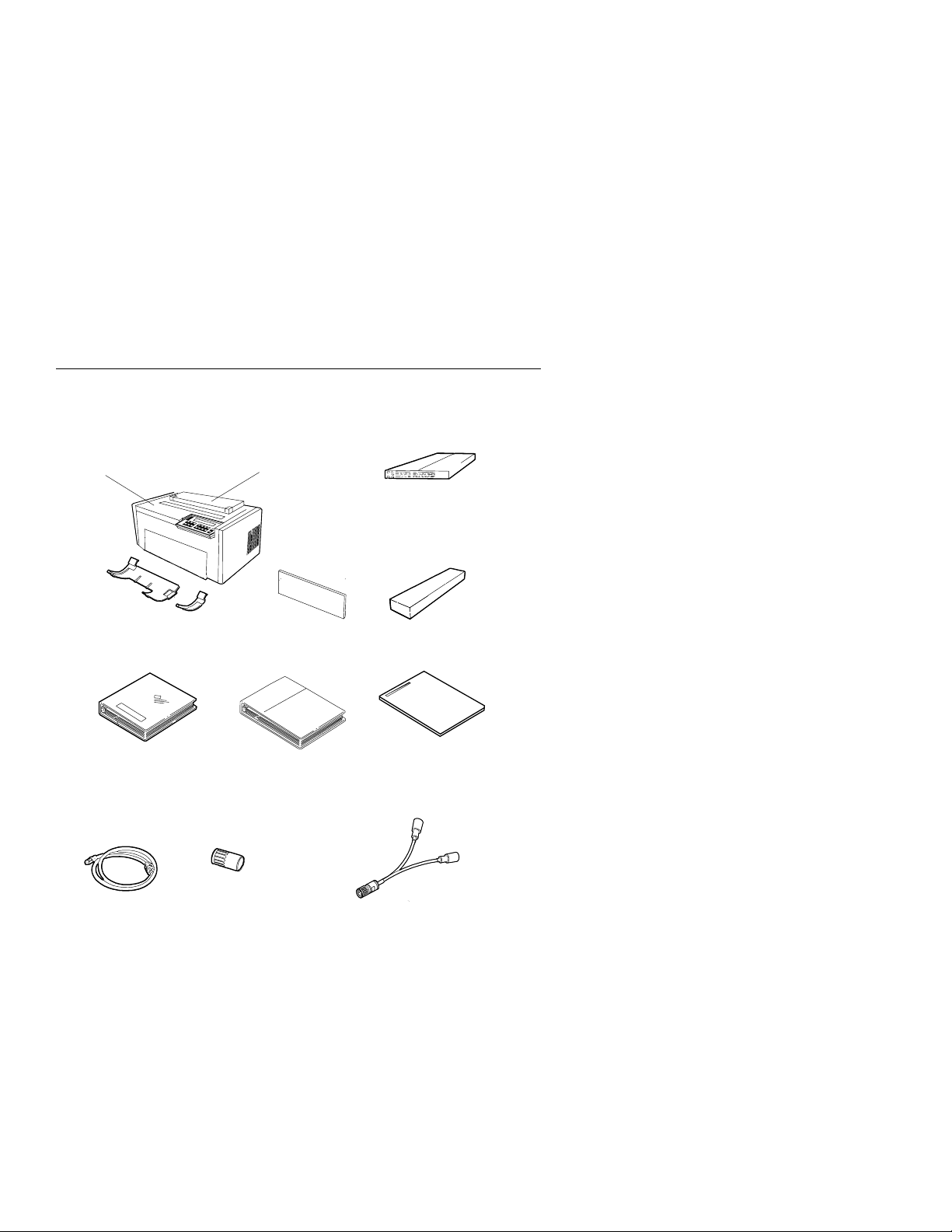
1. Be sure that you have the following items:
Printer
Acoustic Cover
Forms Device
Lower Forms G uides
(F3DeviceOnly)
User's Guide
Operator Panel Instructions
Power Cord
Paper Door
(F3DeviceOnly)
Shield
Maintenance
Manuals
Ribbon Cartridge
Quick Reference Guide
V-Connector
(Twinaxial Attached Printers)
Notes:
a. Contact your place of purchase if any of the items shown
above are missing.
b. The Document Insertion Device (F3) is shipped with a long
and short lower forms guide and a paper door. If you
ordered the F3 forms device, be sure that you find the
guides and paper door and set them aside.
c. You also will have enclosed a V-connector.
1-2 User’s Guide
Page 25
Note: The printer weighs approximately 20.4 kg (45 lb). Do not
lift it by yourself.
2. Place the printer at the workstation (printer stand or table of your
choice). Be sure that you have access to both the front and the
rear of the printer.
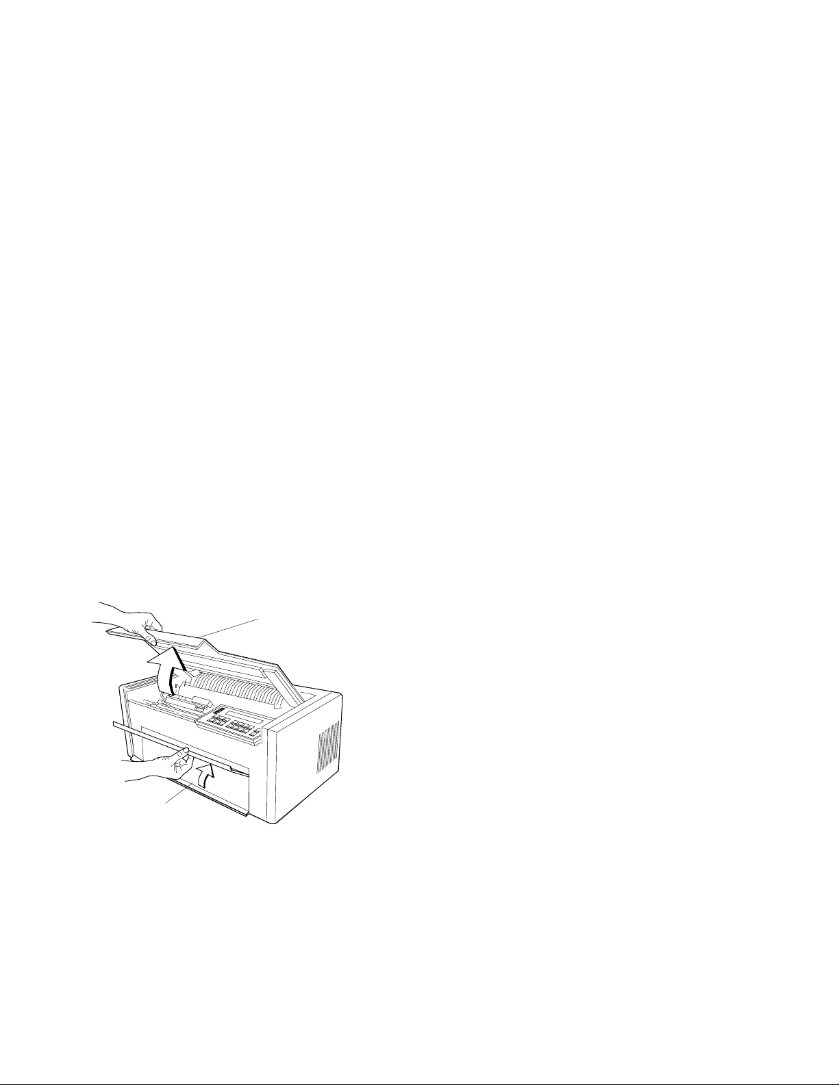
3. Remove the protective film from the access cover window and
discard it.
4. Remove the packaging material, if present, from under the
acoustic door.
5. Open the
access cover
. Then open the front paper door as
follows:
a. Pull the door up until it will not go any higher.
b. Push the door back slightly to lock it in the open position.
Access C over
Paper Door
Chapter 1. Setting Up the 4230 Printer 1-3
Page 26
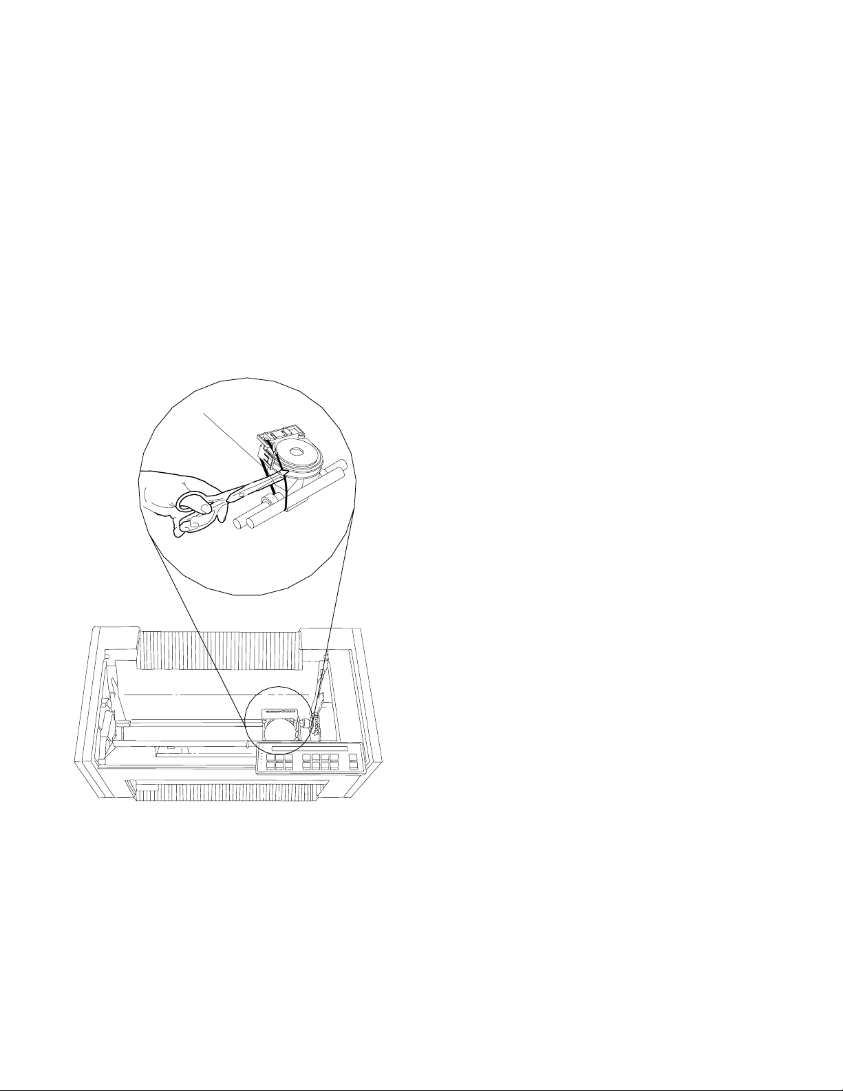
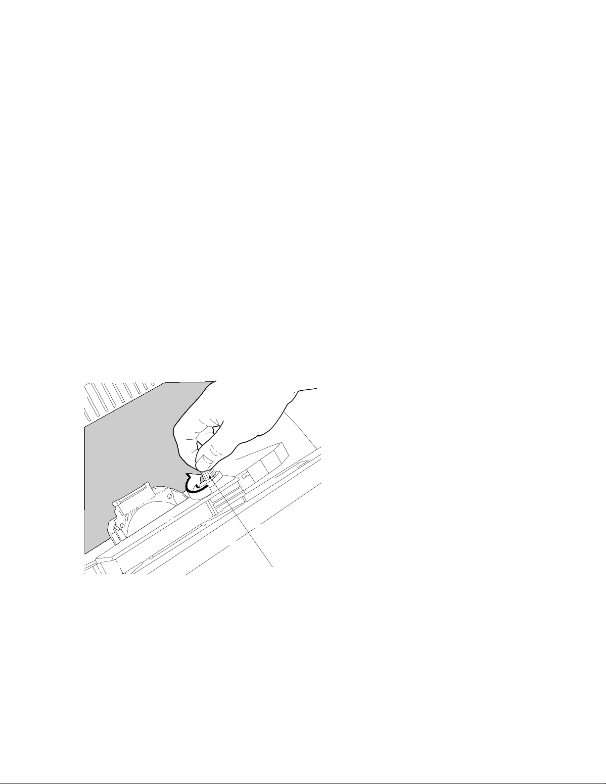
6. Find the
the
print head
the printer.
orange tie
on the right side of the printer to the left of
. Carefully cut the
Orange Tie
orange tie
and remove it from
1-4 User’s Guide
Page 27
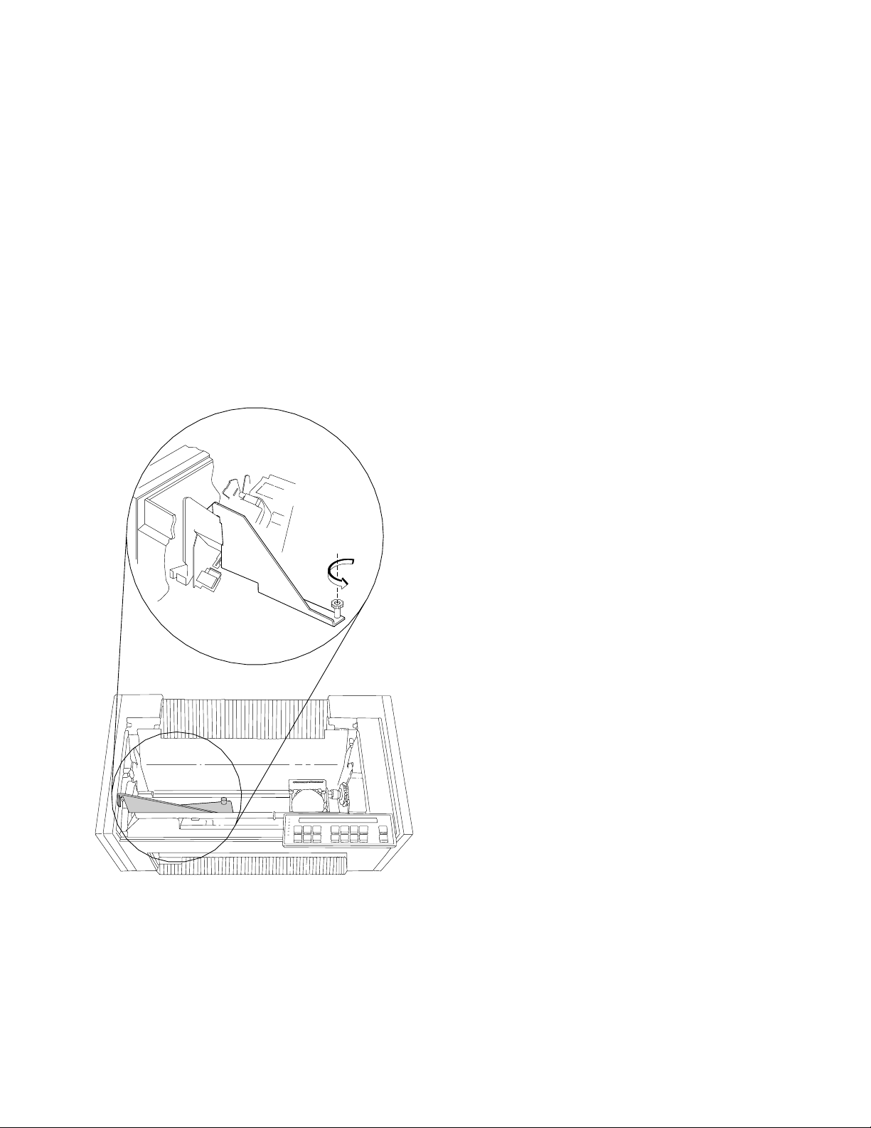
7. Consult the following figure and then find the large
and
orange shipping brace
in the center of the printer. Unscrew
orange knob
the knob and remove the knob and shipping brace from the
printer.
Shipping
Brace
Note: Save the shipping brace in case you relocate the printer.
Chapter 1. Setting Up the 4230 Printer 1-5
Page 28
Installing the Ribbon Cartridge and Guide
The following sections describe preparation, installation, and
verification of the ribbon cartridge.
To install a new ribbon cartridge, follow these steps:
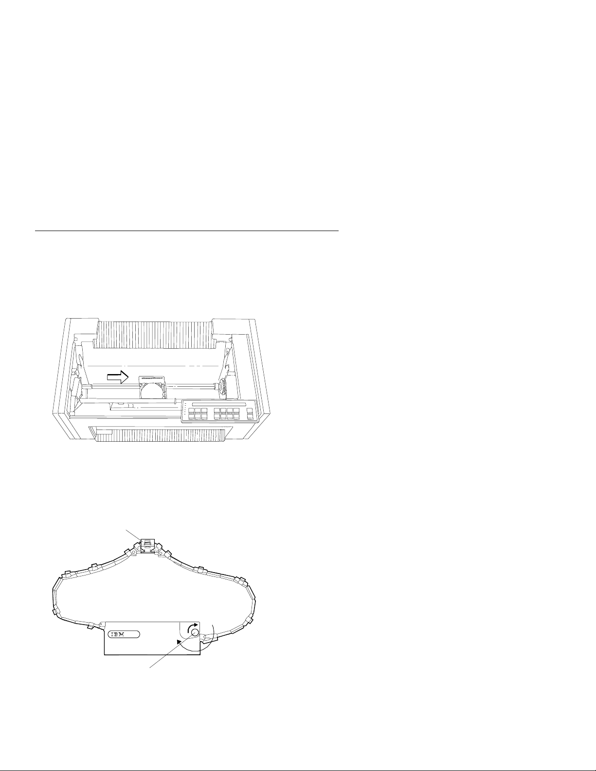
1. Slide the print head to the center of the printer.
2. Remove the ribbon cartridge from the package.
3. Remove the yellow clip from the ribbon.
4. Turn the blue ribbon advance knob clockwise to take up slack
in the ribbon. If the ribbon does not move, contact your place of
purchase and replace the ribbon cartridge.
Remove Yellow Clip
Blue Ribbon Advance Knob
1-6 User’s Guide
Page 29
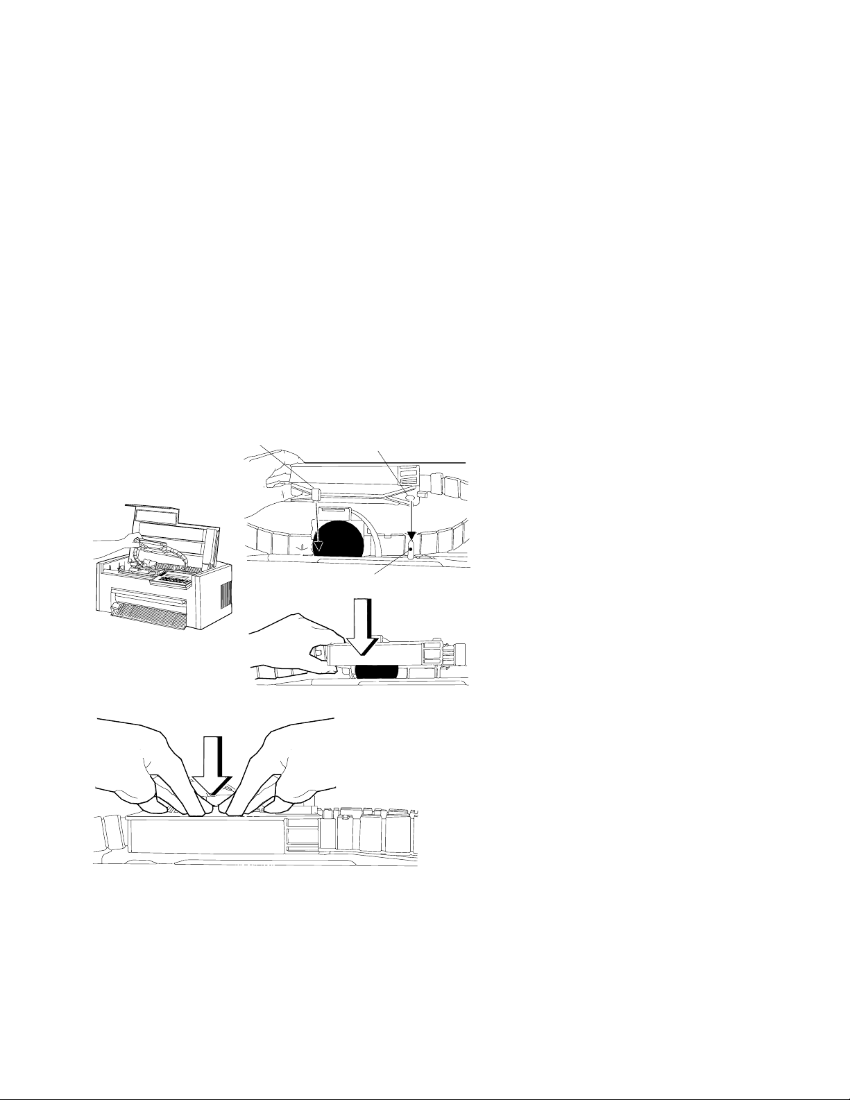
5. Align the blue slotted opening on the bottom of the ribbon
cartridge with the
metal post
. You may need to turn the blue
ribbon advance knob to align the slots. Lower the ribbon
cartridge onto the
metal post
. Be sure that the
plastic tab
bottom of the ribbon cartridge aligns with the hole in the printer
casting.
Tab
Blue Slotted Opening
MetalPost
on the
6. Press the cartridge down firmly to snap it into place.
Chapter 1. Setting Up the 4230 Printer 1-7
Page 30
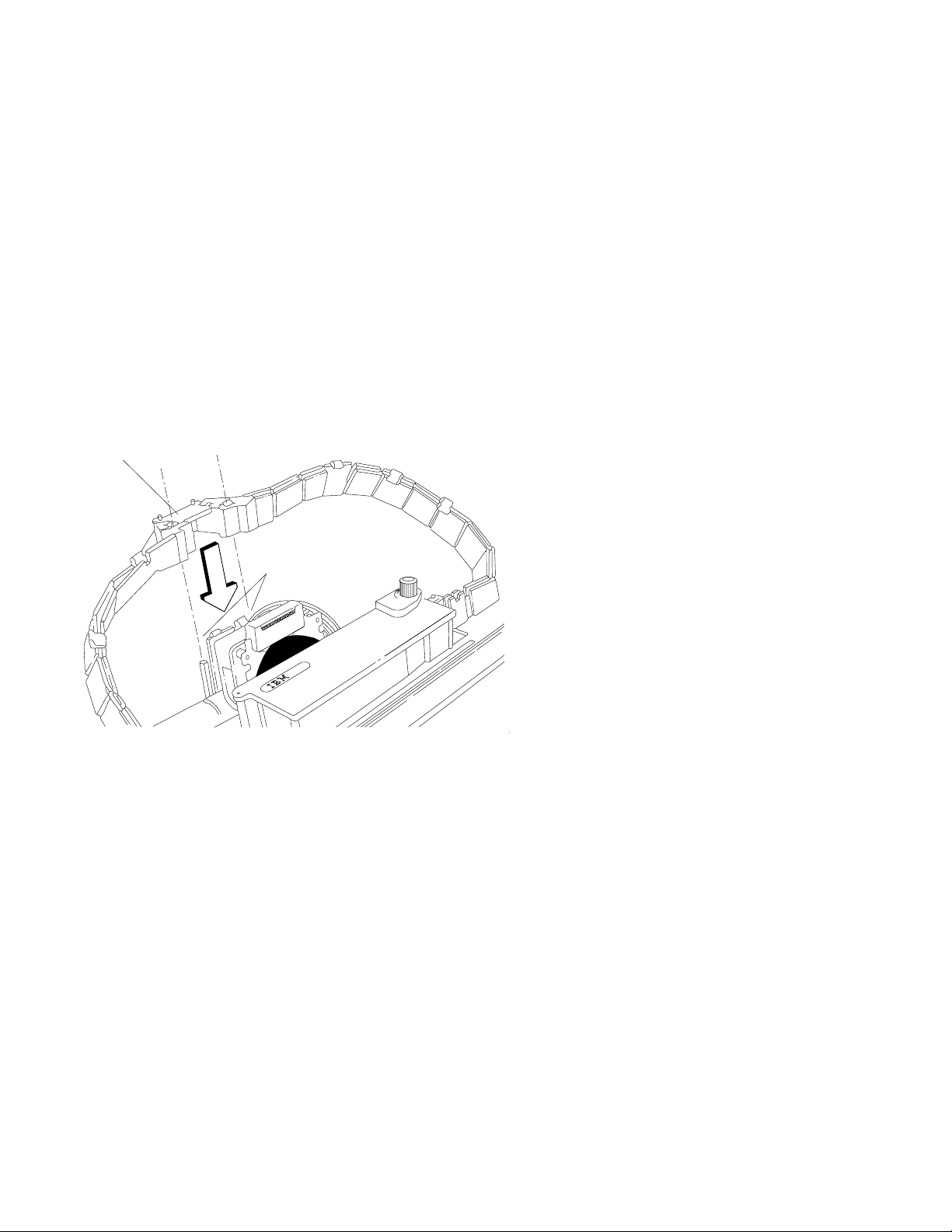
7. Align the holes in the ribbon guide with the
the
print head carrier
. Press the guide all the way down on
ribbon guide posts
the posts until the tops of the posts are even with the top of
the ribbon guide.
Ribbon Guide
Ribbon
Guide Posts
on
1-8 User’s Guide
Page 31
8. To be sure you have installed the ribbon cartridge correctly,
check that:
a. The left side of the ribbon cartridge is securely snapped onto
the printer. The right side fits over the ribbon drive post but
does not latch down.
b. There are no twists or folds in the ribbon.
c. The ribbon is not catching on the print head.
d. The ribbon moves when you turn the blue ribbon advance
knob clockwise. If the ribbon does not move, replace the
ribbon cartridge.
Blue Ribbon Advance Knob
Chapter 1. Setting Up the 4230 Printer 1-9
Page 32

Preparing for Forms Device Installation
To prepare for installing the forms device, follow these steps:
CAUTION:
The construction of this machine provides extra protection
against the risk of electric shock by grounding appropriate
metal parts. The extra protection may not function unless
the power cord is connected to a properly grounded outlet.
This machine has a grounding-type (3-wire) power cord
because grounding is necessary. It is the responsibility of
the customer or the person installing the machine to
connect it to a properly grounded outlet. Seek professional
assistance before using an adapter or extension cord; such
a device could interrupt the grounding circuit.
If this machine is connected to an outlet that has been
incorrectly connected to the building wiring, serious electric
shock could result.
1. Make sure the
power switch
is Off (O). Connect the
power cord
to the rear of the printer. Press firmly to be sure that the plug is
securely seated.
Power Switch
Plug the power cord into the electrical outlet.
1-10 User’s Guide
Page 33

2. If you received your printer without an operator panel template
installed, you must install the template shipped with the printer.
To install the template, do the following:
a. Remove the paper from the back of the template.
b. Press the template into place on the operator panel, as
shown in the following figure.
xxxxx
xxxxx
xxxxxxxxx
xxxxx
xxxxxxxx
xxxx xxxx
xxxx
xxxxx
xxxxxx
xxxx
xxxxx
xxxx
xxxxx
xxxxx
xxxx
xxxxxx
xxxxx
xx x
xx x
xxxx
xxxx
xxxxx
xxxxx
To change the language shown on the operator panel
display, see “Using Printer Setup Parameters” in
IBM 4230
Printer Models 101, 1S2, 201, 2S2, 4S3, and 5S3 Operator
Panel Instructions
.
Chapter 1. Setting Up the 4230 Printer 1-11
Page 34

3. Use the following figures to learn the location of keys and
indicators on the operator panel. Figure 1-1, Figure 1-2,
Figure 1-3 on page 1-13, and Figure 1-4 on page 1-13 show
the operator panel for each model.
Power
Ready
Processing
Micro
Online
Attention
Unit Check
Menu
Quick
Scroll
Micro
Scroll
Darker
Enter
Lighter
Return
Figure 1-1. 4230 Printer Models 101 and 1S2 Operator Panel
Power
Ready
Processing
Micro
Format
Attention
Unit Check
Menu
Quick
Scroll
Micro
Scroll
Darker
Enter
Lighter
Return
Hex
Print
Display
Address
PA1
PA2
Line
Feed
Load/
Eject
Line
Feed
Load/
Eject
Form
Feed
Set Top
of Form
Form
Feed
Set Top
of Form
Start
Stop
Start
Stop
Cancel
Print
Test
Cancel
Print
Test
Figure 1-2. 4230 Printer Models 201 and 2S2 Operator Panel
1-12 User’s Guide
Page 35

Power
Ready
Processing
Micro
Online
Attention
Unit Check
Menu
Quick
Scroll
Micro
Scroll
Darker
Enter
Lighter
Return
Figure 1-3. 4230 Printer Model 4S3 Operator Panel
Power
Ready
Processing
Micro
F or m a t/O n lin e
Attention
Unit Check
Menu
Quick
Scroll
Micro
Scroll
Darker
Enter
Lighter
Return
Hex
Print
Display
In terfa ce
PA1/
Hex
Print
PA2/
Display
In te rfac e
Line
Feed
Load/
Eject
Line
Feed
Load/
Eject
Form
Feed
Set Top
of Form
Form
Feed
SetTop
of Form
Start
Stop
Start
Stop
Cancel
Print
Test
Cancel
Print
Tes t
Figure 1-4. 4230 Printer Model 5S3 Operator Panel
Chapter 1. Setting Up the 4230 Printer 1-13
Page 36
4. Turn the power On (|).
Note: Do not turn the printer power Off (O) during setup unless
instructed to do so.
The printer does the following:
a. All indicators and blocks on the display light, and the alarm
beeps. Then the printer displays
The printer then displays
DIAGNOSTICS IN PROGRESS <A>
b. The print head and ribbon move.
c. The printer displays
Calibrating Printer <A>
Please Wait
and then
DIAGNOSTICS COMPLETE <A>
followed by
ðð1 END OF FORMS
LOAD FORMS
The Attention indicator also blinks and the alarm beeps.
This status code appears because forms have not been
loaded.
1-14 User’s Guide
Page 37

d. Press Stop.
The printer may display
ð9ð COVER/DOOR OPEN
PRINT SPEED REDUCED
and then on
Models 101, 1S2, and 4S3
you may see
ð15 COMMUNICATIONS CHECK
CHECK CABLE
or on
Models 201, 2S2, and 5S3
you may see
ð28 COMMUNICATIONS CHECK
CALL SYSTEM OPERATOR
While on
Models 4S3 and 5S3
(when parallel or serial is the
active interface) you may see
ð29 LINK ERROR
Ignore these messages until you have attached the printer to
your computer. (Press Stop to turn off the alarm, if
necessary.)
5. If the printer operated correctly, go to Step 6 on page 1-17,
otherwise, check the following:
Chapter 1. Setting Up the 4230 Printer 1-15
Page 38

Operator Note
If you turned the power Off (O) and back On (|) in
10 seconds
, the display may be blank or a message may
less than
appear.
If the power-on messages do not appear in your language,
see “Using Printer Setup Parameters” in
IBM 4230 Printer
Models 101, 1S2, 201, 2S2, 4S3, and 5S3 Operator Panel
Instructions
to change the Display Language.
a. Did the printer come on after you turned the power On (|) in
Step 4 on page 1-14?
If
Yes
, go to Step 5b.
If No, perform Steps 5a1 through 5a6.
1) Turn the power Off (O).
2) Unplug the printer power cord from the electrical outlet.
3) Be sure that the power cord is firmly connected to the
rear of the printer.
4) Try another electrical device (such as a lamp) in the
outlet.
5) If the outlet is working, connect the printer to the outlet
again. Return to Step 4 on page 1-14 and try again.
6) If the printer still fails to come on, call your service
representative.
b. Did the printer display a code or message and did the same
code or message remain on the display after approximately
30 seconds?
If
Yes
, go to Appendix B, “Problem Solving,” find the
status code or message the printer displayed, and follow
the instructions.
If No, go to Step 5c on page 1-17.
1-16 User’s Guide
Page 39

c. Did the indicators or display not respond, or did you have an
alarm problem?
If
Yes
, then call for service.
If No, go to Step 6.
6. The shipping box for the forms device has printing on the side to
help you identify what type of forms device you have. Note
which forms device is checked off, then remove the forms device
from the shipping box.
Note: If you have forms device F3, the shipping box also
contains the lower forms guides and F3 paper door.
7. Press Menu. Then press Scroll ↑ or Scroll ↓ until the printer
displays
CONFIGURATION MENU
Printer Setup
8. Press Enter to select this category.
9. Press Scroll ↑ or Scroll ↓ until the printer displays
Printer Setup
Forms Device
10. Press Enter to select this parameter.
11. Press Scroll ↑ or Scroll ↓ until the printer displays the desired
forms device.
12. Press Enter to set the device.
An asterisk (*) appears beside your choice of device.
13. You now need to save this change to the power-on custom set
(Custom Set A), so the printer will have the correct device setting
the next time it is turned on.
a. Press Return twice to get back to the category level of the
Configuration Menu.
Chapter 1. Setting Up the 4230 Printer 1-17
Page 40

CONFIGURATION MENU
Printer Setup
b. Press Scroll ↑ or Scroll ↓ until the printer displays
CONFIGURATION MENU
Configuration Storage
c. Press Enter.
The printer displays
Configuration Storage
Save Current Values
d. Press Enter.
The printer displays
Save Current Values
Custom Set A
e. Press Enter to save the configuration changes.
The printer displays
Save Current Values
Custom Set A Saved
14. Turn the power Off (O).
1-18 User’s Guide
Page 41

15. Slide the print head to the center of the printer.
16. You are now ready to install the forms device. Go to “Selecting
the Forms Device Installation Procedure” on page 1-20.
Chapter 1. Setting Up the 4230 Printer 1-19
Page 42

Selecting the Forms Device Installation Procedure
Select the forms device installation procedure you will use:
Go to “Installing and Using the Continuous Forms Device (F1)”
on page 1-21 to install the F1 forms device.
Go to “Installing and Using the Dual Purpose Forms Device (F2)”
on page 1-55 to install the F2 forms device.
Go to “Installing and Using the Document Insertion Device (F3)”
on page 1-88 to install the F3 forms device.
See “Setting Up Your 4230 Printer with ASF” in
Auto Sheet Feeder General Information
device.
to install the F4 forms
IBM 4230 Printer
1-20 User’s Guide
Page 43
Installing and Using the Continuous Forms Device
(F1)
The following sections describe how to install and use the
Continuous Forms Device (F1).
Note: Make sure that the proper forms device is configured. See
“Preparing for Forms Device Installation” on page 1-10 for the exact
steps.
Installing the Continuous Forms Device (F1)
To install the F1 forms device, follow these steps:
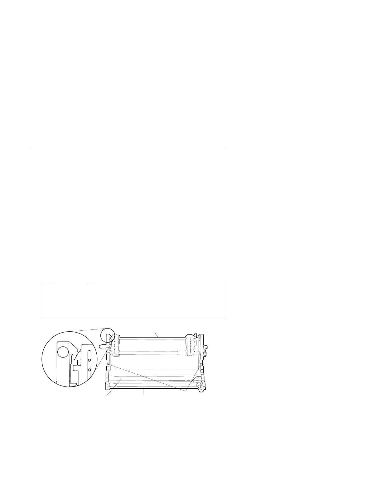
1. Hold the forms device so that the
upper left corner facing you. Note the
clips
; they will be important later.
device number
bottom metal bar
F1 is in the
2. Remove the orange shipping clip, if installed.
Important
The F1 forms device for the 4230 Printer has a circle around
the F1 emblem. Use only these forms devices in the 4230
Printer.
Top of Form s Device
F1
Tensioner Plates
Bottom M etal Bar
C lip s
and the
Chapter 1. Setting Up the 4230 Printer 1-21
Page 44

3. Lower the forms device into the printer behind the
that the
bottom metal bar
enters the printer first. Align the ends
platen rod
so
of the forms device with the slots in the frame. Continue to lower
the forms device until the device rests in the slots of the frame.
Top of
Forms
Device
End of
Device
Platen Rod
End of
Device
Slot in
Frame
Slot in
Frame
4. Look through the front bottom opening in the printer and find the
metal bar
at the bottom of the forms device.
5. Grasp the
metal bar
with BOTH hands and pull firmly toward you
and then upward until both ends LOCK into place.
Metal Bar
Bottom of Forms Device
1-22 User’s Guide
Page 45

6. To be sure that you have installed the forms device correctly,
look at the following figure and compare it to your printer. Check
both the left and right sides. Are the
clips
around the
platen rod
as shown? If so, you installed the forms device correctly. If not,
repeat Steps 3 through 5.
Platen R od
Platen R od
Clip
Chapter 1. Setting Up the 4230 Printer 1-23
Clip
Page 46

Preparing to Load Forms
To prepare to load forms in the F1 forms device, follow these steps:
1. Slide the print head to the far left side of the printer.
2. Loosen the blue forms tension knob by turning it
counterclockwise, and then move the blue forms tension knob
towards the bottom of the printer until you see the* below the
number 1.
Blue Forms
Tension Knob
Note: Moving the blue forms tension knob to the* position
lets you load forms.
3. Unlock the blue locking lever on the
right tractor
. Slide the
tractor to the extreme right.
Blue Locking Lever
1-24 User’s Guide
Page 47

4. Open both of the blue tractor doors.
Blue Tractor Doors
5. Get continuous forms paper that is at least 203.2 mm (8 in.)
wide.
Chapter 1. Setting Up the 4230 Printer 1-25
Page 48

Loading Forms in the F1 Forms Device
To load forms in the F1 forms device, follow these steps:
1. Feed the form into the bottom front of the printer. Be sure that
the form goes under the blue forms guide/forms sensor and
between the tension plates. See the figure on page 1-21 for
help in locating the tension plates.
Blue Forms Guide/
Forms Sensor
1-26 User’s Guide
Page 49
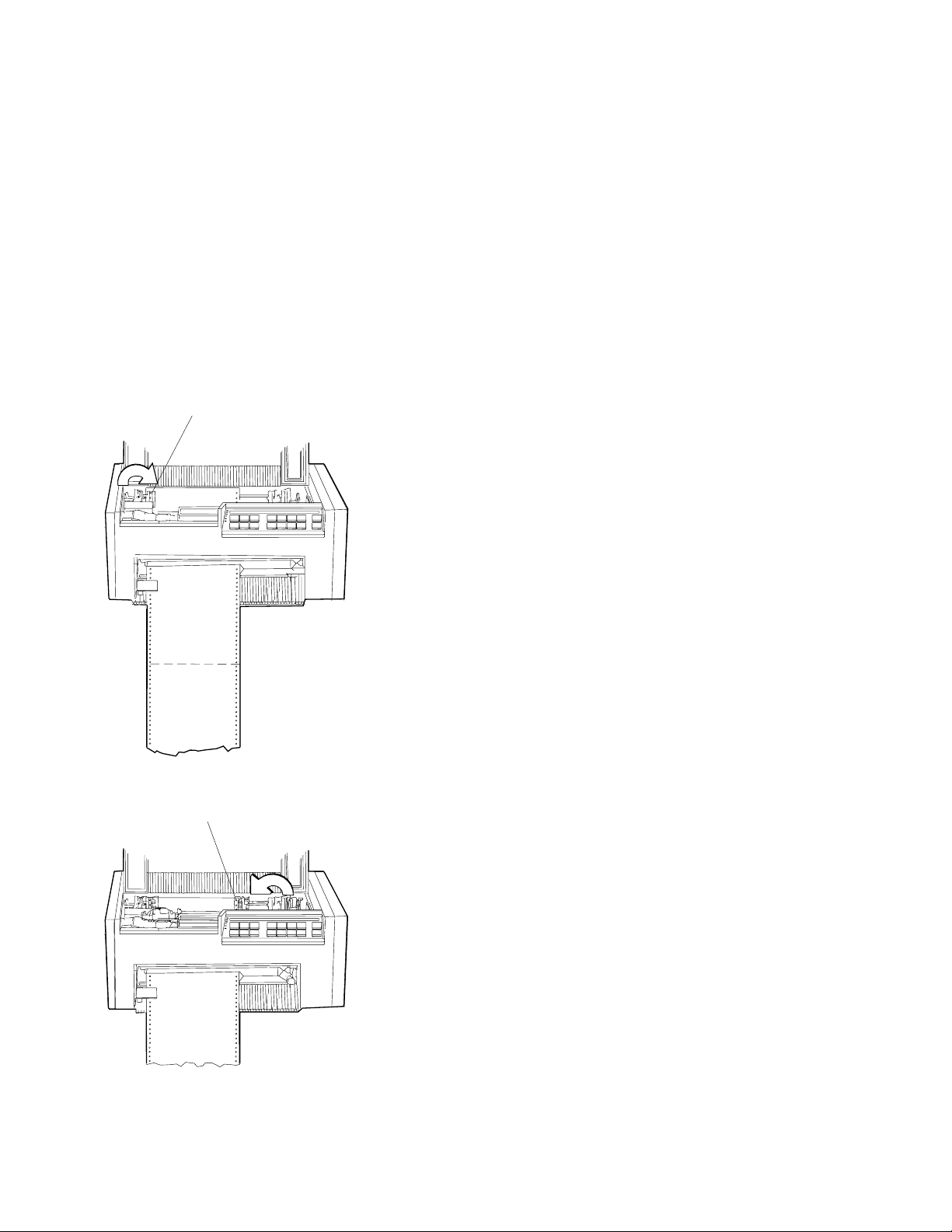
2. Align and put the left paper holes of the form over the
tractor pins
3. Move the
on the
. Close the left blue tractor door.
Blue Tractor Door
right tractor
right tractor pins
Tractor P ins
until the right paper holes of the form fit
. Be sure that the forms are straight.
left
Chapter 1. Setting Up the 4230 Printer 1-27
Page 50

4. Close the right blue tractor door. Hold the tractor in place and
lock the blue locking lever.
Note: If necessary, unlock the tractor and adjust it so that the
forms are not buckled or stretched too tightly.
Blue Tractor
Door
Blue Locking Leve r
5. Close the access cover. Then close the paper door by pulling it
out and pushing it down until it latches.
1-28 User’s Guide
Page 51

6. To align the top of form position, follow these steps:
a. Turn the power On (|) and wait for the power-on sequence to
complete (see “Power-On Test” on page 3-4).
b. Press Stop.
The printer displays
NOT READY <A>
and then on
Models 101, 1S2, and 4S3
you may see
ð15 COMMUNICATIONS CHECK
CHECK CABLE
or on
Models 201, 2S2, and 5S3
you may see
ð28 COMMUNICATIONS CHECK
CALL SYSTEM OPERATOR
While on
Models 4S3 and 5S3
(when parallel or serial is the
active interface) you may see
ð29 LINK ERROR
Ignore these messages until you have attached the printer to
your computer. (Press Stop to turn off the alarm, if
necessary.)
Chapter 1. Setting Up the 4230 Printer 1-29
Page 52

c. Press Micro ↑, Micro ↓, or Line Feed to move the form so
that the position of the first line you want to print is in the
center of the flat platen rod surface.
Platen Rod
abcdef
Platen Rod
First Print Line
Platen Rod Surface
d. If you pressed Micro ↓, you might have slack in the forms.
Pull lightly downward on the forms at the bottom of the
printer to remove the slack.
e. Press Set Top of Form to establish the first print line.
Note: The Set Top of Form key establishes the first line at
which printing is to start on each form. The alarm beeps
each time you press the Set Top of Form key, and the
printer displays
TOP OF FORM SET
1-30 User’s Guide
Page 53

7. To adjust the forms tension:
a. Open the front paper door as follows:
1) Pull the door up until it will not go any higher.
2) Push the door back slightly to lock it in the open position.
Paper Door
b. Move the blue forms tension knob upward to the number
of form copies you are using. Make sure you do not unlatch
the forms device. For example, if you are using single-part
forms, set the lever to 1. If you are using two-part forms, set
the lever to 2.
Tighten the blue forms tension knob by turning it
clockwise. Close the paper door by pulling it out and
pushing it down until it latches.
Blue Forms
Tension K nob
Chapter 1. Setting Up the 4230 Printer 1-31
Page 54

c. Press Start.
The printer displays
READY <A>
and then on
Models 101, 1S2, and 4S3
you may see
ð15 COMMUNICATIONS CHECK
CHECK CABLE
or on
Models 201, 2S2, and 5S3
you may see
ð28 COMMUNICATIONS CHECK
CALL SYSTEM OPERATOR
While on
Models 4S3 and 5S3
(when parallel or serial is the
active interface) you may see
ð29 LINK ERROR
Ignore these messages until you have attached the printer to
your computer. (Press Stop to turn off the alarm, if
necessary.)
1-32 User’s Guide
Page 55

Using the Printer Verification Test for the F1 Forms
Device
To run the printer verification test, follow these steps:
1. Turn the power On (|) if not already on.
2. Wait until the printer displays
READY <A>
3. Press Stop.
The printer displays
NOT READY <A>
and then on
ð15 COMMUNICATIONS CHECK
CHECK CABLE
or on
Models 201, 2S2, and 5S3
ð28 COMMUNICATIONS CHECK
While on
active interface) you may see
ð29 LINK ERROR
Ignore these messages until you have attached the printer to
your computer. (Press Stop to turn off the alarm, if necessary.)
4. Press Test.
Models 101, 1S2, and 4S3
CALL SYSTEM OPERATOR
Models 4S3 and 5S3
you may see
you may see
(when parallel or serial is the
Chapter 1. Setting Up the 4230 Printer 1-33
Page 56

The printer displays
OPERATOR PRINT TESTS
Printer Demonstration
5. Press Scroll ↑ or Scroll ↓ until the printer displays
OPERATOR PRINT TESTS
Printer Verification
6. Press Enter or Start to print this test. The Ready indicator
comes on and printing begins.
7. Wait for the printer to stop printing and the Ready indicator to go
off.
8. Press Form Feed until you can remove the printout.
The lines numbered 1 through 9 should print as shown on the
sample printout on page 1-35, and the remainder of the printout
should be clear and readable.
1-34 User’s Guide
Page 57

Chapter 1. Setting Up the 4230 Printer 1-35
Page 58

9. Compare your printout with the sample printout.
Did the lines print and is the remainder of the printout clear and
readable?
If
YES
, go to Step 10.
If NO, do the following:
a. If any of the following items are not installed correctly, the
printer can experience forms jamming, ribbon jamming, or an
incorrect printer verification printout:
Forms device
Ribbon cartridge
Forms.
Repeat the Setup Instructions from page 1-6 if you suspect a
ribbon, forms, or forms device installation problem.
b. Be sure that enough forms are loaded and press Enter or
Start to get another printout.
c. If the second printout is not similar to the sample printout, go
to Appendix B, “Problem Solving.”
d. Once you get a good printout, go to Step 10.
10. Turn the power Off (O).
Power Switch
1-36 User’s Guide
Page 59

Setup and Checkout Complete
You have completed a simple setup and checkout of the printer.
IBM recommends that you print your power-on custom set
(Custom Set A) factory defaults and save this printout for future
reference. You are ready to attach the printer to your computer.
Go to Chapter 2, “Attaching the 4230 Printer to Your Computer”
on page 2-1.
Note: See pages 1-38 through 1-53 for making adjustments,
unloading forms, and removing the forms device.
Chapter 1. Setting Up the 4230 Printer 1-37
Page 60

Adjusting the Print Quality
After the printer prints a few lines, press Stop and verify that the
print quality is satisfactory. Good print quality includes:
Clear, legible print
Satisfactory darkness or lightness of output.
It is up to you to decide if the print quality is satisfactory.
Adjustments you can make that affect print quality include:
Tractor Tension
Incorrect tension on the right tractor can cause the paper holes
on the forms to tear, wrinkle, or jam in the printer. To adjust the
tractor tension, see “Adjusting the Tractor Tension” on
page 1-39.
Forms Thickness Setting
This setting can affect the darkness or lightness of output.
The printer will normally sense the forms thickness and adjust
itself automatically. However, if this setting is not correct, it can
be adjusted. To adjust the forms thickness, see “Adjusting the
Forms Thickness Setting” on page 1-40.
Note: The Automatic Forms Thickness Adjustment (AFTA)
mechanism automatically measures the forms thickness and
adjusts the gap from the print head to the platen rod based on
the measured value. See “Automatic Forms Thickness
Adjustment (AFTA)” on page 3-8 for information on how the
4230 Printer sets the forms thickness.
Forms Tension
Incorrect tension on the forms can cause forms to tear, wrinkle,
or buckle and can affect the appearance of the output. To adjust
the forms tension, see “Adjusting the Forms Tension” on
page 1-42.
Left Margin and Top of Form Position
The adjustment of the first print position can affect the
appearance of the output, especially if you are using preprinted
forms. To adjust the position of the first print character, see
“Adjusting the Left Margin” on page 1-44. To adjust the position
1-38 User’s Guide
Page 61

of the first print line, see “Adjusting the Top of Form Position” on
page 1-46.
Print Alignment
This adjustment can affect the character formation and dot
mixing on those characters that are printed with two passes of
the print mechanism. To adjust the print alignment, see
“Adjusting the Print Alignment” on page 1-48.
Adjusting the Tractor Tension
The tractor tension adjustment controls the amount of buckle the
forms have when they are loaded in the printer. Since the left tractor
does not move, you make this adjustment by moving the right tractor.
The ideal adjustment is to center the right and left paper holes of the
forms on the tractor pins without stretching or tearing the holes.
To adjust the tractor tension on the F1 forms device, follow these
steps:
1. Feed several forms through the printer.
2. Observe the left and right paper holes of the forms:
If the paper holes are stretched or torn on the outside edges,
the tractor tension is too tight (not enough buckle in the
forms).
If the forms twist or wrinkle as they move through the printer,
the tractor tension is too loose (too much buckle in the
forms).
3. Adjust the right tractor as necessary:
Unlock and move the tractor toward the left side of the
printer to loosen the tension on the forms.
Unlock and move the tractor toward the right side of the
printer to tighten the tension on the forms.
Chapter 1. Setting Up the 4230 Printer 1-39
Page 62

Left Margin
Right Margin
Correct
Left Margin
Right Margin
Incorrect
4. Lock the tractor.
Adjusting the Forms Thickness Setting
To adjust the lightness or darkness of the print, you must increase or
decrease the gap between the print head and the platen rod. This
distance is automatically set for you by the Automatic Forms
Thickness Adjustment (AFTA), but you can make corrections to the
distance if the print output is not as you desire. It is up to you to
decide if the print is dark (or light) enough to meet your
requirements.
To adjust the forms thickness setting with the F1 forms device, follow
these steps:
1. The forms thickness setting must be adjusted when the printer is
printing or has printed and is
ready
. Press Start, if needed, to
have the printer display
READY <A>
2. To make the print darker, press Darker.
The printer displays
LIGHT |wwwwwwwwwwww-------| DARK
The print head moves closer to the paper, and the print becomes
darker.
1-40 User’s Guide
Page 63

Note: The print may not get darker if the ribbon is worn or if
there is a problem with the print head.
3. To make the print lighter, press Lighter.
The printer displays
LIGHT |wwwwwwww-----------| DARK
The print head moves farther away from the paper, and the print
becomes lighter.
4. When you release the key, the printer automatically saves the
current value.
Note: The J’s indicate the position of the print head relative to the
limits.
As long as you press Darker or Lighter, the printer displays an
increasing amount of darkness or lightness until one of the limits of
the gap is reached. The printer displays either
LIGHT |wwwwwwwwwwwwwwwwwww| DARK
DARKNESS LIMIT REACHED
or
LIGHT |w------------------| DARK
LIGHTNESS LIMIT REACHED
As you adjust the gap, you may also see the printer display
LIGHT |wwwwwwwwww---------| DARK
DEFAULT DARKNESS
This message tells you that the forms thickness setting is at the
automatically set value.
Chapter 1. Setting Up the 4230 Printer 1-41
Page 64

See “Understanding the Operator Panel” in
101, 1S2, 201, 2S2, 4S3, and 5S3 Operator Panel Instructions
IBM 4230 Printer Models
for
more information on this setting.
Adjusting the Forms Tension
The forms tension lever controls the tension on the forms. The blue
forms tension knob lets you adjust the setting of the forms tension
lever. The forms tensioner is a metal plate with a row of metal
fingers that applies tension to the form according to the setting of the
forms tension lever.
Settings range from* to 6. The * setting puts no tension on the
form and allows forms to pass freely while loading. The 1 setting
puts the least amount of tension on the form. Settings 2 through 6
vary the amount of tension on the form and approximately relate to
the number of sheets in the form you use. Set the tension lever to
the number of sheets in the form being used.
Note: Higher numbers are toward the top and lower numbers are
toward the bottom of the printer.
When you adjust the forms tension, be sure that the forms are not
held too tightly or too loosely. If too much tension is on the forms,
the forms can tear, the paper holes of the form can stretch, and
forms can jam. If too little tension is on the forms, the forms can
wrinkle or buckle, causing the forms to jam.
Blue Forms
Tension Knob
1-42 User’s Guide
Page 65

Decreasing Forms Tension:
To decrease tension on the forms,
follow these steps:
1. Loosen the blue forms tension knob by rotating the knob
counterclockwise.
2. Move the knob to a lower number setting.
For example, if the knob was set at 3, move the knob to 2.
3. Tighten the blue forms tension knob by rotating the knob
clockwise. Be sure to avoid unlatching the F1 forms device
when adjusting the forms tension.
4. Press Start to print.
5. Observe the forms.
If the form paper holes are still tearing or stretching, press Stop
and repeat Steps 1 through 5 of this procedure.
If the forms are buckling, there is too little tension on the forms.
If the tension is satisfactory, continue to print.
Increasing Forms Tension:
To increase tension on the forms,
follow these steps:
1. Loosen the blue forms tension knob by rotating the knob
counterclockwise.
2. Move the knob to a higher number setting.
For example, if the knob was set at 2, move the knob to 3.
3. Tighten the blue forms tension knob by rotating the knob
clockwise. Be sure to avoid unlatching the F1 forms device
when adjusting the forms tension.
4. Press Start to print.
5. Observe the forms.
If the forms are still buckling, press Stop and repeat Steps 1
through 5 of this procedure.
If the forms are tearing or jamming, there is too much tension on
the forms.
If the tension is satisfactory, continue to print.
Chapter 1. Setting Up the 4230 Printer 1-43
Page 66

Adjusting the Left Margin
You can print a single line of text to help in setting the left margin
position using the Left Margin Alignment Test. You can also change
the current left margin position using this test.
You can set the left margin position from 1 to 66 units (where each
| unit is 0.686 mm [0.027 in.]). The factory default setting is 10. The
| margin is measured starting at 1.27 mm (0.05 in.) from the center of
the tractor pins for continuous forms and the left edge of a cut form.
To align the left margin position, follow these steps:
1. If the printer is
ready
, press Stop.
The printer displays
NOT READY <A>
2. Enter the Operator Print Tests by pressing Test.
The printer displays
OPERATOR PRINT TESTS
Printer Demonstration
3. Press Scroll ↑ or Scroll ↓ until the printer displays
OPERATOR PRINT TESTS
Left Margin Alignment
4. Press Enter or Start to begin the test. The printer displays
Left Margin Position
\ xxx
where
xxx
is the current value of the left margin position.
1-44 User’s Guide
Page 67

The printer also prints a single line of H’s.
5. If the H’s do not start where you want your left margin, press
Scroll ↑ or Scroll ↓ until the printer displays the desired value
for the left margin position.
6. Press Enter.
An asterisk (*) appears in front of the selected value. The
forms advance one line and the row of H’s prints again. This
value is now the current left margin position.
7. Repeat Steps 5 and 6 until the left margin is correctly positioned.
(You can press Line Feed or Form Feed to move the forms
between printing the rows of H’s.)
8. Press Stop or Cancel Print to exit the test.
Note: If you want the new left margin position saved when you
turn off the printer, you must save it in a Custom Set.
See “Storing Configuration Parameters” in
IBM 4230
Printer Models 101, 1S2, 201, 2S2, 4S3, and 5S3
Operator Panel Instructions
for information on saving
configurations.
You may also adjust the left margin position without
printing the row of H’s by changing the Left Margin
Position in the Configuration Menu. (See “Using Print
Format and Quality Parameters” in
IBM 4230 Printer
Models 101, 1S2, 201, 2S2, 4S3, and 5S3 Operator
Panel Instructions
Chapter 1. Setting Up the 4230 Printer 1-45
.)
Page 68

Adjusting the Top of Form Position
The Micro ↑ and Micro ↓ keys control fine vertical movement. Each
time you press these keys, the printer moves the form in 0.355 mm
(0.014 in.) increments.
Open the access cover. Then open the front paper door as follows:
1. Pull the door up until it will not go any higher.
2. Push the door back slightly to lock it in the open position.
Access Cover
Paper Door
Next load forms, if necessary (see “Loading Forms in the F1 Forms
Device” on page 1-26 for more information). Complete the following
steps to make fine vertical adjustments to the top of form position.
To set the top of form position, follow these steps:
1. Press Stop.
The printer displays
NOT READY <A>
1-46 User’s Guide
Page 69

2. If the first print line is not where you want it to be, press Micro ↑,
Micro ↓, or Line Feed until it reaches the desired line.
Note: If you need to adjust the paper downward, adjust at least
five steps beyond where you want the top of form position; then
make your final adjustment in the up direction. You can also use
the Top of Form Alignment Test (see “Top of Form Alignment” on
page 5-4) to print a line of characters to determine more
accurately where you have set the top of form position.
3. When the form is in the correct position, press Set Top of Form.
The alarm beeps and the printer displays
TOP OF FORM SET
4. Advance the form by pressing Form Feed, and decide if the form
is on the desired line. If necessary, repeat Steps 1 through 4 of
this procedure until the first print line is correctly aligned.
Chapter 1. Setting Up the 4230 Printer 1-47
Page 70

Adjusting the Print Alignment
You can adjust dot registration and print quality for characters
created using bidirectional printing. The bidirectional alignment may
need periodic adjustment to maintain print quality.
To change the bidirectional alignment, follow these steps:
1. If the printer is
ready
, press Stop.
The printer displays
NOT READY <A>
2. Press Test.
The printer displays
OPERATOR PRINT TESTS
Printer Demonstration
3. Press Scroll ↓ or Scroll ↑ until the printer displays
OPERATOR PRINT TESTS
Bidirectional Adjustment
4. Press Enter or Start to print this test.
The Ready indicator goes on and printing begins. The test
prints samples using alignment values higher and lower than the
default value. The print sample using the default value is
indicated with an asterisk (*). The alignment printout is
complete when the Ready indicator goes off.
1-48 User’s Guide
Page 71

The printer displays
Bidirectional Adjustment
\
Chapter 1. Setting Up the 4230 Printer 1-49
Page 72

5. If the default value does not give the best print sample, press
Scroll ↓ or Scroll ↑ until the printer displays the same number of
arrows that were printed beside the
best
print sample line. Press
Enter to set this as the new default value. The printer then
prints another line to demonstrate the new default value, and the
test is complete.
or
Press Stop to end the test without changing anything and return
to the Operator Print Tests menu.
or
Press Cancel Print to end the test, exit test mode, perform a
partial reset, and have the printer display
READY <A>
Note: See Chapter 5, “Using the Operator Print Tests” for more
information.
1-50 User’s Guide
Page 73

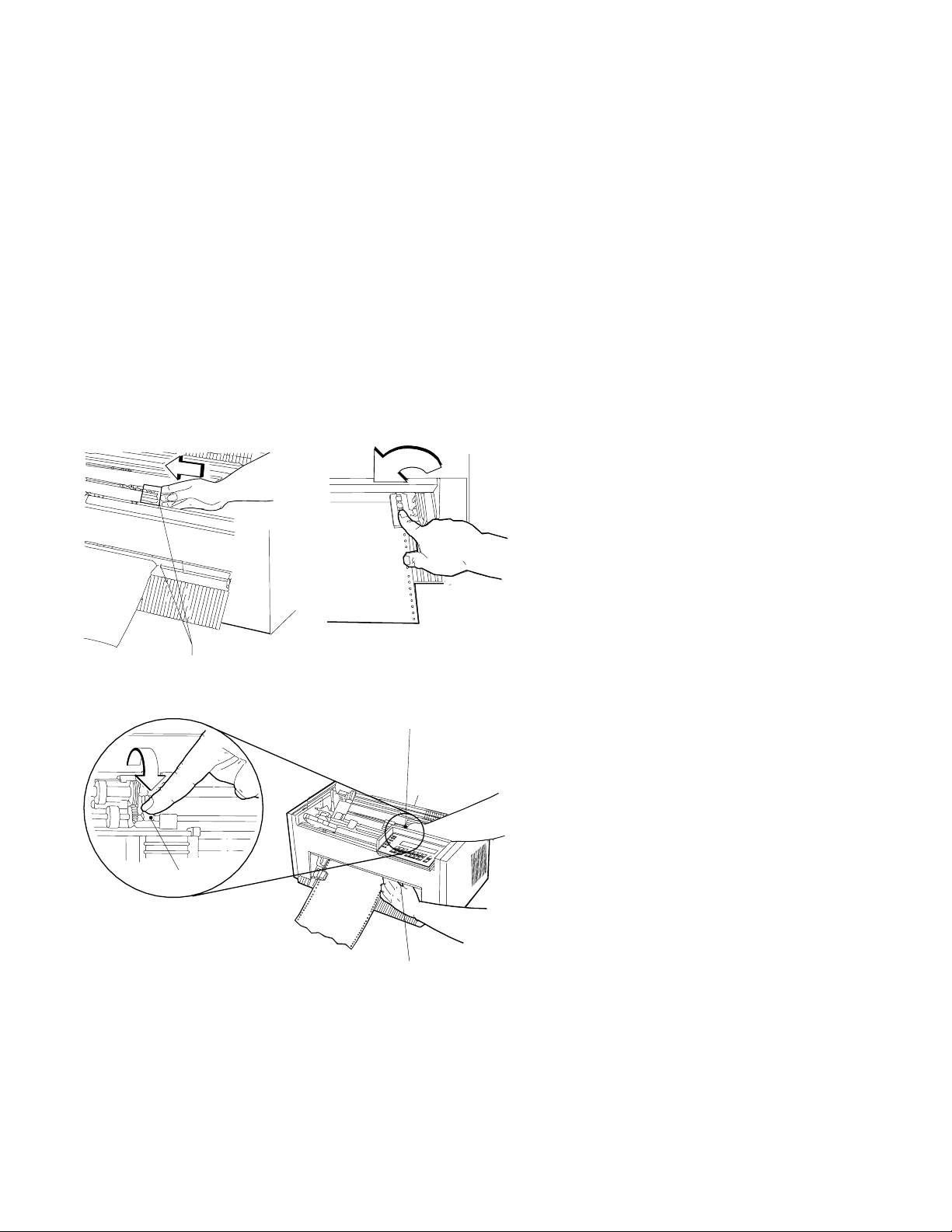
Unloading Forms
To unload forms from the F1 forms device, follow these steps:
1. Press Stop.
The printer displays
NOT READY <A>
2. Open the acoustic cover.
3. Grasp the form below the printer and tear along the perforation.
4. Press Form Feed as many times as needed to advance and
remove the remaining form or forms.
Chapter 1. Setting Up the 4230 Printer 1-51
Page 74
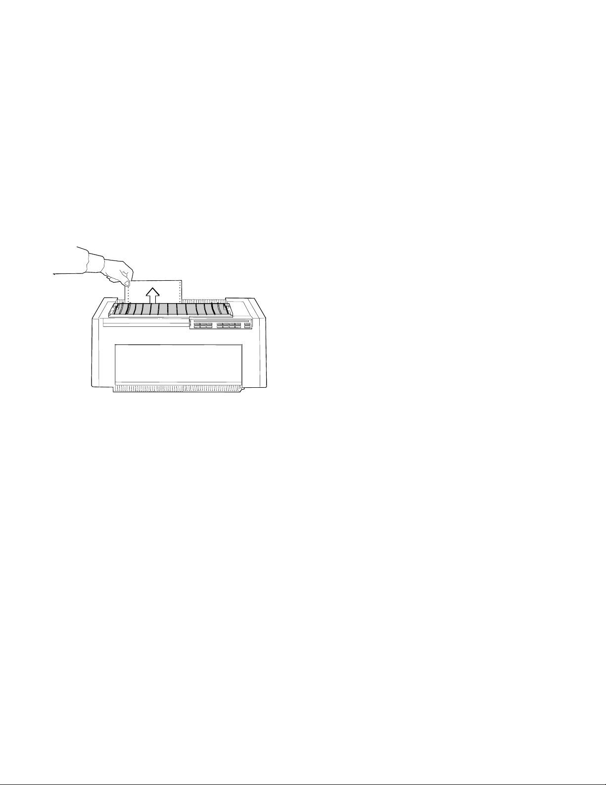
5. Remove the form or forms from the top of the printer.
Warning: Do not remove forms by pulling them out from the
bottom. Damage to the forms device can result.
1-52 User’s Guide
Page 75

Removing the Continuous Forms Device (F1)
Note: If you are removing this forms device to install a different
forms device, make sure you change the selected forms device in
the Configuration Menu.
To remove the F1 forms device, follow these steps:
1. If forms are in the printer, unload them (see “Unloading Forms”
on page 1-51); then continue with Step 2 of this procedure.
2. Turn the power Off (O).
3. Open the access cover. Then open the front paper door as
follows:
a. Pull the door up until it will not go any higher.
b. Push the door back slightly to lock it in the open position.
Access C over
Paper Door
Chapter 1. Setting Up the 4230 Printer 1-53
Page 76

4. Push the metal bar at the bottom of the device toward the rear of
the printer until the forms device unlocks.
Metal Bar
Bottom of Forms Device
5. Grasp the top of the forms device and lift it out.
Top of
Forms
Device
Platen Rod
1-54 User’s Guide
Page 77

Installing and Using the Dual Purpose Forms Device
(F2)
The following sections describe how to install and use the Dual
Purpose Forms Device (F2).
Note: Make sure that the proper forms device is configured. See
“Preparing for Forms Device Installation” on page 1-10 for the exact
steps.
Installing the Dual Purpose Forms Device (F2)
To install the F2 forms device, follow these steps:
1. Hold the forms device so that the
upper left corner facing you. Note the bottom
clips
; they will be important later.
device number
metal bar
F2 is in the
Important
The F2 forms device for the 4230 Printer has a box around
the F2 emblem. Use only these forms devices in the 4230
Printer.
Tear Bar
Top of F o rm s D evice
B o tto m M e tal B a r
C lip s
and the
Chapter 1. Setting Up the 4230 Printer 1-55
Page 78

2. Unlock the right blue locking lever and move the right tractor
assembly to the extreme right.
Tear Bar
Blue S liding
Guides
Top of Forms Device
Bottom Metal Bar
Blue Locking Lever
Right Tractor Assembly
3. Lower the forms device into the printer behind the
platen rod
Be sure that F2 is in the upper left corner facing you and the
blue tractor doors at the bottom of the device enter the printer
first. Align the ends of the device with the slots in the frame.
Continue to lower the device until the ends of the device rest in
the slots of the frame.
Top of
Forms
Device
End of
Device
Platen Rod
End of
Device
Slot in
Frame
Slot in
Frame
.
1-56 User’s Guide
Page 79

4. Look through the front bottom opening in the printer and find the
metal bar
at the bottom of the forms device.
5. Grasp the
metal bar
with BOTH hands and pull firmly toward you
and then upward until both ends LOCK into place.
MetalBar
Bottom of Forms Device
Chapter 1. Setting Up the 4230 Printer 1-57
Page 80

6. To be sure that you have installed the forms device correctly,
look at the following figure and compare it to your printer. Check
both the left and right sides. Are the
clips
around the
platen rod
as shown? If so, you installed the forms device correctly. If not,
repeat Steps 3 on page 1-56 through 5 on page 1-57.
Platen Rod
Clip
Platen Rod
Clip
1-58 User’s Guide
Page 81

Preparing to Load Forms
To prepare to load forms in the F2 forms device, follow these steps:
1. Slide the print head to the far left side of the printer.
2. Open both of the blue tractor doors.
Blue Tractor Doors
3. Get continuous forms paper that is at least 203.2 mm (8 in.)
wide.
Chapter 1. Setting Up the 4230 Printer 1-59
Page 82

Loading Forms in the F2 Forms Device
To load forms in the F2 forms device, follow these steps:
1. Turn the power On (|) (see “Power-On Test” on page 3-4).
2. Wait until the printer displays
ðð1 END OF FORMS
LOAD FORMS
3. Press Stop.
The printer displays
NOT READY <A>
and then on
ð15 COMMUNICATIONS CHECK
CHECK CABLE
or on
Models 201, 2S2, and 5S3
ð28 COMMUNICATIONS CHECK
While on
active interface) you may see
ð29 LINK ERROR
Ignore these messages until you have attached the printer to
your computer. (Press Stop to turn off the alarm, if necessary.)
Models 101, 1S2, and 4S3
CALL SYSTEM OPERATOR
Models 4S3 and 5S3
you may see
you may see
(when parallel or serial is the
1-60 User’s Guide
Page 83

4. Feed the form into the printer until the paper is on at least two
tractor pins on each side. Be sure that the form goes under the
blue forms guide/forms sensor.
Blue Forms Guide/
Form s Sensor
5. Put the
left paper holes
blue tractor door.
over the
Blue Tractor Door
left tractor pins
. Close the left
Chapter 1. Setting Up the 4230 Printer 1-61
Page 84
6. Move the right tractor assembly and blue sliding guides until
the right paper holes of the form fit on the
right tractor pins
sure that the forms are straight. Close the right blue tractor
door.
Right Tractor Assem bly
.Be
7. Hold the
right tractor
Blue Locking
Lever
in place and lock the blue locking lever.
Blue Locking Lever
Right Tractor
Note: If necessary, unlock the tractor and adjust it so that the
forms are not buckled or stretched too tightly. Be sure that you
lock the locking lever when you are finished adjusting.
1-62 User’s Guide
Page 85

8. Evenly space the blue sliding guides between the tractors.
S lid in g G u id e s
9. Perform an autoload by pressing Load/Eject, and the form will
automatically move to the load position. For more information,
see “Adjusting the Load Position” on page 1-81.
Note: You can adjust the load position by using the
Micro ↑, Micro ↓, or Line Feed keys. If you plan to use the
Document on Demand feature, see “Adjusting the Tear-off
Position” on page 1-79 for more information.
Platen Rod
Platen Rod
abcdef
First Print Line
Platen Rod Surface
Chapter 1. Setting Up the 4230 Printer 1-63
Page 86

10. If you adjusted the load position, press Set Top of Form to keep
the load position consistent with the top of form position.
Pressing Set Top of Form establishes the first print line at which
printing is to start on each form. The alarm beeps each time you
press the Set Top of Form key and the printer displays
TOP OF FORM SET
11. Close the access cover. Then close the paper door by pulling it
out and pushing it down until it latches.
Note: If you load forms on the tractors before turning on the
power, the printer will automatically load forms to the load
position.
1-64 User’s Guide
Page 87

Using the Printer Verification Test for the F2 Forms
Device
To run the printer verification test, follow these steps:
1. Turn the power On (|) if not already on.
2. Wait until the printer displays
READY <A>
3. Press Stop.
The printer displays
NOT READY <A>
and then on
ð15 COMMUNICATIONS CHECK
CHECK CABLE
or on
Models 201, 2S2, and 5S3
ð28 COMMUNICATIONS CHECK
While on
active interface) you may see
ð29 LINK ERROR
Ignore these messages until you have attached the printer to
your computer. (Press Stop to turn off the alarm, if necessary.)
4. Press Test.
Models 101, 1S2, and 4S3
CALL SYSTEM OPERATOR
Models 4S3 and 5S3
you may see
you may see
(when parallel or serial is the
Chapter 1. Setting Up the 4230 Printer 1-65
Page 88

The printer displays
OPERATOR PRINT TESTS
Printer Demonstration
5. Press Scroll ↑ or Scroll ↓ until the printer displays
OPERATOR PRINT TESTS
Printer Verification
6. Press Enter or Start to print this test. The Ready indicator
comes on and printing begins.
7. Wait for the printer to stop printing and the Ready indicator to go
off.
8. Press Form Feed until you can remove the printout.
The lines numbered 1 through 9 should print as shown on the
sample printout on page 1-67, and the remainder of the printout
should be clear and readable.
1-66 User’s Guide
Page 89

Chapter 1. Setting Up the 4230 Printer 1-67
Page 90
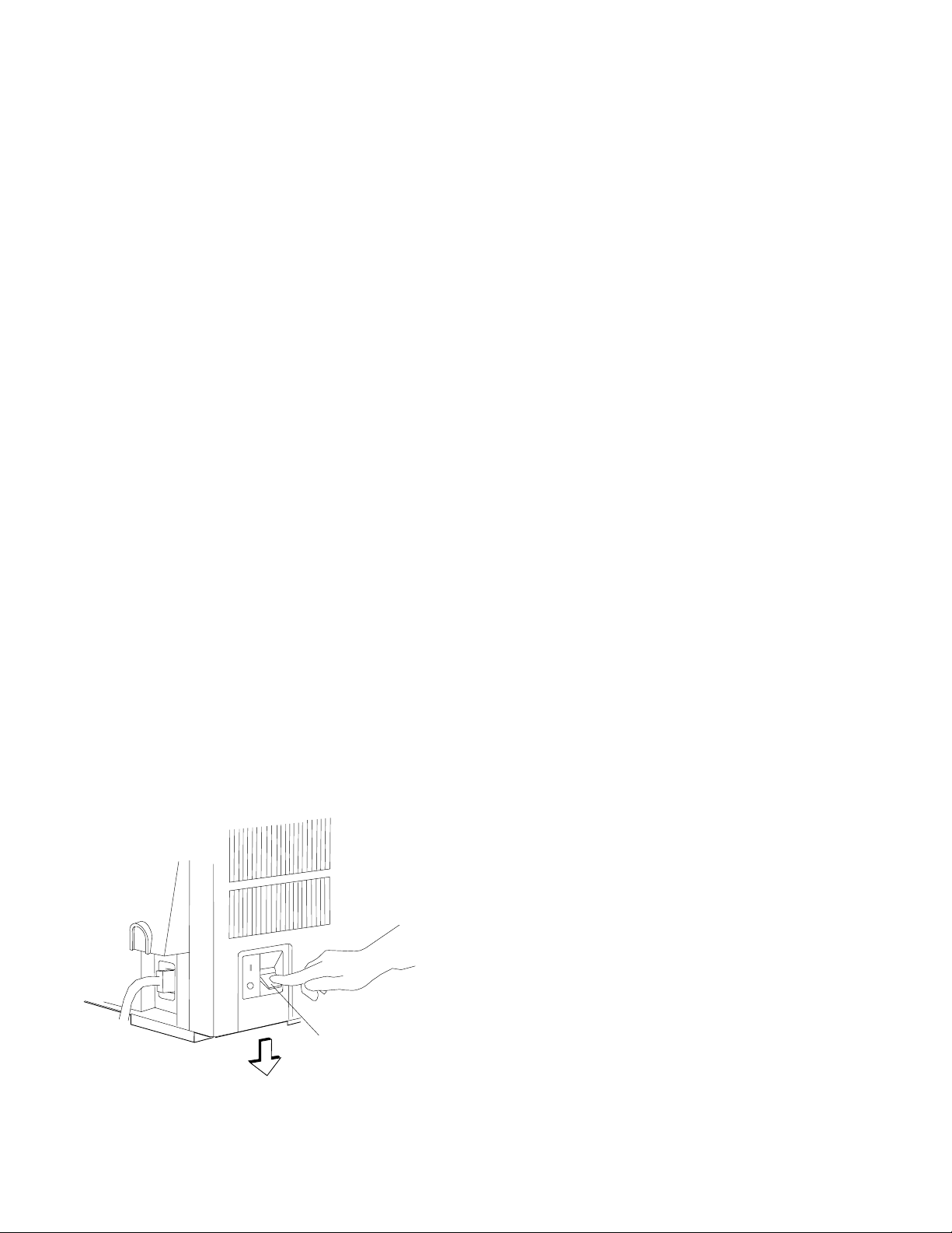
9. Compare your printout with the sample printout.
Did the lines print and is the remainder of the printout clear and
readable?
If
YES
, go to Step 10.
If NO, do the following:
a. If any of the following items are not installed correctly, the
printer can experience forms jamming, ribbon jamming, or an
incorrect printer verification printout:
Forms device
Ribbon cartridge
Forms.
Repeat the Setup Instructions on page 1-6 if you suspect a
ribbon, forms, or forms device installation problem.
b. Be sure that enough forms are loaded and press Enter or
Start to get another printout.
c. If the second printout still is not similar to the sample
printout, go to Appendix B, “Problem Solving.”
d. Once you get a good printout, go to Step 10.
10. Turn the power Off (O).
Power Switch
1-68 User’s Guide
Page 91

Setup and Checkout Complete
You have completed a simple setup and checkout of the printer.
IBM recommends that you print your power-on custom set
(Custom Set A) factory defaults and save this printout for future
reference. You are ready to attach the printer to your computer.
Go to Chapter 2, “Attaching the 4230 Printer to Your Computer”
on page 2-1.
Note: See pages 1-70 through 1-86 for making adjustments,
unloading forms, and removing the forms device.
Chapter 1. Setting Up the 4230 Printer 1-69
Page 92

Adjusting the Print Quality
After the printer prints a few lines, press Stop and verify that the
print quality is satisfactory. Good print quality includes:
Clear, legible print
Satisfactory darkness or lightness of output.
It is up to you to decide if the print quality is satisfactory.
Adjustments you can make that affect print quality include:
Tractor Tension
Incorrect tension on the right tractor can cause the paper holes
on the forms to tear, wrinkle, or jam in the printer. To adjust the
tractor tension, see “Adjusting the Tractor Tension” on
page 1-71.
Forms Thickness Setting
This setting can affect the darkness or lightness of output.
The printer will normally sense the forms thickness and adjust
itself automatically. However, if this setting is not correct, it can
be adjusted. To adjust the forms thickness, see “Adjusting the
Forms Thickness Setting” on page 1-73.
Note: The Automatic Forms Thickness Adjustment (AFTA)
mechanism automatically measures the forms thickness and
adjusts the gap from the print head to the platen rod based on
the measured value. See “Automatic Forms Thickness
Adjustment (AFTA)” on page 3-8 for information on how the
4230 Printer sets the forms thickness.
Left Margin and Top of Form Position
The adjustment of the first print position can affect the
appearance of the output, especially if you are using preprinted
forms. To adjust the position of the first print character, see
“Adjusting the Left Margin” on page 1-75. To adjust the position
of the first print line, see “Adjusting the Top of Form Position” on
page 1-77.
1-70 User’s Guide
Page 93

Tear-off Position
By moving the perforations in continuous forms close to the tear
bar, you can separate the forms more easily. To adjust the tear
position, see “Adjusting the Tear-off Position” on page 1-79.
Load Position
By using the operator panel, you can adjust the load position.
To adjust the load position, see “Adjusting the Load Position” on
page 1-81.
Print Alignment
This adjustment can affect the character formation and dot
mixing on those characters that are printed with two passes of
the print mechanism. To adjust the print alignment, see
“Adjusting the Print Alignment” on page 1-81.
Adjusting the Tractor Tension
The tractor tension adjustment controls the amount of buckle that the
forms have when they are loaded in the printer. Since the left tractor
does not move, you make this adjustment by moving the right tractor.
The ideal adjustment is to center the right and left paper holes of the
forms on the tractor pins without stretching or tearing the holes.
To adjust the tractor tension on the F2 forms device, follow these
steps:
1. Feed several forms through the printer.
2. Observe the left and right paper holes of the forms:
If the paper holes are stretched or torn on the outside edges,
the tractor tension is too tight (not enough buckle in the
forms).
If the forms twist or wrinkle as they move through the printer,
the tractor tension is too loose (too much buckle in the
forms).
Chapter 1. Setting Up the 4230 Printer 1-71
Page 94
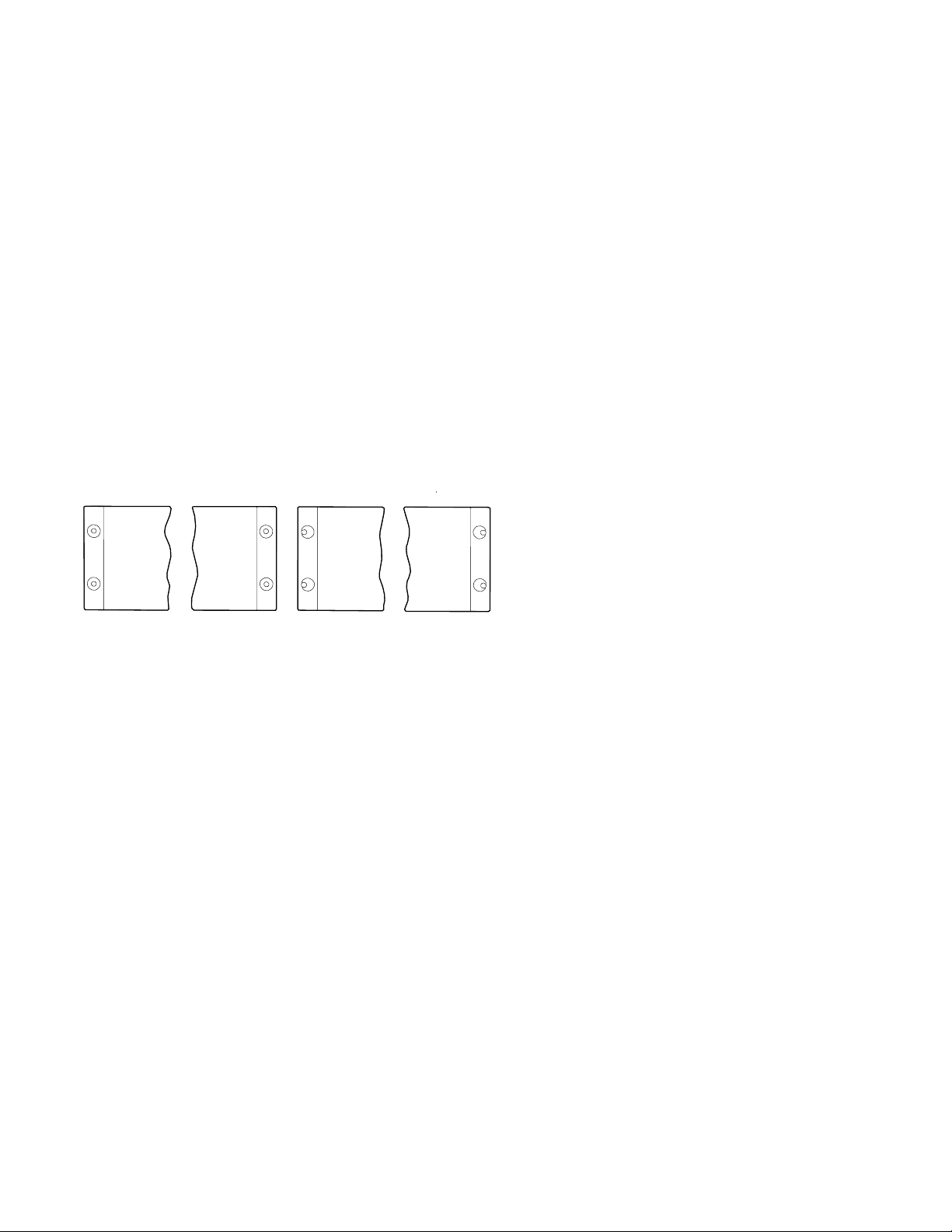
3. Adjust the right tractor as necessary:
Unlock and move the tractor toward the left side of the
printer to loosen the tension on the forms.
Unlock and move the tractor toward the right side of the
printer to tighten the tension on the forms.
Left Margin
Correct
4. Lock the tractor.
Right Margin
Left Margin
Right Margin
Incorrect
1-72 User’s Guide
Page 95

Adjusting the Forms Thickness Setting
To adjust the lightness or darkness of the print, you must increase or
decrease the gap between the print head and the platen rod. This
distance is automatically set for you by the Automatic Forms
Thickness Adjustment (AFTA), but you can make corrections to the
distance if the print output is not as you desire. It is up to you to
decide if the print is dark (or light) enough to meet your
requirements.
To adjust the forms thickness setting with the F2 forms device, follow
these steps:
1. The forms thickness setting must be adjusted when the printer is
printing or has printed and is
ready
. Press Start, if needed, to
have the printer display
READY <A>
2. To make the print darker, press Darker.
The printer displays
LIGHT |wwwwwwwwwwww-------| DARK
The print head moves closer to the paper, and the print becomes
darker.
Note: The print may not get darker if the ribbon is worn or if
there is a problem with the print head.
3. To make the print lighter, press Lighter.
The printer displays
LIGHT |wwwwwwww-----------| DARK
The print head moves farther away from the paper, and the print
becomes lighter.
Chapter 1. Setting Up the 4230 Printer 1-73
Page 96

4. When you release the key, the printer automatically saves the
current value.
Note: The J’s indicate the position of the print head relative to the
limits.
As long as you press Darker or Lighter, the printer displays an
increasing amount of darkness or lightness until one of the limits of
the gap is reached. The printer displays either
LIGHT |wwwwwwwwwwwwwwwwwww| DARK
DARKNESS LIMIT REACHED
or
LIGHT |w------------------| DARK
LIGHTNESS LIMIT REACHED
As you adjust the gap, you may also see the printer display
LIGHT |wwwwwwwwww---------| DARK
DEFAULT DARKNESS
This message tells you that the forms thickness setting is at the
automatically set value.
See “Understanding the Operator Panel” in
101, 1S2, 201, 2S2, 4S3, and 5S3 Operator Panel Instructions
IBM 4230 Printer Models
for
more information on this setting.
1-74 User’s Guide
Page 97

Adjusting the Left Margin
You can print a single line of text to help in setting the left margin
position using the Left Margin Alignment Test. You can also change
the current left margin position using this test.
You can set the left margin position from 1 to 66 units (where each
unit is 0.686 mm [0.027 in.]). The factory default setting is 10. The
| margin is measured starting at 1.27 mm (0.05 in.) from the center of
the tractor pins for continuous forms and the left edge of a cut form.
To align the left margin position, follow these steps:
1. If the printer is
ready
, press Stop.
The printer displays
NOT READY <A>
2. Enter the Operator Print Tests by pressing Test.
The printer displays
OPERATOR PRINT TESTS
Printer Demonstration
3. Press Scroll ↑ or Scroll ↓ until the printer displays
OPERATOR PRINT TESTS
Left Margin Alignment
4. Press Enter or Start to begin the test.
The printer displays
Left Margin Position
\ xxx
where
Chapter 1. Setting Up the 4230 Printer 1-75
xxx
is the current value of the left margin position.
Page 98

The printer also prints a single line of H’s.
5. If the H’s do not start where you want your left margin, press
Scroll ↑ or Scroll ↓ until the printer displays the desired value
for the left margin position.
6. Press Enter.
An asterisk (*) appears in front of the selected value. The forms
advance one line and the row of H’s prints again. This value is
now the current left margin position.
7. Repeat Steps 5 and 6 until the left margin is correctly positioned.
(You can press Line Feed or Form Feed to move the forms
between printing the rows of H’s.)
8. Press Stop or Cancel Print to exit the test.
Note: If you want the new left margin position saved when you
turn off the printer, you must save it in a Custom Set.
See “Storing Configuration Parameters” in
IBM 4230
Printer Models 101, 1S2, 201, 2S2, 4S3, and 5S3
Operator Panel Instructions
for information on saving
configurations.
You may also adjust the left margin position without
printing the row of H’s by changing the Left Margin
Position in the Configuration Menu. (See “Using Print
Format and Quality Parameters” in
IBM 4230 Printer
Models 101, 1S2, 201, 2S2, 4S3, and 5S3 Operator
Panel Instructions
.)
1-76 User’s Guide
Page 99

Adjusting the Top of Form Position
The Micro ↑ and Micro ↓ keys control fine vertical movement. Each
time you press these keys, the printer moves the form in 0.355 mm
(0.014 in.) increments.
Note: If you use the Micro ↑, Micro ↓, or Line Feed keys to adjust
the print position, you may need to reprint the page.
Open the access cover. Then open the front paper door as follows:
1. Pull the door up until it will not go any higher.
2. Push the door back slightly to lock it in the open position.
Access C over
Paper Door
Next load forms, if necessary (see “Loading Forms in the F2 Forms
Device” on page 1-60 for more information). Complete the following
steps to make fine vertical adjustments to the top of form position.
To set the top of form position, follow these steps:
1. Press Stop.
The printer displays
NOT READY <A>
Chapter 1. Setting Up the 4230 Printer 1-77
Page 100

2. If the first print line is not where you want it to be, press Micro ↑,
Micro ↓, or Line Feed until it reaches the desired line.
Note: If you need to adjust the paper downward, adjust at least
five steps beyond where you want the top of form position; then
make your final adjustment in the up direction. You can also use
the Top of Form Alignment Test (see “Top of Form Alignment” on
page 5-4) to print a line of characters to determine more
accurately where you have set the top of form position.
3. When the form is in the correct position, press Set Top of Form.
The alarm beeps and the printer displays
TOP OF FORM SET
4. Advance the form by pressing Form Feed, and decide if the form
is on the desired line. If necessary, repeat Steps 1 through 4 of
this procedure until the top of form position is correctly aligned.
5. If you plan to use the Document on Demand feature, see
“Adjusting the Tear-off Position” on page 1-79. Since you have
changed the position of the first print line, you need to adjust the
eject distance using the procedure given in that section.
1-78 User’s Guide
 Loading...