

IBEA EURO 1, 24 B, EURO 2, 25 L, 25 B Owner's Manual
...
MOD.
(24) L / B - EURO 2
MOD.
MOD.
MOD.
(25) L / B - EURO 1 / 2
(28) L / B / MUL - EURO 2
(29) L / B / MUL - EURO 1 / 2
I
GB
F
E
D
MANUALE D’ISTRUZIONE
OWNER’S MANUAL
MANUEL D’INSTRUCTION
MANUAL DE INSTRUCCIONES
GEBRAUCHSANWEISUNG
SLO
P
NL
S
PL
NAVODILO ZA UPORABO
MANUAL DE INSTRUÇÕES
INSTRUCTIEHANDLEIDING
BRUKSANVISNING
INSTRUKCJA OBSŁUGI

FIG . 8 FIG . 9 FIG . 10
FIG . 13 FIG . 14 FIG . 15
2
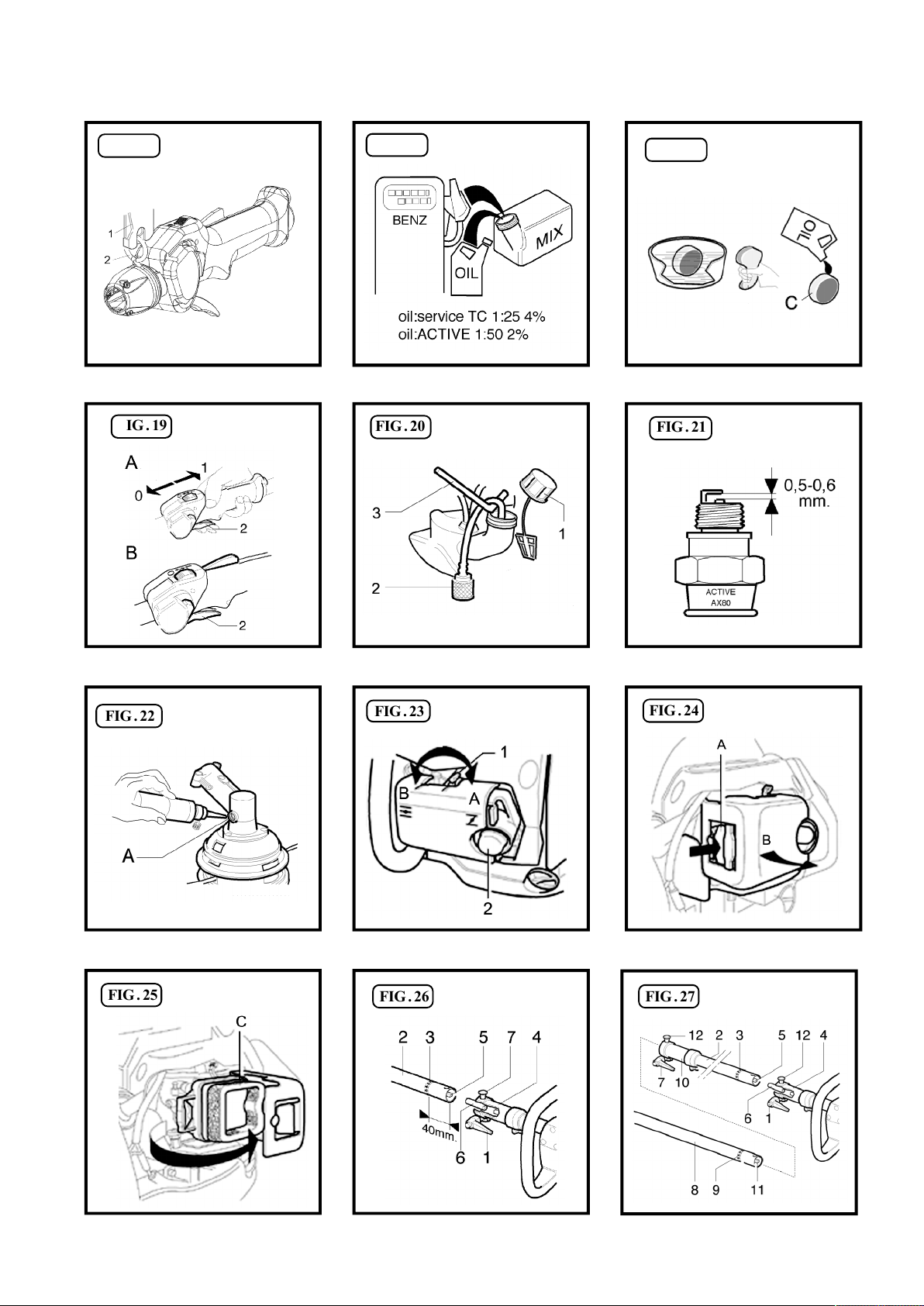
FIG . 16
FIG . 17
FIG . 18
FIG . 19
FIG . 22
FIG . 20
FIG . 23
FIG . 21
FIG . 24
FIG . 25
FIG . 26 FIG . 27
3

I
Caro cliente, la ringraziamo vivamente per aver scelto un prodotto di qualità della ditta IBEA.
Per un corretto impiego del decespugliatore e per evitare incidenti, non iniziate il lavoro senza aver letto questo manuale con
attenzione. Troverete su questo manuale le spiegazioni di funzionamento dei vari componenti e le istruzioni per i necessari
controlli e per la manutenzione.
N.B. : La casa produttrice si riserva la possibilità di apportare eventuali modifiche in qualsiasi momento e senza preavviso.
(INDICE PAG . 6)
INTRODUZIONE
GB
Dear customer, thank you very much for having chosen a quality product of the company IBEA.
For proper use of brush-saws and to avoid accidents, do not start work without having read the manual carefully. You’ll find this
guide on the explanations of operation of various components and instructions for the necessary inspections and maintenance.
N.B. : The manufacturer reserves the right to make changes at any time without notice.
(CONTENTS PAG . 13)
F
Cher client, je vous remercie beaucoup d’avoir choisi un produit de qualité de la société IBEA.
Pour un bon usage de la brosse-scies et pour éviter les accidents, il ne faut pas commencer à travailler sans avoir lu le manuel
attentivement. Vous trouverez ce guide sur les explications du fonctionnement de divers composants et des instructions pour les
inspections nécessaires et de l’entretien.
N.B. : Le fabricant se réserve le droit d’apporter des changements à tout moment sans préavis.
(INDEX PAG . 20)
E
INTRODUCTION
INTRODUCTION
INTRODUCCIÓN
Estima do cliente, muchas gra cias por haber elegido un producto de calidad de la empresa IBEA.
Para un buen uso de la brocha-y las sierras para evitar accidentes, no debemos empezar a trabajar sin haber leído el manual
cuidadosamente. Va a encontrar esta guía en las explicaciones de cómo los diversos componentes y las instrucciones para el
mantenimiento y las inspecciones necesarias.
N.B : El fabricante se reserva el derecho a realizar cambios en cualquier momento sin previo aviso.
(ÍNDICE. PAG. 27)
D
Geehrter Kunde, wir danken Ihnen, dass Sie ein Qualitätsprodukt der Firma IBEA gewählt haben.
Zur korrekten Verwendung der Heckenschere und zur Vermeidung von Unfällen muss vor dem Beginn der Arbeiten diese
Gebrauchsanweisung aufmerksam durchgelesen werden. In dieser Gebrauchsanweisung finden Sie die Erklärungen für den
Betrieb der verschiedenen Bauteile und die Anweisungen für die erforderlichen Kontrollen und Wartungsarbeiten.
N.B. : Der Hersteller behält sich das Rech vor, jederzeit und ohne Vorankündigungen irgendwelche Änderungen vorzunehmen.
(INHALTSVERZEICHNIS S. 34)
EINLEITUNG

SLO
Spoštovani kupec, zahvaljujemo se vam za nakup kakovostnega izdelka IBEA.
Za pravilno uporabo motorna kosa in za preprecevanje nesrec ne zacnite z delom ne da bi natancno prebrali ta navodila. V teh
navodilih je obrazložitev delovanja sestavnih delov in navodila za potrebne preglede in vzdrževanje.
N.B. : Podjetje si pridrži pravico glede možnih sprememb navodil kadarkoli in brez predhodnega obvestila.
(VSEBINA PAG . 41)
UVOD
P
Prezado cliente, agradecemos-lhe por ter escolhido um produto de qualidade da empresa IBEA.
Para uma utilização correcta da máquina corta-mato e para evitar acidente, não começe o trabalho se ter lido este manual com
atenção. Encontrará neste manual as explicações de funcionamento dos vários componentes e as instruções para os controlos
necessários e para a manutenção.
OBS : A casa produtora reserva-se a possibilidade de efetuar eventuais alterações em qualquer momento e sem aviso prévio.
(ÍNDICE PÁG . 47)
NL
Beste cliënt, we danken u dat u voor een IBEA kwaliteitsproduct gekozen heeft.
Vang de werkzaamheden nooit aan voordat u deze handleiding aandachtig doorgelezen heeft om een correcte gebruik van de
bosmaaier mogelijk te maken en ongevallen te vermijden. Deze handleiding bevat informatie betreffende de functionering van de
verschillende componenten en aanwijzingen voor de noodzakelijke controles en onderhoudswerkzaamheden.
N.B. : De producent behoudt zich het recht om zonder mededeling op elk gewenst moment wijzigingen door te voeren.
(INHOUDSOPGAVE PAG . 54)
S
INTRODUÇÃO
INLEIDING
INLEDNING
Bäste Kund, tack för att Du har valt en kvalitetsprodukt från företaget IBEA.
För att kunna använda busktrimmern på ett korrekt sätt och förhindra olyckor är det viktigt att den inte tas i bruk förrän du
noggrant har läst igenom denna handbok. I handboken finns förklaringar till de olika komponenternas funktioner och
instruktionerna för de nödvändiga kontrollerna och för underhållet.
OBS! Tillverkaren förbehåller sig rätten att göra ändringar på produkten utan att från gång till gång anpassa innehållet i
handboken.
(INNEHÅLLSFÖRTECKNING SIDA. 61)
PL
Drogi użytkowniku, dziękujemy bardzo za wybranie jakościowego produktu firmy IBEA.
Dla właściwego użytkowania kosy spalinowej oraz aby uniknąć wypadków, nie zaczynaj pracy bez przeczytania niniejszej
instrukcji obsługi. Znajdziesz tutaj objaśnienia wszelkich czynności oraz instruktaże związane z prawidłową obsługą,
przeglądami i użytkowaniem urządzenia.
P. S. : Producent rezerwuje sobie prawo, do zmian w każdej chwili bez uprzedzenia !
(Treść strona 68)
WPROWADZENIE
I
ITALIANO
INDICE
1. Spiegazione simboli............................................................................................................................................................................Pag. 6
2. Per la vostra sicurezza.................................................................................................................................................................................6
3. Descrizione delle parti.................................................................................................................................................................................7
4. Dati tecnici e Dichiarazione di conformità................................................................................................................................................8
5. Assemblaggio...............................................................................................................................................................................................9
6. Norme d’uso...............................................................................................................................................................................................10
7. Preparazione all’uso...................................................................................................................................................................................10
8. Manutenzione periodica............................................................................................................................................................................11
9. Rimesaggio..................................................................................................................................................................................................11
10. Certificato di garanzia..............................................................................................................................................................................12
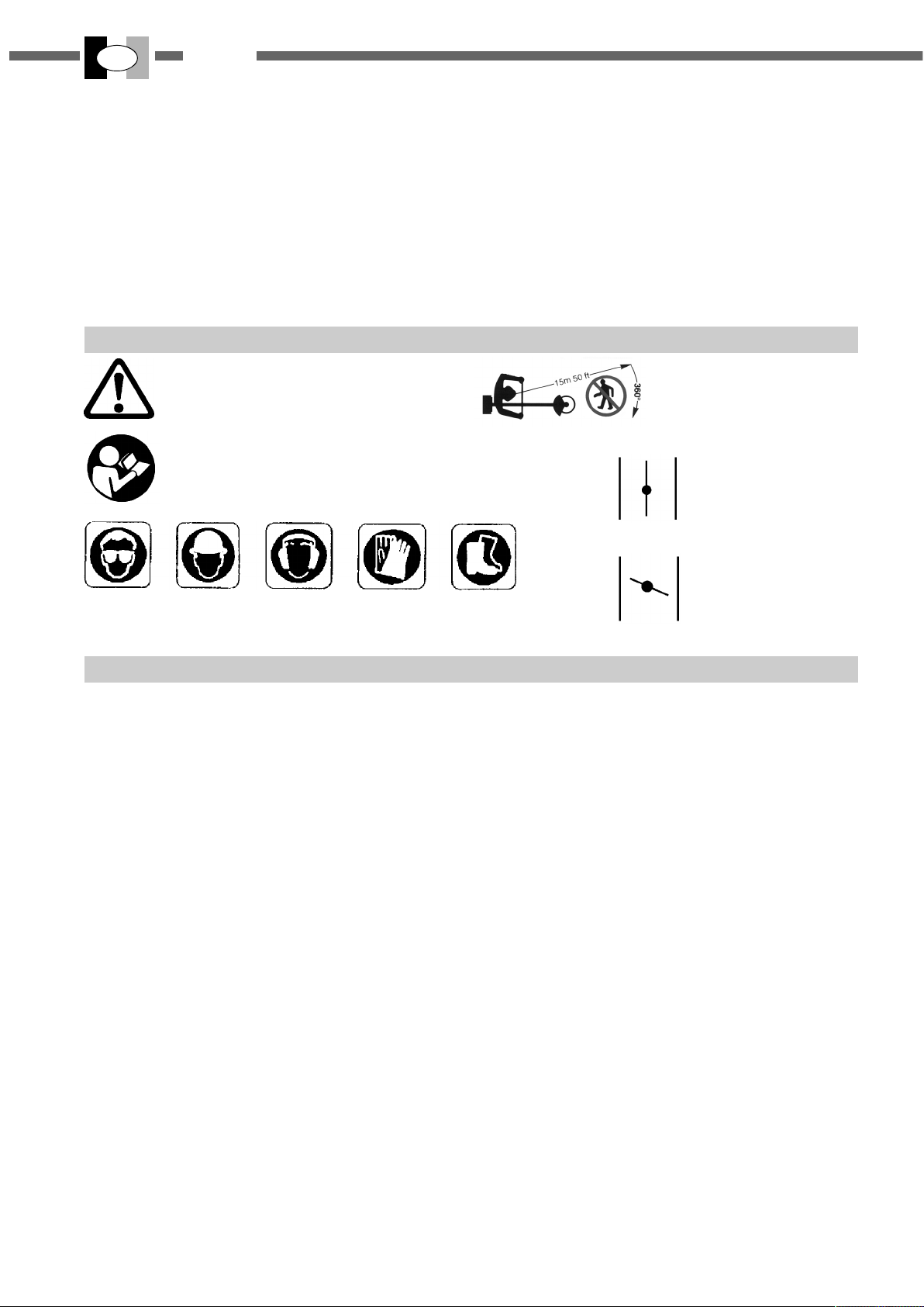
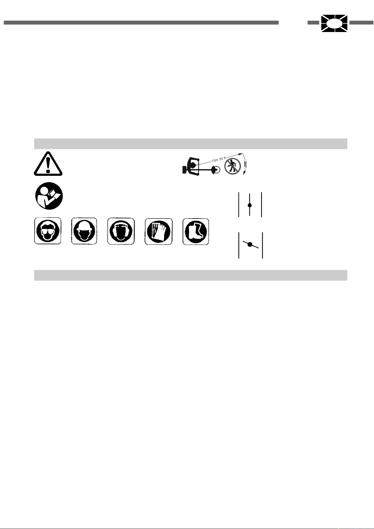
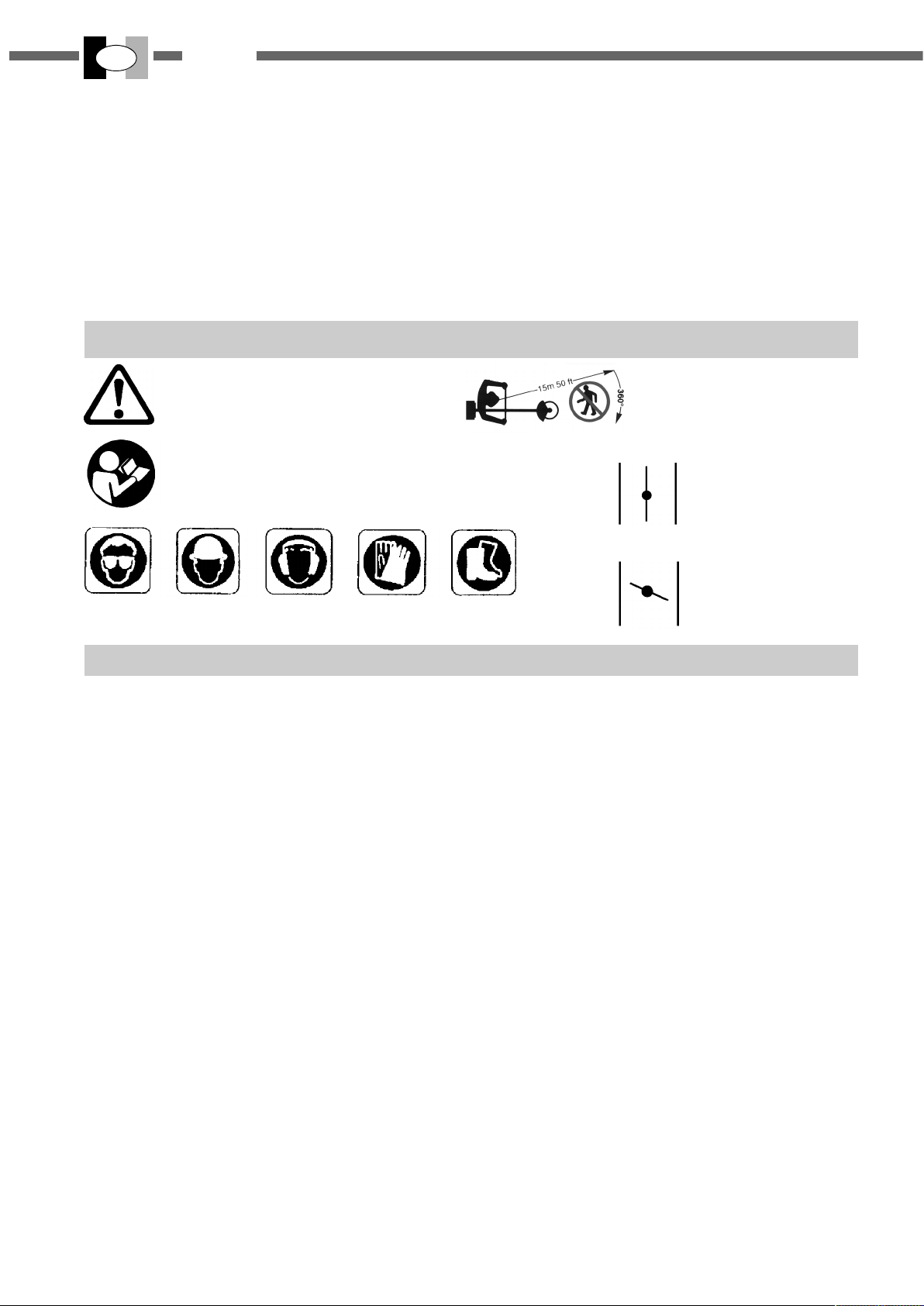
1. SPIEGAZIONE SIMBOLI
Avvertenza, pericolo ed attenzione.
Leggere il manuale di uso e manutenzione
prima di utilizzare questa macchina.
Indossare dispositivi di protezione durante il funzionamento
di questa macchina.
2. PER LA VOSTRA SICUREZZA
1-Leggere attentamente queste istruzioni ed accertarsi di
comprenderle prima di far funzionare I’unità. Attenersi a
tutte le avvertenze ed alle istruzioni di sicurezza. Conservare questo manuale a titolo di futuro riferimento.
2-Usare solamente ricambi originali, pezzi di ricambio prodotti da altri fabbricanti potrebbero adattarsi male e causare lesioni .
3-
Indossare abiti adatti ed articoli di sicurezza quali
taloni robusti, guanti, visiera o occhiali protettivi, cuffia e
casco protettivo.
4-Non indossare articoli d'abbigliamento poco aderenti o
slacciati.
5-Non permettere ad altre persone, bambini o animali di
restare nel raggio di 15 m. durante I’uso del
decespugliatore.
6-Non operare con il decespugliatore quando si è stanchi, malati o sotto I’effetto di alcool, droghe o farmaci.
7-Non permettere ai ragazzi di usare un decespugliatore.
8-Mantenersi ben saldi ed in equilibrio. Mantenere il di-
spositivo di taglio al di sotto dell’altezza della cintura.
9-Usare il decespugliatore solamente per compiti indicati
dal presente manuale.
10-Ispezionare la macchina prima di ogni impiego. Controllare che la leva acceleratore funzioni bene. Accertarsi
che il disco sia libero di girare e non sia a contatto con
corpi estranei, che non ci siano perdite di carburante, che
i dispositivi di sicurezza non siano allentati ecc..Sostituire
le parti danneggiate.
11-Avviare il decespugliatore solo in luoghi ben ventilati, i
gas di scarico, se respirati, possono causare una asfissia mortale.
12-Accertarsi che la protezione del disco o della testina e
gli altri dispositivi siano montati correttamente e saldamente.
: stivali, pan-
6
Tenere le persone lontane
15 mt.
Farfalla aria aperta,
funzionamento
Farfalla aria chiusa,
13-Trasportare il decespugliatore a motore fermo e con il
copri disco montato.
14-Usare esclusivamente il filo di nylon o il disco raccomandato dal fabbricante, per esempio non usare in alcun
modo fili di metallo o corde rinforzate in metallo, visto che
potrebbero rompersi e formare proiettili pericolosi.
15-Con il motore in moto non fare alcuna manutenzione e
non toccare il disco.
16-Una volta spento il motore, prima di appoggiare per
terra l‘unità accertarsi che il dispositivo di taglio si sia
arrestato.
17-Arrestare il motore e lasciarlo raffreddare prima del rifornimento. Riempire il serbatoio lontano da fonti di calore
e non fumare durante il rifornimento o la miscelazione del
carburante.
18-Non togliere il tappo del serbatoio con il motore in moto.
19-Asciugare il carburante eventualmente rovesciato sul-
la macchina. Spostare il decespugliatore di 3 metri dal
punto
di rifornimento prima di mettere in moto il motore.
20-Non usare carburante per operazioni di pulizia.
21-Non controllare la scintilla della candela vicino al foro
della candela.
22-Non lavorare con una marmitta danneggiata.
23-Prima dell ‘uso del decespugliatore, liberare I’area da
tosare da tutti gli oggetti: quali sassi, pezzi di vetro, filo
24-Prima di riporre in magazzino il decespugliatore, la-
sciare raffreddare il motore e svuotare il serbatoio di carburante.
25-Riporre il decespugliatore in modo da prevenire le lesioni accidentali causate da oggetti taglienti, lontano da
fonti di calore e sollevato dal suolo.
26-Non avviare il motore senza il braccio (trasmissione)
montato.
ITALIANO
I
27-Assicurarsi che il dispositivo di taglio sia stato installato correttamente e che sia ben stretto.
28-Sostituire la testina o il disco se apparissero incrinati,
scheggiati o danneggiati in qualsiasi modo.
29-Indossare i guanti per maneggiare o effettuare la manutenzione della lama.
30-Con il motore al minimo il disco non deve girare. In
caso contrario regolare la vite del minimo.
31-Trasportare il decespugliatore a motore fermo e con il
copri disco montato.
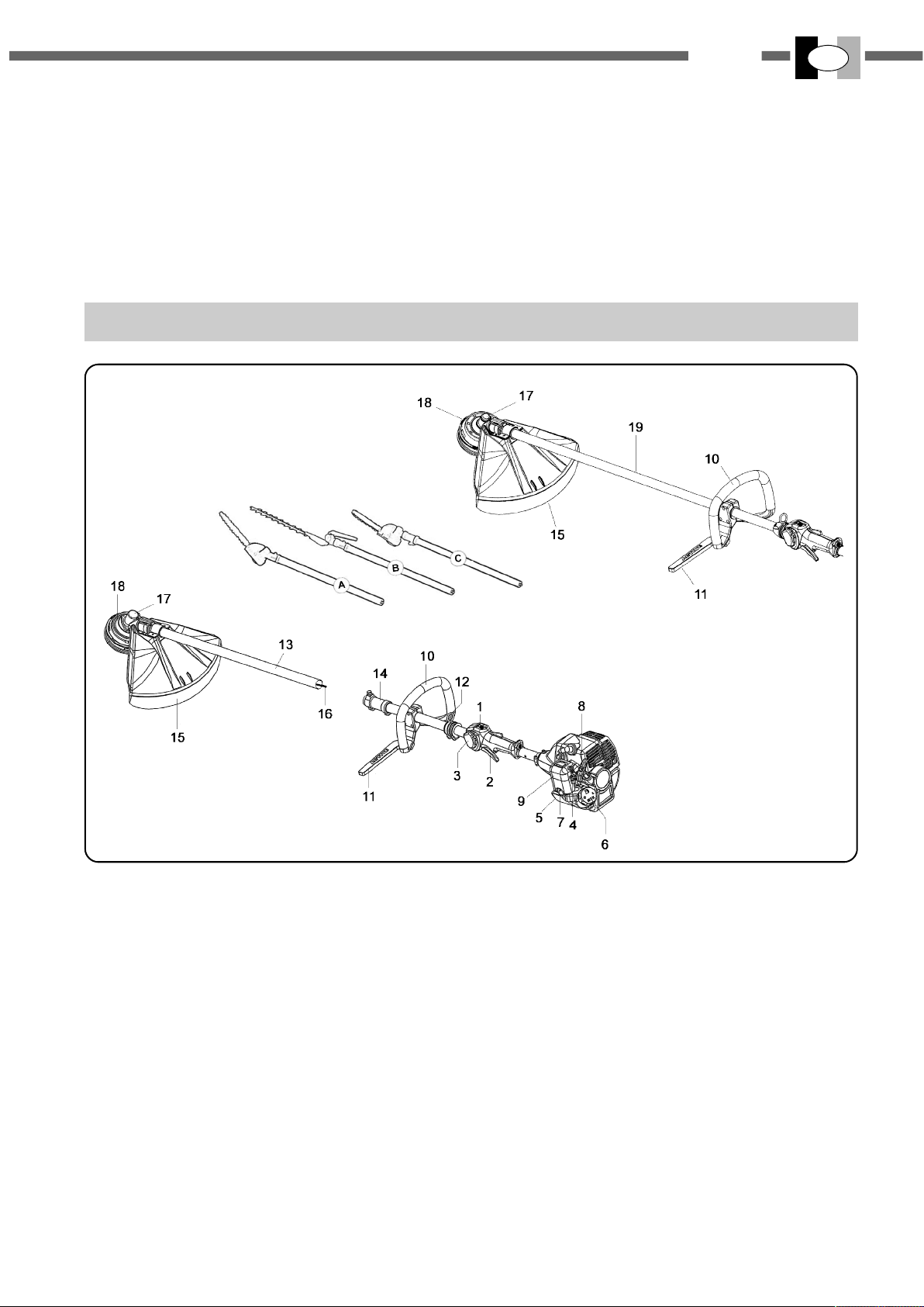
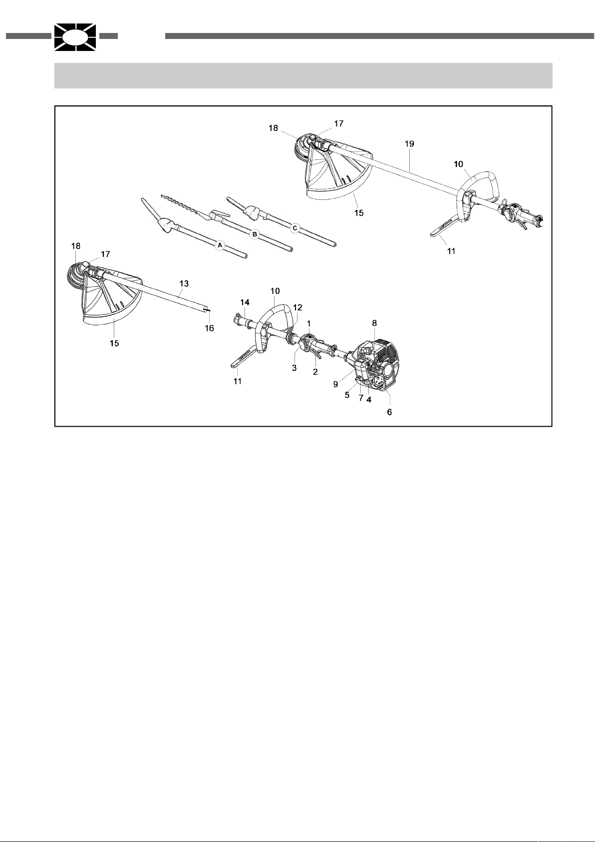
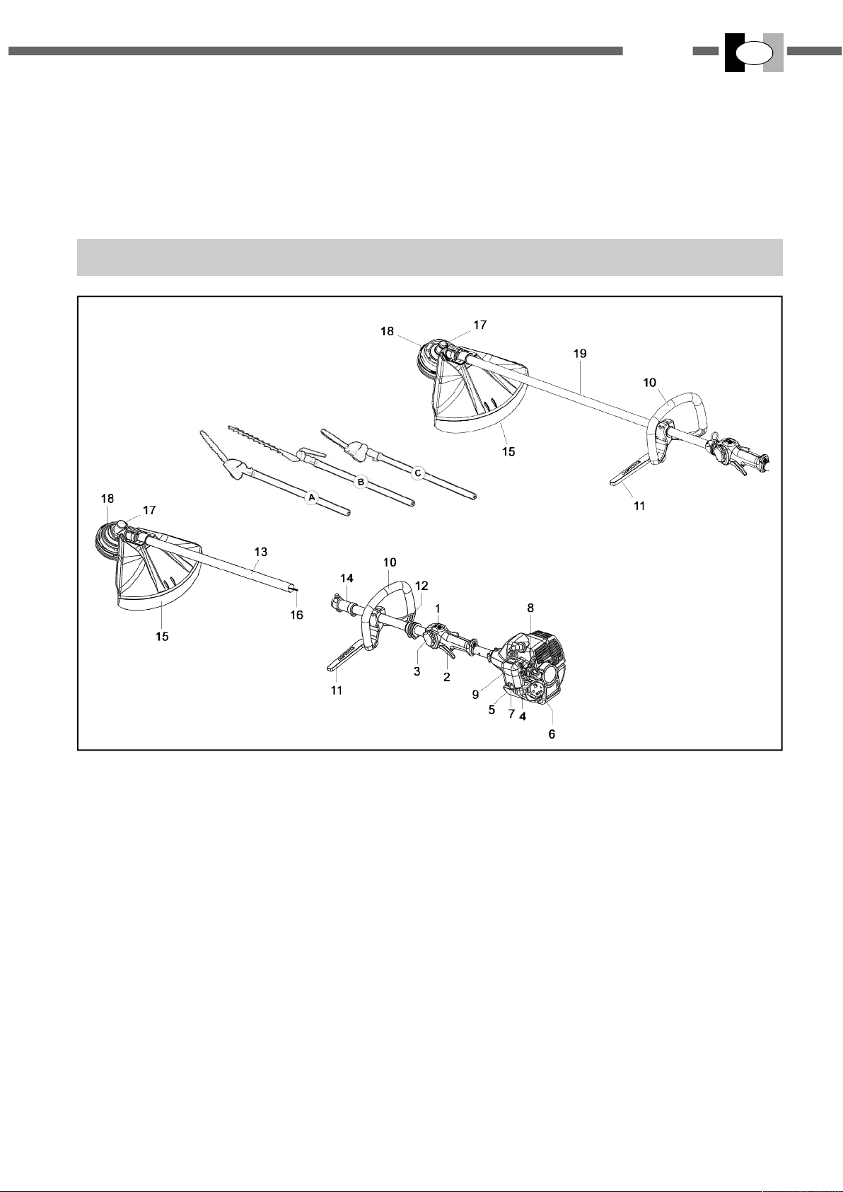
3. DESCRIZIONE DELLE PARTI
33-Usare sempre le lame affilate,una lama senza filo ha
mag- gior probabilità di bloccarsi e causare contraccolpi.
Sostituire i dischi che abbiano perso il filo. NON CERCARE di affilarli.
34-E’ necessario arrestare il motore ed esaminare il disco
tutte le volte che si colpisce un oggetto duro.
35-Gli attrezzi da taglio oppure gli accessori usati dovranno essere originali IBEA oppure essere espressamente
approvati per I' applicazione al presente modello.
36-Quando viene applicato il disco per il taglio del legno,
montare la protezione disco specifica .
1. Interruttore di arresto (STOP)
2. Leva acceleratore
3. Semi acceleratore
4. Levetta farfalla aria (STARTER)
5. Serbatoio carburante
6. Tappo serbatoio carburante
7. Primer (spurgo del carburatore)
8. Impugnatura avviamento motore
9. Filtro aria
10. Impugnatura anteriore
11. Barra di protezione per l’utilizzatore
12. Attacco cinghiaggio
15. Protezione di sicurezza
17. Coppia conica
18. Testina a filo di nylon
19. Tubo di trasmissione
Solo per modelli MULTIFUNCTION:
13. Tubo di trasmissione
14. Giunto accoppiamento accessori
16. Albero di trasmissione
ACCESSORI A RICHIESTA:
A. Potatore angolato 35°
B. Tagliasiepi
C. Potatore dritto
7

I
ITALIANO
4. DATI TECNICI E DICHIARAZIONE DI CONFORMITA’
ACTIVE s.r.l. Zona Artigianale - 26037 S. Giovanni in Croce (CR)
dichiara sotto la propria responsabilità che le macchine:
MODELLO IBEA
CILINDRATA cm³
POTENZA Kw /CV
CARBURATORE
ACCENSIONE
CAPACITA' SERB. CARB.
FRIZIONE
SISTEMA ANTIVIBRAZIONE
MANUBRIO / IMPUGNATURA
ACCELERATORE
TUBO TRASMISSIONE
PESO Kg.
MODELLO
FINO AL NUMERO DI SERIE
DAL NUMERO DI SERIE
(24 - 25) L
24.5
1.03 / 1.4
IMPUGNATURA IMPUGNATURA
DISPOSITIVO DI SICUREZZA CON SGANCIO AUTOMATICO
Ø 24 Ø 26
4.8 kg 5.3 kg
sono conformi ai requisiti stabiliti dalle direttive:
EURO 1
(25) L / B (25) L / B
(24) L / B
25XX9999
Ø 26 Ø 24
E25XX0001 / E24XX0001
(24 - 25) B
A MEMBRANA WALBRO PRIMER TYPE
ELETTRONICA
Diametro 54 mm
tra motore e trasmissione
MANUBRIO
Ø 24
5.3 kg 5.3 kg
EURO 2
(28 - 29) L
0.5 L
4.8 kg
EURO 1
(29) L / MUL / B (29) L / MUL / B
(28) L / MUL / B
29XX9999
(28 - 29) MUL
(28 - 29) B
28.5
1.25 / 1.7
MANUBRIO
Ø 24
5.3 kg
EURO 2
E28XX0001 / E29XX0001
DIRETTIVE
MODELLO ATTREZZO
(24 - 25) L
(28 - 29) L-MUL
(24 - 25) B
(28 - 29) B
La documentazione tecnica è depositata in Direzione Tecnica.
2006/42/CE - 2004/108/CE - 2000/14/CE - 2002/44/CE (Allegato V)
LIVELLO PRESSIONE
ACUSTICA
(EN ISO 22868)
90 dB (A)
99 dB (A)
90 dB (A)
99 dB (A)
2012/46/CE (Allegato VI)
LIVELLO POTENZA
ACUSTICA
(EN ISO 22868)
103 dB (A)
110 dB (A)
103 dB (A)
110 dB (A)
26037 San Giovanni in Croce (CR) - ITALY
LIVELLO VIBRAZIONI (m/s²)
(UNI EN ISO 22867)
Impugnatura
DX SX
5
5,1
4,3
4,5
ALBERTO GRIFFINI
PRESIDENTE
ACTIVE S.r.l.
Via Delmoncello, 12
01/03/2017
4,7
4,9
4,1
4,3
8
5. ASSEMBLAGGIO
ITALIANO
I
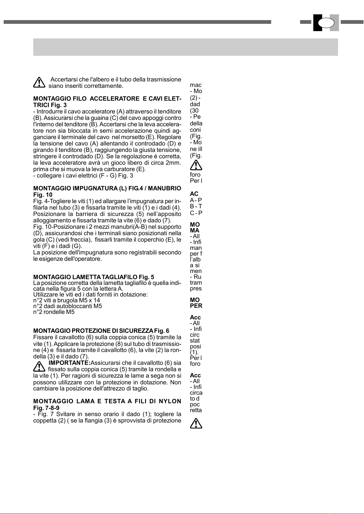
MONTAGGIO MOTORE TRASMISSIONE
- Assemblare il motore (1) alla trasmissione (2) e fissarlo
tramite le viti (3) (vedi fugura 2).
Accertarsi che l'albero e il tubo della trasmissione
siano inseriti correttamente.
MONTAGGIO FILO ACCELERATORE E CAVI ELET-
TRICI Fig. 3
- Introdurre il cavo acceleratore (A) attraverso il tenditore
(B). Assicurarsi che la guaina (C) del cavo appoggi contro
l'interno del tenditore (B). Accertarsi che la leva accelera-
tore non sia bloccata in semi accelerazione quindi ag-
ganciare il terminale del cavo nel morsetto (E). Regolare
la tensione del cavo (A) allentando il controdado (D) e
girando il tenditore (B), raggiungendo la giusta tensione,
stringere il controdado (D). Se la regolazione é corretta,
la leva acceleratore avrà un gioco libero di circa 2mm.
prima che si muova la leva carburatore (E).
- collegare i cavi elettrici (F - G) Fig. 3
MONTAGGIO IMPUGNATURA (L) FIG.4 / MANUBRIO
Fig. 10
Fig. 4-Togliere le viti (1) ed allargare l’impugnatura per in-
filarla nel tubo (3) e fissarla tramite le viti (1) e i dadi (4).
Posizionare la barriera di sicurezza (5) nell’apposito
alloggiamento e fissarla tramite la vite (6) e dado (7).
Fig. 10-Posizionare i 2 mezzi manubri(A-B) nel supporto
(D), assicurandosi che i terminali siano posizionati nella
gola (C) (vedi freccia), fissarli tramite il coperchio (E), le
viti (F) e i dadi (G).
La posizione dell'impugnatura sono registrabili secondo
le esigenze dell'operatore.
MONTAGGIO LAMETTA TAGLIAFILO Fig. 5
La posizione corretta della lametta tagliafilo è quella indi-
cata nella figura 5 con la lettera A.
Utilizzare le viti ed i dati forniti in dotazione:
n°2 viti a brugola M5 x 14
n°2 dadi autobloccanti M5
n°2 rondelle M5
MONTAGGIO PROTEZIONE DI SICUREZZA Fig. 6
Fissare il cavallotto (6) sulla coppia conica (5) tramite la
vite (1). Applicare la protezione (8) sul tubo di trasmissio-
ne (4) e fissarla tramite il cavallotto (6), la vite (2) la ron-
della (3) e il dado (7).
IMPORTANTE:Assicurarsi che il cavallotto (6) sia
fissato sulla coppia conica (5) tramite la rondella e
la vite (1). Per ragioni di sicurezza le lame a sega non si
possono utilizzare con la protezione in dotazione. Non
cambiare la posizione dell'attrezzo di taglio.
MONTAGGIO LAMA E TESTA A FILI Dl NYLON
Fig. 7-8-9
- Fig. 7 Svitare in senso orario il dado (1); togliere la
coppetta (2) ( se la flangia (3) è sprovvista di protezione
per il dado ), e la flangia (3).
Montare la lama (4) seguendo la disposizione illustrata in
(Fig. 8).
- Assicurarsi che la flangia superiore (5) sia posizionata
correttamente. Montare la lama assicurarsi che sia centrata sulla flangia (5). Assicurarsi del giusto senso di rotazione (scritte o freccia di direzione rivolte verso l'alto con
macchina in posizione di lavoro).
- Montare la flangia inferiore (3), coppetta di protezione
(2) - (se la flangia inferiore è sprovvista di protezione per il
dado), avvitare il dado (1) in senso antiorario a Kgm 3.0
(30 Nm).
- Per bloccare il dado (1), girare la lama sino a che il foro
della flangia superiore corrisponda con il foro della coppia
conica, ed inserire la chiave a brugola in dotazione (4mm),
(Fig. 8)
- Montare la testina a fili di nylon seguendo la disposizione illustrata: Flangia superiore, testina a fili di nylon.
(Fig. 9)
Serrate a mano in senso antiorario
dopo aver inserito la chiave a brugola (4 mm) nel
foro 3 della coppia conica.
Per la vostra sicurezza utilizzare lame originali
ACCESORI A RICHIESTA (Mod. MUL).
A - POTATORE ANGOLATO 35°
B - TAGLIASIEPI
C - POTATORE DRITTO
MONTAGGIO DEGLI ACCESSORIO (A- B - C) SULLA
MACCHINA Fig.26
- Allentare, in senso antiorario, la leva (1)
- Infilare il tubo (2), fino al riferimento (3) circa 40mm, nel
manicotto (4) tenendo il piolino (7) spostato verso l'alto,
per facilitare l’inserimento dell’albero (5) nel mozzo dell’albero (6), ruotare l’attrezzo un poco a destra e un poco
a sinistra fino a che l’attrezzo/tubo sia inserito correttamente.
- Ruotare l’attrezzo nella posizione di lavoro e bloccarlo
tramite la leva (1). Per la sicurezza dell'operatore il tubo 2
presenta un foro dove deve inserirsi il piolino 7.
MONTAGGIO DELLA PROLUNGA (a richiesta e SOLO
PER GLI ATTREZZI A - B - C)
Accopiamento prolunga - macchina fig.27:
- Allentare, in senso antiorario, la leva (1).
- Infilare il tubo (2) della prolunga fino al riferimento (3),
circa 40mm., nel manicotto (4) tenendo il piolino 12 spostato verso l'alto. Ruotare il manicotto (10) nella stessa
posizione che il manicotto (4) e bloccarlo tramite la leva
(1).
Per la sicurezza dell'operatore il tubo 2 e 8 presentano un
foro dove deve inserirsi il piolino 12.
Accopiamento accessorio - prolunga fig.27:
- Allentare, in senso antiorario, la leva (7)
- Infilare il tubo (8) dell’accessorio fino al riferimento (9),
circa 40mm., nel manicotto (10). Per facilitare l’inserimento dell’albero (11) ruotare l’attrezzo un poco a destra e un
poco a sinistra fino a che l’attrezzo/tubo sia inserito correttamente.
ATTENZIONE: per l’utilizzo degli accessori
A - B - C vedi il manuale d’istruzione specifico
allegato ad ogni accessorio.
L’estensione della macchina (solo con gli accessori
A - B e D) non può superare i 1500mm., altrimenti è
pericoloso. Si può utilizzare una sola prolunga, la
750mm o la 1500mm.
9

I
ITALIANO
6. NORME D'USO
ATTENZIONE: Prima di usare il decespugliatore leggere
attentamente le norme di sicurezza.
Si raccomanda di usare il decespugliatore dalla parte destra del corpo (Fig.26), si dà così la possibilità ai gas di
scarico di uscire liberamente senza venir ostruiti dagli abiti
dell’operatore. Se siete nuovi all’uso del decespugliatore
seguite il primo periodo di addestramento. Ispezionare
sempre attentamente la macchina prima dell’uso. Verificare che non vi siano viti allentate, parti danneggiate e
perdite di carburante. Controllate periodicamente le condizioni del sistema antivibrante. Evitate un uso del
decespugliatore eccessivamente prolungato, le vibrazioni possono essere dannose. Prima di ogni utiliz-
zo rimuovete dall‘area interessata: pietre, vetri, funi, parti
metalliche e tutti i corpi estranei che potrebbero aggrovigliarsi sulle parti rotanti o essere proiettati pericolosamente
a distanza. Indossare il cinghiaggio e agganciare il
decespugliatore. Tenere sempre entrambe le mani sulle
impugnature durante il funzionamento del decespugliatore
Fig. 26. Utilizzare il decespugliatore come illustrato nella
Fig. 16. Per facilitare l‘operazione di taglio e per ragioni di
sicurezza, posizionare sempre il fermo della protezione
contro il materiale da tagliare. Verificare sempre che il
disco non subisca incrinature dopo urti accidentali contro
oggetti estranei. Sostituire gli accessori ( dischi, testine
a filo , protezioni, cinghiaggi) eventualmente danneggiati
o eccessivamente usurati.
Fig. 15 Testina a fili di NYLON ACTIVE®. Il dispositivo
consente il caricamento del filo senza smontare la testina
(è un brevetto ACTIVE).
- Usare sempre lo stesso diametro del filo originale per
non sovraccaricare il motore.
- Spegnere il motore. Indossare i guanti di lavoro.
Ruotare, in senso orario, il pomolo (1) fino a che la freccia (2) del pomolo sia allineata con una delle boccole
(6).
- Inserire il tubo (4) in dotazione attraverso la testina.
- Infilare il filo e togliere il tubo.
Congiungere le estremità del filo e tirare il filo in modo di
avere i due rami del filo della stessa lunghezza.
- Ruotare il pomolo in senso orario, avendo cura di ten-
dere i due rami del filo ogni 3 giri, fino al completo
avvolgimento.
SMONTAGGIO DELLA TESTINA
Premere il pomolo (1). Contemporaneamente premere
la linguetta (5) ed estrarre parzialmente il coperchio (7) dal
corpo della testina .Mantenendo il pomolo premuto,
premere l’altra linguetta ed estrarre il coperchio.
ASSEMBLAGGIO DELLA TESTINA
Montare le boccole (6) nella loro sede del coperchio (7).
Montare il rocchetto nel coperchio (7). Posizionare la
molla sul rocchetto oppure all’interno del corpo della
testina.
Montare il coperchio/rocchetto/boccole nel corpo della
testina assicurandosi che le linguette (5) siano nella loro
sede.
FUNZIONAMENTO
Per allungare il filo: far girare la testina mantenendo il motore
accelerato.Battere al suolo il pomolo (1). Ogni scatto
corrisponde a circa 3 cm. di fuoriuscita del filo.
Nota: non battere la testina su superfici dure può essere
pericoloso.
7. PREPARAZIONE ALL'USO
OPERAZIONI PRELIMINARI
Regolazione del cinghiaggio e della posizione del
decespugliatore. Indossare il cinghiaggio agganciare il
decespugliatore al cinghiaggio tramite il gancio. Posizionare la fibbia per ottenere la corretta altezza del
decespugliatore.
CARBURANTE
ATTENZIONE il decespugliatore è equipaggiato da un mo-
tore 2 tempi, quindi si deve utilizzare esclusivamente carburante miscelato con olio.
Preparare solo la miscela necessaria all’uso. Non fumare
ed eseguire il rifornimento carburante sempre a motore
spento e lontano da fiamme. Usare carburante con numero di ottani non inferiore a 90. Miscelate la benzina
con olio ACTIVE con il rapporto 50:1 (2%). Se non
avete l’olio ACTIVE usare eclusivamente olio per motori 2 tempi nella proporzione di 25 : 1 (4%). Fig. 17
Importante: Mescolate fortemente e a lungo la tanica,
questa operazione deve essere accuratamente ripetuta
ogni volta che si preleva carburante dalla tanica. Le caratteristiche della miscela sono soggette ad invecchiamento e quindi si alterano nel tempo. Non usate miscela preparata da più settimane, si potrebbero verificare danni al
motore. Riempire il serbatoio miscela solo per 3/4 per
permettere I’espansione della stessa.
lasciare fuoriuscire I’eventuale eccesso di pressione.
Dopo il rifornimento serrare correttamente il tappo del serbatoio. Spostare il decespugliatore di almeno 3 m. dal
punto di rifornimento prima di mettere in moto il motore.
Prima del rifornimento pulire accuratamente intorno al tappo del serbatoio. La sporcizia all’interno del serbatoio
causa problemi di funzionamento al motore. Assicurarsi
che la miscela sia omogenea agitando la tanica o il serbatoio.
AVVIAMENTO Fig. 19 - 23
Appoggiare il decespugliatore su di una superficie piana
e sgombra e verificare che I’attrezzo di taglio sia libe-
ro di girare.
Portare I’interruttore sulla posizione (1) fig. 19.
Premere il bulbo (2) 5 o 6 volte fig. 23.
Portare la leva dello starter (1) in posizione chiusa (A)
fig. 23.
Tenendo fermo il decespugliatore tirare l’avviamento ed ai
primi scoppi del motore riportare la leva starter nella posizione originale aperta (B).
Ripetere la manovra d'avviamento finchè il motore non parte. A motore avviato, premere I’acceleratore (2) per sbloccarlo dalla posizione di semiaccelerazione e portare il motore al minimo fig. 19.
RIFORNIMENTO
ATTENZIONE ll rifornimento deve essere effettuato a mo-
tore spento. Svitare lentamente il tappo del serbatoio per
10

ATTENZIONE: quando il motore è già caldo, non premere
il bulbo (2) , non usare lo starter per I’avviamento. Non
rilasciare la corda d’avviamento, ciò potrebbe danneggiare il gruppo avviamento.
ARRESTO MOTORE
Portare la leva acceleratore (2) Fig.19 al minimo ed attendere alcuni secondi per permettere il raffreddamento del
motore.Portare l'interruttore di massa nella posizione di
stop (0) fig. 19.
ATTENZIONE: con motore al minimo 2600 ~ 3000
giri l'attrezzo di taglio non deve girare. Se il minimo e troppo elevato svitare in senso antiorario la vite (H)
Fig. 3
8. MANUTENZIONE PERIODICA
Controllare per iodicamente che tutte le viti del
decespugliatore siano nelle loro sedi e ben serrate. Sostituire le lame danneggiate, usurate, criccate e non piane. Verificare sempre il corretto montaggio della testina a
fili di nylon o la lama e che la vite che blocca la lama sia
ben serrata.
FILTRO ARIA Fig. 18 - 24 - 25
- Verificare periodicamente il filtro d'aria in funzione delle
condizioni di lavoro
- Togliere il coperchio (B)
- Togliere il filtro (C)
- Pulire il filtro (C) con miscela di benzina / olio e strizzatelo
- Mettere tassativamente l’olio sul filtro (C)
- Controllare le parti e se necessario sostituirle. Montare
in senso inverso allo smontaggio.
ATTENZIONE : Per migliori risultati e una lunga durata, si raccomanda di utilizzare olio per filtri ACTIVE.
FILTRO CARBURANTE Fig. 20
Per la pulizia o per la sostituzione, togliere il tappo dal
serbatoio ed estrarre il filtro (2) servendosi di un gancio (3)
o di una pinza a becchi lunghi.
Verificare periodicamente le condizioni del filtro; in caso
di sporcizia eccessiva, provvedere alla sua sostituzione.
ITALIANO
I
ATTENZIONE
Dopo un uso intenso della macchina non spegnare
improvvisamente il motore ma lasciarlo girare al
minimo per qualche minuto per stabilizzarlo.
Le marmitte dotate di catalizzatore diventano molto calde durante l’uso e rimangono così per molto
tempo dopo l’arresto del motore. Questo avviene
anche quando il motore è al minimo. Il contatto può
causare bruciature della pelle.
Non aggiungere mai carburante a una macchina con
il motore in funzione o caldo.
PERICOLO D’INCENDIO.
Spostarsi almeno 3 metri dalla posizione in cui è
stato effettuato il rifornimento prima di avviare il
motore. Non fumare!!
MOTORE
Regolarmente, onde evitare surriscaldamenti al motore,
rimuovere polvere e sporco dalle feritoie, dal coperchio
cilindro e dalle alette del cilindro utilizzando pennello o
aria compressa.
CANDELA Fig. 21
Periodicamente (almeno ogni 50 ore) smontate e pulite la
candela e regolate la distanza tra gli elettrodi (0.5 - 0.6).
Sostituitela se eccessivamente incrostata o usurata e
comunque entro 100 ore di lavoro. In caso di eccessive
incrostazioni controllate la regolazione del carburatore, la
percentuale 4% (1:25) dell'olio miscela ed accertarsi che
l'olio sia di ottima qualità e del tipo per motori 2 tempi.
COPPIA CONICA Fig. 22
Ogni 50 ore di funzionamento aggiungete nella scatola
ingranaggi del grasso per ingranaggi ad alta velocità, attraverso il foro (A).
Raccomandato il grasso ACTIVE Ref. 21230
DISCO
Verificare sempre le condizioni generali della lama.
Sostituire la lama appena appaiono crepe o rotture.
9. RIMESSAGGIO
Seguire tutte le norme di manutenzione precedentemente descritte.
Pulire perfettamente il decespugliatore e ingrassare le
parti metalliche.
Svuotare il serbatoio carburante e fate funzionare il
motore sino ad esaurimento del carburante residuo.
Conservate il decespugliatore in ambiente asciutto.
Togliere la candela, versare un pò d'olio nel cilindro,
ruotare l'albero motore alcune volte tramite l'avviamento
per distribuire l'olio, rimontare la candela.
ATTENZIONE: tutte le operazioni di manutenzione non
riportate sul presente manuale devono essere effettuate
da una officina autorizzata.
11
I
ITALIANO
10. CERTIFICATO DI GARANZIA
Questa macchina è stata concepita e realizzata attraverso le più moderne tecniche produttive; la Ditta
costruttrice garantisce i propri prodotti per un periodo di 24 mesi dalla data di acquisto ad eccezione dei
prodotti per servizio professionale continuo, adibiti a lavori per conto terzi, per i quali la garanzia è di 12
mesi dalla data di acquisto.
CONDIZIONI DI GARANZIA
1) La garanzia viene riconosciuta a partire dalla data di acquisto. La Ditta costruttrice sostituisce gratuita-
mente le parti difettose nel materiale, nelle lavorazioni, nella produzione. La garanzia non contempla la
sostituzione della macchina.
2) Il personale tecnico interverrà nei limiti di tempo concessi da esigenze organizzative e in ogni caso il più
presto possibile, e l'eventuale ritardo non potrà determinare richieste di risarcimento dei danni nè prolungamento del periodo di garanzia.
3) Per richiedere l'assistenza in garanzia è necessario esibire al personale autorizzato il certificato di
garanzia timbrato dal rivenditore, compilato in tutte le sue parti e corredato di fattura d'acquisto o scontrino
fiscale o altro documento reso fiscalmente obbligatorio comprovante la data di acquisto.
4) La garanzia decade in caso di:
- Assenza palese di manutenzione
- Utilizzo non corretto del prodotto o manomissione
- Utilizzo dei lubrificanti o combustibili non adatti
- Utilizzo di parti di ricambio o accessori non originali.
- Interventi effettuati da personale non autorizzato
5) La Ditta costruttrice esclude dalla garanzia le parti soggette ad un normale logorio di funzionamento:
attrezzi di taglio, guarnizioni, candela, corda avviamento, dispositivi di sicurezza a taglio o a frizione, filtri
ecc.
6) Eventuali danni causati durante il trasporto, devono essere immediatamente segnalati al trasportatore
pena il decadere della garanzia.
7) Se guasti o rotture dovessero accadere nel periodo di garanzia o dopo di esso il cliente non ha diritto di
sospendere il pagamento nè ad alcuno sconto sul prezzo.
8) La ditta costruttrice non risponde di eventuali danni diretti od indiretti, causati a persone o cose da guasti
della macchina o conseguenti alla forzata sospensione prolungata nell'uso della stessa.
MOD.
S.N. n.°
DATA:
...........................
24 L
25 L
RIVENDITORE:
ACQUISTATO DAL SIG.
24 B
25 B
28 L
29 L
28 MUL
29 MUL
28 B
29 B
12
ENGLISH
GB
CONTENTS
1. Symbol interpretation........................................................................................................................................................................Pag.13
2. For your safety...........................................................................................................................................................................................13
3. Description.................................................................................................................................................................................................14
4. Specifications and Declaration of conformity.......................................................................................................................................15
5. Assembly....................................................................................................................................................................................................16
6. Use of brushcutter....................................................................................................................................................................................17
7. Preparing for use........................................................................................................................................................................................17
8. Regular maintenance.................................................................................................................................................................................18
9. Storage........................................................................................................................................................................................................18
10. Warranty certificate.................................................................................................................................................................................19
1. SYMBOL INTERPRETATION
Warning,danger and caution
Read operator's instruction book before operating
this machine
Wear safety head,eye and ear protection.
2. FOR YOUR SAFETY
1-Read and understand this manual before operating this
unit. Follow all warnings and safety instructions. Save this
manual for future reference.
2-Use only genuine replacement parts, failure to do so
may cause poor fit and possible injury.
3-Wear appropriate clothing and safety article such as:
boots, heavy duty trousers,gloves,protective eye wear, ear
protection and protective helmet.
4-Do not wear loose clothing or unlaced.
5-Keep all by standers, children and pets at least 15 mt.
(50 feet) during brushcutter use.
6-Do not operate this brushcutter when you are tired, ill or
under the influence of alcool, drugs or medication.
7-Do not allow children to use the brushcutter.
8-Keep firm footing and balance. Keep cutting attachment
below waist level.
9-Use the brush cutter only for the tasks explained in this
manual.
10-Inspect unit before each use, make sure that the throttle
lever works freely, that the blade is free to move and is not
in contact with any foreign object, fuel leaks.
11-Start the brushcutter only in well-ventilated areas.
Breathing exhaust fumes can kill.
12-Make sure that the blade guard or the head and all
shields are properly and securely attached.
13-Carry the brushcutter with the engine off and with the
protective blade cover on.
14-never use for examp!e, wire or wire-rope which can
break off and become a dangerous projectile.
15-Never touch the blade or attempt any maintenance work
while the engine is running. Wear protective gloves when
handling or performing maintenance on the blade.
16-When the engine is turned off make sure the cutting
attachment has stopped before the unit is set down.
Keep all by standers at least
15 mt. (50 feet)
Choke full opened, run.
Choke closed, starting when
engine is cold.
17-Stop engine and allow to cool before refueling, fill the
fuel tank with the engine off and away from heat sources
and do not smoke while filling the tank or mixing fuel.
18-Do not remove the fuel tank cap when the engine is
running.
19-Wipe spilled fuel from the unit. Move at least 3 Mt.
(10 feet) from fuel in site before starting engine..
20-Do not use fuel cleaning operations.
21-Do not check the spark plug near the cylinder port.
22-Never work with a damaged muffler.
23-Clear the area to be cut before each use. Remove all
objects such as rocks, broken glass, nails, wire or
string etc.which can be thrown or become entangled in
the cutting attachment.
24-Before storing, allow the engine to cool and empty
the fuel tank.
25-Store the unit so that sharp objects will not
accidentally cause injury, away from heat sources and
off the ground.
26-Do not start the engine with the transmission not
mounted.
27-With the engine idling, the blade should not turn. If it
does, regulate the idle adjustment screw.
28-To avoid the risk of injury, stop the engine and blade
before removing material wrapped around the head or blade.
29-Always use the sharp blade, a dull blade is more likely
to snag and thrust. Replace dull blade. DO NOT attempt
to sharpen.
30-Always stop engine and examine blade striking any
hard object.
31The saw blade cannot be used used, oly blades for
grass cutting.
13
GB
ENGLISH
3. DESCRIPTION
1. Ignition switch (stop).
2. Throttle trigger.
3. Throttle advance.
4. Automatic choke.
5. Fuel tank.
6. Fuel cap.
7. Primer (fuel air purge).
8. Starter grip.
9. Air filter.
10. Front handle
11. Safety operator protection
12. Harness hanger
15. Blade safety guard.
17. Gear Head.
18. Nylon head.
19. Transmission tube
Only for MULTIFUNCTION model:
13. Transmission tube
14. Coupling sleeve
16. Brushcutter attachment
ATTACHMENTS ON OPTION:
A. BENT PRUNER (35°)
B. HEDGE TRIMMER
C. STRAIGHT PRUNER
14

ENGLISH
4. SPECIFICATION AND DECLARATION OF CONFORMITY
ACTIVE s.r.l. Zona Artigianale - 26037 S. Giovanni in Croce (CR)
declares under its own responsability that te machines:
GB
MODEL IBEA
DISPLACEMENT cm³
POWER Kw /CV
CARBURETOR
IGNITION
FUEL TANK CAPACITY
CLUTCH
ANTIVIBRATION - SYSTEM
HANDLE
THROTTLE CONTROL
TRANSMISSION TUBE
WEIGHT Kg.
MODEL
TO SERIAL NUMBER
FROM SERIAL NUMBER
(24 - 25) L
24.5
1.03 / 1.4
DIAPHRAGM TYPE WALBRO WYK PRIMER DEVICE
LOOP LOOP
Lockout safety device with automatic release
Ø 24
4.8 kg 5.3 kg
are complies with requirements established by directives:
EURO 1
(25) L / B (25) L / B
(24) L / B
25XX9999
Ø 26 Ø 24
E25XX0001 / E24XX0001
(24 - 25) B
ELECTRONIC
Inside of the clutch housing
BYCYCLE
Ø 24
5.3 kg 5.3 kg
EURO 2
(28 - 29) L
0.5 L
Ø 54 mm
4.8 kg
EURO 1
(29) L / MUL / B (29) L / MUL / B
(28) L / MUL / B
29XX9999
(28 - 29) MUL
28.5
1.25 / 1.7
Ø 26
5.3 kg
EURO 2
E28XX0001 / E29XX0001
(28 - 29) B
BYCYCLE
Ø 24
2006/42/CE - 2004/108/CE - 2000/14/CE - 2002/44/CE (Allegato V)
DIRECTIVES
MODEL
(24 - 25) L
(28 - 29) L-MUL
(24 - 25) B
(28 - 29) B
TOOL
SOUND PRESSURE
LEVEL
(EN ISO 22868)
90 dB (A)
99 dB (A)
90 dB (A)
99 dB (A)
2012/46/CE (Allegato VI)
SOUND POWER
(EN ISO 22868)
Technical documentation available by the Technical Department.
VIBRATION LEVEL (m/s²)
LEVEL
103 dB (A)
110 dB (A)
103 dB (A)
110 dB (A)
(UNI EN ISO 22867)
DX SX
5
5,1
4,3
4,5
4,7
4,9
4,1
4,3
ALBERTO GRIFFINI
PRESIDENTE
ACTIVE S.r.l.
Via Delmoncello, 12
26037 San Giovanni in Croce (CR) - ITALY
01/03/2017
15

GB
ENGLISH
5. ASSEMBLY
ENGINE / TRANSMISSION ASSEMBLY
- Connect the engine (1) to the transmission (2) by means
the screws (3) fig. 2.
Make sure that the drive shaft and the tube are
pulled into the sleeve to the end.
FITTING THE THROTTLE CABLE
AND STOP SWITCH WIRES Fig. 3
Introduce the throttle cable (A) through of the cable
tensioner (B). Make sure that the cable sheath (C) rest
against the inside of the tensioner (B). Ensure that the
throttle lever is not in half-throttle, then connect the cable
terminal in the clamp (E). Adjust cable tension (A) by
loosening the lock nut (D) and turning the tensioner (B).
Once the correct tension is reached, tighten the lock nut
(D).lf adjusted correctly, throttle trigger will move freely
approximately 2 mm before carburetor lever (E) moves.
Connect the stop switch wires (F- G). Fig.3
FITTING THE HANDLE (LOOP) FIG. 4 AND (BYCICLE)
TYPE Fig. 10
Fig. 4 - remove the screws (1) open the loop handle (2) in
order to slip it on to the tube (3) and secure it by means
the screws (1), and the nuts (4). Fit the safety bar (5) into
it’s sit and secure it by means the screws (6) and nut (7).
Fig.10 -Fit two half-handles (A-B) on the bracket (D). Make
sure the ends of the half handles are located into the groove
(C), see the arrow, and secure them using the cover (E),
screws (F) and nuts (G).
The position of the handle could be adjusted according
with the requirements of the operator.
ASSEMBLY BLADE CUTS THREAD Fig. 5
The correct position of the razor blade cuts thread is
that indicated in figure 5 with the letter A.
To use the lives and the data supplied in equipment:
n°2 screw M5 x 14
n°2 nut M5
n°2 washer M5
SAFETY GUARD ASSEMBLY Fig. 6
Secure the bracket (6) on the gear head (5) by the screw
(1). Fit the guard (8) on the transmission tube (4) and
secure it using the bracket (6), screws (2), plates (3) and
nuts (7).
DANGER: make sure the bracket (6) is secured
on to the gear box (5) by the screw and washer(1)
Do not tamper or change the position of the cutting tool
safety guard.
For safety reason’s don’t use the saw blades.
BLADE AND NY LO N STR I NG HEAD
AS SEMBLY F ig. 7-8-9
- Loosen the nut (1) clockwise; remove cup (2) (if the flange
(3) has not the ring nut protection) and lower flange (3).
- Fit the blade (4) as showed in the fig. 7 make sure that
the upper flange (5) is well fitted.
- Fit the grass blade making sure that the rotation direction
is correct (the inscription on the blade should be facing
up).
- Fit the lower flange (3), the cup (2) (if the flange (3) has
not the ring nut protection) tighten the nut (1) anti-clockwise
at Kgm 3.0 (30 Nm).
- While tightening the nut (1), the blade can be held fast
by inserting the allen key Ø 4 mm(A) into the cap, the
upper flange and gear case holes. To do this, rotate the
blade until the two holes coincide Fig. 8.
Assemble the nylon head (2) as illustrated Fig. 9
Fit the upper flange (1) and the nylon head (2) tighten by
hand COUNTERCLOCKWISE as show Fig.9. The head
is held fast in the manner .
Use only genuine cutting tools.
ATTACHMENTS ON OPTION:
A. BENT PRUNER (35°)
B. HEDGE TRIMMER
C. STRAIGHT PRUNER
FITTING THE ATTACHMENTS (A-B-C)ON THE MACHINE
fig.26
- Loose, counter-clockwise, the lever (1).
- To slip the tube (2) into the coupling (4) as far as the
reference (3) (about 40mm.). In order to ease the
introduction of the inner shaft (5) into the coupling shaft
(6), twisting slightly one way and the other the attachment
till it slipped to the ref. (3).
To rotate the attachment in the working position and secure
it by the lever (1).
FITTING THE EXTENSION (option ONLY FOR A - B - C
attachments)
Fitting extension / machine fig.27
- Loose, counter-clockwise, the lever (1).
- To slip the extension tube (2) into the coupling (4) as far
as the reference (3) (about 40mm.). Rotate the extension
in order to locate the coupling (12) in the same position as
the coupling (4) and secure it by the lever (1).
Fitting attachment / extension fig.27
- loose, counter-clockwise, the lever (7).
- To slip the attachment tube (8) into the coupling (10) as
far as the reference (9) (about 40mm.) In order to introduce the shaft (11) with ease into the extension coupling
shaft, twist slightly one way and the other the attachment,
till the tube is full introduced.To rotate the attachment in
the working position and secure it by the lever (7).
WARNING: the maximum extension allowed is
1.500mm., otherwise is dangerous. Only one
extension each time can be used on the machine,
the 750mm. or alternatively the 1.500mm..
16

6. USE OF BRUSHCUTTER
ENGLISH
GB
WARNING: Carefully read the safety
precautions before using the brushcutter.
This product must be held to the right of the
operator's body Fig.13, this will ensure exhaust
fumes are directed away from the operator and will
not be obstructed by the operator’s clothing . If you
have not used a brushcutter before, spend some
time in becoming familiar with the controls and
method of usage before operation. Check the
machine carefully before using it, make sure that
there are no loosened screws, damaged parts or
fuel leakages. Ceck the condition of the
components on a regular basis. Avoid using the brushcutter
over excessively long periods of time, excessive amounts
of vibration can be harmful. Remove from the working area
grit, debris, ropes, metal parts or any other objects which
might get entangled around the rotating parts or be
dangerously projected. Put on the harness and clip the
harness to the hanger. Always keep both hands on the
handle operating the brushcutter. Fig.13 Use the
brushcutter as illustrated Fig.14.
Always check the blade for cracks after hitting foreign
objects.
RepIace damaged or excessively worn accesories (blades,
nylon head, guards, harness).
ACTIVE NYLON HEAD SYSTEM (WITHOUT
DISASSEMBLING THE NYLON HEAD) Fig. 15
- Only use line of the same diameter as the original to
avoid overloading the engine.
- Stop the engine.
antivibration
Turn the knob (1), clockwise, until the arrow (2) is in line
with one of the eyelets (3). Insert the pipe (4) Trough both
eyelets fit the line trough the pipe.
- Remove the pipe on either side of the nylon head.
- Pull the line till the ends of the line are at the same
lenght.
- turn the knob clockwise (every 3 turns to stretch the
lines)
until the line is wound onto the spool.
DIS-ASSEMBLE NYLON HEAD
Push the knob (1). At the same time push the clip (5) and
partially pull out the cover (6). Push the other clip and pull
out completely the cover (6).
ASSEMBLE NYLON HEAD
Fit the eyelets (3) into their seats on the cover (6) and the
spool into the cover (6).
- Put the spring on the spool or into the body (7).
- Fit the cover (6) and make sure the two clips (5) are
clipped in securely.
TO USE LINE FEEDER
Keep the engine at high RPM and tap or knock the
underside of the nylon head (1) against the ground.Each
knock will feed approximately 3cm. of line.
WARNING: Do not knock the nylon head against hard
surfaces.
7. PREPARING FOR USE
PREPARING TO WORK WITH YOUR BRUSHCUTTER
Harness and balancing adjustments. Put on the harness.
Clip the harness to the hanger. Adjust harness to obtain
in the correct brushcutter height pulling.
FUEL
WARNING. The machine is equipped with a two stroke
engine. Always run the machine with fuel, which is mixed
with oil. Only prepare the quantity of fuel for each job. Do
not smoke. Refill when the engine is switched off and
away from naked flame. AIways use a minimum octane
number of 90. Mix fresh gasoline and ACTIVE oil in
the ratio of 50:1 (2%). If the ACTIVE oil is not available
use a good 2 stroke oil quality in the ratio of 25:1
(4%) fig.17
Important Always shake this fuel mix vigorously each
time you use it. Fuel mix properties deteriorate with time
we therefore recommend that you only make the quantity
of fuel mix you will need for each usage. Do not use fuel
mix more than a week old as this could damage the engine.
Fill the brushcutter fuel tank only to 3/4 capacity to allow
for fuel expansion.
FUELING
WARNING Always shut off the engine before refueling.
Slowly open the cap of the fuel tank, when filling up with
fuel, so that possible over pressure disappears. Tighten
the fuel cap carefully after fuelling. Always move the
brushcutter at least 3 m (10Ft) from the fueling area before
starting. Before fueling clean the tank cap area carefully,
to ensure that no dirt falls into the tank make sure that
the fuel is well mixed by shaking the container before
fueling.
STARTING Fig. 19 - 23
To support the decespugliatore on a flat surface and
clears and to verify that I’attrezzo of cut is free to turn.
To carry I’interruttore on position (1) fig. 19.
To press the bulb (2) 5 or 6 times fig. 23.
To carry the lever of starter (1) in position the sluice (a)
fig. 23.
Holding firm the decespugliatore to pull the starter and
to the first explosions of the motor to bring back the
lever starter in the position it originates opened them
(b).
To repeat the maneuver starter until the motor not part.
To started motor, to press I’acceleratore (2) in order to
unblock it from the semiacceleration position and to
carry lessened motor fig.19
Warning once the engine is warmed up do not use the
primer bulb (2) and the choke (1) to start up again fig.23.
Do not release the starter handle in pulled out position,
as this may damage the starting ass’y.
STOPPING ENGINE
Set the throttle lever (2) Fig.19 to idle position and wait a
few seconds to let the engine cool off. Move the ignition
switch to “stop” position (0). Fig.19
WARNING: with the engine idling (2600 - 3000 rpm)
the cutting tool shoud not rotate.
If the idle speed is too high turn counterclckwise the screw
(H) Fig. 3
17

GB
ENGLISH
WARNING
After an intense use of the machine, don’t suddenly
extinguish the engine but allow it to idle for a few
minutes, in order to stabilize it.
Mufflers fitted with catalytic converters get very hot
during use and remain so for some time after
stopping. This also applies at idle speed. Contact
can result in burns to the skin.
8. REGULAR MAINTENANCE
Never add fuel to a machine with a running or hot
engine.
RISK OF FIRE.
Move at least 3 m from refuelling site before starting
engine. Do not smoke!
From time to time make sure all brushcutter screw are
firmly secured.Replace damaged,worn,cracked or wapped
cutting tools.Always make sure nylon string head or blade
have been assembled correctly and blade fastener is
tightened.
AIR FILTER Fig. 18 - 24 - 25
- Check and clean regularly according to the working
conditions.
- Press down the lever (A) and remove the cover (B).
- Take out the filter (C).
- Wash element (C) with mix gasoline / oil and wring out
strongly.
- IT IS IMPERATIVE to oil the element (C) using
ACTIVE air filter oil.
- Check the parts and replace them if necessary.
Reassemble in the opposite sequence to that listed for
disassembly.
WARNING:For best results and long engine life, use
ACTIVE air filter sponge oil Ref. 21010.
FUEL FILTER Fig. 20
To clean and to replace fuel filter,remove the fuel tank cap
(1) and pull out the filter (2) with a hook wire (3) or long
forleps.Check fuel filter periodically;replace it if too dirty.
ENGINE
Regularly: it is important,in order to avoid engine
overheating, to remove dust and dirt from slots,from
cylinder, cap and fins using a brush or compressed air.
SPARK PLUG Fig. 21
From time to time(at least every 50 hours)remove and
clean the spark plug and check the electrode gap(0.5-0.6
mm.).Replace spark plug about every 100 working hours
or whenever it is extremely encrusted.Heavily encrusted
electrodes can result from an incorrect carburetor setting
or from wrong fuel mixture(too much oil in the fuel)or a
poor quality oil in the fuel mix.Check and correct.
Type of spark plug could be fitted ACTIVE® AX80.
BEVEL GEAR Fig. 22
Every 50 working hours inject the bevel gear with gear
grease through hole(A)
Recommended grease: ACTIVE Ref. 21230.
CUTTING TOOL
AIways check the general conditions of the cutting
tool.Replace blade if craked, chipped or dameged in any
way.
9. STORAGE
Follow all the maintenance instructions previously
described.
- Clean the brushcutter completely and lubrificate the
metallic parts.
- Empty fuel tank and run engine until dry.Store brushcutter
in a dry place.
center.
18
- Remove the spark plug,put a small amount of oil into the
cylinder rotate the crankshaft several times using the
starting in order to distribute the oil,put the spark plug
back in.
ATTENTION: all maintenance operations not reported in
this manual must be carried out by an authorized service
ENGLISH
GB
10. WARRANTY CERTIFICATE
This machine has been designed and produced with the most advanced technology. The manufacturer
guarantees its products for 24 months,according with country legislation, from the date of purchase, with the
exception of product for continuous professional service, used for third parties witch are guaranteed for 12
months from the date of purchase.
LIMITED WARRANTY
1) Warranty starts on the date of purchase, the manufacturer will supply free of charge any part defective in
materials and workmanship. Warranty does not provide for the replacement of the machine.
2) Product failures will be scheduled and repaired according to the normal work flow; any possible delay
cannot lead to damages nor to an extension of the warranty period.
3) Claims under warranty will be accepted on submission to your Authorized Service Dealer of the completed
and duly stamped. Warranty Certificate together with the original purchase document stating the date of
purchase.
4) Warranty fails in case of:
- evident lack of maintenance;
- incorrect use of the machine or tampering;
- use of incorrect fuel and or lubricants;
- use of non-genuine parts;
- repairs made by unauthorized service people.
5) Parts subject to wear and tear such as cutting items, clutch or cutting safety devices filters etc., are not
covered by guarantee.
6) Shipping / transportation charges and labour incurred in replacing defective parts on warranty, shall be
born by the purchaser.
7) Claims for damages incurred during transportation have to be immediately reported to the carrier: failure to
do so will invalidate the warranty.
8) Should any failure occur during or after the warranty period, customer has not the right to interrupt payment
nor to a price discount.
MOD.
S.N. n.°
DATE:
...........................
24 L
25 L
DEALER :
BOUGHT BY Mr.
24 B
25 B
28 L
29 L
28 MUL
29 MUL
28 B
29 B
19
F
FRANÇAIS
INDEX
1. Explication des symboles................................................................................................................................................................Pag. 20
2. Pour votre sècuritè....................................................................................................................................................................................20
3. Les èlèments de l’èlagueuse....................................................................................................................................................................21
4. Spècifications et Declaration de conformite..........................................................................................................................................22
5. Assemblage................................................................................................................................................................................................23
6. Utilisation de la debroussailleuse...........................................................................................................................................................24
7. Preparatifs en vue de l’utilisation............................................................................................................................................................24
8. Entretien......................................................................................................................................................................................................25
9. Remissage...................................................................................................................................................................................................25
10. Certificat de garantie...............................................................................................................................................................................26
1. EXPLICATION DES SYMBOLES
Avertissement,danger et attention
Lire la notice d'utilisation et d'entretien
avant d'utiliser cette machine.
Vêtir casque,visière et protège oreille.
2. POUR VOTRE SECURITE
1-Avant d’utiliser l’appareil, lisez cette notice et assurezvous que vous la comprenez bien. Observez tous les
avvertissements et les mesures de sécurité. Conservez
cette notice pour vous y référer plus tard.
2-N’utilisez que des pièces de rechange d’origine, d’autres
pièces pourraient ne pas s’ajuster correctement et causer
des blessures.
3-Portez des vêtements adéquats et de sécurité comme
des: bottes, pantalon résistant, gants, visière ou des
lunettes de protection, protège-oreilles et casque de
sécurité.
4-Ne portez pas de vêtements amples ou deliés.
5-Veillez à ce que personne, ni enfant, ni animaux ne se
trouve dans un rayon de 15 mt. pendant que la
débroussailleuse est en marche.
6-N’utilisez pas la débroussailleuse quand vous êtes
fatigué, malade, ou sous l'influence de l’alcool, de drogues
ou de médicaments.
7-Ne perm ettez pas les enfants d’utiliser la
débroussailleuse.
8-Maintenez une position stable et un bon équilibre.
Maintenez l’outil de coupe au dessous de la taille.
9-N’utilisez la débroussailleuse que pour les travaux
indiqués dans le présent manuel.
10-Avant chaque utilisation inspectez l’appareil pour vous
assurer si l'accélérateur fonctionne librement . S’assurer
que le disque tourne librement et s’il n’est pas en contact
avec des corps étrangers, qu’il n’y a pas de fuites de
carburant, que les dispositif de sécurité ne soient pas
desserés etc. Remplacez les pièces endommagées.
11-Démarrer la débroussailleuse uniquement dans les
endroits bien aérés, les gas d'échappement peuvent tuer.
12-S’assurer que le capot de sécurité de la lame ou de la
tête fil nylon ainsi que tous les dispositif de sécurité sont
correctement montés.
20
Ne laisser personne
s’approcher à moins de 15 mt
Levier starter ouvert,
marche
Levier starter fermé,
démarrage à froid
13-Transportez la débroussailleuse quand le moteur est
arreté et le couvre-disque monté
14-N’utilisez que le fil nylon ou la lame recommandé par
le fabricant par exemple, n'utilisez jamais de fil métallique
ni de corde renforcée de fil métallique qui, en se cassant,
deviendrait un projectile dangereux.
15-Quand le moteur fonctionne n’effectuez aucun entretien
et ne touchez pas au disque.
16-Quand vous arrêtez le moteur, veillez à ce que
l’instrument de coupe soit immobilisé avant de poser la
débroussailleuse.
17-Avant de refaire le plein, arrêtez le moteur et laissezle refroidir, remplir le réservoir loin des sources de chaleur
et ne pas fumer pendant Ie ravitaillement ou le mélange
du carburant.
18-N’enlevez pas le bouchon du réservoir si le moteur est
en marche.
19-Essuyez le carburant renversé sur la machine.
Déplacer la débroussailleuse de 3 métres de l’endroit où
vous avez fait le plein avant la mise en route du moteur.
20-N’utilisez pas de carburant pour les opérations de
nettoyage.
21-Ne contrôlez pas l’étincelle de la bougie près du trou
du cylindre.
22-Ne travaillez pas avec un pot d’échappement abimé.
23-Avant d’utiliser la débroussailleuse, déblayez la zone
à couper de tous les débris tel que: cailloux, vitre, fil de
fer ou cordes etc. pouvant être projectés par l’outil de
coupe ou pouvant emmeler.
24-Avant de ranger l’appareil, laissez le moteur refroidir
et vider le réservoir de carburant.
25-Ranger la débroussailleuse, de façon à ce que ses
parties tranchantes ne puissent causer des blessures,
loin des sources de chaleur et soulevée du sol.
FRANÇAIS
F
26-Ne faites pas démarrer le moteur sans que le bras
(transmission) soit monté.
27-La lame ne doit pas tourner lorsque le moteur est au
ralenti. S'il tourne réglez la vis du ralenti.
28-Pour éviter les risques de blessure, arrêtez le moteur
et la lame avant d’enlever les débris enroulés autour de
l’axe de la tête fil nylon o de la lame.
3. LES ÈLÈMENTS DE L’ÈLAGUEUSE
29-La lame doit toujours être bien affutée. Une lame
émoussée a davantage tentance à s’accrocher et à donner
des à-coups. Remplacez la lame quand elle est
émoussée. N’ESSAYEZ PAS de l’affûter.
30-Après avoir heurté un obstacle, arrêtez toujours le
moteur et inspectez la lame.
31-L’utilisation de la lame pour la coupe du bois est interdite. On peut utiliser seulement le lames pour la coupe
de l’herbe.
1. Interrupteur d'arrêt du moteur.
2. Commande des gas.
3. Pré-accélérateur.
4. Starter automatique.
5. Réservoir de carburant.
6. Bouchon du réservoir de carburant.
7. Primmer (purge du carburant).
8. Poignée du lanceur.
9. Filtre à air.
10. Poignée
11. Barre de protection pour l’utilisateur
12. Crochet du harnais.
15. Carter de sécurité lame
17. Renvoi d'angle (couple conique)
18. Tête fils nylon.
19. Tube de transmission
UNIQUEMENT POUR LES
MODÈLES MULTIFUNCTION:
13. Tube de transmission
14. Bride d'accouplement
16. Débroussailleuse
ACCESSOIRES EN OPTION:
A. Elageur 35°
B. Taille haie
C. Elageur droit
21

F
FRANÇAIS
4. SPÈCIFICATIONS ET DECLARATION DE CONFORMITE
ACTIVE s.r.l. Zona Artigianale - 26037 S. Giovanni in Croce (CR)
déclare sous sa propre responsabilité que le machines:
MODÈLE IBEA
CYLINDREE cm³
PUISSANCE Kw /CV
CARBURATEUR
ALLUMAGE
CONT. DU RESERVOIR
EMBRAYAGE
SYSTEMEA - ANTIVIBRATION
BRANCART
ACCELERATEUR
Ø DU BRAS DE TRANSMISSION
POIDS Kg.
MODÈLE
JUSQU’À LE NUMERÓ DE SÉRIE
A PARTIR DU NOMBRE DE SÉRIE
(24 - 25) L
24.5
1.03 / 1.4
POIGNEE
SÉCURITÉ DE GACHETTE ET GACHETTE À RETOUR AUTOMATIQUE.
Ø 24 Ø 26
4.8 kg 5.3 kg
sont conformes aux spécifications de le directives :
EURO 1
(25) L / B (25) L / B
(24) L / B
25XX9999
Ø 26 Ø 24
E25XX0001 / E24XX0001
(24 - 25) B
A MEMBRANA WALBRO PRIMER TYPE
ELETTRONIQUE
Dans le carter d’embrayage
GUIDON
Ø 24
5.3 kg 5.3 kg
EURO 2
(28 - 29) L
0.5 L
Ø 54 mm
4.8 kg
EURO 1
(29) L / MUL / B (29) L / MUL / B
(28) L / MUL / B
29XX9999
(28 - 29) MUL
POIGNEE
(28 - 29) B
28.5
1.25 / 1.7
GUIDON
Ø 24
5.3 kg
EURO 2
E28XX0001 / E29XX0001
DIRECTIVES
MODÈLE OUTIL
(24 - 25) L
(28 - 29) L-MUL
(24 - 25) B
(28 - 29) B
Documentation technique déposée auprès du Direction Technique.
2006/42/CE - 2004/108/CE - 2000/14/CE - 2002/44/CE (Allegato V)
2012/46/CE (Allegato VI)
NIVEAU DE PRESSION
ACOUSTIQUE
NIVEAU DE PUISSANCE
ACOUSTIQUE
NIVEAU DE VIBRATION (m/s²)
(UNI EN ISO 22867)
(EN ISO 22868)
90 dB (A)
99 dB (A)
90 dB (A)
99 dB (A)
(EN ISO 22868)
103 dB (A)
110 dB (A)
103 dB (A)
110 dB (A)
DX SX
5
5,1
4,3
4,5
ALBERTO GRIFFINI
PRESIDENTE
ACTIVE S.r.l.
Via Delmoncello, 12
26037 San Giovanni in Croce (CR) - ITALY
01/03/2017
4,7
4,9
4,1
4,3
22

5. ASSEMBLAGE
FRANÇAIS
F
MONTAGE MOTEUR / TRANSMISSION
Assembler le moteur (1) à la trasmission (2) e le fixer à
l'aide de la vis (3).
S'assurer que l'arbre de transmission et le tube
soient en butée dans le carter embrayage.
MONTAGE CABLE ACCELERATEUR ET FILS
D’INTERRUPTEUR D’ARRET Fig. 3
- Introduire le cable de l’accélérateur (A) à travers le tendeur
(B). S’assurer que la gaine du câble (C) soit en butée
dans le tendeur (B). Vérifier que le levier accélérateur ne
soit pas en position de semi-accélération. Accrochez
ensuite le bout du câble dans la borne (E). Régler la tension
du cable (A) en desserrant le contre-écrou et en tournant
le tendeur (B).Quand vous avez obtenu la tension correcte
serrez le contre-écrou (D). Si le réglage est correct, le
levier de l’accélérateur se déplace librement de 2 mm
avant que le levier du carburateur (E) ne se déplace.
Branchez les fils électriques (F -G ). Fig. 3
MONTAGE DE LA POIGNEE Fig. 4 ET DU GUIDON
Fig. 10
Fig. 4 - Enlevez les vis (1), élargissez la poignée (2) pour
l'enfiler dans le tube (3). La fixer au moyen de vis (1) et
des écrous (4) Monter la barre de sécurité (5) e la fixer au
moyen de la vis (6) et de l’écrou (7).
Fig. 10 - Monteze le deux guidons(A-B) sur le support
(D). S’assurer que les ergot des deux bouts soient
positionnés dans la gorge (C) (voir flèche) et les fixer au
moyen du couvercle (E), des vis (F) et les écrous (G).
La position du guidon ou de la poignéè peuvent être reglées
selon les exigences de l’operateur.
MONTAGE LAME COUPE FIL Fig. 5
La position correcte de la lame coupe fil est celle
indiquée dans la figure 5 avec la lettre A.
Utiliser les vis et les données fournis en dotation :
n°2 vis M5 x 14
n°2 ecrou M5
n°2 rondelle M5
MONTAGE DU PROTECTEUR DE SECURITE Fig. 6
- Monter la bride (6) sur le renvoi d’angle (5) et la fixer au
moyen de la vis (1). S’assurer que la vis (1) corresponde
avec le trou de référence (7) et bloquer le renvoi d’angle
au moyens des vis (2).
Monter le protecteur (8) sur le tube de transmission (4)
et le fixer au moyen de la bride (6), les vis (2), les
plaquettes (3) et les écrous (7).
ATTENTION: s'assurer que la bride (6) soit fixée
au boîtier du renvoi d'angle (5) au moyen de
la vis et de la rondelle (1).Ne pas déplacer ou enlever
le carter de sécurité outils de coupe. pour votre
sécurité les lames a scie ne peuvent être utilisées.
MONTAGE LAME ET TETE FIL NYLON Fig. 7-8-9
- Dévisser l'écrou (1) dans le sens horaire; ôtez la protection (2)
(si la flasque (3) est déporvue de protection) et la flasque (3).
- S'assurer que la flasque superieure (5) soit correctement
positionné.
- Monter la lame (4) et s'assurer quelle soit centrée sur la
flasque (5), vérifier le bon sens de rotation (inscription ou
fléche de direction vers le haut avec la machine en position
de travail).
- Monter la flasque inférieure (3), la protection (2) (si la
flasque (3) est dépourvue de protection), visser l'ecrou (1)
dans le sens antioraire a Kgm 3.0 (30 Nm).
-Pedant le serrage de l’ecrou (1), l'ensemble lame-portée
sera bloqué sans effort en insérant la clé allen de Ø 4
mm.(A)
dans l'orifice prévu sur la flasque et sur le renvoi d'angle.
-Tourner la lame jusqu'au moment que les deux orifices
coincident. Fig. 8
- s'assurer que la flasque supérieure (1) soit en place.
- visser à la main la tête fil nylon (2) dans le sens contraire
des aiguilles d'une montre voir fig.9.
Pour le serrage de l’ensemble tête fil nylon / portée voir
procédure
ATTENTION: pour votre sécurité utiliser
exclusivement les outils de coupe d’origine.
ACCESSOIRES EN OPTION:
A. Elageur 35°
B. Taille haie
C. Elageur droit
MONTAGE DES OUTILS DE COUPE (A-B-C) Fig.26
- Desserrer,sens anti-horaire, le levier (1).
- Enfiler le tube (2) dans la bride (4) jusqu’à la référence
(3)
environ 40mm.,pour faciliter l’introduction de l’arbre (5) dans
le moyeux (6), tourner l’outil un peu a droite et un peu a
gauche j usqu’à ce que l’outil/tube soit rentré
complétement.
- Orienter l’outil de coupe dans la position de travail et le
bloquer en vissant dans le sens horaire le levier (1).
MONTAGE DE L’EXTENSION (en option SEULEMENT
POUR LES OUTILS A-B-C)
Montage extension - machine fig.27:
- Desserer, sens anti-horaire, le levier (1).
- Enfiler le tube (2) de l’extension dans la bride (4) jusqu’à
la référence (3) environ 40mm.. Orienter le levier (7)
dans la même position que le levier (1) et le bloquer
en vissant dans le sens horaire le levier (1).
Montage outil de coupe - extension fig.27
- Desserer, sens anti-horaire, le levier (7).
- Enfiler le tube (8) de l’outil de coupe dans la bride (10)
jusqu’à la référence (9) environ 40mm.. Pour faciliter
l’introduction de l’arbre (11),touner l’outil un peu a droite
et un peu a gauche jusqu’à ce que l’outil/tube soit rentré
complétement.
ATTENTION: pour l’utilisation des outil de
coupe A - B et D se référer au manuel d’instruction
spécifique inclus dans chaque outil.
L’extension de la machine (seulement pour les outils
de coupe A - B et D) ne peut pas dépasser le
1.500mm. autrement ce dangereux. On peut utiliser
une seule extension a la fois, la 750mm. ou la
1.500mm..
23

F
FRANÇAIS
6. UTILISATION DE LA DEBROUSSAILLEUSE
ATTENTION: Avant d’utiliser la débroussailleuse,
lisez attentivement les normes de sécurité.
On recommande d’utiliser la débroussailleuse du coté droit
du corps Fig. 13; les gas d’échappement pourront ainsi
sortlr facilement sans que les vétements de l’utilisateur
l’obstruent.
Si vous n’avez jamais utilisé de débroussai!leuse
auparavant consacrez quelque temps à vous familiariser
au maniement de l’outil.
Inspectez attentivement, la machine avant l’emploi.
Vérifiez qu’il n’y ait pas de vis dévissées, de pièces
endommagées et pertes de carburant.
Contrôlez périodiquement l’état du système anti-vibratoire.
Evitez l'usage trop intensif de la débroussailleuse,
les vibrations peuvent être nuisibles pour la santé.
Avant le travail nettoyez le terrain de tout ce qui porrait
être projecter ( pierres, verres, cordes, objets métallique
débris divers).
Enfiler l'harnais et accrochez la débroussailleuse .
Gardez toujours les deux mains sur les poignées pendant
que la débroussailleuse est en marche. Fig. 13
Utiliser la débroussailleuse comme il est illustré à la Fig.
14
Vérifiez toujours si le disque ne s’est pas felé après avoir
heurté accidentellement contre des objets durs.
Remplacez les accessoires (lame, tête fil, capot lame,
harnais) endommagés ou trop usés.
TETE NYLON ACTIVE (chargement du fil sans
demonter la tête) FIG.15.
- Utilizer toujour le diamètre de fil d'origine pour éviter de
surcharger le moteur.
- Arrêter le moteur.
- Tourner le pommeau (1) jusqu'á ce que la flèche sur le
pommeau corresponde a un des passe-fils (3).
- Insérer le tube (4) dans les passe-fils (3) en le faisant
traverser complétement la tête. Inserer le fil dans le tube
et le pousser jusqu’à ce qu’il dépasse de l’autre bout
d'environ 10 cm, retirer le tube e tirer le fil de longeur
équivalante de chaque côté.
- Tourner le pommeau (1), dan le sens des aiguilles d'une
montre (tous le trois tours tendre les fils) jusqu'á avoir
enroulé completement le fil.
DEMONTAGE DE LA TETE
- Presser le pommeau (1) et en même temps, appuyez sur
un des clip (5) pour permettre d’enlever partiellement le
couvercle (6) d’un côté. En maintenant le bouchon pressé
appuyer sur l'autre clip et enlevez le couvercle (6).
MONTAGE DE LA TETE
- Monter les(oeillets) passe fils (3) dans leur logement du
corps (7) et le pommeau (2) dans le couvercle. Poser le
ressort sur le pommeau ou dans le corp (7).
- Monter l’ensemble couvercle (6) dans le corps (7) en
s'assurant que les clips (5) soient correctement bloqués
(on entend un clic).
UTILISATION
Pour allonger le fil, accélerer le moteur et tapez le
pommeau (2) sur le sol. Chaque coup le fils s’allongent
d’environ 3 cm.
ATTENTION: Ne tapez pas le pommeau (2) sur des
surfaces dures c’est dangereux.
7. PREPARATIFS EN VUE DE L'UTILISATION
PREPARATlON DE LA DEBROUSSAILLEUSE
Réglage du harnais et de la position de la machine. Enfilez
l’harnais et accrochez la machine à l’harnais à l’aide du
crochet. Régler la courroie de manière à ce que la machine
soit à la bonne hauteur en tirant.
CARBURANT
ATTENTION. La machine est équipée d’un moteur deux
temps lequel doit toujours être alimenté en mélange
essence / huile. Ne préparez que le mélange dont vous
avez besoin. Ne pas fumer, éteignez toujours le moteur
avant le ravitaillement et n’approchez pas de flammes.
Utiliser de l’essence dont l’indice d’octanes soit au moins
de 90. Mélanger l’essence avec de l’huile spéciale
2 temps ACTIVE,lequel a été réalisé pour obtenir les
meilleurs résultat de fiabilité et de durée du moteur,
au taux de 50:1 (2%). Si l’huile ACTIVE n’est pas
disponible utiliser un huile 2 temps de qualité au
taux de 25: 1 (4%) voir fig. 17.
Important: remuer toujours ce mélange avant chaque
utilisation. Les propriétés du mélange se détériorent avec
le temps. Ne pas utiliser un mélange vieux de plus de 1
semaine, sauf pour l’huile ACTIVE qui contient un additif
pour maintenir frais le mélange, car il pourrait endommager
le moteur. Remplir le réservoir de carburant aux trois quarts seulment afin de permettre l’expansion du mélange
même.
FAIRE LE PLEIN
ATTENTlON Ne jamais faire le plein du réservoir avec le
moteur en marche. Ouvrir le bouchon du réservoir lentement,
afin de laisser échapper la surpression éventuelle. Serrer le
bouchon soigneusement une fois le plein fait. Déplacer la
machine min. 3 mètres de l’endroit où vous avez fait le plein
avant la mise en route du moteur. Essuyez autour du
bouchon du réservoir.
Ces saletés pouvant se trouver dans le réservoir
occasionnent des problèmes de fonctionnement. Veillez
à ce que le mélange soit bien homogène en agitant le
récipient avant de faire le plein.
MISE EN ROUTE fig. 19 - 23
Appuyer le decespugliatore sur une superficie plane et
évacue et vérifier qu’I’attrezzo de coupe soit libre de
tourner.
Porter I’interruttore sur la position (1) fig. 19.
Presser le bulbe (2) 5 ou 6 fois fig. 23.
Porter le levier du starter (1) en position fermée (a) fig.
23. En tenant arrêté le decespugliatore tirer le
démarrage et aux premiers éclats du moteur rapporter
le levier starter dans la position originale ouverte (b).
Répéter la manoeuvre démarrage finchè le moteur pas
une partie. À moteur entamé, presser I’acceleratore (2)
pour le débloquer de la position de semiaccélérations
et porter le moteur au minimum fig. 19.
24
 Loading...