


XSEL-S
Table of contents
 Loading...
X-SEL Controller P/Q/R/S
Vision System I/F Function
Instruction Manual Sixth Edition


Please Read Before Use
Thank you for purchasing our product.
This Instruction Manual describes all necessary information to operate this product safely such as
the operation procedure, structure and maintenance procedure.
Before operation, read this manual carefully and fully understand it to operate this product safely.
The enclosed CD or DVD in this product package includes the Instruction Manual for this product.
For the operation of this product, print out the necessary sections in the Instruction Manual or
display them using the personal computer.
After reading through this manual, keep this Instruction Manual at hand so that the operator of this
product can read it whenever necessary.
[Important]
x This Instruction Manual is original.
x The product cannot be operated in any way unless expressly specified in this Instruction
Manual.
IAI shall assume no responsibility for the outcome of any operation not specified herein.
x Information contained in this Instruction Manual is subject to change without notice for
the purpose of product improvement.
x If you have any question or comment regarding the content of this manual, please
contact the IAI sales office near you.
x Using or copying all or part of this Instruction Manual without permission is prohibited.
x The company names, names of products and trademarks of each company shown in the
sentences are registered trademarks.
x CV-2000, CV-3000, CV-5000 and XG-7000 are the registered trademarks of Keyence
Corporation.
x F210-CIO, FZ3 are the registered trademarks of OMRON Corporation.
x In-Sight 5000 Series and In-Sight Explorer are the registered trademarks of Cognex
Corporation.


Table of Contents
Safety Guide ·····················································································································1
Precautions in Handling···································································································· 8
1. Overview ·······················································································································9
2. Work Flow before Operation Start···············································································10
2.1 Starting Procedures ····································································································10
2.2 Items to Prepare Beforehand······················································································ 11
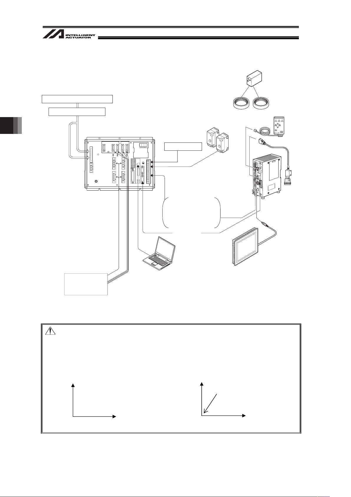
3. Coordinates·················································································································13
3.1 Coordinate Axes for Orthogonal Robot······································································· 13
4. Installation ··················································································································· 14
4.1 Wiring·························································································································· 14
4.1.1 Example of wiring layout when connecting Cognex camera ·······························14
4.1.2 Example of wiring layout when connecting Keyence camera······························ 15
4.1.3 Example of wiring layout when connecting OMRON camera······························ 16
4.2 Installing XSEL Controller PC Software······································································ 17
4.3 Installing the Camera·································································································· 18
4.3.1. Cognex Camera··································································································· 18
4.3.2 Keyence Camera ·································································································19
4.3.3 OMRON Camera·································································································· 20
5. Vision System I/F Function Setting ············································································· 21
5.1 Setting Procedure ······································································································· 21
5.2 About Parameter Change ···························································································23
5.2.1 Regarding to Value Setting ··················································································23
5.2.1.1 Binary Number ····························································································· 23
5.2.1.2 Hexadecimal Number ·················································································· 23
5.3 Communication Channel Setting ················································································24
5.3.1 When Ethernet TCP/IP Message Communication is Used··································24
5.3.2 When Standard SIO (RS232C) Channel Communication is Used ······················ 26
5.4 Communication Format Setting ·················································································· 27
5.5 Unit Conversion (pixel mm) ···················································································· 29
5.6 Coordinate Setting ······································································································ 29
5.7 Detailed Function Settings·························································································· 30

5.8 Vision System I/F adjustment ·····················································································32
5.8.1 Initial Settings for Simple Calibration
(When EZ-110XL camera is used) ·······································································33
5.8.2 When Camera Not Mounted on Robot
(When EZ-110XL is used) ····················································································37
5.8.3 When Camera Mounted on Robot
(When EZ-110XL is used) ····················································································57
5.8.4 When Camera Not Mounted on Robot
(When camera other than EZ-110XL is used)······················································77
5.8.5 When Camera Mounted on Robot
(When camera other than EZ-110XL is used)······················································85
5.9 Variance Adjustment ··································································································· 92
6. Program Construction for Operation ··········································································· 94
6.1 SEL Command············································································································94
6.1.1 SLVS (Select Vision System I/F) Command ························································94
6.1.2 GTVD (Vision System I/F Image-Capture Data Acquirement) Command ··········· 96
6.2 Outline for SEL Program Construction (Basic Frame)················································98
7. Error Treatment········································································································· 100
7.1 Common Errors for All Vision Systems ·····································································100
7.2 Simple Calibration Execution Error for EZ-110XL·····················································105
7.3 Return Code List in READ Command (SEL Language) Execution ··························109
8. Appendix··················································································································· 110
8.1 Communication Format Setting Values····································································· 110
8.2 General-purpose RS232C Port················································································· 117
8.3 Operation of High Speed Cartesian Robot (CT4) ····················································· 118
9. Change History ········································································································· 119

1
Safety Guide
“Safety Guide” has been written to use the machine safely and so prevent personal injury or
property damage beforehand. Make sure to read it before the operation of this product.
Safety Precautions for Our Products
The common safety precautions for the use of any of our robots in each operation.
No.
Operation
Description
Description
1 Model
Selection
Ɣ This product has not been planned and designed for the application
where high level of safety is required, so the guarantee of the protection
of human life is impossible. Accordingly, do not use it in any of the
following applications.
1) Medical equipment used to maintain, control or otherwise affect
human life or physical health.
2) Mechanisms and machinery designed for the purpose of moving or
transporting people (For vehicle, railway facility or air navigation
facility)
3) Important safety parts of machinery (Safety device, etc.)
Ɣ Do not use the product outside the specifications. Failure to do so may
considerably shorten the life of the product.
Ɣ Do not use it in any of the following environments.
1) Location where there is any inflammable gas, inflammable object or
explosive
2) Place with potential exposure to radiation
3) Location with the ambient temperature or relative humidity exceeding
the specification range
4) Location where radiant heat is added from direct sunlight or other
large heat source
5) Location where condensation occurs due to abrupt temperature
changes
6) Location where there is any corrosive gas (sulfuric acid or
hydrochloric acid)
7) Location exposed to significant amount of dust, salt or iron powder
8) Location subject to direct vibration or impact
Ɣ For an actuator used in vertical orientation, select a model which is
equipped with a brake. If selecting a model with no brake, the moving
part may drop when the power is turned OFF and may cause an
accident such as an injury or damage on the work piece.
2
No.
Operation
Description
Description
2 Transportation Ɣ When carrying a heavy object, do the work with two or more persons or
utilize equipment such as crane.
Ɣ When the work is carried out with 2 or more persons, make it clear who
is to be the leader and who to be the follower(s) and communicate well
with each other to ensure the safety of the workers.
Ɣ When in transportation, consider well about the positions to hold,
weight and weight balance and pay special attention to the carried
object so it would not get hit or dropped.
Ɣ Transport it using an appropriate transportation measure.
The actuators available for transportation with a crane have eyebolts
attached or there are tapped holes to attach bolts. Follow the
instructions in the instruction manual for each model.
Ɣ Do not step or sit on the package.
Ɣ Do not put any heavy thing that can deform the package, on it.
Ɣ When using a crane capable of 1t or more of weight, have an operator
who has qualifications for crane operation and sling work.
Ɣ When using a crane or equivalent equipments, make sure not to hang a
load that weighs more than the equipment’s capability limit.
Ɣ Use a hook that is suitable for the load. Consider the safety factor of the
hook in such factors as shear strength.
Ɣ Do not get on the load that is hung on a crane.
Ɣ Do not leave a load hung up with a crane.
Ɣ Do not stand under the load that is hung up with a crane.
3 Storage and
Preservation
Ɣ The storage and preservation environment conforms to the installation
environment. However, especially give consideration to the prevention
of condensation.
Ɣ Store the products with a consideration not to fall them over or drop due
to an act of God such as earthquake.
4 Installation
and Start
(1) Installation of Robot Main Body and Controller, etc.
Ɣ Make sure to securely hold and fix the product (including the work part).
A fall, drop or abnormal motion of the product may cause a damage or
injury.
Also, be equipped for a fall-over or drop due to an act of God such as
earthquake.
Ɣ Do not get on or put anything on the product. Failure to do so may
cause an accidental fall, injury or damage to the product due to a drop
of anything, malfunction of the product, performance degradation, or
shortening of its life.
Ɣ When using the product in any of the places specified below, provide a
sufficient shield.
1) Location where electric noise is generated
2) Location where high electrical or magnetic field is present
3) Location with the mains or power lines passing nearby
4) Location where the product may come in contact with water, oil or
chemical droplets

3
No.
Operation
Description
Description
(2) Cable Wiring
Ɣ Use our company’s genuine cables for connecting between the actuator
and controller, and for the teaching tool.
Ɣ Do not scratch on the cable. Do not bend it forcibly. Do not pull it. Do
not coil it around. Do not insert it. Do not put any heavy thing on it.
Failure to do so may cause a fire, electric shock or malfunction due to
leakage or continuity error.
Ɣ Perform the wiring for the product, after turning OFF the power to the
unit, so that there is no wiring error.
Ɣ When the direct current power (+24V) is connected, take the great care
of the directions of positive and negative poles. If the connection
direction is not correct, it might cause a fire, product breakdown or
malfunction.
Ɣ Connect the cable connector securely so that there is no disconnection
or looseness. Failure to do so may cause a fire, electric shock or
malfunction of the product.
Ɣ Never cut and/or reconnect the cables supplied with the product for the
purpose of extending or shortening the cable length. Failure to do so
may cause the product to malfunction or cause fire.
4 Installation
and Start
(3) Grounding
Ɣ The grounding operation should be performed to prevent an electric
shock or electrostatic charge, enhance the noise-resistance ability and
control the unnecessary electromagnetic radiation.
Ɣ For the ground terminal on the AC power cable of the controller and the
grounding plate in the control panel, make sure to use a twisted pair
cable with wire thickness 0.5mm
2
(AWG20 or equivalent) or more for
grounding work. For security grounding, it is necessary to select an
appropriate wire thickness suitable for the load. Perform wiring that
satisfies the specifications (electrical equipment technical standards).
Ɣ Perform Class D Grounding (former Class 3 Grounding with ground
resistance 100: or below).
4
No.
Operation
Description
Description
4 Installation
and Start
(4) Safety Measures
Ɣ When the work is carried out with 2 or more persons, make it clear who
is to be the leader and who to be the follower(s) and communicate well
with each other to ensure the safety of the workers.
Ɣ When the product is under operation or in the ready mode, take the
safety measures (such as the installation of safety and protection
fence) so that nobody can enter the area within the robot’s movable
range. When the robot under operation is touched, it may result in
death or serious injury.
Ɣ Make sure to install the emergency stop circuit so that the unit can be
stopped immediately in an emergency during the unit operation.
Ɣ Take the safety measure not to start up the unit only with the power
turning ON. Failure to do so may start up the machine suddenly and
cause an injury or damage to the product.
Ɣ Take the safety measure not to start up the machine only with the
emergency stop cancellation or recovery after the power failure. Failure
to do so may result in an electric shock or injury due to unexpected
power input.
Ɣ When the installation or adjustment operation is to be performed, give
clear warnings such as “Under Operation; Do not turn ON the power!”
etc. Sudden power input may cause an electric shock or injury.
Ɣ Take the measure so that the work part is not dropped in power failure
or emergency stop.
Ɣ Wear protection gloves, goggle or safety shoes, as necessary, to
secure safety.
Ɣ Do not insert a finger or object in the openings in the product. Failure to
do so may cause an injury, electric shock, damage to the product or
fire.
Ɣ When releasing the brake on a vertically oriented actuator, exercise
precaution not to pinch your hand or damage the work parts with the
actuator dropped by gravity.
5 Teaching Ɣ When the work is carried out with 2 or more persons, make it clear who
is to be the leader and who to be the follower(s) and communicate well
with each other to ensure the safety of the workers.
Ɣ Perform the teaching operation from outside the safety protection
fence, if possible. In the case that the operation is to be performed
unavoidably inside the safety protection fence, prepare the “Stipulations
for the Operation” and make sure that all the workers acknowledge and
understand them well.
Ɣ When the operation is to be performed inside the safety protection
fence, the worker should have an emergency stop switch at hand with
him so that the unit can be stopped any time in an emergency.
Ɣ When the operation is to be performed inside the safety protection
fence, in addition to the workers, arrange a watchman so that the
machine can be stopped any time in an emergency. Also, keep watch
on the operation so that any third person can not operate the switches
carelessly.
Ɣ Place a sign “Under Operation” at the position easy to see.
Ɣ When releasing the brake on a vertically oriented actuator, exercise
precaution not to pinch your hand or damage the work parts with the
actuator dropped by gravity.
* Safety protection Fence : In the case that there is no safety protection
fence, the movable range should be indicated.
5
No.
Operation
Description
Description
6 Trial
Operation
Ɣ When the work is carried out with 2 or more persons, make it clear who
is to be the leader and who to be the follower(s) and communicate well
with each other to ensure the safety of the workers.
Ɣ After the teaching or programming operation, perform the check
operation one step by one step and then shift to the automatic
operation.
Ɣ When the check operation is to be performed inside the safety
protection fence, perform the check operation using the previously
specified work procedure like the teaching operation.
Ɣ Make sure to perform the programmed operation check at the safety
speed. Failure to do so may result in an accident due to unexpected
motion caused by a program error, etc.
Ɣ Do not touch the terminal block or any of the various setting switches in
the power ON mode. Failure to do so may result in an electric shock or
malfunction.
7 Automatic
Operation
Ɣ Check before starting the automatic operation or rebooting after
operation stop that there is nobody in the safety protection fence.
Ɣ Before starting automatic operation, make sure that all peripheral
equipment is in an automatic-operation-ready state and there is no
alarm indication.
Ɣ Make sure to operate automatic operation start from outside of the
safety protection fence.
Ɣ In the case that there is any abnormal heating, smoke, offensive smell,
or abnormal noise in the product, immediately stop the machine and
turn OFF the power switch. Failure to do so may result in a fire or
damage to the product.
Ɣ When a power failure occurs, turn OFF the power switch. Failure to do
so may cause an injury or damage to the product, due to a sudden
motion of the product in the recovery operation from the power failure.
6
No.
Operation
Description
Description
8 Maintenance
and
Inspection
Ɣ When the work is carried out with 2 or more persons, make it clear who
is to be the leader and who to be the follower(s) and communicate well
with each other to ensure the safety of the workers.
Ɣ Perform the work out of the safety protection fence, if possible. In the
case that the operation is to be performed unavoidably inside the safety
protection fence, prepare the “Stipulations for the Operation” and make
sure that all the workers acknowledge and understand them well.
Ɣ When the work is to be performed inside the safety protection fence,
basically turn OFF the power switch.
Ɣ When the operation is to be performed inside the safety protection
fence, the worker should have an emergency stop switch at hand with
him so that the unit can be stopped any time in an emergency.
Ɣ When the operation is to be performed inside the safety protection
fence, in addition to the workers, arrange a watchman so that the
machine can be stopped any time in an emergency. Also, keep watch
on the operation so that any third person can not operate the switches
carelessly.
Ɣ Place a sign “Under Operation” at the position easy to see.
Ɣ For the grease for the guide or ball screw, use appropriate grease
according to the Instruction Manual for each model.
Ɣ Do not perform the dielectric strength test. Failure to do so may result in
a damage to the product.
Ɣ When releasing the brake on a vertically oriented actuator, exercise
precaution not to pinch your hand or damage the work parts with the
actuator dropped by gravity.
Ɣ The slider or rod may get misaligned OFF the stop position if the servo
is turned OFF. Be careful not to get injured or damaged due to an
unnecessary operation.
Ɣ Pay attention not to lose the cover or untightened screws, and make
sure to put the product back to the original condition after maintenance
and inspection works.
Use in incomplete condition may cause damage to the product or an
injury.
* Safety protection Fence : In the case that there is no safety protection
fence, the movable range should be indicated.
9 Modification
and Dismantle
Ɣ Do not modify, disassemble, assemble or use of maintenance parts not
specified based at your own discretion.
10 Disposal Ɣ When the product becomes no longer usable or necessary, dispose of it
properly as an industrial waste.
Ɣ When removing the actuator for disposal, pay attention to drop of
components when detaching screws.
Ɣ Do not put the product in a fire when disposing of it.
The product may burst or generate toxic gases.
11 Other Ɣ Do not come close to the product or the harnesses if you are a person
who requires a support of medical devices such as a pacemaker. Doing
so may affect the performance of your medical device.
Ɣ See Overseas Specifications Compliance Manual to check whether
complies if necessary.
Ɣ For the handling of actuators and controllers, follow the dedicated
instruction manual of each unit to ensure the safety.
7
Alert Indication
The safety precautions are divided into “Danger”, “Warning”, “Caution” and “Notice” according to
the warning level, as follows, and described in the Instruction Manual for each model.
Level Degree of Danger and Damage Symbol
Danger
This indicates an imminently hazardous situation which, if the
product is not handled correctly, will result in death or serious
injury.
Danger
Warning
This indicates a potentially hazardous situation which, if the
product is not handled correctly, could result in death or serious
injury.
Warning
Caution
This indicates a potentially hazardous situation which, if the
product is not handled correctly, may result in minor injury or
property damage.
Caution
Notice
This indicates lower possibility for the injury, but should be kept to
use this product properly.
Notice

8
Precautions in Handling
x The number of work pieces that the camera can detect in 1 shot of image capturing is as
described below:
Cognex In-Sight EZ110 8 pieces at max.
Cognex In-Sight 5000 12 pieces at max.
Keyence CV-2000 7 pieces at max.
Vision systems of Keyence other than CV-2000 and I/F applicable vision systems 12 pieces at max.
OMRON vision systems 12 pieces at max.
x Build the system with care so that the work after being captured would not get moved off the
position by an external force (vibration, air blow, crash of another work, etc.).
x If the image-capturing conditions, such as the light (diffusers), focus, diaphragm, shutter speed,
etc., are inefficient, such problems like the work not being detected or inaccurate position
detection may occur. (Please refer to the Instruction Manual for Vision System to have the
appropriate adjustments.)
x Please ask each vision system supplier for the adjustment of Vision System (detection settings,
format settings indicated for our products [refer to Section 8.1], etc.).
When using Cognex In-Sight EZ110, the sample job data is available to download from the
enclosed CD or IAI homepage. (* Please ask the distributor to have the detection settings done
for you so it suits to the work that you will use.)
x Regarding Operation of High Speed Cartesian Robot CT4
Refer to 8.3 Operation of High Speed Cartesian Robot (CT4) for the details.

9
1. Overview
Vision System I/F Function is a function to store the coordinate data
(Note 1) (Note 2)
sent from the work
directly to the position data.
When using the vision system, the specialized window in the PC software always backups the
adjustment (calibration) of coordinates of the necessary camera and robot
(Note 3)
.
(Note 1) In the existing systems, the data from Vision System needs to be treated as characters
and the user needs to convert the values to store the position data. In Vision System I/F
Function, the user does not need to convert the values, and the coordinates are directly
stored to the position data.
(Note 2) It is necessary to send the data in the format indicated by our products.
(Note 3) If conducting the dedicated calibration with EZ-110XL, the procedure of manual
alignment of the work to the robot which is necessary for the existing models will be
dramatically reduced.
This manual explains how to set up the system to utilize Vision System I/F Function.
1. Overview
2. Work Flow before Operation Start
10
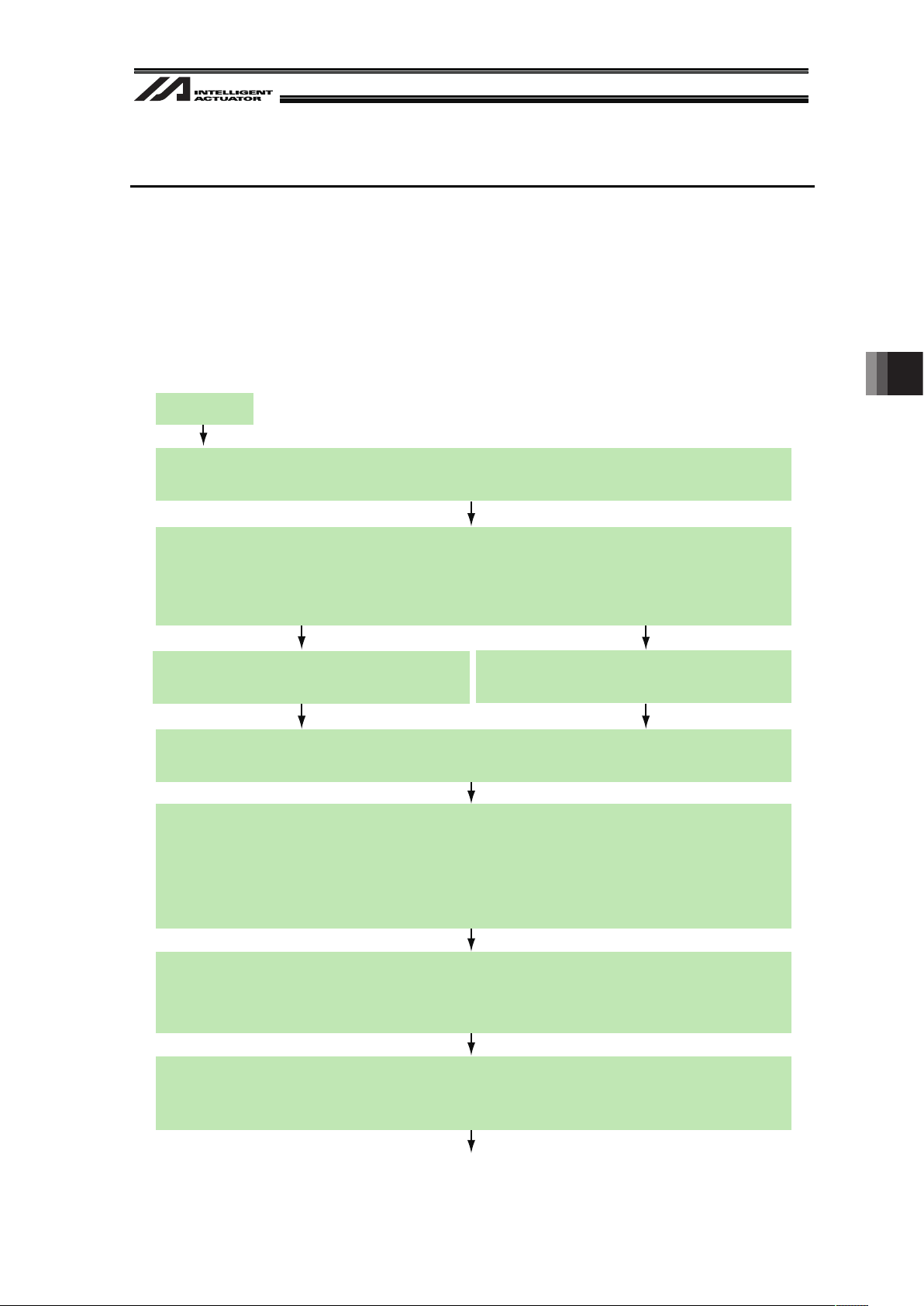
2. Work Flow before Operation Start
Note
Make sure to have the settings of the vision system such as the work detection setting and
communication setting done before having the vision system I/F function settings.
2.1 Starting Procedures
No
No
No
Yes
Check of Packed Items
Are there all the delivered items?
Do you have all the equipment listed in Section 2.2 that needs to be
prepared beforehand?
Yes
Yes
Yes
Yes
Yes
Installation and Wiring
Have the actuator and encoder installed and connected following the instructions in XSEL Controller Instruction
Manual, Actuator Instruction Manual and this manual (see Section 4).
Are the frame grounding (FG) and protection earthing (PE) conducted?
Has the noise countermeasure been taken?
Power Supply and Alarm Check
Connect the PC, put AUTO/MANU switch to “MANU” side and
turn the power on.
Is the status display showing “rdy” ?
Check of Safety Circuit
Actuator Setting
Check that the emergency stop circuit (or motor drive power cutoff
circuit) operates normally to turn off the servo.
Vision System I/F Function Setting (Refer to Section 5)
The setting details differ depending if the camera is mounted to the robot or not.
Creating Program (Refer to Section 6)
Create a program based on SEL program construction capacity.
Power-up and Operation Check
Have the program run to check the sensor input, axis data from the camera and tracking position.
Have an appropriate treatment following
the content of the status display.
[Refer to the trouble shootings in Instruction Manuals for XSEL Controller and PC
Software.]
No
Is the motor cable connected?
No
Contact the sales shop.
Connect the motor cable.
Check the emergency stop circuit.
Check the alarm content on the PC to
have an appropriate treatment if an
alarm is generated.
Write the target position to the position table.
Press the SV button in the button display for each axis in the PC
software to turn the servo on.
After the servo is on, press the HM button in the button display for
each axis to conduct a home-return operation.
Did the servo turn on and home without error?
Now, the operation adjustment is complete.
Conduct an adjustment by the system.
11
2.2 Items to Prepare Beforehand
The Vision System explained in this manual is in regard to the equipment’s operation and its
program. The equipment and components that construct the system need to be prepared
separately.
1) Vision System
Corresponding Product
(Note) Please ask each vision system supplier to have the settings on Vision System such as the work
detection setting and the output communication format indicated by our products [refer to Section
8.1].
x PIO Cable
(There are some cases that the dedicated accessary is required. Please refer to the
Instruction Manual for each Vision System.
e.g. FZ-VP, Parallel I/O cable dedicated for OMRON FZ3)
x For Ethernet Connection
LAN cable (Category 5 or higher)
Hub
x For RS232C Connection
Apply a cable that has a connector suitable for the camera controller on one end and D-sub
9-pin connector (female) on the other end (XSEL end).
[Refer to the Instruction Manual for each Vision System for the wiring on the camera controller
side.]
[Refer to the Appendix at the end for the wiring on XSEL side.]
x If Using Work Detection Sensor
Photoelectric sensor
Examples of Vision System Models
Supplier Model Interface
Cognex
In-Sight EZ-110 (EZ-110XL)
In-Sight 5000 Series
Ethernet
OMRON F210-C10 FZ3 RS232C
Keyence CV2000 CV3000 CV5000 XG-7000
Ethernet
RS232C
2. Work Flow before Operation Start
12
2) Other Requirement of IAI Products
x XSEL Controller
(Main application Version XSEL-P/Q : V1.05 or later
XSEL-R/S : V1.04 or later)
x Ethernet Board
(Option … If Ethernet is used for communication between the vision system and XSEL)
x XSEL controller PC software
(If the vision system is In-Sight EZ110 (EZ-110XL);
• XSEL-P/Q : Version V7.07.08.00 or later
• XSEL-R/S : Version V9.0.0.0 or later
(If the vision system is not In-Sight EZ110 (EZ-110XL);
• XSEL-P/Q : Version V7.06.08.00 or later
• XSEL-R/S : Version V9.0.0.0 or later
Note
When using the conveyor tracking function and the vision system I/F function at the same time, it
is not possible to have Ethernet to both of the functions as the communication interface. Connect
one of them with RS232C.
Available interface combination when using vision system
Conveyer Tracking Vision System I/F
Interface
Ethernet
Standard SIO
(RS232C)
Ethernet
Standard SIO
(RS232C)
Ethernet × ż
Conveyer
Tracking
Standard SIO
(RS232C)
ż ż
Ethernet
× ż
Vision System
I/F
Standard SIO
(RS232C)
ż ż
If the vision system is EZ-110XL and the dedicated software is used, the simple adjustment function
that enables to reduce the procedure of manual alignment in the matching process of the robot and
the vision system coordinates can be used.
When using the simple adjustment function, the work to be used in the adjustment process and a
tool to hold the work (chuck, grip, etc.) are necessary for the settings.
2. Work Flow before Operation Start
13
3. Coordinates
3.1 Coordinate Axes for Orthogonal Robot
The coordinate axes are fixed. (Refer to table below.)
Y-axis (2-axis)
X-axis (1-axis)
Rotary Axis (4-axis)
Z-axis (3-axis)
+
+
+
+
The work coordinates data received from the vision system (position information) is saved to the
position data as shown below.
No. (Name)
Axis1 (1-axis) Axis2 (2-axis) Axis3 (3-axis) Axis4 (4-axis)
Axis5 Axis6
1 ( ) 10.000 0.000 45.000
Note
x The position data of the axes that are not indicated as the valid axis pattern (All-Axes Parameter
No.1) (invalid axes) do not get updated.
x If there is an axis that is not to be used in Axis1, Axis2 and Axis4, declare the axis that uses the
position data in GRP Command.
x Ensure the applied actuators lie across each other in the right angle. Failure to do so may
disable to obtain accurate work coordinate data.
x The positive directions are premised as shown below for the robot X and Y axes coordinates.
㪯
㪰
Work X
Coordinate
ω
Work Y
Coordinate
ω
Work
T
Coordinate
ω
3. Coordinates
4. Installation
14
4. Installation
4.1 Wiring
Shown below is an example of the vision system wiring layout when each camera controller is
connected.
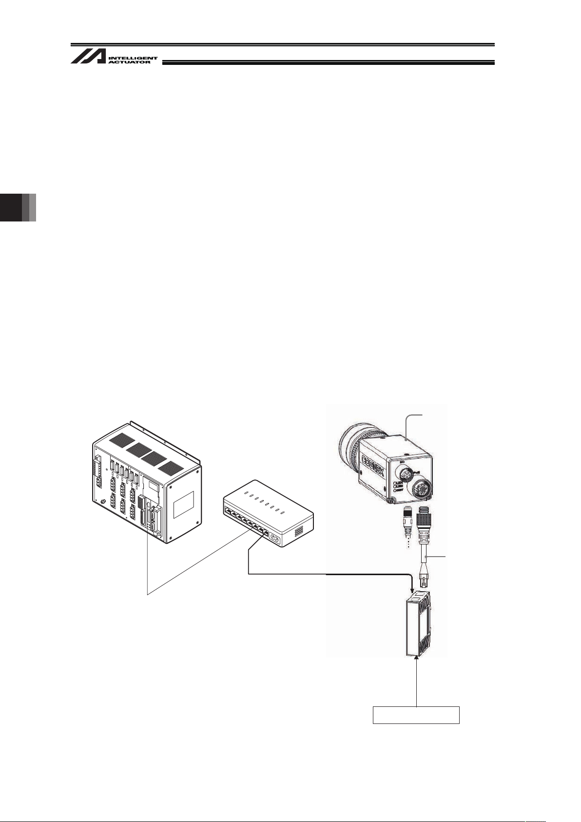
4.1.1 Example of wiring layout when connecting Cognex camera
Example for Vision System Wiring (Cognex)
Note:
• 24V I/O signal (PIO) is used for the capture command to the camera. Use the dedicated I/O
cable for the vision systems if it is equipped with a dedicated cable.
• For EZ-110XL
Set the robot axes and the vision system X-axes so they are orienting the same directions.
Robot Axes Vision System Axes
• For those other than In-Sight EZ110
Set the robot axes and the vision system axes so they are orienting the same directions.
Also, allocate the vision system origin to the bottom left of the screen.
Robot Axes Vision System Axes
Y
X
Allocate the origin to
bottom left of screen
(Utilize the spread sheet)
X
Y
X
X
Power Supply Supprtive Circuit
3-phase 200V AC to 230V power supply
+24V Power Supply
Brake and
Power Supply for I/O
Camera
Work Detection Sensor
(when applied as the
image-capture trigger)
Light
PIO Signals (2 signals)
• Camera start-up signal
(Camera → XSEL)
(Note)
• Image Capturing Command
(XSEL → Camera)
PoE Injector
Robot
+24V Power Supply
Ethernet
M Cable
PC
Hub
Power Supply Unit for
Light Equipment
(Note) The setting not to use the camera startup signal is
also available. (It is described later.)
15
4.1.2 Example of wiring layout when connecting Keyence camera
Example for Vision System Wiring (Keyence)
Note:
• 24V I/O signal (PIO) is used for the capture command to the camera. Use the dedicated I/O
cable for the vision systems if it is equipped with a dedicated cable.
• Set the robot axis and the vision system axes directions so the X-axes are orienting the same
direction and Y-axes the opposite. Also, allocate the vision system origin to the top left of the
screen.
Robot Axes Vision System Axes
Y
X
Y
X
Allocate the origin to top
left of screen
Power Supply Supprtive Circuit
PIO Signals (2 signals)
• Camera Controller
Startup Complete Signal
(Camera Controller→XSEL)
(Note 1)
• Image Capturing Command
(XSEL→Camera Controller)
Ethernet or RS232C
(Note 2)
M Cable
Robot
Monitor
Camera
PC
Hub
+
24V
3-phase 200V AC to 230V power supply
Brake and
Power Supply for I/O
Power Supply
Work Detection Sensor
(when applied as the image-capture trigger)
Light
Console
Camera Controller
Main Body
(Note 1)
(Note 2)
The setting not to use the camera controller startup signal is
also available. (It is described later.)
There is no need for a hub for RS232C connection.
Refer to the Appendix at the end for wiring on XSEL side.
Refer to the Instruction Manual for each Vision System for
wiring on camera controller side.
4. Installation
4. Installation
16
4.1.3 Example of wiring layout when connecting OMRON camera
Example for Vision System Wiring (OMRON)
Note:
• 24V I/O signal (PIO) is used for the capture command to the camera. Use the dedicated I/O
cable for the vision systems if it is equipped with a dedicated cable.
• Set the robot axes and the vision system axes so they are orienting the same directions. Also,
allocate the vision system origin to the bottom left of the screen.
Robot Axes Vision System Axes
Y
X
Y
X
Allocate the origin to
bottom left of screen
RS232C
(Note 3)
Power Supply Supprtive Circuit
M Cable
Robot
Monitor
Camera
PC
24V
+
3-phase 200V AC to 230V power supply
Power Supply
Light
Console
Camera Controller
Main Body
Work Detection Sensor
(when applied as the image-capture trigger)
Power Supply Unit for Light Equipment
(Pin Input)
PIO Signals (2 signals)
(Note1)
• Camera Controller
Startup Complete Signal
(Camera Controller→XSEL)
(Note 2)
• Image Capturing Command
(XSEL→Camera Controller)
Brake and
Power Supply for I/O
(Note 1)
(Note 2)
(Note 3)
There are some cases that the dedicated parallel I/O
cable is required.
[Refer to the Instruction Manual for Vision System]
The setting not to use the camera controller startup signal is
also available. (It is described later.)
Refer to the Appendix at the end for wiring on XSEL side.
Refer to the Instruction Manual for each Vision System for
wiring on camera controller side.

17
4.2 Installing XSEL Controller PC Software
Refer to the Instruction Manual for XSEL Controller PC Software for how to install XSEL Controller
PC Software and how to implement the initial settings.
4. Installation
4. Installation
18
4.3 Installing the Camera
4.3.1 Cognex Camera
The camera products of Cognex Corporation applicable to the vision system are limited only to
“In-Sight EZ110 (EZ110-XL)” and “In-Sight 5000 Series”.
The way to install the camera can be selected from mounting on the robot and fixing on the
equipment.
Install the camera considering how to use it.
Lighting equipment is separately required when capturing an image with the camera.
It is possible to identify the following numbers of work pieces in 1 shot of image capturing.
• In-Sight EZ110 (EZ110-XL) : 8 pieces at max.
• In-Sight 5000 Series : 12 pieces at max.
Refer to the following Cognex instruction manuals for the details of how to connect the devices.
• In-Sight EZ110 (EZ110-XL) : “In-Sight EZ Series Vision System Installation Guide”
• In-Sight 5000 Series : “In-Sight 5000 Series Vision System Installation Guide”
“CIO-1400C I/O Expansion Module Instruction Manual”
Shown below is an example of the basic construction of Vision System with one unit of camera
connected.
XSEL P/Q Controller Main Unit
Hub
100V AC Power Supply
PoE Injector
Camera
Camera
Cable
Example for Cognex Camera Controller Basic Construction
19
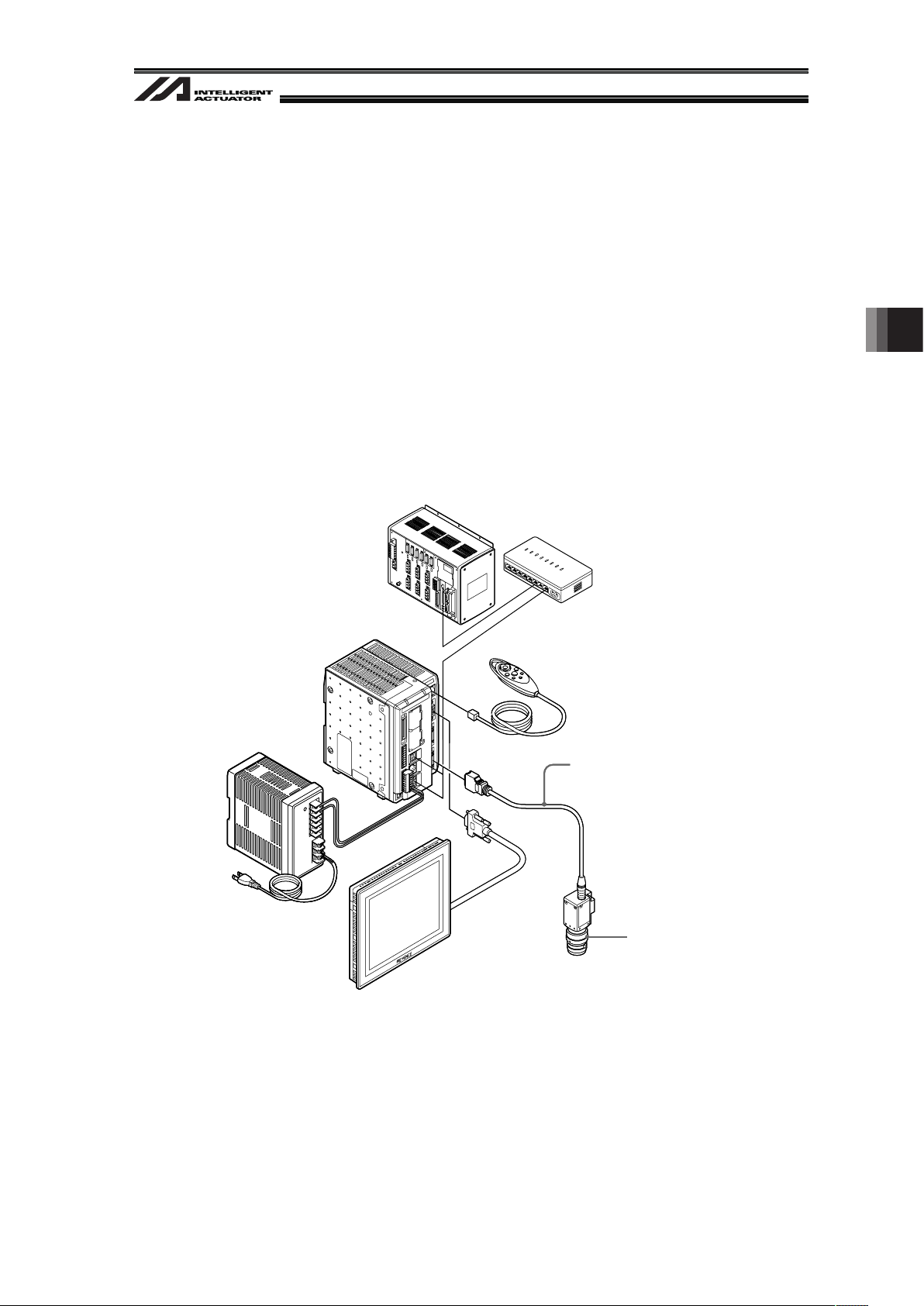
4.3.2 Keyence Camera
The camera manufactured by Keyence Corporation that is applicable for Vision System is
“In-CV-2000/CV-3000/CV-5000/XG-7000” only.
The way to install the camera can be selected from mounting on the robot and fixing on the
equipment.
Install the camera considering how to use it.
Lighting equipment is separately required when capturing an image with the camera.
12 pieces (0 to 7 pieces for CV-2000) of works can be identified at maximum in 1 shot.
Shown below is an example of the basic construction of Vision System with one unit of camera
connected.
XSEL P/Q Controller Main Unit or Hub, etc.
Camera Cable
Camera Controller Monitor
24V DC Power Supply
SD Card
(Inserted to SD1 Slot
on the main unit of controller)
Lens
Camera
Camera Controller
Main Body
Console
Example for Keyence Camera Controller Basic Construction
4. Installation
4. Installation
20
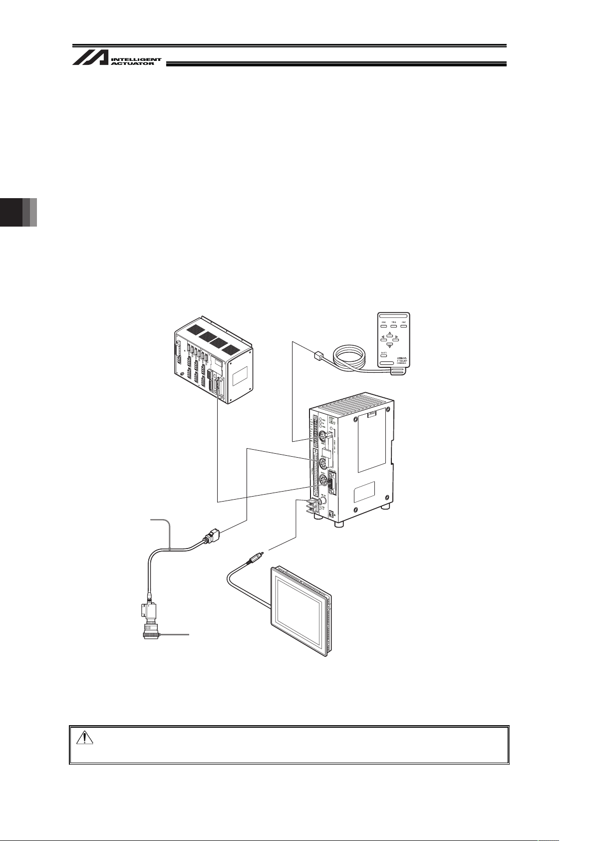
4.3.3 OMRON Camera
The camera manufactured by OMRON Corporation that is applicable for Vision System is OMRON
Camera Controller “F210-C10 or FZ3” only.
The way to install the camera can be selected from mounting on the robot and fixing on the
equipment.
Install the camera considering how to use it.
Lighting equipment is separately required when capturing an image with the camera.
12 pieces of works can be identified at maximum in 1 shot.
Shown below is an example of the basic construction of Vision System with one unit of camera
connected.
Example for OMRON Camera Controller Construction(for F210-C10)
Note:
USB and Ethernet are not supported for the camera connection.
XSEL P/Q
Controller Main Body
SD Card
(Inserted to SD1 Slot
on the main unit of controller)
Monitor
Camera
Camera Cable
Console
Camera Controller
Main Body
Lens
(Pin Input)
21
5. Vision System I/F Function Setting
Refer to the materials such as the Instruction Manual for the connected camera controller for the
details of how to set up on the camera controller side.
This manual explains how to set up the system to utilize the vision system I/F function.
The setting is to be conducted using XSEL Controller, PC software and the setting tool of each
vision system.
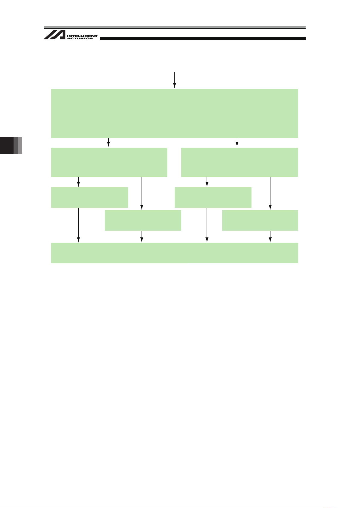
5.1 Setting Procedure
Continues to the next page
RS232C Channel Setting (setting on XSEL)
Follow Section 5.3.2.
Which of the following is used for the communication between the vision system (camera)
and XSEL Controller?
1) Ethernet 2) RS232C
(Cognex or Keyence) (OMRON or Keyence)
Start up the PC software and connect with XSEL Controller.
Start up the vision system setting tool and connect with the vision system.
Supplier Setting of Connected Camera (setting on XSEL)
Set the supplier name of the connected camera following Section 5.4.
Vision System Check and Communication Setting (setting on vision system)
Perform the necessary settings such as image setting, tool setting, inspection, input,
output and communication with using the vision system setting tool.
Set the unit of the output of the coordinate data from the vision system to mm except for
when using the dedicated calibration with EZ-110XL. (Refer to Section 5.5)
Coordinate Setting (setting on vision system)
Set the coordinate origin of the vision system following Section 5.6.
This setting is not necessary when using the dedicated calibration with EZ-110XL.
Detailed Function Settings (setting on XSEL)
Set the image-capture command input port number and other necessary numbers
following Section 5.7.
Ethernet Channel Setting (setting on XSEL)
Follow Section 5.3.1.
Setting Start
5. Vision System I/F Function Setting
5. Vision System I/F Function Setting
22
Continued from the previous page
Perform the adjustment
following Section 5.8.3.
Perform the adjustment
following Section 5.8.2.
Adjustment of Vision System Coordinates and Robot Coordinates
(setting on XSEL and Vision System)
Which vision system of the following is to be used?
1) Cognex 2) Other (except for 1))
EZ-110XL
In which way the camera is installed?
1) On the robot 2) Not on the robot
(Fix on equipment)
In which way the camera is installed?
1) On the robot 2) Not on the robot
(Fix on equipment)
Perform the adjustment
following Section 5.8.1.
Perform the adjustment
following Section 5.8.4.
Program Edit (setting on XSEL)
Create the program by following the SEL Program construction guideline.
23
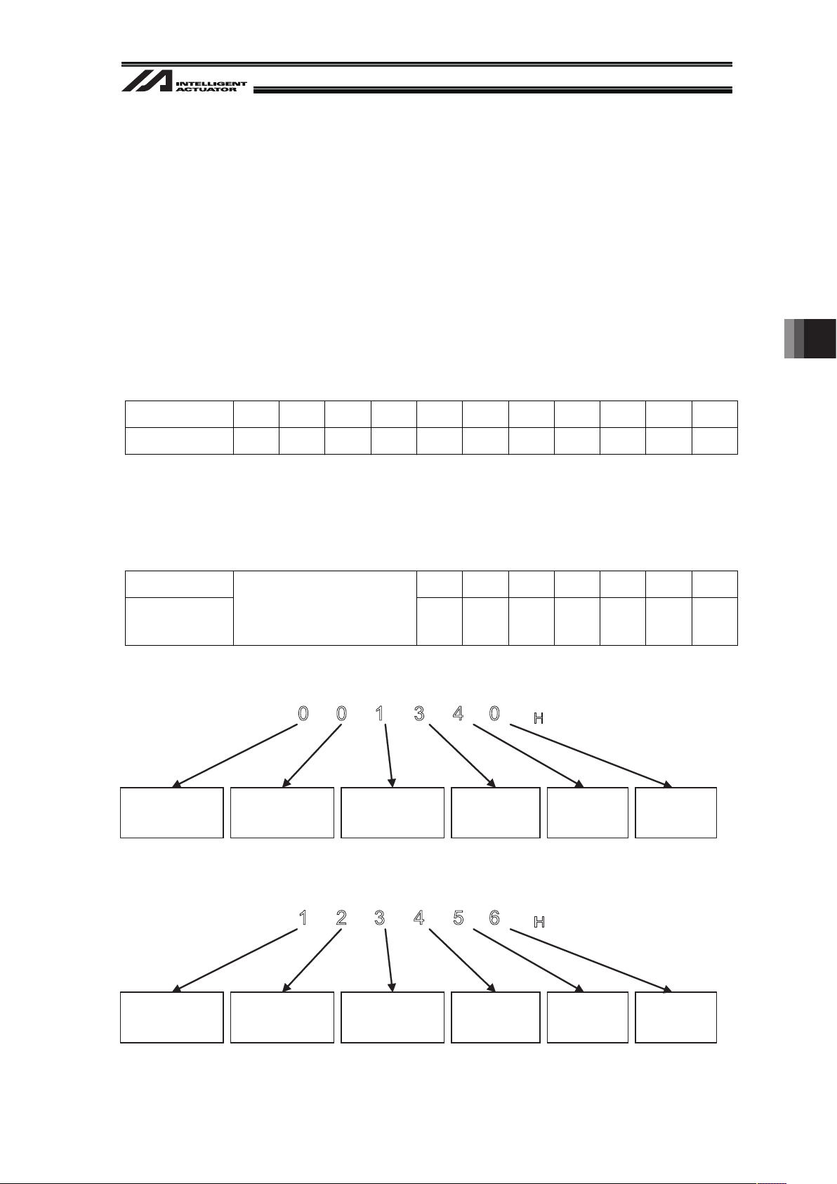
5.2 About Parameter Change
5.2.1 Regarding to Value Setting
If the last digit of the set value is H, set with hexadecimal number.
Refer to the following.
Input the value of hexadecimal number transformed from the binary number.
5.2.1.1 Binary Number
Binary number expresses a numeral figure with using 2 numbers, 0 and 1.
The number increases in the order of 0, 1, and then the number of digit increases, and goes 10, 11
…
Decimal Number 0 1 2 3 4 5 6 7 8 9 10
Binary Number 0 1 10 11 100 101 110 111 1000 1001 1010
5.2.1.2 Hexadecimal Number
Hexadecimal number expresses a numeral figure with using numbers from 0 to 9 and alphabets
from A to F. The number increases in the order of 0, 1, 2, 3, 4, 5, 6, 7, 8, 9, A, B,C, D, E, F, and then
the number of digit increases, and goes 10, 11, …
Decimal Number 10 11 12 13 14 15 16
Hexadecimal
Number
0 to 9
(Same for decimal and
hexadecimal numbers)
A B C D E F 10
Example 1 : 001340
H
Bit
20-23
0000
Bit
16-19
0000
Bit
12-15
0001
Bit
8-11
0011
Bit
4-7
0100
Bit
0-3
0000
0 0 1 3 4 0
H
Example 2 : 123456
H
Bit
20-23
0001
Bit
16-19
0010
Bit
12-15
0011
Bit
8-11
0100
Bit
4-7
0101
Bit
0-3
0110
1 2 3 4 5 6
H
5. Vision System I/F Function Setting
5. Vision System I/F Function Setting
24
5.3 Communication Channel Setting
Either RS232C (standard for XSEL), Ethernet Communication Board
(*1)
(option for XSEL-P/Q type)
or EtherNet/IP Communication Board (option for XSEL-R/S type) is used for the vision system I/F
function.
*1 Not applicable for XSEL-R/S
If using Ethernet, follow the instructions in Section 5.3.1 to perform the settings.
If using RS232C, follow the instructions in Section 5.3.2 to perform the settings.
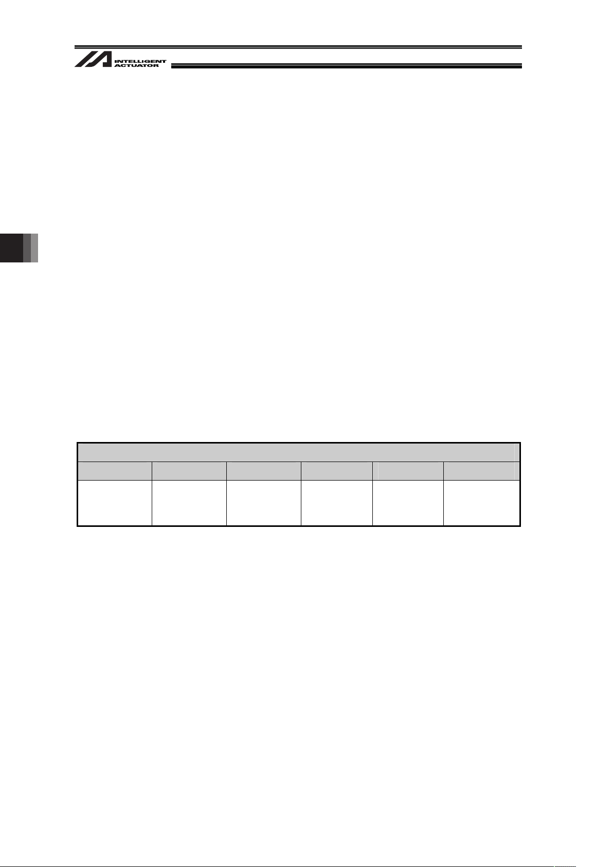
5.3.1 When Ethernet TCP/IP Message Communication is Used
When using the Ethernet TCP/IP message communication (Cognex or Keyence), set the XSEL
parameters in the right order.
[Setting 1] Ethernet TCP/IP Message Communication Attribute [compulsory] (I/O Parameter
No.124)
Set the Ethernet TCP/IP message communication attribute in I/O Parameter No.124.
Select one channel from channels 31 to 34 and set it as the client (setting value = 1).
(Note) When using Cognex In-Sight EZ110 (EZ-110XL), set the parameter to;
I/O Parameter No.124 = 003100
H
I/O Parameters No.124
Bit 20-23 Bit 16-19 Bit 12-15 Bit 8-11 Bit 4-7 Bit 0-3
Free-for-User
Channel 34
Set Value=1
Free-for-User
Channel 33
Set Value=1
Free-for-User
Channel 32
Set Value=1
Free-for-User
Channel 31
Set Value=1
Set Value=0 Set Value=0
Set Value = 0 : Channel not in use
Set Value = 1 : Set X-SEL as the client
Set Value = 3 : Set X-SEL as the server
(Example 1) When using the channel 31 for Vision System I/F
I/O Parameter No.124 = 000100
H
(Example 2) When using the channel 32 for Vision System I/F and 31 for another program
(server) (and not using 33 and 34)
I/O Parameter No.124 = 001300
H
Loading...