

Page 1
X-SEL Controller
JX/KX Type
Operation Manual
Seventh Edition
Page 2

Page 3

and 60.
CAUTION
Operator Calls Regarding Low Battery Voltage
This controller uses the following backup batteries to retain data after the power is cut off:
[1] System-memory backup battery
For retention of position data, global variables/flags, error lists, strings, etc.
[2] Absolute-encoder backup battery
For retention of encoder rotation data.
Each battery is of no n-rechargeable type, so u nles s t h e bat tery is replaced befor e its l if e is f ul ly consumed,
the battery voltage will eventually drop to a level where data can no longer be retained after the power is
cut off.
(The specific life of each battery varies depending on the operating time.)
Once data is lost, the controller cannot operate properly the next time the power is turned on, in which
case additional time will be required for recovery operation.
(Reference)
System-memory backup battery --- A voltage low warning will generate when the voltage drops to
approx. 2.6 V from the rated voltage of 3.0 V, and data will be lost
once the voltage drops to approx. 2.3 V.
Absolute-encoder backup battery --- A voltage low warning will generate when the voltage drops to
approx. 3.2 V from the rated voltage of 3.6 V, and data will be lost
once the voltage drops to approx. 2.7 V.
In view of the above, this controller provides functions that allow voltage low warnings for the two batteries
to be output from I/O ports.
Output port No. 313 is assigned as the output of voltage low warning for system-memory backup battery.
Output port No. 314 is assigned as the output of voltage low warning for absolute-encoder backup
battery.
These warning output functions are available on controllers shipped on or after May 16, 2005. On
controllers shipped before this date, the functions can be enabled by setting “1” in I/O parameter Nos. 59
It is requested that the aforementioned functions be used to prevent unnecessary problems caused by low
battery voltage (consumption of battery life).
In particular, design engineers responsible for coordinating the system components should reflect, in the
design specifications, appropriate means for warning the operator using the I/O output signals utilizing the
above functions. Electrical design engineers should ensure that such means are reflected in the electrical
circuits.
For the battery replacement procedure, refer to the applicable section in the Operation Manual.
It is recommended that the latest data be constantly backed up to a PC in case of low system-memory
backup battery voltage or unexpected controller failure.
Page 4

Page 5
Danger
Safety Precautions
Please read the information in “Safety Precautions” carefully before selecting a model and using the
product.
The precautions described below are designed to help you use the product safely and avoid bodily injury
and/or property damage.
Directions are classified as “danger,” “warning,” “caution” and “note,” according to the degree of
risk.
Danger
Failure to observe the instruction will res ult in an imminent danger leading to
death or serious injury.
Warning
Caution
Note
Failure to observe the instruction may result in death or serious injury.
Failure to observe the instruction may result in injury or property damage.
The user should take heed of this information to ensure the proper use of the
product, although failure to do so will not result in injury.
This product has been designed and manufactured as a component for use in general industrial
machinery.
Devices must be selected and handled by a system designer, personnel in charge of the actual operation
using the product or similar individual with sufficient knowledge and experience, who has read both the
catalog and operation manual (particularly the “Safety Precautions” section). Mishandling of the product
poses a risk.
Please read the operation manuals for all devices, including the main unit and controller.
It is the user’s respo ns ib il ity to v er ify and determine the c ompatibility of this pr odu c t with the us er’s system,
and to use them properly.
After reading the catalog, operation manual and other materials, be sure to keep them in a convenient
place easily accessible to the personnel using this product.
When transferring or loaning this product to a third party, be sure to attach the catalog, operation manual
and other materials in a conspicuous location on the product, so that the new owner or user can
understand its safe and proper use.
The danger, warning and caution directions in this “Safety Precauti ons” do not cover every possible case.
Please read the catalog and operation manual for the given device, particularly for descriptions unique to it,
to ensure its safe and proper handling.
[General]
Do not use this product for the following applications:
1. Medical equipment used to maintain, control or otherwise affect human life or physical health
2. Mechanisms and machinery designed for the purpose of moving or transporting people
3. Important safety parts of machinery
This product has not been planned or designed for applications requiring high levels of safety. Use
of this product in such applications may jeopardize the safety of human life. The warranty covers
only the product as it is delivered.
Page 6

Warning
[Installation]
Do not use this product in a place exposed to ignitable, inflammable or explosive substances. The
product may ignite, burn or explode.
Avoid using the product in a place where the main unit or controller may come in contact with water or
oil droplets.
Never cut and/or reconnect the cables supplied with the product for the purpose of extending or
shortening the cable length. Doing so may result in fire.
[Operation]
If you are using a pace maker or other mechanical implant, do not come within one meter of the
product. The strong magnetic field generated by the product may cause the pace maker, etc., to
malfunction.
Do not pour water onto the product. Spraying water over the product, washing it with water or using it
in water may cause the product to malfunction, resulting in injury, electric shock, fire, etc.
[Maintenance, Inspection, Repair]
Never modify the product. Unauthorized modification may cause the product to malfunction, resulting in
injury, electric shock, fire, etc.
Do not disassemble and reassemble the components relating to the basic structure of the product or its
performance and function. Doing so may result in injury, electric shock, fire, etc.
[General]
Do not use the product outside the specifications. Using the product outside the specifications may
cause it to fail, stop functioning or sustain damage. It may also significantly reduce the service life of
the product. In particular, observe the maximum loading capacity and speed.
[Installation]
If the machine will stop in the case of system problem such as emergency stop or power failure, design
a safety circuit or other device that will prevent equipment damage or injury.
Be sure to provide Class D grounding for the controller and actuator (formerly Class 3 grounding:
Grounding resistance at 100 Ω or less). Leakage current may cause electric shock or malfunction.
Before supplying power to and operating the product, always check the operation area of the
equipment to ensure safety. Supplying power to the product carelessly may cause electric shock or
injury due to contact with the moving parts.
Wire the product correctly by referring to the operation manual. Securely connect the cables and
connectors so that they will not be disconnected or come loose. Failure to do so may cause the
product to malfunction or cause fire.
[Operation]
Do not touch the terminal block or various switches while the power is supplied to the product. Failure
to observe this instruction may result in electric shock or malfunction.
Before operating the moving parts of the product by hand (for the purpose of manual positioning, etc.),
confirm that the servo is turned off (using the teaching pendant). Failure to observe this instruction may
result in injury.
The cables supplied with the product are flexible, but they are not robot cables. Do not store the cables
in a movable cable duct (cable track , etc.) that bends more than the specified bending radius.
Do not scratch the cables. Scratching, forcibly bending, pulling, winding, crushing with heavy object or
pinching a cable may cause it to leak current or lose continuity, resulting in fire, electric shock,
malfunction, etc.
Page 7

Caution
If the product is generating heat, smoke or a strange smell, turn off the power immediately. Continuing
to use the product may result in product damage or fire.
If any of the internal protective devices (alarms) of the product has actuated, turn off the power
immediately. Continuing to use the product may result in product damage or injury due to malfunction.
Once the power supply is cut off, investigate and remove the cause and then turn on the power again.
If the LEDs on the product do not illuminate after turning on the power, turn off the power immediately.
The protective device (fuse, etc.) on the live side may remain active. Request repair to the IAI sales
office from which you purchased the product.
[Maintenance, Inspection, Repair]
Before conducting maintenance/inspection, parts replacement or other operations on the product,
completely shut down the power supply. At this time, take the following measures:
1. Display a sign that reads, “WORK IN PROGRESS. DO NOT TURN ON POWER” at a conspicuous
place, in order to prevent a person other than the operator from accidentally turning on the power
while the operation is working.
2. When two or more operators are to perform maintenance/inspection together, always call out every
time the power is turned on/off or an axis is moved in order to ensure safety.
[Disposal]
Do not throw the product into fire. The product may burst or generate toxic gases.
[Installation]
Do not use the product under direct sunlight (UV ray), in a place exposed to dust, salt or iron powder,
in a humid place, or in an atmosphere of organic solvent, phosphate-ester machine oil, sulfur dioxide
gas, chlorine gas, acids, etc. The product may lose its function over a short period of time, or exhibit a
sudden drop in performance or its service life may be significantly reduced.
Do not use the product in an atmosphere of corrosive gases (sulfuric acid or hydrochloric acid),
inflammable gases or ign ita ble liquids. Rust may form and reduce the structural strength or the motor
may ignite or explode.
When using the product in any of the places specified below, provide a sufficient shield. Failure to do
so may result in malfunction:
1. Place where large current or high magnetic field is present
2. Place where welding or other operations are performed that cause arc discharge
3. Place subject to electrostatic noise
4. Place with potential exposure to radiation
Install the main unit and controller in a place subject to as little dust as possible. Installing them in a
dusty place may result in malfunction.
Do not install the product in a place subject to large vibration or impact (4.9 m/s2 or more). Doing so
may result in the malfunctioning of the product.
Provide an emergency-stop device in a readily accessible position so the device can be actuated
immediately upon occurrence of a dangerous situation during operation. Lack of such device in an
appropriate position may result in injury.
Provide sufficient maintenance space when installing the product. Routine inspection and maintenance
cannot be performed without sufficient space, which will eventually cause the equipment to stop or the
product to sustain damage.
Do not hold the moving parts of the product or its cables during installation. It may result in injury.
Always use IAI’s genuine cables for connection between the controller and the actuator. Also use IAI’s
genuine products for the key component units such as the actuator, controller and teaching pendant.
Page 8

Note
Others
Before installing or adjusting the product or performing other operations on the product, display a sign
that reads, “WORK IN PROGRESS. DO NOT TURN ON POWER.” If the power is turned on
inadvertently, injury may result due to electric shock or sudden activation of an actuator.
[Operation]
Turn on the power to individual equipment one by one, starting from the equipment at the highest level
in the system hierarchy. Failure to do so may cause the product to start suddenly, resulting in injury or
product damage.
Do not insert a finger or object in the openings in the product. It may cause fire, electric shock or injury.
Do not bring a floppy disk or other magnetic media within one meter of the product. The magnetic field
generated by the magnet may destroy the data in the floppy disk, etc.
[Maintenance, Inspection, Repair]
When the power was turned off and the cover was opened to replace the battery, etc., do not touch the
condenser terminal in the product immediately after the power was turned off (within 30 seconds).
Residual voltage may cause electric shock.
Do not touch the terminals when performing an insulation resistance test. Electric shock may result.
(Do not perform any withstand voltage tes t, since the pr oduct uses DC vol tag e.)
[General]
If you are planning to use the product under a condition or environment not specified in the catalogs
and operation manual, or in an application requiring strict safety such as aircraft facility, combustion
system, entertainment machine, safety device or other equipment having significant impact on human
life or property, design operating ranges with sufficient margins from the ratings and design
specifications or provide sufficient safety measures such as fail-safes. Whatever you do, always
consult IAI’s sales representative.
[Installation]
Do not place objects around the controller that will block airflows. Insufficient ventilation may damage
the controller.
Do not configure a control circuit that will cause the load to drop in case of power failure. Configure a
control circuit that will prevent the table or load from dropping when the power to the machine is cut off
or an emergency stop is actuated.
[Installation, Operation, Maintenance]
When handling the product, wear protective gloves, protective goggles, safety shoes or other
necessary gear to ensure safety.
[Disposal]
When the product becomes no longer usable or necess ar y, dispose of it proper l y as an indus tria l was te.
IAI shall not be liable whatsoever for any loss or damage ari si ng fro m a fail ure t o
observe the items specified in “Safety Precautions.”
Page 9

Caution
1. Do not let the cable flex at a single point.
4. Do not let the cable receive a turning force at a
5. When fixing the cable, provide a moderate slack
Steel band
Bundle loosely.
Do not use a spiral tube
Prohibited Handling of Cables
When designing an application system using actuators and controllers, incorrect wiring or connection of
each cable may cause unexpected problems such as a disconnected cable or poor contact, or even a
runaway system. This section explains prohibited handling of cables. Read the information carefully to
connect the cables properly.
Ten Rules for Handling Cables (Must be O bse r ved!)
2. Do not let the cable bend, kink or twist.
single point.
Use a curly
cable.
(piano wire)
3. Do not pull the cable with a strong force.
and do not tension it too tight.
6. Do not pinch, drop a heavy object onto or cut the
cable.
where the cable flexes
frequently.
Page 10

8. Do not cause the cables to occupy more than
9. Do not lay signal lines together with circuit lines
Cable
Cable track
Power line
Signal lines (flat cable)
Duct
Cover
Protective layer
Signal line (copper + tin)
7. Do not let the cable got tangled or kinked in a cable track or flexible tube. When bundling the cable,
keep a certain degree of flexibility (so that the cable will not become too taut when bent).
60% of the space in the cable track.
that create a strong electric field.
10. Always use a robot cable
if the cable is likely to flex significantly.
[Standard structure of cable]
The standard structure of
cable will vary depending on
the manufacturer and t ype of
cable.
Shield
Absorbing material (When the
cable is bent, this material is
crushed by the surrounding signal
lines to maintain the shape of the
signal lines.)
� Need for Robot Cables
A cable connected to a moving part of an actuator system will inevitably receive repeated bending loads at
the base of the cable. As a result, the cores in the cable may break over time. To minimize the risk of
cable breakage, we strongly recom mend that a robot cable
offering significantly higher flexibility be used
in this type of application.
Page 11

Caution
Caution
Before Use
Caution
1. Be sure to read this operation manual to ensure the proper use of this product.
2. Unauthorized use or reproduction of a part or all of this operation manual is prohibited.
3. Always handle or operate the product in manners specified in this operation manual, by assuming that
whatever is not specified herein is not feasible. The warranty does not cover any defect arising from a
handling or operation not specif ied in this opera tio n manua l.
4. The information contained in this operation manual is subject to change without notice for the purpose
of modification and improvement.
* If you have purchased PC software:
Always back up the parameters after installing the product or changing the parameter settings.
5. The specifications in this manual may not apply to a custom product.
Action to Be Taken in Case of Emergency
If this product is found to be in a dangerous condition, immediately turn off all power switches of the
main unit and connected equipment or immediately disconnect all power cables from the outlets.
(“Dangerous condition” refers to a situation where the product is generating abnormal heat or smoke or
has ignited and a fire or danger to human health is anticipated.)
Page 12

Table of Contents
Table of Contents
Introduction ...................................................................................................................... 1
Part 1 Installation ........................................................................................................ 2
Chapter 1 Safety Precautions ............................................................................................................... 2
Chapter 2 Warranty Period and Scope of Warranty ............................................................................. 3
Chapter 3 Installation Environment and Noise Measures .................................................................... 4
Chapter 4 Name and Function of Each Part ......................................................................................... 8
1. Front View of Controller .......................................................................................................... 8
2. Explanation of Codes Displayed on the Panel Window ....................................................... 18
Chapter 5 Specifications ..................................................................................................................... 20
1. Controller Specifications ....................................................................................................... 20
2. External I/O Specifications ................................................................................................... 22
3. Power-Source Capacity and Heat Output of the Controller ................................................. 26
4. External Dimensions ............................................................................................................ 27
Chapter 6 System Setup ..................................................................................................................... 29
1. Connection Method of Controller and Robot (KX Type) ....................................................... 29
2. I/O Connection Diagram ....................................................................................................... 31
3. I/O Flat Cable ....................................................................................................................... 33
Chapter 7 Maintenance ...................................................................................................................... 34
Part 2 Operation ........................................................................................................ 41
Chapter 1 Operation ........................................................................................................................... 41
1. Starting a Program by Auto-Start via Parameter Setting ...................................................... 42
2. Starting via External Signal Selection .................................................................................. 43
3. Drive-Source Recovery Request and Operation-Pause Reset Request ............................. 45
Part 3 Controller Data Structure ................................................................................ 46
Chapter 1 How to Save Data .............................................................................................................. 47
1. Factory Settings: When the System-Memory Backup Battery is Used ................................ 47
2. When the System-Memory Backup Battery is Not Used ..................................................... 48
3. Points to Note ....................................................................................................................... 49
Chapter 2 X-SEL Language Data (IX-Series Controller) .................................................................... 50
1. Values and Symbols Used in SEL Language ....................................................................... 50
2. Position Part ......................................................................................................................... 63
3. Command Part ..................................................................................................................... 64
Page 13

Table of Contents
Part 4 Commands ..................................................................................................... 66
Chapter 1 List of SEL Language Command Codes ........................................................................... 66
Chapter 2 Explanation of Commands ................................................................................................. 78
1. Commands ........................................................................................................................... 78
Chapter 3 Key Characteristics of Horizontal Articulated Robot Operation ....................................... 234
1. CP Operation and PTP Operation ...................................................................................... 234
2. Arm System ........................................................................................................................ 237
3. Coordinate System ............................................................................................................. 245
4. Simple Interference Check Zone ........................................................................................ 255
5. Soft Limits ........................................................................................................................... 258
Chapter 4 Key Characteristics of Actuator Control Commands and Points to Note ......................... 262
1. Continuous Movement Commands
[P A TH, PSPL, CIR2, ARC2, CIRS, ARCS, ARCD, ARCC, CIR, ARC] ............................... 262
2. PATH/PSPL Commands ..................................................................................................... 264
3. CIR/ARC Commands ......................................................................................................... 264
4. CIR2/ARC2/ARCD/ARCC Commands ............................................................................... 264
Chapter 5 Palletizing Function .......................................................................................................... 265
1. How to Use ......................................................................................................................... 265
2. Palletizing Setting ............................................................................................................... 265
3. Palletizing Calculation ........................................................................................................ 271
4. Palletizing Movement ......................................................................................................... 272
5. Program Examples ............................................................................................................. 274
Chapter 6 Pseudo-Ladder Task ........................................................................................................ 278
1. Basic Frame ....................................................................................................................... 278
2. Ladder Statement Field ...................................................................................................... 279
3. Points to Note ..................................................................................................................... 279
4. Program Example ............................................................................................................... 280
Chapter 7 Multi-Tasking .................................................................................................................... 281
1. Difference from a Sequencer ............................................................................................. 281
2. Release of Emergency Stop ............................................................................................... 282
3. Program Switching ............................................................................................................. 283
Page 14

Table of Contents
Appendix...................................................................................................................... 284
Expansion I/O Board (Optional)............................................................................................... 284
Expanded SIO Specification (Optional) ................................................................................... 285
List of Parameters ................................................................................................................... 291
1. I/O Parameters ................................................................................................................. 292
2. Parameters Common to All Axes ..................................................................................... 302
3. Axis-Specific Parameters ................................................................................................. 304
4. Driver Card Parameters ................................................................................................... 308
5. Encoder Parameters ........................................................................................................ 314
6. I/O-Slot Card Parameters ................................................................................................ 315
7. Other Parameters ............................................................................................................ 316
8. Manual Operation Types .................................................................................................. 321
9. Use Examples of Key Parameters ................................................................................... 322
Error Level Control .................................................................................................................. 326
Error List ................................................................................................................................ 328
Trouble Report Sheet .............................................................................................................. 356
Page 15

Page 16

Page 17
1
Introduction
hours Stopped hours Operating
hours Operating
+
Model
Series
Controller
IX actuator
Standard I/O
specification
Slot 1
Slot 2
Slot 3
Slot 4
Expanded I/O specification (Note 1)
I/O flat cable
Supply
(Compact type)
purpose, global,
(Standard type)
No cable
Introduction
Thank you for purchasing the X-SEL IX-Series Controller.
Inappropriate use or handling will prevent this product from demonstrating its full function and may even cause
unexpected failure or result in a shortened service life. Please read this manual carefully, and handle the
product with due care and operate it correctly. Keep this manual in a safe place and reference relevant items
when needed.
The IX-Series Controller you have purchased is a new-generation controller that uses an advanced version of
the proven, innovative “SEL” language to perform a range of high functions such as multi-tasking, sequencerless operation, palletizing function and pseudo-sequence function.
Actuator duty
IAI recommends that our actuators be used at a duty of 50% or less in view of the relationship of service life
and accuracy. The duty is calculated by the formula below:
Duty (%) =
After turning off the main power, be sure to wait for at least 5 seconds before turning it on.
Any shorter interval may generate “E88: Power system error (Other).”
Do not plug in/out the connectors while the power is still supplied to the controller. Doing so may result in
malfunction.
Do not move the robot arms while the main controller power is still starting. An error, such as “C6C:
Movement error during absolute data acquisition” or “C70: Absolute coordinate non-confirmation error,” may
generate.
Read the operation manual for each actuator. If you have purchased our optional PC software and/or
teaching pendant, read the respective operation manuals, as well.
* Utmost effort has been made to ensure that the information contained in this manual is true and correct.
However, should you find any error or if you have any comment regarding the content, please contact IAI.
X 100
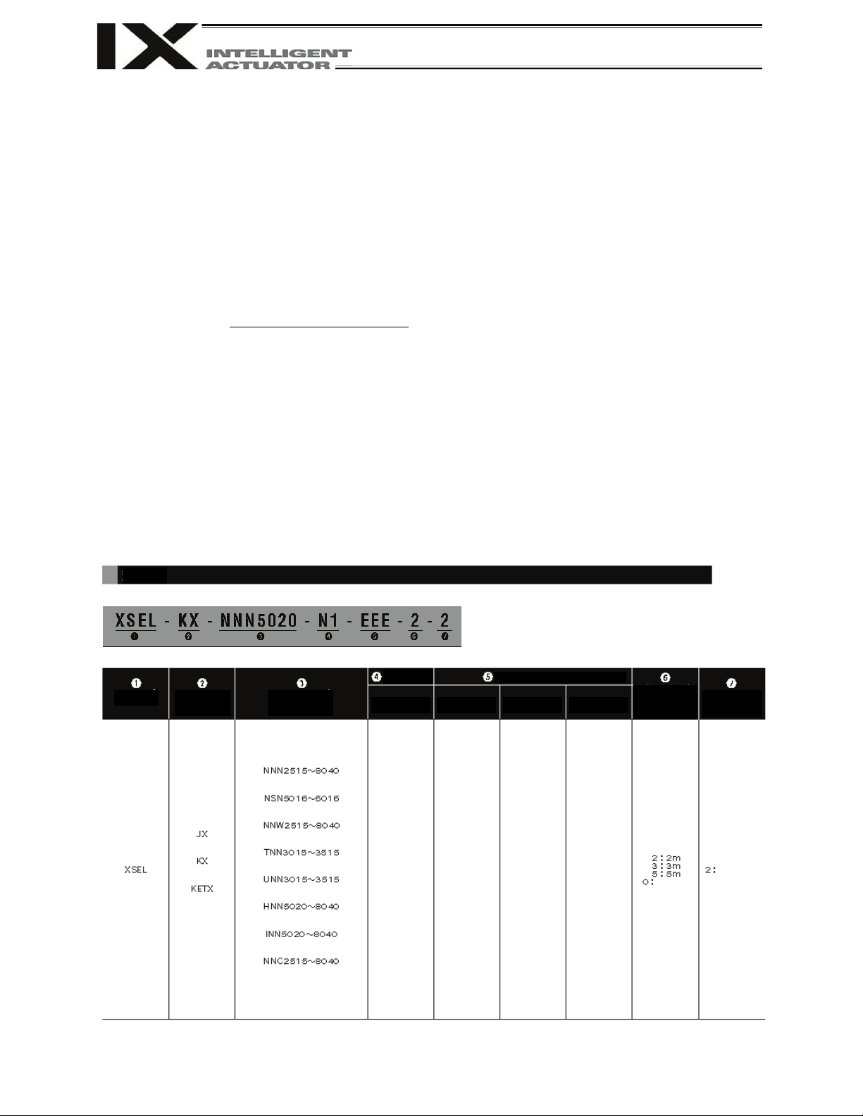
Example of model designation
Model table
type
(Dustproof/splash-proof type)
(General-
purpose type)
(General-
CE-compliant
type)
(Wall mount inverse type)
(Ceiling mount inverse type)
type
(High-speed type)
(Wall mount type)
(Ceiling mount type)
(Cleanroom type)
N1
[32 inputs/16 outputs
NPN board]
N3 (Note 3)
[48 inputs/48 outputs
NPN board]
P1
[32 inputs/16 outputs
PNP board]
P3 (Note 3)
[48 inputs/48 outputs
PNP board]
DV
[DeviceNet
256/256 board]
CC
[CC-Link
256/256 board]
PR
[ProfiBus
256/256 board]
ET
[Ethernet
Data communication
board]
E
(Not used)
C (Note 4)
[CC-Link
16/16 board]
N1
[Expanded I/O
NPN32/16]
N2
[Expanded I/O
NPN16/32]
N3 (Note 4)
[Multi-point I/O
NPN48/48]
P1
[Expanded I/O
PNP32/16]
P2
[Expanded I/O
PNP16/32]
P3 (Note 4)
[Multi-point I/O
PNP48/48]
SA (Note 4)
[Expanded SIO
Type A]
SB (Note 4)
[Expanded SIO
Type B]
SC (Note 4)
[Expanded SIO
Type C ]
length
(Note 2)
voltage
200-V
specification
Page 18

2
Caution
Part 1 Installation
Part 1 Installation
Chapter 1 Safety Precautions
This controller has been designed for use exclusively with IAI’s IX-Series Horizontal Articulated Robot,
and is able to provide integrated control over the entire system including peripherals. In other words , the
X-SEL Controller has the ability to control systems of all sizes ranging from a small system to a large
factory automation system. In general, however, the occurrence rate of accidents due to wrong operation
or carelessness will rise as the system becomes larger and more complex. Please give due consideration
to safety measures.
Strict observance of the following items is requested to prevent unforeseen danger. Also read the
appendix entitled, “Safety Rules and Others.”
1. Do not handle this product in manners not specified in this manual. If you have any question regarding
the content of this manual, please contact IAI.
2. Always use the specified, genuine IAI cables for wiring between the controller and the actuator.
3. Do not enter the operation area of the machine while the machine is operating or ready to operate (the
controller power is on). If the machine is used in a place accessible to other people, provide an
appropriate safety measure such as enclosing the machine with a cage.
4. When assembling/adjusting or maintaining/inspecting the machine, always turn off the controller power
at the source beforehand. The operator should display in a conspicuous place a plate or other sign
saying that operation is in progress and that the power should not be turned on. The operator should
keep the entire power cable beside him or her to prevent another person from inadvertently plugging in
the cable.
5. When two or more operators are to work together, set call-out signals to ensure safety of all personnel
during the work. In particular, a person turning on/off the power or moving an axis—either via a motor
or manually—must always say what he or she is going to do out loud and confirm the responses from
the others first before actually performing the operation.
Page 19

3
Part 1 Installation
Chapter 2 Warranty Period and Scope of Warranty
The X-SEL Controller you have purchased passed our strict outgoing inspection. This unit is covered by
the following warranty:
1. Warranty Period
The warranty period shall be either of the following periods, whichever ends first:
• 18 months after shipment from our factory
• 12 months after delivery to a specified location
2. Scope of Warranty
Should the product fail during the above period under a proper use condition due to a fault on the part
of the manufacturer, IAI will repair the defect free of charge. However, the following cases are
excluded from the scope of warranty:
• Discoloration of paint or other normal aging
• Wear of consumable parts due to use
• Subjective imperfection, such as noise not affecting mechanical function
• Defect caused by inappropriate handling or use by the user
• Defect caused by inappropriate or erroneous maintenance/inspection
• Defect caused by use of a part other than IAI’s genuine part
• Defect caused by unauthorized modification, etc., not approved by IAI or its agent
• Defect due to an act of God, accident, fire, etc.
The warranty covers only the product as it is delivered. IAI shall not be liable for any loss arising in
connection with the delivered product. The user must bring the defective product to our factory to
receive a warranty repair.
3. Scope of Service
The price of the delivered product does not include costs incurred in association with program
generation, dispatch of technician, etc. Therefore, a separate fee will be chargeable in the following
cases even during the warranty period:
• Guidance on installation/adjustment and witnessing of test operation
• Maintenance/inspection
• Technical guidance and trai nin g on operation, wiring method, etc.
• Technical guidance and training regarding programs, such as program generation
• Other services and operations where IAI finds a need to charge a separate fee
Page 20

4
24-VDC fan x 5 (compact type)
24-VDC fan x 6 (general-purpose type)
Part 1 Installation
Chapter 3 Installation Environment and Noise Measures
1. Installation Environment
(1) When installing and wiring the controller, do not block the ventilation holes provided for cooling.
(Insufficient ventilation will not only prevent the product from functioning fully, but it may also result in
failure.)
(2) Prevent foreign matter from entering the controller through the ventilation holes. Since the controller
is not designed as dustproof or waterproof (oilproof), avoid using it in a dusty place or place subject
to oil mist or splashed cutting fluid.
(3) Do not expose the controller to direct sunlight or radiant heat from a high heat source such as a heat-
treating furnace.
(4) Use the controller in a non-condensing environment free from corrosive or inflammable gases.
(5) Use the controller in an environm ent where it will not receive external vibration or impact.
(6) Prevent electrical noise from entering the controller or its cables.
Environmental Condition of Controller
Item Specification
Surrounding air temperature range
Forced air-cooling
Surrounding humidity range 30% ~ 85%
Storage temperature range
Dust protection structure IP10
Power-sour c e volta ge 100 to 115/200 to 230 VAC, single-phase
Operating power-source voltage
Rated operating power-source frequency 50 Hz/60 Hz
0°C ~ 40°C
-10°C ~ 65°C
±10%
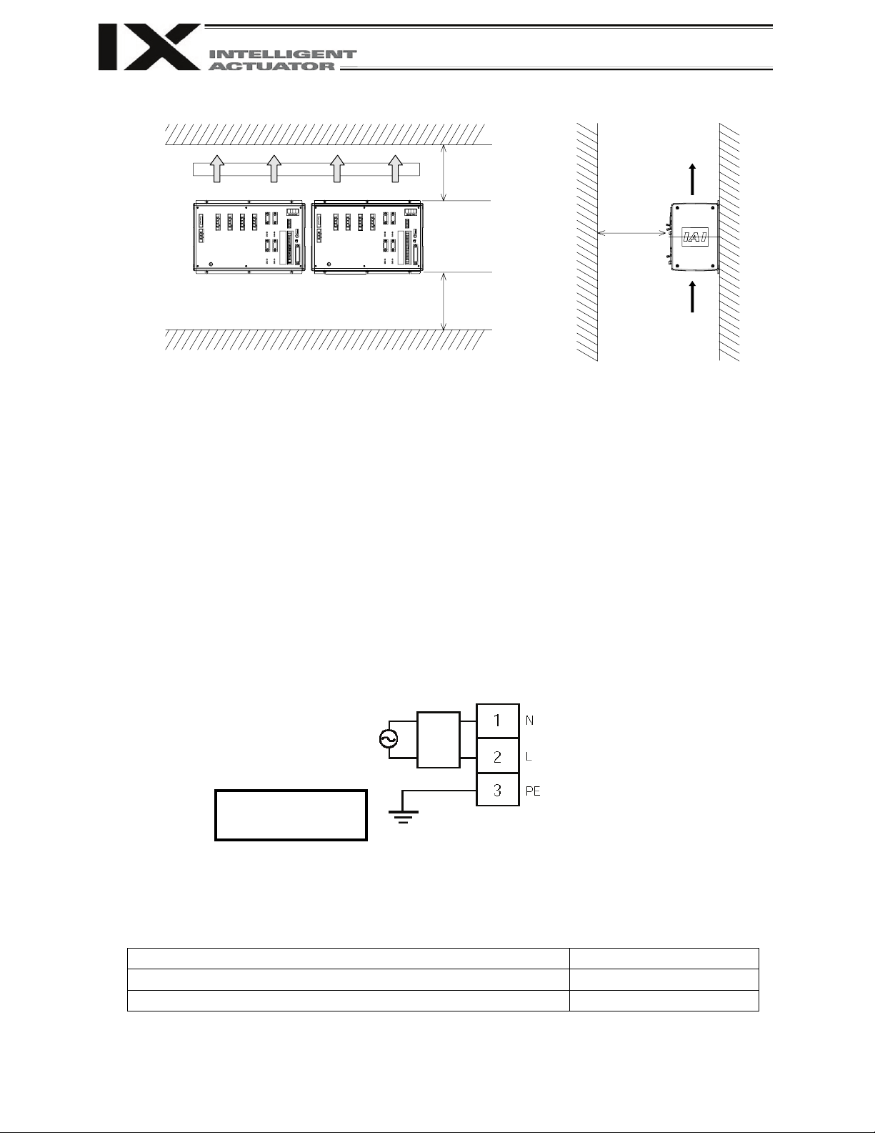
2. Heat Radiation and Installation
Design the control panel size, controller layout and cooling method so that the ambient temperature
around the controller will be kept at or below 40°C.
Install the controller vertically on a wall, as illustrated below. The controller will be cooled by forced
ventilation (exhaust air will be discharged from the top). Be sure to install the controller in the
aforementioned direction a nd pro vide a m inimum clearance of 150 mm above and 150 mm below the
controller.
If multiple controllers are to be installed side by side, providing additional suction fans on top of the
controllers will help maintain a uniform ambient temperature.
Provide a minimum clearance of 150 mm between the front side of the controller and a wall
(enclosure).
Page 21
5
POWERRBM4 M3 M2 M1
PG1
TP
PG2 PG4
I/02 I/01
PG3
CODE
POWERRBM4 M3 M2 M1
PG1
TP
PG2 PG4
I/02 I/01
PG3
CODE
Robot specification
Model
Arm length 700/800 specification, high-speed specification
MXB-1220-33
Other types
MXB-1210-33
Airflow direct io n
Airflow
150 mm min.
150 mm min.
150 mm
200-VAC power source
Class D grounding
Noise
Part 1 Installation
Fan
min.
If multiple controllers are to be connected on top of one another, prevent the controller above from
taking in the exhaust air from the controller below.
3. Power Source
Provide a single-phase power source of 200 to 230 VAC.
4. Noise Measures and Grounding
(1) Wiring and power source
PE on the power terminal block is used for protective grounding. Provide Class D grounding from this
terminal.
Use a grounding cable with a wire size of 1.0 mm
than the AC power cable.
Install a noise filter in the AC line to prevent the noise generating in the controller from traveling
through the power line to enter other unit.
(protective grounding)
Install the noise filter near the power connector on the X-SEL controller side.
Use of a noise filter by Densei-Lambda is recommended. The applicable noise filter model varies
depending on the robot specification, as shown below.
Recommended noise filter models (by Densei-Lambda)
2
(#AWG17) or more, which should not be smaller
filter
Page 22

6
AC power source
Class D grounding
Metal enclosure
Surge absorber
ACIN
N
X-SEL
Other
X-SEL
Other
Do not use this method.
Part 1 Installation
[2] Notes on wiring method
Use twisted cables for the AC power cable and 24-VDC external power cable. Wire the controller
cables separately from lines creating a strong electric field such as power circuit lines (by not
bundling them together or placing in the same cable duct).
If you wish to extend the motor cable or encoder cable beyond the length of each supplied cable,
please contact IAI.
(2) Noise-eliminat ion grou ndi n g
L
PE
Connect the FG terminal
with the metal enclosure
using a cable of a
maximum allowable size
over the shortest distance.
Provide dedicated FG or PE grounding.
equipment
equipment
controller
controller
(3) Noise sources and noise elimination
There are many noise sources, but solenoid valves, magnet switches and relays are of particular
concern when building a system. Noise from these parts can be eliminated using the measures
specified below:
[1] AC solenoid valve, magnet switch, relay
Measure --- Install a surg e absor ber in parallel with the coil.
← Point
Wire from each coil over the shortest distance.
Installing a surge killer on the terminal block,
etc., will be less effective because of a longer
distance from the coil.
Page 23
7
Diode
Controller
OUT
CR
+24 V
0 V
100 VAC
CR
0 V
Part 1 Installation
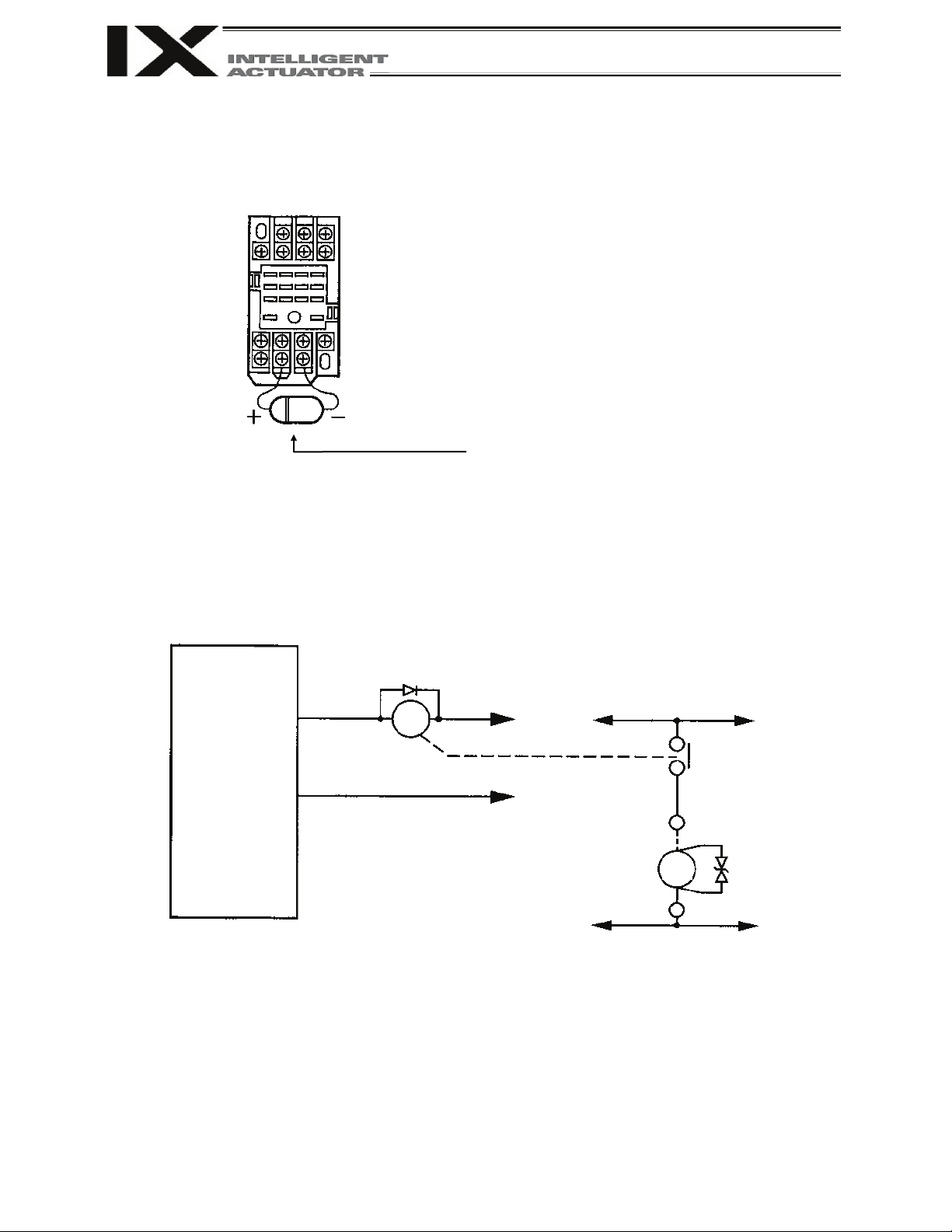
[2] DC solenoid valve, magnet switch, relay
Measure --- Install a diode in parallel with the coil. Determine the diode capacity in accordance with
the load capacity.
In a DC circuit, connecting a diode in reversed polarity will
damage the diode, internal parts of the controller and DC
power supply. Exercise due caution.
The above noise elimination measures are particularly important when a 24-VDC relay is driven
directly by a controller output and there is also a 100-VAC solenoid valve, etc.
Reference Circuit Diagram
COM
SOL
Surge absorber
Solenoid valve
Page 24
8
External regenerative unit
Motor connector
Encoder
System I/O
I/O24V power
Panel window (Refer to
FG terminal
Fuse holder
AC input
When this LED is lit in red, a system clock error is present.
gency stop is actuated or CPU hardware error or
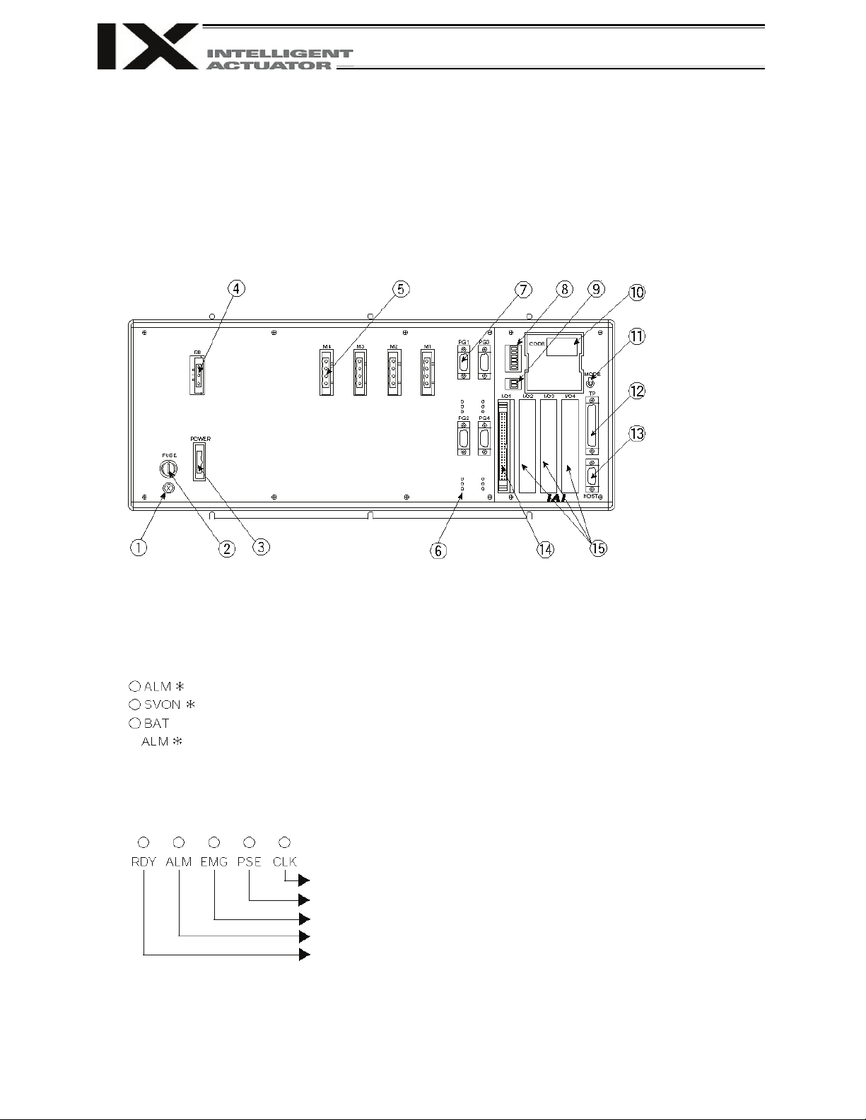
Chapter 4 Name and Function of Each Part
1. Front View of Controller
KX type (general-purpose type)
Applicable to robots of all strokes
Alarm and Other LED Indicators
[6] Driver status LEDs
[10] Panel window
4-digit, 7-segment LEDs: Refer to 2, “Explanation of Codes Displayed on the Panel Window.”
The following five LEDs are provided.
connector
connector
: When this LED is lit in orange, the driver is detecting an error.
: When this LED is lit in green, the servo is on and the motor is being driven.
: When this LED is lit in orange, the absolute-encoder b ac k up batter y voltage is lo w.
When this LED is lit in red, a power-system hardware error is present.
When this LED is lit in red, an emer
power-system hardware error is present.
When this LED is lit in red, a CPU alarm (system-down level error) or CPU
hardware error is present.
When this LED is lit in green, the CPU is ready (program operation is enabled).
Driver stat us LEDs
(Refer to the
explanation below.)
connector
Standard I/O
connector
connector
Part 1 Installation
connector
Expansion I/O
connectors
the explanation below.)
Mode switch
Teaching connector
PC connector
Page 25

9
External regenerative
Motor connector
Encoder
AC input
Driver stat us LEDs
Standard I/O
Expansion I/O
Panel window (Refer to
When this LED is lit in red, an emergency stop is actuated or CPU hardware error or
JX type (compact type)
Applicable to robots of 250/350 strokes
connector
the explanation below.)
connector
unit connector
System I/O connector
System-operation setting switches
Boot-target setting switch
Mode switch
Teaching connector
FG terminal
(Refer to the
explanation below.)
connectors
connector
Alarm and Other LED Indicators
[6] Driver status LEDs
: When this LED is lit in orange, the driver is detecting an error.
: When this LED is lit in green, the servo is on and the motor is being driven.
: When this LED is lit in orange, the absolute-encoder b ac k up batter y voltage is lo w.
[10] Panel window
4-digit, 7-segment LEDs: Refer to 2, “Explanation of Codes Displayed on the Panel Window.”
The following five LEDs are provided.
When this LED is lit in red, a system clock err or is pres ent.
When this LED is lit in red, a power-system hardware error is present.
power-system hardware error is present.
When this LED is lit in red, a CPU alarm (system-down level error) or CPU
hardware error is present.
When this LED is lit in green, the CPU is ready (program operation is enabled).
Part 1 Installation
Page 26

10
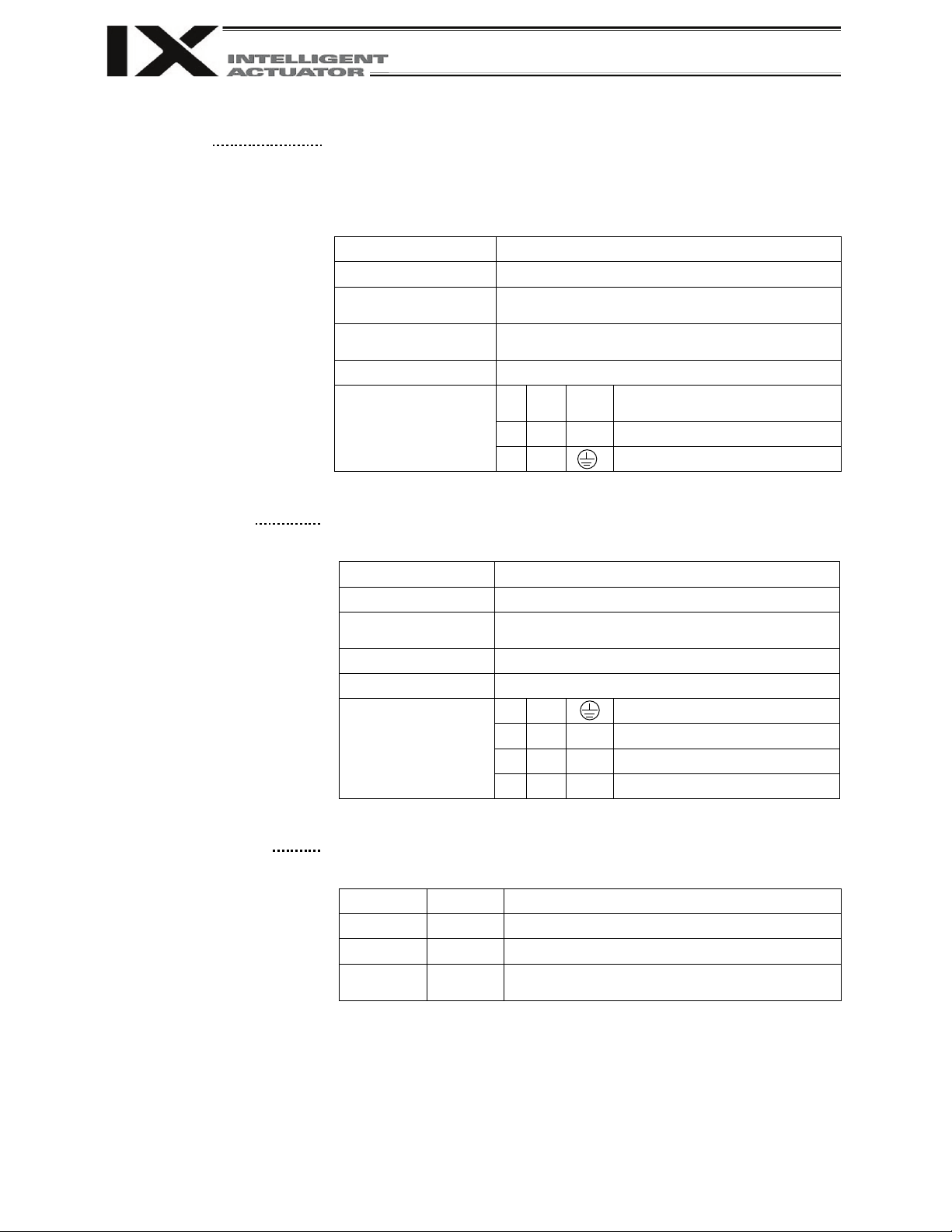
[1] FG terminal
This terminal is used to ground FG on the enclosure. With a general-
Be sure to ground the FG terminal.
[2] Fuse holder (general-
This half-cut fuse holder is used to protect overcurrent in the AC input
and uses a slow-blow fuse specified by IAI.
Melting
characteristics
[3] AC input connector
200-VAC, single-phase input connector.
3-pin, 2-piece connector
Terminal
*
Part 1 Installation
purpose type only)
purpose type, the enclosure is connected to PE in the AC input part inside
the controller.
With a compact type, FG and PE are not connected inside the controller.
FG Terminal Specifications
Item Overview
M4 3-point SEMS screw, 5 mm
Cable size 2.0 ~ 5.5 mm2
Grounding method Class D grounding
part. It prevents inflow of abnormal current generated by ground fault, etc.,
Overview of Fuse Holder Specifications
Item Description
Holder F-22001-A1 by Sato Parts
Fuse type TWO 250V20A by Fuji Terminal
Slow-blow
* With a compact type, the fuse holder is mounted on the board. Type:
FGMT5 AC250V10A by Fuji Terminal
AC Power Connector Specifications
Item Overview
Connector name POWER
Connector GMSTB2.5/3-STF-7.62 by Phoenix Contact
Supported cable size 1.25 ~ 2.5 mm2 (AWG12 ~ 16)
Connected to AC power source
assignments
1 In N AC power input, N side
2 In L AC power input, L side
3
PE (Protective grounding line)
Page 27
11
[4] External regenerative unit
This connector is used to connect a regenerative resistance unit that may
will be determined by the specific application such as axis configuration.
3-pin, 2-piece connector
Cable size
1.0 mm2 (AWG17 or equivalent), included in the
external regenerative box
(Motor-driving DC voltage)
[5] Motor connector
This connector is used to drive the motor inside the actuator.
Connector
GIC2.5/4-STF-7.62 by Phoenix Contact
4-pin, 2-piece connector
Terminal
the motor drive. The following three LEDs are provided.
The voltage of the absolute-data backup
battery is low.
Part 1 Installation
connector
be required when the controller is used in a high-speed/high-load
environment, etc., and the built-in regenerative resistance capacity is not
sufficient. Whether or not an external regenerative resistance is necessary
Overview of Fuse Holder Specifications
Item Overview
Connector name RB
Connector GIC2.5/3-STF-7.62 by Phoenix Contact
Connected to External regenerative box
Terminal
assignments
1 Out RB+
Regenerative resistance +
2 In RB– Regenerative resistance –
Overview of Motor Connector Specifications
Item Description
Connector name M
Cable Dedicated motor cable
Connected to Actuator
assignments
1
2 Out U Motor-driving phase U
PE (Protective grounding line)
3 Out V Motor-driving phase V
4 Out W Motor-driving phase W
[6] Driver status LEDs These LEDs monitor the operating status of the driver CPU that controls
Name Color Meaning when lit
ALM Orange The driver is detecting an error.
SVON Green The servo is on and the motor is being driven.
BAT ALM Orange
Page 28

12
[7] Encoder connector
This 15-pin, D-sub connector is used to connect the actuator’s encoder.
Connector name
PG
Maximum
distance
10 m
Interface
standard
Conforming to RS422
Connected to
Actuator
(Built-in encoder unit inside the actuator)
Connection cable
Terminal
Pin
No.
Signal
name
(Phase U+)
Phase-A differential – input
(Phase U–)
(Phase V+)
Phase-B differential – input
(Phase V–)
(Phase W+)
Phase-Z differential – input
(Phase W–)
switching+)
magnetic-pole switching–)
Backup-battery power
supply
Part 1 Installation
Encoder Connector Specifications
Item Description
Connector High-density D-sub, 15-pin (fem ale)
connection
Dedicated PG cable
assignments
I/O
1 In A+
Phase-A differential + input
Description
2 In A–
3 In B+
Phase-B differential + in pu t
4 In B–
5 In Z+
Phase-Z differential + input
6 In Z–
Send/receive line+
7 IO SRD+
8 IO SRD–
(Pulse/magnetic-pole
Send/receive line– (Pulse/
9 Out BATT
10 Out BATTGND Battery ground
11 Out VCC Encoder power source
12 Out GND GND
13 Out BK–
14 Out BK+
Brake output
15 FG Not used
Page 29

13
[8] System I/O connector
This connector is used to connect an emergency-stop switch, ENABLE
contact, ready relay, etc.
connector
1
RDY OUT
2
RDY OUT
3
ENB IN
Safety-gate input
4
+24V OUT
+24-V power output for safety gate
5
EMG IN
Emergency-stop input
+24-V power output for emergency
stop
Supported cable size
0.75 ~ 1.25 mm2 (AWG16)
MC1.5/2-ST-3.5 by Phoenix Contact; 2-pin, 2-piece
connector
1
0V
I/O GND
2
24V IN
+24-V power input for I/Os
[10] Panel window
This window consists of a 4-digit, 7-segment LED display and five LED
Name
Status when the LED is lit
RDY
CPU ready (program can be run)
ALM
CPU alarm (system-down level error), CPU hardware error
power-system hardware error
PSE
Power-system hardware error
CLK
System clock error
[11] Mode switch
This alternate switch with lock is used to command a controller operation
(Refer to the types of manual operations explained on p.324.)
Part 1 Installation
[9] I/O24V power connector
(general-purpose type
only)
Connector
Terminal assignments
Pins 1 and 2 form a contact-A output that turns ON under the following condition:
• SYSRDY is output (software = PIO trigger program can be run) and hardware is
normal (emergency stop is not being actuated and hardware error is not being
detected).
Pins 3 and 4 form a contact-B safety-gate input. Operation is enabled when the
pins are shorted, while the drive source is cut off when they are open.
Pins 5 and 6 form a contact-B emergency-stop input. Operation is enabled when
the pins are shorted, while an emergency stop is actuated when they are open.
Current flowing to the emergency stop contacts:
KX type (general-purpose ty pe ) : 43 mA ± 10%
JX type (compact type): 30 mA ± 10%
The controller is shipped with pins 3 and 4, and 5 and 6, shorted by a cable,
respectively.
MC1.5/6-ST-3.5 by Phoenix Contact; 6-pin, 2-piece
Ready-status output contact
6 +24V OUT
This connector is used to externally supply I/O power to the insulated part
when DI and DOs are mounted in the I/O connectors explained in [14] and
[15] (2-pin, 2-piece connector by Phoenix Contact). 24 V must be supplied
externally.
Connector
Terminal assignments
With a compact type, power is supplied externally to pin Nos. 1 and 50 of
the I/O connector in [14].
lamps that indicate the status of the equipment.
For the information shown on the display, refer to 2, “Explanation of
Codes Displayed on the Panel Window” or the “Error Code Table.”
Meanings of Five LEDs
EMG
Emergency stop has been actuated, CPU hardware error,
mode. To operate the switch, pull it toward you and tilt.
Tilting the switch upward will select MANU (manual mode), while tilting it
downward will select AUTO (auto mode). Teaching can be performed only
in the MANU mode, but auto program start is not enabled in the MANU
mode.
Page 30

14
[12] Teaching connector
When an optional teaching pendant or PC is connected, this D-sub, 25-
Communication
method
RS232C-compliant, start-stop synchronous
method
Maximum
connection distance
Signal
name
Terminal
Power output
teaching pendant)
pin connector will be used to input program and position data in the
MANU mode.
Interface Specifications of Teaching Serial Interface
Item Description
Connector name TP
Connector DSUB-25 XM3B-2542-502L (Omron)
Baud rate 38.4 kbps max.; half-duplex communication
Interface standard RS232C
Connected to X-SEL teaching pendant
Interface Specifications of Teaching Serial Interface
Part 1 Installation
10 m (38.4 kbps)
Item No. Direction
1 FG Frame ground
assignments
2 Out TXD Transmitted data
3 In RXD Received data
4 Out RTS Request to send
5 In CTS Clear to send
6 Out DSR Equipment ready
7 SG Signal ground
8
9 In Connection prohibited
10 In Connection prohibited
11
12 Out EMGOUT Emergency stop
13 In EMGIN
14
15 Out Connection prohibited
16 Out Connection prohibited
17 Out Connection prohibited
18 Out VCC
Description
(5-V power source for
19 In ENBTBX Enable input
20 In DTR Terminal ready
21
22
23 Out EMGS Emergency-stop status
24
25 SG Signal ground
Page 31

15
[13] PC connector (general-
This D-sub, 9-pin connector is used to perform serial communication
Maximum
distance
10 m (38.4 kbps)
user only when the teaching connector (D-sub, 25-pin) [12] is not in use.
[14] Standard I/O connector
This connector consists of a 50-pin flat connector and comprises 32-
With a general-purpose type, power is supplied from the
pin Nos. 1 and 50.
inputs)
16 points (including general-purpose and dedicated
outputs)
Part 1 Installation
purpose type only)
(RS232C) with the host equipment when AUTO is selected as the
operation mode.
* [12] and [13] cannot be used sim ultan eously.
RS232 Host Connector Specifications
This connector is used to establish a serial connection with a PC or PLC to enable
controller control.
Item Description
Connector name HOST
Connector D-sub, 9-pin (DTE); XM2C-0942-502L by Omron
connection
Interface standard RS232C
Connected to AT-compatible PC, etc. (half-duplex communication)
Connection cable Dedicated cable
Terminal
assignments
A dedicated cable must be used if an AT-compatible PC is to be
connected.
The PC connector (D-sub, 9-pin) [13] will become available for use by the
Pin No. I/O Signal name Description
1 NC
2 In RD Received data (RXD)
3 Out SD Transmitted data (TXD)
4 In DR Data set ready (DSR)
5 In SG Signal ground
6 Out ER Equipment ready (DTR)
7 Out RS Request to send (RTS)
8 In CS Clear to send (CTS)
9 NC Not used
The PC connector (D-sub, 9-pin) [13] and teaching connector (D-sub,
25-pin) [12] cannot be used simultaneously. Setting the mode switch
[11] to MANU will select the teaching connector [12], while setting it to
AUTO will select the PC connector [13].
input/16-output DIOs.
Overview of Standard I/O Interface Specifications
Item Description
Connector name I/O
Connector Flat connector, 50-pin
Power supply
Input
Output
Connected to External PLC, sensor, etc.
I/O24V power connector [9].
With a compact type, power is supplied from connector
32 points (including general-purpose and dedicated
Page 32

16
I/O Interface List
1
-
2
000
3
001
5
003
6
004
7
005
8
006
9
007
12
010
13
011
14
012
15
013
16
014
19
017
20
018
21
019
22
020
23
021
25
023
26
024
27
025
28
026
29
027
32
030
33
031
34
300
35
301
36
302
39
305
40
306
41
307
42
308
43
309
46
312
47
313
System-memory backup battery voltage-low
warning output
49
315
50
-
Part 1 Installation
These functions are based on
the factory settings. The
functions assigned to port
Nos. 000 to 014, 300 to 308,
313 and 314 can be changed
using the applicable I/O
parameters.
(Refer to Nos. 30 to 54, 59
and 60 in 1, “I/O Parameters”
of Appendix, “List of
Parameters.”)
Pin No. Category Port No. Function Cable color
General-purpose: NC, Compact: +24-V input Brown-1
Program start Red-1
General-purpose input Orange-1
4 002
10 008
11 009
Input
17 015
18 016
24 022
30 028
31 029
37 303
38 304
Output
44 310
45 311
48 314
General-purpose input Yellow-1
General-purpose input Green-1
General-purpose input Blue-1
General-purpose input Purple-1
General-purpose input Gray-1
Program specification (PRG No. 1) White-1
Program specification (PRG No. 2) Black-1
Program specification (PRG No. 4) Brown-2
Program specification (PRG No. 8) Red-2
Program specification (PRG No. 10) Orange-2
Program specification (PRG No. 20) Yellow-2
Program specification (PRG No. 40) Green-2
General-purpose input Blue-2
General-purpose input
General-purpose input
General-purpose input White-2
General-purpose input Black-2
General-purpose input Brown-3
General-purpose input Red-3
General-purpose input Orange-3
General-purpose input
General-purpose input Green-3
General-purpose input Blue-3
General-purpose input Purple-3
General-purpose input Gray-3
General-purpose input White-3
General-purpose input
General-purpose input
General-purpose input Red-4
General-purpose input Orange-4
Alarm output Yellow-4
Ready output Green-4
Emergency-stop output Blue-4
General-purpose output
General-purpose output
General-purpose output White-4
General-purpose output Black-4
General-purpose output Brown-5
General-purpose output Red-5
General-purpose output Orange-5
General-purpose output
General-purpose output
General-purpose output Blue-5
Absolute-encoder backup battery voltage-low
warning output
General-purpose output White-5
General-purpose: NC, Compact: 0 V Black-5
Purple-2
Gray-2
Yellow-3
Black-3
Brown-4
Purple-4
Gray-4
Yellow-5
Green-5
Purple-5
Gray-5
Page 33

17
[15] Expansion I/O connectors
These connectors are used to install I/O expansion boards.
[16] System-operation setting
These switches are used to set the system operation mode. Normally
set to “1.”
Part 1 Installation
I/O expansion boards are optional with a general-purpose type.
With compact types, on ly one expansion board can be installed.
Note) The connector pins are similar to those of the standard I/O
connector.
24 VDC must be input to pin Nos. 1 and 50.
switches (compact type only)
[17] Boot-target specification switch
(compact type only)
all switches should be set to OFF.
This switch is used to select the device that will be updated w he n the
system implements program update. Normally this switch should be
Page 34

18
Display
Priority (*1)
Description
AC power is cut off (including momentary power failure or drop in
power-source voltage).
Waiting for a drive-source cutoff reset input (except during the
update mode).
Operation is in pause (waiting for restart) (except during the update
mode).
Running a program (last started program); “No.” indicates program
number.
Part 1 Installation
2. Explanation of Codes Displayed on the Panel Window
2.1. Application
1
1 System-down level error
2 Writing data to the flash ROM.
3 Emergency stop is being actuated (except during the update mode).
4 Safety gate is open (except during the update mode).
5 Cold-start level error
5 Cold-start level error
5 Operation-cancellation level error
5 Operation-cancellation level error
6
6
7 All servo axes are interlocked (except during the update mode).
8 Message level error
8 Message level error
9 Core update mode
9 Core update is in progress.
9 Core update has completed.
9 Slave update mode
9 Slave update is in progress.
9 Slave update has completed.
9
9 Initialization sequence number
9 Debug mode
9 Ready status (auto mode)
9 Ready status (manual mode)
10 Deadman switch OFF (manual mode)
(*1) The priority increases as the number decreases.
Page 35

19
Display
Priority (*1)
Description
AC power is cut off (including momentary power failure or drop in
power-source voltage).
2.2. Core
1
1 Cold-start level error
1 Cold-start level error
1 Operation-cancellation level error
1 Operation-cancellation level error
2 Message level error
2 Message level error
2 Application update mode
2 Application update is in progress .
Part 1 Installation
2 Application update has completed.
2 Hardware test mode process
2 Clearing the application flash ROM.
2 Application flash ROM has been cleared.
2 Jump to the application
2 Core flash-ROM check process
2 Application flash-ROM check process
2 SDRAM check process
(*1) The priority increases as the number decreases.
Page 36

20
Total output when maximum
number of axes are connected
Operating power-sourc e vo ltag e
range
terminals and between the external terminals (together) and case)
Surrounding air temperature
range
For backup of absolute data: AB-3 by I AI
For backup of system memory: CR2032
Motor overcurrent, overload, motor-driver temperature check, overload
error
Teaching pendant, PC software, absolute-data backup battery unit, I/O
installed)
Part 1 Installation
Chapter 5 Specifications
1. Controller Specifications
1.1 JX Type (Compact Type) (for actuators of strokes from 250 to 350)
Type JX Type (Compact Type)
450 W
Power-sour c e volta ge Single-phase, 200 to 230 V
±10%
Power-source frequency 50 Hz/60 Hz
Insulation resistance
Withstand voltage 1500 VAC for 1 minute (Note)
Surrounding humidity range 30% to 85%
Storage temperature range
Axis control method AC full digital servo
Position detection methods Rotation data backup absolute encoder
10 MΩ min. (measured at 500 VDC between the power terminal and I/O
0°C to 40°C
-10°C to 65°C
Batteries
Speed setting 1 mm/sec to 2000 mm/sec
Acceleration/deceleration setting 0.01 G to 1 G
Programming language Super SEL language
Program steps 6000 steps (total)
Number of positions 3000 positions (total)
Number of programs 64 programs
Multi-tasking 16 programs
Storage device Flash ROM + SRAM battery backup
Data input methods Teaching pendant or PC software
Standard inputs 32 points (total of dedicated inputs + general-purpose inp uts)
Standard outputs 16 points (total of dedicated outputs + general-purpose outputs)
Expanded inputs/outputs Only one board can be installed.
Serial communication For connection of teaching pendant or PC
Other inputs/output Emergency-stop input, safety-gate input, system ready output
Protective functions
check, encoder-open detection, soft limit over, system error, battery
Drive-source cutoff method Semiconductor
Regenerative resistance
Built-in (1 kΩ, 20 W); external regenerative resistance supported
Accessory I/O flat cable
Optional parts and components
Note: The withstand voltage of the actuator motor is 1000 V for 1 minute.
When performing a withstand voltage test with the controller and actuator connected, make sure the test voltage and
duration will not exceed 1000 V and 1 minute, respectively.
shield cable, I/O expansion board (only one expansion board can be
Page 37

21
Total output when maximum
number of axes are connected
Operating power-sourc e vo ltag e
range
terminals and between the external terminals (together) and case)
range
For backup of absolute data: AB-3 by I AI
Motor overcurrent, overload, motor-driver temperature check, overload
error
Teaching pendant, PC software, absolute-data backup battery unit, I/O
shield cable, I/O expansion board
Part 1 Installation
1.2 KX Type (General-Purpose Type) (for actuators of strokes from 250 to 800)
Type KX Type (General-Purpose Type)
1750 W
Power-sour c e volta ge Single-phase, 200 to 230 V
±10%
Power-source frequency 50 Hz/60 Hz
Insulation resistance
Withstand voltage 1500 VAC for 1 minute (Note)
Surrounding air temperature
Surrounding humidity range 30% to 85%
Storage temperature range
Axis control method AC full digital servo
Position detection methods Rotation data backup absolute encoder
10 MΩ min. (measured at 500 VDC between the power terminal and I/O
0°C to 40°C
-10°C to 65°C
Batteries
For backup of system memory: CR2032
Speed setting 1 mm/sec to 2000 mm/sec
Acceleration/deceleration setting 0.01 G to 1 G
Programming language Super SEL language
Program steps 6000 steps (total)
Number of positions 3000 positions (total)
Number of programs 64 programs
Multi-tasking 16 programs
Storage device Flash ROM + SRAM battery backup
Data input methods Teaching pendant or PC software
Standard inputs 32 points (total of dedicated inputs + general-purpose inp uts)
Standard outputs 16 points (total of dedicated outputs + general-purpose outputs)
Expanded inputs/outputs 48 points per unit (a maximum of 3 units can be added)
Serial communication For connection of teaching pendant or PC
Other inputs/output Emergency-stop input, safety-gate input, system ready output
Protective functions
check, encoder-open detection, soft limit over, system error, battery
Drive-source cutoff method Relay
Regenerative resistance
Built-in (220 kΩ, 80 W); external regenerative resistance supported
Accessory I/O flat cable
Optional parts and components
Note: The withstand voltage of the actuator motor is 1000 V for 1 minute.
When performing a withstand voltage test with the controller and actuator connected, make sure the test voltage and
duration will not exceed 1000 V and 1 minute, respectively.
Page 38

22
Item
Specification
Input voltage
24 VDC ±10%
Input current
7 mA per circuit
ON voltage --- 16.0 VDC min.
OFF voltage --- 5.0 VDC max.
Insulation method
Photocoupler insulation
[4] Sequencer contact output (minimum load of approx. 5 VDC/1 mA)
*
General purpose
Compact
I/O24V connector
24V IN
Caution
Internal circuit
Input terminal
OFF duration
+
-
2. External I/O Specifications
2.1. NPN Specification
(1) Input part
External Input Specifications (NPN Specification)
ON/OFF voltage
[1] No-voltage contact (minimum load of approx. 5 VDC/1 mA)
External devices
[2] Photoelectric/proximity sensor (NPN type)
[3] Sequencer transistor output (open-collector type)
[Input circuit]
560 Ω
3.3 KΩ
Part 1 Installation
P24*
External power supply
24 VDC +10%
P24
If a non-contact circuit is connected externally, malfunction may result from leakage
current. Use a circuit in which leakage current in a switch-off state does not exceed 1 mA.
X-SEL controller’s input signal
At the default settings, the system recognizes the ON/OFF durations of input signals if they
are approx. 4 msec or longer. The ON/OFF duration settings can also be changed using I/O
parameter No. 20 (input filtering frequency).
ON duration
I/O interface pin No. 1
Page 39

23
Item
Specification
Load voltage
24 VDC
Maximum load current
100 mA per point, 400 mA per 8 ports Note)
Leakage current
0.1 mA max. per point
Insulation method
Photocoupler insulation
[1] Miniature relay
[2] Sequencer input unit
*
General purpose
Compact
24V IN
I/O24V connector
0V
Caution
Internal circuit
N*
P24*
+ - Surge absorber
Load
External power supply
(2) Output part
Part 1 Installation
External Output Specifications (NPN Specification)
TD62084 (or equivalent)
External devices
Note) 400 mA is the maximum total load current of every eight ports from output port No. 300. (The
maximum total load current of output port No. 300 + n to No. 300 + n + 7 is 400 mA, where n is 0
or a multiple of 8.)
[Output circuit]
D
10 Ω
Output terminal
24 VDC ± 10%
P24
N
In the event that the load is short-circuited or current exceeding the maximum load
current is input, the overcurrent protection circuit will be actuated to cut off the circuit.
However, give due consideration to the circuit connection layout to prevent short-circuit
or overcurrent.
I/O24V connector
I/O interface pin No. 1
I/O interface pin No. 50
Page 40

24
Item
Specification
Input voltage
24 VDC ±10%
Input current
7 mA per circuit
ON voltage --- 8 VDC max.
OFF voltage --- 19 VDC min.
Insulation method
Photocoupler insulation
[1] No-voltage contact (minimum load of approx. 5 VDC/1 mA)
[4] Sequencer contact output (minimum load of approx. 5 VDC/1 mA)
*
General purpose
Compact
I/O24V connector
0V
Internal circuit
Input terminal
External power supply
N*
OFF duration
+
-
2.2. PNP Specification
(1) Input part
ON/OFF voltage
Part 1 Installation
External Input Specifications (PNP Specification)
External devices
[2] Photoelectric/proximity sensor (PNP type)
[3] Sequencer transistor output (open-collector type)
[Input circuit]
N
560 Ω
3.3 KΩ
I/O interface pin No. 50
24 VDC +10%
Caution
If a non-contact circuit is connected externally, malfunction may result from leakage
current. Use a circuit in which leakage current in a switch-off state does not exceed 1 mA.
X-SEL controller’s input signal
At the default settings, the system recognizes the ON/OFF durations of input signals if they
are approx. 4 msec or longer. The ON/OFF duration settings can also be changed using I/O
parameter No. 20 (input filtering frequency).
ON duration
Page 41

25
Item
Specification
Load voltage
24 VDC
Maximum load current
100 mA per point, 400 mA per 8 ports Note)
Leakage current
0.1 mA max. per point
Insulation method
Photocoupler insulation
[1] Miniature relay
[2] Sequencer input unit
*
General purpose
Compact
I/O24V connector
24V IN
0V
Caution
N
P24
Surge absorber
Output terminal
External power supply
+
-
(2) Output part
Part 1 Installation
External Output Specifications
TD62784 (or equivalent)
External devices
Note) 400 mA is the maximum total load current of every eight ports from output port No. 300. (The
maximum total load current of output port No. 300 + n to No. 300 + n + 7 is 400 mA, where n is 0
or a multiple of 8.)
[Output circuit]
Internal circuit
10 Ω
24 VDC +10%
P24
N
In the event that the load is short-circuited or a current exceeding the maximum load
current is input, the overcurrent protection circuit will be actuated to cut off the circuit.
However, give due consideration to the circuit connection layout to prevent short-circuit
or overcurrent.
I/O24V connector
I/O interface pin No. 1
I/O interface pin No. 50
Page 42

26
3. Power-Source Capacity and Heat Output of the Controller
The power-source capacity and heat output vary as follows, depending on the robot stroke.
Robot stroke length Power-source capacity Heat outp ut
700/800 3625 VA 133 W
500/600 1963 VA 99 W
250/350 1118 VA 81 W
Part 1 Installation
Page 43

27
POWER
RB
M4 M3 M2 M1
PG1
TP
PG2 PG4
I/02 I/01
PG3
CODE
5
180
4. External Dimensions
4.1 JX Type (Compact type)
35.9 112.5 112.5 35.9 3 - ∅ 5 125.3
(296.9)
Part 1 Installation
186
195
Page 44

28
RB
POWER
FUSE
M4 M3 M2 M1
PG1
PG2
PG3
PG4
I/O1 I/O2 I/O3 I/O4
CODE
HOST
TP
MODE
454.5
5
77.2 150 150 77.2 125.3
4.2 KX Type (General-purpose type)
3 - ∅ 5
Part 1 Installation
186
180
195
Page 45

29
Class D grounding
PG cable
U cable
Quick joint
24 VDC power
Tool, control
Chapter 6 System Setup
A connection example is given below:
1. Connection Method of Controller and Robot (KX T y pe)
AC power
source
(protective grounding)
M cable
PC software
(optional)
Standard cable length: 5 m
To air tube
(provided by user)
(cable for user wiring)
BK power cable
Teaching pendant
(optional)
supply for brake
(provided by
user)
Part 1 Installation
Output voltage: 24 VDC ± 10%
Capacity: 20 to 30 W
unit, etc.
(provided by
user)
Page 46

30
(1) Connect to the controller the motor cable and encoder cable from the actuator.
(2) Connect the teaching-pendant cable to the teaching connector. After the connection, set the mode
switch to MANU (by tilting the switch upward).
(If the mode switch is set to AUTO, the teaching pendant will not operate and RS-232 communication
will not establish after the power is turned on.)
(3) Connect the power cable to the controller.
(4) The panel window will display the code “rdy” to indicate that the preparation is complete.
If “ErG” is displayed, EMERGENCY STOP signal is being input. Reset the emergency stop.
This completes the preparation.
• The RDY terminals (Nos. 1 and 2) on the system I/O connector are relay-contact terminals shorted in
the ready mode.
• The ENB terminals (Nos. 3 and 4) on the system I/O connector are enable terminals. The controller
can operate when these terminals are shorted. The drive source will be cut off when the terminals are
open.
• The EMG terminals (Nos. 5 and 6) on the system I/O connector are emergency-stop switch connection
terminals. An emergency stop will be actuated when these terminals are open.
The controller is shipped with terminal Nos. 3 and 4, and 5 and 6, shorted, respectively.
Part 1 Installation
Page 47

31
Pin No.
Category
Port No.
Function
1
-
General-purpose: NC, Compact: + 24-V input
2
000
Program start
3
001
4
002
5
003
6
004
General-purpose input
7
005
General-purpose input
8
006
General-purpose input
9
007
Program specification (PRG No. 1)
10
008
11
009
12
010
Program specification (PRG No. 8)
13
011
Program specification (PRG No. 10)
14
012
Program specification (PRG No. 20)
15
013
Program specification (PRG No. 40)
16
014
17
015
19
017
General-purpose input
20
018
General-purpose input
21
019
General-purpose input
22
020
General-purpose input
23
021
24
022
25
023
General-purpose input
26
024
General-purpose input
27
025
General-purpose input
28
026
General-purpose input
29
027
General-purpose input
30
028
31
029
32
030
General-purpose input
33
031
General-purpose input
34
300
Alarm output
35
301
Ready output
36
302
37
303
39
305
General-purpose output
40
306
General-purpose output
41
307
General-purpose output
42
308
General-purpose output
43
309
44
310
45
311
General-purpose output
46
312
General-purpose output
47
313
System-memory backup battery voltage-low
warning output
48
314
Absolute-encoder backup battery voltage-low
warning output
49
315
General-purpose output
50
-
General-purpose: NC, Compact: 0 V
(Note)
(Note)
0 V
+24 V
2. I/O Connection Diagram
(1) NPN specification
General-purpose input
General-purpose input
General-purpose input
Program specification (PRG No. 2)
Program specification (PRG No. 4)
General-purpose input
Input
18 016
General-purpose input
General-purpose input
Part 1 Installation
Digital switch
38 304
Output
General-purpose input
General-purpose input
General-purpose input
General-purpose input
Emergency-stop output
General-purpose output
General-purpose output
General-purpose output
General-purpose output
With a general-purpose (K) type, pin Nos. 1 and 50 are not connected.
With a compact (J) type, +24 V is connected to pin No. 1, while 0 V is connected to pin No. 50.
Page 48

32
Pin No.
Category
Port No.
Function
1
-
General-purpose: NC, Compact: + 24-V input
2
000
Program start
3
001
4
002
5
003
General-purpose input
6
004
General-purpose input
7
005
General-purpose input
8
006
General-purpose input
9
007
10
008
11
009
12
010
Program specification (PRG No. 8)
13
011
Program specification (PRG No. 10)
14
012
Program specification (PRG No. 20)
15
013
Program specification (PRG No. 40)
16
014
17
015
18
016
General-purpose input
19
017
General-purpose input
20
018
General-purpose input
21
019
General-purpose input
22
020
General-purpose input
23
021
24
022
25
023
General-purpose input
26
024
General-purpose input
27
025
General-purpose input
28
026
General-purpose input
29
027
30
028
31
029
General-purpose input
32
030
General-purpose input
33
031
General-purpose input
34
300
Alarm output
35
301
Ready output
36
302
37
303
38
304
General-purpose output
39
305
General-purpose output
40
306
General-purpose output
41
307
General-purpose output
42
308
General-purpose output
43
309
44
310
45
311
General-purpose output
46
312
General-purpose output
47
313
System-memory backup battery voltage-low
warning output
48
314
Absolute-encoder backup battery voltage-low
warning output
49
315
General-purpose output
50
-
General-purpose: NC, Compact: 0 V
Digital switch
(2) PNP specification
Input
Part 1 Installation
General-purpose input
General-purpose input
Program specification (PRG No. 1)
Program specification (PRG No. 2)
Program specification (PRG No. 4)
General-purpose input
General-purpose input
Output
General-purpose input
General-purpose input
General-purpose input
General-purpose input
Emergency-stop output
General-purpose output
General-purpose output
General-purpose output
With a general-purpose (K) type, pin Nos. 1 and 50 are not connected.
With a compact (J) type, +24 V is connected to pin No. 1, while 0 V is connected to pin No. 50.
Page 49

33
Connector not attached
Socket (with strain relief): XG4M-5030-T (Omron)
Flat cable (50 cores)
2 1 50
49
3. I/O Flat Cable
No. Color No. Color No. Color No. Color No. Color
1 Brown-1 11 Brown-2 21 Brown-3 31 Brown-4 41 Brown-5
2 Red-1 12 Red-2 22 Red-3 32 Red-4 42 Red-5
3 Orange-1 13 Orange-2 23 Orange-3 33 Orange-4 43 Orange-5
4 Yellow-1 14 Yellow-2 24 Yellow-3 34 Yellow-4 44 Yellow-5
5 Green-1 15 Green-2 25 Green-3 35 Green-4 45 Green-5
6 Blue-1 16 Blue-2 26 Blue-3 36 Blue-4 46 Blue-5
7 Purple-1 17 Purple-2 27 Purple-3 37 Purple-4 47 Purple-5
8 Gray-1 18 Gray-2 28 Gray-3 38 Gray-4 48 Gray-5
9 White-1 19 White-2 29 White-3 39 White-4 49 White-5
10 Black-1 20 Black-2 30 Black-3 40 Black-4 50 Black-5
Part 1 Installation
Flat cable: KFX-50 (S) (Color) (Kaneko Cord)
Page 50

34
Part 1 Installation
Chapter 7 Maintenance
• Routine maintenance and inspection are necessary so that the system will operate properly at all
time. Be sure to turn off the power before performing maintenance or inspection.
• The standard inspection interval is six months to one year. If the environment warrants, however, the
interval should be shortened.
1. Inspection points
• Check to see if the supply voltage to the controller is inside the specified range.
• Inspect the ventilation holes in the controller and remove dirt, dust and other foreign attachments, if
any.
• Inspect the controller cables (controller → actuator) and check for any loose screws or cable
disconnection.
• Check the controller mounting screws, etc., for looseness.
• Inspect each cable (axis link cable, general-purpose I/O cable, system I/O cable, power cable) for
loose connection, disconnection, play, etc.
2. Spare consumable parts
Without spare part s, a failed controller cannot be repaired even when the problem is identifie d q uic kly.
We recommend that you keep the following consumable parts as spares:
Consumable parts
• Cables
• System-memory backup battery: CR2032 (Note 1) --- Battery life: Approx. 1 year *
• Absolute-date backup battery: AB-3 by IAI --- Battery life: Approx. 3 years *
(Absolute-data backup battery is installed on the robot.)
• Fuses
* The actual battery life will vary depending on the use condition.
(Note 1) CR2032 is a standardized product and can be used with products by any manufacture.
Memory backup
The X-SEL Controller saves program, position, coordinate system and parameter data to its flash
memory (when written to the flash memory). The data saved by the system-memory backup battery
are positions, coordinate system data, SEL global data and error lists. (Refer to Chapter 1, “How to
Save Data,” of Part 3.)
When the battery voltage drops, an applicable error code will be displayed on the panel window.
Error Codes Indicating Low Battery Voltage
System-memory backup battery A01 or A02
Absolute-data backup battery A03, A23 or D72
In the case of a low battery voltage of the absolute-data backup battery, the axis-driver status LED
will also illuminate.
Page 51

35
Part 1 Installation
3. Replacement Procedure of System-Memory Backup Battery (CR2032) for K Type (General-Purpose
Type)
Backing up the system memory
If “Other parameter No. 20, System-memory backup battery installation function type” is set to “2”
(installed), the following SRAM data in the X-SEL Controller will be backed up by the system-memory
backup battery on the panel board:
• Position data
• Coordinate system data
• SEL global data (flags, integer/real variables, string variables)
• Error lists
Therefore, the above SRAM data will be destroyed if the system-memory backup battery is removed
when “Other parameter No. 20, System-memory backup battery installation function type” is set to “2”
(installed). For this reason, always follow the procedure below when replacing the system-memory
backup battery:
[1] Turn on the controller power.
[2] Record (write down) the current setting of “Other parameter No. 20, System-memory backup
battery installation function type.” (This will be used when reverting the parameter to its original
setting following the replacement of system-memory backup battery.)
[3] If the PC software is installed in your PC, save the position data to a file using the PC software.
The data will be used as a backup in case the SRAM data saved to the flash ROM fails.
[4] Change “Other parameter No. 20, System-memory backup battery installation function type” to
“1” and transfer the setting to the controller, and then perform a flash ROM write. (The point data
will be saved to the flash ROM.)
* Confirm that the flash ROM writing process has completed.
[5] Perform a software reset (restart) to restart the controller. (The SEL global data and error lists
will be saved to the special area in the flash ROM.)
[6] When the controller has been restarted, turn off the power.
* Once the controller has been restarted, be sure to keep the power on until the initialization
sequence number is no longer displayed on the panel window (while “InXX” is displayed
following “8888”; XX indicates a number).
[7] Replace the system-memory backup battery. The battery is mounted on the panel board and
can be removed using two small screwdrivers or the like. When removing the current battery and
installing a new one, pay due attention to the following points (SRAM data will be destroyed if
steps 1 through 6 are not performed properly):
● Do not damage the board patterns.
● Do not short the circuits.
● Connect the battery in the correct polarities.
Page 52

36
Battery Replacement Procedure
1) Remove the 7-segment LED panel from the
controller. Slide the panel upward and pull it toward
you to remove.
2) As shown at lef t, remove the battery from the
holder using two screwdrivers, and then install a
new battery in the holder.
3) Install the panel in the original position.
[8] When the replacement of system-memory backup battery is complete, confirm that the battery is
installed securely and then turn on the controller power.
[9] Revert “Other parameter No. 20, System-memory backup battery installation function type” to
the value recorded in step 2, transfer the setting to the controller, and then perform a flash ROM
write.
* Confirm that the flash ROM writing process has completed.
[10] Perform a software reset (restart the controller).
[11] When the controller has been restarted, confirm that the SRAM data have been restored.
Part 1 Installation
Page 53

37
4. Replacement Procedure of System-Memory Backup Battery (CR2032) for J Type (Compact Type)
[Absolute specification]
In the case of a compact controller of absolute specification, an absolute reset must be performed
after replacing the system-memory backup battery. (Since all cables and absolute-data backup
battery are disconnected from the controller during the replacement procedure, the absolute data will
be destroyed.)
[Memory backup]
If “Other parameter No. 20, System-memory backup battery installation function type” is set to “2”
(installed), the following SRAM data in the X-SEL Controller will be backed up by the system-memory
backup battery on the main CPU board:
• Position data
• Coordinate system data
• SEL global data (flags, integer/real variables, string variables)
• Error lists
Therefore, the above SRAM data will be destroyed if the system-memory backup battery is removed
when “Other parameter No. 20, System-memory backup battery installation function type” is set to “2”
(installed). For this reason, always follow the procedure below when replacing the system-memory
backup battery:
[Replacement procedure for system-memory backup battery]
[1] Turn on the controller power.
[2] Record (write down) the current setting of “Other parameter No. 20, System-memory backup
battery installation function type.” (This will be used when reverting the parameter to its original
setting following the replacement of system-memory backup battery.)
[3] If the PC software is installed in your PC, save the position data to a file using the PC software.
The data will be used as a backup in case the SRAM data saved to the flash ROM fails.
[4] Change “Other parameter No. 20, System-memory backup battery installation function type” to
“1” and transfer the setting to the controller, and then perform a flash ROM write. (The point data
will be saved to the flash ROM.)
* Confirm that the flash ROM writing process has completed.
[5] Perform a software reset to restart the controller. (The SEL global data and error lists will be
saved to the special area in the flash ROM.)
[6] When the controller has been restarted, turn off the power.
* Once the controller has been restarted, be sure to keep the power on until the initialization
sequence number is no longer displayed on the panel window (while “InXX” is displayed
following “8888”; XX indicates a number).
[7] Replace the system-memory backup battery. When removing the current battery and installing a
new one, pay due attention to the following points (SRAM data will be destroyed if steps 1
through 6 are not performed properly):
• Do not damage the board patterns.
• Do not short the circuits.
• Connect the battery in the correct polarities.
Part 1 Installation
Page 54

38
Segment board
Main board
[Battery replacement method]
1) Disconnect all cables from the controller.
2) Remove the screws shown by arrows that
are mounting the front panel.
3) Remove the front panel.
4) Remove the screws mounting the segment
board.
Part 1 Installation
Page 55

39
Battery
Battery
5) As shown at left, use small screwdrivers to
remove the segment board.
6) Remove the screws mounting the main CPU
board.
7) As shown at left, use small screwdrivers to
remove the main CPU board. (The main CPU
board is sandwiched between the enclosure
guides.)
8) Replace the battery located in the position
shown by an arrow in the figure at left.
Part 1 Installation
Page 56

40
As shown at left, use small screwdrivers to
remove the battery from the holder and then
install a new battery in the holder.
[8] When the replacement of system-memory backup battery is complete, confirm that the battery is
installed securely. (Pay attention to the polarities of the battery.)
[9] Install the main CPU board, segment board and front panel in the reverse steps.
[10] Connect the controller and the actuator using the cables. Connect the power cable and turn on
the controller power.
[11] Revert “Other parameter No. 20, System-memory backup battery installation function type” to
the value recorded in step 2, transfer the setting to the controller, and then perform a flash ROM
write.
* Confirm that the flash ROM writing process has completed.
[12] Perform a software reset and restart the controller.
[13] When the controller has been restarted, confirm that the SRAM data have been restored.
Part 1 Installation
Page 57

41
Teaching pendant
Start
Start
PC software
X-SEL
Starting via
Start
Part 2 Operation
Part 2 Operation
Chapter 1 Operation
How to Start a Program
With the X-SEL Controller, the stored programs can be started (run) using four methods. Of these
methods, two are mainly used to debug programs or perform trial operations, while the remaining two are
used in general applications on site.
The former two methods are “starting from the teaching pendant” and “starting from the PC software.”
These methods provide simple means of checking the operation. For details on “starting from the teaching
pendant,” read the operation manual for the optional teaching pendant. For “starting from the PC
software,” read the applicable explanation in the manual supplied with the PC software.
The latter two methods are “starting automatically via parameter setting” and “starting via external signal
selection.” This chapter only explains the methods for “starting automatically via parameter setting” and
“starting via external signal selection.”
Controller
Starting
automatically via
parameter setting
external signal
selection
Page 58

42
Caution
Set an auto-start prog r am nu mb er
Reset the controller
Automatically starting the program
This parameter is set using the teaching pendant or PC software.
1. Starting a Program by Auto-Start via Parameter Setting
I/O parameter No. 33 (input function selection 003) = 1 (default factory setting)
Set the number of the program you wish to start
automatically in other parameter No. 1 (auto-start
program number).
Set the controller mode to AUTO.
Reconnect the power, and the controller will be reset.
Once the controller is reset in the above step, the
program of the set number will start automatically.
*
Part 2 Operation
[Note on starting a program by auto-start]
The automatic operation will begin immediately after the controller is reset, so the user may be surprised
by unexpected movements of the equipment, particularly those ca us ed b y a sudden activation of the servo
actuator. To ensure safety, always provide an interlocking function, such as allowing the program
execution to proceed only after receiving a confirmation signal at the beginning of the program.
If you wish to start multiple programs at the same time, write multiple “EXPG” commands at the beginning
of the main program to start the remaining programs. Provide safety measures for each program to be
started.
* When I/O parameter No. 33 is set to “2”
The program of the selected number will start automatically at the ON edge of input signal received by
input port No. 3.
The program will be terminated at the OFF edge.
Page 59

43
Select a desired program number externally and then input a start signal.
Power ON
READY signal ON
Program number
N
N N N Y Y
Y
N N Y
N
Program run
Emergency-stop
Controller
ALARM signal ON
Alarm output
External start input
Program number
Ready output
External device
Power ON
READY signal
Various I/O
Program number
Start signal ON
Emergency-stop
Emergency-stop
ALARM
Y
Y
2. Starting via External Signal Selection
(1) Flow chart
error?
Controller
confirmed?
Start signal
confirmed?
signal confirmed?
Servo OFF
input
Emergency-stop
input
confirmed?
Y
processing
specification
switch ON?
signal ON
ALARM signal
confirmed?
processing
Part 2 Operation
When the READY signal turns ON,
the RDY lamp (green) on the
controller front panel will illuminate.
Input a desired program number as
a BCD code from the external
device.
Input a start signal from the
external device.
When the program is run, the
number of the started program will
be shown in the CODE display
area of the controller front panel.
If an emergency-stop signal was
input from the external device or a
controller error occurred, the
controller will turn off the servo
power. (The RDY lamp will turn
off.)
Page 60

44
Duration after the program number is input until
Ready output
T1: Duration after the ready output turns ON, until
Set the program you want to start automatically
T1: Duration after the ready output turns ON, until
Ready output
T1: Duration after the ready output turns ON, until
(2) Timing chart
[1] Program start
Ready output
Program
number input
External start
input
Program 1 Program 2
[2] Program start by auto-start
* When I/O parameter No. 33 is set to “2”
Input by input
function 003
Auto program
start
[3] Software reset signal
* When I/O parameter No. 31 is set to “1”
Ready output
Input by input
function 001
Program
starting
[4] Servo ON signal
* When I/O parameter No. 32 is set to “1”
Input by input
function 002
Servo ON
[5] When the recovery action following an emergency stop or enable operation is set to “continued
operation”
* When other parameter No. 10 is set to “2”
Set I/O parameter No. 35 to “1” (Operation-pause reset signal)
Set I/O parameter No. 44 to “1” (Drive-source cutoff reset input)
Program
starting
Emergency
stop
Drive-source
cutoff reset
Pause reset
Part 2 Operation
T1: Duration after the ready output turns ON until
input of external start signal is permitted
T1 = 10 msec min .
T2:
input of external start signal is permitted
T2 = 50 msec min.
T3: Input duration of external start signal
T3 = 100 msec min.
input by the input function 003 is permitted
T1 = 10 msec min.
* Auto program start:
in other parameter No. 1, “Auto-start program
number.”
input by the input function 001 is permitte d
T1 = 10 msec min.
T2: Duration until the software reset signal
becomes functional
T2 = 1 sec min.
T3: Duration after the software reset signal is reset,
until the ready signal is output
input by the input function 002 is permitte d
T1 = 10 msec min.
T2: Interval after the servo turns off, until the servo
turns on again
T2 = 1.5 sec min.
T1: Duration after the emergency stop input is reset,
until the drive-source cutoff reset signal can be
input
T1 = 2 sec min.
T2: Duration over which the drive-source cutoff reset
signal is input
T2 = 10 msec min.
T3: Duration over which the pause reset signal is input
T3 = 10 msec min.
Page 61

45
Part 2 Operation
3. Drive-Source Recovery Request and Operation-Pause Reset Request
(1) Drive-source recovery request
1. How to request a drive-source recovery
A drive-source recovery request can be issued using one of the following methods:
• Set I/O parameter No. 44 to “1” (Input selection function 014 = Drive-source cutoff reset input),
then input the ON edge to input port No. 14.
• Select [Drive-Source Recovery Reques t (P
screen.
• Select Ctl (controller operation) and RPwr (drive-source recovery request) on the mode
selection screen of the teaching pendant.
2. Case where a drive-source request is required
A drive-source recovery request is required in the following case:
• A drive-source cutoff factor occurred when I/O parameter No. 44 was set to “1” → Rec ov er y after
the cutoff factor is removed.
(2) Operation-pause reset request
1. How to request an operation-pause reset
An operation-pause reset request can be issued using one of the following methods:
• Set I/O parameter No. 35 to “1” (Input selection function 005 = Operation-pause reset signal),
then input the ON edge to input port No. 5.
• Select [Operation-Pause Reset Request (L)] from the [Controller (C)] menu on the PC software
screen.
• Select Ctl (controller operation) and RAct (operation-pause reset request) on the mode
selection screen of the teaching pendant.
2. Cases where an operation-pause reset request is required
An operation-pause reset request is required in any of the following cases:
• The automatic operation was stopped using the deadman switch when other parameter No. 9
was set to “2” (Deadman-switch recovery type = Continued operation) (only during automatic
operation) → Recovery (reset of operation pause) after the stop is reset.
• An emergency stop was actuated during automatic operation when other parameter No. 10
was set to “2” (Emergency-stop recovery type = Contin ued oper a tio n) (on l y during automatic
operation) → Recovery (reset of operation pause) after the emergency stop is reset.
• The safety gate was opened during automatic operation when other parameter No. 11 was set
to “2” (Safety-gate open recovery type = Continued operation) (only during automatic
operation) → Recovery (reset of operation pause) after the safety gate is closed.
• An OFF-level input signal was received by input port No. 6 when I/O parameter No. 36 was set
to”1” (Input selection function 006 = Operation-pause signal) → Recovery (reset of operation
pause) after an ON-level input signal is received by input port No. 6.
* If the case in 2 of (1) and any of the cases in 2 of (2) are present at the same time, a drive-source
recovery request must be issued first, followed by an operation-pause reset request.
)] from the [Controller (C)] menu on the PC software
Page 62

46
Driver
Driver
Driver
Driver
Parameters
Parameters
Communication
Main
SEL language
Part 3 Controller Data Structure
Part 3 Controller Data Structure
The controller data consists of parameters as well as position data and application programs used to
implement SEL language.
X-SEL Controller Data Structure
1
2
The user must create position data and application programs. The parameters are predefined, but their
settings can be changed in accordanc e with the us er’s system.
Refer to Appendix, “List of Parameters,” for details on the parameters.
3
Parameters Parameters
4
Parameters
Position
data,
coordinate
system
data
Application
programs
Page 63

47
Data edited on the PC
Data will be retained while
Programs,
Slave car ds,
Positions,
Transfer
Transfer
Transfer
Transfer
Transfer
Temporary
Temporary
Write to flash memory
Read for reset
Transfer
Flash
EEPROM
Transfer
*Encoder
Battery
Battery
Write to flash
Read for reset
Read for reset
Part 3 Controller Data Structure
Chapter 1 How to Save Data
Since the IX-Series Controller uses flash memory, some data are saved by battery backup while others
are saved in the flash memory.
When data is transferred from the PC software or teaching pendant to the controller, the data is only
written to the temporary memory and will be erased once the controller is powered down or reset.
For important data, always write to the flash memory so that they will not be lost.
1. Factory Settings: When the System-Memory Backup Battery is Used
(Other parameter No. 20 = 2 (System-memory backup battery installed))
or teaching pendant
the power is on and
cleared upon reset
parameters
(content 1),
symbols
memory
parameters
(content 2)
memory
*Encoder
parameters
Temporary
memory
coordinate
system data
SEL global
data (content
3), error lists
* The encoder parameters are stored in the EEPROM of the actuator’s encoder itself, not in the
controller. The encoder parameters will be read to the controller when the power is turned on or upon
software reset.
Data will be retained even after the
power is turned off
memory
EEPROM
backup
memory
memory
Flash
memory
backup
memory
Page 64

48
Data edited on the PC
Data will be retained whi le
Data will be retained even after
Programs,
*Encoder
SEL global
Transfer
Transfer
Transfer
Temporary
Temporary
Temporary
Transfer
Flash
EEPROM
Transfer
*Encoder
Read for reset
Read for reset
Read for reset
Part 3 Controller Data Structure
Since the programs, parameters and symbols are read from the flash memory at restart, the data in the
temporary memory will remain the same as the original data before edit unless the edited data are written
to the flash memory.
The controller always operates in accordance with the data in the temporary memory (inside the dotted
line) (excluding the parameters).
Content 1: Parameters other than content 2 and encoder parameters
Content 2: Parameters of driver card, I/O slot card (power system card)
Content 3: Flags, variables, strings
2. When the System-Memory Backup Battery is Not Used
Other parameter No. 20 = 0 (System-memory backup battery not installed)
or teaching pendant
parameters
(content 1),
symbols,
positions,
coordinate
system data
Transfer
Slave car ds,
parameters
(content 2)
parameters
data (content
3), error lists
Since the programs, parameters, symbols and positions are read from the flash memory at restart, the
data in the temporary memory will remain the same as the original data before edit unless the edited data
are written to the flash memory.
The controller always operates in accordance with the data in the temporary memory (inside the dotted
line) (excluding the parameters).
Note: SEL global data cannot be retained if the backup battery is not installed.
the power is on and
cleared upon reset
Write to flash memory
Temporary
memory
memory
memory
memory
the power is turned off
memory
EEPROM
Page 65

49
Part 3 Controller Data Structure
3. Points to Note
Point to note when transferring data and writing to the flash memory
Never turn off the main power while data is being transferred or written to the flash
memory. The data will be lost and the controller operation may be disabled.
Point to note when saving parameters to a file
The encoder parameters are stored in the EEPROM of the actuator’s encoder itself (unlike other
parameters, they are not stored in the EEPROM of the controller). The encoder parameters will be
read from the encoder’s EEPROM to the controller when the power is turned on or upon software
reset.
Therefore, if the parameters are saved to a file after turning on the controller (or restarting it via a
software reset) without an actuator (encoder) connected, the encoder parameters saved to the file
will become invalid.
Point to note when transferring a parameter file to the controller
When a parameter file is transferred to the controller, the encoder parameters will be transferred to
the EEPROM of the encoder (excluding manufacturing/function information).
Therefore, if the parameter file transferred to the controller has been read from a controller that was
started without an actuator connected, invalid encoder parameters will be written to the encoder’s
EEPROM (provided that an actuator is connected to the controller to which the file was transferred).
When saving the parameters to a file, do so with an actuator connected to the controller.
Page 66

50
Varies depending on
the function.
Varies depending on
Flag
600 ~ 899 (300)
900 ~ 999 (100)
200 ~ 299 (100)
1200 ~ 1299 (100)
1 ~ 99 (99)
1001 ~ 1099 (99)
99 is used for IN, INB,
OUT, OUTB, etc.
300 ~ 399 (100)
1300 ~ 1399 (100)
100 ~ 199 (100)
1100 ~ 1199 (99)
199 is used for PPUT,
PGET, PARG, etc.
String
300 ~ 999 (700)
1 ~ 299 (299)
Tag number
1 ~ 99 (99)
Subroutine number
1 ~ 99 (99)
Load coordinate system
0 ~ 31 (32)
Tool coordinate system
0 ~ 127 (128)
Simple interference check
zone number
Pallet number
1 ~ 10 (10)
Varies depending on
the function.
Axis pattern
0 ~ 1111
Position number
1 ~ 3000 (3000)
Program number
1 ~ 64 (64)
Step number
1 ~ 6000 (6000)
Task level
NORMAL/HIGH (2)
1 ~ 1 (1) (Also used
for TP/PC)
Wait timer
1
16 (Number of timers
simultaneously)
Ladder timer
Local flag (100)
Virtual input port (SEL system
SEL user program)
Virtual output port (SEL user
program → SEL system)
Number of symbol definitions
1000
Number of times symbol can
be used in commands
Used in common from
Referenced separately
Caution
boards, etc., available for each device application.
Part 3 Controller Data Structure
Chapter 2 X-SEL Language Data (IX-Series Controller)
1. Values and Symbols Used in SEL Language
1.1 List of Values and Symbols Used
The various functions required in a program are represented by values and symbols.
Function Global range Local range Remarks
Input port 000 ~ 299 (300)
Output port 300 ~ 599 (300)
Variable (integer)
Variable (real)
1 ~ 10 (10)
Axis number 1 ~ 4 (4)
SIO channel number
the function.
1-shot pulse timer
→
that can be operated
7000 ~ 7299 (300)
7300 ~ 7599 (300)
5000 (including literals)
any program.
in each program.
Cleared when the
program is started.
• Variables 99 and 199 are special variables this system uses in operations. Avoid
using these two variables for general purposes.
• The values in the table represent ranges that can be processed by software. Items
that require physical devices, such as I/O ports and functions relating to axis number
and SIO, will be determined by possible combinations and models of commercial
Page 67

51
The variables and flags in the global range will be retained even after the controller power is turned off.
(When other parameter No. 20 is set to “2.” Refer to Chapter 1, “How to Save Data,” of Part 3.)
The variables and flags in the local range will be cleared when the program is started.
Ranges of values that can be used in SEL language
Integers and real numbers can be used. However, pay due attention to the following limitations:
(1) Numeric data
The X-SEL Controller c an h and le values of maximum eight digits inc ludin g a s i gn a nd a d ec imal point.
Integer: -9,999,999 to 99,999,999
Real number: Maximum eight digits including a sign and decimal point, regardless of the size of value
Example) 999999.9, 0.123456, -0.12345
If a floating point is used in operations, the number of valid d igits will be limited t o s even. Also note
that operations using a floating point are subject to error.
(2) Position data
The input range of position data consists of four integer digits and three decimal digits.
–9999.999 to 9999.999
(The maximum value varies depending on the actuator model.)
If position data are used in internal operations as numeric data (repeated multiplications and
divisions), the accuracy of the last digit may decrease.
Consider the above limitations fully when using values. Particularly when the CPEQ command is
used in a comparison operation using real numbers, a match will rarely result. In this case, the CPLE
or CPGE command that looks at the magnitude relationship of two terms must be used.
Part 3 Controller Data Structure
1.2 I/O Ports
(1) Input ports
Used as input ports for limit switches, sensor switches, etc.
(2) Output ports
Input number assignment
000 to 031 (standard)
Used as various output ports.
Output number assignment
300 to 315 (standard)
Page 68

52
Latch signal indicating that all-operation-cancellation factor is present (latch signal for
recognizing 1-shot cancellation factor; latch is cancelled by 7300-ON)
only during automatic operation recognition)
All-servo-axis-interlock factor is present (all-operation-pause factor + interlock input-port
factor)
Abnormal voltage of axis-1 absolute-data backup battery (latched until power-on reset or
software reset (restart))
(restart)
Abnormal voltage of axis-3 absolute-data backup battery (latched until power-on reset or
software reset (restart))
software reset (restart))
Part 3 Controller Data Structure
1.3 Virtual I/O Ports
(1) Virtual input ports
Port No. Function
7000 Always OFF
7001 Always ON
7002 Voltage low warning for system-memory backup battery
7003 Abnormal voltage of system-memory backup battery
7004 (For future extension = Use strictly prohibited)
7005 (For future extension = Use strictly prohibited)
7006 Top-level system error = Message level error is present
7007 Top-level system error = Operation-cancellation level error is present
7008 Top-level system error = Cold-start level error is present
7009 (For future extension = Use strictly prohibited)
7010 Drive-source cutoff fac tor is present (including when waiting for cutoff reset input)
7011
7012
All-operation-pause factor is present (including when waiting for restart switch signal) (Valid
7013
7014 (For future extension = Use strictly prohibited)
7015 Voltage low warning for axis-1 absolute-data backup battery
7016
7017 Voltage low warning for axis-2 absolute-data backup battery
7018
7019 Voltage low warning for axis-3 absolute-data backup battery
7020
7021 Voltage low warning for axis-4 absolute-data backup battery
7022
7023 ~ 7030 (For future extension = Use strictly prohibited)
7031 Reading SIO CH1 (standard SIO) (reception ready) (*OFF if used for PC/TP connection)
7032 Reading SIO CH2 (expanded SIO)(reception ready)
7033 Reading SIO CH3 (expanded SIO)(reception ready)
7034 Reading SIO CH4 (expanded SIO)(reception ready)
7035 Reading SIO CH5 (expanded SIO)(reception ready)
7036 Reading SIO CH6 (expanded SIO)(reception ready)
7037 Reading SIO CH7 (expanded SIO)(reception ready)
7038 ~ 7070 (For future extension = Use strictly prohibited)
7071
7072 Automatic operation (Main application vers ion 0.34 or l ater)
7073 ~ 7100 (For future extension = Use strictly prohibited)
Abnormal voltage of axis-2 absolute-data backup battery (latched until power-on reset or
software reset
Abnormal voltage of axis-4 absolute-data backup battery (latched until power-on reset or
)
Auto mode (Main application version 0.34 or later)
Page 69

53
present) (7300 will be turned OFF following an attempt to cancel latch.)
Virtual input ports (continue d)
Port No. Function
7101 Running program No. 01 (including during pause)
~ ~
7164 Running program No. 64 (including during pause)
7165 ~ 7299 (For future extension = Use strictly prohibited)
(2) Virtual output ports
Port No. Function
Latch cancellation output for a latch signal indicating that all-operation-cancellation factor
7300
is present (7011) (latch is cancelled only when operation-cancellation factor is no longer
7301 ~ 7380 (For future extension = Use strictly prohibited)
7381 ~ 7399 (For future extension = Use strictly prohibited)
7400 ~ 7599 (For future extension = Use strictly prohibited)
Part 3 Controller Data Structure
Page 70

54
Program 1
Program n
BTON 600
WTON 600
BTON 900
BTON 900
Turn on flag 600
Wait for flag 600 to turn ON
(Although the number is the
and
Part 3 Controller Data Structure
1.4 Flags
Contrary to its common meaning, the term “flag” as used in programming means “memory.” Flags are
used to set or reset data. They correspond to “auxiliary relays” in a sequencer.
Flags are divided into global flags (Nos. 600 to 899) that can be used in all programs, and local flags (Nos.
900 to 999) that can be used only in each program.
Global flags will be retained (backed up by battery) even after the power is turned off.
Local flags will be cleared when the power is turned o f f .
Flag number 600 ~ 899 Can be used in all programs “Global flags”
Flag number 900 ~ 999 Used only in each program “Local flags”
(Like this, global flags can be
used to exchange signals.)
same, these are local flags
can exist only in their
respective programs.)
Page 71

55
Variable
box 1
A variable can be used in man y ways, such as:
Variable
box 1
(Already contains 2)
Part 3 Controller Data Structure
1.5 Variables
(1) Meaning of variable
“Variable” is a technical term used in software programming. Simply put, it means “a box in which a
value is put.” Variables can be used in many ways, such as putting in or taking out a v al ue and
performing addition or subtraction.
Command Operand 1 Operand 2
Putting in a value (1234),
Taking out a value (456), or
Adding a value (+1).
ADD 1 1
If this command is applied to variable box 1, which already contains 2, then 1 will be added to the current
value and 3 will result.
1 is added.
2
Page 72

56
200 ~ 299
1200 ~ 1299
1 ~ 99
1001 ~ 1099
Caution
Integer 99 is a special register this system uses in integer
99,999,999 can be input in programs.
300 ~ 399
1300 ~ 1399
1100 ~ 1199
Caution
Real number 199 is a special register this system uses in real-number
digits including a sign) can be input in programs.
1 2 3 4
Variable
1234.567
Variable
(2) Types of variables
Variables are classified into two types, as follows:
[1] Integer variables
These variables cannot handle decimal places.
[Example] 1234
Integer variable box
box 1
Part 3 Controller Data Structure
Integer variable number
Integer variable number
[2] Real variables
Actual values. These variables can handle decimal places.
[Example] 1234.567
(Decimal point)
Can be used in all programs “Global integer variables”
Used only in each program “Local integer variables”
operations. Any value in the range from –9,999,999 to
Real variable box
box 1
Real variable number
Real variable number
100 ~ 199
operations. Any value in the range from –99,999.9 t o 999,999.9 (eight
Can be used in all programs “Global real variables”
Used only in each program “Local real variables”
Page 73

57
Variable
1 2 3 4
1 2 3 4
Put in.
Variable
Variable
1 2 3 4
1 2 3 4
[3] Variables with “*” (asterisk) (indirect specification)
An “*” (asterisk) is used to specify a variable.
In the following example, the content of variable box 1 will be put in variable box 2. If variable
box 1 contains “1234,” then “1234” will be put in variable box 2.
Command Operand 1 Operand 2
LET 1 1234
box 1
Command Operand 1 Operand 2
Part 3 Controller Data Structure
LET 2 *1
box 1
box 2
The above use of variables is called “indirect specification.”
Page 74

58
Tag
TAG 1
GOTO 1
Part 3 Controller Data Structure
1.6 Tags
The term “tag” means “heading.”
Tags are used in the same way you attach labels to the pages in a book you want to reference frequently.
A tag is a destination specified in a jump command “GOTO.”
Command Operand 1
TAG Tag number (Integer between 1 and 99)
They are used only in each program.
Page 75

59
Subroutines are called.
Subroutines
EXSR 1
EXSR 1
EXSR 1
BGSR 1
Part 3 Controller Data Structure
1.7 Subroutines
By taking out the parts of a program that are used repeatedly and registering them as “subroutines,” the
same processing can be performed with fewer steps. (A maximum of 15 nests are accommodated.)
They are used only in each program.
Command Operand 1
EXSR Subroutine number (Integer between 1 and 99; variable is also supported)
Subroutine execution command
Command Operand 1
BGSR Subroutine number (Integer between 1 and 99)
Subroutine start declaration
Command Operand 1
EDSR
Subroutine end declaration
EDSR
Page 76

60
Part 3 Controller Data Structure
1.8 Symbols
In the X-SEL Controller, values such as variable numbers and flag numbers can be handled as symbols.
(1) Supported symbols
The following items can be expressed using symbols:
Variable number, flag number, tag number, subroutine number, program number, position number,
input port number, output port number, axis number, constant
(2) Description rules of symbols
1. A maximum of nine single-byte alphanumeric characters or underscore starting with an alphabet
(Note: The length of a character-string literal must not exceed eight single-byte characters.)
* Exercise caution that the same ASCII code may be expressed differently between the PC
software and the teac h ing pendant because of the different fonts used by the two. (The same
applies to character-string literals.)
5Ch --- PC software: Backslash \ (overseas specifications, etc.)
Teaching pendant: Yen mark ¥
7Eh --- PC software: ~
Teaching pendant: Right arrow →
2. Symbols of the same name must not be defined within each function. (The same local symbol can
be used in different programs.)
3. Symbols of the same name must not be defined within the flag number, input-port number or
output-port number group. (The same local symbol can be used in different programs.)
4. Symbols of the same name must not be defined within the inte ger -variable number or real-variable
number group. (The same local symbol can be used in different programs.)
5. Symbols of the same name must not be defined within the integer constant or real constant group .
(3) Number of symbols that can be defined: Maximum 1000
(4) Number of times a symbol can be used in all SEL programs: Maximum 5000 times including
character-string literals
* If symbol is used in all of the input condition, operand 1, operand 2 and output fields, it is
deemed that symbol is used four times in one step.
1.9 Character-String Literals
Character-string literals are used in certain string-operation commands and consist of the portion enclosed
by single quotation marks (‘ ‘) (maximum eight single-byte characters).
With the PC software, single-byte ASCII code characters from 20h to 7Eh (limited to those that can be
input via keyboard) can be used inside the single quotation marks. With the teaching pendant, single-byte
alphanumeric characters and single-byte underscores can be used.
Page 77

61
Axis number
(Note) The movements of arms 1 and 2 of the SCARA robot are linked.
1.10 Axis Specification
Axes can be specified based on axis number or axis pattern.
(1) Axis numbers and how axes are stated
Each of multiple axes is stated as follows:
Axis
X-axis 1
Y-axis 2
Z-axis 3
R-axis 4
The axis numbers stated above can also be expressed using symbols.
Use axis number if you wish to specify only one of multiple axes.
• Commands that use axis specification based on axis number
PPUT, PGET, AXST, PASE, PCHZ, ACHZ, PARG
It is not always the case that arm 1 is the X-axis and arm 2 is the Yaxis.
It should be interpreted that the operation of X-axis (axis number =
1) represents operation in the X coordinate direction, while the
operation of the Y-axis (axis number = 2) represents operation in the
Y coordinate direction.
Note that the X-axis and Y-axis do correspond to the axes of arm 1
and arm 2, respectively, only when an AXST command is executed.
Part 3 Controller Data Structure
Page 78

62
(2) Axis pattern
Whether or not each axis will be used is indicated by “1” or “0.”
(Upper) (Lower)
Axis R-axis Z-axis Y-axis X-axis
Used 1 1 1 1
Not used 0 0 0 0
(Note) The movements of arms 1 and 2 of the SCARA robot are linked.
It is not always the case that arm 1 is the X-axis and arm 2 is the Y-axis.
It should be interpreted that the operation of X-axis (axis number = 1) represents operation in the
X coordinate direction, while the operation of the Y-axis (axis number = 2) represents operation in
the Y coordinate direction.
[Example] When the X and Y-axes are used
Y-axis
0011 --- (The two 0s in front are not necessary. With the 0s removed, the expression reads “11.”)
X-axis
[Example] When the X and R-axes are used
R-axis
1001 --- (In this case, the 0s are needed to indicate the position of axis 4.)
X-axis
Indirect specification of axis pattern in a variable
The axis pattern is considered a binary value, and a converted decimal value is assigned to a variable.
If you must select and specify multiple axes at the same time, use axis pattern.
• Commands that use axis specification based on axis pattern
OFST, GRP, PTST, PRED, PBND
(Note) With SVON, SVOF and STOP, all axes are specified regardless of the axis pattern.
Part 3 Controller Data Structure
Page 79

63
Speed
Acceleration (deceleration)
Value set by the position data
Value set by the position data specified in operand
Value set by a VEL command
Value set by an ACC (DCL) command
Default CP acceleration set by all-axis parameter
No. 12)
Part 3 Controller Data Structure
X-SEL language consists of a position part (position data = coordinates, etc.) and a command part
(application program) .
2. Position Part
As position data, coordinates, CP speeds, CP accelerations and CP decelerations are set and stored.
X-axis Y-axis Z-axis R-axis * * *
No. Axis 1 Axis 2 Axis 3 Axis 4 Vel Acc Dcl
1
2
3
:
:
:
2998
2999
3000
* Varies depending on the actuator model.
If speed, acceleration or deceleration is set in the position data, the setting will be given pr ior it y over
the corresponding data set in the application program. Leave the position data fields empty if you
wish to enable the cor res po ndi ng data in the application program.
The effective speed and acceleration are determined in the order of precedence specified below.
Precedence
1
specified in operand 1
2
3
Values pertaining to the R-axis (rotating axis) are processed in degrees instead of millimeters.
Example) Distance 1 mm → 1 deg
Speed 1 mm/sec → 1 deg/sec
Acceleration/deceleration 1 G = 9807 mm/sec
→ 9807 deg/sec
1
No. 11
(Default CP deceleration set by all-axis parameter
2
2
Page 80

64
Command,
declaration
To the next step
Command
Operand 1
Operand 2
Output
Command
Operand 1
Operand 2
IF ~ THEN ELSE
Command
Operand 1
Operand 2
Output
Part 3 Controller Data Structure
3. Command Part
The primary feature of SEL language is its very simple command structure. Since the structure is simple,
there is no need for a compiler (to translate into computer language) and high-speed operation is possible
via an interpreter (the program runs as commands are translated).
3.1 SEL language Structure
The table below shows the structure of one command step.
Extension condition
(AND, OR)
Input condition
(I/O, flag)
E N CND Pst
Using a ladder diagram, this is expressed as follows:
(1) The condition before the command is equivalent to “IF ~ THEN…” in BASIC.
Command, declaration
Operand 1 Operand 2
Output
(Output port, flag)
Output
[1] If the input condition is satisfied, the command will be executed. If there is an output specification, the
specified output port will be turned ON. If the input condition is not satisfied, the program will proceed
to the next step regardless of the command that follows (e.g., WTON, WTOF). Obviously nothing will
happen at the output port, but caution must be exercised.
[2] If no condition is set, the command will be executed unconditionally.
[3] To use the condition in reverse logic (so-called “contact b logic” ), add "N" (NOT) to the condition.
[4] The input condition supports input port, output port and flag.
[5] The operand 1, operand 2 and output fields can be specified indirectly.
(2) The output field, which follows the command, operand 1 and operand 2 fields, will specify the
following action:
[1] In the case of a control command relating to actuator operation, etc., the out put w ill turn OFF the
moment the execution of command is started, and turn ON when the execution is completed. In the
case of a calculation operation command, etc., the output will turn ON if the result corresponds to a
certain value, and turn OFF if not.
[2] The output field supports output port and flag.
↓
Page 81

65
AND extension (Ladder diagram) (SEL language)
Condition
Condition
AND
OR extension
Condition
OR
AND extension and OR extension
Condition
Condition
Condition
AND
OR
Condition
Part 3 Controller Data Structure
3.2 Extension Condition
Conditions can be combined in a complex manner.
Extension
condition
AND
1
2
E N CND Pst
A
A N
Input
condition
Condition
1
Condition
2
Condition
3
Command,
declaration
Command
Operand 1 Operand
Operand 1 Operand
Output
2
2
Condition
3
1
Condition
2
3
Extension
condition
E N CND Pst
O N
O
Extension
condition
Input
condition
Condition
1
Condition
2
Condition
3
Input
condition
Command,
declaration
Command
Command,
declaration
Operand 1 Operand
Operand 1 Operand
Operand 1 Operand
2
2
2
Output
Output
1
2
3
E N CND Pst
A
O
Condition
1
Condition
2
Condition
3
Command
Operand 1 Operand
2
Page 82

66
Operation type in the output field
LT: Operand 1 < Operand 2, LE: Operand 1 ≤ Operand 2
Category
Condition
Command
Operand 1
Operand 2
Output
Function
Page
Optional
LET
Assignment variable
Assigned value
ZR
Assign
78
Copy-source
variable
Optional
ADD
Augend variable
Addend
ZR
Add
80
Optional
SUB
Minuend variable
Subtrahend
ZR
Subtract
80
Optional
MULT
Multiplicand variable
Multiplier
ZR
Multiply
81
Optional
DIV
Dividend variable
Divisor
ZR
Divide
81
Remainder assignment
variable
Optional
SIN
Sine assignment variable
Operand [radian]
ZR
Sine
83
Optional
COS
Cosine assignment variable
Operand [radian]
ZR
Cosine
84
Optional
TAN
Tangent assignment variable
Operand [radian]
ZR
Tangent
85
Inverse-tangent assignment
operation
Optional
SQR
Root assignment variable
Operand
ZR
Root
87
Optional
AND
AND operand variable
Operand
ZR
Logical AND
88
Optional
OR
OR operand variable
Operand
ZR
Logical OR
89
Exclusive-OR operand
variable
EQ, NE,
LT, LE
Optional
TIMW
Wait time (sec)
Prohibited
TU
Wait
92
Optional
TIMC
Program number
Prohibited
CP
Cancel waiting
93
Optional
GTTM
Time assignment variable
Prohibited
CP
Get time
94
Optional
BTXX
Start output, flag
(End output, flag)
CP
Output, flag [ON, OF, NT]
95
Optional
BTPN
Output port, flag
Timer setting
CP
Output ON pulse
96
Optional
BTPF
Output port, flag
Timer setting
CP
Output OFF pulse
97
Optional
WTXX
I/O, flag
(Wait time)
TU
Wait for I/O, flag [ON, OF]
98
Optional
IN
Head I/O, flag
End I/O, flag
CC
Input binary (32 bits max.)
99
Optional
INB
Head I/O, flag
Conversion digits
CC
Input BCD (8 digits max.)
100
Optional
OUT
Head output, flag
End output, flag
CC
Output binary (32 bits max.)
101
Optional
OUTB
Head output, flag
Conversion digits
CC
Output BCD (8 digits max.)
102
Set IN (B)/OUT (B)
command format
Optional
GOTO
Jump-destination tag number
Prohibited
CP
Jump
106
Prohibited
TAG
Declaration tag number
Prohibited
CP
Declare jump destination
106
Optional
EXSR
Execution subroutine number
Prohibited
CP
Execute subroutine
107
Declaration subroutine
number
Prohibited
EDSR
Prohibited
Prohibited
CP
End subroutine
108
Part 4 Commands
Part 4 Commands
Chapter 1 List of SEL Language Command Codes
1. Command Codes by Function
Variables can be specified indirectly in the operand 1, operand 2 and output fields.
Symbols can be input in the condition, operand 1, operand 2 and output fields.
The input items in ( ) under operand 1 and operand 2 are option al.
The output field will be turned OFF when the command is executed. Once the execution is completed, the
output field may be turned ON depending on the operation type condition in the output field. (The output
field will remain OFF if the condition is not satisfied.)
Note: T he output field of a comparison command CPXX (CPEQ, CPNE, CPGT, CPGE, CPLT and CPLE) will not be turned OFF
when the command is executed.
CC: Command was executed successfully, ZR: Operation result is zero,
PE: Operation is complete, CP: Command part has passed, TU: Time up
EQ: Operand 1 = Operand 2, NE: Operand 1 ≠ Operand 2,
GT: Operand 1 > Operand 2, GE: Operand 1 ≥ Operand 2,
Variable
assignment
Arithmetic
operation
Function
operation
Logical
operation
Comparison Optional CPXX Comparison variable Comparison value
Timer
Optional TRAN Copy-destination variable
Optional CLR Start-of-clear variable
Optional MOD
Optional ATN
Optional EOR
End-of-clear
variable
Divisor ZR Calculate remainder 82
Operand ZR Inverse tangent 86
Operand ZR Logical exclusive-OR 90
ZR Copy 78
ZR Clear variable 79
GT, GE,
Compare 91
I/O, flag
operation
Optional FMIO Format type Prohibited CP
Program
control
Prohibited BGSR
103
Prohibited CP Start subroutine 107
Page 83

67
Execution program
(Execution program
Resumpt ion program
(Resumption program
Copy-destination
position number
Copy-source position
number
Save-destination position
number
Read current axis position (1
pattern
number
Assignment-destination
position number
Assignment-destination
position number
Axis-pattern assignment
variable number
Size assignment
variable number
Part 4 Commands
Operation type in the output field
CC: Command was executed successfully, Z R: Operati on result is zero,
PE: Operat i on is compl ete, CP: Command part has passed, TU: Time up
EQ: Operand 1 = Operand 2, NE: Operand 1 ≠ Operand 2,
GT: Operand 1 > Operand 2, GE: Operand 1 ≥ Operand 2,
Category Condition Command Operand 1 Operand 2 Output Function Page
Optional EXIT Prohibited Prohibited CP End program 109
Task
management
Optional EXPG
Optional ABPG Stop program number (Stop program number) CC Stop other program 111
Optional SSPG Pause program number (Pa use program number) CC Pause program 112
Optional RSPG
Optional PGET Axis number Position number CC Assign position to variable 199 114
Optional PPUT Axis number Position number CP Assign value of variable 199 115
Optional PCLR Start posit ion number End position number CP Clear position data 116
Optional PCPY
number
number
LT: Operand 1 < Operand 2, LE: Operand 1 ≤ Operand 2
number)
number)
CC Start program 110
CC Resume program 113
CP Copy position data 117
Position
operation
Optional PRED Read axis pattern
Optional PRDQ Axis number Variable number CP
Optional PTST
Optional PVEL Speed [mm/sec]
Optional PACC Acceleration [G]
Optional PDCL Deceleration [G]
Optional PAXS
Optional PSIZ
Optional GVEL Variable number Position number CP Get speed data 126
Optional GACC Variable number Position number CP Get acceleration data 127
Optional GDCL Variable number Position number CP Get deceleration data 128
Confirmation axis
Confirmation position
Assignment-destination
position number
Position number CP Read axis pattern 124
Prohibited CP Confirm position size 125
CP Read current axis position 118
axis direct)
CC Confirm position dat a 120
CP Assign position speed 121
CP Assign position acceleration 122
CP Assign position dece leration 123
119
Page 84

68
Set deceleration for CP operation
system number
Tool coordinate
system number
Select tool coordinate system
system number
Load coordinate
system number
Select load coordi n ate s yst em
system number
Interference check
zone number
Define coordinates of simple interference check
zone
Interference check
Output/global flag
Specify output for simple interference check
zone number
(Error type)
zone
Interference check
zone number
Get definition coordinates of simple interference
check zone
Specify current arm as PTP target arm system
achieved) (No arm operati on )
Specify right arm as PTP target arm system
achieved) (No arm operation)
the opposite arm)
Change current arm system to left arm
the opposite arm)
Part 4 Commands
Operation type in the output field
CC: Command was executed successfully, Z R: Operati on result is zero,
PE: Operat i on is compl ete, CP: Command part has passed, TU: Time up
EQ: Operand 1 = Operand 2, NE: Operand 1 ≠ Operand 2,
GT: Operand 1 > Operand 2, GE: Operand 1 ≥ Operand 2,
LT: Operand 1 < Operand 2, LE: Operand 1 ≤ Operand 2
Category Condition Command Operand 1 Operand 2 Output Function Page
Set speed for CP operation
Set acceleration for CP operation
Set acceleration ratio for PTP operation
Define tool coordinate system
Get tool coordinate system definition data
Define load coordinate system
Get load coordinate system definition data
CP
zone
Specify error type for simple interference check
CP
Specify current arm as PTP target arm system
(Movement of the opposite arm system is
prohibited when the target value cannot be
achieved) (No arm operati on )
(Movement of the opposite arm system is
permitted when the target value cannot be
Actuator
control
declaration
Optional VEL Speed [mm/sec] Prohibited CP
Optional VELS Ratio [%] Prohibited CP Set speed ratio for PTP operation 130
Optional OVRD Speed ratio [%] Prohibited CP Set speed coefficient 131
Optional ACC Acceleration [G] Prohibited CP
Optional ACCS Ratio [%] Prohibited CP
Optional DCL Deceleration [G] Prohibited CP
Optional DCLS Ratio [%] Prohibited CP Set deceleration ratio for PTP operation 135
Optional SCRV Ratio [%] Prohibited CP Set sigmoid motion ratio 136
Optional OFST Setting axis pattern Offset value [mm] CP Set offset 137
Optional DEG Division angle [deg] Prohibited CP Set division angle 138
Optional GRP Valid axis pattern Prohibited CP Set group axes 139
Optional HOLD (Input port to pause) (HOLD type) CP Declare port to pause 140
Optional CANC (Input port to abort) (CANC type) CP Declare port to abort 141
Optional DIS Distance Prohibited CP Set spline division dista nce 142
Optional POTP 0 or 1 Prohibited CP Set PATH output type 143
Optional PAPR Distance Speed CP Set PUSH command distance, speed 144
Optional DFTL
Optional SLTL
Optional GTTL
Optional DFWK
Optional SLWK
Optional GTWK
Optional DFIF
Optional SOIF
Optional SEIF
Optional GTIF
Optional PTPD Prohibited Prohibited CP
Optional PTPE Prohibited Prohibited CP
Tool coordinate
Tool coordinate
system number
Load coordinate
Load coordinate
zone number
Interference check
Position number CP
Prohibited CP
Position number CP
Position number CP
Prohibited CP
Position number CP
Position number CP
number
0 or 1 or 2
Position number CP
129
132
133
134
145
146
147
148
149
150
157
158
159
160
155
156
Optional PTPR Prohibited Prohibited CP
Optional PTPL Prohibited Prohibited CP
Optional RIGH Prohibited Prohibited PE
Optional LEFT Prohibited Prohibited PE
(Movement of the opposite arm system is
prohibited when the target value cannot be
Specify left arm as PTP target arm system
(Movement of the opposite arm system is
prohibited when the target value cannot be
achieved) (No arm operati on )
Change current arm system to right arm
(Arm 2 may operate if the current arm system is
(Arm 2 may operate if the current arm system is
153
154
151
152
Page 85

69
Move to specified position via
interpolation
Optional
STOP
Axis stop pattern
Prohibited
CP
Decelerate and stop axis
167
Passing position 2
number
Move along circle 2 (arc
interpolation)
Optional
ARC2
Passing position number
End position number
PE
Move along arc 2 (arc interpolation)
172
Passing position 2
number
Move three-dimensionally along
circle
end position and center angle
Move along arc via specification of
center position and center angle
Move relatively between positions
on tool coordinate system
Move relatively between positions
Passing position 2
number
Move alon g circle (CIR2 is
recommended)
Move along arc (ARC2 is
Optional
OFAZ
Offset value
Prohibited
CP
Set arch-motion Z-axis offset
223
Declare execution destination when
satisfied
EDIF
Prohibited
Prohibited
CP
Declare end of IF
185
Branch value [EQ, NE, GT, GE, LT,
Column number,
character literal
Declare branching destination when
condition is not satisfied
EDSL
Prohibited
Prohibited
CP
Declare end of SLCT
191
Part 4 Commands
Operation type in the output field
CC: Command was executed successfully, Z R: Operati on result is zero,
PE: Operat i on is compl ete, CP: Command part has passed, TU: Time up
EQ: Operand 1 = Operand 2, NE: Operand 1 ≠ Operand 2,
GT: Operand 1 > Operand 2, GE: Operand 1 ≥ Operand 2,
Category Condition Command Operand 1 Operand 2 Output Function Page
Optional SVXX Operation axis pattern Prohibited PE Servo [ON, OF] 161
Optional MOVP D estination positi on number Prohibited PE Move to specified posit ion 162
Optional MOVL D estination positi on number Prohibited PE
Optional MVPI Travel posit ion number Prohibited PE Move to relative position 164
Optional MVLI Trav el position number Prohibited PE
Optional PATH Start position num ber End position number PE Move along path 166
Optional PSPL Start position num ber End position number PE Move along spline 168
Optional PUSH Target position number Prohibited PE Move by push motio n 169
Optional CIR2 Passing position 1 number
LT: Operand 1 < Operand 2, LE: Operand 1 ≤ Operand 2
Move to relative position via
interpolation
PE
163
165
171
Actuator
control
command
Structural
IF
Structural
DO
Multi-
branching
Optional CIRS Passing position 1 number
Optional ARCS Passing position number End position number PE Move thre e-dimensionally along arc 174
Optional ARCD End position number Center angle [deg] PE
Optional ARCC Center pos ition numbe r Center angle [deg] PE
Optional PBND Axi s p at te r n Distance CP Set positioning band 177
Optional TMPI Position number Prohibited PE
Optional TMLI Position number Prohibited PE
Optional PTRQ Axis pattern Ratio [%] CC
Optional CIR Passing position 1 number
Optional ARC Passing position number End position number PE
Refer to the page on palletizing for commands relating to arch motion.
Optional ARCH Position number Position number PE Arch motion 230
Optional ACHZ Ax is number Prohibited CP Declare arch-motion Z-axis 221
Optional ATRG Position number Position number CP Set arch trigger 222
Optional AEXT (Position number) Prohibited CP Set arch-motion composition 223
Optional IFXX Comparison variable Comparison value CP Compare [EQ, NE, GT, GE, LT, LE] 183
Optional ISXX Column number
Prohibited
Prohibited
Optional DWXX Comparison variable Comparison value CP Loop [EQ, NE, GT, GE, LT, LE] 186
Optional LEAV Prohibited Prohibited CP Pull out from DO 186
Optional ITER Prohibited Prohibited CP Repeat DO 187
Prohibited EDDO Prohibited Prohibited CP Declare end of DO 187
Optional SLCT Prohibited Prohibited CP Declare start of multi-branching 188
Prohibited
Prohibited
Prohibited
Prohibited
ELSE Prohibited Prohibited CP
WHXX Comparison variable Comparison value CP
WSXX Column number
OTHE Prohibited Prohibited CP
Column number,
character literal
PE
Move along arc via specification of
on tool coordinate system with
interpolation
Change push torque limit parameter
PE
recommended)
CP Compare stri ngs 184
IF command conditio n is not
LE]
CP Branch character string [EQ, NE] 190
173
175
176
178
179
180
181
182
185
189
191
Page 86

70
Column number, string
literal
Column number, string
literal
Column number, string
literal
Convert character string;
Column number, string
literal
Convert character string data;
decimal
Column number, string
literal
Convert character string data;
hexadecimal
Part 4 Commands
Operation type in the output field
CC: Command was executed successfully, Z R: Operati on result is zero,
PE: Operat i on is compl ete, CP: Command part has passed, TU: Time up
EQ: Operand 1 = Operand 2, NE: Operand 1 ≠ Operand 2,
GT: Operand 1 > Operand 2, GE: Operand 1 ≥ Operand 2,
Category Condition Command Operand 1 Operand 2 Output Function Page
Optional AXST Variable number Axis number CP Get axis status 192
System
information
acquisition
Communica
tion
Optional PGST Variable number Program number CP Get program status 193
Optional SYST Variable number Prohibited CP Get system status 194
Optional GARM Variable number Prohibited CP Get current arm system 195
Optional OPEN Channel number Prohibited CP Open channel 196
Optional CLOS Channel number Prohibited CP Close channel 196
Optional READ Channel number Column number CC Read from channel 197
Optional TMRD Timer setting Prohibited CP Set READ timeout value 198
Optional WRIT Channel number Column number CP Output to channel 199
Optional SCHA Character code Prohibited CP Set end character 200
Optional SCPY Column number
LT: Operand 1 < Operand 2, LE: Operand 1 ≤ Operand 2
CC Copy character string 201
String
operation
Optional SCMP Column number
Optional SGET Variable number
Optional SPUT Column number Data CP Set character 204
Optional STR Column number Data CC
Optional STRH Column number Data CC
Optional VAL Variable number
Optional VALH Variable number
Optional SLEN Character string length Prohibited CP Set length 209
EQ Compare character strings 202
CP Get character 203
decimal
Convert character string;
hexadecimal
CC
CC
205
206
207
208
Page 87

71
Declare start of palletizing
setting
Increment palletizing position
number by 1
Set palletizing position number
directly
Move to palletizing points via
Specif y p rocessin g t o be
is not specified
See
275
Part 4 Commands
Operation type in the output field
CC: Command was executed successfully, Z R: Operati on result is zero,
PE: Operat i on is compl ete, CP: Command part has passed, TU: Time up
EQ: Operand 1 = Operand 2, NE: Operand 1 ≠ Operand 2,
GT: Operand 1 > Operand 2, GE: Operand 1 ≥ Operand 2,
Category Condition Command Operand 1 Operand 2 Output Function Page
Optional BGPA Palletizing number Prohibited CP
Prohibited EDPA Prohibited Prohibited CP
Optional PAPI Count Count CP Set palletizing counts 211
Optional PAPN Pattern number Prohibited CP Set palletizing pattern 211
Optional PASE Axis number Axis numb er CP Set palletizing axes 212
Optional PAPT Pitch Pitch CP Set palletizing pitches 212
Optional PAST (Position number) Prohibited CP Set palletizing reference point 213
Optional PAPS Position number
Optional PSLI Offset amount (Count) CP Set zigzag 217
Optional PCHZ (Axis number) Prohibited CP Set palletizing Z-axis 218
Optional PTRG Position number Position number CP Set palletizing arch triggers 219
Optional PEXT (Position number) Prohibited CP Set palletizing composition 220
Optional OFPZ Offset amount Prohibited CP Set palletizing Z-axis offset 220
Palletizing-
related
Optional ACHZ Axis number Prohibited CP Declare arch-motion Z-axis 221
Optional ATRG Position number Position number CP Set arch triggers 222
Optional AEXT (Position number) Prohibited CP Set arch-motion composition 223
Optional OFAZ Offset amount Prohibited CP Set arch-motion Z-axis offset 223
Optional PTNG Palletizing number Variable number CP Get palletizing position number 224
Optional PINC Palletizing number Prohibited CC
Optional PDEC Palletizing number Prohibited CC
Optional PSET Palletizing number Data CC
Optional PARG Palletizing number Axis number CP Get palletizing angle 226
Optional PAPG Palletizing number Position number CP Get palletizing calculation data 226
Optional PMVP Palletizing number (Position number) PE
Optional PACH Palletizing number Position number PE Palletizing-point arch motion 228
Optional ARCH Position number Position number PE Arch motion 230
Extension conditions LD (LOAD), A ( AN D ), O (OR) , AB (AND BLOCK) and OB (OR BLOCK) are suppor ted .
Optional CHPR 0 or 1 Prohibited CP Change task level 232
LT: Operand 1 < Operand 2, LE: Operand 1 ≤ Operand 2
Declare end of palletizing
setting
(Palletizing position
setting typ e)
CP Set palletizing positions 214
Decrement palletizing position
number by 1
PTP
210
210
224
225
225
227
Building of
pseudo-
ladder task
Prohibited TPCD 0 or 1 Prohibited CP
Optional TSLP 0 or 1 Prohibited CP Task sleep 233
Optional OUTR Output, flag number Prohibited CP Output relay for ladder
Optional TIMR Local flag number Timer setting CP Timer relay for ladder
performed when input condition
232
See
275
Page 88

72
Set acceleration ratio for PTP
Move along arc via specification of
center position and center angle
Inverse-tangent
assignment operation
Passing position 2
number
Passing position 2
number
Cosine assignment
variable
Part 4 Commands
2. Command Codes in Alphabetical Order
Command Page Condition Operand 1 Operand 2 Output Function
A
ABPG 111 Optional Stop program number (Stop program number) CP S t op other program
ACC 132 Optional Acceleration Prohibited CP Set acceleration for CP operation
ACCS 133 Optional Ratio Prohibited CP
ACHZ 221 Optional A x is number Prohibited CP Declare arch-moti on Z-axis
ADD 80 Optional Augend variable Addend ZR Add
AEXT 223 Optional (Position number) Prohibited CP Set arch-motion composition
AND 88 Optional AND operand variable Operand CP Logical AND
ARC 182 Optional Passing position number End position number CP Move along arc
ARC2 172 Optional Passing position number End position number CP Move along arc 2
ARCC 176 Optional Center position number Center angle CP
ARCD 175 Optional End position number Center angle CP
ARCH 230 Optional Position number Position number CP Arch motion
ARCS 174 Optional Passing position number Passing position number CP Move three-dimensionally along arc
ATM 86 Optional
ATRG 222 Optional Position number Position number CP Set arch trigger
AXST 192 Optional Variable number Axis number CP Get axis status
B
BGPA 210 Optional Palletizing number Prohibited CP Declare start of palletizing setting
BGSR 107 Prohibited
BT[F 97 Optional Output port, flag Timer settin g CC Output OFF pulse
BT[M 96 Optional Output port, flag Timer setting CC Output ON pulse
BTXX 95 Optional Start output, flag (End output, flag) CC Output, flag [ON, OF, NT]
C
CANC 141 Optional (Input port to abort) (CANC t ype) CP Declare port to abort
CHPR 232 Optional 0 or 1 Prohibited CP Change task level
CIR 181 Optional Passing position 1 number
CIR2 171 Optional Passing position 1 number
Declaration subroutine
number
Operation type in the output field
CC: Command was executed successfully, Z R: Operati on result is zero,
PE: Operat i on is compl ete, CP: Command part has passed, TU: Time up
EQ: Operand 1 = Operand 2, NE: Operand 1 ≠ Operand 2,
GT: Operand 1 > Operand 2, GE: Operand 1 ≥ Operand 2,
LT: Operand 1 < Operand 2, LE: Operand 1 ≤ Operand 2
operation
Move along arc via specification of
end position and center angle
Operand ZR Inverse tangent
Prohibited CP Start subroutine
Passing position 2
number
PE Move along circle
PE Move along circle 2
CIRS 173 Optional Passing position 1 number
CLOS 196 Optional Channel number Prohibited CP Close channel
CLR 79 Optional Start-of-clear variable End-of-clear variable ZR Clear variable
COS 84 Optional
CPXX 91 Optional Comparison variable Comparator Compare
PE Mov e t hree-dimensionally along circle
Operand ZR Cosine
Page 89

73
Command
Page
Condition
Operand 1
Operand 2
Output
Function
D
DCL
134
Optional
Deceleration
Prohibited
CP
Set deceleration for CP operation
Set dece leration ratio for PTP
DEG
138
Optional
Division angle
Prohibited
CP
Set division angle
Tool coordinate system
number
Load coordinate system
number
DIS
142
Optional
Distance
Prohibited
CP
Set spline division distance
DIV
81
Optional
Dividend variable
Divisor
ZR
Divide
DWXX
186
Optional
Comparison variable
Comparison value
CP
Loop [EQ, NE, GT, GE, LT, LE]
E
EDDO
187
Prohibited
Prohibited
Prohibited
CP
Declare end of DO
EDIF
185
Prohibited
Prohibited
Prohibited
CP
Declare end of IF
EDPA
210
Prohibited
Prohibited
Prohibited
CP
Declare end of palletizing setting
EDSL
191
Prohibited
Prohibited
Prohibited
CP
Declare end of SLCT
EDSR
108
Prohibited
Prohibited
Prohibited
CP
End subroutine
Declare execution destination when IF
command condition is not satisfied
Exclusive-OR operand
EXIT
109
Optional
Prohibited
Prohibited
CP
End program
Execution program
(Execution program
F
FMIO
103
Optional
Format type
Prohibited
CP
Set IN (B)/OUT (B) command format
G
GACC
127
Optional
Variable number
Position number
CP
Get acceleration data
GARM
195
Optional
Variable number
Prohibited
CP
Get current arm system
GDCL
128
Optional
Variable number
Position number
CP
Get deceleration data
Jump-destination tag
number
GRP
139
Optional
Valid axis pattern
Prohibited
CP
Set group axes
Interference check zone
number
Get definition coordinates of simple
interference check zone
Tool coordinate system
number
Get tool coordinate system definition
data
GTTM
94
Optional
Time assignment variable
Prohibited
CP
Get time
Load coordinate system
number
Get load coordinate system definition
data
GVEL
126
Optional
Variable number
Position number
CP
Get speed data
H
HOLD
140
Optional
(Input port to pause)
(Hold type)
CP
Declare port to pause
I
IFXX
183
Optional
Comparison variable
Comparison value
CP
Compare [EQ, NE, GT, GE, LT, LE]
INB
100
Optional
Head I/O, flag
Conversion digits
CC
Input BCD (8 digits max.)
IN
99
Optional
Head I/O, flag
End I/O, flag
CC
Input binary (32 bits max.)
Column number,
character literal
ITER
187
Optional
Prohibited
Prohibited
CP
Repeat DO
Part 4 Commands
Operation type in the output field
CC: Command was executed successfully, Z R: Operati on result is zero,
PE: Operat i on is compl ete, CP: Command part has passed, TU: Time up
EQ: Operand 1 = Operand 2, NE: Operand 1 ≠ Operand 2,
GT: Operand 1 > Operand 2, GE: Operand 1 ≥ Operand 2,
LT: Operand 1 < Operand 2, LE: Operand 1 ≤ Operand 2
DCLS 135 Optional Ratio Prohibited CP
DFIF 157 Optional
DFT; 145 Optional
DFWL 148 Optional
ELSE 165 Prohibited Prohibited Prohibited CP
EOR 90 Optional
EXPG 110 Optional
EXSR 107 Optional
Interference check zone
number
variable
number
Execution subroutine
number
Position number CP
Position number CP Define tool coordinate system
Position number CP Define load coordinate system
Operand ZR Logical exclusive-OR
number)
Prohibited CP Execute subroutine
CC Start program
operation
Define coordinates of simple
interference check zone
COTO 106 Optional
GTIF 160 Optional
GTTL 147 Optional
GTWK 150 Optional
ISXX 184 Optional Column number
Prohibited CP Jump
Position number CP
Position number CP
Position number CP
CP Compare string s
Page 90

74
Command
Page
Condition
Operand 1
Operand 2
Output
Function
L
LEAV
186
Optional
Prohibited
Prohibited
CP
Pull out from DO
Change current arm system to left arm
system is t he opposite arm)
LET
78
Optional
Assignment variable
Assigned value
ZR
Assign
M
Remainder assignment
variable
Destination position
number
Move to specified position via
interpolation
MULT
81
Optional
Multiplicand variable
Multiplier
ZR
Multiply
Move to relative position via
interpolation
MVPI
164
Optional
Travel p osition num ber
Prohibited
PE
Move to relative pos ition
O
OFAZ
223
Optional
Offset amount
Prohibited
CP
Set arch-motion Z-axis offset
OPPZ
220
Optional
Offset amount
Prohibited
CP
Set palletizing Z-axis offset
OFST
137
Optional
Setting axis pattern
Offset value
CP
Set offs et
OPEN
196
Optional
Channel number
Prohibited
CP
Open channel
OR
89
Optional
OR operand variable
Operand
ZR
Logical OR
Declare branching destination when
condition is not satisfied
OUT
101
Optional
Head output, flag
End I/O, flag
CC
Output binary (32 bits max.)
OUTB
102
Optional
Head output, flag
Conversion digits
CC
Output BCD (8 digits max.)
OUTR
275
Optional
Output, flag number
Prohibited
CP
Output relay for ladder
OVRD
131
Optional
Speed ratio
Prohibited
CP
Set speed coefficient
P
PACH
228
Optional
Palletizing number
Position number
PE
Palletizing-point arch motion
PAPG
226
Optional
Palletizing number
Position number
CP
Get palletizing calculation data
PAPI
211
Optional
Count
Count
CP
Set palletizing counts
PAPN
211
Optional
Pattern number
Prohibited
CP
Set palletizing pattern
PAPR
144
Optional
Distance
Speed
CP
Set PUSH command distance, speed
PAPT
212
Optional
Pitch
Pitch
CP
Set palletizing pitches
PARG
226
Optional
Palletizing number
Axis number
CP
Get palletizing angle
PASE
212
Optional
Axis number
Axis number
CP
Set palletizing axes
PAST
213
Optional
(Position number)
Prohibited
CP
Set palletizing reference point
PATH
166
Optional
Start position number
End position number
PE
Move along path
PBND
177
Optional
Axis pattern
Distance
CP
Set positioning band
PCHZ
218
Optional
(Axis number)
Prohibited
CP
Set palletizing Z-axis
PCLR
116
Optional
Start position numbe r
End positio n number
CP
Clear position data
Copy-destination position
number
Copy-destination
position number
Assignment-destination
position number
Decrement palletizing position number
PEXT
220
Optional
(Position number)
Prohibited
CP
Set palletizing composition
PGET
114
Optional
Axis number
Position number
CC
Assign position to variable 199
Part 4 Commands
Operation type in the output field
CC: Command was executed successfully, Z R: Operati on result is zero,
PE: Operat i on is compl ete, CP: Command part has passed, TU: Time up
EQ: Operand 1 = Operand 2, NE: Operand 1 ≠ Operand 2,
GT: Operand 1 > Operand 2, GE: Operand 1 ≥ Operand 2,
LT: Operand 1 < Operand 2, LE: Operand 1 ≤ Operand 2
LEFT 152 Optional Prohibited Prohibited PE
MCD 82 Optional
MCVL 163 Optional
MOVP 162 Optional
MVLI 165 Optional Trav el position number Prohibited PE
OTHE 191 Prohibited Prohibited Prohibited CP
PACC 122 Optional Acceleration
Destination position
number
Divisor ZR Calc ulate remainder
Prohibited PE
Prohibited PF Move to specified posi tion
Assignment-destination
position number
CP Assign positi on acceleration
(Arm 2 may operate if the current arm
PAPS 214 Optional Position number
PAXS 124 Optional
PCPY 177 Optional
PDCL 123 Optional Deceleration
PDEC 225 Optional Palletizing number Prohibited CC
Axis-pattern assignment
variable number
(Palletizing position
setting typ e)
Position number CP Read axis pattern
CP Set palletizing positions
CP Copy position data
CP Assign positi on deceleration
by 1
Page 91

75
Command
Page
Condition
Operand 1
Operand 2
Output
Function
P
PGST
193
Optional
Variable number
Program number
CP
Get program status
Increment palletizing position number
by 1
PMVP
227
Optional
Palletizing number
(Position number)
PE
Move to palletizing points via PTP
POTP
143
Optional
0 or 1
Prohibited
CP
Set PATH output type
PPUT
115
Optional
Axis number
Position number
CP
Assign value of variable 199
PRDQ
119
Optional
Axis number
Variable number
CP
number
PSET
225
Optional
Palletizing number
Data
CC
Set palletizing position number directly
Size assignment variable
number
PSLI
217
Optional
Offset amount
(Count)
CP
Set zigzag
PSPL
168
Optional
Start position number
End position numb er
PE
Move along spline
PTPD
224
Optional
Palletizing number
Variable number
CP
Get palletizing position number
when the target value cannot be achieved)
Specify current arm as PTP target arm system
when the target value cannot be achieved)
Specify right arm as PTP tar g et ar m syst em
PTRG
219
Optional
Position number
Position number
CP
Set palletizing arch triggers
PTRQ
180
Optional
Axis pattern
Ratio
CC
Change push torque limit parameter
number
PUSH
169
Optional
Target position number
Prohibited
PE
Move by pus h m otion
Assignment-destination
position number
R
READ
197
Optional
Channel number
Column number
CC
Read from channel
Change current arm system to right arm
system is the opposite arm)
Resumpt ion program
number
(Resumption program
number)
S
SCHA
200
Optional
Character code
Prohibited
CP
Set end character
Column number,
character literal
SCRV
136
Optional
Ratio
Prohibited
CP
Set sigmoid motion ratio
Interference check zone
number
Specify error type for simple
interference check zone
Column number,
character literal
SIN
83
Optional
Sine assignment variable
Operand
ZR
Sine
SLCT
188
Optional
Prohibited
Prohibited
CP
Declare start of multi-branching
SLEN
209
Optional
Character string length
Prohibited
CP
Set length
Tool coordinate system
number
Load coordinate system
number
SPUT
204
Optional
Column number
Data
CP
Set character
SQR
87
Optional
Root assignment variable
Operand
ZR
Root
SSPG
112
Optional
Pause program number
(Pause program number)
CC
Pause program
STOP
167
Optional
Axis stop pattern
Prohibited
CP
Decelerate and stop axis
STR
205
Optional
Column number
Data
CC
Convert character string; decimal
STRH
206
Optional
Column number
Data
CC
Convert character string; hexadecimal
SUB
80
Optional
Minuend variable
Subtrahend
ZR
Subtract
Operation type in the output field
CC: Command was executed successfully, Z R: Operati on result is zero,
PE: Operat i on is compl ete, CP: Command part has passed, TU: Time up
EQ: Operand 1 = Operand 2, NE: Operand 1 ≠ Operand 2,
GT: Operand 1 > Operand 2, GE: Operand 1 ≥ Operand 2,
PINC 224 Optional Palletizing number Prohibited CC
LT: Operand 1 < Operand 2, LE: Operand 1 ≤ Operand 2
Part 4 Commands
PRED 118 Optional Read axis pattern
PSIZ 125 Optional
Save-destination position
CP Read current axis position
CP Confirm position size
PTPD 155 Optional Prohibited Prohibited CP
PTPE 156 Optional Prohibited Prohibited CP
PTPL 154 Optional Prohibited Prohibited CP
PTPR 153 Optional Prohibited Prohibited CP
PTST 120 Optional Confirmation axis pattern
PVEL 121 Optional Speed
Confirmation position
CP Confirm position data
CP Assign position speed
RIGH 151 Optional Prohibited Prohibited PE
RSPG 113 Optional
CC Resume program
Read current axis position (1 axis direct)
Specify current arm as PTP target arm system
(Movement of the opposite arm system is prohibited
(Movement of the opposite arm system is permitted
when the target value cannot be achieved)
Specify left arm as PTP tar get arm system
(Movement of the opposite arm system is prohibited
(Movement of the opposite arm system is prohibited
when the target value cannot be achieved)
(Arm 2 may operate if the current arm
SCMP 202 Optional Column number
SCPY 201 Optional Column number
SEIF 159 Optional
SGET 203 Optional Variable number
SLTL 146 Optional
SLWK 149 Optional
SOIF 158 Optional
Column number,
character literal
EQ Compare character strings
CC Copy character string
0 or 1 or 2 CP
CP Get character
Prohibited CP Select tool coordinate system
Prohibited CP Select load coordinate system
Interference check zone
number
Output, global flag
number
Specif y o utput for simple inter f erence
CP
check zone
Page 92

76
Command
Page
Condition
Operand 1
Operand 2
Output
Function
S
SVXX
161
Optional
Operation axis pattern
Prohibited
PE
Servo [ON, OF]
SYST
194
Optional
Variable number
Prohibited
CP
Get system status
T
TAG
106
Prohibited
Declaration tag number
Prohibited
CP
Declare jump destination
Tangent assignment
TIMC
93
Optional
Program number
Prohibited
CP
Cancel waiting
TIMR
275
Optional
Local flag number
Timer setting
CP
Timer relay for ladder
TIMW
92
Optional
Wait time
Prohibited
TU
Wait
interpolation
Move relatively between positions on
TMRD
198
Optional
Read timer setting
(Write timer setting)
CP
Set READ timeout value
Specify processing to be performed
when input condition is not specified
TRAN
78
Optional
Copy-destination variable
Copy-source variable
ZR
Copy
TSLP
233
Optional
Time
Prohibited
CP
Task sleep
V
Column number,
Column number,
character literal
Convert character string data;
hexadecimal
VEL
129
Optional
Speed
Prohibited
CP
Set speed for CP operation
VELS
130
Optional
Ratio
Prohibited
CP
Set speed ratio for PTP operation
W
Branch value [EQ, NE, GT, GE, LT,
LE]
WRIT
199
Optional
Channel number
Column number
CC
Output to channel
Column number,
character literal
WTXX
98
Optional
I/O, flag
(Wait time)
TU
Wait for I/O, flag [ON , O F]
Part 4 Commands
Operation type in the output field
CC: Command was executed successfully, Z R: Operati on result is zero,
PE: Operat i on is compl ete, CP: Command part has passed, TU: Time up
EQ: Operand 1 = Operand 2, NE: Operand 1 ≠ Operand 2,
GT: Operand 1 > Operand 2, GE: Operand 1 ≥ Operand 2,
LT: Operand 1 < Operand 2, LE: Operand 1 ≤ Operand 2
TAN 85 Optional
TMLI 179 Optional Position number Prohibited PE
TMPI 178 Optional Position number Prohibited PE
TPCD 232 Prohibited 0 or 1 Prohibited CP
VAL 207 Optional Variable number
VALH 208 Optional Variable number
WHXX 189 Prohibited Comparison variable Comparison value CP
WSXX 190 Prohibited Column number
variable
Operand ZR Tangent
character literal
CC Convert character string data; decimal
CC
CP Branch charact er string [EQ, NE]
Move relatively between positions on
tool coordinate system with
tool coordinate system
Page 93

77
Part 4 Commands
Page 94

78
Command, declaration
Command,
declaration
[Function]
Assign the value specified in operand 2 to the variable specified in operand 1.
The output will turn ON when 0 is assigned to the variable specified in operand 1.
[Example 1]
LET
1
10
Assign 10 to variable 1.
[Example 2]
LET
1 2 Assign 2 to variable 1.
LET
3
10
Assign 10 to variable 3.
LET
*1
*3
Assign the content of variable 3 (10) to the
variable of the content of variable 1 (variable 2).
Command, declaration
Command,
declaration
The output will turn ON when 0 is assigned to the variable specified in operand 1.
[Example 1]
TRAN
1 2 Assign the content of variable 2 to variable 1.
operation
[Example 2]
LET
1 2 Assign 2 to variable 1.
LET
2 3 Assign 3 to variable 2.
LET
3 4 Assign 4 to variable 3.
LET
4
10
Assign 10 to variable 4.
TRAN
*1
*3
Assign the content of variable 3 (which is variable
(variable 2).
1 2 3 4 1 2 3 4
Chapter 2 Explanation of Commands
1. Commands
1.1 Variable Assignment
LET (Assign)
Part 4 Commands
Extension condition
(LD, A, O, AB, OB)
Optional Optional LET
TRAN (Copy)
Extension condition
(LD, A, O, AB, OB)
Optional Optional TRAN
[Function] Assign the content of the variable specified in operand 2 to the variable specified in
Input condition
(I/O, flag)
Input condition
(I/O, flag)
operand 1.
Operand 1 Operand 2
Variable
number
Operand 1 Operand 2
Variable
number
Data ZR
Variable
number
Output
(Output, flag)
Output
(Output, flag)
ZR
LET 1 *2 A LET command of the same effect as the above
4, or 10) to the variable of the content of variable 1
The variables change as follows:
2 3 4
10
→
2
10
4
10
Page 95

79
Command, declaration
Command,
declaration
[Function]
Clear the variables from the one specified in operand 1 through the other specified in
[Example 1]
CLR
1 5 Clear variables 1 through 5.
[Example 2]
LET
1
10
Assign 10 to variable 1.
LET
2
20
Assign 20 to variable 2.
CLR
*1
*2
Clear the variables from the content of variable 1
(variable 20).
CLR (Clear variable)
Part 4 Commands
Extension condition
(LD, A, O, AB, OB)
Input condition
(I/O, flag)
Optional Optional CLR
operand 2.
The contents of the variables that have been cleared become 0.
The output will turn ON when 0 is assigned to the variable specified in operand 1.
Output
Operand 1 Operand 2
Variable
number
(variable 10) through the content of variable 2
Variable
number
(Output, flag)
ZR
Page 96

80
Command, declaration
Command,
declaration
[Function]
Add the content of the variable specified in operand 1 and the value specified in operand
The output will turn ON when the operation result becomes 0.
[Example 1]
LET
1 3 Assign 3 to variable 1.
ADD
1 2 Add 2 to the content of variable 1 (3).
5 (3+2=5) will be stored in variable 1.
[Example 2]
LET
1 2 Assign 2 to variable 1.
LET
2 3 Assign 3 to variable 2.
LET
3 2 Assign 2 to variable 3.
ADD
*1
*3
Add the content of variable 3 (2) to the content of
5 (3+2=5) will be stored in variable 2.
Command, declaration
Command,
declaration
[Function]
Subtract the value specified in operand 2 from the content of the variable specified in
The output will turn ON when the operation result becomes 0.
[Example 1]
LET
1 3 Assign 3 to variable 1.
SUB
1 2 Subtract 2 from the content of variable 1 (3).
1 (3–2=1) will be stored in variable 1.
[Example 2]
LET
1 2 Assign 2 to variable 1.
LET
2 3 Assign 3 to variable 2.
LET
3 2 Assign 2 to variable 3.
SUB
*1
*3
Subtract the content of variable 3 (2) from the
1 (3–2=1) will be stored in variable 2.
1.2 Arithmetic Operation
ADD (Add)
Part 4 Commands
Extension condition
(LD, A, O, AB, OB)
Input condition
(I/O, flag)
Optional Optional ADD
2, and assign the result to the variable specified in operand 1.
SUB (Subtract)
Extension condition
(LD, A, O, AB, OB)
Input condition
(I/O, flag)
Operand 1 Operand 2
Variable
number
variable 1 (variable 2).
Operand 1 Operand 2
Data ZR
Output
(Output, flag)
Output
(Output, flag)
Optional Optional SUB
operand 1, and assign the result to the variable specified in operand 1.
Variable
number
content of variable 1 (variable 2).
Data ZR
Page 97

81
Command, declaration
Command,
declaration
[Function]
Multiply the content of the variable specified in operand 1 by the value specified in
The output will turn ON when the operation result becomes 0.
[Example 1]
LET
1 3 Assign 3 to variable 1.
MULT
1 2 Multiply the content of variable 1 (3) by 2.
6 (3x2=6) will be stored in var iab le 1.
[Example 2]
LET
1 2 Assign 2 to variable 1.
LET
2 3 Assign 3 to variable 2.
LET
3 2 Assign 2 to variable 3.
MULT
*1
*3
Multiply the content of variable 1 (variable 2) by
6 (3x2=6) will be stored in variable 2.
Command, declaration
Command,
declaration
[Function]
Divide the content of the variable specified in operand 1 by the value specified in operand
The output will turn ON when the operation result becomes 0.
(Note)
If the variable specified in operand 1 is an integer variable, any decimal places will be
rounded off.
[Example 1]
LET
1 6 Assign 6 to variable 1.
DIV 1 2
Divide the content of variable 1 (6) by 2.
3 (6÷2=3) will be stored in variable 1.
[Example 2]
LET
1 2 Assign 2 to variable 1.
LET
2 6 Assign 6 to variable 2.
LET
3 2 Assign 2 to variable 3.
DIV
*1
*3
Divide the content of variable 1 (variable 2) by the
3 (6÷2=3) will be stored in variable 2.
MULT (Multiply)
Part 4 Commands
Extension condition
(LD, A, O, AB, OB)
Input condition
(I/O, flag)
Optional Optional MULT
operand 2, and assign the result to the variable specified in operand 1.
DIV (Divide)
Extension condition
(LD, A, O, AB, OB)
Input condition
(I/O, flag)
Operand 1 Operand 2
Variable
number
the content of variable 3 (2).
Operand 1 Operand 2
Data ZR
Output
(Output, flag)
Output
(Output, flag)
Optional Optional DIV
2, and assign the result to the variable specified in operand 1.
Variable
number
content of variable 3 (2).
Data ZR
Page 98

82
Command, declaration
Command,
declaration
[Function]
Assign, to the variable specified in 1, the remainder obtained by dividing the content of
(Note)
A MOD command is used with int eger var iab les.
[Example 1]
LET
1 7 Assign 7 to variable 1.
MOD
1 3 Obtain the remainder of dividing the content of
variable 1.
[Example 2]
LET
1 2 Assign 2 to variable 1.
LET
2 7 Assign 7 to variable 2.
LET
3 3 Assign 3 to variable 3.
MOD
*1
*3
Obtain the remainder of dividing the content of
variable 2.
MOD (Remainder of division)
Part 4 Commands
Extension condition
(LD, A, O, AB, OB)
Input condition
(I/O, flag)
Optional Optional MOD
the variable specified in operand 1 by the value specified in operand 2.
The output will turn ON when the operation result becomes 0.
Output
Operand 1 Operand 2
Variable
number
variable 1 (7) by 3.
1 (7÷3=2 with a remainder of 1) will be assigned to
variable 1 (variable 2) by the content of variable 3
(3).
1 (7÷3=2 with a remainder of 1) will be assigned to
Data ZR
(Output, flag)
Page 99

83
Command, declaration
Command,
declaration
[Function]
Assign the sine of the data specified in operand 2 to the variable specified in operand 1.
(Note 1)
Radian = Angle x π ÷ 180
[Example 1]
SIN
100
0.523599
Assign the sine of 0.523599 (0.5) to variable 100.
[Example 2]
LET
1
100
Assign 100 to variable 1.
the content of variable 1 (variable 100).
LET
101
30 MULT
101
3.141592
DIV
101
180
SIN
*1
*101
1.3 Function Operation
SIN (Sine operation)
Part 4 Commands
Extension condition
(LD, A, O, AB, OB)
Input condition
(I/O, flag)
Optional Optional SIN
The output will turn ON when the operation result becomes 0.
The setting in operand 1 must be a real variable in a range of 100 to 199, 1100 to 1199, 300
to 399 or 1300 to 1399.
The unit of data in operand 2 is radian.
Output
Operand 1 Operand 2
Variable
number
30 x π ÷ 180 (radian)
(30° will be converted to radian and assigned to
variable 101.)
Assign the sine of the content of variable 101 (0.5) to
Data ZR
(Output, flag)
Page 100

84
Command, declaration
Command,
declaration
[Function]
Assign the cosine of the data specified in operand 2 to the variable specified in op er and 1.
(Note 1)
Radian = Angle x π ÷ 180
[Example 1]
COS
100
1.047197
Assign the cosine of 1.047197 (0.5) to variab le 100 .
[Example 2]
LET
1
100
Assign 100 to variable 1.
to the content of variable 1 (variable 100).
LET
101
60 MULT
101
3.141592
DIV
101
180
COS
*1
*101
COS (Cosine operation)
Part 4 Commands
Extension condition
(LD, A, O, AB, OB)
Input condition
(I/O, flag)
Optional Optional COS
The output will turn ON when the operation result becomes 0.
The setting in operand 1 must be a real variable in a range of 100 to 199, 1100 to 1199, 300
to 399 or 1300 to 1399.
The unit of data in operand 2 is radian.
Output
Operand 1 Operand 2
Variable
number
60 x π ÷ 180 (radian)
(60° will be converted to radian and assigned to
variable 101.)
Assign the cosine of the content of variable 101 (0.5)
Data ZR
(Output, flag)
 Loading...