

Page 1

Global Specification Controller
X-SEL-KT
X-SEL-KT
X-SEL-KT
X-SEL-KT
X-SEL-KT
XSEL-KT/KET
XSEL-KT/KET
XSEL-KT/KET
XSEL-KT/KET
Eighth Edition
Tenth Edition
Tenth Edition
Operation Manual Seventh Edition
Tenth Edition
Page 2

Page 3

INTELLIGENT ACTUATOR
Please Read Before Use
Thank you for purchasing our product.
This Operation Manual explains the handling methods, structure and maintenance of this product, among
others, providing the information you need to know to use the product safely.
Before using the product, be sure to read this manual and fully understand the contents explained herein
to ensure safe use of the product.
The CD that comes with the product contains operation manuals for IAI products.
When using the product, refer to the necessary portions of the applicable operation manual by printing
them out or displaying them on a PC.
After reading the Operation Manual, keep it in a convenient place so that whoever is handling this product
can reference it quickly when necessary.
[Important]
This Operation Manual is original.
The product cannot be operated in any way unless expressly specified in this Operation Manual. IAI
shall assume no responsibility for the outcome of any operation not specified herein.
Information contained in this Operation Manual is subject to change without notice for the purpose of
product improvement.
If you have any question or comment regarding the content of this manual, please contact the IAI
sales office near you.
Using or copying all or part of this Operation Manual without permission is prohibited.
The company names, names of products and trademarks of each company shown in the sentences
are registered trademarks.
Page 4

CAUTION
Operator Calls Regarding Low Battery Voltage
This controller uses the following backup batteries to retain data after the power is cut off:
[1] System-memory backup battery
For retention of position data, global variables/flags, error lists, strings, etc.
[2] Absolute-encoder backup battery (optional)
For retention of encoder rotation data.
Each battery is of non-rechargeable type, so unless the battery is replaced before its life is fully consumed,
the battery voltage will eventually drop to a level where data can no longer be retained after the power is
cut off.
(The specific life of each battery varies depending on the operating time.)
Once data is lost, the controller cannot operate properly the next time the power is turned on, in which
case additional time will be required for recovery operation.
(Reference)
System-memory backup battery --- A voltage low warning will generate when the voltage drops to
approx. 2.6 V from the rated voltage of 3.0 V, and data will be lost
once the voltage drops to approx. 2.3 V.
Absolute-encoder backup battery --- A voltage low warning will generate when the voltage drops to
approx. 3.2 V from the rated voltage of 3.6 V, and data will be lost
once the voltage drops to approx. 2.7 V.
In view of the above, this controller provides functions that allow voltage low warnings for the two batteries
to be output from I/O ports.
To output this signal from I/O ports, I/O parameter must be set.
Warning output of system-memory backup battery
Set I/O parameter No. 59 to 1 --- Output port No. 313
Warning output of encoder battery
Set I/O parameter No. 60 to 1 --- Output port No. 314
(Note) When these settgins are made, they cannot be used as general-purpose ports.
It is requested that the aforementioned functions be used to prevent unnecessary problems caused by low
battery voltage (consumption of battery life).
In particular, design engineers responsible for coordinating the system components should reflect, in the
design specifications, appropriate means for warning the operator using the I/O output signals utilizing the
above functions. Electrical design engineers should ensure that such means are reflected in the electrical
circuits.
For the battery replacement procedure, refer to the applicable section in the Operation Manual.
It is recommended that the latest data be constantly backed up to a PC in case of low system-memory
backup battery voltage or unexpected controller failure.
(note)
is assigned as the dedicated port.
(note)
is assigned as the dedicated port.
Page 5

INTELLIGENT ACTUATOR
CE Marking
If a compliance with the CE Marking is required, please follow Overseas Standards Compliance Manual
(ME0287) that is provided separately.
Page 6

INTELLIGENT ACTUATOR
Page 7

INTELLIGENT ACTUATOR
Table of Contents
Table of Contents
Safety Guide............................................................................................................................................
Introduction.................................................................................................................................................... 1
Part 1 Installation........................................................................................................................................... 3
Chapter 1 Safety Precautions .............................................................................................................. 3
Chapter 2 Warranty Period and Scope of Warranty............................................................................. 4
Chapter 3 Installation Environment and Noise Measures .................................................................... 5
Chapter 4 Name and Function of Each Part ........................................................................................ 9
1. Front View of Controller.............................................................................................................. 9
2. Explanation of Codes Displayed on the Panel Window ........................................................... 17
Chapter 5 Specifications..................................................................................................................... 19
1. Controller Specifications........................................................................................................... 19
2. External I/O Specifications........................................................................................................ 20
3. Power-Source Capacity and Heat Output of the Controller...................................................... 24
4. External Dimensions................................................................................................................. 26
Chapter 6 System Setup .................................................................................................................... 27
1. Connection Method of Controller and Actuator (Standard Specification) ................................. 27
2. Drive-Power Cutoff Control Circuit ........................................................................................... 32
Chapter 7 How to Perform An Absolute Encoder Reset..................................................................... 52
Pre-1
Chapter 8 Maintenance ...................................................................................................................... 57
Part 2 Operation .......................................................................................................................................... 62
Chapter 1 Operation........................................................................................................................... 62
1. Starting a Program by Auto-Start via Parameter Setting .......................................................... 63
2. Starting via External Signal Selection....................................................................................... 64
3. Drive-Source Recovery Request and Operation-Pause Reset Request.................................. 66
Part 3 Controller Data Structure .................................................................................................................. 71
Chapter 1 How to Save Data.............................................................................................................. 72
1. Factory Settings: When the System-Memory Backup Battery is Used .................................... 72
2. When the System-Memory Backup Battery is Not Used.......................................................... 73
3. Points to Note ........................................................................................................................... 74
Chapter 2 X-SEL Language Data....................................................................................................... 75
1. Values and Symbols Used in SEL Language........................................................................... 75
2. Position Part ............................................................................................................................. 88
3. Command Part.......................................................................................................................... 89
Part 4 Commands ....................................................................................................................................... 91
Chapter 1 List of SEL Language Command Codes by Function ....................................................... 91
Page 8

Table of Contents
INTELLIGENT ACTUATOR
Chapter 2
Explanation of Commands .............................................................................................. 101
1. Commands ............................................................................................................................. 101
Chapter 3 Key Characteristics of Actuator Control Commands and Points to Note ........................ 244
1. Continuous Movement Commands [PATH, CIR, ARC, PSPL, CIR2, ARC2, ARCD, ARCC,
CIRS, ARCS] ...................................................................................................................... 244
2. PATH/PSPL Commands ......................................................................................................... 246
3. CIR/ARC Commands ............................................................................................................. 246
4. CIR2/ARC2/ARCD/ARCC Commands................................................................................... 246
Chapter 4 Palletizing Function ......................................................................................................... 247
1. How to Use ............................................................................................................................. 247
2. Palletizing Setting ................................................................................................................... 247
3. Palletizing Calculation ............................................................................................................ 253
4. Palletizing Movement ............................................................................................................. 254
5. Program Examples ................................................................................................................. 256
Chapter 5 Pseudo-Ladder Task........................................................................................................ 264
1. Basic Frame............................................................................................................................ 264
2. Ladder Statement Field .......................................................................................................... 265
3. Points to Note ......................................................................................................................... 265
4. Program Example................................................................................................................... 266
Chapter 6 Application Program Examples ....................................................................................... 267
1. Operation by Jog Command................................................................................................... 267
2. Operation by Point Movement Command .............................................................................. 270
3. Palletizing Operation .............................................................................................................. 273
Part 5 Multi-Tasking................................................................................................................................... 276
Chapter 1 Real-Time Multi-Tasking .................................................................................................. 276
1. SEL Language ........................................................................................................................ 276
2. Multi-Tasking ........................................................................................................................... 277
3. Difference from a Sequencer.................................................................................................. 278
4. Release of Emergency Stop................................................................................................... 279
5. Program Switching.................................................................................................................. 280
Chapter 2 Example of Building a System......................................................................................... 281
1. Equipment............................................................................................................................... 281
2. Operation ................................................................................................................................ 281
3. Overview of the Screw-Tightening System............................................................................. 282
4. Hardware ................................................................................................................................ 283
5. Software.................................................................................................................................. 285
Appendix 287
Actuator Specification List ........................................................................................................ 287
Programming Method............................................................................................................... 292
1. Position Table ......................................................................................................................... 292
2. Program Format...................................................................................................................... 293
3. Positioning to Five Positions................................................................................................... 294
4. How to Use TAG and GOTO .................................................................................................. 295
Page 9

INTELLIGENT ACTUATOR
Reciprocating Operation between Two Points........................................................................ 296
5.
Table of Contents
6. Path Operation........................................................................................................................ 297
7. Output Control during Path Movement................................................................................... 298
8. Circular/Arc Operation ............................................................................................................ 299
9. Home return Complete Output ............................................................................................... 300
10. Axis Movement with Input Waiting and Complete Output ...................................................... 301
11. Travel Speed Change ............................................................................................................. 302
12. Speed Change during Operation............................................................................................ 303
13. Local/Global Variables and Flags........................................................................................... 304
14. How to Use Subroutines......................................................................................................... 305
15. Pause...................................................................................................................................... 306
16. Abort 1 (CANC)....................................................................................................................... 307
17. Abort 2 (STOP)....................................................................................................................... 308
18. Movement by Position Number Specification ......................................................................... 309
19. Movement by External Position Data Input ............................................................................ 310
20. Coordinate Value Output .........................................................................................................311
21. Conditional Jump.................................................................................................................... 312
22. Wait for Multiple Inputs ........................................................................................................... 313
23. How to Use Offset................................................................................................................... 314
24. Repetition of Operation N Times ............................................................................................ 315
25. Constant Pitch Feed Operation .............................................................................................. 316
26. Jogging ................................................................................................................................... 317
27. Program Switching.................................................................................................................. 318
28. Program Abort......................................................................................................................... 319
Expansion Board (Optional) ..................................................................................................... 320
Expanded SIO Specification (Optional).................................................................................... 321
Number of Regenerative Resistance Units (REU-1s) to Be Connected .................................. 327
Synchro Function...................................................................................................................... 328
1. Common Items (Applicable to both the absolute specification and incremental specification)
............................................................................................................................................ 328
2. Incremental Specification........................................................................................................ 328
3. Absolute Specification (When both the master axis and slave axis are of the absolute
specification)....................................................................................................................... 328
Absolute Reset of A Synchro Controller ................................................................................... 329
1. Synchro Axes.......................................................................................................................... 329
2. Position Adjustment of Synchro-Axis Sliders.......................................................................... 330
3. Special Absolute-Reset Procedure......................................................................................... 330
4. Standard Absolute-Reset Procedure...................................................................................... 333
5. Notes on Use of the Synchro Function................................................................................... 334
List of Parameters .................................................................................................................... 335
1. I/O Parameters ....................................................................................................................... 336
2. Parameters Common to All Axes ............................................................................................ 348
3. Axis-Specific Parameters........................................................................................................ 350
4. Driver Card Parameters.......................................................................................................... 355
5. Encoder Parameters............................................................................................................... 359
6. I/O-Slot Card Parameters ....................................................................................................... 360
7. Other Parameters ................................................................................................................... 361
8. Manual Operation Types......................................................................................................... 367
9. Use Examples of Key Parameters.......................................................................................... 368
Page 10

Table of Contents
INTELLIGENT ACTUATOR
Servo Gain Adjustment........................................................................................................... 374
10.
Combination Table of X-SEL Linear/Rotational Control Parameters........................................ 377
Error Level Control ................................................................................................................... 378
Error List ................................................................................................................................... 380
Troubleshooting of X-SEL Controller........................................................................................ 409
Trouble Report Sheet............................................................................................................................. 413
Change History.......................................................................................................................................... 414
Page 11

INTELLIGENT ACTUATOR
Safety Guide
“Safety Guide” has been written to use the machine safely and so prevent personal injury or property
damage beforehand. Make sure to read it before the operation of this product.
Safety Precautions for Our Products
The common safety precautions for the use of any of our robots in each operation.
No.
1 Model
Operation
Description
Selection
Description
● This product has not been planned and designed for the application where
high level of safety is required, so the guarantee of the protection of
human life is impossible. Accordingly, do not use it in any of the following
applications.
1) Medical equipment used to maintain, control or otherwise affect human
life or physical health.
2) Mechanisms and machinery designed for the purpose of moving or
transporting people (For vehicle, railway facility or air navigation facility)
3) Important safety parts of machinery (Safety device, etc.)
● Do not use it in any of the following environments.
1) Location where there is any inflammable gas, inflammable object or
explosive
2) Place with potential exposure to radiation
3) Location with the ambient temperature or relative humidity exceeding
the specification range
4) Location where radiant heat is added from direct sunlight or other large
heat source
5) Location where condensation occurs due to abrupt temperature
changes
6) Location where there is any corrosive gas (sulfuric acid or hydrochloric
acid)
7) Location exposed to significant amount of dust, salt or iron powder
8) Location subject to direct vibration or impact
● Do not use the product outside the specifications. Failure to do so may
considerably shorten
Pre-1
Page 12

INTELLIGENT ACTUATOR
Introduction
No.
Operation
Description
Description
2 Transportation ● When the work is carried out with 2 or more persons, make it clear who is
to be the leader and who to be the follower(s) and communicate well with
each other to ensure the safety of the workers.
● Consider well so that it is not bumped against anything or dropped during
the transportation.
● Transport it using an appropriate transportation measure.
● Do not step or sit on the package.
● Do not put any heavy thing that can deform the package, on it.
● When using a crane capable of 1t or more of weight, have an operator who
has qualifications for crane operation and sling work.
● When using a crane or equivalent equipments, make sure not to hang a
load that weighs more than the equipment’s capability limit.
● Use a hook that is suitable for the load. Consider the safety factor of the
hook in such factors as shear strength.
● Do not get on the load that is hung on a crane.
● Do not leave a load hung up with a crane.
● Do not stand under the load that is hung up with a crane.
3 Storage and
Preservation
● The storage and preservation environment conforms to the installation
environment.
However, especially give consideration to the prevention of condensation.
4 Installation
and Start
(1) Installation of Robot Main Body and Controller, etc.
● Make sure to securely hold and fix the product (including the work part). A
fall, drop or abnormal motion of the product may cause a damage or injury.
● Do not get on or put anything on the product. Failure to do so may cause
an accidental fall, injury or damage to the product due to a drop of
anything, malfunction of the product, performance degradation, or
shortening of its life.
● When using the product in any of the places specified below, provide a
sufficient shield.
1) Location where electric noise is generated
2) Location where high electrical or magnetic field is present
3) Location with the mains or power lines passing nearby
4) Location where the product may come in contact with water, oil or
chemical droplets
(2) Cable Wiring
● Use our company’s genuine cables for connecting between the actuator
and controller, and for the teaching tool.
● Do not scratch on the cable. Do not bend it forcibly. Do not pull it. Do not
coil it around. Do not insert it. Do not put any heavy thing on it. Failure to
do so may cause a fire, electric shock or malfunction due to leakage or
continuity error.
● Perform the wiring for the product, after turning OFF the power to the unit,
so that there is no wiring error.
● When the direct current power (+24V) is connected, take the great care of
the directions of positive and negative poles. If the connection direction is
not correct, it might cause a fire, product breakdown or malfunction.
● Connect the cable connector securely so that there is no disconnection or
looseness. Failure to do so may cause a fire, electric shock or malfunction
of the product.
● Never cut and/or reconnect the cables supplied with the product for the
purpose of extending or shortening the cable length. Failure to do so may
cause the product to malfunction or cause fire.
Pre-2
Page 13

INTELLIGENT ACTUATOR
No.
Operation
Description
4 Installation
and Start
Description
(3) Grounding
● Make sure to perform the grounding of type D (Former Type 3) for the
controller. The grounding operation should be performed to prevent an
electric shock or electrostatic charge, enhance the noise-resistance ability
and control the unnecessary electromagnetic radiation.
(4) Safety Measures
● When the work is carried out with 2 or more persons, make it clear who is
to be the leader and who to be the follower(s) and communicate well with
each other to ensure the safety of the workers.
● When the product is under operation or in the ready mode, take the safety
measures (such as the installation of safety and protection fence) so that
nobody can enter the area within the robot’s movable range. When the
robot under operation is touched, it may result in death or serious injury.
● Make sure to install the emergency stop circuit so that the unit can be
stopped immediately in an emergency during the unit operation.
● Take the safety measure not to start up the unit only with the power turning
ON. Failure to do so may start up the machine suddenly and cause an
injury or damage to the product.
● Take the safety measure not to start up the machine only with the
emergency stop cancellation or recovery after the power failure. Failure to
do so may result in an electric shock or injury due to unexpected power
input.
● When the installation or adjustment operation is to be performed, give
clear warnings such as “Under Operation; Do not turn ON the power!” etc.
Sudden power input may cause an electric shock or injury.
● Take the measure so that the work part is not dropped in power failure or
emergency stop.
● Wear protection gloves, goggle or safety shoes, as necessary, to secure
safety.
● Do not insert a finger or object in the openings in the product. Failure to do
so may cause an injury, electric shock, damage to the product or fire.
● When releasing the brake on a vertically oriented actuator, exercise
precaution not to pinch your hand or damage the work parts with the
actuator dropped by gravity.
Pre-3
Page 14

INTELLIGENT ACTUATOR
Introduction
No.
Operation
Description
Description
5 Teaching ● When the work is carried out with 2 or more persons, make it clear who is
to be the leader and who to be the follower(s) and communicate well with
each other to ensure the safety of the workers.
● Perform the teaching operation from outside the safety protection fence, if
possible. In the case that the operation is to be performed unavoidably
inside the safety protection fence, prepare the “Stipulations for the
Operation” and make sure that all the workers acknowledge and
understand them well.
● When the operation is to be performed inside the safety protection fence,
the worker should have an emergency stop switch at hand with him so that
the unit can be stopped any time in an emergency.
● When the operation is to be performed inside the safety protection fence,
in addition to the workers, arrange a watchman so that the machine can be
stopped any time in an emergency. Also, keep watch on the operation so
that any third person can not operate the switches carelessly.
● Place a sign “Under Operation” at the position easy to see.
● When releasing the brake on a vertically oriented actuator, exercise
precaution not to pinch your hand or damage the work parts with the
actuator dropped by gravity.
* Safety protection Fence : In the case that there is no safety protection
fence, the movable range should be indicated.
6 Trial
Operation
● When the work is carried out with 2 or more persons, make it clear who is
to be the leader and who to be the follower(s) and communicate well with
each other to ensure the safety of the workers.
● After the teaching or programming operation, perform the check operation
one step by one step and then shift to the automatic operation.
● When the check operation is to be performed inside the safety protection
fence, perform the check operation using the previously specified work
procedure like the teaching operation.
● Make sure to perform the programmed operation check at the safety
speed. Failure to do so may result in an accident due to unexpected
motion caused by a program error, etc.
● Do not touch the terminal block or any of the various setting switches in
the power ON mode. Failure to do so may result in an electric shock or
malfunction.
7 Automatic
Operation
● Before the automatic operation is started up, make sure that there is
nobody inside the safety protection fence.
● Before the automatic operation is started up, make sure that all the related
peripheral machines are ready for the automatic operation and there is no
error indication.
● Make sure to perform the startup operation for the automatic operation, out
of the safety protection fence.
● In the case that there is any abnormal heating, smoke, offensive smell, or
abnormal noise in the product, immediately stop the machine and turn OFF
the power switch. Failure to do so may result in a fire or damage to the
product.
● When a power failure occurs, turn OFF the power switch. Failure to do so
may cause an injury or damage to the product, due to a sudden motion of
the product in the recovery operation from the power failure.
Pre-4
Page 15

INTELLIGENT ACTUATOR
No.
Operation
Description
8 Maintenance
and Inspection
● When the work is carried out with 2 or more persons, make it clear who is
to be the leader and who to be the follower(s) and communicate well with
Description
each other to ensure the safety of the workers.
● Perform the work out of the safety protection fence, if possible. In the case
that the operation is to be performed unavoidably inside the safety
protection fence, prepare the “Stipulations for the Operation” and make
sure that all the workers acknowledge and understand them well.
● When the work is to be performed inside the safety protection fence,
basically turn OFF the power switch.
● When the operation is to be performed inside the safety protection fence,
the worker should have an emergency stop switch at hand with him so that
the unit can be stopped any time in an emergency.
● When the operation is to be performed inside the safety protection fence,
in addition to the workers, arrange a watchman so that the machine can be
stopped any time in an emergency. Also, keep watch on the operation so
that any third person can not operate the switches carelessly.
● Place a sign “Under Operation” at the position easy to see.
● For the grease for the guide or ball screw, use appropriate grease
according to the Operation Manual for each model.
● Do not perform the dielectric strength test. Failure to do so may result in a
damage to the product.
● When releasing the brake on a vertically oriented actuator, exercise
precaution not to pinch your hand or damage the work parts with the
actuator dropped by gravity.
* Safety protection Fence : In the case that there is no safety protection
fence, the movable range should be indicated.
9 Modification
and Dismantle
● Do not modify, disassemble, assemble or use of maintenance parts not
specified based at your own discretion.
10 Disposal ● When the product becomes no longer usable or necessary, dispose of it
properly as an industrial waste.
● Do not put the product in a fire when disposing of it.
The product may burst or generate toxic gases.
Pre-5
Page 16

Introduction
INTELLIGENT ACTUATOR
Alert Indication
The safety precautions are divided into “Danger”, “Warning”, “Caution” and “Notice” according to the
warning level, as follows, and described in the Operation Manual for each model.
lobmyS egamaD dna regnaD fo eergeD leveL
Danger
Warning
Caution
Notice
This indicates an imminently hazardous situation which, if the
product is not handled correctly, will result in death or serious injury.
This indicates a potentially hazardous situation which, if the product
is not handled correctly, could result in death or serious injury.
This indicates a potentially hazardous situation which, if the product
is not handled correctly, may result in minor injury or property
damage.
This indicates lower possibility for the injury, but should be kept to
use this product properly.
Danger
Warning
Caution
Notice
Pre-6
Page 17
INTELLIGENT ACTUATOR
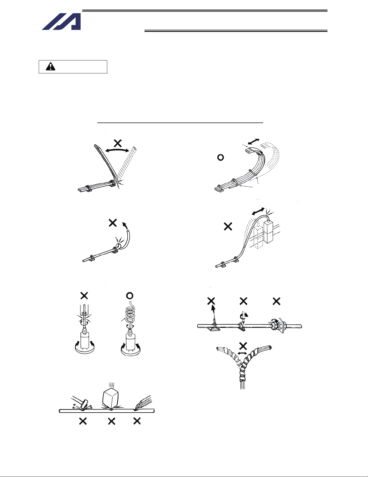
Prohibited Handling of Cables
Caution
When designing an application system using actuators and controllers, incorrect wiring or connection of
each cable may cause unexpected problems such as a disconnected cable or poor contact, or even a
runaway system. This section explains prohibited handling of cables. Read the information carefully to
connect the cables properly.
Ten Rules for Handling Cables (Must be Observed!)
1. Do not let the cable flex at a single point.
2. Do not let the cable bend, kink or twist.
4. Do not let the cable receive a turning force at a
single point.
Steel band
(piano wire)
Bundle loosely.
3. Do not pull the cable with a strong force.
5. When fixing the cable, provide a moderate slack
and do not tension it too tight.
Use a curly
cable.
6. Do not pinch, drop a heavy object onto or cut the
cable.
Do not use a spiral tube where
the cable flexes frequently.
Pre-7
Page 18

Introduction
INTELLIGENT ACTUATOR
7. Do not let the cable get tangled or kinked in a cable track or flexible tube. When bundling the cable,
keep a certain degree of flexibility (so that the cable will not become too taut when bent).
8. Do not cause the cables to occupy more than
60% of the space in the cable track.
Cable track
Cable
10. Always use a robot cable
if the cable is likely to flex significantly.
9. Do not lay signal lines together with circuit lines
that create a strong electric field.
Power line
Duct
Signal lines (flat cable)
[Standard structure of cable]
The standard structure of
Cover
Signal line (copper + tin)
cable will vary depending on
the manufacturer and type of
cable.
Protective layer
Shield
Absorbing material (When the
cable is bent, this material is
crushed by the surrounding signal
lines to maintain the shape of the
signal lines.)
Need for Robot Cables
A cable connected to a moving part of an actuator system will inevitably receive repeated bending loads at
the base of the cable. As a result, the cores in the cable may break over time. To minimize the risk of
cable breakage, we strongly recommend that a robot cable
offering significantly higher flexibility be used
in this type of application.
Pre-8
Page 19

INTELLIGENT ACTUATOR
Page 20
n
Introduction
INTELLIGENT ACTUATOR
Introduction
Thank you for purchasing the X-SEL Controller.
Inappropriate use or handling will prevent this product from demonstrating its full function and may even
cause unexpected failure or result in a shortened service life. Please read this manual carefully, and
handle the product with due care and operate it correctly. Keep this manual in a safe place and reference
relevant items when needed.
The X-SEL Controller you have purchased is a new-generation controller that uses a 32-bit RISC
(Reduced Instruction Set Computer) CPU and an advanced version of the proven “SEL” language to
perform a range of high functions such as multi-tasking, sequencer-less operation, palletizing function and
pseudo-sequence function.
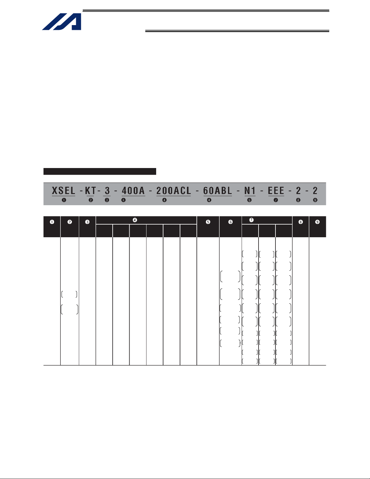
Refer to the table below for the details of models.
Model
Series
name
XSEL
Controller
type
KT
Global
specification
KET
CE-compliant
global
specification
Number of
axes
1
(1 axis)
2
(2 axis)
3
(3 axis)
4
(4 axis)
Motor
wattage
20
(20 W)
30D
(DS type,
30 W)
30R
(RS type,
30 W)
60
(60 W)
100
(100 W)
150
(150 W)
200
(200 W)
300
(300 W)
400
(400 W)
600
(600 W)
750
(750 W)
(Axis 1) (Axis 3)
Details of Axes 1 to 6
type
A
I
Brake
Blank
(Without
brake)
B
(With brake)
(With creep
Encoder
(Incremental)
(Absolute)
Creep
sensor
Blank
(Witho ut
creep
sensor)
C
sensor)
(Axis 2)
Home
sensor
(LS)
Blank
(Without
home
sensor)
L
(With h ome
sensor)
Synchro
specification
Blank
(Witho ut
synchro)
M
(Master axis
specification)
S
(Slave axis
specification)
Network
(dedicated
slot)
(None)
Standard I/O
(Slot 1)
N1
Expansion PIO
32 inputs/16
outputs
NPN board
P1
Expansion PIO
32 inputs/16
outputs
PNP board
DV
DeviceNet 256/256
board
CC
CC-Link
256/256 board
PR
ProfiBus
256/256 board)
ET
Ethernet
ata communicatio
board
Slot 2
E
(not used)
C
CC-Link
connection
16/16 board
N1
Expansion I/O
32 inputs/
16 outputs
NPN board
N2
Expansion I/O
16 inputs/
32 outputs
NPN board
N3
Expansion I/O
48 inputs/
48 outputs
NPN board
P1
Expansion I/O
32 inputs/
16 outputs
PNP board
P2
Expansion I/O
16 inputs/
32 outputs
PNP board
P3
Multi-point I/O
PNP 48/48
SA
Expansion SIO
Type A
SB
Expansion SIO
Type B
SC
Expansion SIO
Type C
Expansion I/O slot
Slot 3 Slo t 4
E
(not used)
C
CC-Link
connection
16/16 board
N1
Expansion I/O
32 inputs/
16 outputs
NPN board
N2
Expansion I/O
16 inputs/
32 outputs
NPN board
N3
Expansion I/O
48 inputs/
48 outputs
NPN board
P1
Expansion I/O
32 inputs/
16 outputs
PNP board
P2
Expansion I/O
16 inputs/
32 outputs
PNP board
P3
Multi-point I/O
PNP 48/48
SA
Expansion SIO
Type A
SB
Expansion SIO
Type B
SC
Expansion SIO
Type C
E
(not used)
C
CC-Link
connection
16/16 board
N1
Expansion I/O
32 inputs/
16 outputs
NPN board
N2
Expansion I/O
16 inputs/
32 outputs
NPN board
N3
Expansion I/O
48 inputs/
48 outputs
NPN board
P1
Expansion I/O
32 inputs/
16 outputs
PNP board
P2
Expansion I/O
16 inputs/
32 outputs
PNP board
P3
Multi-point I/O
PNP 48/48
SA
Expansion SIO
Type A
SB
Expansion SIO
Ty
pe B
SC
Expansion SIO
Type C
I/O flat
cable
length
2: 2 m
(standard)
3: 3 m
5: 5 m
0: None
Power-
supply
voltage
2: Singlephase 200 V
1
Page 21

Introduction
INTELLIGENT ACTUATOR
The X-SEL Controller is available with one to four axes. As with the conventional SEL Controller, it can be
used with various actuators. When connecting actuators, always use dedicated cables.
Actuator duty
IAI recommends that our actuators be used at a duty of 50% or less in view of the relationship of
service life and precision. The duty is calculated by the formula below:
Duty (%) =
hours Operating
X 100
hours Stopped hours Operating
After turning off the main power, be sure to wait for at least 5 seconds before turning it on.
Any shorter interval may generate “E88: Power system error (Other).”
Do not plug in/out the connectors while the power is still supplied to the controller. Doing so may result
in malfunction.
Item to note when installing the absolute-data backup battery (absolute specification)
The battery installation procedure specified below must be followed to initialize the battery circuit and
thereby prevent premature consumption of the battery. Install the battery according to this procedure:
[1] Connect the encoder cable.
[2] Turn on the power.
[3] Install the absolute-data backup battery.
The above operation must be performed every time the encoder cable was unplugged to relocate the
system, etc.
Read the operation manual for each actuator. If you have purchased our optional PC software and/or
teaching pendant, read the respective operation manuals, as well.
* Utmost effort has been made to ensure that the information contained in this manual is true and
correct. However, should you find any error or if you have any comment regarding the content,
please contact IAI.
2
Page 22

Part 1 Installation
INTELLIGENT ACTUATOR
Part 1 Installation
Caution
Chapter 1 Safety Precautions
The X-SEL Controller can be combined with a maximum of four actuators of different types, and is able to
provide integrated control over the entire system including peripherals. In other words, the X-SEL
Controller has the ability to control systems of all sizes ranging from a small system to a large factory
automation system. In general, however, the occurrence rate of accidents due to wrong operation or
carelessness will rise as the system becomes larger and more complex. Please give due consideration to
safety measures.
This system product was developed as a drive unit for an automated machine, etc., and as such the
maximum torque and speed are limited to levels acceptable for an automatically driven machine. However,
strict observance of the following items is requested to prevent unforeseen danger. Also read the
appendix entitled, “Safety Rules and Others.”
1. Do not handle this product in manners not specified in this manual. If you have any question regarding
the content of this manual, please contact IAI.
2. This controller is designed to perform all cutoff controls of the motor drive power to actuate an
emergency stop, enable the controller operation, etc., using an external circuit. Be sure to provide a
drive-power cutoff circuit externally to the main controller circuit.
The customer must determine and install an appropriate safety circuit meeting the required safety
category according to the operating condition of the final system.
The motor drive-power circuit has no built-in protective element such as a fuse. The customer must
provide appropriate circuit protection.
3. Always use the specified, genuine IAI cables for wiring between the controller and the actuator.
4. Do not enter the operation area of the machine while the machine is operating or ready to operate (the
controller power is on). If the machine is used in a place accessible to other people, provide an
appropriate safety measure such as enclosing the machine with a cage.
5. When assembling/adjusting or maintaining/inspecting the machine, always turn off the controller power
at the source beforehand. The operator should display in a conspicuous place a plate or other sign
saying that operation is in progress and that the power should not be turned on. The operator should
keep the entire power cable beside him or her to prevent another person from inadvertently plugging in
the cable.
6. When two or more operators are to work together, set call-out signals to ensure safety of all personnel
during the work. In particular, a person turning on/off the power or moving an axis—either via a motor
or manually—must always say what he or she is going to do out loud and confirm the responses from
the others first before actually performing the operation.
3
Page 23

Part 1 Installation
INTELLIGENT ACTUATOR
Chapter 2 Warranty Period and Scope of Warranty
The X-SEL Controller you have purchased passed our strict outgoing inspection. This unit is covered by
the following warranty:
1. Warranty Period
The warranty period shall be either of the following periods, whichever ends first:
18 months after shipment from our factory
12 months after delivery to a specified location
2. Scope of Warranty
Should the product fail during the above period under a proper use condition due to a fault on the part
of the manufacturer, IAI will repair the defect free of charge. However, the following cases are
excluded from the scope of warranty:
Discoloration of paint or other normal aging
Wear of consumable parts due to use
Subjective imperfection, such as noise not affecting mechanical function
Defect caused by inappropriate handling or use by the user
Defect caused by inappropriate or erroneous maintenance/inspection
Defect caused by use of a part other than IAI’s genuine part
Defect caused by unauthorized modification, etc., not approved by IAI or its agent
Defect due to an act of God, accident, fire, etc.
The warranty covers only the product as it is delivered. IAI shall not be liable for any loss arising in
connection with the delivered product. The user must bring the defective product to our factory to
receive a warranty repair.
3. Scope of Service
The price of the delivered product does not include costs incurred in association with program
generation, dispatch of technician, etc. Therefore, a separate fee will be chargeable in the following
cases even during the warranty period:
Guidance on installation/adjustment and witnessing of test operation
Maintenance/inspection
Technical guidance and training on operation, wiring method, etc.
Technical guidance and training regarding programs, such as program generation
Other services and operations where IAI finds a need to charge a separate fee
4
Page 24

Part 1 Installation
INTELLIGENT ACTUATOR
Chapter 3 Installation Environment and Noise Measures
1. Installation Environment
*1
As for the use environment, this product can be used in an environment of pollution degree 2
equivalent.
*1 Pollution degree 2: Normally only non-conductive pollutants exist, which are expected to be
temporarily conductive due to condensation. (IEC60664-1)
(1) When installing and wiring the controller, do not block the ventilation holes provided for cooling.
(Insufficient ventilation will not only prevent the product from functioning fully, but it may also result in
failure.)
(2) Prevent foreign matter from entering the controller through the ventilation holes. Since the controller is
not designed as dustproof or waterproof (oilproof), avoid using it in a dusty place or place subject to
oil mist or splashed cutting fluid.
(3) Do not expose the controller to direct sunlight or radiant heat from a high heat source such as a heat-
treating furnace.
(4) Use the controller in a non-condensing environment free from corrosive or inflammable gases.
(5) Use the controller in an environment where it will not receive external vibration or impact.
(6) Prevent electrical noise from entering the controller or its cables.
or
Environmental Condition of Controller
noitacificepS metI
Surrounding air temperature range
Forced air-cooling
Surrounding humidity range 30% ~ 85%
Storage temperature range
Dust protection structure IP20
Power-source voltage 230 VAC, single-phase
Operating power-source voltage
Rated operating power-source
frequency
24 VDC fan x 5 (2-axis type)
24 VDC fan x 6 (4-axis type)
0?C ~ 40?C
-10?C ~ 65?C
? 10%
50 Hz/60 Hz
2. Heat Radiation and Installation
Design the control panel size, controller layout and cooling method so that the surrounding air
temperature around the controller will be kept at or below 40°C.
Install the controller vertically on a wall, as illustrated below. The controller will be cooled by forced
ventilation (exhaust air will be discharged from the top). Be sure to install the controller in the
aforementioned direction and provide a minimum clearance of 150 mm above and 150 mm below the
controller.
If multiple controllers are to be installed side by side, providing additional suction fans on top of the
controllers will help maintain a uniform surrounding air temperature.
Provide a minimum clearance of 150 mm between the front side of the controller and a wall
(enclosure).
5
Page 25

Part 1 Installation
INTELLIGENT ACTUATOR
Airflow direction
Fan
150 mm min.
150 mm
min.
150 mm min.
Airflow
If multiple controllers are to be connected on top of one another, prevent the controller above from
taking in the exhaust air from the controller below.
3. Power Source
Provide a 230-VAC, single-phase power source.
4. Noise Measures and Grounding
(1) Wiring and power source
PE on the power terminal block is used for protective grounding. Provide Class D grounding from this
terminal.
Use a grounding cable with a wire size of 1.0 mm
than the AC power cable.
Install an AC line noise filter to prevent noise generating in the controller from traveling through the
power line to affect other devices.
230-VAC power source
Class D grounding
(protective grounding)
Drivepower
cutoff
control
circuit
Install a noise filter (MXB-1210-33 by Densei-Lambda) near the power connector on the X-SEL controller
side.
2
(#AWG17) or more, which should not be smaller
X-SEL controller
C.POWER M.POWER
N
L
N
L
Noise
filter
Accessory
6
Page 26

Part 1 Installation
INTELLIGENT ACTUATOR
* Notes on wiring method
Use twisted cables for the AC power cable and 24-VDC external power cable. Wire the controller
cables separately from lines creating a strong electric field such as power circuit lines (by not bundling
them together or placing in the same cable duct).
If you wish to extend the motor cable or encoder cable beyond the length of each supplied cable,
please contact IAI.
(2) Noise-elimination grounding
C.POWER
AC power source
N
L
PE
Connect the FG terminal
with the metal enclosure
using a cable of a maximum
allowable size over the
shortest distance.
Class D grounding
Metal enclosure
Provide a dedicated grounding of the FG or PE grounding point.
X-SEL
controller
Other
equipment
X-SEL
controller
Other
equipment
Do not use this method.
(3) Noise sources and noise elimination
There are many noise sources, but solenoid valves, magnet switches and relays are of particular
concern when building a system. Noise from these parts can be eliminated using the measures
specified below:
a. AC solenoid valve, magnet switch, relay
Measure --- Install a surge killer in parallel with the coil.
Surge killer
Point
Wire from each coil over the shortest distance.
Installing a surge killer on the terminal block,
etc., will be less effective because of a longer
distance from the coil.
7
Page 27

Part 1 Installation
INTELLIGENT ACTUATOR
b. DC solenoid valve, magnet switch, relay
Measure --- Install a diode in parallel with the coil. Determine the diode capacity in accordance with
the load capacity.
In a DC circuit, connecting a diode in reversed polarity will
damage the diode, internal parts of the controller and DC
power supply. Exercise due caution.
Diode
The above noise elimination measures are particularly important when a 24-VDC relay is driven
directly by a controller output and there is also a 100-VAC solenoid valve, etc.
Reference Circuit Diagram
Controller
OUT
COM
CR
+24 V
0 V
100 VAC
CR
SOL
Surge absorber
0 V
Solenoid valve
8
Page 28

Part 1 Installation
INTELLIGENT ACTUATOR
Chapter 4 Name and Function of Each Part
1. Front View of Controller
4-axis type
(5)
(6)
RB
CONTROLLER
M4
C.POWER
FUSE
M.POWER
LS4M3LS3M2LS2M1LS1
PG1
BK1
PG2
BK2
(1)
(2)
(3)
(4) (8)
(9)
(10) (18)
(1) FG terminal
This terminal is used to ground FG on the enclosure. The enclosure is
connected to PE in the AC input part inside the controller.
FG Terminal Specifications
Item Overview
M4 3-point SEMS screw, 5 mm
Cable size 2.0 ~ 5.5 mm2
Grounding method Class D grounding
(2) Fuse holder
This half-cut fuse holder is used to protect overcurrent in the AC controlpower input part.
It prevents inflow of abnormal current generated by ground fault, etc., and
uses a slow-blow fuse specified by IAI.
Overview of Fuse Holder Specifications
Item Description
Holder F-220-01A2 by Sato Parts
Fuse type SG5013 3.15 by Sky Gate
Melting characteristics Time lag type
(11)
PG3
BK3
I/O1 I/O2 I/O3 I/O4
PG4
BK4
(12) (13) (14)
CODE
MODE
TP
HOST
(19)
(15)
(16)
(17)
9
Page 29

INTELLIGENT ACTUATOR
(3) AC control-power
input connector
AC Control-Power Input Connector Specifications
Connector name C.POWER
Connector GMSTB2.5/3-STF-7.62 by Phoenix Contact
Supported cable size 1.25 ~ 2.5 mm2 (AWG12 ~ 16)
Connected to AC power source
Terminal assignments
(4) AC motor drive-power
input connector
AC Motor Drive-Power Input Connector Specifications
Connector name M.POWER
Connector PC4/2-7.62
Supported cable size 1.25 ~ 2.5 mm2 (AWG12 ~ 16)
Connected to
Terminal assignments
(5) External regenerative
unit connector
External Regenerative Unit Connector Specifications
Connector name RB
Connector GIC2.5/3-STF-7.62 by Phoenix Contact
Cable size 1.0 mm2 (AWG17 or equivalent), included in the
Connected to External regenerative box
Terminal assignments
Part 1 Installation
An input connector for 230-VAC, single-phase control power.
Item Overview
3-pin, 2-piece connector
N AC power input, N side
L AC power input, L side
PE (Protective grounding line)
An input connector for 230-VAC, single-phase motor drive power.
Item Overview
2-pin, 2-piece connector
AC power source (Noise filter, drive-power cutoff
control circuit)
N AC power input, N side
L AC power input, L side
This connector is used to connect a regenerative resistance unit that may
be required when the controller is used in a high-speed/high-load
environment, etc., and the built-in regenerative resistance capacity is not
sufficient. Whether or not an external regenerative resistance is necessary
will be determined by the specific application such as axis configuration.
Item Overview
3-pin, 2-piece connector
external regenerative box
Grounding terminal
10
RB– Regenerative resistance –
RB+
Regenerative resistance + (Motordriving DC voltage)
An insufficient regenerative resistance capacity will cause “E65, F63:
Regenerative resistance temperature error.” An insufficient regenerative
resistance capacity is also suspected when “E88: Power system error (Other)”
occurs.
Page 30

INTELLIGENT ACTUATOR
(6) Motor connector
Overview of Motor Connector Specifications
Connector name M
Connector GIC2.5/4-STF-7.62 by Phoenix Contact
Cable Dedicated motor cable
Connected to Actuator
Terminal assignments
(7) Axis-sensor
connector
Axis-Sensor Connector Specifications
Connector name LS
Connector MC1.5/6-ST-3.5 by Phoenix Contact
Cable Dedicated LS cable
Connected to Actuator
Terminal assignments
(8) Absolute-data backup
battery
Battery Capacity: 1000 mAh
Current consumption
Operating
Power is off
Absolute-Battery Connector Specifications
Connector name BAT
Connector 3-pin connector
Connected to Absolute-data battery unit by IAI
Part 1 Installation
This connector is used to drive the motor inside the actuator.
Item Description
4-pin, 2-piece connector
PE (Protective grounding line)
U Motor-driving phase U
V Motor-driving phase V
W Motor-driving phase W
This connector is used to connect axis sensors such as LS, CREEP and
OT.
Item Description
6-pin, 2-piece connector
24VOUT 24-V power source for driving contacts
0V 24-V ground
LS LS-contact input
CREEP CREEP-contact input
OT OT-contact input
When an absolute encoder is used, this battery unit will be used to back up
the encoder data. Nothing is connected here for a non-absolute axis.
Model: IA-XAB-BT
3 A
100 A
Item Description
03JQ-ST by Nichiatu
11
Page 31

Part 1 Installation
INTELLIGENT ACTUATOR
(9) Brake switch
This alternate switch with lock is used to release the axis brake. To operate
the switch, pull it toward you and tilt.
Tilting the switch upward (RLS side) will release the brake forcibly, while
tilting it downward (NOM) will enable an automatic brake control by the
controller.
(10) Axis-driver status
LEDs
These LEDs monitor the operating status of the driver CPU that controls the
motor drive. The following three LEDs are provided.
Name Color Meaning when lit
An error is detected by the driver. Although this LED
ALM Orange
flashes when the power limiter level is exceeded, this does
not indicate a problem as long as no error is present.
SVON Green The servo is on and the motor is being driven.
BAT ALM Orange The voltage of the absolute-data backup battery is low.
(11) Encoder connector
This 15-pin, D-sub connector is used to connect the actuator’s encoder.
Encoder Connector Specifications
Item Description
Connector name PG
Connector High-density D-sub, 15-pin (female)
Maximum
connection distance
Interface standard Conforming to RS422
Connected to Actuator
Connection cable
Terminal
assignments
10 m
(Built-in encoder unit inside the actuator)
Dedicated PG cable
Pin No. Signal name Description
1 A+ Phase-A differential + input (Phase U+)
2 A– Phase-A differential – input (Phase U–)
3 B+ Phase-B differential + input (Phase V+)
4 B– Phase-B differential – input (Phase V–)
5 Z+ Phase-Z differential + input (Phase W+)
6 Z– Phase-Z differential – input (Phase W–)
7 SRD+
8 SRD–
9 BATT Backup-battery power supply
10 BATTGND Battery ground
11 VCC Encoder power source
12 GND GND
13 BK–
14 BK+
15 FG Not used
Send/receive line+ (Pulse/magneticpole switching+)
Send/receive line– (Pulse/
magnetic-pole switching–)
Brake output
12
Page 32

Part 1 Installation
INTELLIGENT ACTUATOR
(12) System I/O connector
This connector is used to connect an emergency-stop switch, ENABLE
contact, ready relay, etc.
Connector MC1.5/6-ST-3.5 by Phoenix Contact; 6-pin, 2-piece connector
Terminal assignments
Pins +24V OUT and EMG IN form a contact-B emergency-stop input. Operation is enabled
when the pins are shorted.
Pins +24V OUT and EMG IN form a contact-B safety-gate input. Operation is enabled
when the pins are shorted.
Pins RDY OUT form a contact-A output that turns ON under the following condition:
SYSRDY is output (software = PIO trigger program can be run) and hardware is normal
(emergency stop is not being actuated and hardware error is not being detected).
+24-V OUT and EMG IN, and +24 V OUT and ENB IN, are shorted by a cable before the
shipment.
+24V OUT +24-V power output for emergency stop
EMG IN Emergency-stop input
+24V OUT +24-V power output for safety gate
ENB IN Safety-gate input
RDY OUT
RDY OUT
Ready-status output contact
(13) I/O24V power
connector
This connector is used to externally supply I/O power to the insulated part
when DI and DOs are mounted in the I/O connectors explained in (18) and
(19) (2-pin, 2-piece connector by Phoenix Contact). 24 V must be supplied
externally.
Supported cable size 0.75 ~ 1.25 mm
Connector MC1.5/6-ST-3.5 by Phoenix Contact; 2-pin, 2-piece connector
Terminal assignments
2
(AWG16)
24VIN +24-V power input for I/Os
0V I/O GND
(14) Panel window This window consists of a 4-digit, 7-segment LED display and five LED
lamps that indicate the status of the equipment.
For the information shown on the display, refer to 2, “Explanation of Codes
Displayed on the Panel Window” or the “Error Code Table.”
Meanings of Five LEDs
Name Status when the LED is lit
RDY CPU ready (program can be run)
ALM CPU alarm (system-down level error), CPU hardware error
EMG
PSE Power-system hardware error
CLK System clock error
Emergency stop has been actuated, CPU hardware error, power-system hardware error
(15) Mode switch This alternate switch with lock is used to command a controller operation
mode. To operate the switch, pull it toward you and tilt.
Tilting the switch upward will select MANU (manual mode), while tilting it
downward will select AUTO (auto mode). Teaching can be performed only
in the MANU mode, but auto program start is not enabled in the MANU
mode.
(Refer to the types of manual operations explained on p. 348.)
13
Page 33

INTELLIGENT ACTUATOR
(16) Teaching-pendant
connector
Interface Specifications of Teaching Serial Interface
Connector name TP
Connector DSUB-25 XM3B-2542-502L (Omron)
Communication method RS232C-compliant, start-stop synchronous method
Baud rate 38.4 kbps max.; half-duplex communication
Maximum connection
distance
Interface standard RS232C
Connected to X-SEL teaching pendant
Interface Specifications of Teaching Serial Interface
Part 1 Installation
When an optional teaching pendant or PC is connected, this D-sub, 25-pin
connector will be used to input program and position data in the MANU
mode.
Item Description
10 m (38.4 kbps)
Item No. Direction Signal name Description
Terminal
assignments
1 FG Frame ground
2 Out TXD Transmitted data
3 In RXD Received data
4 Out RTS Request to send
5 In CTS Clear to send
6 Out DSR Equipment ready
7 SG Signal ground
8
9 In Connection prohibited
10 In Connection prohibited
11
12 Out EMGOUT Emergency stop
13 In EMGIN
14
15 Out Connection prohibited
16 Out Connection prohibited
17 Out Connection prohibited
Power output
18 Out VCC
(5-V power source for teaching
pendant)
19 In ENBTBX Enable input
20 In DTR Terminal ready
21
22
23 Out EMGS Emergency-stop status
24
25 SG Signal ground
14
Page 34

INTELLIGENT ACTUATOR
(17) PC connector
This D-sub, 9-pin connector is used to perform serial communication
(RS232C) with the host equipment when AUTO is selected as the operation
mode.
* (16) and (17) cannot be used simultaneously.
RS232 Host Connector Specifications
This connector is used to establish a serial connection with a PC or PLC to enable
controller control.
Item Description
Connector name HOST
Connector D-sub, 9-pin (DTE); XM2C-0942-502L by Omron
Maximum connection
distance
Interface standard RS232C
Connected to AT-compatible PC, etc. (half-duplex communication)
Connection cable Dedicated cable
Terminal assignments
10 m (38.4 kbps)
Pin No. I/O Signal name Description
1 NC
2 In RD Received data (RXD)
3 Out SD Transmitted data (TXD)
4 In DR Data set ready (DSR)
5 In SG Signal ground
6 Out ER Equipment ready (DTR)
7 Out RS Request to send (RTS)
8 In CS Clear to send (CTS)
9 NC Not used
A dedicated cable must be used if an AT-compatible PC is to be connected.
The PC connector (D-sub, 9-pin) (17) will become available for use by the user
only when the teaching-pendant connector (D-sub, 25-pin) (16) is not in use.
The PC connector (D-sub, 9-pin) (17) and teaching-pendant connector (D-sub,
25-pin) (16) cannot be used simultaneously. Setting the mode switch (15) to
MANU will select the teaching-pendant connector (16), while setting it to AUTO
will select the PC connector (17).
Part 1 Installation
(18) Standard I/O
connector
This connector consists of a 50-pin flat connector and comprises 32input/16-output DIOs.
Overview of Standard I/O Interface Specifications
Item Description
Connector name I/O
Connector Flat connector, 50-pin
Power supply
Input 32 points (including general-purpose and dedicated inputs)
Output 16 points (including general-purpose and dedicated outputs)
Connected to External PLC, sensor, etc.
Power is supplied through the I/O24V power connector
(13).
15
Page 35

INTELLIGENT ACTUATOR
The functions are at the time
of shipment. The functions
assigned to port Nos. 000 to
015, 300 to 308, 313 and 314
can be changed via I/O
parameters. (Refer to Nos.
30 to 54, No. 59 and No. 60
in 1, “I/O Parameters,” of
Appendix, “List of
Parameters.”)
(19) Expansion I/O
connectors
Part 1 Installation
Standard I/O Interface List
Pin No. Category Port No. Function Cable color
1 -
2 000
3 001
4 002
5 003
6 004
7 005
8 006
9 007
10 008
11 009
12 010
13 011
14 012
15 013
16 014
17 015
18 016
19 017
20 018
21 019
22 020
23 021
24 022
25 023
26 024
27 025
28 026
29 027
30 028
31 029
32 030
33
34 300
35 301
36 302
37 303
38 304
39 305
40 306
41 307
42 308
43 309
44 310
45 311
46 312
47 313
48 314
49 315
50
Input
Output
NC Brown-1
Program start Red-1
General-purpose input Orange-1
General-purpose input Yellow-1
General-purpose input Green-1
General-purpose input Blue-1
General-purpose input Purple-1
General-purpose input Gray-1
Program specification (PRG No. 1) White-1
Program specification (PRG No. 2) Black-1
Program specification (PRG No. 4) Brown-2
Program specification (PRG No. 8) Red-2
Program specification (PRG No. 10) Orange-2
Program specification (PRG No. 20) Yellow-2
Program specification (PRG No. 40) Green-2
General-purpose input
General-purpose input
General-purpose input
General-purpose input
General-purpose input
General-purpose input
General-purpose input
General-purpose input
General-purpose input
General-purpose input
General-purpose input
General-purpose input
General-purpose input
General-purpose input
General-purpose input
General-purpose input
General-purpose input
General-purpose input
031
Alarm output Yellow-4
Ready output Green-4
Emergency-stop output Blue-4
General-purpose output
General-purpose output
General-purpose output
General-purpose output
General-purpose output
General-purpose output
General-purpose output
General-purpose output
General-purpose output
General-purpose output
General-purpose output
General-purpose output
General-purpose output
NC Black-5
-
Blue-2
Purple-2
Gray-2
White-2
Black-2
Brown-3
Red-3
Orange-3
Yellow-3
Green-3
Blue-3
Purple-3
Gray-3
White-3
Black-3
Brown-4
Red-4
Orange-4
Purple-4
Gray-4
White-4
Black-4
Brown-5
Red-5
Orange-5
Yellow-5
Green-5
Blue-5
Purple-5
Gray-5
White-5
These connectors are used to install I/O expansion boards.
16
Page 36

Part 1 Installation
INTELLIGENT ACTUATOR
2. Explanation of Codes Displayed on the Panel Window
2-1. Application
Display Priority (*1) Description
1
1 System-down level error
2 Writing data to the flash ROM.
3 Emergency stop is being actuated (except during the update mode).
4 Safety gate is open (except during the update mode).
5 Cold-start level error
5 Cold-start level error
5 Operation-cancellation level error
AC power is cut off (including momentary power failure or drop in
power-source voltage).
5 Operation-cancellation level error
6
6
Waiting for a drive-source cutoff reset input (except during the
update mode).
Operation is in pause (waiting for restart) (except during the update
mode).
7 All servo axes are interlocked (except during the update mode).
8 Message level error
8 Message level error
9 Core update mode
9 Core update is in progress.
9 Core update has completed.
9 Slave update mode
9 Slave update is in progress.
9 Slave update has completed.
9
Running a program (last started program); “No.” indicates program
number.
9 Initialization sequence number
9 Debug mode
9 Ready status (auto mode)
9 Ready status (manual mode)
10 Deadman switch OFF (manual mode)
(*1) The priority increases as the number decreases.
17
Page 37

INTELLIGENT ACTUATOR
2-2. Core
play Priority (*1) Description
Dis
1
AC power is cut off (including momentary power failure or drop in
power-source voltage).
1 Cold-start level error
1 Cold-start level error
1 Operation-cancellation level error
1 Operation-cancellation level error
2 Message level error
2 Message level error
2 Application update mode
2 Application update is in progress.
Part 1 Installation
2 Application update has completed.
2 Hardware test mode process
2 Clearing the application flash ROM.
2 Application flash ROM has been cleared.
2 Jump to the application
2 Core flash-ROM check process
2 Application flash-ROM check process
2 SDRAM check process
(*1) The priority increases as the number decreases.
18
Page 38

Part 1 Installation
INTELLIGENT ACTUATOR
Chapter 5 Specifications
1. Controller Specifications
Type
Number of controlled axes 1 axis 2 axes 3 axes 4 axes
Total output when maximum
number of axes are connected
Power-source voltage 230 VAC, single-phase
Operating power-source voltage
range
Power-source frequency 50 Hz/60 Hz
Insulation resistance
10 M min. (measured at 500 VDC between the power terminal and I/O
terminals and between the external terminals (together) and case)
Withstand voltage 1500 VAC for 1 minute (Note)
Surrounding air temperature
range
Surrounding humidity range 30% ~ 85%
Storage temperature range
Axis control method AC full digital servo
17-bit incremental encoder (wire-saving type)
Position detection methods
17-bit rotation data backup absolute encoder (wire-saving type)
(Both have a control resolution of 14 bits)
Batteries
For backup of absolute data: IA-XAB-BT
For backup of system memory: CR2032
Speed setting 1 mm/sec ~ 2000 mm/sec
Acceleration/deceleration setting 0.01 G ~ 1 G
Programming language Super SEL language
Program steps 6000 steps (total)
Number of positions 3000 positions (total)
Number of programs 64 programs
Multi-tasking 16 programs
Storage device Flash ROM + SRAM battery backup
Data input methods Teaching pendant or PC software
Standard inputs 32 points (total of dedicated inputs + general-purpose inputs)
Standard outputs 16 points (total of dedicated outputs + general-purpose outputs)
Expanded inputs/outputs 48 points per unit (A maximum of 3 units can be added)
Serial communication For connection of teaching pendant or PC
Other inputs/output Emergency-stop input, safety-gate input, system ready output
Motor overcurrent, overload, motor-driver temperature check, overload
Protective functions
check, encoder-open detection, soft limit over, system error, battery
Drive-source cutoff method External relay (Use a safety relay.)
Regenerative resistance
Built-in (220 , 80 W); external regenerative resistance supported
Accessory Relay box, noise filter, I/O flat cable
Optional parts and components
Note: The withstand voltage of the actuator motor is 1000 V for 1 minute.
When performing a withstand voltage test with the controller and actuator connected, make sure the test voltage and
duration will not exceed 1000 V and 1 minute, respectively.
Teaching pendant, PC software, absolute-data backup battery, I/O
shield cable, I/O expansion board
1600 W
10%
0C ~ 40C
-10C ~ 65C
error
19
Page 39

INTELLIGENT ACTUATOR
2. External I/O Specifications
2-1. NPN Specification
(1) Input
part
External Input Specifications (NPN Specification)
Item Specification
Input voltage
Input current 7 mA per circuit
ON/OFF voltage
Insulation method Photocoupler insulation
External devices
24 VDC 10%
ON voltage --- 16.0 VDC min.
OFF voltage --- 5.0 VDC max.
(1) No-voltage contact (minimum load of approx. 5 VDC/1 mA)
(2) Photoelectric/proximity sensor (NPN type)
(3) Sequencer transistor output (open-collector type)
(4) Sequencer contact output (minimum load of approx. 5 VDC/1 mA)
Internal circuit
* P24: I/O24V power connector, 24V IN
[Input circuit]
560
3.3 K
P24*
Input terminal
Part 1 Installation
+
External power
supply 24 VDC 10%
-
Caution
If a non-contact circuit is connected externally, malfunction may result from leakage
current. Use a circuit in which leakage current in a switch-off state does not exceed 1
mA.
X-SEL controller’s input signal
At the default settings, the system recognizes the ON/OFF durations of input signals if they
are approx. 4 msec or longer. The ON/OFF duration settings can also be changed using I/O
parameter No. 20 (input filtering frequency).
20
ON duration
OFF duration
Page 40

Part 1 Installation
INTELLIGENT ACTUATOR
(2) Output part
External Output Specifications (NPN Specification)
Item Specification
Load voltage 24 VDC
Maximum load current 100 mA per point, 400 mA per 8 ports Note)
Leakage current 0.1 mA max. per point
Insulation method Photocoupler insulation
External devices
Note) 400 mA is the maximum total load current of every eight ports from output port No. 300. (The
maximum total load current of output port No. 300 + n to No. 300 + n + 7 is 400 mA, where n is 0
or a multiple of 8.)
(1) Miniature relay
(2) Sequencer input unit
TD62084 (or equivalent)
[Output circuit]
Internal circuit
D
10
* P24: I/O24V power connector, 24V IN
* N: I/O24V power connector, 0V
P24*
Surge absorber
Load
Output terminal
N*
+
External power supply
24 VDC 10%
-
Caution
In the event that the load is short-circuited or current exceeding the maximum load
current is input, the overcurrent protection circuit will be actuated to cut off the circuit.
However, give due consideration to the circuit connection layout to prevent short-circuit
or overcurrent.
21
Page 41

INTELLIGENT ACTUATOR
2-2. PNP Specification
(1) Input
part
Item Specification
Input voltage
Input current 7 mA per circuit
ON/OFF voltage
Insulation method Photocoupler insulation
External devices
Internal circuit
Part 1 Installation
External Input Specifications (PNP Specification)
24 VDC 10%
ON voltage --- 8 VDC max.
OFF voltage --- 19 VDC min.
(1) No-voltage contact (minimum load of approx. 5 VDC/1 mA)
(2) Photoelectric/proximity sensor (PNP type)
(3) Sequencer transistor output (open-collector type)
(4) Sequencer contact output (minimum load of approx. 5 VDC/1 mA)
[Input circuit]
Input terminal
+
560
3.3 K
N*
* N: I/O24V power connector, 0V
-
External power
supply 24 VDC 10%
Caution
If a non-contact circuit is connected externally, malfunction may result from leakage
current. Use a circuit in which leakage current in a switch-off state does not exceed 1
mA.
X-SEL controller’s input signal
At the default settings, the system recognizes the ON/OFF durations of input signals if they
are approx. 4 msec or longer. The ON/OFF duration settings can also be changed using I/O
parameter No. 20 (input filtering frequency).
22
ON duration
OFF duration
Page 42

Part 1 Installation
INTELLIGENT ACTUATOR
(2) Output part
External Output Specifications (PNP Specification)
Item Specification
Load voltage 24 VDC
Maximum load current 100 mA per point, 400 mA per 8 ports Note)
Leakage current 0.1 mA max. per point
Insulation method Photocoupler insulation
External devices
Note) 400 mA is the maximum total load current of every eight ports from output port No. 300. (The
maximum total load current of output port No. 300 + n to No. 300 + n + 7 is 400 mA, where n is 0
or a multiple of 8.)
(1) Miniature relay
(2) Sequencer input unit
TD62784 (or equivalent)
[Output circuit]
Internal circuit
* P24: I/O24V power connector, 24V IN
* N: I/O24V power connector, 0V
10
Output terminal
P24
Surge absorber
Load
N
+
External power supply
24 VDC 10%
-
Caution
In the event that the load is short-circuited or a current exceeding the maximum load
current is input, the overcurrent protection circuit will be actuated to cut off the circuit.
However, give due consideration to the circuit connection layout to prevent short-circuit
or overcurrent.
23
Page 43

Part 1 Installation
INTELLIGENT ACTUATOR
3. Power-Source Capacity and Heat Output of the Controller
The power-source capacity and heat output of the controller can be obtained using the formulas
below:
Power-source capacity [VA] = {Motor drive power [W] + Control power-source
capacity [W]} Power factor [0.6]
Heat output [W] = Total sum of output stage losses [W] + Control power-source
capacity [W]
Motor Drive Power and Output Stage Loss
Actuator motor wattage Motor drive power [W] Output stage loss [W]
20 W 15.6 1.58
30 W 27.6 2.07
60 W 83.0 3.93
100 W 140.1 6.12
150 W 196.9 8.30
200 W 252.6 9.12
400 W 477.5 19.76
600 W 698.2 27.20
750 W 912.8 29.77
The control power-source capacity varies as follows, depending on the numbers of controller axes and
brake axes.
Control Power-Source Capacity
No BK BK X 1 BK X 2 BK X 3 BK X 4
1-axis controller [W] 17.5 27.3
2-axis controller [W] 23.4 33.2 42.9
3-axis controller [W] 29.3 39.1 48.8 58.6
4-axis controller [W] 35.3 45.0 54.8 64.5 74.3
(In the above table, the number of controller axes indicates the number of axes connectable to the controller. It is not
the number of axes actually connected.)
24
Page 44

Part 1 Installation
INTELLIGENT ACTUATOR
Calculation example)
A 3-axis controller with a brake, equipped with a 200-W actuator for axis 1, 200-W actuator for axis 2
and 100-W actuator for axis 3
Power-source capacity
The motor drive power is 252.6 W for axes 1 and 2 and 140.1 W for axis 3.
The control power-source capacity is calculated as 39.1 W for “3-axis controller/brake x 1.”
(252.6 + 252.6 + 140.1 + 39.1) 0.6 1141 [VA]
The power-source capacity is 1141 [VA].
Heat output
The output stage loss is 9.12 W for axes 1 and 2 and 6.12 W for axis 3.
The control power-source capacity is calculated as 39.1 W for “3-axis controller/brake x 1.”
(9.12 + 9.12 + 6.12) + 39.1 63 [W]
The heat output is 63 [W].
25
Page 45

INTELLIGENT ACTUATOR
4. External Dimensions
2-axis type (The external dimensions of 1-axis type and 2-axis type are the same.)
34.7
150
4-axis type (The external dimensions of 3-axis type and 4-axis type are the same.)
77.2
150
369.4
454.5
150
150
34.7
5
3 -
186
5
5
180
77.2
3 -
180
125.3
5
180
Part 1 Installation
195
125.3
195
26
Page 46

Part 1 Installation
INTELLIGENT ACTUATOR
Chapter 6 System Setup
A connection example of a 2-axis controller is given below:
1. Connection Method of Controller and Actuator (Standard Specification)
Note: If multiple controller axes are used, be careful not to connect the actuator cables and connectors
wrongly. Confirm the model type of the actuator connected to each connector. Wrong
connections of actuators and connectors may lead to motor or board damage or malfunction.
Note: In the case of an absolute specification, perform an absolute reset after the connection (refer to Chapter 7).
Class D grounding
(protective grounding)
AC power
source
ANSI-compatible teaching pendant
Drive-power cutoff
control circuit
Noise filter
ANSI-compatible
PC
PC cable
Dummy plug (AUTO)
Relay box
Connection cable
between relay box
and controller
PIO power, 24 VDC
PLC (host side)
27
Page 47

Part 1 Installation
INTELLIGENT ACTUATOR
(1) Connect to the controller the motor cable, encoder cable and LS cable (optional) from the
actuator.
(2) Connect the controller to the relay box using the supplied relay cable.
(3) Connect the relay box to the ANSI-compatible teaching pendant (or ANSI-compatible PC cable).
Set both the mode switch on the controller and the AUTO/MANU selector switch on the relay
box to MANU. (Refer to p. 34)
(4) Connect the safety I/O terminals on the relay box to the drive-power cutoff control circuit.
(5) Supply the power to the AC control-power input connector.
Caution
Be sure to turn on the motor power after turning on the control power.
(6) The panel window will display the code "rdy" to indicate that the preparation is complete.
If "ErG" is displayed, it means that an emergency-stop signal is being input.
In the case of an absolute specification, "ECA1" will be displayed. Refer to Chapter 7, "How to
Perform An Absolute Encoder Reset."
28
Page 48

Part 1 Installation
INTELLIGENT ACTUATOR
1.2 I/O Connection Diagrams
(1) NPN specification
0 V +24 V
Pin No. Category Port No. Function
Cable color
Input
Output
Program start
General-purpose input
General-purpose input
General-purpose input
General-purpose input
General-purpose input
General-purpose input
Program specification (PRG No.1)
Program specification (PRG No.2)
Program specification (PRG No.4)
Program specification (PRG No.8)
Program specification (PRG No.10)
Program specification (PRG No.20)
Program specification (PRG No.40)
General-purpose input
General-purpose input
General-purpose input
General-purpose input
General-purpose input
General-purpose input
General-purpose input
General-purpose input
General-purpose input
General-purpose input
General-purpose input
General-purpose input
General-purpose input
General-purpose input
General-purpose input
General-purpose input
General-purpose input
General-purpose input
Alarm output
Ready output
Emergency stop output
General-purpose output
General-purpose output
General-purpose output
General-purpose output
General-purpose output
General-purpose output
General-purpose output
General-purpose output
General-purpose output
General-purpose output
General-purpose output
General-purpose output
General-purpose output
Red-1
Orange-1
Yellow-1
Green-1
Blue-1
Purple-1
Gray-1
White-1
Black-1
Brown-2
Red-2
Orange-2
Yellow-2
Green-2
Blue-2
Purple-2
Gray-2
White-2
Black-2
Brown-3
Red-3
Orange-3
Yellow-3
Green-3
Blue-3
Purple-3
Gray-3
White-3
Black-3
Brown-4
Red-4
Orange-4
Yellow-4
Green-4
Blue-4
Purple-4
Gray-4
White-4
Black-4
Brown-5
Red-5
Orange-5
Yellow-5
Green-5
Blue-5
Purple-5
Gray-5
White-5
29
Page 49

Part 1 Installation
INTELLIGENT ACTUATOR
(2) PNP specification
+24 V 0 V
Pin No. Category Port No. Function
Cable color
Input
Output
Program start
General-purpose input
General-purpose input
General-purpose input
General-purpose input
General-purpose input
General-purpose input
Program specification (PRG No.1)
Program specification (PRG No.2)
Program specification (PRG No.4)
Program specification (PRG No.8)
Program specification (PRG No.10)
Program specification (PRG No.20)
Program specification (PRG No.40)
General-purpose input
General-purpose input
General-purpose input
General-purpose input
General-purpose input
General-purpose input
General-purpose input
General-purpose input
General-purpose input
General-purpose input
General-purpose input
General-purpose input
General-purpose input
General-purpose input
General-purpose input
General-purpose input
General-purpose input
General-purpose input
Alarm output
Ready output
Emergency stop output
General-purpose output
General-purpose output
General-purpose output
General-purpose output
General-purpose output
General-purpose output
General-purpose output
General-purpose output
General-purpose output
General-purpose output
General-purpose output
General-purpose output
General-purpose output
Red-1
Orange-1
Yellow-1
Green-1
Blue-1
Purple-1
Gray-1
White-1
Black-1
Brown-2
Red-2
Orange-2
Yellow-2
Green-2
Blue-2
Purple-2
Gray-2
White-2
Black-2
Brown-3
Red-3
Orange-3
Yellow-3
Green-3
Blue-3
Purple-3
Gray-3
White-3
Black-3
Brown-4
Red-4
Orange-4
Yellow-4
Green-4
Blue-4
Purple-4
Gray-4
White-4
Black-4
Brown-5
Red-5
Orange-5
Yellow-5
Green-5
Blue-5
Purple-5
Gray-5
White-5
30
Page 50

Part 1 Installation
INTELLIGENT ACTUATOR
1.3 I/O Flat Cable
Socket (with strain relief): XG4M-5030-T (Omron)
No. Color No. Color No. Color No. Color No. Color
1 Brown-1 11 Brown-2 21 Brown-3 31 Brown-4 41 Brown-5
2 Red-1 12 Red-2 22 Red-3 32 Red-4 42 Red-5
3 Orange-1 13 Orange-2 23 Orange-3 33 Orange-4 43 Orange-5
4 Yellow-1 14 Yellow-2 24 Yellow-3 34 Yellow-4 44 Yellow-5
5 Green-1 15 Green-2 25 Green-3 35 Green-4 45 Green-5
6 Blue-1 16 Blue-2 26 Blue-3 36 Blue-4 46 Blue-5
7 Purple-1 17 Purple-2 27 Purple-3 37 Purple-4 47 Purple-5
8 Gray-1 18 Gray-2 28 Gray-3 38 Gray-4 48 Gray-5
9 White-1 19 White-2 29 White-3 39 White-4 49 White-5
10 Black-1 20 Black-2 30 Black-3 40 Black-4 50 Black-5
Flat cable: KFX-50 (S) (Color) (Kaneko Cord)
Flat cable (50 cores)
No connector
31
Page 51

Part 1 Installation
INTELLIGENT ACTUATOR
2. Drive-Power Cutoff Control Circuit
This controller has no built-in drive-power cutoff control circuit to actuate an emergency stop, enable the
controller operation, etc. The customer must configure this circuit externally to the controller in accordance
with the safety category required by the final system. The table below lists the controller-side
inputs/outputs and units that are used to configure a drive-power cutoff control circuit.
Connector name Description
AC motor-power input
connector
System I/O connector
Teaching-pendant
connector
Unit name Description
Relay box
ANSI-compatible
teaching pendant
(SEL-TD, IA-T-XA)
This connector inputs the externally supplied motor power. Cut
off or reset this input using the drive-power cutoff control circuit
in response to an emergency-stop or enable operation.
This connector provides emergency-stop input, safety-gate
input and controller-ready contact output.
It is used as an interface between the external drive-power
cutoff control circuit and the controller.
Connect it to IAI's relay box. Connecting the teaching pendant
directly to this connector will disable drive-power cutoff action,
so exercise caution.
This interface unit connects IAI's teaching pendant to the
controller and serves as an interface for emergency-stop and
enable actions between the external drive-power cutoff control
circuit and the controller.
The relay box consists of D-Sub, 25-pin connectors for
controller and teaching pendant and a 2-piece connector for
drive-power cutoff control circuit interface.
This IP54 teaching pendant has a 3-position enable switch and
an emergency-stop switch. Use this teaching pendant if you
wish to configure a drive-power cutoff control circuit of category
1 or above.
Standard teaching
pendant
(SEL-T, IA-T-XD)
32
This teaching pendant can be used if the drive-power cutoff
control circuit only needs to conform to category B.
Page 52

INTELLIGENT ACTUATOR
2.1 System I/O Connector
The table bel
connector.
ow summarizes the detailed explanations of the respective terminals of the system I/O
RDY OUT1
1
RDY OUT2
2
Part 1 Installation
A dry contact indicating that the controller has started properly.
The contact capacity is 24 VDC, 1 A max.
Use this contact for safety circuit interlocking.
S.GATE IN
3
+24V OUT
4
EMG IN
5
+24V OUT
6
Note) 24V OUT in Nos. 4 and 6 is a dedicated output generated inside the controller. Never use
it for any other purpose.
A safety-gate operation monitor input signal that always remains
enabled regardless of the operating mode of the controller. The
contact-A input operates the actuator only in MAKE mode. Connect it to
the dry contact for safety-gate signal from the external safety circuit.
This input must be shorted if not used.
An emergency-stop operation monitor input signal. The contact-B input
actuates an emergency stop in BREAK mode. Short this input if a relay
box is used.
33
Page 53

INTELLIGENT ACTUATOR
2.2 Relay Box
Overview of Relay Box
(1)
The relay box is a unit needed to externally cut off the motor power input to the Global
Specification X-SEL Controller in response to an input action via the emergency-stop button or
deadman switch on the teaching pendant.
The relay box has a connector terminal block providing the contact outputs for emergency-stop
button and deadman switch. These contact outputs are used to cut off the drive power in
accordance with the pressing of the emergency-stop button or deadman switch on the teaching
pendant. (A circuit is required that cuts off the drive power the moment the contact output for
emergency-stop button or deadman switch becomes open.)
The connector terminal block also has terminals for inputting a drive-power cutoff condition such
as "emergency stop" or "enable" to the controller. By inputting an appropriate signal the moment
the drive power is cut off externally, the controller can perform appropriate processing such as
an emergency stop. (A circuit is required that inputs a drive-power cutoff condition such as
"emergency stop" or "enable" to the controller the moment the drive power is cut off.)
IAI's teaching pendant SEL-T and IA-T-XD provide a single contact that responds to both the
emergency-stop button and deadman switch. Therefore, the ANSI-compatible teaching pendant
SEL-TD and IA-T-XA providing two contact outputs must be used if you wish to configure a
control system meeting safety category 3 or 4.
(2) Names of Respective Parts of Relay Box, Connecting Destinations, and Descriptions
[4] [3]
[5]
[1]
[2]
Part 1 Installation
34
Page 54

INTELLIGENT ACTUATOR
1) Dedicated X-SEL Teaching Pendant Connector
Silkscreen printed
name
Connects the teaching pendant or PC cable. Or, a dummy plug
Connecting
destination,
description
may be connected.
Note: Two types of dummy plugs are supplied. Use a dummy
plug appropriate for the teaching pendant you are using.
(Refer to page 33.)
Connector D-Sub, 25-pin XM3B-2542-502L (Omron)
2) Relay Cable Connector for Relay Box
Silkscreen printed
name
Connecting
destination,
description
Connects the relay cable for relay box.
The relay cable is connected to the Global Specification X-SEL
Controller.
Connector D-Sub, 25-pin XM3B-2542-502L (Omron)
3) Safety I/O Terminals
Silkscreen printed
name
These terminals are wired to the external drive-power cutoff
control circuit.
Pins 1 to 8 serve as outputs for the various safety switch
Connecting
destination,
description
terminals provided on the teaching pendant.
Pins 9 to 12 are assigned to the emergency-stop signal and
deadman signal in the X-SEL teaching pendant terminals.
Pins 10 and 12 are supplied 24 V, just like the X-SEL system I/O
terminals. However, pins 10 and 12 must not be connected
together since they draw power from different circuits.
Connector MC1.5/12-ST-3.5 (Phoenix Contact)
Part 1 Installation
TP IN
TP OUT
(TO CONTROLLER)
SAFETY IN/OUT
35
Page 55

Part 1 Installation
INTELLIGENT ACTUATOR
Terminal Numbers and Descriptions of Safety I/O Terminals
Terminal number Description
(When the ANSI-compatible teaching pendant SEL-TD and IA-T-
1
2
3
4
5 Contact output 2 for deadman switch 1 on the teaching pendant
XA are used)
Contact output 2 for deadman switch 2 on the teaching pendant
(When the ANSI-compatible teaching pendant SEL-TD and IA-TXA are used)
Contact output 1 for deadman switch 2 on the teaching pendant
(When the ANSI-compatible teaching pendant SEL-TD and IA-TXA are used)
Contact output 2 for emergency-stop switch 2 on the teaching
pendant
(When the ANSI-compatible teaching pendant SEL-TD and IA-TXA are used)
Contact output 1 for emergency-stop switch 2 on the teaching
pendant
6 Contact output 1 for deadman switch 1 on the teaching pendant
7
8
9
10
11
12
Contact output 2 for emergency-stop switch 1 on the teaching
pendant
Contact output 1 for emergency-stop switch 1 on the teaching
pendant
Enable input to the X-SEL controller
(Closing pins 10 and 9 will enable the controller operation.)
24-V power output from the X-SEL controller
(Do not connect to pin 12.)
Emergency-stop input to the X-SEL controller
(Opening pins 12 and 11 will actuate an emergency-stop.)
24-V power output from the X-SEL controller
(Do not connect to pin 10.)
12 1
36
Page 56

INTELLIGENT ACTUATOR
4) Internal Circuit Selector Terminals
Silkscreen printed
name
This connector terminal block is used to select internal circuits of
Description
the relay box.
The shorting connections between the connector terminals are
changed in accordance with the teaching pendant used.
Connector MC1.5/6-ST-3.5 (Phoenix Contact)
Terminal Numbers and Descriptions of Internal Circuit Selector Terminals
Terminal number Description
Shorted to pin 2 when the ANSI-compatible teaching pendant SEL-
1
TD and IA-T-XA are used.
(Opened when the teaching pendant SEL-T and IA-T-XD are
used.)
Shorted to pin 1 when the ANSI-compatible teaching pendant SEL-
2
TD and IA-T-XA are used.
(Opened when the teaching pendant SEL-T and IA-T-XD are
used.)
Shorted to pin 4 when the teaching pendant SEL-T and IA-T-XD
3
are used.
(Opened when the ANSI-compatible teaching pendant SEL-TD is
used.)
Shorted to pin 3 when the teaching pendant SEL-T and IA-T-XD
4
are used.
(Opened when the ANSI-compatible teaching pendant SEL-TD
and IA-T-XA are used.)
Shorted to pin 6 when the teaching pendant SEL-T and IA-T-XD
5
are used.
(Opened when the ANSI-compatible teaching pendant SEL-TD
and IA-T-XA are used.)
Shorted to pin 5 when the teaching pendant SEL-T and IA-T-XD
6
are used.
(Opened when the ANSI-compatible teaching pendant SEL-TD
and IA-T-XA are used.)
When the teaching pendant
SEL-T and IA-T-XD are
used
6 1 6 1
When this wiring pattern is
used, use a dummy plug
for IAI’s teaching pendant.
Part 1 Installation
TP (ANSI/IAI) SELECT
When the ANSI-compatible teaching
pendant SEL-TD and IA-T-XA are
When this wiring pattern is
used, use a dummy plug
for ANSI-compliant
teaching pendant.
37
Page 57

Part 1 Installation
INTELLIGENT ACTUATOR
5) AUTO/MANU Selector Switch
Silkscreen printed
name
This switch selects the AUTO or MANU mode.
Description
Switch B-22LH (Nihon Kaiheiki)
Setting the switch knob to the AUTO side will short pins 1 and 2
and pins 5 and 6 of the safety I/O terminals 3).
AUTO/MANU
Caution
Set the knob of the controller's mode switch and that of the AUTO/MANU selector
switch to the same side.
38
Page 58

Part 1 Installation
INTELLIGENT ACTUATOR
(3) Teaching Pendant Operations and Safety I/O Terminal Conditions
1) Safety I/O Terminal (Pins 1 to 8) Conditions upon Pressing of Emergency-Stop Switch on
Teaching Pendant (TP)
Condition of emergency-stop switch on teaching pendant Pressed Released
Condition of AUTO/MANU switch on relay box AUTO MANU AUTO MANU
Safety I/O terminal pin number
1-2
(Contact outputs 1, 2 for enable switch 2 on the ANSI-
- - - -
compatible TP)
3-4
(Contact outputs 1, 2 for emergency-switch 2 on the
open open close close
ANSI-compatible TP)
5-6
(Contact outputs 1, 2 for enable switch 1 on the TP)
- - - -
7-8
(Contact outputs 1, 2 for emergency-stop switch 2 on the
open open close close
TP)
Once the teaching pendant is disconnected, the terminal conditions will become the same as those
when the emergency-stop switch is "Pressed" as shown in the table above. Set the knob of the
controller's mode switch and that of the AUTO/MANU selector switch to the same side.
2) Safety I/O Terminal (Pins 1 to 8) Conditions upon Pressing of Deadman Switch on Teaching
Pendant (TP)
Released
Condition of deadman switch on teaching pendant Pressed
(Pushed in
further)
Condition of AUTO/MANU switch on relay box AUTO MANU AUTO MANU
Safety I/O terminal pin number
Safety I/O terminal (pins 1 to 8)
conditions
1-2
(Contact outputs 1, 2 for deadman switch 2 on the ANSI-
close close close open
compatible TP)
3-4
(Contact outputs 1, 2 for emergency-switch 2 on the
- - - -
ANSI-compatible TP)
5-6
(Contact outputs 1, 2 for deadman switch 1 on the TP)
close close close open
7-8
(Contact outputs 1, 2 for emergency-stop switch 2 on the
- - - -
TP)
Once the teaching pendant is disconnected, the terminal conditions will become the same as those
when the deadman switch is "Released" as shown in the table above. Set the knob of the controller's
mode switch and that of the AUTO/MANU selector switch to the same side.
39
Page 59

Part 1 Installation
INTELLIGENT ACTUATOR
(4) Operations to Safety I/O Terminals and X-SEL Controller Conditions
1) X-SEL Controller Conditions upon Opening/Closing Safety I/O Terminal Pins 9 and 10 (Enable
Input and 24 V to X-SEL Controller)
Connection of teaching pendant to relay box Not connected
Condition of AUTO/MANU switch on X-SEL unit AUTO MANU
Condition of pins 9 and 10 open close open close
X-SEL condition (without dummy plug) Ardy Ardy dSF rdy
X-SEL condition (with dummy plug) Ardy Ardy dSF rdy
Connection of teaching pendant to relay box Connected
Condition of AUTO/MANU switch on X-SEL unit AUTO MANU
Condition of pins 9 and 10 open close open close
X-SEL condition Ardy Ardy dSF rdy
(Note) Set the knob of the controller's mode switch and that of the AUTO/MANU selector switch to
the same side.
2) X-SEL Controller Conditions upon Opening/Closing Safety I/O Terminal Pins 11 and 12
(Emergency-Stop Input and 24 V to X-SEL Controller)
Connection of teaching pendant to relay box Not connected
Condition of AUTO/MANU switch on X-SEL unit
(Note)
AUTO MANU
Condition of pins 11 and 12 open close open close
X-SEL condition (without dummy plug) Ardy Ardy EMG rdy
X-SEL condition (with dummy plug) EMG Ardy EMG rdy
Connection of teaching pendant to relay box Connected
Condition of AUTO/MANU switch on X-SEL unit AUTO MANU
Condition of pins 11 and 12 open close open close
X-SEL condition EMG Ardy EMG rdy
(Note) Set the knob of the controller's mode switch and that of the AUTO/MANU selector switch to
the same side.
40
Page 60

INTELLIGENT ACTUATOR
2.3 Drive-Power Cutoff Control Circuit
Connection Example of External Drive-Power Cutoff Control Circuit
(1)
The next page shows a sample connection circuit for cutting off the drive power externally for
each safety category. For the safety relay unit, the names and arrangements of terminals, etc.,
will vary depending on the manufacturer, so confirm them in the operating manual for the
product used.
The connections shown in this diagram cut off the drive power in accordance with the input from
the emergency-stop button, external emergency-stop button and deadman switch on the
teaching pendant.
(2) Notes
The customer must provide the contactors and safety relays to cut off the drive power.
Select contactors with a rated capacity of 10 A or above.
The noise filter for motor power input is supplied by IAI.
The power line cables must be at least 1.0 mm sq. in size.
Do not wire the signal cables such as I/O and emergency-stop cables together with the power
cables, but place them in separate ducts, etc., to provide a sufficient distance between them.
Provide an external circuit protector with a rated capacity of 10 A or above, in order to cut off
the drive power and control power simultaneously. (This circuit protector is not shown in the
diagram on the next page.)
If the drive power is cut off and turned on repeatedly, provide a minimum interval of 5
seconds between ON and OFF.
Do not supply the drive power with the control power cut off.
When the mode switch is set to the MANU (manual mode) side, the drive-source cutoff signal
cannot be reset if nothing is connected to the teaching connector. (Refer to 3, “Drive-Source
Recovery Request and Operation-Pause Reset Request.”)
Part 1 Installation
41
Page 61

Part 1 Installation
INTELLIGENT ACTUATOR
Example of drive-source cutoff circuit conforming
to safety category 1
X-SEL-KT
AC power input
C_POWER
Motor power input
M_POWER
System I/O (Refer to 2.1
for pin assignments.)
N L N L PE
6 1
24 VDC
24 VDC
24 VDC
Noise
filter
Relay
GND
Emergency stop switch
Use an emergency stop
switch conforming to
EN60947-5-1 or
equivalent.
Reset switch
Safety relay
K1
GND
GND
42
Page 62

INTELLIGENT ACTUATOR
Example of drive-source cutoff circuit conforming
to safety category 1
AC power input
C_POWER
Motor power input
M_POWER
N L PE
Noise
filter
X-SEL-KT
N L
K1
24 VDC
GND
TP
System I/O
(Refer to 2.1.)
6 1 12
24 VDC
Relay
GND
Part 1 Installation
Teaching pendant
SEL-T, IA-T-XD
Relay box
TP OUT TP IN
Safety IN/OUT
(Refer to 2.2.)
1
24 VDC
Reset switch
Safety relay
GND
43
Page 63

A1A
Part 1 Installation
INTELLIGENT ACTUATOR
Example of drive-source cutoff circuit conforming
to safety category 2
X-SEL-KT
AC power input
C_POWER
Motor power input
M_POWER
System I/O
(Refer to 2.1.)
N L PE
NL
6 1
Noise
filter
Emergency stop
switch
Use an emergency
stop switch conforming
to EN60947-5-1 or
equivalent.
24 VDC
K3
24 VDC
Reset
switch
K4
S33 S11
S34 S12
Safety relay
PSR-SCP-
24UC/ESA2/4X
1/1X2/B by
Phoenix
2
Relay
GND
13 23 33 43 53
14 24 34 44 52
GND
24 VDC
K3
K4
GND
44
Page 64

A1 A
INTELLIGENT ACTUATOR
Example of drive-source cutoff circuit conforming
to safety category 2
X-SEL-KT
AC power input
C_POWER
Motor power input
M_POWER
N L PE
N L
Noise
filter
K3
K4
Reset
switch
Safety relay
24UC/ESA2/4X
1/1X2/B by
S33
S34 S12
PSR-SCP-
Phoenix
2
K3
S11
K4
13 23 33 43
14 24 34 44 52
System I/O
(Refer to 2.1.)
6
53
Relay
Part 1 Installation
Teaching pendant
SEL-T, IA-T-XD
Relay box
TP
1
12 1
24 VDC
GND
TP OUT
Safety
IN/OUT
(Refer to
2.2.)
24 VDC
GND
24 VDC
GND
TP IN
45
Page 65

A
A
Part 1 Installation
INTELLIGENT ACTUATOR
Example of drive-source cutoff circuit conforming to safety category 3
(Resetting the reset input with the emergency stop switch input)
X-SEL-KT
AC power input
C_POWER
Motor power input
M_POWER
System I/O
(Refer to 2.1.)
N L PE
NL
6
1
Noise
filter
Emergency stop switch
Use an emergency stop
switch conforming to
EN60947-5-1 or
equivalent.
24 VDC
K3
K4
24 VDC
Relay
T11
T21 B1
T12 T22 X1
Safety relay
G9S-301 by
Omron
PE
1
2
Y1 13 23 33 41
14 24 34 42
GND
GND
24 VDC
K3
K4
GND
46
Page 66

A
A
INTELLIGENT ACTUATOR
Example of drive-source cutoff circuit conforming to safety category 3
(Resetting the reset input with the emergency stop switch input)
X-SEL-KT
AC power input
C_POWER
N L PE
Motor power input
M_POWER
N L
(Refer to 2.1.)
6
Noise
filter
K3
K4
T11
T21 B1
T12 T22
Safety relay
G9S-301 by
Omron
PE
1
2
Y1 13 23 33 41
X1
14 24 34 42
K3
K4
System I/O
Relay
Part 1 Installation
Teaching pendant
SEL-T, IA-T-XD
Relay box
TP
1
24 VDC
GND
TP OUT
Safety IN/OUT
(Refer to 2.2.)
12 1
24 VDC
GND
24 VDC
GND
TP IN
47
Page 67

A
A
Part 1 Installation
INTELLIGENT ACTUATOR
Example of drive-source cutoff circuit conforming to safety category 3
(Connecting multiple emergency stop switches)
X-SEL-KT
AC power input
C_POWER
Motor power input
M_POWER
System I/O
(Refer to 2.1.)
N L PE
NL
6
1
Noise
filter
Emergency stop switch
Use an emergency stop
switch conforming to
EN60947-5-1 or
equivalent.
Reset
switch
24 VDC
K3
K4
24 VDC
Relay
T11
T21 B1
T12 T22
Safety relay
G9S-301 by
Omron
PE
1
2
Y1 13 23 33 41
X1
14 24 34 42
GND
GND
24 VDC
K3
K4
GND
48
Page 68

A
A
Part 1 Installation
INTELLIGENT ACTUATOR
Example of drive-source cutoff circuit conforming to safety category 3
(Connecting multiple emergency stop switches)
Teaching pendant
SEL-T, IA-T-XD
X-SEL-KT
TP
AC power input
C_POWER
Motor power input
M_POWER
System I/O
(Refer to 2.1.)
Relay box
TP OUT TP IN
Safety
IN/OUT
(Refer to
2.2.)
N L PE
Noise
filter
L
N
Emergency stop switch
Use an emergency stop
switch conforming to
EN60947-5-1 or
equivalent.
Reset switch
6
1 12 1
24 VDC
K3
K4
24 VDC
Relay
T11
T21
T12
Safety relay
G9S-301 by
Omron
PE
1
2
T22
B1
Y1
13 23 33 41
X1
14 24 34 42
GND
GND
24 VDC
K3
K4
GND
49
Page 69

A
A
Part 1 Installation
INTELLIGENT ACTUATOR
Example of drive-source cutoff circuit conforming
to safety category 4
X-SEL-KT
AC power input
C_POWER
Motor power input
M_POWER
System I/O
(Refer to 2.1.)
N L PE
L
N
6
1
Noise
filter
Emergency stop switch
Use an emergency
stop switch conforming
to EN60947-5-1 or
equivalent.
Reset
switch
24 VDC
K3
K4
24 VDC
Relay
T21
T11
T12
Safety relay
G9S-301 by
Omron
PE
1
B1
Y1
X1
13 23 33 41
14 24 34 42
T22
2
GND
GND
24 VDC
K3
K4
GND
50
Page 70

y
A
A
INTELLIGENT ACTUATOR
Example of drive-source cutoff circuit conforming
to safet
category 4
AC power input
C_POWER
Motor power input
M_POWER
N L PE
Noise
filter
L
N
X-SEL-KT
T21 B1
T11
T12
Safety relay
G9S-301 by
Omron
PE
1
2
K3
K4
T22
Reset switch
K3
K4
Y1
13
23 33 41
X1
14 24 34 42
System I/O
(Refer to 2.1.)
6
Relay
Part 1 Installation
Teaching pendant
SEL-T, IA-T-XD
Relay box
TP
1
12 1
24 VDC
GND
TP OUT
Safety
IN/OUT
(Refer to 2.2.)
24 VDC
GND
24 VDC
GND
TP IN
51
Page 71

Part 1 Installation
INTELLIGENT ACTUATOR
Chapter 7 How to Perform An Absolute Encoder Reset
When the absolute-encoder battery voltage of the X-SEL Controller is abnormal or when the battery or
encoder cable is disconnected, an encoder battery error will occur and an absolute encoder reset must be
performed.
This chapter explains how to perform an absolute encoder reset using the PC software. For the absoluteencoder reset method using the teaching pendant, refer to the operation manual for the teaching pendant.
If your system is of the synchro specification, refer to Appendix, “ Absolute Reset of A Synchro
Controller.”
1. Preparation
(1) PC
A PC in which IAI’s X-SEL PC software (X_SEL.exe) has been installed
(2) Connection cable (the cable supplied with the PC software)
RS232C cross cable (PC-end: female 9-pin, Controller-end: male 25-pin)
(3) All adjustments other than the encoder reset must have been completed.
2. Procedure
(1) Turn off the X-SEL Controller power. Turn on the PC power and wait for the operating system to
be started.
(2) Connect the 9-pin, D-sub connector on one end of the connection cable to the communication
port on the PC, and connect the 25-pin, D-sub connector on the other end to the 25-pin
communication port on the controller.
(3) Turn on the controller power. If an encoder battery error is present but no other adjustments are
pending, the 7-segment LED display will show “ECA1” or "ECA2" indicating that the controller
has detected an encoder battery error.
(4) Start the X-SEL PC software (X_SEL.exe) on the PC. The following explains the operation
steps in the X-SEL PC software.
(5) When the [Connection Confirmation] dialog box is displayed, select the port name you are using
on the PC. Click the [OK] button.
(The software will automatically detect the baud rate.)
52
Page 72

Part 1 Installation
INTELLIGENT ACTUATOR
(6) The X-SEL PC software window will be displayed. Clicking the [OK] button will clear the error
message.
(7) From the [Monitor (M)] menu, select [Detailed Error Information (E)] to check the current error
status. In the case of an encoder battery error, the following will be displayed (when axis 4 is
using an absolute encoder). After checking the error status, close the [Detailed Error
Information] window.
53
Page 73

Part 1 Installation
INTELLIGENT ACTUATOR
(8) From the [Controller (C)] menu, select [Absolute Reset (A)].
(9) When a [Warning] dialog box is displayed, click the [OK] button.
(10) The [Abs. Encoder Reset] dialog box will be displayed.
Click here
to select the axis you wish perform an absolute encoder reset for.
(11) Clicking the [Encoder Rotation Data Reset 1] button will display a [Warning] dialog box. Click the
[Yes] button.
54
Page 74

Part 1 Installation
INTELLIGENT ACTUATOR
(12) Another [Warning] dialog box will be displayed. Click the [Yes] button.
(13) When the processing of encoder rotation data reset 1 is complete, the red arrow will move to the
next item. Press the following processing buttons one by one (the red arrow will move to the
next item when each process is completed):
1. Reset Controller Error
2. Servo ON
3. Returning Home
4. Servo OFF
Note: If the PC software version is 1.1.0.0 or later and the driver CPU version is 0.23 or
later, encoder rotation data reset 2 will be performed while the servo power is on.
Therefore, the servo-off step will be skipped.
5. Encoder Rotation Data Reset 2
(Note) With early products, “Error No. D10: IPM error” may occur following a controller error
reset. If this error occurs, exit the PC tool and reconnect the controller power, and then
repeat from step (2). (As long as the encoder battery is normal, the error will no longer
occur when the controller is restarted, and the controller’s 7-segment LED display will
show “rdy” or “Ardy.” Note that the axis home has not been adjusted yet.)
When the processing of encoder rotation data reset 2 is complete, the red arrow will return to
the position in (10). If you are performing an absolute encoder reset for another axis, select the
target axis and perform the steps after (10).
To close the [Abs. Encoder Reset] dialog box, click the [Close] button.
(Note) If you must perform an absolute encoder reset for multiple axes, always perform steps
(10) through (13) for all axes before performing the software reset in step (14).
(14) From the [Controller (C)] menu, select [Software Reset (R)].
55
Page 75

Part 1 Installation
INTELLIGENT ACTUATOR
(15) When the [Confirmation] dialog box is displayed, click the [Yes] button and restart the controller.
(16) If no other error is present, the controller’s 7-segment LED display will show “rdy.”
(17) This completes the absolute encoder reset.
To redo the absolute encoder reset, exit the X-SEL PC software and repeat the procedure from
the beginning.
56
Page 76

Part 1 Installation
INTELLIGENT ACTUATOR
Chapter 8 Maintenance
Routine maintenance and inspection are necessary so that the system will operate properly at all
time. Be sure to turn off the power before performing maintenance or inspection.
The standard inspection interval is six months to one year. If the environment warrants, however, the
interval should be shortened.
(1) Inspection points
Check to see if the supply voltage to the controller is inside the specified range.
Inspect the ventilation holes in the controller and remove dirt, dust and other foreign attachments, if
any.
Inspect the controller cables (controller actuator) and check for any loose screws or cable
disconnection.
Check the controller mounting screws, etc., for looseness.
Inspect each cable (axis link cable, general-purpose I/O cable, system I/O cable, power cable) for
loose connection, disconnection, play, etc.
(2) Spare consumable parts
Without spare parts, a failed controller cannot be repaired even when the problem is identified quickly.
We recommend that you keep the following consumable parts as spares:
Consumable parts
Cables
System-memory backup battery CR2032 (Note 1) --- 1 year (Note 2)
Absolute-data backup battery by IAI IA-XAB-BT --- 1 year (Note 2)
Temperature
Power supplied
0% of the time
CR2032 (Note 1) 1.5 years 3 years
IA-XAB-BT by IAI 1 year 2 years
Fuses
(Note 1) CR2032 refers to a battery conforming to the CR2032 standard, and any CR2032 battery
by any manufacturer can be used.
(Note 2) The actual battery life will vary depending on the use condition.
Memory backup
The X-SEL Controller saves program, position and parameter data to its flash memory (when written to
the flash memory). The data saved by the battery are positions, SEL global data and error lists. (Refer
to Chapter 1, “How to Save Data,” of Part 3.)
When the battery voltage drops, an applicable error code will be displayed on the panel window.
Error Codes Indicating Low Battery Voltage
System-memory backup battery A01 or A02
Absolute-data backup battery A03 or A23
In the case of a low battery voltage of the absolute-data backup battery, the axis-driver status LED will
also illuminate.
Condition of use
40C
Temperature
40C
Power supplied
50% of the time
57
Page 77

Part 1 Installation
INTELLIGENT ACTUATOR
(3) Replacement procedure for system-memory backup battery (CR2032)
Backing up the system memory
If “Other parameter No. 20, Backup-battery installation function type” is set to “2” (installed), the
following SRAM data in the X-SEL Controller will be backed up by the system-memory backup battery
on the panel board:
Position data
SEL global data (flags, integer/real variables, string variables)
Error lists
Always follow the procedure below when replacing the system-memory backup battery:
Note: If the system-memory backup battery is removed while “Other parameter No. 20, Backup-battery
installation function type” is still set to “2” (installed), the data stored in the SRAM will be lost.
Note: So that your position data can be restored even after the SRAM data has been cleared, use the
PC software to save the position data to a file before removing the battery.
For the method to save position data to a file, refer to 6, “Position Data Edit Window” in the
“Operation Manual for X-SEL PC Software.”
[Replacement procedure for system-memory backup battery]
1. Turn on the controller power.
2. Record (write down) the current setting of “Other parameter No. 20, Backup-battery installation
function type.” (This will be used when reverting the parameter to its original setting following the
replacement of system-memory backup battery.)
3. If the PC software is installed in your PC, save the position data to a file using the PC software.
The data will be used as a backup in case the SRAM data saved to the flash ROM fails.
For the method to save position data to a file, refer to 6, “Position Data Edit Window” in the
“Operation Manual for X-SEL PC Software.”
4. Change “Other parameter No. 20, Backup-battery installation function type” to “1” and transfer the
setting to the controller, and then perform a flash ROM write. (The position data will be saved to
the flash ROM.)
* Confirm that the flash ROM writing process has completed.
For the method to edit parameters, refer to 8, “Parameter Edit Window” in the “Operation Manual
for X-SEL PC Software.”
5. Perform a software reset to restart the controller. (The SEL global data and error lists will be saved
to the special area in the flash ROM.)
6. When the controller has been restarted, turn off the power.
* Once the controller has been restarted, be sure to keep the power on until the initialization
sequence number is no longer displayed on the panel window (while “InXX” is displayed
following “8888”; XX indicates a number).
7. Replace the system-memory backup battery. The battery is mounted on the panel board and can
be removed using two small screwdrivers or the like. When removing the current battery and
installing a new one, pay due attention to the following points (SRAM data will be deleted if steps 1
through 6 are not performed properly):
● Do not damage the board patterns.
● Do not short the circuits.
● Connect the battery in the correct polarities.
58
Page 78

Part 1 Installation
INTELLIGENT ACTUATOR
Battery Replacement Procedure
1) Remove the 7-segment LED panel from the
controller. Slide the panel upward and pull it toward
you to remove.
2) As shown at left, remove the battery from the
holder using two screwdrivers, and then install a
new battery in the holder.
Gently lift the top (opening side) of the battery, and
then push out the bottom (closing side) to remove
the battery.
3) Install the panel in the original position.
8. When the replacement of system-memory backup battery is complete, confirm that the battery is
installed securely and then turn on the controller power.
9. Revert “Other parameter No. 20, Backup-battery installation function type” to the value recorded in
step 2, transfer the setting to the controller, and then perform a flash ROM write.
* Confirm that the flash ROM writing process has completed.
10. Perform a software reset (restart the controller).
11. When the controller has been restarted, confirm that the SRAM data have been restored.
59
Page 79

Part 1 Installation
INTELLIGENT ACTUATOR
(4) Reset procedure following a battery-voltage low warning
When a voltage low warning for absolute-encoder battery (error code: A03 or A23) is issued or the
battery has been replaced without any warning present, an encoder error reset and software reset
must be performed. You need not repeat certain steps in the absolute-encoder reset procedure, such
as the processing of returning home.
Keep the main power to the controller on until the following procedure is complete:
1. Start the PC software online.
2. Turn off the servo power (on the position edit window, etc.)
3. Replace the battery (IA-XAB-BT by IAI).
If the voltage of the absolute-data backup battery has dropped, replace the entire battery unit.
As shown at left, use a hex wrench to
remove the bolt that is mounting the
battery unit onto the front panel. Pull
out the battery unit toward you, and
install a new battery unit.
4. From the [Controller (C)] menu on the PC software screen, select [Absolute Reset (A)].
5. When a [Warning] dialog box is displayed, click the [OK] button.
Warning
60
Page 80

Part 1 Installation
INTELLIGENT ACTUATOR
6. The [Abs. Encoder Reset] dialog box will be displayed.
7. For Axis No., select the number of the
axis for which you have just replaced
the battery.
Note) Do not click the [Encoder
Rotation Data Reset 1]
button.
8. Click the [Reset Encoder Error] button.
9. Close the dialog box.
Abs. Encoder Reset
10. From the [Controller (C)] menu on the PC software screen, select [Software Reset (R)], and restart
the controller.
Confirmation
This completes the reset procedure following a battery-voltage low warning.
61
Page 81

Part 2 Operation
INTELLIGENT ACTUATOR
Part 2 Operation
Chapter 1 Operation
How to Start a Program
With the X-SEL Controller, the stored programs can be started (run) using four methods. Of these
methods, two are mainly used to debug programs or perform trial operations, while the remaining two are
used in general applications on site.
The former two methods are “starting from the teaching pendant” and “starting from the PC software.”
These methods provide simple means of checking the operation. For details on “starting from the teaching
pendant,” read the operation manual for the optional teaching pendant. For “starting from the PC
software,” read the applicable explanation in the manual supplied with the PC software.
The latter two methods are “starting automatically via parameter setting” and “starting via external signal
selection.” This chapter only explains the methods for “starting automatically via parameter setting” and
“starting via external signal selection.”
Teaching pendant
PC software
Start
Start
X-SEL
Controller
Start
Starting
automatically via
parameter setting
Starting via
external signal
selection
62
Page 82

INTELLIGENT ACTUATOR
1. Starting a Program by Auto-Start via Parameter Setting
I/O parameter No. 33 (input function selection 003) = 1 (default factory setting)
This parameter is set using the teaching pendant or PC software.
Set an auto-start program number
Reset the controller
Automatically starting the program
Set the number of the program you wish to start
automatically in other parameter No. 1 (auto-start
program number).
Set the controller mode to AUTO.
Reconnect the power, and the controller will be reset.
Once the controller is reset in the above step, the
program of the set number will start automatically.
*
Part 2 Operation
Caution
[Note on starting a program by auto-start]
The automatic operation will begin immediately after the controller is reset, so the user may be surprised
by unexpected movements of the equipment, particularly those caused by a sudden activation of the servo
actuator. To ensure safety, always provide an interlocking function, such as allowing the program
execution to proceed only after receiving a confirmation signal at the beginning of the program.
If you wish to start multiple programs at the same time, write multiple “EXPG” commands at the beginning
of the main program to start the remaining programs. Provide safety measures for each program to be
started.
* When I/O parameter No. 33 is set to “2”
The program of the selected number will start automatically at the ON edge of input signal received by
input port No. 3.
The program will be terminated at the OFF edge.
63
Page 83

INTELLIGENT ACTUATOR
2. Starting via External Signal Selection
Select a desired program number externally and then input a start signal.
(1) Flow chart
External device
Power ON
READY signal
confirmed?
Y
Various I/O
processing
Program number
specification
Start signal ON
Emergency-stop
switch ON?
Y
Emergency-stop
signal ON
ALARM signal
confirmed?
Y
ALARM
processing
N
N
N
Controller
Power ON
Ready output
READY signal ON
N
Program number
confirmed?
Program number
input
Y
N
Start signal
confirmed?
External start input
Y
Program run
Emergency-stop
N
signal confirmed?
Emergency-stop
input
Y
N
Controller
error?
Servo OFF
ALARM signal ON
Alarm output
Part 2 Operation
When the READY signal turns ON,
the RDY lamp (green) on the
controller front panel will illuminate.
Input a desired program number as
a BCD code from the external
device.
Input a start signal from the
external device.
When the program is run, the
number of the started program will
be shown in the CODE display
area of the controller front panel.
If an emergency-stop signal was
input from the external device or a
controller error occurred, the
controller will turn off the servo
power. (The RDY lamp will turn
off.)
64
Page 84

INTELLIGENT ACTUATOR
(2) Timing chart
[1] Program start
Ready output
Program number
input
Program 1 Program 2
External start input
[2] Auto program start
* When I/O parameter No. 33 is set to 2
Ready output
Input of input
function 003
Auto program start
[3] Soft reset signal
* When I/O parameter No. 31 is set to 1
Ready output
Input of input
function 001
Program starting
[4] Servo ON signal
* When I/O parameter No. 32 is set to 1
Ready output
Input of input
function 002
Servo ON
T1
T1 T2
T1
T2
T1 T3
T3
T2
Part 2 Operation
T1: Duration after the ready output turns ON
until input of external start signal is permitted
T1 = 10 msec min.
T2: Duration after the program number is input
until input of external start signal is permitted
T2 = 50 msec min
T3: Input duration of external start signal
T3 = 100 msec min.
T1: Time after the ready output turns ON
until input function 003 can be input
T1 = 10 msec min.
* Auto program start:
Set the number of the program you wish to
start automatically in other parameter No. 1,
“Auto-start program number.”
T1: Time after the ready output turns ON
until input function 001 can be input
T1 = 10 msec min.
T2:
Time until the soft reset signal starts
functioning
T2 = 1 sec min.
T3:
Time after the soft reset signal is reset
until the ready signal is output
T1:
Time after the ready output turns ON
until input function 002 can be input
T1 = 10 msec min.
T2:
Interval after the servo is turned OFF
until it is turned ON again
T2 = 1.5 sec min.
65
Page 85

Part 2 Operation
INTELLIGENT ACTUATOR
3. Drive-Source Recovery Request and Operation-Pause Reset Request
(1) Drive-source recovery request
1. How to request a drive-source recovery
A drive-source recovery request can be issued using one of the following methods:
Set I/O parameter No. 44 to “1” (Input selection function 014 = Drive-source cutoff reset input),
then input the ON edge to input port No. 14.
Select [Drive-Source Recovery Request (P
screen.
Select Ctl (controller operation) and RPwr (drive-source recovery request) on the mode selection
screen of the teaching pendant.
2. Case where a drive-source request is required
A drive-source recovery request is required in the following case:
A drive-source cutoff factor occurred when I/O parameter No. 44 was set to “1” Recovery after
the cutoff factor is removed.
(2) Operation-pause reset request
1. How to request an operation-pause reset
An operation-pause reset request can be issued using one of the following methods:
Set I/O parameter No. 35 to “1” (Input selection function 005 = Operation-pause reset signal),
then input the ON edge to input port No. 5.
Select [Operation-Pause Reset Request (L
screen.
Select Ctl (controller operation) and RAct (operation-pause reset request) on the mode selection
screen of the teaching pendant.
2. Cases where an operation-pause reset request is required
An operation-pause reset request is required in any of the following cases:
The automatic operation was stopped using the deadman switch when other parameter No. 9
was set to “2” (Deadman-switch recovery type = Continued operation) (only during automatic
operation) Recovery (reset of operation pause) after the stop is reset.
An emergency stop was actuated during automatic operation when other parameter No. 10 was
set to “2” (Emergency-stop recovery type = Continued operation) (only during automatic
operation) Recovery (reset of operation pause) after the emergency stop is reset.
The safety gate was opened during automatic operation when other parameter No. 11 was set to
“2” (Safety-gate open recovery type = Continued operation) (only during automatic operation)
Recovery (reset of operation pause) after the safety gate is closed.
An OFF-level input signal was received by input port No. 6 when I/O parameter No. 36 was set
to”1” (Input selection function 006 = Operation-pause signal) Recovery (reset of operation
pause) after an ON-level input signal is received by input port No. 6.
* If the case in 2 of (1) and any of the cases in 2 of (2) are present at the same time, a drive-source
recovery request must be issued first, followed by an operation-pause reset request.
)] from the [Controller (C)] menu on the PC software
)] from the [Controller (C)] menu on the PC software
66
Page 86

Part 3 Controller Data Structure
INTELLIGENT ACTUATOR
[1] Drive-source cutoff reset after control power ON
Power ON
Control power (AC)
External input for
drive-source cutoff
(Emergency stop
switch, etc.)
The emergency stop switch is not ON.
System I/O
RDY OUT
Drive-source
cutoff/reset
Be sure to reset within 200 ms.
Servo ON command
Provide at least 1 sec.
[2] Emergency stop switch/safety gate/deadman switch input and drive-source cutoff/reset
Control power (AC)
Cut off Reset
External input for
drive-source cutoff
(Emergency stop
switch, etc.)
System I/O
RDY OUT
If the drive source is cut off and the cutoff is
reset repeatedly, provide an interval of at
least 5 sec.
Drive-source
cutoff/reset
Within 200 ms
Be sure to reset within 200 ms.
Servo ON command
Provide at least 1 sec.
The RDY OUT contacts
do not open even when
the drive source is cut off.
67
Page 87

Part 3 Controller Data Structure
INTELLIGENT ACTUATOR
[3] Power ON with drive-source cutoff input still effective
Power ON
Control power (AC)
External input for
drive-source cutoff
(Emergency stop
switch, etc.)
System I/O
RDY OUT
Reset
Although the RDY OUT contacts close, the internal
status of the X-SEL controller will not change to
“Drive-source cutoff reset” until the external input
for drive-source cutoff is reset.
Drive-source
cutoff/reset
Be sure to reset within 200 ms.
Servo ON command
Provide at least 1 sec.
[4] Occurrence of cold-start level alarm during operation
Control power (AC)
External input for
drive-source cutoff
(Emergency stop
switch, etc.)
Occurrence of alarm
Occurrence of alarm
Cold-start level
System I/O
RDY OUT
The RDY OUT contacts break upon
occurrence of a cold-start level error.
Drive-source cutoff/reset
Within 200 ms
* If the contact status of the system I/O “RDY OUT” is not provided to the external input for drive-source
cutoff, Error No. D6E, “Motor drive-source OFF error (MPONSTR-OFF)” may also occur when a coldstart level alarm occurs. However, this does not present any problem.
68
Page 88

Part 3 Controller Data Structure
INTELLIGENT ACTUATOR
[5] Drive-source cutoff reset after control power ON
(When combined with the drive-source recovery request signal [I/O parameter No. 44 = 1])
Power ON
Control power (AC)
External input for
drive-source cutoff
(Emergency stop
switch, etc.)
The emergency stop switch
is not ON.
Drive-source recovery
request signal
(I/O port IN14)
System I/O
RDY OUT
Drive-source
cutoff/reset
Be sure to reset within 200 ms.
Servo ON command
Provide at least 1 sec.
* In the MANU mode, do not reset the drive-source cutoff while the PC connection cable is connected
and the PC software is not running.
In the above condition, the drive-source recovery request cannot be accepted (PIO start is prohibited),
and thus Error No. E6D, “Drive-source cutoff relay error” will occur if the drive-source cutoff is reset.
69
Page 89

Part 3 Controller Data Structure
INTELLIGENT ACTUATOR
[6] Emergency stop switch/safety gate/deadman switch input and drive-source cutoff/reset
(When combined with the drive-source recovery request signal [I/O parameter No. 44 = 1])
Control power (AC)
Cut off
Reset
External input for
drive-source cutoff
(Emergency stop
switch, etc.)
If the drive source is cut off and the cutoff is
reset repeatedly, provide an interval of at
least 5 sec.
Drive-source recovery
request signal
(I/O port IN14)
System I/O
RDY OUT
The RDY OUT contacts
do not open even when
the drive source is cut off.
Drive-source
cutoff/reset
Within 200 ms
Be sure to reset within 200 ms.
Servo ON command
Provide at least 1 sec.
* In the MANU mode, do not reset the drive-source cutoff while the PC connection cable is connected
and the PC software is not running.
In the above condition, the drive-source recovery request cannot be accepted (PIO start is prohibited),
and thus Error No. E6D, “Drive-source cutoff relay error” will occur if the drive-source cutoff is reset.
If I/O Parameter No. 24 = 0, RDY Out turns OFF when the emergency stop turns ON. In such a case,
wait till RDY OUT turns ON before inputting the drive recovery demand signal.
70
Page 90

Part 3 Controller Data Structure
INTELLIGENT ACTUATOR
Part 3 Controller Data Structure
The controller data consists of parameters as well as position data and application programs used to
implement SEL language.
X-SEL Controller Data Structure
Driver
1
Driver
2
Driver
3
Driver
4
Communication
Parameters
Parameters Parameters
Parameters Parameters
The user must create position data and application programs. The parameters are predefined, but their
settings can be changed in accordance with the user’s system.
Refer to Appendix, “List of Parameters,” for details on the parameters.
Main
SEL language
Position
data
Application
programs
71
Page 91

Part 3 Controller Data Structure
INTELLIGENT ACTUATOR
Chapter 1 How to Save Data
Since the X-SEL Controller uses flash memory, some data are saved by battery backup while others are
saved in the flash memory.
When data is transferred from the PC software or teaching pendant to the controller, the data is only
written to the temporary memory and will be erased once the controller is powered down or reset.
For important data, always write to the flash memory so that they will not be lost.
1. Factory Settings: When the System-Memory Backup Battery is Used
(Other parameter No. 20 = 2 (System-memory backup battery installed))
Data edited on the PC
or teaching pendant
Programs,
parameters
(content 1),
symbols
Slave cards,
parameters
(content 2)
*Encoder
parameters
Positions
SEL global
data (content
3), error lists
* The encoder parameters are stored in the EEPROM of the actuator’s encoder itself, not in the controller.
The encoder parameters will be read to the controller when the power is turned on or upon software
reset.
Data will be retained while
the power is on and
cleared upon reset
Temporary
Transfer
Transfer
Transfer
memory
Temporary
memory
Temporary
memory
Transfer
Transfer
Data will be retained even after the
Write to flash memory
Read for reset
Transfer
Read for reset
Transfer
Read for reset
Battery
backup
memory
Battery
backup
memory
power is turned off
Flash
memory
EEPROM
*Encoder
EEPROM
Write to flash
memory
Flash
memory
72
Page 92

Part 3 Controller Data Structure
INTELLIGENT ACTUATOR
Since the programs, parameters and symbols are read from the flash memory at restart, the data in the
temporary memory will remain the same as the original data before edit unless the edited data are written
to the flash memory.
The controller always operates in accordance with the data in the temporary memory (inside the dotted
line) (excluding the parameters).
Content 1: Parameters other than content 2 and encoder parameters
Content 2: Parameters of driver card, I/O slot card (power system card)
Content 3: Flags, variables, strings
2. When the System-Memory Backup Battery is Not Used
Other parameter No. 20 = 0 (System-memory backup battery not installed)
Data edited on the PC
or teaching pendant
Programs,
parameters
(content 1),
symbols,
positions
Slave cards,
parameters
(content 2)
*Encoder
parameters
SEL global
data (content
3), error lists
Since the programs, parameters, symbols and positions are read from the flash memory at restart, the
data in the temporary memory will remain the same as the original data before edit unless the edited data
are written to the flash memory.
The controller always operates in accordance with the data in the temporary memory (inside the dotted
line) (excluding the parameters).
Note: SEL global data cannot be retained if the backup battery is not installed.
Data will be retained while
the power is on and
cleared upon reset
Transfer
Transfer
Transfer
Temporary
memory
Temporary
memory
Temporary
memory
Temporary
Transfer
memory
Data will be retained even after
the power is turned off
Write to flash memory
Flash
memory
Read for reset
Transfer
EEPROM
Read for reset
Transfer
*Encoder
EEPROM
Read for reset
73
Page 93

Part 3 Controller Data Structure
INTELLIGENT ACTUATOR
3. Points to Note
Point to note when transferring data and writing to the flash memory
Never turn off the main power while data is being transferred or written to the flash
memory. The data will be lost and the controller operation may be disabled.
Point to note when saving parameters to a file
The encoder parameters are stored in the EEPROM of the actuator’s encoder itself (unlike other
parameters, they are not stored in the EEPROM of the controller). The encoder parameters will be
read from the encoder’s EEPROM to the controller when the power is turned on or upon software
reset.
Therefore, if the parameters are saved to a file after turning on the controller (or restarting it via a
software reset) without an actuator (encoder) connected, the encoder parameters saved to the file
will become invalid.
Point to note when transferring a parameter file to the controller
When a parameter file is transferred to the controller, the encoder parameters will be transferred to
the EEPROM of the encoder (excluding manufacturing/function information).
Therefore, if the parameter file transferred to the controller has been read from a controller that was
started without an actuator connected, invalid encoder parameters will be written to the encoder’s
EEPROM (provided that an actuator is connected to the controller to which the file was transferred).
When saving the parameters to a file, do so with an actuator connected to the controller.
74
Page 94

Part 3 Controller Data Structure
INTELLIGENT ACTUATOR
Chapter 2 X-SEL Language Data
1. Values and Symbols Used in SEL Language
1-1 List of Values and Symbols Used
The various functions required in a program are represented by values and symbols.
Function Global range Local range Remarks
Input port 000 ~ 299 (300)
Output port 300 ~ 599 (300)
Flag 600 ~ 899 (300) 900 ~ 999 (100)
Variable (integer)
Variable (real)
200 ~ 299 (100)
1200 ~ 1299 (100)
300 ~ 399 (100)
1300 ~ 1399 (100)
String 300 ~ 999 (700) 1 ~ 299 (299)
Tag number 1 ~ 99 (99)
Subroutine number 1 ~ 99 (99)
Zone number 1 ~ 4 (4)
Pallet number 1 ~ 10 (10)
Axis number 1 ~ 4 (4)
Axis pattern 0 ~ 1111
Position number 1 ~ 3000 (3000)
Program number 1 ~ 64 (64)
Step number 1 ~ 6000 (6000)
Task level NORMAL/HIGH (2)
SIO channel number
1 ~ 1 (1) (Also used for
TP/PC)
Wait timer 1
1-shot pulse timer
Ladder timer Local flag (100)
Virtual input port (SEL
system SEL user
7000 ~ 7299 (300)
program)
Virtual output port (SEL
user program SEL
7300 ~ 7599 (300)
system)
Number of symbol
definitions
Number of times symbol
can be used in commands
Caution
5000 (including literals)
Used in common from
any program.
Variables 99 and 199 are special variables this system uses in operations.
Avoid using these two variables for general purposes.
The values in the table represent ranges that can be processed by software.
Items that require physical devices, such as I/O ports and functions relating
1000
Referenced separately in
each program.
Cleared when the
program is started.
to axis number and SIO, will be determined by possible combinations and
models of commercial boards, etc., available for each device application.
1 ~ 99 (99)
1001 ~ 1099 (99)
100 ~ 199 (100)
1100 ~ 1199 (99)
16 (Number of timers
that can be operated
simultaneously)
Varies depending on
the function.
Varies depending on
the function.
99 is used for IN, INB,
OUT, OUTB, etc.
199 is used for PPUT,
PGET, PARG, etc.
Varies depending on
the function.
75
Page 95

Part 3 Controller Data Structure
INTELLIGENT ACTUATOR
The variables and flags in the global range will be retained even after the controller power is turned off.
(When other parameter No. 20 is set to “2.” Refer to Chapter 1, “How to Save Data,” of Part 3.)
The variables and flags in the local range will be cleared when the program is started.
Ranges of values that can be used in SEL language
Integers and real numbers can be used. However, pay due attention to the following limitations:
(1) Numeric data
The X-SEL Controller can handle values of maximum eight digits including a sign and a decimal point.
Integer: -9,999,999 to 99,999,999
Real number: Maximum eight digits including a sign and decimal point, regardless of the size of value
Example) 999999.9, 0.123456, -0.12345
If a floating point is used in operations, the number of valid digits will be limited to seven. Also note
that operations using a floating point are subject to error.
(2) Position data
The input range of position data consists of four integer digits and three decimal digits.
–9999.999 to 9999.999
(The maximum value varies depending on the actuator model.)
If position data are used in internal operations as numeric data (repeated multiplications and divisions),
the precision of the last digit may decrease.
Consider the above limitations fully when using values. Particularly when the CPEQ command is used
in a comparison operation using real numbers, a match will rarely result. In this case, the CPLE or
CPGE command that looks at the magnitude relationship of two terms must be used.
1-2 I/O Ports
(1) Input
ports
Used as input ports for limit switches, sensor switches, etc.
Input number assignment
000 to 031 (standard)
(2) Output ports
Used as various output ports.
Output number assignment
300 to 315 (standard)
76
Page 96

Part 3 Controller Data Structure
INTELLIGENT ACTUATOR
1-3 Virtual I/O Ports
Virtual input ports
(1)
Port No. Function
7000 Always OFF
7001 Always ON
7002 Voltage low warning for system-memory backup battery
7003 Abnormal voltage of system-memory backup battery
7004 (For future extension = Use strictly prohibited)
7005 (For future extension = Use strictly prohibited)
7006 Top-level system error = Message level error is present
7007 Top-level system error = Operation-cancellation level error is present
7008 Top-level system error = Cold-start level error is present
7009 (For future extension = Use strictly prohibited)
7010 Drive-source cutoff factor is present (including when waiting for cutoff reset input)
7011
7012
7013
7014 (For future extension = Use strictly prohibited)
7015
7016
7017
7018
7019
7020
7021
7022
7023 ~ 7030 (For future extension = Use strictly prohibited)
7031
7032 Reading SIO CH2 (expanded SIO)(reception ready) (main application versions 0.41 or later)
7033 Reading SIO CH3 (expanded SIO)(reception ready) (main application versions 0.41 or later)
7034 Reading SIO CH4 (expanded SIO)(reception ready) (main application versions 0.41 or later)
7035 Reading SIO CH5 (expanded SIO)(reception ready) (main application versions 0.41 or later)
7036 Reading SIO CH6 (expanded SIO)(reception ready) (main application versions 0.41 or later)
7037 Reading SIO CH7 (expanded SIO)(reception ready) (main application versions 0.41 or later)
7038 ~ 7040 (For future extension = Use strictly prohibited)
7041 ~ 7070 (For future extension = Use strictly prohibited)
7071
7072
7073 ~ 7100
7101 Running program No. 01 (including during pause)
~ ~
7164 Running program No. 64 (including during pause)
7165 ~ 7299 (For future extension = Use strictly prohibited)
Latch signal indicating that all-operation-cancellation factor is present (latch signal for
recognizing 1-shot cancellation factor; latch is cancelled by 7300-ON)
All-operation-pause factor is present (including when waiting for restart switch signal) (Valid
only during automatic operation recognition)
All-servo-axis-interlock factor is present (all-operation-pause factor + interlock input-port
factor)
Voltage low warning for axis-1 absolute-data backup battery (main application version 0.28 or
later)
Abnormal voltage of axis-1 absolute-data backup battery (latched until power-on reset or
software reset) (main application version 0.28 or later)
Voltage low warning for axis-2 absolute-data backup battery (main application version 0.28 or
later)
Abnormal voltage of axis-2 absolute-data backup battery (latched until power-on reset or
software reset) (main application version 0.28 or later)
Voltage low warning for axis-3 absolute-data backup battery (main application version 0.28 or
later)
Abnormal voltage of axis-3 absolute-data backup battery (latched until power-on reset or
software reset) (main application version 0.28 or later)
Voltage low warning for axis-4 absolute-data backup battery (main application version 0.28 or
later)
Abnormal voltage of axis-4 absolute-data backup battery (latched until power-on reset or
software reset) (main application version 0.28 or later)
Reading SIO CH1 (standard SIO) (reception ready) (*OFF if used for PC/TP connection)
(main application versions 0.41 or later)
AUTO mode (main application version 0.87 or later)
Auto operation in progress (main application version 0.87 or later)
(For future extension = Use strictly prohibited.)
77
Page 97

INTELLIGENT ACTUATOR
(2) Virtual output ports
Port No. Function
Latch cancellation output for a latch signal indicating that all-operation-cancellation factor
7300
is present (7011) (latch is cancelled only when operation-cancellation factor is no longer
present) (7300 will be turned OFF following an attempt to cancel latch.)
7301 ~ 7380 (For future extension = Use strictly prohibited)
7381 ~ 7399 (For future extension = Use strictly prohibited)
7400 ~ 7599 (For future extension = Use strictly prohibited)
Part 3 Controller Data Structure
78
Page 98

Part 3 Controller Data Structure
INTELLIGENT ACTUATOR
1-4 Flags
Contrary to its co
are used to set or reset data. They correspond to “auxiliary relays” in a sequencer.
Flags are divided into global flags (Nos. 600 to 899) that can be used in all programs, and local
flags (Nos. 900 to 999) that can be used only in each program.
Global flags will be retained (backed up by battery) even after the power is turned off.
Local flags will be cleared when the power is turned off.
mmon meaning, the term “flag” as used in programming means “memory.” Flags
Flag number 600 ~ 899 Can be used in all programs “Global flags”
Flag number 900 ~ 999 Used only in each program “Local flags”
Program 1 Program n
BTON 600
Turn on flag 600
(Like this, global flags can be
used to exchange signals.)
WTON 600
Wait for flag 600 to turn ON
BTON 900 BTON 900
(Although the number is the
same, these are local flags and
can exist only in their
respective programs.)
79
Page 99

INTELLIGENT ACTUATOR
1-5 Variables
Meaning of variable
(1)
“Variable” is a technical term used in software programming. Simply put, it means “a box in
which a value is put.” Variables can be used in many ways, such as putting in or taking out a
value and performing addition or subtraction.
Command Operand 1 Operand 2
Part 3 Controller Data Structure
A variable can be used in many ways, such as:
Putting in a value (1234),
Taking out a value (456), or
Adding a value (+1).
Variable
box 1
ADD 1 1
If this command is applied to variable box 1, which already contains 2, then 1 will be added to
the current value and 3 will result.
1 is added.
Variable
box 1
2
(Already contains 2)
80
Page 100

INTELLIGENT ACTUATOR
(2) Types of variables
Variables are classified into two types, as follows:
1. Integer variables
These variables cannot handle decimal places.
[Example] 1234
Integer variable number
Integer variable number
Real variable number
Real variable number
Caution
2. Real variables
Actual values. These variables can handle decimal places.
[Example] 1234.567
Caution
Part 3 Controller Data Structure
Integer variable box
Variable
box 1
1 2 3 4
200 ~ 299
1200 ~ 1299
1 ~ 99
1001 ~ 1099
Can be used in all programs “Global integer variables”
Used only in each program “Local integer variables”
Integer 99 is a special register this system uses in integer
operations. Any value in the range from –9,999,999 to
99,999,999 can be input in programs.
(Decimal point)
Real VARIABLE
box
Variable
box 1
1234.567
300 ~ 399
1300 ~ 1399
100 ~ 199
1100 ~ 1199
Can be used in all programs “Global real variables”
Used only in each program “Local real variables”
Real number 199 is a special register this system uses in realnumber operations. Any value in the range from –99,999.9 to
999,999.9 (eight digits including a sign) can be input in
programs.
81
 Loading...