

Page 1

Ethernet
Operation Manual Third Edition
Page 2

Page 3

Please Read Before Use
Thank you for purchasing our product.
This Operation Manual explains the handling methods, structure and maintenance of this product, among others,
providing the information you need to know to use the product safely.
Before using the product, be sure to read this manual and fully understand the contents explained herein to
ensure safe use of the product.
The CD that comes with the product contains operation manuals for IAI products.
When using the product, refer to the necessary portions of the applicable operation manual by printing them out
or displaying them on a PC.
After reading the Operation Manual, keep it in a convenient place so that whoever is handling this product can
reference it quickly when necessary.
[Important]
This Operation Manual is original.
The product cannot be operated in any way unless expressly specified in this Operation Manual. IAI
shall assume no responsibility for the outcome of any operation not specified herein.
Information contained in this Operation Manual is subject to change without no tice for the purpose of
product improvement.
If you have any question or comment regarding the content of this manual, please contact the IAI
sales office near you.
Using or copying all or part of this Operation Manual without permi ssion is prohibited.
The company names, names of products and trademarks of each company shown in the sentences
are registered trademarks.
Page 4

Page 5

Table of Contents
Safety Guide 1
1. Overview 9
2. Interface Specifications 11
3. Interface Board 12
3.1 Name of Each Part 12
3.2 Monitor LED Indications 13
4. Remote I/O (Modbus/TCP EtherNet/IP) 14
4.1 Setup of Ethernet Environment 14
4.2 Remote I/O Setup Procedure 15
4.3 Setup Procedure for Exception Status Support 17
4.4 Correspondence of Modbus/TCP Address and X-SEL I/O 18
4.5 Installation to a Modbus/TCP System 23
4.6 Installation to an EtherNet/IP System 23
5. IAI Protocol B/TCP 24
5.1 Setup of Ethernet Environment 24
5.2 Ethernet Connection of X-SEL PC Software 28
6. Transmission by SEL Program 32
6.1 Setup of Ethernet Environment 32
6.2 Ethernet Option SEL Commands 35
7. Common Items to Note (Be Sure to Read This Section.) 43
Appendix: X-SEL (Cartesian/IX SCARA) Ethernet Option Parameters 45
Page 6

Page 7

Safety Guide
When designing and manufacturing a robot system, ensure safety by following the safety Guidess
provided below and taking the necessary measures.
Regulations and Standards Governing Industrial Robots
Safety measures on mechanical devices are generally classified into four categori es un der the International
Industrial Standard ISO/DIS 12100, “Safety of machinery,” as follows:
Safety measures Inherent safety design
Protective guards --- Safety fence, etc.
Additional safety measures --- Emergency stop device, etc.
Information on use --- Danger sign, warnings, operation manual
Based on this classification, various standards are established in a hierarchical manner under the International
Standards ISO/IEC. The safety standards that apply to industrial robots are as follows:
Type C standards (individual safety standards) ISO10218 (Manipulating industrial robots – Safety)
JIS B 8433
(Manipulating industrial robots – Safety)
Also, Japanese laws regulate the safety of industrial robots, as follows:
Industrial Safety and Health Law Article 59
Workers engaged in dangerous or harmful operations must receive special education.
Ordinance on Industrial Safety and Health
Article 36 --- Operations requiring special education
No. 31 (Teaching, etc.) --- Teaching and other similar work involving industrial robots (exceptions
apply)
No. 32 (Inspection, etc.) --- Inspection, repair, adjustment and similar work involving industrial robots
(exceptions apply)
Article 150 --- Measures to be taken by the user of an industrial robot
-1-
Page 8

Requirements for Industrial Robots under Ordinance on Industrial Safety and Health
Work area Work condition Cutoff of drive source Measure Article
Outside
movement
range
Inside
movement
range
During
automatic
operation
During
teaching, etc.
During
inspection, etc.
Not cut off
Cut off (including
stopping of operation)
Not cut off
Cut off
Not cut off (when
inspection, etc., must
be performed during
operation)
Signs for starting operation Article 104
Installation of railings, enclosures,
etc.
Sign, etc., indicating that work is in
progress
Preparation of work rules Article 150-3
Measures to enable immediate
stopping of operation
Sign, etc., indicating that work is in
progress
Provision of special education Article 36-31
Checkup, etc., before
commencement of work
To be performed after stopping the
operation
Sign, etc., indicating that work is in
progress
Preparation of work rules Article 150-5
Measures to enable immediate
stopping of operation
Sign, etc., indicating that work is in
progress
Provision of special education
(excluding cleaning and lubrication)
Article 150-4
Article 150-3
Article 150-3
Article 150-3
Article 151
Article 150-5
Article 150-5
Article 150-5
Article 150-5
Article 36-32
-2-
Page 9

Applicable Models of IAI’s Industrial Robots
Machines meeting the following conditions are not classified as industrial robot s according to Notice of Ministry of
Labor No. 51 and Notice of Ministry of Labor/Labor Standards Office Director (Ki-Hatsu No. 340):
(1) Single-axis robot with a motor wattage of 80 W or less
(2) Combined multi-axis robot whose X, Y and Z-axes are 300 mm or shorter and wh ose rot ating p art, if any,
has the maximum movement range of within 300 mm
(3) Multi-joint robot whose movable radius and Z-axis are within 300 mm
Among the products featured in our catalogs, the following models are classified as industrial robots:
1. Single-axis ROBO Cylinders
RCS2/RCS2CR-SS8 whose stroke exceeds 300 mm
2. Single-axis robots
The following models whose stroke exceeds 300 mm and whose motor capacity also exceeds 80 W:
ISA/ISPA, ISDA/ISPDA, ISWA/ISPWA, IF, FS, NS
3. Linear servo actuators
All models whose stroke exceeds 300 mm
4. Cartesian robots
Any robot that uses at least one axis corresponding to one of the models specified in 1 to 3
5. IX SCARA robots
IX-NNN (NNW, NNC) 3515 (H)
IX-NNN (NNW, NNC) 50 (H) /60 (H) /70 (H) /80 (H)
IX-NSN5016(H) /6016 (H)
IX-TNN (UNN) 3015(H) /3515 (H)
IX-HNN (INN) 50 (H) /60 (H) /70 (H) /80 (H)
3
including the tip of the rotating part
-3-
Page 10

Notes on Safety of Our Products
Common items you should note when performing each task on any IAI robot are explained below.
No. Task Note
1 Model
selection
2 Transportation When transporting the product, exercise due caution not to bump or drop the product.
Storage/
3
preservation
4 Installation/
startup
This product is not planned or designed for uses requiring high degrees of safety.
Accordingly, it cannot be used to sustain or support life and must not be used in the
following applications:
[1] Medical devices relating to maintenance, management, etc., of life or health
[2] Mechanisms or mechanical devices (vehicles, railway facilities, aircraft facilities, etc.)
intended to move or transport people
[3] Important safety parts in mechanical devices (safety devices, etc.)
Do not use this product in the following environments:
[1] Place subject to flammable gases, ignitable objects, flammables, explosives, etc.
[2] Place that may be exposed to radiation
[3] Place where the surrounding air temperature or relative humidity exceeds the
specified range
[4] Place subject to direct sunlight or radiated heat from large heat sources
[5] Place subject to sudden temperature shift and bedewing
[6] Place subject to corrosive gases (sulfuric acid, hydrochloric acid, etc.)
[7] Place subject to excessive dust, salt or iron powder
[8] Place where the product receives direct vibration or impact
Do not use this product outside the specified ra nges. Doing so may significantly shorten
the life of the product or result in product failure or facility stoppage.
Use appropriate means for transportation.
Do not step on the package.
Do not place on the package any heavy article that may deform the package.
When using a crane with a capacity of 1 ton or more, the crane must be operated b y per sonnel
qualified to operate cranes and perform slinging operations.
When using a crane or other equipment, never use it to hoist any article exceeding the rated load
of the applicable crane, etc.
Use hoisting accessories suitable for the article to be hoisted. Select appropriate hoisting
accessories by making sure there is an ample allowance for safety in their cutting load, etc.
Do not climb onto the article being hoisted.
Do not keep the article hoisted.
Do not stand under the hoisted article.
The storage/preservation environment should conform to the installation environment.
Among others, be careful not to cause bedewing.
(1) Installing the robot, controller, etc.
Be sure to firmly secure and affix the product (including its load).
If the product tips over, drops, malfunctions, etc., damage or injury may result.
Do not step on the product or place any article on top. The product may tips over or the
article may drop, resulting in injury, product damage, loss of/drop in product
performance, shorter life, etc.
If the product is used in any of the following places, provide sufficient shielding
measures:
[1] Place subject to electrical noise
[2] Place subject to a strong electric or magnetic field
[3] Place where power lines or drive lines are wired nearby
[4] Place subject to splashed water, oil or chemicals
-4-
Page 11

4 Installation/
startup
(2) Wiring the cables
Use IAI’s genuine cables to connect the actuator and controller or connect a teaching
tool, etc.
Do not damage, forcibly bend, pull, loop round an object or pinch the cables or place
heavy articles on top. Current leak or poor electrical continuity may occur, resulting in
fire, electric shock or malfunction.
Wire the product correctly after turning off the power.
When wiring a DC power supply (+24 V), pay attention to the positive and negative
polarities.
Connecting the wires in wrong polarities may result in fire, product failure or malfunction.
Be sure to connect the cable connectors without fail and firmly. Failing to do so may
result in fire, electric shock or product malfunction.
Do not cut and reconnect the cables of the product to extend or shorten the cables.
Doing so may result in fire or product malfunction.
(3) Grounding
Be sure to provide class D (former class 3) grounding for the controller. Grounding is
required to prevent electric shock and electrostatic charges, improve noise re sistance
and suppress unnecessary electromagnetic radiation.
(4) Safety measures
Implement safety measures (such as installing safety fences, etc.) to prevent entry into
the movement range of the robot when the product is moving or can be moved.
Contacting the moving robot may result in death or serious injury.
Be sure to provide an emergency stop circuit so that the product can be stopped
immediately in case of emergency during operation.
Implement safety measures so that the product cannot be started only by turning on the
power. If the product starts suddenly, inj ury or product damage may result.
Implement safety measures so that the product will not start upon cancellation of an
emergency stop or recovery of power following a power outage. Failure to do so may
result in injury, equipment damage, etc.
Put up a sign saying “WORK IN PROGRESS. DO NOT TURN ON POWER,” etc.,
during installation, adjustment, etc. If the power is accidently turned on, electric shock or
injury may result.
Implement measures to prevent the load, etc., from dropping due to a power outage or
emergency stop.
Ensure safety by wearing protective gloves, protective goggles and/or safety shoes, as
necessary.
Do not insert fingers and objects into openings in the product. Doing so may result in
injury, electric shock, product damage, fire, etc.
When releasing the brake of a vertically installed actuator, be careful not to pinch your
hand or damage the load, etc., due to the slider dropping by its dead weight.
5 Teaching Whenever possible, perform teaching from outside the safety fences. If teaching must
be performed inside the safety fences, prepare “work rules” and make sure the operator
understands the procedures thoroughly.
When working inside the safety fences, the operator should carry a handy emergency
stop switch so that the operation can be stopped any time when an abnormality occurs.
When working inside the safety fences, appoint a safety watcher in addition to the
operator so that the operation can be stopped any time when an abnormality occurs.
The safety watcher must also make sure the switches are not operated inadvertently by
a third party.
Put up a sign saying “WORK IN PROGRESS” in a conspicuous location.
When releasing the brake of a vertically installed actuator, be careful not to pinch your
hand or damage the load, etc., due to the slider dropping by its dead weight.
* Safety fences --- Indicate the movement range if safety fences are not provided.
-5-
Page 12

6 Confirmation
operation
After teaching or programming, carry out step-by-step confirmation operation before
switching to automatic operation.
When carrying out confirmation operation inside the safety fences, follow the specified
work procedure just like during teaching.
When confirming the program operation, use the safety speed. Failure to do so may
result in an unexpected movement due to programming errors, etc., causing injury.
Do not touch the terminal blocks and various setting switches while the power is
supplied. Touching these parts may result in electric shock or malfunction.
7 Automatic
operation
Before commencing automatic operation, make sure no one is inside the safety fences.
Before commencing automatic operation, make sure all related peripherals are ready to
operate in the auto mode and no abnormalities are displayed or indicated.
Be sure to start automatic operation from outside the safety fences.
If the product generated abnormal heat, smoke, odor or noise, stop the product
immediately and turn off the power switch. Failure to do so may result in fire or product
damage.
If a power outage occurred, turn off the power switch. Otherwise, the product may move
suddenly when the power is restored, resulting in injury or product damage.
8 Maintenance/
inspection
Whenever possible, work from outside the safety fences. If work must be performed
inside the safety fences, prepare “work rules” and make sure the operator understands
the procedures thoroughly.
When working inside the safety fences, turn off the power switch, as a rule.
When working inside the safety fences, the operator should carry a handy emergency
stop switch so that the operation can be stopped any time when an abnormality occurs.
When working inside the safety fences, appoint a safety watcher in addition to the
operator so that the operation can be stopped any time when an abnormality occurs.
The safety watcher must also make sure the switches are not operated inadvertently by
a third party.
Put up a sign saying “WORK IN PROGRESS” in a conspicuous location.
Use appropriate grease for the guides and ball screws by checking the operation
manual for each model.
Do not perform a withstand voltage test. Conducting this test may result in pro duct
damage.
When releasing the brake of a vertically installed actuator, be careful not to pinch your
hand or damage the load, etc., due to the slider dropping by its dead weight.
* Safety fences --- Indicate the movement range if safety fences are not provided.
9 Modification The customer must not modify or disassemble/assemble the product or use
maintenance parts not specified in the manual without first consulting IAI.
Any damage or loss resulting from the above actions will be excluded from the scope of
warranty.
10 Disposal When the product becomes no longer usable or necessary, dispose of it properly as an
industrial waste.
When disposing of the product, do not throw it into fire. The product may explode or
generate toxic gases.
-6-
Page 13
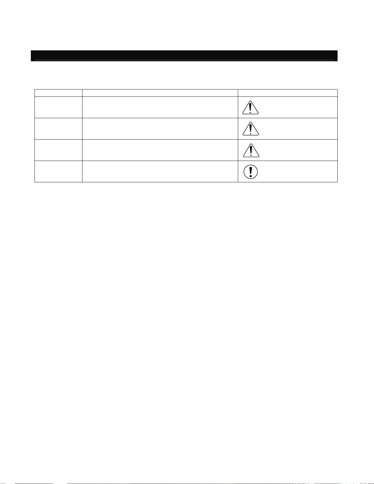
Indication of Cautionary Information
The operation manual for each model denotes safety Guides under “Danger,” “Warning,” “Caution” and “Note,” as
specified below.
Level Degree of danger/loss Symbol
Danger
Warning
Caution
Note
Failure to observe the instruction will result in an
imminent danger leading to death or serious injury.
Failure to observe the instruction may result in death or
serious injury.
Failure to observe the instruction may result in injury or
property damage.
The user should take heed of this information to ensure
the proper use of the product, although failure to do so
will not result in injury.
Danger
Warning
Caution
Note
-7-
Page 14

-8-
Page 15
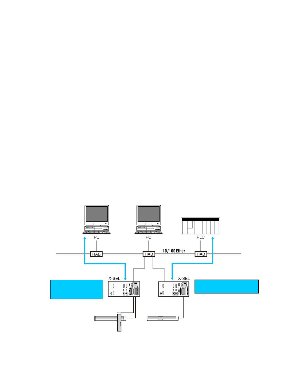
1. Overview
This option allows the X-SEL controller to perform control in an open network environment using the
Ethernet infrastructure, the de-facto standard and most common form of communication media for linking
PCs and host computers.
(1) Remote I/O control (Modbus/TCP EtherNet/IP)
The X-SEL controller supports remote I/O control (a maximum of 256 input points and 256 output
points) via Modbus/TCP.
Modbus/TCP is an Ethernet application of the Modbus protocol used in serial communicatio n.
* EtherNet/IP is supported only by X-SEL controllers of P/Q types (main application version 1.05 or
later). Also note that to use EtherNet/IP, you need an interface board compatible with EtherNet/IP.
(2) Message communication
The communication capabilities supported by the RS232C communication function of the X-SEL
controller can be implemented via Ethernet.
IAI protocol B/TCP
IAI protocol B for serial communication is supported.
The X-SEL controller can be connected to PC software.
Tra nsmission by SEL program (4 channels)
Four channels of ASCII-based, delimiter-controlled communication are supported, using a set of
transmission commands in a system roughly equivalent to that used in the X-SEL controller’s serial
communication.
Substitute programs
Send work data
(IAI protocol)
Send/receive I/O signals
(Modbus/TCP EtherNet)
- 9 -
Page 16

A hierarchy of the functions provided by the X-SEL Ethernet option is shown below.
Functions are selected by parameters. Additionally, the network environment parameters must be set.
Ethernet option
Remote I/O
Modbus/TCP
Server (slave unit)
EtherNet/IP
Adapter (equivalent to a slave)
EXCEPTION status invalid
EXCEPTION status (upper two digits of the error num ber) valid
Message communication
IAI protocol B/TCP
Client (PC software connection enabled)
Server
Transmission by SEL program (4 channels)
Client
Server
- 10 -
Page 17

2. Interface Specifications
Item Specification
Network
specification
Communication
standard
Communication
speed
Protocol
10BASE-T/100BASE-T (Auto-negotiation)
IEEE802.3
10/100 Mbps (Auto-negotiation)
Remote I/O
Open Modbus/TCP EtherNet/IP
Class 1 Read Coil
Class 1 Read Input Discretes
Class 0 Read multiple registers
Class 1 Read Input registers
Class 1 Write Coils
Class 1 Write Single register
Class 1 Read Exception status
Class 2 Force multiple Coils
Supported commands
Class 0 Force multiple registers
Class 2 Mask Write register
Class 2 Read/Write registers
Class 1
Class 3
UCMM
Cyclic
communication
Connection type
Non-connection
type
TCP/IP message
communication
1. IAI protocol B/TCP
2. Transmission by
SEL program
(4 channels)
Connector RJ-45
Cable Category 5 UTP twisted cable (see note)
(Note) Use a straight or crossed Ethernet cable according to the conne ction enviro nment.
[Normal]
Controller HUB: Straight
Controller Controller: Crossed
Controller PC: Crossed
- 11 -
Page 18
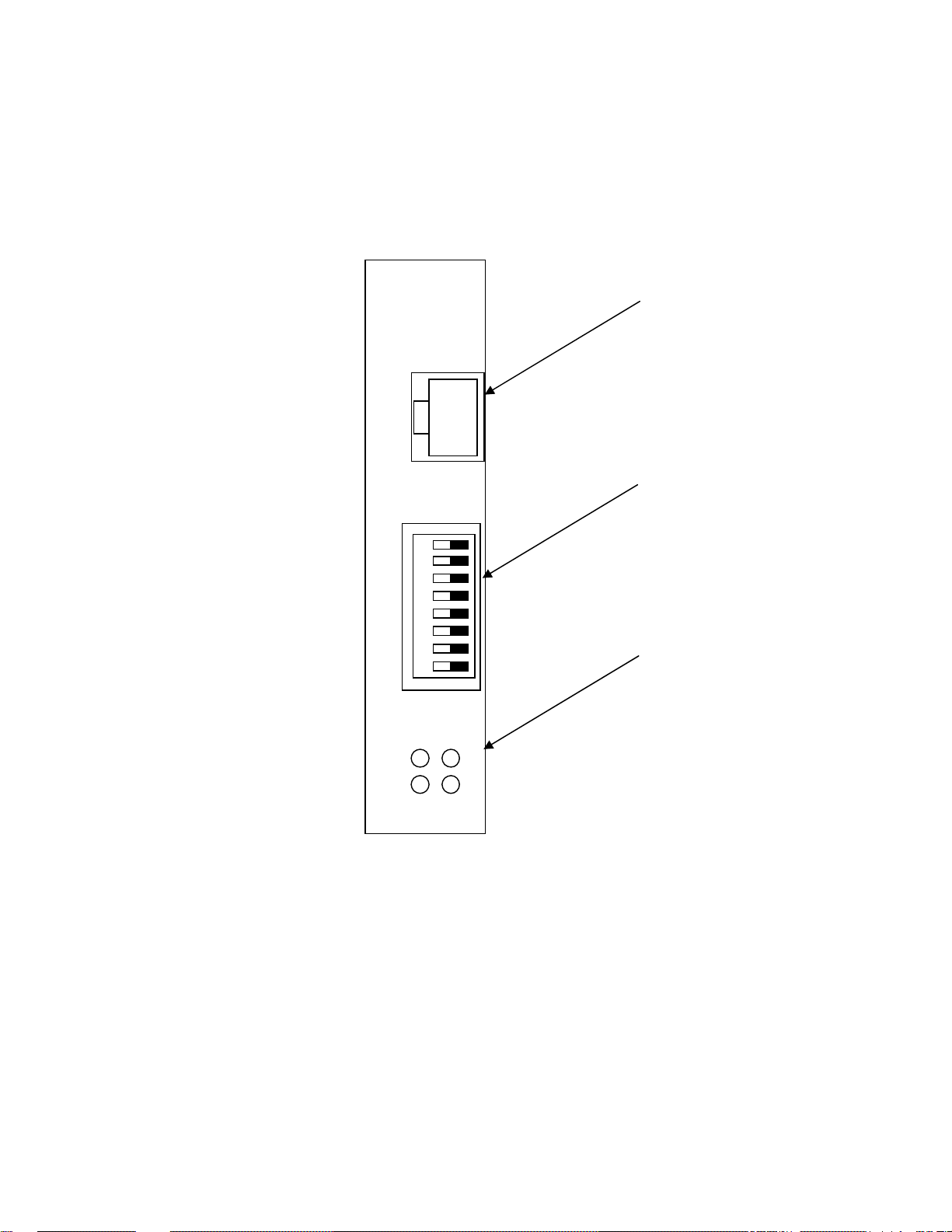
3. Interface Board
3.1 Name of Each Part
(Note) The DIP switches are used to set the least significant byte of the IP address. With
the X-SEL system, however, the IP address is set by a controller parameter without
the use of DIP switches.
Set all switches to OFF. (Setting the switches in any other pattern will have no
effect.)
S1
/S0
NS
/MS
Communication connector
DIP switches
Monitor LEDs
- 12 -
Page 19

3.2 Monitor LED Indications
The operating condition of the interface board and its connection status to Ethernet can be checked
via the four LEDs provided on the front panel of the interface board.
* The LED indications of operating condition and connection con dition vary between Modbus/TCP
and EtherNet/IP.
Modbus/TCP or TCP/IP message communication
LED Color Status Definition Explanation (factor)
Open Modbus/TCP (Remote I/O) TCP/IP Message Communication
S0
(LINK)
S1
(TRX)
MS
NS
EtherNet/IP
LED Color Status Definition Explanation (factor)
S0
(LINK)
S1
(TRX)
MS
NS
The sections in represent indications during normal operation.
- Unlit Not linked
Green Lit Linked
- Unlit No packet
Green Lit Packet detected
- Unlit No power supply
Lit Default IP
Green
Blinking at 1 Hz
Lit Duplicate IPs
Red
Blinking Catastrophic
- Unlit No Modbus/
Green Blinking Modbus/
EtherNet/IP
- Unlit Not linked
Green Lit Linked
- Unlit No packet
Green Lit Packet detected
- Unlit No power supply
Lit Normal operation
Green
Blinking Not linked
Lit Catastrophic
Red
Blinking Minor failure
- Unlit No power supply
Lit connection
Green
Blinking Connection not
Lit Catastrophic
Red
Blinking Connection
operation
Normal operation
failure
TCP connection
TCP connection
established
failure
established
established
failure
timeout
The system is not connected to Ethernet.
The system is connected to Ethernet.
TCP/IP packets are not being transmitted.
TCP/IP packets are being transmitted.
Power is not supplied to the board from the X-SEL system.
Interface board initialization is not complete.
The interface board is be ing reset.
The UTP cable is not connected.
IP address is not specified fr om the controller during operation. (As a rule, this condition should not
occur.)
The server has started normally via the controller.
Duplicate IP addresses were detected on Ethernet.
Module MAC address error (LED blinking at 1 Hz)
Network definition read error (LED blinking at 2 Hz)
Other module error (LED blinking at 4 Hz)
The Modbus/TCP connection has not been
established.
A Modbus/TCP connection has been established.
(The blinking frequency indicates the number of
connections: 1 Hz 1 connection, 2 Hz
2 connections.)
The system is not connected to Ethernet.
The system is connected to Ethernet.
TCP/IP packets are not being transmitted.
TCP/IP packets are being transmitted.
Power is not supplied to the board from the X-SEL system.
Interface board initialization is not complete.
The interface board is be ing reset.
The UTP cable is not connected.
The adapter has started normally via control by the controller.
The network is not yet established or the system is idle.
A catastrophic, irreparable failure (module error, etc.) was detected
A minor, reparable failure (duplicated IP address, etc.) was detected.
Power is not supplied to the board from the X-SEL system.
IP address is not yet set.
The system is online and connection has been established.
The system is not online and connection has not been established.
A duplicated IP address, etc., was detected.
A connection timeout was detected.
The LED will not be lit in the case of
TCP/IP message communication.
- 13 -
Page 20

4. Remote I/O (Modbus/TCP EtherNet/IP)
4.1 Setup of Ethernet Environment
The X-SEL controller provides IP addresses and other network-definition areas in its I/O parameters
for control of Modbus/TCP EtherNet/IP operation.
Set the necessary parameters according to the network environmen t before connecting to the network.
Establishing a connection without setting the parameters may disa ble normal communication to and
from other devices on the network.
* EtherNet/IP is supported only by X-SEL controllers of P/Q types (main application version 1.05 or
later). Also note that to use EtherNet/IP, you need an interface board compatible with EtherNet/IP.
[I/O parameters]
No. Parameter name Setting Input range Remarks
Ethernet operation requirement
Bits 0 to 3: Remote I/O
0: Do not use
1: Use Modbus/TCP (EXCEPTION status invalid)
129 Network attribute 10 1H 0H~FFFFFFFFH
Own MAC address (H) 0030H
130
131 Own MAC address (L) 11H
132 Own IP address (H) 192 1~255 * Setting of “0” and “127” is prohibited.
Reference value
(HEX)
Reference value
(HEX)
2: Use Modbus/TCP (EXCEPTION status valid)
3: Use EtherNet/IP (main application version 1.05 or
later)
Bits 4 to 7: TCP/IP message communication
(0: Do not use, 1: Use)
Bits 8 to 31: Not used
Only the lower two bytes are valid. (This parameter is not
settable.)
(This parameter is not settable.)
133 Own IP address (MH) 168 0~255
134 Own IP address (ML) 0 0~255
135 Own IP address (L) 1 1~254 * Setting of “0” and “255” is prohibited.
136 Subnet mask (H) 255 0~255
137 Subnet mask (MH) 255 0~255
138 Subnet mask (ML) 255 0~255
139 Subnet mask (L) 0 0~255
140 Default gateway (H) 0 0~255
141 Default gateway (MH) 0 0~255
142 Default gateway (ML) 0 0~255
143 Default gateway (L) 0 0~255
(Note) 1. Always set I/O parameter No. 129 to “1” to perform Modbus/TCP EtherNet/IP operation.
2. The Modbus/TCP port number on the controller side is fixed at “502.”
3. 44818 or 2222 is used for the EtherNet/IP port number on the controller side.
- 14 -
Page 21

4.2 Remote I/O Setup Procedure
The system is configured only with the remote I/Os of Modbus/TCP EtherNet/IP, with the I/O port
numbers being specified according to fixed port assignment.
4.2.1 Configuration with Modbus/TCP EtherNet/IP Only (No expansion I/O board)
The following settings are applicable when the system is configured only with the remote I/Os of
Modbus/TCP EtherNet/IP and the standard I/O ports are mapped on Modbus/TCP EtherNet/IP
without connections to any external devices via expansion I/O boards.
[I/O parameters]
No.
1
I/O port assignment type
Parameter name Setting Input range Remarks
0: Fixed assignment
0 0~20
I/O numbers are specified by parameters.
1: Automatic assignment (priority sequence: slot 1~)
Standard I/O input-port start
2
number (I/O1)
Standard I/O output-port start
3
number (I/O1)
Expanded I/O1 input-port start
4
number based on fixed
assignment (I/O2)
Expanded I/O1 output-port
5
start number based on fixed
assignment (I/O2)
Expanded I/O2 input-port start
6
number based on fixed
assignment (I/O3)
Expanded I/O2 output-port
7
start number based on fixed
assignment (I/O3)
Expanded I/O3 input-port start
8
number based on fixed
assignment (I/O4)
Expanded I/O3 output-port
9
start number based on fixed
assignment (I/O3)
Standard I/O error monitor
10
(I/O1)
Expanded I/O1 error monitor
11
(I/O2)
Expanded I/O2 error monitor
12
(I/O3)
Expanded I/O3 error monitor
13
(I/O4)
Number of ports using network
14
I/F-card remote input
Number of ports using network
15
I/F-card remote output
0 -1~599
300 -1~599
-1 -1~599
-1 -1~599
-1 -1~599
-1 -1~599
-1 -1~599
-1 -1~599
1 0~5
0 0~5
0 0~5
0 0~5
n 0~256
m 0~256
0 + (Multiple of 8) (A neg ative value is invalid.)
0: Assign Modbus/TCP remote DIs from No. 0.
300 + (Multiple of 8) (A negative value is invalid.)
300: Assign Modbus/TCP remote DOs from No.
300.
0 + (Multiple of 8) (A neg ative value is invalid.)
-1: No expanded I/O1 DI
300 + (Multiple of 8) (A negative value is invalid.)
-1: No expanded I/O1 DO
0 + (Multiple of 8) (A neg ative value is invalid.)
-1: No expanded I/O2 DI
300 + (Multiple of 8) (A negative value is invalid.)
-1: No expanded I/O2 DO
0 + (Multiple of 8) (A neg ative value is invalid.)
-1: No expanded I/O3 DI
300 + (Multiple of 8) (A negative value is invalid.)
-1: No expanded I/O3 DO
0: Do not monitor
1: Monitor
2: Monitor (Do not monitor 24 V I/O power error)
3: Monitor (Monitor 24 V I/O power error only)
Specify the Modbus/TCP remote DI bits by a multiple
of 8 (8 n 256).
Specify the Modbus/TCP remote DO bits by a
multiple of 8 (8 n 256).
(Note) When word registers are to be used in Modbus/TCP, set the remote I/O head numbers (I/O port start
numbers: I/O parameters 2 and 3) on a 16-bit boundary, and also set the remote I/O bits (numbers of
ports using input/output: I/O parameters 14 and 15) as a multiple of 16.
- 15 -
Page 22

4.2.2 Combined Use of Expansion I/O Board (Modbus/TCP EtherNet/IP + Expanded I/O)
The following settings are applicable when the standard I/O ports are mapped on Modbus/TCP
EtherNet/IP (input-port start No. 0 and output-port start No. 300), while the expansion I/O boards
are used with port assignments starting with input-port start No. 200 and output-port start No. 500.
[I/O parameters]
No.
1
I/O port assignment type
Standard I/O input-port start
2
number (I/O1)
Standard I/O output-port start
3
number (I/O1)
Expanded I/O1 input-port start
4
number based on fixed
assignment (I/O2)
Expanded I/O1 output-port
5
start number based on fixed
assignment (I/O2)
Expanded I/O2 input-port start
6
number based on fixed
assignment (I/O3)
Expanded I/O2 output-port
7
start number based on fixed
assignment (I/O3)
Expanded I/O3 input-port start
8
number based on fixed
assignment (I/O4)
Expanded I/O3 output-port
9
start number based on fixed
assignment (I/O3)
Standard I/O error monitor
10
(I/O1)
Expanded I/O1 error monitor
11
(I/O2)
Expanded I/O2 error monitor
12
(I/O3)
Expanded I/O3 error monitor
13
(I/O4)
Number of ports using network
14
I/F-card remote input
Number of ports using network
15
I/F-card remote output
(Note) 1. Set the parameters so that the total number of DIs and that of DOs, respectively, will not exceed 300.
2. The last DI number should be 299 or below, while the last DO number should be 599 or below.
3. When word registers are to be used in Modbus/TCP, set the remote I/O head numbers (I/O port start
Parameter name Setting Input range Remarks
0: Fixed assignment
0 0~20
I/O numbers are specified by parameters.
1: Automatic assignment (priority sequence: slot 1~)
0 -1~599
0 + (Multiple of 8) (A neg ative value is invalid.)
0: Assign Modbus/TCP remote DIs from No. 0.
300 + (Multiple of 8) (A negative value is invalid.)
300 -1~599
300: Assign Modbus/TCP remote DOs from No.
300.
0 + (Multiple of 8) (A neg ative value is invalid.)
200 -1~599
Assign DIs of expanded I/O1 from No. 200.
0 + (Multiple of 8) (A neg ative value is invalid.)
500
-1 -1~599
-1 -1~599
-1 -1~599
-1 -1~599
1 0~5
1
0 0~5
0 0~5
n 0~256
m 0~256
-1~599
0~5
Assign DOs of expanded I/O1 from No. 500.
0 + (Multiple of 8) (A neg ative value is invalid.)
-1: No expanded I/O2 DI
300 + (Multiple of 8) (A negative value is invalid.)
-1: No expanded I/O2 DO
0 + (Multiple of 8) (A neg ative value is invalid.)
-1: No expanded I/O3 DI
300 + (Multiple of 8) (A negative value is invalid.)
-1: No expanded I/O3 DO
0: Do not monitor
1: Monitor
2: Monitor (Do not monitor 24 V I/O power error)
3: Monitor (Monitor 24 V I/O power error only)
Specify the Modbus/TCP remote DI bit s by a multiple
of 8 (8 n 256).
Specify the Modbus/TCP remote DO bits by a
multiple of 8 (8 n 256).
numbers: I/O parameters 2 and 3) on a 16-bit boundary, and also set the remote I/O bits (numbers of
ports using input/output: I/O parameters 14 and 15) as a multiple of 16.
- 16 -
Page 23

4.3 Setup Procedure for Exception Status Support
The X-SEL Ethernet option supports the function that notifies the host of an error condition (the upper
two digits of the error number) of the X-SEL controller using an ex ception code store d in Modbus/T CP.
By setting bits 0 to 3 of I/O parameter No. 129 to “2” (HEX), any error occurring in the X-SEL controller
can be indicated to the host controller via Modbus/TCP.
The EXCEPTION status stores the upper two digits (one byte) of the system error number (consisting
of three digits). When this EXCEPTION status is used, provide measures a ppropriate for the error
level by referring to the descriptions in the “Error Level Control” section of the operation manual for the
X-SEL controller.
(Note) The system error number cannot be specified from the EXCEPTION status (two digits). (This
is because the error number consists of three digits.)
- 17 -
Page 24

4.4 Correspondence of Modbus/TCP Address and X-SEL I/O
Modbus/TCP can address the same object using either bit addressing or word addre ssing.
The DI area (bit numbers from No. 0 up to No. 299 can be defined) of the X-SEL controller is mapped
in the word address 0x400 (1024) (coil and holding register as viewed from the PC side) un der
Modbus/TCP.
The DO area (bit numbers from No. 300 up to No. 599 can be defined) of the X-SEL controller is
mapped in the word address 0x000 (0) (input discrete and input register as viewed from the PC side)
under Modbus/TCP.
Since the DI addressing in the X-SEL controller and the addressin g via Modbu s are different, it is
important to note the following two points:
1. The number order of one byte in the byte boundary is reversed.
(Example)
X-SEL DI7 Modbus bit address 1 (Modbus/TCP bit address 0)
DI0 Modbus bit address 8 (Modbus/TCP bit address 7)
2. When register access is executed from the X-SEL controller using an IN, INB, OUT or OUTB
command, the upper and lower bytes will be reversed.
(Example)
Writing 0x1234 to 16 bits from X-SEL DO300
Modbus input register 0 (Modbus/TCP bit address 0)
DI0 Modbus bit address 8 (Modbus/TCP bit address 7)
Both the Motorola and Intel formats can be supported using an FMIO command. (Refer to Chapter 2,
“Explanation of Commands,” in the operation manual for the X-SEL controller.) The FMIO command
changes the endian in IN/OUT commands. Executin g input or output after an FMIO command
execution with the format type set to “1” will align the byte order with Modbus/TCP. Each FMIO
command is valid only with respect to the task for which the command is executed.
A table of correspondence is shown on the next page.
- 18 -
Page 25

4.4.1 Little Endian Operation
The default endian mode of DI/DO operation commands of the X-SEL controller is the little endian.
In the little endian mode, the remote I/O field accessed via word operation with an IN, INB, OUT or
OUTB command of the X-SEL controller will have its upper and lower bytes reversed in relation to
the X-SEL data if the same field is word-accessed via Modbus/TCP.
The following examples are based on 256-bit assignments from the head DO number (= 300) in
X-SEL as Modbus/TCP remote I/Os.
(Note) Remote I/Os can be defined only as consecutive numbers.
The assignable head number must satisfy: 300 + 8n (31 n 0).
The total number of assignable bits must satisfy: m + n < 32 & 32 m, where m represents
the number of assigned remote I/O bytes.
[Modbus/TCP input areas (assignment of X-SEL DO area 300 onward)]
Address
BIT7
(MSB)
6 5 4 3 2 1
X-SEL DO 307 306 305 304 303 302 301 300
Modbus/TCP bit address 0 1 2 3 4 5 6 7
Modbus/TCP word address 0 Lower byte
Modbus input status 10001 10002 10003 10004 10005 10006 10007 10008
Modbus input register 30001 Lower byte
X-SEL DO 315 314 313 314 315 310 309 308
Modbus/TCP bit address 8 9 10 11 12 13 14 15
Modbus/TCP word address 0 Upper byte
Modbus input status 10009 10010 10011 10012 10013 10014 10015 10016
Modbus input register 30001 Upper byte
:
:
X-SEL DO 547 546 545 544 543 542 541 540
Modbus/TCP bit address 240 241 242 243 244 245 246 247
Modbus/TCP word address 15 Lower byte
Modbus input status 10248 10249 10250 10251 10252 10253 10254 10255
Modbus input register 30016 Lower byte
X-SEL DO 555 554 553 552 551 550 549 548
Modbus/TCP bit address 15 Upper byte
Modbus/TCP word address 248 249 250 251 252 253 254 255
Modbus input status 10249 10250 10251 10252 10253 10254 10255 10256
Modbus input register 30016 Upper byte
Cannot be used
Input status: input discretes single bit, provided by an I/O system, read-only
Output coil: output discretes single bit, alterable by an application program, read-write
Input register: input registers 16-bit quantity, provided by an I/O system, read-only
Output register: output registers 16-bit quantity, alterable by an application pro gram, read-write
The output areas are described on the next page.
0
(LSB)
- 19 -
Page 26

[Modbus/TCP output areas (assignment of X-SEL DI area 300 onward), FMIO = 0]
Address
X-SEL DI 7 6 5 4 3 2 1 0
Modbus/TCP bit address 16384 16385 16386 16387 16388 16389 16390 16391
Modbus/TCP word address 1024 Lower byte
Modbus output coil 1 2 3 4 5 6 7 8
Modbus hold register 40001 Lower byte
X-SEL DI 15 14 13 14 15 10 9 8
Modbus/TCP bit address 16392 16393 16394 16395 16396 16397 16398 16399
Modbus/TCP word address 1024 Upper byte
Modbus output coil 9 10 11 12 13 14 15 16
Modbus hold register 40001 Upper byte
:
:
X-SEL DI 247 246 245 244 243 242 241 240
Modbus/TCP bit address 16624 16625 16626 16627 16628 16629 16630 16631
Modbus/TCP word address 1039 Lower byte
Modbus output coil 241 242 243 244 245 246 247 248
Modbus hold register 40016 Lower byte
X-SEL DI 255 254 253 252 251 250 249 248
Modbus/TCP bit address 16632 16633 16634 16635 16636 16637 16638 16639
Modbus/TCP word address 1039 Upper byte
Modbus output coil 249 250 251 252 253 254 255 256
Modbus hold register 40016 Upper byte
BIT7
(MSB)
6 5 4 3 2 1
(LSB)
Cannot be used
0
- 20 -
Page 27

4.4.2 Big Endian Operation
To align the word handling between Modbus/TCP and the X-SEL controller, the I/O operation mode
must be set to the big endian with an FMIO command before executing a DI/DO operation
command in any X-SEL ta sk.
With this setting the remote I/O field accessed via word operation with an IN, INB, OUT or OUTB
command of the X-SEL controller can be handl ed as the same data when the same field is
word-accessed via Modbus/TCP.
The following examples are based on 256-bit assignments from the head DO number (= 300) in
X-SEL as Modbus/TCP remote I/Os.
The only difference from the examples shown in 4.4.1, “Little Endian Operation,” is the byte order
of the word registers.
(Note) Remote I/Os can be defined only as consecutive numbers.
The assignable head number must satisfy: 300 + 8n (31 n 0).
The total number of assignable bits must satisfy: m + n < 32 & 32 m, where m represents
the number of assigned remote I/O bytes.
[Modbus/TCP input areas (assignment of X-SEL DO area 300 onward)]
Address
BIT7
(MSB)
6 5 4 3 2 1
X-SEL DO 307 306 305 304 303 302 301 300
Modbus/TCP bit address 0 1 2 3 4 5 6 7
Modbus/TCP word address 0 Upper byte
Modbus input status 10001 10002 10003 10004 10005 10006 10007 10008
Modbus input register 30001 Upper byte
X-SEL DO 315 314 313 314 315 310 309 308
Modbus/TCP bit address 8 9 10 11 12 13 14 15
Modbus/TCP word address 0 Lower byte
Modbus input status 10009 10010 10011 10012 10013 10014 10015 10016
Modbus input register 30001 Lower byte
:
:
X-SEL DO 547 546 545 544 543 542 541 540
Modbus/TCP bit address 240 241 242 243 244 245 246 247
Modbus/TCP word address 15 Upper byte
Modbus input status 10248 10249 10250 10251 10252 10253 10254 10255
Modbus input register 30016 Upper byte
X-SEL DO 555 554 553 552 551 550 549 548
Modbus/TCP bit address 15 Lower byte
Modbus/TCP word address 248 249 250 251 252 253 254 255
Modbus input status 10249 10250 10251 10252 10253 10254 10255 10256
Modbus input register 30016 Lower byte
Cannot be used
Input status: input discretes single bit, provided by an I/O system, read-only
Output coil: output discretes single bit, alterable by an application program, read-write
Input register: input registers 16-bit quantity, provided by an I/O system, read-only
Output register: output registers 16-bit quantity, alterable by an application pro gram, read-write
The output areas are described on the next page.
0
(LSB)
- 21 -
Page 28

[Modbus/TCP output areas (assignment of X-SEL DI area 300 onward), FMIO = 0]
Address
X-SEL DI 7 6 5 4 3 2 1 0
Modbus/TCP bit address 16384 16385 16386 16387 16388 16389 16390 16391
Modbus/TCP word address 1024 Upper byte
Modbus output coil 1 2 3 4 5 6 7 8
Modbus hold register 40001 Upper byte
X-SEL DI 15 14 13 14 15 10 9 8
Modbus/TCP bit address 16392 16393 16394 16395 16396 16397 16398 16399
Modbus/TCP word address 1024 Lower byte
Modbus output coil 9 10 11 12 13 14 15 16
Modbus hold register 40001 Lower byte
:
:
X-SEL DI 247 246 245 244 243 242 241 240
Modbus/TCP bit address 16624 16625 16626 16627 16628 16629 16630 16631
Modbus/TCP word address 1039 Upper byte
Modbus output coil 241 242 243 244 245 246 247 248
Modbus hold register 40016 Upper byte
X-SEL DI 255 254 253 252 251 250 249 248
Modbus/TCP bit address 16632 16633 16634 16635 16636 16637 16638 16639
Modbus/TCP word address 1039 Lower byte
Modbus output coil 249 250 251 252 253 254 255 256
Modbus hold register 40016 Lower byte
BIT7
(MSB)
6 5 4 3 2 1
(LSB)
Cannot be used
0
- 22 -
Page 29

4.5 Installation to a Modbus/TCP System
No special tools are required for operation of the X-SEL cont roller via Modbus/TCP on Ethernet.
Simply set the controller parameters, connect the Ethernet cable and turn on the power. The
Modbus/TCP server in the controller will be started, enabling remote I/O control.
The Ethernet port number of Modbus/TCP is fixed at “502.”
Modbus/TCP connection is esta blished by specifying IP address port 502 for the X-SEL controller via
an OPC (OLE for process control) server or other Modbus/TCP software.
To check whether the network setup of the controller is correct, use a “ping ” command (the command
for checking the status of communication on the IP level of TCP/IP using an MS-DOS prompt (or
command prompt in Windows NT/2000)) or similar command.
4.6 Installation to an EtherNet/IP System
EtherNet/IP is supported only by X-SEL controllers of P/Q types (main application version 1.05 or
later). Also note that to use EtherNet/IP, you need an interface board compatible with EtherNet/IP.
After assembling an interface board compatible with EtherNet/IP into the controller, set the controller
parameters, connect an Ethernet cable, and then turn on the power. The EtherNet/IP adapter of the
controller (equivalent to a slave) will start and the controller will be able to perform remote I/O control.
EtherNet/IP uses Ethernet port numbers 44818 and 2222.
You can establish EtherNet/IP connection by specifying the 44818 port corresponding to the IP
address of the X-SEL controller using the EtherNet/IP software.
Use the Ping command (a MS-DOS Prompt command that checks if TCP/IP communication is
enabled at the IP level), etc., to check if the network settings of the controller are appropriate.
- 23 -
Page 30

5. IAI Protocol B/TCP
This protocol uses TCP packets embedded with the message format of IAI protocol B for serial
communication. The controller supports the slaves under thi s protocol, re gardless of the connection
method (client or server). (The connected device always becomes the protocol master.)
5.1 Setup of Ethernet Environment
The X-SEL controller provides IP addresses and other network-definition areas in its I/O parameters
for control of the IAI protocol B/TCP operation.
To select the IAI protocol B/TCP function:
Set “I/O parameter No. 129: Network attribute 10, bits 4 to 7” to “1: Use TCP/IP message
communication.”
Then, set “I/O parameter No. 124: Network attribute 5, bits 0 to 3 (MANU mode) or bits 4 to 7 (AUTO
mode)” to “1: Client (Assign own port number automatically)” or “3: Server (S pecify own port numbe r).”
Set the necessary parameters according to the network environmen t before connecting to the network.
Establishing a connection without setting the parameters may disa ble normal communication to and
from other devices on the network.
- 24 -
Page 31

[I/O parameters]
No. Parameter name Setting Input range Remarks
124
Network attribute 5 (MANU
0H~FFFFFFFFH
mode)
1H or
3H
(AUTO
mode)
10H or
30H
Ethernet TCP/IP message communication attribute
Ethernet client/server type
0: Do not use
1: Client (Assign own port number automatically)
(2: Client (Specify own port number)
This setting is not recommended in view of
the associated device restrictions, such as a
forced-error detection if the port is opened
for approximately 10 minutes in a condition
where a close response cannot be confirmed
due to a power failure in the connected
device, etc.)
3: Server (Specify own port number)
* Note: Number of clients that can be
connected to one server-port channel
simultaneously = 1
Bits 0 to 3: IAI protocol B/TCP (MANU mode)
* PC software connection is enabled in the client
mode only.
Bits 4 to 7: IAI protocol B/TCP (AUTO mode)
* PC software connection is enabled in the client
mode only.
Bits 8 to 11: User-open channel 31
Bits 12 to 15: User-open channel 32
Bits 16 to 19: User-open channel 33
Bits 20 to 23: User-open channel 34
* IAI protocol B/TCP MANU/AUTO
The connection will be cut off briefly during
switching between the MANU and AUTO modes, if
the parameter settings of “own port number,”
“client/server type,” “IP address of connection
destination” and “port number of connection
destination” do not fully correspond between the
two modes.
…
…
…
…
…
Ethernet operation requirement
Bits 0 to 3: Remote I/O
0: Do not use
1: Use Modbus/TCP (EXCEPTION status
invalid)
129
Network attribute 10 10H 0H~FFFFFFFFH
2: Use Modbus/TCP (EXCEPTION status valid)
3: Use EtherNet/ IP (main application version
1.05 or later)
Bits 4 to 7: TCP/IP message communication
0: Do not use
1: Use
Bits 8 to 31: Not used
130
Own MAC address (H) 0030H
131
Own MAC address (L) 11H
132
Own IP address (H) 192 1~255 * Setting of “0” and “127” is prohibited.
133
Own IP address (MH) 168 0~255
134
Own IP address (ML) 0 0~255
135
Own IP address (L) 1 1~254 * Setting of “0” and “255” is prohibited.
136
Subnet mask (H) 255 0~255
137
Subnet mask (MH) 255 0~255
Reference value
(HEX)
Reference value
(HEX)
Only the lower two bytes are valid. (This parameter is
not settable.)
(This parameter is not settable.)
- 25 -
Page 32

138
Subnet mask (ML) 255 0~255
139
Subnet mask (L) 0 0~255
140
Default gateway (H) 0 0~255
141
Default gateway (MH) 0 0~255
142
Default gateway (ML) 0 0~255
143
Default gateway (L) 0 0~255
…
…
…
…
…
IAI protocol B/TCP: IP
address of connection
149
destination (MANU mode)
192 1~255 * Setting of “0” and “127” is prohibited.
(H)
IAI protocol B/TCP: IP
address of connection
150
destination (MANU mode)
168 0~255
(MH)
IAI protocol B/TCP: IP
address of connection
151
destination (MANU mode)
0 0~255
(ML)
IAI protocol B/TCP: IP
address of connection
152
destination (MANU mode)
100 1~254 * Setting of “0” and “255” is prohibited.
(L)
Mode setting in parameter No. 124:
IAI protocol B/TCP: Port
153
number of connection
destination (MANU mode)
64611 0~65535
* In the server mode “0” can be set.
0 = Ignore port number of connection destination
(Only the IP address is checked.)
* In the client mode “0” cannot be set.
IAI protocol B/TCP: IP
address of connection
154
destination (AUTO mode)
192 1~255 * Setting of “0” and “127” is prohibited.
(H)
IAI protocol B/TCP: IP
address of connection
155
destination (AUTO mode)
168 0~255
(MH)
IAI protocol B/TCP: IP
address of connection
156
destination (AUTO mode)
0 0~255
(ML)
IAI protocol B/TCP: IP
address of connection
157
destination (AUTO mode)
100 1~254
* Setting of “0” and “255” is prohibited.
(L)
Mode setting in parameter No. 124:
IAI protocol B/TCP: Port
158
number of connection
destination (AUTO mode)
64611 0~65535
* In the server mode “0” can be set.
0 = Ignore port number of connection destination
(Only the IP address is checked.)
* In the client mode “0” cannot be set.
(Note) 1. To connect the controller to IAI’s PC software, set the parameter to “1: Client (Assign own port number
automatically.”
2. IAI’s PC software will detect “Error No. ECF: Socket error (PC)” if the controller-side port is disabled due to
a mode change on the controller side, reception of an IAI protocol serial-communication message or other
reason while the controller is connected to the PC software. This does not indicate abnormal status.
3. The connection will be cut off briefly during switching between the MANU and AUTO modes under IAI
protocol B/TCP, if the parameter settings of “own port number,” “client/server type,” “IP address of
connection destination” and “port number of connection destination” do not fully correspond between the
two modes.
- 26 -
Page 33

4. One of the two ports will be used for connection, depending on the MANU/AUTO mode.
5. The port will be enabled at the following intervals:
When the initialization after power ON reset is complete
When no IAI protocol serial-communication message has been received for approximately five
seconds after the completion of controller initialization
6. The port will be disabled at the following intervals:
Upon reception of an IAI protocol serial-communication message (serial communication having
priority. If the PC software is connected via serial communication, Ethernet connection will be cut
off.)
Upon mode change
Upon software reset
7. If the controller is used as a client, a connection retry will be initiated within approximately two seconds
after the recognition of a connection failure (refused, timed out, failed, etc.).
8. For details on the message format, refer to the attached “X-SEL (Cartesian/IX SCARA) Serial
Communication Specification (Format B).”
[Example of operation check procedure when the controller is used as a server]
Set the port number for the host computer and utilize the telnet tool included with your windows operating
system to communicate to the host controller. Also, set the port on the X-SEL controller side to match by
setting I/O parameter #144 (MANU mode) or No. 159 (AUTO mode). Then perform data transfer in
accordance with the format defined in the Serial Communication in order to test communication.
The following is an example of a simple check using “telnet”:
“!992001234567890@@” + Enter = Send a “test call” Receive a response, “#99200123456789034”
CR/LF is appended at the end of the sending message by “telnet.”
Using “telnet” with “Local echo enabled” will make the operation easier.
- 27 -
Page 34

5.2 Ethernet Connection of X-SEL PC Software
5.2.1 Software Versions Supporting This Function
(1) PC software V2.1.0.0 or later (Japanese version)
V2.1.0.0E or later (English version)
5.2.2 Function
(1) Connection confirmation
a. Selecting the comm unication port
Select “Ethernet” in the port name list on the Connection Confirmation screen.
* Refer to (3) of 5.2.3, “Items to Note,” for details.
Figure 1
b. Entering the own port number
Selecting “Ethernet” will change the field label “Baud Rate (bps)” to “Port No.”
Figure 2
Enter the waiting port number of the PC software in this field.
The number should match the port number specified in I/O p a rameter No. 153 (M ANU mode) o r
No. 158 (AUTO mode).
* Enter a number between 1025 and 65535 not already used in anot her application.
- 28 -
Page 35

c. Selecting the controller
Entering the port number and clicking the [OK] button switches the display to the Select
Controller screen.
Figure 3
Each time a connection is established from a controller, the IP address of the connecting
controller is added to the list. Select the IP address of the controller with which you want to
communicate, and then click the [OK] button. Communication will be established with the
selected controller and the application will start in the online mode.
Clicking the [CANCEL] button will activate the offline mode. (Even after the application is st art ed
in the offline mode, you can still switch to the online mode through “reconnecti on.”)
If the checkbox “The controller connected will be chosen automatically next time” is selected,
the application will automatically establish connection with the controller that was conn ected
first.
* Check this option only when you are communicating with a single controller or using
peer-to-peer connection.
d. Changing the connection destination
If you want to switch between multiple controllers, the connecting controller can be changed via
the following procedure.
- 29 -
Page 36

(2) Connection destination change
Select “Controller (C)” “Request Release Pause (L)” from the menu.
* This menu item will be added only when connections have been established from two or more
controllers.
Figure 4
Select the IP address of the controller with which you want to communicate, and then click the [OK]
button. Communication will be established with the selected controller.
- 30 -
Page 37

5.2.3 Items to Note
(1) When connecting via Ethernet, the IP address parameter must be set via serial
connection beforehand in accordance with the applicable environment.
(2) If a firewall (including the firewall function of virus protection software) is installed in the
PC, etc., the port block must be canceled or the firewall function disabled before a
connection can be made.
(This is because the very purpose of firewall software is to block external connection to
the protecting device.)
(3) Ethernet connection is enabled only when the checkbox “The connection to the CTL by
Ethernet is supported (for expansion)” (see Fig. 5), as provided on the “Setting” tab
accessed by selecting “Tools” “Environment Setup” from the menu, is selected (PC
software V2.1.0.4 or later).
Figure 5
- 31 -
Page 38

6. Transmission by SEL Program
Four channels of ASCII-based, delimiter-controlled communication (CH31 through CH34) are supported,
using a set of transmission commands in a system roughly equivalent to that used in the X-SEL controller’s
serial communication.
(The specification of each SEL command may vary slightly from the corresponding command specification
in serial communication, so exercise due caution.)
6.1 Setup of Ethernet Environment
To select the transmission function by SEL program:
Set “I/O parameter No. 129: Network attribute 10, bits 4 to 7” to “1: Use TCP/IP message
communication.”
Then, set “I/O parameter No. 124: Network attribute 5, bit s 8 to 11 (CH31), bits 12 to 15 (CH32), bits
16 to 19 (CH33) or bits 20 to 23 (CH34)” to “1: Client (Assign own
port number automatically)” or “3: Server (Specify own port
number).”
* Data transmission is performed by SEL program based on the specifications of the following items:
CH (channel) selection
IP address of connection destination
Port number
For programming details, refer to 6.2, “Ethernet Option SEL Commands.”
- 32 -
Page 39

[I/O parameters]
No.
124
129
130
131
132
Parameter name Setting Input range Remarks
Network attribute 5
…
Network attribute 10
Own MAC address (H)
Own MAC address (L)
Own IP address (H)
…
00***100H
(Channel 31)
00**1*00H
(Channel 32)
00*1**00H
(Channel 33)
001***00H
(Channel 34)
Or,
00***300H
(Channel 31)
00**3*00H
(Channel 32)
00*3**00H
(Channel 33)
003***00H
(Channel 34)
0H~FFFFFFFFH
…
10H 0H~FFFFFFFFH
0030H
11H
192 1~255
Reference value
Reference value
…
(HEX)
(HEX)
Ethernet TCP/IP message communication attribute
Ethernet client/server type
0: Do not use
1: Client (Assign own port number automatically)
(2: Client (Specify own port number)
This setting is not recommended in view of
the associated device restrictions, such as a
forced-error detection if the port is opened
for approximately 10 minutes in a condition
where a close response cannot be confirmed
due to a power failure in the connected
device, etc.)
3: Server (Specify own port number)
* Note: Number of clients that can be
connected to one server-port channel
simultaneously = 1
Bits 0 to 3: IAI protocol B/TCP (MANU mode)
* PC software connection is enabled in the client
mode only.
Bits 4 to 7: IAI protocol B/TCP (AUTO mode)
* PC software connection is enabled in the client
mode only.
Bits 8 to 11: User-open channel 31
Bits 12 to 15: User-open channel 32
Bits 16 to 19: User-open channel 33
Bits 20 to 23: User-open channel 34
* IAI protocol B/TCP MANU/AUTO
The connection will be cut off briefly during
switching between the MANU and AUTO modes, if
the parameter settings of “own port number,”
“client/server type,” “IP address of connection
destination” and “port number of connection
destination” do not fully correspond between the
two modes.
…
Ethernet operation requirement
Bits 0 to 3: Remote I/O
0: Do not use
1: Use Modbus/TCP (EXCEPTION status
invalid)
2: Use Modbus/TCP (EXCEPTION status valid)
3: Use EtherNet/ IP (main application version
1.05 or later)
Bits 4 to 7: TCP/IP message communication
0: Do not use
1: Use
Bits 8 to 31: Not used
Only the lower two bytes are valid. (This parameter
is not settable.)
(This parameter is not settable.)
* Setting of “0” and “127” is prohibited.
133
Own IP address (MH)
168 0~255
- 33 -
Page 40

134
Own IP address (ML)
0 0~255
135
Own IP address (L)
136
Subnet mask (H) 255 0~255
137
Subnet mask (MH) 255 0~255
138
Subnet mask (ML) 255 0~255
139
Subnet mask (L) 0 0~255
140
Default gateway (H) 0 0~255
141
Default gateway (MH) 0 0~255
142
Default gateway (ML) 0 0~255
143
Default gateway (L) 0 0~255
1 1~254
* Setting of “0” and “255” is prohibited.
- 34 -
Page 41

6.2 Ethernet Option SEL Commands
OPEN (Channel open) [* When the Ethernet option is used]
[Function] Open the channel specified in operand 1.
(Note 1) Channel Nos. 31 through 34 can be specified in operand 1 with the Ethernet option.
Up to four channels can be opened simultaneously.
(Note 2) Be sure to design the program in such a way that the normal completion or abnormal completion
(Note 3) T o change the connection destination, the channel must be closed once using a CLOS command.
Executing an OPEN command for a given channel while the channel is already open will
(Note 4) To avoid occurrence of system trouble, it is recommended that the system be built by ensuring a
(Note 5) When the controller is used as a server, the number of clients that can be connected to one
(Note 6) If a firewall (including the firewall function of virus protection software) is installed in the PC, etc.,
(This is because the very purpose of firewall software is to block external connection to the
(Note 7) The client/server mode is determined upon reset via “I/O parameter No. 124: Network attrib ute 5,
* The “Ethernet Option SEL Commands” are supported in the following versions:
X-SEL (Cartesian) Main Application V0.79 or later
X-SEL (IX SCARA) Main Application V0.29 or later
X-SEL PC Software Ver. 2.1.1.0 or later
Extension
condition
(LD, A, O, AB, OB)
Input condition
(I/O, flag)
Command,
declaration
Optional Optional OPEN
Command, declaration
Operand 1 Operand 2
Channel
number
Transmission via the specified channel will hereafter be enabled.
Before executing this command, the end character must be set with an SCHA command and the
IP address/port address of connection destinatio n with an IPCN command.
of the return code will always be confirmed before moving on to the next process.
It may take approximately four seconds to reopen the closed channel.
generate a “B1B: Ethernet socket open-without-close error.”
sufficient period so that the port opening order of the connected device and controller will satisfy
“server port open client port open.”
(1) Server open
Opens the port and waits for a
connection request from the client
(specified with an IPCN command).
(HOST A)
OPEN 33
Connection request
(2) Client open
Opens the port and issues a connection
request to the server (specified with an
IPCN command).
(HOST B)
OPEN 31
server-port channel simultaneously is 1.
the port block must be canceled or the firewall function disabled before a connection can be
made.
protecting device.)
bits 8 to 11 (CH31), bits 12 to 15 (CH32), bits 16 to 19 (CH33) or bits 20 to 23 (CH34).” The
controller cannot be used during dynamic switching between the client and server modes.
Output
(Output, flag)
Prohibited CC
- 35 -
Page 42

(Note 8) The diagram below explains the mechanism of “socket interface.”
* Bear in mind that “socket,” “connect,” “write,” “read,” “close,” “bind,” “listen” and “accept” are not
SEL language commands (SEL commands).
(1) Client open
(OPEN command)
socket
connect
Error?
N
write
read
close
Y
Generation of socket
Establishment of connection
Decide whether to
close
Data transmission
End of socket communication
execute retry or perform
error handling in
accordance with the
system.
(2) Server open
(OPEN command)
socket
bind
listen
accept
Error?
N
read
write
close
Y
Generation of socket
Waiting for connection request
Acceptance of connection
Decide whether to
close
Data transmission
End of socket communication
execute retry or perform
error handling in
accordance with the
system.
Error handling
Retry
Error handling
- 36 -
Page 43

[Example]
LET 90 192 IP address of connection destination (H) = 192
LET 91 168 IP address of connection destination (M H) = 168
LET 92 72 IP address of connection destination (M L) = 72
LET 93 101 IP address of connection destination (L) = 101
LET 94 64514 Port number of connection destination = 64514
IPCN 31 90 Declare the IP address/port number storage area for the
connection destination of channel 31 = Local integer
variable between 90 and 94.
SCHA 10 Specify 10 (= LF) as the end character.
OPEN 31 990 Open channel 31.
TRAN 1 99 Store the return code in variable 1.
N 990 GOTO 15 OPEN failed Proceed to error handling or retry
process after closing.
Common return codes of OPEN, READ and WRIT commands [* When the Ethernet option is used]
The return code is stored in the local variable specified in “Other parameter No. 24.” The default setting is
variable 99.
0: Normal completion
1: Timeout
[Specification procedure of timeout value]
OPEN:
Client mode
I/O parameter No. 127: Network attribute 8, bits 0 to 7
(Use the default setting if it poses no particular problem.)
Server mode
I/O parameter No. 128: Network attribute 9, bits 0 to 15
(Use the default setting if it poses no particular problem.)
READ: TMRD command specification
WRIT: I/O parameter No. 127: Network attribute 8, bits 16 to 23
(Use the default setting if it poses no particular problem.)
2: Cancel timer (The wait status is canceled with a TIMC command.)
3, 4: (Undefined)
5: WAIT factor error (program aborting error)
(This error cannot be recognized through SEL commands.)
6: End task (program-end request, etc.)
(This error cannot be recognized through SEL commands.)
7~12: (Undefined)
- 37 -
Page 44

50~: Device error information
50 Invalid Message ID
51 Invalid Message Type
52 Invalid Command
53 Invalid Data Size
54 Invalid Frame Count
55 Invalid Frame Number
56 Invalid Offset
57 Invalid Address
58 Invalid Response
59 Flash Config Error
60~64 Invalid To Be Defined 1-7
101 Invalid IP-address or Subnet mask
102 Invalid socket type
103 No free socket
104 Invalid socket
105 Not connected
106 Command failed
107 Invalid data size
108 Invalid fragment type
109 Fragment error
110 Invalid timeout time
111 Can't send more
112~115 (reserved)
116 Command aborted
117 Too many registered objects
118 Object already registered
119 Deregistering invalid object
121 Unsupported Command
122 (reserved)
123 No timeout
124 Invalid port number
125 Duplicate port number
126 (reserved)
127 Mapping Failed
128 Reset notification unsupported
- 38 -
Page 45

CLOS (Channel close) [* When the Ethernet option is used]
Extension
condition
(LD, A, O, AB, OB)
Input condition
(I/O, flag)
Command,
declaration
Optional Optional CLOS
Command, declaration
Operand 1 Operand 2
Channel
number
Output
(Output, flag)
Prohibited CC
[Function] Close the channel specified in operand 1.
Transmission via the specified channel will hereafter be disabled.
(Note 1) Channel Nos. 31 through 34 can be specified in operand 1 with the Ethernet option.
[Example]
CLOS 31 Close channel 31.
LET 1 32 Assign 32 to variable 1.
CLOS *1 Close the content of variable 1 (channel 32).
- 39 -
Page 46

READ (Read) [* When the Ethernet option is used]
Extension
condition
(LD, A, O, AB, OB)
Input condition
(I/O, flag)
Command,
declaration
Optional Optional READ
Command, declaration
Operand 1 Operand 2
Channel
number
Column
number
Output
(Output, flag)
CC
[Function] Read a character string from the channe l spe cified in operand 1 to the column specified in
operand 2.
The reading will end upon reaching the character specified with an SCHA command.
Either a local or global column may be specified.
(Note 1) Channel Nos. 31 through 34 can be specified in operand 1 with the Ethernet option.
(Note 2) Be sure to design the program in such a way that the normal completion or abnormal completion
of the return code will always be confirmed before moving on to the next process.
[Example]
SCHA 10 Specify 10 (= LF) as the end character.
READ 31 5 991 Read a character string from channel 31 to column 5
until LF is reached.
TRAN 2 99 Store the return code in variable 2.
N 991 GOTO 16 READ failed Proceed to error handling or retry
process after closing.
Common return codes of OPEN, READ and WRIT commands [* When the Ethernet option is used]
The return code is stored in the local variable specified in “Other parameter No. 24.” The default setting is
variable 99. For details on the return code, refer to the page describing the “OPEN” command.
- 40 -
Page 47

WRIT (Write) [* When the Ethernet option is used]
Extension
condition
(LD, A, O, AB, OB)
Input condition
(I/O, flag)
Command,
declaration
Optional Optional WRIT
Command, declaration
Operand 1 Operand 2
Channel
number
Column
number
Output
(Output, flag)
CC
[Function] Write a character string from the column specified in operand 2 to the channel specified in
operand 1.
The writing will end when the character specified with an SCHA command is written.
Either a local or global column may be specified.
(Note 1) Channel Nos. 31 through 34 can be specified in operand 1 with the Ethernet option.
(Note 2) Be sure to design the program in such a way that the normal completion or abnormal completion
of the return code will always be confirmed before moving on to the next process.
[Example]
SCHA 10 Specify 10 (= LF) as the end character.
WRIT 31 5 992 Write a character string from column 5 to channel 31 until
LF is written.
TRAN 3 99 Store the return code in variable 3.
N 992 GOTO 17 WRIT failed Proceed to error handling or retry
process after closing.
Common return codes of OPEN, READ and WRIT commands [* When the Ethernet option is used]
The return code is stored in the local variable specified in “Other parameter No. 24.” The default setting is
variable 99. For details on the return code, refer to the page describing the “OPEN” command.
- 41 -
Page 48

IPCN (IP address/port number settings of connection destination) [* When the Ethernet option is used]
Extension
condition
(LD, A, O, AB, OB)
Input condition
(I/O, flag)
Command,
declaration
Optional Optional IPCN
Command, declaration
Operand 1 Operand 2
Channel
Integer variable
number
number
Output
(Output, flag)
CP
[Function] Set the storage areas of IP address/port number for the connection destination of the user-open
TCP/IP channel. The connection destination inform ation stored in the five consecutive integer
variables, beginning with the integer variable number specified in operand 2, is defined as the
connection destination of the user-open TCP/IP channel specified in operand 1.
This command must always be executed before an OPEN command.
Variable number
specified in operand 2
Variable
number
n
n + 1
n + 2
n + 3
n + 4
Variable that stores IP address of connection destination (H)
Variable that stores IP address of connection destination (MH)
Variable that stores IP address of connection destination (ML)
Variable that stores IP address of connection destination (L)
Variable that stores port number of connection destination
(Note 1) Channel Nos. 31 through 34 can be specified in operand 1 with the Ethernet option.
(Note 2) Executing this command while a channel or channels are already open will specify settings for the
next OPEN command.
[Example]
LET 90 192 IP address of connection destination (H) = 192
LET 91 168 IP address of connection destination (M H) = 168
LET 92 72 IP address of connection destination (M L) = 72
LET 93 101 IP address of connection destination (L) = 101
LET 94 64514 Port number of connection destination = 64514
IPCN 31 90 Declare the IP address/port number storage area for the
connection destination of channel 31 = Local integer
variable between 90 and 94.
In the above example, IP address 192.168.72.101 and
port number 64514 are set as the connection destination
of user-open TCP/IP channel No. 31.
- 42 -
Page 49

7. Common Items to Note (Be Sure to Read This Section.)
(1) The Ethernet option will be enabled when a reset is executed on the controller equipped with an
Ethernet interface board, following a parameter setup (Ethernet option function-selection pa rameter
and network environment parameters) by transferring the parameters to the controller and writing
them to the flash ROM, and an Ethernet cable connection.
Check the connection to the network using a “ping” command (the command for checking the status
of communication on the IP level of TCP/IP using an MS-DOS prompt (or command prompt in
Windows NT/2000)) or similar command.
* For details on the parameters, refer to “Appendix: “X-SEL (Cartesian/IX SCARA) Ethernet Option
Parameters.”
(2) Build the system by ensuring a sufficient period so that the port opening order of the connected
device and controller will satisfy “server port open client port open.”
(3) When the controller is used as a server, the number of clients that can be connected to one
server-port channel simultaneously is 1.
(4) When the controller is used as a server, if the IP address and port number of the connected device
do not match, the network status will become “connected” and then the connection will close.
When the controller is used as a server, the port number on the client side is not already known in a
system where the client’s port number is not bound (the own port number on the client side is
assigned automatically). Therefore, set the port number of connection destination to “0” (= Ignore
port number of connected device).
With this setting, the first connection from the specified IP address will be considered a valid
connection. All connections from other ports of the same IP address will be considered invalid and
rejected until the first connection is disconnected.
(5) When the controller is used as a server , no other port may not be opened (socket cannot be
generated) in the event of insufficient socket space caused by continuous external connection to the
server port.
(6) Build the system in such a way that the power will be shut off only after a disconnection process
(socket closure) is performed on the connected-device sid e whenever the powe r is to be shut of f only
to the connected device while maintaining power to the controller.
(7) The system to be connected to the controller should constantly perform a connection check via
polling, etc., and return a close response upon receipt of a closing command from the controller.
Given the lack of a close response, in some cases the controller may not be able to open the port
(generate a socket).
(8) Select a straight or crossed Ethernet cable as deemed appropriate for the connection environment.
[Normal]
Controller HUB connection
Straight
Connection between controllers Crossed
Controller PC connection
Crossed
- 43 -
Page 50

(9) If a firewall (including the firewall function of virus protection software) is inst alled in the PC, etc., the
port block must be canceled or the firewall function disabled before a conn ection can be made.
(This is because the very purpose of firewall software is to block external connection to the
protecting device.)
(10) When the Ethernet option is enabled, the system will detect a “link error” if the connection is not
made using the correct Ethernet cable. Set “I/O parameter No. 10: Standard I/O error monitor” to “0:
Do not monitor” during debugging, teaching or other operation using an SEL program where the
Ethernet cable is not connected.
With this setting, in the online mode errors will not be detected even when the Ethernet cable is
abnormal. If the system will be used in the online mode, set the above parameter to “1: Monitor” or
“2: Monitor (Do not monitor 24 V I/O power error).”
(11) The IP address of the controller itself cannot be specified as the controller’s connection destination.
(Accordingly, a communication test or other operation involving different channels of the same
controller cannot be performed.)
(12) Due to the associated device restrictions, do not set “I/O parameter No. 124: Network attribute 5” to
“2: Client (Specify own port number).”
(13) When a parameter has been changed, always transfer the setting to the controller, write it to the
flash ROM and then reset the software.
(14) If you are contacting IAI to inquire about the encountered problem, please have the following
information ready so that we can better assist in a quick recovery and prevent any recurrence of the
problem. That information is an essential part of the troubleshooting process.
a. Error list file
b. Parameter file
c. Lighting conditions of the monitor LEDs on the front panel of the Ethernet interface board
* Refer to 3.2, “Monitor LED Indications,” for details on the monitor LEDs.
d. SEL program file
e. Symbol file
f. Position data file
(15) The descriptions provided in this manual are based on the standard parameter settings.
The content of this manual is subject to change without notice for the purp ose of product
improvement.
The product names and company names mentioned in this manual are trademarks or registered
trademarks of their respective companies.
- 44 -
Page 51

Appendix: X-SEL (Cartesian/IX SCARA) Ethernet Option Parameters
[I/O parameters]
Setting requirement
A: Required (function selection)
B: Required (network environment, etc.)
C: Checked (As a rule, the default value
on the parameter list must be used.)
Modbus/
TCP
A
A
A
A
A
A
A
IAI protocol
B/TCP
Transmission by
SEL program
C C 1
C C 2
C C 3
C C 4
C C 5
C C 6
C C 7
No. Parameter name
I/O port
assignment type
Standard I/O
input-port start
number (I/O1)
Standard I/O
output-port start
number (I/O1)
Expanded I/O1
input-port start
number based on
fixed assignment
(I/O2)
Expanded I/O1
output-port start
number based on
fixed assignment
(I/O2)
Expanded I/O2
input-port start
number based on
fixed assignment
(I/O3)
Expanded I/O2
output-port start
number based on
fixed assignment
(I/O3)
Default
value
(reference)
Input range Unit Remarks
1 0~20
0 -1~599
300 -1~599
-1 -1~599
-1 -1~599
-1 -1~599
-1 -1~599
0: Fixed assignment
I/O numbers are specified by parameters.
1: Automatic assignment (priority sequence: slot 1~)
0 + (Multiple of 8) (A neg ative value is invalid.)
0: Assign Modbus/TCP remote DIs from No. 0.
300 + (Multiple of 8) (A negative value is invalid.)
300: Assign Modbus/TCP remote DOs from No. 300.
0 + (Multiple of 8) (A neg ative value is invalid.)
-1: No expanded I/O1 DI
300 + (Multiple of 8) (A negative value is invalid.)
-1: No expanded I/O1 DO
0 + (Multiple of 8) (A neg ative value is invalid.)
-1: No expanded I/O2 DI
300 + (Multiple of 8) (A negative value is invalid.)
-1: No expanded I/O2 DO
- 45 -
Page 52

Setting requirement
A: Required (function selection)
B: Required (network environment, etc.)
C: Checked (As a rule, the default value
on the parameter list must be used.)
Modbus/
TCP
A
A
A
IAI protocol
B/TCP
Transmission by
SEL program
C C 8
C C 9
C C 10
No. Parameter name
Expanded I/O3
input-port start
number based on
fixed assignment
(I/O4)
Expanded I/O3
output-port start
number based on
fixed assignment
(I/O3)
Standard I/O error
monitor (I/O1)
Default
value
(reference)
Input range Unit Remarks
-1 -1~599
-1 -1~599
1 0~5
0 + (Multiple of 8) (A neg ative value is invalid.)
-1: No expanded I/O3 DI
300 + (Multiple of 8) (A negative value is invalid.)
-1: No expanded I/O3 DO
0: Do not monitor
1: Monitor
2: Monitor (Do not monitor 24 V I/O power error)
3: Monitor (Monitor 24 V I/O power error only)
A
A
A
A
A
C C 11
C C 12
C C 13
Expanded I/O1
error monitor (I/O2)
Expanded I/O2
error monitor (I/O3)
Expanded I/O3
error monitor (I/O4)
Number of ports
14
using network
I/F-card remote
input
Number of ports
15
using network
I/F-card remote
output
1 0~5
1 0~5
1 0~5
0 0~256
0 0~256
Specify the Modbus/TCP remote DI bits by a multiple of 8
(8 n 256).
Specify the Modbus/TCP remote DO bit s by a multiple of 8
(8 n 256).
- 46 -
Page 53

Setting requirement
A: Required (function selection)
B: Required (network environment, etc.)
C: Checked (As a rule, the default value
on the parameter list must be used.)
Modbus/
TCP
IAI protocol
B/TCP
Transmission by
SEL program
C C 123
No.
Parameter
name
Network
attribute 4
Default
value
Input range Unit Remarks
(reference)
0H 0H~FFFFFFFFH
Bits 0 to 3: Ethernet TCP/IP message communication
Selection of whether or not to permit IP address 0.0.0.0 (a
specification to ignore the IP address of the connected device)
as the connection destination when the controller is used as a
server
0: Do not permit
1: Permit (This setting is not recommended
.)
* Note: Number of clients that can be connected to one
server-port channel simultaneously = 1
Ethernet TCP/IP message communication attribute
Ethernet client/server type
0: Do not use
1: Client (Assign own port number automatically)
(2: Client (Specify own port number)
This setting is not recommended in view of the
associated device restrictions, such as a forced-error
detection if the port is opened for approximately 10
minutes in a condition where a close response cannot
be confirmed due to a power failure in the connected
device, etc.)
* Note: Number of clients that can be connected to one
server-port channel simultaneously = 1
the MANU and AUTO modes, if the parameter settings of “own
port number,” “client/server type,” “IP address of connection
destination” and “port number of connection destination” do not
fully correspond between the two modes.
A A
124
Network
attribute 5
0H 0H~FFFFFFFFH
3: Server (Specify own port number)
Bits 0 to 3: IAI protocol B/TCP (MANU mode)
* PC software connection is enabled in the client mode only.
Bits 4 to 7: IAI protocol B/TCP (AUTO mode)
* PC software connection is enabled in the client mode only.
Bits 8 to 11: User-open channel 31
Bits 12 to 15: User-open channel 32
Bits 16 to 19: User-open channel 33
Bits 20 to 23: User-open channel 34
* IAI protocol B/TCP MANU/AUTO
The connection will be cut off briefly during switching between
- 47 -
Page 54

Setting requirement
A: Required (function selection)
B: Required (network environment, etc.)
C: Checked (As a rule, the default value
on the parameter list must be used.)
Modbus/
TCP
C C C 125
C C C 126
C C C 127
A A A
B B B
IAI protocol
B/TCP
C 128
130
131
Transmission by
SEL program
No.
129
132
Parameter
name
Network
attribute 6
Network
attribute 7
Network
attribute 8
Network
attribute 9
Network
attribute 10
Own MAC
address (H)
Own MAC
address (L)
Own IP
address (H)
Default
value
(reference)
1E32H 0H~FFFFFFFFH
7D007D0H 0H~FFFFFFFFH
5050214H 0H~FFFFFFFFH
0H 0H~FFFFFFFFH
0H 0H~FFFFFFFFH
0H
0H
192 1~255 * Setting of “0” and “127” is prohibited.
Input range Unit Remarks
Bits 0 to 7: Module initialization check timer value when Ethernet
is used (100 msec)
Bits 8 to 15: Module initialization check timer value when
Ethernet is not used (100 msec)
Bits 16 to 23: Increment of “PC/TP reconnection delay time upon
software reset” when Ethernet is used (sec)
Ethernet TCP/IP message communication attribute
Bits 0 to 15: Min timeout value (msec)
Bits 16 to 31: Mout timeout value (msec)
Ethernet TCP/IP message communication attribute
Bits 0 to 7: CONNECT_TIMEOUT (sec) * Changes to this
setting are prohibited.
Bits 8 to 15: Connection retry interval (sec) (IAI protocol B/TCP)
Bits 16 to 23: Send timeout value (sec)
Bits 24 to 31: IAI protocol B-SIO non-communication check timer
value (sec) (IAI protocol B/TCP connection trigger)
Ethernet TCP/IP message communication attribute
Bits 0 to 15: SEL server open timeout value (sec)
(No timeout check when “0” is set)
Ethernet operation requirement
Bits 0 to 3: Remote I/O
0: Do not use
1: Use Modbus/TCP (EXCEPTION status invalid)
2: Use Modbus/TCP (EXCEPTION status (upper two digits
of error number) valid)
3: Use EtherNet/IP (main application version 1.05 or later)
* Handle each error according to the error level by
referring to the explanation of error level in the
operation manual.
Bits 4 to 7: TCP/IP message communication
0: Do not use
1: Use
Bits 8 to 31: Not used
Only the lower two bytes are valid.
Reference only
(HEX)
Reference only
(HEX)
- 48 -
Page 55

Setting requirement
A: Required (function selection)
B: Required (network environment, etc.)
C: Checked (As a rule, the default value
on the parameter list must be used.)
Modbus/
TCP
B B B
B B B
B B B
B B B
B B B
B B B
B B B
B B B
B B B
B B B
B B B
IAI protocol
B/TCP
C 144
C 145
C 146
C 147
C 148
Transmission by
SEL program
No. Parameter name
133
134
135 Own IP address (L) 1 1~254
136 Subnet mask (H) 255 0~255
137 Subnet mask (MH) 255 0~255
138 Subnet mask (ML) 255 0~255
139 Subnet mask (L) 0 0~255
140 Default gateway (H) 0 0~255
141
142
143 Default gate way (L) 0 0~255
Own IP address
(MH)
Own IP address
(ML)
Default gateway
(MH)
Default gateway
(ML)
IAI protocol B/TCP:
Own port number
(MANU mode)
User-open channel
31 (TCP/IP): Own
port number
User-open channel
32 (TCP/IP): Own
port number
User-open channel
33 (TCP/IP): Own
port number
User-open channel
34 (TCP/IP): Own
port number
Default value
(reference)
168 0~255
0 0~255
0 0~255
0 0~255
64511 1025~65535
64512 1025~65535
64513 1025~65535
64514 1025~65535
64515 1025~65535
Input range Unit Remarks
* Setting of “0” and “255” is prohibited.
* Important note: Be sure to set a unique number for each
own port number.
(The duplication of own port numbers is permitted only in
the IAI protocol B/TCP MANU/AUTO modes.)
- 49 -
Page 56

Setting requirement
A: Required (function selection)
B: Required (network environment, etc.)
C: Checked (As a rule, the default value
on the parameter list must be used.)
Modbus/
TCP
IAI protocol
B/TCP
B
B
B
B
B
B
B
B
B
Transmission by
SEL program
No. Parameter name
IAI protocol B/TCP: IP
address of connection
149
destination
(MANU mode) (H)
IAI protocol B/TCP: IP
address of connection
150
destination
(MANU mode) (MH)
IAI protocol B/TCP: IP
address of connection
151
destination
(MANU mode) (ML)
IAI protocol B/TCP: IP
address of connection
152
destination
(MANU mode) (L)
IAI protocol B/TCP:
Port number of
153
connection destination
(MANU mode)
IAI protocol B/TCP: IP
address of connection
154
destination
(AUTO mode) (H)
IAI protocol B/TCP: IP
address of connection
155
destination
(AUTO mode) (MH)
IAI protocol B/TCP: IP
address of connection
156
destination
(AUTO mode) (ML)
IAI protocol B/TCP: IP
address of connection
157
destination
(AUTO mode) (L)
Default value
(reference)
192 0~255 * Setting of “0” and “127” is prohibited.
168 0~255
0 0~255
100 0~254 * Setting of “0” and “255” is prohibited.
64611 0~65535
192 0~255 * Setting of “0” and “127” is prohibited.
168 0~255
0 0~255
100 0~254 * Setting of “0” and “255” is prohibited.
Input range Unit Remarks
* In the server mode “0” can be set.
0 = Ignore port number of connection destination (Only
the IP address is checked.)
* In the client mode “0” cannot be set.
- 50 -
Page 57

Setting requirement
A: Required (function selection)
B: Required (network environment, etc.)
C: Checked (As a rule, the default value
on the parameter list must be used.)
Modbus/
TCP
IAI protocol
B/TCP
B
C
Transmission by
SEL program
[Other parameters]
Setting requirement
A: Required (function selection)
B: Required (network environment, etc.)
C: Checked (As a rule, the default value
on the parameter list must be used.)
Modbus/
TCP
IAI protocol
B/TCP
Transmission by
SEL program
No. Parameter name
IAI protocol B/TCP:
Port number of
158
connection destination
(AUTO mode)
IAI protocol B/TCP:
159
Own port number
(AUTO mode)
No. Parameter name
Default value
(reference)
64611 0~65535
64516 1025~65535
Default value
(reference)
Input range Unit Remarks
Input range Unit Remarks
* In the server mode “0” can be set.
0 = Ignore port number of connection destination
(Only the IP address is checked.)
* In the client mode “0” cannot be set.
* Important note: Be sure to set a unique number for each
own port number.
(The duplication of own port numbers is permitted only in
the IAI protocol B/TCP MANU/AUTO modes.)
PC/TP reconnection
C C C 6
delay time upon
software reset
11000 1~99999 msec
- 51 -
* Valid after the PC software/TP is closed and then
restarted.
Page 58

Page 59

Page 60

Catalog No.: ME0140-3A
Head Office: 2690 W. 237th Street, Torrance, CA 90505
TEL (310) 891-6015 FAX (310) 891-0815
Chicago Office: 1261 Hamilton Parkway, Itasca, IL 60143
TEL (630) 467-9900 FAX (630) 467-9912
Atlanta Office: 1220 Kennestone Circle, Suite 108, Marietta, GA 30066
TEL (678) 354-9470 FAX (678) 354-9471
website: www.intelligentactuator.com
Ober der Röth 4, D-65824 Schwalbach am Taunus, Germany
TEL 06196-88950 FAX 06196-889524
IAI (Shanghai) Co., Ltd.
SHANGHAI JIAHUA BUSINESS CENTER A8-303, 808,Hongqiao Rd. Shanghai 200030, China
TEL 021+6448-4753 FX 021-6448-3992
website: www.iai-ro bot.com
The information contained in this document is subject to change without notice for the purpose of product improvement.
Copyright 2010. Mar. IAI Corporation. All rights reserved.
 Loading...