

Page 1

X-SEL Multi-point DIO
96-point Terminal Block Unit
Operating Manual
Table of Contents
1. Overview................................................................................................................. 1
1.1 Features.............................................................................................................. 1
1.2 Unit Variations..................................................................................................... 1
2. Configuration .......................................................................................................... 2
2.1 System Configuration.......................................................................................... 2
2.2 External View of 96-point Terminal Block Unit for Multi-point DIO....................... 3
3. Specifications.......................................................................................................... 4
3.1 Unit Specifications............................................................................................... 4
3.2 Names and Functions of Parts............................................................................ 4
4. I/O Specifications.................................................................................................... 9
4.1 Input ................................................................................................................. 9
4.2 Output ............................................................................................................... 10
5. Examples of External I/O Interface ........................................................................11
Page 2

INTELLIGENT ACTUATOR
This unit connects to a multi-point DIO board for X-SEL controller type K (general-purpose type) and
divides the power supply into multiple external interface circuits. This unit cannot be used with X-SEL
controller type J (compact type).
Separate interface circuits are provided for six DI/DO groups (each group consisting of eight points). This
allows for separate wiring of interface power supplies for external I/O equipment.
1. Overview
1.1 Features
[1] Dividing the DIO interface power supply (24 VDC) into 12 groups
This unit has built-in insulated DIO interface circuits for six input groups (each group consisting of
eight points) and six output groups (each group consisting of eight points).
[2] Conversion from one half-pitch flat connector to three MIL flat connectors
A multi-point DIO connector for 48 DIs/48 DOs can be divided into three I/O connectors each
providing 16 DIs/16 DOs.
[3] Support of DO large-current output specification
This unit has a transistor buffer circuit to support an output current of 500 mA per point (0.8 A per
eight points).
[4] Support of NPN and PNP DIO interfaces
Both NPN and PNP-type DIO interfaces are supported (the supported interface specification is set
before shipment). With both the NPN and PNP units, the connected controller DIO board must be of
NPN type.
1.2 Unit Variations
Table 0-1 Variation List for 96-point Terminal Block Unit for X-SEL Multi-point DIO
Model Name Overview
IATU3204-NP1
IATU3204-PN1
96-point terminal block unit for X-SEL
multi-point DIO, NPN specification
96-point terminal block unit for X-SEL
multi-point DIO, PNP specification
A unit with large-current output
circuit (NPN)
A unit with large-current output
circuit (PNP)
1
Page 3

INTELLIGENT ACTUATOR
2. Configuration
2.1 System Configuration
Fig. 2-1 Connection Example
X-SEL general-purpose controller (type K)
Half-pitch connector
40-pin MIL connector
Input common
24 VDC
(IN00 ∼ 07)
(IN08 ∼ 15)
Input common
24 VDC
(IN16 ∼ 23)
(IN24 ∼ 31)
Model Name
Half-pitch I/O flat cable
(w/ connectors on both ends)
Output power
supply
24 VDC
(OUT00 ∼ 07)
(OUT08 ∼ 15)
CB-X-PIOH020-H6
Output power
(OUT16 ∼ 23)
(OUT24 ∼ 31)
Multi-point I/O board
DIO terminal block unit
Output power
supply
24 VDC
(OUT32 ∼ 39)
(OUT40 ∼ 47)
For connection between the controller’s
multi-point DIO board and the DIO
terminal block unit.
Connect a 24-VDC power supply
to the IO24V power-input
connector on the panel board.
Half-pitch I/O flat cable
I/O flat cables
Input common
supply
24 VDC
(IN32 ∼ 39)
(IN40 ∼ 47)
Connection
24 VDC
I/O flat cables
(w/ connector on one end)
CB-RCBC-PIO020
For connection between the DIO terminal
block unit and peripheral equipment.
2
Page 4

INTELLIGENT ACTUATOR
2.2 External View of 96-point Terminal Block Unit for Multi-point DIO
Fig. 2-2 External View
3
Page 5

INTELLIGENT ACTUATOR
3. Specifications
3.1 Unit Specifications
Table 3-1 Unit Specifications
Item Specification
Numbers of connectable I/O points 48 input points, 48 output points
Controller connector 100-pin half-pitch flat connector
External I/O equipment connector 40-pin MIL flat connector
External power-supply voltage
Installation method Installation on DIN rail
External dimensions
3.2 Names and Functions of Parts
24 VDC ± 10% (Internal consumption: 7.2 W)
Power supply for DIO board: 24 VDC ±10% (Internal
201.3 mm × 127.5 mm × 49.2 mm
consumption: 25 W (96 points))
4
Page 6
INTELLIGENT ACTUATOR
[1] Multi-point DIO connector (CN1)
This connector is used to connect a multi-point DIO board for X-SEL controller.
Table 3-2 Specification List for Multi-point DIO Connector
Item
Connector HIF6-100PA-12.7DSA (by Hirose)
100-pin half-pitch flat connector
Connector name CN1
DI 48 points
DO 48 points
Connected unit Multi-point DIO board
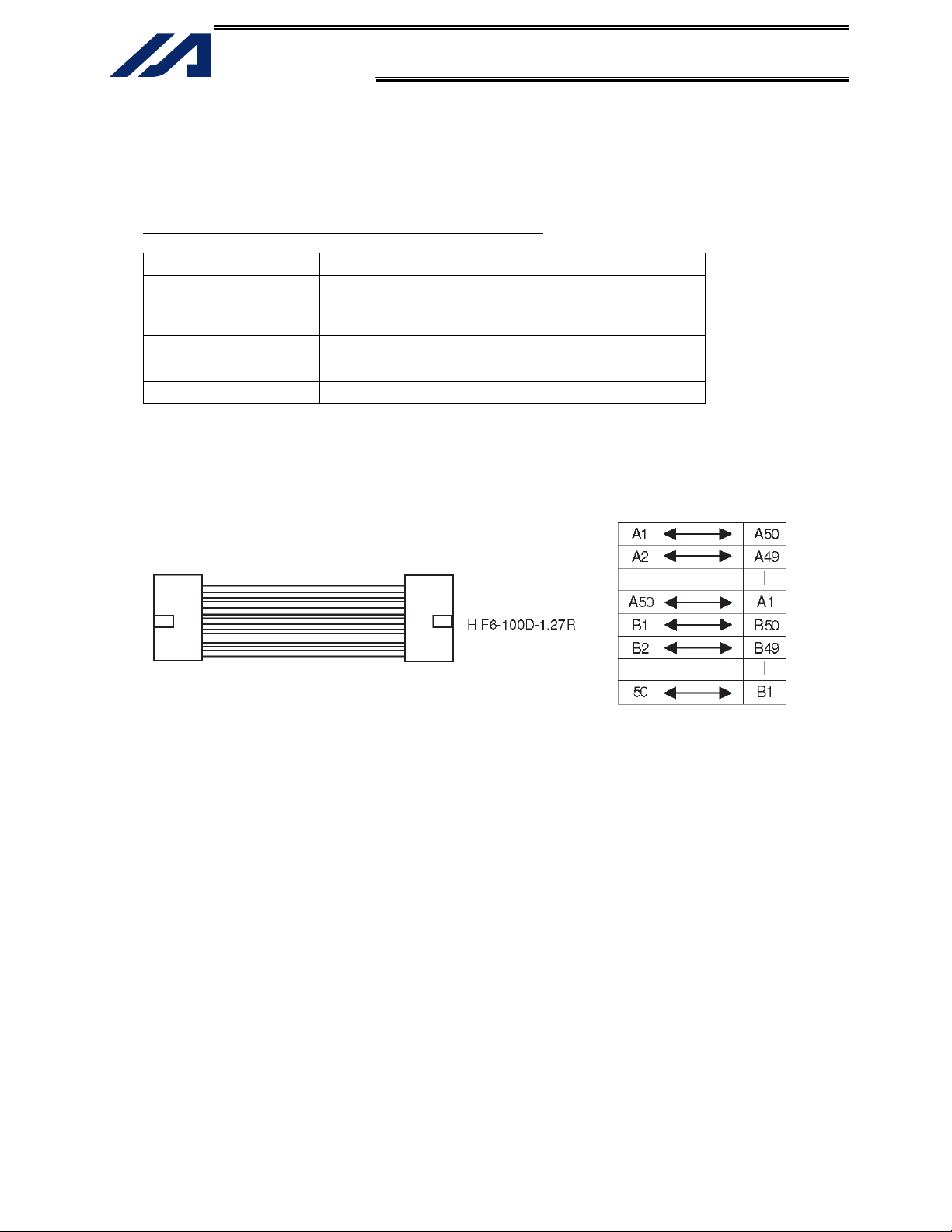
• The wiring cable used for connection with a multi-point DIO board is shown below.
Cable model: CB-X-PIOH020-H6
Multi-point DIO board end
Terminal block unit end
(on both ends)
AWG28 flat cable
B
5
Page 7

INTELLIGENT ACTUATOR
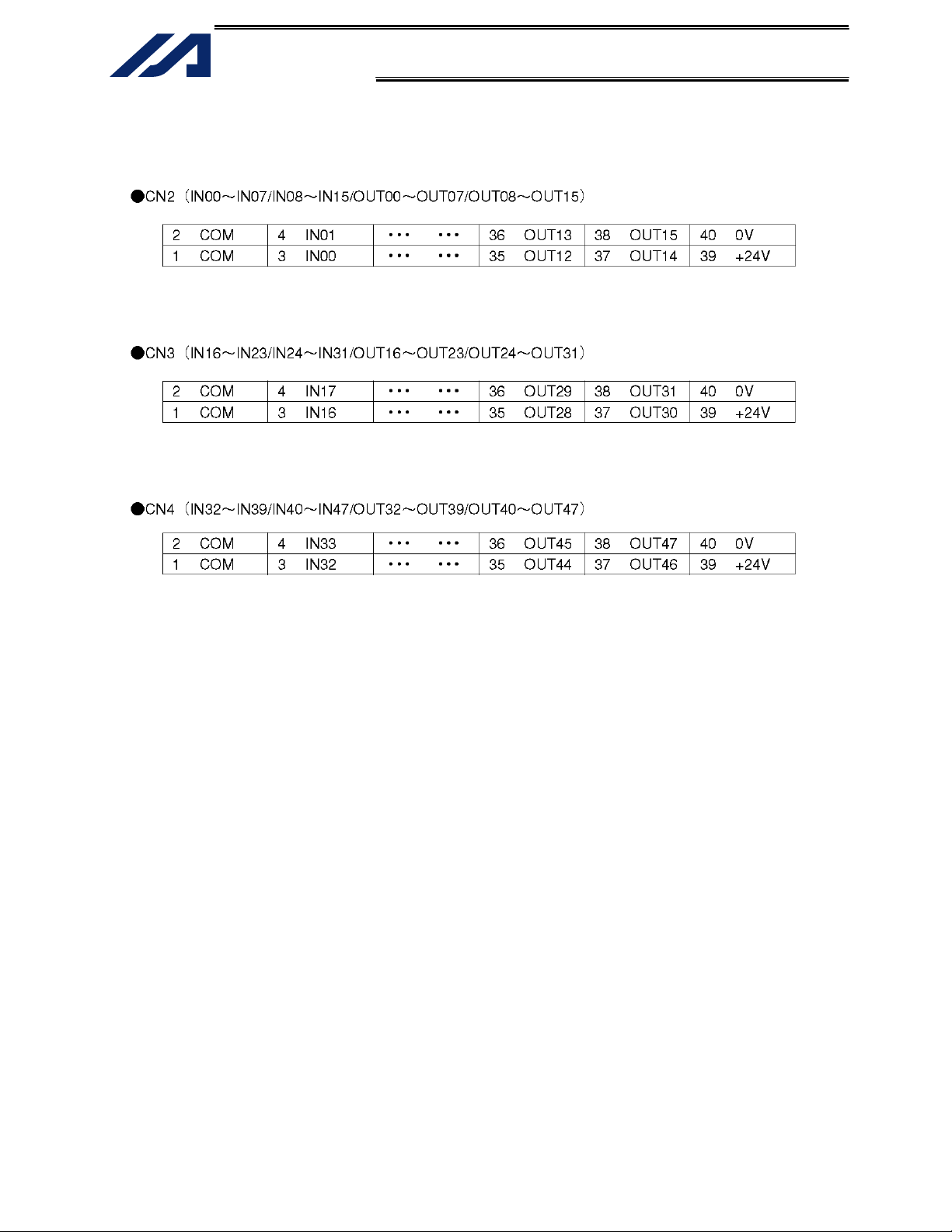
[2] External I/O connector (CN2, CN3, CN4)
This connector is used to connect external I/O equipment.
One connector accommodates 16 DIs and 16 DOs.
Table 3-3 Specification List for External I/O Connector
Item
Connector XG4A-4031 (OMRON) 40-pin MIL flat connector
DI 16 points each
DO 16 points each
Connected unit External I/O equipment
Connector name CN2 CN3 CN4
Terminal
assignments
Input
Terminal
assignments
Output
1 Common
2 Common
3 General-purpose input IN00 IN16 IN32
4 General-purpose input IN01 IN17 IN33
5 General-purpose input IN02 IN18 IN34
6 General-purpose input IN03 IN19 IN35
7 General-purpose input IN04 IN20 IN36
8 General-purpose input IN05 IN21 IN37
9 General-purpose input IN06 IN22 IN38
10 General-purpose input IN07 IN23 IN39
11 General-purpose input IN08 IN24 IN40
12 General-purpose input IN09 IN25 IN41
13 General-purpose input IN10 IN26 IN42
14 General-purpose input IN11 IN27 IN43
15 General-purpose input IN12 IN28 IN44
16 General-purpose input IN13 IN29 IN45
17 General-purpose input IN14 IN30 IN46
18 General-purpose input IN15 IN31 IN47
19 Common
20 Common
21
+24 V
22 0 V
23 General-purpose input OUT00 OUT16 OUT32
24 General-purpose input OUT01 OUT17 OUT33
25 General-purpose input OUT02 OUT18 OUT34
26 General-purpose input OUT03 OUT19 OUT35
27 General-purpose input OUT04 OUT20 OUT36
28 General-purpose input OUT05 OUT21 OUT37
29 General-purpose input OUT06 OUT22 OUT38
30 General-purpose input OUT07 OUT23 OUT39
31 General-purpose input OUT08 OUT24 OUT40
32 General-purpose input OUT09 OUT25 OUT41
33 General-purpose input OUT10 OUT26 OUT42
34 General-purpose input OUT11 OUT27 OUT43
35 General-purpose input OUT12 OUT28 OUT44
36 General-purpose input OUT13 OUT29 OUT45
37 General-purpose input OUT14 OUT30 OUT46
38 General-purpose input OUT15 OUT31 OUT47
39
+24 V
40 0 V
Common terminal
(COM):
For IN00 to IN07
Common terminal
(COM):
For IN08 to IN15
External 24-V power
input: For OUT00 to
OUT07
External 24-V power
input: For OUT08 to
OUT15
Common terminal
(COM):
For IN16 to IN23
Common terminal
(COM):
For IN24 to IN31
External 24-V power
input: For OUT16 to
OUT23
External 24-V power
input: For OUT24 to
OUT31
Common terminal
(COM):
For IN32 to IN39
Common terminal
(COM):
For IN40 to IN47
External 24-V power
input: For OUT32 to
OUT39
External 24-V power
input: For OUT40 to
OUT47
6
Page 8
Pint layout
INTELLIGENT ACTUATOR
Guide key end
Guide key end
Guide key end
7
Page 9

INTELLIGENT ACTUATOR
[3] LED indicators
This unit has LED indicators that show the DO power-input status for each connector.
If external power is not input or a fuse on the board is blown, the applicable LED will turn off.
All fuses are resettable (meaning that the fuse will reconnect automatically once an overcurrent
condition is removed). One fuse is provided for each group of eight DOs.
Table 3-4 LED Indicator Specifications
Symbol Color Applicable external power input
LED1 Green
LED2 Green
LED3 Green
LED4 Green
LED5 Green
LED6 Green
CN2 external power-input indicator
CN3 external power-input indicator
CN4 external power-input indicator
OUT00 ∼ 07
OUT08 ∼ 15
OUT16 ∼ 23
OUT24 ∼ 31
OUT32 ∼ 39
OUT40 ∼ 47
[4] External power-supply open detection switch (SW1)
This unit is capable of outputting a detection signal indicating absence of external DO power supply (24
VDC) to the X-SEL controller.
To use this function, the dedicated switch (SW1) must be set to the ON position.
In the power-supply open detection mode, IN47 becomes a dedicated input for detection signal.
The applicable X-SEL controller parameter must also be set to specify error detection input for the
terminal block unit.
I/O parameter No. 23: Specification of overcurrent/power-supply error detection input for multi-point
DIO external terminal block
Example 1) To detect power-supply open failure only for the unit connected to the multi-point I/O
board in expansion slot I/O1 (I/O2), set I/O parameter No. 23 to “20.”
Example 2) To detect power-supply open failure for both units connected to the multi-point I/O
boards in expansion slots I/O1 (I/O2) and I/O2 (I/O3), set I/O parameter No. 23 to “220.”
If you want to use IN47 as a normal general-purpose input instead of an open-failure detection signal,
be sure to set the switch to the OFF position.
8
Page 10

INTELLIGENT ACTUATOR
4. I/O Specifications
4.1 Input
Table 4-1 Specifications of Input Part
Item Specification (Common to PNP and NPN specifications)
Insulated element Photocoupler (by NEC: PS2845-4A)
External power-supply voltage
Input current Max. 7 mA/point
Leak current Max. 1 mA/point
Fig. 4-1 Circuit of Input Part
• Common to PNP and NPN specifications
Internal circuit
24 VDC ± 10%
External I/O connector
Input terminal
External power supply
(24 VDC)
9
Page 11

INTELLIGENT ACTUATOR
4.2 Output
Table 4-2 Specifications of Output Part
Output element MOS-FET (by Toshiba: 2SK2399) MOS-FET (by Toshiba: 2SJ377)
Insulated element Photocoupler (by NEC: PS2841-4B)
External power-supply voltage
24 VDC ± 10%
Maximum load current Max. 500 mA/point
(Max. 800 mA/ 8 points) : *1
Leak current Max. 0.5 mA/point
*1: The maximum load current of 800 mA indicates the total of output currents for each 8-point
group.
Fig. 4-2 Circuit of Output Part
• NPN specification
Internal circuit
• PNP specification
Internal circuit
Specification
NPN specification PNP specification
External I/O connector
+24 V
Output terminal
Load
External power supply
(24 VDC)
External I/O connector
+24 V
Output terminal
Load
External power supply
(24 VDC)
10
Page 12

INTELLIGENT ACTUATOR
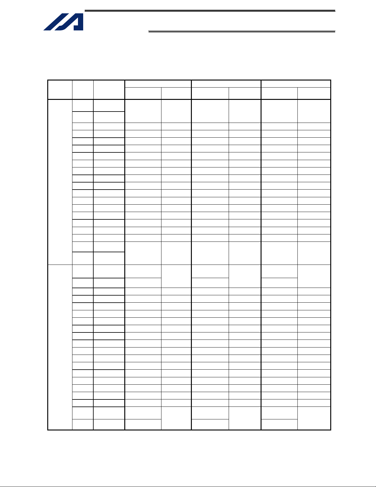
5. Examples of External I/O Interface
Example of interface list 1
The interface list below assumes that the first multi-point DIO board is installed in expansion slot 1
(I/O2). (When one multi-point DIO board is installed in addition to the standard I/O board (32 IN points,
16 OUT points))
I/O parameter No. 1 = “1” (Automatic assignment)
Category Pin No. Color
1 Brown-1
2 Red-1
3 Orange-1 032 IN00 048 IN16 064 IN32
4 Yellow-1 033 IN01 049 IN17 065 IN33
5 Green-1 034 IN02 050 IN18 066 IN34
6 Blue-1 035 IN03 051 IN19 067 IN35
7 Purple-1 036 IN04 052 IN20 068 IN36
8 Gray-1 037 IN05 053 IN21 069 IN37
9 White-1 038 IN06 054 IN22 070 IN38
Input
Output
10 Black-1 039 IN07 055 IN23 071 IN39
11 Brown-2 040 IN08 056 IN24 072 IN40
12 Red-2 041 IN09 057 IN25 073 IN41
13 Orange-2 042 IN10 058 IN26 074 IN42
14 Yellow-2 043 IN11 059 IN27 075 IN43
15 Green-2 044 IN12 060 IN28 076 IN44
16 Blue-2 045 IN13 061 IN29 077 IN45
17 Purple-2 046 IN14 062 IN30 078 IN46
18 Gray-2 047 IN15 063 IN31 079 IN47
19 White-2
20 Black-2
21 Brown-3
22 Red-3 0 V
23 Orange-3 316 OUT00 332 OUT16 348 OUT32
24 Yellow-3 317 OUT01 333 OUT17 349 OUT33
25 Green-3 318 OUT02 334 OUT18 350 OUT34
26 Blue-3 319 OUT03 335 OUT19 351 OUT35
27 Purple-3 320 OUT04 336 OUT20 352 OUT36
28 Gray-3 321 OUT05 337 OUT21 353 OUT37
29 White-3 322 OUT06 338 OUT22 354 OUT38
30 Black-3 323 OUT07 339 OUT23 355 OUT39
31 Brown-4 324 OUT08 340 OUT24 356 OUT40
32 Red-4 325 OUT09 341 OUT25 357 OUT41
33 Orange-4 326 OUT10 342 OUT26 358 OUT42
34 Yellow-4 327 OUT11 343 OUT27 359 OUT43
35 Green-4 328 OUT12 344 OUT28 360 OUT44
36 Blue-4 329 OUT13 345 OUT29 361 OUT45
37 Purple-4 330 OUT14 346 OUT30 362 OUT46
38 Gray-4 331 OUT15 347 OUT31 363 OUT47
39 White-4
40 Black-4 0 V
Port No.
Terminal name
COM terminal
COM terminal
+24 V +24 V +24 V
+24 V +24 V +24 V
CN2 CN3 CN4
Function
For inputs 032
to 039
NPN: 24 V
PNP: 0 V
For inputs 040
to 047
NPN: 24 V
PNP: 0 V
For outputs 316
to 323
External power
input
For outputs 324
to 331
External power
input
Port No.
Terminal name
COM terminal
COM terminal
0 V
0 V
Function
For inputs 048 to
055
NPN: 24 V
PNP: 0 V
For inputs 056 to
063
NPN: 24 V
PNP: 0 V
For outputs 332
to 339
External power
input
For outputs 340
to 347
External power
input
Port No.
Terminal name
COM terminal
COM terminal
0 V
0 V
Function
For inputs 064
to 071
NPN: 24 V
PNP: 0 V
For inputs 072
to 079
NPN: 24 V
PNP: 0 V
For outputs 348
to 355
External power
input
For outputs 356
to 363
External power
input
11
Page 13

INTELLIGENT ACTUATOR
Example of interface list 2
The interface list below assumes that the second multi-point DIO board is installed in expansion slot 2
(I/O3).
I/O parameter No. 1 = “1” (Automatic assignment)
Category Pin No. Color
1 Brown-1
2 Red-1
3 Orange-1 080 IN00 096 IN16 112 IN32
4 Yellow-1 081 IN01 097 IN17 113 IN33
5 Green-1 082 IN02 098 IN18 114 IN34
6 Blue-1 083 IN03 099 IN19 115 IN35
7 Purple-1 084 IN04 100 IN20 116 IN36
8 Gray-1 085 IN05 101 IN21 117 IN37
9 White-1 086 IN06 102 IN22 118 IN38
Input
Output
10 Black-1 087 IN07 103 IN23 119 IN39
11 Brown-2 088 IN08 104 IN24 120 IN40
12 Red-2 089 IN09 105 IN25 121 IN41
13 Orange-2 090 IN10 106 IN26 122 IN42
14 Yellow-2 091 IN11 107 IN27 123 IN43
15 Green-2 092 IN12 108 IN28 124 IN44
16 Blue-2 093 IN13 109 IN29 125 IN45
17 Purple-2 094 IN14 110 IN30 126 IN46
18 Gray-2 095 IN15 111 IN31 127 IN47
19 White-2
20 Black-2
21 Brown-3
22 Red-3 0 V
23 Orange-3 364 OUT00 380 OUT16 396 OUT32
24 Yellow-3 365 OUT01 381 OUT17 397 OUT33
25 Green-3 366 OUT02 382 OUT18 398 OUT34
26 Blue-3 367 OUT03 383 OUT19 399 OUT35
27 Purple-3 368 OUT04 384 OUT20 400 OUT36
28 Gray-3 369 OUT05 385 OUT21 401 OUT37
29 White-3 370 OUT06 386 OUT22 402 OUT38
30 Black-3 371 OUT07 387 OUT23 403 OUT39
31 Brown-4 372 OUT08 388 OUT24 404 OUT40
32 Red-4 373 OUT09 389 OUT25 405 OUT41
33 Orange-4 374 OUT10 390 OUT26 406 OUT42
34 Yellow-4 375 OUT11 391 OUT27 407 OUT43
35 Green-4 376 OUT12 392 OUT28 408 OUT44
36 Blue-4 377 OUT13 393 OUT29 409 OUT45
37 Purple-4 378 OUT14 394 OUT30 410 OUT46
38 Gray-4 379 OUT15 395 OUT31 411 OUT47
39 White-4
40 Black-4 0 V
Port No.
Terminal name
COM terminal
COM terminal
CN2 CN3 CN4
Function
For inputs
080 to 087
NPN: 24 V
PNP: 0 V
For inputs
088 to 095
NPN: 24 V
PNP: 0 V
+24 V +24 V +24 V
+24 V +24 V +24 V
For outputs
364 to 371
External
power input
For outputs
372 to 379
External
power input
Port No.
Terminal name
COM terminal
COM terminal
0 V
0 V
Function
For inputs
096 to 103
NPN: 24 V
PNP: 0 V
For inputs
104 to 111
NPN: 24 V
PNP: 0 V
For outputs
380 to 387
External
power input
For outputs
388 to 395
External
power input
Port No.
Terminal name
COM terminal
COM terminal
0 V
0 V
Function
For inputs
112 to 119
NPN: 24 V
PNP: 0 V
For inputs
120 to 127
NPN: 24 V
PNP: 0 V
For outputs
396 to 403
External
power input
For outputs
404 to 411
External
power input
12
Page 14
INTELLIGENT ACTUATOR
Example of interface list 3
The interface list below assumes that the third multi-point DIO board is installed in expansion slot 3
(I/O4).
I/O parameter No. 1 = “1” (Automatic assignment)
Category Pin No. Color
1 Brown-1
2 Red-1
3 Orange-1 128 IN00 144 IN16 160 IN32
4 Yellow-1 129 IN01 145 IN17 161 IN33
5 Green-1 130 IN02 146 IN18 162 IN34
6 Blue-1 131 IN03 147 IN19 163 IN35
7 Purple-1 132 IN04 148 IN20 164 IN36
8 Gray-1 133 IN05 149 IN21 165 IN37
9 White-1 134 IN06 150 IN22 166 IN38
Input
Output
10 Black-1 135 IN07 151 IN23 167 IN39
11 Brown-2 136 IN08 152 IN24 168 IN40
12 Red-2 137 IN09 153 IN25 169 IN41
13 Orange-2 138 IN10 154 IN26 170 IN42
14 Yellow-2 139 IN11 155 IN27 171 IN43
15 Green-2 140 IN12 156 IN28 172 IN44
16 Blue-2 141 IN13 157 IN29 173 IN45
17 Purple-2 142 IN14 158 IN30 174 IN46
18 Gray-2 143 IN15 159 IN31 175 IN47
19 White-2
20 Black-2
21 Brown-3
22 Red-3 0 V
23 Orange-3 412 OUT00 428 OUT16 444 OUT32
24 Yellow-3 413 OUT01 429 OUT17 445 OUT33
25 Green-3 414 OUT02 430 OUT18 446 OUT34
26 Blue-3 415 OUT03 431 OUT19 447 OUT35
27 Purple-3 416 OUT04 432 OUT20 448 OUT36
28 Gray-3 417 OUT05 433 OUT21 449 OUT37
29 White-3 418 OUT06 434 OUT22 450 OUT38
30 Black-3 419 OUT07 435 OUT23 451 OUT39
31 Brown-4 420 OUT08 436 OUT24 452 OUT40
32 Red-4 421 OUT09 437 OUT25 453 OUT41
33 Orange-4 422 OUT10 438 OUT26 454 OUT42
34 Yellow-4 423 OUT11 439 OUT27 455 OUT43
35 Green-4 424 OUT12 440 OUT28 456 OUT44
36 Blue-4 425 OUT13 441 OUT29 457 OUT45
37 Purple-4 426 OUT14 442 OUT30 458 OUT46
38 Gray-4 427 OUT15 443 OUT31 459 OUT47
39 White-4
40 Black-4 0 V
Port No.
Terminal name
COM terminal
COM terminal
CN2 CN3 CN4
Function
For inputs
128 to 135
NPN: 24 V
PNP: 0 V
For inputs
136 to 143
NPN: 24 V
PNP: 0 V
+24 V +24 V +24 V
+24 V +24 V +24 V
For outputs
412 to 419
External
power input
For outputs
420 to 427
External
power input
Port No.
Terminal name
COM terminal
COM terminal
0 V
0 V
Function
For inputs
144 to 151
NPN: 24 V
PNP: 0 V
For inputs
152 to 159
NPN: 24 V
PNP: 0 V
For outputs
428 to 435
External
power input
For outputs
436 to 443
External
power input
Port No.
Terminal name
COM terminal
COM terminal
0 V
0 V
For inputs
160 to 167
NPN: 24 V
For inputs
168 to 175
NPN: 24 V
For outputs
444 to 451
power input
For outputs
452 to 459
power input
Function
PNP: 0 V
PNP: 0 V
External
External
13
Page 15

Manual No.: ME0139-1A (December 2011)
Head Office: 577-1 Obane Shimizu-KU Shizuoka City Shizuoka 424-0103, Japan
TEL +81-54-364-5105 FAX +81-54-364-2589
website: www.iai-robot.co.jp/
Technical Support available in USA, Europe and China
Head Office: 2690 W. 237th Street, Torrance, CA 90505
TEL (310) 891-6015 FAX (310) 891-0815
Chicago Office: 1261 Hamilton Parkway, Itasca, IL 60143
TEL (630) 467-9900 FAX (630) 467-9912
Atlanta Office: 1220 Kennestone Circle, Suite 108, Marietta, GA 30066
TEL (678) 354-9470 FAX (678) 354-9471
website: www.intelligentactuator.com
Ober der Röth 4, D-65824 Schwalbach am Taunus, Germany
TEL 06196-88950 FAX 06196-889524
SHANGHAI JIAHUA BUSINESS CENTER A8-303, 808, Hongqiao Rd. Shanghai 200030, China
TEL 021-6448-4753 FAX 021-6448-3992
website: www.iai-robot.com
The information contained in this document is subject to change without notice for purposes of
product improvement.
Copyright © 2011. Dec. IAI Corporation. All rights reserved.
11.12.000
 Loading...