

Page 1

Tabletop Robot
TT
Operation Manual 6th Edition
10th Edition
Page 2

Page 3

INTELLIGENT ACTUATOR
Please Read Before Use
Thank you for purchasing our product.
This Operation Manual explains the handling methods, structure and maintenance of this product, among others,
providing the information you need to know to use the product safely.
Before using the product, be sure to read this manual and fully understand the contents explained herein to
ensure safe use of the product.
The CD or DVD that comes with the product co ntains operation manuals for IAI products.
When using the product, refer to the necessary portions of the applicable operation manual by printing them out
or displaying them on a PC.
After reading the Operation Manual, keep it in a convenient place so that whoever is handling this product can
reference it quickly when necessary.
[Important]
This Operation Manual is original.
The product cannot be operated in any way unless expressly specified in this Operation Manual. IAI shall
assume no responsibility for the outcome of any operation not specified herein.
Information contained in this Operation Manual is subject to change without notice for the purpose of
product improvement.
If you have any question or comment regarding the content of this manual, please contact the IAI sales
office near you.
Using or copying all or part of this Operation Manual without permission is prohibited.
The company names, names of products and trademarks of each company shown in the sentences are
registered trademarks.
Page 4
1. Notes on operation
m
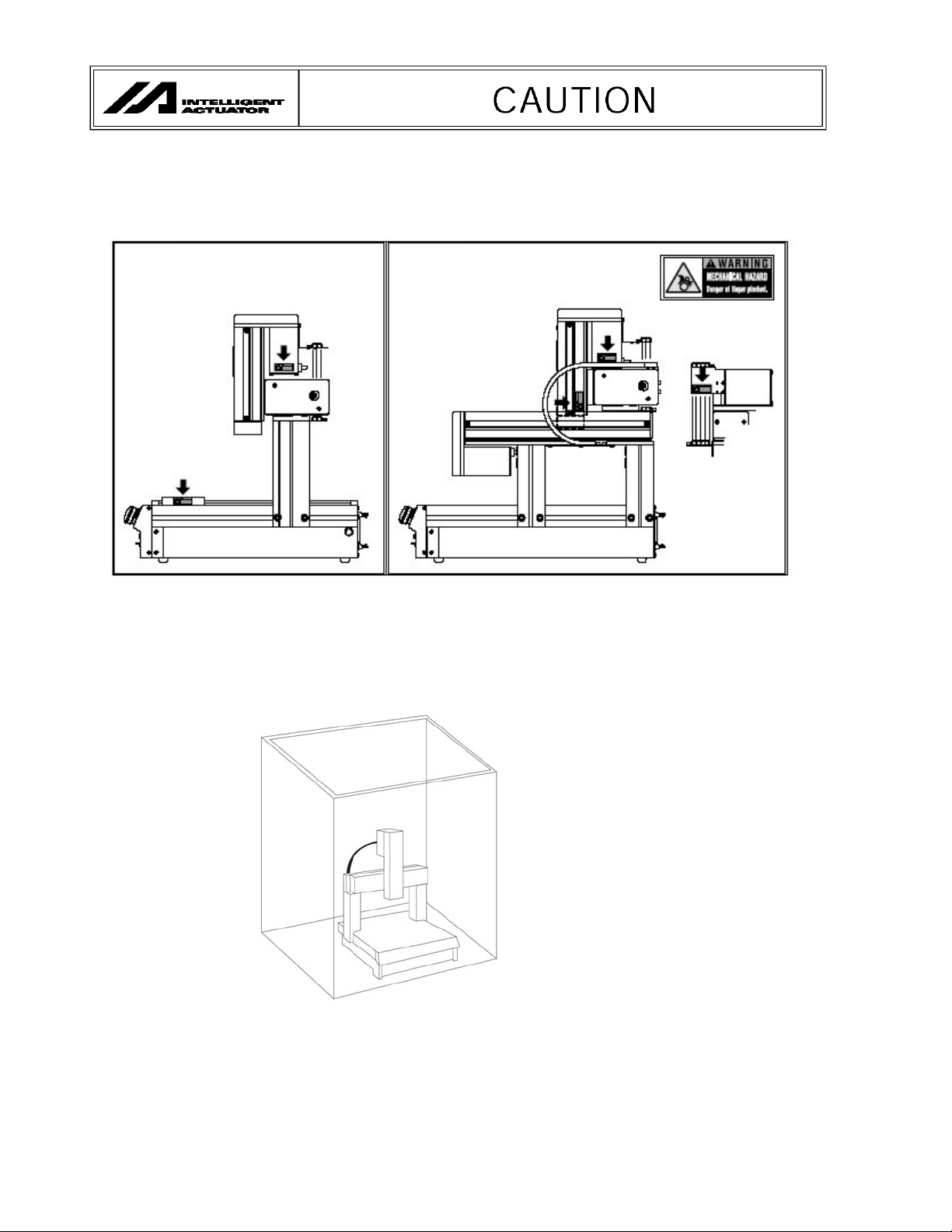
To prevent pinching of fingers, do not bring your fingers near the following areas where a warning label is
attached while the actuator is moving.
[Gate type] [Cantilever type]
Warning label
2. Installation of safety cage
It is strongly recommended that the robot be enclosed by a safety cage to ensure safety of the operator. When
the robot is enclosed by a safety cage, the robot will satisfy the Machine Directives regardless of how it is used
by the operator.
Enclose by a safety cage.
3. The maximum sound pressure level of this robot is 76.4 dB.
4. After grease has been applied to the guide and ball screw during maintenance and
inspection, be sure to install the covers.
Page 5

INTELLIGENT ACTUATOR
CE Marking
If a compliance with the CE Marking is required, please follow Overseas Standards Compliance Manual
(ME0287) that is provided separately.
Page 6

INTELLIGENT ACTUATOR
Before Use
Caution
Caution
[1] Be sure to read this operation manual to ensure the proper use of this product.
[2] Unauthorized use or reproduction of a part or all of this operation manual is prohibited.
[3] Always handle or operate the product in manners specified in this operation manual, by assuming that
whatever is not specified herein is not feasible. The warranty does not cover any defect arising from a
handling or operation not specified in this operation manual.
[4] The information contained in this operation manual is subject to change without notice for the purpose of
modification and improvement.
* If you have purchased PC software:
Always back up the parameters after installing the product or changing the parameter settings.
[5] The specifications in this manual may not apply to a custom product.
Caution
Action to Be Taken in Case of Emergency
If this product is found to be in a dangerous condition, immediately turn off all power switches of the main unit
and connected equipment or immediately disconnect all power cables from the outlets. (“Dangerous
condition” refers to a situation where the product is generating abnormal heat or smoke or has ignited and a
fire or danger to human health is anticipated.)
Contact Us
This robot has been designed and manufactured with the utmost attention and care. Should you find any
defect, however, or have any question regarding the handling of the robot, please contact IAI at the address
and numbers specified at the end of this manual.
Page 7

Table of Contents
INTELLIGENT ACTUATOR
Table of Contents
Safety Guide .................................................................................................................... 1
Chapter 1 Installation..................................................................................................... 9
1.1 Introduction ................................................................................................................... 9
1.2 Models .........................................................................................................................10
1.3 Safety Precautions.......................................................................................................11
1.4 Warranty........................................................................................................................12
1.4.1 Warranty Period....................................................................................................................12
1.4.2 Scope of Warranty................................................................................................................12
1.4.3 Honoring the Warranty......................................................................................................... 12
1.4.4 Limited Liability..................................................................................................................... 12
1.4.5
Conditions of Conformance with A pplicable Standards/Regulations, Etc., and Applications
1.4.6 Other Items Excluded from Warranty.................................................................................................. 13
2. Specifications ...........................................................................................................14
2.1 Basic Specifications.....................................................................................................14
2.2 Name and Function of Each Part.................................................................................15
2.2.1 Robot Body .......................................................................................................................... 15
2.2.2 Front Panel........................................................................................................................... 18
2.2.3 Codes Displayed on the Panel Window............................................................................... 21
2.2.4 Rear Panel ........................................................................................................................... 23
2.2.5 I/O Connector Pin Assignments ........................................................................................... 25
2.3 Interfaces of the Tabletop Robot................................................................................. 26
2.3.1 Standard Interface (Main Application Version 0.18 or Earlier)............................................. 26
2.3.2 Standard Interface (Main Application Version 0.19 or Later) ............................................... 28
2.4 External I/O Specifications...........................................................................................32
2.4.1 NPN Specification ................................................................................................................ 32
2.4.2 PNP Specification................................................................................................................. 34
2.5 External Dimensions....................................................................................................36
3. Installation Environment, Noise Measures and Other.............................................. 44
3.1 Installation Environment ..............................................................................................44
3.2 Installation....................................................................................................................45
3.2.1 Brackets (Optional) .............................................................................................................. 45
3.2.2 Installing the Load, Etc......................................................................................................... 45
3.2.3 Using the T-grooves ............................................................................................................. 46
3.3 Power Source ..............................................................................................................46
3.4 Noise Measures and Grounding ..................................................................................47
3.4.1 Grounding ............................................................................................................................ 47
3.4.2 Noise sources and noise elimination ................................................................................... 47
4. System Setup .......................................................................................................... 49
4.1 Connecting the Tabletop Robot with Peripheral Equipment.........................................49
4.2 I/O Connection Diagram (External DIOs) ....................................................................50
4.2.1 NPN specification................................................................................................................. 50
4.2.2 PNP specification ................................................................................................................. 51
............................................................. 13
Page 8

Table of Contents
INTELLIGENT ACTUATOR
Chapter 2 Operation.................................................................................................... 52
1. Operation................................................................................................................. 52
1.1 How to Start a Program ...............................................................................................52
1.2 Starting a Program by Auto-Start via Parameter Setting..............................................53
1.3 Starting via the Digital Program Selector Switch and Function Switch ........................54
2. Controller Data ........................................................................................................ 55
2.1 Data Structure..............................................................................................................55
2.2 Saving Data .................................................................................................................56
Chapter 3 X-SEL Language Data................................................................................ 58
1. Values and Symbols Used in SEL Language .......................................................... 58
2. Position Part ............................................................................................................ 71
3. Command Part ........................................................................................................ 72
Chapter 4 Commands ................................................................................................. 74
1. List of SEL Language Command Codes by Function.............................................. 74
1.1 List of Commands by Function ....................................................................................74
1.2 List of Commands in Alphabetical Order .....................................................................79
2. Explanation of Commands ...................................................................................... 84
3. Key Characteristics of Actuator Control Commands and Points to Note ............... 224
3.1 Continuous Movement Commands ...........................................................................224
3.2 PATH/PSPL Commands ............................................................................................226
3.3 CIR/ARC Commands................................................................................................. 226
3.4 CIR2/ARC2/ARCD/ARCC Commands ......................................................................226
4. Palletizing Function ............................................................................................... 227
4.1 How to Use ................................................................................................................227
4.2 Palletizing Setting ......................................................................................................227
4.3 Palletizing Calculation................................................................................................233
4.4 Palletizing Movement................................................................................................. 234
4.5 Program Examples ....................................................................................................236
5. Pseudo-Ladder Task.............................................................................................. 244
5.1 Basic Frame...............................................................................................................244
5.2 Ladder Statement Field..............................................................................................245
5.3 Points to Note ............................................................................................................245
5.4 Program Example ......................................................................................................246
Page 9

Table of Contents
INTELLIGENT ACTUATOR
Chapter 5 Maintenance and Inspection..................................................................... 247
1. Inspection Items and Inspection Intervals.............................................................. 247
2. Visual Inspection of the Exterior ............................................................................ 247
3. Visual Inspection and Cleaning ............................................................................. 247
3.1 Cleaning.....................................................................................................................247
3.2 Interior Inspection ......................................................................................................248
3.3 Internal Cleaning........................................................................................................248
4. Greasing the Guides.............................................................................................. 248
4.1 Applicable Grease .....................................................................................................248
4.2 How to Apply Grease.................................................................................................248
5. Greasing the Ball Screw ........................................................................................ 249
5.1 Applicable Grease .....................................................................................................249
5.2 How to Apply Grease.................................................................................................249
6. Timing Belt............................................................................................................. 249
6.1 Inspecting the Belt .....................................................................................................249
6.2 Applicable Belt ...........................................................................................................249
6.3 Belt Replacement Procedure.....................................................................................250
Appendix .................................................................................................................. 251
~ How to Create a Program ........................................................................................ 251
1. Position Table ........................................................................................................ 251
2. Program Format .................................................................................................... 252
3. Positioning to Five Positions.................................................................................. 253
4. How to Use TAG and GOTO ................................................................................. 254
5. Moving Back and Forth between Two Points......................................................... 255
6. Path Operation ...................................................................................................... 256
7. Output Control during Path Movement .................................................................. 257
8. Circular/Arc Operation ........................................................................................... 258
9. Home-return Completion Output ........................................................................... 259
10. Moving an Axis Selectively based on Input and Outputting a Completion Signal .. 260
11. Changing the Moving Speed ................................................................................. 261
12. Changing the Speed during Movement ................................................................. 262
13. Local/Global Classification of Variables and Flags ................................................ 263
14. How to Use Subroutines........................................................................................ 264
15. Pausing the Operation........................................................................................... 265
16. Aborting the Operation 1 (CANC).......................................................................... 266
Page 10

Table of Contents
INTELLIGENT ACTUATOR
17. Aborting the Operation 2 (STOP) .......................................................................... 267
18. Moving to a Specified Position Number ................................................................. 268
19. Conditional Jump................................................................................................... 269
20. Waiting for Multiple Inputs ..................................................................................... 270
21. How to Use Offset ................................................................................................. 271
22. Executing an Operation n Times ........................................................................... 272
23. Constant-pitch Feed Operation.............................................................................. 273
24. Jogging.................................................................................................................. 274
25. Switching Programs............................................................................................... 275
26. Aborting a Program ............................................................................................... 276
~ How to Use Internal DIOs ...................................................................................... 277
1. Internal DIs and Dedicated Functions.................................................................... 277
2. Showing User SEL Program Data on the 7-segment LED Display........................ 278
~ List of Parameters ................................................................................................. 281
1. I/O Parameters ...................................................................................................... 282
2. Parameters Common to All Axes........................................................................... 296
3. Axis-Specific Parameters....................................................................................... 299
4. Driver Card Parameters......................................................................................... 303
5. Encoder Parameters.............................................................................................. 307
6. I/O-Slot Card Parameters ...................................................................................... 308
7. Other Parameters.................................................................................................. 309
8. Manual Operation Types ....................................................................................... 314
9. Use Examples of Key Parameters......................................................................... 315
~ Error Level Control..................................................................................................... 317
~ Error List (Main application).......................................................................................319
~ Error List (Main core) .................................................................................................343
~ Troubleshooting of X-SEL Controller .........................................................................348
Trouble Report Sheet.........................................................................................................351
Change History ............................................................................................................ 352
Page 11

INTELLIGENT ACTUATOR
Safety Guide
³6DIHW\*XLGH´KDVEHHQZULWWHQWRXVHWKHPDFKLQHVDIHO\DQGVRSUHYHQWSHUVRQDOLQMXU\RUSURSHUW\
GDPDJHEHIRUHKDQG0DNHVXUHWRUHDGLWEHIRUHWKHRSHUDWLRQRIWKLVSURGXFW
Safety Precautions for Our Products
7KHFRPPRQVDIHW\SUHFDXWLRQVIRUWKHXVHRIDQ\RIRXUURERWVLQHDFKRSHUDWLRQ
1R
0RGHO
2SHUDWLRQ
'HVFULSWLRQ
6HOHFWLRQ
'HVFULSWLRQ
Ɣ 7KLVSURGXFWKDVQRWEHHQSODQQHGDQGGHVLJQHGIRUWKHDSSOLFDWLRQZKHUH
KLJKOHYHORIVDIHW\LVUHTXLUHGVRWKHJXDUDQWHHRIWKHSURWHFWLRQRI
KXPDQOLIHLVLPSRVVLEOH$FFRUGLQJO\GRQRWXVHLWLQDQ\RIWKHIROORZLQJ
DSSOLFDWLRQV
0HGLFDOHTXLSPHQWXVHGWRPDLQWDLQFRQWURORURWKHUZLVHDIIHFWKXPDQ
OLIHRUSK\VLFDOKHDOWK
0HFKDQLVPVDQGPDFKLQHU\GHVLJQHGIRUWKHSXUSRVHRIPRYLQJRU
WUDQVSRUWLQJSHRSOH)RUYHKLFOHUDLOZD\IDFLOLW\RUDLUQDYLJDWLRQIDFLOLW\
,PSRUWDQWVDIHW\SDUWVRIPDFKLQHU\6DIHW\GHYLFHHWF
Ɣ'RQRWXVHWKHSURGXFWRXWVLGHWKHVSHFLILFDWLRQV)DLOXUHWRGRVRPD\
FRQVLGHUDEO\VKRUWHQWKHOLIHRIWKHSURGXFW
Ɣ'RQRWXVHLWLQDQ\RIWKHIROORZLQJHQYLURQPHQWV
/RFDWLRQZKHUHWKHUHLVDQ\LQIODPPDEOHJDVLQIODPPDEOHREMHFWRU
H[SORVLYH
3ODFHZLWKSRWHQWLDOH[SRVXUHWRUDGLDWLRQ
/RFDWLRQZLWKWKHDPELHQWWHPSHUDWXUHRUUHODWLYHKXPLGLW\H[FHHGLQJ
WKHVSHFLILFDWLRQUDQJH
/RFDWLRQZKHUHUDGLDQWKHDWLVDGGHGIURPGLUHFWVXQOLJKWRURWKHUODUJH
KHDWVRXUFH
/RFDWLRQZKHUHFRQGHQVDWLRQRFFXUVGXHWRDEUXSWWHPSHUDWXUH
FKDQJHV
/RFDWLRQZKHUHWKHUHLVDQ\FRUURVLYHJDVVXOIXULFDFLGRUK\GURFKORULF
DFLG
/RFDWLRQH[SRVHGWRVLJQLILFDQWDPRXQWRIGXVWVDOWRULURQSRZGHU
/RFDWLRQVXEMHFWWRGLUHFWYLEUDWLRQRULPSDFW
Ɣ )RUDQDFWXDWRUXVHGLQYHUWLFDORULHQWDWLRQVHOHFWDPRGHOZKLFKLV
HTXLSSHGZLWKDEUDNH,IVHOHFWLQJDPRGHOZLWKQREUDNHWKHPRYLQJSDUW
PD\GURSZKHQWKHSRZHULVWXUQHG2))DQGPD\FDXVHDQDFFLGHQWVXFK
DVDQLQMXU\RUGDPDJHRQWKHZRUNSLHFH
1
Page 12

INTELLIGENT ACTUATOR
No.
Operation
Description
Description
2 Transportation Ɣ When carrying a heavy object, do the work with two or more persons or
utilize equipment such as crane.
Ɣ When the work is carried out with 2 or more persons, make it clear who is
to be the leader and who to be the follower(s) and communicate well with
each other to ensure the safety of the workers.
Ɣ When in transportation, consider well about the positions to hold, weight
and weight balance and pay special attention to the carried object so it
would not get hit or dropped.
Ɣ Transport it using an appropriate transportation measure.
The actuators available for transportation with a crane have eyebolts
attached or there are tapped holes to attach bolts. Follow the instructions
in the operation manual for each model.
Ɣ Do not step or sit on the package.
Ɣ Do not put any heavy thing that can deform the package, on it.
Ɣ When using a crane capable of 1t or more of weight, have an operator
who has qualifications for crane operation and sling work.
Ɣ When using a crane or equivalent equipments, make sure not to hang a
ORDGWKDWZHLJKVPRUHWKDQWKHHTXLSPHQW¶VFDSDELOLW\OLPLW
Ɣ Use a hook that is suitable for the load. Consider the safety factor of the
hook in such factors as shear strength.
Ɣ Do not get on the load that is hung on a crane.
Ɣ Do not leave a load hung up with a crane.
Ɣ Do not stand under the load that is hung up with a crane.
3 Storage and
Preservation
Ɣ The storage and preservation environment conforms to the installation
environment. However, especially give consideration to the prevention of
condensation.
Ɣ Store the products with a consideration not to fall them over or drop due to
an act of God such as earthquake.
4 Installation
and Start
(1) Installation of Robot Main Body and Controller, etc.
Ɣ Make sure to securely hold and fix the product (including the work part). A
fall, drop or abnormal motion of the product may cause a damage or injury.
Also, be equipped for a fall-over or drop due to an act of God such as
earthquake.
Ɣ Do not get on or put anything on the product. Failure to do so may cause
an accidental fall, injury or damage to the product due to a drop of
anything, malfunction of the product, performance degradation, or
shortening of its life.
Ɣ When using the product in any of the places specified below, provide a
sufficient shield.
1) Location where electric noise is generated
2) Location where high electrical or magnetic field is present
3) Location with the mains or power lines passing nearby
4) Location where the product may come in contact with water, oil or
chemical droplets
2
Page 13

INTELLIGENT ACTUATOR
3
No.
Operation
Description
,QVWDOODWLRQ
and Start
Description
(2) Cable Wiring
Ɣ 8VHRXUFRPSDQ\¶VJHQXLQHFDEOHVIRUFRQQHFWLQJEHWZHHQWKHDFWXDWRU
DQGFRQWUROOHUDQGIRUWKHWHDFKLQJWRRO
Ɣ 'RQRWVFUDWFKRQWKHFDEOH'RQRWEHQGLWIRUFLEO\'RQRWSXOOLW'RQRW
coil it around. Do not insert it. Do noWSXWDQ\KHDY\WKLQJRQLW)DLOXUHWR
GRVRPD\FDXVHDILUHHOHFWULFVKRFNRUPDOIXQFWLRQGXHWROHDNDJHRU
continuity error.
Ɣ 3HUIRUPWKHZLULQJIRUWKHSURGXFWDIWHUWXUQLQJ2))WKHSRZHUWRWKHXQLW
VRWKDWWKHUHLVQRZLULQJHUURU
Ɣ :KHQWKHGLUHFWFXUUHQWSRZHU9LVFRQQHFWHGWDNHWKHJUHDWFDUHRI
WKHGLUHFWLRQVRISRVLWLYHDQGQHJDWLYHSROHV,IWKHFRQQHFWLRQGLUHFWLRQLV
QRWFRUUHFWLWPLJKWFDXVHDILUHSURGXFWEUHDNGRZQRUPDOIXQFWLRQ
Ɣ &RQQHFWWKHFDEOHFRQQHFWRUVHFXUHO\VRWKDWWKHUHLVQRGLVFRQQHFWLRQRU
ORRVHQHVV)DLOXUHWRGRVRPD\FDXVHDILUHHOHFWULFVKRFNRUPDOIXQFWLRQ
RIWKHSURGXFW
Ɣ 1HYHUFXWDQGRUUHFRQQHFWWKHFDEOHVVXSSOLHGZLWKWKHSURGXFWIRUWKH
SXUSRVHRIH[WHQGLQJRUVKRUWHQLQJWKHFDEOHOHQJWK)DLOXUHWRGRVRPD\
FDXVHWKHSURGXFWWRPDOIXQFWLRQRUFDXVHILUH
(3) Grounding
Ɣ 7KHJURXQGLQJRSHUDWLRQVKRXOGEHSHUIRUPHGWRSUHYHQWDQHOHFWULFVKRFN
RUHOHFWURVWDWLFFKDUJHHQKDQFHWKHQRLVHUHVLVWDQFHDELOLW\DQGFRQWURO
WKHXQQHFHVVDU\HOHFWURPDJQHWLFUDGLDWLRQ
Ɣ )RUWKHJURXQGWHUPLQDORQWKH$&SRZHUFDEOHRIWKHFRQWUROOHUDQGWKH
JURXQGLQJSODWHLQWKHFRQWUROSDQHOPDNHVXUHWRXVHDWZLVWHGSDLUFDEOH
ZLWKZLUHWKLFNQHVVPP
2
$:*RUHTXLYDOHQWRUPRUHIRUJURXQGLQJ
ZRUN)RUVHFXULW\JURXQGLQJLWLVQHFHVVDU\WRVHOHFWDQDSSURSULDWHZLUH
WKLFNQHVVVXLWDEOHIRUWKHORDG3HUIRUPZLULQJWKDWVDWLVILHVWKH
VSHFLILFDWLRQVHOHFWULFDOHTXLSPHQWWHFKQLFDOVWDQGDUGV
Ɣ 3HUIRUP&ODVV'*URXQGLQJIRUPHU&ODVV*URXQGLQJZLWKJURXQG
UHVLVWDQFHRUEHORZ
Page 14

INTELLIGENT ACTUATOR
No.
4 Installation
Operation
Description
and Start
Description
(4) Safety Measures
Ɣ When the work is carried out with 2 or more persons, make it clear who is
to be the leader and who to be the follower(s) and communicate well with
each other to ensure the safety of the workers.
Ɣ When the product is under operation or in the ready mode, take the safety
measures (such as the installation of safety and protection fence) so that
QRERG\FDQHQWHUWKHDUHDZLWKLQWKHURERW¶VPRYDEOHUDQJH:KHQWKH
robot under operation is touched, it may result in death or serious injury.
Ɣ 0DNHVXUHWRLQVWDOOWKHHPHUJHQF\VWRSFLUFXLWVRWKDWWKHXQLWFDQEH
VWRSSHGLPPHGLDWHO\LQDQHPHUJHQF\GXULQJWKHXQLWRSHUDWLRQ
Ɣ7DNHWKHVDIHW\PHDVXUHQRWWRVWDUWXSWKHXQLWRQO\ZLWKWKHSRZHUWXUQLQJ
ON. Failure to do so may start up the machine suddenly and cause an
LQMXU\RUGDPDJHWRWKHSURGXFW
Ɣ Take the safety measure not to start up the machine only with the
HPHUJHQF\VWRSFDQFHOODWLRQRUUHFRYHU\DIWHUWKHSRZHUIDLOXUH)DLOXUHWR
do so may result in an electric shock or injury due to unexpected power
input.
Ɣ :KHQWKHLQVWDOODWLRQRUDGMXVWPHQWRSHUDWLRQLVWREHSHUIRUPHGJLYH
FOHDUZDUQLQJVVXFKDV³8QGHU2SHUDWLRQ'RQRWWXUQ21WKHSRZHU´HWF
Sudden power input may cause an electric shock or injury.
Ɣ Take the measure so that the work part is not dropped in power failure or
HPHUJHQF\VWRS
Ɣ :HDUSURWHFWLRQJORYHVJRJJOHRUVDIHW\VKRHVDVQHFHVVDU\WRVHFXUH
safety.
Ɣ 'RQRWLQVHUWDILQJHURUREMHFWLQWKHRSHQLQJVLQWKHSURGXFW)DLOXUHWRGR
VRPD\FDXVHDQLQMXU\HOHFWULFVKRFNGDPDJHWRWKHSURGXFWRUILUH
Ɣ :KHQUHOHDVLQJWKHEUDNHRQDYHUWLFDOO\RULHQWHGDFWXDWRUH[HUFLVH
SUHFDXWLRQQRWWRSLQFK\RXUKDQGRUGDPDJHWKHZRUNSDUWVZLWKWKH
DFWXDWRUGURSSHGE\JUDYLW\
7HDFKLQJ Ɣ When the work is carried out with 2 or more persons, make it clear who is
to be the leader and who to be the follower(s) and communicate well with
each other to ensure the safety of the workers.
Ɣ 3HUIRUPWKHWHDFKLQJRSHUDWLRQIURPRXWVLGHWKHVDIHW\SURWHFWLRQIHQFHLI
SRVVLEOH,QWKHFDVHWKDWWKHRSHUDWLRQLVWREHSHUIRUPHGXQDYRLGDEO\
LQVLGHWKHVDIHW\SURWHFWLRQIHQFHSUHSDUHWKH³6WLSXODWLRQVIRUWKH
2SHUDWLRQ´DQGPDNHVXUHWKDWDOOWKHZRUNHUVDFNQRZOHGJHDQG
understand them well.
Ɣ When the operation is to be performed inside the safety protection fence,
WKHZRUNHUVKRXOGKDYHDQHPHUJHQF\VWRSVZLWFKDWKDQGZLWKKLPVRWKDW
WKHXQLWFDQEHVWRSSHGDQ\WLPHLQDQHPHUJHQF\
Ɣ When the operation is to be performed inside the safety protection fence,
LQDGGLWLRQWRWKHZRUNHUVDUUDQJHDZDWFKPDQVRWKDWWKHPDFKLQHFDQ
EHVWRSSHGDQ\WLPHLQDQHPHUJHQF\$OVRNHHSZDWFKRQWKHRSHUDWLRQ
so that any third person can not operate the switches carelessly.
Ɣ 3ODFHDVLJQ³8QGHU2SHUDWLRQ´DWWKHSRVLWLRQHDV\WRVHH
Ɣ :KHQUHOHDVLQJWKHEUDNHRQDYHUWLFDOO\RULHQWHGDFWXDWRUH[HUFLVH
SUHFDXWLRQQRWWRSLQFK\RXUKDQGRUGDPDJHWKHZRUNSDUWVZLWKWKH
DFWXDWRUGURSSHGE\JUDYLW\
* Safety protection Fence : In the case that there is no safety protection
IHQFHWKHPRYDEOHUDQJHVKRXOGEHLQGLFDWHG
4
Page 15

INTELLIGENT ACTUATOR
5
No.
Operation
Description
Description
6 Trial Operation Ɣ When the work is carried out with 2 or more persons, make it clear who is
to be the leader and who to be the follower(s) and communicate well with
each other to ensure the safety of the workers.
Ɣ After the teaching or programming operation, perform the check operation
one step by one step and then shift to the automatic operation.
Ɣ When the check operation is to be performed inside the safety protection
fence, perform the check operation using the previously specified work
procedure like the teaching operation.
Ɣ Make sure to perform the programmed operation check at the safety
speed. Failure to do so may result in an accident due to unexpected
motion caused by a program error, etc.
Ɣ Do not touch the terminal block or any of the various setting switches in
the power ON mode. Failure to do so may result in an electric shock or
malfunction.
7 Automatic
Operation
Ɣ Check before starting the automatic operation or rebooting after operation
stop that there is nobody in the safety protection fence.
Ɣ Before starting automatic operation, make sure that all peripheral
equipment is in an automatic-operation-ready state and there is no alarm
indication.
Ɣ Make sure to operate automatic operation start from outside of the safety
protection fence.
Ɣ In the case that there is any abnormal heating, smoke, offensive smell, or
abnormal noise in the product, immediately stop the machine and turn
OFF the power switch. Failure to do so may result in a fire or damage to
the product.
Ɣ When a power failure occurs, turn OFF the power switch. Failure to do so
may cause an injury or damage to the product, due to a sudden motion of
the product in the recovery operation from the power failure.
Page 16

INTELLIGENT ACTUATOR
No.
Operation
Description
8 Maintenance
and Inspection
Ɣ When the work is carried out with 2 or more persons, make it clear who is
to be the leader and who to be the follower(s) and communicate well with
Description
each other to ensure the safety of the workers.
Ɣ Perform the work out of the safety protection fence, if possible. In the case
that the operation is to be performed unavoidably inside the safety
SURWHFWLRQIHQFHSUHSDUHWKH³6WLSXODWLRQVIRUWKH2SHUDWLRQ´DQGPDNH
sure that all the workers acknowledge and understand them well.
Ɣ When the work is to be performed inside the safety protection fence,
basically turn OFF the power switch.
Ɣ When the operation is to be performed inside the safety protection fence,
the worker should have an emergency stop switch at hand with him so that
the unit can be stopped any time in an emergency.
Ɣ When the operation is to be performed inside the safety protection fence,
in addition to the workers, arrange a watchman so that the machine can
be stopped any time in an emergency. Also, keep watch on the operation
so that any third person can not operate the switches carelessly.
Ɣ 3ODFHDVLJQ³8QGHU2SHUDWLRQ´DWWKHSRVLWLRQHDV\WRVHH
Ɣ For the grease for the guide or ball screw, use appropriate grease
according to the Operation Manual for each model.
Ɣ Do not perform the dielectric strength test. Failure to do so may result in a
damage to the product.
Ɣ When releasing the brake on a vertically oriented actuator, exercise
precaution not to pinch your hand or damage the work parts with the
actuator dropped by gravity.
Ɣ The slider or rod may get misaligned OFF the stop position if the servo is
turned OFF. Be careful not to get injured or damaged due to an
unnecessary operation.
Ɣ Pay attention not to lose the cover or untightened screws, and make sure
to put the product back to the original condition after maintenance and
inspection works.
8VHLQLQFRPSOHWHFRQGLWLRQPD\FDXVHGDPDJHWRWKHSURGXFWRUDQLQMXU\
6DIHW\SURWHFWLRQ)HQFH,QWKHFDVHWKDWWKHUHLVQRVDIHW\SURWHFWLRQ
fence, the movable range should be indicated.
9 Modification
and Dismantle
Ɣ Do not modify, disassemble, assemble or use of maintenance parts not
specified based at your own discretion.
10 Disposal Ɣ When the product becomes no longer usable or necessary, dispose of it
properly as an industrial waste.
Ɣ When removing the actuator for disposal, pay attention to drop of
components when detaching screws.
Ɣ Do not put the product in a fire when disposing of it.
The product may burst or generate toxic gases.
11 Other Ɣ Do not come close to the product or the harnesses if you are a person
who requires a support of medical devices such as a pacemaker. Doing so
may affect the performance of your medical device.
Ɣ6HH2YHUVHDV6SHFLILFDWLRQV&RPSOLDQFH0DQXDOWRFKHFNZKHWKHU
complies if necessary.
Ɣ For the handling of actuators and controllers, follow the dedicated
operation manual of each unit to ensure the safety.
6
Page 17

INTELLIGENT ACTUATOR
7
Alert Indication
7KHVDIHW\SUHFDXWLRQVDUHGLYLGHGLQWR³'DQJHU´³:DUQLQJ´³&DXWLRQ´DQG³1RWLFH´DFFRUGLQJWRWKH
ZDUQLQJOHYHODVIROORZVDQGGHVFULEHGLQWKH2SHUDWLRQ0DQXDOIRUHDFKPRGHO
/HYHO 'HJUHHRI'DQJHUDQG'DPDJH 6\PERO
'DQJHU
:DUQLQJ
&DXWLRQ
1RWLFH
7KLVLQGLFDWHVDQLPPLQHQWO\KD]DUGRXVVLWXDWLRQZKLFKLIWKH
SURGXFWLVQRWKDQGOHGFRUUHFWO\ZLOOUHVXOWLQGHDWKRUVHULRXVLQMXU\
7KLVLQGLFDWHVDSRWHQWLDOO\KD]DUGRXVVLWXDWLRQZKLFKLIWKHSURGXFW
LVQRWKDQGOHGFRUUHFWO\FRXOGUHVXOWLQGHDWKRUVHULRXVLQMXU\
7KLVLQGLFDWHVDSRWHQWLDOO\KD]DUGRXVVLWXDWLRQZKLFKLIWKHSURGXFW
LVQRWKDQGOHGFRUUHFWO\PD\UHVXOWLQPLQRULQMXU\RUSURSHUW\
GDPDJH
7KLVLQGLFDWHVORZHUSRVVLELOLW\IRUWKHLQMXU\EXWVKRXOGEHNHSWWR
XVHWKLVSURGXFWSURSHUO\
'DQJHU
:DUQLQJ
&DXWLRQ
1RWLFH
Page 18

INTELLIGENT ACTUATOR
&DXWLRQLQ+DQGOLQJ
'RQRWVHWVSHHGVDQGDFFHOHUDWLRQVGHFHOHUDWLRQVHTXDOWRRUJUHDWHU
WKDQWKHUHVSHFWLYHUDWLQJV
,IWKHDFWXDWRULVRSHUDWHGDWDVSHHGRUDFFHOHUDWLRQGHFHOHUDWLRQH[FHHGLQJWKHDOORZDEOH
YDOXHDEQRUPDOQRLVHRUYLEUDWLRQIDLOXUHRUVKRUWHUOLIHPD\UHVXOW
,QWKHFDVHRILQWHUSRODWHGRSHUDWLRQRIFRPELQHGD[HVWKHVSHHGDQG
DFFHOHUDWLRQGHFHOHUDWLRQVHWWLQJVVKRXOGFRUUHVSRQGWRWKHPLQLPXPYDOXHVDPRQJDOO
FRPELQHGD[HV
.HHSWKHORDGPRPHQWZLWKLQWKHDOORZDEOHYDOXH
,IWKHDFWXDWRULVRSHUDWHGXQGHUDORDGHTXDOWRRUJUHDWHUWKDQWKHDOORZDEOHORDGPRPHQW
DEQRUPDOQRLVHRUYLEUDWLRQIDLOXUHRUVKRUWHUOLIHPD\UHVXOW,QDQH[WUHPHFDVHIODNLQJ
PD\RFFXU
0DNHVXUHWRDWWDFKWKHDFWXDWRUSURSHUO\E\IROORZLQJWKLV2SHUDWLRQ
PDQXDO
8VLQJWKHSURGXFWZLWKWKHDFWXDWRUQRWEHLQJFHUWDLQO\UHWDLQHGRUDIIL[HGPD\FDXVHDEQRUPDO
QRLVHYLEUDWLRQPDOIXQFWLRQRUVKRUWHQWKHSURGXFWOLIH
8
Page 19

INTELLIGENT ACTUATOR
Chapter 1 Installation
Chapter 1 Installation
1.1 Introduction
Thank you for purchasing the Tabletop Robot.
Inappropriate use or handling will prevent this product from demonstrating its full function and may
even cause unexpected failure or result in a shortened service life. Please read this manual carefully,
and handle the product with due care and operate it correctly. Keep this manual in a safe place and
reference relevant items when needed.
The Tabletop Robot is an all-in-one actuator that can be used as an independent standalone robot.
The robot can also be used to control various peripheral equipment by utilizing the robot’s built-in
controller and supplied input/output (general-purpose input/output) connector. In general, connecting
additional equipment will make the system larger and more complex, which often increases the
probability of accident due to malfunction, carelessness, etc. If you are configuring the Tabletop Robot
to operate with other equipment, please take sufficient safety measures.
x Actuator duty
Based on the relationship of service life and precision, keep the duty to 50% or less for all actuators
of IAI as a guideline.
The duty is calculated by the formula below:
Chapter 1 Installation
Duty (%) =
hours Operating
hours Stopped hours Operating
X 100
x After turning off the main power, be sure to wait for at least 5 seconds before turning it on.
Any shorter interval may generate “E88: Power system error (Other).”
x Do not plug in/out the connectors while the power is still supplied to the controller. Doing so may
result in malfunction.
If you have purchased our optional PC software and/or teaching pendant, read the respective
operation manuals, as well.
* Utmost effort has been made to ensure that the information contained in this manual is true and
correct. However, should you find any error or if you have any comment regarding the content,
please contact IAI.
9
Page 20

INTELLIGENT ACTUATOR
1.2 Models
Example of Model Code
Chapter 1 Installation
[1] [2] [3] [4] [5] [6]
Chapter 1 Installation
Model table
[1] Series [2] Type
TT
A2
(Gate 2-axis type)
C2
(Cantilever 2-axis
type)
A3
(Gate 3-axis type)
C3
(Cantilever 3-axis
type)
[3] Encoder
type
I
(Incremental)
[4] XY stroke
(mm)
2020
(200 mm)
4040
(400 mm)
[5] Z stroke [6] Options
DV
(DeviceNet)
CC
(CC-Link)
PR
(ProfiBus)
ET
05B
(50 mm)
10B
(100 mm)
(Ethernet)
FT
(Mounting bracket)
P
(External I/O: PNP
specification)
10
Page 21

11
Chapter 1 Installation
Chapter 1 Installation
INTELLIGENT ACTUATOR
Caution
1.3 Safety Precautions
This system product was developed as a drive unit for an automated machine, etc., and as such the
maximum torque and speed are limited to levels acceptable for an automatically driven machine.
However, strict observance of the following items is requested to prevent unforeseen danger.
1. Do not handle this product in manners not specified in this manual. If you have any question
regarding the content of this manual, please contact IAI.
2. Do not enter the operation area of the machine while the machine is operating or ready to operate
(the controller power is on). If the machine is used in a place accessible to other people, provide an
appropriate safety measure such as enclosing the machine with a cage.
3. When assembling/adjusting or maintaining/inspecting the machine, always turn off the controller
power at the source beforehand. The operator should display in a conspicuous place a plate or
other sign saying that operation is in progress and that the power should not be turned on. The
operator should keep the entire power cable beside him or her to prevent another person from
inadvertently plugging in the cable.
4. When two or more operators are to work together, set call-out signals to ensure safety of all
personnel during the work. In particular, a person turning on/off the power or moving an axiseither
via a motor or manuallymust always say what he or she is going to do out loud and confirm the
responses from the others first before actually performing the operation.
Page 22

1.4 Warranty
1.4.1 Warranty Period
One of the following periods, whichever is shorter:
1.4.2 Scope of Warranty
Our products are covered by warranty when all of the following conditions are met. Faulty products
Chapter 1 Installation
covered by warranty will be replaced or repaired free of charge:
(1) The breakdown or problem in question pertains to our product as delivered by us or our authorized
(2) The breakdown or problem in question occurred during the warranty period.
(3) The breakdown or problem in question occurred while the product was in use for an appropriate
(4) The breakdown of problem in question was caused by a specification defect or problem, or by a
Chapter 1 Installation
INTELLIGENT ACTUATOR
18 months after shipment from our company
12 months after delivery to the specified location
dealer.
purpose under the conditions and environment of use specified in the operation manual and catalog.
quality issue with our product.
Note that breakdowns due to any of the following reasons are excluded from the scope of warranty:
[1] Anything other than our product
[2] Modification or repair performed by a party other than us (unless we have approved such
modification or repair)
[3] Anything that could not be easily predicted with the level of science and technology available at
the time of shipment from our company
[4] A natural disaster, man-made disaster, incident or accident for which we are not liable
[5] Natural fading of paint or other symptoms of aging
[6] Wear, depletion or other expected result of use
[7] Operation noise, vibration or other subjective sensation not affecting function or maintenance
Note that the warranty only covers our product as delivered and that any secondary loss arising from a
breakdown of our product is excluded from the scope of warranty.
1.4.3 Honoring the Warranty
As a rule, the product must be brought to us for repair under warranty.
1.4.4 Limited Liability
(1) We shall assume no liability for any special damage, consequential loss or passive loss such as a
loss of expected profit arising from or in connection with our product.
(2) We shall not be liable for any program or control method created by the customer to operate our
product or for the result of such program or control method.
12
Page 23

13
Chapter 1 Installation
Chapter 1 Installation
INTELLIGENT ACTUATOR
1.4.5 Conditions of Conformance with A pplicable Standards/Regulations, Etc., and Applications
(1) If our product is combined with another product or any system, device, etc., used by the customer,
the customer must first check the applicable standards, regulations and/or rules. The customer is also
responsible for confirming that such combination with our product conforms to the applicable
standards, etc. In such a case we will not be liable for the conformance of our product with the
applicable standards, etc.
(2) Our product is for general industrial use. It is not intended or designed for the applications specified
below, which require a high level of safety. Accordingly, as a rule our product cannot be used in these
applications. Contact us if you must use our product for any of these applications:
[1] Medical equipment pertaining to maintenance or management of human life or health
[2] A mechanism or mechanical equipment intended to move or transport people (such as a
vehicle, railway facility or aviation facility)
[3] Important safety parts of mechanical equipment (such as safety devices)
[4] Equipment used to handle cultural assets, art or other irreplaceable items
(3) Contact us at the earliest opportunity if our product is to be used in any condition or environment that
differs from what is specified in the catalog or operation manual.
1.4.6 Other Items Excluded from Warranty
The price of the product delivered to you does not include expenses associated with programming, the
dispatch of engineers, etc. Accordingly, a separate fee will be charged in the following cases even during
the warranty period:
[1] Guidance for installation/adjustment and witnessing of test operation
[2] Maintenance and inspection
[3] Technical guidance and education on operating/wiring methods, etc.
[4] Technical guidance and education on programming and other items related to programs
Page 24

2. Speci¿cations
Chapter 1 Installation
INTELLIGENT ACTUATOR
2. Specifications
2.1 Basic Specifications
Item Description
Number of controlled axes Maximum 3 axes (Factory setting)
Power-source voltage
Power-source frequency 50 Hz/60 Hz
Withstand voltage 2000 V 1 minute
Rush current 15 A (100 VAC), 30 A (200 VAC)
Leak current 0.75 mA (60 Hz)
Resistance to momentary power failure
Electric-shock protection mechanism Class 1 basic isolation
Surrounding air temperature range
Surrounding humidity range 20% to 90% (Non-condensing)
Storage temperature range
Maximum speed 300 mm/sec
Rated acceleration Gate type: 0.3G, Cantilever type: 0.2G
Programming language Super SEL language
Program steps 6000 steps (total)
Number of positions 3000 positions
Number of programs 64 programs
Multi-tasking 16 programs
Standard inputs 16 points (General-purpose inputs, port Nos. 016 to 031)
Standard outputs 16 points (General-purpose outputs, port Nos. 316 to 331)
Dedicated inputs
Dedicated outputs
Serial communication For teaching pendant/PC connection
Supported Fieldbus standards
Single-phase, 100 to 230 VAC
Max 500
5
Cto40C
-10
Digital switch for program number input
Function switch, etc.
Alarm status indicator LED
Ready status indicator LED
Emergency-stop status indicator LED
Home-return completion status indicator LED, etc.
CC-LINK DeviceNet Profibus
ModBus/TCP Ethernet
s
Cto65C
10%
Note: The parameters are normally set to the above general-purpose input and general-purpose output
port numbers before shipment.
14
Page 25

15
INTELLIGENT ACTUATOR
Chapter 1 Installation
2. Speci¿cations
2.2 Name and Function of Each Part
2.2.1 Robot Body
Gate 2-axis type
Y-axis (axis 2) actuator
Y slider
T-groove (4 locations)
Gate 3-axis type
Y-slider position
adjustment volume
X slider
Front panel
Rear panel
Y-axis (axis 2) actuator
T-groove (4 locations)
Z-slider position
adjustment volume
Z-axis (axis 3) actuator
Z slider
Y-slider position
adjustment volume
X slider
Front panel
Page 26

INTELLIGENT ACTUATOR
Cantilever 2-axis type
Y-axis (axis 2) actuator Y slider
Chapter 1 Installation
X-axis (axis 1) actuator
Y-slider position
adjustment volume
X-slider position
adjustment volume
2. Speci¿cations
Front panel
Cantilever 3-axis type
T-groove
(4 locations)
Rear panel
Z-slider position
adjustment volume
16
Y-axis (axis 2) actuator
Front panel
Z-axis (axis 3) actuator
X-slider position
adjustment
volume
X-axis (axis 1) actuator
Y-slider position
adjustment
volume
T-groove (4 locations)
Page 27

17
INTELLIGENT ACTUATOR
Chapter 1 Installation
2. Speci¿cations
x X-axis actuator
Various loads can be attached to the X-axis actuator of the gate-type robot.
x Y-axis actuator
Various tools can be attached to the Y-axis actuator of the 2-axis robot.
x Z-axis actuator
Various tools can be attached to the Z-axis actuator of the 3-axis robot.
x T-groove
Auxiliary tools can be attached by utilizing the T-grooves/T-slots and nuts.
x Position adjustment volume
You can fine-tune the slider position easily by turning this volume with a flathead screwdriver, etc.
This function is useful when manually adjusting the slider position to read position data.
This adjustment volume is provided on various actuators.
(Note) Before fine-tuning the slider position using this volume, be sure to actuate an emergency
stop.
Do not insert an adjustment tool, finger or other object into the operating range of the robot
while the servo is ON or slider is operating.
Page 28
INTELLIGENT ACTUATOR
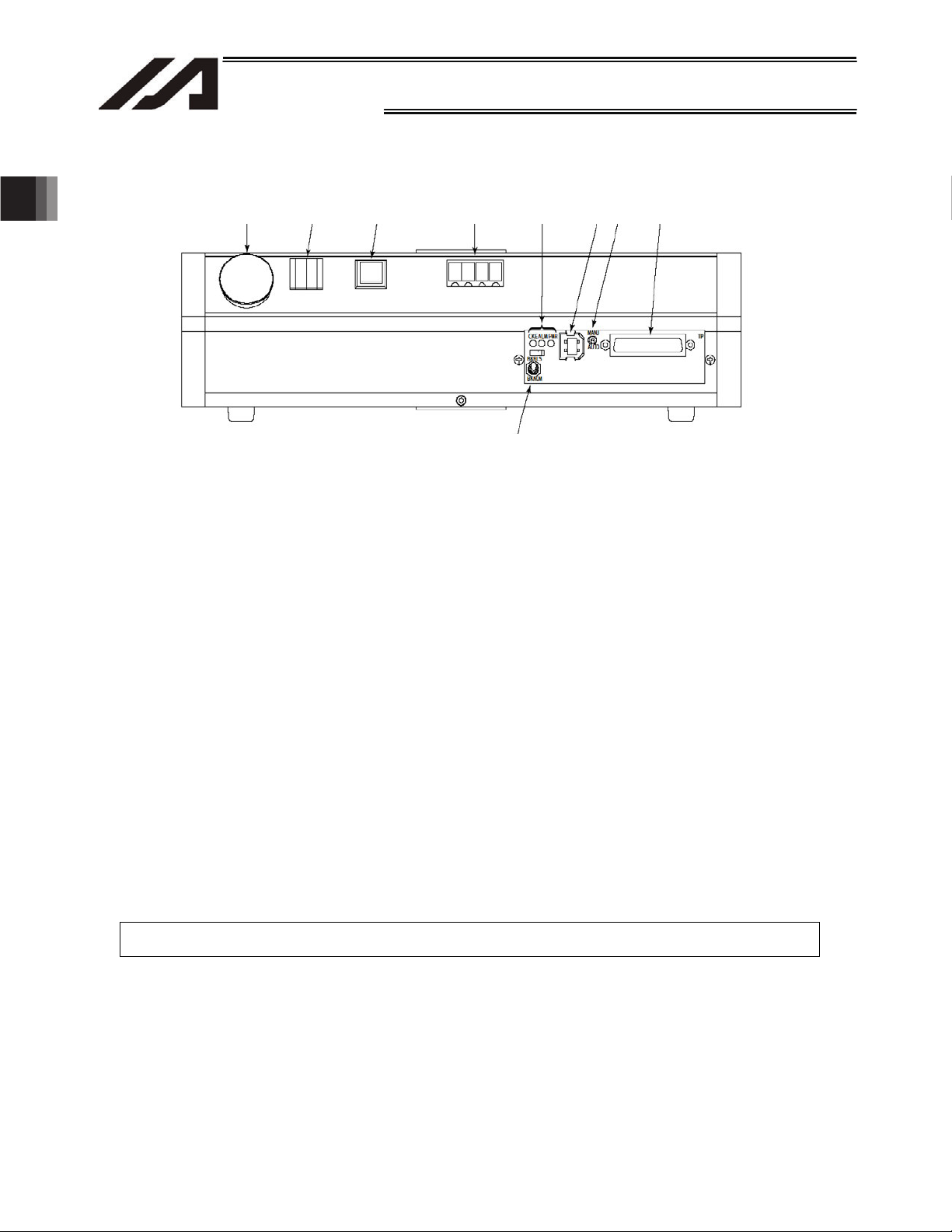
2.2.2 Front Panel
Chapter 1 Installation
2. Speci¿cations
[1] [2] [3] [4] [5]
[1]
Emergency button (emergency-stop button)
[6]
[7]
[8]
[9]
This switch is used to cut off the drive power when the robot must be stopped in case of
emergency.
[2] Digital program selector switch
This switch provides a 2-digit decimal digital switch input for selecting the program you want to
start from among the group of programs stored in the Tabletop Robot. Pressing the start switch [3]
will start the selected program.
[3] Start switch (function switch)
This switch issues a trigger to start the program set by the digital program selector switch [2].
(Factory setting)
This switch is enabled in the AUTO mode.
In the MANU mode, this switch is enabled after the teaching pendant or PC software has been
connected online. (Once the teaching pendant or PC software is connected online, the switch will
remain enabled until the robot is restarted (via software reset), even after the connection is
switched offline.)
(This switch turns ON/OFF input port No. 000. Since I/O parameter No. 30 is set to “1” at the
factory, input port No. 000 is used as the program start signal (dedicated input). You can use input
port No. 000 as a general-purpose input by setting I/O parameter No. 30 to “0.”)
Note: The parameters are normally set to the above input port numbers before shipment.
18
Page 29

19
Chapter 1 Installation
2. Speci¿cations
INTELLIGENT ACTUATOR
[4] Panel window
The panel window consists of a 4-digit, 7-segment LED display and four LED lamps indicating the
status of the robot.
The status indicated by each LED lamp when the lamp is lit is explained below:
RDY: The robot is ready to perform PIO program operation.
(This lamp is connected to dedicated output No. 301.)
ALM: An error of operation-cancellation level or higher has occurred.
(This lamp is connected to dedicated output No. 300.)
EMG: An emergency stop has been actuated.
(This lamp is connected to dedicated output No. 302.)
HPS: All axes have completed their home return.
(This lamp is connected to dedicated output No. 304.)
For the specific codes shown on the 4-digit, 7-segment LED display, refer to 2.2.3, “Codes
Displayed on the Panel Window” or the “Error Code Table.”
Note: The parameters are normally set to the above output port numbers before shipment.
[5] LED indicator lamps
The status indicated by each LED lamp when the lamp is lit is explained below:
CKE: System clock error
ALM: CPU alarm (system-down level error)
PWR: Power ON
[6] Brake switch
This switch is used to release the axis brake.
Tilt the switch upward (BKRLS side) to forcibly release the brake, or tilt it downward (BKNOM
side) to allow the brake to be controlled automatically by the controller. Set this switch to the
BKNOM side in normal conditions of use.
[7] USB connector
This connector is used for USB connection. Use it to connect the PC software to the controller via
USB cable.
Applicable connector: USB connector B: XM7B-0442
Mating connector: USB cable
Notes
x If the USB port is used, all TT robots comprising the system must be connected one by
one to install the USB driver included in the CD-ROM “X-SEL PC Software IA-101-TTUSB.” For details on how to install the driver, refer to the operation manual for X-SEL PC
software.
x If the USB port is used, a dummy plug must be connected to the teaching connector [9].
Dummy plug model: DP-1
[8] Mode switch
This switch is used to specify the operation mode of the Tabletop Robot.
Tilt the switch upward to select the MANU mode (manual mode), or tilt it downward to select the
AUTO mode (automatic mode).
Operations from the teaching pendant or PC software (such as teaching) must be performed in
the MANU mode. (They cannot be performed in the AUTO mode.)
Auto program start is enabled in the AUTO mode. (The function cannot be used in the MANU
mode.)
Page 30

2. Speci¿cations
Chapter 1 Installation
INTELLIGENT ACTUATOR
[9] Teaching connector When an optional teaching pendant or PC is connected, this D-sub, 25-
pin connector will be used to input program and position data in the
MANU mode.
Interface Specifications of Teaching Serial Interface
Item Description
Connector name TP
Connector DSUB-25 XM3B-2542-502L (Omron)
Communication
method
RS232C-compliant, start-stop synchronous
method
Baud rate 38.4 kbps max.; half-duplex communication
Maximum
connection distance
10 m (38.4 kbps)
Interface standard RS232C
Connected to X-SEL teaching pendant
Interface Specifications of Teaching Serial Interface
Item No. Direction Signal name Description
Terminal
assignments
1 FG Frame ground
2 Out TXD Transmitted data
3 In RXD Received data
4 Out RTS Request to send
5 In CTS Clear to send
6 Out DSR Equipment ready
7 SG Signal ground
8
9 In Connection prohibited
10 In Connection prohibited
11
12 Out EMGOUT Emergency stop
13 In EMGIN
14
15 Out Connection prohibited
16 Out Connection prohibited
17 Out Connection prohibited
Power output
18 Out VCC
(5-V power source for
teaching pendant)
19 In ENBTBX Enable input
20 In DTR Terminal ready
21
22
23 Out EMGS Emergency-stop status
24
25 SG Signal ground
20
Page 31

21
INTELLIGENT ACTUATOR
Chapter 1 Installation
2. Speci¿cations
2.2.3 Codes Displayed on the Panel Window
(1) Application
Display Priority (*1) Description
AC power is cut off (including momentary power failure or drop in
power-source voltage).
System-down level error
Writing data to the flash ROM.
Emergency stop is being actuated (except during the update
Safety gate is open (except during the update mode).
Cold-start level error
Cold-start level error
Operation-cancellation level error
Operation-cancellation level error
Waiting for a drive-source cutoff reset input (except during the
update mode).
Operation is in pause (waiting for restart) (except during the
update mode).
All servo axes are interlocked (except during the update mode).
Message level error
Message level error
Core update mode
Core update is in progress.
Core update has completed.
Slave update mode
Slave update is in progress.
Slave update has completed.
Running a program (last started program); “No.” indicates program
number.
Initialization sequence number
Debug mode
Ready status (auto mode)
Ready status (manual mode)
Deadman switch OFF (manual mode)
(*1) The priority increases as the number decreases.
Page 32

2. Speci¿cations
Chapter 1 Installation
INTELLIGENT ACTUATOR
(2) Core
Display Priority (*1) Description
AC power is cut off (including momentary power failure or drop in
power-source voltage).
Cold-start level error
Cold-start level error
Operation-cancellation level error
Operation-cancellation level error
Message level error
Message level error
Application update mode
Application update is in progress.
Application update has completed.
Hardware test mode process
Clearing the application flash ROM.
Application flash ROM has been cleared.
Jump to the application
Core flash-ROM check process
Application flash-ROM check process
SDRAM check process
(*1) The priority increases as the number decreases.
22
Page 33

23
INTELLIGENT ACTUATOR
Chapter 1 Installation
2. Speci¿cations
2.2.4 Rear Panel
[12]
[11]
[9] Power
[13]
connector
Connect the power cable to this connector.
Use the supplied socket for cable connection with the power connector.
(Note) The allowable range of power-source voltage is 100 to 230 VAC (r10%).
Providing a power cable and attaching it to the supplied socket is the user’s responsibility.
Use a cable appropriate for the power-source voltage used.
How to attach a cable to the supplied socket
[9]
[10]
M3X16
Tightening torque:
6 kgcmf or less
M3X5
Tightening torque: 4 kgcmf or less
White
Sheath
Black
M3X10
Page 34

2. Speci¿cations
Chapter 1 Installation
INTELLIGENT ACTUATOR
[10] Ground terminal
This terminal is used to connect FG of the enclosure to ground.
[11] Power switch
[12] Gate X-axis actuator position adjustment volume (This volume is not available on the cantilever
type.)
You can fine-tune the X-axis slider position easily by turning this volume with a flathead
screwdriver, etc. This function is useful when manually adjusting the slider position to read
position data.
(Note) Before fine-tuning the slider position using this volume, be sure to actuate an emergency
stop. Do not insert an adjustment tool, finger or other object into the operating range of the
robot while the servo is ON or slider is operating.
[13] I/O connector (general-purpose I/Os)
This general-purpose I/O connector is used to connect peripheral equipment, etc.
It is a 34-pin flat connector that comprises 16 general-purpose input/16 general-purpose output
DIOs.
24
Page 35

25
Chapter 1 Installation
2. Speci¿cations
INTELLIGENT ACTUATOR
2.2.5 I/O Connector Pin Assignments
Pin No. Category Port No. Function Cable color
1 +24 V I/O power supply + 24 V Brown-1
2 016 General-purpose input Red-1
3 017 General-purpose input Orange-1
4 018 General-purpose input Yellow-1
5 019 General-purpose input Green-1
6 020 General-purpose input Blue-1
7 021 General-purpose input Purple-1
8 022 General-purpose input Gray-1
9 023 General-purpose input White-1
10 024 General-purpose input Black-1
11 025 General-purpose input Brown-2
12 026 General-purpose input Red-2
13 027 General-purpose input Orange-2
14 028 General-purpose input Yellow-2
15 029 General-purpose input Green-2
16 030 General-purpose input Blue-2
17
18 316 General-purpose output Gray-2
19 317 General-purpose output White-2
20 318 General-purpose output Black-2
21 319 General-purpose output Brown-3
22 320 General-purpose output Red-3
23 321 General-purpose output Orange-3
24 322 General-purpose output Yellow-3
25 323 General-purpose output Green-3
26 324 General-purpose output Blue-3
27 325 General-purpose output Purple-3
28 326 General-purpose output Gray-3
29 327 General-purpose output White-3
30 328 General-purpose output Black-3
31 329 General-purpose output Brown-4
32 330 General-purpose output Red-4
33
34 0 V I/O power supply 0 V Yellow-4
Input
031 General-purpose input Purple-2
Output
331 General-purpose output Orange-4
Note: The parameters are normally set to the above port numbers before shipment.
I/O flat cable (supplied) Model: CB-DS-PIO020
No. Color Wiring No. Color Wiring
1 Brown1 18 Gray2
2 Red1 19 White2
3 Orange1 20 Black2
4 Yellow1 21 Brown-3
5 Green1 22 Red3
6 Blue1 23 Orange3
No connector
attached
Flat cable (34-core)
7 Purple1 24 Yellow3
8 Gray1 25 Green3
9 White1 26 Blue3
10 Black1 27 Purple3
11 Brown-2 28 Gray3
12 Red2 29 White3
13 Orange2 30 Black3
14 Yellow2 31 Brown-4
15 Green2 32 Red4
16 Blue2 33 Orange4
17 Purple2
Flat
cable,
pressure
welded
Flat
cable,
pressure
welded
34 Yellow4
Page 36

2. Speci¿cations
Chapter 1 Installation
INTELLIGENT ACTUATOR
2.3 Interfaces of the Tabletop Robot
2.3.1 Standard Interface (Main Application Version 0.18 or Earlier)
The standard interface of the Tabletop Robot uses input port Nos. 000 to 047 and output port Nos.
300 to 347.
The standard interface is subject to limitations on use.
Only input port Nos. 016 to 031 and output port Nos. 316 to 331 can send/receive signals to/from
peripheral equipment via the I/O connector on the rear panel as external DIOs.
Other ports are used as internal DIOs, dedicated ports for switches/LEDs on the front panel or ports
used by SEL programs, or reserved for future expansion.
[Internal DI, Internal D0]
x Internal DI No. 000 is an input port connected from the start switch on the front panel.
x Internal DI Nos. 007 to 010 and Nos. 011 to 013 are input ports connected from the digital switch on
the front panel.
x Although dedicated functions can be assigned to internal DI Nos. 001 to 006, 014 and 015, these
ports cannot be controlled directly. To control internal DI Nos. 001 to 006, 014 and 015, turn
ON/OFF internal DO Nos. 308 to 315 in a SEL program. For details, refer to ~ Appendix, “How to
Use Internal DIOs.”
x Internal DI No. 300 to 304 is an output port to the panel window LED and start switch LED from the
front panel.
x Internal DO Nos. 332 to 346 are used to control the 7-segment LED display in the panel window on
the front panel.
System information and user program data can be shown alternately on the 7-segment LED display
by using a SEL program. For details, refer to ~ Appendix, “How to Use Internal DIOs.”
26
Page 37

27
INTELLIGENT ACTUATOR
Chapter 1 Installation
2. Speci¿cations
Port No. Function Port No. Function
000 Start 300 ALM (LED on the front panel)
001 (Software reset) 301 RDY (LED on the front panel)
002 (Servo ON) 302 EMG (LED on the front panel)
003 (Auto program start) 303
004 (Software interlock) 304 HPS (LED on the front panel)
005 (Pause reset) 305 For future expansion
006 (Pause) 306 For future expansion
Internal DI
External DI 016 to 031
Internal DI
007 307 For future expansion
008 308 Internal DI No. 001 ON/OFF
009 309 Internal DI No. 002 ON/OFF
010
011 311 Internal DI No. 004 ON/OFF
012 312 Internal DI No. 005 ON/OFF
013
014 (Drive-source cutoff input) 314 Internal DI No. 014 ON/OFF
015 (Home return, etc.)
032 332
033 333
034 334 For future expansion
035 335 For future expansion
036 336 For future expansion
037 337 7-segment display refresh
038 338
039 339
040 340
041 341
042 342
043 343
044 344
045 345
046 346
047
Internal DIO Table
Program number specification
Ones place of the digital switch
Program number specification
Tens place of the digital switch
General-purpose input
(I/O connector on the rear
panel)
For future expansion Internal DO
Internal DO
External
DO
Automatic operation mode
(start switch LED)
310 Internal DI No. 003 ON/OFF
313 Internal DI No. 006 ON/OFF
315 Internal DI No. 015 ON/OFF
General-purpose output
316 to 331
347 For future expansion
(I/O connector on the rear
panel)
7-segment user display digit
specification
7-segment user display digit
specification
7-segment user/system
alternate display
7-segment user display
specification
DT0 (7-segment user display
bit)
DT1 (7-segment user display
bit)
DT2 (7-segment user display
bit)
DT3 (7-segment user display
bit)
DT4 (7-segment user display
bit)
DT5 (7-segment user display
bit)
DT6 (7-segment user display
bit)
External DI 048 to 299
Used for field network
(Optional)
External
DO
348 to 599
Used for field network
(Optional)
Page 38

2. Speci¿cations
Chapter 1 Installation
INTELLIGENT ACTUATOR
2.3.2 Standard Interface (Main Application Version 0.19 or Later)
The input port to which to assign the input function selection from 000 to 015 currently set by “Input
function selection ***” can be set (changed) using the I/O parameter “Physical input port number for
input function selection ***.”
The output port to which to assign the output function selection from 300 to 315 currently set by
“Output function selection ***” can be set (changed) using the I/O parameter “Physical output port
number for output function selection ***.”
In addition to output function selections 300 to 315 described above, you can also use the I/O
parameter “Physical output port number for output function selection *** (area 2)” to set (assign) an
output port for the output function selection from 300 (area 2) to 315 (area 2) currently set by “Output
function selection *** (area 2),” and output the applicable signal from the specified port.
Note: The above functions are supported by the X SEL PC software of version 7.0.2.0 or later.
(1) Assignment example of input function selection
The following is an example of assigning input function selection 000 (start), currently set by
“Input function selection 000,” to a different input port.
Set the function of input function selection 000 (start) using I/O parameter No. 30, “Input function
selection 000.” For details, refer to Appendix, “Parameter List.”
The physical input port number for input function selection 000 (start) is set by I/O parameter No.
283, “Physical input port number for input function selection 000.”
If “016” is set in this parameter, for example, the function of input function selection 000 (start) is
assigned to “input port No. 016.”
Accordingly, input port 016 becomes the signal input port for input function selection 000 (start).
After the assignment has been changed, “input port No. 000” returns to a general-purpose input
port.
Note, however, that the above parameter will become invalid when “-1 (default value: normally the
parameter is set to this value before shipment)” is set, in which case the function of input function
selection 000 (start) will be assigned to “input port No. 000” as shown in the internal DIO table.
[Notes]
x If input function selection 000 (start) is assigned to a different input port, the start switch on the
front panel will no longer function as the “program start signal.”
x If any of input function selections 007 to 013 is assigned to a different input port, the digital
program selector switch on the front panel will no longer function as the “start program number.”
x If a network is available, input function selections 000 to 015 can also be assigned to port Nos.
048 to 299 assigned to the network.
Note: Although ports of desired output numbers can be set separately, error No. 685, “I/O function
selection physical port number error” will generate if duplicate port numbers are set or the “start
program number” is set to an non-continuous port.
28
Page 39

29
Chapter 1 Installation
2. Speci¿cations
INTELLIGENT ACTUATOR
(2) Assignment example of output function selection
The following is an example of assigning output function selection 300 (ALM), currently set by
“Output function selection 300,” to a different output port.
Set the function of output function selection 300 using I/O parameter No. 46, “Output function
selection 300.” For details, refer to Appendix, “Parameter List.”
The physical output port number for output function selection 300 (ALM) is set by I/O parameter
No. 299, “Physical output port number for output function selection 300.”
If “316” is set in this parameter, for example, the function of output function selection 300 (ALM) is
assigned to “output port No. 316.”
Accordingly, the signal of output function selection 300 (ALM) is output to output port 316.
Note, however, that the above parameter will become invalid when “0 (default value: normally the
parameter is set to this value before shipment)” is set, in which case the function of output
function selection 300 (ALM) will be assigned to “output port No. 300” as shown in the internal
DIO table.
After the assignment has been changed, “output port No. 300” returns to a general-purpose
output port.
* To output system outputs to an external device, it is recommended that the signals be output
separately using “Output function selection *** (area 2)” and “Physical output port number for
output function selection *** (area 2)” explained later.
[Notes]
x If output function selection 300 (ALM) is assigned to a different output port, the panel window
LED “ALM” on the front panel will no longer function. As a result, this LED will not illuminate
even when the ALM signal is output.
x If output function selection 301 (RDY) is assigned to a different output port, the panel window LED
“RDY” on the front panel will no longer function. As a result, this LED will not illuminate even after
the controller becomes ready (ready to perform PIO program operation).
x If output function selection 302 (EMG) is assigned to a different output port, the panel window
LED “EMG” on the front panel will no longer function. As a result, this LED will not illuminate
even when the EMG signal is output (emergency stop is actuated).
x If output function selection 303 (start switch) is assigned to a different output port, the start
switch LED on the front panel will no longer function. As a result, this LED will not illuminate
even during continuous operation.
x If output function selection 304 (HSP) is assigned to a different output port, the panel window
LED “HSP” on the front panel will no longer function. As a result, this LED will not illuminate
even when the HSP signal is output (all valid axes completed home return).
x Even when the input port number assigned to a given input function selection *** is changed by
setting “Physical input port number for input function selection ***” accordingly, the functions
where the ON/OFF statuses of output port Nos. 308 to 315 are reflected in input port Nos. 1 to
6, 14 and 15 will be maintained, as shown in the internal DIO table. For example, setting “Input
function selection 001” and “Physical input port number for input function selection 001” to “1”
(soft reset) and “16,” respectively, and then turning output port No. 308 ON will turn input port
No. 1 ON, but soft reset will not be executed.
Note: Although ports of desired output numbers can be set separately, error No. 685, “I/O function
selection physical port number error” will generate if duplicate port numbers are set.
Page 40

2. Speci¿cations
Chapter 1 Installation
INTELLIGENT ACTUATOR
(3) Assignment example of output function selection (area 2)
Output function selection 300 (area 2) (ALM), currently set by “Output function selection 300 (area
2),” can be assigned to the output port set by “Physical output port number for output function
selection 300 (area 2)” to output the applicable signal from this port. An example is given below.
Set the function of output function selection 300 (area 2) using I/O parameter No. 331, “Output
function selection 300 (area 2).” For details, refer to Appendix, “Parameter List.”
The physical output port number for output function selection 300 (area 2) (ALM) is set by I/O
parameter No. 315, “Physical output port number for output function selection 300 (area 2).”
If “316” is set in this parameter, for example, the function of output function selection 300 (area 2)
(ALM) is assigned to “output port No. 316.”
Accordingly, the signal of output function selection 300 (area 2) (ALM) is output to output port 316.
Note, however, that the above parameter will become invalid when “0 (default value: normally the
parameter is set to this value before shipment)” is set, in which case the signal will not be output.
Based on the above setting, the ALM signal can now be output to a different port (output port set
for area 2) without disabling the ALM LED on the front panel (without changing the setting of
“Physical input port number for output function selection 300” for output signal selection 300).
Note: Although ports of desired output numbers can be set separately, error No. 685, “I/O function
selection physical port number error” will generate if duplicate port numbers are set.
30
Page 41

31
Chapter 1 Installation
2. Speci¿cations
INTELLIGENT ACTUATOR
(4) Use example
The following is a setting example of assigning the system IOs to external DIOs as shown below
when the external DIOs are assigned to input port Nos. 16 to 31 and output port Nos. 316 to 331
(default settings: the external DIOs are normally assigned to these ports before shipment).
Settings that allow the panel window LEDs (RDY, ALM, EMG, HPS) to continue functioning
normally are explained.
Input port No. 16 = Program start number (ON edge) (specified by BCD)
Input port No. 17 = Servo ON signal
Input port Nos. 18 to 23 = Start program number
Input port No. 24 = Error reset (ON edge)
Input port No. 25 = Home return of all valid axes (ON edge)
Output port No. 316 = Error of operation-cancellation level or higher (ON)
Output port No. 317 = READY output (PIO trigger program operation permitted)
Output port No. 318 = Emergency stop output (ON)
Output port No. 319 = Output during automatic operation
Output port No. 320 = Output if all valid axes completed home return (coordinates have been
confirmed)
Output port Nos. 321 to 323 = Output when axis 1 to 3 servos are ON
I/O Parameter Settings
No. Parameter name Settings Remarks
30 Input function selection 000 1 1 (default value) = Program start signal (ON edge)
32 Input function selection 002 1 1 = Servo ON
37
Input function selection 007 to 012 1 1 (default value) = Start program number
to 42
43 Input function selection 013 2 2 = Error reset (ON edge)
45 Input function selection 015 1 1 = Home return of all valid axes (ON edge)
283 Physical input port number for input function selection 000 16 Input port number = 16
285 Physical input port number for input function selection 002 17 Input port number = 17
290
Physical input port number for input function selection 007 to
to 295
physical input port number for input function selection 012 18to 23
296 Physical input port number for input function selection 013 24 Input port number = 24
298 Physical input port number for input function selection 015 25 Input port number = 25
315
Physical input port number for output function selection 300
to 330
(area 2) to physical input port number for output function
selection 307 (area 2)
331 Output function selection 300 (area 2) 1 1 = Error of operation-cancellation level or higher
332 Output function selection 301 (area 2) 1 1 = READY output
333 Output function selection 302 (area 2) 1 1 = Emergency stop output (ON)
334 Output function selection 303 (area 2) 2 2 = Output during automatic operation
335 Output function selection 304 (area 2) 2 2 = Output if all valid axes completed home return
336
Output function selection 305 (area 2) to output function
to 338
selection 307 (area 2)
to 323
(specified by BCD)
Input port number = 18 to 23
316
Output port numbers = 316 to 323
(ON)
(PIO trigger program operation permitted)
(Other parameter No. 12)
(coordinates have been confirmed)
2 2 = Output when axis 1 to 3 servos are ON
(system monitor task output)
[Notes]
x If input function selection 000 (start) is assigned to a different input port, the start switch on the
front panel will no longer function as the “program start signal.”
x If any of input function selections 007 to 013 (digital switches) is assigned to a different input
port, the digital program selector switch on the front panel will no longer function as the “start
program number.”
Page 42

2. Speci¿cations
INTELLIGENT ACTUATOR
2.4 External I/O Specifications
2.4.1 NPN Specification
(1) Input part
External Input Specifications (NPN Specification)
Item Specification
Input voltage
Input current 7 mA per circuit
ON/OFF voltage
Isolation method Photocoupler isolation
External devices
24 VDC r10%
ON voltage --- 16.0 VDC min.
OFF voltage --- 5.0 VDC max.
[1] No-voltage contact (minimum load of approx. 5 VDC/1 mA)
[2] Photoelectric/proximity sensor (NPN type)
[3] Sequencer transistor output (open-collector type)
[4] Sequencer contact output (minimum load of approx. 5 VDC/1 mA)
Chapter 1 Installation
[Input circuit]
Pin No. 1
External power supply
24 VDC + 10%
Internal circuit
Input terminal
Port Nos. 016 to 031
Note: The parameters are normally set to the
above port numbers before shipment.
Caution
If a non-contact circuit is connected externally, malfunction may result from leakage current. Use a
circuit in which leakage current in a switch-off state does not exceed 1 mA.
~ Input signals to the Tabletop Robot
ON duration
OFF duration
32
At the default settings, the system recognizes the ON/OFF durations of input signals if they
are approx. 4 msec or longer. The ON/OFF duration settings can also be changed using
I/O parameter No. 20 (input filtering frequency).
Page 43

33
Chapter 1 Installation
2. Speci¿cations
(2) Output part
INTELLIGENT ACTUATOR
External Output Specifications (NPN Specification)
Item Specification
Load voltage 24 VDC
Maximum load current 100 mA per point, 400 mA per 8 ports Note)
TD62084 (or equivalent)
Leakage current 0.1 mA max. per point
Isolation method Photocoupler isolation
External devices
[1] Miniature relay
[2] Sequencer input unit
Note) 400 mA is the maximum total load current of every eight ports from output port No. 316.
[Output circuit]
Pin No. 1
Surge absorber
Internal circuit
Output
terminal
Port Nos. 316 to
331
Load
External power supply
24 VDC r 10%
Pin No. 34
Note: The parameters are normally set to the
above port numbers before shipment.
Caution
In the event that the load is short-circuited or current exceeding the maximum load current is input, the
overcurrent protection circuit will be actuated to cut off the circuit. However, give due consideration to
the circuit connection layout to prevent short-circuit or overcurrent.
Page 44

2. Speci¿cations
INTELLIGENT ACTUATOR
2.4.2 PNP Specification
(1) Input part
External Input Specifications (PNP Specification)
Item Specification
Input voltage
24 VDC r10%
Input current 7 mA per circuit
ON/OFF voltage
ON voltage --- 8 VDC max.
OFF voltage --- 19 VDC min.
Isolation method Photocoupler isolation
[1] No-voltage contact (minimum load of approx. 5 VDC/1 mA)
External devices
[2] Photoelectric/proximity sensor (PNP type)
[3] Sequencer transistor output (open-collector type)
[4] Sequencer contact output (minimum load of approx. 5 VDC/1 mA)
Chapter 1 Installation
[Input circuit]
Input terminal
Port Nos. 016 to 031
+
External power supply
24 VDC 10%
Internal circuit
Pin No. 34
Note: The parameters are normally set to the
above port numbers before shipment.
Caution
If a non-contact circuit is connected externally, malfunction may result from leakage current. Use a
circuit in which leakage current in a switch-off state does not exceed 1 mA.
~ Input signals to the Tabletop Robot
ON duration
OFF duration
34
At the default settings, the system recognizes the ON/OFF durations of input signals if they
are approx. 4 msec or longer. The ON/OFF duration settings can also be changed using
I/O parameter No. 20 (input filtering frequency).
Page 45

35
Chapter 1 Installation
2. Speci¿cations
(2) Output part
INTELLIGENT ACTUATOR
External Output Specifications
Item Specification
Load voltage 24 VDC
Maximum load current 100 mA per point, 400 mA per 8 ports Note)
TD62784 (or equivalent)
Leakage current 0.1 mA max. per point
Isolation method Photocoupler isolation
External devices
[1] Miniature relay
[2] Sequencer input unit
Note) 400 mA is the maximum total load current of every eight ports from output port No. 300.
[Output circuit]
Internal circuit
Pin No. 1
Surge absorber
Output terminal
Port Nos. 316
to 331
Load
External power supply
24 VDC 10%
Pin No. 34
Note: The parameters are normally set to the
above port numbers before shipment.
Caution
In the event that the load is short-circuited or a current exceeding the maximum load current is input,
the overcurrent protection circuit will be actuated to cut off the circuit. However, give due consideration
to the circuit connection layout to prevent short-circuit or overcurrent.
Page 46

2. Speci¿cations
INTELLIGENT ACTUATOR
2.5 External Dimensions
Compact, cantilever 2-axis type with 200-mm XY-axis stroke
30 63.6 Xst: 200
2.5 2.5
ME
SE
ME
26
SE
2.5
Yst: 200
2.5
84
Home
ME
120
2-I4H7, depth 5
4-M5, depth 10
50
40
40
4-M4, depth 8
60
20.5
58
30
4-M4, depth 10
7.5
2-I4H7, depth 5
Y-slider mounting hole
73
23428
293014
4429
4-M5, depth 10
Home
Chapter 1 Installation
ME
58
10
1568 85
317
10.6 320
7342
58
50
1.5
6.2
310 10
49
60
X-slider position
adjustment volume
49
28
41.8
30 4513545148.8
405
T-groove
Y-slider position
adjustment volume
T-groove ( locations)
1.2
Weight [kg] 16.3
4.3
7.3
T-groove
1.8
4.3
36
Page 47

37
INTELLIGENT ACTUATOR
Chapter 1 Installation
2. Speci¿cations
Compact, cantilever 3-axis type with 200-mm XY-axis stroke
13.6
30
2.5
ME
SE Home ME
4-M4 , depth 8
50
40
120
2-I4H7, depth 5
4-M , depth 10
2-I4H7, depth 5
4-M4 , depth 8
Z-slider mounting hole
99.8 (Zst: 100 --- 149. 8)
5810
37.4
ME
26
SE
30
50
42
30
71
37.4
50
Home
ME
2.5 2.5
84 Yst:200
X-slider position
adjustment volume
Xst:200
60
40
4-M , depth 10
ME
2.52.5
Home
50
Zst: 50
(or 100)
SE
197.8 (Zst: 100 --- 247. 8)
46 51.8
ME
2.5
Z-slider position
adjustment volume
Y-slider position
adjustment volume
4.3
1.8
317
8 85 156
(34)
10.6
4.3
124.51.5
50
330.6 42
605
10310
49
41.8
405
T-groove
T-groove (4 locations)
1.24513545148.830
7.3
T-groove
Weight [kg] 18
Page 48

2. Speci¿cations
INTELLIGENT ACTUATOR
Large, cantilever 2-axis type with 400-mm XY-axis stroke
30
63.6 Xst:400
ME SE
ME
26
SE
Home
Chapter 1 Installation
2.52.5
ME
73
8 42 23
20.5
58
30
7.5
2-M4, depth 5
2914 30
4429
2-M5, depth 5
2-I4H7, depth 5
Y-slider mounting hole
5810156
317
22
8 85
10.6 520 28
50
1.5
510
4973142
60
10
Yst:400
Home
ME
2.5 2.5
84
X-slider position
adjustment volume
49
2-I4H7, depth 5
213.6
50
41.8
30 148.8 45 335 45
4-M5, depth10
40
40
4-M5, depth8
60
605
T-groove
Y-slider position
adjustment volume
T-groove
(locations)
4.3
1.8
7.3
T-groove
Weight [kg] 35
4.3
38
Page 49

39
INTELLIGENT ACTUATOR
Chapter 1 Installation
2. Speci¿cations
Large, cantilever 3-axis type with 400-mm XY-axis stroke
13.6
30
SEME
ME
26
SE
Xst:400
Home
2.52.5
ME
4-M5 , depth 10
2-I4H7, depth 5
4-M4 , depth 8
Z-slider mounting hole
Zst + 49.8317
10
156
85 58
8
10.6 10510
(Cable projection)
22
124.51.5
37.4
30
50
42
30
171
37.4
50
50
530.6(44)
605
Yst:400
84
X-slider position
adjustment volume
49
42
Home
ME
2.5 2.5
41.8
213.6
60
4-M4 , depth 8
40
50
40
4-M5 , depth 10
2-I4H7, depth 5
ME
2.5
Home
Zst : 5
(or 100)
SE
Zst+147.8
2.5
ME
46 50 51.8
605
T-groove ( locations)
Z-slider position
adjustment volume
Y-slider position
adjustment volume
T-groove ( locations)
1.24533545148.830
4.3
7.3
T-groove
1.8
4.3
Weight [kg] 37
Page 50

2. Speci¿cations
INTELLIGENT ACTUATOR
Compact, gate 2-axis type with 200-mm XY-axis stroke
ME
18.2
SE
2.5
Yst: 200
50
42
30
37.4
4-M5, depth 10
2-F4H7, depth 5
Y-slider mounting hole
30
4-M4, depth 8
50
41.8
2.5
Home
ME
70
133.3
Chapter 1 Installation
70
60
40
80
80
72
369.7
4-M5, depth 10
1.230 338.5
2-F4H7, depth 5
Z-slider mounting hole
4-M4, depth 8
T-groove
(4 locations)
240
330
88.2
37.4
338.5
50
126
179
14
301
85
8
10353510
Home
ME
Xst: 200
T-groove
107185
15
Y-slider position adjustment
volume
51.816.7 70
2.52.5
ME
SE
4.3
1.8
4.3
7.3
T-groove
Weight [kg] 14.8
40
Page 51

41
INTELLIGENT ACTUATOR
Chapter 1 Installation
2. Speci¿cations
Compact, gate 3-axis type with 200-mm XY-axis stroke
14.2
ME
SE
2.5
Yst: 200
37.4
30
4-M5, depth 10
197.8(Zst: 100 --- 247.8)
16.7 70
2.5
Home
ME
70
135
Zst: 50
(or 100)
83.3
51.846
50
2.5 2.5
ME
Home
ME
SE
T-groove
(4 locations)
(20)
(Cable projection)
30
50
42
Z-slider mounting hole
37.4
102.5
14
240
330
2-F4H7, depth 5
4-M4, depth 8
76.8
50
179
85
8
103510 35
58
Home
ME
2.5
37.8
407.3 (Zst: 100 --- 457.3)
80
338.5
369.7
Xst: 200
T-groove
338.5
107
Z-slider position adjustment
volume
1.230
Y-slider position adjustment
volume
51.8
2.5
ME
SE
70
60
40
80
72
4-M5, depth 10
2-F4H7, depth 5
X-slider mounting hole
4.3
7.3
T-groove
Weight [kg] 16.5
4-M4, depth 8
1.8
4.3
Page 52

2. Speci¿cations
INTELLIGENT ACTUATOR
Large, gate 2-axis type with 400-mm XY-axis stroke
ME
2.5
18.2Yst:400
SE
30
37.4
4-M5, depth 10
2-F4H7, depth 5
Y-slider mounting hole
50
42
30
4-M4, depth 8
50
41.8
2.5
Home
ME
30
80
70
333.3
569.7
Chapter 1 Installation
80
72
4-M5, depth 10
2-F4H7, depth 5
1.2538.5
X-slider mounting hole
70
60
40
4-M4, depth 8
T-groove
(4 locations)
530
188.2
126
37.4
14
Y-slider position adjustment
538.5
50
58
16.7 70 Xst: 400 51.8
301
8 85 179
10354403510
2.5
Home
ME
T-groove
15
volume
107385
4.3
1.8
2.5
ME
SE
4.3
7.3
T-groove
Weight [kg] 33
42
Page 53

43
INTELLIGENT ACTUATOR
Chapter 1 Installation
2. Speci¿cations
Large, gate 3-axis type with 400-mm XY-axis stroke
ME
2.5
SE
70
60
40
T-groove
(4 locations)
35
10
(20) 530
(Cable projection)
37.4
30
4-M5, depth 10
2-F4H7, depth 5
504230
4-M4, depth 8
Z-slider mounting hole
37.4
102.5
14
440
80
70
58 Yst: 400 14.2
Home
ME
2.5
37.8
30
76.8
58
50
58
16.7 70 Xst: 400
Zst + 357.3
85 179
8
35
10
2.5
ME
Home
283.3
538.5
569.7
538.5
335 107
50 51.8
Zst: 50
(or 100)
Zst + 147.8
46
T-groove
Z-slider position adjustment volume
ME
Home
2.5
SE
ME
2.5
SE
1.2
Y-slider position adjustment
volume
51.8
2.5
ME
80
72
4-M5, depth 10
2-F4H7, depth 5
X-slider mounting hole
4.3
7.3
T-groove
4-M4, depth 8
1.8
4.3
Weight [kg] 35
Page 54

Chapter 1 Installation
INTELLIGENT ACTUATOR
3. Installation Environment, Noise Measures and Other
As for the use environment, the products explained in this manual can be used in an environment of
pollution degree 2
*1
or equivalent.
*1 Pollution degree 2: An environment normally subject to non-conductive contaminants only, but
conductive contaminants may generate temporarily due to bedewing.
(EN60947-5-1)
3.1 Installation Environment
(1) When installing and wiring the Tabletop Robot, do not block the ventilation holes provided for
cooling. (Insufficient ventilation will not only prevent the robot from functioning fully, but it may also
result in failure.)
(2) Prevent foreign matter from entering the Tabletop Robot through the ventilation holes. Since the
controller inside the robot is not designed as dustproof or waterproof (oilproof), avoid using the
robot in a dusty place or place subject to oil mist or splashed cutting fluid.
(3) Do not expose the Tabletop Robot to direct sunlight or radiant heat from a high heat source such
as a heat-treating furnace.
(4) Use the Tabletop Robot in a non-condensing environment free from corrosive or inflammable
gases.
(5) Use the Tabletop Robot in an environment where it will not receive external vibration or impact.
(6) Prevent electrical noise from entering the Tabletop Robot or its cables.
3. Installation Environment, Noise Measures and Other
44
Page 55

45
Chapter 1 Installation
3. Installation Environment, Noise Measures and Other
INTELLIGENT ACTUATOR
3.2 Installation
3.2.1 Brackets (Optional)
The Tabletop Robot is fitted with rubber feet to prevent movement on the installed surface. However,
the robot may still move depending on the conditions of use (load, acceleration/deceleration).
Optional brackets securely affix the robot and prevent it from moving.
Install the brackets to the robot using the dedicated T-slots and hexagon socket head bolts (M6x12).
Robot brackets (optional)
8-I7 hole
3.2.2 Installing the Load, Etc.
Tapped hole
s and positioning holes are provided on the X-axis slider (gate type only), Y-axis slider
and Z-axis slider. Use these holes to install a load, tool, etc., to each slider.
For details, refer to the external dimension view of the robot.
Page 56

Chapter 1 Installation
INTELLIGENT ACTUATOR
3.2.3 Using the T-grooves
T-grooves of M4 size are provided on the frame that supports the actuator.
Auxiliary tools and other items can be installed in these T-grooves using nuts.
Use of square nuts is recommended for affixing items using T-grooves, but general hexagonal nuts
can also be used.
As for the bolts used for installation, pay attention to their length to ensure that the tip of the bolt will
not contact the bottom of the T-groove.
T-groove
3. Installation Environment, Noise Measures and Other
3.3
Power Source
The Tabletop Robot takes power from a single-phase power source of 100 to 230 VAC r 10%.
The voltage-source capacity varies depending on the power-source voltage and number of axes, as
follows.
Power-source voltage
100 V 200 V
Number of axes
2 axes
3 axes
150 VA 155 VA
210 VA 215 VA
46
Page 57

47
Chapter 1 Installation
3. Installation Environment, Noise Measures and Other
INTELLIGENT ACTUATOR
3.4 Noise Measures and Grounding
3.4.1 Grounding
Power terminal E is used for protective grounding. Provide Class D grounding from this terminal.
Single-phase 200 to 230 VAC
Grounding for noise elimination
Connect the grounding terminal
with the metal enclosure using a
Class D grounding
(protective grounding)
cable of the largest possible size
over the minimum distance.
Metal enclosure
Provide dedicated grounding from the Tabletop Robot.
Tabletop
Robot
Other
equipment
Tabletop
Robot
Other
equipment
Do not ground the robot as shown above.
3.4.2 Noise sources and noise elimination
There are many noise sources, but
solenoid valves, magnet switches and relays are of particular
concern when building a system. Noise from these parts can be eliminated using the measures
specified below:
[1] AC solenoid valve, magnet switch, relay
Measure --- Install a surge killer in parallel with the coil.
Surge killer
Point
Wire from each coil over the shortest distance.
Installing a surge killer on the terminal block,
etc., will be less effective because of a longer
distance from the coil.
Page 58

Chapter 1 Installation
INTELLIGENT ACTUATOR
[2] DC solenoid valve, magnet switch, relay
Measure --- Install a diode in parallel with the coil. Determine the diode capacity in accordance with
the load capacity.
In a DC circuit, connecting a diode in reversed polarity will
damage the diode, internal parts of the controller and DC
power supply. Exercise due caution.
Diode
The above noise elimination measures are particularly important when a 24-VDC relay is driven
directly by a controller output and there is also a 100-VAC solenoid valve, etc.
3. Installation Environment, Noise Measures and Other
Reference Circuit Diagram
Controller
100 VAC
Surge absorber
Solenoid valve
48
Page 59

INTELLIGENT ACTUATOR
4. System Setup
4.1 Connecting the Tabletop Robot with Peripheral Equipment
Mode switch
Chapter 1 Installation
4. System Setup
Teaching pendant
PC
Power switch
Host equipment (PLC, etc.)
AC power
49
Page 60

4. System Setup
INTELLIGENT ACTUATOR
4.2 I/O Connection Diagram (External DIOs)
4.2.1 NPN specification
Pin No. Category Port No. Function Cable color
I/O power supply + 24 V
General-purpose input
General-purpose input Orange-1
General-purpose input Yellow-1
General-purpose input Green-1
General-purpose input Blue-1
General-purpose input Purple-1
General-purpose input Gray-1
Input
Output
General-purpose input White-1
General-purpose input Black-1
General-purpose input Blown-2
General-purpose input Red-2
General-purpose input Orange-2
General-purpose input Yellow-2
General-purpose input Green-2
General-purpose input Blue-2
General-purpose input Purple-2
General-purpose output
General-purpose output
General-purpose output
General-purpose output
General-purpose output
General-purpose output
General-purpose output
General-purpose output
General-purpose output
General-purpose output
General-purpose output
General-purpose output
General-purpose output
General-purpose output
General-purpose output
General-purpose output Orange-4
I/O power supply 0 V
Chapter 1 Installation
Brown-1
Red-1
Gray-2
White-2
Black-2
Blown-3
Red-3
Orange-3
Yellow-3
Green-3
Blue-3
Purple-3
Gray-3
White-3
Black-3
Blown-4
Red-4
Yellow-4
Note: The parameters are normally set to the above port numbers before shipment.
50
Page 61

51
INTELLIGENT ACTUATOR
Chapter 1 Installation
4. System Setup
4.2.2 PNP specification
Pin No
1
2
3
4
5
6
7
8
9
10
11
12
13
14
15
16
17
18
19
20
21
22
23
24
25
26
27
28
29
30
31
32
33
34
Category Port No
016
017
018
019
020
021
022
Input
023
024
025
026
027
028
029
030
031
316
317
318
319
320
321
322
Output
323
324
325
326
327
328
329
330
331
Function Cable color
I/O power supply + 24 V
General-purpose input
General-purpose input Orange-1
General-purpose input Yellow-1
General-purpose input Green-1
General-purpose input Blue-1
General-purpose input Purple-1
General-purpose input Gray-1
General-purpose input White-1
General-purpose input Black-1
General-purpose input Blown-2
General-purpose input Red-2
General-purpose input Orange-2
General-purpose input Yellow-2
General-purpose input Green-2
General-purpose input Blue-2
General-purpose input Purple-2
General-purpose output
General-purpose output
General-purpose output
General-purpose output
General-purpose output
General-purpose output
General-purpose output
General-purpose output
General-purpose output
General-purpose output
General-purpose output
General-purpose output
General-purpose output
General-purpose output
General-purpose output
General-purpose output
I/O power supply 0 V
Brown-1
Red-1
Gray-2
White-2
Black-2
Blown-3
Red-3
Orange-3
Yellow-3
Green-3
Blue-3
Purple-3
Gray-3
White-3
Black-3
Blown-4
Red-4
Orange-4
Yellow-4
+ 24V 0V
Note: The parameters are normally set to the above port numbers before shipment.
Page 62

Chapter 2 Operation
Chapter 2 Operation
INTELLIGENT ACTUATOR
Chapter 2 Operation
1. Operation
1.1 How to Start a Program
With the Tabletop Robot, the stored programs can be started (run) using the four methods specified
below:
x Starting from the PC software
x Starting from the teaching pendant
x Starting automatically by a parameter setting (auto start)
x Starting via the digital program selector switch and function switch
The starting methods using the PC software and teaching pendant are used for simple operation
checks as part of debugging process. For the specific operating procedures to start Tabletop Robot
programs from the PC software or teaching pendant, refer to the operation manual for the PC software
or teaching pendant.
Teaching pendant
PC software
Start
Start
Tabletop Robot
Starting
automatically via
parameter setting
Starting via digital
switch and
function switch
Start
52
Page 63

INTELLIGENT ACTUATOR
1.2 Starting a Program by Auto-Start via Parameter Setting
Chapter 2 Operation
I/O paramet
This parameter is set using the teaching pendant or PC software.
Set an auto-start program number
Automatically starting the program
er No. 33 (input function selection 003) = 1 (default factory setting)
Set the number of the program you wish to start
automatically in other parameter No. 1 (auto-start
program number).
Set the controller mode to AUTO.
Reset the controller
Reconnect the power, and the controller will be reset.
Once the controller is reset in the above step, the
program of the set number will start automatically.
Caution
1. Operation
[Note on starting a program by auto-start]
The automatic operation will begin immediately after the controller is reset, so the user may be
surprised by unexpected movements of the equipment, particularly those caused by a sudden
activation of the servo actuator. To ensure safety, always provide an interlocking function, such as
allowing the program execution to proceed only after receiving a confirmation signal at the beginning
of the program.
If you wish to start multiple programs at the same time, write multiple “EXPG” commands at the
beginning of the main program to start the remaining programs. Provide safety measures for each
program to be started.
53
Page 64

1. Operation
Chapter 2 Operation
INTELLIGENT ACTUATOR
1.3 Starting via the Digital Program Selector Switch and Function Switch
Set a desired program number using the digital program selector switch.
Pressing the function switch will start the specified program.
To use this starting method, one of the following conditions must be satisfied:
x The robot is in the AUTO mode.
x The robot is in the MANU mode, where the teaching pendant or PC software has been connected
to the robot online and the robot is not yet restarted. (Once the teaching pendant or PC software is
connected online and the digital switch is set, the specified program can be started using the
function switch even after the connection is switched offline.)
54
Page 65

Chapter 2 Operation
INTELLIGENT ACTUATOR
2. Controller Data
2.1 Data Structure
The controller unit of the Tabletop Robot stores parameters as well as position data and application
programs needed to execute SEL commands.
Structure of data stored in the controller unit
Main
Driver 1 Driver 2 Driver 3
Communication
SEL language
Parameters
Position
data
Parameters Parameters Parameters
Application
programs
The user must create position data and application programs. The parameters are predefined, but
their settings can be changed in accordance with the user’s system.
Refer to Appendix, “List of Parameters,” for details on the parameters.
2. Controller Data
55
Page 66

Chapter 2 Operation
INTELLIGENT ACTUATOR
2.2 Saving Data
When data is created/edited using the PC software or teaching pendant is sent to the controller (or when the
[WRT] key is pressed on the teaching pendant), the data is stored in the controller’s temporary memory. The
data stored in the controller’s temporary memory will be erased once the controller is powered off or restarted
(via software reset). For important data, always write to the flash memory so that they will not be lost.
Note: Global data (variables, flags and strings) and error lists will be erased once the controller is powered off
or restarted (via software reset). (These data cannot be retained after the power is turned off.)
The error list is retained after a software reset, but will be cleared once the power is turned off.
2. Controller Data
Data edited on the PC or
teaching pendant
Programs,
parameters
(content 1),
Transfer
symbols,
positions
Slave cards,
parameters
Transfer
(content 2)
Encoder
parameters
Transfer
Data will be retained while
the power is on and cleared
upon reset
Write to flash memory
Temporary
memory
Read for reset
Transfer
Temporary
memory
Read for reset
Transfer
Temporary
memory
Read for reset
Data will be retained even after the
power is turned off
Flash
memory
Encoder
EEPROM
SEL global data
(content 3), error
Transfer
Temporary
memory
lists
Content 1: Parameters other than content 2 and encoder parameters
Content 2: Parameters of driver card, I/O slot card (power system card)
Content 3: Flags, variables, strings
Since the programs, parameters, symbols and positions are read from the flash memory at restart, the
data in the temporary memory will return to the original data before editing unless the edited data are
written to the flash memory. The controller always operates in accordance with the data in the temporary
memory (inside the dotted line) (excluding the parameters).
56
Page 67

57
Chapter 2 Operation
2. Controller Data
INTELLIGENT ACTUATOR
Points to Note
Point to note when transferring data and writing to the flash memory
Never turn off the main power while data is being transferred or written to the flash memory.
The data will be lost and the controller operation may be disabled.
Page 68

Chapter 3 XSEL Lanhuage Data
Chapter 3 XSEL Lanhuage Data
INTELLIGENT ACTUATOR
Chapter 3 X-SEL Language Data
1. Values and Symbols Used in SEL Language
1.1 List of Values and Symbols Used
The various functions required in a program are represented by values and symbols.
Function Global range Local range Remarks
Input port 000 to 299 (300) Varies depending on the
Output port 300 to 599 (300) Varies depending on the
Flag 600 to 899 (300) 900 to 999 (100)
Variable (integer) 200 to 299 (100)
1200 to 1299 (100)
Variable (real) 300 to 399 (100)
1300 to 1399 (100)
String 300 to 999 (700) 1 to 299 (299)
Tag number 1 to 99 (99)
Subroutine number 1 to 99 (99)
Zone number 1 to 4 (4)
Pallet number 1 to 10 (10)
Axis number 1 to 3 (3) Varies depending on the
Axis pattern 0 to 111
Position number 1 to 3000 (3000)
Program number 1 to 64 (64)
Step number 1 to 6000 (6000)
Task level NORMAL/HIGH (2)
SIO channel number 1 to 1 (1) (Also used for
TP/PC)
Wait timer 1
1-shot pulse timer
Ladder timer Local flag (100)
Virtual input port (SEL
system o SEL user
program)
Virtual output port (SEL user
program o SEL system)
Number of symbol definitions 1000
Number of times symbol can
be used in commands
7000 to 7299 (300)
7300 to 7599 (300)
5000 (including literals)
Used in common from any
program.
16 (Number of timers that can
Referenced separately in
each program.
Cleared when the program is
started.
1 to 99 (99)
1001 to 1099 (99)
100 to 199 (100)
1100 to 1199 (100)
be operated simultaneously)
function.
function.
99 is used for IN, INB, OUT,
OUTB, etc.
199 is used for PPUT,
PGET, PARG, etc.
function.
58
Caution
x Variables 99 and 199 are special variables this system uses in
operations. Avoid using these two variables for general purposes.
x The values in the table represent ranges that can be processed by
software. Items that require physical devices, such as I/O ports and
functions relating to axis number and SIO, will be determined by possible
combinations and models of commercial boards, etc., available for each
device application.
Page 69

Chapter 3 XSEL Lanhuage Data
INTELLIGENT ACTUATOR
z The variables and flags in the global range are retained until the controller is powered off.
z The variables and flags in the local range are cleared when the program is started (the data are
also cleared when the controller is powered off).
z Ranges of values that can be used in SEL language
Integers and real numbers can be used. However, pay due attention to the following limitations:
[1] Numeric data
The Tabletop Robot can handle values of maximum eight digits including a sign and a decimal
point.
Integer: -9,999,999 to 99,999,999
Real number: Maximum eight digits including a sign and decimal point, regardless of the size of
value
Example) 999999.9, 0.123456, -0.12345
If a floating point is used in operations, the number of valid digits will be limited to seven. Also note
that operations using a floating point are subject to error.
[2] Position data
The input range of position data consists of four integer digits and three decimal digits.
–9999.999 to 9999.999
(The maximum value varies depending on the Tabletop Robot.)
If position data are used in internal operations as numeric data (repeated multiplications and
divisions), the precision of the last digit may decrease.
Consider the above limitations fully when using values. Particularly when the CPEQ command is
used in a comparison operation using real numbers, a match will rarely result. In this case, the
CPLE or CPGE command that looks at the magnitude relationship of two terms must be used.
1-2 I/O Ports (External DIOs)
(1) Input
ports
Used as input ports for limit switches, sensor switches, etc.
Input number assignment
016 to 031 (standard)
(2) Output ports
Used as various output ports.
Output number assignment
316 to 331 (standard)
1. Values and Symbols Used in SEL Language
Note: The parameters are normally assigned to the above input port and output port numbers
before shipment.
59
Page 70

1. Values and Symbols Used in SEL Language
Chapter 3 XSEL Lanhuage Data
INTELLIGENT ACTUATOR
1-3 Virtual I/O Ports
(1) Virtual input ports
Port No. Function
7000 Always OFF
7001 Always ON
7002 Voltage low warning for system-memory backup battery
7003 Abnormal voltage of system-memory backup battery
7004
7005
7006 Top-level system error = Message level error is present
7007 Top-level system error = Operation-cancellation level error is present
7008 Top-level system error = Cold-start level error is present
7009
7010 Drive-source cutoff factor is present (including when waiting for cutoff reset input)
7011 Latch signal indicating that all-operation-cancellation factor is present (latch signal for
7012 All-operation-pause factor is present (including when waiting for restart switch signal) (Valid
7013 All-servo-axis-interlock factor is present (all-operation-pause factor + interlock input-port
7014
7015
7016
7017
7018
7019
7020
7021
7022
7023 to 7030
7031
7032
7033
7034
7035
7036
7037
7038 to 7040
7041 to 7070
7071 In AUTO mode
7072 During automatic operation
7073 to 7100
7101 Running program No. 01 (including during pause)
aa
7164 Running program No. 64 (including during pause)
7165 to 7299
For future expansion = Use prohibited
For future expansion = Use prohibited
For future expansion = Use prohibited
recognizing 1-shot cancellation factor; latch is cancelled by 7300-ON)
only during automatic operation recognition)
factor)
For future expansion = Use prohibited
For future expansion = Use prohibited
For future expansion = Use prohibited
For future expansion = Use prohibited
For future expansion = Use prohibited
For future expansion = Use prohibited
For future expansion = Use prohibited
For future expansion = Use prohibited
For future expansion = Use prohibited
For future expansion = Use prohibited
For future expansion = Use prohibited
For future expansion = Use prohibited
For future expansion = Use prohibited
For future expansion = Use prohibited
For future expansion = Use prohibited
For future expansion = Use prohibited
For future expansion = Use prohibited
For future expansion = Use prohibited
For future expansion = Use prohibited
For future expansion = Use prohibited
For future expansion = Use prohibited
60
Page 71

61
Chapter 3 XSEL Lanhuage Data
1. Values and Symbols Used in SEL Language
INTELLIGENT ACTUATOR
(2) Virtual output ports
Port No. Function
7300 Latch cancellation output for a latch signal indicating that all-operation-cancellation factor
is present (7011) (latch is cancelled only when operation-cancellation factor is no longer
present) (7300 will be turned OFF following an attempt to cancel latch.)
7301 to 7380 For future expansion = Use prohibited
7381 to 7399 For future expansion = Use prohibited
7400 to 7599 For future expansion = Use prohibited
Page 72

Chapter 3 XSEL Lanhuage Data
INTELLIGENT ACTUATOR
1-4 Flags
Contrary to its common meaning, the term “flag” as used in programming means “memory.” Flags
are used to set or reset data. They correspond to “auxiliary relays” in a sequencer.
Flags are divided into global flags (Nos. 600 to 899) that can be used in all programs, and local
flags (Nos. 900 to 999) that can be used only in each program.
General-purpose flags (global flags) are retained until the controller is powered off.
Dedicated flags (local flags) are cleared when the program is started.
Flag number 600 to 899 Can be used in all programs “Global flags”
Flag number 900 to 999 Used only in each program “Local flags”
1. Values and Symbols Used in SEL Language
Program 1
BTON 600
Turn on flag 600
BTON 900
Program n
WTON 600
Wait for flag 600 to turn ON
(Like this, global flags can be
used to exchange signals.)
BTON 900
62
(Although the number is the same,
these are local flags and can exist only
in their respective programs.)
Page 73

63
Chapter 3 XSEL Lanhuage Data
1. Values and Symbols Used in SEL Language
INTELLIGENT ACTUATOR
1-5 Variables
(1) Meaning of variable
“Variable” is a technical term used in software programming. Simply put, it means “a box in
which a value is put.” Variables can be used in many ways, such as putting in or taking out a
value and performing addition or subtraction.
A variable can be used in many ways, such as:
Putting in a value (1234),
Taking out a value (456), or
Adding a value (+1).
Variable
box 1
Command Operand 1 Operand 2
ADD 1 1
If this command is applied to variable box 1, which already contains 2, then 1 will be added to the
current value and 3 will result.
1 is added.
Variable
box 1
(Already contains 2)
Page 74

INTELLIGENT ACTUATOR
(2) Types of variables
Variables are classified into two types, as follows:
[1] Integer variables
These variables cannot handle decimal places.
[Example] 1234
Integer variable box
Variable
box 1
Chapter 3 XSEL Lanhuage Data
1. Values and Symbols Used in SEL Language
Integer variable
number
Integer variable
number
Caution
[2] Real variables
Actual values. These variables can handle decimal places.
[Example] 1234.567
Real variable
number
Real variable
number
200 to 299
1200 to 1299
1 to 99
1001 to 1099
Can be used in all programs “Global integer variables”
Used only in each program “Local integer variables”
Integer 99 is a special register this system uses in integer operations.
Any value in the range from -9,999,999 to 99,999,999 can be input in
programs.
(Decimal point)
Real variable box
Variable
box 1
300 to 399
1300 to 1399
100 to 199
1100 to 1199
Can be used in all programs “Global real variables”
Used only in each program “Local real variables”
64
Caution
Real number 199 is a special register this system uses in real-number
operations. Any value in the range from -99,999.9 to 999,999.9 (eight
digits including a sign) can be input in programs.
Page 75

65
Chapter 3 XSEL Lanhuage Data
1. Values and Symbols Used in SEL Language
INTELLIGENT ACTUATOR
[3] Variables with “*” (asterisk) (indirect specification)
An “*” (asterisk) is used to specify a variable.
In the following example, the content of variable box 1 will be put in variable box 2. If variable box
1 contains “1234,” then “1234” will be put in variable box 2.
Command Operand 1 Operand 2
LET 1 1234
Put in.
Variable
box 1
Command Operand 1 Operand 2
LET 2 *1
Variable
box 1
Variable
box 2
The above use of variables is called “indirect specification.”
An “*” is also used when indirectly specifying a symbol variable (refer to 1-8, “Symbols”).
Command Operand 1 Operand 2
LET ABC 1 Put 1 in variable ABC.
LET BCD 2 Put 2 in variable BCD.
ADD ABC *BCD
Add the content of variable BCD, or 2, to variable ABC.
(The content of variable ABC becomes 3.)
Page 76

Chapter 3 XSEL Lanhuage Data
INTELLIGENT ACTUATOR
1-6 Tags
The term “tag” means “heading.”
Tags are used in the same way you attach labels to the pages in a book you want to reference
frequently.
A tag is a destination specified in a jump command “GOTO.”
Tag
Command Operand 1
1. Values and Symbols Used in SEL Language
TAG Tag number (Integer between 1 and 99)
They are used only in each program.
TAG 1
GOTO 1
66
Page 77

67
Chapter 3 XSEL Lanhuage Data
1. Values and Symbols Used in SEL Language
INTELLIGENT ACTUATOR
1-7 Subroutines
By taking out the parts of a program that are used repeatedly and registering them as
“subroutines,” the same processing can be performed with fewer steps. (A maximum of 15 nests
are accommodated.)
They are used only in each program.
Command Operand 1
EXSR
Subroutine number (Integer between 1 and 99;
variable is also supported)
Subroutine execution command
Command Operand 1
BGSR Subroutine number (Integer between 1 and 99)
Subroutine start declaration
Command Operand 1
EDSR ---
Subroutine end declaration
Subroutines are called.
Subroutines
Page 78

1. Values and Symbols Used in SEL Language
Chapter 3 XSEL Lanhuage Data
INTELLIGENT ACTUATOR
1-8 Symbols
In the Tabletop Robot, values such as variable numbers and flag numbers can be handled as
symbols. For the method to edit symbols, refer to “Editing Symbols” in the operation manual
for X-SEL teaching pendant or “Symbol Edit Window” in the operation manual for X-SEL PC
software.
(1) Supported symbols
The following items can be expressed using symbols:
Variable number, flag number, tag number, subroutine number, program number, position
number, input port number, output port number, axis number, constant
(2) Description rules of symbols
[1] A maximum of nine single-byte alphanumeric characters or underscore starting with an
alphabet
(Note: The length of a character-string literal must not exceed eight single-byte
characters.)
* If the PC software version is 1.1.0.5 or later or the teaching pendant version is 1.04 or
later, an underscore can be used as the first character in a symbol.
* If the PC software version is 1.1.0.5 or later, single-byte ASCII code characters from
21h to 7Eh (limited to those that can be input via keyboard) can be used as the second
and subsequent characters.
* Exercise caution that the same ASCII code may be expressed differently between the
PC software and the teaching pendant because of the different fonts used by the two.
(The same applies to character-string literals.)
5Ch --- PC software: Backslash \ (overseas specifications, etc.)
Teaching pendant: Yen mark ¥
7Eh --- PC software: a
Teaching pendant: Right arrow o
[2] Symbols of the same name must not be defined within each function. (The same local
symbol can be used in different programs.)
[3] Symbols of the same name must not be defined within the flag number, input-port
number or output-port number group. (The same local symbol can be used in different
programs.)
[4] Symbols of the same name must not be defined within the integer-variable number or
real-variable number group. (The same local symbol can be used in different programs.)
[5] Symbols of the same name must not be defined within the integer constant or real
constant group.
(3) Number of symbols that can be defined: Maximum 1000
(4) Number of times symbols can be used in all SEL programs: Maximum 5000 times including
character-string literals
* If symbol is used in all of the input condition, operand 1, operand 2 and output fields, it is
deemed that symbol is used four times in one step.
1-9 Character-String Literals
Character-string literals are used in certain string-operation commands and consist of the
portion enclosed by single quotation marks (‘ ‘) (maximum eight single-byte characters).
With the PC software, single-byte ASCII code characters from 20h to 7Eh (limited to those that
can be input via keyboard) can be used inside the single quotation marks. With the teaching
pendant, single-byte alphanumeric characters and single-byte underscores can be used.
68
Page 79

69
INTELLIGENT ACTUATOR
Chapter 3 XSEL Lanhuage Data
1. Values and Symbols Used in SEL Language
1-10 Axis Specification
Axes can be specified based on axis number or axis pattern.
(1) Axis numbers and how axes are stated
Each of multiple axes is stated as follows:
Axis number
How axis is
stated
1 Axis 1
2 Axis 2
3 Axis 3
The axis numbers stated above can also be expressed using symbols.
Use axis number if you wish to specify only one of multiple axes.
x Commands that use axis specification based on axis number
BASE, PPUT, PGET, AXST, PASE, PCHZ, ACHZ, PARG
Page 80

INTELLIGENT ACTUATOR
(2) Axis pattern
Whether or not each axis will be used is indicated by “1” or “0.”
(Upper) (Lower)
Axis number Axis 3 Axis 2 Axis 1
Used 1 1 1
Not used 0 0 0
[Example] When axes 1 and 2 are used
Axis 2
011 --- (The 0 in front is not necessary. With the 0 removed, the expression reads “11.”)
Axis 1
Chapter 3 XSEL Lanhuage Data
1. Values and Symbols Used in SEL Language
[Example] When axes 1 and 3 are used
Axis 3
101 --- (In this case, the 0 is needed to indicate the position of axis 3.)
Axis 1
Indirect specification of axis pattern in a variable
The axis pattern is considered a binary value, and a converted decimal value is assigned to a
variable.
[Example] To perform home return for axis 3 only, you can specify as follows based on axis pattern:
HOME 100
In indirect specification, 100 (binary) is expressed as 4 (decimal), so the same operation can
be specified as follows:
LET 6 4
HOME *6
If you must select and specify multiple axes at the same time, use axis pattern.
x Commands that use axis specification based on axis pattern
OFST, GRP, SVON, SVOF, HOME, JFWN, JFWF, JBWN, JBWF, STOP, PTST, PRED
CHVL, PBND, WZNA, WZNO, WZFA, WZFO
70
Page 81

Chapter 3 XSEL Lanhuage Data
INTELLIGENT ACTUATOR
X-SEL language consists of a position part (position data = coordinates, etc.) and a command part
(application program).
2. Position Part
As position data, coordinates, speeds, accelerations and decelerations are set and stored.
* Maximum
Gate type: 0.3 G
Cantilever type: 0.2 G
1 to 300/mm sec
Position No. Axis 1 Axis 2 Axis 3 Speed
Acceleration Deceleration
* Maximum
Gate type: 0.3 G
Cantilever type: 0.2 G
* If speed, acceleration or deceleration is set in the position data, the setting will be given priority
over the corresponding data set in the application program. Leave the position data fields
empty if you wish to enable the corresponding data in the application program.
The effective speed and acceleration are determined based on the following priorities.
Priority Speed Acceleration (deceleration)
1 Position data value set in operand 1 Position data value set in operand 1
2 Value set by a VEL command Value set by an ACC (DCL) command
3
All-axis parameter No. 11, “Default acceleration”
(All-axis parameter No. 12, “Default deceleration”)
2. Position Part
71
Page 82

Chapter 3 XSEL Lanhuage Data
INTELLIGENT ACTUATOR
3. Command Part
The primary feature of SEL language is its very simple command structure. Since the structure is simple, there is
no need for a compiler (to translate into computer language) and high-speed operation is possible via an
interpreter (the program runs as commands are translated).
3.1 SEL language Structure The table bel
ow shows the structure of one command step.
3. Command Part
Extension condition
(AND, OR)
Input condition
(I/O, flag)
Command,
declaration
Command, declaration
Operand 1 Operand 2
Output
(Output port, flag)
Using a ladder diagram, this is
expressed as follows:
Command
Operand 1 Operand 2
Output
(1) The condition before the command is equivalent to “IF ~ THEN…” in BASIC.
Command
Operand 1
Operand 2
Output
IF to THEN ELSE
To the next step
[1] If the input condition is satisfied, the command will be executed. If there is an output specification, the
specified output port will be turned ON. If the input condition is not satisfied, the program will proceed to the
next step regardless of the command that follows (e.g., WTON, WTOF). Obviously nothing will happen at the
output port, but caution must be exercised.
[2] If no condition is set, the command will be executed unconditionally.
[3] To use the condition in reverse logic (so-called “contact b logic” ), add "N" (NOT) to the condition.
[4] The input condition supports input port, output port and flag.
[5] The operand 1, operand 2 and output fields can be specified indirectly.
(2) The output field, which follows the command, operand 1 and operand 2 fields, will specify the following
action:
Command
Operand 1
Operand 2
Output
p
[1] In the case of a control command relating to actuator operation, etc., the output will turn OFF the moment the
execution of command is started, and turn ON when the execution is completed. In the case of a calculation
operation command, etc., the output will turn ON if the result corresponds to a certain value, and turn OFF if
not.
[2] The output field supports output port and flag.
72
Page 83

73
Chapter 3 XSEL Lanhuage Data
3. Command Part
INTELLIGENT ACTUATOR
3.2 Extension Condition
Conditions can be combined in a complex manner.
AND extension (Ladder diagram) (SEL language)
Condition 1
Condition 2
Condition 3
OR extension
Condition 1
Condition 2
Extension
condition
Extension
condition
Input
condition
Command Operand 1 Operand 2
Condition
1
Condition
2
Condition
Command
3
Input
condition
Command Operand 1 Operand 2
Condition
1
Condition
Command
2
Command
Operand 1 Operand 2
Command
Operand 1 Operand 2
Output
Output
AND extension and OR extension
Condition 1
Condition 2
Condition 3
Extension
condition
Input
condition
Command Operand 1 Operand 2
Condition
1
Condition
2
Condition
Command
3
Command
Operand 1 Operand 2
Output
Page 84

Chapter 4 Commands
INTELLIGENT ACTUATOR
Chapter 4 Commands
1. List of SEL Language Command Codes by Function
Variables can be specified indirectly in the operand 1, operand 2 and output fields.
Symbols can be input in the condition, operand 1, operand 2 and output fields.
The input items in ( ) under operand 1 and operand 2 are optional.
Once an “actuator control declaration” command is executed in a program, the command will remain valid as long as the
program is running. To change the values (in operand 1, operand 2, etc.) already set by the “actuator control declaration”
command, the necessary parts of the program must be set again. In other words, the values set by the last executed
command will prevail.
The output field will be turned OFF when the command is executed. Once the execution is completed, the output field may
be turned ON depending on the operation type condition in the output field. (The output field will remain OFF if the condition
is not satisfied.)
Note: The output field of a comparison command CPXX (CPEQ, CPNE, CPGT, CPGE, CPLT or CPLE) will not be turned
OFF when the command is executed.
1.1 List of Commands by Function
Operation type in the output field
CC: Command was executed successfully,
ZR: Operation result is zero, PE: Operation is complete,
CP: Command part has passed, TU: Time up
assignment
Chapter 4 Commands
Comparison Optional CPXX Comparison variable Comparison value
EQ: Operand 1 = Operand 2, NE: Operand 1 Operand 2,
GT: Operand 1 > Operand 2, GE: Operand 1
LT: Operand 1 < Operand 2, LE: Operand 1
Category Condition Command Operand 1 Operand 2 Output Function Page
Variable
Arithmetic
operation
Function
operation
Logical
operation
Timer
I/O, flag
operation
Optional LET Assignment variable Assigned value ZR Assign 84
Optional TRAN Copy-destination variable Copy-source variable ZR Copy 84
Optional CLR Start-of-clear variable End-of-clear variable ZR Clear variable 85
Optional ADD Augend variable Addend ZR Add 86
Optional SUB Minuend variable Subtrahend ZR Subtract 86
Optional MULT Multiplicand variable Multiplier ZR Multiply 87
Optional DIV Dividend variable Divisor ZR Divide 87
Optional MOD
Optional SIN Sine assignment variable Operand [radian] ZR Sine 89
Optional COS
Optional TAN
Optional ATN
Optional SQR Root assignment variable Operand ZR Root 91
Optional AND AND operand variable Operand ZR Logical AND 92
Optional OR OR operand variable Operand ZR Logical OR 93
Optional EOR
Optional TIMW Wait time (sec) Prohibited TU Wait 96
Optional TIMC Program number Prohibited CP Cancel waiting 97
Optional GTTM Time assignment variable Prohibited CP Get time 98
Optional BTXX Start output, flag (End output, flag) CP Output, flag [ON, OF, NT] 99
Optional BTPN Output port, flag Timer setting CP Output ON pulse 100
Optional BTPF Output port, flag Timer setting CP Output OFF pulse 101
Optional WTXX I/O, flag (Wait time) TU Wait for I/O, flag [ON, OF]
Optional IN Head I/O, flag End I/O, flag CC Input binary (32 bits max.)
Optional INB Head I/O, flag Conversion digits CC Input BCD (8 digits max.)
Optional OUT Head output, flag End I/O, flag CC Output binary (32 bits max.)
Optional OUTB Head output, flag Conversion digits CC Output BCD (8 digits max.)
Optional FMIO Format type Prohibited CP
Remainder assignment
variable
Cosine assignment
variable
Tangent assignment
variable
Inverse-tangent assignment
variable
Exclusive-OR operand
variable
Divisor ZR Calculate remainder 88
Operand [radian] ZR Cosine 89
Operand [radian] ZR Tangent 90
Operand ZR Inverse tangent 90
Operand ZR Logical exclusive-OR 94
EQ, NE,
GT, GE,
LT, LE
Compare 95
Set IN (B)/OUT (B) command
format
Operand 2,
Operand 2
102
103
104
105
106
107
74
Page 85

INTELLIGENT ACTUATOR
Chapter 4 Commands
Operation type in the output field
CC: Command was executed successfully, ZR: Operation result is zero,
PE: Operation is complete, CP: Command part has passed, TU: Time up
EQ: Operand 1 = Operand 2, NE: Operand 1
GT: Operand 1 > Operand 2, GE: Operand 1
LT: Operand 1 < Operand 2, LE: Operand 1
Operand 2,
Operand 2,
Operand 2
Category Condition Command Operand 1 Operand 2 Output Function Page
Optional GOTO
Program
control
Task
management
Position
operation
Actuator
control
declaration
Prohibited TAG Declaration tag number Prohibited CP Declare jump destination 110
Optional EXSR
Prohibited BGSR
Prohibited EDSR Prohibited Prohibited CP End subroutine 112
Optional EXIT Prohibited Prohibited CP End program 113
Optional EXPG Execution program number
Optional ABPG Stop program number (Stop program number) CC Stop other program 115
Optional SSPG Pause program number (Pause program number) CC Pause program 116
Optional RSPG
Optional PGET Axis number Position number CC Assign position to variable 199 118
Optional PPUT Axis number Position number CP Assign value of variable 199 119
Optional PCLR Start position number End position number CP Clear position data 120
Optional PCPY
Optional PRED Read axis pattern
Optional PRDQ Axis number Variable number CP
Optional PTST Confirmation axis pattern
Optional PVEL Speed [mm/sec]
Optional PACC Acceleration [G]
Optional PDCL Deceleration [G]
Optional PAXS
Optional PSIZ
Optional GVEL Variable number Position number CP Get speed data 130
Optional GACC Variable number Position number CP Get acceleration data 131
Optional GDCL Variable number Position number CP Get deceleration data 132
Optional VEL Speed [mm/sec] Prohibited CP Set speed 133
Optional OVRD Speed ratio [%] Prohibited CP Set speed coefficient 134
Optional ACC Acceleration [G] Prohibited CP Set acceleration 135
Optional DCL Deceleration [G] Prohibited CP Set deceleration 136
Optional SCRV Ratio [%] Prohibited CP Set sigmoid motion ratio 137
Optional OFST Setting axis pattern Offset value [mm] CP Set offset 138
Optional DEG Division angle [deg] Prohibited CP Set division angle 139
Optional BASE Reference axis number Prohibited CP Set reference axis 140
Optional GRP Valid axis pattern Prohibited CP Set group axes 141
Optional HOLD (Input port to pause) (HOLD type) CP Declare port to pause 142
Optional CANC (Input port to abort) (CANC type) CP Declare port to abort 143
Optional VLMX Prohibited Prohibited CP Specify VLMX speed 144
Optional DIS Distance Prohibited CP Set spline division distance 145
Optional POTP 0 or 1 Prohibited CP Set PATH output type 146
Optional PAPR Distance Speed CP
Optional QRTN 0 or 1 Prohibited CP Set quick-return mode 148
Jump-destination tag
number
Execution subroutine
number
Declaration subroutine
number
Resumption program
number
Copy-destination position
number
Axis-pattern assignment
variable number
Size assignment variable
number
Prohibited CP Jump 110
Prohibited CP Execute subroutine 111
Prohibited CP Start subroutine 111
(Execution program
number)
(Resumption program
number)
Copy-source position
number
Save-destination position
number
Confirmation position
number
Assignment-destination
position number
Assignment-destination
position number
Assignment-destination
position number
Position number CP Read axis pattern 128
CC Start program 114
CC Resume program 117
CP Copy position data 121
CP Read current axis position 122
Read current axis position (1
axis direct)
CC Confirm position data 124
CP Assign position speed 125
CP Assign position acceleration 126
CP Assign position deceleration 127
CP Confirm position size 129
Set PUSH command distance,
speed
123
1. List of SEL Language Command Codes by Function
147
75
Page 86

1. List of SEL Language Command Codes by Function
Chapter 4 Commands
INTELLIGENT ACTUATOR
Operation type in the output field
CC: Command was executed successfully, ZR: Operation result is zero,
PE: Operation is complete, CP: Command part has passed, TU: Time up
EQ: Operand 1 = Operand 2, NE: Operand 1
GT: Operand 1 > Operand 2, GE: Operand 1
LT: Operand 1 < Operand 2, LE: Operand 1
Category Condition Command Operand 1 Operand 2 Output Function Page
Optional SVXX Operation axis pattern Prohibited PE Servo [ON, OF]
Optional HOME Home-return axis pattern Prohibited PE Return to home
Optional MOVP Destination position number Prohibited PE Move to specified position
Optional MOVL Destination position number Prohibited PE
Optional MVPI Travel position number Prohibited PE Move to relative position
Optional MVLI Travel position number Prohibited PE
Optional PATH Start position number End position number PE Move along path
Optional JXWX Axis operation pattern Start I/O, flag PE Jog [FN, FF, BN, BF]
Optional STOP Axis stop pattern Prohibited CP Decelerate and stop axis
Optional PSPL Start position number End position number PE Move along spline
Actuator
control
command
Structural IF
Structural
DO
Multi-
branching
Optional PUSH Target position number Prohibited PE Move by push motion
Optional CIR2 Passing position 1 number
Optional ARC2 Passing position number End position number PE
Optional CIRS Passing position 1 number
Optional ARCS Passing position number Passing position number PE
Optional CHVL Axis pattern Speed CP Change speed
Optional ARCD End position number Center angle [deg] PE
Optional ARCC Center position number Center angle [deg] PE
Optional PBND Axis pattern Distance CP Set positioning band
Optional CIR Passing position 1 number
Optional ARC Passing position number End position number PE
Refer to the page on palletizing for commands relating to arch motion.
Optional ARCH Position number Position number PE Arch motion 220
Optional ACHZ Axis number Prohibited CP Declare arch-motion Z-axis 210
Optional ATRG Position number Position number CP Set arch trigger 211
Optional AEXT (Position number) Prohibited CP Set arch-motion composition 212
Optional OFAZ Offset value Prohibited CP Set arch-motion Z-axis offset 212
Optional IFXX Comparison variable Comparison value CP
Optional ISXX Column number
Prohibited ELSE Prohibited Prohibited CP
Prohibited EDIF Prohibited Prohibited CP Declare end of IF
Optional DWXX Comparison variable Comparison value CP Loop [EQ, NE, GT, GE, LT, LE]
Optional LEAV Prohibited Prohibited CP Pull out from DO
Optional ITER Prohibited Prohibited CP Repeat DO
Prohibited EDDO Prohibited Prohibited CP Declare end of DO
Optional SLCT Prohibited Prohibited CP Declare start of multi-branching
Prohibited WHXX Comparison variable Comparison value CP
Prohibited WSXX Column number
Prohibited OTHE Prohibited Prohibited CP
Prohibited EDSL Prohibited Prohibited CP Declare end of SLCT
Passing position 2
number
Passing position 2
number
Passing position 2
number
Column number,
character literal
Column number,
character literal
PE
PE
PE
CP Compare strings
CP Branch character string [EQ, NE]
Operand 2,
Operand 2,
Operand 2
Move to specified position via
interpolation
Move to relative position via
interpolation
Move along circle 2 (arc
interpolation)
Move along arc 2 (arc
interpolation)
Move three-dimensionally along
circle
Move three-dimensionally along
arc
Move along arc via specification
of end position and center angl
Move along arc via specification
of center position and center
angle
Move along circle (CIR2 is
recommended)
Move along arc (ARC2 is
recommended)
Compare [EQ, NE, GT, GE, LT,
LE]
Declare execution destination
when IF command condition is
not satisfied
Branch value [EQ, NE, GT, GE,
LT, LE]
Declare branching destination
when condition is not satisfied
149
150
151
152
153
154
155
156
157
158
159
161
162
163
164
165
166
167
168
169
170
171
172
173
173
174
174
175
175
176
177
178
179
179
76
Page 87

77
Chapter 4 Commands
1. List of SEL Language Command Codes by Function
INTELLIGENT ACTUATOR
Operation type in the output field
CC: Command was executed successfully, ZR: Operation result is zero,
PE: Operation is complete, CP: Command part has passed, TU: Time up
EQ: Operand 1 = Operand 2, NE: Operand 1
GT: Operand 1 > Operand 2, GE: Operand 1
LT: Operand 1 < Operand 2, LE: Operand 1
Category Condition Command Operand 1 Operand 2 Output Function Page
System
information
acquisition
Zone
Communication
String
operation
Optional AXST Variable number Axis number CP Get axis status
Optional PGST Variable number Program number CP Get program status
Optional SYST Variable number Prohibited CP Get system status
Optional WZNA Zone number Axis pattern CP Wait for zone ON, with AND
Optional WZNO Zone number Axis pattern CP Wait for zone ON, with OR
Optional WZFA Zone number Axis pattern CP Wait for zone OFF, with AND
Optional WZFO Zone number Axis pattern CP Wait for zone OFF, with OR
Optional OPEN Channel number Prohibited CP Open channel
Optional CLOS Channel number Prohibited CP Close channel
Optional READ Channel number Column number CC Read from channel
Optional TMRD Timer setting Prohibited CP Set READ timeout value
Optional WRIT Channel number Column number CP Output to channel
Optional SCHA Character code Prohibited CP Set end character
Optional SCPY Column number
Optional SCMP Column number
Optional SGET Variable number
Optional SPUT Column number Data CP Set character
Optional STR Column number Data CC Convert character string; decimal
Optional STRH Column number Data CC
Optional VAL Variable number
Optional VALH Variable number
Optional SLEN Character string length Prohibited CP Set length
Column number,
character literal
Column number,
character literal
Column number,
character literal
Column number,
character literal
Column number,
character literal
CC Copy character string
EQ Compare character strings
CP Get character
CC
CC
Operand 2,
Operand 2,
Operand 2
Convert character string;
hexadecimal
Convert character string data;
decimal
Convert character string data;
hexadecimal
180
181
182
183
184
185
186
187
187
188
189
190
191
192
193
194
195
196
197
198
199
200
Page 88

Chapter 4 Commands
INTELLIGENT ACTUATOR
Operation type in the output field
CC: Command was executed successfully, ZR: Operation result is zero,
PE: Operation is complete, CP: Command part has passed, TU: Time up
EQ: Operand 1 = Operand 2, NE: Operand 1
GT: Operand 1 > Operand 2, GE: Operand 1
LT: Operand 1 < Operand 2, LE: Operand 1
Category Condition Command Operand 1 Operand 2 Output Function Page
Optional BGPA Palletizing number Prohibited CP Declare start of palletizing setting
Prohibited EDPA Prohibited Prohibited CP Declare end of palletizing setting
Optional PAPI Count Count CP Set palletizing counts
Optional PAPN Pattern number Prohibited CP Set palletizing pattern
Optional PASE Axis number Axis number CP Set palletizing axes
Optional PAPT Pitch Pitch CP Set palletizing pitches
Optional PAST (Position number) Prohibited CP Set palletizing reference point
Optional PAPS Position number Prohibited CP
Optional PSLI Offset amount (Count) CP Set zigzag
Optional PCHZ (Axis number) Prohibited CP Set palletizing Z-axis
Optional PTRG Position number Position number CP Set palletizing arch triggers
Optional PEXT (Position number) Prohibited CP Set palletizing composition
Optional OFPZ Offset amount Prohibited CP Set palletizing Z-axis offset
Palletizing-
related
Building of
pseudo-
ladder task
Optional ACHZ Axis number Prohibited CP Declare arch-motion Z-axis
Optional ATRG Position number Position number CP Set arch triggers
Optional AEXT (Position number) Prohibited CP Set arch-motion composition
Optional OFAZ Offset amount Prohibited CP Set arch-motion Z-axis offset
Optional PTNG Palletizing number Variable number CP Get palletizing position number
Optional PINC Palletizing number Prohibited CC
Optional PDEC Palletizing number Prohibited CC
Optional PSET Palletizing number Data CC
Optional PARG Palletizing number Axis number CP Get palletizing angle
Optional PAPG Palletizing number Position number CP Get palletizing calculation data
Optional PMVP Palletizing number (Position number) PE Move to palletizing points via PTP
Optional PMVL Palletizing number (Position number) PE
Optional PACH Palletizing number Position number PE Palletizing-point arch motion
Optional ARCH Position number Position number PE Arch motion 220
Extension conditions LD (LOAD), A (AND), O (OR), AB (AND BLOCK) and OB (OR BLOCK) are supported.
Optional CHPR 0 or 1 Prohibited CP Change task level 222
Prohibited TPCD 0 or 1 Prohibited CP
Prohibited TSLP Time Prohibited CP Task sleep
Optional OUTR Output, flag number Prohibited CP Output relay for ladder
Optional TIMR Local flag number Timer setting CP Timer relay for ladder
Operand 2,
Operand 2,
Operand 2
Set 3 palletizing points for
teaching
Increment palletizing position
number by 1
Decrement palletizing position
number by 1
Set palletizing position number
directly
Move to palletizing points via
interpolation
Specify processing to be
performed when input condition is
not specified
201
201
202
202
203
203
204
205
206
207
208
209
209
210
211
212
212
213
213
214
214
215
215
216
217
218
222
223
See
245
See
245
1. List of SEL Language Command Codes by Function
78
Page 89

79
Chapter 4 Commands
1. List of SEL Language Command Codes by Function
INTELLIGENT ACTUATOR
1.2 List of Commands in Alphabetical Order
Operation type in the output field
CC: Command was executed successfully
ZR: Operation result is zero
PE: Operation is complete
CP: Command part has passed
TU: Time up
Command Page Condition Operation1 Operation2 Output Function
A
ABPG 115 Optional Stop program number (Stop program number) CC Stop other program
ACC 135 Optional Acceleration Prohibited CP Set acceleration
ACHZ 210 Optional Axis number Prohibited CP Declare arch-motion Z-axis
ADD 86 Optional Augend variable Addend ZR Add
AEXT 212 Optional (Position number) Prohibited CP Set arch-motion composition
AND 92 Optional AND operand variable Operand ZR Logical AND
ARC 170 Optional Passing position number End position number PE Move along arc
ARC2 162 Optional Passing position number End position number PE Move along arc 2
ARCC 167 Optional Center position number Center angle PE
ARCD 166 Optional End position number Center angle PE
ARCH 220 Optional Position number Position number PE Arch motion
ARCS 164 Optional Passing position number Passing position number PE Move three-dimensionally along arc
ATN 90 Optional
ATRG 211 Optional Position number Position number CP Set arch trigger
AXST 180 Optional Variable number Axis number CP Get axis status
B
BASE 140 Optional Reference axis number Prohibited CP Set reference axis
BGPA 201 Optional Palletizing number Prohibited CP Declare start of palletizing setting
BGSR 111 Prohibited
BTPF Optional Output port, flag Timer setting CP Output OFF pulse
BTPN Optional Output port, flag Timer setting CP Output ON pulse
BTXX 99 Optional Start output, flag (End output, flag) CP Output, flag [ON, OF, NT]
C
CANC 143 Optional (Input port to abort) (CANC type) CP Declare port to abort
CHPR 222 Optional 0 or 1 Prohibited CP Change task level
CHVL 165 Optional Axis pattern Speed CP Change speed
CIR 169 Optional Passing position 1 number
CIR2 161 Optional Passing position 1 number
CIRS 163 Optional Passing position 1 number
CLOS 187 Optional Channel number Prohibited CP Close channel
CLR 85 Optional Start-of-clear variable End-of-clear variable ZR Clear variable
COS 89 Optional Cosine assignment variable Operand ZR Cosine
CPXX 95 Optional Comparison variable Comparison value Compare
D
DCL 136 Optional Deceleration Prohibited CP Set deceleration
DEG 139 Optional Division angle Prohibited CP Set division angle
DIS 145 Optional Distance Prohibited CP Set spline division distance
DIV 87 Optional Dividend variable Divisor ZR Divide
DWXX 174 Optional Comparison variable Comparison value CP Loop [EQ, NE, GT, GE, LT, LE]
101
100
Inverse-tangent assignment
variable
Declaration subroutine
number
EQ: Operand 1 = Operand 2
NE: Operand 1
Operand 2
GT: Operand 1 > Operand 2
GE: Operand 1
Operand 2
LT: Operand 1 < Operand 2
LE: Operand 1
Operand ZR Inverse tangent
Prohibited CP Start subroutine
Passing position 2
number
Passing position 2
number
Passing position 2
number
Operand 2
Move along arc via specification of center
position and center angle
Move along arc via specification of end
position and center angle
PE Move along circle
PE Move along circle 2
PE Move three-dimensionally along circle
Page 90

1. List of SEL Language Command Codes by Function
Chapter 4 Commands
INTELLIGENT ACTUATOR
Operation type in the output field
CC: Command was executed successfully, ZR: Operation result is zero,
PE: Operation is complete, CP: Command part has passed, TU: Time up
EQ: Operand 1 = Operand 2, NE: Operand 1
GT: Operand 1 > Operand 2, GE: Operand 1
LT: Operand 1 < Operand 2, LE: Operand 1
Command Page Condition Operation1 Operation2 Output Function
E
EDDO 175 Prohibited Prohibited Prohibited CP Declare end of DO
EDIF 173 Prohibited Prohibited Prohibited CP Declare end of IF
EDPA 201 Prohibited Prohibited Prohibited CP Declare end of palletizing setting
EDSL 179 Prohibited Prohibited Prohibited CP Declare end of SLCT
EDSR 112 Prohibited Prohibited Prohibited CP End subroutine
ELSE 173 Prohibited Prohibited Prohibited CP
EOR 94 Optional
EXIT 113 Optional Prohibited Prohibited CP End program
EXPG 114 Optional Execution program number
EXSR 111 Optional
F
FMIO Optional Format type Prohibited CP Set IN (B)/OUT (B) command format
G
GACC 131 Optional Variable number Position number CP Get acceleration data
GDCL 132 Optional Variable number Position number CP Get deceleration data
GOTO 110 Optional Jump-destination tag number Prohibited CP Jump
GRP 141 Optional Valid axis pattern Prohibited CP Set group axes
GTTM 98 Optional Time assignment variable Prohibited CP Get time
GVEL Optional Variable number Position number CP Get speed data
H
HOLD 142 Optional (Input port to pause) (HOLD type) CP Declare port to pause
HOME 150 Optional Home-return axis pattern Prohibited PE Return to home
I
IFXX 171 Optional Comparison variable Comparison value CP Compare [EQ, NE, GT, GE, LT, LE]
INB Optional Head I/O, flag Conversion digits CC Input BCD (8 digits max.)
IN Optional Head I/O, flag End I/O, flag CC Input binary (32 bits max.)
ISXX 172 Optional Column number
ITER 175 Optional Prohibited Prohibited CP Repeat DO
J
JXWX 156 Optional Axis operation pattern Start I/O, flag PE Jog [FN, FF, BN, BF]
L
LEAV 174 Optional Prohibited Prohibited CP Pull out from DO
LET 84 Optional Assignment variable Assigned value ZR Assign
M
MOD 88 Optional
MOVL 152 Optional Destination position number Prohibited PE Move to specified position via interpolation
MOVP 151 Optional Destination position number Prohibited PE Move to specified position
MULT 87 Optional Multiplicand variable Multiplier ZR Multiply
MVLI 154 Optional Travel position number Prohibited PE Move to relative position via interpolation
MVPI 153 Optional Travel position number Prohibited PE Move to relative position
107
130
104
103
Exclusive-OR operand
variable
Execution subroutine
number
Remainder assignment
variable
Operand ZR Logical exclusive-OR
(Execution program
number)
Prohibited CP Execute subroutine
Column number,
character literal
Divisor ZR Calculate remainder
CC Start program
CP Compare strings
Operand 2,
Operand 2,
Operand 2
Declare execution destination when IF
command condition is not satisfied
80
Page 91

81
Chapter 4 Commands
1. List of SEL Language Command Codes by Function
INTELLIGENT ACTUATOR
Operation type in the output field
CC: Command was executed successfully, ZR: Operation result is zero,
PE: Operation is complete, CP: Command part has passed, TU: Time up
EQ: Operand 1 = Operand 2, NE: Operand 1
GT: Operand 1 > Operand 2, GE: Operand 1
LT: Operand 1 < Operand 2, LE: Operand 1
Command Page Condition Operation1 Operation2 Output Function
O
OFAZ 212 Optional Offset amount Prohibited CP Set arch-motion Z-axis offset
OFPZ 209 Optional Offset amount Prohibited CP Set palletizing Z-axis offset
OFST 138 Optional Setting axis pattern Offset value CP Set offset
OPEN 187 Optional Channel number Prohibited CP Open channel
OR 93 Optional OR operand variable Operand ZR Logical OR
OTHE 179 Prohibited Prohibited Prohibited CP
OUT Optional Head output, flag End I/O, flag CC Output binary (32 bits max.)
OUTB Optional Head output, flag Conversion digits CC Output BCD (8 digits max.)
OUTR 245 Optional Output, flag number Prohibited CP Output relay for ladder
OVRD 134 Optional Speed ratio Prohibited CP Set speed ratio
P
PACC Optional Acceleration
PACH Optional Palletizing number Position number PE Palletizing-point arch motion
PAPG Optional Palletizing number Position number CP Get palletizing calculation data
PAPI
PAPN
PAPR
PAPS
PAPT
PARG
PASE
PAST
PATH
PAXS
PBND
PCHZ
PCLR
PCPY
PDCL
PDEC
PEXT
PGET
PGST
PINC
PMVL
PMVP
POTP
PPUT
PRDQ
PRED
PSET
PSIZ
PSLI
PSPL
PTNG
105
106
126
218
215
202
202
147
205
203
215
203
204
155
128
168
207
120
121
127
214
209
118
181
213
217
216
146
119
123
122
214
129
206
158
213
Assignment-destination
position number
Optional Count Count CP Set palletizing counts
Optional Pattern number Prohibited CP Set palletizing pattern
Optional Distance Prohibited CP Set PUSH command distance, speed
Optional Position number Prohibited CP Set 3 palletizing points for teaching
Optional Pitch Pitch CP Set palletizing pitches
Optional Palletizing number Axis number CP Get palletizing angle
Optional Axis number Axis number CP Set palletizing axes
Optional (Position number) Prohibited CP Set palletizing reference point
Optional Start position number End position number PE Move along path
Optional
Optional Axis pattern Distance CP Set positioning band
Optional (Axis number) Prohibited CP Set palletizing Z-axis
Optional Start position number End position number CP Clear position data
Optional
Optional Deceleration
Optional Palletizing number Prohibited CC
Optional (Position number) Prohibited CP Set palletizing composition
Optional Axis number Position number CC Assign position to variable 199
Optional Variable number Program number CP Get program status
Optional Palletizing number Prohibited CC Increment palletizing position number by 1
Optional Palletizing number (Position number) PE Move to palletizing points via interpolation
Optional Palletizing number (Position number) PE Move to palletizing points via PTP
Optional 0 or 1 Prohibited CP Set PATH output type
Optional Axis number Position number CP Assign value of variable 199
Optional Axis number Variable number CP Read current axis position (1 axis direct)
Optional Read axis pattern
Optional Palletizing number Data CC Set palletizing position number directly
Optional
Optional Offset amount (Count) CP Set zigzag
Optional Start position number End position number PE Move along spline
Optional Palletizing number Variable number CP Get palletizing position number
Axis-pattern assignment variable
number
Copy-destination position number Copy-source position number
Size assignment variable number
Position number CP Read axis pattern
Assignment-destination
position number
Save-destination position
numb
er
CP Assign position acceleration
CP Copy position data
CP Assign position deceleration
CP Read current axis position
CP Confirm position size
Operand 2,
Operand 2,
Operand 2
Declare branching destination when condition is not
satisfied
Decrement palletizing position number by 1
Page 92

Chapter 4 Commands
INTELLIGENT ACTUATOR
Operation type in the output field
CC: Command was executed successfully, ZR: Operation result is zero,
PE: Operation is complete, CP: Command part has passed, TU: Time up
EQ: Operand 1 = Operand 2, NE: Operand 1
GT: Operand 1 > Operand 2, GE: Operand 1
LT: Operand 1 < Operand 2, LE: Operand 1
Command Page Condition Operation1 Operation2 Output Function
P
PTRG
PTST
PUSH
PVEL
208
124
159
125
Optional
Optional
Optional
Optional
Position number Position number CP Set palletizing arch triggers
Confirmation axis pattern
Confirmation position
number
CP Confirm position data
Target position number Prohibited PE Move by push motion
Speed
Assignment-destination
position number
CP Assign position speed
Q
QRTN 148
Optional
0 or 1 Prohibited CP Set quick-return mode
R
READ 188
RSPG 117
Optional
Optional
Channel number Column number CC Read from channel
Resumption program
number
(Resumption program
number)
CC Resume program
S
SCHA
SCMP
SCPY
SCRV
SGET
SIN
SLCT
SLEN
SPUT
SQR
SSPG
STOP
STR
STRH
SUB
SVXX
SYST
191
193
192
137
194
89
176
200
195
91
116
157
196
197
86
149
182
Optional
Optional
Optional
Optional
Optional
Optional
Optional
Optional
Optional
Optional
Optional
Optional
Optional
Optional
Optional
Optional
Optional
Character code Prohibited CP Set end character
Column number
Column number
Column number,
character literal
Column number,
character literal
EQ Compare character strings
CC Copy character string
Ratio Prohibited CP Set sigmoid motion ratio
Variable number
Column number,
character literal
CP Get character
Sine assignment variable Operand ZR Sine
Prohibited Prohibited CP Declare start of multi-branching
Character string length Prohibited CP Set length
Column number Data CP Set character
Root assignment variable Operand ZR Root
Pause program number (Pause program number) CC Pause program
Axis stop pattern Prohibited CP Decelerate and stop axis
Column number Data CC Convert character string; decimal
Column number Data CC Convert character string; hexadecimal
Minuend variable Subtrahend ZR Subtract
Operation axis pattern Prohibited PE Servo [ON, OF]
Variable number Prohibited CP Get system status
Operand 2,
Operand 2,
Operand 2
1. List of SEL Language Command Codes by Function
82
Page 93

83
Chapter 4 Commands
1. List of SEL Language Command Codes by Function
INTELLIGENT ACTUATOR
Operation type in the output field
CC: Command was executed successfully, ZR: Operation result is zero,
PE: Operation is complete, CP: Command part has passed, TU: Time up
EQ: Operand 1 = Operand 2, NE: Operand 1
GT: Operand 1 > Operand 2, GE: Operand 1
LT: Operand 1 < Operand 2, LE: Operand 1
Command Page Condition Operation1 Operation2 Output Function
T
TAG Prohibited Declaration tag number Prohibited CP Declare jump destination
TAN
TIMC
TIMR
TIMW
TMRD
TPCD
TRAN
TSLP
110
90
97
245
96
189
222
84
223
Optional
Optional
Optional
Optional
Optional
Tangent assignment variable Operand ZR Tangent
Program number Prohibited CP Cancel waiting
Local flag number Timer setting CP Timer relay for ladder
Wait time Prohibited TU Wait
Timer setting Prohibited CP Set READ timeout value
Prohibited 0 or 1 Prohibited CP
Optional
Copy-destination variable Copy-source variable ZR Copy
Prohibited Time Prohibited CP Task sleep
V
VAL
VALH
VEL
VLMX
198
199
133
144
Optional
Optional
Optional
Optional
Variable number
Variable number
Speed Prohibited CP Set speed
Prohibited Prohibited CP Specify VLMX speed
Column number,
character literal
Column number,
character literal
CC Convert character string data; decimal
CC
W
WHXX Prohibited Comparison variable Comparison value CP Branch value [EQ, NE, GT, GE, LT, LE]
WRIT
WSXX
WTXX
WZFA
WZFO
WZNA
WZNO
177
190
178
102
185
186
183
184
Optional
Channel number Column number CC Output to channel
Prohibited Column number
Optional
Optional
Optional
Optional
Optional
I/O, flag (Wait time) TU Wait for I/O, flag [ON, OF]
Zone number Axis pattern CP Wait for zone OFF, with AND
Zone number Axis pattern CP Wait for zone OFF, with OR
Zone number Axis pattern CP Wait for zone ON, with AND
Zone number Axis pattern CP Wait for zone ON, with OR
Column number,
character literal
CP Branch character string [EQ, NE]
Operand 2,
Operand 2,
Operand 2
Specify processing to be performed when
input condition is not specified
Convert character string data;
hexadecimal
Page 94

Chapter 4 Commands
INTELLIGENT ACTUATOR
2. Explanation of Commands
1. Commands
1-1 Variable Assignment
z LET (Assign)
Extension condition
(LD, A, O, AB, OB)
Optional Optional LET
[Function] Assign the value specified in operand 2 to the variable specified in operand 1.
[Example 1] LET 1 10 Assign 10 to variable 1.
[Example 2] LET 1 2 Assign 2 to variable 1.
Input condition
(I/O, flag)
The output will turn ON when 0 is assigned to the variable specified in operand 1.
LET 3 10 Assign 10 to variable 3.
LET *1 *3 Assign the content of variable 3 (10) to the
Command,
declaration
Command, declaration
Operand 1 Operand 2
Variable
number
variable of the content of variable 1 (variable 2).
Data ZR
(Output, flag)
Output
z TRAN (Copy)
2. Explanation of Commands
Extension condition
(LD, A, O, AB, OB)
Optional Optional TRAN
[Function] Assign the content of the variable specified in operand 2 to the variable specified in
[Example 1] TRAN 1 2 Assign the content of variable 2 to variable 1.
[Example 2] LET 1 2 Assign 2 to variable 1.
Input condition
(I/O, flag)
operand 1.
The output will turn ON when 0 is assigned to the variable specified in operand 1.
LET 1 *2 A LET command of the same effect as the above
LET 2 3 Assign 3 to variable 2.
LET 3 4 Assign 4 to variable 3.
LET 4 10 Assign 10 to variable 4.
TRAN *1 *3 Assign the content of variable 3 (which is variable
The variables change as follows:
Command,
declaration
Command, declaration
Operand 1 Operand 2
Variable
number
operation
4, or 10) to the variable of the content of variable 1
(variable 2).
Variable
number
Output
(Output, flag)
ZR
84
1 2 3 4 1 2 3 4
2 3 4 10
o
2 10 4 10
Page 95

85
Chapter 4 Commands
2. Explanation of Commands
INTELLIGENT ACTUATOR
z CLR (Clear variable)
F condition (LD, A,
O, AB, OB)
Input condition
(I/O, flag)
Command,
declaration
Optional Optional CLR
Command, declaration
Operand 1 Operand 2
Variable
number
Variable
number
Output
(Output, flag)
ZR
[Function] Clear the variables from the one specified in operand 1 through the other specified in
operand 2.
The contents of the variables that have been cleared become 0.
The output will turn ON when 0 is assigned to the variable specified in operand 1.
[Example 1] CLR 1 5 Clear variables 1 through 5.
[Example 2] LET 1 10 Assign 10 to variable 1.
LET 2 20 Assign 20 to variable 2.
CLR *1 *2 Clear the variables from the content of variable 1
(variable 10) through the content of variable 2
(variable 20).
Page 96

Chapter 4 Commands
INTELLIGENT ACTUATOR
1-2 Arithmetic Operation
z ADD (Add)
Extension condition
(LD, A, O, AB, OB)
Input condition
(I/O, flag)
Command,
declaration
Optional Optional ADD
[Function] Add the content of the variable specified in operand 1 and the value specified in operand
2, and assign the result to the variable specified in operand 1.
The output will turn ON when the operation result becomes 0.
[Example 1] LET 1 3 Assign 3 to variable 1.
ADD 1 2 Add 2 to the content of variable 1 (3).
[Example 2] LET 1 2 Assign 2 to variable 1.
LET 2 3 Assign 3 to variable 2.
LET 3 2 Assign 2 to variable 3.
ADD *1 *3 Add the content of variable 3 (2) to the content of
Command, declaration
Operand 1 Operand 2
Variable
number
Data ZR
5 (3+2=5) will be stored in variable 1.
variable 1 (variable 2).
5 (3+2=5) will be stored in variable 2.
Output
(Output, flag)
z SUB (Subtract)
2. Explanation of Commands
Extension condition
(LD, A, O, AB, OB)
Input condition
(I/O, flag)
Command,
declaration
Optional Optional SUB
Command, declaration
Operand 1 Operand 2
Variable
number
Output
(Output, flag)
Data ZR
[Function] Subtract the value specified in operand 2 from the content of the variable specified in
operand 1, and assign the result to the variable specified in operand 1.
The output will turn ON when the operation result becomes 0.
[Example 1] LET 1 3 Assign 3 to variable 1.
SUB 1 2 Subtract 2 from the content of variable 1 (3).
1 (3–2=1) will be stored in variable 1.
[Example 2] LET 1 2 Assign 2 to variable 1.
LET 2 3 Assign 3 to variable 2.
LET 3 2 Assign 2 to variable 3.
SUB *1 *3 Subtract the content of variable 3 (2) from the
content of variable 1 (variable 2).
1 (3–2=1) will be stored in variable 2.
86
Page 97

87
Chapter 4 Commands
2. Explanation of Commands
INTELLIGENT ACTUATOR
z MULT (Multiply)
Extension condition
(LD, A, O, AB, OB)
Input condition
(I/O, flag)
Command,
declaration
Optional Optional MULT
Command, declaration
Operand 1 Operand 2
Variable
number
Output
(Output, flag)
Data ZR
[Function] Multiply the content of the variable specified in operand 1 by the value specified in
operand 2, and assign the result to the variable specified in operand 1.
The output will turn ON when the operation result becomes 0.
[Example 1] LET 1 3 Assign 3 to variable 1.
MULT 1 2 Multiply the content of variable 1 (3) by 2.
6 (3x2=6) will be stored in variable 1.
[Example 2] LET 1 2 Assign 2 to variable 1.
LET 2 3 Assign 3 to variable 2.
LET 3 2 Assign 2 to variable 3.
MULT *1 *3 Multiply the content of variable 1 (variable 2) by
the content of variable 3 (2).
6 (3x2=6) will be stored in variable 2.
z DIV (Divide)
Extension condition
(LD, A, O, AB, OB)
Input condition
(I/O, flag)
Command,
declaration
Optional Optional DIV
Command, declaration
Operand 1 Operand 2
Variable
number
Output
(Output, flag)
Data ZR
[Function] Divide the content of the variable specified in operand 1 by the value specified in operand
2, and assign the result to the variable specified in operand 1.
The output will turn ON when the operation result becomes 0.
(Note) If the variable specified in operand 1 is an integer variable, any decimal places will be
rounded off.
[Example 1] LET 1 6 Assign 6 to variable 1.
DIV 1 2 Divide the content of variable 1 (6) by 2.
3 (6y2=3) will be stored in variable 1.
[Example 2] LET 1 2 Assign 2 to variable 1.
LET 2 6 Assign 6 to variable 2.
LET 3 2 Assign 2 to variable 3.
DIV *1 *3 Divide the content of variable 1 (variable 2) by the
content of variable 3 (2).
3 (6y2=3) will be stored in variable 2.
Page 98

Chapter 4 Commands
INTELLIGENT ACTUATOR
z MOD (Remainder of division)
Extension condition
(LD, A, O, AB, OB)
Input condition
(I/O, flag)
Command,
declaration
Optional Optional MOD
Command, declaration
Operand 1 Operand 2
Variable
number
Output
(Output, flag)
Data ZR
[Function] Assign, to the variable specified in 1, the remainder obtained by dividing the content of
the variable specified in operand 1 by the value specified in operand 2.
The output will turn ON when the operation result becomes 0.
(Note) A MOD command is used with integer variables.
[Example 1] LET 1 7 Assign 7 to variable 1.
MOD 1 3 Obtain the remainder of dividing the content of
variable 1 (7) by 3.
1 (7y3=2 with a remainder of 1) will be assigned to
variable 1.
[Example 2] LET 1 2 Assign 2 to variable 1.
LET 2 7 Assign 7 to variable 2.
LET 3 3 Assign 3 to variable 3.
MOD *1 *3 Obtain the remainder of dividing the content of
variable 1 (variable 2) by the content of variable 3
(3).
1 (7y3=2 with a remainder of 1) will be assigned to
variable 2.
2. Explanation of Commands
88
Page 99

89
Chapter 4 Commands
2. Explanation of Commands
INTELLIGENT ACTUATOR
1-3 Function Operation
z SIN (Sine operation)
Extension condition
(LD, A, O, AB, OB)
Input condition
(I/O, flag)
Command,
declaration
Optional Optional SIN
[Function] Assign the sine of the data specified in operand 2 to the variable specified in operand 1.
The output will turn ON when the operation result becomes 0.
The setting in operand 1 must be a real variable in a range of 100 to 199, 1100 to 1199, 300
to 399 or 1300 to 1399.
The unit of data in operand 2 is radian.
Command, declaration
Operand 1 Operand 2
Variable
number
Output
(Output, flag)
Data ZR
(Note 1)
Radian = Angle x Sy 180
[Example 1] SIN 100 0.523599 Assign the sine of 0.523599 (0.5) to variable 100.
[Example 2] LET 1 100
LET 101 30
MULT 101 3.141592
DIV 101 180
SIN *1 *101
Assign 100 to variable 1.
30 x Sy 180 (radian)
(30q will be converted to radian and assigned to
variable 101.)
Assign the sine of the content of variable 101 (0.5) to
the content of variable 1 (variable 100).
z COS (Cosine operation)
Extension condition
(LD, A, O, AB, OB)
Input condition
(I/O, flag)
Command,
declaration
Optional Optional COS
Command, declaration
Operand 1 Operand 2
Variable
number
Output
(Output, flag)
Data ZR
[Function] Assign the cosine of the data specified in operand 2 to the variable specified in operand 1.
The output will turn ON when the operation result becomes 0.
The setting in operand 1 must be a real variable in a range of 100 to 199, 1100 to 1199, 300
to 399 or 1300 to 1399.
The unit of data in operand 2 is radian.
(Note 1)
Radian = Angle x Sy 180
[Example 1] COS 100 1.047197 Assign the cosine of 1.047197 (0.5) to variable 100.
[Example 2] LET 1 100
LET 101 60
MULT 101 3.141592
DIV 101 180
COS *1 *101
Assign 100 to variable 1.
60 x Sy 180 (radian)
(60q will be converted to radian and assigned to
variable 101.)
Assign the cosine of the content of variable 101 (0.5)
to the content of variable 1 (variable 100).
Page 100

Chapter 4 Commands
INTELLIGENT ACTUATOR
z TAN (Tangent operation)
Extension condition
(LD, A, O, AB, OB)
Input condition
(I/O, flag)
Command,
declaration
Optional Optional TAN
Command, declaration
Operand 1 Operand 2
Variable
number
Output
(Output, flag)
Data ZR
[Function] Assign the tangent of the data specified in operand 2 to the variable specified in operand 1.
The output will turn ON when the operation result becomes 0.
The setting in operand 1 must be a real variable in a range of 100 to 199, 1100 to 1199, 300
to 399 or 1300 to 1399.
The unit of data in operand 2 is radian.
(Note 1)
Radian = Angle x Sy 180
[Example 1] TAN 100 0.785398 Assign the tangent of 0.785398 (1) to variable 100.
[Example 2] LET 1 100
LET 101 45
MULT 101 3.141592
DIV 101 180
TAN *1 *101
Assign 100 to variable 1.
45 x Sy 180 (radian)
(45q will be converted to radian and assigned to
variable 101.)
Assign the tangent of the content of variable 101 (1)
to the content of variable 1 (variable 100).
z ATN (Inverse-tangent operation)
Extension condition
(LD, A, O, AB, OB)
Input condition
(I/O, flag)
Command,
declaration
Optional Optional ATN
Command, declaration
Operand 1 Operand 2
Variable
number
Output
(Output, flag)
Data ZR
[Function] Assign the inverse tangent of the data specified in operand 2 to the variable specified in
operand 1.
The output will turn ON when the operation result becomes 0.
The setting in operand 1 must be a real variable in a range of 100 to 199, 1100 to 1199, 300
to 399 or 1300 to 1399.
The unit of inverse tangent is radian.
2. Explanation of Commands
90
(Note 1)
Radian = Angle x Sy 180
[Example 1] ATN 100 1 Assign the inverse tangent of 1 (0.785398) to
variable 100.
[Example 2] LET 1 100
LET 101 1
ATN *1 *101
Assign 100 to variable 1.
Assign 1 to variable 101.
Assign the inverse tangent of the content of variable
101 (0.785398) to the content of variable 1 (variable
100).
 Loading...