

Page 1

ISDB Series Actuator
Operating Manual
Seventh Edition
ISDB, ISDBCR
ISPDB, ISPDBCR
IS Cast SSPDACR
IAI America, Inc.
Page 2

Page 3

Please Read Before Use
Thank you for purchasing our product.
This Operating Manual explains the handling methods, structure and maintenance of this product, among others,
providing the information you need to know to use the product safely.
Before using the product, be sure to read this manual and fully understand the contents explained herein to
ensure safe use of the product.
The CD or DVD that comes with the product contains operation manuals for IAI products.
When using the product, refer to the necessary portions of the applicable operation manual by printing them out
or displaying them on a PC.
After reading the Operating Manual, keep it in a convenient place so that whoever is handling this product can
reference it quickly when necessary.
[Important]
x This Operating Manual is original.
x The product cannot be operated in any way unless expressly specified in this Operating Manual. IAI shall
assume no responsibility for the outcome of any operation not specified herein.
x Information contained in this Operating Manual is subject to change without notice for the purpose of product
improvement.
x If you have any question or comment regarding the content of this manual, please contact the IAI sales office
near you.
x Using or copying all or part of this Operating Manual without permission is prohibited.
x The company names, names of products and trademarks of each company shown in the sentences are
registered trademarks.
Page 4

CE Marking
If a compliance with the CE Marking is required, please follow Overseas Standards Compliance Manual
(ME0287) that is provided separately.
Page 5

Table of Contents
Safety Guide .............................................................................................................................1
Caution in Handling ..................................................................................................................8
Names of the Parts ...................................................................................................................9
1. Checking the Product ....................................................................................................... 11
1.1 Components .........................................................................................................................................11
1.2 Related Operation Manuals for Each Controller Supported by This Product.......................................11
1.3 How to Read the Model Nameplate..................................................................................................... 12
1.4 How to Read the Model Number ......................................................................................................... 13
2. Specification .....................................................................................................................14
2.1 Maximum Speed .................................................................................................................................. 14
2.2 Acceleration/Deceleration, Payload Capacity and Rated Thrust......................................................... 16
2.3 Driving System/Position Detector........................................................................................................ 19
2.4 Positioning Preciseness....................................................................................................................... 20
2.5 Allowable Load Moment of the Actuator.............................................................................................. 21
3. Life....................................................................................................................................23
4. Installation and Storage/Preservation Environment ..........................................................24
4.1 Installation Environment ...................................................................................................................... 24
4.2 Storage/Preservation Environment...................................................................................................... 24
5. Transport ..........................................................................................................................25
5.1 Handling a Single Axis ......................................................................................................................... 25
5.1.1 Handling a Package............................................................................................................. 25
5.1.2 Handling an Actuator after Unpacking ................................................................................. 25
5.2 Handling an Cartesian Robot (ICS)..................................................................................................... 27
5.2.1 Handling a Package............................................................................................................. 27
5.2.2 Handling an Actuator after Unpacking ................................................................................. 27
5.3 Handling an Actuator Assembled to a Mechanical System ................................................................. 28
6. Installation ........................................................................................................................29
6.1 Installation Orientations ....................................................................................................................... 29
6.2 Installing the Actuator .......................................................................................................................... 31
6.2.1 Installation Method............................................................................................................... 31
6.2.2 Preciseness of the Installation Surface ............................................................................... 35
6.3 Installing the Load on the Slider .......................................................................................................... 37
6.4 Using T-slots ........................................................................................................................................ 40
6.5 Suctioning for Clean Room Application ............................................................................................... 41
7. Connecting the Controller.................................................................................................42
7.1 Wiring................................................................................................................................................... 42
8. Operating Conditions........................................................................................................45
8.1 Duty Ratio during Continuous Operation............................................................................................. 45
Page 6

9. Setting the Home Position ................................................................................................46
9.1 Home Return ....................................................................................................................................... 46
9.2 Factory-set Home Position .................................................................................................................. 46
9.3 Changing the Home Direction ............................................................................................................. 46
9.4 How to Use the Homing Mark Stickers................................................................................................ 47
9.5 Fine-tuning the Home Position ............................................................................................................ 48
9.5.1 X-SEL and SSEL Controllers............................................................................................... 48
9.5.2 ECON and SCON Controllers.............................................................................................. 51
9.6 Absolute Reset Method (Absolute Specification) ................................................................................ 54
10. Options .............................................................................................................................55
10.1 Brake.................................................................................................................................................... 55
10.2 Creep Sensor....................................................................................................................................... 55
10.3 Limit Switch.......................................................................................................................................... 56
10.4 Reversed-home Specification.............................................................................................................. 57
10.5 Cable Exit Direction ............................................................................................................................. 57
10.6 Guide with Ball Retention Mechanism................................................................................................. 57
10.7 Suction Joint on Opposite Side ........................................................................................................... 58
10.8 Master Axis/Slave Axis Specification for Synchronized Operation...................................................... 58
10.9 High-Precision Straightness Specification........................................................................................... 59
11. Motor/Encoder Cables......................................................................................................61
11.1 Standard............................................................................................................................................... 61
12. Maintenance/Inspection....................................................................................................63
12.1 Inspection Items and Intervals............................................................................................................. 63
12.2 Visual Inspection of the Machine Exterior ........................................................................................... 63
12.3 External Cleaning ................................................................................................................................ 64
12.4 Interior Check ...................................................................................................................................... 65
12.5 Adding Grease..................................................................................................................................... 67
13. Replacement/Adjustment Procedure for Stainless Sheet .................................................69
13.1 Preparation .......................................................................................................................................... 69
13.2 Replacement/Adjustment Procedure................................................................................................... 70
14. Motor Replacement Procedures .......................................................................................73
14.1 Removing the Motor Unit..................................................................................................................... 74
14.2 Installing a New Motor ......................................................................................................................... 78
14.3 Correcting for Position Deviation......................................................................................................... 89
14.4 Operation Check after Replacing the Motor ........................................................................................ 89
Page 7

15. Appendix ..........................................................................................................................90
15.1 External Dimensions............................................................................................................................ 90
15.1.1 ISDB, ISPDB-S .................................................................................................................... 90
15.1.2 ISDB, ISPDB-M ................................................................................................................... 91
5.1.3 ISDB, ISPDB-MX ................................................................................................................. 92
15.1.4 ISDB, ISPDB-L .................................................................................................................... 93
15.1.5 ISDB, ISPDB-LX .................................................................................................................. 94
15.1.6 ISDBCR, ISPDBCR-S.......................................................................................................... 95
15.1.7 ISDBCR, ISPDBCR-M ......................................................................................................... 96
15.1.8 ISDBCR, ISPDBCR-MX....................................................................................................... 97
15.1.9 ISDBCR, ISPDBCR-L .......................................................................................................... 98
15.1.10 ISDBCR, ISPDBCR-LX........................................................................................................ 99
15.1.11 SSPDACR-S...................................................................................................................... 100
15.1.12 SSPDACR-M ..................................................................................................................... 101
15.1.13 SSPDACR-L ...................................................................................................................... 102
16. Warranty.........................................................................................................................103
16.1 Warranty Period................................................................................................................................. 103
16.2 Scope of Warranty............................................................................................................................. 103
16.3 Honoring the Warranty....................................................................................................................... 103
16.4 Limited Liability .................................................................................................................................. 104
16.5 Conditions of Conformance with Applicable Standards/Regulations, Etc., and Applications............ 104
16.6 Other Items Excluded from Warranty ................................................................................................ 104
Change History .....................................................................................................................105
Page 8

Page 9

Safety Guide
“Safety Guide” has been written to use the machine safely and so prevent personal injury or property damage
beforehand. Make sure to read it before the operation of this product.
Safety Precautions for Our Products
The common safety precautions for the use of any of our robots in each operation.
No.
1 Model Selection Ɣ This product has not been planned and designed for the application where high
Operation
Description
level of safety is required, so the guarantee of the protection of human life is
impossible. Accordingly, do not use it in any of the following applications.
1) Medical equipment used to maintain, control or otherwise affect human life or
physical health.
2) Mechanisms and machinery designed for the purpose of moving or transporting
people (For vehicle, railway facility or air navigation facility)
3) Important safety parts of machinery (Safety device, etc.)
Ɣ Do not use the product outside the specifications. Failure to do so may
considerably shorten the life of the product.
Ɣ Do not use it in any of the following environments.
1) Location where there is any inflammable gas, inflammable object or explosive
2) Place with potential exposure to radiation
3) Location with the ambient temperature or relative humidity exceeding the
specification range
4) Location where radiant heat is added from direct sunlight or other large heat
source
5) Location where condensation occurs due to abrupt temperature changes
6) Location where there is any corrosive gas (sulfuric acid or hydrochloric acid)
7) Location exposed to significant amount of dust, salt or iron powder
8) Location subject to direct vibration or impact
Ɣ For an actuator used in vertical orientation, select a model which is equipped with
a brake. If selecting a model with no brake, the moving part may drop when the
power is turned OFF and may cause an accident such as an injury or damage on
the work piece.
Description
1
Page 10

No.
Operation
Description
Description
2 Transportation Ɣ When carrying a heavy object, do the work with two or more persons or utilize
equipment such as crane.
Ɣ When the work is carried out with 2 or more persons, make it clear who is to be the
leader and who to be the follower(s) and communicate well with each other to
ensure the safety of the workers.
Ɣ When in transportation, consider well about the positions to hold, weight and
weight balance and pay special attention to the carried object so it would not get hit
or dropped.
Ɣ Transport it using an appropriate transportation measure.
The actuators available for transportation with a crane have eyebolts attached or
there are tapped holes to attach bolts. Follow the instructions in the operation
manual for each model.
Ɣ Do not step or sit on the package.
Ɣ Do not put any heavy thing that can deform the package, on it.
Ɣ When using a crane capable of 1t or more of weight, have an operator who has
qualifications for crane operation and sling work.
Ɣ When using a crane or equivalent equipments, make sure not to hang a load that
weighs more than the equipment’s capability limit.
Ɣ Use a hook that is suitable for the load. Consider the safety factor of the hook in
such factors as shear strength.
Ɣ Do not get on the load that is hung on a crane.
Ɣ Do not leave a load hung up with a crane.
Ɣ Do not stand under the load that is hung up with a crane.
3 Storage and
Preservation
Ɣ The storage and preservation environment conforms to the installation
environment. However, especially give consideration to the prevention of
condensation.
Ɣ Store the products with a consideration not to fall them over or drop due to an act
of God such as earthquake.
4 Installation and
Start
(1) Installation of Robot Main Body and Controller, etc.
Ɣ Make sure to securely hold and fix the product (including the work part). A fall, drop
or abnormal motion of the product may cause a damage or injury.
Also, be equipped for a fall-over or drop due to an act of God such as earthquake.
Ɣ Do not get on or put anything on the product. Failure to do so may cause an
accidental fall, injury or damage to the product due to a drop of anything,
malfunction of the product, performance degradation, or shortening of its life.
Ɣ When using the product in any of the places specified below, provide a sufficient
shield.
1) Location where electric noise is generated
2) Location where high electrical or magnetic field is present
3) Location with the mains or power lines passing nearby
4) Location where the product may come in contact with water, oil or chemical
droplets
2
Page 11

No.
Operation
Description
4 Installation and
Start
Description
(2) Cable Wiring
Ɣ Use our company’s genuine cables for connecting between the actuator and
controller, and for the teaching tool.
Ɣ Do not scratch on the cable. Do not bend it forcibly. Do not pull it. Do not coil it
around. Do not insert it. Do not put any heavy thing on it. Failure to do so may
cause a fire, electric shock or malfunction due to leakage or continuity error.
Ɣ Perform the wiring for the product, after turning OFF the power to the unit, so that
there is no wiring error.
Ɣ When the direct current power (+24V) is connected, take the great care of the
directions of positive and negative poles. If the connection direction is not correct,
it might cause a fire, product breakdown or malfunction.
Ɣ Connect the cable connector securely so that there is no disconnection or
looseness. Failure to do so may cause a fire, electric shock or malfunction of the
product.
Ɣ Never cut and/or reconnect the cables supplied with the product for the purpose of
extending or shortening the cable length. Failure to do so may cause the product
to malfunction or cause fire.
(3) Grounding
Ɣ The grounding operation should be performed to prevent an electric shock or
electrostatic charge, enhance the noise-resistance ability and control the
unnecessary electromagnetic radiation.
Ɣ For the ground terminal on the AC power cable of the controller and the grounding
plate in the control panel, make sure to use a twisted pair cable with wire thickness
0.5mm
2
(AWG20 or equivalent) or more for grounding work. For security
grounding, it is necessary to select an appropriate wire thickness suitable for the
load. Perform wiring that satisfies the specifications (electrical equipment technical
standards).
Ɣ Perform Class D Grounding (former Class 3 Grounding with ground resistance
100: or below).
3
Page 12

No.
Operation
Description
4 Installation and
Start
(4) Safety Measures
Ɣ When the work is carried out with 2 or more persons, make it clear who is to be the
Description
leader and who to be the follower(s) and communicate well with each other to
ensure the safety of the workers.
Ɣ When the product is under operation or in the ready mode, take the safety
measures (such as the installation of safety and protection fence) so that nobody
can enter the area within the robot’s movable range. When the robot under
operation is touched, it may result in death or serious injury.
Ɣ Make sure to install the emergency stop circuit so that the unit can be stopped
immediately in an emergency during the unit operation.
Ɣ Take the safety measure not to start up the unit only with the power turning ON.
Failure to do so may start up the machine suddenly and cause an injury or damage
to the product.
Ɣ Take the safety measure not to start up the machine only with the emergency stop
cancellation or recovery after the power failure. Failure to do so may result in an
electric shock or injury due to unexpected power input.
Ɣ When the installation or adjustment operation is to be performed, give clear
warnings such as “Under Operation; Do not turn ON the power!” etc. Sudden
power input may cause an electric shock or injury.
Ɣ Take the measure so that the work part is not dropped in power failure or
emergency stop.
Ɣ Wear protection gloves, goggle or safety shoes, as necessary, to secure safety.
Ɣ Do not insert a finger or object in the openings in the product. Failure to do so may
cause an injury, electric shock, damage to the product or fire.
Ɣ When releasing the brake on a vertically oriented actuator, exercise precaution not
to pinch your hand or damage the work parts with the actuator dropped by gravity.
5 Teaching Ɣ When the work is carried out with 2 or more persons, make it clear who is to be the
leader and who to be the follower(s) and communicate well with each other to
ensure the safety of the workers.
Ɣ Perform the teaching operation from outside the safety protection fence, if
possible. In the case that the operation is to be performed unavoidably inside the
safety protection fence, prepare the “Stipulations for the Operation” and make sure
that all the workers acknowledge and understand them well.
Ɣ When the operation is to be performed inside the safety protection fence, the
worker should have an emergency stop switch at hand with him so that the unit
can be stopped any time in an emergency.
Ɣ When the operation is to be performed inside the safety protection fence, in
addition to the workers, arrange a watchman so that the machine can be stopped
any time in an emergency. Also, keep watch on the operation so that any third
person can not operate the switches carelessly.
Ɣ Place a sign “Under Operation” at the position easy to see.
Ɣ When releasing the brake on a vertically oriented actuator, exercise precaution not
to pinch your hand or damage the work parts with the actuator dropped by gravity.
* Safety protection Fence : In the case that there is no safety protection fence, the
movable range should be indicated.
4
Page 13

No.
Operation
Description
Description
6 Trial Operation Ɣ When the work is carried out with 2 or more persons, make it clear who is to be the
leader and who to be the follower(s) and communicate well with each other to
ensure the safety of the workers.
Ɣ After the teaching or programming operation, perform the check operation one
step by one step and then shift to the automatic operation.
Ɣ When the check operation is to be performed inside the safety protection fence,
perform the check operation using the previously specified work procedure like the
teaching operation.
Ɣ Make sure to perform the programmed operation check at the safety speed.
Failure to do so may result in an accident due to unexpected motion caused by a
program error, etc.
Ɣ Do not touch the terminal block or any of the various setting switches in the power
ON mode. Failure to do so may result in an electric shock or malfunction.
7 Automatic
Operation
Ɣ Check before starting the automatic operation or rebooting after operation stop
that there is nobody in the safety protection fence.
Ɣ Before starting automatic operation, make sure that all peripheral equipment is in
an automatic-operation-ready state and there is no alarm indication.
Ɣ Make sure to operate automatic operation start from outside of the safety
protection fence.
Ɣ In the case that there is any abnormal heating, smoke, offensive smell, or
abnormal noise in the product, immediately stop the machine and turn OFF the
power switch. Failure to do so may result in a fire or damage to the product.
Ɣ When a power failure occurs, turn OFF the power switch. Failure to do so may
cause an injury or damage to the product, due to a sudden motion of the product in
the recovery operation from the power failure.
5
Page 14

No.
Operation
Description
8 Maintenance
and Inspection
Ɣ When the work is carried out with 2 or more persons, make it clear who is to be the
leader and who to be the follower(s) and communicate well with each other to
Description
ensure the safety of the workers.
Ɣ Perform the work out of the safety protection fence, if possible. In the case that the
operation is to be performed unavoidably inside the safety protection fence,
prepare the “Stipulations for the Operation” and make sure that all the workers
acknowledge and understand them well.
Ɣ When the work is to be performed inside the safety protection fence, basically turn
OFF the power switch.
Ɣ When the operation is to be performed inside the safety protection fence, the
worker should have an emergency stop switch at hand with him so that the unit
can be stopped any time in an emergency.
Ɣ When the operation is to be performed inside the safety protection fence, in
addition to the workers, arrange a watchman so that the machine can be stopped
any time in an emergency. Also, keep watch on the operation so that any third
person can not operate the switches carelessly.
Ɣ Place a sign “Under Operation” at the position easy to see.
Ɣ For the grease for the guide or ball screw, use appropriate grease according to the
Operation Manual for each model.
Ɣ Do not perform the dielectric strength test. Failure to do so may result in a damage
to the product.
Ɣ When releasing the brake on a vertically oriented actuator, exercise precaution not
to pinch your hand or damage the work parts with the actuator dropped by gravity.
Ɣ The slider or rod may get misaligned OFF the stop position if the servo is turned
OFF. Be careful not to get injured or damaged due to an unnecessary operation.
Ɣ Pay attention not to lose the cover or untightened screws, and make sure to put
the product back to the original condition after maintenance and inspection works.
Use in incomplete condition may cause damage to the product or an injury.
* Safety protection Fence : In the case that there is no safety protection fence, the
movable range should be indicated.
9 Modification and
Dismantle
Ɣ Do not modify, disassemble, assemble or use of maintenance parts not specified
based at your own discretion.
10 Disposal Ɣ When the product becomes no longer usable or necessary, dispose of it properly
as an industrial waste.
Ɣ When removing the actuator for disposal, pay attention to drop of components
when detaching screws.
Ɣ Do not put the product in a fire when disposing of it.
The product may burst or generate toxic gases.
11 Other Ɣ Do not come close to the product or the harnesses if you are a person who
requires a support of medical devices such as a pacemaker. Doing so may affect
the performance of your medical device.
Ɣ See Overseas Specifications Compliance Manual to check whether complies if
necessary.
Ɣ For the handling of actuators and controllers, follow the dedicated operation
manual of each unit to ensure the safety.
6
Page 15

Alert Indication
The safety precautions are divided into “Danger”, “Warning”, “Caution” and “Notice” according to the warning level,
as follows, and described in the Operation Manual for each model.
Level Degree of Danger and Damage Symbol
Danger
Warning
Caution
Notice
This indicates an imminently hazardous situation which, if the product is not
handled correctly, will result in death or serious injury.
This indicates a potentially hazardous situation which, if the product is not
handled correctly, could result in death or serious injury.
This indicates a potentially hazardous situation which, if the product is not
handled correctly, may result in minor injury or property damage.
This indicates lower possibility for the injury, but should be kept to use this
product properly.
Danger
Warning
Caution
Notice
7
Page 16

Caution in Handling
1. Do not set speeds and accelerations/decelerations equal to or greater than the respective
ratings.
If the actuator is operated at a speed or acceleration/deceleration exceeding the allowable value, abnormal
noise or vibration, failure, or shorter life may result.
In the case of interpolated operation of combined axes, the speed and acceleration/deceleration settings
should correspond to the minimum values among all combined axes.
2. Keep the load moment within the allowable value.
If the actuator is operated under a load equal to or greater than the allowable load moment, abnormal noise
or vibration, failure, or shorter life may result. In an extreme case, flaking may occur.
3. Keep the overhang length to within the allowable value.
If the overhang length is equal to or greater than the allowable value, vibration or abnormal noise may occur.
4. Back and forth operation in a short distance may cause wear of grease.
If the actuator is moved back and forth continuously over a short distance of 30 mm or less, grease film may
run out. As a guide, move the actuator back and forth repeatedly for around 5 cycles over a distance of 50
mm or more after every 5,000 to 10,000 cycles.
5. A soiled, slacked or deformed stainless sheet can cause problems.
x If the stainless sheet is soiled by attachment of adhesive, coating material, etc., the stainless sheet may be
scratched, which may in turn generate dust to affect the required cleanliness or dirty the work part. In an
extreme case, the slider may malfunction.
Also exercise due caution that the stainless sheet is magnetically attracted to the side covers using
magnets, so iron powder and other magnetic matters can attach to the stainless sheet easily.
If the stainless sheet has become dirty, wipe the dirty areas using alcohol.
x Do not pinch or otherwise apply force to the stainless sheet. If the stainless sheet is used while being
deformed or slacked, the stainless sheet will break.
If the stainless sheet has deformed, replace the stainless sheet. If the stainless sheet has slacked, remove
the stainless sheet and then install it again.
[Refer to 13, “Replacement/Adjustment Procedure for Stainless Sheet”]
5. Make sure to attach the actuator properly by following this operation manual.
Using the product with the actuator not being certainly retained or affixed may cause abnormal noise,
vibration, malfunction or shorten the product life.
8
Page 17

Names of the Parts
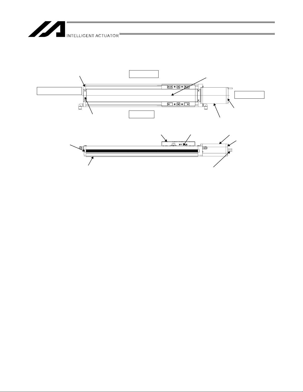
In this operating manual, the left and right sides are indicated by looking at the actuator from the motor end, with
the actuator placed horizontally, as shown in the figure below.
1. ISDB/ISPDB
Side cover
Front cover
Right side (R)
Stainless sheet
Coupling cover
Actuator cable
Front side
Sheet cover plate
Front cover
2. ISDBCR/ISPDBCR
Left side (L)
Side cover
Side cover
Right side (R)
Base
Slider
Slider cover
Stainless sheet
Motor side
Rear cover
Motor cover
Grease nipple
Motor cover
Rear cover
Plug screw
Actuator cable
Coupling cover
Actuator cable
Front side
Sheet cover plate
Front cover
Left side (L)
Side cover
Base
Slider
Air tube
Air tube
Slider cover
Grease nipple
Air piping joint
Motor side
Rear cover
Motor cover
Motor cover
Rear cover
Actuator cable
9
Page 18
3. SSPDACR
Front cover
Front side
Front cover
Sheet cover plate
Base
Right side
Left side
Slider
Stainless sheet
Grease nipple
Actuator cable
Motor side
Rear cover
Motor cover
Motor cover
Rear cover
10
Page 19

1. Checking the Product
If based on a standard configuration, this product consists of the items listed below.
Caution: Check the packed items against the packing specification. Should you find a wrong model or any
missing item, please contact your IAI dealer or IAI.
1.1 Components
No. Name Model number Remarks
1 Actuator
Accessories
2 Motor/encoder cables*
3 Home making seals
4 Quick Step Guide
5 Operation Manual (CD/DVD)
6 Safety Guide
*1 The motor/encoder cables supplied vary depending on the controller used. [Refer to 11, “Motor/Encoder
Cables”.]
1
Refer to “How to Read the Model Nameplate” and
“How to Read the Model Number.”
1.2 Related Operation Manuals for Each Controller Supported by This Product
1. Checking the Product
The table below lists the related operation manuals for each controller supported by this product, which are
included in the Operation Manual CD/DVD.
(1) XSEL-J/K controllers
No. Name Control No.
1 Operation Manual for XSEL-J/K Controller ME0116
2 Operation Manual for PC Software IA-101-X-MW/IA-101-X-USBMW ME0154
3 Operation Manual for Teaching Pendant SEL-T/TD/TG ME0183
4 Operation Manual for Teaching Pendant IA-T-X/XD ME0160
5 Operation Manual for DeviceNet ME0124
6 Operation Manual for CC-Link ME0123
7 Operation Manual for PROFIBUS ME0153
8 Operation Manual for X-SEL Ethernet ME0140
9 Operation Manual for Multi-point I/O Board ME0138
10 Operation Manual for Dedicated Multi-point I/O Board Terminal Block ME0139
11
Page 20

(2) XSEL-P/Q controllers
r
r
No. Name Control No.
1 Operation Manual for XSEL-P/Q Controller ME0148
2 Operation Manual for XSEL-P/Q/PX/QX RC Gateway Function ME0188
3 Operation Manual for PC Software IA-101-X-MW/IA-101-X-USBMW ME0154
4 Operation Manual for Teaching Pendant SEL-T/TD/TG ME0183
5 Operation Manual for Teaching Pendant IA-T-X/XD ME0160
6 Operation Manual for DeviceNet ME0124
7 Operation Manual for CC-Link ME0123
8 Operation Manual for PROFIBUS ME0153
1. Checking the Product
(3) SSEL controllers
No. Name Control No.
1 Operation Manual for SSEL Controller ME0157
2 Operation Manual for PC Software IA-101-X-MW/IA-101-X-USBMW ME0154
3 Operation Manual for Teaching Pendant SEL-T/TD/TG ME0183
4 Operation Manual for Teaching Pendant IA-T-X/XD ME0160
5 Operation Manual for DeviceNet ME0124
6 Operation Manual for CC-Link ME0123
7 Operation Manual for PROFIBUS ME0153
(4) SCON controllers
No. Name Control No.
1 Operation Manual for SCON Controller ME0161
2 Operation Manual for SCON-CA Controller ME0155
3 Operation Manual for PC Software RCM-101-MW/RCM-101-USB ME0243
4 Operation Manual for Teaching Pendant CON-T/TG ME0178
5 Operation Manual for Touch Panel Teaching Pendant CON-PT/PD/PG ME0227
6 Operation Manual for Simple Teaching Pendant RCM-E ME0174
7 Operation Manual for Data Setter RCM-P ME0175
8 Operation Manual for Touch Panel Display RCM-PM-01 ME0182
9 Operation Manual for DeviceNet ME0124
10 Operation Manual for CC-Link ME0123
11 Operation Manual for PROFIBUS ME0153
1.3 How to Read the Model Nameplate
Model numbe
Serial numbe
MODEL ISDBMA20020500T2MB
SERIAL No.100061911 MADE IN JAPAN
12
Page 21

1.4 How to Read the Model Number
ISDB - M - A - 200 - 20 - 500 – T2 - M - B - **
<Series>
Simple dust-proof type
Aluminum-based
ISDB: Standard specification
ISPDB: High-precision
specification
Clean room type
Aluminum-based
ISDBCR: Standard specification
ISPDBCR: High-precision
specification
Iron-based
SSPDACR: High-precision
specification
<Type>
S: Small type
M: Medium type
MX: Medium type with intermediate
support
L: Large type
LX: Large type with intermediate
support
<Encoder type>
A: Absolute
I: Incremental
<Motor type>
60: 60 W
100: 100 W
200: 200 W
400: 400 W
Identification for IAI use only
<Options>
AQ : AQ seal (Standard equipment)
B : Brake
C : Creep sensor
L : Limit switch
LL : Limit switch, opposite side
LM : Synchronized specification, master axis
LLM : Synchronized specification
(sensor on opposite side, master axis)
NM : Reversed-home specification
RT : Guide with ball retention mechanism
S : Synchronized specification, slave axis
A1S : Cable exit from the left
A1E : Cable exit from the back on the left
A3S : Cable exit from the right
A3E : Cable exit from the back on the right
ST : High-precision straightness specification
(Note) Option only for High-Precision
Types (ISPDB, ISPDBCR and
SSPDACR)
VR : Piping joint for suction
Opposite installation specification
<Cable length>
N: No cable
S: 3 m
M: 5 m
X: Length specification
*1
1. Checking the Product
<Lead>
4: 4 mm
5: 5 mm
8: 8 mm
10: 10 mm
16: 16 mm
20: 20 mm
30: 30 mm
40: 40 mm
*1 This maybe displayed for the manufacturing reason.
(This is not to indicate the manufacturing model code.)
<Applicable controller>
T1: XSEL-J/K
T2: SCON
SSEL
XSEL-P/Q
<Stroke>
13
Page 22

2. Specification
2.1 Maximum Speed
(1) ISDB, ISPDB, ISDBCR, ISPDBCR
The maximum speed of the actuator is limited to prevent resonance of the ball screw shaft that may occur beyond
a certain motor speed.
Be sure to observe the applicable maximum speed shown in the table below.
Strokes and maximum speed limits (Unit: mm/s)
2. Specication
Size
S 60
Size
M
Size
MX 200
Size
L
Motor
capacity (W))
Motor
capacity (W))
100
200
Motor
capacity (W))
Motor
capacity (W))
200
400
Lead
(mm)
100 150 200 250 300 350 400 450 500 550 600 650 700 750 800 850 900 950 1000 1050 1100
4 240 230 200 170 150 135 120
8 480 460 400 345 305 270 240
16 960 920 795 690 610 540 480
Lead
(mm)
100 150 200 250 300 350 400 450 500 550 600 650 700 750 800 850 900 950 1000 1050 1100
5 300 270 240 215 190 170 155 140 130 120 110
10 600 545 480 430 380 345 310 285 260 240 220
20 1200 1085 960 855 765 690 625 570 520 475 440
30 1800 1630 1440 1280 1150 1035 935 850 780 715 660
5 300 270 240 215 190 170 155 140 130 120 110
10 600 545 480 430 380 345 310 285 260 240 220
20 1200 1085 960 855 765 690 625 570 520 475 440
30 1800 1630 1440 1280 1150 1035 935 850 780 715 660
300
350
Stroke [mm]
400
500
450
550
600
700 750 800 850 900 950 1000 1050 1100 1150 1200 1250 1300
650
Lead
(mm)
800 900 1000 1100 1200 1300 1400 1500 1600
20 1200 1100 1000 950 800 700
30 1800 1650 1500 1425 1200 1050
Lead
100
150
200
250
(mm)
10 600 585 520 470 425 385 350 320 295 275 255 235 220 205
20 1200 1165 1045 940 850 770 705 645 595 545 505 470 440 410
40 1800 1700 1540 1410 1290 1185 1095 1015 940 875 815
10 600 585 520 470 425 385 350 320 295 275 255 235 220 205
20 1200 1165 1045 940 850 770 705 645 595 545 505 470 440 410
40 1800 1700 1540 1410 1290 1185 1095 1015 940 875 815
Stroke [mm]
Stroke [mm]
Stroke [mm]
14
Size
LX
Motor
capacity (W))
200
400
Lead
(mm)
1000 1100 1200 1300 1400 1500 1600
20 1200 1150 1000 950 830
40 1800 1660
20 1200 1150 1000 950 830
40 1800 1660
Stroke [mm]
Page 23

(2) SSPDACR
The maximum speed of the actuator is limited to prevent resonance of the ball screw shaft that may occur beyond
a certain motor speed.
Be sure to observe the applicable maximum speed shown in the table below.
Stroke and maximum speed (or speed to reach) limits (Unit: mm/s)
Size
capacity
S 200
M 400
L
Motor
Lead
[mm]
[W]
750 25
750 50
100 150 200 250 300 350 400 450 500 550 600 650 700 750 800 850 900 950 1000 1050 1100 1150 1200 1250 1300 1350 1400 1450 1500
10 600 540 480 430 380 340 310 280 260 240 220 200 - - - - - - - 20 1100 1090 970 880 770 690 630 570 520 480 440 400 - - - - - - - 30 1600 1450 1290 1160 1040 940 860 780 720 660 610 - - - - - - - 10 600 580 520 470 420 380 350 320 290 270 250 230 220 200 190 - - - 20 1100 1040 940 850 770 700 640 590 550 500 470 440 410 380 - - - 40 1600 1540 1410 1290 1180 1100 1010 940 880 820 760 - - - -
1080 1100 1060 900 770 670 580 520
620 880 1080 1100 1060 900 770 670 580 520
1080 1530 1600 1550 1340 1170 1040
620 880 1080 1250 1400 1530 1600 1550 1340 1170 1040
Stroke [mm]
Caution:
(1) Do not set speeds and accelerations/decelerations equal to or greater than the respective ratings.
Doing so may result in vibration, failure or shorter life.
(2) In the case of interpolated operation of two or more orthogonal axes, make sure the command values
(settings) of speed and acceleration/deceleration do not exceed the smallest values of all speeds and
accelerations/decelerations of the applicable axes.
Even if any speed or acceleration/deceleration is set that exceeds the smallest speed or
acceleration/deceleration among all applicable axes, the actual speed or acceleration/deceleration will
be clamped to the smallest speed or acceleration/deceleration.
(3) If any acceleration/deceleration equal to or greater than the rated acceleration/deceleration is set, a
creep phenomenon or slipped coupling may occur.
2. Specication
15
Page 24

2.2 Acceleration/Deceleration, Payload Capacity and Rated Thrust
If the payload capacity is smaller than as specified, the acceleration/deceleration can be raised beyond the
applicable level.
(1) ISDB, ISPDB, ISDBCR, ISPDBCR
Type Size
2. Specication
Guide with ball retention mechanism (RT) not used
Motor capacity
[W]
S 60
100
M
200
MX 200
200
L
400
200
LX
400
Lead [mm]
4
8
16
5
10
20
30
5
10
20
30
20
30
10
20
40
10
20
40
20
40
20
40
Rated
acceleration/
deceleration [G]
0.2 0.5 Horizontal 55 50 38 30 - - - - -
0.2 0.4 Vertical 14 13 12 - - - - - -
0.4 0.7 Horizontal 27 27 27 20 15 12 - - -
0.4 0.6 Vertical 6 6 6 5.5 5 - - - -
0.4 1.0 Horizontal 13 13 13 10.5 8.5 7 6 5.5 4.5
0.4 0.8 Vertical 3 3 3 2.8 2.5 2.3 2 - -
0.2 0.5 Horizontal 85 80 60 45 - - - - -
0.2 0.4 Vertical 20 17 15 - - - - - -
0.4 0.7 Horizontal 45 45 45 30 23 20 - - -
0.4 0.6 Vertical 10 10 10 8 7 - - - -
0.4 1.0 Horizontal 23 23 23 18 15 13 11 9 8
0.4 1.0 Vertical 4 4 4 3.8 3.5 3.3 3 2.8 2.5
0.4 1.0 Horizontal 15 15 15 11 9 7 6 5 4
0.4 1.0 Vertical 2 2 2 1.8 1.6 1.5 1.4 1.3 1.2
0.2 0.5 Horizontal 110 100 90 80 - - - - -
0.2 0.4 Vertical 40 34 30 - - - - - -
0.4 0.7 Horizontal 90 90 90 66 51 40 - - -
0.4 0.6 Vertical 20 20 20 17 15 - - - -
0.4 1.0 Horizontal 45 45 45 35 28 23 20 18 16
0.4 1.0 Vertical 10 10 10 8.5 7.5 7 6 5.5 5
0.4 1.0 Horizontal 30 30 30 24 20 17 15 13 12
0.4 1.0 Vertical 6 6 6 5.5 5 4.5 4 3.5 3
0.4 0.4 Horizontal 45 45 45 - - - - - -
- - Vertical - - - - - - - - -
0.4 0.4 Horizontal 30 30 30 - - - - - -
- - Vertical - - - - - - - - -
0.4 0.7 Horizontal 90 90 90 66 51 40 - - -
0.4 06 Vertical 20 20 20 16 14 - - - -
0.4 1.0 Horizontal 45 45 45 35 28 23 20 17 15
0.4 1.0 Vertical 9 9 9 8.5 7.5 7 6 5.5 5
0.4 1.0 Horizontal 15 15 15 12 10.5 9 8 7.5 7
0.4 1.0 Vertical 2.5 2.5 2.5 2.4 2.3 2.2 2.1 2 2
0.4 0.7 Horizontal 120 120 120 92 73 60 - - -
0.4 0.6 Vertical 40 40 40 35 30 - - - -
0.4 1.0 Horizontal 90 90 90 70 57 47 40 35 30
0.4 1.0 Vertical 20 20 20 17 15 14 12 11 10
0.4 1.0 Horizontal 40 40 40 32 27 23 21 19 17
0.4 1.0 Vertical 8 8 8 7.5 7 6.5 6 5.5 5
0.4 0.4 Horizontal 45 45 45 - - - - - -
- - Vertical - - - - - - - - -
0.4 0.4 Horizontal 15 15 15 - - - - - -
- - Vertical - - - - - - - - -
0.4 0.4 Horizontal 90 90 90 - - - - - -
- - Vertical - - - - - - - - -
0.4 0.4 Horizontal 40 40 40 - - - - - -
- - Vertical - - - - - - - - -
Maximum
acceleration/d
eceleration [G]
Horizontal
Vertical
Payload capacity by acceleration/deceleration [kg]
0.2G 0.3G 0.4G 0.5G 0.6G 0.7G 0.8G 0.9G 1.0G
Rated
thrust
[N]
212.3
106.1
53.1
339.7
169.8
89.9
56.6
683.6
341.8
170.9
113.9
170.9
113.9
341.8
170.9
85.5
678.3
339.1
169.9
170.9
85.5
339.1
169.9
Caution: Even when the acceleration/deceleration is less than the rated acceleration/deceleration, the
payload capacity will not exceed the specified payload capacity at the rated
acceleration/deceleration.
16
Page 25

Type Size
S 60
M
MX 200
L
Guide with ball retention mechanism (RT) used
LX
Motor
capacity [W]
100
200
200
400
200
400
Lead [mm]
4
8
16
5
10
20
30
5
10
20
30
20
30
10
20
40
10
20
40
20
40
20
40
Rated
acceleration/
deceleration [G]
0.2 0.5 Horizontal 55 50 38 30 - - - - -
0.2 0.4 Vertical 13.5 12.5 11.5 - - - - - -
0.4 0.7 Horizontal 27 27 27 20 15 12 - - -
0.4 0.6 Vertical 5.5 5.5 5.5 5.0 4.5 - - - -
0.4 1.0 Horizontal 13 13 13 10.5 8.5 7 6 5.5 4.5
0.4 0.8 Vertical 2.5 2.5 2.5 2.3 2.0 1.8 1.5 - -
0.2 0.5 Horizontal 85 80 60 45 - - - - -
0.2 0.4 Vertical 19.5 16.5 14.5 - - - - - -
0.4 0.7 Horizontal 45 45 45 30 23 20 - - -
0.4 0.6 Vertical 9.5 9.5 9.5 7.5 6.5 - - - -
0.4 1.0 Horizontal 23 23 23 18 15 13 11 9 8
0.4 1.0 Vertical 3.5 3.5 3.5 3.3 3.0 2.8 2.5 2.3 2.0
0.4 1.0 Horizontal 15 15 15 11 9 7 6 5 4
0.4 1.0 Vertical 1.5 1.5 1.5 1.3 1.1 1.0 0.9 0.8 0.7
0.2 0.5 Horizontal 110 100 90 80 - - - - -
0.2 0.4 Vertical 40 34 30 - - - - - -
0.4 0.7 Horizontal 90 90 90 66 51 40 - - -
0.4 0.6 Vertical 20 20 20 17 15 - - - -
0.4 1.0 Horizontal 45 45 45 35 28 23 20 18 16
0.4 1.0 Vertical 10 10 10 8.5 7.5 7 6 5.5 5
0.4 1.0 Horizontal 30 30 30 24 20 17 15 13 12
0.4 1.0 Vertical 6 6 6 5.5 5 4.5 4 3.5 3
0.4 0.4 Horizontal 45 45 45 - - - - - -
- - Vertical - - - - - - - - -
0.4 0.4 Horizontal 30 30 30 - - - - - -
- - Vertical - - - - - - - - -
0.4 0.7 Horizontal 90 90 90 66 51 40 - - -
0.4 06 Vertical 19 19 19 15 13 - - - -
0.4 1.0 Horizontal 45 45 45 35 28 23 20 17 15
0.4 1.0 Vertical 8 8 8 7.5 6.5 6 5 4.5 4
0.4 1.0 Horizontal 15 15 15 12 10.5 9 8 7.5 7
0.4 1.0 Vertical 1.5 1.5 1.5 1.4 1.3 1.2 1.1 1 1
0.4 0.7 Horizontal 120 120 120 92 73 60 - - -
0.4 0.6 Vertical 40 40 40 35 30 - - - -
0.4 1.0 Horizontal 90 90 90 70 57 47 40 35 30
0.4 1.0 Vertical 20 20 20 17 15 14 12 11 10
0.4 1.0 Horizontal 40 40 40 32 27 23 21 19 17
0.4 1.0 Vertical 8 8 8 7.5 7 6.5 6 5.5 5
0.4 0.4 Horizontal 45 45 45 - - - - - -
- - Vertical - - - - - - - - -
0.4 0.4 Horizontal 15 15 15 - - - - - -
- - Vertical - - - - - - - - -
0.4 0.4 Horizontal 90 90 90 - - - - - -
- - Vertical - - - - - - - - -
0.4 0.4 Horizontal 40 40 40 - - - - - -
- - Vertical - - - - - - - - -
Maximum
acceleration/d
eceleration
[G]
Horizontal
Vertical
Payload capacity by acceleration/deceleration [kg]
0.2G 0.3G 0.4G 0.5G 0.6G 0.7G 0.8G 0.9G 1.0G
Rated
thrust
[N]
212.3
106.1
53.1
339.7
169.8
84.9
56.6
683.6
341.8
170.9
113.9
170.9
113.9
341.8
170.9
85.5
678.3
339.1
169.9
170.9
85.5
339.1
169.9
2. Specication
Caution: Even when the acceleration/deceleration is less than the rated acceleration/deceleration, the
payload capacity will not exceed the specified payload capacity at the rated
acceleration/deceleration.
17
Page 26

(2) SSPDACR
Size Type
S - 200
M - 400
2. Specication
Guide with ball
mechanism (RT)
L
Guide with ball
mechanism (RT)
Caution: Even when the acceleration/deceleration is less than the rated acceleration/deceleration, the
Payload capacity by acceleration/deceleration [kg]
retention
not used
retention
used
Motor
capacity
[W]
750
750
Lead
[mm]
0.4 0.7 Horizontal 90 90 90 72 60 50 - - - - -
0.4 0.6 Vertical 12 12 12 10 8 - - - - - -
0.4 1.2 Horizontal 45 45 45 36 30 26 22.5 19.5 17 - -
0.4 1.2 Vertical 6 6 6 4.8 4 3.4 3 2.7 2.4 - -
0.4 1.2 Horizontal 30 30 30 24 20 17 15 13 12 11 10
0.4 1.2 Vertical 4 4 4 3.2 2.7 2.3 2 1.7 1.4 1.2 1
0.4 0.7 Horizontal 120 120 120 96 80 70 - - - - -
0.4 0.6 Vertical 25 25 25 20 16.5 - - - - - -
0.4 1.2 Horizontal 90 90 90 72 60 51 45 39 34 - -
0.4 1.2 Vertical 12 12 12 9.6 8 6.9 6 5.3 4.8 - -
0.4 1.2 Horizontal 45 45 45 36 30 25.5 22.5 19.5 17 15 13.5
0.4 1.2 Vertical 6 6 6 4.8 4 3.4 3 2.7 2.4 2.2 2
25 1.2
50 1.2
25 1.2
50 1.2
Maximum
acceleration/
deceleration [G]
Horizontal
Vertical
Horizontal - - 120 96 80 69 60 53 48 44 40
Vertical - - 25 20 17 14 13 11 10 9 8
Horizontal - - 60 48 40 34 30 27 24 22 20
Vertical - - 12 10 8 7 6 5 5 4 4
Horizontal - - 120 96 80 69 60 53 48 44 40
Vertical - - 23 18 15 12 11 9 8 7 6
Horizontal - - 60 48 40 34 30 27 24 22 20
Vertical - - 10 8 6 5 4 3 3 2 2
0.2G 0.3G 0.4G 0.5G 0.6G 0.7G 0.8G 0.9G 1.0G 1.1G 1.2G
payload capacity will not exceed the specified payload capacity at the rated
acceleration/deceleration.
Rated
thrust
[N]
341.8
170.9
113.9
678.3
339.1
169.6
510
255
510
255
18
Page 27

2.3 Driving System/Position Detector
The actuator is driven by the AC servo control method.
(1) ISDB, ISPDB, ISDBCR, ISPDBCR
Size
Motor capacity
[W]
Lead
[mm]
4
S 60
8
16
5
100
M
200
10
20
30
5
10
20
30
MX 200
20
30
10
200
L
400
20
40
10
20
40
200
LX
400
20
40
20
40
*1 Number of pulses input to the controller.
Encoder
*1
pulses
16384
Ball screw specification
Type Diameter ISD series ISPD series
Rolled
Rolled
Rolled
Rolled
Rolled
Rolled
Rolled
Rolled
12 mm
16 mm
16 mm
16 mm
20 mm
20 mm
20 mm
20 mm
C10
C10
C10
C10
C10
C10
C10
C10
C5 or
equivalent
C5 or
equivalent
C5 or
equivalent
C5 or
equivalent
C5 or
equivalent
C5 or
equivalent
C5 or
equivalent
C5 or
equivalent
2. Specication
(2) SSPDACR
Size
Motor capacity
[W]
Lead
[mm]
10
S 200
20
30
10
M 400
20
40
L 750
25
50
*1 Number of pulses input to the controller.
Encoder
*1
pulses
16384
Ball screw specification
Type Diameter SSPDACR
Rolled
Rolled
Rolled
16 mm
20 mm
25 mm
C5 or
equivalent
C5 or
equivalent
C5 or
equivalent
19
Page 28

2.4 Positioning Preciseness
Positioning repeatability
*1 Initial value
2. Specication
Item
Backlash*1 0.05 mm or less 0.02 mm or less 0.02 mm or less
ISD ISPD SSPDACR
r0.01 mm r0.005 mm r0.005 mm
Functions
20
Page 29

2.5 Allowable Load Moment of the Actuator
(1) ISDB, ISPDB, ISDBCR, ISPDBCR
Size
Allowable load moment (Nxm) Allowable load moment (Nxm)
Ma Ma Mb Mc Mb Mc
S 143.8 205.4 336.0 28.4 40.2 65.7
M 341.5 487.0 796.5 69.6 99.0 161.7
MX 341.5 487.0 796.5 69.6 99.0 161.7
L 560.2 800.1 1325.3 104.9 149.9 248.9
LX 560.2 800.1 1325.3 104.9 149.9 248.9
Mb direction
Mb or Mc direction
L
Direction of allowable overhang
Mc direction
Ma direction
Direction of moment
Allowable overhang load (L)
Ma direction: 450
Mb or Mc direction: 450
Ma direction: 600
Mb or Mc direction: 600
Ma direction: 600
Mb or Mc direction: 600
Ma direction: 750
Mb or Mc direction: 750
Ma direction: 750
Mb or Mc direction: 750
Ma direction
L
2. Specication
Reference position for
moment calculation
L mm
Reference position
Size
S 42.5
[mm]
L [mm]
M 51.5
MX 51.5
L 61.5
LX 61.5
Caution: Make sure the load installed on the actuator is not longer than the allowable overhang load length
(L). If the load is longer than L, vibration may occur or the settling time may increase depending on
the position of center of gravity position or weight of the work part.
If a load moment exceeding the allowable load moment is applied, not only the life of the guide will
become shorter but vibration or longer settling time may also result.
21
Page 30

(2) SSPDACR
Size
S 190 190 530 36 36 98
M 470 470 1210 90 90 230
L 750 750 1850 138.8 138.8 334.5
2. Specication
Mc direction
Static allowable load moment
[Nxm]
Dynamic allowable load moment
[Nxm]
Ma Mb Mc Ma Mb Mc
Mb direction
Ma direction
Direction of moment
Mb or Mc direction
Direction of allowable overhang
Ma direction
Allowable overhang
load [L]
Ma direction: 450
Mb or Mc direction: 450
Ma direction: 600
Mb or Mc direction: 600
Ma direction: 750
Mb or Mc direction: 750
Reference position for
moment calculation
L [mm]
S 50
L
Reference position
M 58.5
L 65.5
Caution: Make sure the load installed on the actuator is not longer than the allowable overhang load length
(L). If the load is longer than L, vibration may occur or the settling time may increase depending on
the position of center of gravity position or weight of the work part.
If a load moment exceeding the allowable load moment is applied, not only the life of the guide will
become shorter but vibration or longer settling time may also result.
22
Page 31

3. Life
The mechanical life of an actuator is represented by the life of its guide that receives the largest moment load.
The “rated load” is one factor that relates to the traveling life.
There are two types of “rated load,” namely “static rated load” and “dynamic rated load.”
x “Static rated load”: Load which, when applied to a stationary actuator, leaves a minor pressure mark on
the contract surface.
x “Dynamic rated load”: Load which applies after a specified traveling distance under a load based on a
specific probability of survival at which the guide does not break
Guide manufacturers indicate the life of a guide using a dynamic rated load when the provability of survival after
50 km of traveling is 90%.
In the case of general industrial machinery, however, you must know the specific life for the purpose of
maintenance. Also, the life of a guide has a sufficient allowance relative to a radial load, and receives the greatest
impact by a moment load offset from the center of the guide.
The life of the IS series corresponds to a traveling life of 10000 km at a load factor of 1.2 (safety factor) when the
allowable load moment is applied. [For the dynamic allowable load moment, refer to 2, “Specification”]
The calculation formula for allowable load moment at a traveling life of 10,000 km is shown below:
C
: Allowable load moment
IA
fW: Load coefficient (= 1.2)
M50: Dynamic rated moment when the probability of survival after 50
km of traveling is 50%
The life at the actual moment is calculated by the formula below:
3. Life
L: Traveling live (probability of survival: 90%)
C
: Allowable dynamic moment
IA
P: Actual moment
23
Page 32

4. Installation and Storage/Preservation Environment
4.1 Installation Environment
The actuator should be installed in a location other than those specified below.
In general, the installation environment should be one in which an operator can work without protective gear.
Also provide sufficient work space required for maintenance inspection.
x Where the actuator receives radiant heat from strong heat sources such as heat treatment furnaces
x Where the ambient temperature exceeds the range of 0 to 40qC
x Where the temperature changes rapidly and condensation occurs
x Where the relative humidity exceeds 85% RH
x Where the actuator receives direct sunlight
x Where the actuator is exposed to corrosive or combustible gases
x Where the ambient air contains a large amount of powder dust, salt or iron (at level exceeding what is normally
expected in an assembly plant)
x Where the actuator is subject to splashed water, oil (including oil mist or cutting fluid) or chemical solutions
x Where the actuator receives impact or vibration
If the actuator is used in any of the following locations, provide sufficient shielding measures:
x Where noise generates due to static electricity, etc.
x Where the actuator is subject to a strong electric or magnetic field
x Where the actuator is subject to ultraviolet ray or radiation
4.2 Storage/Preservation Environment
The storage/preservation environment should be similar to the installation environment. In addition, make sure
condensation will not occur when the actuator is to be stored or preserved for a long period of time. Unless
specified, we do not include drying agents when shipping the actuator. If you are storing the actuator in an
4. Installation and Storage/Preservation Environment
environment where condensation might occur, you must treat the entire shipping box, or treat the actuator itself
after unpacking, to prevent condensation. The unit can withstand temperatures up to 60ºC during a short
storage/preservation period, but only up to 50ºC if the storage/preservation period is longer than one month.
The actuator should be lying flat during storage/preservation.
If the actuator is to be stored in a packed state, follow the specified actuator position if indicated.
24
Page 33

5. Transport
5.1 Handling a Single Axis
5.1.1 Handling a Package
Unless otherwise specified, each axis is packed and shipped individually.
x Do not bump or drop the package. The package is not specially designed to withstand the impact of dropping
or bumping.
x An operator must not attempt to carry a heavy package alone. Transport the package using an appropriate
transport means.
x If the shipping box is to be left standing or transported, it should be in a horizontal position. If the packing
specification is instructed, follow the instruction.
x Do not step onto the package.
x Do not put any article on the package which may deform or damage the package.
5.1.2 Handling an Actuator after Unpacking
(1) ISDB, ISPDB, ISDBCR, ISPDBCR
x Do not transport the actuator by holding the cable or move it by pulling the cable.
x When transporting the actuator, hold its base.
x When transporting the actuator, be careful not to bump the actuator against anything.
x Do not apply excessive force on any part of the actuator.
x In the case of the high-precision straightness specification type, be careful not to make a damage and the
traces of hitting at the base bottom.
There is a possibility that the running accuracy changes.
5. Transport
25
Page 34

5. Transport
(2) SSPDACR
x Four eye bolts are installed, so use these bolts to transport the actuator. The SSPDACR, when unpacked,
looks like the condition shown in the figure below.
Motor cover
M8 eye bolt
x Do not hold the motor cover when transporting the SSPDACR. Doing so may damage the cover due to the
weight of the actuator or the main unit may fall.
x Do not transport the actuator by holding the cable, or move it by pulling the cable.
x Be careful not to bump the actuator against anything when transporting it.
x Do not apply excessive force on any of the actuator parts.
x In the case of the high-precision straightness specification type, be careful not to make a damage and the
traces of hitting at the base bottom.
There is a possibility that the running accuracy changes.
26
Page 35

5.2 Handling an Cartesian Robot (ICS)
Take note of the following points when transporting a set of axes that have been combined.
5.2.1 Handling a Package
Before shipment, combined axes are packed in an outer frame nailed to the base made of square lumbers. Each
slider is secured to prevent accidental movement during transport. Each actuator end is also secured to prevent
oscillating due to external vibration.
x Do not bump or drop the package. The package is not specially designed to withstand the impact of dropping
or bumping.
x An operator must not attempt to carry a heavy package alone. Transport the package using an appropriate
transport means.
x When hoisting the package using ropes, etc., support the square lumber base at the reinforcements at the
bottom. Similarly when lifting the package with a forklift, insert the forks at the bottom of the square lumber
base.
x When setting down the package, be careful not to let the package receive shock or bounce.
x Do not step onto the package.
x Do not put any article on the package which may deform or damage the package.
5.2.2 Handling an Actuator after Unpacking
5. Transport
x Secure the sliders to prevent sudden movement during transport.
x If any end of the actuator is overhanging, secure it properly to avoid significant movement due to external
vibration.
x If the actuator assembly is transported without the ends being secured, do not apply an impact of 0.3 G or
more.
x When hoisting the actuator using ropes, etc., use appropriate cushioning materials to protect the actuator
against strain or distortion. Also keep a stable, horizontal orientation. If necessary, use the tapped mounting
holes provided on the bottom face of the base to install hoisting jigs.
x Be careful not to apply a load on any of the actuator brackets or covers or on the connector box. Also, do not
allow the cable to be pinched or deformed excessively.
27
Page 36

5. Transport
5.3 Handling an Actuator Assembled to a Mechanical System
When transporting an actuator that has been assembled to a mechanical system, as the whole system, take note
of the following points:
x Secure the sliders to prevent sudden movement during transport.
x If any end of the actuator is overhanging, secure it properly to avoid significant movement due to external
vibration.
x If the actuator assembly is transported without the ends being secured, do not apply an impact of 0.3 G or
more.
x When hoisting the mechanical system using ropes, etc., prevent the actuator, connector box, etc., from
receiving a load. Also make sure the cables are not pinched or deformed unnaturally.
28
Page 37

6. Installation
6.1 Installation Orientations
Actuators are subject to certain limitations regarding their installation orientations.
If an actuator is installed in an orientation not allowed for that actuator, the stainless sheet may break or other
problems may occur.
{: Installable U: Daily inspection is required x: Not possible
S
M
L
Type
ISDB
ISPDB
ISDBCR
ISPDBCR
SSPDACR
ISDB
ISPDB
ISDBCR
ISPDBCR
SSPDACR
MX
ISDB
ISPDB
ISDBCR
ISPDBCR
SSPDACR
LX
Horizontal
installation
{ {
{ {
{ {
{ {
{
{ {
{ {
{
Vertical installation
X X X
X X X
Sideway
installation
U U
X X
U U
X X
U U
X X
Ceiling mount
installation
6. Installation
Installation oeientations
Horizontal Vertical Vertical Ceiling mount
29
Page 38

6. Installation
Caution: (1) When installing the actuator vertically, make sure the motor comes to the top. When the
actuator is installed with the motor at the bottom, there shouldn’t be any problems
during normal operations. If the actuator is not operated for an extended period of time,
however, depending on the ambient environment (especially at high temperature)
grease may separate and base oil may flow into the motor unit, causing problems on
rare occasions.
(2) ISDB, ISPDB, ISDBCR and ISPDBCR actuators of S, L and M types can be installed
sideways or ceiling mount, but the actuators must be checked daily. If the actuator is
installed sideways or ceiling mount, the stainless sheet may be slacked or displaced. If
the actuator is used continuously while the stainless sheet is slacked or displaced, the
stainless sheet may break or other problems may occur. Check the actuator daily and if
the stainless sheet is found slacked or displaced, make installation adjustment of the
stainless sheet. [Refer to 13, “Replacement/Adjustment Procedure for Stainless
Sheet.”]
30
Page 39

6.2 Installing the Actuator
6.2.1 Installation Method
x Use the threaded holes on the back of the base to install the actuator.
x ISDB and ISDBCR actuators of intermediate support type (MX/LX) are installed in the same way as the
corresponding actuators without intermediate support. However, be careful not to remove or get caught by
the wire rope for the intermediate support during installation.
x When positioning pins are used, use pins with an engagement tolerance of h7 or equivalent.
x Positioning can also be performed by pushing the reference surface on the side of the base. [Refer to 6.2.2,
“Preciseness of the Installation Surface.”]
x Use high-tension bolts conforming to ISO 10.9 or higher.
x When the threaded holes are used, determine the required thread length as specified below:
x ISDB, ISPDB, ISDBCR, ISPDBCR
Depth of threaded hole > Thread engagement length > Nominal thread size x 1.8
x SSPDACR
Depth of threaded hole > Thread engagement length > Nominal thread size
x If the through holes are used to install a SSPDACR actuator, provide the following effective engagement
length, whichever is applicable, for the female thread:
x If the female thread is made of steel, same as the nominal diameter
x If the female thread is made of aluminum, 1.8 times of nominal diameter
x If the bolt seating surface is aluminum, or the through holes are used to install a SSPDACR actuator, also
use high-tension bolts with dedicated washers. Failure to do so may cause the seating surface to buckle.
6. Installation
31
Page 40

z ISDB, ISPDB, ISDBCR, ISPDBCR
The installation method is shown by a section view.
Base: Aluminum alloy
Depth of
threaded hole
B
(A6063SS-T6 or equivalent)
with alumite treatment
6. Installation
Installation bolt
Threaded hole
diameter
Thread size C
Type
Pitch of threaded
holes
Pitch of threaded
holes A
C
A
Depth of
threaded hole B
S 70 mm 17 mm M6
M, MX 90 mm 20 mm M8
L, LX 120 mm 20 mm M8
Tightening torque
Bolt seating surface is steel Bolt seating surface is aluminum
M6 12.3 Nxm 5.4 Nxm
M8 30.0 Nxm 11.5 Nxm
Bolt seating surface
Bolt
Seating surface Seating surface
Warning: The threaded holes are not through, so exercise caution when selecting the bolt length. Use of
inappropriate bolts may damage the threaded holes or result in insufficient mounting strength of the
actuator, leading to a lower precision or unexpected accident.
32
Page 41

z SSPDACR
The installation method is shown by a section view.
Threaded hole
Type Thread size Depth of threaded hole
S M6 9 mm
M M8 12 mm
L M8 16 mm
Base: Cast iron, coated
6. Installation
(Note) The through holes are lidded for keep the cleanliness.
It is not possible to attach with the screws applied from the actuator body side.
33
Page 42

[Threaded hole]
Installation bolt
[When threaded holes are used]
6. Installation
Seating surface Seating surface
Tightening torque
Bolt seating surface is steel Bolt seating surface is aluminum
M6 12.3 Nxm 5.4 Nxm
M8 30.0 Nxm 11.5 Nxm
Bolt
Warning: The threaded holes are not through, so exercise caution when selecting the bolt length. Use of
inappropriate bolts may damage the threaded holes or result in insufficient mounting strength of the
actuator, leading to a lower precision or unexpected accident.
34
Page 43
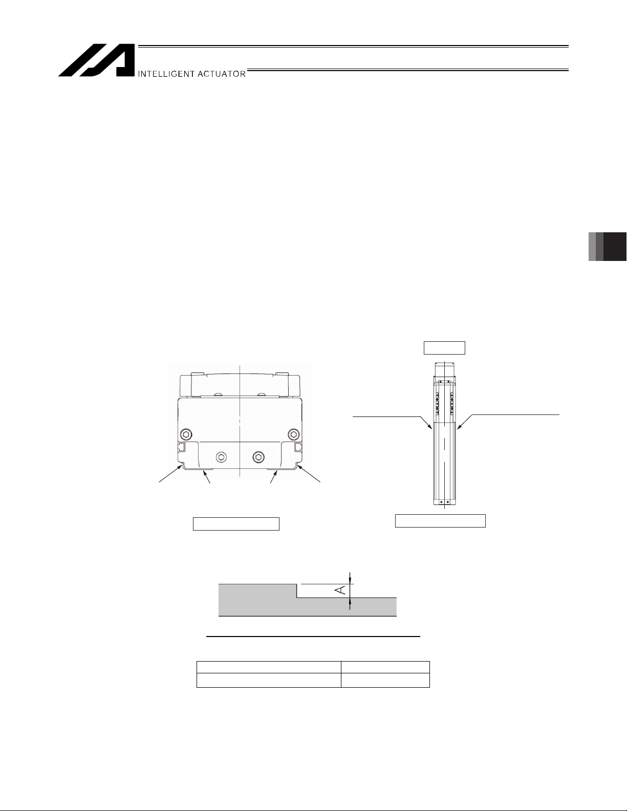
6.2.2 Preciseness of the Installation Surface
x The frame on which the actuator is installed shall have sufficient structural rigidity to remain free from
vibration, etc.
x The basis of measurement of the running accuracy of the slider is from the lower side and motor side to
right side.
If accuracy for its run is required, use these surfaces as a datum of the installation.
In view of the motor side, the parallelism of the quasi-reference surface of left side to the reference surface
is 0.1mm or less.
x The actuator installation surface shall be a flat surface that has been machined or has equivalent precision,
where the specific flatness of the installation surface shall be within 0.05 mm. If the installation surface is
rough, abnormal noise or other problems may occur due to poor contact of the actuator.
x If the actuator is of straightness high-precision specification (indicated by the option model number “ST”),
clean the base surface of any soiling and install the actuator on a flat surface with a preciseness of
0.02 mm in flatness.
[For the straightness high-precision specification (indicated by the option model number “ST”), refer to 10.9,
“High-Precision Straightness Specification.”]
x Provide enough space needed to carry out maintenance work.
z ISDB, ISPDB, ISDBCR, ISDBCR
Motor side
6. Installation
Reference surface
Base reference surface (side) Base reference surface (bottom) Quasi-reference surface
View from the front side
View from the upper side
Quasi-reference surface
x If the reference surface (side) of the base is used, provide a stopper part of the dimension shown below.
Dimension of stopper part on reference surface
Type Dimension A
Base reference surface (side) 3 to 5
35
Page 44

z SSPDACR
Slider reference surface (side)
Right side as viewed from the motor
Motor side
Slider reference surface (top)
6. Installation
x If the base reference surface (side) is used, provide a stopper part of the dimension shown below.
Reference surface (side)
Right side as viewed from the motor
Reference surface (bottom)
Shoulder dimension on base/slider reference surface (side)
Size Reference surface A
M
Reference surface
Quasi-reference surface
View from the upper side
S
Slider reference surface (side) 1.5 to 3.5
Base reference surface (side) 3 to 5
Quasi-reference surface
Slider reference surface (side) 1.5 to 3.5
Base reference surface (side) 3 to 7.5
L
Slider reference surface (side) 1.5 to 3.5
Base reference surface (side) 3 to 8
36
Page 45
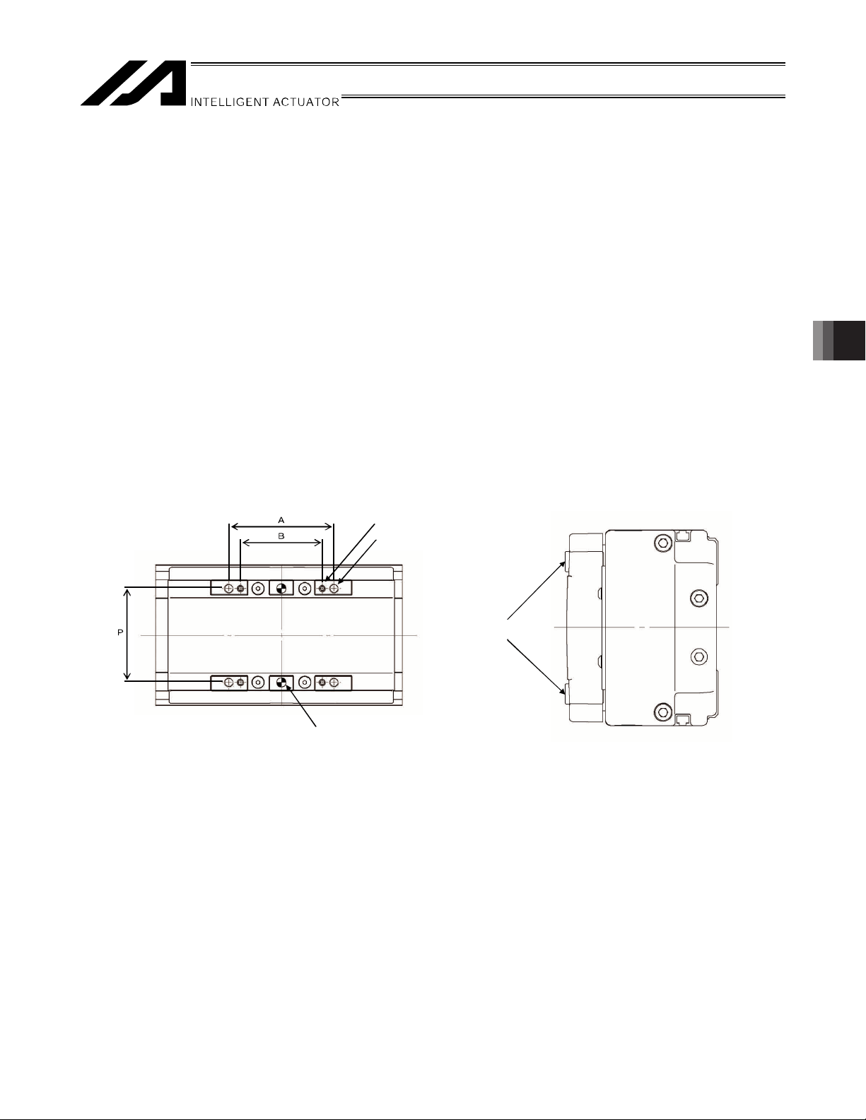
6.3 Installing the Load on the Slider
(
)
x The slider has two types of threaded holes, so affix the load using these holes. The affixing method shall
conform to the method for installing the actuator.
x Similarly when the slider is affixed and actuator is moved, install the slider using these threaded holes on
the slider.
x The slider has two reamed holes. If repeatability is required after removal/re-installation, use positioning
pins. If squareness is required, use one positioning pin and make installation adjustment.
x After removal/re-installation, repeatability can also be ensured by pushing the reference surface on the side
of the base.
x Use high-tension bolts conforming to ISO 10.9 or higher.
x When the threaded holes are used, determine the required thread length as specified below:
x ISDB, ISPDB, ISDBCR, ISPDBCR
Depth of threaded hole > Thread engagement length > Nominal thread size x 1.8
x SSPDACR
Depth of threaded hole > Thread engagement length > Nominal thread size
z ISDB, ISPDB, ISDBCR, ISPDBCR
Thread B
Thread A
6. Installation
Reamed hole C
C
Slider reference surface
top
37
Page 46

Work Installation Dimensions
ISDB-S, ISPDB-S/
ISDB-M, ISPDB-M/
ISDB-L, ISPDB-L/
6. Installation
Thread A Thread B Reamed hole C
Depth
[mm]
Dimension
A [mm]
Type
ISDBCR-S,
Hole
dimension P
[mm]
Thread
size
60 M6 19 70 - - -
ISPDBCR-S
ISDB-MX,
ISPDB-MX,
ISDBCR-M,
80
M8 18 90 M6 18 70
ISPDBCR-M
ISDBCR-MX,
ISPDBCR-MX
105
ISDB-LX,
ISPDB-LX,
ISDBCR-L,
105
M8 20 120 M8 20 90
ISPDBCR-L
ISDBCR-LX,
ISPDBCR-LX
Bolt size
Bolt seating surface is steel Bolt seating surface is aluminum
130
Tightening torque
M6 12.3 Nxm 5.4 Nxm
M8 30.0 Nxm 11.5 Nxm
Thread
size
Depth
[mm]
Dimension
B [mm]
Hole
diameter
6H7
8H7
8H7
Depth
[mm]
10
10
10
(Note) When positioning holes are used, use pins with an engagement tolerance of h7 or equivalent.
38
Page 47

z SSPDACR
Seating surface
Type Thread size Depth of threaded hole
S M6 9 mm
M M8 12 mm
L M8 16 mm
Seating surface
Bolt
Bolt seating surface
Seating surface
Seating surface
Bolt
6. Installation
Applicable bolt
Bolt seating surface is steel Bolt seating surface is aluminum
Tightening torque
M6 12.3 Nxm 5.4 Nxm
M8 30.0 Nxm 11.5 Nxm
(Note) When two positioning holes are used, use a h7 or equivalent pin for the reference hole and g6 pin for
the other hole.
39
Page 48

6.4 Using T-slots
M4 T-slots for installing the connector box, etc. are provided on the side face of the base, when configuring the
orthogonal axes. (See the figure below.)
You can also use these T-slots freely for installing sensors, securing wires or for other purposes as necessary.
6. Installation
4.5 1.5
3.4
3.7
Distance
from bolt end
Square nut
(or hexagonal nut)
Bolt
Installed
part
40
Page 49

6.5 Suctioning for Clean Room Application
Actuators designed for clean room application can demonstrate performance corresponding to cleanliness class
10 (0.1 Pm or more per 1 ft
3
) by suctioning air from the suction joint. The suction flow rate at the rated speed of
each model is shown in the table below.
Reference Suction Flow Rates
Type Thread lead
Suction flow rate
[NL/min]
4 15
ISDBCR-S
ISPDBCR-S
8 30
16 60
5 20
ISDBCR-M/MX
ISPDBCR-M/MX
10 50
20 120
30 180
10 50
ISDBCR-L/LX
ISPDBCR-L/LX
20 120
40 180
10 50
SSPDACR-S
20 100
30 150
10 60
SSPDACR-M
20 110
40 160
SSPDACR-L
25 120
50 180
6. Installation
x Suction air from the quick joint of 12 in outer diameter provided on the side face of the actuator. Connect an
air tube to this joint and suction air using a vacuum pump, ejector, etc. Suction equipment must be provided by
the customer.
41
Page 50

7. Connecting the Controller
7.1 Wiring
The actuator and controller are connected via the motor cable and encoder cable (genuine parts) using
connectors.
Motor cable
Controller
2)
%1&'
$-
2)
$-
/1&'
62
*156
Actuator
4$
219'4
(75'
Encoder cable
/ /
.5 .5
7. Connecting the Controller
[For details on extension cables, refer to 11, “Motor/Encoder Cables.”]
Example of connection with XSEL Controller
42
Page 51

When designing an application system, incorrect wiring or connection of each cable may cause unexpected
problems such as a disconnected cable or poor contact. The following explains examples of prohibited handling
of cables.
x Do not cut and reconnect the cable for extension or shorten the cable.
x Use a robot cable for any section where the cable will flex. [For the bending radius, refer to 11, “Motor/Encoder
Cable.”]
x Provide a sufficient bending radius and prevent the cable from bending at the same point.
Steel band
(piano wire)
Bundle loosely.
x Do not let the cable bend, kink or twist.
7. Connecting the Controller
x Do not pull the cable with a strong force
x Do not let the cable receive a turning force at a single point.
Use curl
codes
x Do not pinch, drop a heavy object onto or cut the cable
43
Page 52

x When fixing the cable, provide a moderate slack and do not tension it too tight.
x Separate the I/O and communication lines from the power and drive lines. Do not wire them together in the
same duct.
Follow the instructions below when using a cable track.
x If there is an indication to the cable for the space factor in a cable track, refer to the wiring instruction given by
the supplier when storing the cable in the cable track.
x Avoid the cables to get twined or twisted in the cable track, and also to have the cables move freely and do not
7. Connecting the Controller
tie them up. (Avoid tension being applied when the cables are bent.)
Do not pile up cables. It may cause faster abrasion of the sheaths or cable breakage.
Do not use a spiral tube where
the cable flexes frequently.
Power line
Duct
I/O lines (flat cable)
Warning:
z Always turn off the controller power before connecting/disconnecting cables. If cables are
connected/disconnected while the power is still supplied, the actuator may malfunction and serious injury
or equipment damage may occur.
z Loose connectors may cause the actuator to malfunction and create a dangerous situation. Be sure to
confirm that all connectors are securely connected.
44
Page 53

8. Operating Conditions
8.1 Duty Ratio during Continuous Operation
Operate at duty ratios equal to or greater than the allowable value.
“Duty ratio” refers to a utilization ratio indicating the percentage of the time during which the actuator is operating
in one cycle.
Caution: If an overload error occurs, increase the standstill time to lower the duty or decrease
the acceleration/deceleration.
[How to Calculate Duty]
Calculate the load factor and acceleration/deceleration time ratio and find an applicable duty ratio on a graph of
calculated values.
If the load factor is less than 50%, the actuator can be operated at a duty ratio of 100% (continuous operation).
[1] Load factor LF
The maximum payload capacity at rated acceleration, and rated acceleration/deceleration, are specified in 2,
“Specifications.”
[When commanded acceleration speed is lower than the
rated acceleration speed]
[When commanded acceleration speed is higher than the
rated acceleration speed]
8. Operating Conditions
Load factor : LF = M ×
Maximum payload capacity at rated acceleration : Mr [kg]
Rated acceleration/deceleration : Dr [G]
Transfer weight during operation : M [kg]
Acceleration/deceleration during operation :
D / Mr × Dr [%]
D [G]
[2] Calculate the acceleration/deceleration time ratio t
Acceleration/deceleration time ratio t
=
od
Load factor : LF = M ×
Transportable weight in commanded acceleration : Md [kg]
Transfer weight during operation : M [kg]
Acceleration/deceleration during operation :
using the calculation formula below:
od
D / M
× D = M / Md[%]
d
D [G]
Acceleration time during operation + Deceleration time during operation / Operating time (%)
Acceleration time = Operating speed [mm/s] / Acceleration during operation [mm/s
Acceleration (mm/s2) = Acceleration (G) x 9,800 mm/s
Deceleration time = Operating speed [mm/s] / Deceleration during operation [mm/s2] (sec.)
Deceleration (mm/s2) = Deceleration (G) x 9,800 mm/s
2
2
2
] (sec.)
[3] Find the applicable duty ratio on the graph based on each load factor LF for which the duty ratio has been
calculated, and the acceleration/deceleration time ratio tod.
Example) If the load factor LF is 80% and acceleration/deceleration time ratio tod is 80%, a reference duty is
approx. 75%.
100
80
Approx. 75%
60
40
Reference duty (%)
LF
= Less than 50%
LF
= 60%
LF
= 70%
LF
= 80%
LF
= 90%
LF
= 100%
Load factor (%)
20
0
0 20 40 60 80 100
Acceleration/deceleration time ratio tod (%)
45
Page 54

9. Setting the Home Position
9.1 Home Return
Home return involves the operation explained below:
[1] When a home return command is issued, the actuator moves (in the direction set by the applicable
parameter).
[2] The software detects the mechanical end in the return operation. If option L (home limit switch) is installed, the
mechanical end is detected by a sensor.
[3] The slider reverses its direction when the mechanical end or home limit switch is detected, after which the
Z-phase signal is detected and the position where this signal has been detected becomes the reference point.
[4] The slider travels further by the offset amount set by the applicable parameter, and this position becomes
home.
9.2 Factory-set Home Position
How much the motor would turn after the mechanical end or home limit switch is detected until the Z-phase signal
is generated has been adjusted prior to shipment.
The standard distance travelled by each slider after it reverses its direction upon detection of the mechanical end
or home limit switch, until stopping at the home position, is shown in the table below.
Home position from mechanical
Model name
ISDB, ISPDB, ISDBCR,
ISPDBCR-S/M/MX/L/LX
SSPDACR-S
SSPDACR-M
SSPDACR-L 10 mm
stopper or home sensor
(approx. in mm)
5 mm
5 mm
9. Setting the Home Position
9.3 Changing the Home Direction
If the home direction is changed after the actuator has been delivered, the moving direction parameter must be
changed, and the encoder’s Z-phase may also need to be adjusted on some models. Contact IAI.
46
Page 55

9.4 How to Use the Homing Mark Stickers
A
A
A
A
A
A
The following stickers are supplied with the actuator. Use these stickers, as necessary, to mark the home position
of the actuator, etc.
Sticker details
Homing mark stickers
x 1 sheet
Graduation mark sticker x 4
(The graduations are provided for 10 mm at a 1-mm pitch.)
• Remove each sticker from the backing paper when use.
Notes 1. The back side is adhesive.
2. Remove dirt and oil from the attaching surface beforehand.
3. Avoid attaching the stickers over the caution labels.
Examples of use
[1] For marking the home position of the actuator
Attach two stickers when the actuator is stopped at its home.
Mark sticker x 4
9. Setting the Home Position
ttach to the slider.
Motor
ttach on the home side of the base.
ttach to the slider.
ttach to the base.
[2] As positioning marks
ttach to the slider.
Motor
ttach at desired moving positions.
These marks can be used to check for position deviation, etc.
47
Page 56

9.5 Fine-tuning the Home Position
Correct the position deviation by changing the parameter for home preset in the case of a X-SEL or SSEL
controller, or by changing the parameter for home return offset in the case of a SCON parameter. How to set
these parameters is explained below.
9.5.1 X-SEL and SSEL Controllers
(1) Open the position edit screen.
On the PC software screen, click , select a desired position number, and then click OK to display the
following screen.
Click this button to open the position edit screen.
Click the home return button
(2) Turn off the servo and move the slider to the home position by hand.
If the slider cannot be moved by hand, move the slider in the jog or inching mode.
Check the current value being displayed, and record the position deviation.
(3) Open the parameter screen.
9. Setting the Home Position
to perform home return.
Home return button
The current value is displayed.
Click this button to open the parameter edit screen.
48
Page 57

(4) Select the axis-specific parameter tab.
Select Specific Axis.
(5) In the axis-specific parameter tab, select No. 12, “Preset Home.”
Select No. 12, “Preset Home.”
9. Setting the Home Position
(6) Change the setting of axis-specific parameter No. 12 (Preset Home).
Add or subtract the value measured in (2) to/from the value currently input.
The setting unit is 0.001 mm.
Example: When subtracting 1 mm
Current preset value = Current setting – 1000
(7) Write the new data.
Click the SEL button to write the data to the controller.
49
Page 58

(8) Transfer the data to the controller.
(9) Click OK.
(10) Write the data to the flash ROM.
9. Setting the Home Position
(11) Restart the controller.
Select the Parameters check box.
Select Yes.
50
Page 59

9.5.2 ECON and SCON Controllers
(1) Open the position edit screen.
On the PC software screen, click , select a desired position number, and then click OK to display the
following screen.
Click this button to open the position edit screen.
Click the home return button
(2) Turn off the servo and move the slider to the home position by hand.
If the slider cannot be moved by hand, move the slider in the jog or inching mode.
Check the current value being displayed, and record the position deviation.
to perform home return.
The current value is displayed.
Home return button
9. Setting the Home Position
51
Page 60

(3) Open the parameter screen.
Click this button to open the parameter screen.
(4) The user parameter screen appears.
9. Setting the Home Position
(5) Change user parameter No. 22 (home offset).
* The setting unit is mm.
Add or subtract the value measured in (2) to/from the value currently input.
Example: When subtracting 0.5 mm
Home offset = Current setting – 0.5 mm
52
Page 61

(6) Write the new data.
Click the controller transfer button, and then click OK.
* After the data has been written, turn off the controller power.
Click the controller transfer button.
Click OK.
9. Setting the Home Position
53
Page 62

9.6 Absolute Reset Method (Absolute Specification)
If the battery has been replaced or encoder cable unplugged following an absolute encoder battery voltage error,
etc., absolute reset must be performed.
For the method to perform absolute reset, check 1.2, “Related Operation Manuals for Each Controller Supported
by This Product” in the operation manual of your controller.
9. Setting the Home Position
54
Page 63

10. Options
A
10.1 Brake
The brake is a mechanism to retain the slider of a vertically installed actuator so that the slider will not drop when
the power is cut off or servo turns off. If any axis is used vertically, an optional brake is required.
10.2 Creep Sensor
This sensor is used to perform home return at high speed. Normally home return is implemented with the slider
contacting the stopper at the stroke end on the motor side and then reversing its direction. To support this
“stopper method,” the home return speed is kept to a range of 10 to 20 mm/s. This means that sliders of long
strokes require a longer time to complete the home return. The creep sensor is a proximity sensor that allows the
slider to move at high speed until halfway and then reduce its speed to the normal home return speed before the
home, in order to shorten the time required for home return. The standard installation position of this sensor is on
the right side of the actuator as viewed from the motor, represented by the option model number “C.” A cover
similar to the one used for limit switches is provided on the outside of the sensor. If both the creep sensor and limit
switches are installed, the same cover is used for each. If you want to have the creep sensor on the left side,
specify the option model number “CL.” Check the figure of cover installation in 10.3, “Limit Switch.”
High speed
10 20 mm/s
Speed
Home return of an axis with a long stroke requires a
longer time for the axis to move to the mechanical end.
Creep sensor
sensor is provided before the mechanical end and once this sensor
actuates, the speed is reduced to perform normal home return operation.
With creep sensor
Without creep sensor
Creep sensor
Mechanical
10. Options
Distance
end
55
Page 64

10.3 Limit Switch
Normal home return operation uses the “stopper method” wherein the slider contacts the stopper and reverses,
after which the Z-phase is detected and defined as the home. The home limit switch (L) is an option which is
designed to perform this reversing operation using a proximity sensor, not a stopper. Use the home limit switch if
you want to increase the reliability of home return by, for example, preventing a false detection of mechanical end
due to contact with other device, etc.
If this option is selected, three proximity sensors are installed, including the home detection sensor (HOME),
overtravel sensor on front side (+OT) and overtravel sensor on motor side (-OT). (HOME and -OT are integrated
as twin sensors.) Take note that moving the home sensor significantly may shorten the stroke.
The standard installation position of the home limit switch and cover is on the right side of the actuator as viewed
from the motor, represented by the option model number “L.” If you want to have the limit switch on the right side,
specify the option model number “LL.”
Limit switch cover
Limit switch cover
Limit switch cover
21
10. Options
56
Page 65

10.4 Reversed-home Specification
In the reversed-home specification, the home is located on the front side. This is indicated by “NM” in the model
number. If you wish to change the home direction after the delivery, consult IAI because the moving direction
parameter must be adjusted, as well as the encoder’s Z-phase on certain models.
10.5 Cable Exit Direction
The cable should exit in one of the following four
Cable
Cable
Cable exit from the left
(Option model number: A1S)
Cable
Cable exit from the back on
(Option model number: A1E)
the left
Cable exit from the right
(Option model number: A3S)
Cable exit from the back on
(Option model number: A3E)
the right
Cable
10.6 Guide with Ball Retention Mechanism
A spacer (retainer) is inserted between adjacent balls (steel balls) in the guide to reduce noise and achieve
smooth operation. This specification is indicated by “RT” in the model number.
Ball
10. Options
There is no longer metal noise generated by colliding balls and thus noise is reduced. Since balls are aligned by
retainers, annoying noise decreases. Wear caused by friction between balls decreases, oil no longer runs out due
to contact, and lubricating oil collects at the retainers. Accordingly, operation becomes smooth.
Ball
Spacer (retainer)
57
Page 66

10.7 Suction Joint on Opposite Side
This option is available for the clean room actuators including ISDBCR, ISPDBCR and SSPDACR.
On these clean room actuators, the standard installation position of the suction joint is on the left side of the
actuator as viewed from the motor. If you want to have this joint on the right side, specify the option model number
“VR.”
10.8 Master Axis/Slave Axis Specification for Synchronized Operation
If the “synchronized operation function” is used, where two actuator axes are operated with the XSEL controller or
SSEL controller, one axis is designated as the master axis, while the other axis is designated as the slave axis.
The actuators serving as the master axis and slave axis must be of the same specification.
The master axis comes with the home limit switch, represented by the option model number “LM.”
The standard installation position of the home limit switch and cover is on the right side of the actuator as viewed
from the motor. If you want to have the limit switch on the right side, specify the option model number “LLM.”
Controller
10. Options
Y-axis
X-axis
Slave axis (S)
Master axis (LM)
58
Page 67

10.9 High-Precision Straightness Specification
The high-precision straightness specification type is a precision actuator with high-level settings of parallelism
and straightness, which is the base and slider travel accuracies. The models are expressed with ST.
x Aluminum-based ISDB/ISDBCR/ISPDB/ISPDBCR
Parallelism Straightness
With no High-precision straightness
specification
With High-precision straightness
specification
x Iron-based SSPDACR
Parallelism Straightness
With no High-precision straightness
specification
With High-precision straightness
specification
0.05 mm/m max.
(However, the stroke less
500mm is 0.025mm
uniformed.)
0.03 mm/m max.
(However, the stroke less
500mm is 0.015mm
uniformed.)
0.05 mm/m max.
(However, the stroke less
500mm is 0.025mm
uniformed.)
0.03 mm/m max.
(However, the stroke less
500mm is 0.015mm
uniformed.)
0.05 mm/m max.
(However, the stroke less
500mm is 0.025mm
uniformed.)
0.02 mm/m max.
(However, the stroke less
500mm is 0.015mm
uniformed.)
0.05 mm/m max.
(However, the stroke less
500mm is 0.025mm
uniformed.)
0.015 mm/m max.
(However, the stroke less
500mm is 0.008mm
uniformed.)
10. Options
x The values for the high-precision straightness specification are based on measurement at a temperature of 20
r 3qC using a precision stone surface plate of grade 00 and 6.5 Pm in flatness.
x The values for the standard specification and high-precision specification are based on measurement at a
temperature of 20 r 3qC using a surface plate of 0.05 mm or less in flatness.
x The parallelism and the straightness of the chart are the standard value of 1m.
Standard value (mm/m) × stroke (m) will be straightness or flatness of the all stroke.
59
Page 68

(Reference)
[Measurement Method]
[1] Parallelism (horizontal) between the base reference surface and the slider (reference surface)
Affix the base on the surface plate and, with the indicator on the slider contacting a surface running parallel
with the two points at both edges of the base reference surface, move the slider over its entire stroke to
perform measurement.
Parallel plane: A plane parallel to the base reference surface (reference point of both ends)
[2] Parallelism (vertical) between the base mounting surface and the slider (work part mounting surface)
[Parallelism and Straightness]
10. Options
Reference point
Reference point
With the base affixed on the surface plate and indicator on the slider also contacting the surface plate, move
the slider over its entire stroke to perform measurement.
Parallelism is represented by the maximum value on a graph of indicator changes measured by moving the
slider over its entire stroke.
Straightness, or degree of being straight, is represented by the maximum value among all measured results
of parallelism expressed by intervals between two straight lines.
Deviation
Representative line
Measured value
Straightness
60
Parallelism
Slider travel distance
Page 69

11. Motor/Encoder Cables
11.1 Standard
The same cables are used regardless of the actuator model. The applicable cables vary depending on the
combined controller.
Correspondence table of controllers and motor/encoder cables
Controller XSEL-J/K XSEL-P/Q SSEL SCON
LS Without LS With LS Without LS With LS Without LS With LS Without LS With LS
Applicable
cables
[1] Motor cable CB-X-MA***
(Front view)
Controller end
[1], [2] [1], [2], [3] [1], [4] [1], [5] [1], [4] [1], [5] [1], [4] [1], [5]
* *** indicates the cable length (L). Up to 30 m can be
specified.
Example) 080 = 8 m
[Minimum bending radius]
(Front view)
Actuator end
Movable: 51 mm
Fixed: 34 mm
Wiring
Color Signal Signal Color
Green
Red
White
Black
No. No.
Green
Red
White
Black
Wiring
[2] Encoder cable CB-X-PA***
(Front view)
Controller end
Actuator end
(Front view)
* *** indicates the cable length (L). Up to 30 m can be
specified.
Example) 080 = 8 m
[Minimum bending radius]
Movable: 44 mm
Fixed: 29 mm
Wiring Color Signal
Blue
0.15 sq
(crimped)
Orange
Black
Yellow
Green
Brown
Gray
Red
The shield is clamped to the hood.
Ground wire and braided shield wires
Signal Color Wiring
Black
Yellow
Blue
Orange
Green
Brown
Ground
Gray
Red
0.15 sq
(crimped)
11. Motor/Encoder Cables
61
Page 70

[3] Limit switch cable CB-X-LC***
t
(Front view)
Controller end
[4] Encoder cable CB-X1-PA***
(Front view)
Controller end
Plug housing: XMP-09V (JST)
Socket contact: BXA—001T-P0.6 (JST) x 9
Retainer: XMS-09V (JST)
Note 6: Use the crimper recommended by the
connector manufacturer.
Actuator end
Actuator end
(Front view)
(Front view)
* *** indicates the cable length (L). Up to 30 m can be
specified.
Example) 080 = 8 m
[Minimum bending radius]
Movable: 33 mm
Fixed: 22 mm
Wiring Color Signal Signal Color Wiring
Skyblue
Pink
Light green
Orange
Gray
1B/skyblue
Note) 1B indicates one black dot mark.
* *** indicates the cable length (L). Up to 30 m can be
specified.
Example) 080 = 8 m
[Minimum bending radius]
Movable: 44 mm
Fixed: 29 mm
Skyblue
Pink
Light green
Orange
Gray
1B/skyblue
Wiring Color Signal
AWG26
(soldered)
[5] Encoder cable with LS CB-X1-PLA***
41 14
13
11. Motor/Encoder Cables
14
73
13
26
Controller end
Black
Yellow
Blue
Orange
Green
(crimped)
Brown
Ground
Gray
Red
Color
White/blue
White/yellow
White/red
White/black
White/purple
White/gray
Color Wiring
Purple
Gray
Orange
Green
Red
Black
Ground
Blue
Yellow
Wiring
AWG26
AWG26
(crimped)
AWG26
(crimped)
Wiring
Orange
Green
Purple
Gray
Red
Black
Blue
Yellow
The shield is clamped to the hood.
L
LS end
Actuator end
AWG26
(soldered)
8
8152
(Front view)
Wiring
Color Signal
ޓޓޓޓޓ ޓޓޓޓޓޓ ޓޓޓޓޓޓNo.
White/blue
E24V
White/yellow
White/purple
White/red
White/black
White/gray
Orange
Green
Purple
Gray
Red
Black
Blue
Yellow
CLEEP
SRD+
SRD
BKR
BKR+
0V
LS
OT
RSV
A+
A
B+
B
Z+
Z
The shield is clamped to the hood.
* *** indicates the cable length (L). Up to 30 m can be
specified.
Example) 080 = 8 m
[Minimum bending radius]
Movable: 54 mm
Fixed: 36 mm
10
11
12
13
26
25
24
23
9
18
19
1
2
3
4
5
6
7
8
14
15
16
17
20
21
22
Ground wire and braided shield wires
Ground wire and braided shield wires
Signal Color
Signal
No.
E24V
1
0V
2
LS
3
CLEEP
4
OT
5
RSV
6
Signal
No.
1
2
3
4
5
6
7
8
9
(As for wire color, “White/blue” indicates tha
the band is white and insulator is blue.)
62
Page 71

12. Maintenance/Inspection
12.1 Inspection Items and Intervals
Perform maintenance/inspection according to the following timetable.
The operating time is assumed to be 8 hours a day. If the actuator is used continuously for 24 hours or the
utilization rate is otherwise high, shorten the inspection intervals accordingly.
Visual inspection of
machine exterior
At start of operation
After 1 month of operation
After 6 months of operation
After 1 year of operation
Every 6 months thereafter
Every year thereafter
(Note 1) If the interior check found deteriorated grease, add grease.
Caution: When the actuator is moved back and forth continuously over a distance of 30 mm or less, grease
film may disappear. As a guide, move the actuator back and forth over a distance of 50 mm or more
for five cycles or so after every 5,000 to 10,000 back-and-forth operations over a short distance.
This will restore the oil film.
{
{
{ {
{ { {
{
{ { {
Interior check Lubrication
(Note 1)
{
12.2 Visual Inspection of the Machine Exterior
Check the following items visually.
Main body and
work part
Cables Damage to cables, connection of connectors
Stainless sheet Damage to the sheet, slacking
General Noise, vibration
Loose mounting bolts, etc.
12. Maintenance/Inspection
x Check the stainless sheet for slacking every month and if any slack is found, adjust the stainless sheet until it
is not longer slacked.
x As a rough guide, the life of the stainless sheet corresponds to a travelled distance of 5,000 km.
x However, replace the stainless sheet before its life is reached, if deemed necessary depending on the
condition of use.
x As a rule, the customer must bring the actuator to IAI, or IAI’s service personnel must visit the customer’s site,
to replace the stainless sheet.
x If the actuator is affixed vertically, grease applied to the guide may drip depending on the environment. In this
case, clean the dripped grease and add grease as necessary.
63
Page 72

Caution: If the actuator stroke is 400 mm or more, check the stainless sheet for slacking and position
deviation every month. If any slack or other problem is found, adjust the stainless sheet.
[For the adjustment procedure of the stainless sheet, refer to 13, “Replacement/Adjustment
Procedure for Stainless Sheet.”]
12.3 External Cleaning
x Clean the exterior surfaces from time to time.
x Wipe off dirt with a soft cloth.
x Depending on the situation, base oil of grease may ooze out to the actuator surface. If oil has oozed out, wipe
it off using a soft cloth, etc.
x To prevent dust from entering the actuator through gaps and openings, do not clean the actuator by blowing
highly compressed air onto it.
x Do not use petroleum-based solvents as they damage plastic parts and painted surfaces.
x If the unit gets badly soiled, moisten a soft cloth with a neutral detergent or alcohol and wipe the soiled area
gently.
12. Maintenance/Inspection
64
Page 73

12.4 Interior Check
Turn off the power, remove the stainless sheet and visually inspect the interior.
For the interior inspection, check the following items.
Actuator
Guide Lubrication condition, soiling, wear, flaking
Ball screw Lubrication condition, soiling
Joint Lubrication condition, soiling
Visually check the condition of the interior. Specifically, see if there is any dust or foreign object inside the
actuator and also check the condition of lubrication.
Even if the grease has turned brown, lubrication is fine as long as the traveling surface appears shiny.
If the grease becomes dirty and dull due to dust, or if the grease has worn away due to an extended operating
time, lubricate the parts after cleaning them.
[Interior Check Procedure]
[1] Move the slider to the motor side.
[2] Remove the screws retaining the sheet using an Allen wrench of 3.0 mm across flats.
[3] Turn over the sheet and check the interior, and perform cleaning if necessary.
[4] When the check is complete, assemble the components by following the same steps in reverse.
[Cleaning the interior]
x Wipe off dirt with a soft cloth.
x If constituents of grease have separated and base oil has accumulated on both ends of the guide rail, wipe off
the oil using a soft cloth, etc. If the accumulated oil is not wiped off, it may seep out to the exterior of the
actuator.
x To prevent dust from entering the actuator through gaps and openings, do not clean the actuator by blowing
highly compressed air onto it.
x Do not use petroleum-based solvents, neutral detergents or alcohol.
Loosening of actuator mounting bolts,
intrusion of dust and other foreign matters
12. Maintenance/Inspection
Caution: If grease contains a large amount of foreign matter, be sure to wipe off the dirty grease before
adding new grease.
65
Page 74

Warning: y Do not disassemble the front cover because the ball screw is supported by the front cover. If a
proper adjustment of the front cover is lost, the shaft center may become offset and the traveling
resistance may increase or life of each part may become shorter, or abnormal noises may
generate.
y An encoder is built into the encoder cover. The encoder not only detects the rotation angle and
home signal, but it also performs a critical function in the AC control and the encoder and motor
phases have been adjusted precisely. Never touch the encoder.
Caution: Do not forcibly bend or damage the stainless sheet when checking the interior.
Any changes to the installation condition cause the sheet to be placed disproportionately on one
side and affect the life of the product. In such a case, please contact the IAI Sales Engineering
Section.
In addition, be sure to wear gloves, etc. when working because the edges of the stainless sheet
may cause an injury.
12. Maintenance/Inspection
66
Page 75

12.5 Adding Grease
(1) Applicable Grease
Our guides use urea grease that offers excellent low-dust-raising property, stable torque characteristics,
excellent lubrication performance, and rust-preventive effect similar to lithium grease. The following grease
has been applied to the guides of your actuator prior to shipment from IAI.
Parts
Grease applied prior to shipment Grease applied prior to shipment
ISDB, ISPDB ISDBCR, ISPDBCR, SSPDACR
Guide Daphne Eponex Grease No.2 Kuroda C grease
Ball screw Daphne Eponex Grease No.2 Kuroda C grease
Warning: x If your actuator is of cleanroom type, use low-dust-raising grease. If standard grease is used,
dust may be raised.
x Never use fluorine or lithium grease. If fluorine or lithium grease is mixed with urea grease,
the lubrication performance normally expected from urea grease may be lost and
consequently the mechanical parts may be damaged or cleanliness may drop.
(2) How to add grease
Adding grease to the guides and ball screw
Grease nipples are provided on both sides of the slider. Add grease to the guides and ball screw through these
grease nipples.
The grease nipples on the right side as viewed from the motor are used to add grease to the guide on the right
side as well as the ball screw.
The grease nipples on the left side as viewed from the motor are used to add grease to the guide on the left
side as well as the ball screw.
(Grease can be added to the ball screw from the grease nipple on either side.)
[1] Remove the grease nipple caps on the slider cover.
[2] Supply grease from the left and right grease nipples three to four times using a grease gun.
The table below lists the effective charge volumes of grease.
12. Maintenance/Inspection
Parts
Guide (Total of left
and right guides)
S M/MX L/LX
3
2.5 cm
4.0 cm3 5.0 cm
Effective charge volumes
Ball screw 3.5 cm3 6.5 cm3 8.5 cm
[3] Move the slider several times by hand.
[4] Wipe off any excess grease.
[5] Put the grease nipple caps back on the slider cover.
3
3
67
Page 76

[Grease Nipple Positions]
A
z ISDBCR, ISPDBCR
Grease nipple cap
Grease nipple
for guide
Grease nipple
for ball screw
Model Nipple diameter [mm]
Common to all models
6.0
Caution: y Charging too much grease may increase the agitation resistance and cause the ball screw to
generate heat easily or allow excess grease on the ball screw to scatter around and dirty the
surroundings as the screw turns. Be sure to wipe off excess grease.
y It is difficult to move actuators of short leads by hand. With these actuators, do not try to
move the actuator by force, but connect a controller and move the actuator by jog operation.
y In case the grease got into your eye, immediately go to see the doctor to get an appropriate
care.
After finishing the grease supply work, wash your hands carefully with water and soap to
rinse the grease off.
z SSPDACR
12. Maintenance/Inspection
Caution: In case the grease got into your eye, immediately go to see the doctor to get an appropriate
care.
After finishing the grease supply work, wash your hands carefully with water and soap to rinse
the grease off.
Grease nipple (left side)
Remove the grommet to access the grease nipples.
fter grease has been added, put back the grommet.
Model Nipple diameter [mm]
SSPDACR-S
SSPDACR-M
SSPDACR-L
3.5
6.0
6.0
68
Page 77

13. Replacement/Adjustment Procedure for Stainless Sheet
The following explains how to replace and adjust the stainless sheet.
The screws and other parts that are removed to take out the old stainless sheet will be needed when the
components are assembled again after to install the new sheet. To prevent missing parts, prepare a storage box,
etc., and keep them in the box, etc.
13.1 Preparation
(1) “What you need for replacement”
x New stainless sheet
x Allen wrench set
x Scale
(2) “Notes on tension of the stainless sheet”
Deterioration/wear of the stainless sheet is affected by the tension.
If the stainless sheet is tensioned with a strong force and there is an excessive clearance from the slider cover,
the stainless sheet may undergo fatigue fracture.
On the other hand, too small a tension may cause the stainless sheet to slack and contact the back of the
slider cover, consequently raising dust.
Accordingly, use a dedicated adjustment jig to adjust the tension of the stainless sheet until the clearance from
the back of the slider cover corresponds to the specified dimension.
(3) Name of each part
Stainless sheet
retainer plate
Stainless
sheet
Screws for affixing
slider cover
Slider cover
Stainless sheet
retainer plate
13. Replacement/Adjustment Procedure for Stainless Sheet
69
Page 78

13.2 Replacement/Adjustment Procedure
(1) Move the slider to the center of the actuator.
(2) Turn off the controller power.
(3) Remove the four affixing screws to take out the slider cover.
After removing the slider cover
Slider
(4) Use an Allen wrench of 3 mm across flats to remove the two retainer screws on the left and right and take out
the retainer plate and current stainless sheet.
(5) Affix the new stainless sheet with the retainer plate and screws.
Affix only the screws at the motor end, and keep the screws at the front side loose.
Stainless sheet retainer plate and affixing screws
Affix only the screws at the motor end, and keep
the screws at the front side loose.
13. Replacement/Adjustment Procedure for Stainless Sheet
70
Page 79

(6) Adjust the tension of the stainless sheet.
[1] Move the stainless sheet back and forth to adjust the sheet tension. If the actuator is of clean room type,
push down the rollers until they contact the side cover. This is not necessary with a standard actuator
because there are no rollers.
[2] Adjust the sheet tension until the distance between the apex of the sheet and top face of the slider meets
the applicable distance shown in the table below, and then loosely tighten the screws on the front side
you have loosened earlier, just enough to keep the stainless sheet from moving.
Distance from top face of slider to
apex of stainless sheet (H)
Push down with a force
of approx. 5 N (0.5 kgf).
Roller
Distance between apex of stainless sheet and top face of slider
ISDB-S, ISPDB-S, ISDBCR-S, ISPDBCR-S 6
ISDB-M, ISPDB-M, ISPDBCR-M, ISDBCR-M 6.5
ISDBCR-MX, ISPDBCR-MX 5.5
ISDB-L/LX, ISPDB-L/LX, ISDBCR-L, ISPDBCR-L 9
Push down with a force
of approx. 5 N (0.5 kgf).
Roller
Type H [mm]
13. Replacement/Adjustment Procedure for Stainless Sheet
ISDBCR-LX, ISPDBCR-LX 8
SSPDACR-S 7
SSPDACR-M 8
SSPDACR-L 9
(7) Move the slider several times over the entire stroke to check the tension by checking if the stainless sheet
contacts the slider.
If the lead is small or the actuator is a vertical axis, the slider cannot be moved by hand. In this case, turn on
the controller power and move the slider at a speed of approx. 20 mm/s using the teaching pendant or PC
software.
71
Page 80

(8) After checking the tension of the stainless sheet and confirming absence of slacking, position deviation or
other problems, tighten the two screws alternately. At the end, tighten them to a uniform torque to secure the
stainless sheet. If the two screws are tightened non-uniformly, the sheet may meander or lift. If the tension
still presents a problem, repeat the adjustment from step (5).
Firmly tighten the screws on both sides to prevent the stainless sheet from moving.
Tightening torque: 191 Nxcm (19.5 kgfxcm)
(9) Install the slider cover using the four screws.
(10) Once the slider cover has been installed, move the slider to confirm absence of abnormal noise. If rubbing
noise, etc., is heard, the stainless sheet may not be adjusted properly. Remove the slider cover and repeat
the adjustment from step (5).
13. Replacement/Adjustment Procedure for Stainless Sheet
72
Page 81

14. Motor Replacement Procedures
The following explains the procedure to replace the motor in the event of coil breakage, etc.
Prepare a storage box, etc., and keep in this box, etc., all screws and other parts you have removed to replace the
motor, because they will be needed during the reassembly.
Caution: When replacing the motor, you must turn on/off the power and servo to perform the following
tasks:
[1] Position the coupling on the motor alone
[2] Install the motor
[3] Operate the brake
Exercise due caution when carrying out each task with the power being supplied.
The purpose of [1] and [2] is to correlate the motor/encoder and actuator positions. If these
tasks are not performed, home return may not be implemented normally.
[3] is performed because the brake, which is a non-excitation brake, cannot be released
(= the slider cannot be moved) without excitation.
73
14. Motor Replacement Procedures
Page 82
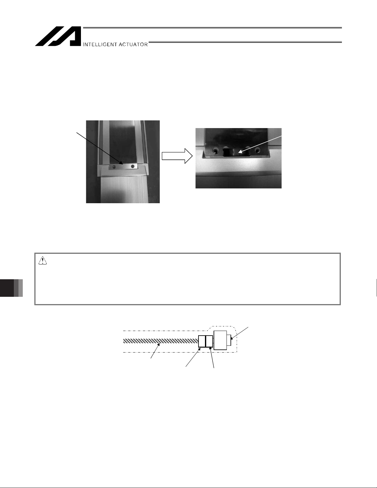
14.1 Removing the Motor Unit
(1) Removing the coupling cover
Turn off the power supply to the controller, and then disconnect the motor cable and encoder cable.
Remove the two screws used to secure the cover on the motor side using an Allen wrench of 2.5 mm across flats
for ISDB, ISPDB, ISDBCR and ISPDBCR-S, or 3 mm across flats for all other models.
The coupling will be visible.
Cover
Move the slider to a position where the coupling bolt can be loosened.
If the actuator is equipped with a brake, connect the encoder cable and apply power to the controller to release
the brake. Then move the slider so that the coupling bolts on the ball screw side can be removed.
After moving the slider, deactivate the brake release, turn off the power to the controller and disconnect the
encoder cable.
Caution: x When the actuator is vertically installed, exercise due caution so that the slider does not fall
when the brake is released. Be sure to support the slider externally to prevent it (work part)
from falling.
x If you attempt to move the slider with the motor cable connected, the slider movement will
become heavy due to regenerative braking. Disconnect the motor cable before moving the
slider.
Coupling
14. Motor Replacement Procedures
74
Ball screw
Coupling on the
ball screw side
Motor unit
Coupling on
the motor side
Page 83

(2) Removing the rear cover
[1] Remove the screws used to secure the cable mounting cover using an Allen wrench of 2 mm across flats.
Rear cover
Cable mounting
cover
[2] Remove the four bolts used to secure the rear cover using an Allen wrench of 2.5 mm across flats for ISDB,
ISPDB, ISDBCR and ISPDBCR-S, or 3 mm across flats for all other models.
Rear cover
[3] Slide the cable affixing cover to remove it from the rear cover.
Rear cover
Cable affixing cover
14. Motor Replacement Procedures
75
Page 84

(3) Removing the cable mounting cover
Remove the three bolts used to secure the cable mounting cover to the cable using an Allen wrench of 2.5
mm across flats.
(Note) After the motor is replaced, the motor cables must be installed on the cable affixing cover. Before
removing the affixing cover, mark the cables so that their installation positions can be checked later
on.
Cable mounting cover
(4) Removing the motor cover
Remove the two bolts used to secure the motor cover using an Allen wrench of 2.5 mm across flats for ISDB,
ISDBCR, ISPDB and ISPDBCR-S, or 3 mm across flats for all other models
The two bolts are found below the motor at positions at the back in the motor cover.
Motor
The unit will look like below after the motor cover is removed.
14. Motor Replacement Procedures
76
Motor cover
Bolts affixing the motor cover
Page 85

(5) Removing the motor unit
[1] Loosen the coupling tightening bolt.
Caution: If the actuator is installed
vertically, exercise due caution
not to let the slider drop.
Hold the slider (work part) from
the outside to prevent it from
dropping, and then loosen the
coupling bolt.
(2) Remove the bolts used to secure the motor using an Allen wrench of 4 mm across flats, and pull out the
motor unit and coupling from the motor housing.
Motor affixing bolt
Motor affixing bolt
Motor affixing bolt
Motor
Motor affixing bolt
14. Motor Replacement Procedures
Body Motor
77
Page 86
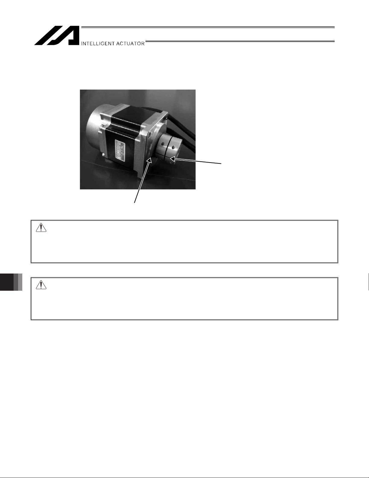
14.2 Installing a New Motor
(1) New motor unit
The new motor will be supplied together with the coupling installed as shown below.
Slit
Home mark
Caution: The motor actuator cable exit direction varies depending on the actuator cable exit direction.
The cable exit direction must be the same for the motor to be removed and new motor to be
installed.
If the cable exit direction is different on the installed motor, deviation of the home position will
occur.
Caution: Align the home mark on the motor with the slit position on the coupling, and then install the
motor/coupling into the actuator.
Never loosen the coupling on the motor side.
The slit in the coupling is provided to help correlate the actuator and encoder positions. If the
coupling is loosened, home return may not achieve a normal home position.
(2) Aligning the slider position
[1] Use extension cables (motor/encoder cables) to connect the motor cable and the encoder cable of the motor
unit to the controller.
14. Motor Replacement Procedures
78
Page 87

[2] Action to be taken upon error
x With XSEL or SSEL controller, if the 7-segment display on the front face of the controller does not show
“rdy” or “Ardy” but indicates an alarm after turning on the power, reset the alarm by checking the operation
manual. If the problem cannot be resolved, contact IAI.
The 7-segment display shows “Erg”: Cancel the emergency stop.
The 7-segment display shows “ECA1”: Perform absolute reset.
7-segment display
x With the SCON controller, if the PWR LED indicator on the front panel of the controller does not come on,
but the ALM indicator comes on instead, after turning on the power, connect the PC or teaching pendant
to check the nature of the alarm. Reset the alarm by checking the operation manual. If the problem cannot
be resolved, contact IAI.
Alarm code “0EE”: Perform absolute reset.
LED display
[3] Adjusting the Slider Position
If the actuator has a brake, turn on the controller power, release the brake, and move the slider to align the
slider position with respect to the mechanical end.
After moving the slider, deactivate the brake release, turn off the power to the controller and disconnect the
brake lead line connector.
14. Motor Replacement Procedures
79
Page 88

Standard home specification
[If a slider jig, etc. cannot be removed]
Reversed home specification
Set this part based on table 1 on next page.
The use of a block gauge is recommended also in this case.
14. Motor Replacement Procedures
80
Set this part based on table 1 on next page.
The use of a block gauge is recommended also in this case.
Page 89

(Table 1) Spacer Thickness by Model
Standard home specification
Adjust dimension to: (mm)
Type Lead
Standard Equipped with a limit switch =
Equipped with a home sensor
4 6 8 ISDB, ISPDB
ISDBCR, ISPDBCR-S
8 x 16 8 8
5 7 9 ISDB, ISPDB
ISDBCR, ISPDBCR-M
10 x 20 x 30 9 9
ISDB, ISPDB-MX 20 x 30 57 57
ISDBCR,
ISPDBCR-MX
ISDB, ISPDB
ISDBCR, ISPDBCR-L
20 x 30 58 58
10 x 20 x 40 9 9
ISDB, ISPDB-LX 20 x 40 55 55
ISDBCR, ISPDBCR-LX 20 x 40 57 57
SSPDACR-S 10 x 20 x 30 28.5 28.5
SSPDACR-M 10 x 20 x 40 32.5 32.5
SSPDACR-L 25 x 50 17 17
Reversed home specification
Adjust dimension to: (mm)
Type Lead
Standard Equipped with a limit switch =
Equipped with a home sensor
4 12 14 ISDB, ISPDB
ISDBCR, ISPDBCR-S
8 x 16 14 14
5 10 12 ISDB, ISPDB
ISDBCR, ISPDBCR-M
10 x 20 x 30 12 12
ISDB, ISPDB-MX 20 x 30 60 60
ISDBCR,
ISPDBCR-MX
ISDB, ISPDB
ISDBCR, ISPDBCR-L
10 x 20 x 30 61 61
10 x 20 x 40 23 23
ISDB, ISPDB-LX 20 x 40 69 69
ISDBCR, ISPDBCR-LX 20 x 40 71 71
SSPDACR-S 10 x 20 x 30 8.5 8.5
SSPDACR-M 10 x 20 x 40 5.5 5.5
SSPDACR-L 25 x 50 17 17
14. Motor Replacement Procedures
81
Page 90

(3) Aligning the motor position
Apply power to the controller, and then run the motor with the jog control using the PC software or teaching
pendant to align the home position marked on the motor and the slit in the coupling.
(Jog at 1 mm per second (minimum speed).)
* In certain situations such as when the controller is away from the motor, you can turn on the servo after
aligning the coupling and slit positions by hand.
Slit
Slit
position
Home marl
Home marl
Caution: Align the home mark on the motor with the slit position on the coupling, and then install the
motor/coupling into the actuator.
Never loosen the coupling on the motor side.
The slit in the coupling is provided to help correlate the actuator and encoder positions. If the
coupling is loosened, home return may not achieve a normal home position.
14. Motor Replacement Procedures
82
Page 91

(4) Installing the motor temporarily
[1] With the motor servo turned on, fit the motor unit’s coupling in the end of the ball screw shaft and fasten the
motor housing and motor unit temporarily. (Tighten manually for this temporary purpose.)
When fastening the motor and motor housing temporarily, be sure to place them next to each other with no
gaps or play.
If the cable exits from the right, install the motor as shown in the photograph below so that the motor cable is
positioned on the left side. If the cable exits from the left, install the motor in the position opposite of the
photograph.
Caution: The cable exit direction must be the same for the motor to be removed and new motor to be
installed.
If the cable exit direction is different on the installed motor, deviation of the home position will
occur.
14. Motor Replacement Procedures
83
Page 92

Type Bolt used
ISDB, ISDBCR,
ISPDB,
M4 x 12
ISPDBCR-S
ISDB, ISDBCR,
ISPDB, ISPDBCR,
M5 x 15
-M, MX, L, LX
SSPDACR-S M5 x 15
SSPDACR-M M5 x 15
SSPDACR-L M6 x 20
Four bolts used to secure the motor
[2] With the motor fastened temporarily, tighten the coupling bolts on the ball screw side.
[3] Turn off the power to the controller, disconnect all connectors (including the motor cable and encoder cable
connectors), but this time tighten the bolts in place to the specified torque.
<Tightening torques by coupling bolt type>
Type Tightening torque
ISDB, ISDBCR, ISPDB,
ISPDBCR-S
ISDB, ISDBCR,
ISPDB, ISPDBCR-M, MX
ISDB, ISDBCR,
ISPDB, ISPDBCR-L, LX
2.0 Nxm
2.0 Nxm
4.0 Nxm
SSPDACR-S 2.0 Nxm
SSPDACR-M 4.0 Nxm
SSPDACR-L 7.0 Nxm
14. Motor Replacement Procedures
84
Page 93

(5) Centering and securing the motor unit
Loosen the motor affixing screws you have tightened only loosely in an earlier step, move the slider back and
forth by hand for three to four cycles (over as long an operation stroke as possible) and eventually move the
slider to near the mechanical end on the motor side and find a position at which the motor vibration becomes
the smallest. Affix the motor unit in the motor housing at this position.
<Tightening torque of the bolt when motor is affixed>
Type Bolt used Tightening torque
ISDB, ISDBCR,
ISPDB, ISPDBCR-S
M4 x 12 176 Nxm
ISDB, ISDBCR,
ISPDB, ISPDBCR,
M5 x 15 342 Nxm
-M, MX, L, LX
SSPDACR-S M5 x 15 342 Nxm
SSPDACR-M M5 x 15 342 Nxm
SSPDACR-L M6 x 20 536 Nxm
(Note) If the actuator is equipped with a brake, connect the encoder cable of the motor unit to the controller using
the extension cables (motor and encoder cables), and apply power to the controller. Then release the
brake and move the slider.
For safety reasons, after securing the motor unit, deactivate the brake release, turn off the power to the
controller and disconnect the cable connectors from the motor unit.
14. Motor Replacement Procedures
85
Page 94

r
(6) Installing the motor cover
Tighten the two bolts to install the motor cover using an Allen wrench of 2.5 mm across flats for ISDB, ISPDB,
ISDBCR and ISPDBCR-S, or 3 mm across flats for all other models.
Two of these bolts are found below the motor at locations further back in the motor cover.
Motor
Motor cover
Bolts affixing the motor cover
(7) Installing the cable mounting cover
Tighten the three bolts using an Allen wrench of 2.5 mm across flats to install the cable mounting cover to the
cable. Install the cable mounting cover in roughly the same position as the area marked on the motor that
has been removed.
The cable mounting cover is imprinted with M and PG. Clamp the motor cable to the M side, and the encoder
cable to the PG side.
(Note) After the motor is replaced, install the cable mounting cover in roughly the same position as the
replaced motor. Mark the cable for the motor to be replaced so that the installation position can be
identified.
14. Motor Replacement Procedures
86
Cable mounting cove
Page 95

r
(8) Installing the rear cover
r
r
r
r
[1] Insert the cable affixing cover into the rear cover.
Cable mounting
cover
Rear cove
[2] Tighten the four bolts to install the rear cover using an Allen wrench of 2.5 mm across flats for ISDB, ISPDB,
ISDBCR and ISPDBCR-S, or 3 mm across flats for all other models.
Cable mounting cove
Rear cove
[3] Tighten the screws with an Allen wrench of 2 mm across flats to attach the screws for the cable mounting
cover.
Cable mounting cove
Rear cove
14. Motor Replacement Procedures
87
Page 96

(9) Installing the coupling cover
Tighten the two screws to install the cover on the motor side using an Allen wrench of 2.5 mm across flats for
ISDB, ISPDB, ISDBCR and ISPDBCR-S, or 3 mm across flats for all other models.
Coupling
Coupling
cover
14. Motor Replacement Procedures
88
Page 97

14.3 Correcting for Position Deviation
(1) Connect the motor cable and encoder cable and turn on the controller power.
(2) Use the PC software or teaching pendant to perform homing and check the home position. Repeat homing
several times to confirm that the actuator returns to the same position.
(If the actuator is of absolute specification, perform an absolute reset.)
(3) Check the amount of position deviation.
The position may have changed slightly from where it was before the motor was replaced.
Accordingly, select a desired position number that allows you to check the amount of deviation before and
after the replacement, and then perform positioning to that position and measure the amount of deviation.
(4) Reflect the deviation in the home preset parameter in the case of an X-SEL/SSEL controller, or in the home
return offset parameter in the case of an SCON controller. [For the setting method, refer to 9.5, “Fine-tuning
the Home Position.”]
* If the two positions differ significantly (one ball screw revolution or more = lead or more) or if the actuator does
not return to the same position when homing is repeated, install the motor unit again by following the
procedure described in this manual.
When the motor unit was installed, a wrong spacer size may have been used or the slider may have moved
instead of remaining stationary at the mechanical end.
14.4 Operation Check after Replacing the Motor
After replacing the motor, perform continuous operation to confirm absence of vibration or abnormal noise.
14. Motor Replacement Procedures
89
Page 98

15. Appendix
(
)
r
15.1 External Dimensions
15.1.1 ISDB, ISPDB-S
1.5 4.5
86
90
10
70
10
4545
5
2-6 H7, depth 10
4-M6, depth 19
Cable exit direction: Right
Cable exit direction: Rear
Cable exit direction: Left
Reference
5.47
Reference
surface
15. Appendix
3.7
surface
5.2
5.45
3.4
Detail View A
A
6
3
Machining jig holes are
provided across the bottom
surface of the base.
These holes are not used to
install the actuator.
Plug with rubber grommets.
Base installation surface fo
20.0±
06
06
90
70
51
1
38
84
90
guide specification
51
high-precision
077
Reference
surface
M.E. S.E.
Tapered tube screw (Rc 3/8)
(Plug with plug screw; same
on the opposite side)
11
8
57.5 50
25
+0.012
2-oblong, , depth 10
6H7
0
Hx200 pitch
B22
L
7 (from the reference surface)
154
B
Tapered tube screw (Rc 3/8)
(Plug with plug screw; same
on the opposite side)
20.0±
07
50
75.5
25.5100D×200F1007.5
4-6, H7 depth 10
5 4Stroke510
M.E.HOME
10
82.5 50W
117.5 (50W BK type)
86
Slider center position (home)
E-M6 depth 17
L Weight [kg]
Stroke
50 W motor 50 W motor
Without brake With brake
B D E F
Without brake With brake
100 382.5 417.5 278 0 8 45 4.1 4.3
150 432.5 467.5 328 0 8 95 4.4 4.6
200 482.5 517.5 378 0 8 145 4.8 5.0
250 532.5 567.5 428 0 8 195 5.1 5.3
300 582.5 617.5 478 1 10 45 5.5 5.7
350 632.5 667.5 528 1 10 95 5.9 6.1
400 682.5 717.5 578 1 10 145 6.2 6.4
450 732.5 787.5 628 1 10 195 6.6 6.8
500 782.5 817.5 678 2 12 45 7.0 7.2
550 832.5 867.5 728 2 12 95 7.3 7.5
600 882.5 917.5 778 2 12 145 7.7 7.9
650 932.5 967.5 828 2 12 195 8.1 8.3
700 982.5 1017.5 878 3 14 45 8.4 8.6
750 1032.5 1067.5 928 3 14 95 8.8 9.0
800 1082.5 1117.5 978 3 14 145 9.1 9.3
Cable length
Ø
Grease nipple for ball screw
Grease nipple for guide
(for supplying oil to the guide on
the installation surface side)
B (Same on the opposite side of grease nipples)
Screw for grounding wire
connection
M3 x 2 locations
6
06
90
Page 99

15.1.2 ISDB, ISPDB-M
(
)
r
1.5 4.5
3.4
3.7
Detail View A
Reference
surface
49
Reference
surface
5.96
116
94
69
5.2
1
A
6
54
110
5
120
22
M.E. S.E.
5.55
11
22
Tapered tube screw (Rc 3/8)
(Plug with plug screw; same on
the opposite side)
107
120
15
90
4-M6, depth 18
70
08
B
Tapered tube screw (Rc 3/8)
(Plug with plug screw; same on
B
L
the opposite side)
15
2525
6060
7
20.0±
08
2-8 H7, depth 10
4-M8, depth 18
5Stroke58 5194
M.E.HOME
10
100W
91
115 (100W BK type)
106 200W
141 (200W BK type)
Cable exit direction: Right
Cable exit direction: Rear
Cable exit direction: Left
300
Cable length
Screw for grounding wire
connection
Ø
6
Grease nipple for ball screw
Grease nipple for guide
(for supplying oil to the guide on
the installation surface side)
B (Same on the opposite side of grease nipples)
87
M3 x 2 locations
20.0±
09
60
120D×200F12012.5 42.5
102.572.5
4-8, H7 depth 10
107
Slider center position (home)
E-M8 depth 20
Machining jig holes are
provided across the bottom
surface of the base.
These holes are not used to
install the actuator.
Plug with rubber grommets.
Base installation surface fo
guide specification
09
01
Reference
surface
high-precision
12
30
60
+0.015
2-oblong , dep th 10
8 H7
0
10 (from the reference surface)
L Weight [kg]
Stroke
100 W motor 200 W motor 100 W motor 200 W motor
Without
brake
With
brake
Without
brake
With
brake
B D E F
Without
brake
With
brake
Without
brake
100 430 454 445 480 317 0 8 22 7.5 7.8 7.9 8.3
150 480 504 495 530 367 0 8 72 8.1 8.4 8.5 8.9
200 530 554 545 580 417 0 8 122 8.8 9.1 9.2 9.6
250 580 604 594 630 467 0 8 172 9.4 9.7 9.8 10.2
300 630 654 645 680 517 1 10 22 10.0 10.3 10.4 10.8
350 680 704 695 730 567 1 10 72 10.7 11.0 11.1 11.5
400 730 754 745 780 617 1 10 122 11.3 11.6 11.7 12.1
450 780 804 795 830 667 1 10 172 11.9 12.2 12.3 12.7
500 830 854 845 880 717 2 12 22 12.6 12.9 13.0 13.4
550 880 904 895 930 767 2 12 72 13.2 13.5 13.6 14.0
600 930 954 945 980 817 2 12 122 13.8 14.1 14.2 14.6
650 980 1004 995 1030 867 2 12 172 14.5 14.8 14.9 15.3
700 1030 1054 1045 1080 917 3 14 22 15.1 15.4 15.5 15.9
750 1080 1104 1095 1130 967 3 14 72 15.7 16.0 16.1 16.5
800 1130 1154 1145 1180 1017 3 14 122 16.4 16.7 16.8 17.2
850 1180 1204 1195 1230 1067 3 14 172 17.0 17.3 17.4 17.8
900 1230 1254 1245 1280 1117 4 16 22 17.6 17.9 18.0 18.4
950 1280 1304 1295 1330 1167 4 16 72 18.3 18.6 18.7 19.1
1000 1330 1354 1345 1380 1217 4 16 122 18.9 19.2 19.3 19.7
1050 1380 1404 1395 1430 1267 4 16 172 19.5 19.8 19.9 20.3
1100 1430 1454 1445 1480 1317 5 18 22 20.2 20.5 20.6 21.0
With
brake
15. Appendix
91
Page 100

5.1.3 ISDB, ISPDB-MX
)
r
1.5 4.5
3
3.4
.
7
Detail View A
Reference
surface
49
Reference
surface
116
94
69
5.2
A
5.9
6
6
22
54
1105
120
556 5 53Stroke
S.E.
M.E.
Tapered tube screw (Rc 3/8)
(Plug with plug screw; same
on the opposite side)
11
155
4-M6, depth 18
B22
L
90 1515
7025 25
6060
7
20.
0
±
08
08
194
B
Tapered tube screw (Rc 3/8)
(Plug with plug screw; same
on the opposite side)
M.E.HOME
106
2- 8 H7, depth 10
4-M8, depth 18
10
200W
141 (200W BK type)
Cable exit direction: Right
Cable exit direction: Rear
Cable exit direction: Left
Ø
6
300
Cable length
Grease nipple for ball screw
Grease nipple for guide
(for supplying oil to the guide on
the installation surface side)
B (Same on the opposite side of grease nipples)
Screw for grounding wire
connection (M3 x 2 locations
87
15. Appendix
Machining jig holes are
provided across the bottom
surface of the base.
These holes are not used to
install the actuator.
Plug with rubber grommets.
Base installation surface fo
guide specification
Reference
surface
high-precision
09
12
0
1
30
60
2-oblong , depth 10
8 H7
F
+0.015
0
10 (from the reference surface)
20.0±
09
60
120D×20012060.5 90.5
4-
150.5120.5
8, H7 depth 10
155
Slider center position (home)
E-M8 depth 20
L Weight [kg]
Stroke
200 W motor 200 W motor
Without
brake
With
brake
B D E F
Without
brake
With
brake
800 1241 1276 1113 3 14 122 18.3 18.8
900 1341 1376 1213 3 14 222 19.6 20.1
1000 1441 1476 1313 4 16 122 20.9 21.4
1100 1541 1576 1413 4 16 222 22.2 22.7
1200 1641 1676 1513 5 18 122 23.4 23.9
1300 1741 1776 1613 5 18 222 24.7 25.2
1400 1841 1876 1713 6 20 122 26.0 26.5
1500 1941 1976 1813 6 20 222 27.3 27.8
1600 2041 2076 1913 7 22 122 28.6 29.1
92
 Loading...