

Page 1

INTELLIGENT ACTUA TOR
Super SEL Controller
(Type E & G)
Operating Manual
Super SEL Type E
Intelligent Actuator Inc.
Page 2

This publication was written to assist you in better understanding this part of your IA system. If you require further assistance, please
contact IA Technical Support. For Central and East Coast Time Zones, please call our Itasca, IL office at 1-800-944-0333 or F AX 630467-9912. For Mountain and Pacific Time Zones, please call our Torrance, CA office at 1-800-736-1712 or FAX 310-891-0815; Monday
thru Friday from 8:00 AM to 5:00PM.
Intelligent Actuator, Inc.
U.S. Headquarters
2690 W. 237th Street
Torrance, CA 90501
310-891-6015 / 310-891-0815 fax
Intelligent Actuator, Inc.
Midwest Regional Office
1261 Hamilton Parkway
Itasca, IL 60143
630-467-9900 / 630-467-9912 fax
www .intelligentactuator.com
© December 1996 Intelligent Actuator, Inc. All rights reserved.
No portion of this publication may be reproduced, stored in a retrieval system, or transmitted, in any form or by any means, electronic,
mechnical, recording, or otherwise, without the prior written permission of Intelligent Actuator, Inc.
Disclaimer
The information and technical data contained herein are subject to change without notice. Intelligent Actuator, Inc. assumes no responsibility
for any errors or omissions regarding the accuracy of the information contained in this publication.
Page 3

Foreword
Thank you very much for purchasing the IA Super SEL Controller E·G Type. Without knowing beforehand how to correctly use
or operate the controller, not only will the user be unable to take full advantage of all the functions built into this product but he
might inadvertently cause damage to the controller or shorten its life. Please read this manual carefully to acquire an understanding of the proper method of handling and operating the controller. Keep the manual handy so that you can refer to the
appropriate sections as the need arises.
Your Super SEL Controller E·G Type has a built-in 32 bit RISC (Reduced Instruction Set Computer) CPU and uses SEL
language developed exclusively by IAI for programming. The Super SEL is a highly advanced, new generation of controller
that eliminates the need for a PLC, allows you to do multi-tasking (parallel processing), and allows you to network the controllers with the SEL NET option.
As with our other Super SEL controllers, the Super SEL E·G Type can be used with all IAI actuators. Type E is designed for
single axis control and Type G for multiple axes control. Please use the special cable provided to connect the actuator with the
controller.
*All precautions have been taken to ensure the accuracy of the contents of this manual. However, if you become aware of any
inaccuracies or discrepancies, please contact your IAI sales representative or technical service department.
Page 1
Page 4

Table of Contents
Foreword ................................................................................................................................................................. 1
Before You Begin...................................................................................................................................................... 4
Chapter 1 Setting Up ....................................................................................................................................... 5~63
Part 1 Safety Precautions ...............................................................................................................................................5
Part 2 Warranty Period and Scope.................................................................................................................................6
Part 3 Installation Environment and Noise Measures ..................................................................................................7
Part 4 Cabling Precautions ..........................................................................................................................................12
Part 5 Part Names and Functions ................................................................................................................................14
Part 6 Specifications ....................................................................................................................................................17
1 AC..................................................................................................................................................................17
2 DC..................................................................................................................................................................21
3 External I/O ................................................................................................................................................... 25
4 Servo ..............................................................................................................................................................26
5 Precautions When Using Emergency Stop ...................................................................................................27
6 Restarting the Controller After an Emergency Stop.....................................................................................27
Part 7 System Setup .....................................................................................................................................................28
1 Connecting the IA Controller and Actuator .................................................................................................28
2 Interface List..................................................................................................................................................29
3 I/O Wiring Diagram ......................................................................................................................................30
4 Teaching/RS232C Connector ........................................................................................................................ 33
5 Connector Pin Assignment ...........................................................................................................................34
6 Controller Dimensions ..................................................................................................................................49
7 Unit Configurations and Limitations ............................................................................................................52
8 Type G (AC) Unit Configurations.................................................................................................................56
9 12-slot Expansion Unit .................................................................................................................................. 61
10 Bleeder Resistor .............................................................................................................................................62
Part 8 Maintenance ......................................................................................................................................................63
Chapter 2 Operation ......................................................................................................................................64~93
Part 1 Basics in Operating Your Super SEL Controller .............................................................................................64
Part 2 Teaching Pendant Operation ............................................................................................................................66
Part 3 System Operation .............................................................................................................................................. 91
Chapter 3 Multi-tasking ............................................................................................................................. 94~105
Part 1 Real-time Multi-tasking ....................................................................................................................................94
1 Super SEL Programming Language .............................................................................................................94
2 Multi-Tasking ................................................................................................................................................ 95
3 Difference Between the Super SEL and a PLC.............................................................................................96
4 Emergency Stop Release ...............................................................................................................................97
5 Program Switching ........................................................................................................................................ 98
Part 2 Screwdriving Robot System .............................................................................................................................. 99
1 Components Used..........................................................................................................................................99
2 Operation .......................................................................................................................................................99
3 Screwdriving System Illustration ..................................................................................................................99
4 Hardware .....................................................................................................................................................100
5 Software .......................................................................................................................................................102
Page 2
Page 5

Table of Contents
Part 3 Multi-tasking Programming Tips ...................................................................................................................104
1 Inefficient Configuration.............................................................................................................................104
2 Most Efficient Configuration ......................................................................................................................105
Chapter 4 Programming .......................................................................................................................... 106~199
Part 1 Super SEL Language ......................................................................................................................................106
1 Numerals and Symbols................................................................................................................................106
2 I/O Ports....................................................................................................................................................... 107
3 Flags.............................................................................................................................................................108
4 Variable Register ......................................................................................................................................... 109
5 Tags.............................................................................................................................................................. 112
6 Subroutine.................................................................................................................................................... 113
7 Axis Designation .........................................................................................................................................114
Part 2 Super SEL Language Structure ......................................................................................................................116
1 Position Program .........................................................................................................................................116
2 Application Program ................................................................................................................................... 117
Part 3 Standard Commands .......................................................................................................................................119
1 Command Table ........................................................................................................................................... 119
2 Commands ...................................................................................................................................................121
Part 4 Expansion Commands ....................................................................................................................................162
1 Command Table ........................................................................................................................................... 162
2 Commands ...................................................................................................................................................163
Part 5 Parameter List .................................................................................................................................................185
Part 6 Application Program Examples......................................................................................................................188
1 Movement using Point Move Command .................................................................................................... 188
2 Palletizing Operation ..................................................................................................................................191
3 Circular Movement Command ....................................................................................................................194
4 Path Movement Command..........................................................................................................................195
5 BCD Code Signals Input and Output..........................................................................................................196
Chapter 5 Options ..................................................................................................................................... 200~236
1 Expansion I/O Card ...............................................................................................................................................200
2 High Speed Input Unit ...........................................................................................................................................201
3 SEL NET 2-Channel RS232C Unit .......................................................................................................................207
4 Flash Memory Card Unit .......................................................................................................................................230
5 PC Interface Software.............................................................................................................................................235
6 Optional I/O Expansion Module............................................................................................................................ 236
*Supplement ................................................................................................................................................ 237~254
1 Super SEL Controller 7 Segment Display .............................................................................................................237
2 Power Required by the Super SEL Controller .......................................................................................................238
3 Brake Specifications (Option)................................................................................................................................239
4 Heat Dissipation .....................................................................................................................................................243
5 I/O DC24V Power Supply......................................................................................................................................245
6 Emergency Stop......................................................................................................................................................247
7 Error Code List....................................................................................................................................................... 248
8 What to Do When an Error Code Occurs ..............................................................................................................249
Index ............................................................................................................................................................ 255~257
Page 3
Page 6

Before You Begin
Differences between the Super SEL Controller Type E/G and Type A/B
(Be sure to read this before you begin)
1. There is no built-in DC24V power supply for the I/O in the Super SEL Controller Type E/G. The DC24V power must be
supplied externally. Connect +24V to I/O connector Pin 1A, and 0V to Pin 25B. (Refer to "Supplement 5. I/O DC24V power
Supply" for more details.)
2. For the Super SEL Controller Type E·G, the Emergency Stop is normally closed. To release the Emergency Stop, Pin 2B and
0V must be short-circuited. To release the Emer gency Stop for testing, short-circuit the jumper post (ST1) placed at the bottom
of the controller CPU UNIT or CPU SERVO UNIT with a jumper pin. Even in this case, the Emergency Stop function from
the teaching pendant is still effective. (Refer to Supplement 6. Emergency Stop)
Note: After testing, please make sure to take the jumper pin out so that the Emergency Stop operates externally.
3. The Super SEL Type E·G Controllers are designed to be mounted inside of a control panel. For cooling, the heat sink method
or forced air current method is recommended. (Refer to Supplement 4. Heat Dissipation)
! A Word of Caution
Please read this manual carefully to operate the controller properly.
You are not allowed to use or reproduce this manual or any portion thereof without permission.
We cannot accept any responsibility for possible damage resulting from the use of this manual.
We reserve the right to change the information contained in this manual without prior notice.
! Emergency Procedures
If hazardous conditions arise while using the controller, immediately turn OFF all power switches for the controller and any
devices connected to it, or pull all the power plugs from the electric outlet. ("Hazardous condition" refers to excessive heat,
smoke or flames coming from the controller or any conditions which might lead to fire or cause damage to the controller.)
Page 4
Page 7

Chapter 1. Setting Up
Part 1 Safety Precautions
The IA Super SEL Controller Type E was designed to control any type single axis IAI actuator and Type G was designed to
control any type actuator in assembly configurations using a maximum of 8 axes or integrated with other peripheral devices. It
is capable of controlling everything from a simple single axis system to large scale FA (factory automation) system. As systems
become more complicated, the possibility of incorrect operation or accidents arising from carelessness also increases. Please
take sufficient care when operating your system.
Please follow the following safety precautions when operating your IA system:
(1) Any operation not specifically addressed in this manual should not be attempted. If you have any questions, please
contact your IA sales representative or contact IA technical support at: 1-800-736-1712.
(2) Use only IA cables when connecting IA actuators and controllers. IA cables are matched for use with IA actuators and
are specially designed to withstand repeated bending.
(3) Stand clear of your IA system when operating or preparing to operate. Surround your IA system with safety partitions
if there is any possibility that someone may become injured by an operating IA system.
(4) Before assembling, adjusting, or performing maintenance on your IA system, please make sure that people around you
are aware that the system is not to be powered up or turned on. You may want to disconnect the power cable completely, keep the power cable close to the operator, or use a safety plug to ensure that the power cable will not be
plugged in inadvertently.
(5) When more than one person is working on your IA system, use signs to inform everyone of the operating status of the
equipment. Make sure that everyone stands clear prior to operation. Operate your system only after you are sure that
everyone knows that you are initiating system start-up and that everyone is clear of the system.
(6) In situations where the cables must be lengthened, be sure to double check all connections before powering up your IA
system.
Page 5
Page 8

Chapter 1. Setting Up
Part 2 Warranty Period and Scope
The Super SEL controller undergoes stringent testing before it is shipped from our factory. IAI provides the following warranty.
1. Warranty Period
The warranty period is 12 months from the date the unit is shipped to the customer.
2. Scope of Warranty
If within the period specified above, a breakdown occurs while operating the controller under normal conditions and is
clearly the responsibility of the manufacturer, IAI will repair the unit at no cost. However, the following items are not
covered by this warranty.
•Faded paint or other changes that occur naturally over time.
•Consumable components that wear out with use (battery, etc.).
•Unit seems to be noisy or similar impressions that do not affect machinery performance.
•Damage resulting from improper handling or use.
•Damage resulting from user error or failure to perform proper maintenance.
•Any alterations not authorized by IAI or its representatives.
•Damage caused by fire and other natural disasters or accidents.
The warranty pertains to the purchased product itself and does not cover any loss that might arise from a breakdown of the
product. Any repairs will be done at our factory.
3. Service
The purchase price of the product does not include programming or expenses for sending technicians to the customer's site.
Even if the product is still under the warranty period, separate charges will be assessed for the following services.
•Assistance with unit installation or trial operation.
•Inspection and maintenance.
•Technical instruction and training for controller operation and wiring.
•Writing programs or technical instruction and training for programming.
•Any other services or work for which IAI normally assesses separate charges.
Page 6
Page 9

Chapter 1. Setting Up
Part 3 Installation Environment and Noise Measures
1. Installation Environment
(1) Do NOT block the air vents of your controller when installing your IA system.
(2) Your Super SEL Controller is NOT dust, water, or oil proof. Take steps to prevent foreign matter from getting into the
controller air vents. A void using your IA system in environments subject to contamination by dust, oil mist, or cutting oil.
(3) Do not expose your IA system to direct sunlight or place it near a heat source.
(4) Avoid placing your IA system under conditions of extreme tempreratures above 50
o
C (120oF) or below 0oC (32oF). The
area level of humidity should not be above 85%. Do NOT expose to corrosive or inflammable gas.
(5) Avoid external vibration, unnecessary impact, or excessive shocks to your IA system.
(6) Take steps to shield all cables and wires from electromagnetic noise.
2. Power Source
Make certain that an AC line voltage of 90 ~ 127V (Rated 100 ~ 120V) is maintained. If the power supply tends to fluctuate
substantially, use a constant-voltage transformer.
3. Electromagnetic Noise Supression
(1) Wiring and Power Supply
For grounding, please use a dedicated ground of Class 3 or better. The thickness of the cable should be
2.0~5.5mm
2
or larger.
IA Controller
Other
Devices
IA Controller
Other
Devices
Class 3 ground Correct
Avoid this method
Page 7
Page 10
Chapter 1. Setting Up
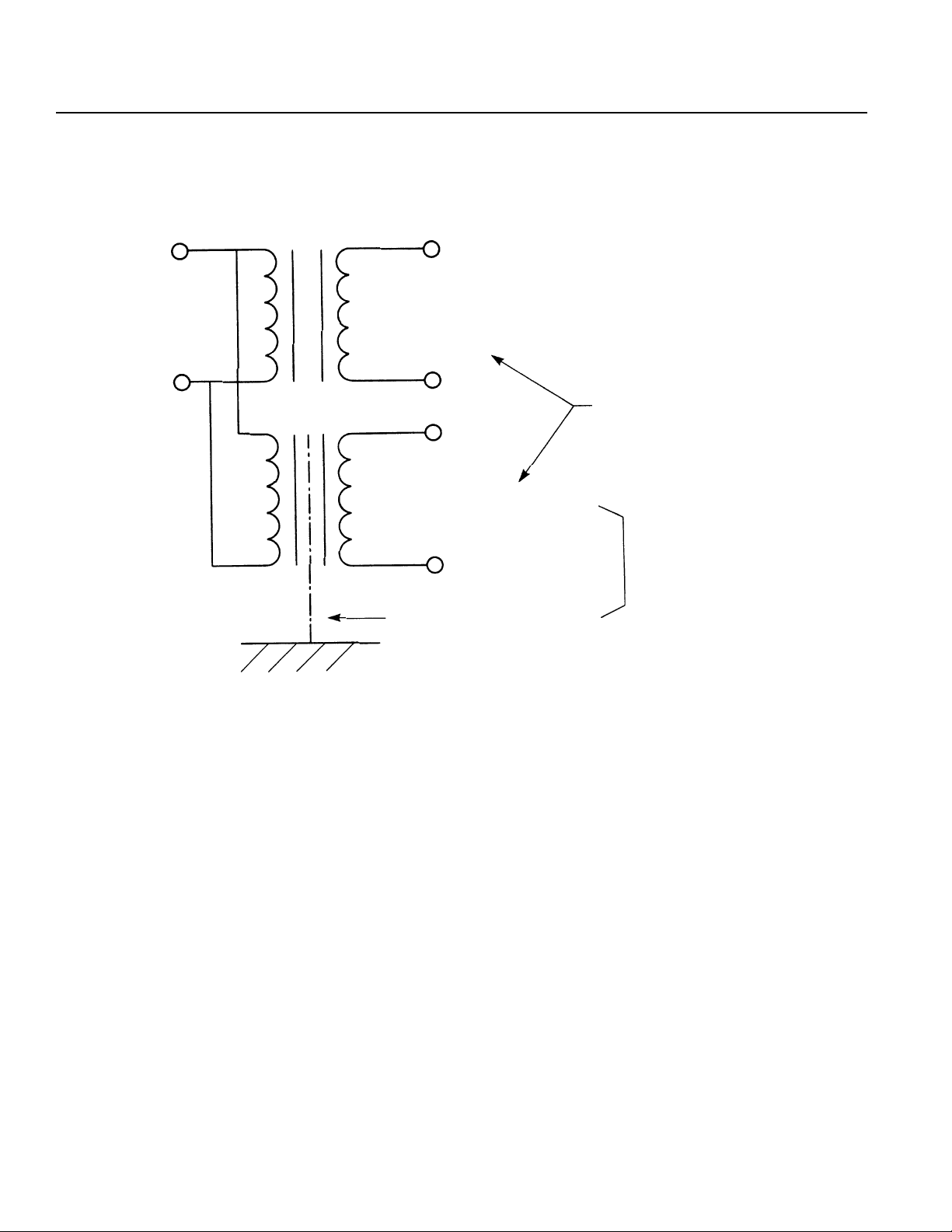
If you need to use a stepdown transformer to lower the power voltage from 240V to 117V, use a dedicated, insulated
transformer for the IA controller. (For further details, please contact your IA sales representative or technical support).
240V
117V
1 17V
Insulated transformer
with static shield
Other devices
IA Controller
Separate
Dedicated
transformer
Page 8
Page 11

Chapter 1. Setting Up
Please use a dedicated and insulated power transformer when the system has a 240V power source.
AC 117V
Main power
source
IA
power
Other
devices
Other
power
AC 240V
Main power
source
IA
power
240V 240V
117V
devices
Other
power
1 17V
1 17V
Main
circuit
240V
devices
IA Controller
Wiring Notes
1. To reduce noise problems, the AC117V and the DC24V external power cable should be a twisted pair.
2. Isolate the SEL cables from the power line.
3. For DC motors, isolate the encoder cable from the motor cable.
4. For AC motors, the motor and encoder cables are partially wired together but when the length of the cable
extends more than 5m, please wire them separately.
5. Consult with IAI if you need to extend the motor and encoder cables beyond the length that comes with the
controller.
IA Controller
Page 9
Page 12
Chapter 1. Setting Up
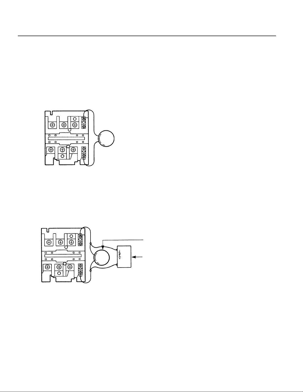
(2) Noise Source and Noise Suppression
When using electrical components such as electromagnets, solenoids, or relays which create electromagnetic noise,
some type of noise supression device should be used.
AC solenoid valve · magnetic switch · relay
• Install a surge absorber parallel to the reactance load (solenoid and relay coils).
*Note* Use the shortest possible wiring between the surge absorber
and the noise-creating device. Use of excessively long wiring will decrease the performance of the surge absorber.
• The most effective method is to install a surge absorber and surge killer in parallel to the reactance load (solenoid
and relay coils). This will reduce noise in a wide band of frequencies.
Surge Absorber (Metal Oxide Varistor or Transzorb).
Surge Killer (Resistor Capacitor Snubber)
Page 10
Page 13
Chapter 1. Setting Up
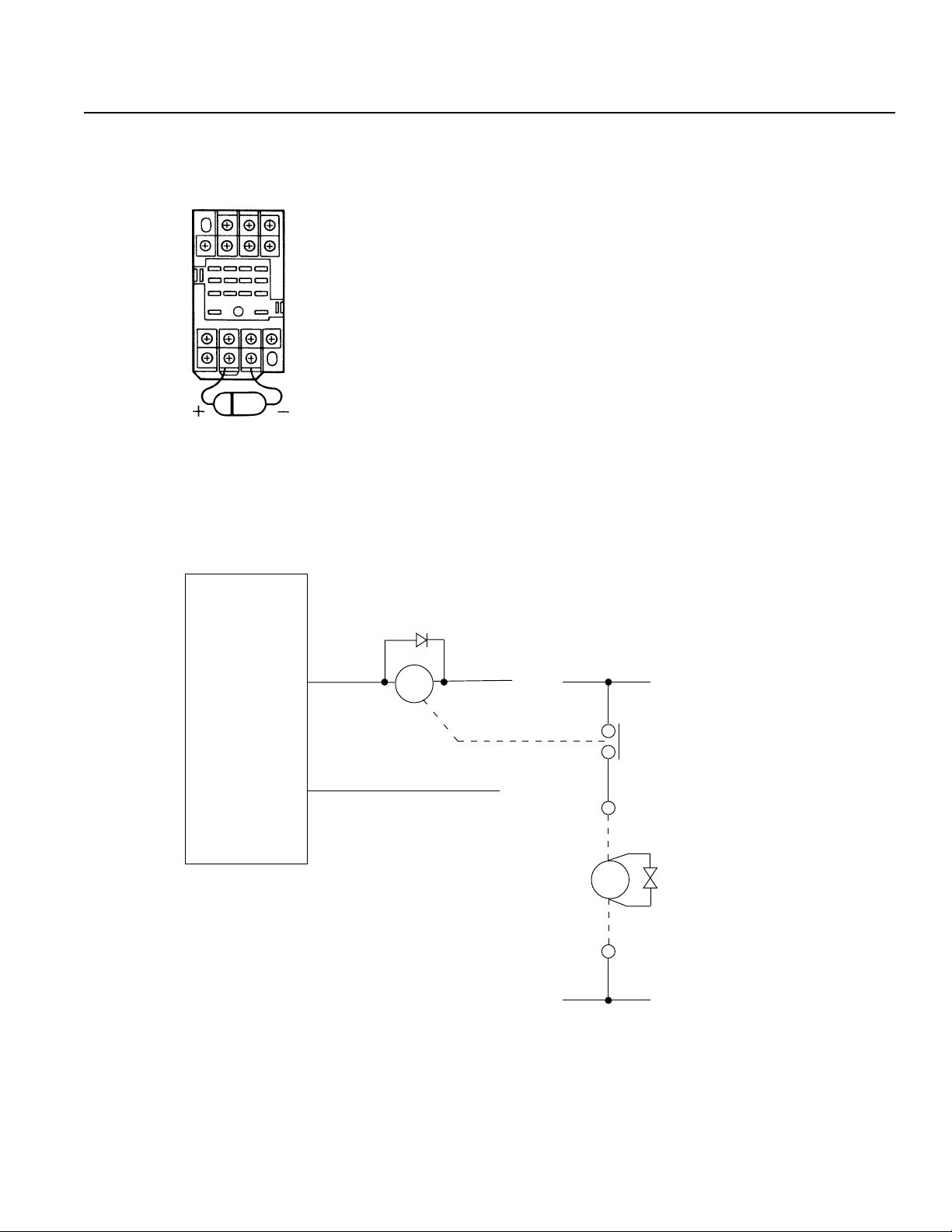
DC solenoid valve · magnetic switch · relay
• Install a diode parallel with a reactive/inductive load.
Circuit Example
• Select a diode with the proper voltage rating. The voltage rating is
determined by the loading capacity of the system.
• When installing the diode, pay careful attention to the polarity of the
diode. A diode installed in reverse polarity could damage your IA
System's internal circuitry.
• If the Controller output will be driving a 24V relay or a 120V solenoid valve, the diode must be installed to reduce any noise made by
these devices.
IA Super SEL
Controller
OUT
COM
MY2
DC24V
CR
24V
0V
AC 117V
CR
SOL
0V
Solenoid Valve
ENB221D-14A
Page 11
Page 14

Chapter 1. Setting Up
Part 4 Cabling Precautions
When using the IA actuator and controller to build an application system, it is important to position and lay out the cable correctly.
If this is not done, the cable may snap or have a faulty connection that could lead to a variety of problems which in turn could cause
the actuator to run out of control. Below, we explain the things not to do to ensure that the cables are connected in the correct
fashion.
Ten “Do’s and Don’ts” When Laying Out Cable (Please make sure to observe these rules!)
1 Make sure there is no excessive bending at one spot.
Steel band
(piano wire)
Bundle loosely
2 Do not twist or crease the cable. 3 Do not stretch the cable too tautly.
4 Do not exert rotational force at a single spot on the cable.
Use a
spiral cord
6 Do not cut, dent or let the cable get caught in something.
5 When affixing the cable, do not clamp it too tightly.
Do not use spiral tubing on a section
of the cable that bends frequently.
Page 12
Page 15

Chapter 1. Setting Up
7 If placing cable in a cableveyor or flexible tube, make sure it does not twist around. Also, make sure the cables have some
freedom of movement and are not bunched up (cable should not project out at bending points).
8 The amount of cable placed inside a cableveyor should
9
Do not mix the signal line with a high voltage circuit.
be about 60% of the space capacity of the cableveyor.
Cableveyor
Power supply circuit
Cable
Signal line
(flat cable, etc.)
Duct
10 In a case where the cable will be subject to forced bending, always use robot cable.
[Standard structure]
Outer covering
Varies according to
manufacturer and type
Protective layer
Shield
* When to use Robot Cable
When assembling two or three axes and connecting cable to the moving parts, bending weight will be repeatedly applied to the
base of the cable. In this case, the cable core is very likely to snap. T o prevent this from happening, we strongly recommend the
use of robot cable which has greatly improved capacity to withstand bending.
Signal line (copper + tin)
Absorption material
(when the cable bends
and there is pressure
from the outside signal
line, this absorbs the inner and outer difference)
Page 13
Page 16

Chapter 1. Setting Up
Part 5 Part Names and Functions
1. IA Controller Front View
Code (Code Display)
Controller operating status display (2 digit, 7 segment)
Ready (Ready Display LED)
Indicates if the controller is operable.
Alarm (Alarm Display LED)
Alerts the operator of any abnormality in the system.
Teaching/RS232C Connector
Connector for Teaching Pendant or PC.
Page 14
Page 17

Chapter 1. Setting Up
2. Controller Bottom View
LS (Limit Switch Connector) (Option)
5 pins, limit switch connector (Model: Nippon Molex 53258-0520)
BK (Brake Connector) (Option)
4 pins, brake output connector to a brake unit (option) (Model: Nippon Molex
53258-0420)
M·PG (Servo Motor Output/Encoder Input Connector)
14 pins, servo motor output/encoder input combined type connector (Axis 1 is
on the left and Axis 2 is on the right) (Model: Nippon Molex 53258-1420)
Power (Power Cable Connector)
3 pins, AC power supply cable connector
Since Type E and Type G are designed to be mounted inside of a controller
panel, no plug is provided for the power cable on the other end of the controller.
(Terminal Type) (Model: Nippon Molex 53265-0320)
I/O (I/O Connector)
50 pins, external I/O connector. This is used for Type E and Type G (2 axis)
up to 100W only. For other models, it is attached to the I/O Unit Box.
(Model: Sumitomo 3M 7950-6500FL)
SEL NET (Optional SEL Network Connector)
SEL. Network transmission connector. (Model: Nippon Molex 53259-0620)
*Power Cable, Terminal
No. Color Signal
1BlackAC117V
2--- --3 White AC117V
4--- --5Green FG
ST1
Emergency Stop release jumper post. Refer to "Supplement 6. Emergency Stop".
Page 15
Page 18

Chapter 1. Setting Up
3. Teaching Pendant (Option)
LCD Display
4 lines with a 20 character per line capacity display. Shows program and Motion status.
Emergency Stop
When the emergency stop button is pressed, servos will disengage and all programmable outputs will be turned OFF.
To release the emergency stop, press Restart (F1) on the LCD Display.
F1, F2, F3, F4 (Function Key)
Multi-function keys which correspond with the LCD Display.
ESC (Escape)
The escape key allows the operator to go backwards in one-step increments to previous displays to make corrections or
to switch to different modes.
= <
Dual function keys for use in data input and axis Jog functions.
↵ ↵
↵ (Return Key)
↵ ↵
Return key is used to change operations and to move the cursor position.
Page 16
Page 19

Chapter 1. Setting Up
Part 6 Specifications
1. AC Specifications
(1) Type E (1 Axis)
Number of Axes AC60W ·100W x1 AC200W x1 AC400Wx1
Power Voltage AC 117V±10%
Power Frequency 50/60Hz
Power Consumption
Ambient Temperature and Humidity Temperature 0~40°C, Humidity less than 85%RH
Am bient Environment No corrosive gas, minimal dust
Isolation Resistance 500V 10MΩ or more
Noise Im munity*1 1500V 1µsec pulse by no ise simulator
Unit Weight (kg) 1.2 2.5 3.0
Protective Functions
Motor Capacity
Mem ory Capacity Total 3,000 steps 2,000 positions *2
Number of Programs 64 programs, 16 multi-tasking programs
Memory Device CMOS RAM battery backup
Dedicated Input External start · Emergency stop · Limit switch
Standard I/O
I/O
(DC24V)
Data Input M ethod Teaching pendant or RS232C communications
Expansion I/O
Maximum I/O
(including dedicated I/O)
Comm unications EIA RS232C Asynchronous, Full duplex
Network SEL NET RS232C network
175W (100Wx1)
≈
AC servo motor
60W · 100W
Extended I/O: 1 module 24 inputs, 24 outputs
--- 3 3
24 inputs *3
24 outputs
Output maximum load current 100mA/1 point
345W
≈
Driver temperature check
Overload check
S oftw a re lim it c he ck
AC servo motor
200W
24 inputs (including dedicated inputs)
24 outputs (including dedicated outputs)
96 inputs
96 outputs
(Recommended 20mA/1 point)
Transistor array: TD62083AF compatible
600W
≈
AC servo motor
400W
96 inputs
96 outputs
*1 Controller unit test
*2 The maximum number of steps that can be compiled per unit is 1999.
*3 96 inputs and 96 outputs are available by connecting an optional expansion unit box.
60W·100W
200W
400W
Page 17
Page 20

Chapter 1. Setting Up
(2) Type G (2-Axis)
Number of Axes AC60W ·100W x2 AC200W x2 AC400Wx2
Power Voltage AC 117V±10%
Power Frequency 50/60Hz
Power Consumption
Am bient Temperature and Humidity Tem perature 0~40°C, Humidity less than 85% RH
Am bient Environment No corrosive gas, minim al dust
Isolation Resistance 500V 10M
Noise Im munity*1 1500V 1µsec pulse by noise simulator
Unit W eight (kg) 1.2 2.7 3.5
Protective Functions
Motor Capacity
Mem ory Capacity Total 3,000 steps 2,000 positions *2
Number of Programs 64 programs, 16 multi-tasking programs
Memory Device CMOS RAM battery backup
Dedicated Input E xternal start · Emergency stop · Limit switch
Standard I/O
I/O
(DC24V)
Data Input Method Teaching pendant or RS232C comm unications
Expansion I/O
Maximum I/O
(including dedicated I/O)
Comm unications E IA RS 232C Asynchronous, Full duplex
Network SEL NET RS232C network
300W (100W x2)
≈
AC servo motor
60W · 100W x2
Extended I/O : 1 module 24 inputs, 24 outputs
--- 3 3
24 inputs *3
24 outputs
Output maximum load current 100m A/1 point
590W
≈
or more
Ω
Driver temperature check
Overload check
S oftw a re lim it ch e ck
AC servo motor
200Wx2
24 inputs (including dedicated inputs)
24 outputs (including dedicated outputs)
96 inputs
96 outputs
(Recommended 20mA /1 point)
Transistor array: TD62083AF compatible
11 0 0W
≈
AC servo motor
400Wx2
96 inputs
96 outputs
*1 Controller unit test
*2 The maximum number of steps that can be compiled per unit is 1999.
*3 96 inputs and 96 outputs are available by connecting an expansion unit box (option).
60W·100Wx2
200Wx2
Page 18
400Wx2
Page 21

Chapter 1. Setting Up
(3) Type G (4-Axis)
Number of Axes AC60W ·100W x4 AC200W x4 AC400Wx4
Power Voltage AC 117V±10%
Power Frequency 50/60Hz
Power Consumption
Am bient Temperature and Humidity Tem perature 0~40°C, Humidity less than 85% RH
Am bient Environment No corrosive gas, minim al dust
Isolation Resistance 500V 10M
Noise Im munity*1 1500V 1µsec pulse by noise simulator
Unit W eight (kg) 2.7 3.5 4.7
Protective Functions
Motor Capacity
Mem ory Capacity Total 3,000 steps 2,000 positions *2
Number of Programs 64 programs, 16 multi-tasking programs
Memory Device CMOS RAM battery backup
Dedicated Input E xternal start · Emergency stop · Limit switch
Standard I/O
I/O
(DC24V)
Data Input Method Teaching pendant or RS232C comm unications
Expansion I/O
Maximum I/O
(including dedicated I/O)
Comm unications E IA RS 232C Asynchronous, Full duplex
Network SEL NET RS232C network
600W (100W x4)
≈
AC servo motor
60W · 100W x4
Extended I/O : 1 module 24 inputs, 24 outputs
333
96 inputs
96 outputs
Output maximum load current 100m A/1 point
1080W
≈
or more
Ω
Driver temperature check
Overload check
S oftw a re lim it ch e ck
AC servo motor
200Wx4
24 inputs (including dedicated inputs)
24 outputs (including dedicated outputs)
96 inputs
96 outputs
(Recommended 20mA /1 point)
Transistor array: TD62083AF compatible
2100W
≈
AC servo motor
400Wx4
96 inputs
96 outputs
*1 Controller unit test
*2 The maximum number of steps that can be compiled per unit is 1999.
60W·100Wx4 200Wx4
400Wx4
Page 19
Page 22

Chapter 1. Setting Up
(4) Type G (8-Axis)
Num ber of Axes A C60W ·100W x8 A C200Wx8
Power Voltage AC 117V±10%
Power Frequency 50/60Hz
Power Consum ption
Am bient Tem perature and Hum idity Temperature 0~40°C, Humidity less than 85%RH
Am bient Environment No corrosive gas, m inimal dust
Isolation Resistance 500V 10M
Noise Imm unity*1 1500V 1µ sec pulse by noise sim ulator
Unit W eight (kg) 4.5 5.7
Protective Functions
Motor Capacity
Mem ory Capacity Total 3,000 steps 2,000 positions *2
Num ber of Programs 64 programs, 16 multi-tasking programs
Memory Device CMOS RAM battery backup
Dedicated Input External start · Em ergency stop · Limit switch
Standard I/O
I/O
(DC24V)
Data Input Method Teaching pendant or RS 232C comm unications
Expansion I/O
Maximum I/O
(including dedicated I/O )
Com munications EIA R S232C Asynchronous, Full duplex
Network SEL N ET RS232C netw ork
1100W (100W x8)
≈
or more
Ω
Driver temperature check
Overload check
S o ftw a re lim it c he c k
AC servo motor
60W · 100W x8
48 inputs (including dedicated inputs)
48 outputs (including dedicated outputs)
Extended I/O : 1 m odule 24 inputs, 24 outputs
10 10
288 inputs
288 outputs
Output m axim um load current 100mA/1 point
(Recomm ended 20mA/1 point)
Transistor array: TD62083AF com patible
AC servo motor
2000W
≈
200W x8
288 inputs
288 outputs
*1 Controller unit test
*2 The maximum number of steps that can be compiled per unit is 1999.
± A 12-slot expansion unit is available as an option (please see P. 61).
60W·100Wx8
200Wx8
Page 20
Page 23

Chapter 1. Setting Up
2. DC Specifications
(1) Type E (1 Axis)
Num ber of Axes DC 20W~100W x1 DC 200Wx1
Power Voltage AC 117V±10%
Power Frequency 50/60Hz
Power Consum ption
Am bient Tem perature and Hum idity Temperature 0~40°C, Humidity less than 85%RH
Am bient Environment No corrosive gas, m inimal dust
Isolation Resistance 500V 10M
Noise Imm unity*1 1500V 1µ sec pulse by noise sim ulator
Unit W eight (kg) 1.2 2.5
Protective Functions
Motor Capacity
Mem ory Capacity Total 3,000 steps 2,000 positions *2
Num ber of Programs 64 programs, 16 multi-tasking programs
Memory Device CMOS RAM battery backup
Dedicated Input External start · Em ergency stop · Limit switch
Standard I/O
I/O
(DC24V)
Data Input Method Teaching pendant or RS 232C comm unications
Expansion I/O
Maximum I/O
(including dedicated I/O )
Com munications EIA R S232C Asynchronous, Full duplex
Network SEL N ET RS232C netw ork
*1 Controller unit test
*2 The maximum number of steps that can be compiled per unit is 1999.
*3 96 inputs and 96 outputs are available by connecting an expansion unit box (option).
210W (100W x1)
≈
or more
Ω
Driver temperature check
Overload check
S o ftw a re lim it c he c k
DC servo motor
20~100W
24 inputs (including dedicated inputs)
24 outputs (including dedicated outputs)
Extended I/O : 1 m odule 24 inputs, 24 outputs
--- 3
24 inputs *3
24 outputs
Output m axim um load current 100mA/1 point
(Recomm ended 20mA/1 point)
Transistor array: TD62083AF com patible
DC servo motor
370W
≈
200W
96 inputs
96 outputs
20W~100W
200W
Page 21
Page 24

Chapter 1. Setting Up
(2) Type G (2-Axis)
Num ber of Axes DC 20W~100W x2 DC 200Wx2
Power Voltage AC 117V±10%
Power Frequency 50/60Hz
Power Consum ption
Am bient Tem perature and Hum idity Temperature 0~40°C, Humidity less than 85%RH
Am bient Environment No corrosive gas, m inimal dust
Isolation Resistance 500V 10M
Noise Imm unity*1 1500V 1µ sec pulse by noise sim ulator
Unit W eight (kg) 1.2 2.7
Protective Functions
Motor Capacity
Mem ory Capacity Total 3,000 steps 2,000 positions *2
Num ber of Programs 64 programs, 16 multi-tasking programs
Memory Device CMOS RAM battery backup
Dedicated Input External start · Em ergency stop · Limit switch
Standard I/O
I/O
(DC24V)
Data Input Method Teaching pendant or RS 232C comm unications
Expansion I/O
Maximum I/O
(including dedicated I/O )
Com munications EIA R S232C Asynchronous, Full duplex
Network SEL N ET RS232C netw ork
370W (100W x2)
≈
or more
Ω
Driver temperature check
Overload check
S o ftw a re lim it c he c k
DC servo motor
20~100W x2
24 inputs (including dedicated inputs)
24 outputs (including dedicated outputs)
Extended I/O : 1 m odule 24 inputs, 24 outputs
--- 3
24 inputs *3
24 outputs
Output m axim um load current 100mA/1 point
(Recomm ended 20mA/1 point)
Transistor array: TD62083AF com patible
DC servo motor
640W
≈
200W x2
96 inputs
96 outputs
*1 Controller unit test
*2 The maximum number of steps that can be compiled per unit is 1999.
*3 96 inputs and 96 outputs are available by connecting an expansion unit box (option).
20W~100W
200W
Page 22
Page 25

Chapter 1. Setting Up
(3) Type G (4-Axis)
Num ber of Axes DC 20W~100W x4 DC 200Wx4
Power Voltage AC 117V±10%
Power Frequency 50/60Hz
Power Consum ption
Am bient Tem perature and Hum idity Temperature 0~40°C, Humidity less than 85%RH
Am bient Environment No corrosive gas, m inimal dust
Isolation Resistance 500V 10M
Noise Imm unity*1 1500V 1µ sec pulse by noise sim ulator
Unit W eight (kg) 2.7 3.5
Protective Functions
Motor Capacity
Mem ory Capacity Total 3,000 steps 2,000 positions *2
Num ber of Programs 64 programs, 16 multi-tasking programs
Memory Device CMOS RAM battery backup
Dedicated Input External start · Em ergency stop · Limit switch
Standard I/O
I/O
(DC24V)
Data Input Method Teaching pendant or RS 232C comm unications
Expansion I/O
Maximum I/O
(including dedicated I/O )
Com munications EIA R S232C Asynchronous, Full duplex
Network SEL N ET RS232C netw ork
740W (100W x4)
≈
or more
Ω
Driver temperature check
Overload check
S o ftw a re lim it c he c k
DC servo motor
20~100W x4
24 inputs (including dedicated inputs)
24 outputs (including dedicated outputs)
Extended I/O : 1 m odule 24 inputs, 24 outputs
33
96 inputs
96 outputs
Output m axim um load current 100mA/1 point
(Recomm ended 20mA/1 point)
Transistor array: TD62083AF com patible
DC servo motor
11 80 W
≈
200W x4
96 inputs
96 outputs
*1 Controller unit test
*2 The maximum number of steps that can be compiled per unit is 1999.
20W~100Wx4 200Wx4
Page 23
Page 26
Chapter 1. Setting Up
(4) Type G (8-Axis)
Num ber of Axes DC 20W~100W x8 DC 200Wx8
Power Voltage AC 117V±10%
Power Frequency 50/60Hz
Power Consum ption
Am bient Tem perature and Hum idity Temperature 0~40°C, Humidity less than 85%RH
Am bient Environment No corrosive gas, m inimal dust
Isolation Resistance 500V 10M
Noise Imm unity*1 1500V 1µ sec pulse by noise sim ulator
Unit W eight (kg) 4.5 5.7
Protective Functions
Motor Capacity
Mem ory Capacity Total 3,000 steps 2,000 positions *2
Num ber of Programs 64 programs, 16 multi-tasking programs
Memory Device CMOS RAM battery backup
Dedicated Input External start · Em ergency stop · Limit switch
Standard I/O
I/O
(DC24V)
Data Input Method Teaching pendant or RS 232C comm unications
Expansion I/O
Maximum I/O
(including dedicated I/O )
Com munications EIA R S232C Asynchronous, Full duplex
Network SEL N ET RS232C netw ork
1380W (100W x8)
≈
or more
Ω
Driver temperature check
Overload check
S o ftw a re lim it c he c k
DC servo motor
20~100W x8
48 inputs (including dedicated inputs)
48 outputs (including dedicated outputs)
Extended I/O : 1 m odule 24 inputs, 24 outputs
10 10
288 inputs
288 outputs
Output m axim um load current 100mA/1 point
(Recomm ended 20mA/1 point)
Transistor array: TD62083AF com patible
DC servo motor
2260W
≈
200W x8
288 inputs
288 outputs
*1 Controller unit test
*2 The maximum number of steps that can be compiled per unit is 1999.
± A 12-slot expansion unit is available as an option (please see P. 61).
20W~100Wx8
200Wx8
Page 24
Page 27

Chapter 1. Setting Up
3. External I/O Specifications
(1) Input
Input Specifications
Dedicated Input...4 Points
Point
Power Voltage DC24V +/-20%
Current 7mA/DC24V
ON/OFF Power Voltage ON....Min DC16.0V OFF....Max DC5.0V
ON/OFF Response Time ON....Max 20m sec OFF....Max 20m sec
Isolation Method Photocoupler
Internal Circuit
User Input....20 Points
Expansion Input (Option)....Max 72 Points
External power
Internal
Circuit
Each input
1) The power must be supplied externally for the standard I/O board and the expansion I/O board.
2) For the external circuit connection (no contact point), the leakage per 1point must be kept lower than 1mA when the
switch is OFF.
Guaranteed operation width of the Super SEL Controller input signal
Time Width while ON
30msec
Time Width while OFF
30msec
Generally, the input signal operates within 25msec but the guaranteed operation width is 30msec.
Page 25
Page 28

Chapter 1. Setting Up
(2) Output
Output Point
Rated Power DC24V
Maximum Load Current 100m A/1point
Recom mended Load Current 20mA /1 point
Leakage 0.1mA (maximum )
Residual Voltage 3.1V/40m A (maximum)
Insulation Method Photocoupler
Internal Circuit
Specifications
Dedicated output.....2 points
User output.....22 points
Expansion output (option).....m aximum 72 points
External power
Each output
The power must be supplied externally for the standard I/O board and the expansion I/O board.
*You will damage the output element if you overload or underload it.
4. Servo
Specifications
Control Method Semi-closed loop control
Position Feedback Rotary encoder A · B · Z phase
Internal
Circuit
Repeatability ± 2 pulses
Velocity 1m/sec ~ 1500m/sec *
Acceleration 0.01G ~ 1G
*Max velocity differs depending on actuator specifications.
Page 26
Page 29

Chapter 1. Setting Up
5. Precautions When Using the Emergency Stop
As a rule, emergency stops should only be applied from the I/O.
Do not turn the power (AC117V) ON/OFF to effect an emergency stop.
If you stop the actuator by turning the power OFF, wait at least 15 seconds before turning the power ON again. If you
disregard this warning, and repeatedly turn the power ON/OFF without waiting a sufficient amount of time, you may damage
the controller.
6. Restarting the Controller After an Emergency Stop (refer to part 3, 1-4 "Emergency Stop Release" for details)
The Super SEL controller and Table Top type (TT-300) both use a "hard reset" to restart after an emergency stop. The
operation is nearly the same as turning the power OFF/ON. (Homing is required).
(1) Emergency Stop from the teaching pendant
Press EMERGENCY STOP on the teaching pendant. Continue pressing and the screen will display the following.
T eaching pendant display
EMG STOP.
ReStart (Flashing dis play)
F1 F2 F3 F4
Controller code display
EG
(A red *ALARM lamp lights up)
Take your finger off the EMERGENCY STOP button to do a hard reset and the following screen appears.
T eaching pendant display
EMG STOP.
ReStart (Flashing dis play)
F1 F2 F3 F4
Controller code display
rd
(A green *READY lamp lights up)
If you press the F1 key (ReStart) on the teaching pendant, the initial screen reappears.
T eaching pendant display
IA.S u p e r.SE L
Teach v1.00 07/18/94
Start (Flashing display)
Controller code display
rd
(A green *READY lamp lights up)
F1 F2 F3 F4
(2) Pressing the controller emergency stop button or an emergency stop condition caused by an external signal
When the emergency stop is released after pressing the emergency stop button on the controller front panel, you must
follow the same procedure as described above or the teaching pendant will not reset (you cannot operate the teaching
box if the code display on the controller front panel reads EG .
! Warning
If you are using the Auto Start PRG in the system program parameter mode, always write the program so that movement will not resume unless there is some kind of input condition. This is to avoid sudden startup of movement
because of the automatic start program right after the emergency stop is released.
Page 27
Page 30
Chapter 1. Setting Up
Part 7 System Setup
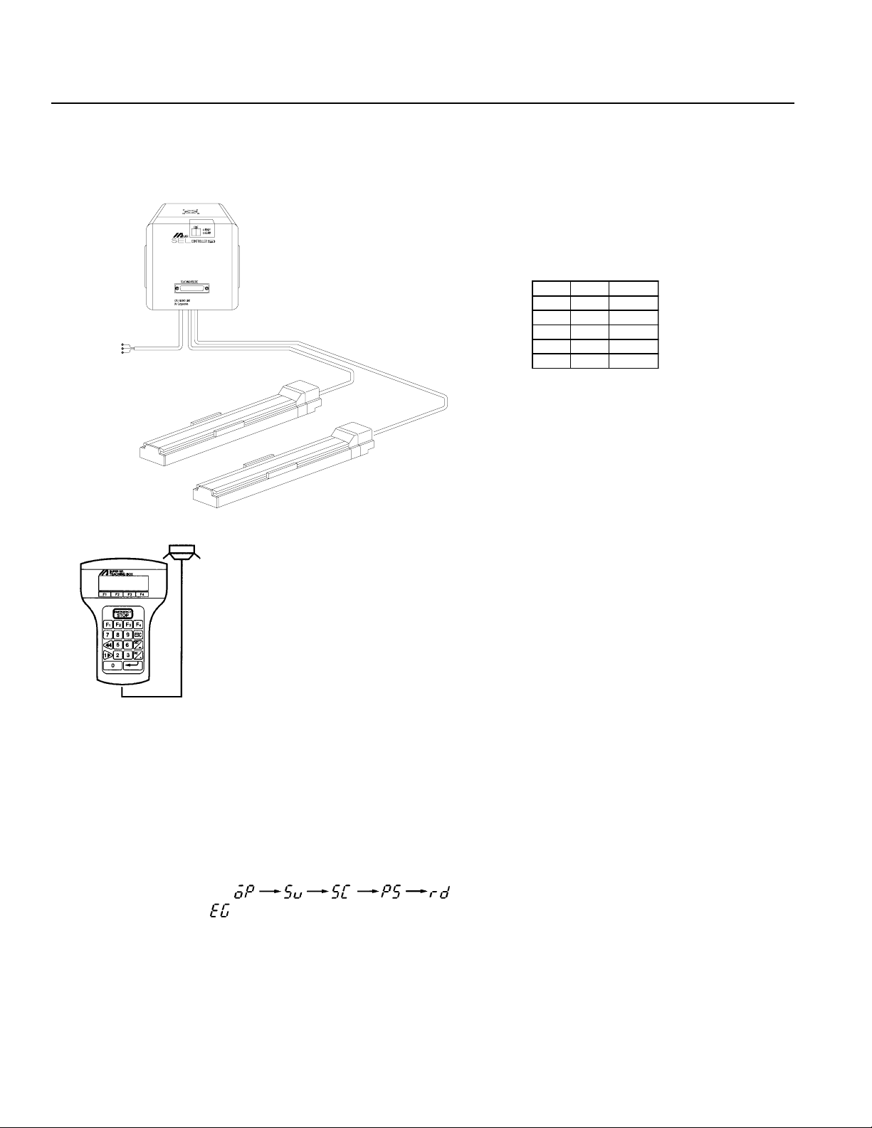
1. Connecting the IA Controller and Actuator
* Since Type E and T ype G Controllers are designed to be mounted
inside of a control panel, no plug is provided for the power cable
on the other end of the controller.
*Power Cable·Terminal
No. C olor S ignal
1 Black AC117V
2--- --3 W hite AC117V
4--- --5GreenFG
Teaching Pendant
Connect controller and actuator cables. Use only IA supplied cables. These cables include:
a. Motor cable
b. Encoder cable
c. Teaching pendant cable
d. Brake cable (optional)
e. Limit switch cable (optional)
Connect the power cord.
The CODE display shows in sequence. The Super SEL controller is ready to operate.
If the CODE display is release the Emergency Stop input.
Note: The Emergency Stop is normally closed (b contact point input). In order to release the emergency stop, short the jumper
post (ST1) at the bottom of the controller CPU UNIT or CPU SERVO UNIT with the jumper pin. Refer to Supplement
6 for the actual procedure.
Page 28
Page 31

Chapter 1. Setting Up
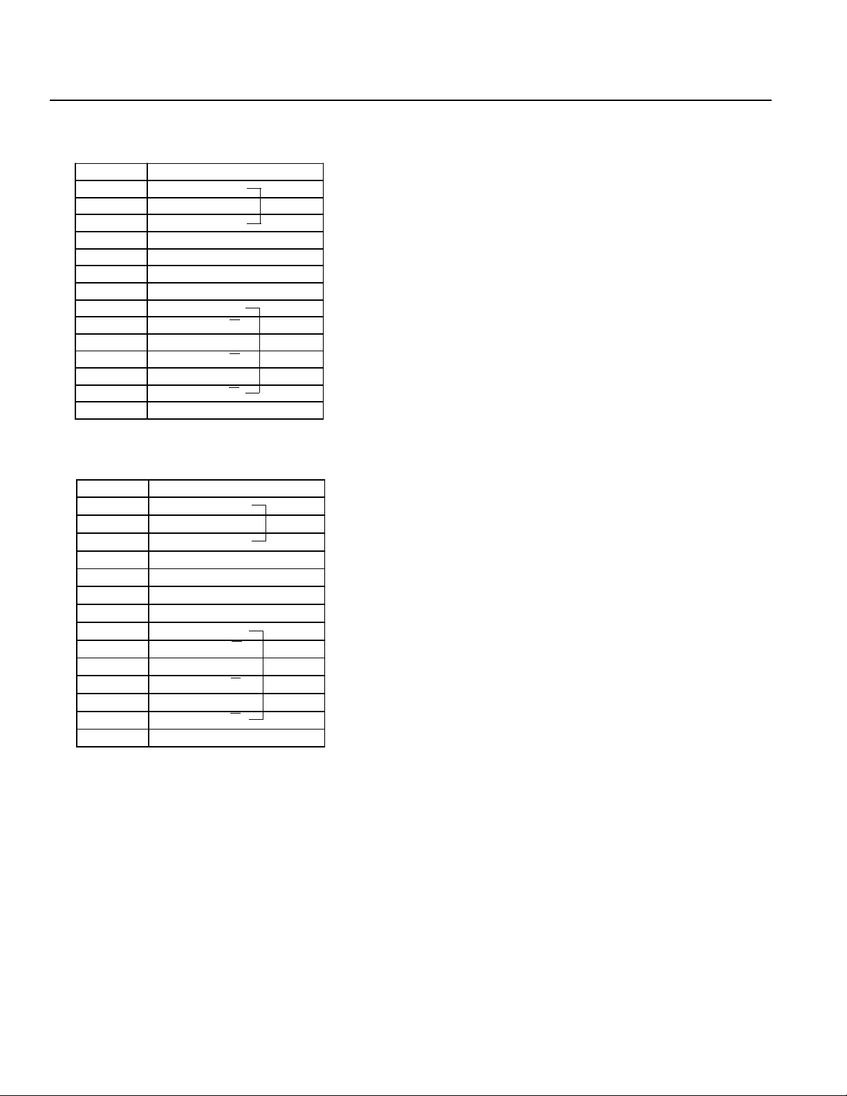
2. Interface List
I/O Connector (NPN-Sinking)
Pin No. Category Port No. Function Cable
1A P24 --- 1-Brown
1B
2A 001 User Input 1-Orange
2B 002 Emergency Stop b Contact Input * 1-Yellow
3A 003 SystemReserve 1-Green
3B 004 SystemReserve 1-Blue
4A 005 User Input 1-Purple
4B 006 User Input 1-Gray
5A 007 User Input 1-White
5B 008 PRG No. 1 (User Input) 1-Black
6A 009 PRG No. 2 (User Input) 2-Brown
6B 010 PRG No. 4 (User Input) 2-Red
7A 011 PRG No. 8 (User Input) 2-Orange
7B 012 PRG No. 10 (User Input) 2-Yellow
8A 013 PRG No. 20 (User Input) 2-Green
8B 014 PRG No. 40 (User Input) 2-Blue
9A 015 User Input 2-Purple
9B 016 User Input 2-Gray
10A 017 User Input 2-White
10B 018 User Input 2-Black
11A 019 User Input 3-Brown
11B 020 User Input 3-Red
12A 021 User Input 3-Orange
12B 022 User Input 3-Yellow
13A 023 User Input 3-Green
13B
14A 30 1 Ready Output 3-Purple
14B 302 User Output 3-Gray
15A 303 User Output 3-White
15B 304 User Output 3-Black
16A 305 User Output 4-Brown
16B 306 User Output 4-Red
17A 30 7 User Output 4-Orange
17B 308 User Output 4-Yellow
18A 309 User Output 4-Green
18B 310 User Output 4-Blue
19A 311 User Output 4-Purple
19B 312 User Output 4-Gray
20A 313 User Output 4-White
20B 314 User Output 4-Black
21A 315 User Output 5-Brown
21B 316 User Output 5-Red
22A 31 7 User Output 5-Orange
22B 318 User Output 5-Yellow
23A 319 User Output 5-Green
23B 320 User Output 5-Blue
24A 321 User Output 5-Purple
24B 322 User Output 5-Gray
25A 323 User Output 5-White
25B N24 --- 5-Black
Input
Output
000 External Start Input 1-Red
300 Em ergency Stop /Alarm Outp ut 3-Blue
* Emergency Stop (normally
closed). T o release the emergency stop, short circuit the
jumper post with a jumper pin or
connect pin 2B and pin 25B.
Refer to Supplement 6.
* Pin No.3A (Port No.003) and Pin
No.3B (Port No.004) cannot be
used as user input.
* Connector:
Sumitomo 3M7950-6500SC or
Yamaichi F AP-5001-1202
Page 29
Page 32

Chapter 1. Setting UpChapter 1. Setting Up
Caution ! NPN I/O wirings and PNP wirings are DIFFERENT
3. I/O Wiring Diagram
Standard I/O (NPN - Sinking)
Pin No. Category Port No. Functio n
1A P24 --1B
2A 001 User Input
2B 002 Emergency Stop b Contact Input *
3A 003 S ystemR eserve
3B 004 S ystemR eserve
4A 005 User Input
4B 006 User Input
5A 007 User Input
5B 008 P RG N o. 1 (User Input)
6A 009 P RG N o. 2 (User Input)
6B 010 P RG N o. 4 (User Input)
7A 011 P RG N o. 8 (User Input)
7B 012 PRG No. 10 (User Input)
8A 013 PRG No. 20 (User Input)
8B 014 PRG No. 40 (User Input)
9A 015 User Input
9B 016 User Input
10A 017 User Input
10B 018 User Input
11A 019 User Input
11B 030 User Input
12A 021 User Input
12B 022 User Input
13A 023 User Input
13B
14A 301 Ready Output
14B 302 User Output
15A 303 User Output
15B 304 User Output
16A 305 User Output
16B 306 User Output
17A 307 User Output
17B 308 User Output
18A 309 User Output
18B 310 User Output
19A 311 User Output
19B 312 User Output
20A 313 User Output
20B 314 User Output
21A 315 User Output
21B 316 User Output
22A 317 User Output
22B 318 User Output
23A 319 User Output
23B 320 User Output
24A 321 User Output
24B 322 User Output
25A 323 User Output
25B N24 ---
Input
Output
000 External Start Input
300 Em ergency Stop/Alarm O utput
External 24V power
R
W
RY
∆
SV
∆
P24
0
•
•
•
•
•
Digital SW
•
•
G
RY
∆
SV
∆
•
•
•
•
•
•
•
•
Note:The same cable colors
are used for the standard
cables and the expansion cables.
*Standard I/O Pin No.3A
(Port No.003), and Pin
No.3B(Port No.004) cannot be used as user
puts.
•
in-
Page 30
Page 33

Chapter 1. Setting Up
Expansion I/O * (NPN - Sinking)
Pin No. Category Port No. Function
1A P24 External Power Supply +24V Input
1B
2A 025 User Input
2B 026 User Input
3A 027 User Input
3B 028 User Input
4A 029 User Input
4B 030 User Input
5A 031 User Input
5B 032 User Input
6A 033 User Input
6B 034 User Input
7A 035 User Input
7B 036 User Input
8A 037 User Input
8B 038 User Input
9A 039 User Input
9B 040 User Input
10A 041 User Input
10B 042 User Input
11A 043 User Input
11B 044 User Input
12A 045 User Input
12B 046 User Input
13A 047 User Input
13B
14A 325 User Output
14B 326 User Output
15A 327 User Output
15B 328 User Output
16A 329 User Output
16B 330 User Output
17A 331 User Output
17B 332 User Output
18A 333 User Output
18B 334 User Output
19A 335 User Output
19B 336 User Output
20A 337 User Output
20B 338 User Output
21A 339 User Output
21B 340 User Output
22A 341 User Output
22B 342 User Output
23A 343 User Output
23B 344 User Output
24A 345 User Output
24B 346 User Output
25A 347 User Output
25B N24 E xternal Pow er Supply 0V
* This is the first expansion I/O. In the second expansion I/O,
the port numbers continue on from these numbers.
Input
Output
024 User Input
324 User Output
External 24V power
P24
0
•
•
•
•
•
•
Page 31
Page 34

Chapter 1. Setting Up
4. Interface List (PNP Sourcing)
Pin No. Category Port No. Function C able Color
1A N24 External power 0V 1-Brown
1B
2A 001 User input 1-Orange
2B 002 E mergency Stop b contact input *1 1-Yellow
3A 003 System reserve 1-Green
3B 004 System reserve 1-Blue
4A 005 User input 1-Purple
4B 006 User input 1-Gray
5A 007 User input 1-W hite
5B 008 P RG No. 1 (user input) 1-Black
6A 009 P RG No. 2 (user input) 1-Brown
6B 010 P RG No. 4 (user input) 2-Red
7A 011 PRG No. 8 (user input) 2-Orange
7B 012 PRG N o. 10 (user input) 2-Yellow
8A 013 PRG N o. 20 (user input) 2-Green
8B 014 PRG N o. 40 (user input) 2-Blue
9A 015 User input 2-Purple
9B 016 User input 2-Gray
10A 017 User input 2-White
10B 018 User input 2-Black
11A 019 User input 3-Brown
11B 020 User input 3-Red
12A 021 User input 3-Orange
12B 022 User input 3-Yellow
13A 023 User input 3-Green
13B
14A 301 Ready output 3-Purple
14B 302 Use r output 3-Gray
15A 303 Use r output 3-White
15B 304 Use r output 3-Black
16A 305 Use r output 4-Brown
16B 306 Use r output 4-Red
17A 307 Use r output 4-Orange
17B 308 Use r output 4-Yellow
18A 309 Use r output 4-Green
18B 310 Use r output 4-Blue
19A 311 Use r output 4-Purple
19B 312 Use r output 4-Gray
20A 313 Use r output 4-White
20B 314 Use r output 4-Black
21A 315 Use r output 5-Brown
21B 316 Use r output 5-Red
22A 317 Use r output 5-Orange
22B 318 Use r output 5-Yellow
23A 319 Use r output 5-Green
23B 320 Use r output 5-Blue
24A 321 Use r output 5-Purple
24B 322 Use r output 5-Gray
25A 323 Use r output 5-White
25B P24 External power +24V 5-Black
Input
Output
000 External start input 1-Red
300 Emergency stop/Alarm output 3-Blue
Emergency Stop is a b-contact in-
*
put (normally closed). To release
the emergency stop, short circuit
the jumper post with the jumper pin.
Refer to Supplement 7.
Pin No.3A (Port No.003), and Pin
*
No.3B (Port No.004) cannot be used
as user inputs.
Connector: Sumitomo 3M 7950-
*
6500SC or Yamaichi FAP-5001-
1202.
Page 29-A
Page 35

Chapter 1. Setting Up
5. Wiring Diagram
Pin No. Category Port No. Function Cable Color
1A N24 External power 0V 1-Brown
1B
2A 001 User input 1-Orange
2B 002 Emergency Stop b contact input 1-Yellow
3A 00 3 Sy stem re serv e 1-G reen
3B 004 System reserve 1-Blue
4A 005 User input 1-Purple
4B 006 User input 1-Gray
5A 007 User input 1-W hite
5B 008 PRG No. 1 (user input) 1-Black
6A 009 PRG No. 2 (user input) 1-Brown
6B 010 PRG No. 4 (user input) 2-Red
7A 011 PR G No. 8 (user input) 2-Orange
7B 012 PRG No . 10 (user input) 2-Yellow
8A 013 PR G No. 20 (user input) 2-Green
8B 014 PR G No. 40 (user input) 2-Blue
9A 015 User input 2-Purple
9B 016 User input 2-Gray
10A 017 User input 2-White
10B 018 User input 2-Black
11A 019 User input 3-Brown
11B 020 User input 3-Red
12A 021 User input 3-Orange
12B 022 User input 3-Yellow
13A 023 User input 3-Green
13B
14A 301 Ready output 3-Purple
14B 302 U ser output 3-Gray
15A 303 U ser output 3-White
15B 304 U ser output 3-Black
16A 305 U ser output 4-Brown
16B 306 U ser output 4-Re d
17A 307 U ser output 4-Orange
17B 308 U ser output 4-Yellow
18A 309 U ser output 4-Green
18B 310 U ser output 4-Blue
19A 311 U ser output 4-Purple
19B 312 U ser output 4-Gray
20A 313 U ser output 4-White
20B 314 U ser output 4-Black
21A 315 U ser output 5-Brown
21B 316 U ser output 5-Re d
22A 317 U ser output 5-Orange
22B 318 U ser output 5-Yellow
23A 319 U ser output 5-Green
23B 320 U ser output 5-Blue
24A 321 U ser output 5-Purple
24B 322 U ser output 5-Gray
25A 323 U ser output 5-White
25B P24 External power +24V 5-Black
Note: The same cable colors are used for the standard cables and the expansion cables.
Inp ut
Output
000 External start input 1-Red
300 Emergency stop/Alarm output 3-Blue
Standard I/O (PNP - Sourcing)
*Standard I/O Pin No.3A (Port No.003), and Pin No.3B(Port No.004) cannot be used as user inputs.
R
W
RY
∇
SV
∇
BCD SW
G
RY
∇
SV
∇
P24
0
NOTE:
•
•
•
•
•
•
•
•
•
For the SEL EU controller, if the
motor/encoder cables are not connected to the controller, the controller will be in a permanent emergency stop condition (even if the Estop input is jumpered to 24VDC
for a PNP I/O board).
•
•
•
•
•
•
•
•
Page 30-A
Page 36

Chapter 1. Setting Up
I/O Expansion * (PNP-Sourcing)
Pin No. Category Port No. Function Cable Color
1A N24 External power 0V 1-Brown
1B
2A 025 User input 1-Orange
2B 026 User input 1-Yellow
3A 027 User input 1-Green
3B 028 User input 1-Blue
4A 029 User input 1-Purple
4B 030 User input 1-Gray
5A 031 User input 1-White
5B 032 User input 1-Black
6A 033 User input 1-Brown
6B 034 User input 2-Red
7A 035 User input 2-Orange
7B 036 User input 2-Yellow
8A 037 User input 2-Green
8B 038 User input 2-Blue
9A 039 User input 2-Purple
9B 040 User input 2-Gray
10A 041 User input 2-White
10B 042 User input 2-Black
11A 043 User input 3-Brown
11B 044 User input 3-Red
12A 045 User input 3-Orange
12B 046 User input 3-Yellow
13A 047 User input 3-Green
13B
14A 325 User output 3-Purple
14B 326 User output 3-Gray
15A 327 User output 3-White
15B 328 User output 3-Black
16A 329 User output 4-Brown
16B 330 User output 4-Red
17A 331 User output 4-Orange
17B 332 User output 4-Yellow
18A 333 User output 4-Green
18B 334 User output 4-Blue
19A 335 User output 4-Purple
19B 336 User output 4-Gray
20A 337 User output 4-White
20B 338 User output 4-Black
21A 339 User output 5-Brown
21B 340 User output 5-Red
22A 341 User output 5-Orange
22B 342 User output 5-Yellow
23A 343 User output 5-Green
23B 344 User output 5-Blue
24A 345 User output 5-Purple
24B 346 User output 5-Gray
25A 347 User output 5-White
25B P24 External power +24V 5-Black
* This is the first expansion I/O. In the second expansion I/O,
the port numbers continue on from these numbers.
Inpu t
Output
024 User input 1-Red
324 User output 3-Blue
Page 31-A
•
•
∇
•
•
•
P24
0
•
Page 37

Chapter 1. Setting Up
DC24V Electromagnetic Valve Wiring Precautions (Example)
Super SEL
I/O Unit
24V Switching Power
Cable size
0.75° or greater
Output Relay Circuit
Separate
Wiring should be a separate system
Large Voltage Electromagnetic V alve Circuit
In a situation where the I/O unit drives the relay and the relay drives the electromagnetic valve, separate the output relay
circuit and the large voltage electromagnetic valve circuit as shown in the diagram above.
Page 32
Page 38

Chapter 1. Setting Up
4. Teaching/RS232C Connector (D-Sub 25 DTE Special *)
Pin No. Signal
1 FG
2 TXD
3 RXD
4 (RTS)
5 (CTS)
6 DSR
7 SG
8 NC
9 NC
10 NC
11 NC
12 NC
13 NC
Pin No. Signal
14 NC
15 NC
16 NC
17 NC
18 +6.2V Output
19 NC
20 DTR
21 NC
22 NC
23
Emergency Stop
Switch (EMG.SW)
24 NC
25 0V (+6.2V)
*
*
*
* Pin numbers 18, 23, and 25 are for use with the teaching pendant signal. Do not connect these pins.
• Pin numbers 4 and 5 are short-circuited.
nn
nRS232C Cable
nn
Use RS232C cable pin configuration (between controller and computer serial port)
RS232C Adapter
(25 Pin Male)
1
Shield
l
Earth
2
l
TXD
3
l
RXD
4
l
RTS
5
l
CTS
6
l
DSR
7
l
GND
20
l
DTR
IBM PC
(9 Pin Female)
l
2
l
3
l
4
l
5
l
6
l
7
l
8
l
Earth
RXD
TXD
DTR
GND
DSR
RTS
CTS
RS232C Adapter
(25 Pin Male)
1
l
Earth
2
l
TXD
3
l
RXD
4
l
RTS
5
l
CTS
6
l
DSR
7
l
GND
20
ll
DTR
IBM PC
(25 Pin Female)
1
l
2
l
3
l
4
l
5
l
6
l
7
l
20
Earth
TXD
RXD
RTS
CTS
DSR
GND
DTR
Page 33
Page 39

Chapter 1. Setting Up
5. Connector Pin Assignment
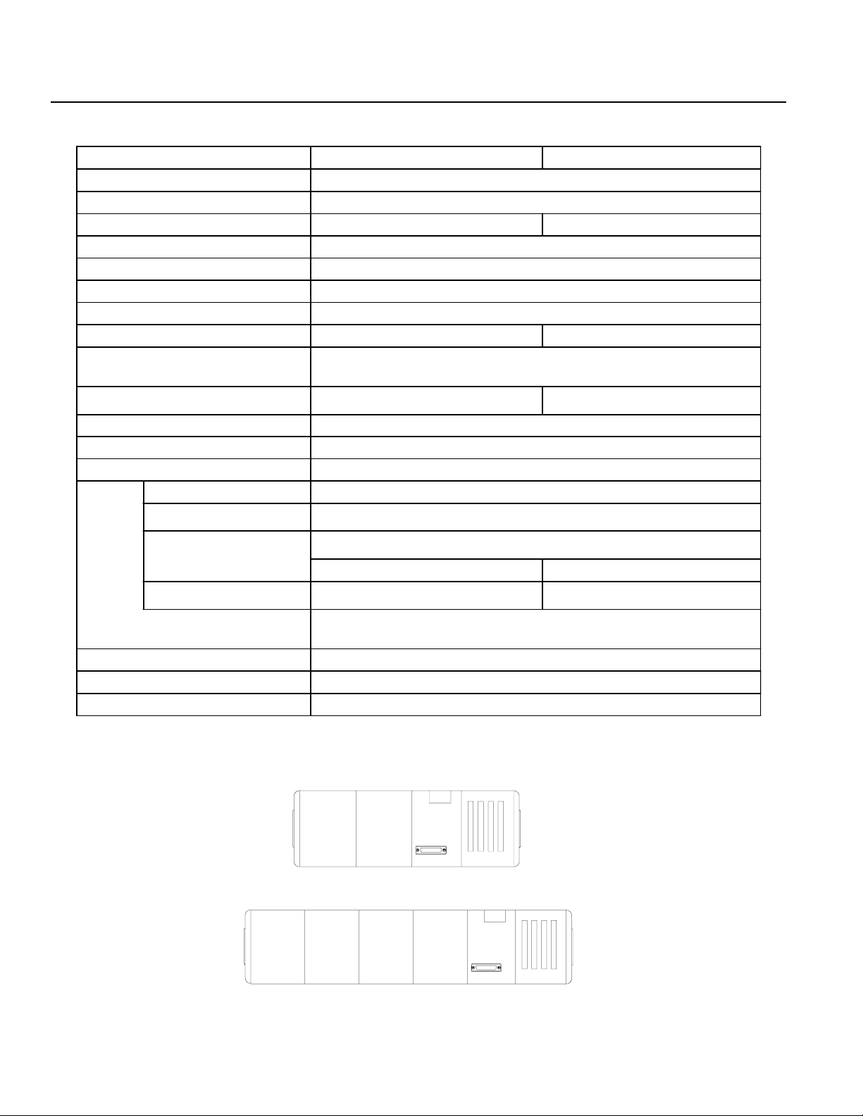
The bottom view of the Super SEL Type E/G on the left shows the placement of the connectors. Please refer to Page 29 and
31 for the I/O connector and the I/O wiring (including the I/O expansion).
The connector pin assignment for the other parts are shown below.
(1) AC100W 2-Axis specifications
Power Supply Connector
Pin No. Signal
1AC117V
3AC117V
5FG
Nippon Molex 53265-0320 (3P) (Body side)
51067-0500 Housing (5P)
50217-8100 x 3 Terminal
LS Connector (Option)
Pin No. Signal
1P24V
2N
3XLS
4YLS
5 E MG stop contact point input*
* The Emergency Stop is normally open.
BK Connector (Option)
Pin No. Signal
160V
2GD
3 XBK
4 YBK
M·PG Connector (Motor/Encoder Signal)
Pin No. Signal
1U
2V
3W
4NC
5FG
6 PV5
7GD
8A
9A
10 B
11 B
12 Z
13 Z
14 FG
X (1) Axis
X (1) Axis
Nippon Molex 53258-0520 (5P) (Body side)
51067-0500 Housing (5P)
50217-8100 x 5 Terminal
Nippon Molex 53258-0420 (4P) (Body side)
51067-0500 Housing (4P)
50217-8100 x 4 Terminal
Nippon Molex 53258-1420 (14P) (Body side)
51067-1400 Housing (14P)
50217-8100 x 14 Terminal
Page 34
Page 40

Chapter 1. Setting Up
M·PG Connector (Motor/Encoder Signal)
Pin No. Signal
1U
2V
3W
4NC
5FG
6 PV5
7GD
8A
9A
10 B
11 B
12 Z
13 Z
14 FG
SEL NET SND Connector (Option)
Pin No. Signal
1NC
2NC
3RD
4TD
5GD
6FG
Y (2) Axis
Y (2) Axis
Nippon Molex 53258-1420 (14P) (Body side)
51067-1400 Housing (14P)
50217-8100 x 14 Terminal
Nippon Molex 53259-0620 (6P) (Body side)
51067-0600 Housing (6P)
50217-8100 x 6 Terminal
SEL NET RCV Connector (Option)
Pin No. Signal
1NC
2NC
3RD
4TD
5GD
6FG
Nippon Molex 53259-0620 (6P) (Body side)
51067-0600 Housing (6P)
50217-8100 x 6 Terminal
Page 35
Page 41

Chapter 1. Setting Up
(2) AC100W 4-Axis specifications
Power Supply Connector
Pin No. Signal
1AC117V
3AC117V
5FG
Nippon Molex 53265-0320 (3P) (Body side)
51067-0500 Housing (5P)
50217-8100 x 3 Terminal
LS Connector (Option)
Pin No. Signal
1P24V
2N
3XLS
4YLS
5 EM G stop contact point input*
* The Emergency Stop is normally open.
LS Connector (Option)
Pin No. Signal
1P24V
2N
3ZLS
4
5 EM G stop contact point input*
* The Emergency Stop is normally open.
θ
LS
BK Connector (Option)
Pin No. Signal
1 60V
2GD
3 XBK
4 YBK
Nippon Molex 53258-0520 (5P) (Body side)
51067-0500 Housing (5P)
50217-8100 x 5 Terminal
Nippon Molex 53258-0520 (5P) (Body side)
51067-0500 Housing (5P)
50217-8100 x 5 Terminal
Nippon Molex 53258-0420 (4P) (Body side)
51067-0400 Housing (4P)
50217-8100 x 4 Terminal
Page 36
Page 42

Chapter 1. Setting Up
BK Connector (Option)
Pin No. Signal
160V
2GD
3 XBK
4
M·PG Connector (Motor/Encoder Signal)
θ
BK
Nippon Molex 53258-0420 (4P) (Body side)
51067-0400 Housing (4P)
50217-8100 x 4 Terminal
Pin No. Signal
1U
2V
3W
4NC
5FG
6 PV5
7GD
8A
9A
10 B
11 B
12 Z
13 Z
14 FG
X (1) Axis
X (1) Axis
M·PG Connector (Motor/Encoder Signal)
Pin No. Signal
1U
2V
3W
4NC
5FG
6 PV5
7GD
8A
9A
10 B
11 B
12 Z
13 Z
14 FG
Y (2) Axis
Y (2) Axis
Nippon Molex 53258-1420 (14P) (Body side)
51067-1400 Housing (14P)
50217-8100 x 14 Terminal
Nippon Molex 53258-1420 (14P) (Body side)
51067-1400 Housing (14P)
50217-8100 x 14 Terminal
Page 37
Page 43
Chapter 1. Setting Up
M·PG Connector (Motor/Encoder Signal)
Pin No. Signal
1U
2V
3W
4NC
5FG
6 PV5
7GD
8A
9A
10 B
11 B
12 Z
13 Z
14 FG
Z (3) Axis
Z (3) Axis
M·PG Connector (Motor/Encoder Signal)
Pin No. Signal
1U
2V
3W
4NC
5FG
6 PV5
7GD
8A
9A
10 B
11 B
12 Z
13 Z
14 FG
θ (4) Axis
θ (4) Axis
Nippon Molex 53258-1420 (14P) (Body side)
51067-1400 Housing (14P)
50217-8100 x 14 Terminal
Nippon Molex 53258-1420 (14P) (Body side)
51067-1400 Housing (14P)
50217-8100 x 14 Terminal
Page 38
Page 44

Chapter 1. Setting Up
(3) AC200W 2-Axis specifications
Power Supply Connector
Pin No. Signal
1AC117V
3AC117V
5FG
Nippon Molex 53265-0320 (3P) (Body side)
51067-0500 Housing (5P)
50217-8100 x 3 Terminal
LS Connector (Option)
Pin No. Signal
1P24V
2N
3XLS
4YLS
5 EM G stop contact point input*
* The Emergency Stop is normally open.
BK Connector (Option)
Pin No. Signal
160V
2GD
3 XBK
4 YBK
Nippon Molex 53258-0520 (5P) (Body side)
51067-0500 Housing (5P)
50217-8100 x 5 Terminal
Nippon Molex 53258-0420 (4P) (Body side)
51067-0400 Housing (4P)
50217-8100 x 4 Terminal
Page 39
Page 45

Chapter 1. Setting Up
M·PG Connector (Motor/Encoder Signal)
Pin No. Signal
1U
2V
3W
4NC
5FG
6 PV5
7GD
8A
9A
10 B
11 B
12 Z
13 Z
14 FG
X (1) Axis
X (1) Axis
M·PG Connector (Motor/Encoder Signal)
Pin No. Signal
1U
2V
3W
4NC
5FG
6 PV5
7GD
8A
9A
10 B
11 B
12 Z
13 Z
14 FG
Y (2) Axis
Y (2) Axis
Nippon Molex 53258-1420 (14P) (Body side)
51067-1400 Housing (14P)
50217-8100 x 14 Terminal
Nippon Molex 53258-1420 (14P) (Body side)
51067-1400 Housing (14P)
50217-8100 x 14 Terminal
Page 40
Page 46

Chapter 1. Setting Up
(4) AC400W 1-Axis specifications
Power Supply Connector
Pin No. Signal
1AC117V
3AC117V
5FG
LS Connector (Option)
Pin No. Signal
1P24V
2N
3XLS
4YLS
5 EM G stop contact point input*
* The Emergency Stop is normally open.
Nippon Molex 53265-0320 (3P) (Body side)
51067-0500 Housing (5P)
50217-8100 x 3 Terminal
Nippon Molex 53258-0520 (5P) (Body side)
51067-0500 Housing (5P)
50217-8100 x 5 Terminal
BK Connector (Option)
Pin No. Signal
160V
2GD
3 XBK
4 YBK
M·PG Connector (Motor/Encoder Signal)
Pin No. Signal
1U
2V
3W
4NC
5FG
6 PV5
7GD
8A
9A
10 B
11 B
12 Z
13 Z
14 FG
X (1) Axis
X (1) Axis
Nippon Molex 53258-0420 (4P) (Body side)
51067-0400 Housing (4P)
50217-8100 x 4 Terminal
Nippon Molex 53258-1420 (14P) (Body side)
51067-1400 Housing (14P)
50217-8100 x 14 Terminal
Page 41
Page 47

Chapter 1. Setting Up
(5) DC100W 2-Axis specifications
Power Supply Connector
Pin No. Signal
1AC117V
3AC117V
5FG
LS Connector (Option)
Pin No. Signal
1P24V
2N
3XLS
4YLS
5 EM G stop contact point inpu t*
* The Emergency Stop is normally open.
Nippon Molex 53265-0320 (3P) (Body side)
51067-0500 Housing (5P)
50217-8100 x 3 Terminal
Nippon Molex 53258-0520 (5P) (Body side)
51067-0500 Housing (5P)
50217-8100 x 5 Terminal
BK Connector (Option)
Pin No. Signal
160V
2GD
3 XBK
4 YBK
M·PG Connector (Motor/Encoder Signal)
Pin No. Signal
1MB
2MB
3MA
4MA
5FG
6 PV5
7GND
8A
9AGND
10 B
11 BGND
12 Z
13 ZGND
14 FG
X (1) Axis
X (1) Axis
Nippon Molex 53258-0420 (4P) (Body side)
51067-0500 Housing (4P)
50217-8100 x 4 Terminal
Nippon Molex 53258-1420 (14P) (Body side)
51067-1400 Housing (14P)
50217-8100 x 14 Terminal
Page 42
Page 48

Chapter 1. Setting Up
M·PG Connector (Motor/Encoder Signal)
Pin No. Signal
1MB
2NC
3NC
4MA
5FG
6 PV5
7GD
8A
9AGND
10 B
11 BGND
12 Z
13 ZGND
14 FG
Y (2) Axis
Y (2) Axis
SEL NET SND Connector (Option)
Pin No. Signal
1NC
2NC
3RD
4TD
5GD
6FG
Nippon Molex 53258-1420 (14P) (Body side)
51067-1400 Housing (14P)
50217-8100 x 14 Terminal
Nippon Molex 53259-0620 (6P) (Body side)
51067-0600 Housing (6P)
50217-8100 x 6 Terminal
SEL NET RCV Connector (Option)
Pin No. Signal
1NC
2NC
3RD
4TD
5GD
6FG
Nippon Molex 53259-0620 (6P) (Body side)
51067-0600 Housing (6P)
50217-8100 x 6 Terminal
Page 43
Page 49

Chapter 1. Setting Up
(6) DC100W 4-Axis specifications
Power Supply Connector
Pin No. Signal
1AC117V
3AC117V
5FG
Nippon Molex 53265-0320 (3P) (Body side)
51067-0500 Housing (5P)
50217-8100 x 3 Terminal
LS Connector (Option)
Pin No. Signal
1P24V
2N
3XLS
4YLS
5 EM G stop contact point input*
* The Emergency Stop is normally open.
LS Connector (Option)
Pin No. Signal
1P24V
2N
3ZLS
4
5 EM G stop contact point input*
* The Emergency Stop is normally open.
θ
LS
BK Connector (Option)
Pin No. Signal
1 60V
2GD
3 XBK
4 YBK
Nippon Molex 53258-0520 (5P) (Body side)
51067-0500 Housing (5P)
50217-8100 x 5 Terminal
Nippon Molex 53258-0520 (5P) (Body side)
51067-0500 Housing (5P)
50217-8100 x 5 Terminal
Nippon Molex 53258-0420 (4P) (Body side)
51067-0400 Housing (4P)
50217-8100 x 4 Terminal
Page 44
Page 50

Chapter 1. Setting Up
BK Connector (Option)
Pin No. Signal
160V
2GD
3ZBK
4
θ
BK
M·PG Connector (Motor/Encoder Signal)
Pin No. Signal
1MB
2NC
3NC
4MA
5FG
6 PV5
7GD
8A
9AGND
10 B
11 BGND
12 Z
13 ZGND
14 FG
X (1) Axis
X (1) Axis
Nippon Molex 53258-0420 (4P) (Body side)
51067-0400 Housing (4P)
50217-8100 x 4 Terminal
Nippon Molex 53258-1420 (14P) (Body side)
51067-1400 Housing (14P)
50217-8100 x 14 Terminal
M·PG Connector (Motor/Encoder Signal)
Pin No. Signal
1MB
2NC
3NC
4MA
5FG
6 PV5
7GD
8A
9AGND
10 B
11 BGND
12 Z
13 ZGND
14 FG
Y (2) Axis
Y (2) Axis
Nippon Molex 53258-1420 (14P) (Body side)
51067-1400 Housing (14P)
50217-8100 x 14 Terminal
Page 45
Page 51
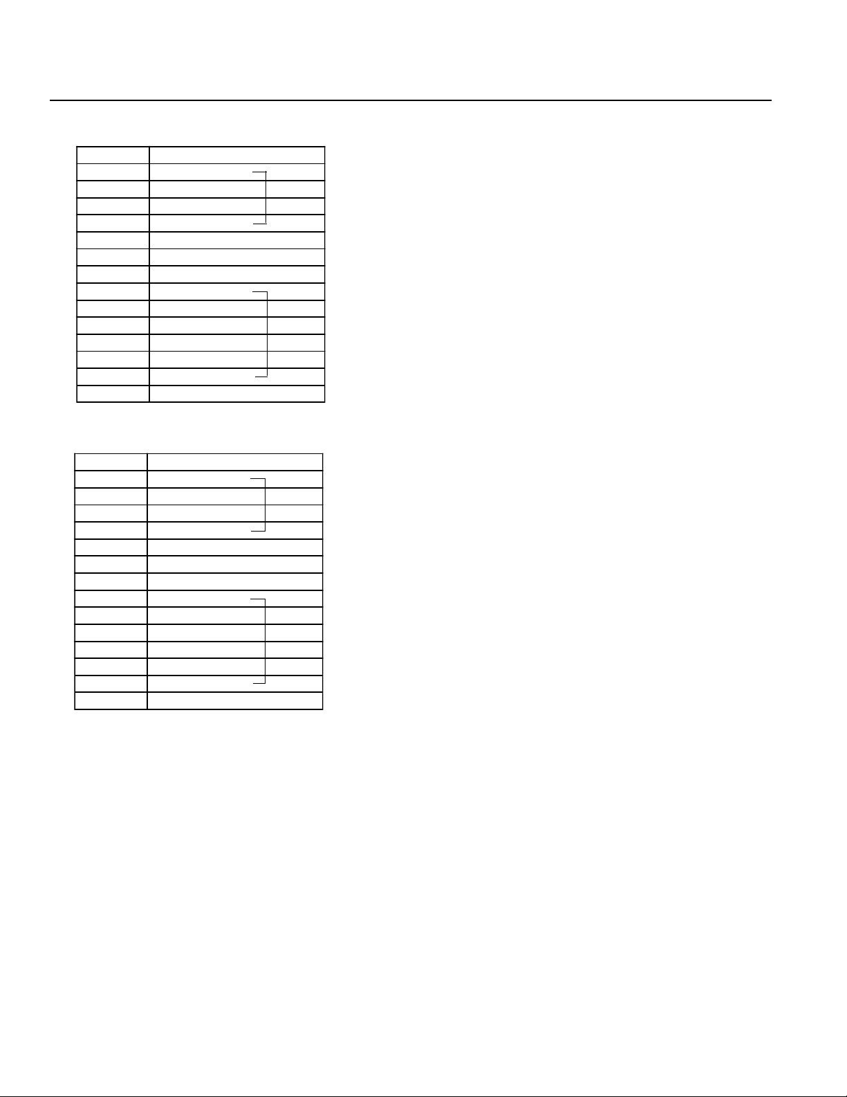
Chapter 1. Setting Up
M·PG Connector (Motor/Encoder Signal)
Pin No. Signal
1MB
2NC
3NC
4MA
5FG
6 PV5
7GD
8A
9AGND
10 B
11 BGND
12 Z
13 ZGND
14 FG
M·PG Connector (Motor/Encoder Signal)
Pin No. Signal
1MB
2NC
3NC
4MA
5FG
6 PV5
7GD
8A
9AGND
10 B
11 BGND
12 Z
13 ZGND
14 FG
Z (3) Axis
Z (3) Axis
θ (4) Axis
θ (4) Axis
Nippon Molex 53258-1420 (14P) (Body side)
51067-1400 Housing (14P)
50217-8100 x 14 Terminal
Nippon Molex 53258-1420 (14P) (Body side)
51067-1400 Housing (14P)
50217-8100 x 14 Terminal
Page 46
Page 52

Chapter 1. Setting Up
(7) DC200W 2-Axis specifications
Power Supply Connector
Pin No. Signal
1AC117V
3AC117V
5FG
Nippon Molex 53265-0320 (3P) (Body side)
51067-0500 Housing (5P)
50217-8100 x 3 Terminal
LS Connector (Option)
Pin No. Signal
1P24V
2N
3XLS
4YLS
5 EM G stop contact point input*
* The Emergency Stop is normally open.
BK Connector (Option)
Pin No. Signal
160V
2GD
3 XBK
4 YBK
Nippon Molex 53258-0520 (5P) (Body side)
51067-0500 Housing (5P)
50217-8100 x 5 Terminal
Nippon Molex 53258-0420 (4P) (Body side)
51067-0400 Housing (4P)
50217-8100 x 4 Terminal
Page 47
Page 53

Chapter 1. Setting Up
M·PG Connector (Motor/Encoder Signal)
Pin No. Signal
1MB
2NC
3NC
4MA
5FG
6 PV5
7GD
8A
9AGND
10 B
11 BGND
12 Z
13 ZGND
14 FG
M·PG Connector (Motor/Encoder Signal)
Pin No. Signal
1MB
2NC
3NC
4MA
5FG
6 PV5
7GD
8A
9AGND
10 B
11 BGND
12 Z
13 ZGND
14 FG
X (1) Axis
X (1) Axis
Y (2) Axis
Y (2) Axis
Nippon Molex 53258-1420 (14P) (Body side)
51067-1400 Housing (14P)
50217-8100 x 14 Terminal
Nippon Molex 53258-1420 (14P) (Body side)
51067-1400 Housing (14P)
50217-8100 x 14 Terminal
Page 48
Page 54

Chapter 1. Setting Up
6. Controller Dimensions
Type E (Single Axis)
AC 60W • 100W
DC 20W ~ 100W
Type G (2 Axis)
AC 60W • 100W x 2
DC 20W ~ 100W x 2
Front View Side View
Type E (Single Axis) + Expansion Unit Box (Option)
AC 60W • 100W
DC 20W ~ 100W
Type G (2 Axis) + Expansion Unit Box (Option)
AC 60W • 100W x 2
DC 20W ~ 100W x 2
Front View Side View
Page 49
Page 55

Chapter 1. Setting Up
Type E (Single Axis)
AC 200W
AC 400W
DC 200W
Type G (2 Axis)
AC 200W x 2
DC 200W x 2
Type G (4 Axis)
AC 60W • 100W x 4
DC 20W ~ 100W x 4
Front View Side View
Type G (2 Axis)
AC 400W
Type G (2 Axis)
AC 200W x 4
DC 200W x 4
Front View Side View
Page 50
Page 56

Chapter 1. Setting Up
Type G (4 Axis)
AC 400W x 4
Front View Side View
Type G (8 Axis)
AC 60W • 100W x 4
DC 20W ~ 100W x
Type G (8 Axis)
AC 200W x 8
DC 200W x 8
Front View Side View
Front View Side View
Page 51
Page 57

Chapter 1. Setting Up
7. Unit Configurations
1 Servo Driver Units: Basic Modules
Module 1 - Both CPU and servo driver in a single unit. Representative of 1 or 2-axis Type-E and Type-G controllers with
100W maximum motor capacity per axis.
100W 2-axis dedicated
Module 2 - 4-axis servo driver unit with 100W maximum motor capacity per axis. This servo driver unit must be used
along with a separate CPU unit. (See examples)
Servo driver unit
(100W 4-axis)
Module 3 - 2-Axis servo driver unit with 200W maximum motor capacity per axis. This servo driver unit must be used
along with a separate CPU unit. (See examples)
Servo driver unit
(200W 2-axis)
Module 4 - 1-Axis servo driver unit with 400W motor capacity. This servo driver unit must be used along with a separate
CPU unit. (See examples)
Servo driver unit
(400W 1-axis)
Page 52
Page 58

Chapter 1. Setting Up
2 5-Axis configuration with various motor capacities
CPU Unit
Axis 1 =60W
Axis 2 =100W
Axis 3 =100W
Axis 4 =200W
∪
Axis 5 =60W
* The unit with the largest motor capacity is placed at the furthest left of the CPU unit. This is to reduce noise
interference. A 12-slot expansion unit is available as an option.
100W 4-axis servo driver unit
200W 2-axis servo driver unit (using 1 axis only)
+
+
Servo unit 200W 2 axis
(1 axis use)
Servo unit 100W 4 axis
(4 axis use)
CPU unit
4-slot expansion unit
3 3-Axis configuration with various motor capacities
CPU Unit
+
Axis 1 =200W
Axis 2 =60W
Axis 3 =60W
* The unit with the largest motor capacity is placed at the furthest left of the CPU unit. This is to reduce
200W 2-axis servo driver unit (using 1 axis only)
+
100W 4-axis servo driver unit (using 2 axes only)
noise interference.
Servo unit 200W 2 axis
(1 axis use)
Servo unit 100W 4axis
(2 axis use)
CPU unit
4-slot expansion unit
Page 53
Page 59
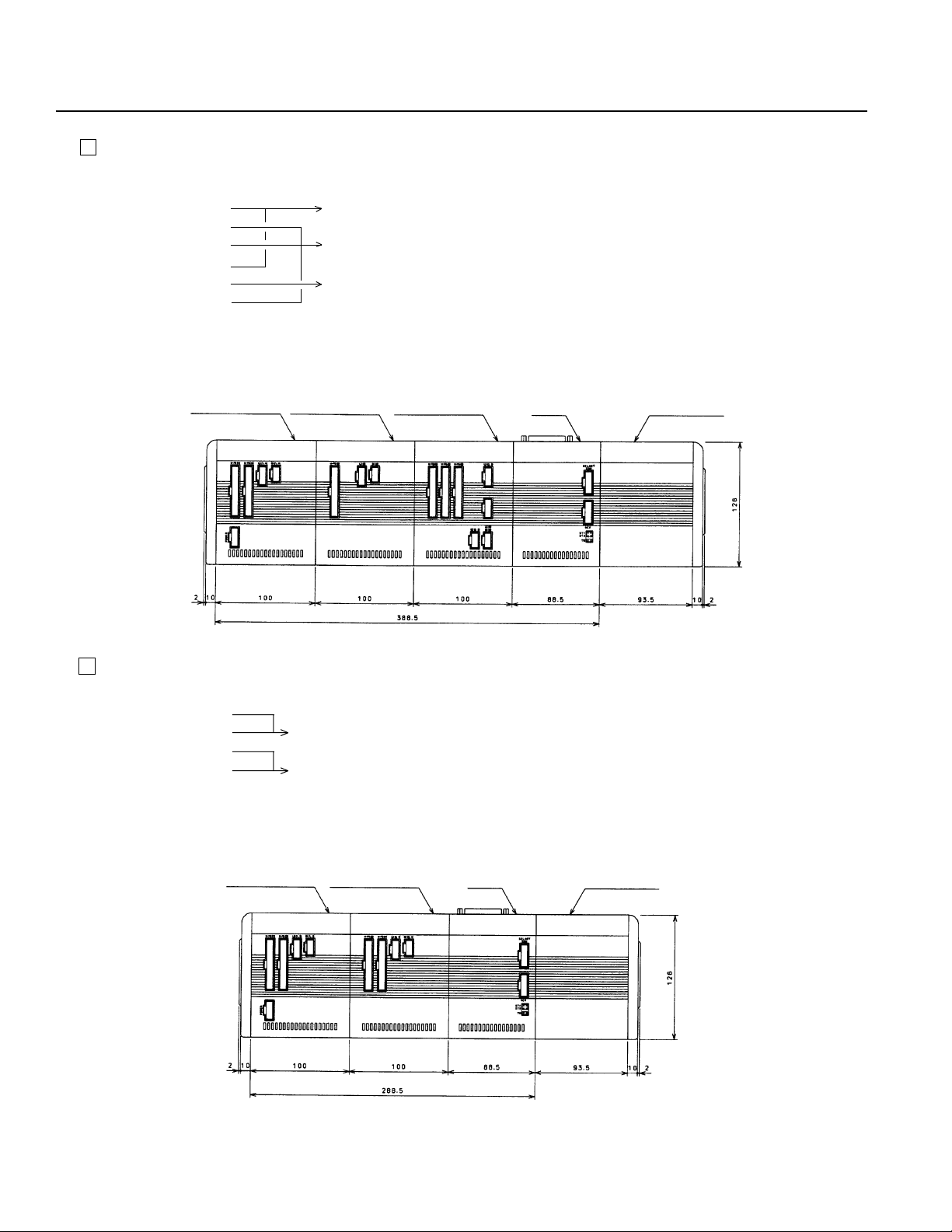
Chapter 1. Setting Up
4 6-Axis configuration with various motor capacities
Axis 1 =200W
Axis 2 =60W
Axis 3 =100W
Axis 4 =200W
Axis 5 =200W
Axis 6 =100W
* The unit with the largest motor capacity is placed at the furthest left of the CPU unit. This is to reduce noise
interference. A 12-slot expansion unit is available as an option.
∪
∪
∪
CPU Unit
+
200W 2-axis servo driver unit
+
100W 4-axis servo driver unit (using 3 axes only)
+
200W 2-axis servo driver unit (using 1 axis only)
Servo unit 200W 2 axis
(2 axis use)
Servo unit 200W 2 axis
(1 axis use)
Servo unit 100W 4 axis
(3 axis use)
CPU unit
4-slot expansion unit
5 4-Axis configuration with various motor capacities
CPU Unit
Axis 1 =200W
Axis 2 =200W
Axis 3 =200W
Axis 4 =100W
200W 2-axis servo driver unit
200W 2-axis servo driver unit
+
+
(Specification changes to 200W 1-axis and 100W 1-axis)
* The unit with the largest motor capacity is placed at the furthest left of the CPU unit. This is to reduce noise
interference.
Servo unit 200W 2 axis
(2 axis use)
Servo unit 200W 2 axis
(2 axis use)
CPU unit
Page 54
4-slot expansion unit
Page 60

Chapter 1. Setting Up
6 Controller configuration limitations
(1) Limitation on number of axes
Motor Capacity 100W (Maximum 8 axes)
Motor Capacity 200W (Maximum 8 axes)*
Motor Capacity 400W (Maximum 4 axes)*
* In the case of 8 axes with 200W motor or 4 axes with 400W motor, there are two power supply locations so power
must be supplied to both.
200W 8 Axis Specification
Servo unit
200W 2 axis
(2 axis use)
AC117V
400W 4 Axis Specification
Servo unit
400W 1 axis
Servo unit
200W 2 axis
(2 axis use)
Servo unit
400W 1 axis
Servo unit
200W 2 axis
(2 axis use)
Servo unit
400W 1 axis
Servo unit
200W 2 axis
(2 axis use)
Servo unit
400W 1 axis
CPU unit
CPU unit
4-slot expansion unit
4-slot expansion unit
AC 117V
(2) Limitation on axis expansion for dedicated 2-axis unit
The dedicated 2-axis Super SEL controller unit cannot be expanded to handle more than 2 axes.
(3) Limitation on unit configuration
Up to a maximum for four servo driver units can be connected.
[Example 1]
400W x 3 axes 3 units
+ = 4 units à ok
200W x 1 axis 1 unit
[Example 2]
400W x 3 axes 3 units
+ = 5 units à no good
200W x 3 axes 2 units
Page 55
Page 61

Chapter 1. Setting Up
8. Type G (AC) Unit Configurations
Once the axis alignment and motor wattage (60W, 100W, 200W, 400W) have been decided, the controller unit configuration
can be determined. We will explain the tables given below for determining the unit configuration from the model type.
Check how many axes there are by motor output. In this case,
1.
any motor output below 100W will be considered as 100W.
Example 200W - 100W - 60W
ò
200W x 1
100W x 2 ß60W is less than 100W so it is considered as 100W
Looking at the front of the unit, arrange the units with the largest
2.
output starting at the left, refer to charts 1 ~ 7 on the following
pages and confirm the configuration type.
EXAMPLE 1
2-axis system
200W-400W Assembly
Model type is M-SEL-G-2-AC-200-400 (1)
ê
200W x 1
400W x 1
Arrange from the largest output,
400 + 200
According to Table 1, the configuration type is C
Note: Because the unit is arranged in order of largest output, please be aware that the order in which
the axes are arranged may differ from what was specified at the time the unit was ordered (in
actual usage, there will be no changes to the specifications designated by the customer). However, for output under 100W , the units will be arranged in axis order regardless of the wattage.
○○○○
Page 56
Page 62

Chapter 1. Setting Up
EXAMPLE 2
4-axis system
60W-200W-100W-60W Assembly
Model type is M-SEL-G-4-AC-60-200-100-60
ê
100W x 3
200W x 1
Arrange from the largest output,
(200 x 1) + (100 x 3)
According to Table 3, the configuration type is C
EXAMPLE 3
6-axis system
400W-200W-400W-200W-100W-60W Assembly
Model type is M-SEL-G-6-AC-400-200-400-200-100-60
ê
400W x 2
200W x 2
100W x 2
Arrange from the largest output,
(400 x 2) + (200 x 2) + (100 x 2)
According to Table 5, the configuration type is H
*There are other limiting factors on the assembly types. When the total output is 1600W or less, up to a maximum of 4 servo driver
units can be connected. For an assembly consisting entirely of 400W output, only up to four axes can be assembled. Configurations where the above restrictions apply, are excluded from the tables that follow.
Page 57
Page 63
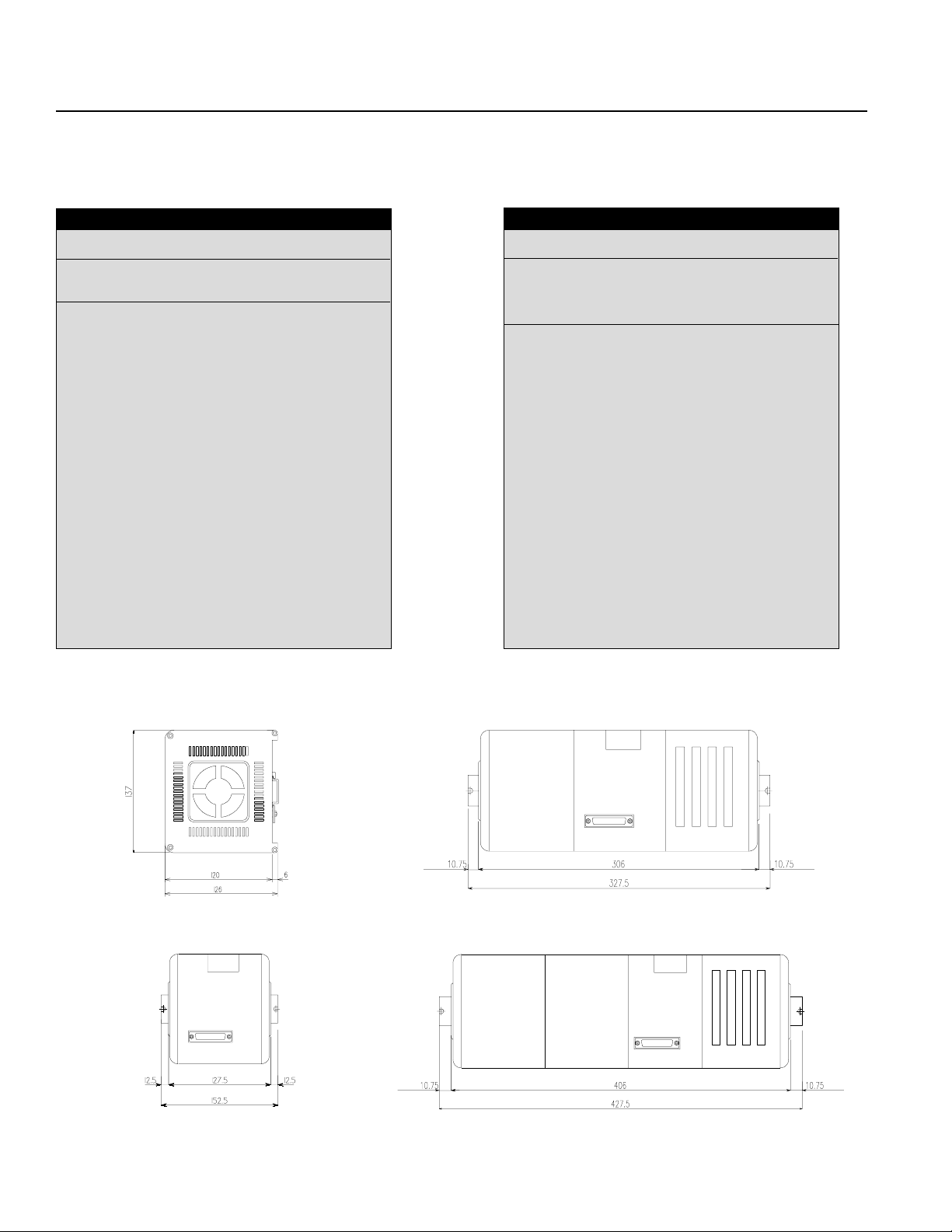
Chapter 1. Setting Up
[Unit Configuration Tables]
*Any output less than 100W is considered as 100W.
Table 1
2-axis (6 combinations) Configuration
100-100 A
200-200 B
200-100 B
400-400 C
400-200 C
400-100 C
Table 2
3-axis (10 combinations) Configuration
100-100-100 B
200-200-200 C
200-200-100 C
200-100-100 C
400-400-400 D
400-400-200 D
400-400-100 D
400-200-200 C
400-200-100 C
400-100-100 C
Dimension Drawings
(Side view)
Front view
A
B
C
Page 58
Page 64

Chapter 1. Setting Up
Table 3
4-axis (15 combinations) Configuration
100x4 B
200x4 C
200x3 + 100x1 C
200x2 + 100x2 C
200x1 + 100x3 C
400x4 E
400x3 + 200x1 E
400x3 + 100x1 E
400x2 + 200x2 D
400x2 + 200x1 + 100x1 D
400x2 + 100x2 D
400x1 + 200x3 D
400x1 + 200x2 + 100x1 D
400x1 + 200x1 + 100x2 D
400x1 + 100x3 C
E
D
Page 59
Page 65

Chapter 1. Setting Up
Table 4
5-axis (18 combinations) Configuration
100x5 F
200x5 G
200x4 + 100x1 G
200x3 + 100x2 G
200x3 + 100x3 F
200x1 + 100x4 F
400x3 + 200x2 H
400x3 + 200x1 +100X1 H
400x3 + 100x2 H
400x2 + 200x3 H
400x2 + 200x2 + 100x1 H
400x2 + 200x1 + 100x2 H
400x2 + 100x3 G
400x1 + 200X4 G
400x1 + 200x3 + 100x1 G
400x1 + 200x2 + 100x2 G
400x1 + 200x1 + 100x3 G
400x1 + 100x4 F
Table 5
6-axis (19 combinations) Configuration
100x6 F
200x6 G
200x5 + 100x1 G
200x4 + 100x2 G
200x3 + 100x3 G
200x2 + 100x4 F
200x1 + 100x5 F
400x3 + 100x3 H
400x2 + 200x4 H
400x2 + 200x3 + 100x1 H
400x2 + 200x2 + 100X2 H
400x2 + 200x1 + 100X3 H
400x2 + 100x4 G
400x1 + 200x5 H
400x1 + 200x4 + 100x1 H
400x1 + 200x3 + 100x2 H
400X1 + 200x2 + 100x3 G
400x1 + 200x1 + 100x4 G
400x1 + 100x5 G
Table 6 Table 7
7-axis (19 combinations) Configuration
100x7 F
200x7 H
200x6 + 100x1 H
200x5 + 100x2 H
200x4 + 100x3 G
200x3 + 100x4 G
200x2 + 100x5 G
200x1 + 100x6 G
400x3 + 100x4 H
400x2 + 200x2 + 100X3 H
400x2 + 200x1 + 100x4 H
400x2 + 100x5 H
400x1 + 200x6 H
400x1 + 200x5 + 100x1 H
400x1 + 200x4 + 100x2 H
400x1 + 200x3 + 100x3 H
400X1 + 200x2 + 100x4 G
400x1 + 200x1 + 100x5 G
400x1 + 100x6 G
8-axis (17 combinations) Configuration
100x8 F
200x8 H
200x7 + 100x1 H
200x6 + 100x2 H
200x5 + 100x3 H
200x4 + 100x4 G
200x3 + 100x5 G
200x2 + 100x6 G
200x1 + 100x7 G
400x2 + 200x2 + 100X4 H
400x2 + 200x1 + 100X5 H
400x2 + 100x6 H
400x1 + 200x4 + 100x3 H
400x1 + 200x3 + 100x4 H
400X1 + 200x2 + 100x5 H
400x1 + 200x1 + 100x6 H
400x1 + 100x7 G
Page 60
Page 66

Chapter 1. Setting Up
9. 12-slot Expansion Unit
A 12-slot expansion unit is available as an option and is used in the following situations.
(1) When the total number of inputs and outputs exceeds 96.
(2) When the total number of inputs and outputs is 96 and a flash memory card is used.
(3) When the total number of inputs and outputs is 96 and a 2-channel RS232 unit is used.
Please refer to pages 58 and 59 for the servo unit and CPU unit assembly configuration.
The drawing below gives the external dimensions for the 12-slot expansion unit.
Page 61
Page 67

Chapter 1. Setting Up
10. Bleeder Resistor
If the selected module uses a large amount of voltage, there will also be a large amount of regenerative voltage which in
some cases may require you to attach a bleeder resistor. The determination of whether to attach a bleeder resistor is made
for each servo unit separately and is dependent on the total wattage of all motors for that unit. However, if the servo unit
has a brake specification, there is a brake box (option) with a built-in discharge circuit.
Below, we illustrate the connection of a bleeder resistor to the controller using an M-SEL-G-3-AC-200-200-100 module as
an example.
Bleeder resistor connector (RB)
Servo unit 2 (100W 4-axis)
For 1 axis
Servo unit 1
(200W 2 axis)
For 2 axes
Bleeder resistor
connector (RB)
In the above module, servo unit 1 has a large combined motor capacity, which may require a discharge circuit so a bleeder
resistor is attached. In this case, the cable for connecting the resistor to the controller is plugged into the resistor connector
RB. Servo unit 2 does not require a resistor since the motor capacity is small. The resistor connector (RB) becomes a
reserve connector.
* At present, the general rule is that a bleeder resistor is attached for each servo unit in which the total motor capacity of
all the axes is 200W or greater for an AC motor and 300W or greater for a DC motor. Also, if you are using the actuator
as a vertical axis, the optional bleeder resistor is necessary even if you are not using a brake (box).
Note: If you forget to attach a bleeder resistor when the actuator is carrying a vertical load, excessive regenerative voltage
will cause an "A1" driver alarm. If this happens, turn the power OFF, then turn the power back ON to home the actuator.
Dimensions
M-SEL-G-3-AC-200·200·100
Page 62
Page 68

Chapter 1. Setting Up
Part 8 Super SEL Controller Maintenance
To ensure safe and trouble-free operation of your Super SEL system, a regular maintenance and inspection program should be
implemented. Be sure to turn OFF the power before initiating any maintenance or inspection work. An inspection is recommended at least once every 6 to 12 months. However, depending on the environment, a more frequent inspection schedule may
be advisable.
(1) Inspection Guidelines
• Check and make sure that the power supply to your Super SEL Controller is maintained at 90 ~ 127V.
• Check the controller vents and clean any accumulated dirt or dust.
• Check the controller cable (controller → axis) and make sure there are no loose screws or disconnections.
• Check for loose controller mounting screws. Tighten if necessary.
• Check each cable (axis cables, general I/O cables, system I/O cables, power supply cable). Check for loose connections,
damage, or excessive wear. Replace if necessary.
(2) Recommended Spare Parts
It is advisable to keep a small supply of spare parts. In critical applications, it may be advisable to keep an entire spare
Super SEL Controller on hand. The following spare parts are recommended:
• Cables
• Batteries* (Ni-Cd batteries have a general shelf life of about 6 years but this varies depending on use conditions and
environment )
(3) Memory Backup
When the controller is fully charged, backup memory is guaranteed for 3 months. In actuality, the backup memory is not
erased for 6-8 months but if the controller is to be left for a long period (more than 3 months) without having current run
through it, please take precautions to save your program, position data, and parameters. To fully charge the controller if it
does not contain any data, you will need to leave the controller with the power ON for 3 days.
If the memory is erased, the system's preset parameters will be set but the actuator will not run properly in this condition.
Page 63
Page 69

Chapter 2. Operation
Part 1 Basics in Operating Your Super SEL Controller
1. Summary of Teaching Pendant Operation
The tree structure below illustrates the teaching pendant mode structure.
Mdi
Value Input
Posi
Position Teaching
Power ON
ROM Version Display
Prog
Program Mode
Play
Play Mode
Parm
Parameter Mode
Test
Test Mode
Teac
JOG Direct
Aprg
Application Program
Step
Etc.
The basics of Teaching Pendant operation of your Super SEL Controller will display the above messages on the LCD
display screen. Press F1 ~ F4 to move through the branch modes and press ESC to go back to the main branch.
Page 64
Page 70

Chapter 2. Operation
2. Teaching Pendant Key Functions
Teaching pendant key functions are as follows:
01 Cursor: Numbers can be changed when the cursor is positioned underneath.
"Inc" Increment: This key increases the step number or point number.
"Dec" Decrement: This key decreases the step number or point number.
"Esc" Escape: This key is used to go back to the previous display.
" . " Decimal Point Key: When creating an application program, the display will go to the next command
menu.
"-" Minus Key: When creating an application program, the display will return to the previous
command menu.
" = < " Data Key, JOG Key: Dual function key for use in data input and axis Jog functions.
↵ ↵
"
↵ " Return Key: This key registers the value at the cursor, and makes it effective.
↵ ↵
Note: If the main power is turned OFF, all programs and data will be stored for a guaranteed period of 3 months.
Page 65
Page 71

Chapter 2. Operation
Part 2 Teaching Pendant Operation
1. Mode Selection
(LCD Screen Display) (Operation)
IA. Super. SEL
Teach 01/13/95
Start (Blinking)
F1 F2 F3 F4
1. Initial Display
Press F1 (Start) (To P66. 2)
IA. Super SEL
Teach 01/13/95
Main V2.50 07/14/95
Start (Blinking)
F1 F2 F3 F4
Mode Select
Prog Play Parm Test
F1 F2 F3 F4
2. Controller ROM Version Display
Press F1 (Start) (To P66. 3)
3. Mode Selection Display
F1- Prog (Program) Mode (P67. 4)
F2- Play (Play/Execution) Mode (P81. 22)
F3- Parm (Parameter) Mode (P75. 18)
F4- Test (Test) Mode (P79. 21)
*Note* In case of an input error, press the ESC key to return
to the previous screen and then resume operation.
For any operation, if you continue pressing the ESC
key, you will eventually return to this initial display.
Page 66
Page 72

Chapter 2. Operation
2. Program Mode
(LCD Screen Display) (Operation)
Prog
Posi Aprg
F1 F2 F3 F4
Creating position data
4. Program Mode (Press F1 at Step 3)
F1- (Posi: Position) Position Data Input (P67. 5)
F2- (Aprg: Application Program) Super SEL Program-
ming Edit Display (P72. 15)
Esc- Return to Mode Selection Display (P66.3)
Posi
Mdi Teac Step Etc
F1 F2 F3 F4
Point data for Axis 1
Point data for Axis 2
Mdi - 1 No 1 [1] - 8
1.234 12.345
123.456 1234.567
Inc Dec Clr Del
F1 F2 F3 F4
Mdi - 1 No 1 [1] - 8
Cursor Position Axis Name
Axis # No. of axes connected
5. Position (Position Data) Input Display (Step 4. Press F1)
F1- Mdi Mode (Position Data Direct Input) (P67. 6)
F2- Teac (Position Data Teaching) Mode (P70. 12)
F3- Point Step (Position Data Step) Mode (P69. 10)
F4- Return to Etc Edit Display 2 (P68. 6-2)
Esc- Return to Program Mode (P67. 4)
6. Mdi Mode
6-1 Position Number Input Mode (Step 5. Press F1)
Input 4-digit numbers.
F1- (Inc: Increment) Increments the position number
displayed by 1.
F2- (Dec: Decrement) Decrements the position number
displayed by 1.
F3- (Clr: Clear) Clears all data (return to 0) for reentry.
F4- (Del: Delete) Deletes input data
Return - Position Data Input (P68. 7)
Esc- Returns to Position Data Input Display (P67. 5)
*This screen can only display up to a maximum of four axes.
Page 67
Page 73
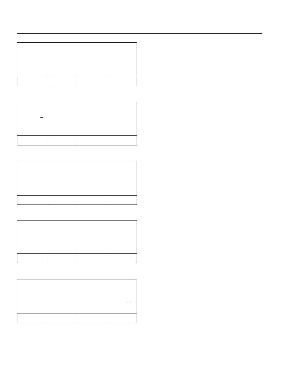
Chapter 2. Operation
Posi
Shift Copy Clr Etc
F1 F2 F3 F4
Mdi - 1 No 1 [1] - 8
1.23
4 12.345
123.456 1234.567
Wrt Can Clr Etc
F1 F2 F3 F4
Mdi - 1 No 1[1] - 8
1.23
4 12.345
123.456 1234.567
Axis+ Axis- Vel Etc
F1 F2 F3 F4
6-2 Position (Position Data) Input Display 2 (Go back to the
display in Step 5. Press F4)
F1- (Shift) Position Shift Mode (P69. 11-1)
F2- (Copy) Position Data Copy (P69. 11-1)
F3- (Clr: Clear) Position Data Clear (Deletion) (P69.
11-2)
F4- Position (Position Data) Input Display (P67. 5)
Esc- Return to Program Mode (P67. 4)
7. Position Data Input Mode (Step 6-1, Return Key)
Direct input (5-digit integers before decimal point and 3
digits after the decimal point.)
F1- (Wrt: Write) Saving position data
F2- (Can: Cancel) displays xxxx.xxx.
F3- (Clr: Clear) displays 0.000 for data reentry.
F4- Position data input sub menu. (P68. 8)
8. Position Data Input Sub Menu (Step 7. F4)
Direct Input (5-digit integers before decimal point and 3digits after the decimal point)
F1- (Axis+) Increments axis number by 1. (P68. 8-1)
F2- (Axis-) Decrement axis number by 1. (P68. 8-2)
F3- (Vel: Velocity) Set velocity and acceleration for
the position number. (P69. 9)
F4- (Etc) Returns to Position Data Input Mode (P68. 7)
Mdi - 1 No 2[2] - 8
1.234 12.34
5
123.456 1234.567
Axis+ Axis- Vel Etc
F1 F2 F3 F4
Mdi - 1 No 8[8] - 8
2345.678 1.234
12.345 1234.5
Axis+ Axis- Vel Etc
F1 F2 F3 F4
8-1 Increments axis number by 1. (Step 8, F1)
8-2. Decrements axis number by 1. (Step 8, F2)
6
Page 68
Page 74
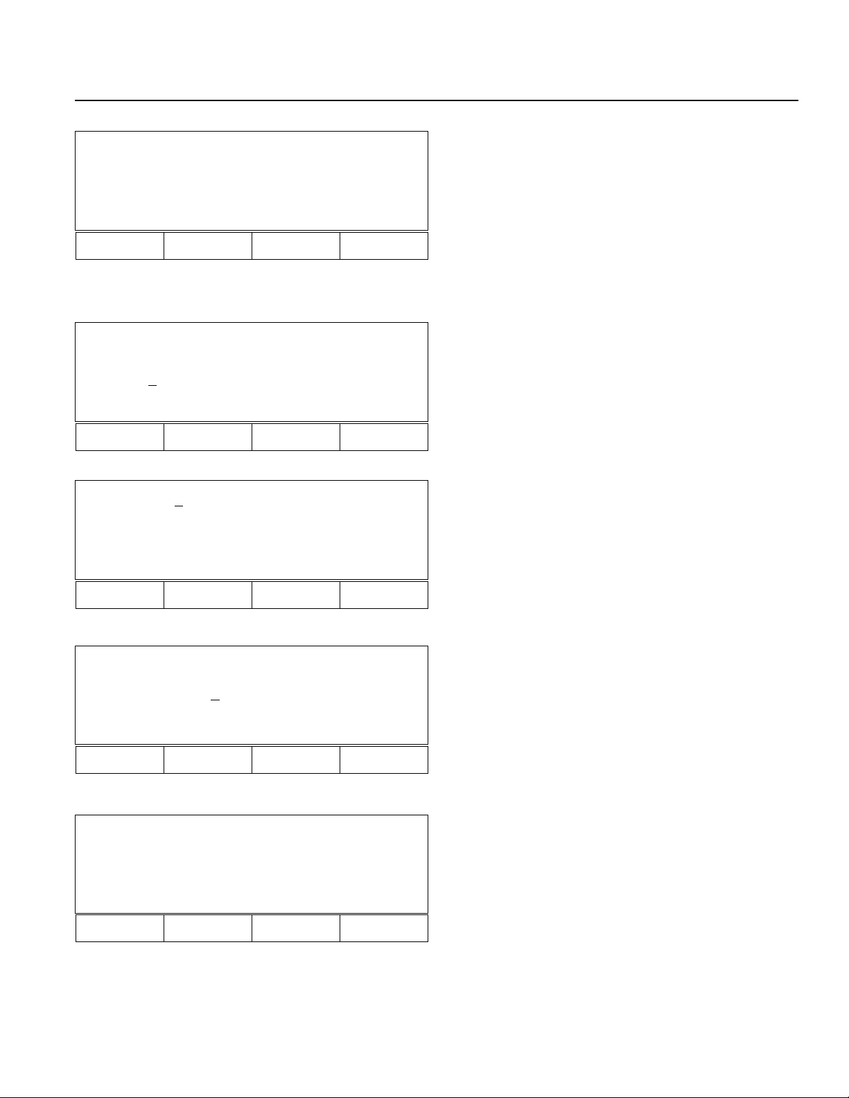
Chapter 2. Operation
Mdi - 1 No 8[8] - 8
500.000 600.000
700.000 600.000
Wrt Can Clr Etc
F1 F2 F3 F4
8-3 Use the F1 key (Wrt) to save data for up to 8 axes.
However, do not write data while a program is running
(cannot guarantee data will be saved).
F1- Wrt: Write
F2 - Can: Cancel
F3- Clr: Clear
Mdi - 1 No. 1[1] - 8
1.234 12.345
Vel [30
0] Acc[0.99]
Wrt Axis Clr
F1 F2 F3 F4
Step - 1 No 1[1] - 8
1.234 12.345
123.456 1234.567
Inc Dec Go JVel
F1 F2 F3 F4
Posi Shift
From St.
1 Ed.
To St. Ed.
Clr
F1 F2 F3 F4
9. Position Data Velocity and Acceleration Setting (Step 8.
F3)
(Velocity: 3-digits, Acceleration 9.99, 2-digits after decimal point.)
10. Point Step Mode (Go back to the display in step number 5,
then press F3.)
F1- Position No. +1
F2- Position No. -1
F3- Move to designated position
F4- Designate velocity
11-1 Position Shift (Move) Mode (6-2. F1 key)
Moves the specified multiple position data. Input the
beginning and the ending position No. of the original
position (From), then input the beginning and the ending position No. of the target position (To).
*Position Copy Mode (6-2. F2 key) for duplication can
be operated in the same manner.
Clear All Position
Clr
F1 F2 F3 F4
11-2 Position Clear Mode (Go back to the display in Step
6-2. Then, press F3.)
F3- Clears all position numbers.
F1- Execute
Page 69
Page 75
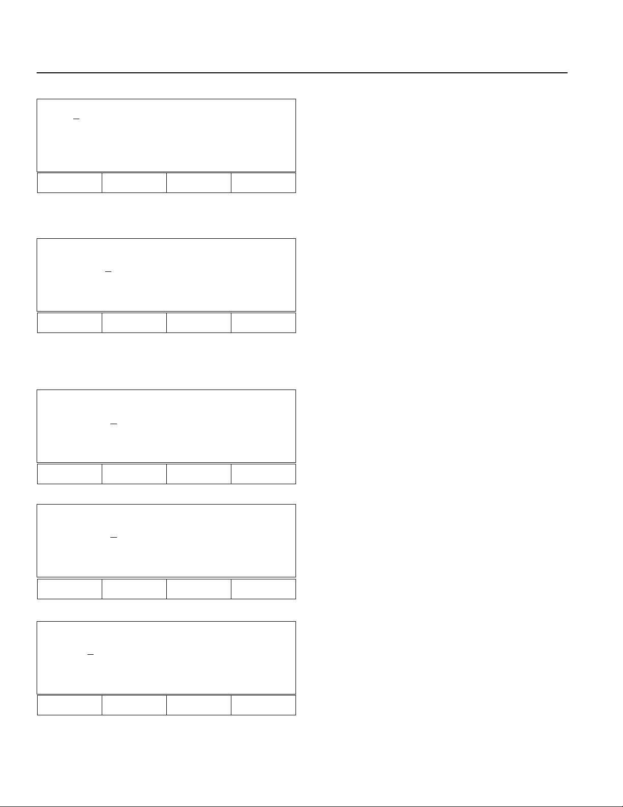
Chapter 2. Operation
Teac- 1 No 1[1] - 8
1.234 12.345
123.456 1234.567
Inc Dec Go JVel
F1 F2 F3 F4
Teac- 1 No 1[1] - 8
1.23
123.456 1234.567
JVel Jog SvOf Etc
F1 F2 F3 F4
4 12.345
12. Teaching Mode (Go back to the display in Step 5, then
press F2.
Position Number Input Mode (2-digit number input)
F1- Increments position number by 1.
F2- Decrements position number by 1.
F3- Moves actuators from current position to the
position designated in the display.
F4- Sets velocity.
Return- Performs teaching for each axis. (P70. 13)
13. Teaching Selection Mode (12. Return Key)
Select Jog or SvOf (Servo OFF, Manual)
The cursor is located under axis number 1. Press Etc to
switch to another axis.
F1- Select jog velocity.
F2- Set for jog movement. (P70. 13-1)
F3- Set for manual (direct) teaching. (P71. 14)
F4-
Velocity setting and axis changing mode. (P70. 13-3)
Jog- 1 No 1[1] - 8
1111.12
3 12.345
123.456 1234.567
Wrt JVel SvOf Etc
F1 F2 F3 F4
Jog- 1 No 1[1] - 8
1111.12
3 12.345
123.456 1234.567
Axis + Axis - Vel Etc
F1 F2 F3 F4
Teac- 1 No 1[1] - 8
1.23
4 12.345
123.456 1234.567
Axis+ Axis
-
Vel Etc
13-1 Jog Mode (Step 13. F2)
Turns all servos ON and also indicates the present
position.
When Wrt is selected, the present position will be
saved.
F4- Velocity setting and axis selection mode (P70. 13-2)
13-2 Jog Mode (Step 13-1, F4)
Velocity, axis selection.
When selecting Axes to jog:
F1- Axis+ moves cursor forward 1 axis.
F2- Axis- moves cursor backward 1 axis.
13-3 Teaching Velocity Set, Axis Change Mode (Step 13. F4)
F1- Teach axis number + 1.
F2- Teach axis number - 1.
F3- Set velocity and acceleration for point data.
F4- Return to the display before selection.
F1 F2 F3 F4
Page 70
Page 76

Chapter 2. Operation
SvOf - 1 No 1[1] - 8
1111.12
3 12.345
123.456 1234.567
Wrt JVel Jog Etc
F1 F2 F3 F4
SvOf - 1 No 1[1] - 8
1111.12
3 12.345
123.456 1234.567
Axis
+
Axis
F1 F2 F3 F4
-
Vel Etc
SvOf - 1 No 1[1] - 8
1111.123 12.345
Vel[ 3
0] Acc[0.30]
Wrt Axis Clr
F1 F2 F3 F4
14. SvOf (Servo OFF, Manual • Direct Teaching) Mode (Go
back to the display in Step 13, then press F3)
Servo OFF for all connected axes.
Moves axis position manually (direct teaching).
Wrt: Saves data.
Return: Changes axis number.
14-1 SvOF Mode (Step 14. F4)
Velocity Setting, Axis No. Selection
Use to set point position velocity or to change axis
number.
F3- àVelocity Setting Selection Display (P71. 14-2)
14-2 SvOf Mode (Step 14-1. F3)
Velocity Setting Selection
Input velocity and accerelation, then press Return key.
F2- Return to SvOf Mode (P71. 14)
F3- Clr (Clear) clears input value, for re-entry.
Page 71
Page 77
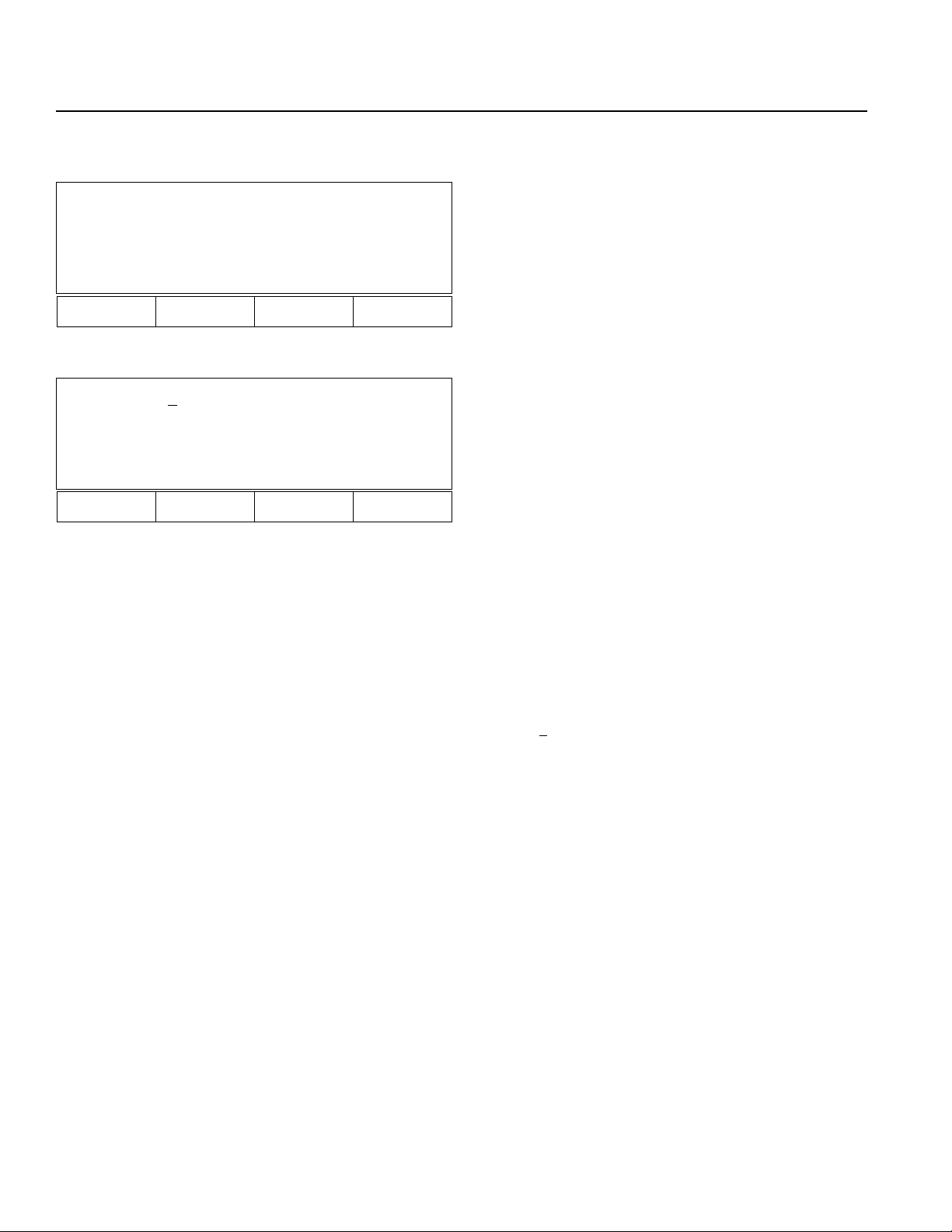
Chapter 2. Operation
Application Programming
Aprg
Edit Copy
F1 F2 F3 F4
Edit 1- 1 [ 50]
MOVP 1
699 A N499
Inc Dec Clr Del
F1 F2 F3 F4
15. Super SEL Programming Edit Display (Go back to the
display in Step 4, then press F2)
F1- (Edit Mode) Perform SEL programming, editing,
addition, insertion, and deletion. (P72. 16)
F2- (Copy Mode) Copies or overwrites programs.
(P74. 17)
16. Super SEL Programming Edit Mode (15. F1)
16-1 Program Number Input Mode
F1- Increments program number by 1.
F2- Decrements program number by 1.
F3- Clears input value for re-entry.
F4- Deletes program number.
Return- Switches to step number input mode when the
program number input is within the appropriate range. (P73. 16-2)
When a program number exists, step number 1 will be
displayed. When a program number does not exist, a
space will be displayed.
Page 72
( Edit 1- 1 [ 50] )
| | |
Prog. No. Step No. Step Number
( MOVP 1 )
| |
Command Operation 1
( 699 A N499)
| | |
Operation 2 Result Continuous Condition
Page 78
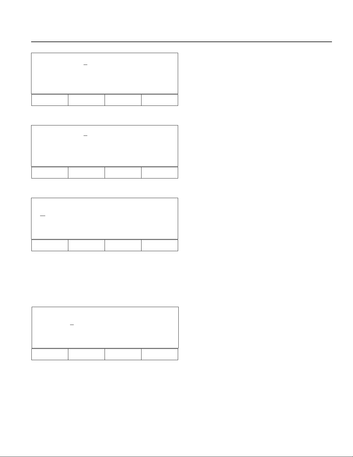
Chapter 2. Operation
Edit 1- 1 [ 50]
MOVP 1
699 A N499
Inc Dec Clr etc
F1 F2 F3 F4
16-2 Step Number Input Mode (Step 16-1. Return Key)
F1- (Inc) Increments step number by 1.
F2- (Dec) Decrements step number by 1.
F3- (Clr) Clears data for re-entry.
F4- Additional mode (Insertion mode, deletion mode,
etc.) (P73. 16-2-1)
Edit 1- 1 [ 50]
MOVP 1
699 A N499
Ins Del etc
F1 F2 F3 F4
Edit 1- 1 [ 50]
MOVP 1
699 A N499
ABPG ACC ADD AND
F1 F2 F3 F4
16-2-1 Step Number Input Mode 1 (Step 16-2. F4)
F1- (Insertion) Add steps.
F2- (Delete) Delete steps.
16-3 Edit Command Input Mode (Step 16-2. Return Key)
4 commands will be displayed from F1 to F4.
Pressing the decimal point (.) will display the commands in alphabetical order.
Pressing the minus sign (-) will display the commands
in reverse alphabetical order.
Select a command by pressing F1 ~ F4, . (decimal
point), or - (minus) sign.
Press CR (Return key) to display Operation 1 Input
Mode (P73. 16.4).
Edit 1- 1 [ 50]
MOVP
1
699 A N499
* BS Clr
F1 F2 F3 F4
16-4 Operation 1 Input Mode (Step 16-3. Return key)
Input operation 1 of the selected command.
F1- (*) Designate variables indirectly.
F2- (BS: Back Space) Clears last input value. Cursor
will move backwards.
F3- (Clr: Clear) Clears all the values input for new
data entry.
Return- Input values will be saved, then operation 2
input mode will be displayed. (P74. 16-5)
ESC- Command input mode
Page 73
Page 79
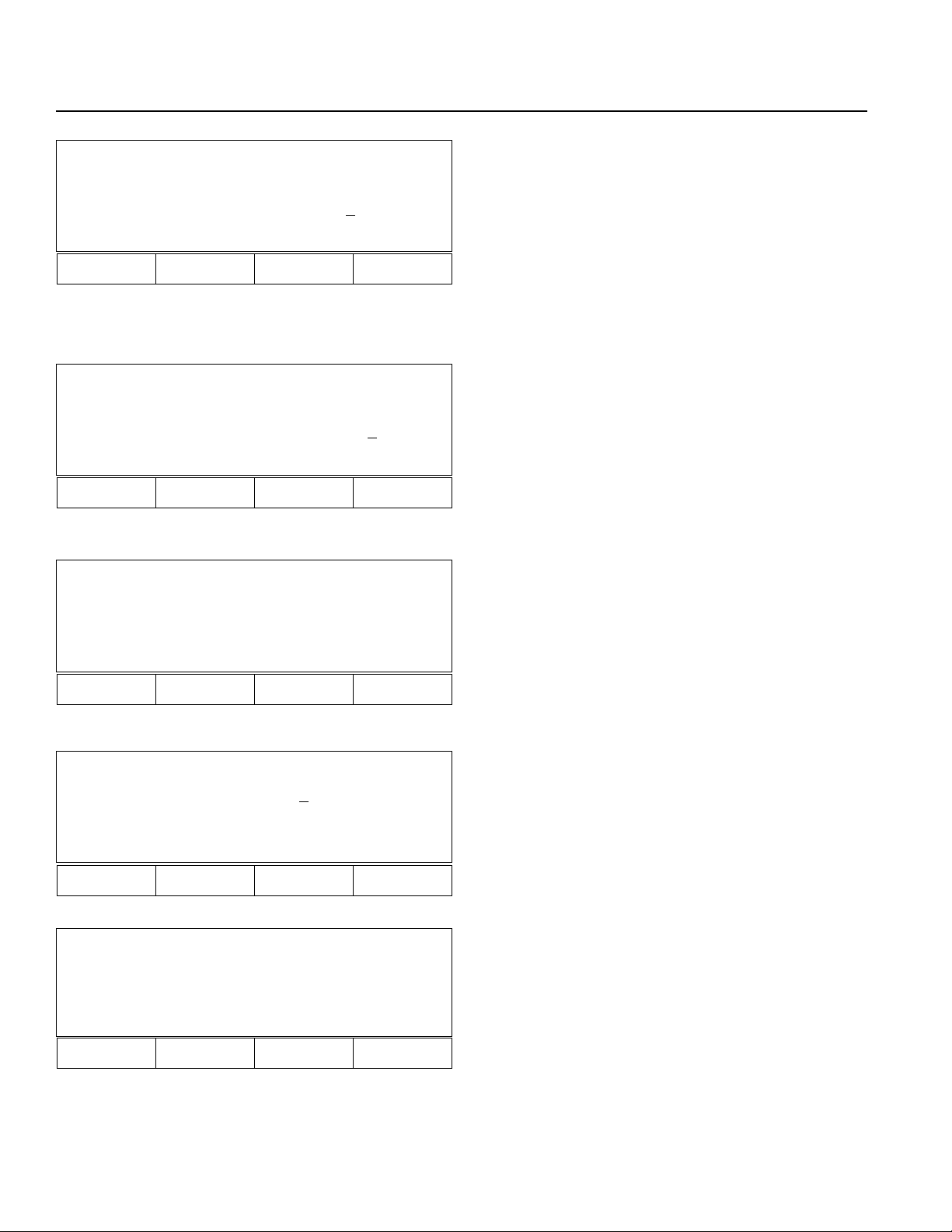
Chapter 2. Operation
Edit 1- 1 [ 50]
MOVP 1
699 A N499
BS Clr
F1 F2 F3 F4
Edit 1- 1 [ 50]
MOVP 1
699 A N
499
And Or Clr Not
F1 F2 F3 F4
Edit 1- 1 [ 50]
MOVP 1
699 A N499
Clr Wrt
16-5 Operation 2 Input Mode (Step 16-4, Return key)
Same as 16-4
16-6 Result Input Mode (16-4. Return key)
Input result, output and flag.
F2- Clears the last entry and moves cursor backwards
using BS (back space).
F3- Clears all data.
Return- Continuous Condition Input Mode (P74. 16-7)
16-7 Continuous Condition Input Mode (Step 16-6, Return
key)
F1- Select And
F2- Select Or
F3- Clears data entry
F4- Select Not
Return- Confirmation Mode (P74. 16-8)
16-8 Confirmation Mode (Step 16-7. Return key)
F3- Re-input from command
F4- Proceeds to the next step number after saving
(Wrt) the current step number. ( In the case of insertion, the step number remains the same).
F1 F2 F3 F4
Prog Copy
From
1
To
Clr
F1 F2 F3 F4
Prog Copy
From 1 [ 50]
To 1 [ 50]
Copy OWrt
F1 F2 F3 F4
17. Copy Mode (Go back to the display in Step No. 15, then
press F2.)
17-1 Copies program. (Step 15. F2)
Input program number to be copied after "From", then
input a new program number after "To".
F3- Clears data for data entry.
Return- Copy, Overwrite Selection Mode (P74. 17-2)
17-2 Copy, Overwrite Selection Mode (17-1. CR: return key)
F1- Copies the program.
F2- Overwrites the program.
Page 74
Page 80

Chapter 2. Operation
3. Parameter Mode
*Important* Please contact our technical service department if parameters need to be changed for your system.
Para
Axis Sys
F1 F2 F3 F4
Para Axis
Srvo Home Motr Name
F1 F2 F3 F4
Para System
Prog Pos Srvo Etc
18. Parameter Mode (Step 3, F3)
F1- Parameter mode for each axis (P75. 18-1)
F2- System parameter mode (P75. 18-2) (P77.20)
18-1 Parameter Mode for each axis (Step 18. F1)
F1- Servo parameter mode for each axis (P75.19-1)
F2- Home parameter mode for each axis (P76.19-2),
axis activation mode
F3- Motor parameter mode for each axis (P76. 19-3)
F4- Axis name parameter mode for each axis (P77. 19-4)
18-2 System Parameter Mode (Step 18. F2)
F1- System program parameter mode
F2- System point parameter mode
F3- System servo parameter mode
F4- Additional selection mode (P75. 18-3)
F1 F2 F3 F4
Para System
Sio Cir Etc
F1 F2 F3 F4
Para Axis 1[1] Srvo
1. Numerator
Inc [ < = ]
Axis
+
Dec Clr Wrt
F1 F2 F3 F4
1
18-3 System parameter additional selections (Step 18-2. F4)
F1- (Sio: Serial I/O RS232C) System Sio parameter
mode (P78. 20-4)
F2- (Cir: Circle) System path/circular parameter mode
(P78. 20-5)
F4- (Etc) Returns to system parameter mode. (P75. 18-
2)
19-1 Servo Parameter Mode (18-1. F1)
F1- Goes to next axis no. (+1). Axis name will also be
changed. (P76. 19-1-1)
F2- Goes backward -1 (P76. 19-1-2)
F3- Clears data for data entry
F4- Direct number input
Return- (Inc[<=]) adds +1
Page 75
Page 81

Chapter 2. Operation
Para Axis 2[2] Srvo
1. Numerator
Inc [<=]
Axis+ Dec Clr Wrt
F1 F2 F3 F4
1
19-1-1 Press F1 to display axis number +1.
Para Axis 1[1] Srvo
9. Soft Limit (-)
Inc [<=]
0
Axis+ Dec Clr Wrt
F1 F2 F3 F4
Para Axis 1[1] Home
1. Home Dir
Inc[<=]
1
Axis+ Dec Clr Wrt
F1 F2 F3 F4
Para Axis 1[1] Home
3. Home Sequence
Inc[<=]
1
Axis+ Dec Clr Wrt
F1 F2 F3 F4
19-1-2 Press F2 to display item -1.
19-2 Home parameter mode for each axis, axis activation
mode (Step 18-1, F2)
19-2-1 Home parameter mode for each axis, axis activation
mode (Step 19-2, Press the RETURN key twice). Doing this brings you to the 3. Home Sequence screen.
By inputting 0 here, the axis will be inactivated. Homing or Jog will not be performed. (Position indicator
will display ∆).
By inputting a number (1 ~ 9), homing order for all
activated axes can be designated.
Para Axis 1[1] Motr
1. Motor RPM Max
Inc[<=] 400
0
Axis+ Dec Clr Wrt
F1 F2 F3 F4
19-3 Motor Parameter Mode (Step 18-1. F3)
Page 76
Page 82
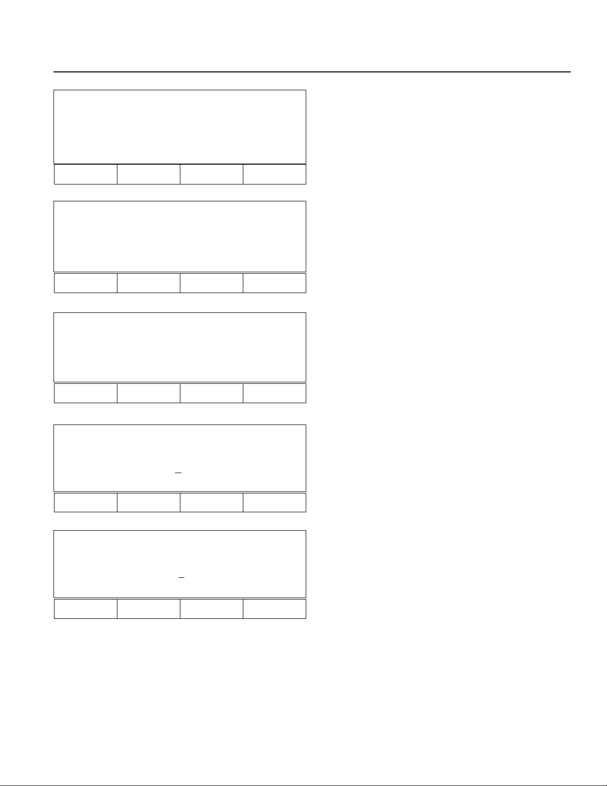
Chapter 2. Operation
Para Axis 1[1] Name
Axis+ Axis - Name+ Name-
F1 F2 F3 F4
Para Axis 1[2] Name
Wrt Name+ Name-
F1 F2 F3 F4
19-4 Parameter Name Mode for Each Axis (Step 18-1. F4 Key)
F1- Increments axis number by 1
F2- Decrements axis number by 1
F3- Increments axis name by 1 for range 1 ~ 9, A ~ Z
(P77. 19-4-1)
F4- Decrements axis name by 1 for range 1 ~ 9, A ~ Z
19-4-1 Axis Name Change (Step 19-4. F3)
F1- (Wrt) Change axis name.
Para System
Prog Pos Srvo Etc
F1 F2 F3 F4
Para System Prog
1.Auto Start PRG
Inc[<=]
0
Inc Dec Clr Wrt
F1 F2 F3 F4
Para System Pos
1.Point Size
Inc[<=] 10 0
0
Inc Dec Clr Wrt
20. System Parameter Mode (Step 18. F2)
F1- System Program Parameter Mode (P77. 20-1)
F2- System Point Parameter Mode (P77. 20-2)
F3- System Servo Parameter Mode (P78. 20-3)
20-1 System Program Parameter Mode (Step 20. F1)
Press the RETURN key to increment the item. (Inc[<=])
20-2 System Point Parameter Mode (Step 20. F2)
F1 F2 F3 F4
Page 77
Page 83

Chapter 2. Operation
Para System Srvo
1. Axis Size
Inc [<=]
8
Inc Dec Clr Wrt
F1 F2 F3 F4
Para System Sio
1. Terminal ID
Inc[<=] 9
9
Inc Dec Clr Wrt
F1 F2 F3 F4
Para System Cir
1. Circle Angle
Inc[<=] 15.
9
Inc Dec Clr Wrt
20-3 System Servo Parameter Mode (Step 20. F3)
20-4 System Sio Parameter Mode (18-3. F1 Key)
20-5 System Circle, Arc, Parameter Mode (Step 18-3. F2)
F1 F2 F3 F4
Page 78
Page 84

Chapter 2. Operation
4. Test Mode
Test
Flag In Out Ver
F1 F2 F3 F4
21. Test Mode (3. F4 Key)
F1- (Flag) Flag displayed. Press F1 and "1" key
simultaneously. RamCL (Ram Clear) Mode will
appear on the display.
F2- (In) Input Port Display (P79. 21-2)
F3- (Out) Output Port (P79. 21-3)
F4- (Ver: Version) Displays current software version of
Servo, Main and Teaching Pendant (P80. 21-4)
Test
RamCL In Out Ver
F1 F2 F3 F4
Test 0123456789 (In)
000-> 1000000001 <-009
010-> 0000001100 <-019
Inc Dec
F1 F2 F3 F4
Test 0123456789 (Out)
300->
0000000000<-309
310->0000001100<-319
Inc Dec Clr 0/1
F1 F2 F3 F4
Test 0123456789 (Out)
310->
0000000000<-319
320->0000001100<-329
Inc Dec Clr
21-1 While holding down both the F1 and "1" keys, the
display will remain the same as shown on the left.
When the keys are released, Memory Clear Mode
(RamCL) will appear. (P80. 21-5)
21-2 Test Input Port Display (Step 21. F2)
Displays input port status.
F1- Port displayed. +10
F2- Port displayed. -10
21-3 Test Output Port Display (21. F3)
F1- Output port +10 (P79. 21-3-1)
F2- Output port -10
F3- All displayed ports will be 0 output
F4- Output 0 ⇒1, 1⇒0
. (decimal point), RETURN key moves cursor to the right
- (minus key) moves cursor to the left
"0" outputs cursor position port to 0
"1" outputs cursor position port to 1
With this display, you can force output ports ON/OFF,
but you cannot monitor outputs as they change on the
controller side in real time.
21-3-1 F1 (output port +10)
F1 F2 F3 F4
Page 79
Page 85

Chapter 2. Operation
Test Version 1[1]
MotorV1.00 12/13/93
Main V1.00 1/25/94
Axis+ Axis- Main Teac
F1 F2 F3 F4
RamCL
All Para Prog Pos
F1 F2 F3 F4
21-4 Test Version Mode (Step 21. F4)
21-5 Memory Clear (RamCL) Mode (Step 21. F1 + 1 key)
Caution: This will erase all data. Make sure to backup
all data before doing this operation.
F1- Clears system parameter, program, and position
area (P80. 21-5-1)
F2- Clears system parameter (P80. 21-5-2)
F3- Clears application program area (P80. 21-5-3)
F4- Clears position data area (P81. 21-5-4)
RamCL All
CLROk?
F1 F2 F3 F4
RamCL Para
CLROk?
F1 F2 F3 F4
RamCL Prog
21-5-1 F1(All) is selected.
Press F1 (CLROk?: Clear OK?)
Note: This is the same as RESET.
21-5-2 F2 (Para) is selected.
Press F1 (CLROk?) - same as Reset
Note: This is the same as RESET.
21-5-3 F3 (Prog) is selected.
Press F1
Clears all application programs.
CLROk?
F1 F2 F3 F4
Page 80
Page 86

Chapter 2. Operation
RamCL Pos
CLROk?
F1 F2 F3 F4
5. Play Mode
Play 1-1 [ 50]
MOVP 1
699 A N499
Inc Dec Clr
F1 F2 F3 F4
21-5-4 F4 (Pos) is selected.
Press F1
Clears all position data.
22. Play (Play) Mode (3, F2 Key)
22-1 Play Program Input Mode
Input program number to execute (or stop). Program
status can be seen by pressing START then PROG.
Play 1-1 [ 50]
MOVP 1
699 A N499
Show Go Stat HLT
F1 F2 F3 F4
Play 1-1 [ 50]
MOVP 1
699 A N499
Posi Play Stat Etc
F1 F2 F3 F4
Play 1- No 1 [1]-2
1111.123 2222.234
3333.345 4444.456
Axis+ Axis- Stat
F1 F2 F3 F4
22-2 Program Execution/Stop Selection (22-1. CR: return key)
F1- (Show) Monitoring (when the designated
program is executing.) (P84. 23)
F2- (Go) Program execution (P81. 22-3)
F3- (Status) show status (after checking the status,
select execution or stop)
F4- (HLT) Stop (P81. 22-3)
22-3 Execution Status Selection (22-2. F2) (22-2. F4)
F1- Axis status display (P81. 22-4)
F2- Other program execution, or stops currently
executing program. (P82. 22-5)
F3- Shows program status (P82. 22-6)
F4- Input port, Output port, Flags (P82. 22-7)
22-4 Axis Status Display Mode (22-3. F1)
F1- Checks other axis status (+)
F2- Checks other axis status (-)
( Play 1- No 1 [2]-8)
á
Starting axis
Page 81
Page 87

Chapter 2. Operation
Play 1-1 [ 50]
MOVP 1
699 A N499
Inc Dec Clr
F1 F2 F3 F4
Play 1 [Run 1- 0]
Prog
F1 F2 F3 F4
Play 1- 1 [ 50]
MOVP 1
699 A N499
In Out Flag Etc
22-5 Execution, Stop Mode (22-3, F2)
Input program number to be executed or stopped.
Returns to 22-3.
22-6 System movement and program number display (22-3,
F3)
22-7 I/O port, Flag Status Selection Mode (22-3. F4)
F1- Input port change display, select (P82. 22-8)
F2- Ouput port change display, select (P82. 22-9)
F3- Flag change display, select (P83. 22-10)
F4- Execute, status selection screen (P83. 22-12)
F1 F2 F3 F4
Play 0123456789 (In)
000 ->1000000001 <-009
010->1000001100<-019
Inc Dec
F1 F2 F3 F4
Play 0123456789 (Out)
300 ->1000000001 <-309
310->0000001100<--319
Inc Dec
F1 F2 F3 F4
22-8 Play Input Port Display (22-7. F1)
F1- Input Port +10
F2- Input Port -10
22-9 Play Output Display (22-7. F2)
F1- Output +10
F2- Output -10
Page 82
Page 88

Chapter 2. Operation
Play 0123456789 (Flg)
600->1000000001<-609
610->0000001100<-619
Inc Dec
F1 F2 F3 F4
22-10 Play Flag Display (22-7. F3)
F1- Flag +10
F2- Flag -10
Play 1-1 [50]
MOVP
699A N499
Posi Play Stat Etc
F1 F2 F3 F4
Play 1-1 [50]
MOVP 1
699A N499
In Out Flag Etc
F1 F2 F3 F4
Play [Run 1- 3]
1-2 2-2 3-2
Stop Etc
22-11-1 Select F1 (Show), F2 (GO), or F4 (HL T) from Program
Execution/Stop Selection Display (P81. 22-2) to stop
Play Mode (program stops). Execution Status Selection Display appears. Then press F4 (Etc). (P83. 2211-2)
22-11-2 I/O Port, Flag Status Selection Mode (P82. 22-7)
Press F4 (Etc). (P83. 22-12)
22-12. Execute, Status Selection Screen (22-7. F4)
F1 - Goes to Program Stop Selection Mode.
(P83. 22-13)
F1 F2 F3 F4
Play [Run 1-3]
1-2 2-2 3-2
Inc Dec StpAL Stp1
F1 F2 F3 F4
22-13 Program Stop Selection Mode (22-12. F1)
F1- Changes program number to be stopped.
F2- Changes program number to be stopped.
F3- Stops all the programs being executed.
F4- Stops program number with the cursor underneath.
Page 83
Page 89

Chapter 2. Operation
6. Show Mode
Play 3 -0 [ 6 ]
Posi Play Stat Etc
F1 F2 F3 F4
Play 3 No. 1 [1] -2
xxx.xx xxx.xx
Axis+ Axis- Stat
F1 F2 F3 F4
Play 3 No. 1 [1] -2
Home [ON] Servo [OFF]
Move [ON] xxx.xx
Axis+ Axis- Pos
F1 F2 F3 F4
23. Show Mode (Step 22-2. F1)
F1- Displays the position of each axis currently
moving (P84. 23-1-1)
F2- Execute other program (P85.23-2)
F3- Shows program status (P85. 23-3-1)
F4- Current Input/Output Status, Flag Status Mode
(P86. 23-4)
23-1-1 Position Display Mode (Step 23. F1)
F1- Checks other axis status (+)
F2- Checks other axis status (-)
F3- Shows program status (P84. 23-1-2)
23-1-2 Status Display Mode (Step 23-1-1. F3)
Display homing incomplete (OFF)/complete (ON),
servo ON/ OFF, moving incomplete (OFF)/complete
(ON), and current value.
F3- Return to Position Display Mode (P84. 23-1-1)
Page 84
Page 90
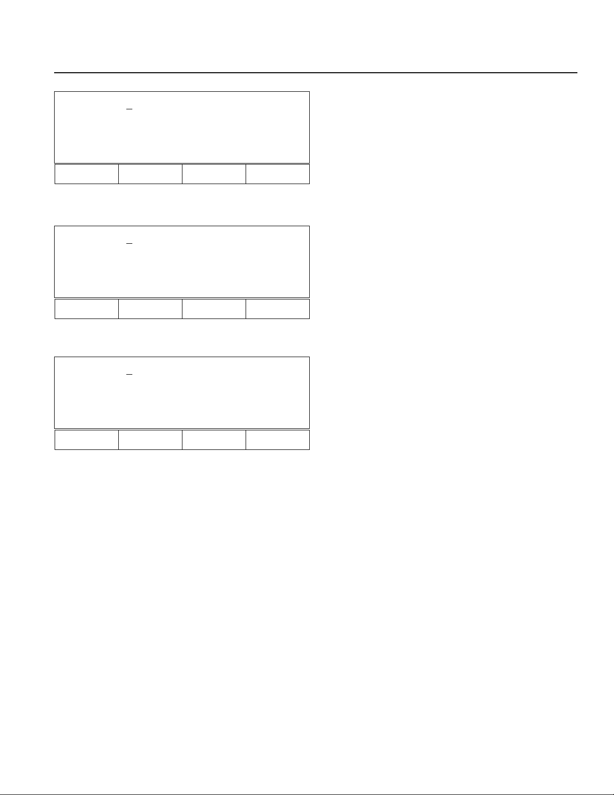
Chapter 2. Operation
Play 3 -1 [ 6 ]
Home 11
Inc Dec Clr
F1 F2 F3 F4
Play 3 [Run 1 -1]
3-2
Prog
F1 F2 F3 F4
Play 3 [Prog Status]
ERR _ STEP [ NONE ] [ RUN ]
23-2 Program Display Selection Mode (Step 23. F2)
F1- Increment Program No.
F2- Decrement Program No.
F3- Clear Program No.
23-3-1 Program Execution Status Mode (Step 23. F3)
3 -2
â
â 2: Executable, 4: Wait for completion (Input)
Executing Program No.
F3- Program Execution Status (P85. 23-3-2)
23-3-2 Program Execution Status (Step 23-3-1. F3)
F3- Return to Program Execution Status Mode
(P85. 23-3-1).
Stat
F1 F2 F3 F4
Page 85
Page 91

Chapter 2. Operation
Play 3 [Prog Status]
ERR _ STEP [ NONE ] [ RUN ]
In Out Flag
F1 F2 F3 F4
Play 012345678 (In)
000 -> 001000000 <-009
010 -> 000000000 <--019
Inc Dec
F1 F2 F3 F4
Play 012345678 (Out)
300 -> 010000000 <-309
310 -> 000000000 <- 319
Inc Dec
23-4 Input/Output, Flag Status Display Mode (Step
23. F4)
F1- Input Status Display Mode (P86. 23-4-1)
F2- Output Status Display Mode (P86. 23-4-2)
F3- Flag Status Display Mode (P86. 23-4-3)
23-4-1 Input Status Display Mode (Step 23-4. F1)
Display In 002 is ON.
0 0 1 0 0 0 0 0 0 0
â
â â
000 001 002 009
23-4-2 Output Status Display Mode (Step 23-4. F2)
Display Out 301 is ON.
ß Port No.
F1 F2 F3 F4
Play 012345678 (Flag)
600 -> 000000000 <-609
610 -> 000000000 <- 619
Inc Dec
F1 F2 F3 F4
23-4-3 Flag Status Display Mode (Step 23-4. F3)
Page 86
Page 92

Chapter 2. Operation
7. Simple Application Program Example
2-Axis actuator moves back and forth between point 1 and point 2.
• Application Program
• Position Data
(LCD Display) (Operation)
IA Super.SEL
Teach 01/13/95
Comm and Operand 1 Comm ent
HOM E 11 X and Y axis homing (Servo ON)
VE L 1 00 Velocity settin g 1 00m m /se c
AC C 0.3 Ac cele ration se tting 0 .3G
TAG 1 Assigns the target for GOTO command
MOV L 1 Moves to position number 1
MOV L 2 Moves to position number 2
GOTO 1 Jumps to TAG 1
Position Number X Axis Y Axis
1 100.000 100.000
2 10.000 10.000
1. Initial Display
Press F1 to start.
Start (blinking)
F1 F2 F3 F4
IA Super.SEL
Teach 01/13/95
Main V2.20 03/06/95
Start (blinking)
F1 F2 F3 F4
Mode Select
Prog Play Parm Test
F1 F2 F3 F4
2. Controller ROM Version Display
Press F1 to start.
3. Mode Selection Display
Press F1 to select Prog Mode.
Page 87
Page 93
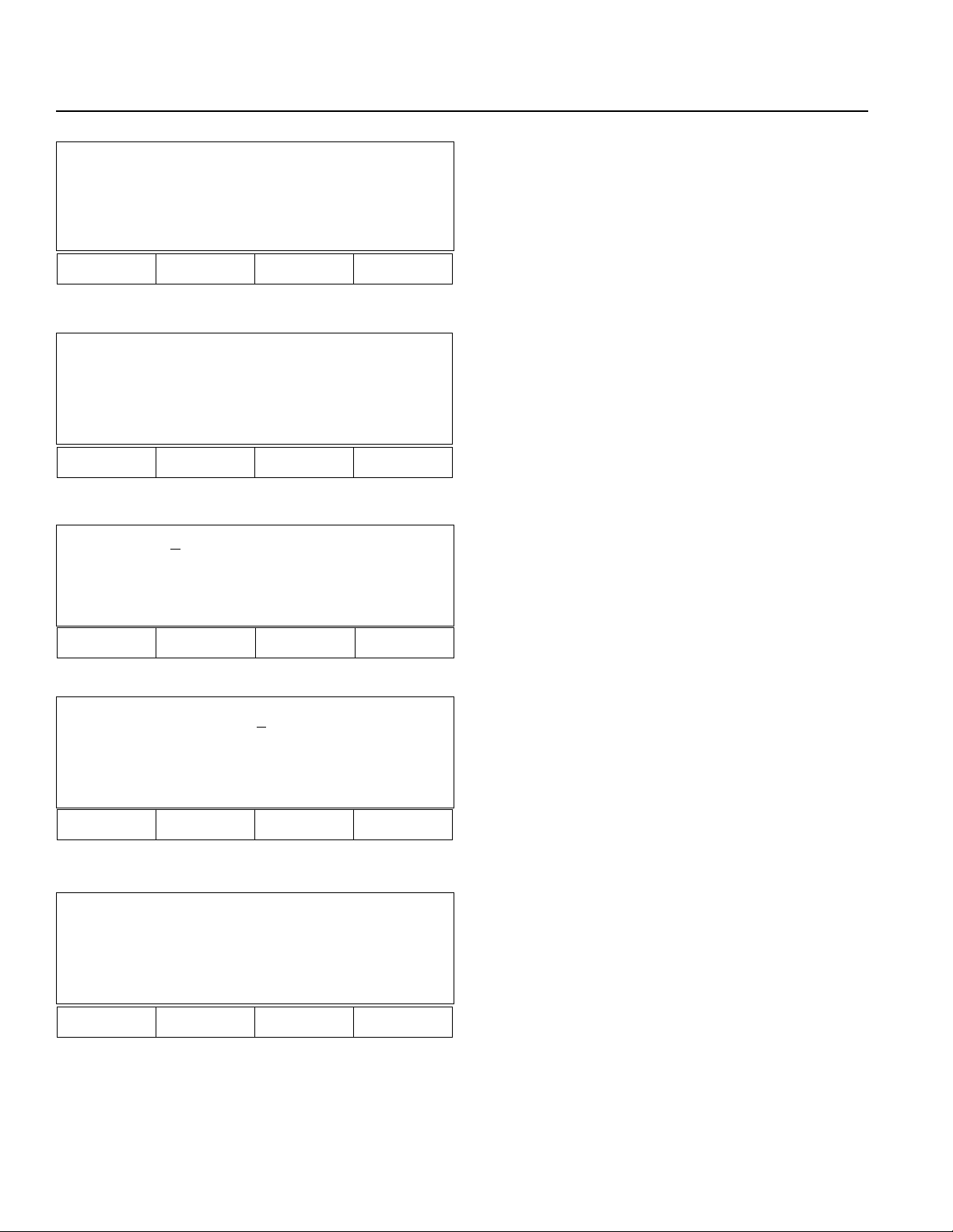
Chapter 2. Operation
Prog
Posi Aprg
F1 F2 F3 F4
Aprg
Edit Copy
F1 F2 F3 F4
Edit 1- 0 [ 0]
Inc Dec Clr Dec
F1 F2 F3 F4
4. Program Mode Display
Press F2 to select Aprg (Application Program).
5. Super SEL Programming Display
Press F1 to select Edit Mode to bring up Super SEL
program, modify, add, insert, or erase.
6. Super SEL Programming Edit Mode
Press 1 (Program number 1), then press return key.
When the program number selected exists, the display
shows the first step number. If the program number
selected does not exist, a space will appear.
Edit 1- 1 [ 0]
Inc Dec Clr etc
F1 F2 F3 F4
Edit 1- 1 [ 0]
ABPG ACC ADD AND
F1 F2 F3 F4
7. Press return key.
8. Press "." (decimal point) or "-" (minus) repeatedly until
HOME appears.
Page 88
Page 94
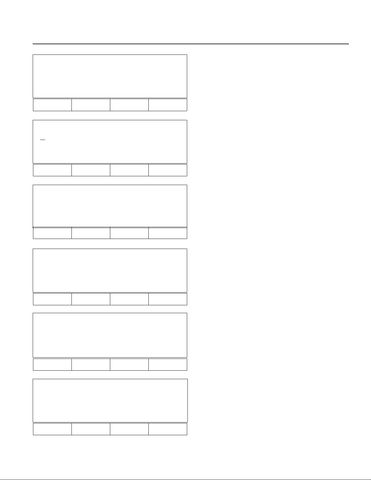
Chapter 2. Operation
Edit 1- 1 [ 0]
GOTO GRP HOLD HOME
F1 F2 F3 F4
9. Press F4 to select HOME.
Edit 1- 1 [ 0]
HOME
GOTO GRP HOLD HOME
F1 F2 F3 F4
Edit 1- 1 [ 0]
HOME _
* BS Clr
F1 F2 F3 F4
Edit 1- 1 [ 0]
HOME 11
* BS Clr
10. Press RETURN key.
11. Press "1" two times to home X and Y axes simultaneously.
12. Press return key 3 times.
F1 F2 F3 F4
Edit 1- 1 [ 0]
HOME 11
Clr Wrt
F1 F2 F3 F4
Edit 1- 2 [ 0]
-
GOTO GRP HOLD HOME
F1 F2 F3 F4
13. Press F4 (Wrt: Writing).
14. Press "." (decimal point) repeatedly until VEL appears
on display.
Repeat the same process after step 9 to input commands.
Page 89
Page 95
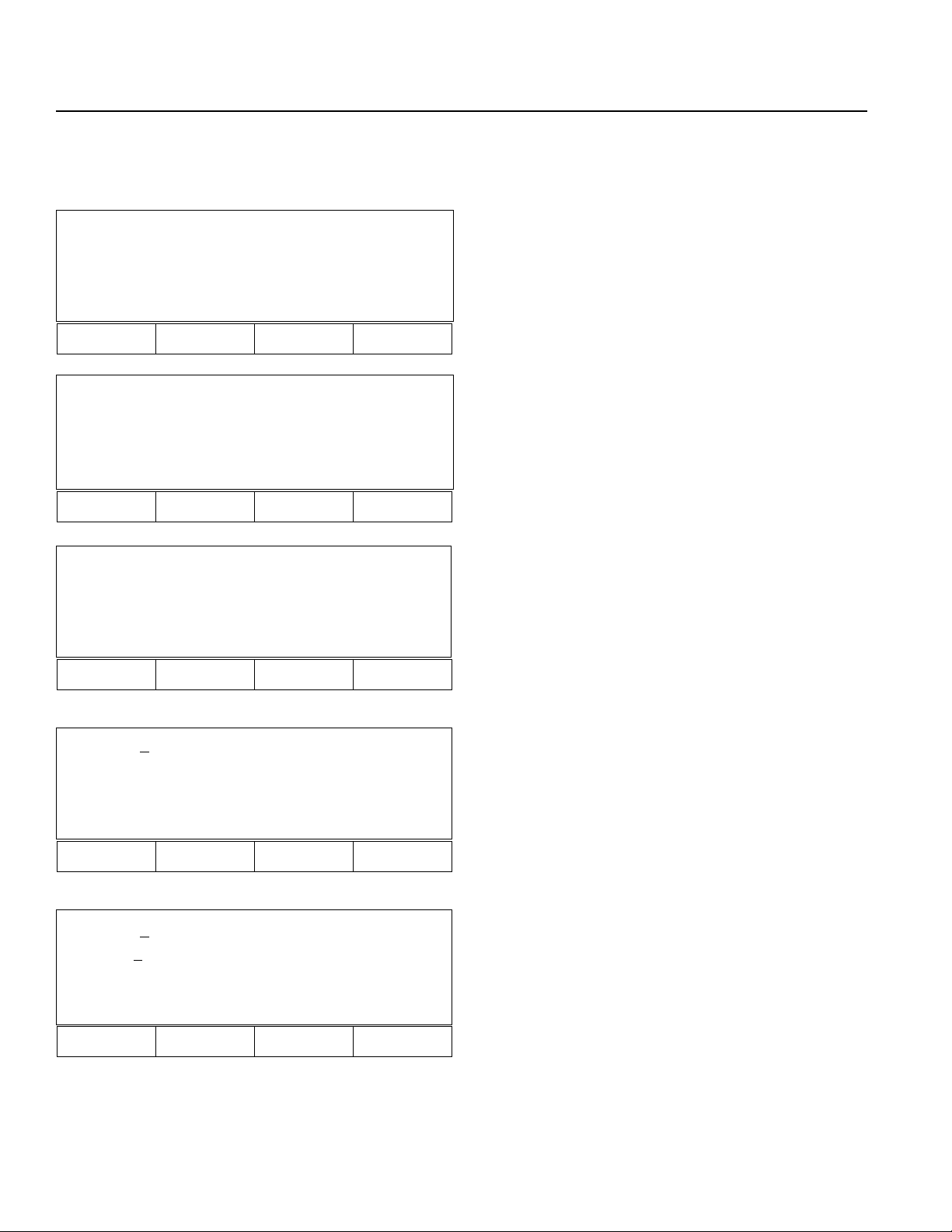
Chapter 2. Operation
When programming is completed, press ESC key repeatedly until mode selection display appears.
Next, position data will be input.
Mode Select
Prog Play Parm Test
F1 F2 F3 F4
Prog
Posi Aprg
F1 F2 F3 F4
Posi
Mdi Teac Step Etc
15. Mode Selection Display
Press F1 to select Prog (Program) Mode.
16. Program Mode
Press F1 to select Position data.
17. Position Data Editing (Go back to the display in Step
4, then press F1).
Press F1 to select Mdi Mode (position data direct
input).
F1 F2 F3 F4
Mdi - 1 No 1 [ 1 ] - 2
Inc Dec Clr Del
F1 F2 F3 F4
Mdi - 1 No 1 [ 1 ] - 2
xxxx.xx
x xxxx.xxx
Wrt Can Clr Etc
F1 F2 F3 F4
18. Mdi Mode
Press 1 for position data number 1, then press the RETURN key.
19. Press 100, then press RETURN key for X axis position
data. Press 100, then press RETURN for Y axis
position data.
Press F1 (Wrt: Writing) to save position data number 1
(100,100).
*Repeat the same process to input position data number
2.
Page 90
Page 96

Chapter 2. Operation
Part 3 System Operation
Operating Mode Summary
There are four operating modes in the Super SEL Controller System. Of these, two are primarily used for program debugging/trial operation and the remainng two are used in general applications at the factory site. The first two modes are: 1)
operation from a teaching pendant and 2) operation from the PC interface software. These are used for simple operating
checks. For the PC interface software mode, please read the operating manual that comes with the software. The latter two
modes are: 3) automatic operation based on parameter settings and 4) operation based on selection of external signals. In
the following sections, we will explain the operating modes except for 2, the PC software mode.
1. Automatic start using the parameters
Enter the number of the program you wish to start automatically in the controller parameter named "Automatic Start
Program." After doing this, the program that was entered will start running automatically when the controller is reset
or when it is powered up again after an emergency stop. This parameter can be set with the teaching pendant or the PC
interface software.
! Things to remember when using the automatic start program
When you use an automatic start program, the sudden startup of the servo actuator can startle the operator. As a safety
precaution, always use an interlock such as inserting a check signal at the beginning of the program so it will only
start up after it receives the signal.
If you wish to run several programs at the same time, write the command to run the other programs using the [EXPG]
command signal at the start of the primary automatic program.
Teaching
pendant
PC interface
software
Super SEL
controller
Start
Start
Automatic start
using parameters
External
start input
Start
Page 91
Page 97
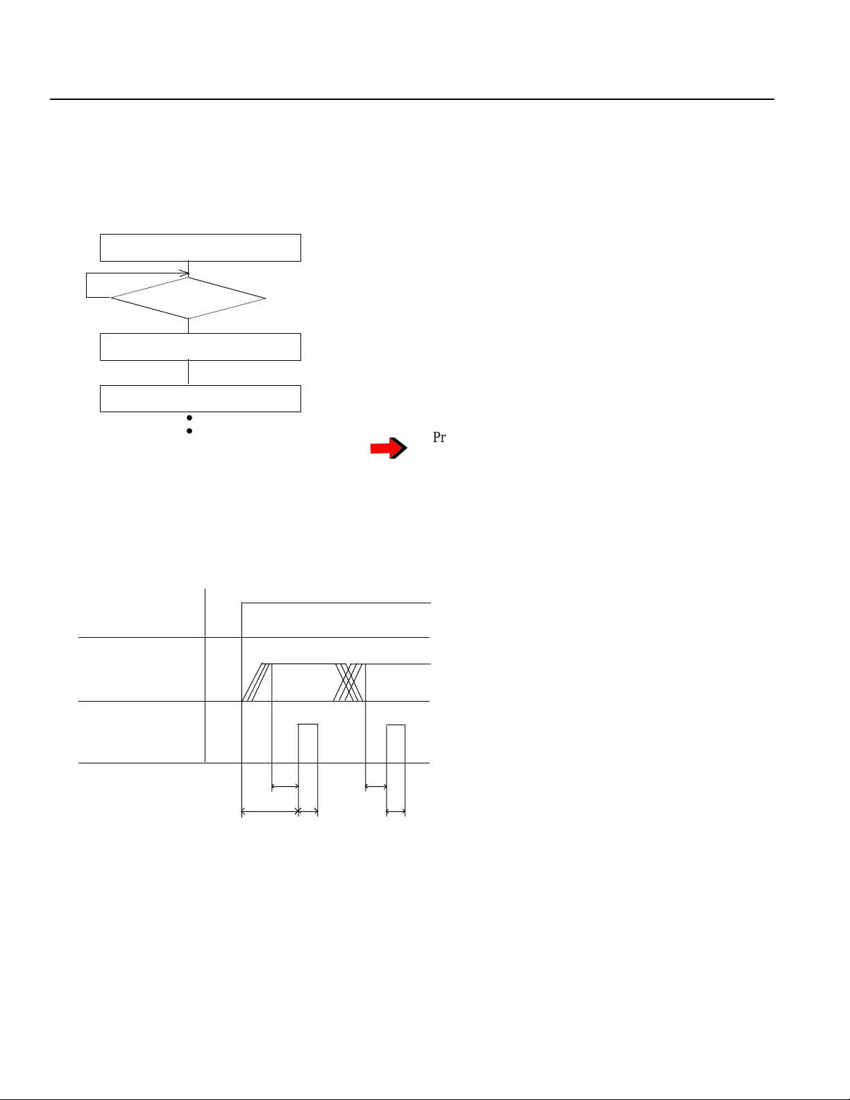
Chapter 2. Operation
2. External Start Operating Mode
Select Program No. from external unit, then input start signal.
Flow Chart
Controller Power ON
No
Ready (301) ON
Program No. Input
External Start (000) Input
Selected Program No. will start.
Timing Chart
Ready output
Program no.
input
Yes
○○
Power on
Program No. can be input before the Ready prompt.
The BCD code is input at input signal numbers 8~14.
Program No. will be displayed on the front panel of the
controller and the [AUTO] mode LED will light up.
T1: Time from ready output ON to start input
Min. 30msec
T2: Time from program No. input to external
start input
Min. 30msec
External start
input
T1
T2
T3
T3: External start input
Min. 30msec
T2
T3
Page 92
Page 98

Chapter 2. Operation
3. Teaching Pendant Operating Mode
Program is executed using the Teaching Pendant Play Mode.
Play Mode
Play 1- 1 [ 50]
MOVP 1
699 A N499
Inc Dec Clr
F1 F2 F3 F4
Play 1- 1 [ 50]
MOVP 1
699 A N499
Show Go Stat HLT
F1 F2 F3 F4
Play Mode (Operation)
1. Play Program Input Mode
Input the program to be executed (stopped).
2. Program Execution or Program Stop Selection
Designate program execution or stop.
F1 - (Show) Supervise (when the designated
program is already executing.)
F2 - (Go) Execution
F3 - (Status) Display status. (Program can be
executed or stopped after checking the status.)
F4 - (Hlt) Stop the program.
(Press F2 to execute a designated program)
4. Dedicated Input/Output Signal
(1) Dedicated Inputs
External Start This is the signal for external start. The port for this signal is (mmm).
Reads the program number and starts the program.
Program Selection Selects the program number for external start using BCD code input.
PRG 1~ External start signal is input and can be used as a user input after the program starts.
Ports 8~14 are used for this.
Emergency Stop Emergency Stop Signal
Servos and all user outputs turn OFF and alarm output turns ON.
This signal is Port 002.
System Reserve This should never be used as a User Input.
(2) Dedicated Outputs
Alarm Output Turns ON in case of Emergency Stop input or when an alarm occurs
(Error Code A?). This signal is Port 300.
another letter appears here.
Ready Output Turns ON after a few seconds when power is turned ON.
Turns OFF when alarm output is ON.
This signal is Port 301.
Note: These 2-dedicated outputs can be turned ON and OFF in the program.
Page 93
Page 99

Chapter 3. Multi-tasking
Part 1 Real-time Multi-tasking
1. Super SEL Programming Language
The Super SEL employs a 32 bit RISC CPU operated by a high speed operating system (OS). The Super SEL can control
an entire system, including not only the actuators but also peripheral devices. The Super SEL enables the user to design an
efficient automation system without learning various types of programming languages.
The original SEL language has been improved to what is now Super SEL language. In particular, the "Multi Tasking"
feature allows for high speed control of multi programs and I/O. Programming is so simple that even non-technical users
can write a parallel processing program.
General system
Robot control
device
Robot language
If....Then....Else....
MOVP P10
DOUT (310) = 1B
Super SEL system
Super SEL
controller
Robot
Interlocking wiring
Wiring is also simple
Conveyor
Control device
for peripherals
PLC
Ladder diagram
•
•
•
•
•
Super SEL language
N 600 MOVL 10 310
Page 94
Page 100

Chapter 3. Multi-tasking
2. Multi-tasking
"Multi Tasking" simply means running multiple programs concurrently.
Let us consider a screwdriving robot system as an example. The following screwdriving system is composed of two
actuators (X axis and Y axis) and a screwdriver with the part feeder.
System Flow
[Screwdriving] Parts Feeder
Move
Screw Preparation
↓
Screw
↓
X,Y Move
Screw Preparation
↓
Screw
The following is a simple flowchart that shows the multi-tasking operation used when it is necessary to move a part
feeder at the same time the XY actuator is operating.
Program 1 Start
Move
Tighten screw
Program 2
Start
Parts feeder ON
Screw OK
Move
Tighten screw
Parts feeder OFF
Not enough screws
Timer
Page 95
 Loading...