

Page 1

Operation Manual Fourteenth Edition
SCON Controller
Page 2

Page 3

Please Read Before Use
Thank you for purchasing our product.
This Operation Manual explains the handling methods, structure and maintenance of this product, among others,
providing the information you need to know to use the product safely.
Before using the product, be sure to read this manual and fully understand the contents explained herein to
ensure safe use of the product.
The CD that comes with the product contains operation manuals for IAI products.
When using the product, refer to the necessary portions of the applicable operation manual by printing them out
or displaying them on a PC.
After reading the Operation Manual, keep it in a convenient place so that whoever is handling this product can
reference it quickly when necessary.
[Important]
This Operation Manual is original.
The product cannot be operated in any way unless expressly specified in this Operation Manual. IAI shall
assume no responsibility for the outcome of any operation not specified herein.
Information contained in this Operation Manual is subject to change without notice for the purpose of
product improvement.
If you have any question or comment regarding the content of this manual, please contact the IAI sales
office near you.
Using or copying all or part of this Operation Manual without permission is prohibited.
The company names, names of products and trademarks of each company shown in the sentence s are
registered trademarks.
Page 4

Page 5

1. PC Software and Teaching Pendant Models
New functions have been added to the entire SCON controller series.
To support these new features, the communication protocol has been changed to the general Modbus
(Modbus-compliant) mode. As a result, the existing PC software programs and teaching pendants
compatible with RCS/E-Con controllers can no longer be used.
If you are using this controller, use a compatible PC software program and/or teaching pendant selected
from the following models.
Model Remarks
PC software (with RS232C
communication cable)
PC software (with USB communication
cable)
Teaching pendant CON-T
Teaching pendant RCM-T
Simple teaching pendant RCM-E
Data setting unit RCM-P
Touch panel display RCM-PM-01
2. Recommendation for Backing up Latest Data
This product uses nonvolatile memory to store the position table and parameters. Normally the memory will
retain the stored data even after the power is disconnected. However, the data may be lost if the nonvolatile
memory becomes faulty.
(We strongly recommend that the latest position table and parameter data be backed up so that the data
can be restored quickly in the event of power failure, or when the controller must be replaced for a given
reason.)
The data can be backed up using the following methods:
[1] Save to a CD or FD from the PC software.
[2] Hand write the position table and parameter table on paper.
3. Using a Rotary Actuator of Multi-rotation Specification
Rotary actuators available in the multi-rotation specification allow the user to select the multi-rotation mode
or limited-rotation mode using a parameter.
For the parameter setting, refer to 3.2.5, “Linear/Rotary Control” under 3, “Parameter Settings” in Appendix.
When using a rotary actuator of multi-rotation specification, the user should take note of the following
points:
[1] Rotational axes of absolute specification do not support the index mode. Accordingly, these axes
cannot perform multi-rotation operations.
[2] In solenoid valve mode 2 [3-point type]: PIO pattern 5 (parameter No. 25), rotary operations cannot be
performed by means of relative coordinate specification.
Actuator
RCM-101-MW
RCM-101-USB
All are compatible with existing RCS/E-Con
controllers.
Cannot be connected to conventional RCS
controller
Applicable models
RS-30/60
RCS2-RT6/RT6R/RT7/RT7R
RCS2-RTC8L/RTC8HL/RTC10L/RTC12L
CAUTION
Page 6

±
2
6
3
1
Precautions
Please use rotary actuators of multi-rotation specification within the range where the following formula is
satisfied. Moreover, the maximum rotation angle is ±9999 [deg]
23
±2
Maximum rotation angle [deg]
≥
Unit Travel Distance [deg/pulse]
• Maximum rotation angle: Set the usage conditions (maximum -9999 to 9999 [deg]).
Note 1 :The following models can not be rotated up to ±9999.99 [deg].
deceleration
ratio
1/24
1/30
1/50
1/100
Maximum rotation angle
corresponding model
[deg]
±7679.99 RCS2-RTC8、RCS2-RTC10
±6143.99
±3685
RCS2-RTC12
RS-30、RS-60
±1842
• Unit movement: The amount of movement per command pulse.
Example) In case RCS2-RTC8L-I-12-24(deceleration ratio:1/24) is operated maximum rotation
angle 6000 [deg].
223
Maximum rotation angle [deg]
≥
Unit Travel Distance [deg/pulse]
23
≥
±2
Maximum rotation angle [deg]
23
±2
6000
≥
23
±2
≥
553600
×
16384
60
×
4
Therefore, the actuator can be operated in this case.
(NOTE1)
(maximum software stroke limit).
No. of Encoder Pluses [pulse/rev]
×
360[deg/rev] × Rotary Axis
deceleration
Ratio
Page 7
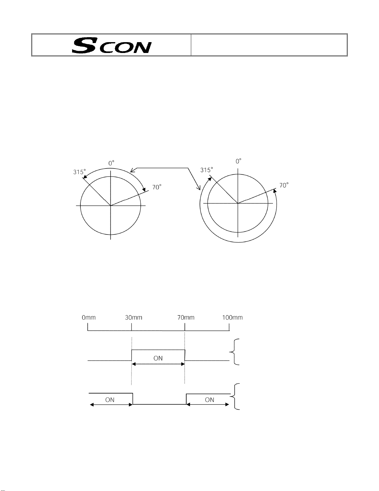
About zone function change
Applicable application version: From V001E
In zone signal settings, it is now valid to specify plus side zone setting smaller than minus side zone setting.
Up to V001D: Zone signals are not output in the case of plus side zone settin g minus side zone setting only.
From V001E: Zone signals are not output in the case of plus side zone settin g = minus side zone setting o nly.
With this arrangement, zone output is enabled even if the zone single ON range spans over 0 in the index mode
of rotary actuators.
An example is shown below.
[In index mode of rotary actuators]
Setting value
Plus side zone setting: 70
Minus side zone setting: 315
[In case of translation axis]
Current position
Zone signal output
Zone signal output
Range of
zone signal ON
Setting value
Plus side zone setting: 315
Minus side zone setting: 70
Setting value
Plus side zone setting: 70 mm
Minus side zone setting: 30 mm
Setting value
Plus side zone setting: 30 mm
Minus side zone setting: 70 mm
CAUTION
Page 8

Page 9

Table of Contents
Safety Guide....................................................................................................Pre-1
Chapter 1 Introduction .........................................................................................1
1. Overview.................................................................................................................................1
1.1 Introduction........................................................................................................................... 1
1.2 SCON Functions ..................................................................................................................1
1.3 How to Read the Model Specification ..................................................................................4
1.4 System Configuration........................................................................................................... 5
1.5 Procedure from Unpacking to Test Operation and Adjustment............................................ 6
1.6 Warranty Period and Scope of Warranty.............................................................................. 8
2. Specifications..........................................................................................................................9
2.1 Basic Specifications..............................................................................................................9
2.2 Name and Function of Each Part....................................................................................... 10
2.3 External Dimensions ..........................................................................................................21
3. Installation and Wiring...........................................................................................................23
3.1 Installation Environment..................................................................................................... 23
3.2 Heat Radiation and Installation ..........................................................................................23
3.3 Noise Elimination Measures and Grounding...................................................................... 24
3.4 Wiring the Power Supply....................................................................................................26
3.5 Connecting the Actuator..................................................................................................... 28
3.6 Connecting the PIO Cable (I/O)......................................................................................... 29
3.7 External Input/Output Specifications.................................................................................. 30
3.8 Connecting the Emergency Stop Input (Wiring to the System I/O Connector).................. 32
3.9 Connecting the Regenerative Unit (RB)............................................................................. 48
3.10 Connecting the Brake Box (RCB-110-RA13-0)..............................................................50
Chapter 2 Positioner Mode................................................................................52
1. I/O Signal Control and Signal Functions...............................................................................52
1.1 PIO Patterns and Signal Assignments ...............................................................................52
1.2 Connecting the I/O Cable................................................................................................... 61
1.3 Details of I/O Signal Functions...........................................................................................67
2. Data Entry.............................................................................................................................77
2.1 Description of Position Table..............................................................................................77
2.2 Explanation of Modes......................................................................................................... 84
2.3 Power-saving Modes at Standby Positions........................................................................ 94
3. Operation..............................................................................................................................96
3.1 How to Start........................................................................................................................96
3.2 How Return Operation...................................................................................................... 107
3.3 Positioning Mode (Back and Forth Movement between Two Points)...............................109
3.4 Push & Hold Mode ............................................................................................................111
3.5 Speed Change during Movement..................................................................................... 114
3.6 Operation at Different Acceleration and Deceleration Settings........................................ 116
3.7 Pause ............................................................................................................................... 118
3.8 Zone Signal Output .......................................................................................................... 120
3.9 Incremental Moves........................................................................................................... 123
Page 10

Jogging/Teaching Using PIO........................................................................................ 129
3.10
3.11 Operations in Solenoid Valve Mode 1 [7-point Type]....................................................131
3.12 Operations in Solenoid Valve Mode 2 [3-point Type]....................................................135
Chapter 3 Pulse-train Input Mode....................................................................142
1. Overview.............................................................................................................................142
1.1 Features ........................................................................................................................... 142
1.2 Standard Accessories.......................................................................................................143
1.3 Options .............................................................................................................................143
2. Wiring..................................................................................................................................147
2.1 External Connection Diagram..........................................................................................147
2.2 Command Pulse-train Input Specifications ......................................................................148
2.3 Feedback Pulse Output Part ............................................................................................149
3. I/O Signal Control and Signal Functions.............................................................................150
3.1 Input Signals.....................................................................................................................150
3.2 Output Signals..................................................................................................................156
4. How to Switch to the Pulse-train Control Mode...................................................................161
5. Parameters .........................................................................................................................162
5.1 Parameter Settings Required for Operation..................................................................... 162
5.2 Effective Parameters in the Pulse-train Mode.................................................................. 166
* Appendix ..........................................................................................................169
1. Actuator Specification List...................................................................................................169
2. Battery Backup Function.....................................................................................................174
2.1 Absolute-encoder Backup Battery....................................................................................175
3. Parameter Settings.............................................................................................................177
3.1 Parameter Table...............................................................................................................177
3.2 Detail Explanation of Parameters.....................................................................................179
4. PC/Teaching Pendant Connection Method in Multi-axis Configurations.............................202
4.1 Connection Example........................................................................................................202
4.2 Name and Function of Each Part of the SIO Converter...................................................203
4.3 Address Switch.................................................................................................................205
4.4 Connection Cables........................................................................................................... 205
4.5 Detail Connection Diagram ..............................................................................................206
5. Troubleshooting..................................................................................................................207
5.1 Action to Be T aken upon Occurrence of Problem............................................................207
5.2 Alarm Level Classification................................................................................................208
5.3 Alarm Description Output Using PIO................................................................................209
5.4 Alarm Description and Cause/Action ............................................................................... 211
5.5 Messages Displayed during Operation Using the Teaching Pendant..............................220
5.6 Specific Problems.............................................................................................................222
6. Basic Example of Positioning Sequence ............................................................................224
Recording of Parameters ...........................................................................................................227
Change History...................................................................................................229
Page 11

Safety Guide
This “Safety Guide” is intended to ensure the correct use of this product and prevent dangers and property
damage. Be sure to read this section before using your product.
Regulations and Standards Governing Industrial Robots
Safety measures on mechanical devices are generally classified into four categori es under the International
Industrial Standard ISO/DIS 12100, “Safety of machinery,” as follows:
Safety measures Inherent safety design
Protective guards --- Safety fence, etc.
Additional safety measures --- Emergency stop device, etc.
Information on use --- Danger sign, warnings, operation manual
Based on this classification, various standards are established in a hierarchical manner unde r the International
Standards ISO/IEC. The safety standards that apply to industrial robots are as follows:
Type C standards (individual safety standards) ISO10218 (Manipulating industrial robots – Safety)
JIS B 8433
(Manipulating industrial robots – Safety)
Also, Japanese laws regulate the safety of industrial robots, as follows:
Industrial Safety and Health Law Article 59
Workers engaged in dangerous or harmful operations must recei ve special education.
Ordinance on Industrial Safety and Health
Article 36 --- Operations requiring special education
No. 31 (Teaching, etc.) --- Teaching and other similar work involving industrial robots (exceptions
apply)
No. 32 (Inspection, etc.) --- Inspection, repair, adjustment and similar work involving industrial robots
(exceptions apply)
Article 150 --- Measures to be taken by the user of an industrial robot
Pre-1
Page 12

Requirements for Industrial Robots under Ordinance on Industrial Safety and
Health
Work area Work condition Cutoff of drive source Measure Article
Signs for starting operation Article 104 Outside
Installation of railings, enclosures,
etc.
Sign, etc., indicating that work is in
progress
Preparation of work rules Article 150-3
Measures to enable immediate
stopping of operation
Sign, etc., indicating that work is in
progress
Provision of special education Article 36-31
Checkup, etc., before
commencement of work
To be performed after stopping the
operation
Sign, etc., indicating that work is in
progress
Preparation of work rules Article 150-5
Measures to enable immediate
stopping of operation
Sign, etc., indicating that work is in
progress
Provision of special education
(excluding cleaning and lubrication)
Article 150-4
Article 150-3
Article 150-3
Article 150-3
Article 151
Article 150-5
Article 150-5
Article 150-5
Article 150-5
Article 36-32
movement
range
Inside
movement
range
During
automatic
operation
During
teaching, etc.
During
inspection, etc.
Not cut off
Cut off (including
stopping of operation)
Not cut off
Cut off
Not cut off (when
inspection, etc., must
be performed during
operation)
Pre-2
Page 13

Applicable Modes of IAI’s Industrial Robot
Machines meeting the following conditions are not classified as industrial robots according to Notice of Ministry
of Labor No. 51 and Notice of Ministry of Labor/Labor Standards Office Director (Ki-Hatsu No. 340):
(1) Single-axis robo with a motor wattage of 80 W or less
(2) Combined multi-axis robot whose X, Y and Z-axes are 300 mm or shorter and whose rotating part, if
any, has the maximum movement range of within 300 mm
(3) Multi-joint robot whose movable radius and Z-axis are within 300 mm
Among the products featured in our catalogs, the following models are classified as industrial robots:
1. Single-axis ROBO Cylinders
RCS2/RCS2CR-SS8
2. Single-axis robots
The following models whose stroke exceeds 300 mm and who se motor capacity also exceeds 80 W:
ISA/ISPA, ISDA/ISPDA, ISWA/ISPWA, IF, FS, NS
3. Linear servo actuators
All models whose stroke exceeds 300 mm
4. Cartesian robos
Any robot that uses at least one axis corresponding to one of the models specified in 1 to 3
5. IX SCARA robots
All models whose arm length exceeds 300 mm
(All models excluding IX-NNN1205/1505/1805/2515, NNW2515 and NNC1205/1 505/1805/2515)
whose stroke exceeds 300 mm
3
including the tip of the rotating part
Pre-3
Page 14

Notes on Safety of Our Products
Common items you should note when performing each task on any IAI robot are explained below.
No. Task Note
1 Model
selection
2 Transportation
3 Storage/
preservation
4 Installation/
startup
This product is not planned or designed for uses requiring high degrees of safety.
Accordingly, it cannot be used to sustain or support life and must not be used in the
following applications:
[1] Medical devices relating to maintenance, management, etc., of life or health
[2] Mechanisms or mechanical devices (vehicles, railway facilities, aircraft facilities, etc.)
intended to move or transport people
[3] Important safety parts in mechanical devices (safety devices, etc.)
Do not use this product in the following environments:
[1] Place subject to flammable gases, ignitable objects, flammables, explosives, etc.
[2] Place that may be exposed to radiation
[3] Place where the surrounding air temperature or relative humidity exceeds the specified
range
[4] Place subject to direct sunlight or radiated heat from large heat sources
[5] Place subject to sudden temperature shift and condensation
[6] Place subject to corrosive gases (sulfuric acid, hydrochloric acid, etc.)
[7] Place subject to excessive dust, salt or iron powder
[8] Place where the product receives direct vibration or impact
Do not use this product outside the specified ranges. Doing so may significantly shorten
the life of the product or result in product failure or facility stoppage.
When transporting the product, exercise due caution not to bump or drop the product.
Use appropriate means for transportation.
Do not step on the package.
Do not place on the package any heavy article that may deform the package.
When using a crane of 1 ton or more in capacity, make sure the crane operators are
qualified to operate cranes and perform slinging work.
When using a crane, etc., never hoist articles exceeding the rated load of the crane, etc.
Use hoisting equipment suitable for the article to be hoisted. Calculate the load needed
to cut off the hoisting equipment and other loads incidental to equipment operation by
considering a safety factor. Also check the hoisting equipment for damage.
Do not climb onto the article while it is being hoisted.
Do not keep the article hoisted for an extended period of time.
Do not stand under the hoisted article.
The storage/preservation environment should conform to the installation environment.
Among others, be careful not to cause condensation.
(1) Installing the robot, controller, etc.
Be sure to firmly secure and affix the product (including its work part).
If the product tips over, drops, malfunctions, etc., damage or injury may result.
Do not step on the product or place any article on top. The product may tip over or the
article may drop, resulting in injury, product damage, loss of/drop in product
performance, shorter life, etc.
If the product is used in any of the following places, provide sufficient shielding
measures:
[1] Place subject to electrical noise
[2] Place subject to a strong electric or magnetic field
[3] Place where power lines or drive lines are wired nearby
[4] Place subject to splashed water, oil or chemicals
Pre-4
Page 15

No. Task Note
4 Installation/
startup
(2) Wiring the cables
Use IAI’s genuine cables to connect the actuator and controller or connect a teaching
tool, etc.
Do not damage, forcibly bend, pull, loop round an object or pinch the cables or place
heavy articles on top. Current leak or poor electrical continuity may occur, resulting in
fire, electric shock or malfunction.
Wire the product correctly after turning off the power.
When wiring a DC power supply (+24 V), pay attention to the positive and negative
polarities.
Connecting the wires in wrong polarities may result in fire, product failure or
malfunction.
Securely connect the cables and connectors so that they will not be disconnected or
come loose. Failing to do so may result in fire, electric shock or product malfunction.
Do not cut and reconnect the cables of the product to extend or shorten the cables.
Doing so may result in fire or product malfunction.
(3) Grounding
Be sure to provide class D (former class 3) grounding for the controller. Grounding is
required to prevent electric shock and electrostatic charges, improve noise resistance
and suppress unnecessary electromagnetic radiation.
(4) Safety measures
Implement safety measures (such as installing safety fences, etc.) to prevent entry into
the movement range of the robot when the product is moving or can be moved.
Contacting the moving robot may result in death or serious injury.
Be sure to provide an emergency stop circuit so that the product can be stopped
immediately in case of emergency during operation.
Implement safety measures so that the product cannot be started only by turning on the
power. If the product starts suddenly, injury or product damage may result.
Implement safety measures so that the product will not start upon cancellation of an
emergency stop or recovery of power following a power outage. Failure to do so may
result in injury, equipment damage, etc.
Put up a sign saying “WORK IN PROGRESS. DO NOT TURN ON POWER,” etc.,
during installation, adjustment, etc. If the power is accidently turned on, electric shock or
injury may result.
Implement measures to prevent the work part, etc., from dropping due to a power
outage or emergency stop.
Ensure safety by wearing protective gloves, protective goggles and/or safety shoes, as
necessary.
Do not insert fingers and objects into openings in the product. Doing so may result in
injury, electric shock, product damage, fire, etc.
When releasing the brake of the vertically installed actuator, be careful not to let the
actuator drop due to its dead weight, causing pinched hands or damaged work part, etc.
5 Teaching
Whenever possible, perform teaching from outside the safety fences. If teaching must
be performed inside the safety fences, prepare “work rules” and ma ke sure the operator
understands the procedures thoroughly.
When working inside the safety fences, the operator should carry a handy emergency
stop switch so that the operation can be stopped any time when an abnormality occurs.
When working inside the safety fences, appoint a safety watcher in addition to the
operator so that the operation can be stopped any time when an abnormality occurs.
The safety watcher must also make sure the switches are not operated inadvertently by
a third party.
Put up a sign saying “WORK IN PROGRESS” in a conspicuous location.
Pre-5
Page 16

No. Task Note
5 Teaching When releasing the brake of the vertically installed actuator, be careful not to let the
actuator drop due to its dead weight, causing pinched hands or damaged lo ad, etc.
* Safety fences --- Indicate the movement range if safety fences are not provided.
6 Confirmation
operation
After teaching or programming, carry out step-by-step confirmation operation before
switching to automatic operation.
When carrying out confirmation operation inside the safety fences, follow the specified
work procedure just like during teaching.
When confirming the program operation, use the safety speed. Failure to do so may
result in an unexpected movement due to programming errors, etc., causing injury.
Do not touch the terminal blocks and various setting switches while the power is
supplied. Touching these parts may result in electric shock or malfunction.
7 Automatic
operation
Before commencing automatic operation, make sure no one is inside the safety fences.
Before commencing automatic operation, make sure all related peripherals are ready to
operate in the auto mode and no abnormalities are displayed or indicated.
Be sure to start automatic operation from outside the safety fences.
If the product generated abnormal heat, smoke, odor or noise, stop the product
immediately and turn off the power switch. Failure to do so may result in fire or product
damage.
If a power outage occurred, turn off the power switch. Otherwise, the product may move
suddenly when the power is restored, resulting in injury or product damage.
8 Maintenance/
inspection
Whenever possible, work from outside the safety fences. If work must be performed
inside the safety fences, prepare “work rules” and make sure the operator understands
the procedures thoroughly.
When working inside the safety fences, turn off the power switch, as a rule.
When working inside the safety fences, the operator should carry a handy emergency
stop switch so that the operation can be stopped any time when an abnormality occurs.
When working inside the safety fences, appoint a safety watcher in addition to the
operator so that the operation can be stopped any time when an abnormality occurs.
The safety watcher must also make sure the switches are not operated inadvertently by
a third party.
Put up a sign saying “WORK IN PROGRESS” in a conspicuous location.
Use appropriate grease for the guides and ball screws by checking the operation
manual for each model.
Do not perform a withstand voltage test. Conducting this test may result in product
damage.
When releasing the brake of the vertically installed actuator, be careful not to let the
actuator drop due to its dead weight, causing pinched hands or damaged work part, etc.
* Safety fences --- Indicate the movement range if safety fences are not provided.
9 Modification The customer must not modify or disassemble/assemble the product or use
maintenance parts not specified in the manual without first consulting IAI.
Any damage or loss resulting from the above actions will be excluded from the scope of
warranty.
10 Disposal When the product becomes no longer usable or necessary, dispose of it properly as an
industrial waste.
When disposing of the product, do not throw it into fire. The product may explode or
generate toxic gases.
Pre-6
Page 17
Indication of Cautionary Information
The operation manual for each model denotes safety precautions under “Danger,” “Warning,” “Caution” a nd
“Note,” as specified below.
Level Degree of danger/loss Symbol
Danger
Warning
Caution
Note
Failure to observe the instruction will result in an
imminent danger leading to death or serious injury.
Failure to observe the instruction may result in death
or serious injury.
Failure to observe the instruction may result in injury
or property damage.
The user should take heed of this information to
ensure the proper use of the product, although failure
to do so will not result in injury.
Danger
Warning
Caution
Note
Pre-7
Page 18

CE Marking
CE Marking
If a compliance with the CE Marking is required, please follow Overseas Standards Compliance Manual
(ME0287) that is provided separately.
Pre-8
Page 19

Chapter 1 Introduction
1. Overview
1.1 Introduction
Thank you for purchasing the SCON controller.
Please read this manual carefully to handle the controller with due care while ensuring the correct operation of
the controller.
Keep this manual with you so that you can reference the applicable sections whenever necessary.
Should you encounter any trouble when actually starting up your system, also refer to the manuals for the
teaching pendant, PC software and other components included in your system, in addition to this manual.
This manual does not cover all possible operations other than normal operations, or unexpected events such as
complex signal changes resulting from use of critical timings.
Accordingly, you should consider items not specifically explained in this manual as “prohibited.”
* We have made every effort to ensure precision of the information provided in this manual. Should you find an
error, however, or if you have any comment, please contact IAI.
Keep this manual in a convenient place so it can be referenced readily when necessary.
1.2 SCON Functions
The SCON is a single-axis AC servo controller capable of controlling actuators in the position er mode or the
pulse-train input mode.
The functions of SCON are as follows:
The positioner mode and the pulse-train input mode cannot be used at the same time.
Switching of modes uses the piano switch located on the front face of the controller.
Positioner mode
Pulse-train input mode
Positioning mode [Standard type]
Teaching mode [Teaching type]
256-point mode [256-point type]
512-point mode [512-point type]
Solenoid valve mode 1 [7-point type]
Solenoid valve mode 2 [3-point type]
1
Page 20

1.2.1 Features of the Positioner Mode
In the positioner mode, one of five PIO patterns is selected using a parameter.
The number of positioning points and input/output functions vary depending on the PIO pattern selected.
The table below lists the parameter settings and corresponding PIO patterns, as well as the features of each PIO
pattern.
Parameter setting Features of PIO pattern
0 Positioning mode [Standard type]
64 positioning points are supported.
Available output functions include the moving output and zone output.
1 Teaching mode [Teaching type]
64 positioning points are supported.
Normal positioning operation can be performed, along with jogging via I/O operation
and writing of the current position to the position table.
The MODE input signal is used to switch between the normal positioning operation
mode and the teaching mode.
The zone output (set by parameters) and brake forced-release input accessible in the
standard type are not available in this type.
2 256-point mode [256-point type]
The moving output and zone output (set by parameters) accessible in the standard
type are not available in this type.
3 512-point mode [512-point type]
The moving output and zone output (set by parameters/position data) accessible in the
standard type are not available in this type.
4 Solenoid valve mode 1 [7-point type]
Seven positioning points are supported.
Direct command inputs and position complete outputs are provide d separately for
different target positions to simulate air-cylinder control.
The moving output accessible in the standard type is not available in this type.
5 Solenoid valve mode 2 [3-point type]
Three positioning points are supported.
The function of position complete output signals is different from how these signals
function in the 7-point type.
The “position detection” function, which operates just like an auto-switch of an air
cylinder, is also available.
Take note that incremental positioning commands are not supported in this mode.
2
Page 21

1.2.2 Features of the Pulse-train Input Mode
Dedicated home return signal
Home return operation is supported in this mode.
When this function is used, home return can be performed automatically without having to program a
complex sequence or use an external sensor, etc.
Brake control function
The electromagnetic brake power is supplied to the controller from a power supply different from the main
power. Since the controller controls the brake, there is no need to program a separate sequence. Also, the
electromagnetic brake can be released freely after the main power has been cut off.
Torque limiting function
The torque can be limited (a desired limit can be set by a parameter) using an external signal. When the
torque reaches the specified level, a signal will be output. This function permits push & hold operation, pressfit operation, etc.
Feed-forward control function
With this function, response can be improved in certain situations such as when the load inertia ratio is high.
Increasing the parameter value will reduce the deviation (difference between th e position command and the
position feedback), thereby improving response.
Position-command primary filter function
Soft start and stop can be achieved even when the actuator is operated in the command-pulse input mode
where acceleration and deceleration are not considered.
Feedback function
Position detection data is output using pulse trains (differential).
The current actuator position can be read in real time from the host controller.
3
Page 22

1.3 How to Read the Model Specification
<Series>
<Controller type>
C: Standard type
<Motor capacity>
20: 20W
30D: 30 W for DS
30R: 30 W for RS
60: 60W
100: 100W
150: 150W
200: 200W
200S: 200 W for linear
300S: 300 W for linear
400: 400W
600: 600W
750: 750W
<Encoder type>
I: Incremental
A: Absolute
<Option>
HA: High acceleration/deceleration specification
<Power-supply voltage>
1: Single phase 100 VAC
2: Single phase 200 VAC
<I/O cable length>
2: 2 m
3: 3 m
5: 5 m
0: Not supplied
<I/O types>
NP: NPN specification
PN: PNP specification
DV: DeviceNet specification
CC: CC-Link specification
RR: PROFIBUS connection specification
4
Page 23
A
A
r
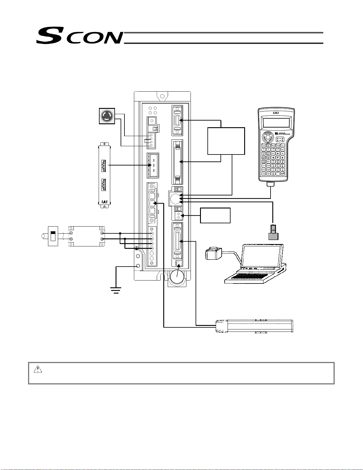
1.4 System Configuration
Regenerative
resistance unit
It may become
necessary depending
on the use condition.
Breaker
Note) Noise filter
MC1210 by
Densei-Lambda
EMG switch
Grounded
Absolute
battery
Host control
system
DC24V
bsolute battery
Brake power
supply
PC
ctuato
Teaching
pendant
Caution: The customer must provide a noise filter. A noise filter is always required at the minimum, even
when your system need not conform to the EC Directives. Also add clamp filters, etc., if necessary.
5
Page 24

1.5 Procedure from Unpacking to Test Operation and Adjustment
If you are using this product for the first time, carry out each step by referring to the procedure below to ensure
that all necessary items are checked and all wires are connected corre ctly. The procedure below covers the flow
from unpacking to trial operation using a PC or teaching pendant.
(1) Check the content in the package
If you found any missing part or part specified for a different model, please contact your dealer.
* Check that the model specification pasted on the controller and the model specification of the delivered
actuator match.
Controller SCON-*-
Motor cable
Encoder cable
I/O flat cable
Pulse-train control connector plug: 10114-3000PE (Sumitomo 3M)
Pulse-train control connector housing: 10314-52F0-008 (Sumitomo 3M)
Actuator
Options
Pulse converter AK-04, JM-08
Teaching pendant COM-T RCM-T RCM-E RCM-P
PC software RCM-101-MW, RCM-101-USB
Regenerative unit
Touch panel display RCM-PM-01 (supported from system software version V0015)
(2) Installation
[1] Affix the actuator.
[2] Install the controller.
(3) Wiring/connection
Connect the motor cable and encoder cable.
Wire the AC power supply.
Connect the grounding wire to ground.
Wire the emergency stop circuit.
Connect the I/O flat cable (wiring with the host PLC and 24-V I/O power supply).
Connect the 24-V brake power supply (only if the actuator is equipped with a brake).
Connect the regenerative unit(s). The need for regenerative unit will vary depending on the use condition.
(4) Turn on the power and check for alarms
[1] If the SCON is to be used in the positioner mode, set piano switch 1 to the OFF position (ri ght side).
[2] Connect the PC or teaching pendant, and then set the AUTO/MANU switch to the MANU position.
[3] Input the 24-V I/O power.
[4] If the actuator is equipped with a brake, turn on the 24-V power supply for the brake.
[5] Input the AC power (control power, drive power).
If an emergency stop is actuated, the EMG LED indicator will illuminate in red.
If an alarm generates, the ALM LED indicator will illuminate in orange. Check the nature of the alarm using the
PC or teaching pendant and remove the cause by referring to Appendix 5, “Troubleshooting.”
System I/O shorting connector
Power connector
Brake connector
6
Page 25

(5) Set parameters
Before the 24-V I/O power supply is connected, PIO power monitor can be disabled temporarily by changing
the applicable parameter setting.
Parameter No. 74, “PIO power monitor”: 0 (Enable) 1 (Disable)
Note) After the 24-V I/O power supply has been connected, be sure to reset parameter No. 74 to “0” to
enable PIO power monitor.
If the host PLC or other host controller is not yet wired and the servo-on signal cannot be input, the servo-on
input can be disabled temporarily by changing the applicable parameter setting.
Parameter No. 21, “Servo-on input”: 0 (Enable) 1 (Disable)
Note) After the host PLC, etc., has been wired, be sure to reset parameter No. 21 to “0” to enable the
servo-on input.
Change the safety speed, if necessary.
The factory-set safety speed is “100 mm/sec.” (If the maximum speed is less than 100 mm/sec, the safety speed
conforms to the maximum speed.)
Select a desired PIO pattern using the applicable parameter.
Parameter No. 25, “PIO pattern selection”: 0 to 5
When a parameter has been changed, the new setting will become effective once the power is reconnected or
software is reset.
(6) Check the servo-on status
When the servo turns on, the SV LED indicator will illuminate in green. (In the MANU teaching mode, the servo
will not turn on even when the servo-on signal is input after the AC power has been turned on. )
If the servo-on input is disabled by the parameter and the controller is in the AUTO mode, the servo will turn on
automatically after the controller has started.
(7) Operate with the PC or teaching pendant
While the servo is on, perform the operation check specified below. For details on the operating method, refer to
the operation manual for your PC software or teaching pendant.
[1] Use the PC or teaching pendant to set a target position in the “Position” field of the position table.
[2] Perform home return.
[3] Move the actuator to the specified position.
(8) Check the actuation of the emergency stop circuit
While the actuator is operating, press the emergency stop button to confirm that an emergency stop will be
actuated.
Caution: When the teaching pendant is disconnected, an emergency stop is actuated momentarily. The
emergency stop will be cancelled immediately thereafter, but the actuator and other equipment that
are operating when the teaching pendant is disconnected will stop.
Therefore, do not disconnect the teaching pendant when an actuator or any other equipment is
operating.
Also pay attention to the design of the emergency stop circuit that includes the emergency stop
switch on the teaching pendant.
7
Page 26

1.6 Warranty Period and Scope of Warranty
The SCON controller you have purchased passed IAI’s shipping inspection implemented under the strictest
standards. The unit is covered by the following warranty:
1. Warranty Period
The warranty period shall be one of the following periods, whichever ends first:
18 months after shipment from our factory
12 months after delivery to a specified location
2. Scope of Warranty
The scope of warranty shall cover our products delivered at cost. If an obvious manufacturing defect is found
during the above period under an appropriate condition of use, IAI will repair the defect free of charge. Note,
however, that the following items are excluded from the scope of warranty.
Aging such as natural discoloration of coating
Wear of a consumable part due to use
Noise or other sensory deviation that doesn’t affect the mechanical function
Defect caused by inappropriate handling or use by the user
Defect caused by inappropriate or erroneous maintenance/inspection
Defect caused by use of a part other than IAI’s genuine part
Defect caused by an alteration or other change not approved by IAI or its agent
Defect caused by an act of God, accident, fire, etc.
The warranty covers only the product as it has been delivered and shall not cover any losses arising in
connection with the delivered product. The defective product must be brought to our factory for repair.
Please read carefully the above conditions of warranty.
8
Page 27
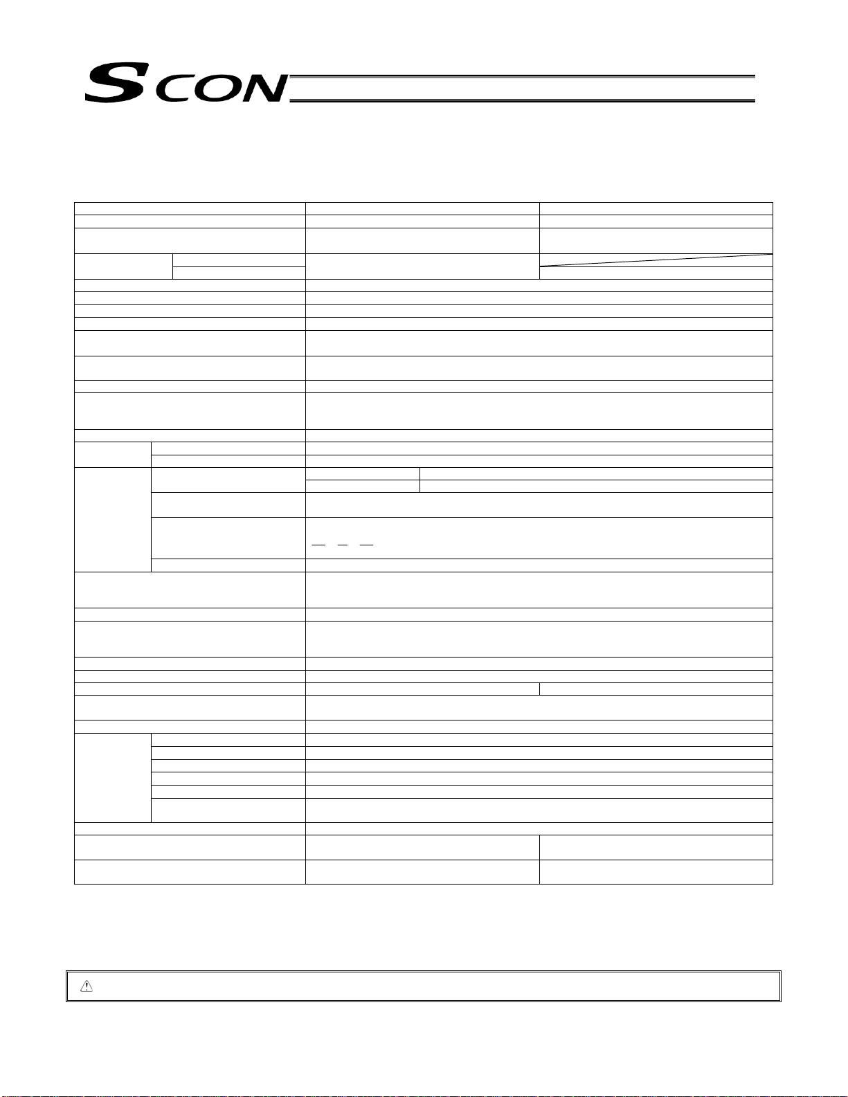
2. Specifications
2.1 Basic Specifications
Item Less than 400 W 400 W or more
Applicable motor capacity 20 W to 399 W 400 W to 750 W
Power-supply voltage
100 VAC Rush current *1
Leak current *2 3.0 mA (Primary side when noise filter is connected to the power supply line)
Heat output 30 W to 58 W
Power supply frequency 50/60 Hz
PIO interface power supply *3
Solenoid brake power supply
(in case of actuators equipped with brake)
Resistance against temp orary electric power
failure
Motor control method Sine wave PWM vector current control
Supported encoders Incremental serial encoder
Operation mode Positioner mode/pulser-train control mode (Operation mode is switched with the DIP switch.)
mode
Pulse-train
mode
Serial communication interface RS485: 1 channel (conforming to Modbus protocol RTU/ASCII)
I/O (PIO) cable length 10 m or less
Communication cable length Total cable length shall be 100 m or less (RS485).
Data input method Teaching pendant, PC software
Protective functions Overvoltage, motor overcurrent, motor overload, driver temperature error, encoder error, etc.
Air cooling method Natural cooling Forced cooling
Withstand voltage Between primary and secondary: 1500 VAC, 1 minute
Insulation resistance
Environment
Protection class IP20
Weight Approximately 800 g (approximately 25 g more
External dimension 58 (W) x 194 (H) x 121 (D)
*1 Rush current flows approximately 20 ms after turning the power supply on (guideline at 40C).
*2 Leak power supply changes depending on the capacity of connected motor, cable length, and surrounding environment. If protection against leak
current is installed, measure leak current at installation location of leak current breaker.
*3 Power supply for I/O signals is not necessary if the controller is operated using field network (CC-Link, DeviceNet, PROFIBUS), gateway unit, or
SIO converter, without using PIO. In this case, set “1” (disabled) for parameter No. 74 (PIO power supply monitoring).
200 VAC
Number of positions 512 points (maximum) Positioner
Inputs/outputs 16 dedicated input points / 16 dedicated output points
Feedback pulse frequency The maximum speed with differential pulse is 500 kpps (up to 109 kpps can be output linearly
Command pulse multiplier
(electronic gear: A/B)
Dedicated I/O (PIO) 8 input points / 12 output points
Surrounding air temperature
Surrounding humidity 85%RH or less (no condensation)
Surrounding environment (See the installation environment section.)
Storage ambient temperature
Storage ambient humidity 90%RH or less (no condensation)
Vibration resistance XYZ directions, 10 to 57 Hz, one side width 0.035 mm (continuous), 0.075 mm (intermittent)
Caution: Position data, parameters, etc. are written in EEPROM. The number of writings is limited to approximately 100,000 times.
Single-phase 100 to 115 VAC 10%
Single-phase 200 to 230 VAC 10%
20 A (control), 70 A (drive)
24 VDC 10% (Externally supplied)
24 VDC 10% 1 A (peak value)
(Externally supplied)
10 ms (50 Hz), 8 ms (60 Hz)
Absolute serial encoder
ABZ (UVW) parallel encoder
Differential pulse MAX. 500 kpps Input pulse frequency
Open-collector pulse MAX. 200 kpps (Pulse converter AK-04 is required.)
following the speed of actuators).
A, B = 1 to 4096 (Parameter settings)
1
50
Speed: 9.6 kpps to 230.4 kpps
Control via serial communication is possible with the positioner mode.
Length in case of Fieldbus specifications (CC-Link, DeviceNet, PROFIBUS) depends on each
Fieldbus specification.
Between primary and FG: 1500 VAC, 1 minute
Between secondary and FG: 500 VDC 100 M or more
0C to 40C
-10C to 65C
in case of absolute specifications)
(Installation pitch: 184)
50
A
1
B
57 to 150 Hz 4.9 m/s2 (continuous), 9.8 m/s2 (ongoing)
Single-phase 200 to 230 VAC 10%
20 A (control), 80 A (drive)
Approximately 1100 g (approximately 25 g more
in case of absolute specifications)
72 (W) x 194 (H) x 121 (D)
(Installation pitch: 184)
9
Page 28
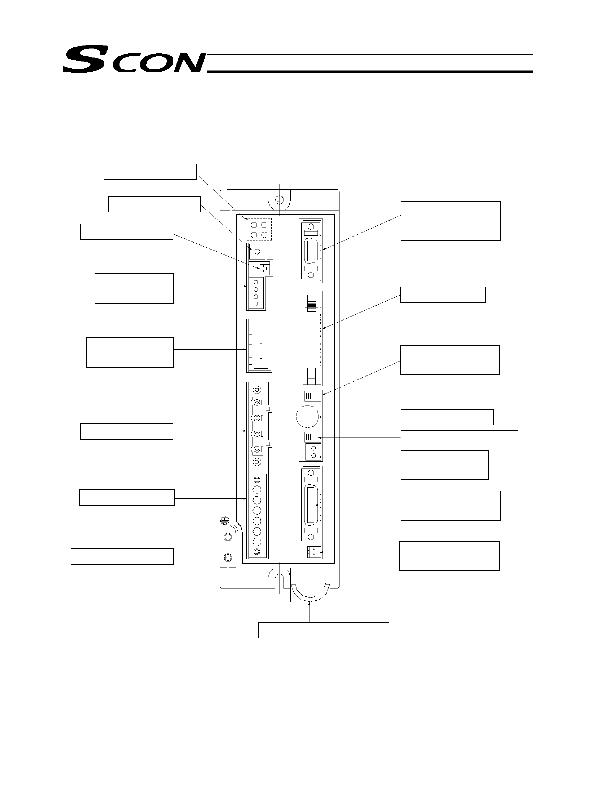
2.2 Name and Function of Each Part
[17] Grounding screw
[1] LED indicators
[2] Rotary switches
[3] Piano switches
[4] System I/O
connector
[5] Regenerative
unit connector
[6] Motor connector
[7] Power connector
[16] Absolute battery holder
[8] Dedicated pulse-
train control
connector
[9] PIO connector
[10] AUTO/MANU
selector switch
[11] SIO connector
[12] Brake release switch
[13] Brake power
connector
[14] Encoder/sensor
connector
[15] Absolute battery
connector
10
Page 29
[1] LED indicators
These LEDs indicate the condition of the controller.
Name Color Description
PWR Green
This LED illuminates when the system has become ready (after the power has
been input and the CPU has started normally).
SV Green This LED illuminates when the servo has turned on.
ALM Orange This LED illuminates while an alarm is present.
EMG Red This LED illuminates while an emergency stop is actuated.
[2] Rotary switches
These switches are used to set the controller address.
If two or more controllers are linked via serial communication, set a unique address for each controller.
* The address set by the switches will become effective after the power is reconnected or software is reset.
[3] Piano switches
These switches are used to set the various modes of the controller system.
Name Description
Operation mode selector switch
1
OFF: Positioner mode, ON: Pulse-train control mode
* The mode set by the switch will become effective after the power is reconnected.
2 Reserved by the system. (This switch must be set to “OFF.”)
Caution: When controlling the SCON controller via serial communication, a lways set the controller in the
“positioner mode” (piano switch 1: OFF).
If it happens to be in the “pulse-train mode” by mistake, the SCON controller may operate
erratically because it is operated according to the “pulse-train mode” parameters.
[4] System I/O connector
This connector is used to connect the emergency stop switch, etc.
Connector (controller side): MC1.5/4-G-3.5 (Phoenix Contact)
Connector (plug-in side): FMC1.5/4-ST-3.5 (Phoenix Contact)
Applicable cable diameter: 0.2 to 1.3 mm
2
(AWG24 to 16)
Pin No. Signal name Description
1 S1 Emergency-stop switch contact output for teaching pendant
2 S2 Emergency-stop switch contact output for teaching pendant
3 EMG+ 24-V output for emergency stop
4 EMG- Emergency sop input
11
Page 30
[5] Regenerative unit connector
This connector is used to connect an external regenerative resistance unit. The need for regenerative unit
will vary depending on the use condition.
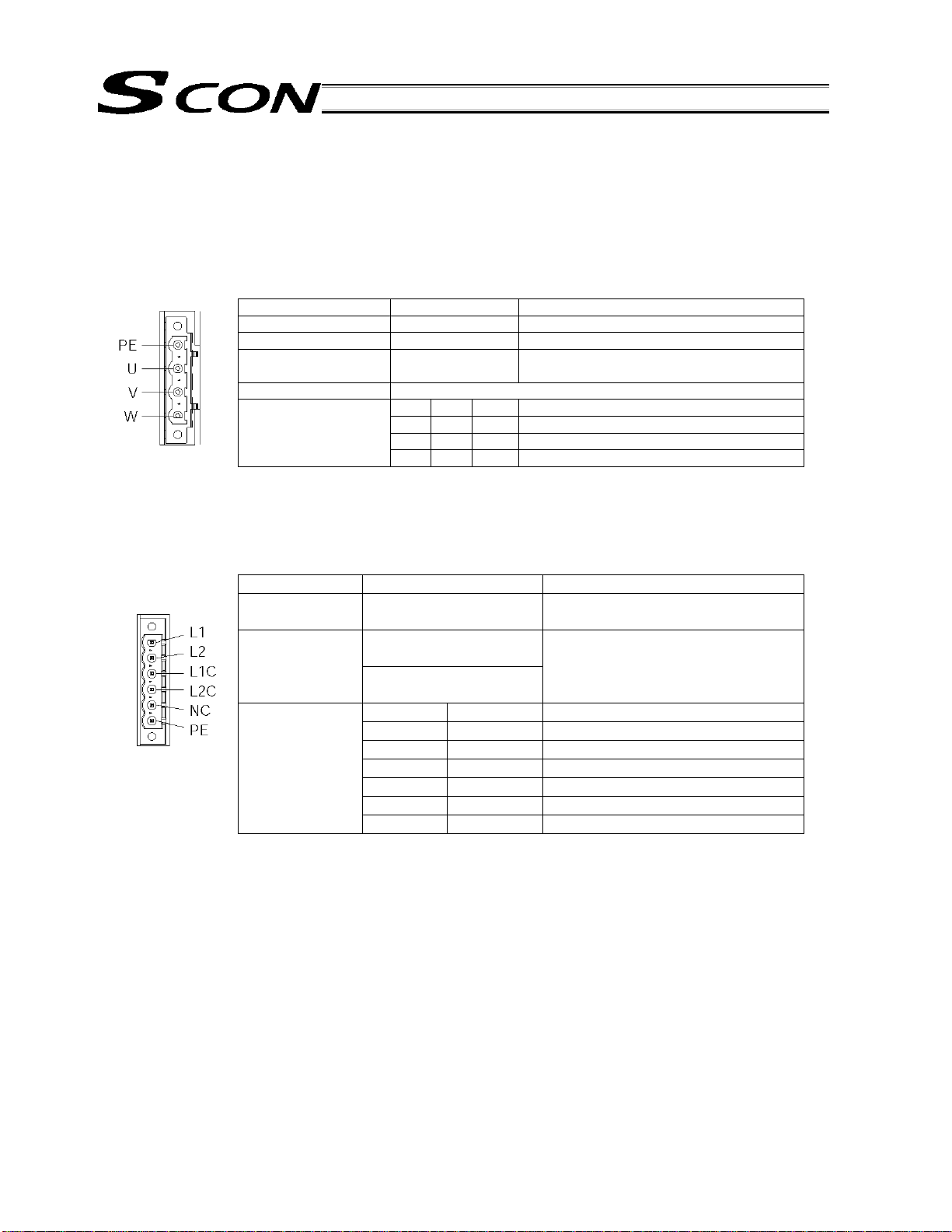
[6] Motor connector
This connector is used to connect the motor power cable of the actuator.
Motor connector specifications
Item Overview Description
Connector (cable side) GIC2.5/4-STF-7.52 4-pin, 2-piece connector by Phoenix Contact
Connector name M1 to 2 Motor connector
Cable size 0.75 mm2 (AWG18
or equivalent)
Connected unit Actuator
Terminal assignments
1 PE Protective grounding wire
2 Out U Motor drive phase U
3 Out V Motor drive phase V
4 Out W Motor drive phase W
Supplied with the actuator
[7] Power connector
This power connector accepts a 100/200-VAC single-phase power supply. The pins a re divid ed into control
power inputs and motor power inputs.
Item Specification Remarks
Connector
(cable side)
Applicable cable
size
6-pin, 2-piece connector MSTB2.5/6-STF-5.08
connector by Phoenix Contact
Control power: 0.75 mm
(AMG18)
Motor power: 2 mm
2
Recommended stripped wire length:
2
7 mm
(AMG14)
Terminal
assignments
Pin No. Signal name
1 L1 Motor power AC input
2 L2 Motor power AC input
3 L1C Control power AC input
4 L2C Control power AC input
5 NC Not connected
6 PE Grounding terminal
Signal names are indicated on the mating connector.
[8] Dedicated pulse-train input mode connector
This connector is used when the controller is to be operated in the pulse-train input mode. Do not conn ect it
if the controller is to be operated in the positioner mode.
[9] PIO connector
This connector is used to connect to the host controller (PLC, etc.) via the PIO (parallel input/output) cable.
It consists of a 40-pin flat connector and constitutes a DIO group of 16 inputs and 16 outputs.
12
Page 31

[10] AUTO/MANU switch
The operating mode using the teaching pendant/PC (software) connected to the SIO connector, and PIO
input, will change as follows in accordance with the setting of this switch.
Prohibition/permission of PIO activation is specified using the PC software/teaching pendant.
MANU
AUTO
PIO activation inhibited
(teaching mode 1 or teaching
mode 2)
PIO activation permitted
(monitor mode 1 or monitor
mode 2)
Only monitoring operations are possible using the PC software/teaching pendant. PIO inputs are
accepted.
All operations are possible using the PC software/teaching pendant.
PIO inputs are not accepted.
Only monitoring operations are possible using the PC
software/teaching pendant. PIO inputs are accepted.
* The emergency stop switch on the teaching pendant is enabled when the switch is co nnected,
regardless of the AUTO/MANU mode. Take note that although an emergency stop is actuated
momentarily when the teaching pendant or SIO cable is removed, this does not indicate an error
condition.
Therefore, the actuator and other equipment that are currently operating will stop.
Do not disconnect the teaching pendant or SIO communication cable while an actuator or any other
equipment is operating.
[11] SIO connector
This connector is used to connect the dedicated communication cable for teaching pendant/PC. It is also
used when two or more controllers are linked via serial communi cation.
[12] Brake release switch
This switch forcibly releases the electromagnetic brake of an actuator with brake.
RLS: Power is supplied to the brake to forcibly release the brake.
NOM: The co ntroller controls ON/OFF of the brake. This setting should be used in normal conditions of use.
* A 24-VDC power supply must be connected to drive the brake.
Even if the controller power is not turned on, you can still move the slider or rod manually by turning on
the 24-VDC power supply for driving the brake and then forcibly releasing the brake.
[13] Brake power connector
This connector supplies the 24-VDC brake powe r. If an actuator with brake is connected, 24 VDC must be
supplied externally.
MC1.5/4-G-3.5
(Phoenix Contact)
* Turn on the 24-VDC brake power before turning on the SCON controller power.
[14] Encoder/sensor connector
This connector is used to connect the encoder/sensor cabl es of the actuator.
With the SCON, encoder voltage is adjusted using a parameter (one of four levels is set in accordance with
the encoder type and cable length).
13
Page 32

A
14
Encoder sensor cable
Cable model: CB-X1-PA ***
Controller end
Plug connector:
Hood:
(Sumitomo 3M)
(Sumitomo 3M)
Wiring diagram
Wire Color Signal
(soldered)
Orange
Green
Purple
Gray
Red
Black
Blue
Yellow
Connect the shield to the hood using
a clamp.
Drain wire and braided shield wire
Plug housing:
Socket contact:
Retainer:
Signal Color Wire
Purple
Gray
Orange
Green
(pressure-
Red
welded)
Black
Drain
Blue
Yellow
(JST)
(JST)
ctuator end
(JST) X 9
Page 33

A
A
Cable model: CB-X1-PLA ***
Controller end
Plug connector:
Hood:
(Sumitomo 3M)
(Sumitomo 3M)
Wiring diagram
Wire Color Signal
White/Blue
White/Yellow
White/Red
White/Black
White/Purple
White/Gray
(soldered)
Orange
Green
Purple
Gray
Red
Black
Blue
Yellow
Connect the shield to the hood using
a clamp.
Drain wire and braided shield wire
ctuator end
LS side
Plug housing:
Socket contact:
Retainer:
Plug housing:
Socket contact:
Retainer:
Signal Color Wire
White/Blue
White/Yellow
White/Red
(pressure-
White/Black
welded)
White/Purple
White/Gray
Signal Color Wire
Purple
Gray
Orange
Green
Red
(pressure-
welded)
Black
Drain
Blue
Yellow
(JST)
(JST)
(JST)
(JST)
LS side
ctuator end
(JST) X 9
(JST) X 6
15
Page 34

A
16
Cable model: CB-X2-PA ***
Controller end
Plug connector:
Hood:
(Sumitomo 3M)
(Sumitomo 3M)
Wiring diagram
Wire Color Signal
(soldered)
White/Blue
White/Yellow
White/Red
White/Black
White/Purple
White/Gray
Orange
Green
Purple
Gray
Red
Black
Blue
Yellow
Connect the shield to the hood
using a clamp.
Drain wire and braided shield wire
Plug housing:
Socket contact:
Retainer:
Color Wire
Signal
White/Blue
White/Yellow
White/Red
White/Black
White/Purple
White/Gray
Drain
Orange
Green
Purple
Gray
Red
Black
Blue
Yellow
(JST) X 2
(pressure-
welded)
(JST)
ctuator
end
(JST) X 15
Page 35

A
A
Cable model: CB-X2-PLA ***
Controller end
17
Plug connector:
Hood:
(Sumitomo 3M)
(Sumitomo 3M)
Wiring diagram
Wire Color Signal
White/Orange
White/Green
Brown/Blue
Brown/Yellow
Brown/Red
Brown/Black
White/Blue
White/Yellow
White/Red
White/Black
White/Purple
White/Gray
Orange
Green
Purple
Gray
Red
Black
Blue
Yellow
(soldered)
Connect the shield to the hood using
a clamp.
Ground wire and braided shield wire
ctuator end
LS side
Plug housing:
Socket contact:
Retainer:
Plug housing:
Socket contact:
Retainer:
Signal Color Wire
White/Orange
White/Green
Brown/Blue
Brown/Yellow
Brown/Red
Brown/Black
Signal Color Wire
White/Blue
White/Yellow
White/Red
White/Black
White/Purple
White/Gray
Drain
Orange
Green
Purple
Gray
Red
Black
Blue
Yellow
(JST) X 2
(JST)
(pressure-
welded)
(pressure-
welded)
(JST)
(JST)
LS
side
ctuator
end
(JST) X 15
(JST) X 6
Page 36

A
18
Cable model: CB-RCS2-PA ***
Controller end
Plug connector:
Hood:
(Sumitomo 3M)
(Sumitomo 3M)
Wiring diagram
Wire Color Signal
(soldered)
Connect the shield to the hood using
a clamp.
White/Green
Brown/White
Pink
Purple
White
Blue/Red
Orange/White
Green/White
Blue
Orange
Black
Yellow
Green
Brown
Gray
Red
Drain wire and braided shield wire
Plug housing:
Socket contact:
Retainer:
Signal Color Wire
Pink
Purple
White
Blue/Red
Orange/White
Green/White
Brown/White
Drain
Blue
Orange
Black
Yellow
Green
Brown
Gray/White
Gray
Red
(JST) X 2
(pressure-
welded)
(JST)
ctuator
end
(JST) X 17
Page 37

A
A
Cable model: CB-RCS2-PLA ***
Controller end
19
Plug connector:
Hood:
(Sumitomo 3M)
(Sumitomo 3M)
Wiring diagram
Wire Color Signal
Brown/White
Gray/White
Red/White
Black/White
Yellow/Black
Pink/Black
Pink
Purple
(soldered)
Connect the shield to the hood using
a clamp.
White
Blue/Red
Orange/White
Green/White
Blue
Orange
Black
Yellow
Green
Brown
Gray
Red
Drain wire and braided shield wire
ctuator end
LS side
Plug housing:
Socket contact:
Retainer:
Plug housing:
Socket contact:
Retainer:
Color Wire
Signal
BrownWhite
Gray/White
Red/White
(pressure-
welded)
Black/White
Yellow/Black
Pnk/Black
Signal Color Wire
Pink
Purple
White
Blue/Red
Orange/White
Green/White
(pressure-
welded)
Drain
Blue
Orange
Black
Yellow
Green
Brown
Gray
Red
(JST) X 2
(JST)
(JST)
(JST)
LS side
ctuator end
(JST) X 15
(JST) X 6
Page 38

[15] Absolute battery connector
This connector is used to connect the absolute-encoder backup battery (required when the controller is of
absolute encoder specification).
[16] Absolute battery holder
This battery holder is used to install the absolute-encoder backup battery.
[17] Grounding screw
This screw is used to implement protective grounding. It is connected inside the controlle r to the PE
terminal in the power connector. Use this terminal if protective grounding based on a 2-piece connector is
not feasible due to conflict with the safety standard or for any other reason.
Item Description
Cable size 2.0 to 5.5 mm2 or larger
Grounding method Class D grounding
20
Page 39

2.3 External Dimensions
External dimensions of models with a power output of less than 400 W
4.2
When the absolute battery is installed
(absolute encoder specification)
21
Page 40

External dimensions of models with a power output of 400 W or more
4.2
When the absolute battery is installed
(absolute encoder specification)
Fan
22
Page 41

3. Installation and Wiring
3.1 Installation Environment
(1) When installing and wiring the controller, do not block the ventilation holes for cooling. (Insufficient
ventilation may not only prevent the controller from demonstrating its design performance fully, but it may
also cause a breakdown.)
(2) Prevent foreign matter from entering the controller through the ventilation holes. This controller is not
dustproof or splashproof (against water or oil), so avoid using the controller in a place subject to large
amounts of dust, oil mist or splashes of cutting fluid.
(3) Keep the controller from direct sunlight or irradiated heat from large heat sources such as heat treatment
furnaces.
(4) Use the controller in an environment of 0 to 40C in surrounding air temperature and 85% or below in
humidity (non-condensing), where the surrounding air is free fro m corrosive or flammable gases.
(5) Use the controller in an environment where it does not receive external vibration or impact.
(6) Prevent electrical noise from entering the controller or connected cables.
3.2 Heat Radiation and Installation
Design the control panel size, controller layout and cooling method so that the temperatures around the
controller will always be kept to 40C or below.
Mount the controller on a wall vertically as shown below. This controller implements cooling by means of f orced
ventilation (air is blown out from the top). When installing the controller, observe the aforementioned direction
and provide a minimum clearance of 100 mm above and 50 mm below the controller, and 30 mm from an
adjacent controller.
If you are installing multiple controllers side by side, provide a fan on top of the controllers to agitate the
airflows as an effective way to keep the surrounding air temperatures constant.
Provide a minimum clearance of 150 mm between the front face of the controller and the wall (cover).
Regenerative boxes
If multiple controllers are linked with the controllers arranged vertically, make sure the exhaust air from a given
controller is not sucked into the controller above it.
Provide a clearance of approx. 50 mm between a controller and a regenerative b ox, or 10 mm between
regenerative boxes.
Air direction
Fan
At least 100 mm
At least 50 mm
At least
150 mm
Airflow
23
Page 42

3.3 Noise Elimination Measures and Grounding
The following explains the noise elimination measures that should be taken when using this co ntroller.
(1) Wiring and power connection
[1] Provide dedicated class-D grounding (former class-3 grou nding: Grounding resistance 100 or less) using
a grounding wire with a size of 1.6 mm
Controller
Attach the
grounding
wire to the
mounting
screw of the
main unit.
Connect a cable of
the largest possible
size over the shortest
possible distance
Grounding terminal Grounding terminal
equip-
Class-D grounding
(Former class-3 grounding:
Grounding resistance 100 or less)
[2] Cautions on wiring method
Separate the controller wiring from high-power lines of motive power circuits, etc. (Do not tie them together
or place in the same cable duct.)
If the supplied motor or encoder cable is to be extended, consult IAI’s Engineering Service Section or Sales
Engineering Section.
(2) Noise sources and elimination
Noise generates from many sources, but the most common sources of noise you should consider when
designing a system are solenoid valves, magnet switches and relays. Noise generation from these components
can be prevented by the method explained below.
[1] AC solenoid valves, magnet switches, relays
Method --- Mount a noise killer in parallel with the coil.
Other
ment
2
or larger.
Controller
Ground the grounding wire for each controller:
do not share with or connect to other equipment.
Other
equip-
ment
Noise killer
Connect to each coil over the shortest possible wiring distance.
When a surge absorber is installed on the terminal block, etc., its
noise elimination effect will decrease if the distance from the coil
is long.
24
Page 43

[2] DC solenoid valve/magnet switch relay
Action --- Install a diode in parallel with the coil or use valve/relay with built-in diode.
In a DC circuit, connecting a diode in reverse polarities may damage the
diode, internal controller parts, or DC power supply. Exercise due caution
when connecting a diode.
25
Page 44

3.4 Wiring the Power Supply
3.4.1 Connecting the Power Cable
As shown to the left, insert the stripped end of the cable into the
connector and screw in the cable using a screwdriver.
Recommended cable diameter
Motor power (L1, L2): 2 mm (AWG14)
Control power (L1C, L2C): 0.75 mm (AWG18)
Recommended stripped wire length: 7 mm
As shown to the left, tighten the screws to secure the connector.
Caution: Always install a noise filter.
Recommended noise filter: MC1210 by Densei-Lambda
The power-supply voltage of the controller (100 or 200 V) has been set prior to the shipment.
26
Page 45

3.4.2 Power-supply Capacities and Heat Output
Rated power-supply capacity = Motor power-supply capacity + Control power-supply capacity
Maximum momentary power-supply capacity = Maximum momentary motor power-supply capacity + Control
power-supply capacity
Actuator motor
wattage
Motor power-
supply capacity
[VA]
Maximum
momentary motor
power-supply
capacity [VA]
Control power-
supply capacity
[VA]
Rated power-
supply capacity
[VA]
Maximum
momentary power-
supply capacity
[VA]
Heat
output
[W]
(Excluding RS)
(Excluding RS)
RS: Rotational axis
200L: 200-W linear actuator
300L: 300-W linear actuator
400L: 400-W linear actuator
3.4.3 Selecting a Breaker
Follow the guidance below when selecting a breaker.
Current 3 times more than the rated current flows in the controller during acceleration/deceleration. Select a
breaker that does not trip when this current is conducted. If a trip occurs, select a breaker with rated current
one rank higher.
Select a breaker that does not trip due to rush current. (Refer to operation characteristic curves described in
catalogues by manufacturers.)
Select a breaker with rated breaking current values that can break without fails even if short-circuit current is
conducted.
Rated breaking current > short-circuit current = primary side power supply capacity / power supply voltage
Select a circuit breaker with rated current with sufficient margin.
Rated breaker current > (Rated motor power-supply capacity [VA] + Control power-sup ply capacity
[VA]) / AC input voltage
Moreover, leak current breakers must be selected with specific purposes such as protection again st fire,
protection of humans and so on. Furthermore, leak current shall be measured at the location where a leak
current breaker is installed. Please use a leak current breaker supporting higher harm onics.
27
Page 46

3.5 Connecting the Actuator
3.5.1 Connecting the Motor Cable (MOT1, 2)
Connect the motor cable of the actuator to the motor connector on
the front face of the controller.
Use a screwdriver to tighten the screws at the top and bottom of the
connector to secure the connector.
2.
3.5.2 Connecting the Encoder Cable (PG1, PG2)
28
Connect the encoder cable of the actuator to the encoder connector
on the front face of the controller.
Note) If the controller is of absolute specification, disconnect the
absolute battery connector before connecting the encoder
cable.
Page 47

3.6 Connecting the PIO Cable (I/O)
Connect the supplied flat cable. Connect the opposite end of the
cable (no connector) to an appropriate peripheral (host PLC, etc.).
Brown-1
Red-1
Orange-1
Yellow-1
Green-1
Blue-1
Purple-1
Gray-1
White-1
Black-1
Brown-2
Red-2
Orange-2
Yellow-2
Green-2
Blue-2
Purple-2
Gray-2
White-2
Black-2
Half-pitch MIL socket: HIF6-40D-1.27R
(Hirose)
Signal Color Wire
Flat cable
[A]
(pressure-
welded)
I/O flat cable (supplied) Model: CB-PAC-PIO
indicates the cable length (L). A cable length of up to 30 m is supported.
*
Example: 080 = 8 m
Flat cable: KFX-20 (S) (color) (Kaneko Cord)
No connector
No connector
Flat cable (20 cores) x 2
Signal Color Wire
Brown-3
Red-3
Orange-3
Yellow-3
Green-3
Blue-3
Purple-3
Gray-3
White-3
Black-3
Brown-4
Red-4
Orange-4
Yellow-4
Green-4
Blue-4
Purple-4
Gray-4
White-4
Black-4
Flat cable
[B]
(pressure-
welded)
29
Page 48

3.7 External Input/Output Specifications
The standard interface specification of the controller is NPN, but the PNP specification is also available as an
option.
To prevent confusion during wiring, the NPN and PNP specifications use the same power line configuration.
Accordingly, there is no need to reverse the power signal assignments for a PNP controller.
3.7.1 External Input Specifications
Item Specification
Number of input points 16 points
Input voltage
Input current 4 mA/point
Insulation method Photocoupler
Internal circuit configuration
[NPN specification]
Each input
Each input
[PNP specification]
Each input
Each input
24 VDC 10%
ON voltage: Min. 18 VDC (3.5 mA) ON/OFF voltage
OFF voltage: Max. 6 VDC (1 mA)
Logic
circuit
Logic
circuit
Internal
circuit
Internal
circuit
30
Page 49

3.7.2 External Output Specifications
Item Specification
Number of output points 16 points
Rated load voltage 24 VDC
Maximum current 100 mA/point 400 mA/8 points
Insulation method Photocoupler
Internal circuit configuration
[NPN specification]
[PNP specification]
Internal
circuit
Internal
circuit
Logic
circuit
Logic
circuit
Load
Each output
Load
Each output
Load
Each output
Load
Each output
31
Page 50

3.8 Connecting the Emergency Stop Input (Wiring to the System I/O
Connector)
As shown to the left, insert the stripped end of the cable while
pressing down the spring using a screwdriver.
Applicable cable diameter: 0.2 to 1.3 mm (AWG24 to 16)
Recommended stripped wire length: 10 mm
Emergency stop switch
32
Page 51

Emergency stop circuit when multiple controllers are linked
Internal drive-source cutoff specification (Connections when the entire system requires a level of safety conforming to safety category B)
Connect an emergency-stop status relay contact for each controller. Make sure to install a surge-absorbing element for the external relay.
S1, S2 contact specification: 30 VDC/0.5 A
SIO
connector
EMG line control relay
TP connected: Open
TP not connected:
Closed
SIO
connector
EMG line control relay
TP connected: Open
TP not connected:
Closed
SIO
connector
EMG line control relay
TP connected: Open
TP not connected:
Closed
External CMG
reset
switch
External CMG
switch
System I/O
connector
System I/O
connector
System I/O
connector
Power
connector
Motor power
Power
connector
Power
Motor power Motor power
connector
33
Caution: When the teaching pendant is disconnected, an emergency stop is actuated momentarily. The emergency stop will be cancelled
immediately thereafter, but the actuator and other equipment that are operating when the teaching pendant is disconnected will stop.
Therefore, do not disconnect the teaching pendant when an actuator or any other equipment is operating.
Also pay attention to the design of the emergency stop circuit that includes the emergency stop switch on the teaching pendant.
Page 52

34
Page 53

On Support of Safety Categories
[1] System configuration
When constructing a system supporting safety categories, use teaching pendant “CON-TG" and TP adapter
“RCB-LB-TG."
It is possible to support categories from B to 4 by changing connection of the system I/O connector.
Controller/
TP adapter
connection cable
model:
CB-CON-LB005
Controller
connector
TP adapter "RCB-LB-TG"
Dummy plug “DP-4”
Teaching pendant “CON-TG”
(or dummy plug “DP-4”)
System I/O connector
(The front (ENB*) is the
lower side and the back
(EMG*) is upper side.)
Safety circuit connection
Teaching pendant
connector
35
Page 54

[2] Wiring and setting of safety circuit
[1] Power supply
If a safety circuit is configured using safety relays and contactors of 24 V specifications, it is recommended to
use a separate power supply from the power supply for controllers of 24 V specifications (A CON, PCON etc.).
It can be configured using the common power supply between the two, but breakage may occur when falsely
wired.
[2] System I/O connector specification
Connector used: MCDN1.5/6-G1-3.5P26THR (PHOENIX CONTACT)
Cable side connector (accessory: initial wiring already conducted *):
FMC1.5/6-ST-3.5 (PHOENIX CONTACT)
Supported wire thickness: AWG24-16, recommended stripped wire length: 7 mm
Pin No. Signal name Explanation
Upper side
(EMG side)
1 EMG12 EMG1+
3 EMG24 EMG2+
Emergency stop contact 1
(30 VDC or less, 100 mA or less)
Emergency stop contact 2
(30 VDC or less, 100 mA or less)
5 EMGIN Emergency stop detection input
6 EMGOUT 24 V power supply output for emergency stop detection input
Lower side
(ENB side)
7 ENB18 ENB1+
9 ENB2-
10 ENB2+
Enable contact 1
(30 VDC or less, 100 mA or less)
Enable contact 2
(30 VDC or less, 100 mA or less)
11 ENBIN Enable detection input
12 ENBOUT 24 V powe r supply output for enable detection input
* Connectors on the cable side are attached under conditions where initial wiring has been conducted.
In order to support each category, remove the initial wiring and wire your safety circuit.
Upper side (EMG) connector Lower side (ENB) connector
Wiring Color Signal
Yellow
Yellow
Yellow
Yellow
Wiring Color Signal
Yellow
Yellow
Yellow
Yellow
36
Page 55

[3] Connection of dummy plug
If you operate a controller in the AUTO mode, connect a dummy plug (DP-4) to the TP connector.
* Make sure to use “DP-4" as the dummy plug. If “DP-3” is used, the connector does not operate normally.
[4] Enable function
If you are using the enable function, set it to Enable using the controller parameter.
Parameter No. 42 Enable function
0: Enable
1: Disable [Default setting at shipment]
37
Page 56

[3] Examples of safety circuits
[1] In case of category 1
Controller
Connection cable CB-CON-LB***
Motor
power
supply
(or dummy plug: DP-4)
stop
switch
Emergency
Reset
switch
Enable switch
Solenoid contactor
Motor power supply
38
Page 57

Detailed category 1 circuit example
Connect with
dedicated cable
At TP detection
T24V: Output
Bypass relay: OPEN
At TP not detected
T24V: Not output
Bypass relay: CLOSE
TP connection
detection
DC bus
Motor power
cutoff relay
Regulator
Controller
connector
Shell
System I/O
connector
TP adapter
stop
switch
Emergency
Reset
switch
External emergency
stop circuit category 1
Enable switch
Solenoid contactor
TP connector
Emergency stop
Enable switch
Shell
switch
39
Page 58

[2] In case of category 2
Controller
Motor
power
supply
Connection cable CB-CON-LB***
Emergency stop switch
Enable switch
Reset switch
Solenoid contactor
(or dummy plug: DP-4)
Solenoid contactor
Motor power supply
40
Page 59

Detailed category 2 circuit example
Connect with
dedicated cable
At TP detection
T24V: Output
Bypass relay: OPEN
At TP not detected
T24V: Not output
Bypass relay: CLOSE
TP connection
detection
DC bus
Motor power
cutoff relay
Regulator
Controller
connector
Shell
System I/O
connector
Emergency stop switch
TP adapter
External emergency
stop circuit category 2
TP connector
Enable switch
Reset switch
Solenoid contactor Solenoid contactor
Emergency stop
switch
Enable switch
Shell
System I/O connector
(Safety unit connection)
41
Page 60

[3] In case of category 3 or 4
Controller
Connection cable CB-CON-LB***
Emergency stop switch
Motor
power
supply
Enable switch
Reset switch
Solenoid contactor
(or dummy plug: DP-4)
Short circuit reset switch
if category 3 should be
supported
Solenoid contactor
Short circuit only
when category 3
should be supported
Motor power supply
42
Page 61

Detailed category 3/4 circuit example
Connect with
dedicated cable
Controller
connector
At TP detection
T24V: Output
Bypass relay: OPEN
At TP not detected
T24V: Not output
Bypass relay: CLOSE
TP connection
detection
System I/O
connector
DC bus
Motor power
cutoff relay
Regulator
TP adapter
Shell
Emergency stop switch
External emergency
stop circuit category 4
TP connector
Enable switch
Reset switch
Solenoid contactor Solenoid contactor
Emergency stop
switch
Enable switch
Shell
System I/O connector
(Safety unit connection)
Short circuit reset switch
if category 3 should be
supported
Short circuit only
when category 3
should be
supported
43
Page 62

[4] Appendix
[1] TP adapter external dimensions
2-3.5
[2] Connection cable
Controller/TP adapter connection cable
Use this cable to connect the controller and TP adapter (RCB-LB-TG).
Model: CB-CON-LB005 (standard cable length: 0.5 m)
Maximum cable length: 2.0 m
Color
8-pin MIN DIN connector (mold casting)
Contact: MD-SP2240 (JST) x 8
Metal shell: MD-PS8T (JST)
Housing A: MD-PI8A (JST)
Housing B: MD-PI8B (JST)
Cover: MD-PCC8T (JST)
Signal
Brown
Yellow
Red
Orange
Blue
Green
Purple
Gray
Shield
8-pin MIN DIN connector (mold casting)
Color
Signal
Brown
Yellow
Red
Orange
Blue
Green
Purple
Gray
Shield
Contact: MD-SP2240 (JST) x 8
Metal shell: MD-PS8T (JST)
Housing A: MD-PI8A (JST)
Housing B: MD-PI8B (JST)
Cover: MD-PCC8T (JST)
44
Page 63

[3] Dummy plug
Connect a dummy plug to the teaching pendant connecting connector.
Make sure to connect a dummy plug if the AUTO mode is specified.
Model: DP-4
Signal
Plug
Short-circuit processing
45
Page 64

Connecting the Pulse-train Control Cable
Use the pulse-train control cable when the controller is operated in
the pulse-train input mode. It should not be connected when the
controller is operated in the positioner mode.
The pulse-train control cable is optional. (Normally the controller
comes only with a plug and a shell.)
Connecting the Brake Power Input (for Actuator with Brake)
As shown to the left, insert the stripped end of the cable into the
connector and screw in the cable using a screwdriver.
Applicable cable: 0.75 to 1.25 mm
Recommended stripped wire length: 7 mm
24 VDC 10%,
1 A max.
46
Page 65

Connecting the Teaching Pendant/PC Software (TP) (Optional)
If the teaching pendant/PC software cable is used, connect it to the
teaching connector on the controller.
Set the AUTO/MANU selector switch to the MANU position (right
side).
Caution: When the teaching pendant is disconnected, an emergency stop is actuated momentarily. The
emergency stop will be cancelled immediately thereafter, but the actuator and other equipment that
are operating when the teaching pendant is disconnected will stop.
Therefore, do not disconnect the teaching pendant when an actuator or any other equipment is
operating.
Also pay attention to the design of the emergency stop circuit that includes the emergency stop
switch on the teaching pendant.
47
Page 66

3.9 Connecting the Regenerative Unit (RB)
Regenerative energy produced when the actuator decelerate s to a stop or moves downward in vertical
installation is absorbed by means of the capacitor or resistor provided in the controller. If the produced
regenerative energy cannot be fully absorbed by the controller, an overheat error (error code: 0CA) will generate.
If this is the case, connect one or more regenerative resistance units externally.
3.9.1 Number of Units to Be Connected
Guideline for number of units to be connected
Motor wattage
Horizontal installation Vertical installation
~ 100 W ~ 100 W Not required
~ 400 W, 200 S, 300 S ~ 400 W, 200 S, 300 S 1
~ 750 W ~ 750 W 2
* The above are reference values when the actuator is moved back and forth at an operation duty of 50%
based on the rated acceleration/deceleration, rated load and 1000-mm stroke.
* If the operating duty exceeds 50%, the applicable number of regenerative units shown in the table above
must be increased.
The maximum number of external regenerative resistance units that can be connected is as follows:
Less than 400 W --- 2 units
400 W or more --- 4 units
(Never connect external regenerative resistance units more than the limits shown above, as it may result in
system failures.)
3.9.2 Connection Method
Number of regenerative resistance
units to be connected
The figure below illustrates how one regenerative unit, and multiple units, should be connected, respectively.
When connecting one regenerative unit, connect the unit using cable [1] explained in 3.9.3. When connecting
two or more regenerative units, connect the controller with the first regenerative unit using cable [1], and connect
the adjacent regenerative units using cable [2].
[1]
[1]
[2] [2]
48
Page 67

3.9.3 Connection Cables
The cable used to connect the controller to a regenerative resistance unit is different from the corresponding
cable used on conventional controllers (the connectors are not compatible). To conne ct a reg enerative
resistance unit to the controller, cable [1] specified below is required.
[1] Regenerative resistance connection ca ble for SCON (CB-SC-REU***)
Controller end
Receptacle housing:
Receptacle contact:
Sales model nameplate
Wiring diagram
Wire Color Signal
Light blue
Brown
Green/Yellow
Signal Color
[2] Regenerative resistance connection ca ble for co nventional controllers (X-SEL, E-Con) (CB-ST-REU***)
Controller end
Plug:
(Phoenix Contact)
Sales model nameplate
Wiring diagram
Plug:
(Phoenix Contact)
Wire Color Signal
Light blue
Brown
Green/Yellow
Signal
External regenerative
resistance unit end
Plug:
(Phoenix Contact)
Wire
Light blue
Brown
Green/Yellow
External regenerative
resistance unit end
Color Wire
Light blue
Brown
Green/Yellow
49
Page 68

3.10 Connecting the Brake Box (RCB-110-RA13-0)
One brake box can support 2 actuators.
3.10.1 Installation Standard
Actuator to be used: RCS2-RA13R with brake
3.10.2 Specification
Item Specification
Dimension of main unit 162 x 94 x 65.5 mm
Power supply voltage, current
Connection cable (sold separately)
3.10.3 External Dimensions
24 VDC 10% 1 A
Encoder cable (model specification CB-RCS2-PLA
indicates cable length
), where
Encoder
connector 1
4-5
Connector 1 for
brake release
external switch
Power
supply
input
connector
POWER ON LED
(Lit in green when power is supplied)
Encoder
connector 2
Connector 2 for
brake release
external switch
50
Page 69

3.10.4 24 V Power Supply Connector
Connector on
cable side
Conforming cable AWG28 to 16
Terminal assignment
* It is necessary to supply +24 V to the brake power supply connector of the controller as well.
1 0 V Power supply ground for brake excitation
2 24 VIN +24 V power supply for brake excitation
MC1.5 / 2-STF-3.5 (Phoenix Contact)
3.10.5 Brake Release External Switch Connectors 1 and 2
Connection
destination device
Connector on
cable side
Switch rating 30 VDC, minimum current 1.5 mA
Terminal assignment
* If the connector pins 1 and 2 are short circuited, the brake is forcefully released.
1 BKMRL Brake release switch input
2 COM Brake release switch input power supply output
Break release switch
XAP-02V-1
(Contact BXA-001T-P0.6) (JST)
3.10.6 Connection
Input +24 V power supply to the 24 V power supply connector of the external brake connection box.
Controller connection diagram
Motor cable
Encoder cable
Encoder cable
Actuator
SCON 400 W or higher
External brake connection box
51
Page 70

Chapter 2 Positioner Mode
1. I/O Signal Control and Signal Functions
1.1 PIO Patterns and Signal Assignments
This controller provides six PIO pattern types to meet the needs of various applications.
To select a desired type, set a corresponding value from 0 to 5 in parameter No. 25 (PIO pattern selection).
The features of each PIO pattern are explained below:
Parameter No.
25 setting
0
1
2
3
4
5
Positioning mode [Standard type]
A basic type supporting 64 positioning points and two zone outputs.
* How to set zone boundaries within which to output a zone signal:
Zone boundaries are set using parameter Nos. 1 and 2 for one zon e output, and in the position
table for another zone output.
Teaching mode [Teaching type]
In this type, 64 positioning points and one zone output (boundaries are set in the position table)
are supported.
In addition to the normal positioning mode, the user can also select the teaching mode in which
the actuator can be jogged via I/Os and the current actuator position can be written to a
specified position.
(Note) Positions can be rewritten by approximately 100,000 times.
256-point mode [256-point type]
The number of positioning points is increased to 256, so only one zone output is available
(boundaries are set in the position table).
512-point mode [512-point type]
The number of positioning points is increased to 512, so no zone output is available.
Solenoid valve mode 1 [7-point type]
The number of positioning points is limited to seven, but separate direct command inputs and
position complete outputs are provided.
PLC ladder sequence circuits can be designed easily.
Solenoid valve mode 2 [3-point type]
Use of the controller as an air cylinder is assumed in this type.
The function of position complete output signals is different from how these signals function in
the 7-point type. These signals not only indicate that the position specified by each move
command “has been reached,” but the also function as a limit switch. This means that the
signals will turn ON even when the actuator is moved by hand.
Take note that incremental positioning commands are not supported in this mode.
Feature of PIO pattern
52
Page 71

Quick reference table for functions available under each PIO pattern (
Zone output
No. 25
Number of
positioning points
Boundaries set by
parameters
(ZONE1)
0 64 points
1 64 points x
2 256 points x
Zone output
Boundaries set in
the position table
(PZONE)
3 512 points x x
4 7 points
5 3 points
: Available, x: Not available)
Brake release
input signal
(BKRL)
Moving output
signal (MOVE)
x
x
x
x
x
53
Page 72

1.1.1 Explanation of Signal Names
The following explains the signal names, and gives a function overview of each signal.
In the explanation of operation timings provided in a later section, each signal is referenced by its selfexplanatory name for clarity. If necessary, however, such as when marker tubes are inserted as a termination of
the flat cable, use the signal abbreviations.
PIO pattern = 0 Positioning mode [Standard type]
Category Signal name
Command position
number
Brake release BKRL
Input
Output
Operating mode RMDO
Home return HOME Home return operation is started at a rise edge of this signal.
Pause *STP ON: Actuator can be moved, OFF: Actuator decelerates to a stop
Start CSTR The actuator will start moving at a rise edge of this signal.
Alarm reset RES An alarm is reset at a rise edge of this signal.
Servo ON SON
Completed position
number
Moving MOVE
Zone 1 ZONE1
Position zone PZONE
Operating mode status RMDS A signal indicating the operating mode of AUTO or MANU is output.
Home return completion HEND
Position complete PEND
Servo-on status SV
Emergency stop status *EMGS
Alarm *ALM
Battery alarm *BALM
Signal
abbreviation
PC1
PC2
PC4
PC8
PC16
PC32
PM1
PM2
PM4
PM8
PM16
PM32
Function overview
The target position number is input.
A command position number must be specified by 6 ms before the
start signal (CSTR) turns ON.
This signal is used on an actuator equipped with a brake to forcibly
release the brake.
This signal switches the operating mode between AUTO and MANU.
(ON: MANU, OFF: AUTO)
The servo remains ON while this signal is ON.
The servo remains OFF while this signal is OFF.
The relevant position number is output when positioning has
completed.
The signal will turn OFF when the next start signal is received.
It is used by the PLC to check if the commanded position has
definitively been reached, and also to provide a position interlock, etc.
This signal will remain ON while the actuator is moving, and OFF
while the actuator is standing still.
Used to check the operation or determine if the load was missed in
push & hold operation.
This signal becomes effective after home return. It will turn ON when
the current actuator position enters the range set by the parameters
and remain ON until the actuator exits the range.
This signal becomes effective after a position movement command is
input. It will turn ON when the current actuator position enters the
range specified in the position table and remain ON until the actuator
exits the range.
This signal is OFF immediately after the power is input, and turns ON
when home return has completed.
This signal turns ON when the actuator has moved to the target
position and entered the positioning band. It is used to determine if
the positioning has completed.
This signal is always output once the servo is turned ON and the
controller is ready to operate.
When this signal is OFF, it means that an emergency stop is being
actuated.
This signal remains ON in normal conditions of use and turns OFF
when an alarm generates.
This signal is ON when the absolute battery voltage is normal or an
incremental encoder is used.
54
Page 73

PIO pattern = 1 Teaching mode [Teaching type]
Category Signal name
Command position
number
Operation mode MODE Mode selection (ON: Teaching mode, OFF: Normal mode)
Jog/inching switching JISL OFF: Jog, ON: Inching
+jog/inching movement JOG+
Input
-jog/inching movement JOG-
Operating mode RMOD
Home return HOME
Pause *STP
Start CSTR
Current-position write PWRT
Alarm reset RES
Servo ON SON
Completed position
number
Moving MOVE
Mode status MODES
Position zone PZONE
Output
Operating mode status RMDS
Home return completion HEND
Position complete PEND
Write completion WEND
Servo-on status SV
Emergency stop status *EMGS
Alarm *ALM
Battery alarm *BALM
Signal
abbreviation
PC1
PC2
PC4
PC8
PC16
PC32
PM1
PM2
PM4
PM8
PM16
PM32
The target position number is input.
A command position number must be specified by 6 ms before the
start signal (CSTR) turns ON.
The actuator will start jogging or inching in the positive direction at an
ON edge of this signal.
The actuator will start jogging or inching in the negative direction at an
ON edge of this signal.
This signal switches the operating mode between AUTO and
MANU.
Home return operation is started at a rise edge of this signal.
ON: Actuator can be moved, OFF: Actuator decelerates to a stop
The actuator will start moving at a rise edge of this signal.
When this signal has remained ON for 20 msec or longer, the current
position will be stored under the position number selected by PC1 to
PC32.
An alarm is reset at a rise edge of this signal.
The servo remains ON while this signal is ON.
The servo remains OFF while this signal is OFF.
The relevant position number is output when positioning has
completed.
The signal will turn OFF when the next start signal is received.
It is used by the PLC to check if the commanded position has
definitively been reached, and also to provide a position interlock, etc.
This signal will remain ON while the actuator is moving, and OFF
while the actuator is standing still.
Used to check the operation or determine if the load was missed in
push & hold operation.
This signal is ON when the controller is in the teaching mode, and
OFF when the controller is in the normal mode.
This signal becomes effective after a position movement command is
input. It will turn ON when the current actuator position enters the
range specified in the position table and remain ON until the actuator
exits the range.
A signal indicating the operating mode of AUTO or MANU is output.
This signal is OFF immediately after the power is input, and turns ON
when home return has completed.
This signal turns ON when the actuator has moved to the target
position and entered the positioning band. It is used to determine if
the positioning has completed.
This signal is output upon completion of writing to the nonvolatile
memory in response to a current-position write command (PWRT).
This signal is always output once the servo is turned ON and the
controller is ready to operate.
OFF: Emergency stop has been actuated
This signal remains ON in normal conditions of use and turns OFF
when an alarm generates.
This signal is ON when the absolute battery voltage is normal or an
incremental encoder is used.
Function overview
(ON: MANU, OFF: AUTO)
55
Page 74

PIO pattern = 2 256-point mode [256-point type]
Category Signal name
Command position
number
Input
Output
Brake release BKRL
Operating mode RMOD
Home return HOME Home return operation is started at a rise ed ge of this signal.
Pause *STP ON: Actuator can be moved, OFF: Actuator decelerates to a stop
Start CSTR The actuator will start moving at a rise edge of this signal.
Alarm reset RES An alarm is reset at a rise edge of this signal.
Servo ON SON
Completed position
number
Position zone PZONE
Operating mode status RMDS A signal indicating the operati ng mode of AUTO or MANU is output.
Home return completion HEND
Position complete PEND
Servo-on status SV
Emergency stop status *EMGS OFF: Emergen cy stop has been actuated
Alarm *ALM
Battery alarm *BALM
Signal
abbreviation
PC1
PC2
PC4
PC8
PC16
PC32
PC64
PC128
PM1
PM2
PM4
PM8
PM16
PM32
PM64
PM128
The target position number is input.
A command position number must be specified by 6 ms before the
start signal (CSTR) turns ON.
This signal is used on an actuator equipped with a brake to forcibly
release the brake.
This signal switches the operating mode between AUTO and MANU.
(ON: MANU, OFF: AUTO)
The servo remains ON while this signal is ON.
The servo remains OFF while this signal is OFF.
The relevant position number is output when positioning has
completed.
The signal will turn OFF when the next start signal is received.
It is used by the PLC to check if the commanded position has
definitively been reached, and also to provide a position interlock, etc.
This signal becomes effective after a position movement command is
input. It will turn ON when the current actuator position enters the
range specified in the position table and remain ON until the actuator
exits the range.
This signal is OFF immediately after the power is input, and turns ON
when home return has completed.
This signal turns ON when the actuator has moved to the target
position and entered the positioning band. It is used to determine if
the positioning has completed.
This signal is always output once the servo is turned ON and the
controller is ready to operate.
This signal remains ON in normal conditions of use and turns OFF
when an alarm generates.
This signal is ON when the absolute battery voltage is normal or an
incremental encoder is used.
Function overview
56
Page 75

PIO pattern = 3 512-point mode [512-point type]
Category Signal name
Command position
number
Input
Brake release BKRL
Operating mode RMOD
Home return HOME Home return operation is started at a rise ed ge of this signal.
Pause *STP ON: Actuator can be moved, OFF: Actuator decelerates to a stop
Start CSTR The actuator will start moving at a rise edge of this signal.
Alarm reset RES An alarm is reset at a rise edge of this signal.
Servo ON SON
Completed position
number
Output
Operating mode status RMDS A signal indicating the operati ng mode of AUTO or MANU is output.
Home return completion HEND
Position complete PEND
Servo-on status SV
Emergency stop status *EMGS OFF: Emergen cy stop has been actuated
Alarm *ALM
Battery alarm *BALM
Signal
abbreviation
PC1
PC2
PC4
PC8
PC16
PC32
PC64
PC128
PC256
PM1
PM2
PM4
PM8
PM16
PM32
PM64
PM128
PC256
The target position number is input.
A command position number must be specified by 6 ms before the
start signal (CSTR) turns ON.
This signal is used on an actuator equipped with a brake to forcibly
release the brake.
This signal switches the operating mode between AUTO and MANU.
(ON: MANU, OFF: AUTO)
The servo remains ON while this signal is ON.
The servo remains OFF while this signal is OFF.
The relevant position number is output when positioning has
completed.
The signal will turn OFF when the next start signal is received.
It is used by the PLC to check if the commanded position has
definitively been reached, and also to provide a position interlock, etc.
This signal is OFF immediately after the power is input, and turns ON
when home return has completed.
This signal turns ON when the actuator has moved to the target
position and entered the positioning band. It is used to determine if
the positioning has completed.
This signal is always output once the servo is turned ON and the
controller is ready to operate.
This signal remains ON in normal conditions of use and turns OFF
when an alarm generates.
This signal is ON when the absolute battery voltage is normal or an
incremental encoder is used.
Function overview
57
Page 76

PIO pattern = 4 Solenoid valve mode 1 [7-point type]
Category Signal name
Position No. 0 move
Position No. 1 move
Position No. 2 move
Position No. 3 move
Position No. 4 move
Input
Output
Position No. 5 move
Position No. 6 move
Brake release BKRL
Operating mode RMOD
Home return HOME Home return operation is started at a rise edge of this signal.
Pause *STP
Alarm reset RES An alarm is reset at a rise edge of this signal.
Servo ON SON
Position No. 0 complete PE0
Position No. 1 complete PE1
Position No. 2 complete PE2
Position No. 3 complete PE3
Position No. 4 complete PE4
Position No. 5 complete PE5
Position No. 6 complete PE6
Zone 1 ZONE1
Position zone PZONE
Operating mode status RMDS
Home return completion HEND
Position complete PEND
Servo-on status SV
Emergency stop status *EMGS OFF: Emergency stop has been actuated
Alarm *ALM
Battery alarm *BALM
Signal
abbreviation
ST0
ST1
ST2
ST3
ST4
ST5
ST6
The actuator starts moving to position No. 0 when this signal turns
ON.
The actuator starts moving to position No. 1 when this signal turns
ON.
The actuator starts moving to position No. 2 when this signal turns
ON.
The actuator starts moving to position No. 3 when this signal turns
ON.
The actuator starts moving to position No. 4 when this signal turns
ON.
The actuator starts moving to position No. 5 when this signal turns
ON.
The actuator starts moving to position No. 6 when this signal turns
ON.
This signal is used on an actuator equipped with a brake to forcibly
release the brake.
This signal switches the operating mode between AUTO and MANU.
(ON: MANU, OFF: AUTO)
ON: Actuator can be moved, OFF: Actuator decelerates to a stop
The servo remains ON while this signal is ON.
The servo remains OFF while this signal is OFF.
This signal will turn ON when the actuator completes moving to
position No. 0.
This signal will turn ON when the actuator completes moving to
position No. 1.
This signal will turn ON when the actuator completes moving to
position No. 2.
This signal will turn ON when the actuator completes moving to
position No. 3.
This signal will turn ON when the actuator completes moving to
position No. 4.
This signal will turn ON when the actuator completes moving to
position No. 5.
This signal will turn ON when the actuator completes moving to
position No. 6.
This signal becomes effective after home return. It will turn ON when
the current actuator position enters the range set by the parameters
and remain ON until the actuator exits the range.
This signal becomes effective when the current actuator position is
in the range specified in the position table, while a position
movement command is input.
A signal indicating the operating mode of AUTO or MANU is output.
This signal is OFF immediately after the power is input, and turns
ON when home return has completed.
This signal turns ON when the actuator has moved to the target
position and entered the positioning band. It is used to determine if
the positioning has completed.
This signal is always output once the servo is turned ON and the
controller is ready to operate.
This signal remains ON in normal conditions of use and turns OFF
when an alarm generates.
This signal is ON when the absolute battery voltage is normal or an
incremental encoder is used.
Function overview
58
Page 77

PIO pattern = 5 Solenoid valve mode 2 [3-point type]
Category Signal name
Rear end move
command
Front end move
command
Intermediate point move
command
Input
Output
Brake release BKRL
Operating mode RMOD
Alarm reset RES An alarm is reset at a rise edge of this signal.
Servo ON SON
Rear end position
detected
Front end position
detected
Intermediate position
detected
Zone 1 ZONE1
Position zone PZONE
Operating mode status RMDS A signal indicating the operati ng mode of AUTO or MANU is output.
Home return completion HEND
Servo-on status SV
Emergency stop status *EMGS OFF: Emergen cy stop has been actuated
Alarm *ALM
Battery alarm *BALM
Signal
abbreviation
ST0
ST1
ST2
LS0
LS1
LS2
The actuator will move toward the rear end while this signal remains
at ON level.
The actuator will move toward the front end while this signal remains
at ON level.
The actuator will move toward the intermediate point while this signal
remains at ON level.
This signal is used on an actuator equipped with a brake to forcibly
release the brake.
This signal switches the operating mode between AUTO and MANU.
(ON: MANU, OFF: AUTO)
The servo remains ON while this signal is ON.
The servo remains OFF while this signal is OFF.
This signal will remain ON while the rear end is recognized.
(This signal is not output in the push & hold mode.)
This signal will remain ON while the front end is recognized. (This
signal is not output in the push & hold mode.)
This signal will remain ON while the intermediate point is recognized.
(This signal is not output in the push & hold mode.)
This signal becomes effective after home return. It will turn ON when
the current actuator position enters the range set by the parameters
and remain ON until the actuator exits the range.
This signal becomes effective when the current actuator position is in
the range specified in the position table, while a position movement
command is input.
This signal is OFF immediately after the power is input, and turns ON
when home return has completed.
This signal is always output once the servo is turned ON and the
controller is ready to operate.
This signal remains ON in normal conditions of use and turns OFF
when an alarm generates.
This signal is ON when the absolute battery voltage is normal or an
incremental encoder is used.
Function overview
Take note that incremental position commands are not supported in solenoid valve mode 2 [3-point type].
59
Page 78

1.1.2 Signal Assignment Table for Respective PIO Patterns
When creating a PLC sequence or wiring signals, assign each pin correctly by referring to the assignm ent table
below.
When “1 [Teaching type]” is selected, the meaning of each pin number will vary depending on the mode.
Accordingly, also pay due attention to the mode switch timings.
Category Wire color
No.
1A
2A
3A Orange - 1 (Not used)
4A Yellow - 1 (Not used)
5A Green - 1 PC1 PC1 PC1 PC1 ST0 ST0
6A Blue - 1 PC2 PC2 PC2 PC2 ST1 ST1
7A Purple - 1 PC4 PC4 PC4 PC4 ST2 ST2
8A Gray - 1 PC8 PC8 PC8 PC8 ST3 -
9A White - 1 PC16 PC16 PC16 PC16 ST4 10A Black - 1 PC32 PC32 PC32 PC32 ST5 11A Brown - 2 - MODE PC64 PC64 ST6 12A Red - 2 - JISE PC128 PC128 - 13A Orange - 2 - JOG+ - PC256 - 14A Yellow - 2 BKRL JOG- BKRL BKRL BKRL BKRL
15A Green - 2 RMOD
16A Blue - 2 HOME 17A Purple - 2 *STP 18A Gray - 2 CSTR
19A White - 2 RES
20A
1B
2B Red - 3 PM2 PM2 PM2 PM2 PE1 LS1
3B Orange - 3 PM4 PM4 PM4 PM4 PE2 LS2
4B Yellow - 3 PM8 PM8 PM8 PM8 PE3 -
5B Green - 3 PM16 PM16 PM16 PM16 PE4 -
6B Blue - 3 PM32 PM32 PM32 PM32 PE5 -
7B Purple - 3 MOVE MOVE PM64 PM64 PE6 -
8B Gray - 3 ZONE1 MODES PM128 PM128 ZONE1 ZONE1
9B White - 3 PZONE PZONE PZONE PM256 PZONE PZONE
10B Black - 3 RMDS
11B Brown - 4 HEND
12B Red - 4 PEND PEND/WND PEND PEND PEND 13B Orange - 4 SV
14B Yello w - 4 *EMGS
15B Green - 4 *ALM
16B
17B Purple -4 (Not used)
18B Gray - 4 (Not used)
19B White - 4
20B
+24V
Input
Output
0V
Upper stage
Brown - 1
Red - 1
Black - 2 SON
Lower stage
Brown - 3
Blue - 4 *BALM
Black - 4
0 1 2 3 4 5
CSTR/PWRT
PM1
PM1
Parameter No. 25 setting Pin
P24
CSTR CSTR - -
PM1
N
PM1
PE0
LS0
Caution: [1] The signals indicated by * in the table (*ALM, *STP, *EMGS and *BALM) are based on the negative logic,
meaning that they remain ON in normal conditions of use.
[2] Do not connect pins denoted by “Not used” (orange-1, yellow-1, purple-4, gray-4), but insulate them instead.
[3] The NPN and PNP specifications use the same power line configuration, so there is no need to reverse the
power signal assignments for a PNP controller.
60
Page 79

1.2 Connecting the I/O Cable
PIO pattern 0 Positioning mode [Standard type]
Host system
<PLC> end
Command position 1
Command position 2
Command position 4
Command position 8
Command position 16
Command position 32
Output side
Input side
Home return completion
Black 4
Brown 1
Brake release
Operating mode
Home return
Completed position 1
Completed position 2
Completed position 4
Completed position 8
Completed position 16
Completed position 32
Position zone
Operating mode status
Position complete
Servo-on status
Emergency stop status
Battery alarm
Bottom
Top
Pause
Reset
Servo on
Moving
Zone 1
Alarm
Start
Brown-1
Red-1
Orange-1
Yellow-1
Green-1
Blue-1
Purple-1
Gray-1
White-1
Black-1
Brown-2
Red-2
Orange-2
Yellow-2
Green-2
Blue-2
Purple-2
Gray-2
White-2
Black-2
Brown-3
Red-3
Orange-3
Yellow-3
Green-3
Blue-3
Purple-3
Gray-3
Wihte-3
Black-3
Brown-4
Red-4
Orange-4
Yellow-4
Green-4
Blue-4
Purple-4
Gray-4
White-4
Black-4
Controller end
PIO (signal abbreviation)
(Note) *STP, *ALM, *EMGS and *BALM
are negative-logic signals.
61
Page 80

PIO pattern 1 Teaching mode [Teaching type]
Host system
<PLC> end
Command position 1
Command position 2
Command position 4
Command position 8
Command position 16
Command position 32
Jog/inching switching
Output side
Completed position 1
Completed position 2
Completed position 4
Completed position 8
Completed position 16
Completed position 32
Input side
Operating mode status
Home return completion
Position complete/write
Emergency stop status
Operation mode
+Jog
-Jog
Operating mode
Home return
Pause
Start/position write
Alarm reset
Servo on
Moving
Mode status
Position zone
completion
Servo-on status
Alarm
Battery alarm
Brown-1
Red-1
Orange-1
Yellow-1
Green-1
Blue-1
Purple-1
Gray-1
White-1
Black-1
Brown-2
Red-2
Orange-2
Yellow-2
Green-2
Blue-2
Purple-2
Gray-2
White-2
Black-2
Brown-3
Red-3
Orange-3
Yellow-3
Green-3
Blue-3
Purple-3
Gray-3
Wihte-3
Black-3
Brown-4
Red-4
Orange-4
Yellow-4
Green-4
Blue-4
Purple-4
Gray-4
White-4
Black-4
Black 4
Brown 1
Bottom
Top
Controller end
PIO (signal abbreviation)
(Note) *STP, *ALM, *EMGS and *BALM
are negative-logic signals.
62
Page 81

PIO pattern 2 256-point mode [256-point type]
Host system
<PLC> end
Command position 1
Command position 2
Command position 4
Command position 8
Command position 16
Command position 32
Command position 64
Command position 128
Output side Input side
Completed position 128
Home return completion
Black 4
Brown 1
Break release
Operation mode
Completed position 1
Completed position 2
Completed position 4
Completed position 8
Completed position 16
Completed position 32
Completed position 64
Position zone
Operating mode status
Position complete
Servo-on status
Emergency stop status
Battery alarm
Bottom
Top
Home return
Pause
Start
Alarm reset
Servo on
Alarm
Brown-1
Red-1
Orange-1
Yellow-1
Green-1
Blue-1
Purple-1
Gray-1
White-1
Black-1
Brown-2
Red-2
Orange-2
Yellow-2
Green-2
Blue-2
Purple-2
Gray-2
White-2
Black-2
Brown-3
Red-3
Orange-3
Yellow-3
Green-3
Blue-3
Purple-3
Gray-3
Wihte-3
Black-3
Brown-4
Red-4
Orange-4
Yellow-4
Green-4
Blue-4
Purple-4
Gray-4
White-4
Black-4
Controller end
PIO (signal abbreviation)
(Note) *STP, *ALM, *EMGS and *BALM
are negative-logic signals.
63
Page 82

PIO pattern 3 512-point mode [512-point type]
Host system
<PLC> end
Command position 1
Command position 2
Command position 4
Command position 8
Command position 16
Command position 32
Command position 64
Command position 128
Command position 256
Output side
Completed position 1
Completed position 2
Completed position 4
Completed position 8
Completed position 16
Completed position 32
Completed position 64
Completed position 128
Completed position 256
Input side
Operating mode status
Home return completion
Emergency stop status
Break release
Operation mode
Home return
Pause
Start
Alarm reset
Servo on
Position complete
Servo-on status
Alarm
Battery alarm
Brown-1
Red-1
Orange-1
Yellow-1
Green-1
Blue-1
Purple-1
Gray-1
White-1
Black-1
Brown-2
Red-2
Orange-2
Yellow-2
Green-2
Blue-2
Purple-2
Gray-2
White-2
Black-2
Brown-3
Red-3
Orange-3
Yellow-3
Green-3
Blue-3
Purple-3
Gray-3
Wihte-3
Black-3
Brown-4
Red-4
Orange-4
Yellow-4
Green-4
Blue-4
Purple-4
Gray-4
White-4
Black-4
Black 4
Brown 1
Bottom
Top
Controller end
PIO (signal abbreviation)
(Note) *STP, *ALM, *EMGS and *BALM
are negative-logic signals.
64
Page 83

PIO pattern 4 Solenoid valve mode 1 [7-point type]
Host system
<PLC> end
Output side
Completed position 0
Completed position 1
Completed position 2
Completed position 3
Completed position 4
Completed position 5
Completed position 6
Input side
Operating mode status
Home return completion
Emergency stop status
Start position 0
Start position 1
Start position 2
Start position 3
Start position 4
Start position 5
Start position 6
Break release
Operation mode
Home return
Pause
Alarm reset
Servo on
Zone 1
Position zone
Position complete
Servo-on status
Alarm
Battery alarm
Brown-1
Red-1
Orange-1
Yellow-1
Green-1
Blue-1
Purple-1
Gray-1
White-1
Black-1
Brown-2
Red-2
Orange-2
Yellow-2
Green-2
Blue-2
Purple-2
Gray-2
White-2
Black-2
Brown-3
Red-3
Orange-3
Yellow-3
Green-3
Blue-3
Purple-3
Gray-3
Wihte-3
Black-3
Brown-4
Red-4
Orange-4
Yellow-4
Green-4
Blue-4
Purple-4
Gray-4
White-4
Black-4
Black 4
Brown 1
Bottom
Top
Controller end
PIO (signal abbreviation)
(Note) *STP, *ALM, *EMGS and *BALM
are negative-logic signals.
65
Page 84

PIO pattern 5 Solenoid valve mode 2 [3-point type]
Host system
<PLC> end
Output side Input side
Intermediate point detected
Operating mode status
Home return completion
Emergency stop status
Start position 0
Start position 1
Start position 2
Break release
Operation mode
Alarm reset
Servo on
Rear end detected
Front end detected
Zone 1
Position zone
Servo-on status
Alarm
Battery alarm
PIO (signal abbreviation)
Brown-1
Red-1
Orange-1
Yellow-1
Green-1
Blue-1
Purple-1
Gray-1
White-1
Black-1
Brown-2
Red-2
Orange-2
Yellow-2
Green-2
Blue-2
Purple-2
Gray-2
White-2
Black-2
Brown-3
Red-3
Orange-3
Yellow-3
Green-3
Blue-3
Purple-3
Gray-3
Wihte-3
Black-3
Brown-4
Red-4
Orange-4
Yellow-4
Green-4
Blue-4
Purple-4
Gray-4
White-4
Black-4
Black 4
Brown 1
Bottom
Top
Controller end
(Note) *STP, *ALM, *EMGS and *BALM
are negative-logic signals.
66
Page 85

1.3 Details of I/O Signal Functions
An input time constant is provided for the input signals of this controller, in order to prevent malfunction due to
chattering, noise, etc.
Except for certain signals, switching of each input signal will be effected when the signal has been received
continuously for at least 6 msec. For example, when an input is switched from OFF to ON, the controller will only
recognize that the input signal is ON after 6 msec. The same applies to switching of input signals from O N to
OFF (Fig. 1).
Recognition by controller
1.3.1. Details of Each Input Signal
Input signal
Not recognized
Not recognized
6 [msec] 6 [msec]
Fig. 1 Recognition of Input Signal
Command position number (PC1 to PC256)
When a movement command is effected upon OFF ON of the start signal, the nine-bit binary code consisting
of signals PC1 to PC256 will be read as the command position number.
In the standard or teaching type, six bits of PC1 through PC32 are used. In the 256-point type, eight bits of PC1
to PC128 are used. In the 512-point type, nine bits of PC1 through PC256 are used.
The weight of each bit is as follows: 2
0
for PC1, 21 for PC2, 22 for PC4, …, and 28 for PC256. A desired position
number between 0 and 511 (maximum) can be specified.
Brake forced-release signal (BKRL)
This signal forcibly releases the brake of an actuator equipped with an electromagnetic brake. If this signal turns
ON while the 24-V brake power is supplied to the controller externally and the servo is off, the electromagnetic
brake will be forcibly released.
This signal is disabled when the actuator is not equipped with electromagnetic brake, 24-V brake power is not
supplied externally, servo is on, or brake release switch on the controller is set to the RLS position.
Operating mode (RMOD)
This signal is used to switch the operating mode of the controller.
Turning OFF this signal will switch the operating mode to “AUTO,” while turning it ON will switch the mode to
“MANU.”
The RMOD signal is enabled when the “AUTO/MANU selector switch” on the front face of the controlle r is set to
“AUTO.”
For details on the operating modes, refer to 3, “Operation.”
67
Page 86

Home return (HOME)
The controller will start home return operation upon detection of an OFF ON edge of this signal.
When the home return is complete, the HEND signal will be output. The HOME signal can be input as many
times as required.
(Note) Even if home return is not performed after the power has been input, the actuator will automatically
perform home return and then move to the target position. Therefore, this signal need not be used at all
time.
The actuator will move to the home position if “0.00 mm” is set in the position data table. However, this
signal is useful when the position data table has no available fields or when the controller is used in the
teaching mode.
Pause (*STP)
When this signal turns OFF while the actuator is moving, the actuator will decelerate to a stop.
The remaining movement is retained and will be resumed when the signal is turned ON agai n.
If you wish to cancel the move command itself while this signal is OFF, turn the RES signal ON while this signal
is OFF to cancel the remaining travel distance.
The *STP signal can be used for the following purposes:
[1] Provide a low-level safety measure to stop the axis while the servo is ON, such as a sensor that detects a
person approaching the system
[2] Prevent contact with other equipment
[3] Perform positioning based on sensor or LS detection
(Note) If the *STP signal is turned OFF while the actuator is performing home return, the home return operation
will be put on hold. Once the signal turns ON, the home return operation will be resumed from the point
where the actuator contacts a mechanical end.
Start (CSTR)
Upon detecting an OFF ON edge of this signal, the controller will read the target point number (PC1 to
PC256) and execute positioning operation to the corresponding target position.
Before executing this command, the target position, speed, acceleration and other operation data must be set in
the position table using the PC software or teaching pendant.
If a start command is issued when home return operation has not been performed yet (the HEND output signal is
OFF), the controller will automatically perform home return operation before positioning to the target position.
Alarm reset (RES)
This signal provides two functions.
[1] Reset the alarm output signal (*ALM) that turned OFF due to an alarm
If an alarm has generated, turn ON this signal after confirming the nature of the alarm.
The controller will reset the alarm upon detection of a rise edge of the RES signal.
(Note) Certain alarms cannot be reset by the RES signal. For details, refer to Appendix 5,
“Troubleshooting.”
[2] Cancel the remaining movement when the pause signal is OFF
This function is used when the remaining movement must be cancelled to allow for incremental moves
(movements at a constant increment) from the position where the actuator stopped following a sensor
detection.
68
Page 87

Servo ON (SON)
The servo remains ON while this signal is ON.
Use this signal based on the default setting (the factory setting is “0: Enable”) if servo ON/OFF control must be
performed by the PLC as part of the operation of the safety circuit covering the entire system.
Whether this signal is enabled or disabled is defined by parameter No. 21, “Servo ON input.” If the SON signal is
used, set this parameter to “0: [Enable].” If it is not used, set the parameter to “1: [Disable].”
(Note) If the SON signal is turned OFF during movement in case of error, the actuator will decelerate to a stop
at the emergency-stop torque and then the servo will turn OFF.
At this time, the function selected by a parameter (dynamic brake, electromagnetic brake, or deviation counter
clear) is performed.
Dynamic brake
Electromagnetic
brake
Lock
Release
Lock
Release
Operation mode (MODE)
This signal is enabled when parameter No. 25, “PIO pattern selection” is set to [1] (when the teaching mode
[teaching type] is selected).
When this signal is turned ON, the normal operation mode will switch to the teaching mode.
(Note) For the controller to switch modes, all of the JOG+, JOG-, PWRT and CSTR signals must be OFF and
the actuator must be stopped (except when the actuator is pushing the load).
Once the modes have been switched, the MODES output signal turns ON.
The PLC should be programmed in such a way that it will confirm that the MODES output signal is ON
before accepting any PWRT operation command.
To switch the controller back to the normal operation mode, turn this signal OFF.
The PLC should be programmed in such a way that it will confirm that the MODES output signal is OFF
before accepting any operation command in the normal operation mode.
(Note) The controller will not return to the normal operation mode unless the PWRT input signal is OFF.
Jog/inching switching signal (JISL)
When the jog/inching switching signal (JISL) is OFF, the functions of the JOG+ and JOG- signals are switched to
those pertaining to jog operation. When the JISL signal is ON, the functions of the above signals are switched to
those relating to inching operation.
If the JISL signal is turned ON (switched to inching) while the actuator is jogging, the actuator will decelerate to a
stop and enter the inching mode.
When the JISL signal is turned OFF (switched to jogging) while the actuator is inching, the actuator will complete
the movement and then enter the jogging mode.
69
Page 88

Jog (JOG+, JOG-)
These signals function in two modes, which are toggled according to the input (ON/OFF) of the jog/inching
switching signal (JISL).
[1] Jog mode: The jog/inching switching signal (JISL) is OFF
The actuator jogs while a jog signal is ON, and will decelerate to a stop when the signal is turned OFF.
The JOG+ signal causes the actuator to jog forward, while the JOG- signal causes the actuator to jog
backward.
If the JOG+ and JOG- signals turn ON simultaneously, the actuator will decelerate to a stop.
The travel speed corresponds to the value set in parameter No. 26, “PIO jog speed.”
[2] Inching mode: Jog/inching switching signal (JISL) is ON
Once a jog signal turns ON, the actuator will travel for the specified inching distance.
The JOG+ signal causes the actuator to inch forward, while the JOG- signal causes the actuator to inch
backward.
The distance traveled as a result of a single inching movement (= inching distance) corresponds to the
value set in parameter No. 36, “PIO inching distance.”
These signals are accepted regardless of whether the actuator is stopped or moving. The total number of
times the JOG+ and JOG- signals have been input determines the final stopping position.
The travel speed corresponds to the value set in parameter No. 26, “PIO jog speed.”
If a jog signal is turned ON during normal operation, the actuator will continue with its normal operation (the jog
signal will be ignored).
(Note) Until home return is completed, the software stroke limits are ineffective and therefore the actuator may
crash into a mechanical end. Exercise due caution.
Current-position write (PWRT)
This signal is enabled when the aforementioned MODES output signal is ON.
If this signal remains ON for 20 msec or more, the controller will read a position number consi sting of the binary
code specified by PC1 to PC32 that are currently detected, and write the current position data as a target
position in the position data table under the corresponding position number.
If data other than the target position (speed, acceleration/deceleration, positioning band, etc.) are yet to be
defined, the default parameter settings will be written.
When the writing completes successfully, the WEND output signal will turn ON.
Configure the system in such a way that the PLC will turn OFF the PWRT signal when WEND turns ON. The
controller will turn OFF WEND once the PWRT signal turns OFF. If the PWRT signal is turned OFF before the
WEND signal turns ON, the WEND signal will not turn ON.
(Note) An alarm will generate if a write command is issued when home return has not been performed yet or
while the actuator is moving.
Required condition when the servo is on:
This signal is enabled when both the JOG+ and JOG- input signals are OFF, HEND output sig nal is
ON, and MOVE output signal is OFF.
Required condition when the servo is off:
This signal is enabled as long as the HEND output signal is ON. However, whether the actuator is
being moved by hand or stopped cannot be distinguished. Therefore, this signal should be input after
physically checking the actuator operation to confirm that the actuator is stopped.
70
Page 89

Start position number (ST0 to ST6) Solenoid valve mode 1 [7-point type]
These signals are effective when “4” is set in parameter No. 25 (= when the air-cylinder type is selected).
Upon detection of an OFF ON rise edge or ON level of this signal, the actuator will move to the target position
set in the corresponding position data.
Before executing this command, the target position, speed and other operation data must be set in the position
table using a PC/teaching pendant.
If two or more ON signals are detected at the same time, priority will be given to the position command of the
smallest number among all detected commands. (Example: If ON signals of ST0 and ST1 are detected at the
same time, the actuator will start moving to position 0.)
Although commands are executed upon detection of ON signal edge, priority is given to the command that was
specified the earliest. In other words, a signal input will not be accepted while the actuator is moving. Even if a
different position signal is turned ON while the actuator is moving, the actuator will not commence moving to the
new position even after reaching the target position.
Correspondence table of input signals and command positions
Input signal Command position
ST0 Position No. 0
ST1 Position No. 1
ST2 Position No. 2
ST3 Position No. 3
ST4 Position No. 4
ST5 Position No. 5
ST6 Position No. 6
If a movement command is issued when the first home return is not yet completed after the power was input,
home return will be performed automatically to establish the coordinates first, after which the actuator will move
to the target position.
Movement to each position (ST0, ST1, ST2) Solenoid valve mode 2 [3-point type]
Since the number of positioning points is limited to three, the actuator can be controlled just like an air cylinder.
While this signal is ON, the actuator will move toward the target position.
If the signal turns OFF while the actuator is moving, the actuator will decelerate to a stop.
Before executing this command, enter a target position in the “Position” field for position No. 0, 1 or 2 in the
position table.
Input signal Target position Remarks
ST0 Rear end The target position is defined in the “Position” field for position No. 0.
ST1 Front end The target position is defined in the “Position” field for position No. 1.
ST2 Intermediate point The target position is defined in the “Position” field for position No. 2.
71
Page 90

1.3.2 Details of Each Output Signal
Completed position number (PM1 to PM256)
These signals can be used to check the completed position number when the PEND signal turns ON.
The signals are output as a binary code.
Immediately after the power is input, all of the PM1 to PM256 signals are OFF.
In the standard or teaching type, six bits of PM1 through PM32 are used. In the 256-point type, eight bits of PM1
through PM128 are used. In the 512-point type, nine bits of PM1 through PM256 are used.
All of these signals are OFF also when the actuator is moving.
As described above, this signal is output only when positioning is completed.
(Note) All of these signals will turn OFF when the servo is turned OFF or an emergency stop is actuated. They
will return to the ON status when the servo is turned ON again, provided that the current position is
inside the positioning band with respect to the target position. If the current position is outside the band
the signals will remain OFF.
When the power is input, the PEND signal will turn ON. These signals are all OFF, this condition is the
same as one achieved after positioning to position “0” is completed.
Check the position of position “0” after the movement command has completed.
If an alarm is present, the corresponding alarm code (abbreviated form) consisting of four bits from PM1 to PM8
will be output.
The meanings of these signals vary between the normal condition and the alarm condition, so be careful not to
use them wrongly in the sequence.
Moving (MOVE)
This signal is output while the servo is ON and the actuator is moving (also during home return, push & hold
operation or jogging).
Use the MOVE signal together with the PEND signal to allow the PLC to determine the actuator status.
The MOVE signal will turn OFF after positioning or home return is completed or a judgment is made during push
& hold operation that the load is being contacted.
Zone (ZONE1)
This signal will remain ON while the current actuator position is inside the zone specified by parameters No . 1,
“Zone 1+ [ZONM]” and No. 2, “Zone 1- [ZONL],” or OFF while the actuator is outside the above zone. This signal
is always effective once home return has been completed and is not affected by the servo status or presence of
an alarm.
(Note 1) This signal becomes effective only after the coordinate system has been established following a
completion of home return. It will not be output immediately after the power is turned on.
As long as home return has been completed, this signal is enabled even when the servo is o ff or while
an emergency stop is actuated.
(Note 2) The zone functions have been changed due to version upgrade. Refer to the precautions at the outset.
Position zone signal (PZONE)
This signal will turn ON when the current actuator position enters the area between the zone boundaries set in
the position table. After the current position movement command is completed, the signal will remain effective
until the next position movement command is received.
(Note) The zone functions have been changed due to version upgrade. Refer to the precautions at the outset.
72
Page 91

Operating mode status (RMDS)
The internal operating mode of the controller is output based on the AUTO/MANU selector switch on the
controller and the RMOD signal received by the input port. If the selector switch is set to “AUTO” and the RMOD
signal is OFF (AUTO), the controller is in the AUTO (OFF) mode. If the selector switch is set to “MANU” and/or
the RMOD signal is ON (MANU), the controller is in the MANU (ON) mode.
If the RMOD input is disabled by parameter No. 41, the MODE switch status will be output by this signal.
Home return completion (HEND)
This signal is OFF immediately after the power is input, and turns ON in either of the following two conditions:
[1] This signal turns ON when home return operation has completed with respect to the first move command
issued with the start signal.
[2] Home return operation has completed following an input of the home return signal.
Once turned ON, the HEND signal will not turn OFF unless the input power supply is cut off, a soft reset is
executed, or the home return signal is input again.
The HEND signal can be used for the following purposes:
[1] Check prior to establishing the home if movement toward the home direction is permitted, in cases where
an obstacle is located in the direction of the home
[2] Use as a condition for writing the current position in the teaching mode
[3] Use as a condition for enabling the zone output signal
Position complete (PEND)
This signal indicates that the target position was reached and positioning has completed.
Use this signal together with the MOVE signal to allow the PLC to determine the positioning status.
When the controller becomes ready after the power was input and the servo has turned ON, this signal will turn
ON if the position deviation is within the in-position range.
Then, when a move command is issued by turning ON the start signal, the PEND signal will turn OFF.
Once the start signal turns OFF, the PEND signal will turn ON again when the deviation from the target position
falls within the positioning band.
Once turned ON, the PEND signal will not turn OFF even when the position subdequently exceed the positioning
band.
(Note) If the start signal remains ON, the PEND signal will not turn OFF even when the deviation from the target
position falls within the positioning band: it will turn ON when the start signal turns OFF.
Even when the motor is stopped, the PEND signal will remain OFF if the pause signal is input or the
servo is OFF.
Ready (SV)
This is a monitor signal indicating that the servo is ON and the motor is ready.
The ON/OFF state of this signal is synchronized with the lit/unlit state of the “SV” LED on the front face of the
controller enclosure.
Use this signal as a condition for starting a movement command on the PLC side.
For the signal timings after the power is input, refer to 3.1, “How to Start.”
73
Page 92

Emergency stop status (*EMGS)
This signal remains ON in a normal condition, and will turn OFF if the emergency stop switch is pressed.
Program the PLC so that it will monitor this signal and implement appropriate safety measure s for the entire
system if the signal turns OFF.
Alarm (*ALM)
This signal remains ON while the controller is operating properly, and turns OFF whe n an alarm has generated.
Provide an appropriate safety measure for the entire system by allowing the PLC to monitor the OFF status of
this signal.
For details of alarms, refer to Appendix 5, “Troubleshooting.”
Absolute-battery voltage low warning signal (*BALM)
This signal remains ON while the absolute battery voltage is normal when controller is of absolute specification,
or when the controller is of incremental specification. It will turn OFF once the absolute battery voltage drops to
3.1 V. If the voltage drops further to 2.5 V, an alarm will generate and the controller will no longer be able to
retain position information.
As long as the aforementioned alarm is not present, the controller still retains position information and thus
operations can be performed properly even when this signal is OFF.
Mode status (MODES)
The MODES signal will turn ON when the teaching mode is enabled upon selection of the teaching mode via the
operation mode input signal (MODE signal ON).
Thereafter, the MODES signal will remain ON until the MODE signal turns OFF.
Configure the system in such a way that the PLC will start teaching operation after confirming that the MODES
signal has turned ON.
This signal is enabled only when the PIO pattern is “teaching type.”
Write completion (WEND)
The WEND signal is OFF immediately after the controller has switched to the teaching mode. It will turn ON
when the writing of position data in response to the current-position write signal is completed.
When the current-position write signal turns OFF, this signal will also turn OFF.
Configure the system in such a way that the PLC will acknowledge completion of writing when the WEND signal
turns OFF.
This signal is enabled only when the PIO pattern is “teaching type” and the actuator is currently operating in the
teaching mode.
74
Page 93

Current position number signal (PE0 to PE6) Solenoid valve mode 1 [7-point type]
When the PIO pattern is “4” (air-cylinder type), upon completion of positioning the position number (0 to 6)
specified in the applicable move command will be output separately. If push & hold operation is specifie d, the
corresponding PE signal will turn ON upon detection of successful push & hold operation. However, the
corresponding PE signal will also turn ON even after the load has been missed, so it is not recommended to
specify push & hold operation when missing of the load must be detected.
Simple alarm-code output function is not provided for these signals. If an alarm generates, only the *ALM signal
will turn OFF. Check the details of the alarm code by connecting the PC software or teaching pendant.
Correspondence table of output signals and positions completed
Output signal Position completed
PE0 Position No. 0
PE1 Position No. 1
PE2 Position No. 2
PE3 Position No. 3
PE4 Position No. 4
PE5 Position No. 5
PE6 Position No. 6
Note) These signals turn OFF when the servo is turned OFF or an emergency stop is actuated. They will return
to the ON status when the servo is turned ON again, provided that the current position is inside the
positioning band with respect to the target position. If the current position is outside the band, the signals
will remain OFF.
(Reference) Output Signal Changes in Each Mode
Mode classification MOVE PEND SV HEND PM1 ~
Actuator is stopped with the servo ON after the power was
input
Home return is in progress following an input of the home
return signal
Home return has completed following an input of the home
return signal
OFF ON ON OFF OFF
ON OFF ON OFF OFF
OFF ON ON ON OFF
Actuator is moving in the positioning/push & hold mode ON OFF ON ON OFF
Actuator is paused in the positioning/push & hold mode OFF OFF ON ON OFF
Positioning has completed in the positioning mode OFF ON ON ON ON
Actuator has stopped after contacting the load in the push &
hold mode
Actuator has stopped after missing the load (no load) in the
push & hold mode
OFF ON ON ON ON
OFF OFF ON ON ON
Actuator is stopped with the servo ON in the teaching mode OFF ON ON
Actuator is jogging in the teaching mode ON ON ON
Actuator is being moved by hand with the servo OFF in the
teaching mode
OFF
OFF ON
Servo is OFF after home return OFF OFF OFF ON OFF
Emergency stop has been actuated after home return OFF OFF OFF ON
(Note) Determine whether the actuator has stopped after contacting the load or missing the load from the signal
statuses of MOVE, PEND and PM1 to 8.
75
Page 94

Position detection output at each position (LS0, LS1, LS2) Solenoid valve mode 2 [3-point type]
These signals have the same meanings as the LS signals of an air cylinder. Each signal will turn ON when the
current position enters the positioning band of the target position.
(Note) Even if the servo turns off or an emergency stop is actuated while the actuator is stopped at the target
position, the signal will remain ON as long as the actuator is inside the positioning band.
Output signal Position detected Remarks
LS0 Rear end
LS1 Front end
LS2 Intermediate point
The detection position is defined in the “Position” and “Positioning
band” fields for position No. 0.
The detection position is defined in the “Position” and “Positioning
band” fields for position No. 1.
The detection position is defined in the “Position” and “Positioning
band” fields for position No. 2.
1.3.3 Feedback Output Signal Details of Each Output Signal
Position detection data is output by pulse trains (differential mode).
The current position can be read in real time from the host controller.
* The controller has been shipped with the feedback pulse output disabled.
To use the feedback pulse output, set user parameter No. 68 to 0 (Enable).
(Note) For details, refer to 2.3, 3.2.8 and 5.2 in Chapter 3, “Pulse Train Input Mode.”
76
Page 95

2. Data Entry
To move the actuator to a specified position, a target position must be entered in the “Position” field.
A target position can be specified in the absolute mode where a distance from the home is entered, or in the
incremental mode where a relative travel from the current position is entered.
Once a target position is entered, all other fields will be automatically populated with their default values set by
the applicable parameters.
The default values vary depending on the characteristics of the actuator.
2.1 Description of Position Table
The position table is explained using an example on the PC software screen.
(The items displayed on the teaching pendant are different.)
No.
(1) No.
Position
[mm]
0 5.00 300.00 0.30 0.30 0 0 0.10
1 380.00 300.00 0.30 0.10 0 0 0.10
2 200.00 300.00 0.30 0.10 0 0 0.10
Zone+
0.00 100.00 0 0 0
300.00 400.00 0 0 0
150.00 250.00 0 0 0
[mm]
Speed
[mm/s]
Zone-
[mm]
Acceleration
[G]
Acceleration/
deceleration
mode
Indicate the position data number.
Deceleration
[G]
Incremental
Push
[%]
Command
mode
Threshold
[%]
Standstill
mode
Positioning
band [mm]
Comment
77
Page 96

(2) Position
(3) Speed
(4) Acceleration/deceleration
Enter the target position to move the actuator to, in [mm].
Absolute mode: Enter the target position to move the actuator to, using
the distance from the home.
Incremental mode: Enter the target position to move the actuator to, using
the distance from the current position. A negative value
can also be entered (a negative value indicates a
distance in the negative direction of displayed
coordinates).
Position
Absolute mode 30 mm from the home
Incremental mode +10 mm from the current position
Incremental mode -10 mm from the current position
Absolute mode 100mm from the home
On the teaching pendant RCM-T, these signs indicate that the
data was entered in the relative coordinate specification mode.
Enter the speed at which the actuator will be moved, in [mm/sec].
The default value varies depending on the actuator type.
Enter the acceleration/deceleration at which to move the actuator, in [G].
Basically, the acceleration and deceleration should be inside the rated
acceleration/deceleration range specified in the catalog.
The input range is greater than the rated range in the catalog to
accommodate situations where you want to “reduce the tact time when the
load mass is significantly smaller than the rated load capacity.”
If vibration of the load causes problem during acceleration/deceleration,
decrease the set value.
Speed
Acceleration
0.3G
Starting
position
Increasing the set value makes the acceleration/deceleration
quicker while decreasing the value makes it more gradual.
Deceleration
0.2G
Target
position
Time
Caution: Refer to the attached list of supported actuator specifications and set appropriate speed and
acceleration/deceleration so that the actuator will not receive excessive impact or vibration under the
applicable installation condition and for the load of the specific shape.
Increasing the speed and acceleration/deceleration may significantly impact the actuator dependi ng on
the load mass, and the actuator characteristics also vary from one model to another. Contact IAI for
the maximum limits that can be entered in your specific application.
78
Page 97

(5) Push
Select either the positioning mode or push & hold mode.
The default setting is “0.”
0: Positioning mode (= normal operation)
Other than 0: Push & hold mode [%]
If the push & hold mode is selected, enter the current-limiting value to be
applied to limit the AC servo motor current during push & hold operation.
Caution: Take note that if the push force is too small, a false detection may occur during push & hold operation
due to sliding resistance, etc.
(6) Threshold
This field is not used for this controller.
The factory setting is “0.”
(7) Positioning band
The meaning of this field varies
between “positioning operation” and
“push & hold operation.”
“Positioning operation”:
This field defines how much before
the target position the completion
signal will turn ON.
The position
complete signal
turns ON here.
Increasing the positioning band
allows the next operation in the
sequence to be started early, and
consequently the tact time can be
Positioning band
reduced. Set an optimal value by
checking the overall balance of the
system.
Target
position
“Push & hold operation”
This field defines the maximum push distance after reaching the target position
in push & hold operation.
Consider possible mechanical variation of the load and set an appropriate
positioning band that will prevent the positioning from completing before the
load is contacted.
The position complete signal turns ON here, as completion of
push action is recognized after the load has been contacted.
Load
Target position
Positioning band (maximum push distance)
79
Page 98

A
(8) Zone +/-
Movement command to position No. 0
Movement command to position No. 1
Movement command to position No. 2
(9) Acceleration/deceleration
mode
Trapezoid pattern
This field defines the zone in which PZONE (zone output signal) will turn ON
during operations in PIO pattern 0, 1, 2, 4 or 5.
To add flexibility, a different zone can now be set for each target position.
[Setting example]
No.
Position
[mm]
Zone+
[mm]
Zone-
[mm]
0 5.00 100.00 0.00
1 380.00 400.00 300.00
2 200.00 250.00 150.00
Home
Target
position
Target
position
Target
position
+ limit
* The zone functions have been changed due to version upgrade.
Refer to the precautions at the outset.
This field defines the acceleration/deceleration pattern.
The factory setting is “0.”
0: Trapezoid pattern
1: S-motion
2: Primary delay filter
Speed
cceleration Deceleration
Time
* Set desired acceleration and deceleration in the “Acceleration” and
“Deceleration” fields of the position table.
80
Page 99

S-motion
During acceleration, the actuator operates along an acceleration curve that gradu ally
rises until a certain point, and then increases sharply.
Use this mode if you wish to set high acceleration/deceleration to meet the required
tact time, while still allowing the actuator to accelerate gradually immediately after it
starts moving and immediately before stopping.
Note, however, that this setting is not reflected in jogging or inching using a PC or
teaching pendant.
Speed
Time
* Set a desired S-motion level in parameter No. 56, “S-motion ratio setting.” The
setting unit is %, while the setting range is 0 to 100. (The graph above assumes an
S-motion ratio of 100%.) The S-motion function is disabled when “0” is set.
Caution: [1] Even if you issue a position command or high-value command with specified S-motion
acceleration/deceleration in order to change moving speed while the actuator is operating,
trapezoid control, rather than S-motion acceleration/deceleration control, is performed.
Make sure to issue a command when the actuator is stopped.
[2] S-motion acceleration/deceleration is disabled in the index mode of the rotary actuator.
Trapezoid control is performed even if S-motion acceleration/deceleration control is specified.
[3] If acceleration or deceleration time exceeding 2 seconds is set, do not command S-motion
acceleration/deceleration control. Normal operation cannot be performed.
[4] Do not suspend the operation during acceleration or deceleration. The speed changes
(accelerates), which may be dangerous.
Primary delay filter
The actuator operates along acceleration/deceleration curves that are more gradual
than those of linear acceleration/deceleration (trapezoid pattern).
Use this mode in situations where you wish to prevent the load from receiving microvibration during acceleration or deceleration.
Note, however, that this setting is not reflected in jogging or inching using a PC or
teaching pendant.
Speed
Time
* Set a desired primary delay in parameter No. 55, “Position-command primary filter
time constant.” The setting unit is 0.1 msec, while the setting range is 0.0 to 100.0.
The primary delay filter is disabled when “0” is set.
81
Page 100

A
(10) Incremental command
This field defines whether the position is specified in the absolute mode or
incremental mode.
The factory setting is “0.”
0: Absolute mode
1: Incremental mode
Warning: On the solenoid valve mode 2 [3-point type], make sure the position is specified in the absolute
mode. If it is specified in the incremental mode, the position date error (OA2) will generate.
(11) Command mode
This field is not used for this controller.
The factory setting is “0.”
(12) Standstill mode
Set a desired power-saving mode to be applied while the actuator stands by
after completion of positioning. To save energy when the actuator stands by
for a long period of time, this controller provides a mode in which to reduce
the power consumption while the actuator is at standstill.
The factory setting is “0” (disabled).
0: Power-saving mode is disabled
1: Automatic servo-off mode, with the delay time defined by parameter No. 36
2: Automatic servo-off mode, with the delay time defined by parameter No. 37
3: Automatic servo-off mode, with the delay time defined by parameter No. 38
Automatic servo-off mode
After positioning is completed, the servo will turn off automatically upon elapse of a
specified time.
(Power is not consumed because holding current does not flow.)
When the next movement command is received from the PLC, the servo will turn on and
the actuator will start moving.
Start
Position complete
Servo-on status
Actuator movement
utomatic servo-off mode
Green LED (SV) blinks.
Servo on
T: Delay time (seconds) after positioning is completed until the servo turns off
When the setting is 1: T corresponds to the value set in parameter No. 36.
When the setting is 2: T corresponds to the value set in parameter No. 37.
When the setting is 3: T corresponds to the value set in parameter No. 38.
82
 Loading...