

Page 1

IAI America, Inc.
Single Axis Robot RS Series
Rotary Type
Instruction Manual
Third Edition
RS-30, RS-60
Page 2

Page 3

Please Read Before Use
Thank you for purchasing our product.
This Instruction Manual explains the handling methods, structure and maintenance of this product,
among others, providing the information you need to know to use the product safely.
Before using the product, be sure to read this manual and fully understand the contents explained
herein to ensure safe use of the product.
The CD or DVD that comes with the product contains Instruction Manuals for IAI products.
When using the product, refer to the necessary portions of the applicable Instruction Manual by printing
them out or displaying them on a PC.
After reading the Instruction Manual, keep it in a convenient place so that whoever is handling this
product can reference it quickly when necessary.
[Important]
x This Instruction Manual is original.
x The product cannot be operated in any way unless expressly specified in this Instruction
Manual. IAI shall assume no responsibility for the outcome of any operation not specified
herein.
x Information contained in this Instruction Manual is subject to change without notice for the
purpose of product improvement.
x If you have any question or comment regarding the content of this manual, please contact the
IAI sales office near you.
x Using or copying all or part of this Instruction Manual without permission is prohibited.
x The company names, names of products and trademarks of each company shown in the
sentences are registered trademarks.
Page 4

Page 5

Table of Contents
Safety Guide...................................................................................................................................1
Precautions.....................................................................................................................................8
Names of the Parts.........................................................................................................................9
1. Specifications Check ............................................................................................................. 11
1.1 Product Check ............................................................................................................... 11
1.1.1 Parts........................................................................................................................ 11
1.1.2 Related Instruction Manuals for the Each Controller Supported by this Product..... 11
1.1.3 How to Read the Model Nameplate ........................................................................12
1.1.4 How to Read the Model Number.............................................................................13
1.2 Specification...................................................................................................................14
1.3 Option ............................................................................................................................16
1.3.1 With keyway (Model code: K)..................................................................................16
1.3.2 Home Limit Switch (Model code: L).........................................................................16
1.4 Motor • Encoder Cables .................................................................................................17
1.4.1 Motor Cable (for XSEL-J/K/P/Q, SSEL, SCON) ...................................................... 17
1.4.2 Encoder Cable (for XSEL-J/K) ................................................................................17
1.4.3 Limit Switch Cable (for XSEL-J/K)...........................................................................18
1.4.4 Encoder Cable (for XSEL-P/Q, SSEL, SCON, LS equipped type connection)........18
2. Installation ...................................................................................................................
..........19
2.1 Transportation................................................................................................................19
2.2 Installation and Storage • Preservation Environment ..................................................... 21
3. Connecting with the Controller ..............................................................................................25
4. Operational Conditions ..........................................................................................................29
4.1 Load Inertia ....................................................................................................................29
4.2 Weight of the Loaded Object..........................................................................................31
5. Maintenance Inspection.........................................................................................................32
5.1 Inspection Items and Schedule ...................................................................................... 32
5.2 Appearance Check.........................................................................................................32
5.3 Cleaning.........................................................................................................................32
6. External Dimensions .............................................................................................................33
6.1 RS-30.............................................................................................................................33
6.2 RS-60.............................................................................................................................33
7. Life ........................................................................................................................................34
8. Warranty................................................................................................................................36
8.1 Warranty Period .............................................................................................................36
8.2 Scope of the Warranty ...................................................................................................36
8.3
Honoring the Warranty ...................................................................................................36
8.4 Limited Liability ..............................................................................................................36
8.5 Conditions of Conformance with Applicable Standards/Regulations, Etc., and
Applications....................................................................................................................37
8.6 Other Items Excluded from Warranty .............................................................................37
Change History............................................................................................................................. 38
Page 6

Page 7

1
Safety Guide
“Safety Guide” has been written to use the machine safely and so prevent personal injury or
property damage beforehand. Make sure to read it before the operation of this product.
Safety Precautions for Our Products
The common safety precautions for the use of any of our robots in each operation.
No.
Operation
Description
Description
1 Model
Selection
Ɣ This product has not been planned and designed for the application
where high level of safety is required, so the guarantee of the
protection of human life is impossible. Accordingly, do not use it in any
of the following applications.
1) Medical equipment used to maintain, control or otherwise affect
human life or physical health.
2) Mechanisms and machinery designed for the purpose of moving or
transporting people (For vehicle, railway facility or air navigation
facility)
3) Important safety parts of machinery (Safety device, etc.)
Ɣ Do not use the product outside the specifications. Failure to do so may
considerably shorten the life of the product.
Ɣ Do not use it in any of the following environments.
1) Location where there is any inflammable gas, inflammable object or
explosive
2) Place with potential exposure to radiation
3) Location with the ambient temperature or relative humidity
exceeding the specification range
4) Location where radiant heat is added from direct sunlight or other
large heat source
5) Location where condensation occurs due to abrupt temperature
changes
6) Location where there is any corrosive gas (sulfuric acid or
hydrochloric acid)
7) Location exposed to significant amount of dust, salt or iron powder
8) Location subject to direct vibration or impact
Ɣ For an actuator used in vertical orientation, select a model which is
equipped with a brake. If selecting a model with no brake, the moving
part may drop when the power is turned OFF and may cause an
accident such as an injury or damage on the work piece.
Page 8
2
No.
Operation
Description
Description
2 Transportation Ɣ When carrying a heavy object, do the work with two or more persons
or utilize equipment such as crane.
Ɣ When the work is carried out with 2 or more persons, make it clear
who is to be the leader and who to be the follower(s) and
communicate well with each other to ensure the safety of the workers.
Ɣ When in transportation, consider well about the positions to hold,
weight and weight balance and pay special attention to the carried
object so it would not get hit or dropped.
Ɣ Transport it using an appropriate transportation measure.
The actuators available for transportation with a crane have eyebolts
attached or there are tapped holes to attach bolts. Follow the
instructions in the instruction manual for each model.
Ɣ Do not step or sit on the package.
Ɣ Do not put any heavy thing that can deform the package, on it.
Ɣ When using a crane capable of 1t or more of weight, have an operator
who has qualifications for crane operation and sling work.
Ɣ When using a crane or equivalent equipments, make sure not to hang
a load that weighs more than the equipment’s capability limit.
Ɣ Use a hook that is suitable for the load. Consider the safety factor of
the hook in such factors as shear strength.
Ɣ Do not get on the load that is hung on a crane.
Ɣ Do not leave a load hung up with a crane.
Ɣ Do not stand under the load that is hung up with a crane.
3 Storage and
Preservation
Ɣ The storage and preservation environment conforms to the installation
environment. However, especially give consideration to the prevention
of condensation.
Ɣ Store the products with a consideration not to fall them over or drop
due to an act of God such as earthquake.
4 Installation
and Start
(1) Installation of Robot Main Body and Controller, etc.
Ɣ Make sure to securely hold and fix the product (including the work
part). A fall, drop or abnormal motion of the product may cause a
damage or injury.
Also, be equipped for a fall-over or drop due to an act of God such as
earthquake.
Ɣ Do not get on or put anything on the product. Failure to do so may
cause an accidental fall, injury or damage to the product due to a drop
of anything, malfunction of the product, performance degradation, or
shortening of its life.
Ɣ When using the product in any of the places specified below, provide a
sufficient shield.
1) Location where electric noise is generated
2) Location where high electrical or magnetic field is present
3) Location with the mains or power lines passing nearby
4) Location where the product may come in contact with water, oil or
chemical droplets
Page 9

3
No.
Operation
Description
Description
(2) Cable Wiring
Ɣ Use our company’s genuine cables for connecting between the
actuator and controller, and for the teaching tool.
Ɣ Do not scratch on the cable. Do not bend it forcibly. Do not pull it. Do
not coil it around. Do not insert it. Do not put any heavy thing on it.
Failure to do so may cause a fire, electric shock or malfunction due to
leakage or continuity error.
Ɣ Perform the wiring for the product, after turning OFF the power to the
unit, so that there is no wiring error.
Ɣ When the direct current power (+24V) is connected, take the great
care of the directions of positive and negative poles. If the connection
direction is not correct, it might cause a fire, product breakdown or
malfunction.
Ɣ Connect the cable connector securely so that there is no
disconnection or looseness. Failure to do so may cause a fire, electric
shock or malfunction of the product.
Ɣ Never cut and/or reconnect the cables supplied with the product for
the purpose of extending or shortening the cable length. Failure to do
so may cause the product to malfunction or cause fire.
4 Installation
and Start
(3) Grounding
Ɣ The grounding operation should be performed to prevent an electric
shock or electrostatic charge, enhance the noise-resistance ability and
control the unnecessary electromagnetic radiation.
Ɣ For the ground terminal on the AC power cable of the controller and
the grounding plate in the control panel, make sure to use a twisted
pair cable with wire thickness 0.5mm
2
(AWG20 or equivalent) or more
for grounding work. For security grounding, it is necessary to select an
appropriate wire thickness suitable for the load. Perform wiring that
satisfies the specifications (electrical equipment technical standards).
Ɣ Perform Class D Grounding (former Class 3 Grounding with ground
resistance 100: or below).
Page 10
4
No.
Operation
Description
Description
4 Installation
and Start
(4) Safety Measures
Ɣ When the work is carried out with 2 or more persons, make it clear
who is to be the leader and who to be the follower(s) and
communicate well with each other to ensure the safety of the workers.
Ɣ When the product is under operation or in the ready mode, take the
safety measures (such as the installation of safety and protection
fence) so that nobody can enter the area within the robot’s movable
range. When the robot under operation is touched, it may result in
death or serious injury.
Ɣ Make sure to install the emergency stop circuit so that the unit can be
stopped immediately in an emergency during the unit operation.
Ɣ Take the safety measure not to start up the unit only with the power
turning ON. Failure to do so may start up the machine suddenly and
cause an injury or damage to the product.
Ɣ Take the safety measure not to start up the machine only with the
emergency stop cancellation or recovery after the power failure.
Failure to do so may result in an electric shock or injury due to
unexpected power input.
Ɣ When the installation or adjustment operation is to be performed, give
clear warnings such as “Under Operation; Do not turn ON the power!”
etc. Sudden power input may cause an electric shock or injury.
Ɣ Take the measure so that the work part is not dropped in power failure
or emergency stop.
Ɣ Wear protection gloves, goggle or safety shoes, as necessary, to
secure safety.
Ɣ Do not insert a finger or object in the openings in the product. Failure
to do so may cause an injury, electric shock, damage to the product or
fire.
Ɣ When releasing the brake on a vertically oriented actuator, exercise
precaution not to pinch your hand or damage the work parts with the
actuator dropped by gravity.
5 Teaching Ɣ When the work is carried out with 2 or more persons, make it clear
who is to be the leader and who to be the follower(s) and
communicate well with each other to ensure the safety of the workers.
Ɣ Perform the teaching operation from outside the safety protection
fence, if possible. In the case that the operation is to be performed
unavoidably inside the safety protection fence, prepare the
“Stipulations for the Operation” and make sure that all the workers
acknowledge and understand them well.
Ɣ When the operation is to be performed inside the safety protection
fence, the worker should have an emergency stop switch at hand with
him so that the unit can be stopped any time in an emergency.
Ɣ When the operation is to be performed inside the safety protection
fence, in addition to the workers, arrange a watchman so that the
machine can be stopped any time in an emergency. Also, keep watch
on the operation so that any third person can not operate the switches
carelessly.
Ɣ Place a sign “Under Operation” at the position easy to see.
Ɣ When releasing the brake on a vertically oriented actuator, exercise
precaution not to pinch your hand or damage the work parts with the
actuator dropped by gravity.
* Safety protection Fence : In the case that there is no safety protection
fence, the movable range should be indicated.
Page 11

5
No.
Operation
Description
Description
6 Trial
Operation
Ɣ When the work is carried out with 2 or more persons, make it clear
who is to be the leader and who to be the follower(s) and
communicate well with each other to ensure the safety of the workers.
Ɣ After the teaching or programming operation, perform the check
operation one step by one step and then shift to the automatic
operation.
Ɣ When the check operation is to be performed inside the safety
protection fence, perform the check operation using the previously
specified work procedure like the teaching operation.
Ɣ Make sure to perform the programmed operation check at the safety
speed. Failure to do so may result in an accident due to unexpected
motion caused by a program error, etc.
Ɣ Do not touch the terminal block or any of the various setting switches
in the power ON mode. Failure to do so may result in an electric shock
or malfunction.
7 Automatic
Operation
Ɣ Check before starting the automatic operation or rebooting after
operation stop that there is nobody in the safety protection fence.
Ɣ Before starting automatic operation, make sure that all peripheral
equipment is in an automatic-operation-ready state and there is no
alarm indication.
Ɣ Make sure to operate automatic operation start from outside of the
safety protection fence.
Ɣ In the case that there is any abnormal heating, smoke, offensive smell,
or abnormal noise in the product, immediately stop the machine and
turn OFF the power switch. Failure to do so may result in a fire or
damage to the product.
Ɣ When a power failure occurs, turn OFF the power switch. Failure to do
so may cause an injury or damage to the product, due to a sudden
motion of the product in the recovery operation from the power failure.
Page 12
6
No.
Operation
Description
Description
8 Maintenance
and Inspection
Ɣ When the work is carried out with 2 or more persons, make it clear
who is to be the leader and who to be the follower(s) and
communicate well with each other to ensure the safety of the workers.
Ɣ Perform the work out of the safety protection fence, if possible. In the
case that the operation is to be performed unavoidably inside the
safety protection fence, prepare the “Stipulations for the Operation”
and make sure that all the workers acknowledge and understand them
well.
Ɣ When the work is to be performed inside the safety protection fence,
basically turn OFF the power switch.
Ɣ When the operation is to be performed inside the safety protection
fence, the worker should have an emergency stop switch at hand with
him so that the unit can be stopped any time in an emergency.
Ɣ When the operation is to be performed inside the safety protection
fence, in addition to the workers, arrange a watchman so that the
machine can be stopped any time in an emergency. Also, keep watch
on the operation so that any third person can not operate the switches
carelessly.
Ɣ Place a sign “Under Operation” at the position easy to see.
Ɣ For the grease for the guide or ball screw, use appropriate grease
according to the Instruction Manual for each model.
Ɣ Do not perform the dielectric strength test. Failure to do so may result
in a damage to the product.
Ɣ When releasing the brake on a vertically oriented actuator, exercise
precaution not to pinch your hand or damage the work parts with the
actuator dropped by gravity.
Ɣ The slider or rod may get misaligned OFF the stop position if the servo
is turned OFF. Be careful not to get injured or damaged due to an
unnecessary operation.
Ɣ Pay attention not to lose the cover or untightened screws, and make
sure to put the product back to the original condition after maintenance
and inspection works.
Use in incomplete condition may cause damage to the product or an
injury.
* Safety protection Fence : In the case that there is no safety protection
fence, the movable range should be indicated.
9 Modification
and Dismantle
Ɣ Do not modify, disassemble, assemble or use of maintenance parts not
specified based at your own discretion.
10 Disposal Ɣ When the product becomes no longer usable or necessary, dispose of
it properly as an industrial waste.
Ɣ When removing the actuator for disposal, pay attention to drop of
components when detaching screws.
Ɣ Do not put the product in a fire when disposing of it.
The product may burst or generate toxic gases.
11 Other Ɣ Do not come close to the product or the harnesses if you are a person
who requires a support of medical devices such as a pacemaker.
Doing so may affect the performance of your medical device.
Ɣ See Overseas Specifications Compliance Manual to check whether
complies if necessary.
Ɣ For the handling of actuators and controllers, follow the dedicated
instruction manual of each unit to ensure the safety.
Page 13
7
Alert Indication
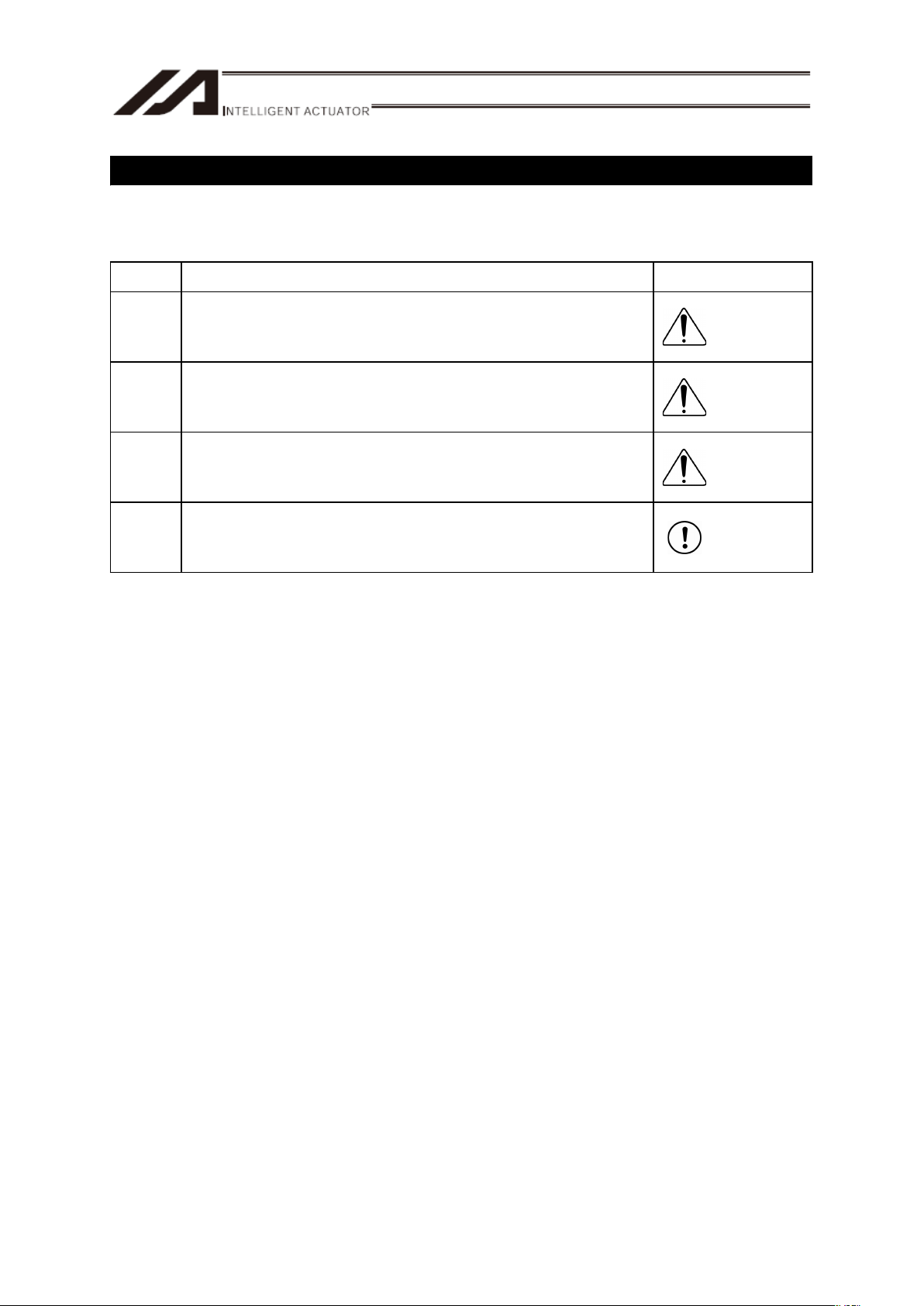
The safety precautions are divided into “Danger”, “Warning”, “Caution” and “Notice” according to
the warning level, as follows, and described in the Instruction Manual for each model.
Level Degree of Danger and Damage Symbol
Danger
This indicates an imminently hazardous situation which, if the
product is not handled correctly, will result in death or serious
injury.
Danger
Warning
This indicates a potentially hazardous situation which, if the
product is not handled correctly, could result in death or serious
injury.
Warning
Caution
This indicates a potentially hazardous situation which, if the
product is not handled correctly, may result in minor injury or
property damage.
Caution
Notice
This indicates lower possibility for the injury, but should be kept
to use this product properly.
Notice
Page 14

8
Precautions
1. Do not set speeds and accelerations/decelerations equal to or greater than the
respective ratings.
If the actuator is operated at a speed or acceleration/deceleration exceeding the allowable value,
abnormal noise or vibration, failure, or shorter life may result.
2. Set the load inertia and allowable load moment within the range of allowable
range.
It may cause a shortened life of the product, abnormal noise, vibration or malfunction if operation is
performed with the load beyond the load inertia or allowable load moment.
3. Ensure use of the product in the specified conditions, environments and ranges.
Operation out of the guarantee could cause a drop in performance or malfunction of the product.
Page 15

9
Names of the Parts
[RS-30]
Cover
Actuator Cable
Rotary Axis
Home Limit Switch
Cover
[RS-60]
Cover
Actuator Cable
Rotary Axis
Home Limit Switch
Cover
Page 16

10
Page 17

11
1. Specifications Check
1.1 Product Check
The standard configuration of this product is comprised of the following parts.
Check the packed items against the packing specification. Should you find a wrong model or any
missing item, please contact your IAI dealer or IAI.
1.1.1 Parts
No. Name Model number Quantity Remarks
1 Main Body
Refer to “How to Read the Model
Nameplate” and “How to Read the
Model Number”.
1
Accessories
2
Motor • Encoder Cables
(Note 1)
1 set
3 First Step Guide 1
4
Instruction Manual
(CD/DVD)
1
5 Safety Guide 1
Note 1 The motor • encoder cables differ between the standard model and robot cable. [Refer to 1.4
“Motor • Encoder Cables”.]
1.1.2 Related Instruction Manuals for the Each Controller Supported by this Product
Shown below is a list of the instruction manuals for the controllers related to this product which is
recorded in Instruction Manual (CD/DVD).
(1) XSEL-J/K Controller
No. Name Manual No.
1 XSEL-J/K Controller Instruction Manual ME0116
2 PC software IA-101-X-MW/IA-101-X-USBMW Instruction Manual ME0154
3 Teaching Pendant SEL-T/TD/TG Instruction Manual ME0183
4 Teaching Pendant IA-T-X/XD Instruction Manual ME0160
5 DeviceNet Instruction Manual ME0124
6 CC-Link Instruction Manual ME0123
7 PROFIBUS Instruction Manual ME0153
8 XSEL Ethernet Instruction Manual ME0140
9 Multi-Point I/O Board Instruction Manual ME0138
10 Multi-Point I/O Board Dedicated Terminal Board Instruction Manual ME0139
1. Specications Check
Page 18

1. Specications Check
12
(2) XSEL-P/Q Controller
No. Name Manual No.
1 XSEL-P/Q Controller Instruction Manual ME0148
2 XSEL-P/Q/PX/QX RC Gateway Function Instruction Manual ME0188
3 PC software IA-101-X-MW/IA-101-X-USBMW Instruction Manual ME0154
4 Teaching Pendant SEL-T/TD/TG Instruction Manual ME0183
5 Teaching Pendant IA-T-X/XD Instruction Manual ME0160
6 DeviceNet Instruction Manual ME0124
7 CC-Link Instruction Manual ME0123
8 PROFIBUS Instruction Manual ME0153
(3) SSEL Controller
No. Name Manual No.
1 SSEL Controller Instruction Manual ME0157
2 PC software IA-101-X-MW/IA-101-X-USBMW Instruction Manual ME0154
3 Teaching Pendant SEL-T/TD/TG Instruction Manual ME0183
4 Teaching Pendant IA-T-X/XD Instruction Manual ME0160
5 DeviceNet Instruction Manual ME0124
6 CC-Link Instruction Manual ME0123
7 PROFIBUS Instruction Manual ME0153
(4) SCON Controller
No. Name Manual No.
1 SCON Controller Instruction Manual ME0161
2 SCON-CA Controller Instruction Manual ME0243
3 PC software RCM-101-MW/RCM-101-USB Instruction Manual ME0155
4 Teaching Pendant CON-T/TG Instruction Manual ME0178
5 Touch Panel Teaching CON-PT/PD/PG Instruction Manual ME0227
6 Simple Teaching Pendant RCM-E Instruction Manual ME0174
7 Data Setter RCM-P Instruction Manual ME0175
8 Touch Panel Display RCM-PM-01 Instruction Manual ME0182
9 DeviceNet Instruction Manual ME0124
10 CC-Link Instruction Manual ME0123
11 PROFIBUS Instruction Manual ME0153
1.1.3 How to Read the Model Nameplate
MODEL RS-I-30-50-360-T2-S-K
SERIAL No. 900014180 MADE IN JAPAN
Model
Serial numbe
r
Page 19

13
1.1.4 How to Read the Model Number
RS I 30 50 360 T2 S K **
Note 1 Identification for IAI use only: This may be marked for the purpose of IAI. This is not to indicate
the manufacturing model code.
Series name
<Encoder type>
A : Absolute
I : Incremental
<Motor type>
30 : 30W
60 : 60W
<Deceleration ratio>
50 : 1/50
100 : 1/100
<Operation area>
360 : 360q
Identification for IAI use only
(Note1)
<Option>
K : With keyway (output shaft)
L : Home limit switch
<Cable length>
N : None
S : 3m
M : 5m
XƑƑ : Specified Length
<Controller>
T1 : XSEL-J/K
T2 : SCON
SSEL
XSEL-P/Q
1. Specications Check
Page 20

1. Specications Check
14
1.2 Specification
Model RS-30
Deceleration ratio 1/50 1/100
Operation area
rad (q) 0 to 2S (360)
Rated output W 30
Rated speed
rad/sec (q/sec) 2S (360) S (180)
Rated torque N•m (kgf•cm) 3.3 (34.1) 6.65 (68.2)
Positioning repeatability
rad (q)
±4.9×10
-4
(±0.028)
Lost motion
rad (q)
8.7×10
-4
(0.05) 4.35×10⁻⁴(0.025)
Number of encoder pulses P/R 2,048
Allowable thrust load N (kgf) 392 (40)
Model RS-60
Deceleration ratio 1/50 1/100
Operation area
rad (q) 0 to 2S (360)
Rated output W 60
Rated speed
rad/sec (q/sec) 2S (360) S (180)
Rated torque N•m (kgf•cm) 5.58 (57) 11.1 (113)
Positioning repeatability
rad (q)
±4.9×10
-4
(±0.028)
Lost motion
rad (q)
4.35×10
-4
(0.025) 4.35×10⁻⁴ (0.025)
Number of encoder pulses P/R 2,048
Allowable thrust load N (kgf) 980 (100)
Page 21

15
(1) Transportable Weight
[Refer to 4.2 Weight of the Loaded Object]
(2) Allowable Load Moment of Actuator
Allowable load moment
(Fig. 1)
Load inertia
Deflection of the output
shaft
(Fig. 2)
Type
Deceleration
ratio
N•m (kgf•cm) kg•m
2
(kgf•cm•s2) mm
1/50 0.058 (0.59)
RS-30
1/100
9.8 (100) or less
0.23 (2.35)
0.045 or less
1/50 0.11 (1.1)
RS-60
1/100
23.5 (240) or less
0.42 (4.3)
0.066 or less
(Fig. 1) (Fig. 2)
1. Specications Check
Page 22

1. Specications Check
16
1.3 Option
1.3.1 With keyway (Model code: K)
It is available as an option with a keyway for positioning on the output shaft of rotary axis.
1.3.2 Home Limit Switch (Model code: L)
In ordinary home-return operation, the “pressing method” is adopted in which the actuator is pressed
against the stopper and detects the Z-phase after reversing.
The “Home limit switch” is an option that does not adopt this pressing method but adopts a proximity
sensor to perform the home-return operation.
Page 23

17
1.4 Motor • Encoder Cables
1.4.1 Motor Cable (for XSEL-J/K/P/Q, SSEL, SCON)
CB-X-MAƑƑƑ
L
Controller end
4
1
1
4
Wiring Color Signal No.
0.75sq
GN
RD
WT
BK
PE
U
V
W
1
2
3
4
WiringColorSignalNo.
0.75sq
(Crimped)
RD
WT
BK
GN
U
V
W
PE
1
2
3
4
Mechanical end
(10)(20)
(16)
(
φ
9)
(21)
(18)
(41)
(Front View) (Front View)
1.4.2 Encoder Cable (for XSEL-J/K)
CB-X-PAƑƑƑ
L
1
9
Wiring Color Signal No.
0.15sq
(Crimped)
1
2
3
4
5
6
7
8
9
10
11
12
13
14
15
The shield is clamped to the hood
WiringColorSignalNo.
0.15sq
(Crimped)
1
2
3
4
5
6
7
8
9
Ground wire and braided shield wires
(8)
(14)
(57)
(25)
(
φ
8)
(36)
(16)
(33)
(Front View) (Front View)
Controller end
Mechanical end
BAT+
BAT-
SD
SD
VCC
GND
FG
BK-
BK+
BK
YW
BL
OR
GN
BR
GY
RD
–
–
–
–
–
–
–
SD
SD
BAT+
BATVCC
GND
BKBK+
–
–
–
–
–
–
–
BL
OR
BK
YW
GN
BR
GY
RD
Ground
1. Specications Check
Page 24

18
1.4.3 Limit Switch Cable (for XSEL-J/K)
CB-X-LCƑƑƑ
L
1
6
1
6
Wiring Color Signal No.
AWG24
6
5
4
3
2
1
WiringColorSignalNo.
AWG24
(
Crimped
)
1
2
3
4
5
6
Note) 1B indicates one black dot mark.
(8)
(12)
(18)
(
φ
6)
(30)
(12)
(18)
(22)
(Front View)
(Front View)
Controller end
Mechanical end
24VOUT
N
LS
CREEP
OT
RSV
24VOUT
N
LS
CREEP
OT
RSV
LBL
PK
GN
OR
GY
1B/LBL
LBL
PK
GN
OR
GY
1B/LBL
1.4.4 Encoder Cable (for XSEL-P/Q, SSEL, SCON, LS equipped type connection)
CB-X1-PLAƑƑƑ
(41) (14)
(13)
(37)
LS
end
(8)
(18)(25)
Ground wire and braided shield wires
AWG26
AWG26
(Soldered)
10
11
12
13
26
25
24
23
9
18
19
1
2
3
4
5
6
7
8
14
15
16
17
20
21
22
AWG26
The shield is clamped to the hood
1
9
1
13
14
26
6
1
L
(White/blue in cable color indicates the colors of line/insulator.)
(Front View)
Controller end
Mechanical end
Wiring Color Signal No.
WiringColorSignalNo.
WiringColorSignalNo.
WT/BL
WT/YW
WT/RD
WT/BK
WT/PL
WT/GY
E24V
0V
LS
CREEP
OT
RSV
BAT+
BAT-
SD
SD
VCC
GND
FG
BK-
BK+
PL
GY
OR
GN
RD
BK
Ground
BL
YW
(Crimped)
(Crimped)
–
–
–
–
–
–
E24V
0V
LS
CREEP
OT
RSV
A+
A-
B+
B-
Z+
Z-
SRD+
SRD-
BAT+
BAT-
VCC
GND
BKR-
BKR+
–
–
–
–
–
–
–
–
–
–
–
–
WT/BL
WT/YW
WT/RD
WT/BK
WT/PL
WT/GY
OR
GN
PL
GY
RD
BK
BL
YW
1
2
3
4
5
6
7
8
9
1
2
3
4
5
6
1. Specications Check
Page 25

19
2. Installation
2.1 Transportation
[1] Handling of the Robot
Unless otherwise specified, the actuators are wrapped individually when the product is shipped out.
(1) Handling of the Packed Product
x Do not damage or drop. The package is not applied with any special treatment that enables it to
resist an impact caused by a drop or crash.
x An operator should never attempt to carry a heavy package on their own. Also, use an
appropriate way for transportation.
x If the shipping box is to be left standing, it should be in a horizontal position. Follow the
instruction if there is any for the packaging condition.
x Do not step or sit on the package.
x Do not put any load that may cause a deformation or breakage of the package.
(2) Handling after Unpackaged
x Do not carry the actuator by holding the cable, or do not move it by pulling the cable.
x Hold the body base when transporting the actuator.
x Do not hit or drop the product while carrying.
x Do not give any excessive force to any of the sections in the actuator.
2. Installation
Page 26

2. Installation
20
[2] Handling of Multi-Axes Type
This is the case that this product is delivered with other actuators being combined. Multi-axes type will
be delivered in a package with an outer case fixed to a wooden base.
(1) Handling of the Packed Product
x
Do not damage or drop. The package is not applied with any special treatment that enables
it to resist an impact caused by a drop or crash.
x An operator should never attempt to carry a heavy package on their own. Also, use an
appropriate way for transportation.
x When suspending the package using ropes, pass the ropes from underneath the
reinforcement frames at the bottom of the base. When lifting with a forklift, also place the
forks underneath the base.
x Do not apply an impact on the package or let it bounce when putting it down.
x Do not step or sit on the package.
x Do not put any load that may cause a deformation or breakage of the package.
(2) Handling after Unpackaged
x
Appropriately fix the end of the actuators if it is overhanging so it would not widely shake
with external vibration. If the actuator assembly is transported without the ends being
secured, do not apply an impact of 0.3G or more.
x In the case that the actuator needs to be carried up with ropes or another method, be sure to
use an appropriate cushioning to avoid the robot being deformed or put on an excessive
pressure. And also, be sure to keep the robot in a stable and horizontal posture. Make a tool
to utilize the attachment holes and tapped holes on the actuator and attach it if necessary.
x Do not attempt to apply load to the actuator. Also, avoid the cables being pinched or caused
an excessive deformation.
[3] Handling of Robot Mounted on Mechanical Equipment (System)
Followings are the cautions for when transporting the actuators installed in the machinery
equipment (system) in the whole system.
x If any end of the actuator is overhanging, secure it properly to avoid significant movement
due to external vibration. If the actuator assembly is transported without the ends being
secured, do not apply an impact of 0.3G or more.
x Do not attempt to apply load to actuators when hanging the machinery equipment (system)
with tools such as a rope. Also, avoid the cables being pinched or caused an excessive
deformation.
Page 27

21
2.2 Installation and Storage • Preservation Environment
[1] Installation Environment
The actuator should be installed in a location other than those specified below.
In general, the installation environment should be one in which an operator can work without protective
gear.
Also provide sufficient work space required for maintenance inspection.
x Where the actuator receives radiant heat from strong heat sources such as heat treatment furnaces
x Where the ambient temperature exceeds the range of 0 to 40qC
x Where the temperature changes rapidly and condensation occurs
x Where the relative humidity exceeds 85% RH
x Where the actuator receives direct sunlight
x Where the actuator is exposed to corrosive or combustible gases
x Where the ambient air contains a large amount of powder dust, salt or iron (at level exceeding what is
normally expected in an assembly plant)
x Where the actuator is subject to splashed water, oil (including oil mist or cutting fluid) or chemical
solutions
x Where the actuator receives impact or vibration
If the actuator is used in any of the following locations, provide sufficient shielding measures:
x Where noise generates due to static electricity, etc.
x Where the actuator is subject to a strong electric or magnetic field
x Where the actuator is subject to ultraviolet ray or radiation
[2] Storage • Preservation Environment
The storage • preservation environment should be similar to the installation environment. In addition,
make sure condensation will not occur when the actuator is to be stored or preserved for a long period
of time. Unless specified, we do not include drying agents when shipping the actuator. If you are storing
the actuator in an environment where condensation might occur, you must treat the entire shipping box,
or treat the actuator itself after unpacking, to prevent condensation. The unit can withstand
temperatures up to 60qC during a short storage/preservation period, but only up to 50qC if the
storage/preservation period is longer than one month.
The actuator should be lying flat during storage • preservation.
If the actuator is to be stored in a packed state, follow the specified actuator position if indicated.
[3] Handling of the Robot Mounted on Mechanical Equipment (System)
The following are the cautions for when transporting the actuators installed in the machinery equipment
(system) in the whole system.
x Affix the table so they would not move while transporting.
x If any end of the actuator is overhanging, secure it properly to avoid significant movement due to
external vibration. If the actuator assembly is transported without the ends being secured, do not
apply an impact of 0.3G or more.
x Do not attempt to apply load to actuators or connector box when hanging the machinery equipment
(system) with tools such as a rope. Also, avoid the cables being pinched or caused an excessive
deformation.
2. Installation
Page 28

2. Installation
22
2.3 Installation
This chapter explains how to install the actuator on your mechanical system.
[1] Installation
Follow the information below when installing the actuator, as a rule.
Do pay attention to these items (except with custom-order models).
{ : Possible u : Not possible
Horizontal
installation
Vertical
installation
Sideway
installation
Ceiling mount
installation
{ { { {
Page 29

23
[2] Installation of the Main Unit
Have the unit attached following the steps below;
1) Unscrew the flat-head screws on the sides of the unit cover and remove the cover.
2) There are 9mm through holes at 4 points on the main unit. Affix the unit with M8 screws.
3) Put the cover back on the unit and affix with the flat-head screws.
Mounting screw
Mounting screw
Cover
Flat-head screw
Flat-head screw
Flat-head screw
Flat-head screw
Tightening screws
x Use hexagonal socket head bolts for the male threads for installing the base.
x Use of high-tension bolts meeting at least ISO-10.9 is recommended.
x Use appropriate screws suitable for the attachment holes and attachment grooves.
x Do not attempt to use a general-purposed spring washer. Doing so may make the screws even
looser.
2. Installation
Page 30

2. Installation
24
[3] Attachment of the Arm and Tools
Apply split tightening or shrink discs when attaching an arm or tools to the spindle (main shaft) on the
main body.
Tool attachment
plate
Power lock, etc.
To attach a tool such as
a gripper to the end
Page 31

25
3. Connecting with the Controller
For the controller, only the dedicated controller manufactured by our company can be used.
Using other controllers may cause a problem such as burning the product, ignition or generating heat.
Use the dedicated cable enclosed in the package when connecting the actuator and the controller.
[Connecting with XSEL-J/K Controller]
Dedicated cable
(Connect actuator with the dedicated controller)
r = 51mm or mere (Movable Use)
r = 34mm or mere (Fixed Use)
Dedicated controller
XSEL-J/K
x Motor Cable CB-X-MA***
x Encoder Cable CB-X-PA***
x Limit Switch Cable CB-X-LC***
*** indicates the cable length.
Up to 30m can be specified.
Example) 080 = 8 m
[Connecting with XSEL-P/Q, SSEL, SCON Controller]
Dedicated cable
(Connect actuator with the dedicated controller)
r = 58mm or mere (Movable Use)
r = 38mm or mere (Fixed Use)
Dedicated controller
XSEL-P/Q, SSEL, SCON
x Motor Cable CB-X-MA***
x Encoder Cable with LS CB-X1-PLA***
*** indicates the cable length.
Up to 30m can be specified.
Example) 080 = 8 m
3. Connecting with the Controller
Page 32
3. Connecting with the Controller
26
When designing an application system, incorrect wiring or connection of each cable may cause
unexpected problems such as a disconnected cable or poor contact. The following explains examples
of prohibited handling of cables.
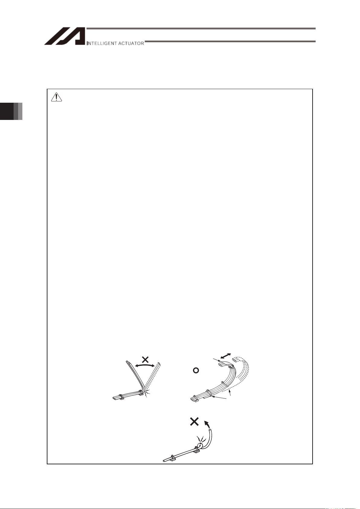
Warning: For wiring, please follow the warnings stated below. When constructing a
system as the machinery equipment, pay attention to the wiring and
connection of each cable so they are conducted properly. Not following them
may cause not only a malfunction such as cable breakage or connection
failure, or an operation error, but also electric shock or electric leakage, or
may even cause a fire.
• Use dedicated cables of IAI indicated in this instruction manual. Contact us if you
wish to have a change to the specifications of the dedicated cables.
• Make sure to turn the power off in the process of power line or cable connection or
disconnection.
• Do not attempt to cut a dedicated cable with connectors on both ends to extend,
shorten or re-joint it.
• Hold the dedicated cable to avoid mechanical force being applied to the terminals and
connectors.
• Use a cable pipe or duct to have an appropriate protection when there is a possibility
of mechanical damage on a dedicated cable.
• In case a dedicated cable is to be used at a moving part, make sure to lay out the
cable without applying any force to pull the connector or extreme bend on the cable.
Do not attempt to use the cable with a bending radius below the allowable value.
• Make certain that the connectors are plugged properly. Insufficient connection may
cause an operation error, thus it is extremely risky.
• Do not lay out the cables to where the machine runs over them.
• Pay attention to the cable layout so it would not hit peripherals during an operation. In
case it does, have an appropriate protection such as a cable track.
• When a cable is used hanging on the ceiling, prevent an environment that the cable
swings with acceleration or wind velocity.
• Make sure there is not too much friction inside the cable storage equipment.
• Do not apply radiated heat to power line or cables.
• Have a sufficient radius for bending, and avoid a bend concentrating on one point.
Steel Strap
(Piano Wire)
Tie them up softly.
• Do not let the cable bend, kink or twist.
Page 33

27
• Do not pull the cable with a strong force.
• Pay attention not to concentrate the twisting force to one point on a cable.
• Do not pinch, drop a heavy object onto or cut the cable.
• When a cable is fastened to affix, make sure to have an appropriate force and do not
tighten too much.
Do not use spiral tube in any
position where cables are bent
frequently.
• PIO line, communication line, power and driving lines are to be put separately from
each other and do not tie them together. Arrange so that such lines are independently
routed in the duct.
Power Line
Duct
I/O Line
(Flat Cable, etc.)
3. Connecting with the Controller
Page 34

28
• If using a cable track, arrange the wiring so that there is no entanglement or kink of
the cables in the cable carrier or flexible tube, and do not bind the cables so that the
cables are relatively free. (Arrange the wiring so the cables are not to be pulled when
bent.)
• The occupied volume rate for the cables, etc., inside the cable track should be 60% or
less.
Cable
Cable Track
3. Connecting with the Controller
Page 35

29
4. Operational Conditions
4.1 Load Inertia
Operate with the load inertia within the allowable range.
Load inertia
Type
Deceleration
ratio
kg•m
2
(kgf•cm•s2)
1/50 0.058 (0.59)
RS-30
1/100 0.23 (2.35)
1/50 0.11 (1.1)
RS-60
1/100 0.42 (4.3)
٧ Regarding the load inertia
The rotary actuator is an actuator that applies a rotational torque to the loaded work piece and
makes the work piece have a rotational motion.
The rotational torque applies the load inertia and angular acceleration that can be figured out with
the following formula.
T = J•Į
T : Torque N•m (kgf•cm)
J : Load inertia kg•m
2
(kgf•cm•s2)
Į : Angular acceleration rad/s
2
i.e. applying a torque to an object with load inertia generates an angular acceleration. Therefore, for
the rotary actuator, the loadable amount is expressed with the load inertia.
٧ Calculation of the Load Inertia
Load inertia is a specific value for an object determined by the weight and profile.
It is to be calculated as;
J = ³ r
2
dM
r : Distance from center
dM : Small mass
For example, if the loaded work piece is offset from the rotary shaft, the following formula can be
applied.
J = M•r
2
M : Mass of the loaded piece (kg)
r : Distance from the center (Offset distance) (m)
(Offset distance)
r
M
(Loaded
work piece)
typically Z is used for
angular velocity
4. Operational Conditions
Page 36

4. Operational Conditions
30
Shown below is the formula for the load inertial applied to a cylinder and rectangular parallelepiped.
1) Cylinder (including thin disc) 2) Thin rectangular
(rectangular parallelepiped)
3) Thin rectangular plate
(rectangular parallelepiped)
Point of rotation :
Center shaft
Point of rotation :
Point that goes through the
center of the gravity of the
plate and perpendicular to
the plate (same for when the
plate is thickened)
Point of rotation :
Perpendicular to the plate
and one-ended
J = M •
—
r
2
2
J = M • ———
a
2
+ b
2
12
a
b
J = M1 • ———— +
M2 • ————
4a2 + b
2
12
a
2
b
a
1
1
4a2 + b
2
12
2
J : Load inertia (kg•m2)
M : Mass (kg)
r, a, b, a
1
, a2 : Distance (m)
Page 37

31
4.2 Weight of the Loaded Object
Take the following as a reference for the weight of the loaded work piece applied to the rotary axis
output shaft.
A For loaded object with a disc shape just below rotary axis shaft
(Radius of disc)
r
RS-60
RS
-
30
Mass of disc (kg)
Radius of disc (cm)
50
40
30
20
10
10 20 30 40
0
<Deceleration ratio 1/50>
RS-60
RS
-
30
Mass of disc (kg)
Radius of disc (cm)
50
40
30
20
10
10 20 30 40
0
<Deceleration ratio 1/100>
B For a loaded object offset from rotary axis shaft
(Offset distance)
r
(Loaded
work piece)
RS-60
RS-30
25
20
15
10
5
10 20 30 40
0
<Deceleration ratio 1/50>
Mass of loaded piece (kg)
RS-60
RS-30
Mass of loaded piece (kg)
25
20
15
10
5
10 20 30 40
0
<Deceleration ratio 1/100>
Offset distance (cm) Offset distance (cm)
4. Operational Conditions
Page 38

32
5. Maintenance Inspection
5.1 Inspection Items and Schedule
Have an appearance check at the start of operation.
5.2 Appearance Check
An appearance check should check the following things.
Main Body Loose actuator mounting bolts, other loose items
Cables Scratches, proper connections
Overall Irregular noise, vibration
5.3 Cleaning
Ɣ Clean exterior surfaces as necessary.
Ɣ Use a soft cloth to wipe away dirt and buildup.
Ɣ Do not blow too hard with compressed air as it may cause dust to get in through the gaps.
Ɣ Do not use oil-based solvents as they can harm lacquered and painted surfaces.
Ɣ To remove severe buildup, wipe gently with a soft cloth soaked in a neutral detergent or alcohol.
5. Maintenance Inspection
Page 39

33
6. External Dimensions
6.1 RS-30
23
φ
14h7
5×5 key
64.5
6
29
29.5
29.5
56
58
56
20
φ
14h7
4-9 drill
50
25
8.5
101.5
11
11
90
52 22
160
2-φ8H7 Reamed, Depth 10 (from the opposite side)
(300)
Cable Joint
Connector
112
Dimensions for the keyway shaft
Home Limit Switch
Weight 2.0kg
6.2 RS-60
Dimensions for the keyway shaft
6
38
39
83
112
11
11
90
126.5
60
30
20
φ
h7
4-9 drill
198 (300)
11.5
39
76
56
56
20
28
20
φ
h7
6×6 key
Home Limit Switch
2-φ8H7 Reamed, Depth 10 (from the opposite side)
Cable Joint
Connector
2230
Weight 3.2kg
6. External Dimensions
Page 40

7. Life
34
7. Life
Shown in the graph is the life of the main bearing and the speed reducer (reference).
The graph shows the case in which a load of dynamic allowable moment is applied.
Calculate the accumulation of rotational angles per minute to read the life (reference).
0
2000
4000
6000
8000
100 00
120 00
1,000 10,000 100 ,000 1,0 00,000 10,000,0 00 10 0,000,00 0 1,000,000 ,000
Estimated Life Time [Hours]
Accumulation of Rotational Angles per Minute [deg]
Speed ReducerSpeed Reducer Main BearingMain Bearing
RS-30, Gear Ratio = 1/50
0
2000
4000
6000
8000
100 00
120 00
1,000 10,000 100 ,000 1,0 00,000 10,000, 000 1 00,000 ,000 1,000,00 0,000
Estimated Life Time [Hours]
Accumulation of Rotational Angles per Minute [deg]
Speed Reducer
Speed Reducer Main Bearing
Main Bearing
RS-30, Gear Ratio = 1/100
Page 41

35
0
2000
4000
6000
8000
100 00
120 00
1,000 10, 000 10 0,000 1,000 ,000 10,000, 000 100,000,000 1, 000,000, 000
Estimated Life Time [Hours]
Accumulation of Rotational Angles per Minute [deg]
Speed ReducerSpeed Reducer Main BearingMain Bearing
RS-60, Gear Ratio = 1/50
0
2000
4000
6000
8000
100 00
120 00
1,000 10, 000 100,000 1,000 ,000 10,000, 000 100,00 0,000 1, 000,000, 000
Estimated Life Time [Hours]
Accumulation of Rotational Angles per Minute [deg]
Speed Reducer
Speed Reducer Main BearingMain Bearing
RS-60, Gear Ratio = 1/100
7. Life
Page 42

8. Warranty
36
8. Warranty
8.1 Warranty Period
One of the following periods, whichever is shorter:
y 18 months after shipment from our company
y 12 months after delivery to the specified location
y 2,500 hours of operation
8.2 Scope of the Warranty
Our products are covered by warranty when all of the following conditions are met. Faulty products
covered by warranty will be replaced or repaired free of charge:
(1) The breakdown or problem in question pertains to our product as delivered by us or our authorized
dealer.
(2) The breakdown or problem in question occurred during the warranty period.
(3) The breakdown or problem in question occurred while the product was in use for an appropriate
purpose under the conditions and environment of use specified in the Instruction Manual and
catalog.
(4) The breakdown or problem in question was caused by a specification defect or problem, or by the
poor quality of our product.
Note that breakdowns due to any of the following reasons are excluded from the scope of warranty:
[1] Anything other than our product
[2] Modification or repair performed by a party other than us (unless we have approved such
modification or repair)
[3] Anything that could not be easily predicted with the level of science and technology available
at the time of shipment from our company
[4] A natural disaster, man-made disaster, incident or accident for which we are not liable
[5] Natural fading of paint or other symptoms of aging
[6] Wear, depletion or other expected result of use
[7] Operation noise, vibration or other subjective sensation not affecting function or maintenance
Note that the warranty only covers our product as delivered and that any secondary loss arising from a
breakdown of our product is excluded from the scope of warranty.
8.3 Honoring the Warranty
As a rule, the product must be brought to us for repair under warranty.
8.4 Limited Liability
(1) We shall assume no liability for any special damage, consequential loss or passive loss such as a
loss of expected profit arising from or in connection with our product.
(2) We shall not be liable for any program or control method created by the customer to operate our
product or for the result of such program or control method.
Page 43

37
8.5 Conditions of Conformance with Applicable Standards/Regulations, Etc., and Applications
(1) If our product is combined with another product or any system, device, etc., used by the customer,
the customer must first check the applicable standards, regulations and/or rules. The customer is
also responsible for confirming that such combination with our product conforms to the applicable
standards, etc. In such a case we will not be liable for the conformance of our product with the
applicable standards, etc.
(2) Our product is for general industrial use. It is not intended or designed for the applications
specified below, which require a high level of safety. Accordingly, as a rule our product cannot be
used in these applications. Contact us if you must use our product for any of these applications:
[1] Medical equipment pertaining to maintenance or management of human life or health
[2] A mechanism or mechanical equipment intended to move or transport people (such as a
vehicle, railway facility or aviation facility)
[3] Important safety parts of mechanical equipment (such as safety devices)
[4] Equipment used to handle cultural assets, art or other irreplaceable items
(3) Contact us at the earliest opportunity if our product is to be used in any condition or environment
that differs from what is specified in the catalog or Instruction Manual.
8.6 Other Items Excluded from Warranty
The price of the product delivered to you does not include expenses associated with programming, the
dispatch of engineers, etc. Accordingly, a separate fee will be charged in the following cases even
during the warranty period:
[1] Guidance for installation/adjustment and witnessing of test operation
[2] Maintenance and inspection
[3] Technical guidance and education on operating/wiring methods, etc.
[4] Technical guidance and education on programming and other items related to programs
8. Warranty
Page 44

38
Change History
Revision Date Description of Revision
June 2012 Third edition
Revised overall
Change History
Page 45

Page 46

Manual No.: ME3609-3A (June 2012)
The information contained in this document is subject to change without notice for purposes of
product improvement.
Copyright © 2012. Jun. IAI Corporation. All rights reserved.
12.06.000
Head Office: 577-1 Obane Shimizu-KU Shizuoka City Shizuoka 424-0103, Japan
TEL +81-54-364-5105 FAX +81-54-364-2589
website: www.iai-robot.co.jp/
Ober der Röth 4, D-65824 Schwalbach am Taunus, Germany
TEL 06196-88950 FAX 06196-889524
SHANGHAI JIAHUA BUSINESS CENTER A8-303, 808, Hongqiao Rd. Shanghai 200030, China
TEL 021-6448-4753 FAX 021-6448-3992
website: www.iai-robot.com
Technical Support available in USA, Europe and China
Head Office: 2690 W. 237th Street, Torrance, CA 90505
TEL (310) 891-6015 FAX (310) 891-0815
Chicago Office: 1261 Hamilton Parkway, Itasca, IL 60143
TEL (630) 467-9900 FAX (630) 467-9912
TEL (678) 354-9470 FAX (678) 354-9471
website: www.intelligentactuator.com
Atlanta Office: 1220 Kennestone Circle, Suite 108, Marietta, GA 30066
 Loading...