

Page 1

RCS Series
ROBO Cylinder Controller
RCS-E Type
Operation Manual Seventh Edition
Page 2

Page 3

Please Read Before Use
Thank you for purchasing our product.
This Operation Manual explains the handling methods, structure and maintenance of this product, among others,
providing the information you need to know to use the product safely.
Before using the product, be sure to read this manual and fully understand the contents explained herein to
ensure safe use of the product.
The CD that comes with the product contains operation manuals for IAI products.
When using the product, refer to the necessary portions of the applicable operation manual by printing them out
or displaying them on a PC.
After reading the Operation Manual, keep it in a convenient place so that whoever is handling this product can
reference it quickly when necessary.
[Important]
This Operation Manual is original.
The product cannot be operated in any way unless expressly specified in this Operation Manual. IAI shall
assume no responsibility for the outcome of any operation not specified herein.
Information contained in this Operation Manual is subject to change without no tice for the purpose of
product improvement.
If you have any question or comment regarding the content of this manual, please contact the IAI sales
office near you.
Using or copying all or part of this Operation Manual without permi ssion is prohibited.
The company names, names of products and trademarks of each company shown in the sentences are
registered trademarks.
Page 4

CAUTION
(1) Hold · Servo ON Signal
When operating the RCS (ROBO cylinder) controller, you will need to turn ON the Hold &
Servo ON signal Input Signal of PIO.
In case the Hold Stop Input Signal of PIO remains OFF, RCS controller will not move due to
hold status. Therefore, please be careful.
(2) Position 0 may be output regardless of the actual position. At the timings specified below,
the positioning completion signal turns ON no matter where the actual position is. As a
result, the output status becomes “Position 0.”
1. When the power is turned on
2. When the emergency stop is reset
3. When the alarm is reset
4. When a reset is performed after hold
Be extra careful when using Position 0.
(3) With the absolute type, 0E5 (Encoder Reception Error) will be displayed under certain
conditions, such as when the power is first turned on after disconnecting the battery or PG
cable. This display does not indicate fault. Perform an absolute reset in accordance with
the specified procedure.
(4) Recommendation for backing up latest data
This controller uses nonvolatile memory to store position table data and parameters.
Although data in the memory is retained even after the power is cut off, the stored data will
be lost if the nonvolatile memory is damaged.
It is therefore recommended that you regularly back up the latest position table data and
parameters in case of accidental data loss. Regular backup will also let you restore data
quickly if the controller must be replaced for other reasons.
Use the following methods to back up data:
[1] Use the PC software to save the data to a CD or FD.
[2] Create a position table sheet or parameter sheet and keep a written record of backup.
Page 5

Table of Contents
Safety Guide.......................................................................................................1
1. Overview........................................................................................................1
1.1 Forward .....................................................................................................................................................1
1.2 How to Read Model Number.....................................................................................................................2
1.3 Safety Precautions ....................................................................................................................................3
1.4 Warranty Period and Scope of Warranty...................................................................................................4
1.5 Setting Environment and Noise Measures................................................................................................5
1.6 Heat Radiation and Installation .................................................................................................................8
2. Specification .................................................................................................. 9
2.1 Base Specifications...................................................................................................................................9
2.1.1 Backup Battery (Absolute Specification)..........................................................................................10
2.2 Names and Functions of Parts................................................................................................................11
2.2.1 Names..............................................................................................................................................11
2.2.2 Functions .........................................................................................................................................11
2.2.3 Pin Assignments of the Communication Ports.................................................................................14
2.3 External Dimensions................................................................................................................................16
2.4 Connection Method .................................................................................................................................17
2.4.1 Standard Type..................................................................................................................................17
2.4.2 Absolute Specification......................................................................................................................18
2.5 Supplied Cable........................................................................................................................................19
2.5.1 I/O Flat Cable...................................................................................................................................19
2.5.2 Motor Extension Cable ....................................................................................................................19
2.6 Wiring ......................................................................................................................................................21
2.6.1 Wiring for Power Supply/Emergency Stop.......................................................................................21
2.6.2 External Connection Diagram..........................................................................................................22
2.6.3 PIO Interface....................................................................................................................................23
2.6.4 Non-isolated External I/O Specification...........................................................................................26
3. Data Entry <Basics>.................................................................................... 28
3.1 Description of Position-Data Table ..........................................................................................................29
3.2 Explanation of Modes..............................................................................................................................33
3.3 Timing Chart............................................................................................................................................37
4. Using the Controller <Practical Steps>........................................................ 38
4.1 How to Start (Standard Type)..................................................................................................................38
4.2 How to Execute Absolute Reset (Absolute Specification).......................................................................39
4.3 Movement after Power On (Standard T ype)............................................................................................41
4.4 Positioning Mode (Back and Forth Movement between Two Points)......................................................43
4.5 Push & Hold Mode...................................................................................................................................45
4.6 Speed Change during Movement............................................................................................................47
4.7 Operation at Different Acceleration and Deceleration Settings...............................................................49
4.8 Pause ......................................................................................................................................................51
4.9 Zone Signal Output..................................................................................................................................53
4.10 Returning Home ......................................................................................................................................55
4.11 Incremental Moves..................................................................................................................................57
4.12 Notes on Incremental Mode ....................................................................................................................59
Page 6

Parameters.................................................................................................. 61
5.
5.1 Parameter Classification .........................................................................................................................61
5.2 Parameter List.........................................................................................................................................61
5.3 Parameter Settings..................................................................................................................................62
5.3.1 Parameters Relating to Actuator Stroke Range...............................................................................62
5.3.2 Parameters Relating to Actuator Operating Characteristics............................................................63
5.3.3 Parameters Relating to External Interface.......................................................................................66
5.3.4 Servo Gain Adjustment....................................................................................................................66
6. Troubleshooting...........................................................................................67
6.1 What to Do When A Problem Occurs ............................................................................................... .......67
6.2 Alarm Level Classification ..................................................................................................... .................. 68
6.3 Alarm Output by PIO ...............................................................................................................................68
6.4 Alarms, Causes and Actions ...................................................................................................................69
6.5 Messages Displayed during Operations Using Teaching Pendant or PC Software................................75
* Appendix......................................................................................................... 77
Specification List of Supported Actuators ...........................................................................................................77
Flat Type (F45) - Moments and Loading Capacity..............................................................................................78
Example of Basic RCS Positioning Sequence....................................................................................................79
Position Table Record (1/2).................................................................................................................................82
Parameter Record...............................................................................................................................................83
Change History.................................................................................................86
Page 7

Safety Guide
This “Safety Guide” is intended to ensure the correct use of this product and prevent dangers and property
damage. Be sure to read this section before using your product.
Regulations and Standards Governing Industrial Robots
Safety measures on mechanical devices are generally classified into four categori es un der the International
Industrial Standard ISO/DIS 12100, “Safety of machinery,” as follows:
Safety measures Inherent safety design
Protective guards --- Safety fence, etc.
Additional safety measures --- Emergency stop device, etc.
Information on use --- Danger sign, warnings, operation manual
Based on this classification, various standards are established in a hierarchical manner under the International
Standards ISO/IEC. The safety standards that apply to industrial robots are as follows:
Type C standards (individual safety standards) ISO10218 (Manipulating industrial robots – Safety)
JIS B 8433
(Manipulating industrial robots – Safety)
Also, Japanese laws regulate the safety of industrial robots, as follows:
Industrial Safety and Health Law Article 59
Workers engaged in dangerous or harmful operations must receive special education.
Ordinance on Industrial Safety and Health
Article 36 --- Operations requiring special education
No. 31 (Teaching, etc.) --- Teaching and other similar work involving industrial robots (exceptions
apply)
No. 32 (Inspection, etc.) --- Inspection, repair, adjustment and similar work involving industrial robots
(exceptions apply)
Article 150 --- Measures to be taken by the user of an industrial robot
Pre-1
Page 8

Requirements for Industrial Robots under Ordinance on Industrial Safety and
Health
Work area
movement
range
Inside
movement
range
Work
condition
During
automatic
operation
During
teaching, etc.
During
inspection,
etc.
Cutoff of drive source Measure Article
Signs for starting operation Article 104 Outside
Not cut off
Cut off (including
stopping of operation)
Not cut off
Cut off
Not cut off (when
inspection, etc., must
be performed during
operation)
Installation of railings, enclosures,
etc.
Sign, etc., indicating that work is in
progress
Preparation of work rules Article 150-3
Measures to enable immediate
stopping of operation
Sign, etc., indicating that work is in
progress
Provision of special education Article 36-31
Checkup, etc., before
commencement of work
To be performed after stopping the
operation
Sign, etc., indicating that work is in
progress
Preparation of work rules Article 150-5
Measures to enable immediate
stopping of operation
Sign, etc., indicating that work is in
progress
Provision of special education
(excluding cleaning and lubrication)
Article 150-4
Article 150-3
Article 150-3
Article 150-3
Article 151
Article 150-5
Article 150-5
Article 150-5
Article 150-5
Article 36-32
Pre-2
Page 9

Applicable Modes of IAI’s Industrial Robot
Machines meeting the following conditions are not classified as industrial robot s according to Notice of Ministry of
Labor No. 51 and Notice of Ministry of Labor/Labor Standards Office Director (Ki-Hatsu No. 340):
(1) Single-axis robo with a motor wattage of 80 W or less
(2) Combined multi-axis robot whose X, Y and Z-axes are 300 mm or shorter and wh ose rot ating p art, if any,
has the maximum movement range of within 300 mm
(3) Multi-joint robot whose movable radius and Z-axis are within 300 mm
Among the products featured in our catalogs, the following models are classified as industrial robots:
1. Single-axis ROBO Cylinders
RCS2/RCS2CR-SS8 whose stroke exceeds 300 mm
2. Single-axis robots
The following models whose stroke exceeds 300 mm and whose motor capacity also exceeds 80 W:
ISA/ISPA, ISDA/ISPDA, ISWA/ISPWA, IF, FS, NS
3. Linear servo actuators
All models whose stroke exceeds 300 mm
4. Cartesian robos
Any robot that uses at least one axis corresponding to one of the models specified in 1 to 3
5. IX SCARA robots
All models whose arm length exceeds 300 mm
(All models excluding IX-NNN1205/1505/1805/2515, NNW2515 and NNC1205/1505/1805/2515)
3
including the end of the rotating part
Pre-3
Page 10

Notes on Safety of Our Products
Common items you should note when performing each task on any IAI robot are explained below.
No. Task Note
1 Model
selection
2 Transportation
3 Storage/
preservation
4 Installation/
startup
This product is not planned or designed for uses requiring high degrees of safety.
Accordingly, it cannot be used to sustain or support life and must not be used in the
following applications:
[1] Medical devices relating to maintenance, management, etc., of life or health
[2] Mechanisms or mechanical devices (vehicles, railway facilities, aircraft facilities, etc.)
intended to move or transport people
[3] Important safety parts in mechani cal devices (safety devices, etc.)
Do not use this product in the following environments:
[1] Place subject to flammable gases, ignitable objects, flammables, explosives, etc.
[2] Place that may be exposed to radiation
[3] Place where the surrounding air temperature or relative humidity exceeds the
specified range
[4] Place subject to direct sunlight or radiated heat from large heat sources
[5] Place subject to sudden temperature shift and condensation
[6] Place subject to corrosive gases (sulfuric acid, hydrochloric acid, etc.)
[7] Place subject to excessive dust, salt or iron powder
[8] Place where the product receives direct vibration or impact
Do not use this product outside the specified ranges. Doing so may significantly
shorten the life of the product or result in product failure or facility stoppage.
When transporting the product, exercise due caution not to bump or drop the product.
Use appropriate means for transportation.
Do not step on the package.
Do not place on the package any heavy article that may deform the package.
When using a crane of 1 ton or more in capacity, make sure the crane operators are
qualified to operate cranes and perform slinging work.
When using a crane, etc., never hoist articles exceeding the rated load of the crane,
etc.
Use hoisting equipment suitable for the article to be hoisted. Calculate the load
needed to cut off the hoisting equipment and other loads incidental to equipment
operation by considering a safety factor. Also check the hoisting e quipment for
damage.
Do not climb onto the article while it is being hoisted.
Do not keep the article hoisted for an extended period of time.
Do not stand under the hoisted article.
The storage/preservation environment should conform to the installation environment.
Among others, be careful not to cause condensation.
(1) Installing the robot, controller, etc.
Be sure to firmly secure and affix the product (including its work part).
If the product tips over, drops, malfunctions, etc., damage or injury may result.
Do not step on the product or place any article on top. The product may tip over or the
article may drop, resulting in injury, product damage, loss of/drop in product
performance, shorter life, etc.
If the product is used in any of the following places, provide sufficient shielding
measures:
[1] Place subject to electrical noise
[2] Place subject to a strong electric or magnetic field
[3] Place where power lines or drive lines are wired nearby
[4] Place subject to splashed water, oil or chemicals
Pre-4
Page 11

No. Task Note
4 Installation/
startup
(2) Wiring the cables
Use IAI’s genuine cables to connect the actuator and controller or connect a teaching
tool, etc.
Do not damage, forcibly bend, pull, loop round an object or pinch the cables or place
heavy articles on top. Current leak or poor electrical continuity may occur, resulting in
fire, electric shock or malfunction.
Wire the product correctly after turning off the power.
When wiring a DC power supply (+24 V), pay attention to the positive and negative
polarities.
Connecting the wires in wrong polarities may result in fire, product failure or
malfunction.
Securely connect the cables and connectors so that they will not be disconnected or
come loose. Failing to do so may result in fire, electric shock or product malfunction.
Do not cut and reconnect the cables of the product to extend or shorten the cables.
Doing so may result in fire or product malfunction.
(3) Grounding
Be sure to provide class D (former class 3) grounding for the controller. G roun ding is
required to prevent electric shock and electrostatic charges, improve noise re sistance
and suppress unnecessary electromagnetic radiation.
(4) Safety measures
Implement safety measures (such as installing safety fences, etc.) to prevent entry into
the movement range of the robot when the product is moving or can be moved.
Contacting the moving robot may result in death or serious injury.
Be sure to provide an emergency stop circuit so that the product can be stopped
immediately in case of emergency during operation.
Implement safety measures so that the product cannot be started only by turning on
the power. If the product starts suddenly, injury or product damage may result.
Implement safety measures so that the product will not start upon cancellation of an
emergency stop or recovery of power following a power outage. Failure to do so may
result in injury, equipment damage, etc.
Put up a sign saying “WORK IN PROGRESS. DO NOT TURN ON POWER,” etc.,
during installation, adjustment, etc. If the power is accidently turned on, electri c shock
or injury may result.
Implement measures to prevent the work part, etc., from dropping due to a power
outage or emergency stop.
Ensure safety by wearing protective gloves, protective goggles and/or safety shoes,
as necessary.
Do not insert fingers and objects into openings in the product. Doing so may result in
injury, electric shock, product damage, fire, etc.
When releasing the brake of the vertically installed actuator, be careful not to let the
actuator drop due to its dead weight, causing pinched hands or damaged work part,
etc.
5 Teaching
Whenever possible, perform teaching from outside the safety fences. If teaching must
be performed inside the safety fences, prepare “work rules” and make sure the
operator understands the procedures thoroughly.
When working inside the safety fences, the operator should carry a handy emergency
stop switch so that the operation can be stopped any time when an abnormality
occurs.
When working inside the safety fences, appoint a safety watcher in addition to the
operator so that the operation can be stopped any time when an abnormality occurs.
The safety watcher must also make sure the switches are not operated inadvertently
by a third party.
Put up a sign saying “WORK IN PROGRESS” in a conspicuous location.
Pre-5
Page 12

No. Task Note
When releasing the brake of the vertically installed actuator, be careful not to let the
actuator drop due to its dead weight, causing pinched hands or damaged load, etc.
* Safety fences --- Indicate the movement range if safety fences are not provided.
6 Confirmation
operation
7 Automatic
operation
8 Maintenance/
inspection
9 Modification The customer must not modify or disassemble/assemble the product or use
10 Disposal When the product becomes no longer usable or necessary, dispose of it properly as an
After teaching or programming, carry out step-by-step confirmation operation before
switching to automatic operation.
When carrying out confirmation operation inside the safety fences, follow the specified
work procedure just like during teaching.
When confirming the program operation, use the safety speed. Failure to do so may
result in an unexpected movement due to programming errors, etc., causing injury.
Do not touch the terminal blocks and various setting switches while the power is
supplied. Touching these parts may result in electric shock or malfunction.
Before commencing automatic operation, make sure no one is inside the safety
fences.
Before commencing automatic operation, make sure all related peripherals are ready
to operate in the auto mode and no abnormalities are displayed or indicated.
Be sure to start automatic operation from outside the safety fences.
If the product generated abnormal heat, smoke, odor or noise, stop the product
immediately and turn off the power switch. Failure to do so may result in fire or pr oduct
damage.
If a power outage occurred, turn off the power switch. Otherwise, the product may
move suddenly when the power is restored, resulting in injury or product damage.
Whenever possible, work from outside the safety fences. If work must be performed
inside the safety fences, prepare “work rules” and make sure the operator underst ands
the procedures thoroughly.
When working inside the safety fences, turn off the power switch, as a rule.
When working inside the safety fences, the operator should carry a handy emergency
stop switch so that the operation can be stopped any time when an abnormality
occurs.
When working inside the safety fences, appoint a safety watcher in addition to the
operator so that the operation can be stopped any time when an abnormality occurs.
The safety watcher must also make sure the switches are not operated inadvertently
by a third party.
Put up a sign saying “WORK IN PROGRESS” in a conspicuous location.
Use appropriate grease for the guides and ball screws by checking the operation
manual for each model.
Do not perform a withstand voltage test. Conducting this test may result in product
damage.
When releasing the brake of the vertically installed actuator, be careful not to let the
actuator drop due to its dead weight, causing pinched hands or damaged work part,
etc.
* Safety fences --- Indicate the movement range if safety fences are not provided.
maintenance parts not specified in the manual without first consulting IAI.
Any damage or loss resulting from the above actions will be excluded from the scope
of warranty.
industrial waste.
When disposing of the product, do not throw it into fire. The product may explode or
generate toxic gases.
Pre-6
Page 13
Indication of Cautionary Information
The operation manual for each model denotes safety precautions under “Danger,” “Warning,” “Caution” and
“Note,” as specified below.
Level Degree of danger/loss Symbol
Danger
Warning
Caution
Note
Failure to observe the instruction will result in an
imminent danger leading to death or serious injury.
Failure to observe the instruction may result in death
or serious injury.
Failure to observe the instruction may result in injury
or property damage.
The user should take heed of this information to
ensure the proper use of the product, although failure
to do so will not result in injury.
Danger
Warning
Caution
Note
Pre-7
Page 14

Page 15

Page 16

Page 17

1. Overview
1.1 Forward
Thank you very much for purchasing the RCS controller . Thi s manual explains the features of this machine a nd its
operating procedures.
Without knowing beforehand how to correctly use or operate the controlle r, not only will the user be unable to take
full advantage of all the functions built into this product but the user might also, inadvertently cau se damage to the
robot or shorten its life. Please read this manual as well as other manuals carefully pert aining to the product to
acquire an understanding of the proper method of handling and operating the controller. Keep this manual handy
so that you can refer to the appropriate sections as the need arises.
Also refer to the operation manuals for the various actuators you ar e using, as well as the operation ma nual(s) for
the optional PC software and/or teaching pendant if applicable.
Absolute Specifications:
With the absolute home controller, once power is applied, and absolute reset is executed, you can execute
positioning without the need to home after reapplying the power. Other basic functions are the same as the
standard RCS controller.
Absolute reset is not set at time of shipment. Please execute absolute reset by yourself.
Only RCS actuators of absolute specification can be used with the absolute RCS controller. The standard RCS
actuator cannot be used.
Actuator duty
It is recommended that IAI’s actuators be used at a duty of 50% or below as a guideline in view of the
relationship of service life and accuracy.
Duty is calculated by the formula below:
Duty (%) =
* We have paid utmost attention to ensure accuracy of this manual. Should you find any error, however, or if you
have any input, please contact IAI.
We recommend that you keep this manual in a convenient place so that you can reference it readily when
needed.
hours Operating
x 100
hours operating-Non hours Operating
1
Page 18

1.2 How to Read Model Number
<Series>
<Controller type>
E: Economy type
<Input power-supply voltage>
0: 24 VDC
<Applicable actuators>
[1] Actuator type
Slider type
SA4
SA5
SA6
Rod type
RA35 RA35R
RA45 RA45R
RB7525
Flat type
F45
[2] Encoder type
I: Incremental
A: Absolute
[3] Motor capacity
20 (20 W)
30 (30 W)
2
Page 19

1.3 Safety Precautions
Please read the following information carefully in order to gain an understanding of safety precaution s.
This product was developed as components fo r driving automated equipment and is designed not to produce
greater torque or speed than is necessary. However, strictly observe the following items to prevent any accidents
from occurring.
1. As a rule, any handling or operating methods not described in this manual should be viewed as things that
should not be attempted. Please contact IAI if any portion of the contents of this manual are unclear.
2. Use only the products specified for wiring between the actuator and controller.
3. Stand clear of the operating range of the machine when it is in motion or is ready to operate (when the control
power is on). Surround the system with safety partitions if there is a possibility that people can enter the area
where the machine is being used.
4. When assembling, adjusting, or performing maintenance on the machine, always disengage the power supply
to the controller. During work, display a sign stating work in progress where it is readily visible. Also, keep the
power cable close to the operator so that another person cannot inadvertently switch on the power.
5. When more than one person is working on the system, agree on signals beforehand to ensure everyone's
safety before beginning work. In particular, when doing work involving axis movement, always call out for
everyone's safety regardless of whether power is ON or OFF, or the axis is to be mechanically driven or
manually moved.
6. When the user needs to lengthen the cables, check the wiring carefully to make sure it is correct before turning
the power ON since miswiring can lead to malfunction.
3
Page 20

1.4 Warranty Period and Scope of Warranty
The RCS controller undergoes stringent testing before it is shipped from our factory. IAI provides the following
warranty:
1. Warranty Period
The warranty period expires upon elapse of one of the following periods, whichever occurs first.
18 months after the shipment from IAI
12 months after delivery to the location specified by the use r.
2. Scope of Warranty
If within the period specified above, a breakdown occurs while operating the controller under normal conditions
and is clearly the responsibility of the manufacturer, IAI will repair the unit at no cost. However, the following items
are not covered by this warranty:
Faded paint or other changes that occur naturally over time.
Consumable components that wear out with use (battery , etc.).
Unit seems to be noisy or similar impressions that do not affect machinery perf ormance.
Damage resulting from improper handling or use.
Damage resulting from user error or failure to perform proper maintenance.
Use of any part which is not a genuine part of IAI
Any alterations not autho rized by IAI or its representatives, including parameters.
Damage caused by fire and other natural disasters or accidents.
The warranty pertains to the purchased product itself and does not cover any loss that might arise from a
breakdown of the product. Any repairs will be done at our factory.
Make sure you understand the foregoing terms of warranty.
4
Page 21

1.5 Setting Environment and Noise Measures
Please be careful for controller setting environment
1.5.1 Installation Environment
This controller can be used in an environment of pollution degree 2*1 or equivalent.
*1 Pollution degree 2: Normally only nonconductive pollution occurs. Temporary conductivity caused by
condensation is to be expected.
(EN60947-5-1)
(1) Do NOT block the air vents of your controller when installing your IA system.
(Unavailability of sufficient ventilation not only prevents the controller from demonstrating its designed
performance, but it may also lead to a controller failure.)
(2) Prevent foreign matters from entering the controller through the vent holes. Your controller is NOT dust,
water, or oil proof. Avoid using your IA system in environments subj ect to contamination by dust, oil, mist, or
cutting oil.
(3) Do not expose your IA system to direct sunlight or radiation heat from a large heat source such as heat treat
furnace, etc.
(4) Avoid placing your IA system under conditions of extreme temperatures above 40C or below 0C. The level
of humidity should not be exceed 85%. Do NOT expose to corrosive or inflammable gas.
(5) Avoid external vibration, unnecessary impact, or excessive shocks to your controller.
(6) Take steps to shield controllers and wiring cabl es from electromagnetic noise.
1.5.2 Power Source
The supplied voltage is 24 VDC 10%.
5
Page 22

1.5.3 Noise Elimination Measures and Grounding
(1) Noise Elimination Grounding
1. Directly screw the main body to the metal box.
[3] Precautions regarding wiring method
Use a twisted cable for connection to the 24-VDC external power supply.
Separate the controller cables from high-power lines such as a cable connecting to a power circuit. (Do not
bundle together the controller cables with high-power lines or place them in the same cable duct.)
When extending the supplied motor cable or encoder cable, consult IAI’s Technical Support or Sales
Engineering Section.
Use as thick a cable as
practically possible and wire
it over the shortest possible
distance.
Metal frame
24-V
controller
[2] If the controller cannot be
screwed onto the frame,
connect it to the frame as
shown in the figure at left.
6
Page 23

(2) Noise sources and elimination
Among the numerous noise sources, solenoid valves, magnet switches and relays are of p articular concern
when building a system. Noise from these sources can be eliminated by implementing the measures
specified below.
[1] AC solenoid valves, magnet switches and relays
Measure: Install a surge absorber in parallel with the coil.
[2] DC solenoid valves, magnet switches and relays
Measure: Install a diode in parallel with the coil. Determine the diode capacity in accordance with the load
capacity.
Point
Install a surge absorber to each coil over a minimum wiring length.
Installing a surge absorber to the terminal block or other part will be
less effective because of a longer distance from the coil.
In a DC circuit, connecting a diode in reverse polarity will damage the
diode, internal parts of the controller and/or DC power supply, so exercise
due caution.
7
Page 24

1.6 Heat Radiation and Installation
Design the control panel size, controlle r layout and cooling method in su ch a way that the temperatu re aroun d the
controller will not exceed 40C.
Install the controller vertically on a wall, as shown below. Since cooling is provided by way of natural convection,
always observe this installation direction and provide a minimum clearance of 50 mm above and bel ow the
controller to ensure sufficient natural airflows.
When installing multiple controllers side by side, providing a ventilation fan or fans above the controllers will help
maintain a uniform temperature around the controllers.
Keep the front panel of the controller away from the wall (enclosure) by at least 100 mm.
Regardless of whether your system consists of a single controller or multiple controllers, provide sufficient
clearances around each controller so that it can be installed/removed easily.
Fan
50 mm or more
50 mm or more
100 mm or
more
Airflow
8
Page 25

2. Specification
2.1 Base Specifications
Item Specification
Supply voltage
Type RA35 RA45, F45 RB75 (60 W) SA4, SA5 SA6
24 VDC 10%
Supply current [A]
Rating Peak
1.8 4.3 2.4 6.0 3.9 7.5 1.2 3.7 1.4 3.9
Maximum motor output 60 W (Torque limit x 2) / Other (x 3)
Surrounding air
temperature/humidity
0 to 40C, 85%RH or less
Surrrounding environment IP10, free from corrosive gases
Weight 540 g
Protective functions
Regenerative voltage error, motor overcurrent, power-stage overheat,
encoder error , motor overload, overspeed
LED indicators RDY (green), RUN (green), ALM (red), ENC (orange)
DI/DO interface 24 VDC, isolated
Start
8 dedicated
input ports
Command position number (4-bit binary)
* Pause
Reset
Servo-ON
Completed position number (4-bit binary)
Input/output
Position complete
Home return completion
10 dedicated
output ports
Zone
* Alarm
* Emergency stop
Moving
Serial interface input/output
Number of positions 16
Data entry method Teaching pendant, PC software
Storage device EEPROM 8 kbytes, S-RAM 128 kbytes
Note: Supplying the power-supply port or any I/O port with a voltage beyond the specified level may
result in controller failure.
* indicates a b-contact signal.
9
Page 26

2.1.1 Backup Battery (Absolute Specification)
(1) Battery Specification
Item Description
Type Lithium battery
Manufacturer Toshiba Battery Co., Ltd.
Model number ER3VP
Nominal voltage 3.6 V
Rated capacity 2000 mAh
Weight Approx. 8.5 g
Battery retention time Note 1)
Note 1) Approx. 100 A of current is consumed while data is backed up by the absolute data backup
battery (as opposed to approx. 4 A consumed while the main controller power is on).
* Do not modify or extend the wires. It may cause failure.
* The battery is replaced together with the board. Since what you will replace is not the battery alone,
always use the product specified by IAI.
An absolute reset must be performed after the battery has been replaced.
Approx. 20,000 hours (at a surrounding air temperature of
20C).
10
Page 27

2.2 Names and Functions of Parts
2.2.1 Names
[1] Motor connector (M)
[8] LED indicators
[2] Brake release switch (BK)
(option)
[9] Encoder/brake connector
[3] SIO connector (SIO)
[4] Port switch (PORT)
[5] Main communication port connector
[10] PIO connector (PIO)
[6] Regenerative resistor connector
(RB)
[11] Piano switches
[7] Power/emergency-stop terminal
block
2.2.2 Functions
[1] Motor connector (MBK)
A connector for the actuator’s motor power cable.
[2] Brake release switch (BK) This switch is available only when the brake option is selected.
RLS: Brake is forcibly released
NOM: Brake is in use (Normal setting)
[3] SIO connector (SIO)
A connector for linking another controller when two or more controllers are conne cted.
[4] Port switch (PORT)
ON: The PORT IN port (teaching pendant/PC software) becomes active. If a dedicated teaching
pendant or cable is not connected to this port, the controller will recognize an emergency-stop
condition.
OFF: The PORT IN port (teaching pendant/PC software) becomes inactive. (Controller-to-controller
communication is possible.)
11
Page 28

[5] Main communication port connector (PORT IN)
A connector for receiving the communication cable from a dedicated teaching pendant or external
equipment. It also receives a controller link cable when two or more axes are connected.
[6] Regenerative resistor conn ect or (RB)
A connector for regenerative discharge resistor.
The controller will come with a regenerative resistor if the specified actuator capacity is 30 W or above.
However, connection is basically optional, and it should be connected when a regene rative discharge error
occurs. The error code of the regenerative discharge error is “0C9.”
[7] Power/emergency-stop terminal block
EMG: Both terminals are used to connect an emergency-stop switch.
(EMG terminals are short-circuited at default.)
24V: Connect the positive side of the 24-VDC power supply.
This becomes the common terminal for the PIO input circuit
N: Connect the negative side of the 24-VDC power sup ply.
This becomes the common terminal for the PIO output circuit.
[8] LEDs
RDY (green): Indicate that the CPU is operating normally.
RUN (green): This LED turns on while the actuator is moving.
The LED also turns on when the voltage of the absolute-data backup battery
drops.
ALM(red): This LED remains lit while an alarm is present.
ENC (orange): This LED turns on when the encoder cable is open or otherwise the encoder
cannot be recognized.
[9] Encoder/brake connector (ENC)
An encoder/brake (optional) cable connector.
[10] PIO connector (PIO)
A PIO cable connector.
[11] Piano switches (SW)
There are six piano switches. The role of each switch is shown below.
Piano switch number Role
6 FWP: Write protect switch
5 ABS-CLR: Absolute data clear switch (absolute specification)
4
3
2
1
Actuator address setting switches
Note: All piano switche s are de signated as Nos. 1, 2, etc., from the bottom.
With the piano switch in front of you, tilt it to the right side to turn on the switch, or tilt it to the left
side to turn off the switch.
12
Page 29

Piano switches 1 to 4 --- Address switches
Use these switches to set the address of the applicable actuator if two or more axes are connected to the
SIO connector. A desired address between 0 to 15 can be set.
(The factory setting is OFF for all of switch Nos. 1 to 4. This setting represents a condition where only one
axis is used.)
Use these switches to set a desired address for each controller . Make sure no addre ss is duplicated amon g
the controllers. As long as they are unique, the addresses may not be contiguou s and missing numbers are
allowed.
Address
1 2 3 4
Piano switch numbers
0 OFF OFF OFF OFF
1 ON OFF OFF OFF
2 OFF ON OFF OFF
3 ON ON OFF OFF
4 OFF OFF ON OFF
5 ON OFF ON OFF
6 OFF ON ON OFF
7 ON ON ON OFF
8 OFF OFF OFF ON
9 ON OFF OFF ON
10 OFF ON OFF ON
11 ON ON OFF ON
12 OFF OFF ON ON
13 ON OFF ON ON
14 OFF ON ON ON
15 ON ON ON ON
The controller link cable is 200 mm
long.
A maximum of 16 controllers ca n
be connected.
Piano switche 5 ABS-CLR (absolute specification)
(Second from the top)
This switch clears the data of the absolute encoder. Use it to perform an absolute reset. Normally this switch
should be in the OFF position.
Piano switche 6
(First from the top)
Write protect switch. This switch is used for remote update. Normally this switch should be in the OFF position.
13
Page 30

2.2.3 Pin Assignments of the Communication Ports
Pin assignments of the SIO connector
Pin No. Signal name Function
1 (+5V) (5-VDC power output) or (preliminary signal termin al)
2 SGA Positive logic side of the line transceiver I/O
3 GND Communication ground
4 SGB Negative logic side of the line transceiver I/O
5 GND Communication ground
6 (+5V) 5-VDC power output
Pin assignments of the main communication port
Pin No. Signal name Function
1 SGA Serial communication
2 SGB Serial communication
3 5V 5-V power output
4 EMGS Emergency-stop status
5 EMGA *1
6 24V 24-V power output
7 GND Ground
*1 Used to actuate an emergency stop (contact b).
Short these pins to cancel an emergency stop.
Motor connector [Molex 5569-04A1]
8 ENGB *1
Pin No. Signal name Connected wire
1 U Motor phase U
2 V Motor phase V
3 W Motor phase W
4 (-)
14
Page 31

Encoder/brake connector [JST S11B-XASK-1]
Pin No. Signal name Connected wire
1 EN A+ Encoder A+
2 EN B+ Encoder B+
3 EN Z+ Encoder Z+
4 EN Z– Encoder Z-
5 SD+ Encoder SD+
6 SD– Encoder SD7 EN 5V Encoder 5V+
8 EN GND Encoder COM-
9 BK N Brake10 BK P Brake+
11 FG Shield
Power/emergency-stop terminal block [Sato ML-800S IH (4P)]
Signal name Connected wire
[2]
[1]
These terminals are connected to the emergency stop
circuit.
24 V is output to [1].
(These terminals have been shorted prior to shipment.)
24 V Positive side of the 24-V power supply
N Negative side of the 24-V power supply
24 V and ENG [1] are connected internally.
15
Page 32

2.3 External Dimensions
16
Page 33

2.4 Connection Method
2.4.1 Standard Type
Teaching pendant
<RCA-T/TD>
Optional
Cable length: 5 m
PC
PC software
<RCA-101-MW>
Optional
EMG switch
24-VDC
power
supply
ROBO Cylinder <RCS>
The cables are optional.
Host system <PLC>
Supplied flat
cable
Cable length: 2 m
External unit
RCB-105-2 (2 m)
RCB-105-5 (5 m)
Do not insert/remove the
connectors when the power is
on, except for the main
communication port connector
(PORT IN). To insert/remove the
PORT IN connector, do so after
turning the PORT switch to OFF.
17
Page 34

2.4.2 Absolute Specification
ROBO Cylinder <RCS>
The absolute specification
cannot be used with a
standard actuator.
The cables are optional.
Other connections are the same as those
of the standard type.
Battery
holder
18
Page 35

2.5 Supplied Cable
2.5.1 I/O Flat Cable
NO. Signal Color NO. Signal Color
1 - Brown-1 14 - Yellow-2
2 - Red-1 15 - Green-2
3 Start Orange-1 16 Completed position 1 Blue-2
4 Command position 1 Yellow-1 17 Completed position 2 Purple-2
5 Command position 2 Green-1 18 Completed position 4 Gray-2
6 Command position 4 Blue-1 19 Completed position 8 White-2
7 Command position 8 Purple-1 20 Position complete Black-2
8 - Gray-1 21 Home return completion Brown-3
9 - White-1 22 Zone Red-3
10 *Pause Black-1 23 * Alarm Orang-3
11 Reset Brown-2 24 *Emergency stop Yellow-3
12 Servo ON Red-2 25 Moving Green-3
13 - Orange-2 26 - Blue-3
2.5.2 Motor Extension Cable
Controller end
Cable color
Receptacle: 5557-04R (Molex)
Female terminal: 5556-TL (Molex)
Actuator end
Red
White
Black
Signal
abbriviation
Pin No.
Flat cable
Pin No.
Plug housing: SLP-03V (JST)
Socket contact: BSF-21T-P1.4 (JST)
Signal
abbriviation
Cable color
Red
White
Black
19
Page 36

2.5.3
Encoder Extension Cable
Controller end
Actuator end
Cable color
Pink
White
Orange/white
Green/white
Blue
Orange
Purple
Blue/red
Gray
Ground
Red
Signal
abbriviation
Pin No.
Cable color
Signal
abbriviation
Pin No.
Plug housing: SMP-02V-BC (JST)
Socket contact (gold plated): SHF-001T-0.8BS (JST)
Ground and braided
shield wires
Pin No.
Plug housing: XMP-18V (JST)
Socket contact: BXA-001T-P0.6 (JST)
Retainer: XMS-09V (JST)
Signal
abbriviation
Cable color
Pink
White
Orange/white
Green/white
Ground
Blue
Orange
Black
Yellow
Purple
Blue/red
Gray
Red
20
Page 37

2.6 Wiring
2.6.1 Wiring for Power Supply/Emergency Stop
* The two EMG terminals are contact-b inputs used for connecting an emergency-stop switch. The controller is
shipped with these terminals shorted, so that an emergency stop will not be actuated.
Note: When performing power connection, make sure the following specifications for power cable, etc.,
are satisfied.
Power/emergency-stop terminal block
Applicable cable
Allowable wire size
Standard stripped-wire length 11 mm
Button operation tool
Note: This controller has no power switch.
Single wire --- 1.0 (AWG18)
Stranded wire --- 0.75 mm
Single wire --- 0.4 (AWG26) to 1.2 (AWG16)
Stranded wire --- 0.3 mm2 (AWG22) to 1.25 mm2 (AWG16)
Element wire diameter --- 0.18 or larger
Flathead screwdriver (shaft diameter 3, blade tip wid th 2.6)
2
(AWG18)
21
Page 38

r
r
r
2.6.2 External Connection Diagram
Teaching pendant
Conversion adapter
Host
system
(PLC)
Output
Input
External EMG button
Input voltage
(Note) *Pause, *Alarm and *Emergency stop are contact-b signals.
PC
Conversion
adapter
Moto
connecto
Encoder/brake
connecto
Main
communication port
RS485
communication
Start
Command position 1
Command position 2
Command position 4
Command position 8
* Pause
Reset
Servo ON
Completed position 1
Completed position 2
Completed position 4
Completed position 8
Position complete
Home return completion
Zone
* Alarm
* Emergency stop
Moving
Brake
To the next controller
22
Page 39

2.6.3 PIO Interface
A PIO interface list is given below.
The PIO cable is a flat cable with no connector attached on the end connecte d to the external equipment.
PIO connector (26 pins)
Pin No. Category Signal name
1 Brown-1
2
3 Start
4 Command position 1 Yellow-1
5 Command position 2 Green-1
6 Command position 4 Blue-1
7 Command position 8
8 Gray-1
9
10 [2] * Pause
11 [3] Reset
12 [4] Servo ON
13
14
15
16 Completed position 1 Blue-2
17 Completed position 2 Purple-2
18 Completed position 4 Gray-2
19 Completed position 8
20 [6] Position complete
21 [7] Home return completion
22 Zone
23 [8] * Alarm
24 [9] *Emergency stop
25
26
Input
Output
Not used Do not connect anything to this terminal.
Input for movement start signal
Input the position number you want to select.
[1]
Not used Do not connect anything to this terminal.
The moving actuator is paused.
Alarms are set.
The servo is turned on.
Not used
Not used
Orange-2
Do not connect anything to this terminal.
Do not connect anything to this terminal.
The position number to which the positioning
has completed is output. [5]
This signal is output upon completion of
movement.
This signal is output upon completion of home
return.
This signal is output within the range set by
parameters.
This signal is output when a controller error is
detected.
This signal is output when an emergency stop
is actuated.
[10] Moving
This signal is output while the motor is running.
Not used Do not connect anything to this terminal.
Model number of controller-end connector: Hirose HIF6-26 PA-1.27DS
Cable color
Red-1
Orange-1
Purple-1
White-1
Black-1
Brown-2
Red-2
Yellow-2
Green-2
White-2
Black-1
Brown-3
Red-3
Orange-3
Yellow-3
Green-3
Blue-3
Note: Note: The ports de noted by * operate on the negative (cont act-b) logic. Neve r connect the sig nal
of any of these ports to an unused port.
23
Page 40

[1] Command position
Relationship of input pin numbers and selected position numbers (4-bit binary)
One of 16 positions from 0 to 15 can be input/selected.
1: ON 0: OFF
Pin No.
Command position 1
4
Command position 2
5
Command position 4
6
Command position 8
7
0 1 0101010101 0 1 01
0 0 1100110011 0 0 11
0 0 0011110000 1 1 11
0 0 0000001111 1 1 11
Selected position No. 0 1 234567891011 12 13 1415
Note: The actuator will not operate if the start input is turned ON after sel ecting a position number for
which no position data is entered. (A bank 31 error (alarm code: 0B1) will occur.)
[2] Pause
This is a contact-b input. Keep the signal ON while the actuator is moving, and cause it to turn OFF when the
movement pauses.
[3] Reset
An alarm will be reset once a rise of this signal is detected. If the cause of the alarm is not yet removed, the
alarm will come back after the reset action. (Only the overcurrent alarm
When this signal is input while the actuator is in pause, the remaining travel will be cancelled.
[4] Servo ON
The servo is ON while this signal is ON.
[5] Completed position
All completed position signals will turn OFF the moment the position complete signal turns OFF.
All completed position signals remain OFF while an emerg en cy stop is actuated or du ring the direct teachin g
mode.
When the controller returns to the ready mode thereafter, the completed position signal corresponding to the
current actuator position will be output if the current actuator position is within the positioning band from the
last position complete position. If the current actuator position is outside the positioning band, all completed
position signals will remain OFF.
In the push & hold mode, all completed position signals will remain OFF when the controller returns to the
ready mode from an emergency-stop status or the direct teaching mode, regardless of the curre nt actuator
position.
When an alarm occurs, a corresponding alarm code (short form) is output by the four bits of completed
positions 1, 2, 4 and 8. The meanings of these signals vary in a normal state and when an alarm is present,
so exercise caution when writing a sequence program. (Refer to 6.3, “PIO Alarm Outputs.”)
[6] Position complete
This signal will turn ON when the controller becomes ready following a power connection. It will turn OFF
when a start signal is input, and turn ON when a movement is completed
24
Page 41

[7] Home return completion
This signal will turn ON when the initial home return is completed after a po wer connection. Thereafter, an
alarm generated and this signal will remain ON until the power is turned off. It will not turn OFF following a n
emergency-stop signal input.
If the home return completion signal is OFF, it means home return will be performed before the next
movement operation.
Note: With the ab solute specification, once the home position has been taught the home return
complete signal will turn ON every time the power is turned on. If the home return complete
signal turns OFF due to an alarm, the home position must be taught again.
[8] Alarm
This signal will turn OFF when an alarm occurs. It remains ON as long as the controller is operating properly.
To reset an alarm, remove the cause of the alarm, and then input a reset signal or reconnect the power.
[9] Emergency stop
This signal will turn OFF when an emergency stop is actuated. It remains ON as long as the controller is
operating properly.
When the emergency stop is cancelled, the signal will turn ON.
[10] Moving
After the actuator starts moving, the start signal will turn OFF once this signal turns ON.
Use this signal if you want to detect stopping of the motor during pause.
25
Page 42

2.6.4 Non-isolated External I/O Specification
Input Part
Item Specification
Number of inputs 8 points
Input voltage
Input current 7 mA/1 circuit
Operation voltage
Isolation method Not isolated
Output Part
There are two specifications for the output part, namely Group 1 and Group 2.
Group 1: Output circuit based on TD62084 (or equivalent) (8 points)
Item Specification
Signal name
Rated load voltage 24 VDC (built-in flywheel diode)
Rated load current 40 mA/1 point
Recommended load current 20 mA/1 point
Leak current 0.1 mA (max.)
Residual voltage 3.1 V/40 mA (max.)
Isolation method Not isolated
Overcurrent protection
Group 2: 100-mA output circuit based on MOSFET (2 points)
Item Specification
Signal name Emergency stop, moving
24 VDC 10%
ON voltage --- 18 V min.
OFF voltage --- 6 V max.
Complete positions 1, 2, 4, 8, positioning complete, home return
complete, zone, alarm
47-, 0.1-W fuse resistance
Maximum output voltage 60 V (peak) (Open drain, no flywheel diode)
Maximum load current 100 mA/1 point
Residual voltage 1.1 V/100 mA
Isolation method Not isolated
Overcurrent protection
26
10-, 0.1-W fuse resistance
Page 43

I/O Circuits
Power
Pin No.
Start
Command position 1
Command position 2
Command position 4
Command position 8
NC
NC
* Pause
Reset
Servo ON
Completed position 1
Completed position 2
Completed position 4
Completed position 8
Position complete
Home return completion
Zone
* Alarm
*Emergency stop
Moving
Multi-fuse
Group 1
8 circuits
Group 2
2 circuits
Noise
filter
Internal power supply
27
Page 44

3. Data Entry <Basics>
This controller doesn’t use command words, so there is no need to create a program.
All you need is to enter position data in the position-data table, and the actuator will move to the specified
position.
Position data consists of number (No.), position (Position), speed (Speed), acceleration/deceleration (ACC), push
(Push), positioning band (Pos. band), and acceleration only MAX (ACC MAX). The description in pa rentheses is
as displayed on the teaching pendant.
Position data can be specified in two different modes: by absolute coordinate specification (absolute mode) in
which the distance from the home is entered, or by relative coordinate specification (incremental mode) in which
the incremental movement from the current position is entered.
No.
Position Note
Speed
0 0 100 0.3 0 0.1 0
1 30 100 0.3 0 0.1 0
=
2 10 100 0.3 0 0.1 0
~
~
15
100
100
When data is entered in the position column of the position-data table, the default values will be automatically
entered in the remaining columns. Change the default values as necessary.
To change a default value, change the corresponding parameters starting with “Default.”
The default values vary depending on the actuator type.
This indicates that the incremental mode is active. (This symbol is displayed only on the teaching pendant.
Separate columns for incremental specification are provided in the PC software.)
Position-data table
Acceleration/
deceleration
0.3
Push
0
Positioning
band
0.1
Acceleration
only MAX
0
~
~
Note: Enter position data first. Any attempt to enter other data before position data will be rejected.
You can enter position data containing two decimal places.
However, the controller only recognizes position data as a multiple of its minimum resolution.
The minimum resolution of the controller varies depending on the actuator lead.
For the above reason, the second decimal place in the entered position data may be rewritten in
accordance with the actuator lead.
Example: Entered value Stored value
50.01 50.03
28
Page 45

3.1 Description of Position-Data Table
(1) No.
(2) Position (Position)
(3) Speed (Speed)
(4) Acceleration/deceleration
(ACC)
Caution: When setting speed and acceleration/deceleration, refer to the supplied specification list of
supported actuators and also consider the installation conditio n and load shape to determine
appropriate values that will not cause the actuator to receive excessive impact or vibration.
To set values higher than the recommended values, the payload should be considered and
the actuator characteristics vary depending on the model. Therefore, for the maximum
settings allowed for each actuator model, please contact IAI’s Sales Engineering Section.
Indicate the position data number.
To enter an incremental movement, press the minus key in this column.
On the teaching pendant, a “=” will be displayed between the number
and position columns.
The minus key need not be pressed in the absolute mode.
Enter the target position to move the actuator to, in [mm].
Absolute mode: Enter the distance to the target actuator position from
the home. Negative values cannot be entered.
Incremental mode: Enter the distance to the target actuator position from
the current position. A negative value can also be
entered (for movement in the negative direction along
the displayed coordinate axis).
No. Position
0
1 10 Incremental mode +10 mm from the current position
2 -10 Incremental mode -10 mm from the current position
3
30 Absolute mode 30 mm from the home
=
=
100 Absolute mode 100 mm from the home
Enter the speed at which the actuator will be moved, in [mm/sec].
The default value varies depending on the actuator type.
Enter the acceleration/deceleration at which the actuator will be moved,
in [G].
The acceleration should basically conform to the rating specified in the
catalog.
With RCS controllers, an acceleration level above the rating can be used
to shorten the tact time only if the actuator is used in a condition where
“the payload is significantly smaller than the rated loading capacity .”
To deal with this situation, the “Acc” field in the position table allows for
input of values greater than the rated acceleration.
Speed
(Speed)
Acceleration/deceleration G
Acceleration/deceleration (ACC)
Start Completion Time
Acceleration/deceleration G --- MIN 0.01 G (Slow rise)
MAX 1.00 G (Quick rise)
29
Page 46
(5) Push (Push)
Select the positioning mode or push & hold mode.
The default value is “0.”
0: Positioning mode (= Normal operation)
Other than 0: Push & hold mode [%]
In the push & hold mode, enter the current-limiting value to be applied to
the servo motor while the load is being pushed. With the RCS, set the
current-limiting value to approx. 70%. The controller will not operate
properly if this value is 30% or below.
The table on page 33 lists the push force at standstill for each controller
type when the current-limiting value is set to 70%. Be sure to reference this
table to set an appropriate value for your controller.
Note: If the push force is too small, a false detection of push & hold
condition may occur due to slide resistance, etc., so exerci se
caution.
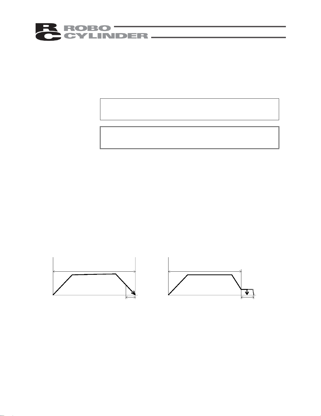
(6) Positioning band
(Pos. band)
The function of the positioning band varies depending on whether the
push & hold setting in (5) is “0” or “other than 0.”
[A] Push = 0 (Positioning mode)
In the positioning mode, enter the position-complete detection width
(distance to the target position), in [mm].
The distance to the target position indicates the range prior to the target
position, upon entry of the actuator in which range a position complete
signal will be output.
The default value is “0.1 [mm]” (Fig. A).
[B] Push = Other than 0 (Push & hold mode)
Enter the maximum push amount (distance from the target) in the push &
hold mode, in [mm] (Fig. B).
If the push direction corresponds to the negative direction along the
displayed coordinate axis, add a – (minus) sign to the entered value.
(A) Push = 0
Distance to the position set in (2)
Speed
Moving distance
Fig. A Fig. B
(B) Push = Other than 0
(6) Positioning band (6) Positioning band
Distance to the position set in (2)
Speed
Moving distance
30
Page 47

(7) Acceleration only MAX
(ACC MAX)
(7) Acceleration only MAX = 0 (7) Acceleration only MAX = 1
Speed
Acceleration/deceleration
set in (4)
Select the specified acceleration or maximum acceleration by entering
“0” or “1.”
The default value is “0.”
0: Specified acceleration --- The value entered in (4) becomes the
actual acceleration/deceleration.
1: Maximum acceleration --- The maximum acceleration set according
to the load is used.
The deceleration conforms to the value
entered in (4).
Moving distance
Maximum acceleration
according to the load
Speed
Acceleration/deceleration
set in (4)
Moving distance
Caution: As a rough guide, enable the acceleration only MAX setting when the actual payload is no more than
one-third of the rated loading capacity.
Check the rated loading capacity of your actuator by referring to the supplied specification list of
supported actuators.
31
Page 48

3.1.1 Push Force at Standstill
In the push & hold mode, enter a current-limiting value (%) in the position-data table under “Push.”
With the RCS, use a push force at standstill corresponding to a current-limiting value of approx. 70%.
The push force at standstill can be increased or decreased by increasing or decreasing the current-limiting value.
However, take note that the controller will not operate properly if the current-limiting value is 30% or below.
The table below lists the push force at standstill for each controller type when the current-limiting value is set to
70%.
Type Motor (W) Speed type
RA35 20
RA45 30
Rod type
Flat type F45 30
RB7525 60
60
RB7530
100
L 95 (9.7)
M 47 (4.8)
H 23 (2.4)
L 142 (14.5)
M 70 (7.2)
H 35 (3.6)
M 143 (14.6)
H 71 (7.3)
L 238 (24.3)
M 118 (12.1)
H 59 (6.1)
M 198 (20.2)
H 99 (10.1)
L 142 (14.5)
M 70 (7.2)
H 35 (3.6)
Push force
(N (kgf))
Note: The accuracy of push force at standstill is not guaranteed. The values are provided for
reference purposes only.
32
Page 49

3.2 Explanation of Modes
3.2.1 Positioning Mode Push = 0
Speed
Position complete signal
Completed position number
Moving OFF
Output
(1) The position complete output will turn
ON and moving output will turn OFF at
a position preceding the target position
by the positioning band. A completed
position number signal will be output at
the same time.
Moving distance
Positioning band
3.2.2 Push & Hold Mode Push = Other than 0
(1) Load was contacted successfully
Speed
Moving distance
Note: The time set in the parameter “Push & hold stop judgment period.” The default value of “255 msec” is
already entered.
The actuator is holding the load in position while pushing it.
The actuator continues to push the load at the push force at standstill determined by the
Warning
current-limiting value. Since the actuator is not inactive, exercise due caution when
handling the machine in this condition.
The push speed is set as follows in accordance with the speed set in the position-data table:
Push speed 20 mm/sec Set speed
Position complete signal
Completed position number
Moving OFF
Output
Positioning band
20 mm/sec or more Less than 20 mm/sec
(1) After reaching the target position, the actuator
will move at low speed.
When the Pos. band set in the data table (see
Note) is reached after the actuator contacts the
load and the servo motor current has reached
the current-limiting value, the position complete
output will turn ON. A completed position
number signal will be output at the same time.
The moving output will turn OFF.
Set speed
33
Page 50

r
f
(2) Load was not contacted (missed)
Speed
Completed position numbe
Moving OFF
Output
Moving distance
Positioning band
(1) After reaching the target position, the
actuator will move at low speed.
Even after contacting the load, the actuator
will move to the end of the positioning band i
the servo motor current is yet to reach the
current-limiting value.
The position complete output will not turn ON
even when the end of the positioning band is
reached. In this case, only the completed
position number will be output. The moving
output will turn OFF.
Check if the load has stopped moving based
on whether the moving output has turned
OFF.
(3) Load moves during push & hold operation
[1] Load moves in the pushed direction
Position complete signal
Completed position number
Speed
Output
Moving OFF
Moving distance
Positioning band
If the load moves in the pushed direction after
the position complete output has turned ON
(moving has turned OFF), the actuator will
push the load within the positioning band.
The moving output will turn ON.
The position complete output will remain ON
and the completed position number will be
output continuously.
Once the load stops moving, the moving
output will turn OFF.
[2] Load moves in the opposite direction from the push force
(Actuator is pushed back by the reactive force of the load)
Position complete signal
Completed position number
Speed
Moving distance
Output
If the actuator is pushed back after the position
complete output has turned ON because the
actuator thrust is smaller than the reactive force of
the load, the actuator will be pushed back all the
way until its thrust balances out with the reactive
force of the load.
The position complete output will remain ON and
the completed position number will be output
continuously.
The moving output will remain ON until the load
stops moving.
34
Page 51

(4) Positioning band was entered with a wrong sign
If the positioning band is entered with a wrong sign,
Speed
the position will deviate by twice the positioning
band, as shown to the left, so exercise due caution.
Moving distance
Positioning
band
Positioning
band
3.2.3 Speed Change during Movement
Speed control involving multiple speed levels is possible in a single operation. The actuator speed can be
decreased or increased at a certain point during movement.
However, the positio n at which to implement each speed change must be set.
Position 1 Position 2 Position 1 Position 2 Position 1 Position 2 Position 3
3.2.4 Operation at Different Acceleration and Deceleration Settings
The actuator will accelerate and decelerate at diff erent speeds if “1” is entered under “Acceleration only MAX” in
the position data.
The acceleration corresponds to the maximum acceleration. The deceleration is the value input in the “Acc/Dec”
field of the position data table.
Caution: Although the specific value differs depending on the actuator, the maximum acceleration cannot be more
than three times the rated acceleration.
Accordingly, this function should be enabled only when the payload is no more than one-third of the rated
loading capacity and the actuator needs to be stopped gradually at slow deceleration.
If this function is enabled when the payload is equivalent to the rated loading capacity, an overload error may
occur.
Even if an overload error does not occur, the actuator will still receive excessive impact loads that may
negatively affect the life of the actuator. Therefore, exercise due caution when enabling this function.
Check the rated loading capacity of your actuator by referring to the supplied specification list of supported
actuators.
Speed
Maximum acceleration
according to the load
Time
Deceleration can be set
freely
35
Page 52

3.2.5 Pause
This signal can be used to stop the actuator in case of emergency.
The movement of the actuator can be paused via an external input signal (pause).
For safety reasons, this signal is provided as a contact-b input (based on the negative logic).
The actuator will decelerate to a stop when the pause input is turned OFF, and resume movement when the
pause input is turned ON.
Pause signal
Actuator operation
The remaining movement of the actuator can be cancelled by turning ON the reset input during pause (the
movement will be cancelled upon rise of the reset input signal).
Pause signal
Reset
Actuator operation
3.2.6 Zone Signal Output
This signal is output while the actuator is moving inside a specified zone (the zone can be set in a desired
position).
By setting a zone signal in the applicable parameter beforehand, you can cause the zone signal to turn ON when
the actuator enters the specified zone (the zone can be set in any position, even at the center of the stroke).
Zone signal ON
36
Zone signal setting range
Page 53

3.2.7 Home Return
With the standard specification, home return must be performed after the power has been input or an encoder
open or CPU error alarm has been reset. Selecting a position number and then initiating a start will cause the
controller to automatically perform home return before commencing the subsequ e nt operation. Once home return
is complete, the home return completion output will turn ON (standard specification).
Home return alone cannot be performed using PIO. To move the actuator to the home position in a normal
condition, set a position number for which “0” is set in the position-dat a table under “Position,” and then issue a
movement command to that position.
With the absolute specification, home return is not necessary after the power has been input, as long as an
absolute reset was performed once.
3.3 Timing Chart
Start
Command position
Position complete
Completed position
Moving
*Pause
Acc/dec Description
T1 Start ON minimum duration
T2 Start OFF minimum duration
T3
T4
T5
T6
T7
T8
T9
T10
*1: The maximum value will vary depending on the acceleration/deceleration.
*2: After the position complete signal turned ON, wait for at least the sequencer’s scan time before checking the
Start ON Command position hold time
Start ON Position complete OFF delay
Position complete OFF Moving ON delay
Pause OFF Moving OFF delay
Pause ON Moving ON delay
Position complete ON Moving OFF delay
Completed position OFF Position complete OFF delay
Position complete ON Completed position output delay
completed position.
Minimum Maximum
4 msec
4 msec
6 msec
0.1 msec 1 msec
0.1 msec
7 msec
1 msec
*1
6 msec
2 msec
1 msec
*2
37
Page 54

4. Using the Controller <Practical Steps>
4.1 How to Start (Standard Type)
(Refer to 4.2, “How to Execute An Absolute Reset,” for the absolute specification.)
(1) Confirm that both Nos. 5 and 6 of piano switch are set to OFF. If these switches are set to ON, tilt them back
to the OFF positions.
(2) Connect the motor/brake cables and encoder cable to the controller.
(3) Connect the host PLC to the PIO connector using the supplied flat cable.
(4) If two or more axes are connected, set the necessary items using the piano switches. For details, refer to
“Names and Functions of Parts.”
(5) Supply the main power to the controller’s terminal block.
Turn ON the pause and servo ON inputs at the PIO connector.
(6)
(7) The controller is working properly if the RDY LED is lit. If the ALM LED is lit, there is an error. Refer to the
alarm table and take an appropriate action.
Note: PIO inputs/outputs must be issued after the position complete signal turns ON following the
power ON.
The controller is ready once the above operation is completed.
4.1.1 When the Controller Can/Cannot Operate
(1) The moment the power is turned on, the servo turns on. When the controller becomes ready, the PIO
position complete output will turn ON.
(2) The following chart shows the timing relationships of the PIO alarm/emergency-stop outputs and controller’s
operating status.
Emergency stop
Alarm
Reset
Controller
can operate
Emergency-stop
switch is pressed.
Controller
cannot operate
Controller
can operate
Alarm occurs.
Controller
cannot operate
Controller
can operate
38
Page 55

4.2 How to Execute Absolute Reset (Absolute Specification)
Note) With the absolute specification, 0E5 (an encoder receive error) will occur when the power is turned on for
the first time after the battery or PG cable was disconnected. This does not indicate fault. If this error
occurs, execute an absolute reset by following the specified procedure.
The specific method to execute an absolute reset will vary depending on the controller version.
A label on which a serial number is printed is attached on the right side of the controller.
In the serial number, check the alphabet in the second digit from the last.
Example) SERIAL No. AD251031 J3
In this example, the controller version is “J.”
An absolute reset is executed in different ways on cont rollers of version J* or earlier (A* to J*) and controllers of
version K* or later (K*, L*, etc.) (* indicates a number).
(If the controller version is K* or later, perform home return from the teaching pendant or PC software when
executing an absolute reset.)
How to Execute an Absolute Reset on a SERIAL No. K* or Later
[1] Connect the motor cable and encoder/brake cables to the controller.
[2] Connect the host PLC to the PIO connector using the supplied flat cable.
[3] If two or more axes are connected using a controller link cable, set the address using the piano switches
(SW) on the controller. For details, refer to 2.2, “Names and Functions of Parts,” in this manual .
[4] Connect the battery to the controller.
[5] Turn ON piano switch (SW) No. 5 (fifth from the bottom) on the controller (by tilting it to the right).
[6] Turn on the main controller power.
[7] The ALM LED will illuminate.
[8] Turn ON the pause and servo ON input signals at the PIO connector.
[9] Input a reset signal via the PIO connector to reset the alarm.
[10] Perform home return from the teaching pendant or PC software.
[11] Turn switch No. 1 of the controller’s piano switches 2 (SW2) to OFF (tilt to the left).
An absolute reset has been executed.
39
Page 56

How to Execute an Absolute Reset on a a SERIAL No. J* or Earlier
[1] Connect the motor and encoder/brake cables to the controller.
[2] Connect the host PLC to the PIO connector using the supplied flat cable.
[3] If two or more axes are connected, set the address using SW1 on the controller. For details, refer to “Names
and Functions of Parts.”
[4] Move the actuator slider or rod to a position whe re it is in contact with the mechanical end on the home side.
[5] Turn ON piano switch (SW) No. 5 on the controller (by tilting it to the right).
[6] Turn on the main controller power.
[7] The RDY LED will illuminate.
[8] Turn OFF piano switch No. 5 on the controller.
[9] Turn switch No. 1 of the controller’s SW2 to OFF (tilt to the left). Note 1)
An absolute reset has been executed. The home has been set several millimeters ahead of the current
position (mechanical end) (the specific distance from the mechanical end will vary depending on the actuator
model).
[10] To operate the actuator right away, turn ON the PIO pause/servo ON inputs.
Note 1) If switch No. 5 of piano switch remains ON, the next time the power is turned on an absolute reset will
be executed based on the actuator position at that time.
Note 1) The absolute RCS controller can be used only with absolute RCS actuators. It cannot be used
with standard RCS actuators.
40
Page 57

4.3 Movement after Power On (Standard Type)
Example of use in operation) After the power is turned on, move the actuator to the position 150 mm from the
No. Position Speed
0 0 100 0.3 0 0.1 0
1 150 200 0.3 0 0.1 0
P
L
C
[7] [4]
[3]
[2]
[1]
[10]
[9] [5]
[8]
[11] [6]
Signal name
Start
Command position 1
Command position 2
Command position 4
Command position 8
Pause
Reset
Servo ON
Completed position 1
Completed position 2
Completed position 4
Completed position 8
Position complete
Home return completion
Zone
Alarm
Emergency stop
Moving
With the absolute specification, the home
return completion signal will turn ON after
the power is turned on, and the actuator will
move directly to position 1 without
performing home return.
home at a speed of 200 mm/sec.
Position-data table (Field(s) within thick line must be entered.)
Acceleration/
deceleration
Push Positioning band
RCS controller
PIO
Reference flow
Power ON
Category
Servo ON input ON
[1]
Pause input ON
[2]
Select/enter command position 1.
Input
Output
[3]
Start input ON
[4]
Home return starts.
Position complete output OFF
[5]
Moving output ON
[6]
Start input OFF
[7]
Home return completes.
Home return completion output ON
[8]
Movement to position 1 starts.
Position complete output turns ON 0.1 mm
[9]
before position 1.
[10]
Completed position 1 is output.
Moving output OFF
[11]
Movement to position 1 completes.
Acceleration
only MAX
41
Page 58

Command position
Power ON
Servo ON
Start
Position 1
Note
Position complete
Emergency stop
Completed position
* Home return
*Actuator movement
Pause
Alarm
completion
Speed
Moving
Position 1
Positioning band
Time
The position complete output will turn ON when the controller becomes ready following the po wer ON. (The
position complete output will not turn ON if the servo ON input is OFF.)
To check if the controller is ready, always check if the position complete output is ON.
All completed position outputs are OFF immediately after the po wer is turned on. When the commanded
movement is complete, the completed position will be output. If the movement command was to position No. 0, all
of the completed positions will remain OFF.
The actuator will not operate unless the pause input is turned ON.
T1: 5 msec or m ore; time after selecting/entering a command position until the start input turns ON
(The scan time of the host controller must be considered.)
* With the absolute specification, the home return completion signal will turn ON after the power is turned on, and
home return will not be performed.
Note: When the start signal turns ON, the position complete output will turn OFF and the moving
output will turn ON.
The start signal must be turned OFF with the confirmation that the moving output has turned
ON while the start signal remains ON.
If the start input remains ON as shown below , the position complete output will not turn ON even
when the actuator movement is completed. The moving output will not turn OFF, either.
Position complete
Start
Moving
1 msec or less
Actuator
42
Page 59

4.4 Positioning Mode (Back and Forth Movement between Two Points)
Example of use in operation) The actuator moves back and forth between two positions. The position 250 mm
from the home is set as position 1, and the position 100 mm from the home is set
as position 2. The travel speed to position 1 is set as 200 mm/sec, and to position 2
P
L
C
[13] [10] [5] [2]
[1]
[9]
[7]
[15]
[14] [11] [6] [3]
[16] [12] [8] [4]
Signal name
Start
Command position 1
Command position 2
Command position 4
Command position 8
Pause
Reset
Servo ON
Completed position 1
Completed position 2
Completed position 4
Completed position 8
Position complete
Home return completion
Zone
Alarm
Emergency stop
Moving
is set as 100 mm/sec.
PIO
Category
Input
Output
RCS controller
Reference flow
Select/enter command position 1.
[1]
[2]
Start input ON
Movement to position 1 starts.
Completed position OFF
[3]
Position complete output OFF
[4]
Moving output ON
[5]
Start input OFF
Position complete output ON
[6]
[7]
Completed position 1 is output.
Moving output OFF
[8]
[9]
Select/enter command position 2.
Movement to position 1 completes.
Start input ON
[10]
Movement to position 2 starts.
Completed position OFF
[11]
Position complete output OFF
Moving output ON
[12]
Start input OFF
[13]
[14]
Position complete output ON
Completed position 2 is output.
[15]
Moving output OFF
[16]
Movement to position 2 completes.
43
Page 60

No. Position Speed
0 * * * * * *
1 250 200 0.3 0 0.1 0
2 100 100 0.3 0 0.1 0
Position-data table (Field(s) within thick line must be entered.)
Acceleration/
deceleration
Push Positioning band
Acceleration
only MAX
Command position
Position complete
Moving
Completed position
Actuator movement
Start
Speed
Position 1 Position 2 Position 1
Note Note Note
Position 1 Position 2 Position 1
T1: 5 msec or m ore; time after selecting/entering a command position until the start input turns ON
(The scan time of the host controller must be considered.)
Each command position must be input after the position complete output has turned ON for the movement to the
previous position.
Note: When the start signal turns ON, the position complete output will turn OFF and the moving
output will turn ON.
The start signal must be turned OFF with the confirmation that the moving output has turned
ON while the start signal remains ON.
If the start input remains ON as shown below, the position complete output will not turn ON even
when the actuator movement is completed. The moving output will not turn OFF, either.
Position complete
Start
Moving
Actuator
1 msec or less
44
Page 61

4.5 Push & Hold Mode
Example of use in operation) The actuator is caused to move back and forth in the push & hold mode and positioning
mode. The position 280 mm from the home is set as position 1, and the position 40 mm
from the home is set as position 2.
Movement to position 1 is performed in the push & hold mode (the actuator is caused to
contact the load and push it in the counter-motor direction). The maximum push amount
at position 1 is set as 15 mm, and the current-limiting value during the push & hold
operation by the servo motor is set as 50%. Movement to position 2 is performed in the
positioning mode. The travel speed to position 1 is set as 200 mm/sec, and that to
P
L
C
[13] [10] [5] [2]
[1]
[9]
[7]
[15]
[14] [11] [6] [3]
[16] [12] [8] [4]
Signal name
Start
Command position 1
Command position 2
Command position 4
Command position 8
Pause
Reset
Servo ON
Completed position 1
Completed position 2
Completed position 4
Completed position 8
Position complete
Home return completion
Zone
Alarm
Emergency stop
Moving
position 2 is set as 100 mm/sec.
RCS controller
PIO
Category
Input
Output
Reference flow
Select/enter command position 1.
[1]
Start input ON
[2]
Movement to position 1 starts.
Completed position OFF
[3]
Position complete output OFF
[4]
Moving output ON
Start input OFF
[5]
Move at slow speed after passing position 1.
Load is pushed. Servo motor current rises to
the current-limiting value.
[6]
Position complete output ON
Completed position 1 is output.
[7]
Moving output OFF
[8]
Select/enter command position 2.
[9]
Start input ON
[10]
Movement to position 2 starts.
Completed position OFF
[11]
Position complete output OFF
Moving output ON
[12]
Start input OFF
[13]
Position complete output turns ON 0.1 mm
[14]
before position 2.
Completed position 2 is output.
[15]
Moving output OFF
[16]
Movement to position 2 completes.
45
Page 62

No. Position Speed
0 * * * * * *
1 280 200 0.3 50 15 0
2 40 100 0.3 0 0.1 0
Position-data table (Field(s) within thick line must be entered.)
Acceleration/
deceleration
Push Positioning band
Acceleration
only MAX
Command position
Position complete
Moving
Completed position
Actuator movement
Start
Speed
Position 1 Position 2 Position 1
Note Note Note
Position 1 Position 2 Position 1
T1: 5 msec or m ore; time after selecting/entering a command position until the start input turns ON
(The scan time of the host controller must be considered.)
Each command position must be input after the position complete output has turned ON for the movement to the
previous position.
Note: When the start signal turns ON, the position complete output will turn OFF and the moving
output will turn ON.
The start signal must be turned OFF with the confirmation that the moving output has turned
ON while the start signal remains ON.
If the actuator has missed the load, the position complete output will not turn ON as shown
below. The completed position will be output and the moving output will turn OFF.
Command position
Position complete
Completed position
Actuator movement
Start
Moving
Speed
Position 1 Position 2 Position 1
Position 1 Position 2 Position 1
46
Page 63

4.6 Speed Change during Movement
Example of use in operation) The actuator speed is reduced at a certain point during movement.
The position 150 mm from the home is set as position 1, and the position 200 mm from
the home is set as position 2. The actuator is initially located between the home and
position 1. The actuator is moved to position 2 being the target position, at a travel
speed of 200 mm/sec to position 1 and that of 100 mm/sec from position 1 to position 2.
Method) In this example, the actuator is caused to move to position 1 and to position 2
successively . Before the actuator is stopped at position 1, command position 2 must be
selected/entered and the start signal must be input. To do this, set a wide positioning
band at position 1 and cause the start signal for movement to position 2 to be input
immediately after the completion signal for movement to position 1 is output. (Command
P
L
C
[11] [9] [5] [2]
[1]
[6]
[8]
[13]
[12] [10] [7] [3]
[14] [4]
Signal name
Start
Command position 1
Command position 2
Command position 4
Command position 8
Pause
Reset
Servo ON
Completed position 1
Completed position 2
Completed position 4
Completed position 8
Position complete
Home return completion
Zone
Alarm
Emergency stop
Moving
position 2 should be entered while the actuator is moving to position 1.)
RCS controller
PIO
Category
Reference flow
Select/enter command position 1.
[1]
Start input ON
[2]
Movement to position 1 starts at 200 mm/sec.
Completed position OFF
Position complete output OFF
Input
Output
[3]
Moving output ON
[4]
Start input OFF
[5]
Select/enter command position 2.
[6]
Position complete output turns ON 1
[7]
mm before position 1.
Completed position 1 is output.
[8]
Start input ON
[9]
Movement to position 2 starts at 100 mm/sec.
Completed position OFF
Position complete output OFF
[10]
[11]
[12]
[13]
[14]
Start input OFF
Position complete output turns ON
0.1 mm before position 2.
*
Completed position 2 is output.
Moving output OFF
Movement to position 2 completes.
47
Page 64

No. Position Speed
0 * * * * * *
1 150 200 0.3 0 1 0
2 200 100 0.3 0 0.1 0
Position-data table (Field(s) within thick line must be entered.)
Acceleration/
deceleration
Push Positioning band
Acceleration
only MAX
Command position
Position complete
Completed position
Actuator movement
Start
Moving
Speed
Position 1 Position 2
Note Note
Position 2
Position 1
T1: 5 msec or m ore; time after selecting/entering a command position until the start input turns ON
(The scan time of the host controller must be considered.)
Note: When the start signal turns ON, the position complete output will turn OFF and the moving
output will turn ON.
The start signal must be turned OFF with the confirmation that the moving output has turned
ON while the start signal remains ON.
48
Page 65

4.7 Operation at Different Acceleration and Deceleration Settings
Example of use in operation) Positioning is performed to the position 150 mm from the home (position 1) at a
speed of 200 mm/sec. The actuator will accelerate at the maximum acceleration
set according to the load, and decelerate at 0.1 G.
Method) Entering “1” under “Acceleration only MAX” in the position data will automatically
adjust the acceleration to the maximum acceleration set according to the load.
Entering “0.1” under “Acceleration/deceleration” in the position data will set the
P
L
C
[5] [2]
[1]
[7]
[6] [3]
[8] [4]
Signal name
Start
Command position 1
Command position 2
Command position 4
Command position 8
Pause
Reset
Servo ON
Completed position 1
Completed position 2
Completed position 4
Completed position 8
Position complete
Home return completion
Zone
Alarm
Emergency stop
Moving
deceleration to 0.1 G.
PIO
Category
Input
Output
RCS controller
[1]
[2]
[3]
[4]
[5]
[6]
[7]
[8]
Reference flow
Select/enter command position 1.
Start input ON
Movement to position 1 starts at the maximum
acceleration.
Completed position OFF
Position complete output OFF
Moving output ON
Start input OFF
Moves at constant speed (200 mm/sec).
Decelerates at 0.1 G.
Position complete output turns ON
0.1 mm before position 1.
Completed position 1 is output.
Moving output OFF
Movement to position 1 completes.
49
Page 66

No. Position Speed
0 * * * * * *
1 150 200 0.1 0 0.1 1
Position-data table (Field(s) within thick line must be entered.)
Acceleration/
deceleration
Push Positioning band
Acceleration
only MAX
Command position
Start
Position complete
Completed position
Moving
Speed
Actuator movement
Position 1
Position 1
Positioning band
T1: 5 msec or m ore; time after selecting/entering a command position until the start input turns ON
(The scan time of the host controller must be considered.)
Note: When the start signal turns ON, the position complete output will turn OFF and the moving
output will turn ON.
The start signal must be turned OFF with the confirmation that the moving output has turned
ON while the start signal remains ON.
If the start input remains ON as shown below, the position complete output will not turn ON even
when the actuator movement is completed. The moving output will not turn OFF, either.
Position complete
Start
Moving
Actuator
1 msec or less
50
Page 67

4.8 Pause
Example of use in operation) The actuator is paused duri ng movement.
Method) Use the pause input.
RCS controller
P
L
C
[5] [2]
[1]
[8] [6]
[11]
[10] [3]
[12] [9] [7] [4]
Signal name
Start
Command position 1
Command position 2
Command position 4
Command position 8
Pause
Reset
Servo ON
Completed position 1
Completed position 2
Completed position 4
Completed position 8
Position complete
Home return completion
Zone
Alarm
Emergency stop
Moving
PIO
Category
Input
Output
Reference flow
Select/enter a desired command position.
[1]
Start input ON
[2]
Movement to the selected position starts.
Completed position OFF
Position complete output OFF
[3]
Moving output ON
[4]
Start input OFF
[5]
Pause input OFF (Actuator
[6]
decelerates to a stop.)
Moving output OFF
[7]
Pause input ON (Movement starts.)
[8]
Moving output ON
[9]
Position complete output ON
[10]
Completed position is output.
[11]
Moving output OFF
[12]
Movement to the selected position
completes.
51
Page 68

Command position
Position complete
Completed position
Actuator movement
Start
Pause
Moving
Speed
Note
4 msec or less
T1: 5 msec or m ore; time after selecting/entering a command position until the start input turns ON
(The scan time of the host controller must be considered.)
Note: When the start signal turns ON, the position complete output will turn OFF and the moving
output will turn ON.
The start signal must be turned OFF with the confirmation that the moving output has turned
ON while the start signal remains ON.
The remaining movement can be cancelled by turning ON the reset input during pause.
(The controller will detect a rise of the reset signal and cancel the remaining movement.)
52
Command position
Start
Position complete
Completed position
Pause
Reset
Moving
Speed
Actuator movement
4 msec or more
Page 69

A
4.9 Zone Signal Output
Example of use in operation) While the actuator is moving a zone signal is output inside the zone enclosed by
distances of 40 mm and 120 mm from the home. (40 mm Zone signal output
120 mm)
Method) Use the parameters “Zone boundary+” and “Zone boundary–” to set the zone in
P
L
C
[5] [2]
[1]
[9]
[8] [3]
[7] [6]
[10] [4]
Signal name
Start
Command position 1
Command position 2
Command position 4
Command position 8
Pause
Reset
Servo ON
Completed position 1
Completed position 2
Completed position 4
Completed position 8
Position complete
Home return completion
Zone
Alarm
Emergency stop
Moving
which the zone signal is output, as shown below:
Zone boundary+ 120
Zone boundary– 40
RCS controller
PIO
Category
Input
Output
Reference flow
Select/enter a desired command position.
[1]
Start input ON
[2]
Movement to the selected position starts.
Completed position OFF
Position complete output OFF
[3]
Moving output ON
[4]
Start input OFF
[5]
Actuator enters the zone. Zone output ON
[6]
[7]
[8]
[9]
ctuator exits the zone. Zone output
OFF
Position complete output ON
Completed position is output.
Moving output OFF
[10]
Movement to the selected position
completes.
53
Page 70

Command position
Position complete
Completed position
Actuator movement
Moving
Start
Zone
Speed
Note
T1: 5 msec or m ore; time after selecting/entering a command position until the start input turns ON
(The scan time of the host controller must be considered.)
Note: When the start signal turns ON, the position complete output will turn OFF and the moving
output will turn ON.
The start signal must be turned OFF with the confirmation that the moving output has turned
ON while the start signal remains ON.
Example of other zone output)
Zone output at 120 or more Zone output at 40 or less
Zone
Zone
Zone boundary+ Maximum stroke length Zone boundary+ 40
Zone boundary– 120 Zone boundary– 0
54
Page 71

4.10 Returning Home
Example of use in operation) Home return alone cannot be performed using PIO.
Method) Create point data of 0 distance from the home, and move the actuator to that
position.
Enter home data in position 0. To return home, move the actuator to position 0.
Position-data table (Field(s) within thick line must be entered.)
No. Position Speed
0 0 100 0.3 0 0.1 0
1 * * * * * *
Acceleration/
deceleration
P
L
C
[5] [2]
[1]
[6] [3]
[7] [4]
Signal name
Start
Command position 1
Command position 2
Command position 4
Command position 8
Pause
Reset
Servo ON
Completed position 1
Completed position 2
Completed position 4
Completed position 8
Position complete
Home return completion
Zone
Alarm
Emergency stop
Moving
PIO
Category
Input
Output
Push Positioning band
RCS controller
[1]
[2]
[3]
[4]
[5]
[6]
[7]
Acceleration
only MAX
Reference flow
Select/enter a desired command
position. (Command positions 1, 2, 4
and 8 are all OFF)
Start input ON
Movement to position 0 (home) starts.
Completed position OFF
Position complete output OFF
Moving output ON
Start input OFF
Position complete output turns ON 0.1 mm
before position 0.
Moving output OFF
Movement to position 0 completes.
55
Page 72

Command position
Start
Position complete
Completed position
Moving
Speed
Actuator movement
Position 0
Note
Turn all of command positions
1, 2, 4 and 8 OFF.
Completed positions 1,
2, 4 and 8 all turn OFF.
T1: 5 msec or m ore; time after selecting/entering a command position until the start input turns ON
(The scan time of the host controller must be considered.)
Data of 0 distance from the home need not be always entered in position 0.
In this example, data of 0 distance from the home was entered in position 0. Of course, su ch data can also be
entered in any other position of 1 to 15.
Note: When the start signal turns ON, the position complete output will turn OFF and the moving
output will turn ON.
The start signal must be turned OFF with the confirmation that the moving output has turned
ON while the start signal remains ON.
If the start input remains ON as shown below, the position complete output will not turn ON even
when the actuator movement is completed. The moving output will not turn OFF, either.
Position complete
Start
Moving
Actuator
1 msec or less
56
Page 73

4.11 Incremental Moves
Example of use in operation) The actuator is caused to move from the home to the 30-mm position, from which it will
be moved repeatedly in increments of 10 mm. The travel speed from the home to the
30-mm position is set as 100 mm/sec, and that for 10-mm incremental moves is set as
P
L
C
[13] [10] [5] [2]
[1]
[9]
[7]
[15]
[14] [11] [6] [3]
[16] [12] [8] [4]
Signal name
Start
Command position 1
Command position 2
Command position 4
Command position 8
Pause
Reset
Servo ON
Completed position 1
Completed position 2
Completed position 4
Completed position 8
Position complete
Home return completion
Zone
Alarm
Emergency stop
Moving
20 mm/sec.
PIO
RCS controller
Category
Input
Output
Reference flow
Select/enter command position 1.
[1]
Start input ON
[2]
Movement to position 1 starts.
Completed position OFF
[3]
Position complete output OFF
Moving output ON
[4]
Start input OFF
[5]
Position complete output ON
[6]
Completed position 1 is output.
[7]
Moving output OFF
[8]
Movement to position 1 completes.
Select/enter command position 2.
[9]
Start input ON
[10]
Movement to +10 mm from the current position starts.
Completed position OFF
Position complete output OFF
[11]
[12]
Moving output ON
[13]
Start input OFF
Position complete output ON
[14]
Completed position 2 is output.
[15]
Moving output OFF
[16]
57
Page 74

No. Position Speed
0 * * * * * *
1 30 100 0.3 0 0.1 0
2
=
10 20 0.3 0 0.1 0
Position-data table (Field(s) within thick line must be entered.)
Acceleration/
deceleration
Push Positioning band
Acceleration
only MAX
Command position
Position complete
Completed position
Actuator movement
Start
Moving
Speed
Position 1 Position 2
Note 1
Note 2
Position 1 Position 2 Position 2
Time
Distance from home
T1: 5 msec or m ore; time after selecting/entering a command position until the start input turns ON
(The scan time of the host controller must be considered.)
Note 1: When the start signal turns ON, the position complete output will turn OFF and the moving
output will turn ON.
The start signal must be turned OFF with the confirmation that the moving output has turned
ON while the start signal remains ON.
If the start input remains ON as shown below, the position complete output will not turn ON even
when the actuator movement is completed. The moving output will not turn OFF, either.
Position complete
Start
Moving
Actuator
1 msec or less
Note 2: When a soft limit is reached as a result of repeated incremental moves, the actuator will stop
at that position and the position complete signal will be output.
58
Page 75

4.12 Notes on Incremental Mode
(1) Notes on positioning operation
Selecting/entering a position number using relative coordinates during positioning will cause the actuator to
move to the position corresponding to the initial position plus the increment. (If the increment is a negative
value, the actuator will move to the position corresponding to the initial position minus the increment.)
Example) If the start signal for movement to position 2 is input while the actuator is moving to position 1,
the actuator will move to the position 40 mm from the home.
Command position
Position 1 Position 2
Start
Position complete
Completed position
Moving
Actuator movement
If the start signal for movement to an incremental position numbe r is input multiple times during positioning,
the actuator will move to the position corresponding to the initial position plus the “increment x number of
times the signal was input.”
Example) If the start signal for movement to position 2 is input twice while the actuator is moving to
Command position
Position complete
Completed position
Actuator movement
Moving
(2) Note on push & hold operation
If the start signal is input with an incremental position number selected/entered while the actuator is moving
in the push & hold mode, the actuator will move to the position corresponding to the position at the time of
start input plus the increment. Therefore, the end position will become indeterminate.
Speed
Position from home: 40
position 1, the actuator will move to the position 50 mm from the home.
Position 1 Position 2
Start
Speed
Position from home: 50
Position 2
Distance
Position 2
Distance
No. Position Speed
0 * *
1 30 100
2
10 100
=
59
Page 76

Example) If the start signal for movement to position 2 is input while the actuator is moving to position 1 in
the push & hold mode, the actuator will move to the position 10 mm from where it was when the
input signal was input.
Command position
Position complete
Completed position
Actuator movement
Start
Speed
Position 1 Position 2
10 mm
Position 2
Distance
No. Position Speed
0 * *
1 50 100
2
10 100
=
(3) Cumulative errors due to repeated incremental moves
Position data is recognized only as a multiple of the minimum resolution. The minimum resolution is
determined by the lead and the number of encoder pulses. Therefore, a margin of error may occur between
the entered position value and the actual movement of the actuator. If an incremental move is repeated, this
error will accumulate.
The maximum error range for each actuator type is shown below:
Type
SA4 20
Slider
type
type
Flat
SA5 20
SA6 30
F45 30
Motor
(W)
Speed
type
M 5 0.3 M 5 0.6
H 10 0.6
M 6 0.4 M 5 0.3
H 12 0.7
M 6 0.4
H 12 0.7
M 5 0.3
H 10 0.6
Screw
lead (mm)
L 2.5 0.2 L 2.5 0.3
L 3 0.2 L 2.5 0.2
L 3 0.2 M 5 1.6
L 2.5 0.2
Maximum
error ()
Type
RA35 20
Rod
type
RA45 30
RB7525 60
Motor
(W)
Speed
type
H 10 1.2
H 10 0.6
H 10 3.3
Screw
lead (mm)
Maximum
error ()
60
Page 77

5. Parameters
5.1 Parameter Classification
The parameters are classified into the following four types depending on their function:
Types:
a: Parameter relating to actuator stroke range
b: Parameter relating to actuator operating characteristics
c: Parameter relating to external interface
d: Servo gain adjustment
5.2 Parameter List
No. Type Name Unit Factory default
1 a Zone limit + side mm Effective actuator length
2 a Zone limit – side mm Effective actuator length
3 a Soft limit + side mm Effective actuator length
4 a Soft limit – side mm Effective actuator length
5 a Home direction [0: Reverse/1: Forward] - (In accordance with the ordered specification.)
6 b Push & hold recognition time msec 255
7 d Servo gain No. 8 b Initial speed setting
9 b Initial acceleration/deceleration setting G
10 b Initial positioning band (in-position) mm 0.10
11 b Initial acceleration only MAX flag - 0
12 b Current limit value during positioning stop %
13 b Current limit value during homing %
14 b Movement flag during stop - 1
15 c
16 c Serial communication speed bps 38400
17 c
18 Reserved -
19 Reserved -
20 Reserved -
21 c
22 a Home offset mm
Hold input disable selection [0: Enable/1:
Disable]
Minimum delay before slave transmitter
activation
Servo ON input disable selection [0:
Enable/1: Disable]
mm/sec Set individually depending on the actuator characteristics.
msec 5
(Note) The numbers are shown on the PC software screen, but not on the teaching pendant.
The type symbols are given for convenience and not shown on the PC software screen or teaching pendant.
Set individually depending on the actuator characteristics.
Set individually depending on the actuator characteristics.
Set individually depending on the actuator characteristics.
Set individually depending on the actuator characteristics.
- 0
- 0
Set individually depending on the actuator characteristics.
61
Page 78

5.3 Parameter Settings
If you have changed any parameter, be sure to restart the controller via a softwa re reset or reconnect the
controller power.
5.3.1 Parameters Relating to Actuator Stroke Range
Soft limits
Set the + soft limit in parameter No. 3 and – soft limit in parameter No. 4.
Both parameters have been set to the effective actuator length at the factory. Change the parameter settings if
necessary, such as when an obstacle is present and collision between the actuator and obstacle must be
prevented or when the actuator must be operated beyond the effective length.
Exercise due caution when setting these parameters, as wrong settings will cause collision with the mechanical
end.
The minimum setting unit is 0.01 mm.
(Note) To change these parameters, set values corresponding to positions that are 0.3 mm wider than the
desired effective range.
Example) Set the effective range to between 0 and 80 mm
Parameter No. 3 (+ side): 80.3
Parameter No. 4 (– side): -0.3
Approximately
0.3 mm
Approximately
0.1 mm
Soft limit set in the controller
Effective territory
Approximately
JogIncrement movable range upon homing
Zone limits
Set the zone in which the zone output signal turns ON.
The zone signal will turn ON when the current coordinate is between the – setting and + setting.
Set the + zone limit in parameter No. 1 and – zone limit in parameter No. 2.
The minimum setting unit is 0.01 mm.
Example) With the actuator of 300-mm stroke, use the zone limits as an intermediate LS actuating in a range of
100 to 200 mm
Parameter No. 1 (+ side): 200 Parameter No. 2 (– side): 100
(Home)
Zone output turns ON.
Home direction
If not specified by the user, the home direction is set to the motor side before shipment.
If you must change the home direction after the actuator has been assembled to your equipment, switch 0 and 1
in the setting of parameter No. 5.
If necessary, also change the home offset and soft limits.
Caution: Rod-type actuators do not permit reversing of the home direction.
If the home direction is reversed, all position data currently input will be cleared.
Approximately
0.3 mm
0.1 mm
62
Page 79

Home offset
Parameter No. 22 has been set to an optimal value at the factory so that the distance from th e mechanical end to
home will remain constant.
The minimum setting unit is 0.01 mm.
This parameter can be adjusted in the following cond itions:
[1] Align the actuator’s home with the mechanical home on the equipment after the actuator has been
assembled to the equipment.
[2] Set the home position again after reversing the factory-set ho me direction.
[3] Correct the minor position deviation that has generated after the actuator was replaced.
Caution: If you have changed the home offset, the soft limit parameters must also be reviewed.
5.3.2 Parameters Relating to Actuator Operating Characteristics
Initial speed setting
This parameter has been set to the rated speed of the actuator at the factory.
If a target position was written to an unregistered position table or the current position was acquired in the
teaching mode, the controller regards the value of this parameter as the speed data corresponding to the
applicable position number.
To set a speed lower than the rated speed, change the setting of parameter No. 8.
Initial acceleration/deceleration setting
This parameter has been set to the rated acceleration/deceleration of the actuator at the factory.
If a target position was written to an unregistered position table or the current position was acquired in the
teaching mode, the controller regards the value of this parameter as the acceleration/decel eration data
corresponding to the applicable position number.
To set an acceleration/deceleration lower than the rated acceleration/deceleration, change the setting of
parameter No. 9.
Initial positioning band (in-position)
This parameter has been set to “0.10” mm at the factory.
If a target position was written to an unregistered position table or the current position was acquired in the
teaching mode, the controller regards the value of this parameter as the positioning band data corresponding to
the applicable position number.
Since increasing this value will cause a position complete signal to output early, change the setting of parameter
No. 10 as necessary.
Initial acceleration only MAX flag
To cause the actuator to stop gradually at slow deceleration, you must set a lower acceleration/deceleration.
However, this will also slow the acceleration.
This parameter lets you set a quicker acceleration without affecting the deceleration.
Note, however, that this parameter can be used only when the actual payload is no more than one-third of the
rated loading capacity.
Check the rated loading capacity of your actuator by referring to the supplied specification list of supported
actuators.
This parameter has been set to “0” (Disable) at the factory.
If a target position was written to an unregistered position table or the current position was acquired in the
teaching mode, the controller regards the value of this parameter as the “acceleration only MAX” dat a
corresponding to the applicable position number.
To enable this function, change parameter No. 11 to “1” (Enable).
63
Page 80

Push & hold recognition time
This parameter is used as a condition for determining if the actuator has contacte d the work part and completed
its push-mode operation.
Specifically, push-mode operation is deemed complete if the current limit value set in the position table has been
maintained for the time set in parameter No. 6.
Set this parameter to an optimal value in accordance with the current limit value, by considering the shape and
strength of the work part, etc.
The minimum setting unit is 1 msec, and the maximum value is 255 msec. This parameter has been set to “255”
msec at the factory.
(Note) If the work part has shifted and current has changed during the push & hold re cognition time, the
judgment will be made as follows. In this example, the push & hold recognition time is set to 255 msec.
Push current
Start position Target position Counting starts
Count to 200
Decrement to 180
Count to 255
Completion of push-mode operation is recognized.
If the push current is maintained for 200 msec and then drops for 20 msec thereafter, the counter is decremented
by 20. Upon recovery of the push current, counting resumes from 180. If the push current is maintained for 75
msec, the counter will have counted up to 255 and thus the controller will recognize completion of push-mode
operation.
In this case, the judgment requires a total of 295 msec.
Current limit value during positioning stop
At the factory, this parameter has been set to a current value corresponding to the standard specification of the
actuator.
Increasing this value will increase the holding torque while the actuator is stoppe d.
This parameter need not be changed in normal conditions of u se. Howeve r, hunting will occur if excessive
external force applies to the actuator while the actuator is stopped. In this case, the value set in parameter No. 12
must be increased.
If you need to change this parameter, please contact IAI first.
Current limit value during homing
At the factory, this parameter has been set to a current value corresponding to the standard specification of the
actuator.
Increasing this value will increase the torque during homing.
This parameter need not be changed in normal conditions of u se. Howeve r, the value set in parameter No. 13
must be increased if the slide resistance has increased in a vertical application due to the affixing method, load
condition, etc., and homing completes before the correct position.
If you wish to change this parameter, please contact IAI first.
64
Page 81

Movement flag during stop
This parameter defines whether to enable or disable the dynamic brake while the actuator is stopped.
It has been set to “1” (Enable) at the factory.
This parameter need not be changed in normal condit ions of use, but there are situations whe re the actuator must
be moved by hand with the servo turned OFF but the actuator does not move smoothly due to large slide
resistance (this often occurs with actuators having a short ball screw lead).
In this case, you can change the value of parameter No. 14 to “0” (Disable) to release the dynamic brake and
make the actuator move smoothly.
Caution: Before resuming normal operation, be sure to reset this parameter to “1” (Enable).
65
Page 82

5.3.3 Parameters Relating to External Interface
● Hold input disable selection
Parameter No. 15 sets whether to enable or disable the hold input signal.
Setting
Enable (Use) 0
Disable (Do not use) 1
This parameter has been set to “0” (Enable) at the factory.
● Servo ON input disable selection
Parameter No. 21 sets whether to enable or disable the servo ON input signal.
Setting
Enable (Use) 0
Disable (Do not use) 1
This parameter has been set to “0” (Enable) at the factory.
● Serial communication speed
This parameter sets the communication speed to be used when the controller implements serial comm unication
control via the PLC’s communication module.
Set parameter No. 16 to a value appropriate for the specification of the communication modul e.
9600, 19200, 38400 or 115200 bps can be selected as the communication speed.
This parameter has been set to “38400” bps at the factory.
● Minimum delay before slave transmitter activation
This parameter defines the minimum delay before the controller’s transmitter is activated following the completion
of command reception, when the controller implements serial communication control via the PLC’s
communication module.
This parameter has been set to “5” msec at the factory. If the communication module specification exceeds 5
msec, set the required time in parameter No. 17.
5.3.4 Servo Gain Adjustment
● Servo gain No.
At the factory, this parameter has been set to an appropriate value in accordance with the standard specifi cation
of the actuator.
Although it need not be changed in normal conditions of use, vibration or noise may occur if the load condition
has changed significantly after shipment due to change in the actuator affixing method, load condition, etc., when
the actuator is used in a vertical application.
In this case, changing the value of parameter No. 7 will improve the situation, but the new setting must be
determined carefully by taking into consideration all factors affecting the relation ship of actuator ope ration. Please
contact IAI.
66
Page 83

6. Troubleshooting
6.1 What to Do When A Problem Occurs
If you encountered a problem, follow the steps below to conduct the specified checks to gather information
needed to implement quick recovery and prevent recurrence of the problem.
a. Check the status indicator lamps
RDY (green) --- The controller is receiving power and the CPU is operating normally.
RUN (green) --- The servo is ON and the actuator is moving.
ALM (red) --- An alarm is present.
ENC (orange) --- The encoder circuit is open or the encoder is not recognized.
b. Check the host controller for abnormality.
c. Check the voltage of the m ain power supply.
d. Check the voltage of the 24-VDC power supply for I/O signals.
e. Check for alarms.
Check the details of each alarm on the PC or teaching pendant.
f. Check the cables for miswiring, disconnection and pinching.
Before checking the continuity of cables, turn off the power (to prevent a runaway actuator) and disconnect all
wirings (to prevent the power from being supplied unexpectedly due to a sneak path).
g. Check the I/O signals.
h. Check the noise elimination measure (ground connection, surge killer installation, etc.).
i. Identify how the problem occurred and the operating condition when the problem occurred.
j. Check the serial numbers of the controller and actuator.
k. Analyze the cause.
l. Take an action.
Before contacting IAI, please check the items in a through j above. Provide the information to our
technical staff.
RDY lamp
RUN lamp
ALM lamp
ENC lamp
Position complete
Moving
*Emergency stop
*Alarm
Servo OFF
Lit
Unlit
Unlit
Unlit
OFF
OFF
ON
ON
(Note) The *emergency stop and *alarm signals operate on the neg ative logic (contact b).
After the power is input, these signals remain ON while the controller is normal. They turn OFF when the
ower is cut off.
These signals cannot be used for providing a contact-b interlock when the power is not supplied to the
controller.
Servo ON,
stopped
Lit
Unlit
Unlit
Unlit
ON
OFF
ON
ON
Servo ON,
moving
Lit
Lit
Unlit
Unlit
OFF
ON
ON
ON
Alarm present (excluding
message level alarms)
Unlit
Unlit
Lit
This lamp turns on only when
an encoder error has been
detected.
OFF
OFF
ON
OFF
Emergency stop
actuated
Unlit
Unlit
Unlit
Unlit
OFF
OFF
OFF
ON
67
Page 84

6.2 Alarm Level Classification
The alarms are classified into three levels based on the corresponding symptoms.
Alarm level ALM lamp *Alarm Condition at occurrence of alarm How to reset
Message Unlit Not output An error is displayed on the PC software screen or teaching pendant.
Operation
cancellation
Cold start Lit Output
(Note) Whatever the alarm, always investigate the cause of the alarm and remove the cause before resetting the
alarm. If the cause of the alarm cannot be removed, or when the alarm cannot be reset even after the
cause has been removed, please contact IAI.
If the same error occurs again after a reset, the cause of the alarm still exists.
Lit Output
The actuator decelerates to a stop, and
then the servo turns off.
The actuator decelerates to a stop, and
then the servo turns off.
Input a reset signal from the PLC.
Execute reset using the PC/teaching
pendant.
Reconnect the power.
6.3 Alarm Output by PIO
So that the PLC can identify each alarm occurring in the controller, the content of each controller alarm is output
using the ports corresponding to the last four bits of the complete position output signal.
(This function is not available for message level errors.)
The PLC should be able to identify if a given output indicates a complete position number or alarm based on the
status of the alarm output signal.
Alarm Bit Assignment Table (
Complete Position No.
Alarm
8 4 2 1
= OFF, = ON)
Alarm Content Alarm Code*
* The alarm codes are displayed at teaching pendant and PC interface software.
68
Normal
CPU abnormal 0FA
Wrong EEPROM Data Setting 0B0, 0B1
Homing abnormal 0BE
Servo malfunction 0C0
Electric conversion area abnormal 0B8 to 0CA
Excessive deviation abnormal 0D8, 0DC
Excessive load abnormal 0ED
Encoder breakage, battery voltage low 0E4 to 0E7
Corruption of EEPROM data 0F8
Page 85

6.4 Alarms, Causes and Actions (1) Message Alarms
Code Error Cause/action
040 Emergency stop Cause: An emergenc y stop status was detected.
(This is not an error.)
05A Receive overrun
05B Receive framing error
05C Receive timeout error
05D Header error
05E Delimiter error
07F BCC error
An error occurred during operation using the PC software/teaching
pendant or serial communication via PLC’s communication module.
Cause: [1] Garbage data due to noise
[2] Duplicate slave numbers when multiple actuators are
controlled via serial communication
Action: [1] Revise the wiring, equipment layout, etc., to eliminate noise.
[2] Change the slave numbers to eliminate duplication.
061 FNCCHR W address error
062 Operand 1 error
063 Operand 2 error
064 Operand 3 error
065 EEPROM write timeout Cause: Writing of parameter or position data to the nonvolatile memory
070 Movement command at RUN-OFF Cause: A movement command was issued when the servo was OFF.
071 PTP before homing completion Cause: A movement command was issued to the absolute actuator via
073 Error reset at servo ON Cause: An alarm reset command was issued while the actuator was
075 Movement command during homing Cause: The next movement command was issued in the middle of
07A ABS battery voltage low Cause: The battery voltage was 3.2 V or below when the power was
An error occurred during serial communication via the PLC’s
communication module.
Cause: An undefined command or out-of-range data was received.
Action: Revie w the data sent an d correct the format.
does not complete within 200 ms.
(This alarm does not occur during normal operation.)
Action: Do not issue a PLC command and write data using the
PC/teaching pendant at the same time.
Action: Before issuing a movement command, confirm that the servo is
ON (the position complete signal is ON).
serial communication when the home position was not yet
established.
Action: Perform an absolute reset to establish the home position first.
(Refer to 4-2, “Absolute Reset Procedure.”)
operating via serial communication with the servo ON.
(This alarm does not cover PIO commands.)
Action: Before issuing an alarm reset command, confirm that the servo
is OFF.
homing.
Action: Issue the next movement command after homing has
completed.
input.
Action: Replace the battery as soon as possible.
69
Page 86

(2) Operation Cancellation Alarms
Code Error Cause/action
0B0 Bank 30 data error Cause: Out-of-range or invalid data is included in the parameter area of
the memory.
(This alarm does not occur as a result of normal parameter
input operation, but it may occur during serial communication
using the PLC’s communication module.)
Action: Before transferring parameter data, confirm that the parameter
values are correct.
0B1 Bank 31 data error Cause: [1] A movement command was issued with an unregistered
position data number selected.
[2] The position data value exceeds a soft limit.
[3] A position number was recognized wrongly due to start
signal fluctuation or because a start signal was input too
early.
Action: [1] Revise the sequence so that an unregistered position will
not be selected.
[2] Change the position data to a value not exceeding the soft
limit.
[3] The minimum timer setting may not be recognized
depending on the PLC. Pay attention to the timer setting.
0BE Homing timeout Cause: Homing was started but it does not complete after elapse of the
time specified by the applicable manufacturer parameter.
(This alarm does not occur during normal operation.)
Action: As one possib le cause, the controller and actuator may not be
combined correctly.
Please contact IAI.
0C0 Excessive actual speed Cause: The motor speed exceeded the maximum level set by the
applicable manufacturer parameter.
This alarm does not occur during normal operation, but it may
occur if the actuator moved rapidly as a result excessive load,
but the load decreases before an overload is detected. This
may be caused by the following conditions:
[1] The slide resistance of the actuator increased locally.
[2] The load increased due to momentary application of
external force.
Action: Check the assembl ed mechanical parts for abnormality.
If the actuator itself is suspected to be the problem, please
contact IAI.
0C9 Overvoltage Cause: Regenerative energy was not fully absorbed during
deceleration, and the voltage in the power circuit has become
abnormally high as a result.
In particular, this alarm tends to occur when the actuator
installed vertically is decelerating to a stop following a
downward movement command.
Action: T he regenerative resistance unit capacity may be insufficient.
Check if the regenerative resistance unit capacity matches the
motor wattage.
If necessary, you can also reduce the acceleration/deceleration
setting.
If the error persists, please contact IAI.
70
Page 87

Code Error Cause/action
0CA Overheat The surrounding air temperature of the power transistor in the controller
rose excessively (to 95C or above).
Cause: [1] High surrounding air temperature of the controller
[2] Defective internal part of the controller
[3] The load increased when the input power capacity was
lacking
Action: [1] Lower the surrounding air temperature of the controller.
If the surrounding air temperature is normal, please contact IAI.
0CC Abnormal control power voltage The voltage of the 24-V input power supply dropped (by 20% or more, or
to 19.2 V or below).
Cause: [1] Low voltage of the 24-V input power suppl y
[2] Faulty internal part of the controller
Action: Check the voltage of the input power-supply.
If the voltage is normal, please contact IAI.
0DC Out of push operation range The actuator was “pushed back” during push-motion operation in the
push mode.
Cause: Strong external force is applied to the work part.
Action: Revise the mechan ism around the work part so that strong
external force will not apply to the work part.
Or, increase the current limit value.
0E0 Overload Cause: [1] The load increased due to external force.
[2] The brake cannot be released on the actuator with brake.
[3] The slide resistance of the actuator increased locally.
Action: [1] Review the area around the work part. If abnormal external
force is being applied, correct the situation.
[2] Turn on the break release switch to check if the break will be
released. If the brake is not released, a faulty brake, open
cable, or defective brake circuit part in the controller is
suspected.
[3] Move the controller by hand, if possible, to check for points
where large slide resistance is felt.
In the case of [2] or [3], please contact IAI.
Note: Before resuming the operation, always remove the cause of the
alarm. If the controller power was turned off, wait for at least 30
minutes before turning on the power to protect the motor coil
from burn damage.
71
Page 88

(3) Cold Start Alarms
Code Error Cause/action
0C8 Overcurrent Cause: The output current from the power circuit became abnormally
high.
This alarm does not occur in normal conditions of use, but it
may occur when the motor coil isolation has deteriorated.
Action: Measure inter-phase resistance between motor connection
leads U, V and W as well as isolation resistance relative to the
ground, to check for deterioration of isolation.
Please contact IAI before performing these measurements.
0CB Current sensor offset adjustment error The condition of the current detection sensor in the controller is checked
in the initialization process after the controller is started. This alarm
occurs when a sensor error was found in this check.
Cause: [1] Faulty current detection sens or or peripheral part
[2] Inappropriate offset adjustment
Action: You must change the board or adjust the offset.
Please contact IAI.
0D8 Deviation ov erflow The position deviation counter has overflowed.
Cause: [1] The work part hit a nearby object during movement, and the
speed has decreased as a result.
[2] The acceleration setting is too high with respect to the
payload.
[3] The brake is not fitted correctly and thus it cannot be
released properly.
Action: [1] Revise the mechanism around the work part so that strong
external force will not apply to the work part.
If [2] or [3] is suspected, please contact IAI.
0E4 Encoder send error The controller and encoder exchange position data via serial
communication.
This error occurs when the data sent from the controller could not be
received by the encoder successfully.
Cause: [1] Garbage data due to noise
[2] Faulty communication IC mounted on the encoder board
[3] Faulty communication IC mounted on the controller board
Action: [1] Turn off the power to all peripherals and move only the
controller and actuator. If the error does not occur, noise is
the likely cause.
In the case of [2] or [3], the encoder or controller must be
replaced.
If the cause cannot be specified, please contact IAI.
72
Page 89

Code Error Cause/action
0E5 Encoder receive error The controller and encoder exchange position data via serial
communication.
This error occurs when the encoder did not return correct data in
response to a request from the controller, or the battery voltage became
law.
Cause: [1] Law battery voltage
(Absolute controllers are shipped with the encoder cable
removed. On these controllers, this error always occurs
when the power is turned on for the first time at the user’s
site.)
[2] Open encoder extension cable or supplied actuator cable,
or poor connector contact
[3] Garbage data due to noise
[4] Faulty communication IC mounted on the encoder board
[5] Faulty communication IC mounted on the controller board
Action: [1] If the error occurred after the power was turned on for the
first time, be sure to perform an absolute reset. (Refer to
4-2, “Absolute Reset Procedure.”)
[2] Check the connector for possibility of open circuit, and
examine the connection condition.
(Perform a continuity check by referring to 2-5, “Supplied
Cables.”)
[3] Turn off the power to all peripherals and move only the
controller and actuator. If the error does not occur, noise is
the likely cause.
In the case of [4] or [5], the encoder or controller must be
replaced.
If the cause cannot be specified, please contact IAI.
0E6 Encoder count error The ASIC mounted on the encoder board is unable to detect position
information correctly.
Cause: [1] When the absolute actuator is installed vertically, the
acceleration limit was exceeded due to a rapid drop of the
load caused by the brake being released when the power
was cut off.
(This error does not occur in normal conditions of use, but it
may occur if the work part received external force from
above.)
[2] Foreign deposit on the cable wheel
[3] The position relationship of cable wheel and photo-sensor
changed due to axis center run-out caused by excessive
external force, etc.
[4] Faulty component mounted on the encoder board
Action: If [1] is suspected, perform an abso lute reset.
In the case of [2] to [4], you must clean the cable wheel (by air
blow), adjust the installation position again, or replace the motor
unit or actuator.
In any case, please contact IAI.
73
Page 90

Code Error Cause/action
0E7 Phase A/B/Z open Encoder signal cannot be detected properly.
Cause: [1] Open encoder extension cable or supplied actuator cable,
or poor connector contact
[2] Faulty encoder
Action: [1] Check the connector for possibility of open circuit, and
examine the connection condition.
(Perform a continuity check by referring to 2-5, “Supplied
Cables.”)
If the cable is normal, the encoder may be faulty. Please contact
IAI.
0F8 Corrupt nonvolatile memory Abnormal data was detected during the nonvolatile memory check at the
startup.
Cause: [1] Faulty nonvolatile memory
[2] The memory was written more than 100,000 times.
(As a rough guide, the nominal life of nonvolatile memory is
around 100,000 rewrites.)
Action: If the alarm occurs again after the po wer has been
reconnected, please contact IAI.
0F9 Abnormal expansion RAM Abnormal data was detected during the expansion RAM check at the
startup.
Cause: [1] Malfunction due to noise, etc.
[2] Faulty RAM
[3] Faulty circuit component around RAM
Action: Reconnect the power.
If the alarm occurs again, check for effect of noise.
If you have a spare controller, change to the spare controller. If
the alarm still occurs, noise is suspected.
If the cause cannot be specified, please contact IAI.
0FB Abnormal FPGA The FPGA (gate array) is not operating properly in the absolute controller.
Cause: [1] Malfunction due to noise, etc.
[2] Faulty FPGA
[3] Faulty circuit component around FPGA
[4] The board in the controller is not installed properly.
Action: Reconnect the power.
If the alarm occurs again, check for effect of noise.
If you have a spare controller, change to the spare controller. If
the alarm still occurs, noise is suspected.
If the cause cannot be specified, please contact IAI.
74
Page 91

6.5 Messages Displayed during Operations Using Teaching Pendant or PC Software
The warning messages that may be displayed during operations using the teaching pendant or PC sof t ware are
explained below.
Code Message Description
112 Input data error An inappropriate value was input as a user parameter setting.
(Example) “9601” was input as the serial communication speed by
mistake.
Input an appropriate value again.
113
114
115 Homing not yet complete The current position was written before homing was complete.
116 Last position data available When new data is added, data already exists in the last position of the
117 No movement data No target position is set under the selected position number.
11E Inconsistent data pair The magnitude relationship of a pair of data is inappropriate.
121 Push search end over The final position in push-motion operation exceeds a soft limit.
122 Multiple axes connected at assignment An axis number was assigned when multiple axes were connected.
180
181
182
201 Emergency stop An emergency stop was actuated. (This is not an error.)
Input value too small
Input value too large
Axis number change OK
Controller initialization OK
Home change all clear
The input value is under the setting range.
The input value is over the setting range.
Input an appropriate value again by referring to the actuator specifications
and parameter list.
Perform homing first.
position table.
Clear or delete the data in the last position first.
Input a target position first.
(Example) The same value is set in both the + and – soft limit
parameters.
Input appropriate values again.
No harm is done as long as the actuator contacts the work part. If it
misses the work part, however, the actuator will reach the soft limit and
this message will be displayed.
Change either the target position or positioning band.
Always assign an axis number when only one axis is connected.
This is an operation check message.
(It does not indicate misoperation or error.)
20A Servo OFF during movement The servo ON signal (SON) was turned OFF by the PLC while the
actuator was moving. As a result, the servo turned OFF and the actuator
stopped.
20C CSTR-ON during operation The start signal (CSTR) was turned ON by the PLC while the actuator
was moving. As a result, duplication of movement commands occurred.
20D STP-OF F during operation The hold signal (*STP) was turned OFF by the PLC while the actuator
was moving. As a result, the actuator stopped.
20E Soft limit over A soft limit was reached.
20F Missed work part in push-motion
operation
The actuator missed the work part in push-motion operation.
Check the work part condition and review the target position/positioning
band settings.
75
Page 92

Code Message Description
301
302
304
305
306
308
30A
30B
307
309
30C No connected axis The controller axis number cannot be rec ognized.
Overrun error (M)
Framing error (M)
SCIR-QUE OV (M)
SCIS-QUE OV (M)
R-BF OV
Response timeout (M)
Packet R-QUE OV
Packet S-QUE OV
Memory command denied
Write address error
An error occurred in serial communication with the controller.
Cause: [1] Garbage data due to noise
[2] Duplicate slave numbers when multiple actuators are
controlled via serial communication
Action: [1] Revise the wiring, equipment layout, etc., to eliminate noise.
[2] Change the slave numbers to eliminate duplication.
If the message persists, please contact IAI.
A command was denied in serial communication with the controller.
An indeterminable write address error occurred in serial communication
with the controller.
These messages do not generate during normal operation. Should either
of them occur, record the entire error list before turning off the power. The
recorded error list will help us identify the cause of the problem.
Also contact IAI.
Cause: [1] The controller is not operating properly.
[2] Only the communication line of the supplied cable
(SGA/SGB) is open.
[3] When RCP2 and ERC controllers are linked together via
SIO converters, not all link cables are connected although
24 V is supplied to all converters.
[4] The piano switches are set to the same number on multiple
controllers being linked.
Action: [1] Check if the RDY LED on the controller is lit. If this LED is
not lit, the controller is faulty.
[2] If you have a spare teaching pendant, change to the spare
teaching pendant. Or, switch to the PC software mode and
see if the message will disappear.
[3] Connect all pairs of converter and controller using link
cables, and then supply the power.
[4] Do not set the piano switches to the same number on
multiple linked controllers.
If the message persists, please contact IAI.
76
Page 93

* Appendix
Specification List of Supported Actuators
Slider type
Rod type
Flat type
Model
(Note 1) The figure in each elongated circle represents the maximum speed for the applicable stroke(s).
(Note 2) The loading capacity is calculated by assuming actuator operation at the rated acceleration.
(Note 3) Refer to the table on the next page.
Stroke (mm), maximum speed (mm/sec) (Note 1)
Loading capacity
(Note 2)
Horizon-
Verti cal
tal
(Note 3)
Rated
acceleration
Horizon-
tal
Verti cal
77
Page 94

Flat Type (F45) - Moments and Loading Capacity
The directions of moments generated around the flat type are shown in the figure below.
The points of action of Ma and Mb moments are shown in the figure below.
If the flat type is used horizontally, make sure the load applied to the end of the plate does not exceed the Ma
moment. Refer to the table below listing the allowable loads at the tip as calculated from the Ma moment at each
stroke.
Stroke 50 100 150 200 250 300
F45 type
Distance from point of action (m)
N 45.0 24.5 16.9 12.9 10.4 8.7
0.06 0.11 0.16 0.21 0.26 0.31
(kgf) 4.59 2.50 1.72 1.31 1.06 0.89
Distance from point of action
Point of action
Point of action
78
Page 95

Example of Basic RCS Positioning Sequence
An example of basic sequence is given below for reference when creating an RCS positioning sequence.
(Completed position decoding circuit)
Positioning complete
Completed position code
(Position 1 positioning circuit: When position 1 is home.)
Homing request
Homing request
Position 1
positioning start
request
Position 1
positioning start
request
Current positioning
completed position
Start signal Moving signal
indicates a PIO signal of the RCS controller.
To be created for the number of positions.
Positioning start request signals are sent as pulses so that one start signal
will be sent for each positioning operation.
Homing complete
Next positioning
start auxiliary
signal
Completion of positioning to the command position is confirmed.
(Not less than the
PLC’s scan time)
Waiting for completed position to be read
Completed position 1
Completed position 2
Completed position 3
Completed position 4
Completed position 5
Homing start pulse
Homing start pulse, auxiliary
Position 1 (home) poisoning start pulse
Position 1 (home) poisoning start pulse, auxiliary
Position 1 (home) poisoning start, auxiliary
Position 1 (home) start confirmation
Position 1 (home) positioning complete
79
Page 96

(Position 2 positioning circuit)
Position 2
positioning start
request
Position 2
positioning start
request
Current positioning
completed position
Start signal Moving signal
(Command position number output encoding cir c uit)
Positioning start
auxiliary signal for
other position
Positioning start
auxiliary signal for
other position
Next positioning
start auxiliary
signal
Use of a circuit like this, which enables determination of the current
position in the sequence even if the sequence stops in the middle,
facilitates identification of the cause of problem.
To be created for the number of positions.
Other position
set signal
The sequence should cover until start of positioning to other
position, in order to prevent the command position from changing
during positioning.
To be created for the number of positions.
Other position
set signal
Position 2 poisoning start pulse
Position 2 poisoning start pulse, auxiliary
Position 2 poisoning start, auxiliary
Position 2 start confirmation
Position 2 positioning complete
Position 1 set
Position 2 set
80
Page 97

Position 3
set signal
Position 5
set signal
Position 3
set signal
Position 6
set signal
(Start signal circuit)
Positioning
start signal
for other
position
5 msec or more
(Not less than
the PLC’s scan
time)
Command position 1
Command position 2
Command position 4
Command position 8
Waiting for start
Start signal
81
Page 98

Position Table Record (1/2)
Recorded date:
No. Position [mm] Speed [mm/sec]
0
1
2
3
4
5
6
7
8
9
10
11
12
13
14
15
16
Acceleration/
deceleration [G]
Push [%]
Positioning band
[mm]
Acceleration only
MAX
82
Page 99

Parameter Record
Recorded date:
Type a: Parameter relating to actuator stroke range
b: Parameter relating to actuator operating characteristics
c: Parameter relating to external interface
d: Servo gain adjustment
No. Type Name Unit Data
1 a Zone limit + side mm
2 a Zone limit – side mm
3 a Soft limit + side mm
4 a Soft limit – side mm
5 a Home direction [0: Reverse/1: Forward] -
6 b Push & hold recognition time msec
7 d Servo gain No. -
8 b Initial speed setting mm/sec
9 b Initial acceleration/deceleration setting G
10 b Initial positioning band (in-position) mm
11 b Initial acceleration only MAX flag -
12 b Current limit value during positioning stop %
13 b Current limit value during homing %
14 b Movement flag during stop -
15 c Hold input disable selection [0: Enable/1: Disable] -
16 c Serial communication speed bps
17 c Minimum delay before slave transmitter activation msec
18 Reserved -
19 Reserved -
20 Reserved -
21 c Servo ON input disable selection [0: Enable/1: Disable] -
22 a Home offset mm
83
Page 100

Change History
Revision Date Description of Revision
November 2005
June 2010
First edition
Sixth edition
Seventh edition
• Added “Please Read Before Use” on the first page after the cover.
• Deleted “Safety Precautions” before the table of contents and added “Safety
Guide” immediately after the table of contents.
• Deleted “Please Read Before Use” before the table of contents.
• Specified “use environment of pollution degree 2” in 1.5.1, “Installation
Environment” on p. 5.
• Added “Change History” on the last page.
• Updated the back cover. (Changed the addresses of the head office and sales
offices, specified the 24-hour service of Eight, etc.)
86
 Loading...