

Page 1

RCS Series
ROBO Cylinder Controller
RCS-C Type
Operation Manual Nineteenth Edition
Page 2

CAUTION
(1) Hold · Servo ON Signal
When operating the RCS (ROBO cylinder) controller, you will need to turn ON the Hold &
Servo ON signal Input Signal of PIO.
In case the Hold Stop Input Signal of PIO remains OFF, RCS controller will not move due
to hold status. Therefore, please be careful.
(2)
The 100-V controller looks the same as the 200-V controller. However, the 100-V
controller will be damaged if 200 V is supplied. Pay due attention when connecting
the controller to a power source.
(3) Position 0 may be output regardless of the actual position. At the timings specified below,
the position complete signal turns ON no matter where the actual position is. As a result,
the output status becomes “Position 0.”
1. When the power is turned on
2. When the emergency stop is reset
3. When the alarm is reset
4. When a reset is performed after hold
Be extra careful when using Position 0.
(4) With the absolute type, 0E5 (Encoder Reception Error) will be displayed under certain
conditions, such as when the power is first turned on after disconnecting the battery or PG
cable. This display does not indicate fault. Perform an absolute reset in accordance with
the specified procedure.
(5) Recommendation for backing up latest data
This controller uses nonvolatile memory to store position table data and parameters.
Although data in the memory is retained even after the power is cut off, the stored data will
be lost if the nonvolatile memory is damaged.
It is therefore recommended that you regularly back up the latest position table data and
parameters in case of accidental data loss. Regular backup will also let you restore data
quickly if the controller must be replaced for other reasons.
Use the following methods to back up data:
[1] Use the PC software to save the data to a CD or FD.
[2] Create a position table sheet or parameter sheet and keep a written record of backup.
Page 3
Safety Precautions (Please read before using the product.)
Before installing, operating, maintaining or inspecting this product, please peruse this operating manual as well
as the operating manuals and other related documentations for all equipment and peripheral devices connected
to this product in order to ensure the correct use of this product and connected equipment/devices. Those
performing installation, operation, maintenance and inspection of the product must have sufficient knowledge of
the relevant equipment and their safety. The precautions provided below are designed to help you use the
product safely and avoid bodily injury and/or property damage.
In this operating manual, safety precautions are classified as “Danger,” “Warning,” “Caution” and
“Note,” according to the degree of risk.
Danger
Failure to observe the instruction will result in an imminent danger leading to
death or serious injury.
Warning
Caution
It should be noted that the instructions under the Caution and Note headings may also lead to
serious consequences, if unheeded, depending on the situation.
All instructions contained herein provide vital information for ensuring safety. Please read the contents carefully
and handle the product with due caution.
Please keep this operating manual in a convenient place for quick reference whenever needed, and also make
sure that the manual will get to the end-user.
Note
Failure to observe the instruction may result in death or serious injury.
Failure to observe the instruction may result in injury or property damage.
The user should take heed of this information to ensure the proper use of the
product, although failure to do so will not result in injury.
Danger
[General]
Do not use this product for the following applications:
1. Medical equipment used to maintain, control or otherwise affect human life or physical health
2. Mechanisms and machinery designed for the purpose of moving or transporting people
3. Important safety parts of machinery
This product has not been planned or designed for applications requiring high levels of safety. Use of this
product in such applications may jeopardize the safety of human life. The warranty covers only the product as
it is delivered.
Page 4

[Installation]
Do not use this product in a place exposed to ignitable, inflammable or explosive substances. The product
may ignite, burn or explode.
Avoid using the product in a place where the main unit or controller may come in contact with water or oil
droplets.
Never cut and/or reconnect the cables supplied with the product for the purpose of extending or shortening the
cable length. Doing so may result in fire.
[Operation]
If you are using a pace maker or other mechanical implant, do not come within one meter of the product.
Doing so may cause the pace maker, etc., to malfunction due to the strong magnetic force generated by the
product.
Do not pour water onto the product. Spraying water over the product, washing it with water or using it in water
may cause the product to malfunction, resulting in injury, electric shock, fire, etc.
[Maintenance, Inspection, Repair]
Never modify the product. Unauthorized modification may cause the product to malfunction, resulting in injury,
electric shock, fire, etc.
Do not disassemble and reassemble the product. Doing so may result in injury, electric shock, fire, etc.
Warning
[General]
Do not use the product outside the specifications. Using the product outside the specifications may cause it to
fail, stop functioning or sustain damage. It may also significantly reduce the service life of the product. In
particular, observe the maximum loading capacity and speed.
[Installation]
If the machine will stop in the case of system problem such as emergency stop or power failure, design a
safety circuit or other device that will prevent equipment damage or injury.
Be sure to provide Class D grounding for the controller and actuator (formerly Class 3 grounding: Grounding
resistance at 100 or less). Leakage current may cause electric shock or malfunction.
Before supplying power to and operating the product, always check the operation area of the equipment to
ensure safety. Supplying power to the product carelessly may cause electric shock or injury due to contact
with the moving parts.
Wire the product correctly by referring to the operation manual. Securely connect the cables and connectors
so that they will not be disconnected or come loose. Failure to do so may cause the product to malfunction or
cause fire.
[Operation]
Do not touch the terminal block or various switches while the power is supplied to the product. Failure to
observe this instruction may result in electric shock or malfunction.
Before operating the moving parts of the product by hand (for the purpose of manual positioning, etc.), confirm
that the servo is turned off (using the teaching pendant). Failure to observe this instruction may result in injury.
Do not scratch the cables. Scratching, forcibly bending, pulling, winding, crushing with heavy object or
pinching a cable may cause it to leak current or lose continuity, resulting in fire, electric shock, malfunction, etc.
Page 5

Turn off the power to the product in the event of power failure. Failure to do so may cause the product to
suddenly start moving when the power is restored, thus resulting in injury or product damage.
If the product is generating heat, smoke or a strange smell, turn off the power immediately. Continuing to use
the product may result in product damage or fire.
If any of the internal protective devices (alarms) of the product has actuated, turn off the power immediately.
Continuing to use the product may result in product damage or injury due to malfunction. Once the power
supply is cut off, investigate and remove the cause and then turn on the power again.
If the LEDs on the product do not illuminate after turning on the power, turn off the power immediately. The
protective device (fuse, etc.) on the live side may remain active. Request repair to the IAI sales office from
which you purchased the product.
[Maintenance, Inspection, Repair]
Before conducting maintenance/inspection, parts replacement or other operations on the product, completely
shut down the power supply. At this time, take the following measures:
1. Display a sign that reads, “WORK IN PROGRESS. DO NOT TURN ON POWER” at a conspicuous place,
in order to prevent a person other than the operator from accidentally turning on the power.
2. When two or more operators are to perform maintenance/inspection together, always call out every time
the power is turned on/off or an axis is moved in order to ensure safety.
[Disposal]
Do not throw the product into fire. The product may burst or generate toxic gases.
Caution
[Installation]
Do not use the product under direct sunlight (UV ray), in a place exposed to dust, salt or iron powder, in a
humid place, or in an atmosphere of organic solvent, phosphate-ester machine oil, etc. The product may lose
its function over a short period of time, or exhibit a sudden drop in performance or its service life may be
significantly reduced.
Do not use the product in an atmosphere of corrosive gases (sulfuric acid or hydrochloric acid), etc. Rust may
form and reduce the structural strength.
When using the product in any of the places specified below, provide a sufficient shield. Failure to do so may
result in malfunction:
1. Place where large current or high magnetic field is present
2. Place where welding or other operations are performed that cause arc discharge
3. Place subject to electrostatic noise
4. Place with potential exposure to radiation
Do not install the product in a place subject to large vibration or impact (4.9 m/s
result in the malfunctioning of the product.
Provide an emergency-stop device in a readily accessible position so the device can be actuated immediately
upon occurrence of a dangerous situation during operation. Lack of such device in an appropriate position
may result in injury.
Provide sufficient maintenance space when installing the product. Routine inspection and maintenance cannot
be performed without sufficient space, which will eventually cause the equipment to stop or the product to
sustain damage.
Do not hold the moving parts of the product or its cables during installation. It may result in injury.
Always use IAI’s genuine cables for connection between the controller and the actuator. Also use IAI’s
genuine products for the key component units such as the actuator, controller and teaching pendant.
2
or more). Doing so may
Page 6

Before installing or adjusting the product or performing other operations on the product, display a sign that
reads, “WORK IN PROGRESS. DO NOT TURN ON POWER.” If the power is turned on inadvertently, injury
may result due to electric shock or sudden activation of an actuator.
[Operation]
Turn on the power to individual equipment one by one, starting from the equipment at the highest level in the
system hierarchy. Failure to do so may cause the product to start suddenly, resulting in injury or product
damage.
Do not insert a finger or object in the openings in the product. It may cause fire, electric shock or injury.
Do not bring a floppy disk or other magnetic data storage medium within one meter of the product. The data
inside the floppy disk, etc., may be damaged due to the magnetic force generated by the magnet in the
product.
[Maintenance, Inspection, Repair]
Do not touch the terminals when performing an isolation resistance test. Electric shock may result. (Do not
perform any withstand voltage test on a product that uses DC power supply.)
Note
[Installation]
Do not place objects around the controller that will block airflows. Insufficient ventilation may damage the
controller.
Do not configure a control circuit that will cause the load to drop in case of power failure. Configure a control
circuit that will prevent the table or load from dropping when the power to the machine is cut off or an
emergency stop is actuated.
[Installation, Operation, Maintenance]
When handling the product, wear protective gloves, protective goggles, safety shoes or other necessary gear
to ensure safety.
[Disposal]
When the product becomes no longer usable or necessary, dispose of it properly as an industrial waste.
Others
IAI shall not be liable whatsoever for any loss or damage arising from a failure to observe the items specified
in “Safety Precautions.”
If you have any question regarding the product, please contact your nearest IAI sales office. The addresses
and phone numbers of our sales offices are provided at the end of this operation manual.
Page 7

Before Use
Caution
[1] Be sure to read this operation manual to ensure the proper use of this product.
[2] Unauthorized use or reproduction of a part or all of this operation manual is prohibited.
[3] IAI shall not be liable whatsoever for any loss or damage arising from a handling or operation not
specified in this operation manual.
[4] The information contained in this operation manual is subject to change without notice.
Action to Be Taken in Case of Emergency
* If this product is found to be in a dangerous condition, immediately turn off all power switches of the main
unit and connected equipment or immediately disconnect all power cables from the outlets. (“Dangerous
condition” refers to a situation where the product is generating abnormal heat or smoke or has ignited and
a fire or danger to human health is anticipated.)
Page 8

Table of Contents
1. Note to the User ......................................................................................1
1.1 Introduction .................................................................................................................................. 1
1.2 How to Read Model Number ....................................................................................................... 2
1.3 Safety Precautions ...................................................................................................................... 3
1.4 Warranty Period and Scope of Warranty..................................................................................... 4
1.5 Installation Environment and Noise Elimination .......................................................................... 5
1.6 Heat Radiation and Installation.................................................................................................... 8
2. Specification for 24-VDC Input Power .....................................................9
2.1 Basic Specifications..................................................................................................................... 9
2.1.1 Backup Battery (Absolute Specification) .............................................................................. 10
2.2 Names and Functions of Parts .................................................................................................. 11
2.2.1 Names .................................................................................................................................. 11
2.2.2 Functions .............................................................................................................................. 11
2.2.3 Pin Assignments of the Communication Ports ..................................................................... 14
2.3 External Dimensional Diagram.................................................................................................. 16
2.3.1 Standard Specifications ........................................................................................................ 16
2.3.2 Absolute Specification .......................................................................................................... 17
2.4 Connection Method ................................................................................................................... 18
2.4.1 Standard Type....................................................................................................................... 18
2.4.2 Absolute Specifications......................................................................................................... 19
2.5 Supplied Cable .......................................................................................................................... 20
2.5.1 I/O Flat Cable........................................................................................................................ 20
2.5.2 Motor Extension Cable ......................................................................................................... 21
2.5.3 Encoder Extension Cable ..................................................................................................... 21
2.6 Wiring......................................................................................................................................... 22
2.6.1 Wiring for Power Supply/Emergency Stop ........................................................................... 22
2.6.2 External Connection Diagram............................................................................................... 23
2.6.3 PIO Interface......................................................................................................................... 24
2.6.4 External I/O Specifications.................................................................................................... 27
3. Input Power 100/200 VAC Specification ................................................29
3.1 Base Specification ..................................................................................................................... 29
3.1.1 Backup Battery (Absolute Specification) .............................................................................. 30
3.2 Names and Functions of Parts .................................................................................................. 32
3.2.1 Names .................................................................................................................................. 32
3.2.2 Functions .............................................................................................................................. 32
3.2.3 Signal Tables of Connectors and Terminal Blocks ............................................................... 36
3.3 External Dimensions.................................................................................................................. 38
3.3.1 Standard Type....................................................................................................................... 38
3.3.2 Absolute Specification .......................................................................................................... 39
Page 9

3.4
Connection Method ................................................................................................................... 40
3.4.1 Standard Type....................................................................................................................... 40
3.4.2 Absolute Specifications......................................................................................................... 41
3.5 Supplied Cables ........................................................................................................................ 42
3.5.1 I/O Flat Cable........................................................................................................................ 42
3.5.2 Motor Extension Cable ......................................................................................................... 43
3.5.3 Encoder Extension Cable ..................................................................................................... 43
3.6 Wiring......................................................................................................................................... 44
3.6.1 Wiring for Power Supply/Emergency Stop ........................................................................... 44
3.6.2 External Connection Diagram............................................................................................... 45
3.6.3 PIO Interface......................................................................................................................... 46
3.6.4 100/200-V External I/O Specifications.................................................................................. 49
4. Data Entry <Basics>..............................................................................51
4.1 Description of Position-Data Table ............................................................................................ 52
4.2 Explanation of Modes ................................................................................................................ 56
4.3 Timing Chart .............................................................................................................................. 60
4.4 Items to Note on Gripper (RCS-G20) ........................................................................................ 61
5. Using the Controller <Practical Steps>..................................................62
5-1 How to Start (Standard Specification)........................................................................................ 62
5.2 How to Execute Absolute Reset (Absolute Specification) ......................................................... 63
5.3 Movement after Power On (Standard Type).............................................................................. 65
5.4 Positioning Mode (Back and Forth Movement between Two Points)........................................ 67
5.5 Push & Hold Mode..................................................................................................................... 69
5.6 Speed Change during Movement.............................................................................................. 71
5-7 Operation at Different Acceleration and Deceleration Settings................................................. 73
5.8 Pause......................................................................................................................................... 75
5.9 Zone Signal Output.................................................................................................................... 77
5.10 Returning Home ........................................................................................................................ 79
5.11 Incremental Moves .................................................................................................................... 81
5.12 Notes on Incremental Mode ...................................................................................................... 83
6. Parameters ............................................................................................85
6.1 Parameter Classification............................................................................................................ 85
6.2 Parameter List ........................................................................................................................... 85
6.3 Parameter Settings.................................................................................................................... 86
6.3.1 Parameters Relating to Actuator Stroke Range.................................................................... 86
6.3.2 Parameters Relating to Actuator Operating Characteristics................................................. 87
6.3.3 Parameters Relating to External Interface ........................................................................... 90
6.3.3 Servo Gain Adjustment......................................................................................................... 90
7. Troubleshooting.....................................................................................91
7.1 What to Do When A Problem Occurs ........................................................................................ 91
7.2 Alarm Level Classification ......................................................................................................... 92
7.3 Alarm Output by PIO ................................................................................................................. 92
7.4 Alarms, Causes and Actions...................................................................................................... 93
Page 10

(1)
Message Alarms ................................................................................................................... 93
(2) Operation Cancellation Alarms............................................................................................. 94
(3) Cold Start Alarms.................................................................................................................. 96
7.5 Messages Displayed during Operations Using Teaching Pendant or PC Software.................. 99
* Appendix.................................................................................................101
Specification List of Supported Actuators ........................................................................................... 101
Example of Basic RCS Positioning Sequence ................................................................................... 104
Position Table Record (1/2) ................................................................................................................ 107
Parameter Record .............................................................................................................................. 108
Page 11

1. Overview
1.1 Introduction
Thank you for purchasing the RCS controller. This manual explains the features and operating procedures of the
product.
If not used or handled properly, any product cannot fully demonstrate its function or may cause an unexpected
breakdown or end its life prematurely. Please read this manual carefully and handle the product with utmost care
while ensuring its correct operation. Keep this manual in a convenient place so the relevant sections can be
referenced readily when necessary.
If you are also using any of IAI’s various actuators and/or optional PC software or teaching pendant, also refer to
the operation manual for each item.
Absolute Specification
The absolute RCS controller is able to perform positioning operation immediately after the power has
been input and an absolute reset performed. You need not perform home return every time the
power is reconnected. Other basic functions are the same as those of the standard RCS controller.
The absolute RCS controller is shipped without an absolute reset executed. It must be done by the
user.
Only RCS actuators of absolute specification can be used with the absolute RCS controller. It cannot
be used with RCS actuators of incremental specification.
Notes on installing the absolute-data backup battery
Be sure to follow the installation steps below to initialize the battery circuit and thereby prevent an
early consumption of the battery:
[1] Connect the encoder cable.
[2] Turn on the power.
[3] Install the absolute-data backup battery.
The above steps must always be followed when the encoder cable has been disconnected for
relocation, etc.
Actuator duty
It is recommended that IAI’s actuators be used at a duty of 50% or below as a guideline in view of the
relationship of service life and accuracy.
Duty is calculated by the formula below:
Duty (%) =
Controller version
A label on which a serial number is printed is attached on the right side of the controller.
The last two digits of the serial number, consisting of an alphabet and a number, indicate the version of your
controller.
Example) SERIAL No. ET352720 N5
In this example, the controller version is “N5.”
When the controller is updated to a higher version, the alphabet will change to a higher letter and the number
will increase. Take note that some controller specifications will vary depending on the version.
hours Operating
x 100
hours operating-Non hours Operating
1
Page 12
* We have made every effort to ensure accuracy of the information provided in this manual. Should you find an
error, however, or if you have any comment, please contact IAI.
Keep this manual in a convenient place so it can be referenced readily when necessary.
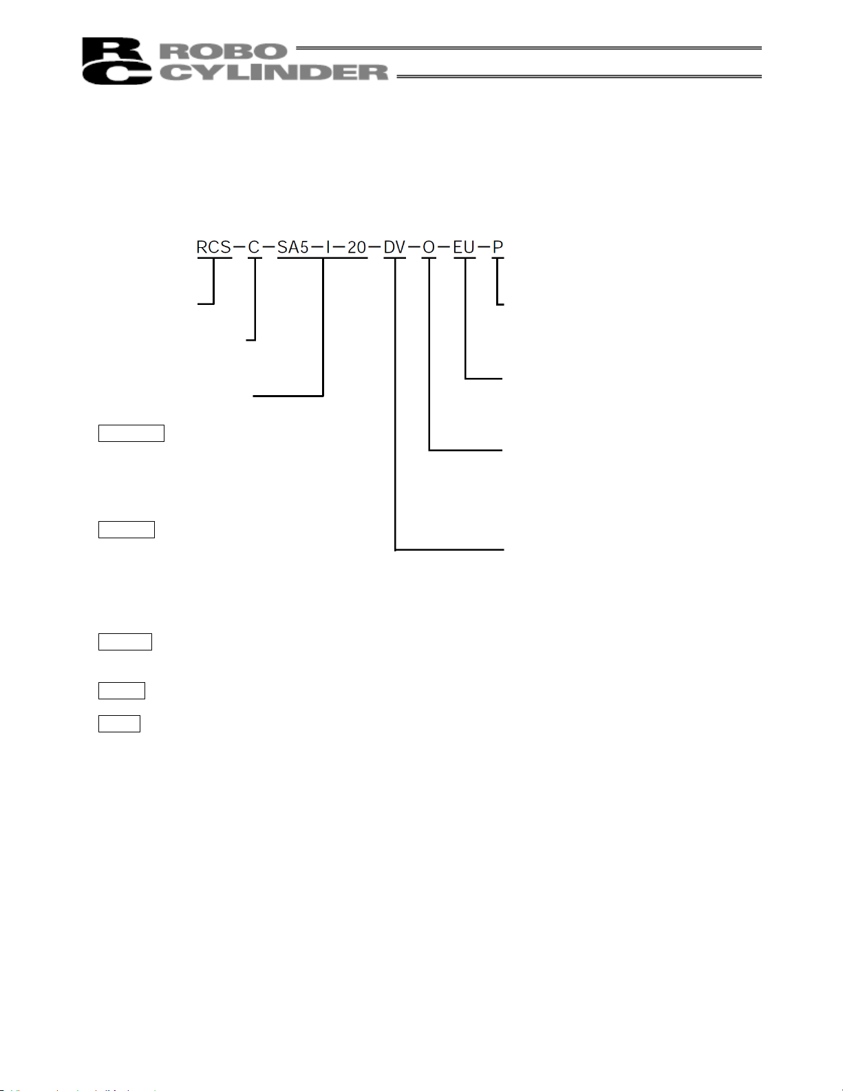
1.2 How to Read Model Number
<Series>
<Controller type>
C: Standard
<Applicable actuator>
[1] Actuator type
Slider type
SA4
SA5
SA6
SS SSR
SM SMR
Rod type
RA35 RA35R
RA45 RA45R
RA55 RA55R
RB7525
RB7530
RB7535
Flat type
F45
F55
Gripper
G20
Rotary
R10
R20
R30
[2] Encoder type
I: Incremental
A: Absolute
[3] Motor capacity
20 (20 W)
30 (30 W)
60 (60 W)
100 (100 W)
150 (150 W)
<I/O signal type>
P: PNP specification [Source]
Blank: NPN specification [Sink]
<CE compliance>
EU: CE-compliant
Blank: Not CE-compliant
<Input supply voltage>
0: 24 VDC
1: 100 VAC
2: 200 VAC
<Open network>
DV: DeviceNet specification
CC: CC-Link specification
PR: ProfiBus specification
Blank: Not network-ready
2
Page 13

1.3 Safety Precautions
Read the following information carefully and provide safety measures with due consideration.
This system product has been developed as a drive component for automated machinery and the like, and is
therefore designed not to generate excessive torque or speed beyond the levels needed to drive automated
equipment. However, the following instructions must be strictly observed to prevent an unexpected accident.
1. Do not handle this product in any manner not specified in this manual. If you have questions regarding any of
the information provided in this manual, please contact IAI.
2. Always use a genuine cable specified by IAI for connecting the actuator and RCS controller.
3. Do not enter the operating range of the machine while the machine is operating or is able to operate (the
controller power is ON). If the machine is used in a place accessible to other people, enclose its operating
range using a safety cage, etc.
4. Always turn off the power supply to the controller before assembling/adjusting or maintaining/inspecting the
machine. During assembly/adjustment or maintenance/inspection, put a plate or other visible sign in a
conspicuous place indicating that work is in progress. The operator should keep the entire power cable
beside him or her to prevent another person from inadvertently plugging in the cable.
5. If two or more persons work together, set signaling methods so each person can confirm the safety of
other(s) during work. Especially when the work requires an axis or axes to be moved—with or without the
power and by motor drive or manual operation—the person moving each axis should always call out
beforehand to ensure safety.
6. If you have extended a cable or made other alteration to the standard wiring specification, thoroughly check
the wiring and ensure absence of problem before turning on the power, in order to prevent malfunction due to
miswiring.
3
Page 14

1.4 Warranty Period and Scope of Warranty
The RCS controller you have purchased passed IAI’s shipping inspection implemented under the strictest
standards. The unit is covered by the following warranty:
1. Warranty Period
The warranty period shall be one of the following periods, whichever ends first:
18 months after shipment from our factory
12 months after delivery to a specified location
2. Scope of Warranty
If an obvious manufacturing defect is found during the above period under an appropriate condition of use,
IAI will repair the defect free of charge. Note, however, that the following items are excluded from the scope
of warranty:
Aging such as natural discoloration of coating
Wear of a consumable part due to use
Noise or other sensory deviation that doesn’t affect the mechanical function
Defect caused by inappropriate handling or use by the user
Defect caused by inappropriate or erroneous maintenance/inspection
Defect caused by use of a part other than IAI’s genuine part
Defect caused by an alteration or other change not approved by IAI or its agent
Defect caused by an act of God, accident, fire, etc.
The warranty covers only the product as it has been delivered and shall not cover any losses arising in
connection with the delivered product. The defective product must be brought to our factory for repair.
Please read carefully the above conditions of warranty.
4
Page 15
1.5 Installation Environment and Noise Elimination
Pay due attention to the installation environment of the controller.
1.5.1 Installation Environment
(1) When installing and wiring the controller, do not block the cooling ventilation holes. (Insufficient ventilation
will not only prevent the controller from demonstrating its full performance, but it may also cause
breakdown.)
(2) Prevent foreign matter from entering the controller through the ventilation holes. Since the enclosure of the
controller is not dustproof or waterproof (oilproof), avoid using the controller in a place subject to significant
dust, oil mist or splashes of cutting fluid.
(3) Do not expose the controller to direct sunlight or radiating heat from a large heat source such as a heat
treatment furnace.
(4) Use the controller in an environment free from corrosive or inflammable gases, under a temperature of 0 to
40C and humidity of 85% or less (non-condensing).
(5) Use the controller in an environment where it will not receive any external vibration or shock.
(6) Prevent electrical noise from entering the controller or its cables.
1.5.2 Power Supply
The power supply specification is 24 VDC, 100 VAC or 200 VAC depending on the controller type.
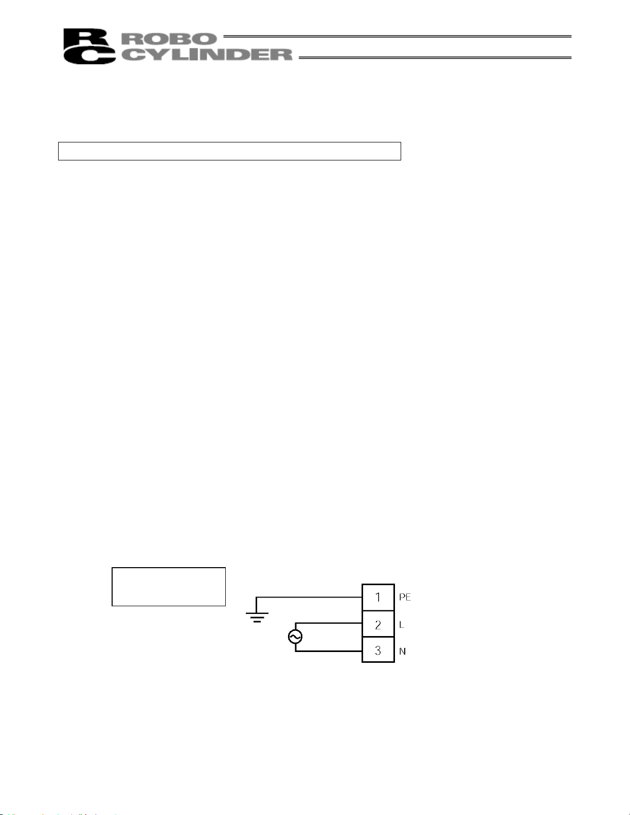
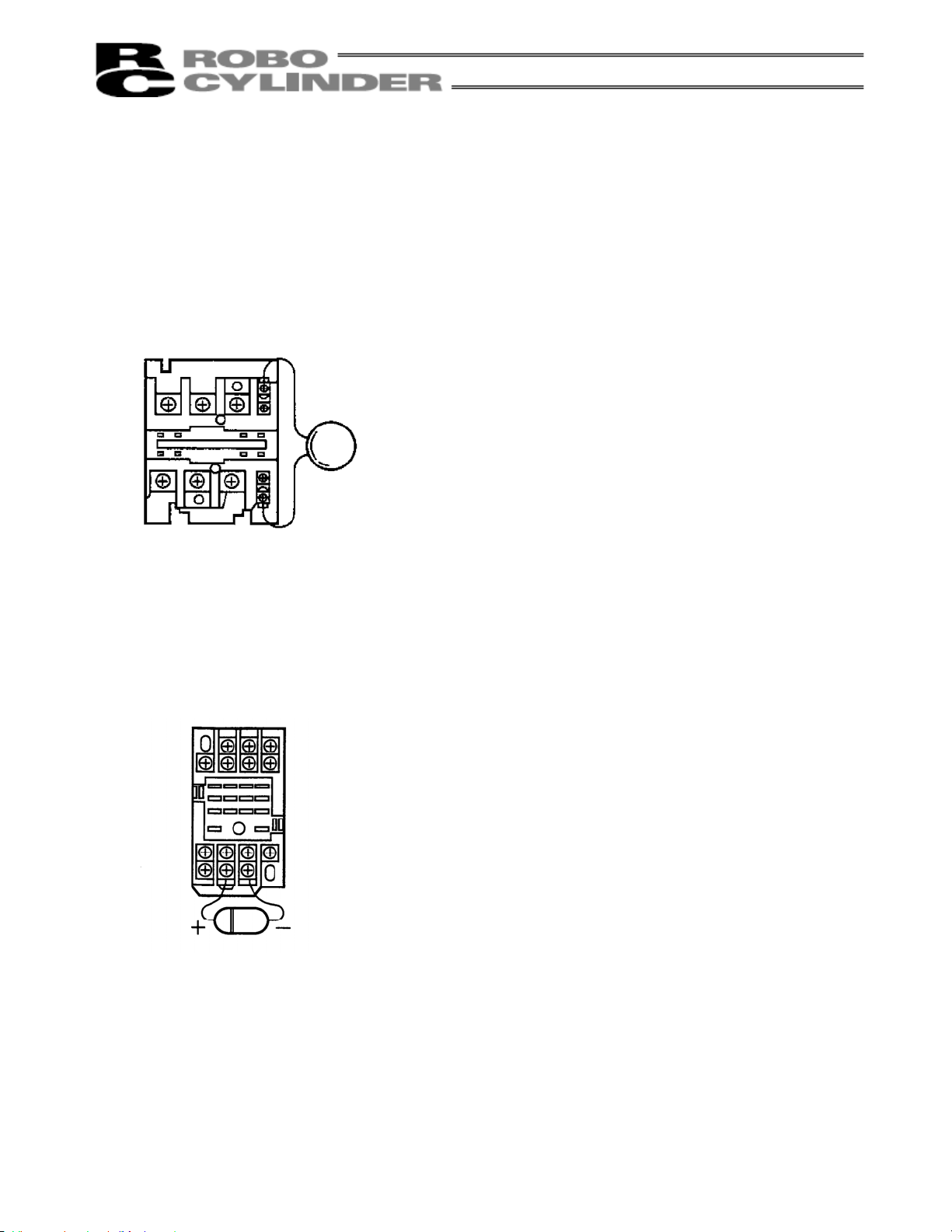
1.5.3 Noise Elimination and Grounding
(1) Wiring and power supply
[1] 100/200-VAC controller
PE on the power terminal block is a protective grounding terminal. Provide Class D grounding.
Use a grounding cable of 0.75 mm
cable.
Class D grounding
(protective grounding)
2
(AWG18) or larger. The grounding cable must be longer than the AC
100/200-VAC power supply
5
Page 16
[2] 24-VDC controller
The power terminal block does not have a protective grounding terminal, but the user must separately
provide a noise elimination measure and grounding.
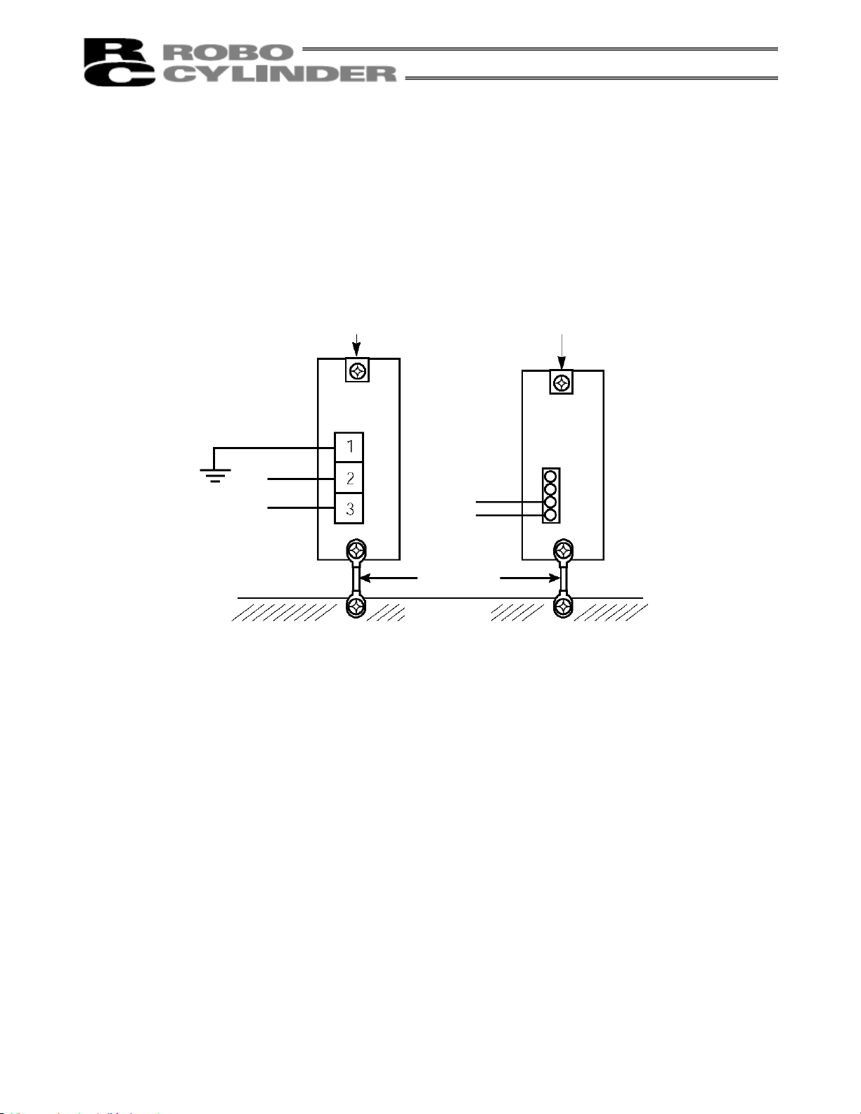
(2) Grounding for noise elimination
Regardless of whether the power supply is 100/200 VAC or 24 VDC, the controller must always be
grounded to eliminate noise.
[1] Connect the controller by directly screwing it onto a metal frame.
Protective grounding
100/200-V
controller
24-V
controller
(AC power supply)
(24 VDC)
Use a cable of
a maximum
possible size
and keep the
wiring distance
at a minimum.
Metal frame
[2] If the controller cannot
be screwed onto the
frame, connect it to the
frame as shown in the
figure at left.
[3] Precautions regarding wiring method
Use a twisted cable for connection to the 24-VDC external power supply.
Separate the controller cables from high-power lines such as a cable connecting to a power circuit. (Do
not bundle together the controller cables with high-power lines or place them in the same cable duct.)
When extending the supplied motor cable or encoder cable, consult IAI’s Technical Support.
6
Page 17
(3) Noise sources and elimination
Among the numerous noise sources, solenoid valves, magnet switches and relays are of particular
concern when building a system. Noise from these sources can be eliminated by implementing the
measures specified below.
[1] AC solenoid valves, magnet switches and relays
Measure: Install a surge absorber in parallel with the coil.
[2] DC solenoid valves, magnet switches and relays
Measure: Install a diode in parallel with the coil. Determine the diode capacity in accordance with the load
capacity.
Point
Install a surge absorber to each coil over a minimum wiring length.
Installing a surge absorber to the terminal block or other part will
be less effective because of a longer distance from the coil.
In a DC circuit, connecting a diode in reverse polarity will damage the
diode, internal parts of the controller and/or DC power supply, so exercise
due caution.
7
Page 18
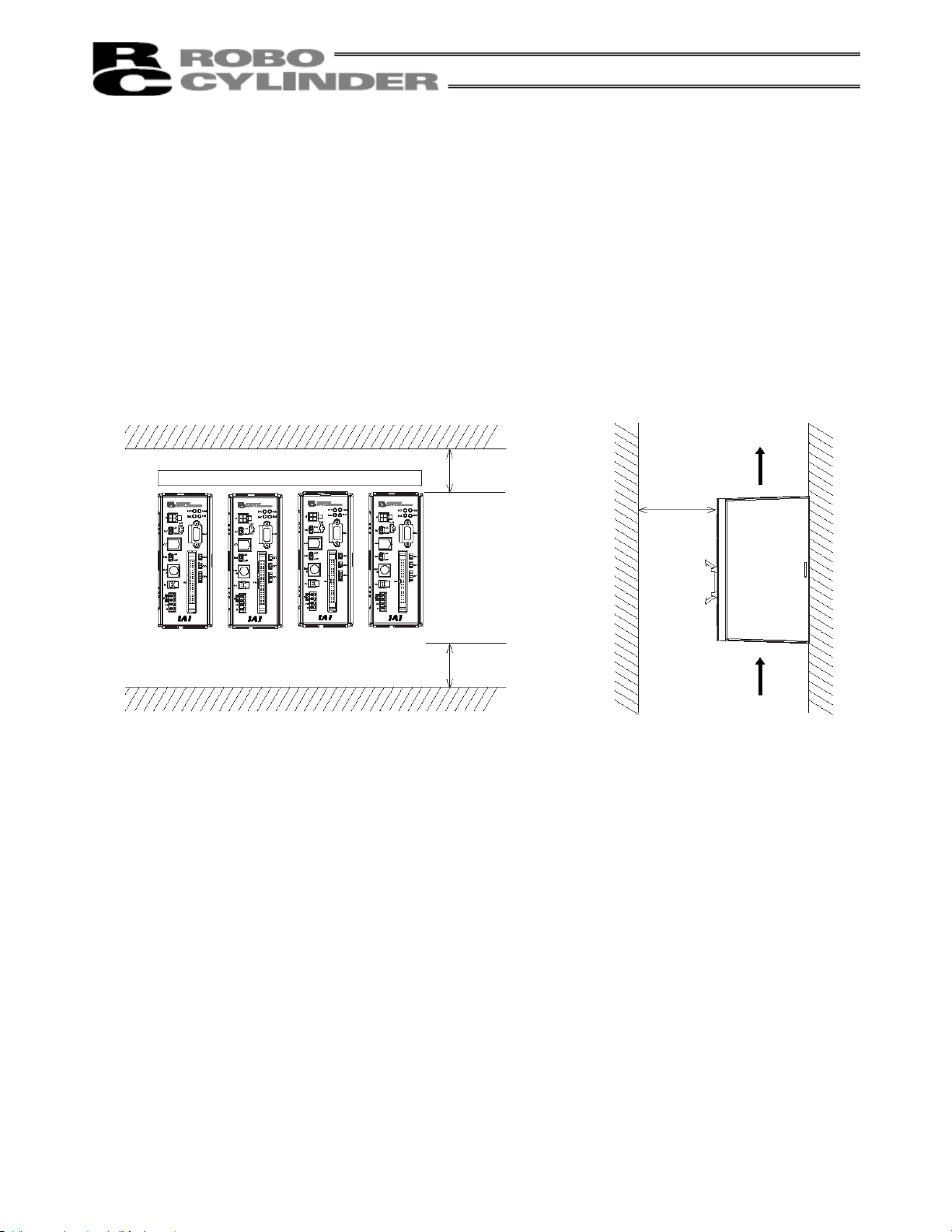
1.6 Heat Radiation and Installation
Design the control panel size, controller layout and cooling method in such a way that the temperature around
the controller will not exceed 40C.
Install the controller vertically on a wall, as shown below. Since cooling is provided by way of natural convection,
always observe this installation direction and provide a minimum clearance of 50 mm above and below the
controller to ensure sufficient natural airflows.
When installing multiple controllers side by side, providing a ventilation fan or fans above the controllers will help
maintain a uniform temperature around the controllers.
Keep the front panel of the controller away from the wall (enclosure) by at least 100 mm.
Regardless of whether your system consists of a single controller or multiple controllers, provide sufficient
clearances around each controller so that it can be installed/removed easily.
Fan
50 mm or more
50 mm or more
100 mm or
more
Airflow
8
Page 19
2. Specification for 24-VDC Input Power
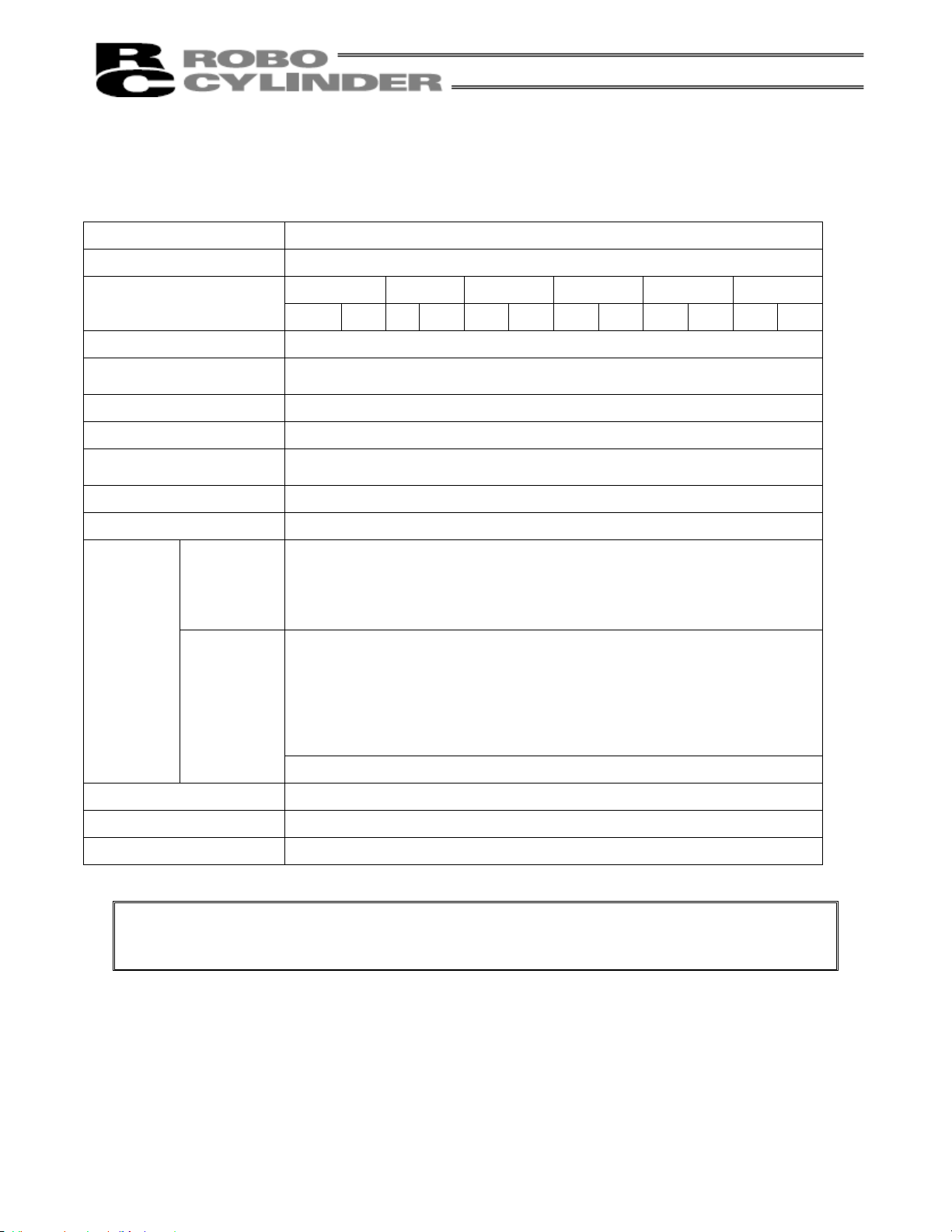
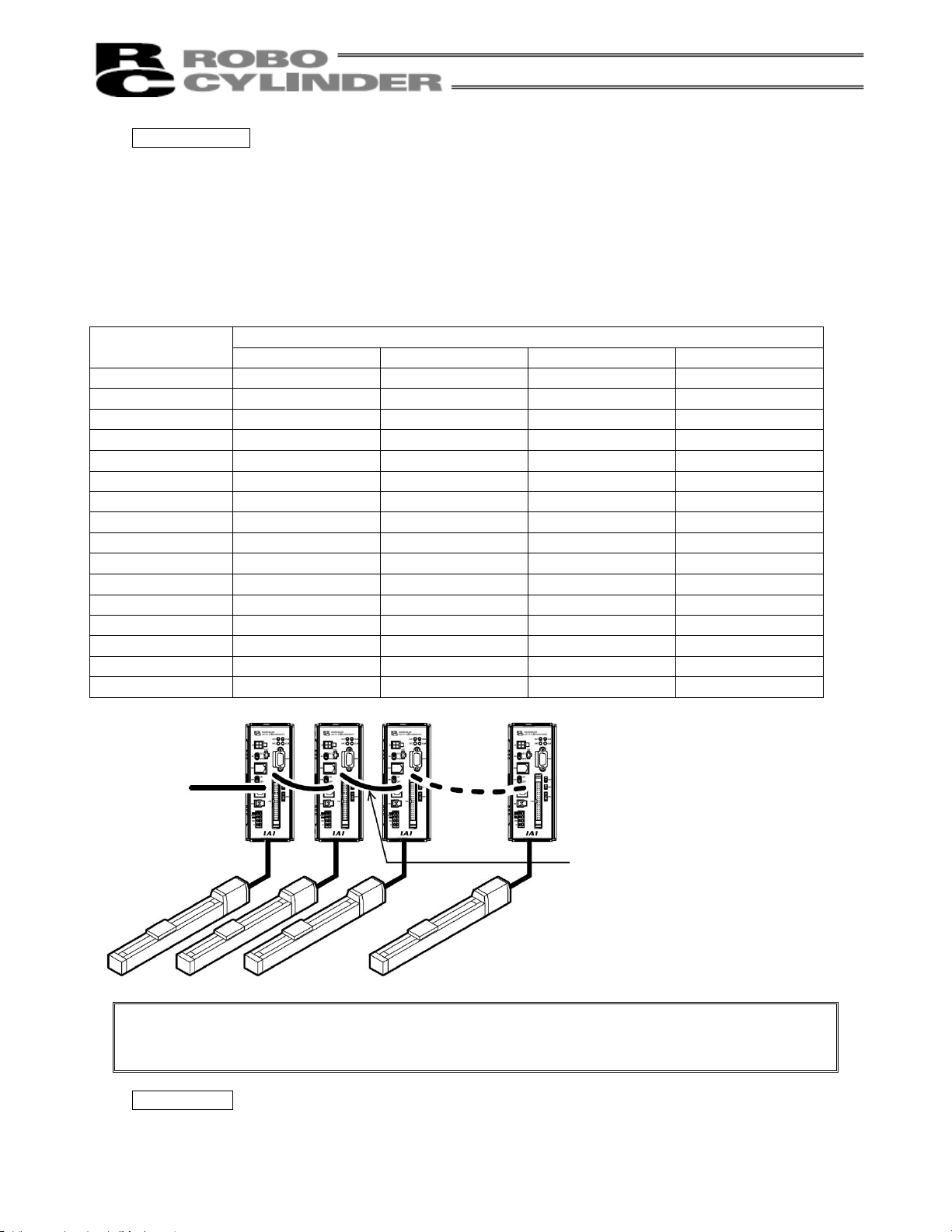
2.1 Basic Specifications
Item Specification
Supply voltage
Type RA35 RA45, F45 RB75 (60 W) SA4, SA5 SA6
24 VDC 10%
Supply current [A]
Rating Peak
1.8 4.3 2.4 6.0 3.9 7.5 1.2 3.7 1.4 3.9
Maximum motor output 60 W (Torque limit x 2) / Other (x 3)
Surrounding air
temperature/humidity
0 to 40C, 85%RH or less
Surrrounding environment IP10, free from corrosive gases
Weight 540 g (Standard), 740 g (Absolute specification)
Protective functions
Regenerative voltage error, motor overcurrent, power-stage overheat,
encoder error, motor overload, overspeed
LED indicators RDY (ready), RUN, ALM (alarm), ENC (encoder error)
DI/DO interface 24 VDC, isolated
Start
8 dedicated
input ports
Command position number (4-bit binary)
* Pause
Reset
Servo ON
Completed position number (4-bit binary)
Input/output
Position complete
Home return completion
10 dedicated
output ports
Zone
* Alarm
* Emergency stop
Moving
Serial interface input/output
Number of positions 16
Data entry method Teaching pendant, PC software
Storage device EEPROM 8 kbytes, S-RAM 128 kbytes
Note: Supplying the power-supply port or any I/O port with a voltage beyond the specified level may
result in controller failure.
* indicate a b-contact signal.
9
Page 20

2.1.1 Backup Battery (Absolute Specification)
(1) Battery Specification
Item Description
Model number AB-1
Type Lithium battery
Manufacturer Toshiba Battery Co., Ltd. (ER6VP)
Nominal voltage 3.6 V
Rated capacity 2000 mAh
Weight Approx. 8.5 g
Battery retention time Note 1)
Note 1) Approx. 100 A of current is consumed while data is backed up by the absolute data backup
battery (as opposed to approx. 4 A consumed while the main controller power is on).
* Do not modify or extend the wires. It may cause failure.
* The battery is replaced together with the board. Since what you will replace is not the battery alone,
always use the product specified by IAI.
* An absolute reset must be performed after the battery has been replaced.
Approx. 20,000 hours (at surrounding air temperature of
20C).
10
Page 21
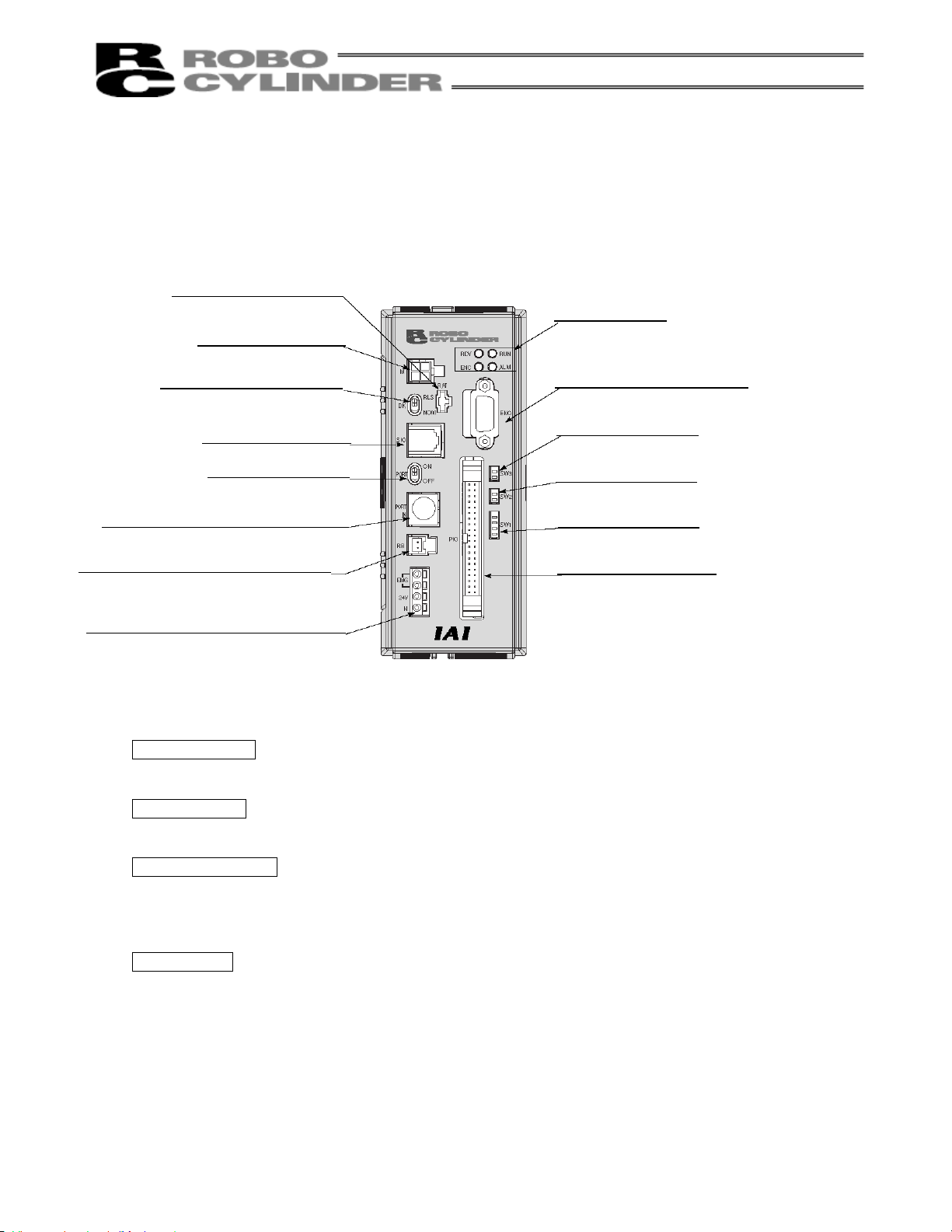
2.2 Names and Functions of Parts
2.2.1 Names
[6] Main communication port connector
(PORT IN)
[7] Regenerative resistor connector (RB)
[8] Power/emergency-stop terminal block
2.2.2 Functions
[1] Battery connector
[2] Motor connector (M)
[3] Brake release switch (BK)
[4] SIO connector (SIO)
[1] Battery connector (BAT)
(absolute specification)
[2] Motor connector (M)
[3] Brake release switch (BK)
[4] SIO connector (SIO)
[5] Port switch (PORT)
A connector for absolute-data backup battery (absolute specification).
A connector for the actuator’s motor power cable.
This switch is available only when the brake option is selected.
RLS: Brake is forcibly released
NOM: Brake is in use (Normal setting)
A connector for linking another controller when two or more controllers are connected.
[9] LED indicators
[10] Encoder/brake connector
(ENC)
[11] Piano switches 3
(SW3)
[12] Piano switches 2
(SW2)
[13] Piano switches 1
(SW1)
[14] PIO connector (PIO)
11
Page 22

[5] Port switch (PORT)
ON: The PORT IN port (teaching pendant/PC software) becomes active. If a dedicated teaching pendant
or cable is not connected to this port, the controller will recognize an emergency-stop condition.
OFF: The PORT IN port (teaching pendant/PC software) becomes inactive. (Controller-to-controller
communication is possible.)
[6] Main communication port connector (PORT IN)
A connector for receiving the communication cable from a dedicated teaching pendant or external
equipment. It also receives a controller link cable when two or more axes are connected.
[7] Regenerative resistor connector (RB)
A connector for regenerative discharge resistor.
The controller will come with a regenerative resistor if the specified actuator capacity is 30 W or above.
However, connection is basically optional, and it should be connected when a regenerative discharge
error occurs. The error code of the regenerative discharge error is “0C9.”
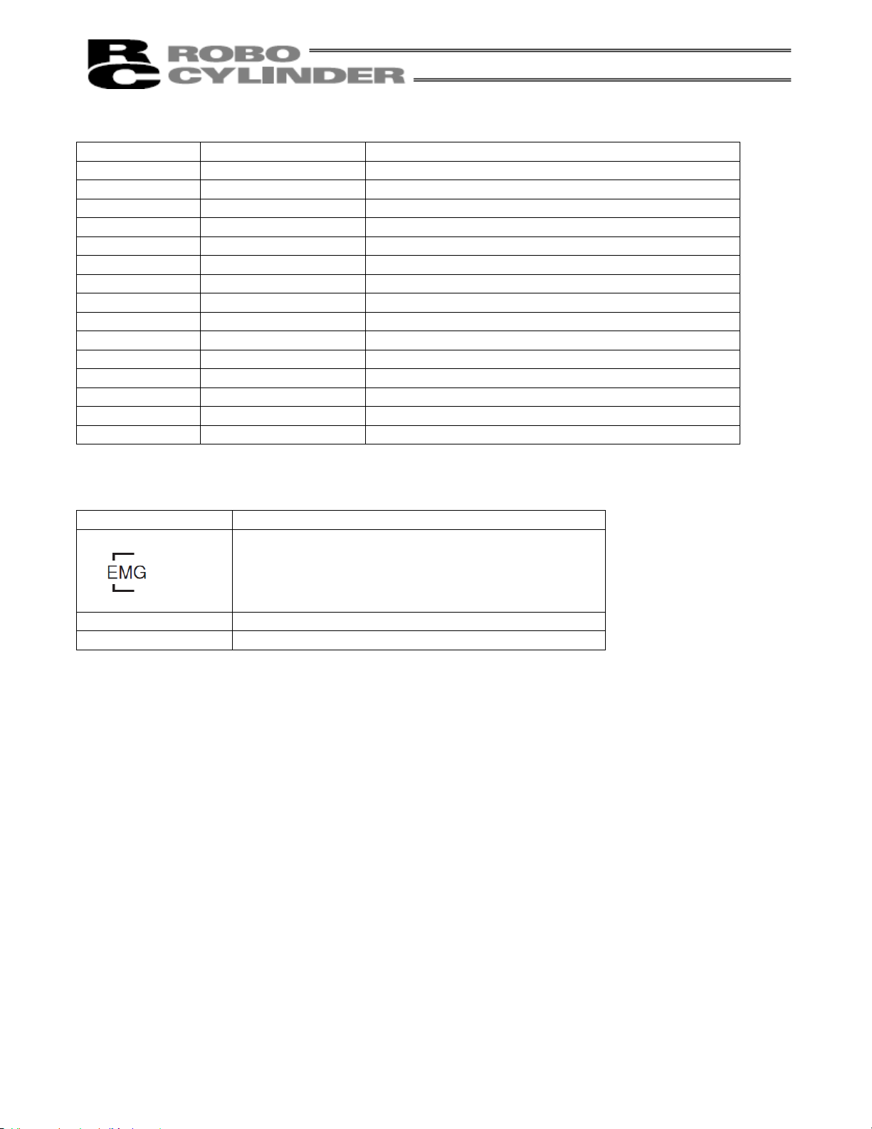
[8] Power/emergency-stop terminal block
EMG: Both terminals are used to connect an emergency-stop switch. (The controller is shipped with the
EMG terminals shorted.)
24V: Connect the positive side of the 24-VDC power supply.
N: Connect the negative side of the 24-VDC power supply.
[9] LEDs
RDY (green): Indicate that the CPU is operating normally.
RUN (green): This LED turns on while the actuator is moving.
ALM (red): This LED remains lit while an alarm is present.
ENC (orange): This LED turns on when the encoder cable is open or otherwise the encoder cannot be
recognized.
[10] Encoder/brake connector (ENC)
A connector for encoder/brake power cable.
[11] Piano switches 3
Switches for selecting the encoder voltage. Use these switches if a custom cable is used and possibility of
voltage drop must be taken into consideration.
Set switches 1 and 2 to ON or OFF in accordance with the cable length.
1 2 Cable length
ON OFF 1 to 5 m
OFF ON 5 to 10 m
ON ON 10 to 15 m
Note: All piano switches are designated as Nos. 1, 2, etc., from the bottom.
With the piano switch in front of you, tilt it to the right side to turn on the switch, or tilt it to the
left side to turn off the switch.
[12] Piano switches 2
1 (bottom): ABS-CLR. Clear the absolute encoder data. Set this switch to ON when performing an
absolute reset. --- Normally OFF
2 (top): FWP. Write protect switch. Set this switch to ON when performing a remote upload.
--- Normally OFF
12
Page 23
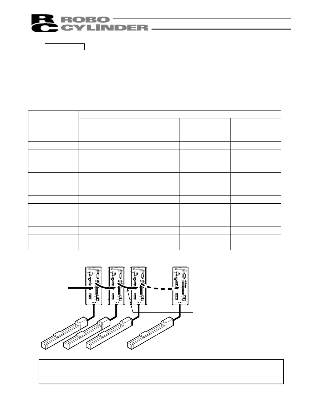
[13] Piano switches 1 (SW1)
Nos. 1 to 4 --- Address switches
Use these switches to set the address of the applicable actuator if two or more axes are connected to the
SIO connector. A desired address between 0 to 15 can be set.
(The factory setting is OFF for all of switch Nos. 1 to 4. This setting represents a condition where only one
axis is used.)
Use these switches to set a desired address for each controller. Make sure no address is duplicated
among the controllers. As long as they are unique, the addresses may not be contiguous and missing
numbers are allowed.
Address
1 2 3 4
Piano switch numbers
0 OFF OFF OFF OFF
1 ON OFF OFF OFF
2 OFF ON OFF OFF
3 ON ON OFF OFF
4 OFF OFF ON OFF
5 ON OFF ON OFF
6 OFF ON ON OFF
7 ON ON ON OFF
8 OFF OFF OFF ON
9 ON OFF OFF ON
10 OFF ON OFF ON
11 ON ON OFF ON
12 OFF OFF ON ON
13 ON OFF ON ON
14 OFF ON ON ON
15 ON ON ON ON
The controller link cable is 200
mm long.
A maximum of 16 controllers can
be connected.
Note: If multiple controllers are connected using link cables, the EMERGENCY STOP/ENABLE SW
on the teaching pendant (optional) becomes effective only with respect to the controller to
which the teaching pendant is connected.
[14] PIO connector (PIO)
A connector for PIO cable.
13
Page 24

2.2.3 Pin Assignments of the Communication Ports
Pin assignments of the SIO connector
Pin No. Signal name Function
1 (+5V) (5-VDC power output) or (preliminary signal terminal)
2 SGA Positive logic side of the line transceiver I/O
3 GND Communication ground
4 SGB Negative logic side of the line transceiver I/O
5 GND Communication ground
6 (+5V) 5-VDC power output
Pin assignments of the main communication port
Pin No. Signal name Function
1 SGA Serial communication
2 SGB Serial communication
3 5V 5-V power output
4 EMGS Emergency-stop status
5 EMGA *1
6 24V 24-V power output
7 GND Ground
*1 Used to actuate an emergency stop (contact b).
Short these pins to cancel an emergency stop.
Motor connector [Molex 5569-04A1]
8 ENGB *1
Pin No. Signal name Connected wire
1 U Motor phase U
2 V Motor phase V
3 W Motor phase W
4 (NC)
14
Page 25
Encoder/brake connector [High-density D-sub, DE-15 type]
Pin No. Signal name Connected wire
1 EN A+ Encoder A+
2 EN A– Encoder A3 EN B+ Encoder B+
4 EN B– Encoder B5 EN Z+ Encoder Z+
6 EN Z– Encoder Z7 SD+ Encoder SD+
8 SD– Encoder SD-
9 BAT+ (Battery+)
10 GND (Battery-)
11 EN 5 Encoder 5V+
12 EN GND Encoder COM13 BK N Brake14 BK P Brake+
15 FG Shield
Power/emergency-stop terminal block [Sato ML-800S IH (4P)]
Signal Name Connected wire
[2]
[1]
These terminals are connected to the emergency stop
circuit.
24 V is output to [1].
(These terminals have been shorted prior to shipment.)
24 V Positive side of the 24-V power supply
N Negative side of the 24-V power supply
24 V and ENG [1] are connected internally.
15
Page 26
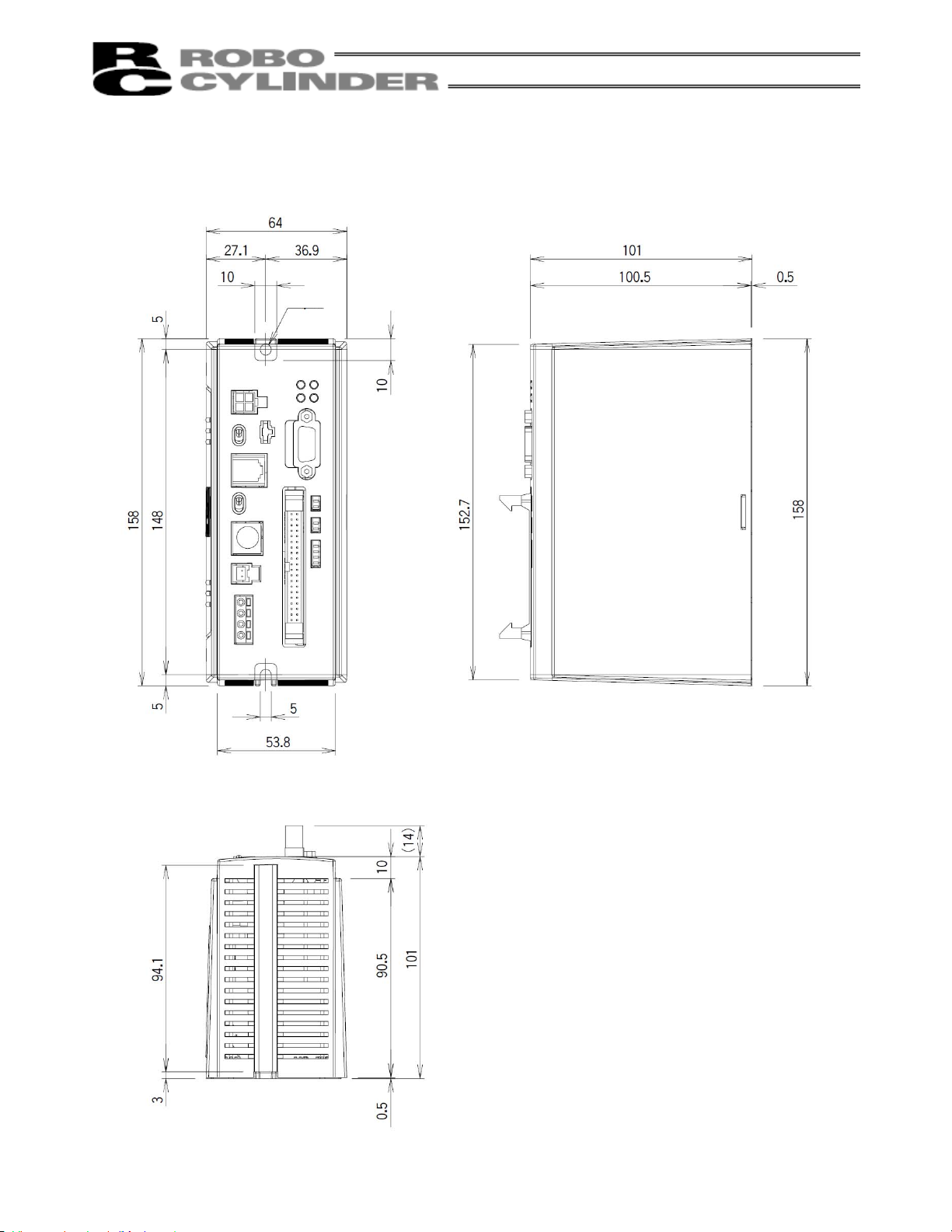
2.3 External Dimensional Diagram
2.3.1 Standard Specifications
5
16
Page 27
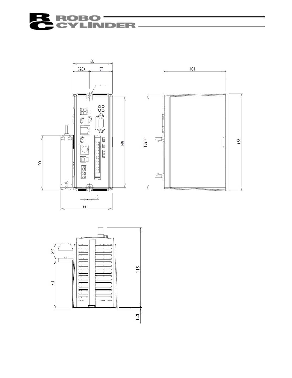
2.3.2 Absolute Specification
5
17
Page 28
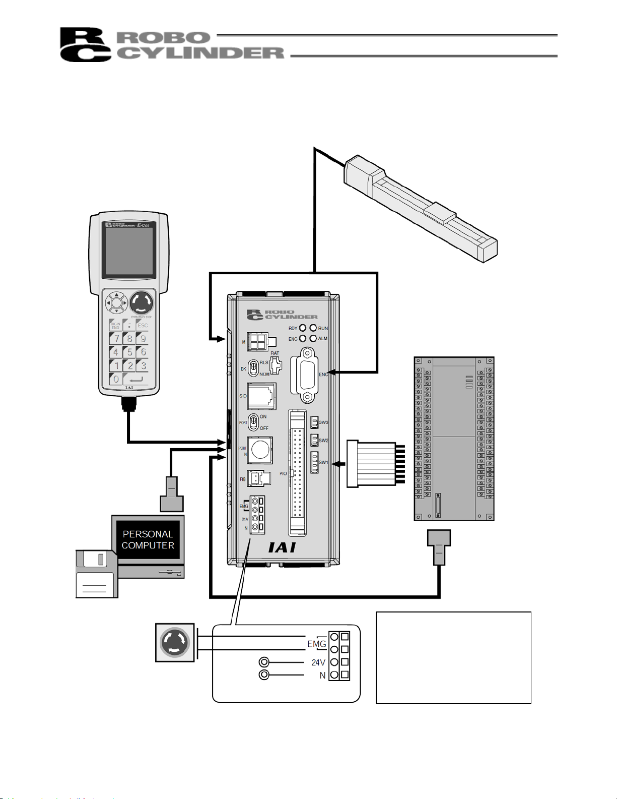
2.4 Connection Method
2.4.1 Standard Type
Teaching pendant
<RCA-T/TD>
Optional
Cable length: 5 m
External unit
<RCA-105-5>
Optional
Cable length: 5 m
PC
PC software
<RCA-101-MW>
Optional
EMG switch
24-VDC
power
supply
ROBO Cylinder <RCS>
The cables are optional.
Host system <PLC>
Supplied flat
cable
Cable length: 2 m
External unit
<RCA-105-5>
Optional
Cable length: 5 m
Do not insert/remove the
connectors when the power is
on, except for the main
communication port connector
(PORT IN). To insert/remove the
PORT IN connector, do so after
turning the PORT switch to OFF.
18
Page 29
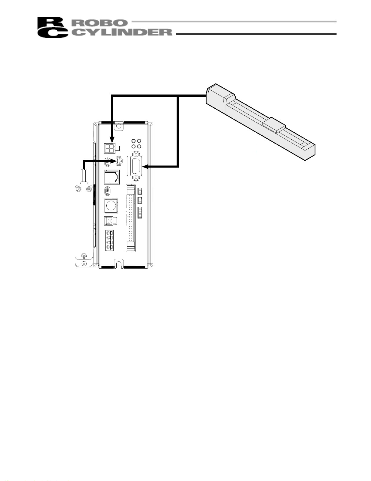
2.4.2 Absolute Specifications
Battery
ROBO Cylinder <RCS>
The absolute specification
cannot be used with a
standard actuator.
The cables are optional.
Other connections are the
same as those of the
standard type.
19
Page 30
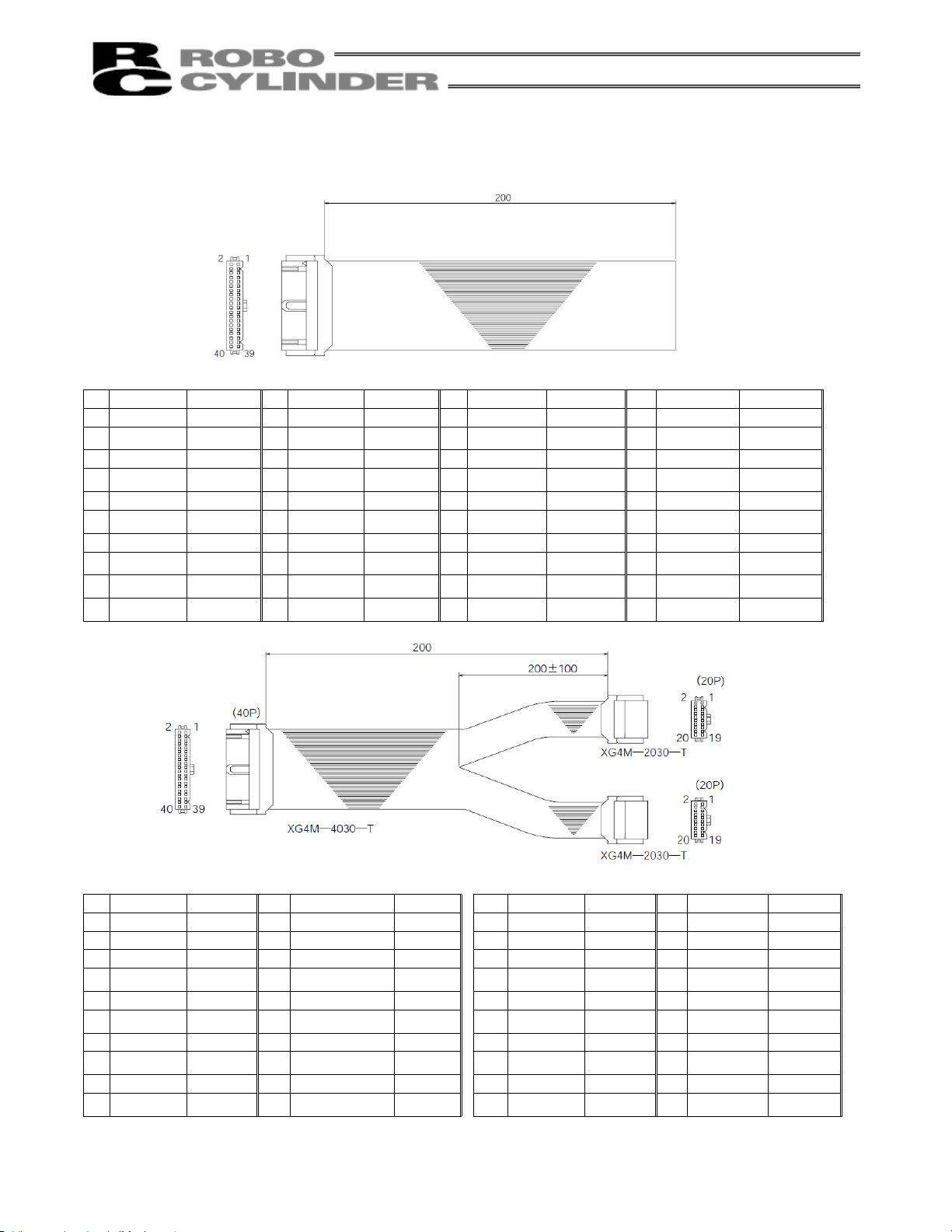
2.5 Supplied Cable
2.5.1 I/O Flat Cable
Accessory
No Signal name Color No Signal name Color No Signal name Color No Signal name Color
1 COM-OA Brown-1 11 NC Brown-2 21 COM-IA Brown-3 31 NC Brown-4
2 COM-OA Red-1 12
3 COM-OB Orange-1 13 NC Orange-2 23 COM-IB Orange-3 33 NC Orange-4
4 COM-OB Yellow-1 14
5 NC Green-1 15 NC Green-2 25 NC Green-3 35 NC Green-4
6 *Alarm Blue-1 16
7 NC Purple-1 17 Moving Purple-2 27 NC Purple-3 37 NC Purple-4
8 Zone Gray-1 18
9 NC White-1 19
Home return
10
completion
• Optional
I/O connector
No Signal name Color No Signal name Color No Signal name Color No Signal name Color
1 COM-OA Brown-1 11 NC Brown-2 1 COM-IA Brown-1 11 NC Brown-2
2 COM-OA Red-1 12 Position complete Red-2 2 COM-IA Red-1 12 Start Red-2
3 COM-OB Orange-1 13 NC Orange-2 3 COM-IB Orange-1 13 NC Orange-2
4 COM-OB Yellow-1 14
5 NC Green-1 15 NC Green-2 5 NC Green-1 15 NC Green-2
6 *Alarm Blue-1 16
7 NC Purple-1 17 Moving Purple-2 7 NC Purple-1 17 NC Purple-2
8 Zone Gray-1 18
9 NC White-1 19 *Emergency stop White-2 9 NC White-1 19 NC White-2
Home return
10
completion
* The I/O connector (40P) is the same as the above accessory
I/O connector (40P)
Completed
position 8
Completed
position 4
Completed
position 2
*Emergency
Black-1 20
Completed
position 1
Position
complete
stop
I/O connector (40P)
Red-2 22 COM-IA Red-3 32 Start Red-4
Yellow-2 24 COM-IB Yellow-3 34
Blue-2 26 *Pause Blue-3 36
Gray-2 28 Servo ON Gray-3 38
White-2 29 NC White-3 39 NC White-4
Black-2 30 Reset Black-3 40
Flat cable
(Split position)
Output
connector
Command
position 8
Command
position 4
Command
position 2
Command
position 1
Flat cable
(Omron)
Input connector
(Omron)
(Omron)
[A] Output connector (20P) [B] Input connector (20P)
Black-1 20
Completed position
8
Completed position
4
Completed position
2
Completed position
1
Yellow-2 4 COM-IB Yellow-1 14
Blue-2 6 *Pause Blue-1 16
Gray-2 8 Servo ON Gray-1 18
Black-2 10 Reset Black-1 20
Command
position 8
Command
position 4
Command
position 2
Command
position 1
Yellow-4
Blue-4
Gray-4
Black-4
[A]
[B]
Yellow-2
Blue-2
Gray-2
Black-2
20
Page 31

2.5.2 Motor Extension Cable
Controller end
Actuator end
Cable color
Red
White
Black
Signal
abbreviation
Pin no.
Receptacle: 5557-04R (Molex)
Female terminal: 5556-TL (Molex)
2.5.3 Encoder Extension Cable
Controller end
Cable color
Purple
lue/red
Orange/white
Green/white
Orange
Yellow
Brown
Plug connector with hood:
Connect the shield to the hood using a cl amp.
Actuator end
Signal
abbreviation
Pink
White
Blue
Black
Green
Gray
Red
17HE-23150-C (D13A) (DDK)
Contact:
17H-7PCR-102 (P500) (DDK)
Pin no.
Pin no.
Plug housing: SLP-03V (JST)
Socket contact BSF-21T-P1.4 (JST)
Ground and braided shield wires
Signal
abbreviation
Pin no.
Plug housing:
Socket contact:
Retainer:
Cable color
Red
White
Black
Signal
abbreviation
Cable color
Pink
Purple
White
lue/red
Orange/white
Green/white
Ground
Blue
Orange
Black
Yellow
Green
Brown
Gray
Red
XMP-18V (JST)
BXA-001T-PO.6 (JST)
XMS-09V (JST)
21
Page 32

2.6 Wiring
2.6.1 Wiring for Power Supply/Emergency Stop
* The two EMG terminals are contact-b inputs used for connecting an emergency-stop switch. The controller is
shipped with these terminals shorted, so that an emergency stop will not be actuated. 24 VDC is output to
EMG of pin No. 3.
The current consumption of the emergency-stop circuit is approx. 35 mA (24-V controller).
Power/emergency-stop terminal block
Note: When performing power connection, make sure the following specifications for power cable, etc.,
are satisfied.
Applicable cable
Allowable wire size
Single wire --- 1.0 (AWG18)
Stranded wire --- 0.75 mm
Single wire --- 0.4 (AWG26) to 1.2 (AWG16)
Stranded wire --- 0.3 mm
2
(AWG18)
2
(AWG22) to 1.25 mm2 (AWG16)
Element wire diameter --- 0.18 or larger
Standard stripped-wire length 11 mm
Button operation tool
Flathead screwdriver (shaft diameter 3, blade tip width 2.6)
Note: This controller has no power switch.
22
Page 33

r
r
r
2.6.2 External Connection Diagram
PC
Teaching pendant
Conversion
adapter
Moto
connecto
Encoder/brake
connecto
Main
communication port
Brake
Host
system
(PLC)
Conversion adapter
Output
Input
RS485
communication
Start
Command position 1
Command position 2
Command position 4
Command position 8
Pause
Reset
Servo ON
Completed position 1
Completed position 2
Completed position 4
Completed position 8
Position complete
Home return completion
Zone
Alarm
Moving
Emergency stop
To the next controller
External EMG button
Input voltage
23
Page 34

2.6.3 PIO Interface
A PIO interface list is given below.
The PIO cable is a flat cable with no connector attached on the end connected to the external equipment.
PIO connector (40 pins)
Pin
Category
No.
1 [1] COMOA Brown-1 2 [1] COMOA Red-1
3 [2] COMOB Orange-1 4 [2] COMOB Yellow-1
5 Green-1 6 [3] *Alarm Blue-1
7 Purple-1 8 [4] Zone Gray-1
9 White-1 10 [5]
11 Brown-2 12 [6]
Output
13 Orange-2 14
15
17 [8] Moving Purple-2 18
19
21 [10] COMIA Brown-3 22 [10] COMIA Red-3
23 [11] COMIB Orange-3 24 [11] COMIB Yellow-3
25 Green-3 26 [12] *Pause Blue-3
27 Purple-3 28 [13] Servo ON Gray-3
29 White-3 30 [14] Reset Black-3
31 Brown-4 32 [15] Start Red-4
Input NC
33 Orange-4 34
35 Green-4 36
37 Purple-4 38
39
Reference
No.
[9]
Signal name Cable color
NC
*Emergency
stop
Pin
Category
No.
Output
Green-2 16
White-2 20
White-4 40
Input
Reference
No.
[7]
[16]
Signal name Cable color
Home return
completion
Position
complete
Completed
position 8
Completed
position 4
Completed
position 2
Completed
position 1
Command
position 8
Command
position 4
Command
position 2
Command
position 1
Black-1
Red-2
Yellow-2
Blue-2
Gray-2
Black-2
Yellow-4
Blue-4
Gray-4
Black-4
Note: The ports indicated by an asterisk (*) conform to the contact-b signal logic (always ON).
Never connect those ports that are not used.
24
Page 35

[1] COMOA
Power supply for output ports
[2] COMOB
Connect the 24-VDC power supply for output ports between COMOA and COMOB.
COMOA and COMOB have no polarities.
Pin Nos. 1 & 2, and 3 & 4 are connected internally.
[3] Alarm
This signal will turn OFF when an alarm occurs. It remains ON as long as the controller is operating
properly.
To reset an alarm, remove the cause of the alarm, and then input a reset signal or reconnect the power.
[4] Zone
A zone signal will be output when the actuator enters the range set by the applicable parameter.
[5] Home return completion
This signal will turn ON when the initial home return is completed after a power connection. Thereafter, this
signal will remain ON until the power is turned off. It will not turn OFF following an emergency-stop signal
input.
If the home return completion signal is OFF, it means home return will be performed before the next
movement operation.
Note: With the absolute specification, the home return completion signal will turn ON when the power
is turned on, after an absolute reset was executed once. If the home return completion signal
turns OFF due to an alarm, an absolute reset must be executed again.
[6] Position complete
This signal will turn ON when the controller becomes ready following a power connection. It will turn OFF
when a start signal is input, and turn ON when a movement is completed.
[7] Completed position
All completed position signals will turn OFF the moment the position complete signal turns OFF.
All completed position signals remain OFF while an emergency stop is actuated or during the direct
teaching mode.
When the controller returns to the ready mode thereafter, the completed position signal corresponding to
the current actuator position will be output if the current actuator position is within the positioning band from
the last position complete position. If the current actuator position is outside the positioning band, all
completed position signals will remain OFF.
In the push & hold mode, all completed position signals will remain OFF when the controller returns to the
ready mode from an emergency-stop status or the direct teaching mode, regardless of the current actuator
position.
When an alarm occurs, a corresponding alarm code (short form) is output by the four bits of completed
positions 1, 2, 4 and 8. The meanings of these signals vary in a normal state and when an alarm is present,
so exercise caution when writing a sequence program. (Refer to 7.3, "Alarm Output by PIO.")
[8] Moving
This signal remains ON while the actuator is moving.
Use this signal if you want to detect stopping of the motor during pause.
25
Page 36

[9] Emergency stop
This signal will turn OFF when an emergency stop is actuated. It remains ON as long as the controller is
operating properly.
When the emergency stop is cancelled, the signal will turn ON.
[10] COMIA
Power supply for input ports
[11] COMIB
Connect the 24-VDC power supply for input ports between COMIA and COMIB.
Pin Nos. 21 & 22, and 23 & 24 are connected internally.
[12] Pause
This is a contact-b input. Keep the signal ON while the actuator is moving, and cause it to turn OFF when
the movement pauses.
[13] Servo ON
The servo is ON while this signal is ON.
[14] Reset
An alarm will be reset once a rise of this signal is detected. If the cause of the alarm is not yet removed, the
alarm will come back after the reset action.
When this signal is input while the actuator is in pause, the remaining travel will be cancelled.
[15] Start
Inputting this signal will start movement.
[16] Command position
Input the position number you want to select.
Relationship of input pin numbers and selected position numbers (4-bit binary)
One of 16 positions from 0 to 15 can be input/selected.
1: ON 0: OFF
Pin No.
Command position 1
40
Command position 2
38
Command position 4
36
Command position 8
34
0 1 0101010101 0 1 01
0 0 1100110011 0 0 11
0 0 0011110000 1 1 11
0 0 0000001111 1 1 11
Selected position No. 0 1 234567891011 12 13 1415
Note: The actuator will not operate if the start input is turned ON after selecting a position number for
which no position data is entered. (A bank 31 error (alarm code: 0B1) will occur.)
26
Page 37

2.6.4 External I/O Specifications
Input Part
Item Specification
Number of input points 8 points
Input voltage
24 VDC 20
Input current 7 mA per circuit
Operating voltage
ON voltage --- 16 V min. (4.5 mA)
OFF voltage --- 6 V max. (1.4 mA)
Isolation method Photocoupler
Internal circuit configuration (Standard NPN specification)
Pin No.
External
power supply
24 VDC
Rectifier
Each input
Connect a 24-V power supply between COMIA and COMIB.
Connect the input common to the negative side of the external power supply.
Pin Nos. 21 and 22 of COMIA and 23 and 24 of COMIB are connected internally.
Internal circuit configuration (Optional PNP specification)
Each input
Pin No.
External
power supply
24 VDC
Rectifier
Internal circuit
Internal circuit
Connect a 24-V power supply between COMIA and COMIB.
Connect the input common to the positive side of the external power supply.
Pin Nos. 21 and 22 of COMIA and 23 and 24 of COMIB are connected internally.
27
Page 38

p
Output Part
100-mA output circuit by power MOSFET
Item Specification
Number of output points 10 points
Rated load voltage 24 VDC; 60 VDC (peak) (without flywheel diode)
Maximum load current 100 mA per point
Residual voltage 1.8 V / 100 mA
Isolation method Photocoupler
Overcurrent protection
Fuse resistance: 10 , 0.1 W
Internal circuit configuration (Standard NPN specification)
Each out
Fuse resistance:
Internal circuit
Rectifier
ut
Load
Load
Pin No.
External
power supply
24 VDC
Supply 24 VDC between COMOA and COMOB. COMOA and COMOB have no polarities.
Pin Nos. 1 & 2, and 3 & 4, are connected internally.
Note 1) The output circuit is an open-drain circuit provided by a power MOSFET and has no flywheel diode.
When connecting a load, such as a relay, also connect a diode, etc., to suppress flyback voltage.
(Spike noise can be eliminated most effectively when a diode is connected at the closet possible
position to the coil).
Internal circuit configuration (Optional PNP specification)
Pin No.
External
Rectifier
Load
Fuse resistance:
Each output
Load
Internal circuit
power supply
24 VDC
28
Page 39

3. Input Power 100/200 VAC Specification
3.1 Base Specification
Item Specification
Supply voltage 90 to 125 / 180 to 250 VAC
RA55 (60 W),
SSR (60 W),
F55 (60 W)
Supply current [VA]
Type
Rating Peak 152 487 246 700 333 1026 166 546 265 902 364 1285
RB75
(60 W)
RB75
(100 W)
RB75
(150 W)
Maximum motor output 150 W (torque limit at 3 times)
Rush current (maximum
instantaneous value)
Surrounding air
temperature/humidity
44 A
(Select the medium-speed type for the NFB.)
0 to 40C, 85%RH or less
Surrounding environment IP10, free from corrosive gases
Weight Standard: 1,320 g / Absolute specification: 1,610 g
Protective functions
Regenerative voltage error, motor overcurrent, power-stage overheat,
encoder error, motor overload, overspeed
Withstand voltage (Note 2) 1500 VAC, 1 minute
RA55 (100 W),
SMR (100 W),
F55 (100 W)
SMR
(150 W)
LED indicators RDY (green), RUN (green), ALM (red), ENC (orange)
DI/DO interface 24 VDC, isolated
Start
8 dedicated
input ports
Command position number (4-bit binary)
Pause
Reset
Servo ON
Completed position number (4-bit binary)
Input/output
(Note 1)
Position complete
Home return completion
Zone
11 dedicated
output ports
Alarm
Emergency stop
Moving
Battery alarm
Serial interface input/output
Number of positions 16
Data entry method Teaching pendant, PC software
Storage device EEPROM 8 kbytes, S-RAM 128 kbytes
(Note 1): Supplying the power-supply port or any I/O port with a voltage beyond the specified level may result
in controller failure.
(Note 2): The withstand voltage of the motor driving the actuator is 1000 V for 1 minute. When conducting a
withstand voltage test while the controller and actuator are connected, make sure a voltage
exceeding 1000 V is not supplied for more than 1 minute.
29
Page 40

3.1.1 Backup Battery (Absolute Specification)
(1) Battery specifications
Item Description
Model number AB-1
Classification Lithium battery
Manufacturer Toshiba Battery (ER6VP)
Nominal voltage 3.6 V
Rated capacity 2000 mAh
Weight Approx. 8.5 g
Battery retention time Note 1)
Note 1) The absolute-data backup battery consumers approx. 100 A during backup. (When the main controller
power is on, the current consumption is approx. 4 A.)
* Do not modify or extend the cable. It may result in controller failure.
* The battery is replaced together with the battery board. The battery cannot be replaced alone. Be sure to use
the battery module specified by IAI.
(2) Battery alarm and battery error
A battery alarm (alarm code: 07A) will occur when the battery voltage drops to approx. 3.1 V. This alarm is
output to PIO connector pin No. 15. The controller operation will not be disabled right away after a battery
alarm occurs. The alarm merely indicates that the battery should be replaced soon. Once a battery alarm
occurs, the controller will generate a battery error in approx. 220 hours (around nine days).
A battery alarm can be temporarily reset by inputting a reset signal or pressing the BEGIN/END key on
the teaching pendant for at least 2.5 seconds.
Note) The battery-alarm function is supported by the 100/200-V controller of version M5 or later.
A battery error will occur when the battery voltage drops to approx. 2.5 V. Once the battery voltage drops
to this level, the controller will detect an error (alarm code: 0E5) the next time the power is turned on. A
battery error is detected only when the controller power is turned on.
The controller operation will be disabled once a battery error occurs. You must replace the battery, and
then execute an absolute reset.
Approx. 20,000 hours (at surrounding air temperature of 20C)
30
Page 41

If the battery was replaced while the controller power was off, the position information (absolute data) may or
may not be retained depending on how long the controller remained without battery.
Time without battery Retention of position information (absolute data)
Less than 5 minutes Position information (absolute data) is retained. Absolute reset is not necessary.
5 to 15 minutes
More than 15 minutes
A battery alarm occurs. Position information is retained. Absolute reset is not
necessary.
A battery error occurs. Position information is not retained. Absolute reset is
necessary.
Note) The position-information (absolute-data) retention function during battery replacement is supported by
the 100/200-V controller of version M5 or later.
If a battery error was already present before the replacement, an absolute reset will be required even if
the controller has been without battery for no more than 15 minutes.
31
Page 42

3.2 Names and Functions of Parts
3.2.1 Names
3.2.2 Functions
[1] Battery connector
A connector for absolute-data backup battery (absolute specification).
[2] Port switch (PORT)
ON: The PORT IN port (teaching pendant/PC software) becomes active. If a dedicated teaching pendant
OFF: The PORT IN port (teaching pendant/PC software) becomes inactive. (The SIO line remains live, so
[3] Brake release switch (BK)
This switch is available only when the brake option is selected.
RLS: Brake is forcibly released
NOM: Brake is in use (Normal setting)
[4] Emergency-stop terminal block
EMG: Both terminals are used to connect an emergency-stop switch.
[1] Battery connector
(absolute specification)
[2] Port switch
[3] Brake release switch
[4] Emergency-stop
terminal block
[5] Motor connector
[6] Power terminal block
[7] LED indicators
[8] Encoder/brake connector
[9] Piano switches 3
[10] Piano switches 2
[11] Piano switches 1
[12] PIO connector
[13] Main communication
port connector
[14] SIO connector
or cable is not connected to this port, the controller will recognize an emergency-stop condition.
controller-to-controller communication is possible.)
32
Page 43

[5] Motor connector
A connector for the actuator’s motor power cable.
[6] Power terminal block
L/N: An AC-power connection terminal.
PE: A protective grounding terminal. Provide class D grounding.
[7] LEDs
RDY: Indicate that the CPU is operating normally.
RUN: This LED turns on while the actuator is moving.
ENC: This LED turns on when the encoder cable is open or otherwise the encoder cannot be recognized.
The LED also turns on when the voltage of the absolute-data backup battery drops.
ALM: This LED remains lit while an alarm is present.
[8] Encoder/brake connector (ENC)
A connector for encoder/brake power cable.
[9] Piano switches 3
Switches for selecting the encoder voltage. Use these switches if a custom cable is used and possibility of
voltage drop must be taken into consideration.
Set switches 1 and 2 to ON or OFF in accordance with the cable length.
1 2 Cable length
ON OFF 1 to 5 m
OFF ON 5 to 10 m
ON ON 10 to 15 m
Note: All piano switches are designated as Nos. 1, 2, etc., from the bottom.
With the piano switch in front of you, tilt it to the right side to turn on the switch, or tilt it to the
left side to turn off the switch.
[10] Piano switches 2
1 (bottom): ABS-CLR. Clear the absolute encoder data. Set this switch to ON when performing an
absolute reset. --- Normally OFF
2 (top): FWP. Write protect switch. Set this switch to ON when performing a remote upload. ---
Normally OFF
33
Page 44
[11] Piano switches 1 (SW1)
Nos. 1 to 4 --- Address switches
Use these switches to set the address of the applicable actuator if two or more axes are connected to the
SIO connector. A desired address between 0 to 15 can be set.
(The factory setting is OFF for all of switch Nos. 1 to 4. This setting represents a condition where only one
axis is used.)
Use these switches to set a desired address for each controller. Make sure no address is duplicated
among the controllers. As long as they are unique, the addresses may not be contiguous and missing
numbers are allowed.
Address
1 2 3 4
Piano switch numbers
0 OFF OFF OFF OFF
1 ON OFF OFF OFF
2 OFF ON OFF OFF
3 ON ON OFF OFF
4 OFF OFF ON OFF
5 ON OFF ON OFF
6 OFF ON ON OFF
7 ON ON ON OFF
8 OFF OFF OFF ON
9 ON OFF OFF ON
10 OFF ON OFF ON
11 ON ON OFF ON
12 OFF OFF ON ON
13 ON OFF ON ON
14 OFF ON ON ON
15 ON ON ON ON
The controller link cable is 200 mm
long.
A maximum of 16 controllers can be
connected.
Note: If multiple controllers are connected using link cables, the EMERGENCY STOP/ENABLE SW
on the teaching pendant (optional) becomes effective only with respect to the controller to
which the teaching pendant is connected.
34
Page 45

[12] PIO connector (PIO)
A connector for PIO cable.
[13] Main communication port connector (PORT IN)
A connector for receiving the communication cable from a dedicated teaching pendant or external
equipment. It also receives a controller link cable when two or more axes are connected.
[14] SIO connector (SIO)
A connector for linking another controller when two or more controllers are connected.
35
Page 46

3.2.3 Signal Tables of Connectors and Terminal Blocks
Pin assignments of the SIO connector
Pin No. Signal name Function
1 (+5V) (5-VDC power output) or (preliminary signal terminal)
2 SGA Positive logic side of the line transceiver I/O
3 GND Communication ground
4 SGB Negative logic side of the line transceiver I/O
5 GND Communication ground
6 (+5V) 5-VDC power output
Pin assignments of the main communication port
Pin No. Signal name Function
1 SGA Serial communication
2 SGB Serial communication
3 5V 5-V power output
4 EMGS Emergency-stop status
5 EMGA *1
6 24V 24-V power output
7 GND Ground
8 ENGB *1
*1 Used to actuate an emergency stop (contact b).
Short these pins to cancel an emergency stop.
Motor connector [Molex 5569-04A1]
Signal name Connected wire
PE Motor FG
U Motor phase U
V Motor phase V
W Motor phase W
36
Page 47

Encoder/brake connector [High-density D-sub, DE-15 type]
Pin No. Signal name Connected wire
1 EN A+ Encoder A+
2 EN A– Encoder A-
3 EN B+ Encoder B+
4 EN B– Encoder B-
5 EN Z+ Encoder Z+
6 EN Z– Encoder Z-
7 SD+ Encoder SD+
8 SD– Encoder SD-
9 BAT+ (Battery+)
10 GND (Battery-)
11 EN 5N Encoder 5V+
12 EN GND Encoder COM-
13 BK N Brake -
14 BK P Brake +
15 FG Shield
Power terminal block [Phoenix]
Signal name Connected wire
PE Ground
L
N
AC single-phase power supply, live side
AC single-phase power supply, ground side
Emergency-stop terminal block
Signal name Connected wire
Connection of emergency stop circuit
(shorted when shipped)
37
Page 48

3.3 External Dimensions
3.3.1 Standard Type
5
38
Page 49

3.3.2 Absolute Specification
39
Page 50

3.4 Connection Method
3.4.1 Standard Type
EMG switch
AC
power
supply
Class D grounding
(protective grounding)
PC
PC software
<RCA-101-MW>
Optional
ROBO Cylinder <RCS>
The cables are optional.
Supplied flat
cable
Cable length: 2 m
External unit
<RCA-105-5>
Optional
Cable length: 5 m
External unit
<RCA-105-5>
Optional
Cable length: 5 m
Teaching pendant
<RCA-T/TD>
Optional
Cable length: 5 m
40
Page 51

3.4.2 Absolute Specifications
Battery
holder
Battery
connector
ROBO Cylinder <RCS>
The absolute specification
cannot be used with a
standard actuator.
The cables are optional.
Other connections are the
same as those of the
standard type.
41
Page 52

3.5 Supplied Cables
3.5.1 I/O Flat Cable Accessory
No. Signal Name Color No. Signal Name Color No. Signal Name Color No. Signal Name Color
1 C OMOA Brown - 1 11 * Emergency stop Brown - 2 21 C OMIA Brown - 3 31 N C Brown - 4
2 C OMOA Red - 1 12
3 C OMOB Orange - 1 13 * Alarm Orange - 2 23 C OMIB Orange - 3 33 * Hold Orange - 4
4 C OMOB Yellow - 1 14 Complete position 8 Yellow - 2 24 C OMIB Yellow - 3 34
5 N C Green - 1 15 Z one Green - 2 25 N C Green - 3 35 Servo ON Green - 4
6 N C Blue - 1 16 Complete position 4 Blue - 2 26 N C Blue - 3 36
7 *Battery alarm Purple - 1 17 Homing complete Purple - 2 27 N C Purple - 3 37 Reset Purple - 4
8 N C Gray - 1 18 Complete position 2 Gray - 2 28 N C Gray - 3 38
9 Moving White - 1 19
10
Optional
No. Signal Name Color No. Signal Name Color No. Signal Name Color No. Signal Name Color
1 C OMOA Brown - 1 11 * Emergency stop Brown - 2 1 C OMIA Brown - 1 11 N C Brown - 2
2 C OMOA Red - 1 12
3 C OMOB Orange - 1 13 * Alarm Orange - 2 3 C OMIB Orange - 1 13 * Hold Orange - 2
4 C OMOB Yellow - 1 14 Complete position 8 Yellow - 2 4 C OMIB Yellow - 1 14
5 N C Green - 1 15 Zone Green - 2 5 N C Green - 1 15 Servo ON Green - 2
6 N C Blue - 1 16 Complete position 4 Blue - 2 6 N C Blue - 1 16
7 *Battery alarm Purple - 1 17 Homing complete Purple - 2 7 N C Purple - 1 17 Reset Purple - 2
8 N C Gray - 1 18 Complete position 2 Gray - 2 8 N C Gray - 1 18
9 Moving White - 1 19
10
* I/O connector (40P) is the same as the above accessory.
I/O Connector (40P)
Complete position
32
I/O Connector (40P)
[A] Output connector (20P) [B] Input connector (20P)
Complete position
32
Flat Cable
I/O connector (40P)
Complete position
16
Positioning
complete
Black - 1 20 Complete position 1 Black - 2 30
Flat cable
Complete position
16
Positioning
complete
Black - 1 20 Complete position 1 Black - 2 10
Red - 2 22 C OMIA Red - 3 32
White - 2 29 N C White - 3 39 Start White - 4
(Omron)
Red - 2 2 C OMIA Red - 1 12
White - 2 9 N C White - 1 19 Start White - 2
Command position
32
(Split location)
Command position
32
Black - 3 40
Output Connector (20P)
(Omron)
Input Connector (20P)
(Omron)
Black - 1 20
Command position
16
Command position
8
Command position
4
Command position
2
Command position
1
[A]
[B]
Command position
16
Command position
8
Command position
4
Command position
2
Command position
1
Red - 4
Yellow - 4
Blue - 4
Gray - 4
Black - 4
Red - 2
Yellow - 2
Blue - 2
Gray - 2
Black - 2
42
Page 53

3.5.2 Motor Extension Cable
Controller end
Actuator end
Cable color
Green
Red
White
Black
Reverse plug: GIC2.5/4-STF-7.62 (Phoenix)
Signal
abbreviation
Pin no.
3.5.3 Encoder Extension Cable
Actuator end
Signal
abbreviation
17HE-23150-C (D13A) (DDK)
17H-7PCR-102 (P500) (DDK)
Pin no.
Plug connector with hood:
Controller end
Cable color
Pink
Purple
White
Blue/red
Orange/white
Green/white
Blue
Orange
Black
Yellow
Green
Brown
Gray
Red
Connect the shield to the hood using a cl amp.
Contact:
Ground and braided shield wires
Pin no.
Signal
abbreviation
Cable color
Red
White
Black
Green
Plug housing: SLP-04V (JST)
Socket contact BSF-21T-P1.4 (JST)
Pin no.
Signal
abbreviation
Cable color
Pink
Purple
White
Blue/red
Orange/white
Green/white
Ground
Blue
Orange
Black
Yellow
Green
Brown
Gray
Plug housing:
Socket contact:
XMP-18V (JST)
BXA-001T-PO.6 (JST)
Retainer:
XMS-09V (JST)
43
Page 54

3.6 Wiring
3.6.1 Wiring for Power Supply/Emergency Stop
AC power
supply
Class D grounding
(protective grounding)
Power terminal block
Emergency-stop terminal block
* The two EMG terminals are contact-b inputs used for connecting an emergency-stop switch. The controller is
shipped with these terminals shorted, so that an emergency stop will not be actuated. 24 VDC is output to
EMG of pin No. 1.
The current consumption of the emergency-stop circuit is approx. 15 mA (100/200-V controller).
Note: When performing power connection, make sure the following specifications for power cable,
etc., are satisfied.
Applicable cable
Single wire --- 1.0 (AWG18)
Stranded wire --- 0.75 mm
2
(AWG18)
Single wire --- 0.4 (AWG26) to 1.2 (AWG16)
Allowable wire size
Stranded wire --- 0.3 mm2 (AWG22) to 1.25 mm2 (AWG16)
Element wire diameter --- 0.18 or larger
Standard stripped-wire length 11 mm
Button operation tool
Note: This controller has no power switch.
44
Flathead screwdriver (shaft diameter 3, blade tip width 2.6)
Page 55

3.6.2 External Connection Diagram
Controller
Encoder
Encoder
Brake
Screw onto a metal frame directly.
Start
Command position 1
Command position 2
Command position 4
Command position 8
Pause
Reset
Servo ON
Output
Host
system
Motor
Power
supply
Completed position 1
Completed position 2
Completed position 4
Completed position 8
Position complete
Home return
completion
Zone
Alarm
Moving
Emergency stop
Battery alarm
Main
communication
port
Input
Conversion adapter
To the next controller
Teaching pendant
PC
If the controller cannot be screwed onto the frame
directly, connect it to the frame over a minimum
distance using a cable of 0.75 mm
2
or larger.
Metal frame
45
Page 56

3.6.3 PIO Interface
A PIO interface list is given below.
The PIO cable is a flat cable with no connector attached on the end connected to the external equipment.
PIO connector (40 pins)
Pin
Category
No.
1 [1] COMOA Brown-1 2 [1] COMOA Red-1
3 [2] COMOB Orange-1 4 [2] COMOB Yellow-1
5 Green-1 6 [3] *Alarm Blue-1
7 Purple-1 8 [4] Zone Gray-1
9 White-1 10 [5]
11 Brown-2 12 [6] Position complete Red-2
Output
13
15 [8] * Battery alarm Green-2 16 Completed position 4 Blue-2
17 [9] Moving Purple-2 18 Completed position 2 Gray-2
19
21 [11] COMIA Brown-3 22 [11] COMIA Red-3
23 [12] COMIB Orange-3 24 [12] COMIB Yellow-3
25 Green-3 26 [13] *Pause Blue-3
27 Purple-3 28 [14] Servo ON Gray-3
29 White-3 30 [15] Reset Black-3
31 Brown-4 32 [16] Start Red-4
Input NC
33 Orange-4 34 Command position 8 Yellow-4
35 Green-4 36 Command position 4 Blue-4
37 Purple-4 38 Command position 2 Gray-4
39
Reference
No.
NC
[10] * Emergency stop White-2 20
Signal name Cable color
Orange-2 14 Completed position 8 Yellow-2
White-4 40
Pin
No.
Category
Output
Input
Reference
No.
[7]
[17]
Signal name Cable color
Home return
completion
Completed position 1 Black-2
Command position 1 Black-4
Black-1
Note: The ports indicated by an asterisk (*) conform to the contact-b signal logic (always ON).
Never connect those ports that are not used.
46
Page 57

[1] COMIA
Power supply for output ports
[2] COMIB
Connect the 24-VDC power supply for output ports between COMOA and COMOB.
COMOA and COMOB have no polarities.
Pin Nos. 1 & 2, and 3 & 4, are connected internally.
[3] Alarm
This signal will turn OFF when an alarm occurs. It remains ON as long as the controller is operating
properly.
To reset an alarm, remove the cause of the alarm, and then input a reset signal or reconnect the power.
[4] Zone
A zone signal will be output when the actuator enters the range set by the applicable parameter.
[5] Home return completion
This signal will turn ON when the initial home return is completed after a power connection. Thereafter, this
signal will remain ON until the power is turned off. It will not turn OFF following an emergency-stop signal
input.
If the home return completion signal is OFF, it means home return will be performed before the next
movement operation.
Note: With the absolute specification, the home return completion signal will turn ON when the power
is turned on, after an absolute reset was executed once. If the home return completion signal
turns OFF due to an alarm, an absolute reset must be executed again.
[6] Position complete
This signal will turn ON when the controller becomes ready following a power connection. It will turn OFF
when a start signal is input, and turn ON when a movement is completed.
[7] Completed position
All completed position signals will turn OFF the moment the position complete signal turns OFF.
All completed position signals remain OFF while an emergency stop is actuated or during the direct
teaching mode.
When the controller returns to the ready mode thereafter, the completed position signal corresponding to
the current actuator position will be output if the current actuator position is within the positioning band from
the last position complete position. If the current actuator position is outside the positioning band, all
completed position signals will remain OFF.
In the push & hold mode, all completed position signals will remain OFF when the controller returns to the
ready mode from an emergency-stop status or the direct teaching mode, regardless of the current actuator
position.
When an alarm occurs, a corresponding alarm code (short form) is output by the four bits of completed
positions 1, 2, 4 and 8. The meanings of these signals vary in a normal state and when an alarm is present,
so exercise caution when writing a sequence program. (Refer to 7.3, "Alarm Output by PIO.")
[8] Battery alarm (100/200-V specification)
With the absolute specification, this signal will turn OFF when the voltage of the backup battery drops to 3.1
V or below (the alarm signal is a contact-b signal, meaning that it is always ON). This alarm indicates that
the battery should be replaced soon. The controller operation will not be disabled right away after a battery
alarm occurs. Once a battery alarm occurs, the controller will generate a battery error in approx. 220 hours
(around nine days).
Note) The battery-alarm function is supported by the 100/200-V controller of version M5 or later. With the
incremental specification, this signal remains OFF.
47
Page 58

pply
[9] Moving
This signal remains ON while the actuator is moving.
Use this signal if you want to detect stopping of the motor during pause.
[10] Emergency stop
This signal will turn OFF when an emergency stop is actuated. It remains ON as long as the controller is
operating properly. (Contact-b signal)
When the emergency stop is cancelled, the signal will turn ON.
[11] COMIA
Power su
for input ports
[12] COMIB
Connect the 24-VDC power supply for input ports between COMIA and COMIB.
Pin Nos. 21 & 22, and 23 & 24, are connected internally.
[13] Pause
This is a contact-b input. Keep the signal ON while the actuator is moving, and cause it to turn OFF when
the movement pauses.
[14] Servo ON
The servo is ON while this signal is ON.
[15] Reset
An alarm will be reset once a rise of this signal is detected. If the cause of the alarm is not yet removed, the
alarm will come back after the reset action. When this signal is input while the actuator is in pause, the
remaining travel will be cancelled.
[16] Start
Inputting this signal will start movement.
[17] Command position
Input the position number you want to select.
Relationship of input pin numbers and selected position numbers (4-bit binary)
One of 16 positions from 0 to 15 can be input/selected.
1: ON 0: OFF
40 Command position 1 0 1 0 1 0 1 0 1 0 1 0 1 0 1 0 1
Pin No.
38 Command position 2 0 0 1 1 0 0 1 1 0 0 1 1 0 0 1 1
36 Command position 4 0 0 0 0 1 1 1 1 0 0 0 0 1 1 1 1
34 Command position 8 0 0 0 0 0 0 0 0 1 1 1 1 1 1 1 1
Selected position No. 0 1 2 3 4 5 6 7 8 9 10 11 12 13 14 15
Note: The actuator will not operate if the start input is turned ON after selecting a position number for
which no position data is entered. (A bank 31 error (alarm code: 0B1) will occur.)
48
Page 59

3.6.4 External I/O Specifications
Input Part
Item Specification
Number of input points 8 points
Input voltage
Input current 7 mA per circuit
Operating voltage
Isolation method Photocoupler
External
power supply
24 VDC
Connect a 24-V power supply between COMIA and COMIB.
Connect the input common to the negative side of the external power supply.
Pin Nos. 21 and 22 of COMIA and 23 and 24 of COMIB are connected internally.
External
power supply
24 VDC
Connect a 24-V power supply between COMIA and COMIB.
Connect the input common to the positive side of the external power supply.
Pin Nos. 21 & 22 of COMIA and 23 & 24 of COMIB are connected internally.
24 VDC 20
ON voltage --- 16 V min. (4.5 mA)
OFF voltage --- 6 V max. (1.4 mA)
Internal circuit configuration (Standard NPN specification)
Pin No.
Rectifier
Each input
Internal circuit configuration (Optional PNP specification)
Each input
Pin No.
Internal circuit
Rectifier
Internal circuit
49
Page 60

Output Part
100-mA output circuit by power MOSFET
Item Specification
Number of output points 11 points
Rated load voltage 24 VDC; 60 VDC (peak) (without flywheel diode)
Maximum load current 100 mA per point
Residual voltage 1.8 V / 100 mA
Isolation method Photocoupler
Overcurrent protection
Fuse resistance: 10 0.1 W
Internal circuit configuration (Standard NPN specification)
Fuse resistance:
Each output
Load
Load
Internal circuit
Supply 24 VDC between COMOA and COMOB.
Pin Nos. 1 & 2, and 3 & 4, are connected internally.
Note 1) The output circuit is an open-drain circuit provided by a power MOSFET and has no flywheel diode.
When connecting a load, such as a relay, also connect a diode, etc., to suppress flyback voltage.
(Spike noise can be eliminated most effectively when a diode is connected at the closet possible
position to the coil).
Rectifier
Pin No.
External
power supply
24 VDC
Internal circuit configuration (Optional PNP specification)
Pin No.
Rectifier
Fuse resistance:
Internal circuit
Each output
Load
Load
50
Page 61

4. Data Entry <Basics>
This controller doesn’t use command words, so there is no need to create a program.
All you need is to enter position data in the position-data table, and the actuator will move to the specified
position.
Position data consists of number (No.), position (Position), speed (Speed), acceleration/deceleration (ACC),
push (Push), positioning band (Pos. band), and acceleration only MAX (ACC MAX). The description in
parentheses is as displayed on the teaching pendant.
Position data can be specified in two different modes: by absolute coordinate specification (absolute mode) in
which the distance from the home is entered, or by relative coordinate specification (incremental mode) in which
the incremental movement from the current position is entered.
No.
Position Note
Speed
0 0 100 0.3 0 0.1 0
1 30 100 0.3 0 0.1 0
=
2 10 100 0.3 0 0.1 0
~
~
15
100
100
When data is entered in the position column of the position-data table, the default values will be automatically
entered in the remaining columns. Change the default values as necessary.
To change a default value, change the corresponding parameters starting with “Default.”
The default values vary depending on the actuator type.
This indicates that the incremental mode is active. (This symbol is displayed only on the teaching pendant.
Separate columns for incremental specification are provided in the PC software.)
Position-data table
Acceleration/
deceleration
0.3
Push
0
Positioning
band
0.1
Acceleration
only MAX
0
~
~
Note: Enter position data first. Any attempt to enter other data before position data will be rejected.
You can enter position data containing two decimal places.
However, the controller only recognizes position data as a multiple of its minimum resolution.
The minimum resolution of the controller varies depending on the actuator lead.
For the above reason, the second decimal place in the entered position data may be rewritten
in accordance with the actuator lead.
Example: Entered value Stored value
50.01 50.03
51
Page 62

4.1 Description of Position-Data Table
(1) No.
(2) Position (Position)
(3) Speed (Speed)
(4) Acceleration/deceleration
(ACC)
Indicate the position data number.
To enter an incremental movement, press the minus key in this column.
On the teaching pendant, a “=” will be displayed between the number
and position columns.
The minus key need not be pressed in the absolute mode.
Enter the target position to move the actuator to, in [mm].
Absolute mode: Enter the distance to the target actuator position from
Incremental mode: Enter the distance to the target actuator position from
No. Position
0
1 10 Incremental mode +10 mm from the current position
2 -10 Incremental mode -10 mm from the current position
3
30 Absolute mode 30 mm from the home
=
=
100 Absolute mode 100 mm from the home
Enter the speed at which the actuator will be moved, in [mm/sec].
The default value varies depending on the actuator type.
Enter the acceleration/deceleration at which the actuator will be moved,
in [G].
The default value varies depending on the actuator type.
The acceleration should basically conform to the rating specified in the
catalog.
With RCS controllers, an acceleration level above the rating can be used
to shorten the tact time only if the actuator is used in a condition where
“the payload is significantly smaller than the rated loading capacity.”
To deal with this situation, the “Acc” field in the position table allows for
input of values greater than the rated acceleration.
Speed
(speed)
Acceleration/deceleration (ACC)
Start Completion Time
Acceleration/deceleration G --- MIN 0.01 G (Slow rise)
MAX 1.00 G (Quick rise)
the home. Negative values cannot be entered.
the current position. A negative value can also be
entered (for movement in the negative direction
along the displayed coordinate axis).
Note: When setting speed and acceleration/deceleration, refer to the supplied specification list of
supported actuators and also consider the installation condition and load shape to determine
appropriate values that will not cause the actuator to receive excessive impact or vibration.
To set values higher than the recommended values, the transfer weight should be considered
and the actuator characteristics vary depending on the model. Therefore, for the maximum
settings allowed for each actuator model, please contact IAI’s Sales Engineering Section.
52
Page 63
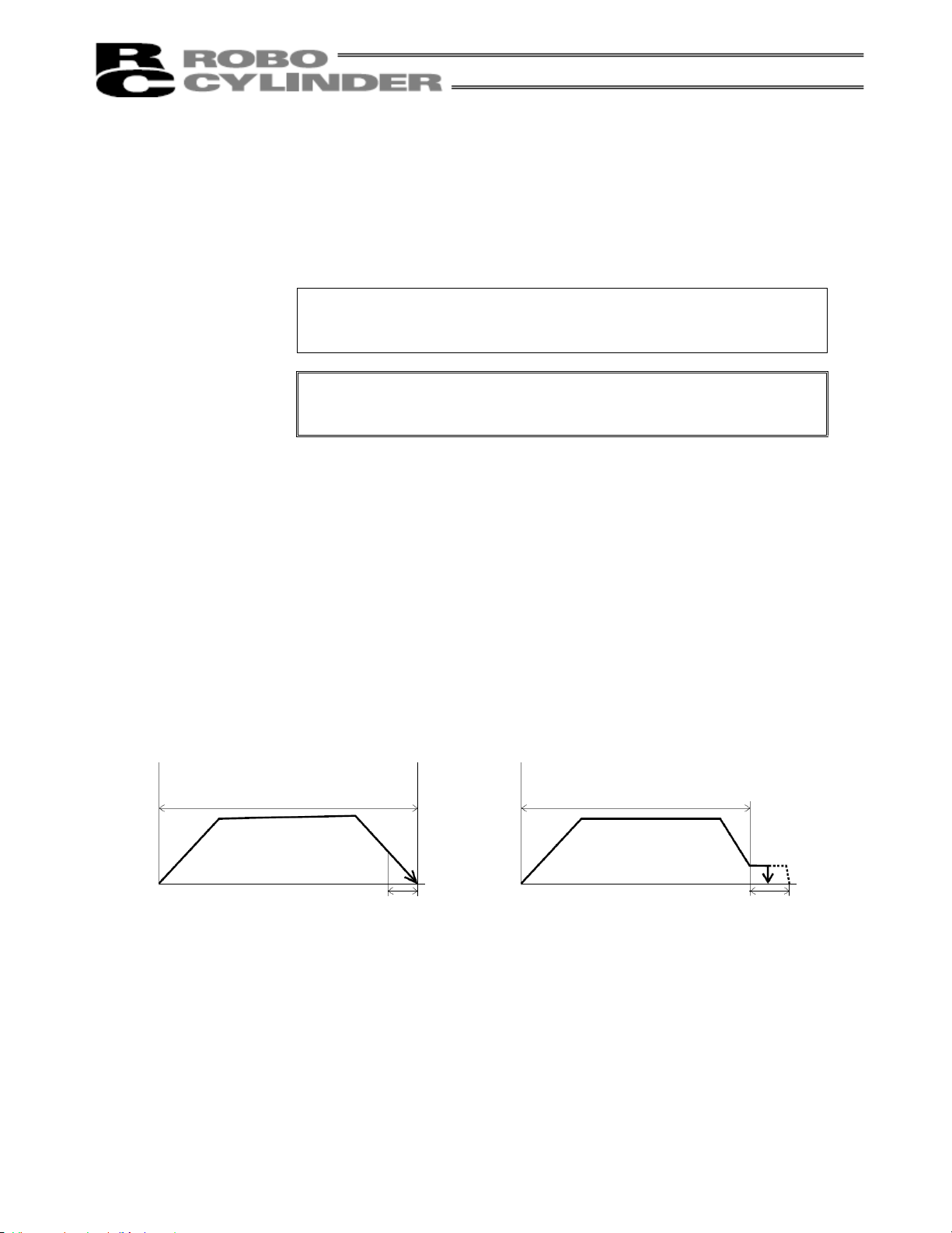
(5) Push (Push)
Select the positioning mode or push & hold mode.
The default value is “0.”
0: Positioning mode (= Normal operation)
Other than 0: Push & hold mode [%]
In the push & hold mode, enter the current-limiting value to be applied to
the servo motor while the load is being pushed. With the RCS, set the
current-limiting value to approx. 70%. The controller will not operate
properly if this value is 30% or below.
The table in 4.1.1, "Push Force at Standstill" lists the push force at
standstill for each controller type when the current-limiting value is set to
70%. Be sure to reference this table.
Note: If the push force is too small, a false detection of push & hold
condition may occur due to slide resistance, etc., so exercise
caution.
(6) Positioning band
(Pos. band)
The function of the positioning band varies depending on whether the
push & hold setting in (5) is “0” or “other than 0.”
[A] Push = 0 (Positioning mode)
In the positioning mode, enter the position-complete detection width
(distance to the target position), in [mm].
The distance to the target position indicates the range prior to the target
position, upon entry of the actuator in which range a position complete
signal will be output.
The default value is “0.1 [mm]” (Fig. A).
[B] Push = Other than 0 (Push & hold mode)
Enter the maximum push amount (distance from the target) in the push
& hold mode, in [mm] (Fig. B).
If the push direction corresponds to the negative direction along the
displayed coordinate axis, add a – (minus) sign to the entered value.
[A] Push = 0
Distance to the position set in (2)
Speed
Fig. A Fig. B
Moving distance
(6) Positioning band
Speed
[B] Push = Other than 0
Distance to the position set in (2)
Moving distance
(6) Positioning band
53
Page 64

(7) Acceleration only MAX
(ACC MAX)
(7) Acceleration only MAX = 0 (7) Acceleration only MAX = 1
Select the specified acceleration or maximum acceleration by entering
“0” or “1.”
The default value is “0.”
0: Specified acceleration --- The value entered in (4) becomes the
actual acceleration/deceleration.
1: Maximum acceleration --- The maximum acceleration set according
to the load is used.
The deceleration conforms to the value
entered in (4).
Acceleration/deceleration
set in (4)
Speed
Moving distance
Maximum acceleration
according to the load
Speed
Acceleration/deceleration
set in (4)
Moving distance
Note: As a rough guide, enable the acceleration only MAX setting when the actual loading capacity is no
more than one-third of the rated loading capacity.
Check the rated loading capacity of your actuator by referring to the supplied specification list of
supported actuators.
54
Page 65

4.1.1 Push Force at Standstill
In the push & hold mode, enter a current-limiting value (%) in the position-data table under “Push.”
With the RCS, use a push force at standstill corresponding to a current-limiting value of approx. 70%.
The push force at standstill can be increased or decreased by increasing or decreasing the current-limiting value.
However, take note that the controller will not operate properly if the current-limiting value is 30% or below.
The table below lists the push force at standstill for each controller type when the current-limiting value is set to
70%.
Type Motor (W) Speed type
RA35 20
RA45 30
60
RA55
100
Rod type
RB7525
RB7530
RB7535
F45 30
Flat type
F55
30
60
60
100
100
150
60
100
L 95 (9.7)
M 47 (4.8)
H 23 (2.4)
L 142 (14.5)
M 70 (7.2)
H 35 (3.6)
L 178 (18.2)
M 89 (9.1)
H 44 (4.5)
L 296 (30.3)
M 149 (15.2)
H 74 (7.6)
L 142 (14.5)
M 70 (7.2)
H 35 (3.6)
M 143 (14.6)
H 71 (7.3)
L 238 (24.3)
M 118 (12.1)
H 59 (6.1)
M 198 (20.2)
H 99 (10.1)
L 296 (30.3)
M 149 (15.2)
H 74 (7.6)
M 222 (22.7)
H 111 (11.4)
L 142 (14.5)
M 70 (7.2)
H 35 (3.6)
L 178 (18.2)
M 89 (9.1)
H 44 (4.5)
L 296 (30.3)
M 149 (15.2)
H 74 (7.6)
Push force
(N (kgf))
Note: The accuracy of push force at standstill is not guaranteed. The values are provided for
reference purposes only.
55
Page 66

4.2 Explanation of Modes
4.2.1 Positioning Mode Push = 0
Speed
Moving distance
4.2.2 Push & Hold Mode Push = Other than 0
(1) Load was contacted successfully
Speed
Note: The time set in the parameter “Push & hold stop judgment period.” The default value of “255 msec” is
already entered.
The actuator is holding the load in position while pushing it.
Warning
The push speed is set as follows in accordance with the speed set in the position-data table:
Push speed 20 mm/sec Set speed
Moving distance
The actuator continues to push the load at the push force at standstill determined by the
current-limiting value. Since the actuator is not inactive, exercise due caution when
handling the machine in this condition.
Position complete signal
Completed position number
Moving OFF
Output
Positioning band
Position complete signal
Completed position number
Moving OFF
Output
Positioning band
20 mm/sec or more Less than 20 mm/sec
(1) The position complete output will turn
ON and moving output will turn OFF at
a position preceding the target position
by the positioning band. A completed
position number signal will be output at
the same time.
(1) After reaching the target position, the actuator
will move at low speed.
When the Pos. band set in the data table (see
Note) is reached after the actuator contacts the
load and the servo motor current has reached
the current-limiting value, the position complete
output will turn ON. A completed position
number signal will be output at the same time.
The moving output will turn OFF.
Set speed
56
Page 67

r
(2) Load was not contacted (missed)
Completed position numbe
Moving OFF
Speed
Moving distance
Positioning band
Output
(3) Load moves during push & hold operation
[1] Load moves in the pushed direction
Position complete signal
Completed position number
Speed
Moving distance
Output
Moving OFF
Positioning band
[2] Load moves in the opposite direction from the push force
(Actuator is pushed back by the reactive force of the load)
Position complete signal
Completed position number
Speed
Moving distance
Output
(1) After reaching the target position, the
actuator will move at low speed.
Even after contacting the load, the actuator
will move to the end of the positioning band
if the servo motor current is yet to reach the
current-limiting value.
The position complete output will not turn
ON even when the end of the positioning
band is reached. In this case, only the
completed position number will be output.
The moving output will turn OFF.
Check if the load has stopped moving based
on whether the moving output has turned
OFF.
If the load moves in the pushed direction after
the position complete output has turned ON
(moving has turned OFF), the actuator will
push the load within the positioning band.
The moving output will turn ON.
The position complete output will remain ON
and the completed position number will be
output continuously.
Once the load stops moving, the moving
output will turn OFF.
If the actuator is pushed back after the position
complete output has turned ON because the
actuator thrust is smaller than the reactive force of
the load, the actuator will be pushed back all the
way until its thrust balances out with the reactive
force of the load.
The position complete output will remain ON and
the completed position number will be output
continuously.
The moving output will remain ON until the load
stops moving.
57
Page 68

(4) Positioning band was entered with a wrong sign
If the positioning band is entered with a wrong sign,
Speed
the position will deviate by twice the positioning
band, as shown to the left, so exercise due caution.
Moving distance
Positioning
band
Positioning
band
4.2.3 Speed Change during Movement
Speed control involving multiple speed levels is possible in a single operation. The actuator speed can be
decreased or increased at a certain point during movement.
However, the position at which to implement each speed change must be set.
Position 1 Position 2 Position 1 Position 2 Position 1 Position 2 Position 3
4.2.4 Operation at Different Acceleration and Deceleration Settings
The actuator will accelerate and decelerate at different speeds if “1” is entered under “Acceleration only MAX” in
the position data.
The acceleration will conform to the maximum acceleration set according to the load, while the deceleration will
conform to the value entered in “Acceleration/deceleration” of the position data.
Maximum acceleration
Note: Although the specific value differs depending on the actuator, the maximum acceleration cannot be more than
Speed
Time
according to the load
three times the rated acceleration.
Accordingly, this function should be enabled only when the transfer weight is no more than one-third of the rated
loading capacity and the actuator needs to be stopped gradually at slow deceleration.
If this function is enabled when the transfer weight is equivalent to the rated loading capacity, an overload error
may occur.
Even if an overload error does not occur, the actuator will still receive excessive impact loads that may negatively
affect the life of the actuator. Therefore, exercise due caution when enabling this function.
Check the rated loading capacity of your actuator by referring to the supplied specification list of supported
actuators.
Deceleration can be set
freely
58
Page 69

4.2.5 Pause
This signal can be used to stop the actuator in case of emergency.
The movement of the actuator can be paused via an external input signal (pause).
For safety reasons, this signal is provided as a contact-b input (based on the negative logic).
The actuator will decelerate to a stop when the pause input is turned OFF, and resume movement when the
pause input is turned ON.
Pause signal
Actuator operation
The remaining movement of the actuator can be cancelled by turning ON the reset input during pause (the
movement will be cancelled upon rise of the reset input signal).
Pause signal
Reset
Actuator operation
4.2.6 Zone Signal Output
This signal is output while the actuator is moving inside a specified zone (the zone can be set in a desired
position).
By setting a zone signal in the applicable parameter beforehand, you can cause the zone signal to turn ON when
the actuator enters the specified zone (the zone can be set in any position, even at the center of the stroke).
Zone signal ON
Zone signal setting range
59
Page 70

4.2.7 Home Return
With the standard specification, home return must be performed after the power has been input or an encoder
open or CPU error alarm has been reset. Selecting a position number and then initiating a start will cause the
controller to automatically perform home return before commencing the subsequent operation. Once home
return is complete, the home return completion output will turn ON (standard specification).
Home return alone cannot be performed using PIO. To move the actuator to the home position in a normal
condition, set a position number for which “0” is set in the position-data table under “Position,” and then issue a
movement command to that position.
With the absolute specification, home return is not necessary after the power has been input, as long as an
absolute reset was performed once.
4.3 Timing Chart
Start
Command position
Position complete
Completed position
Moving
*Pause
Acc/dec Description
T1 Start ON minimum duration
T2 Start OFF minimum duration
T3
T4
T5
T6
T7
T8
T9
T10
*1: The maximum value will vary depending on the acceleration/deceleration.
*2: After the position complete signal turned ON, wait for at least the sequencer’s scan time before checking
Start ON Command position hold time
Start ON Position complete OFF delay
Position complete OFF Moving ON delay
Pause OFF Moving OFF delay
Pause ON Moving ON delay
Position complete ON Moving OFF delay
Completed position OFF Position complete OFF delay
Position complete ON Completed position output delay
the completed position.
Minimum Maximum
4 msec
4 msec
6 msec
0.1 msec 1 msec
0.1 msec
7 msec
1 msec
*1
6 msec
2 msec
1 msec
*2
60
Page 71

4.4 Items to Note on Gripper (RCS-G20)
(1) Finger Operation
[1] Definition of position
The stroke in the specification table indicates a sum of travels of both fingers.
In other words, the travel of each finger is a half of the stroke.
The specified position therefore represents the distance traveled by each finger from its home position
toward the closing side.
[2] Definition of speed and acceleration
Speed and acceleration command values indicate a sum of both fingers.
In other words, the speed or acceleration applicable to each finger is a half of the command value.
[3] Gripper operation mode
If the actuator is used as a gripper to grip the work part, it is recommended to operate the actuator in the
“push mode.”
If the actuator is operated in the “positioning mode,” an overload or deviation overflow error may occur
when the work part is gripped.
[Diagram of Gripping Force Per Finger vs. Current Limit Value]
Gripping force (N)
Current limit value (%)
61
Page 72

5. Using the Controller <Practical Steps>
5-1 How to Start (Standard Specification)
(Refer to 5-2, “How to Execute An Absolute Reset,” for the absolute specification.)
(1) Confirm that both Nos. 1 and 2 of piano switch 2 (SW2) are set to OFF. If these switches are set to ON, tilt
them back to the OFF positions.
(2) Connect the motor/brake cables and encoder cable to the controller.
(3) Connect the host PLC to the PIO connector using the supplied flat cable.
(4) If two or more axes are connected, set the necessary items using the piano switches. For details, refer to
“Names and Functions of Parts.”
(5) Supply the main power to the controller’s terminal block.
Turn ON the pause and servo ON inputs at the PIO connector.
(6)
(7) The controller is working properly if the RDY LED is lit. If the ALM LED is lit, there is an error. Refer to the
alarm table and take an appropriate action.
Note: When the P I/O is powered before main power or when the power source is common, upon
supplying power, the P I/O output may be in an unstable status for approximately 1 msec or less.
As for signal to the Input I/O, please execute after the Position Complete Signal turns ON
after power-up.
The controller is ready once the above operation is completed.
5.1.1 When the Controller Can/Cannot Operate
(1) The moment the power is turned on, the servo turns on. When the controller becomes ready, the PIO
position complete output will turn ON.
(2) The following chart shows the timing relationships of the PIO alarm/emergency-stop outputs and controller’s
operating status.
Emergency stop
Alarm
Reset
Controller
can operate
Emergency-stop
switch is pressed.
Controller
cannot operate
Controller
can operate
Alarm occurs.
Controller
cannot operate
Controller
can operate
62
Page 73

5.2 How to Execute Absolute Reset (Absolute Specification)
Note) With the absolute specification, an encoder receive error (0E5) will occur when the power is turned on
for the first time after the battery or PG cable was disconnected. This does not indicate fault. If this error
occurs, execute an absolute reset by following the specified procedure.
The specific method to execute an absolute reset will vary depending on the controller version.
A label on which a serial number is printed is attached on the right side of the controller.
In the serial number, check the alphabet in the second digit from the last.
Example) SERIAL No. AD251031 J3
In this example, the controller version is “J.”
An absolute reset is executed in different ways on controllers of version J* or earlier (A* to J*) and controllers of
version K* or later (K*, L*, etc.) (* indicates a number).
(If the controller version is K* or later, perform home return from the teaching pendant or PC software when
executing an absolute reset.)
How to Execute an Absolute Reset on a Controller of Version K* or Later
[1] Connect the motor cable and encoder/brake cables to the controller.
[2] Connect the host PLC to the PIO connector using the supplied flat cable.
[3] If two or more axes are connected using a controller link cable, set the address using the piano switches
(SW) on the controller. For details, refer to 2.2, “Names and Functions of Parts” and 3.2, "Names and
Functions of Parts" in this manual.
[4] Turn switch No. 1 (bottom switch) of the controller’s piano switches 2 (SW2) to ON (tilt to the right).
[5] Turn on the main controller power.
[6] Connect the battery to the controller.
[7] The ALM LED will illuminate.
[8] Turn ON the pause and servo ON input signals at the PIO connector.
[9] Input a reset signal via the PIO connector to reset the alarm.
[10] Perform home return from the teaching pendant or PC software.
[11] Turn switch No. 1 of the controller’s piano switches 2 (SW2) to OFF (tilt to the left).
An absolute reset has been executed.
63
Page 74

How to Execute an Absolute Reset on a Controller of Version J* or Earlier
[1] Connect the motor and encoder/brake cables to the controller.
[2] Connect the host PLC to the PIO connector using the supplied flat cable.
[3] If two or more axes are connected, set the address using SW1 on the controller. For details, refer to 2.2,
“Names and Functions of Parts” and 3.2, "Names and Functions of Parts"
[4] Move the actuator slider or rod to a position where it is in contact with the mechanical end on the home
side.
[5] Turn switch No. 1 (bottom switch) of the controller’s SW2 to ON (tilt to the right).
[6] Turn on the main controller power.
[7] Connect the battery to the controller.
[8] The RDY LED will illuminate.
[9] Turn switch No. 1 of the controller’s SW2 to OFF (tilt to the left). Note 1)
An absolute reset has been executed. The home has been set several millimeters ahead of the current
position (mechanical end) (the specific distance from the mechanical end will vary depending on the
actuator model).
[10] To operate the actuator right away, turn ON the PIO pause/servo ON inputs.
Note 1) If switch No. 1 of SW2 remains ON, the next time the power is turned on an absolute reset will be
executed based on the actuator position at that time.
Note 1) The absolute RCS controller can be used only with absolute RCS actuators. It cannot be used
with standard RCS actuators.
64
Page 75

5.3 Movement after Power On (Standard Type)
Example of use in operation) After the power is turned on, move the actuator to the position 150 mm from the
No. Position Speed
0 0 100 0.3 0 0.1 0
1 150 200 0.3 0 0.1 0
P
L
C
[7] [4]
[3]
[2]
[1]
[10]
[9] [5]
[8]
[11] [6]
Signal name
Start
Command position 1
Command position 2
Command position 4
Command position 8
* Pause
Reset
Servo ON
Completed position 1
Completed position 2
Completed position 4
Completed position 8
Position complete
Home return completion
Zone
* Alarm
* Emergency stop
Moving
With the absolute specification, the home
return completion signal will turn ON after
the power is turned on, and the actuator will
move directly to position 1 without
performing home return.
home at a speed of 200 mm/sec.
Position-data table (Field(s) within thick line must be entered.)
Acceleration/
deceleration
Push Positioning band
RCS controller
PIO
Reference flow
Power ON
Category
Servo ON input ON
[1]
Pause input ON
[2]
Select/enter command position 1.
Input
Output
[3]
Start input ON
[4]
Home return starts.
Position complete output OFF
[5]
Moving output ON
[6]
Start input OFF
[7]
Home return completes.
Home return completion output ON
[8]
Movement to position 1 starts.
Position complete output turns ON 0.1 mm
[9]
before position 1.
[10]
Completed position 1 is output.
Moving output OFF
[11]
Movement to position 1 completes.
Acceleration
only MAX
65
Page 76

A
Command position
Power ON
Servo ON
Start
Position 1
Note
Position complete
Emergency stop
Completed position
* Home return
*Actuator movement
Pause
Alarm
completion
Speed
Moving
Position 1
Positioning band
Time
The position complete output will turn ON when the controller becomes ready following the power ON. (The
position complete output will not turn ON if the servo ON input is OFF.)
To check if the controller is ready, always check if the position complete output is ON.
All completed position outputs are OFF immediately after the power is turned on. When the commanded
movement is complete, the completed position will be output. If the movement command was to position No. 0,
all of the completed positions will remain OFF.
The actuator will not operate unless the pause input is turned ON.
T1: 5 msec or more; time after selecting/entering a command position until the start input turns ON
(The scan time of the host controller must be considered.)
* With the absolute specification, the home return completion signal will turn ON after the power is turned on,
and home return will not be performed.
Note: When the start signal turns ON, the position complete output will turn OFF and the moving
output will turn ON.
The start signal must be turned OFF with the confirmation that the moving output has turned
ON while the start signal remains ON.
If the start input remains ON as shown below, the position complete output will not turn ON
even when the actuator movement is completed. The moving output will not turn OFF, either.
Position complete
Start
Moving
ctuator
1 msec or less
66
Page 77
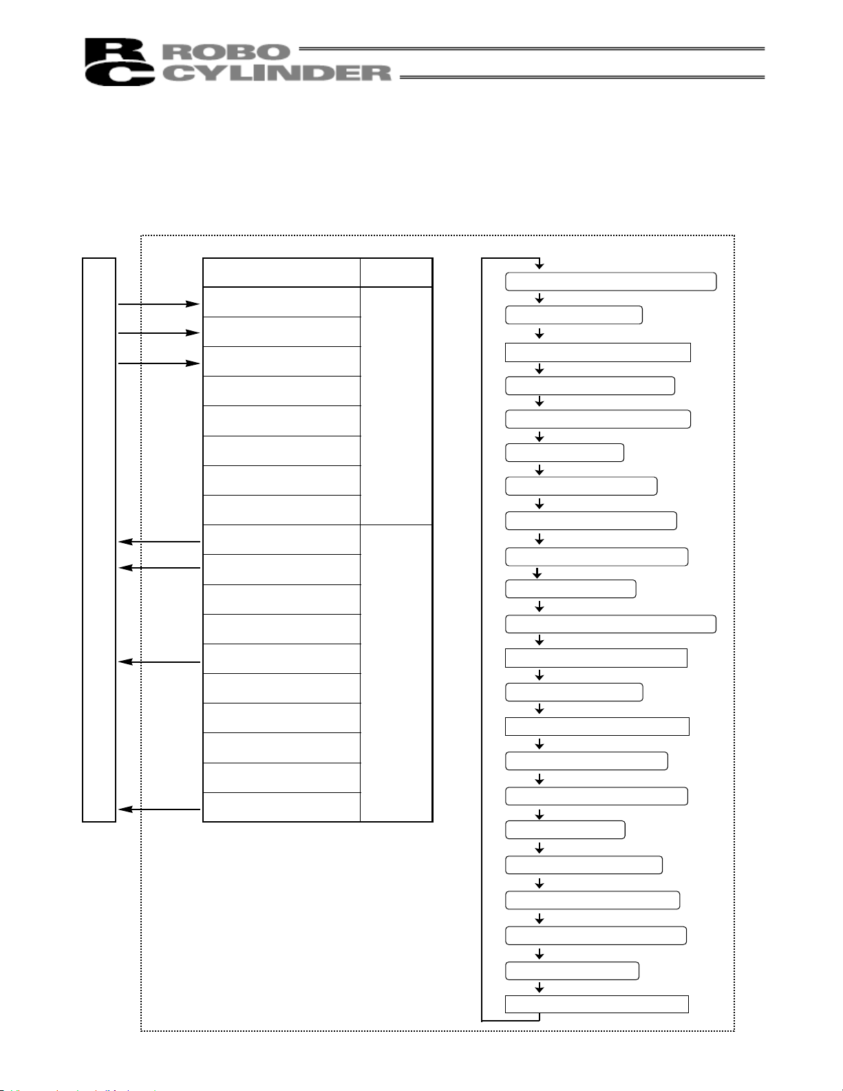
5.4 Positioning Mode (Back and Forth Movement between Two Points)
Example of use in operation) The actuator moves back and forth between two positions. The position 250 mm
from the home is set as position 1, and the position 100 mm from the home is set
as position 2. The travel speed to position 1 is set as 200 mm/sec, and to position
P
L
C
[13] [10] [5] [2]
[1]
[9]
[7]
[15]
[14] [11] [6] [3]
[16] [12] [8] [4]
Signal name
Start
Command position 1
Command position 2
Command position 4
Command position 8
* Pause
Reset
Servo ON
Completed position 1
Completed position 2
Completed position 4
Completed position 8
Position complete
Home return completion
Zone
* Alarm
* Emergency stop
Moving
2 is set as 100 mm/sec.
RCS controller
PIO
Category
Input
Output
Reference flow
Select/enter command position 1.
[1]
[2]
Start input ON
Movement to position 1 starts.
Completed position OFF
[3]
Position complete output OFF
[4]
Moving output ON
[5]
Start input OFF
Position complete output ON
[6]
[7]
Completed position 1 is output.
Moving output OFF
[8]
[9]
Select/enter command position 2.
Movement to position 1 completes.
Start input ON
[10]
Movement to position 2 starts.
Completed position OFF
[11]
Position complete output OFF
Moving output ON
[12]
Start input OFF
[13]
[14]
Position complete output ON
Completed position 2 is output.
[15]
Moving output OFF
[16]
Movement to position 2 completes.
67
Page 78

No. Position Speed
0 * * * * * *
1 250 200 0.3 0 0.1 0
2 100 100 0.3 0 0.1 0
Position-data table (Field(s) within thick line must be entered.)
Acceleration/
deceleration
Push Positioning band
Acceleration
only MAX
Command position
Position complete
Moving
Completed position
Actuator movement
Start
Speed
Position 1 Position 2 Position 1
Note Note Note
Position 1 Position 2 Position 1
T1: 5 msec or more; time after selecting/entering a command position until the start input turns ON
(The scan time of the host controller must be considered.)
Each command position must be input after the position complete output has turned ON for the movement to the
previous position.
Note: When the start signal turns ON, the position complete output will turn OFF and the moving
output will turn ON.
The start signal must be turned OFF with the confirmation that the moving output has turned
ON while the start signal remains ON.
If the start input remains ON as shown below, the position complete output will not turn ON
even when the actuator movement is completed. The moving output will not turn OFF, either.
Position complete
Start
Moving
Actuator
1 msec or less
68
Page 79

5.5 Push & Hold Mode
Example of use in operation) The actuator is caused to move back and forth in the push & hold mode and
Movement to position 1 is performed in the push & hold mode (the actuator is caused
P
L
C
[13] [10] [5] [2]
[1]
[9]
[7]
[15]
[14] [11] [6] [3]
[16] [12] [8] [4]
Signal name
Start
Command position 1
Command position 2
Command position 4
Command position 8
* Pause
Reset
Servo ON
Completed position 1
Completed position 2
Completed position 4
Completed position 8
Position complete
Home return completion
Zone
* Alarm
* Emergency stop
Moving
positioning mode. The position 280 mm from the home is set as position 1, and the
position 40 mm from the home is set as position 2.
to contact the load and push it in the counter-motor direction). The maximum push
amount at position 1 is set as 15 mm, and the current-limiting value during the push &
hold operation by the servo motor is set as 50%. Movement to position 2 is performed
in the positioning mode. The travel speed to position 1 is set as 200 mm/sec, and that
to position 2 is set as 100 mm/sec.
RCS controller
PIO
Category
Input
Output
Reference flow
Select/enter command position 1.
[1]
Start input ON
[2]
Movement to position 1 starts.
Completed position OFF
[3]
Position complete output OFF
[4]
Moving output ON
Start input OFF
[5]
Move at slow speed after passing position 1.
Load is pushed. Servo motor current rises to
the current-limiting value.
[6]
Position complete output ON
Completed position 1 is output.
[7]
Moving output OFF
[8]
Select/enter command position 2.
[9]
Start input ON
[10]
Movement to position 2 starts.
Completed position OFF
[11]
Position complete output OFF
Moving output ON
[12]
Start input OFF
[13]
Position complete output turns ON 0.1
[14]
mm before position 2.
Completed position 2 is output.
[15]
Moving output OFF
[16]
Movement to position 2 completes.
69
Page 80

No. Position Speed
0 * * * * * *
1 280 200 0.3 50 15 0
2 40 100 0.3 0 0.1 0
Position-data table (Field(s) within thick line must be entered.)
Acceleration/
deceleration
Push Positioning band
Acceleration
only MAX
Command position
Position complete
Moving
Completed position
Actuator movement
Start
Speed
Position 1 Position 2 Position 1
Note Note Note
Position 1 Position 2 Position 1
T1: 5 msec or more; time after selecting/entering a command position until the start input turns ON
(The scan time of the host controller must be considered.)
Each command position must be input after the position complete output has turned ON for the movement to the
previous position.
Note: When the start signal turns ON, the position complete output will turn OFF and the moving
output will turn ON.
The start signal must be turned OFF with the confirmation that the moving output has turned
ON while the start signal remains ON.
If the actuator has missed the load, the position complete output will not turn ON as shown
below. The completed position will be output and the moving output will turn OFF.
Command position
Position complete
Completed position
Actuator movement
Start
Moving
Speed
Position 1 Position 2 Position 1
Position 1 Position 2 Position 1
70
Page 81

5.6 Speed Change during Movement
Example of use in operation) The actuator speed is reduced at a certain point during movement.
The position 150 mm from the home is set as position 1, and the position 200 mm
Method) In this example, the actuator is caused to move to position 1 and to position 2
P
L
C
[11] [9] [5] [2]
[1]
[6]
[8]
[13]
[12] [10] [7] [3]
[14] [4]
Signal name
Start
Command position 1
Command position 2
Command position 4
Command position 8
* Pause
Reset
Servo ON
Completed position 1
Completed position 2
Completed position 4
Completed position 8
Position complete
Home return completion
Zone
* Alarm
* Emergency stop
Moving
from the home is set as position 2. The actuator is initially located between the home
and position 1. The actuator is moved to position 2 being the target position, at a travel
speed of 200 mm/sec to position 1 and that of 100 mm/sec from position 1 to position
2.
successively. Before the actuator is stopped at position 1, command position 2 must
be selected/entered and the start signal must be input. To do this, set a wide
positioning band at position 1 and cause the start signal for movement to position 2 to
be input immediately after the completion signal for movement to position 1 is output.
(Command position 2 should be entered while the actuator is moving to position 1.)
RCS controller
PIO
Category
Reference flow
Select/enter command position 1.
[1]
Start input ON
[2]
Movement to position 1 starts at 200 mm/sec.
Completed position OFF
Position complete output OFF
Input
Output
[3]
Moving output ON
[4]
Start input OFF
[5]
Select/enter command position 2.
[6]
Position complete output turns ON
[7]
1 mm before position 1.
Completed position 1 is output.
[8]
Start input ON
[9]
Movement to position 2 starts at 100 mm/sec.
Completed position OFF
Position complete output OFF
[10]
[11]
[12]
[13]
[14]
Start input OFF
Position complete output turns ON
0.1 mm before position 2.
*
Completed position 2 is output.
Moving output OFF
Movement to position 2 completes.
71
Page 82

No. Position Speed
0 * * * * * *
1 150 200 0.3 0 1 0
2 200 100 0.3 0 0.1 0
Position-data table (Field(s) within thick line must be entered.)
Acceleration/
deceleration
Push Positioning band
Acceleration
only MAX
Command position
Position complete
Completed position
Actuator movement
Start
Moving
Speed
Position 1 Position 2
Note Note
Position 2
Position 1
T1: 5 msec or more; time after selecting/entering a command position until the start input turns ON
(The scan time of the host controller must be considered.)
Note: When the start signal turns ON, the position complete output will turn OFF and the moving
output will turn ON.
The start signal must be turned OFF with the confirmation that the moving output has turned
ON while the start signal remains ON.
72
Page 83

5-7 Operation at Different Acceleration and Deceleration Settings
Example of use in operation) Positioning is performed to the position 150 mm from the home (position 1) at a
speed of 200 mm/sec. The actuator will accelerate at the maximum acceleration
set according to the load, and decelerate at 0.1 G.
Method) Entering “1” under “Acceleration only MAX” in the position data will automatically
adjust the acceleration to the maximum acceleration set according to the load.
Entering “0.1” under “Acceleration/deceleration” in the position data will set the
P
L
C
[5] [2]
[1]
[7]
[6] [3]
[8] [4]
Signal name
Start
Command position 1
Command position 2
Command position 4
Command position 8
* Pause
Reset
Servo ON
Completed position 1
Completed position 2
Completed position 4
Completed position 8
Position complete
Home return completion
Zone
* Alarm
* Emergency stop
Moving
deceleration to 0.1 G.
PIO
Category
Input
Output
RCS controller
[1]
[2]
[3]
[4]
[5]
[6]
[7]
[8]
Reference flow
Select/enter command position 1.
Start input ON
Movement to position 1 starts at the maximum
acceleration.
Completed position OFF
Position complete output OFF
Moving output ON
Start input OFF
Moves at constant speed (200 mm/sec).
Decelerates at 0.1 G.
Position complete output turns ON
0.1 mm before position 1.
Completed position 1 is output.
Moving output OFF
Movement to position 1 completes.
73
Page 84

A
No. Position Speed
0 * * * * * *
1 150 200 0.1 0 0.1 1
Position-data table (Field(s) within thick line must be entered.)
Acceleration/
deceleration
Push Positioning band
Acceleration
only MAX
Command position
Position complete
Completed position
Actuator movement
Start
Moving
Speed
Position 1
Position 1
Positioning band
T1: 5 msec or more; time after selecting/entering a command position until the start input turns ON
(The scan time of the host controller must be considered.)
Note: When the start signal turns ON, the position complete output will turn OFF and the moving
output will turn ON.
The start signal must be turned OFF with the confirmation that the moving output has turned
ON while the start signal remains ON.
If the start input remains ON as shown below, the position complete output will not turn ON
even when the actuator movement is completed. The moving output will not turn OFF, either.
Position complete
Start
Moving
ctuator
1 msec or less
If an overload alarm occurs frequently when this function is used, disable the “acceleration only
MAX” function.
74
Page 85

5.8 Pause
Example of use in operation) The actuator is paused during movement.
Method) Use the pause input.
RCS controller
P
L
C
[5] [2]
[1]
[8] [6]
[11]
[10] [3]
[12] [9] [7] [4]
Signal name
Start
Command position 1
Command position 2
Command position 4
Command position 8
* Pause
Reset
Servo ON
Completed position 1
Completed position 2
Completed position 4
Completed position 8
Position complete
Home return completion
Zone
* Alarm
* Emergency stop
Moving
PIO
Category
Input
Output
Reference flow
Select/enter a desired command position.
[1]
Start input ON
[2]
Movement to the selected position starts.
Completed position OFF
Position complete output OFF
[3]
Moving output ON
[4]
Start input OFF
[5]
Pause input OFF (Actuator
[6]
decelerates to a stop.)
Moving output OFF
[7]
Pause input ON (Movement starts.)
[8]
Moving output ON
[9]
Position complete output ON
[10]
Completed position is output.
[11]
Moving output OFF
[12]
Movement to the selected position
completes.
75
Page 86

Command position
Start
Position complete
Completed position
Pause
Moving
Speed
Actuator movement
Note
4 msec or less
T1: 5 msec or more; time after selecting/entering a command position until the start input turns ON
(The scan time of the host controller must be considered.)
Note: When the start signal turns ON, the position complete output will turn OFF and the moving
output will turn ON.
The start signal must be turned OFF with the confirmation that the moving output has turned
ON while the start signal remains ON.
The remaining movement can be cancelled by turning ON the reset input during pause.
(The controller will detect a rise of the reset signal and cancel the remaining movement.)
Command position
Start
Position complete
Completed position
Pause
Reset
Moving
Speed
Actuator movement
4 msec or more
76
Page 87

A
5.9 Zone Signal Output
Example of use in operation) While the actuator is moving a zone signal is output inside the zone enclosed by
distances of 40 mm and 120 mm from the home. (40 mm Zone signal output
120 mm)
Method) Use the parameters “Zone boundary+” and “Zone boundary–” to set the zone in
P
L
C
[5] [2]
[1]
[9]
[8] [3]
[7] [6]
[10] [4]
Signal name
Start
Command position 1
Command position 2
Command position 4
Command position 8
* Pause
Reset
Servo ON
Completed position 1
Completed position 2
Completed position 4
Completed position 8
Position complete
Home return completion
Zone
* Alarm
* Emergency stop
Moving
which the zone signal is output, as shown below:
Zone boundary+ 120
Zone boundary– 40
RCS controller
PIO
Category
Input
Output
Reference flow
Select/enter a desired command position.
[1]
Start input ON
[2]
Movement to the selected position starts.
Completed position OFF
Position complete output OFF
[3]
Moving output ON
[4]
Start input OFF
[5]
Actuator enters the zone. Zone output ON
[6]
[7]
[8]
[9]
ctuator exits the zone. Zone output
OFF
Position complete output ON
Completed position is output.
Moving output OFF
[10]
Movement to the selected position
completes.
77
Page 88

Command position
Position complete
Completed position
Actuator movement
Moving
Start
Zone
Speed
Note
T1: 5 msec or more; time after selecting/entering a command position until the start input turns ON
(The scan time of the host controller must be considered.)
Note: When the start signal turns ON, the position complete output will turn OFF and the moving
output will turn ON.
The start signal must be turned OFF with the confirmation that the moving output has turned
ON while the start signal remains ON.
Example of other zone output)
Zone output at 120 or more Zone output at 40 or less
Zone
Zone
Zone boundary+ Maximum stroke length Zone boundary+ 40
Zone boundary– 120 Zone boundary– 0
78
Page 89

5.10 Returning Home
Example of use in operation) Home return alone cannot be performed using PIO.
Method) Create point data of 0 distance from the home, and move the actuator to that
position.
Enter home data in position 0. To return home, move the actuator to position 0.
Position-data table (Field(s) within thick line must be entered.)
No. Position Speed
0 0 100 0.3 0 0.1 0
1 * * * * * *
Acceleration/
deceleration
P
L
C
[5] [2]
[1]
[6] [3]
[7] [4]
Signal name
Start
Command position 1
Command position 2
Command position 4
Command position 8
* Pause
Reset
Servo ON
Completed position 1
Completed position 2
Completed position 4
Completed position 8
Position complete
Home return completion
Zone
* Alarm
* Emergency stop
Moving
PIO
Category
Input
Output
Push Positioning band
RCS controller
[1]
[2]
[3]
[4]
[5]
[6]
[7]
Acceleration
only MAX
Reference flow
Select/enter a desired command
position. (Command positions 1, 2, 4
and 8 are all OFF)
Start input ON
Movement to position 0 (home) starts.
Completed position OFF
Position complete output OFF
Moving output ON
Start input OFF
Position complete output turns ON 0.1
mm before position 0.
Moving output OFF
Movement to position 0 completes.
79
Page 90

Command position
Start
Position complete
Completed position
Moving
Speed
Actuator movement
Position 0
Note
Turn all of command positions
1, 2, 4 and 8 OFF.
Completed positions 1,
2, 4 and 8 all turn OFF.
T1: 5 msec or more; time after selecting/entering a command position until the start input turns ON
(The scan time of the host controller must be considered.)
Data of 0 distance from the home need not be always entered in position 0.
In this example, data of 0 distance from the home was entered in position 0. Of course, such data can also be
entered in any other position of 1 to 15.
Note: When the start signal turns ON, the position complete output will turn OFF and the moving
output will turn ON.
The start signal must be turned OFF with the confirmation that the moving output has turned
ON while the start signal remains ON.
If the start input remains ON as shown below, the position complete output will not turn ON
even when the actuator movement is completed. The moving output will not turn OFF, either.
Position complete
Start
Moving
Actuator
1 msec or less
80
Page 91

5.11 Incremental Moves
Example of use in operation) The actuator is caused to move from the home to the 30-mm position, from which it
will be moved repeatedly in increments of 10 mm. The travel speed from the home to
the 30-mm position is set as 100 mm/sec, and that for 10-mm incremental moves is
P
L
C
[13] [10] [5] [2]
[1]
[9]
[7]
[15]
[14] [11] [6] [3]
[16] [12] [8] [4]
Signal name
Start
Command position 1
Command position 2
Command position 4
Command position 8
* Pause
Reset
Servo ON
Completed position 1
Completed position 2
Completed position 4
Completed position 8
Position complete
Home return completion
Zone
* Alarm
* Emergency stop
Moving
set as 20 mm/sec.
PIO
Category
RCS controller
Input
Output
Reference flow
Select/enter command position 1.
[1]
Start input ON
[2]
Movement to position 1 starts.
Completed position OFF
[3]
Position complete output OFF
Moving output ON
[4]
Start input OFF
[5]
Position complete output ON
[6]
Completed position 1 is output.
[7]
Moving output OFF
[8]
Movement to position 1 completes.
Select/enter command position 2.
[9]
Start input ON
[10]
Movement to +10 mm from the current position starts.
Completed position OFF
Position complete output OFF
[11]
[12]
Moving output ON
[13]
Start input OFF
Position complete output ON
[14]
Completed position 2 is output.
[15]
Moving output OFF
[16]
Movement to the +10 mm position completes.
81
Page 92

No. Position Speed
0 * * * * * *
1 30 100 0.3 0 0.1 0
2
=
10 20 0.3 0 0.1 0
Position-data table (Field(s) within thick line must be entered.)
Acceleration/
deceleration
Push Positioning band
Acceleration
only MAX
Command position
Position complete
Completed position
Actuator movement
Start
Moving
Speed
Position 1 Position 2
Note 1
Position 1
Position 2
Note 2
Position 2
Time
Distance from home
T1: 5 msec or more; time after selecting/entering a command position until the start input turns ON
(The scan time of the host controller must be considered.)
Note 1: When the start signal turns ON, the position complete output will turn OFF and the moving
output will turn ON.
The start signal must be turned OFF with the confirmation that the moving output has turned
ON while the start signal remains ON.
If the start input remains ON as shown below, the position complete output will not turn ON
even when the actuator movement is completed. The moving output will not turn OFF, either.
Position complete
Start
Moving
Actuator
1 msec or less
Note 2: When a soft limit is reached as a result of repeated incremental moves, the actuator will stop
at that position and the position complete signal will be output.
82
Page 93

5.12 Notes on Incremental Mode
(1) Notes on positioning operation
Selecting/entering a position number using relative coordinates during positioning will cause the actuator to
move to the position corresponding to the initial position plus the increment. (If the increment is a negative
value, the actuator will move to the position corresponding to the initial position minus the increment.)
Example) If the start signal for movement to position 2 is input while the actuator is moving to position 1,
the actuator will move to the position 40 mm from the home.
Command position
Start
Position complete
Completed position
Moving
Speed
Actuator movement
If the start signal for movement to an incremental position number is input multiple times during positioning,
the actuator will move to the position corresponding to the initial position plus the “increment x number of
times the signal was input.”
Example) If the start signal for movement to position 2 is input twice while the actuator is moving to
position 1, the actuator will move to the position 50 mm from the home.
Command position
Start
Position complete
Completed position
Actuator movement
Moving
Speed
(2) Note on push & hold operation
If the start signal is input with an incremental position number selected/entered while the actuator is moving
in the push & hold mode, the actuator will move to the position corresponding to the position at the time of
start input plus the increment. Therefore, the end position will become indeterminate.
Position 1 Position 2
Position from home: 40
Position 1 Position 2
Position from home: 50
Position 2
Distance
Position 2
Distance
No. Position Speed
0 * *
1 30 100
2
10 100
=
83
Page 94

Example) If the start signal for movement to position 2 is input while the actuator is moving to position 1
in the push & hold mode, the actuator will move to the position 10 mm from where it was when
the input signal was input.
Command position
Position complete
Completed position
Actuator movement
Start
Speed
Position 1 Position 2
10 mm
Position 2
Distance
No. Position Speed
0 * *
1 50 100
2
10 100
=
(3) Cumulative errors due to repeated incremental moves
Position data is recognized only as a multiple of the minimum resolution. The minimum resolution is
determined by the lead and the number of encoder pulses. Therefore, a margin of error may occur between
the entered position value and the actual movement of the actuator. If an incremental move is repeated, this
error will accumulate.
The maximum error range for each actuator type is shown below:
Type
SA4 20
SA5 20
Slider
type
type
SA6 30
SSR 60
SMR
F45 30
Flat
F55
Motor
(W)
100
150
60
100
Speed
type
M 5 0.3 M 5 0.6
H 10 0.6
M 6 0.4 M 5 0.3
H 12 0.7
M 6 0.4 M 8 0.5
H 12 0.7
M 6 0.4 L 4 0.2
H 12 0.7 M 8 0.5
M 10 0.6
H 20 1.2 M 5 1.6
M 10 0.6
H 20 1.2 L 3 1.0
M 5 0.3
H 10 0.6 M 6 2.0
M 8 0.5 L 4 1.3
H 16 1.0 M 8 2.6
M 8 0.5 M 8 2.6
H 16 1.0
Screw
lead (mm)
L 2.5 0.2 L 2.5 0.3
L 3 0.2 L 2.5 0.2
L 3 0.2 L 4 0.2
L 2.5 0.2 M 6 2.0
L 4 0.2
L 4 0.2
Maximum
error ()
Type
RA35 20
RA45 30
RA55
Rod
type
RB7525 60
RB7530
RB7535
Motor
(W)
60
100
60
100
100
150
Speed
type
H 10 1.2
H 10 0.6
H 16 1.0
H 16 1.0
H 10 3.3
H 12 3.9
H 12 3.9
H 16 5.2
H 16 5.2
Screw
lead (mm)
Maximum
error ()
84
Page 95

6. Parameters
6.1 Parameter Classification
The parameters are classified into the following four types depending on their function:
Types:
a: Parameter relating to actuator stroke range
b: Parameter relating to actuator operating characteristics
c: Parameter relating to external interface
d: Servo gain adjustment
6.2 Parameter List
No. Type Name Unit Factory default
1 a Zone limit + side mm Effective actuator length
2 a Zone limit – side mm Effective actuator length
3 a Soft limit + side mm Effective actuator length
4 a Soft limit – side mm Effective actuator length
5 a Home direction [0: Reverse/1: Forward] - (In accordance with the ordered specification.)
6 b Push & hold recognition time msec 255
7 d Servo gain No. -
8 b Initial speed setting
9 b Initial acceleration/deceleration setting G
10 b Initial positioning band (in-position) mm 0.10
11 b Initial acceleration only MAX flag - 0
12 b
13 b Current limit value during homing %
14 b Movement flag during stop - 1
15 c
16 c Serial communication speed bps 38400
17 c
18 Reserved -
19 Reserved -
20 Reserved -
21 c
22 a Home offset mm
Current limit value during positioning
stop
Hold input disable selection [0: Enable/1:
Disable]
Minimum delay before slave transmitter
activation
Servo ON input disable selection [0:
Enable/1: Disable]
mm/sec Set individually depending on the actuator characteristics.
msec 5
(Note) The numbers are shown on the PC software screen, but not on the teaching pendant.
The type symbols are given for convenience and not shown on the PC software screen or teaching pendant.
Set individually depending on the actuator characteristics.
Set individually depending on the actuator characteristics.
Set individually depending on the actuator characteristics.
%
Set individually depending on the actuator characteristics.
- 0
- 0
Set individually depending on the actuator characteristics.
85
Page 96

A
A
A
A
6.3 Parameter Settings
If you have changed any parameter, be sure to restart the controller via a software reset or reconnect the
controller power.
6.3.1 Parameters Relating to Actuator Stroke Range
Soft limits
Set the + soft limit in parameter No. 3 and - soft limit in parameter No. 4.
Both parameters have been set to the effective actuator length at the factory. Change the parameter settings if
necessary, such as when an obstacle is present and collision between the actuator and obstacle must be
prevented or when the actuator must be operated beyond the effective length.
Exercise due caution when setting these parameters, as wrong settings will cause collision with the mechanical
end.
The minimum setting unit is 0.01 mm.
(Note) To change these parameters, set values corresponding to positions that are 0.3 mm wider than the
desired effective range.
Example) Set the effective range to between 0 and 80 mm
Parameter No. 3 (+ side): 80.3
Parameter No. 4 (– side): -0.3
pproximately
0.3 mm
pproximately
0.1 mm
Zone limits
Set the zone in which the zone output signal turns ON.
The zone signal will turn ON when the current coordinate is between the – setting and + setting.
Set the + zone limit in parameter No. 1 and – zone limit in parameter No. 2.
The minimum setting unit is 0.01 mm.
Example) With the actuator of 300-mm stroke, use the zone limits as an intermediate LS actuating in a range
of 100 to 200 mm
Parameter No. 1 (+ side): 200 Parameter No. 2 (– side): 100
(Home)
Home direction
If not specified by the user, the home direction is set to the motor side before shipment.
If you must change the home direction after the actuator has been assembled to your equipment, switch 0 and 1
in the setting of parameter No. 5.
If necessary, also change the home offset and soft limits.
Caution: Rod-type actuators do not permit reversing of the home direction.
If the home direction is reversed, all position data currently input will be cleared.
Soft limit set in the controller
Effective\e territory
JogIncrement movable range upon homing
Zone output turns ON.
pproximately
0.3 mm
pproximately
0.1 mm
86
Page 97

Home offset
Parameter No. 22 has been set to an optimal value at the factory so that the distance from the mechanical end
to home will remain constant.
The minimum setting unit is 0.01 mm.
This parameter can be adjusted in the following conditions:
[1] Align the actuator’s home with the mechanical home on the equipment after the actuator has been
assembled to the equipment.
[2] Set the home position again after reversing the factory-set home direction.
[3] Correct the minor position deviation that has generated after the actuator was replaced.
Caution: If you have changed the home offset, the soft limit parameters must also be reviewed.
6.3.2 Parameters Relating to Actuator Operating Characteristics
Initial speed setting
This parameter has been set to the rated speed of the actuator at the factory.
If a target position was written to an unregistered position table or the current position was acquired in the
teaching mode, the controller regards the value of this parameter as the speed data corresponding to the
applicable position number.
To set a speed lower than the rated speed, change the setting of parameter No. 8.
Initial acceleration/deceleration setting
This parameter has been set to the rated acceleration/deceleration of the actuator at the factory.
If a target position was written to an unregistered position table or the current position was acquired in the
teaching mode, the controller regards the value of this parameter as the acceleration/deceleration data
corresponding to the applicable position number.
To set an acceleration/deceleration lower than the rated acceleration/deceleration, change the setting of
parameter No. 9.
Initial positioning band (in-position)
This parameter has been set to “0.10” mm at the factory.
If a target position was written to an unregistered position table or the current position was acquired in the
teaching mode, the controller regards the value of this parameter as the positioning band data corresponding to
the applicable position number.
Since increasing this value will cause a position complete signal to output early, change the setting of parameter
No. 10 as necessary.
Initial acceleration only MAX flag
To cause the actuator to stop gradually at slow deceleration, you must set a lower acceleration/deceleration.
However, this will also slow the acceleration.
This parameter lets you set a quicker acceleration without affecting the deceleration.
Note, however, that this parameter can be used only when the actual payload is no more than one-third of the
rated loading capacity.
Check the rated loading capacity of your actuator by referring to the supplied specification list of supported
actuators.
This parameter has been set to “0” (Disable) at the factory.
If a target position was written to an unregistered position table or the current position was acquired in the
teaching mode, the controller regards the value of this parameter as the “acceleration only MAX” data
corresponding to the applicable position number.
To enable this function, change parameter No. 11 to “1” (Enable).
87
Page 98

Push & hold recognition time
This parameter is used as a condition for determining if the actuator has contacted the work part and completed
its push-mode operation.
Specifically, push-mode operation is deemed complete if the current limit value set in the position table has been
maintained for the time set in parameter No. 6.
Set this parameter to an optimal value in accordance with the current limit value, by considering the shape and
strength of the work part, etc.
The minimum setting unit is 1 msec, and the maximum value is 255 msec. This parameter has been set to “255”
msec at the factory.
(Note) If the work part has shifted and current has changed during the push & hold recognition time, the
judgment will be made as follows. In this example, the push & hold recognition time is set to 255 msec.
Push current
Start position Target position Counting starts
Count to 200
Decrement to 180
Count to 255
Completion of push-mode operation is recognized.
If the push current is maintained for 200 msec and then drops for 20 msec thereafter, the counter is
decremented by 20. Upon recovery of the push current, counting resumes from 180. If the push current is
maintained for 75 msec, the counter will have counted up to 255 and thus the controller will recognize
completion of push-mode operation.
In this case, the judgment requires a total of 295 msec.
Current limit value during positioning stop
At the factory, this parameter has been set to a current value corresponding to the standard specification of the
actuator.
Increasing this value will increase the holding torque while the actuator is stopped.
This parameter need not be changed in normal conditions of use. However, hunting will occur if excessive
external force applies to the actuator while the actuator is stopped. In this case, the value set in parameter No.
12 must be increased.
If you need to change this parameter, please contact IAI first.
Current limit value during homing
At the factory, this parameter has been set to a current value corresponding to the standard specification of the
actuator.
Increasing this value will increase the torque during homing.
This parameter need not be changed in normal conditions of use. However, the value set in parameter No. 13
must be increased if the slide resistance has increased in a vertical application due to the affixing method, load
condition, etc., and homing completes before the correct position.
If you wish to change this parameter, please contact IAI first.
88
Page 99

Movement flag during stop
This parameter defines whether to enable or disable the dynamic brake while the actuator is stopped.
It has been set to “1” (Enable) at the factory.
This parameter need not be changed in normal conditions of use, but there are situations where the actuator
must be moved by hand with the servo turned OFF but the actuator does not move smoothly due to large slide
resistance (this often occurs with actuators having a short ball screw lead).
In this case, you can change the value of parameter No. 14 to “0” (Disable) to release the dynamic brake and
make the actuator move smoothly.
Caution: Before resuming normal operation, be sure to reset this parameter to “1” (Enable).
89
Page 100

6.3.3 Parameters Relating to External Interface
● Hold input disable selection
Parameter No. 15 sets whether to enable or disable the hold input signal.
Setting
Enable (Use) 0
Disable (Do not use) 1
This parameter has been set to “0” (Enable) at the factory.
● Servo ON input disable selection
Parameter No. 21 sets whether to enable or disable the servo ON input signal.
Setting
Enable (Use) 0
Disable (Do not use) 1
This parameter has been set to “0” (Enable) at the factory.
● Serial communication speed
This parameter sets the communication speed to be used when the controller implements serial communication
control via the PLC’s communication module.
Set parameter No. 16 to a value appropriate for the specification of the communication module.
9600, 19200, 38400 or 115200 bps can be selected as the communication speed.
This parameter has been set to “38400” bps at the factory.
● Minimum delay before slave transmitter activation
This parameter defines the minimum delay before the controller’s transmitter is activated following the
completion of command reception, when the controller implements serial communication control via the PLC’s
communication module.
This parameter has been set to “5” msec at the factory. If the communication module specification exceeds 5
msec, set the required time in parameter No. 17.
6.3.3 Servo Gain Adjustment
● Servo gain No.
At the factory, this parameter has been set to an appropriate value in accordance with the standard specification
of the actuator.
Although it need not be changed in normal conditions of use, vibration or noise may occur if the load condition
has changed significantly after shipment due to change in the actuator affixing method, load condition, etc.,
when the actuator is used in a vertical application.
In this case, changing the value of parameter No. 7 will improve the situation, but the new setting must be
determined carefully by taking into consideration all factors affecting the relationship of actuator operation.
Please contact IAI.
90
 Loading...