

Page 1

ROBO Cylinder
RCS2/RCS3 Actuators
Slider Type
Operating Manual
Eighteenth Edition
Standard Type
Standard Type
Standard Type
Cleanroom Type
Cleanroom Type
High-precision Type
High-precision
Motor Straight Type
Motor Straight Type
Motor Reversing Type):
Motor Straight Type
Motor Straight Type
Cleanroom Type
(Coupling Type):
(Built-in Type):
(Coupling Type):
(Built-in Type):
Motor Straight Type
Motor Straight Type
(Coupling Type):
(Coupling Type):
RCS2- SA4C, SA5C, SA6C, SA7C, SS7C, SS8C
RCS3- SA8C, SS8C
RCS2- SA4D, SA5D, SA6D
RCS2- SA4R, SA5R, SA6R, SA7R, SS7R, SS8R
RCS3- SA8R, SS8R
RCS2CR- SA4C, SA5C, SA6C, SA7C, SS7C, SS8C
RCS3CR- SA8C, SS8C
RCS2CR- SA5D, SA6D
RCS3P- SA8C, SS8C, SA8R, SS8R
RCS3PCR- SA8C, SS8C
IAI America, Inc.
Page 2

Page 3

Please Read Before Use
Thank you for purchasing our product.
This Operation Manual describes all necessary info rmation to operate this product safely such as the
operation procedure, structure and maintenance procedure.
Before operation, read this manual carefully and fully understand it to operate this product safely. The
enclosed CD or DVD in this product package includes the Operation Manual for this product.
For the operation of this product, print out the necessary sections in the Operation Manual or display them
using the personal computer.
After reading through this manual, keep this Operation Manual at hand so that the operator of this
product
can read it whenever necessary.
[Important]
This Operation Manual is original.
The product cannot be operated in any way unless expressly specified in this Operation Manual.
IAI shall assume no responsibility for the outcome of any operation not specified herein.
Information contained in this Operation Manual is subject to change without notice for the
purpose of product improvement.
If you have any question or comment regarding the content of this manual, please contact the
IAI sales office near you.
Using or copying all or part of this Operation Manual without permission is prohibited.
The company names, names of products and trademarks of each company shown in the
sentences are registered trademarks.
Page 4
Note
Greasing Actuators of Cleanroom Specification
For ROBO Cylinder actuators of cleanroom specification, use grease of low-dust-raising type for
cleanroom applications.
The grease specified in the maintenance/inspection sections of the Operating Manual is for actuators of
standard specification.
Using the grease for the standard actuators on the cleanroom actuators may generate dust.
C Grease by Kuroda Precision Industries is applied to the cleanroom actuators before shipment from
IAI.
Recommended grease: C Grease by Kuroda
Precision Industries Ltd.
Page 5

Table of Contents
Safety Guide ............................................................................................................................ 1
Handling Precautions............................................................................................................... 8
International Standards Compliances
.....................................................................................13
Names of the Parts ................................................................................................................ 14
1. Checking the Product ...................................................................................................... 23
1.1 Components ...............................................................................................................................23
1.2 Operation Manuals for Controllers Supported by This Product...................................................23
1.3 How to Read the Model Nameplate............................................................................................25
1.4 How to Read the Model Number ................................................................................................26
1.4.1 RCS2............................................................................................................................................26
1.4.2 RCS3............................................................................................................................................27
2. Specification .................................................................................................................... 28
3. Life................................................................................................................................... 43
4. Installation and Storage/Preservation Environment ......................................................... 44
4.1 Installation Environment .............................................................................................................44
4.2 Storage/Preservation Environment.............................................................................................44
5. Installation ....................................................................................................................... 45
5.1 Installation ..................................................................................................................................45
5.2 Notes on Installation ...................................................................................................................47
5.3 Installing the Actuator .................................................................................................................48
5.3.1 Using the Tapped Holes at Back of the Base ..............................................................................49
5.3.2 Using the Mounting Holes on Top of the Base.............................................................................51
5.3.3 Using Foot Bases (Optional)........................................................................................................52
5.4 Installation Surface .....................................................................................................................53
5.4.1 Using Side Faces of the Base as Reference Planes...................................................................53
5.4.2 Using Side Faces of the Foot Base as Reference Planes...........................................................55
5.5 Tightening Screws ......................................................................................................................56
5.6 Installing the Load on the Slider .............................................................................................. ...57
5.6.1 Using the Slider............................................................................................................................57
5.6.2 Using a Slider Spacer (Optional)..................................................................................................59
5.7 Cleanroom Specification.............................................................................................................60
5.7.1 Suction Rate.................................................................................................................................60
5.7.2 Suction Joint.................................................................................................................................60
6. Connection with Controllers............................................................................................. 61
6.1 Wiring .........................................................................................................................................61
Page 6

7.
Setting the Home............................................................................................................. 64
7.1 Home Return ..............................................................................................................................64
7.2 Fine-tuning the Home Position ...................................................................................................64
7.3 Changing the Direction of Home................................................................................................. 64
7.4 How to Use the Home Mark
7.5 How to Set the Home Preset and Home Return Offset ..............................................................66
7.5.1 X-SEL or SSEL Controller............................................................................................................66
7.5.2 ECON or SCON Controller ..........................................................................................................69
.......................................................................................................65
8. Slit for Position Adjustment.............................................................................................. 72
9. Options ............................................................................................................................ 73
9.1 Brake ..........................................................................................................................................73
9.2 Foot Bracket ................................................................................................................... ............73
9.3 High Acceleration/Deceleration Option.......................................................................................74
9.4 Home Check Sensor ............................................................
9.5 Reversed Home Specification ....................................................................................................74
9.6 Slider Roller Specification...........................................................................................................74
9.7 Slider Spacer..............................................................................................................................74
9.8 Motor Reversed to Left, Motor Reversed to Right ......................................................................75
9.9 Changing the Cable Exit Direction.............................................................................................. 75
9.10 Changing the Motor Reversing Direction (Left/Right) and Cable Exit Direction..........................75
9.11 Suction Joint on Opposite Side...................................................................................................76
9.12 No Suction J
oint .........................................................................................................................76
......................................................74
10. Motor/Encoder Cables..................................................................................................... 77
11. Maintenance and Inspection............................................................................................ 79
11.1 Inspection Items and Schedule.................................................................................................. .79
11.2 Visual Inspection of the Machine Exterior...................................................................................79
11.3 Cleaning .....................................................................................................................................80
11.4 Adjusting the Stainless Sheet.....................................................................................................80
11.5 Interior Inspection .......................................................................................................................81
11.6 Internal Cleaning ........................................................................................................................88
11.7 Adding Grease............................................................................................................................88
11.7.1 Applicable Grease........................................................................................................................88
11.7.2 How to Apply Grease to RCS2.....................................................................................................90
11.7.3 How to Apply Grease to the RCS3(P)(CR)..................................................................................91
11.8 Replacing/Adjusting the Stainless Sheet ....................................................................................93
11.8.1 RCS2, RCS3(P)-SS8, RCS3(P)CR-SS8 .....................................................................................93
11.8.2 RCS3(P)CR-SA8C.......................................................................................................................98
Page 7

11.9 Reduction Belt [Motor Reversing Type] ....................................................................................102
11.9.1 Inspecting the Belt .....................................................................................................................102
11.9.2 Applicable Belt ...........................................................................................................................102
11.9.3 Adjusting the Belt Tension (SA4R, SA5R, SA6R)......................................................................102
11.9.4 Adjusting the Belt Tension (RCS2-SA7R)..................................................................................103
11.9.5 Adjusting the Belt Tension (RCS2-SS7R, SS8R) ......................................................................103
11.9.6 Replacing the Belt of the Motor Reversing Type (RCS2-SA4R, SA5R, SA6R).........................104
11.9.7 Replacing the Belt of the Motor Reversing Type (RCS2-SA7R)................................................110
11.9.8 Replacing the Belt of the Motor Reversing Type (RCS2-SS7R, SS8R) .................................... 113
11.10 Replacing the Motor ................................................................................................................. 116
11.10.1 Replacing the Motor of the Motor Straight Type
(Coupling Type) (Made by IAI) : RCS2-SA4C, SA5C, SA6C..................................................116
11.10.2 Replacing the Motor of the Motor Straight Type (Coupling Type) (Not Made by IAI).................126
11.10.3 Replacing the Motor of the Motor Straight Type (Coupling Type) ..............................................
11.10.4 Replacing the Motor of the Motor Straight Type (Coupling Type) : RCS2-SS7C, SS8C...........144
11.10.5 Replacing the Motor of the Motor Reversing Type: RCS2-SA4R, SA5R, SA6R .......................164
11.10.6 Replacing the Motor of the Motor Reversing Type: RCS2-SA7R ..............................................174
11.10.7 Replacing the Motor of the Motor Reversing Type: RCS3 (P)- SA8R, SS8R............................178
11.10.8 Replacing the Motor of the Motor Reversing Type: RCS2-SS7R, SS8R...................................184
11.10.9 Replacing the Motor of the Motor Straight Type
(Coupling Type) : RCS3 (P)-SA8C, RCS3 (P) CR-SA8C........................................................189
11.10.10 Replacing the Motor of the Motor Straight Type (Coupling Type) : RCS3 (P)-SS8C ..............200
11.10.11 Replacing the Motor of the Motor Straight Type (Built-in Type)...............................................212
138
12. Appendix ....................................................................................................................... 213
12.1 External Dimensions.................................................................................................................213
12.1.1 RCS2-SA4C...............................................................................................................................213
12.1.2 RCS2-SA5C...............................................................................................................................214
12.1.3 RCS2-SA6C...............................................................................................................................215
12.1.4 RCS2-SA7C...............................................................................................................................216
12.1.5 RCS2-SS7C...............................................................................................................................217
12.1.6 RCS2-SS8C...............................................................................................................................218
12.1.7 RCS2-SA4D...............................................................................................................................219
12.1.8 RCS2-SA5D...............................................................................................................................220
12.1.9 RCS2-SA6D...............................................................................................................................221
12.1.10 RCS2-SA4R...............................................................................................................................222
12.1.11 RCS2-SA5R...............................................................................................................................223
12.1.12 RCS2-SA6R...............................................................................................................................224
12.1.13 RCS2-SA7R...............................................................................................................................225
12.1.14 RCS2-SS7R...............................................................................................................................226
12.1.15 RCS2-SS8R...............................................................................................................................227
12.1.16 RCS2CR-SA4C..........................................................................................................................228
12.1.17 RCS2CR-SA5C..........................................................................................................................229
12.1.18 RCS2CR-SA6C..........................................................................................................................230
12.1.19 RCS2CR-SA7C..........................................................................................................................231
12.1.20 RCS2CR-SS7C..........................................................................................................................232
12.1.21 RCS2CR-SS8C..........................................................................................................................233
12.1.22 RCS2CR-SA5D..........................................................................................................................234
Page 8

12.1.23
12.1.24 RCS3-SA8C, RCS3P-SA8C ......................................................................................................236
12.1.25 RCS3-SS8C, RCS3P-SS8C ......................................................................................................237
12.1.26 RCS3CR-SA8C, RCS3PCR-SA8C............................................................................................238
12.1.27 RCS3CR-SS8C, RCS3PCR-SS8C............................................................................................239
12.1.28 RCS3/RCS3P-SA8R..................................................................................................................240
12.1.29 RCS3/RCS3P-SA8R Slider Roller Specification (Option Model Number: SR).........................
12.1.30 RCS3/RCS3P-SS8R..................................................................................................................242
12.1.31 RCS3/RCS3P-SS8R Slider Roller Specification (Option Model Number: SR)..........................243
RCS2CR-SA6D..........................................................................................................................235
.241
13. Warranty........................................................................................................................ 244
13.1 Warranty Period
13.2 Scope of Warranty
13.3 Honoring Warranty
13.4 Limited Liability
13.5 Conditions of Conformance with Applicable Standards/Regulations, Etc.,
and Applications
13.6 Other Items Excluded from Warranty
.............................................................................................................. ...
.............................................................................................................
..............................................................................................................
...............................................................................................................
... ..
..............................................................................................................
........................
...............................................................
.
........
...... ..
..... ..
.... ..
.... ..
244
244
244
244
245
245
Change History .................................................................................................................... 246
Page 9

Safety Guide
“Safety Guide” has been written to use the machine safely and so prevent personal injury or property
damage beforehand. Make sure to read it before the operation of this product.
Safety Precautions for Our Products
The common safety precautions for the use of any of our robots in each operation.
No.
1 Model
Operation
Description
Selection
Description
Ɣ This product has not been planned and designed for the application where
high level of safety is required, so the guarantee of the protection of
human life is impossible. Accordingly, do not use it in any of the following
applications.
1) Medical equipment used to maintain, control or otherwise affect human
life or physical health.
2) Mechanisms and machinery designed for the purpose of moving or
transporting people (For vehicle, railway facility or air navigation facility)
3) Important safety parts of machinery (Safety device, etc.)
Ɣ Do not use the product outside the specifications. Failure to do so may
considerably shorten the life of the product.
Ɣ Do not use it in any of the following environments.
1) Location where there is any inflammable gas, inflammable object or
explosive
2) Place with potential exposure to radiation
3) Location with the ambient temperature or relative humidity exceeding
the specification range
4) Location where radiant heat is added from direct sunlight or other large
heat source
5) Location where condensation occurs due to abrupt temperature
changes
6) Location where there is any corrosive gas (sulfuric acid or hydrochloric
acid)
7) Location exposed to significant amount of dust, salt or iron powder
8) Location subject to direct vibration or impact
Ɣ For an actuator used in vertical orientation, select a model which is
equipped with a brake. If selecting a model with no brake, the moving part
may drop when the power is turned OFF and may cause an accident such
as an injury or damage on the work piece.
1
Page 10

No.
Operation
Description
Description
2 Transportation Ɣ When carrying a heavy object, do the work with two or more persons or
utilize equipment such as crane.
Ɣ When the work is carried out with 2 or more persons, make it clear who is
to be the leader and who to be the follower(s) and communicate well with
each other to ensure the safety of the workers.
Ɣ When in transportation, consider well about the positions to hold, weight
and weight balance and pay special attention to the carried object so it
would not get hit or dropped.
Ɣ Transport it using an appropriate transportation measure.
The actuators available for transportation with a crane have eyebolts
attached or there are tapped holes to attach bolts. Follow the instructions
in the operation manual for each model.
Ɣ Do not step or sit on the package.
Ɣ Do not put any heavy thing that can deform the package, on it.
Ɣ When using a crane capable of 1t or more of weight, have an operator
who has qualifications for crane operation and sling work.
Ɣ When using a crane or equivalent equipments, make sure not to hang a
load that weighs more than the equipment’s capability limit.
Ɣ Use a hook that is suitable for the load. Consider the safety factor of the
hook in such factors as shear strength.
Ɣ Do not get on the load that is hung on a crane.
Ɣ Do not leave a load hung up with a crane.
Ɣ Do not stand under the load that is hung up with a crane.
3 Storage and
Preservation
Ɣ The storage and preservation environment conforms to the installation
environment. However, especially give consideration to the prevention of
condensation.
Ɣ Store the products with a consideration not to fall them over or drop due to
an act of God such as earthquake.
4 Installation
and Start
(1) Installation of Robot Main Body and Controller, etc.
Ɣ Make sure to securely hold and fix the product (including the work part). A
fall, drop or abnormal motion of the product may cause a damage or injury.
Also, be equipped for a fall-over or drop due to an act of God such as
earthquake.
Ɣ Do not get on or put anything on the product. Failure to do so may cause
an accidental fall, injury or damage to the product due to a drop of
anything, malfunction of the product, performance degradation, or
shortening of its life.
Ɣ When using the product in any of the places specified below, provide a
sufficient shield.
1) Location where electric noise is generated
2) Location where high electrical or magnetic field is present
3) Location with the mains or power lines passing nearby
4) Location where the product may come in contact with water, oil or
chemical droplets
2
Page 11

No.
Operation
Description
4 Installation
and Start
Description
(2) Cable Wiring
Ɣ Use our company’s genuine cables for connecting between the actuator
and controller, and for the teaching tool.
Ɣ Do not scratch on the cable. Do not bend it forcibly. Do not pull it. Do not
coil it around. Do not insert it. Do not put any heavy thing on it. Failure to
do so may cause a fire, electric shock or malfunction due to leakage or
continuity error.
Ɣ Perform the wiring for the product, after turning OFF the power to the unit,
so that there is no wiring error.
Ɣ When the direct current power (+24V) is connected, take the great care of
the directions of positive and negative poles. If the connection direction is
not correct, it might cause a fire, product breakdown or malfunction.
Ɣ Connect the cable connector securely so that there is no disconnection or
looseness. Failure to do so may cause a fire, electric shock or malfunction
of the product.
Ɣ Never cut and/or reconnect the cables supplied with the product for the
purpose of extending or shortening the cable length. Failure to do so may
cause the product to malfunction or cause fire.
(3) Grounding
Ɣ The grounding operation should be performed to prevent an electric shock
or electrostatic charge, enhance the noise-resistance ability and control
the unnecessary electromagnetic radiation.
Ɣ For the ground terminal on the AC power cable of the controller and the
grounding plate in the control panel, make sure to use a twisted pair cable
with wire thickness 0.5mm
2
(AWG20 or equivalent) or more for grounding
work. For security grounding, it is necessary to select an appropriate wire
thickness suitable for the load. Perform wiring that satisfies the
specifications (electrical equipment technical standards).
Ɣ Perform Class D Grounding (former Class 3 Grounding with ground
resistance 100: or below).
3
Page 12
No.
Operation
Description
4 Installation
and Start
(4) Safety Measures
Ɣ When the work is carried out with 2 or more persons, make it clear who is
Description
to be the leader and who to be the follower(s) and communicate well with
each other to ensure the safety of the workers.
Ɣ When the product is under operation or in the ready mode, take the safety
measures (such as the installation of safety and protection fence) so that
nobody can enter the area within the robot’s movable range. When the
robot under operation is touched, it may result in death or serious injury.
Ɣ Make sure to install the emergency stop circuit so that the unit can be
stopped immediately in an emergency during the unit operation.
Ɣ Take the safety measure not to start up the unit only with the power turning
ON. Failure to do so may start up the machine suddenly and cause an
injury or damage to the product.
Ɣ Take the safety measure not to start up the machine only with the
emergency stop cancellation or recovery after the power failure. Failure to
do so may result in an electric shock or injury due to unexpected power
input.
Ɣ When the installation or adjustment operation is to be performed, give
clear warnings such as “Under Operation; Do not turn ON the power!” etc.
Sudden power input may cause an electric shock or injury.
Ɣ Take the measure so that the work part is not dropped in power failure or
emergency stop.
Ɣ Wear protection gloves, goggle or safety shoes, as necessary, to secure
safety.
Ɣ Do not insert a finger or object in the openings in the product. Failure to do
so may cause an injury, electric shock, damage to the product or fire.
Ɣ When releasing the brake on a vertically oriented actuator, exercise
precaution not to pinch your hand or damage the work parts with the
actuator dropped by gravity.
5 Teaching Ɣ When the work is carried out with 2 or more persons, make it clear who is
to be the leader and who to be the follower(s) and communicate well with
each other to ensure the safety of the workers.
Ɣ Perform the teaching operation from outside the safety protection fence, if
possible. In the case that the operation is to be performed unavoidably
inside the safety protection fence, prepare the “Stipulations for the
Operation” and make sure that all the workers acknowledge and
understand them well.
Ɣ When the operation is to be performed inside the safety protection fence,
the worker should have an emergency stop switch at hand with him so that
the unit can be stopped any time in an emergency.
Ɣ When the operation is to be performed inside the safety protection fence,
in addition to the workers, arrange a watchman so that the machine can
be stopped any time in an emergency. Also, keep watch on the operation
so that any third person can not operate the switches carelessly.
Ɣ Place a sign “Under Operation” at the position easy to see.
Ɣ When releasing the brake on a vertically oriented actuator, exercise
precaution not to pinch your hand or damage the work parts with the
actuator dropped by gravity.
* Safety protection Fence : In the case that there is no safety protection
fence, the movable range should be indicated.
4
Page 13

No.
Operation
Description
Description
6 Trial Operation Ɣ When the work is carried out with 2 or more persons, make it clear who is
to be the leader and who to be the follower(s) and communicate well with
each other to ensure the safety of the workers.
Ɣ After the teaching or programming operation, perform the check operation
one step by one step and then shift to the automatic operation.
Ɣ When the check operation is to be performed inside the safety protection
fence, perform the check operation using the previously specified work
procedure like the teaching operation.
Ɣ Make sure to perform the programmed operation check at the safety
speed. Failure to do so may result in an accident due to unexpected
motion caused by a program error, etc.
Ɣ Do not touch the terminal block or any of the various setting switches in
the power ON mode. Failure to do so may result in an electric shock or
malfunction.
7 Automatic
Operation
Ɣ Check before starting the automatic operation or rebooting after operation
stop that there is nobody in the safety protection fence.
Ɣ Before starting automatic operation, make sure that all peripheral
equipment is in an automatic-operation-ready state and there is no alarm
indication.
Ɣ Make sure to operate automatic operation start from outside of the safety
protection fence.
Ɣ In the case that there is any abnormal heating, smoke, offensive smell, or
abnormal noise in the product, immediately stop the machine and turn
OFF the power switch. Failure to do so may result in a fire or damage to
the product.
Ɣ When a power failure occurs, turn OFF the power switch. Failure to do so
may cause an injury or damage to the product, due to a sudden motion of
the product in the recovery operation from the power failure.
5
Page 14

No.
Operation
Description
8 Maintenance
and Inspection
Ɣ When the work is carried out with 2 or more persons, make it clear who is
to be the leader and who to be the follower(s) and communicate well with
Description
each other to ensure the safety of the workers.
Ɣ Perform the work out of the safety protection fence, if possible. In the case
that the operation is to be performed unavoidably inside the safety
protection fence, prepare the “Stipulations for the Operation” and make
sure that all the workers acknowledge and understand them well.
Ɣ When the work is to be performed inside the safety protection fence,
basically turn OFF the power switch.
Ɣ When the operation is to be performed inside the safety protection fence,
the worker should have an emergency stop switch at hand with him so that
the unit can be stopped any time in an emergency.
Ɣ When the operation is to be performed inside the safety protection fence,
in addition to the workers, arrange a watchman so that the machine can
be stopped any time in an emergency. Also, keep watch on the operation
so that any third person can not operate the switches carelessly.
Ɣ Place a sign “Under Operation” at the position easy to see.
Ɣ For the grease for the guide or ball screw, use appropriate grease
according to the Operation Manual for each model.
Ɣ Do not perform the dielectric strength test. Failure to do so may result in a
damage to the product.
Ɣ When releasing the brake on a vertically oriented actuator, exercise
precaution not to pinch your hand or damage the work parts with the
actuator dropped by gravity.
Ɣ The slider or rod may get misaligned OFF the stop position if the servo is
turned OFF. Be careful not to get injured or damaged due to an
unnecessary operation.
Ɣ Pay attention not to lose the cover or untightened screws, and make sure
to put the product back to the original condition after maintenance and
inspection works.
Use in incomplete condition may cause damage to the product or an injury.
* Safety protection Fence : In the case that there is no safety protection
fence, the movable range should be indicated.
9 Modification
and Dismantle
Ɣ Do not modify, disassemble, assemble or use of maintenance parts not
specified based at your own discretion.
10 Disposal Ɣ When the product becomes no longer usable or necessary, dispose of it
properly as an industrial waste.
Ɣ When removing the actuator for disposal, pay attention to drop of
components when detaching screws.
Ɣ Do not put the product in a fire when disposing of it.
The product may burst or generate toxic gases.
11 Other Ɣ Do not come close to the product or the harnesses if you are a person
who requires a support of medical devices such as a pacemaker. Doing so
may affect the performance of your medical device.
Ɣ See Overseas Specifications Compliance Manual to check whether
complies if necessary.
Ɣ For the handling of actuators and controllers, follow the dedicated
operation manual of each unit to ensure the safety.
6
Page 15
Alert Indication
The safety precautions are divided into “Danger”, “Warning”, “Caution” and “Notice” according to the
warning level, as follows, and described in the Operation Manual for each model.
Level Degree of Danger and Damage Symbol
Danger
Warning
Caution
Notice
This indicates an imminently hazardous situation which, if the
product is not handled correctly, will result in death or serious injury.
This indicates a potentially hazardous situation which, if the product
is not handled correctly, could result in death or serious injury.
This indicates a potentially hazardous situation which, if the product
is not handled correctly, may result in minor injury or property
damage.
This indicates lower possibility for the injury, but should be kept to
use this product properly.
Danger
Warning
Caution
Notice
7
Page 16

Handling Precautions
1. Do not set a speed or acceleration/deceleration exceeding the applicable
rating.
Do not set a speed or acceleration/deceleration exceeding the applicable rating. Doing so may result in vibration,
failure or shorter life. If an acceleration/deceleration exceeding the rating is set, creep may occur or the coupling
may slip.
2. Keep the load moments to within the allowable value.
Keep the load moments to within the allowable value. If a load exceeding the allowable load moment is applied,
the life of the actuator may be reduced. In an extreme case, even flaking may occur.
3. Keep the overhang length to within the allowable value.
Keep the overhang length of the load to within the allowable value. If the overhang length exceeds the allowable
value, vibration or noise may occur.
4. Grease film may run out after back-and-forth operations over a short
distance.
Grease film may run out if the actuator is moved back and forth continuously over a distance of 30 mm or less.
As a guide, perform a back-and-forth operation five times or over a distance of 50 mm or more after a back-andforth operation over such short distance has been repeated 5,000 to 10,000 times. This will restore oil film.
Using the product with the actuator not being certainly retained or affixed may cause abnormal noise,
vibration, malfunction or shorten the product life.
Make sure to attach the actuator properly by following this operation
manual.
5.
8
Page 17
6.
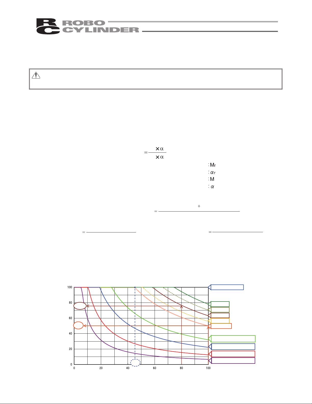
Warning: If an overload error occurs, extend the stopped time to lower the duty or decrease the
acceleration/deceleration speed.
[How to Calculate Duty]
Perform operation with the duty ratio at the allowable value or less.
Duty ratio is the operation rate, in time basis, of the actuator in 1 cycle that is indicated with “%” .
Figure out the load rate and acceleration/deceleration speed time ratio by calculation and read the duty ratio from
the graph.
When the load rate is less than 50%, an operation with 100% duty ratio should be available.
[2]
Acceleration/deceleration time ratio t
od
(%)
timeOperating
Acceleration time
during operation
Deceleration time
during operation
Acceleration/deceleration time ratio t
od
Acceleration (mm/s
2
) = Acceleration (G) × 9,800mm/s
2
Deceleration (mm/s
2
) = Deceleration (G) × 9,800mm/s
2
(sec.)
Acceleration time
Velocity at
operation (mm/s)
Acceleration during
operation
(mm/s2)
(sec.)
Deceleration time
Velocity at
operation
(mm/s)
Deceleration during
operation
(mm/s2)
(%)
Mr r
M
Load factor :LF
[1]
Load factor LF
It is descried in 2. Specifications regarding the maximum transportable weight at the rated acceleration and
rated acceleration/deceleration.
Acceleration/deceleration during operation
Transferring mass during operation
Rated acceleration/deceleration
Maximum transportable weight at the rated acceleration
(kg)
(G)
(kg)
(G)
Example) If the load factor LF is 80% and acceleration/deceleration time ratio todis 80%, the reference duty
is approx. 75%.
[3]
Read the duty ratio from the load rate LF and the acceleration speed time ratio t
od
that were used to figure
out the duty ratio.
LF = 100%
LF = 80%
LF = 60%
LF = Less than 50%
50%
75%
45%
LF = 125%
LF = 70%
LF = 90%
LF = 150%
LF = 200%
Acceleration/deceleration time ratio t (%)
Approx.
od
High Acceleration/Deceleration Type
High Acceleration/Deceleration Type
High Acceleration/Deceleration Type
Reference of Operation Duty (%)
LF = 330%
High Acceleration/Deceleration Type
9
Page 18
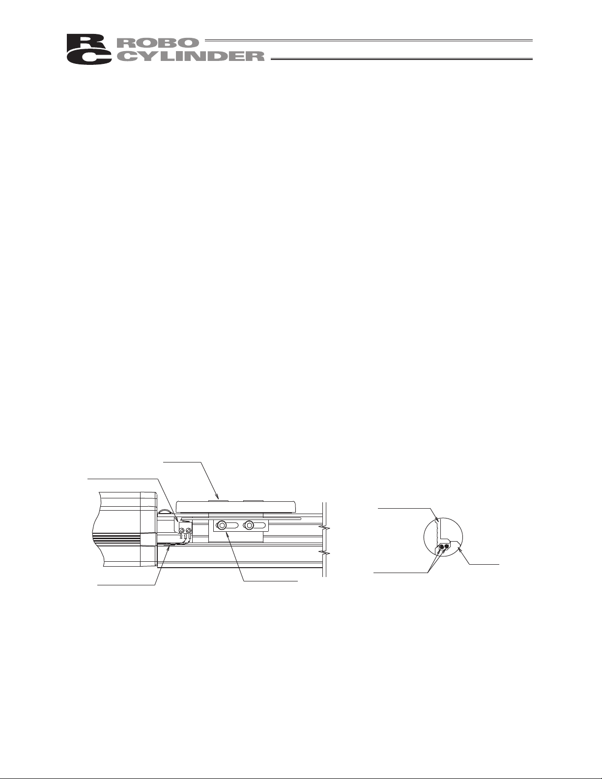
Switch cables
Slider
Microswitch
Switch dog
Switch cables
Side cover
Base
If the home is set on the opposite side, pay
attention to the stora
g
e of switch cables.
7. Do Not Loosen the Mounting Screws of Micro-Switches or Bend the Switch
Dogs.
On actuators with a switch (option), the switch is stored inside the actuator body. (The switch can be accessed
by removing the side covers.)
Microswitch and switch dog are adjusted to the optimal positions before shipment.
Do not loosen the mounting screws or bend the switch dog.
If the mounting screws are loosened or switch dog is bent, the optimal positions will be lost and the switch may
not demonstrate its intended function.
Do not increase the homing speed beyond the default factory setting.
If the homing speed is increased beyond the default, the switch may be damaged.
Do not move the slider toward the mechanical end from the home position other than during homing.
If the actuator is moved manually or at high speed by jogging, etc., and the switch dog contacts the microswitch
as a result, the switch may be damaged.
When moving the slider manually toward the mechanical end during motor replacement, etc., move the slider
slowly.
When changing the home direction after shipment (such as when a need arises to move the factory-set home
position to the opposite side due to a specification change, etc.), the microswitch position and switch dog must
be readjusted.
Should you require such adjustment, contact the IAI sales office near you.
If the side covers were removed for maintenance, etc., be careful not to pinch the switch cables when reinstalling
the covers.
In particular, pay attention when the home is set on the opposite side, because the switch cables are stored in
the space between a side cover and the base.
10
Page 19
8. Transporting and Handling
8.1 Handling the Actuator
8.1.1 Handling the Packed Unit
Unless otherwise specified, each actuator (axis) is shipped individually.
Please take care that the shipping box is not dropped or subjected to strong impact during transport.
The operator should not carry heavy shipping boxes by themselves.
If the shipping box is left standing, it should be in a horizontal position.
Do not climb on top of the shipping box.
Do not place heavy objects on top of the shipping box.
8.1.2 Handling the Actuator After It is Unpacked
Lift the actuator up by the base to remove it from the packing.
When carrying the actuator, take care not to bump it. Take particular care with the front cover and motor cover.
Do not exert excessive force on any part of the actuator.
Be careful not to cause the cables to receive a tensile force.
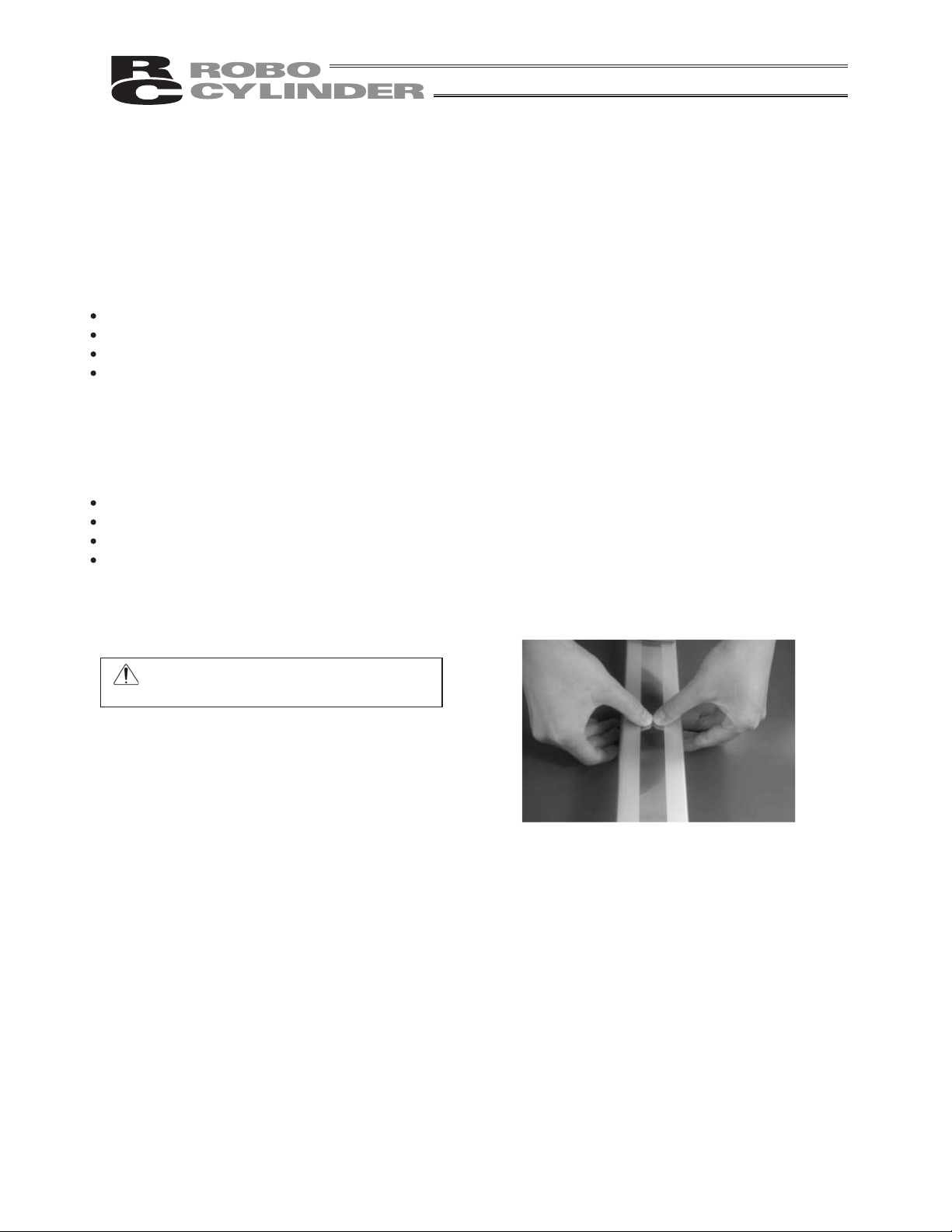
Note on handling the stainless sheet
The stainless sheet is designed very thin (thickness: Approx. 0.1 mm) in order to ensure flexibility. Therefore,
the stainless sheet is easily dented or scratched. Once dented or scratched, the stainless sheet may break
during use.
Warning: Do not press the sheet directly
with hands.
Supplement) Please refer to "Names of Parts" for the names of the actuator parts.
11
Page 20

8.2 Handling the Actuator Assembly
Pay attention to the following instructions when transporting an assembly of actuator axes.
8.2.1 Condition of Shipment from IAI (Assembled)
The actuators you have ordered are assembled at IAI, after which the assembly receives a shipping inspection
and is shipped in an outer frame with skids.
The assembly is packed with the sliders securely affixed so that they will not move unexpectedly during
transportation. In the case of a combined unit, the actuator ends are secured to prevent swinging due to external
vibration.
The package is not designed with special considerations for protection against impact due to dropping or
collision, so please handle the package with care. Also, do not place any heavy object on the outer frame,
as it is not strong enough to withstand loads.
When suspending the package using ropes, etc., pass the ropes from underneath the reinforcement frames
at the bottom of the skids. When lifting with a forklift, also place the forks underneath the skids.
Set down the package carefully so as not to apply impact to the assembly or cause it to bounce.
After unpacking, handle the actuator assembly correctly by observing the instructions given below.
8.2.2 Handling after Assembly with Peripheral Equipment
When transporting the actuators that have been assembled with peripheral equipment either at IAI or on your
site, observe the instructions given below.
Secure each slider to prevent unexpected movement during transportation.
If any actuator end is protruding, secure it to prevent swinging due to external vibration.
If the actuator ends are not secured, do not apply any impact force exceeding 0.3 G during transportation.
When suspending the actuator-assembled peripheral equipment using ropes, etc., make sure the ropes do
not contact the actuators directly.
Pass the ropes over appropriate cushion materials, and make sure the loads from the ropes will be
received by the base of each actuator.
Secure the end of the Y-axis using a separate rope to maintain the axis in a stable horizontal position. At
this time, be careful not to apply loads on the screw cover.
Be careful not to allow the brackets, covers and connector box of each actuator to receive loads. Also
protect the cables from pinching or excessive deformation.
12
Page 21

International Standards Compliances
This actuator complies with the following overseas standard.
Refer to Overseas Standard Compliance Manual (ME0287) for more detailed information.
RoHS Directive CE Marking
Optional
13
Page 22
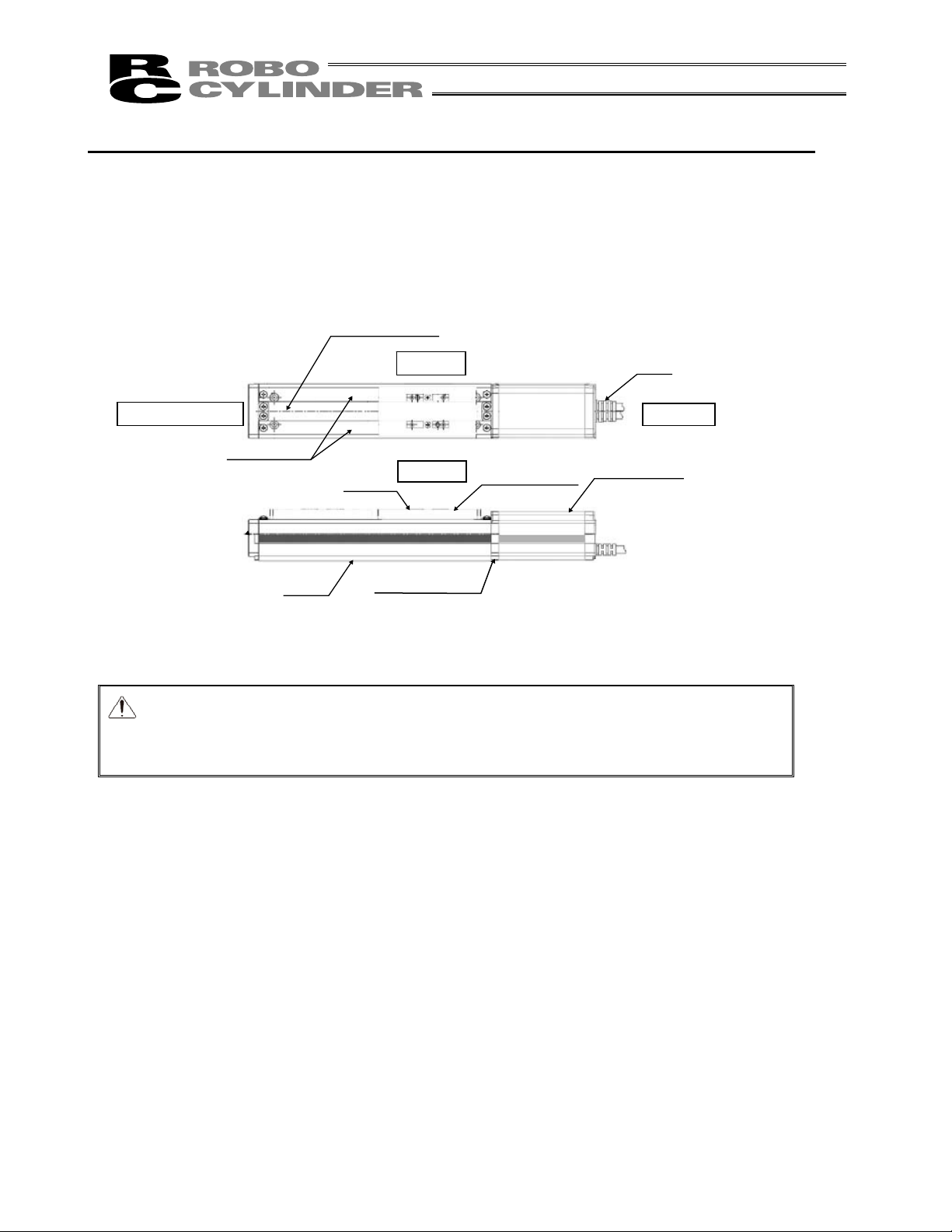
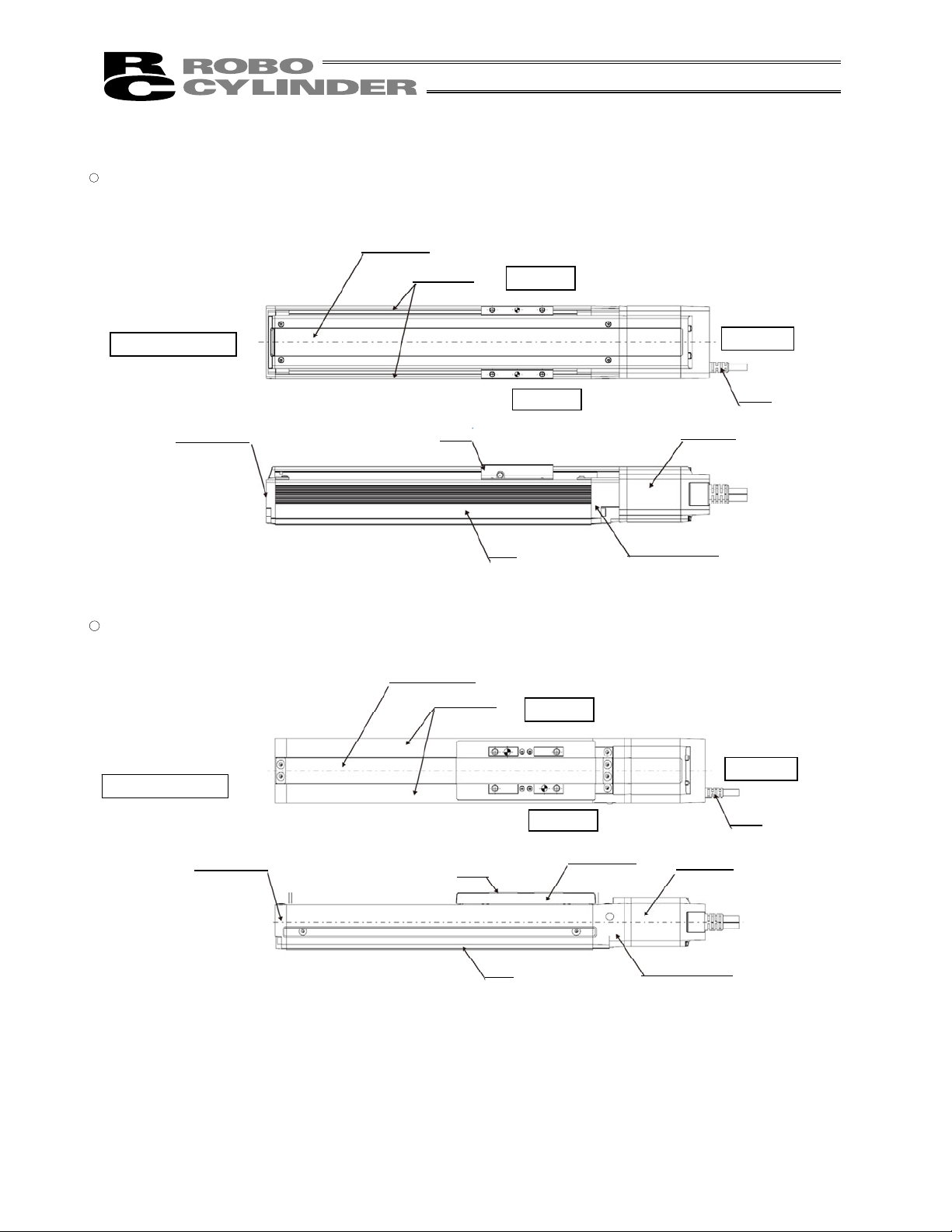
Bearing Housing
Stainless Sheet
Side Cover
Right Side
Opposite Motor End
Motor End
Base
Motor Cover
Slider
Left Side
Front Cover
Cable
Slider Cover
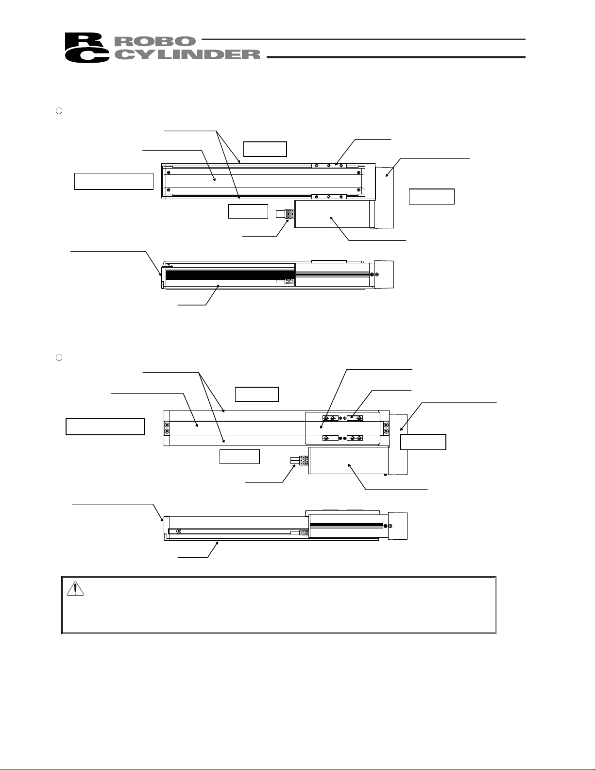
Names of the Parts
The names of the actuator parts are indicated below.
The left and right sides are indicated by looking at the actuator from the motor end with the actuator set down
horizontally. Front end means the side opposite the motor end.
1. Motor Straight Type (Standard) RCS2
Caution: The cable directly connected to the actuator is not robot cable even when ordered
with robot cable option. When designing, please be sure not to give repeated
bending loads to this cable.
The robot cable is applicable only to the connecting cables.
14
Page 23

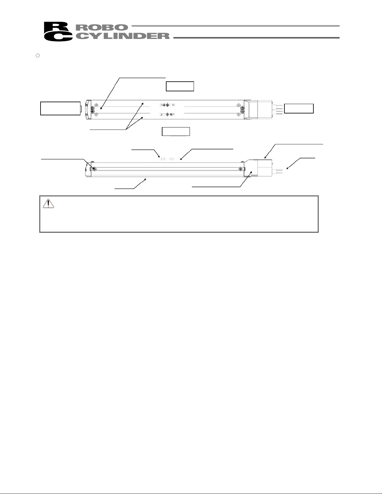
� Coupling Type (SA7C, SS7C, SS8C)
Caution: The cable directly connected to the actuator is not robot cable even when ordered
with robot cable option. When designing, please be sure not to give repeated
bending loads to this cable.
The robot cable is applicable only to the connecting cables.
Stainless Sheet
Side Cover
Right Side
Opposite Motor End
Motor End
Base
Encoder Cover
Slider
Left Side
Front Cover
Motor Housing
Cable
Slider Cover
15
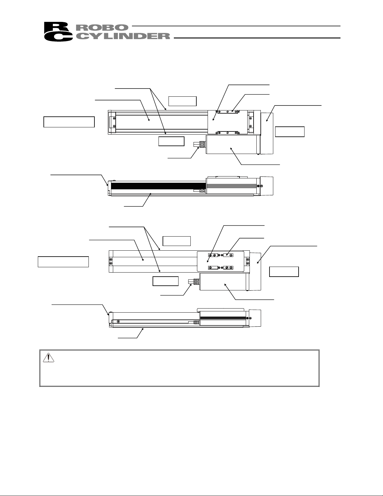
Page 24
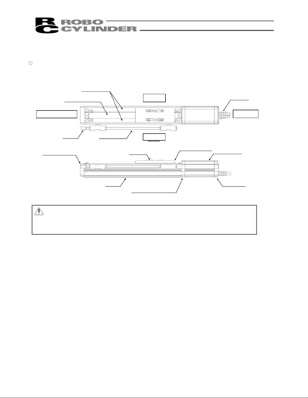
Stainless Sheet
Side Cover
Right Side
Opposite Motor
End
Motor End
Base
Encoder Cover
Slider
Left Side
Front Cover
Motor Housing
Cable
Slider Cover
�
Built-in Type (SA4D, SA5D, SA6D)
Caution: The cable directly connected to the actuator is not robot cable even when ordered
with robot cable option. When designing, please be sure not to give repeated
bending loads to this cable.
The robot cable is applicable only to the connecting cables.
16
Page 25
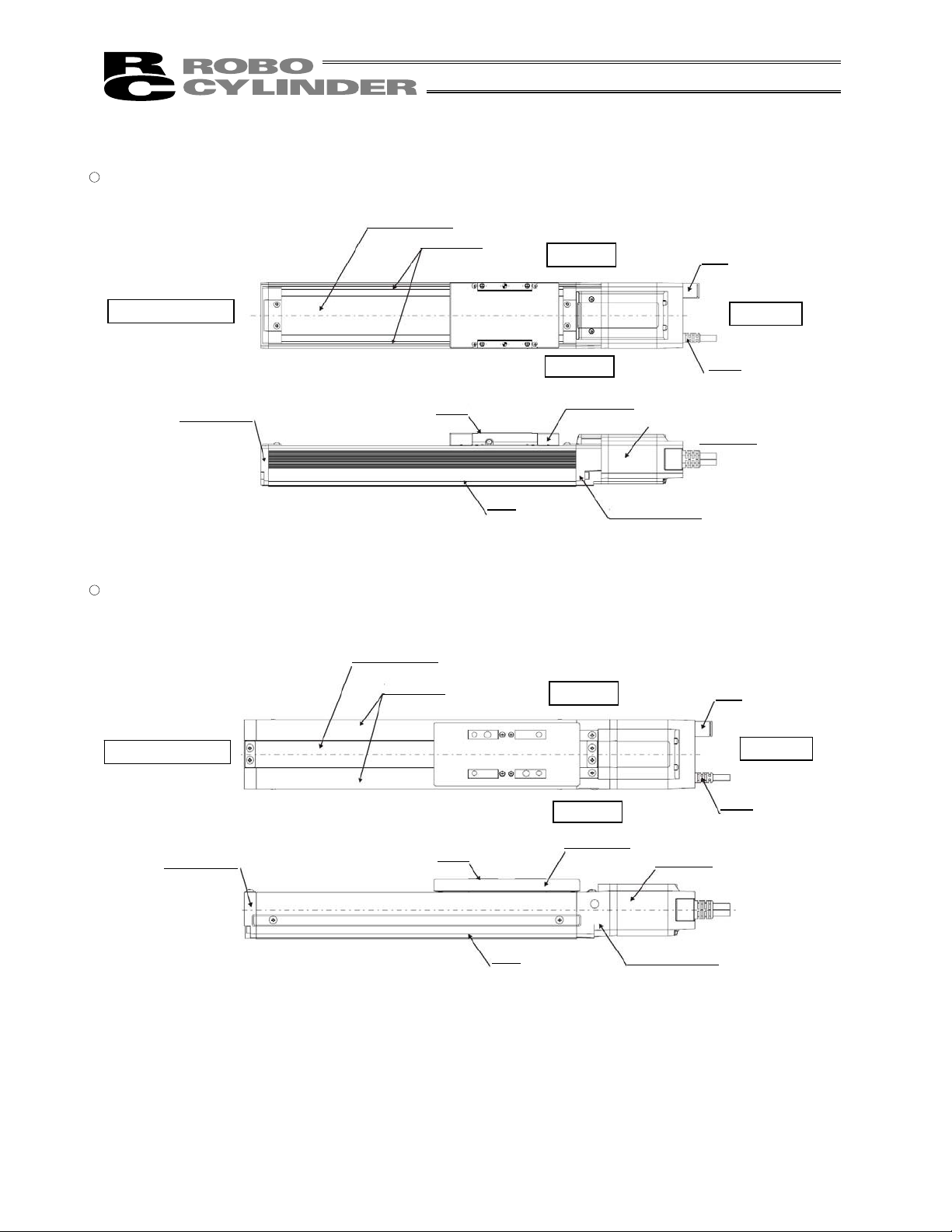
2. Motor Straight Type (Standard) RCS3(P)
�
Coupling Type (SA8)
� Coupling Type (SS8)
Stainless Sheet
Right Side
Opposite Motor End
Motor End
Left Side
Side Cover
Base
Bearing Housing
Slider
Motor Unit
Cable
Slider Cover
Front bracket
Side Cover
Right Side
Opposite Motor End
Motor End
Base
Left Side
Cable
Bearing Housing
Slider
Motor unit
Front bracket
Screw cover
17
Page 26
Stainless Sheet
Side Cover
Right Side
Opposite Motor End
Motor End
Base
Motor Cover
Slider
Left Side
Front Cover
Bearing Housing
Cable
Plug
Vacuum Tube
Slider Cover
Rear Cover
3. Motor Straight Type (Cleanroom Specification) RCS2-CR
� Coupling Type (SA4C, SA5C, SA6C, SA7C, SS7C, SS8C), Built-in Type (SA5D, SA6D)
Caution: The cable directly connected to the actuator is not robot cable even when ordered
with robot cable option. When designing, please be sure not to give repeated
bending loads to this cable.
The robot cable is applicable only to the connecting cables.
18
Page 27
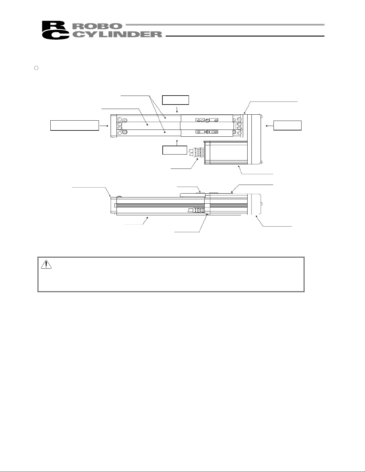
Stainless Sheet
Right Side
Opposite Motor End
Motor End
Base
Left Side
Slider
Stainless Sheet
Right Side
Opposite Motor End
Motor End
Left Side
Base
Slider
Slider cover
Slider Cover
4. Motor Straight Type (Cleanroom specification) RCS3(P)-CR
� Coupling Type (SA8)
� Coupling Type (SS8)
Side Cover
Cable
Bearing Housing
Motor Unit
Side Cover
Bearing Housing
Motor Unit
Cable
Joint
Joint
Front bracket
Front bracket
19
Page 28
Stainless Sheet
Side Cover
Right Side
Opposite Motor End
Motor End
Base
Motor Cover
Slider
Left Side
Front Cover
Bearing Housing
Cable
Pulley Cover
Slider Cover
Rear Cover
5. Motor Reversing Type RCS2
� SA4R, SA5R, SA6R, SA7R, SS7R, SS8R
Caution: The cable directly connected to the actuator is not robot cable even when ordered
with robot cable option. When designing, please be sure not to give repeated
bending loads to this cable.
The robot cable is applicable only to the connecting cables.
20
Page 29
Stainless Sheet
Side Cover
Right Side
Opposite Motor End
Motor End
Left Side
Cable
Base
Slider
Stainless Sheet
Side Cover
Slider
Slider Cover
Right Side
Opposite Motor End
Motor End
Left Side
Cable
Base
Reversing Bracket
Reversing Bracket
Motor Unit
6. Motor Reversing Type (Standard) RCS3 (P)
� SA8R
� SS8R
Caution: The cable directly connected to the actuator is not robot cable even when ordered
with robot cable option. When designing, please be sure not to give repeated
bending loads to this cable.
The robot cable is applicable only to the connecting cables.
Front Bracket
Motor Unit
Front Bracket
21
Page 30
Stainless Sheet
Side Cover
Right Side
Opposite Motor End
Motor End
Left Side
Cable
Slider
Slider Cover
Base
Stainless Sheet
Side Cover
Right Side
Opposite Motor End
Motor End
Left Side
Cable
Slider Cover
Base
Slider
Slider
Reversing Bracket
Reversing Bracket
7. Motor Reversing Type (Slider Roller Specification) RCS3 (P)
� SA8R (Option model number: SR)
� SS8R (Option model number: SR)
Caution: The cable directly connected to the actuator is not robot cable even when ordered
with robot cable option. When designing, please be sure not to give repeated
bending loads to this cable.
The robot cable is applicable only to the connecting cables.
Motor Unit
Front bracket
Motor Unit
Front Bracket
22
Page 31

1. Checking the Product
If based on a standard configuration, this product consists of the items listed below.
Caution: Ch eck the packed items against the packing specification. Should you find a wrong model number
or any missing item, please contact your IAI dealer or IAI.
1.1 Components
skrameRledoMemaN.oN
1 Actuator
Refer to “How to Read the Model Nameplate”
and “How to Read the Model Number.”
seirosseccA
1*elbacredocnerotoM2
slaesgnikamemoH3
ediuGpetSkciuQ4
launaMnoitarepO
5
ediuGytefaS6
*1 The motor cable and encoder cable supplied with each actuator vary depending on the controller used with
the actuator. [Refer to 10, “Motor/Encoder Cables.”]
1.2 Operation Manuals for Controllers Supported by This Product
(1) XSEL-J/K controllers
.oNlortnoCemaN.oN
6110EMrellortnoCK/J-LESXroflaunaMnoitarepO1
2 Operation Manual for PC Software IA-101-X-MW/IA-101-X-USBMW ME0154
3810EMGT/DT/T-LEStnadnePgnihcaeTroflaunaMnoitarepO3
0610EMDX/X-T-AItnadnePgnihcaeTroflaunaMnoitarepO4
4210EMteNeciveDroflaunaMnoitarepO5
3210EMkniL-CCroflaunaMnoitarepO6
3510EMSUBIFORProflaunaMnoitarepO7
0410EMtenrehtELES-XroflaunaMnoitarepO8
8310EMdraoBO/Itniop-itluMroflaunaMnoitarepO9
10 Operation Manual for Dedicated Multi-point I/O Board Terminal Block ME0139
(CD/DVD)
1. Checking the Product
23
Page 32

(2) XSEL-P/Q controllers
No. Name Control No.
1 Operation Manual for XSEL-P/Q Controller ME0148
2 Operation Manual for XSEL-P/Q/PX/QX RC Gateway Function ME0188
3 Operation Manual for PC Software IA-101-X-MW/IA-101-X-USBMW ME0154
4 Operation Manual for Teaching Pendant SEL-T/TD/TG ME0183
5 Operation Manual for Teaching Pendant IA-T-X/XD ME0160
6 Operation Manual for DeviceNet ME0124
7 Operation Manual for CC-Link ME0123
8 Operation Manual for PROFIBUS ME0153
(3) SSEL controllers
No. Name Control No.
1 Operation Manual for SSEL Controller ME0157
2 Operation Manual for PC Software IA-101-X-MW/IA-101-X-USBMW ME0154
3 Operation Manual for Teaching Pendant SEL-T/TD/TG ME0183
4 Operation Manual for Teaching Pendant IA-T-X/XD ME0160
5 Operation Manual for DeviceNet ME0124
6 Operation Manual for CC-Link ME0123
7 Operation Manual for PROFIBUS ME0153
1. SampleChecking the Product
24
Page 33

(4) SCON controllers
No. Name Control No.
1 Operation Manual for SCON Controller ME0161
2 Operation Manual for PC Software RCM-101-MW/RCM-101-USB ME0155
3 Operation Manual for Teaching Pendant CON-T/TG ME0178
4 Operation Manual for Touch Panel Teaching Pendant CON-PT/PD/PG ME0227
5 Operation Manual for Simple Teaching Pendant RCM-E ME0174
6 Operation Manual for Data Setter RCM-P ME0175
7 Operation Manual for Touch Panel Display RCM-PM-01 ME0182
8 Operation Manual for DeviceNet ME0124
9 Operation Manual for CC-Link ME0123
10 Operation Manual for PROFIBUS ME0153
1.3 How to Read the Model Nameplate
Model
Serial numbe
r
1. Checking the Product
25
Page 34

1. SampleChecking the Product
CE: CE Marking
26
Page 35

CE: CE Marking
1. Checking the Product
27
Page 36

2. Specification
(1) Maximum speed
The maximum speed of the actuator is limited to prevent resonance of the ball screw shaft and also in
consideration of the restrictions on motor speed.
Observe the maximum speed limits specified below.
[Cleanroom specification RCS2CR]
Strokes and maximum speed limits (unit: mm/sec)
Caution: Do not set any speed or acceleration/deceleration exceeding the rated speed or
acceleration/deceleration. Doing so may result in vibration, failure or shorter life.
When combining multiple axes and synchronizing their operations, the speed and
acceleration/deceleration to be set should correspond to the highest speed and
largest acceleration/deceleration among those of the combined axes.
In particular, exercise caution because setting an acceleration/deceleration
exceeding the rated acceleration/deceleration may cause the actuator to suffer
creep or the coupling to slip.
50 100 150 200 250 300 350 400 450 500 550 600 700 800 900 1000
SA4
5615.2
0335
56601
SA5
0910023
0830046
06700821
20
1300
800
SA6
5310610910023
0720230830046
045046067008
20
09906110031
800
SA7
0210610024
0420230048
08404600861
SS7
0036
00612
SS8
56201308308400501
515526567069000102
Stroke [mm]
Type
Lead
[mm]
(installed horizontally)
(installed vertically)
(installed horizontally)
(installed vertically)
230
470
12
2. Specication
28
Page 37

50 100 150 200 250 300 350 400 450 500 550 600 650 700 750 800 850 900 950 1000 1050 1100
SA8
100
5 300 260 230 200 180 170 150 135 120 110
10 600 530 470 410 370 340 310 270 250 230
20 1200 1070 940 840 750 670 610 550 500 460
30 1800 1610 1420 1260 1120 1010 910 830 760 690
150
10 600 530 470 410 370 340 310 270 250 230
20 1200 1070 940 840 750 670 610 550 500 460
30 1800 1610 1420 1260 1120 1010 910 830 760 690
SS8
100
5 300 275 240 215 190 170 150 140 125 � �
10 600 550 485 430 385 345 310 280 255 �
�
20 1200 1105 970 860 770 690 625 565 515 � �
30 1800 1660 1460 1295 1155 1035 935 850 775 � �
150
10 600 550 485 430 385 345 310 280 255 � �
20 1200 1105 970 860 770 690 625 565 515 � �
30 1800 1660 1460 1295 1155 1035 935 850 775 � �
50 100 150 200 250 300 350 400 450 500 550 600 650 700 750 800 850 900 950 1000 1050 1100
SA8
100
5 300 250 220 190 170 160 140 130 120 110
10 600 500 440 390 350 320 290 260 240 220
20 1200 1010 890 790 710 640 580 530 480 440
30 1800 1510 1340 1190 1070 960 870 790 720 660
150
10 600 500 440 390 350 320 290 260 240 220
20 1200 1010 890 790 710 640 580 530 480 440
30 1800 1510 1340 1190 1070 960 870 790 720 660
SS8
100
5 300 275 240 215 190 170 150 140 125 � �
10 600 550 485 430 385 345 310 280 255 � �
20 1200 1105 970 860 770 690 625 565 515 � �
30 1800 1660 1460 1295 1155 1035 935 850 775 � �
150
10 600 550 485 430 385 345 310 280 255 � �
20 1200 1105 970 860 770 690 625 565 515 � �
30 1800 1660 1460 1295 1155 1035 935 850 775 � �
[RCS3 (P)]
Strokes and maximum speed limits [unit: mm/s]
[RCS3 (P) CR Cleanroom Specification @@nuke@@
Strokes and maximum speed limits [unit: mm/s]
Type
Lead
[mm]
Motor
capacity
[W]
Type
Lead
[mm]
Motor
capacity
[W]
2. Specication
29
Page 38

(2) Maximum acceleration and loading capacity
[RCS2]
Type
Motor capacity
[W]
Lead
[mm]
Maximum acceleration [G]
Maximum loading
capacity [kg]
Horizontal 8
2.5
Vertical
0.2
High-acceleration/deceleration mode: 0.2
4.5
Horizontal 6
5
Vertical
0.3
High-acceleration/deceleration mode: 1.0
2.5
Horizontal 4
SA4C 20
10
Vertical
0.3
High-acceleration/deceleration mode: 1.0
1
Horizontal 12
3
Vertical
0.2
High-acceleration/deceleration mode: 0.2
4
Horizontal 8
6
Vertical
0.3
High-acceleration/deceleration mode: 0.8
2
Horizontal 4
SA5C 20
12
Vertical
0.3
High-acceleration/deceleration mode: 0.8
1
Horizontal 18
3
Vertical
0.2
High-acceleration/deceleration mode: 0.2
6
Horizontal 12
6
Vertical
0.3
High-acceleration/deceleration mode: 1.0
3
Horizontal 6
SA6C 30
12
Vertical
0.3
High-acceleration/deceleration mode: 1.0
1.5
Horizontal 40
4
Vertical
0.2
High-acceleration/deceleration mode: 0.2
12
Horizontal 25
8
Vertical
0.3
High-acceleration/deceleration mode: 1.0
6
Horizontal 12
SA7C 60
16
Vertical
0.3
High-acceleration/deceleration mode: 1.0
3
Horizontal 30
6
Vertical
0.3
8
Horizontal 15
SS7C 60
12
Vertical
0.3
4
Horizontal 40
10
Vertical
0.3
8
Horizontal 20
100
20
Vertical
0.3
4
Horizontal 60
10
Vertical
0.3
12
Horizontal 30
SS8C
150
20
Vertical
0.3
6
2. Specication
30
Page 39

Type
Motor capacity
[W]
Lead
[mm]
Maximum acceleration [G]
Maximum loading
capacity [kg]
Horizontal 8
2.5
Vertical
0.2
4.5
Horizontal 6
5
Vertical
0.3
2.5
Horizontal 4
SA4D 20
10
Vertical
0.3
1
Horizontal 12
3
Vertical
0.2
4
Horizontal 8
6
Vertical
0.3
2
Horizontal 4
SA5D 20
12
Vertical
0.3
1
Horizontal 18
3
Vertical
0.2
6
Horizontal 12
6
Vertical
0.3
3
Horizontal 6
SA6D 30
12
Vertical
0.3
1.5
Horizontal 8
2.5
Vertical
0.2
4.5
Horizontal 6
5
Vertical
0.3
2.5
Horizontal 4
SA4R 20
10
Vertical
0.3
1
Horizontal 12
3
Vertical
0.2
4
Horizontal 8
6
Vertical
0.3
2
Horizontal 4
SA5R 20
12
Vertical
0.3
1
Horizontal 18
3
Vertical
0.2
6
Horizontal 12
6
Vertical
0.3
3
Horizontal 6
SA6R 30
12
Vertical
0.3
1.5
Horizontal 40
4
Vertical
0.2
12
Horizontal 26
8
Vertical
0.3
6
Horizontal 12
SA7R 60
16
Vertical
0.3
3
2. Specication
31
Page 40

Type
Motor capacity
[W]
Lead
[mm]
Maximum acceleration [G]
Maximum loading
capacity [kg]
Horizontal 30
6
Vertical
0.3
8
Horizontal 15
SS7R 60
12
Vertical
0.3
4
Horizontal 40
10
Vertical
0.3
8
Horizontal 20
100
20
Vertical
0.3
4
Horizontal 60
10
Vertical
0.3
12
Horizontal 30
SS8R
150
20
Vertical
0.3
6
2. Specication
32
Page 41

[Cleanroom specification RCS2CR]
Type
Motor capacity
[W]
Lead
[mm]
Maximum acceleration [G]
Maximum loading
capacity [kg]
Horizontal 8
2.5
Vertical
0.2
4.5
Horizontal 6
5
Vertical
0.3
2.5
Horizontal 4
SA4C 20
10
Vertical
0.3
1
Horizontal 12
3
Vertical
0.2
4
Horizontal 8
6
Vertical
0.3
2
Horizontal 4
SA5C 20
12
Vertical
0.3
1
Horizontal 18
3
Vertical
0.2
6
Horizontal 12
6
Vertical
0.3
3
Horizontal 6
SA6C 30
12
Vertical
0.3
1.5
Horizontal 40
4
Vertical
0.2
12
Horizontal 25
8
Vertical
0.3
6
Horizontal 12
SA7C 60
16
Vertical
0.3
3
Horizontal 30
6
Vertical
0.3
8
Horizontal 15
SS7C 60
12
Vertical
0.3
4
Horizontal 40
10
Vertical
0.3
8
Horizontal 20
100
20
Vertical
0.3
4
Horizontal 60
10
Vertical
0.3
12
Horizontal 30
SS8C
150
20
Vertical
0.3
6
2. Specication
33
Page 42

Type
Motor capacity
[W]
Lead
[mm]
Maximum acceleration [G]
Maximum loading
capacity [kg]
Horizontal 12
3
Vertical
0.2
4
Horizontal 8
6
Vertical
0.3
2
Horizontal 4
SA5D 20
12
Vertical
0.3
1
Horizontal 18
3
Vertical
0.2
6
Horizontal 12
6
Vertical
0.3
3
Horizontal 6
SA6D 30
12
Vertical
0.3
1.5
2. Specication
34
Page 43

[RCS3(P) Cleanroom specification RCS3(P)CR]
Loading capacity by acceleration [kg]
Type
Motor capacity
[W]
Lead
[mm]
Installation
position
Rated
acceleration
[G]
0.2G 0.3G 0.5G 0.7G 1.0G
Horizontal 0.2 80 65 - - -
5
Vertical 0.2 16 12 - - -
Horizontal 0.3 40 40 20 - -
10
Vertical 0.2 8 8 4 - -
Horizontal 0.3 20 20 10 5 -
20
Vertical 0.2 4 4 2 1.5 -
Horizontal 0.3 8 8 6 4 1
100
30
Vertical 0.2 2 2 1.5 1 -
Horizontal 0.3 60 60 30 - -
10
Vertical 0.2 12 12 6 - -
Horizontal 0.3 30 30 15 7.5 -
20
Vertical 0.2 6 6 3 2 -
Horizontal 0.3 12 12 10 6 2
SA8
150
30
Vertical 0.2 3 3 2 1.5 -
Horizontal 0.2 80 65 - - -
5
Vertical 0.2 16 12 - - -
Horizontal 0.3 40 40 20 - -
10
Vertical 0.2 8 8 4 - -
Horizontal 0.3 20 20 10 5 -
20
Vertical 0.2 4 4 2 1.5 -
Horizontal 0.3 8 8 6 4 1
100
30
Vertical 0.2 2 2 1.5 1 -
Horizontal 0.3 60 60 30 - -
10
Vertical 0.2 12 12 6 - -
Horizontal 0.3 30 30 15 7.5 -
20
Vertical 0.2 6 6 3 2 -
Horizontal 0.3 12 12 10 6 2
SS8
150
30
Vertical 0.2 3 3 2 1.5 -
Caution: 1. The figures of loading capacity by acceleration other than those at the rated acceleration of 0.3
G are reference values and not guaranteed. Use these values only as a reference.
2. Even when the acceleration is less than the rated acceleration, the loading capacity will not
exceed the loading capacity at the rated acceleration.
2. Specication
35
Page 44

(3) Rated Thrust
[RCS2 Cleanroom specification RCS2CR]
Type Motor capacity [W] Lead [mm]
Rated thrust [N]
2.5 78.4
5 39.2
SA4 20
10 19.6
3 65.7
6 33.3
SA5
12 16.7
RCS2-SA5C
20
20 10.7
3 96.8
6 48.4
SA6
12 24.2
RCS2-SA6C
30
20 15.8
4 255.0
8 127.5
SA7
60
16 63.8
6 170.0
SS7 60
12 85.0
10 169.0
100
20 84.9
10 256.0
SS8
150
20 128.0
2. Specication
36
Page 45

[RCS3/RCS3P Cleanroom specification RCS3CR/RCS3PCR]
Type Motor capacity [W] Lead [mm]
Rated thrust [N]
5 339.7
10 169.8
20 84.9
100
30 56.6
10 255.3
20 127.6
SA8
150
30 85.1
5 339.7
10 169.8
20 84.9
100
30 56.6
10 255.3
20 127.6
SS8
150
30 85.1
2. Specication
37
Page 46

(4) Driving method
[RCS2 Cleanroom specification RCS2CR]
Type
Motor capacity
[W]
Lead Encoder pulses
*1
Driving method
2.5
5
SA4 20
10
Ball screw
�8 mm
Rolled, C10
3
6
SA5
12
RCS2-SA5C
20
20
Ball screw
�10 mm
Rolled, C10
3
6
SA6
12
RCS2-SA5C
30
20
Ball screw
�10 mm
Rolled, C10
4
8
SA7 60
16
Ball screw
�12 mm
Rolled, C10
6
SS7 60
12
Ball screw
�10 mm
Rolled, C10
10
100
20
10
SS8
150
20
16384
Ball screw
�16 mm
Rolled, C10
*1. Number of pulses input to the controller.
[RCS3 (P) Cleanroom specification RCS3 (P) CR]
Type
Motor capacity
[W]
Lead Encoder pulses*1 Driving method
5
10
20
100
30
Ball screw
�16 mm
Rolled, C10
[Rolled, C5 or
equivalent]
10
20
SA8
150
30
Ball screw
�16 mm
Rolled, C10
[Rolled, C5 or
equivalent]
5
10
20
100
30
Ball screw
�16 mm
Rolled, C10
[Rolled, C5 or
equivalent]
10
20
SS8
150
30
16384
Ball screw
�16 mm
Rolled, C10
[Rolled, C5 or
equivalent]
*1. Number of pulses input to the controller.
2. Specication
38
Page 47

(5) Cleanliness class of clean room type RCP2CR
Item Specification
Cleanliness
class
Class 10 (1 m) when air is suctioned from the suction joint at an appropriate rate of
suction
(6) Common specifications
[RCS2, Cleanroom specification RCS2CR]
Item Specification
Positioning repeatability
0.02 mm
Lost motion 0.1 mm or less
[RCS3(P), Cleanroom specification RCS3(P)CR]
Item Specification
Positioning repeatability
0.02 mm [0.01 mm]
Lost motion 0.1 mm or less [0.05 mm or less]
The values in [ ] apply to the high-precision type.
2. Specication
39
Page 48

(7) Load on the Actuator
Do not exceed the load shown in the load specification column. Please make note of the slider moment,
allowable overhang length and the load weight.
[RCS2, Cleanroom specification RCS2CR]
Dynamic allowable load moments
Model Ma Mb Mc
SA4
2.7 N�m (0.27 kgf�m) 3.9 N�m (0.4 kgf�m) 6.8 N�m (0.7 kgf�m)
SA5
4.9 N�m (0.5 kgf�m) 6.8 N�m (0.7 kgf�m) 11.7 N�m (1.2 kgf�m)
SA6
8.9 N�m (0.9 kgf�m) 12.7 N�m (1.3 kgf�m) 18.6 N�m (1.9 kgf�m)
SA7
13.9 N�m (1.41 kgf�m) 19.9 N�m (2 kgf�m) 38.3 N�m (3.9 kgf�m)
SS7
14.7 N�m (1.49 kgf�m) 14.7 N�m (1.49 kgf�m) 33.3 N�m (3.39 kgf�m)
SS8
36.3 N�m (3.7 kgf�m) 36.3 N�m (3.7 kgf�m) 77.4 N�m (7.89 kgf�m)
Allowable overhang lengths
Model Ma direction Mb direction Mc direction
SA4 120 mm or less 120 mm or less 120 mm or less
SA5 150 mm or less 150 mm or less 150 mm or less
SA6 220 mm or less 220 mm or less 220 mm or less
SA7 230 mm or less 230 mm or less 230 mm or less
SS7 300 mm or less 300 mm or less 300 mm or less
SS8 450 mm or less 450 mm or less 450 mm or less
[RCS3(P), Cleanroom specification RCS3 (P) CR]
Dynamic allowable load moments
Model Motor capacity [W] Ma Mb Mc
100
23.1 N�m (2.35 kgf�m) 32.9 N�m (3.35 kgf�m) 54.1 N�m (5.52 kgf�m)
SA8
150
23.1 N�m (2.35 kgf�m) 32.9 N�m (3.35 kgf�m) 54.1 N�m (5.52 kgf�m)
100
36.3 N�m (3.7 kgf�m) 36.3 N�m (3.7 kgf�m) 77.4 N�m (7.9 kgf�m)
SS8
150
36.3 N�m (3.7 kgf�m) 36.3 N�m (3.7 kgf�m) 77.4 N�m (7.9 kgf�m)
Allowable overhang lengths
Model Motor capacity [W] Ma direction Mb direction Mc direction
100 390 mm 390 mm 390 mm
SA8
150 390 mm 390 mm 390 mm
100 450 mm 450 mm 450 mm
SS8
150 450 mm 450 mm 450 mm
2. Specication
40
Page 49

Mb, Mc directions
Ma direction
Directions of moment forces
Directions of allowable overhangs
L
Reference position
RCS2
RCS2CR
SA4SS4 31.2mm
SA5SS5 39.0mm
SA6SS6 40.0mm
SA7 43.0mm
SS7 36.0mm
SS8 48.0mm
RCS3P
RCS3PCR
SA8 44.0mm
SS8 48.0mm
Y-axis
X-axis
The Ma and Mc moments applying
on this slider should be kept to onehalf the allowable moment.
� The allowable overhang lengths are based on a configuration where the center of gravity of the load mounted
on the actuator corresponds to the center of the overhang length.
(Note) To calculate the moments in Ma and Mc directions, offset the reference position by L mm from the top
surface of the slider, as shown in the figure below.
If an actuator is used as the Y-axis in a cantilever system based on X-Y combination, its base deforms easily.
Accordingly, keep the Ma and Mc moments to no more than one-half their respective ratings. (See the figure
below.)
Caution: Allowing the slider to receive an excessive load moment will shorten the service
life of the guides. If the allowable overhang length is exceeded, vibration may
generate or the service life of the guides may be reduced.
41
2. Specication
Page 50

(7) Actuator Precision
[1] Actuator installation surface
Parallelism of the actuator installation surface (bottom surface of the base) and load installation surface
(top surface) at an arbitrary stroke position: 0.1 mm or less
[2] Traveling parallelism when the actuator is installed (affixed on a flat, smooth surface
*1
): 0.05 mm/m or
less
Condition: The above values have been measured at 20�C. *1 Parallelism: 0.05 mm/m or less
2. Specication
42
Page 51

3. Life
One factor that affects the traveling life of an actuator is “Rated Load.”
There are two types of rated loads: “Static Rated Load” and “Dynamic Rated Load.”
� “Static Rated Load”: Load applied while the actuator is stopped, as a result of which minor pressure marks
are left on the contact surface
� “Dynamic Rated Load”: Load under which the actuator can travel for a specified distance and still meet a
specified probability of survival defined by no damage to its guide.
Manufacturers of guides indicate the life of each guide by a dynamic rated load based on a probability of survival
(no damage to the guide) of 90% after 50 km of traveling.
With industrial equipment, however, dynamic rated loads must be defined based on longer traveling distance of
5,000 km to 10,000 km given the moving speed, operating ratios and other operating conditions of these
equipment.
Also note that guides are generally designed with a sufficient life against radial loads. Moment loads that are
applied at positions away from the guide center are most damaging to guides.
The traveling life is calculated by assuming that the actuator travels 5,000 km or 10,000 km while receiving the
allowable load moment, based on a load coefficient of 1.2.
[For the allowable dynamic load moment, refer to 2, “Specifications.”]
� Models with traveling life of 5,000 km
RCS2- SA4C, SA5C, SA6C, SA7C, SA4D, SA5D, SA6D, SA4R, SA5R, SA6R, SA7
RRCS2CR- SA4C, SA5C, SA6C, SA7C, SA5D, SA6D
� Models with traveling life of 10,000 km
RCS2- SS7C, SS8C, SS7R, SS8R
RCS2CR- SS7C, SS8C
RCS3/RCS3P- SA8C, SS8C, SA8R, SS8R
RCS3CR/RCS3PCR- SA8C, SS8C
The formula for calculating the allowable dynamic load moment corresponding to a traveling life of 5,000 km is
shown below. If the traveling life is 10,000 km, replace “5000 km” in the formula with “10000 km”:
The life at the actual moment applied is calculated by the formula below:
CIA : Allowable dynamic load moment
fw : Load coefficient (= 1.2)
M
50
: Dynamic rated moment based on 50 km of traveling and
probability of survival of 50%
L : Traveling life (probability of survival: 90%)
C
IA
: Allowable dynamic moment
P : Actual moment applied
3. Life
43
Page 52

4. Installation and Storage/Preservation Environment
4.1 Installation Environment
The actuator should be set up in an environment, which meets the following criteria:
Avoid direct sunlight.
Avoid radiant heat from strong heat sources such as a furnace.
Surrounding air temperature should be 0 ~ 40C.
The humidity should be less than 85% and there should be no condensation.
Avoid exposure to corrosive or combustible gases.
The area should have very little dust and be suitable for normal assembly operations.
Avoid exposure to oil mist or fluids used in cutting.
The unit should not be subject to impacts or vibrations.
Avoid extreme electromagnetic waves, ultraviolet rays and radiation.
This product is not intended to be used in a chemical environment.
In general, the environment should be one in which an operator can work without protective gear.
Work space needed for maintenance/inspection
[Motor straight type] [Motor reversing type]
4.2 Storage/Preservation Environment
The storage/preservation environment should be similar to the installation environment. In addition, you must
take precautions against condensation if the unit is to be stored for a long period of time. Unless there are
special instructions, we do not include moisture absorption agents when shipping the unit. If you are storing the
unit where condensation might occur, then you must treat the entire package or treat the unit itself after it is
unpacked to prevent condensation. The unit can withstand up to 60C during a short storage/preservation
interval but only up to 50C if the storage/preservation period is longer than one month.
4.Installation and Storage/Preservation Environment
44
Page 53

5. Installation
The method to install your actuator in a mechanical system is explained.
5.1 Installation
Install the actuator as explained below, as a rule.
Pay attention to these items when installing the actuator (except for custom-order models).
: Installable : Daily inspection is required x: Not installable
Type
SA4
SA5
SA6
SA7, SS7
SS8
SA8 (with stainless steel sheet)
SA8 (with screw cover)
Installation postures
Horizontal
installation
Vertical
installation
Sideway
installation
Ceiling mount
installation
5. Installation
Horizontal Vertical Sideway
Ceiling mount
45
Page 54

5. Installation
Caution: 1.
2. The clean room types listed below cannot be guaranteed to meet Cleanliness Class 10 if
they are installed in the vertical orientation, the horizontally wall mounted orientation or in the
ceiling mounted orientation since they do not possess a structure to grip the stainless steel
sheet from the side cover.
Please contact us if it is necessary to install the following models in an orientation other than
the horizontal orientation.
3. The actuator with the stainless sheet can be installed sideways or ceiling mount, but it must
4. There is a concern that the screw cover may get warped and interfere with a work piece for
When the unit is installed vertically oriented, attempt to put the motor up unless there is a
special reason. Putting the motor on the lower side would not cause a problem in an ordinary
operation. However, it may rarely cause a problem, when it is not operated for a long period,
depending on the surrounding environment (especially high temperature), caused by the
grease being separated and the base oil flowing into the motor unit.
Actuator Model : RCS2CR-SA5D, RCS2CR-SA6D
be checked daily.
If the actuator is installed sideways or ceiling mount, the stainless sheet may be slacked or
displaced. If the actuator is used continuously while the stainless sheet is slacked or
displaced, the stainless sheet may break or other problems may occur. Check the actuator
t
daily and if the stainless sheet is found slacked or displaced, make installation adjustmen
of the stainless sheet. [Refer to 11,8 “Replacing/Adjusting the Stainless Sheet.”]
RCS3(P)-SA8C and SA8R if they are installed in horizontally oriented wall mount or in
ceiling mount.
If the stroke exceeds 400mm, put a work piece that is to be attached away from the slider
seat surface when attaching it.
Stroke Distance A
400mm or more less than 800mm
800mm or more less than 1100mm
60mm
A
[Sideway installation]
5mm or more
7mm or more
A
60mm
[Ceiling mount installation]
46
Page 55

5.2 Notes on Installation
The stainless sheet is designed very thin (thickness: approx. 0.1 mm) in order to ensure flexibility. Therefore, the
stainless sheet is easily dented or scratched. Once dented or scratched, the stainless sheet may break during
use.
When installing the stainless sheet, pay attention to the following points:
1. Do not press the sheet directly with hands 2. Protect the sheet from dents by paying attention not to
drop tools and work parts onto the sheet.
3. Do not allow powder dust or iron powder to generate around the stainless sheet.
If generation of powder dust/iron powder cannot be fully prevented, wipe the stainless sheet after the
operation to remove all particles attached to the sheet.
If the actuator is operated with the stainless sheet carrying foreign particles, the particles may enter the
slider and damage the sheet or cause the sheet to deform, lift or present other problems.
The stainless sheet is held in place by means of magnets. If surrounding air contains iron powder or other
magnetic substances, they may attach to the magnets and cause problems. Pay attention to the
surrounding environment and take appropriate measures, if necessary.
Dent
5. Installation
47
Page 56

5.3 Installing the Actuator
The surface on which to install the actuator must be a machined surface or other flat surface having
corresponding precision.
The side and bottom faces of the actuator base have been adjusted for parallelism with the guide. If traveling
precision is required, install the actuator using these surfaces as reference. Take note that the applicable
installation method varies depending on the type.
5. Installation
48
Page 57

Oblong
Length of screw
engagement
Maximum screw
depth
5.3.1 Using the Tapped Holes at Back of the Base
[RCS2 (CR)]
Tapped holes are provided on the back of the base for mounting the actuator. Install the actuator using these
tapped holes. The sizes and effective depths of tapped holes are listed below. Be careful not to let the ends of
bolts project from the holes. If necessary, use the additional reamed holes that are provided for positioning
purpose.
(Two reamed holes are provided, one on the motor side and the other on the counter-motor side. One oblong
hole is provided on the counter-motor side.)
Type Tap size
Maximum screw
depth
Minimum length of
screw engagement
Reamed hole Oblong hole
SA4C, D, R M3 5 mm 3 mm
�3H7, depth 5 mm or
less
A: 3H7, B: 4, depth
5 mm or less
SA5C, D, R M4 7 mm 4 mm
�4H7, depth 5 mm or
less
A: 4H7, B: 5, depth
5 mm or less
SA6C, R M5 8 mm 5 mm
�4H7, depth 5 mm or
less
A: 4H7, B: 5, depth
5 mm or less
SA6D M5 8 mm 5 mm
�4H7, depth 5 mm or
less
A: 4H7, B: 5, depth
5 mm or less
SA7C, R M5 9 mm 5 mm - -
SS7C, R M5 8 mm 5 mm - -
SS8C, R M8 10 mm 8 mm - -
Caution: When using an aluminum-based actuator
If the length of engagement
of the screw to be attached into the tapped hole is 5/8 or
smaller than the maximum screw depth
of the tapped hole, reduce the torque to 70 to 80%
of the specified torque before tightening the screws.
Oblong
Tapped hole
Reamed hole
Tapped hole
Reamed hole
5. Installation
49
Page 58

Oblong hole
Tapped hole
Reamed hole
Oblong hole
Reamed hole
Reamed hole
Length of screw
engagement
Maximum screw
depth
[RCS3(P) (CR)]
Tapped holes are provided on the back of the base for mounting the actuator. Install the actuator using these
tapped holes. The sizes and effective depths of tapped holes are listed below. Be careful not to let the ends of
bolts project from the holes. If necessary, use the additional reamed holes that are provided for positioning
purpose.
(Two reamed holes are provided, one on the motor side and the other on the counter-motor side. One oblong
hole is provided on the counter-motor side.)
Pay attention when selecting the bolt length. If an inappropriate bolt is used, the tapping hole may be damaged,
actuator installation strength may drop, or contact with the driving parts may occur, resulting in lower precision or
unexpected accidents.
Type
Tap
size
Pitch
(A)
Maximum screw
depth
Minimum length of
screw engagement
Reamed hole Oblong hole
RCS3(P)-SA8 M5 60 10 mm 5 mm
�5H7, depth 6 mm or
less
B: 5H7, C: 6, depth 6
mm or less
RCS3(P)CR-SA8 M5 60 10 mm 5 mm
�5H7, depth 6 mm or
less
B: 5H7, C: 6, depth 6
mm or less
RCS3(P)-SS8 M8 45 10 mm 8 mm
�5H7, depth 6 mm or
less
B: 5H7, C: 6, depth 6
mm or less
RCS3(P)CR-SS8 M8 45 10 mm 8 mm
�5H7, depth 6 mm or
less
B: 5H7, C: 6, depth 6
mm or less
Caution: When using an aluminum-based actuator
If the length of engagement
of the screw to be attached into the tapped hole is 5/8 or
smaller than the maximum screw depth
of the tapped hole, reduce the torque to 70 to 80%
of the specified torque before tightening the screws.
5. Installation
50
Page 59

5.3.2 Using the Mounting Holes on Top of the Base
(SA4 of 200 mm or Shorter Strokes/SA5 of 300 mm or Shorter Strokes)
Four through holes (two on the motor side and two on the counter-motor side) are provided in the base for
installing the actuator on its top face. Use these mounting holes to install the actuator.
When installing the actuator using these mounting holes alone, take heed of the following points:
1. SA4: Applicable to models of 200 mm or shorter strokes only
2. SA5: Applicable to models of 300 mm or shorter strokes only
3. SA6: Mounting holes are not provided.
If any model other than those specified in 1 and 2 (longer stroke) is installed using the mounting holes alone, the
base may deform and the slider may slide abnormally, generate noise or present other problems.
As for mounting bolts, use hexagon socket-head bolts conforming to the applicable specification in the table
below in accordance with the machine frame material.
If necessary, the reamed holes/oblong holes can be used as positioning pin holes. [Refer to 5.3.1.]
Type Mating material is steel Mating material is aluminum
SA4 M3, length 35 mm or more
SA5 M4, length 40 mm or more M4, length 45 mm or more
Mounting hole
Mounting hole
5. Installation
51
Page 60

Foot base
Foot base
Mounting hole
Mounting hole
�
5.3.3 Using Foot Bases (Optional)
By using foot bases (optional), the actuator can be installed on its top face using the mounting holes in the foot
bases.
Foot bases provide an effective means for installing the SA4 models of strokes exceeding 200 mm, S5A models
of strokes exceeding 300 mm, or all SA6 models.
As for mounting bolts, use hexagon socket-head bolts and flat washers conforming to the applicable
specification in the table below in accordance with the machine frame material.
If necessary, the reamed holes/oblong holes can be used as positioning pin holes. [Refer to 5.3.1.]
The depth of reamed holes/oblong holes must conform to dimension A. (Dimension A considers the foot base
thickness.)
Type Mating material is steel Mating material is aluminum Flat washer Dimension A
SA4 M4, length 8 mm or more M4, length 12 mm or more Nominal diameter 4 12 mm
SA5 M4, length 8 mm or more M4, length 12 mm or more Nominal diameter 4 13 mm
SA6 M5, length 10 mm or more M5, length 15 mm or more Nominal diameter 5 14 mm
5. Installation
52
Page 61

�
5.4 Installation Surface
The mounting table should have sufficient rigidity to avoid generating vibration.
The surface where the actuator will be mounted should be machined or be equally level and the flatness
tolerance between the actuator and the table should be within 0.05 mm.
Provide enough space around the actuator to permit maintenance work to be done.
5.4.1 Using Side Faces of the Base as Reference Planes
[RCS2 (CR)]
The side and bottom faces of the actuator base provide the reference planes for slider travel.
When precision is required, use these surfaces as the reference planes for mounting.
Caution: As shown above, the side faces of the base provide the reference planes for
slider travel. When precision is required, use these surfaces as the reference
planes for mounting.
When using the base as the reference planes for mounting the actuator to the machine frame, follow the
machining dimensions shown below.
Type Dimension A [mm]
SA4 2 to 3
SA5 2 to 4.5
SA6 2 to 4.5
SA7 2 to 5.5
SS7 2 to 4
SS8 2 to 4.5
(side face of the base)
R0.3 or less
Reference plane
(side face of the base)
Reference plane
For position
adjustment
5. Installation
53
Page 62

[RCS3(P) (CR)]
[SA8] [SS8]
Caution: As shown above, the side faces of the base provide the reference planes for
slider travel. When precision is required, use these surfaces as the reference
planes for mounting.
When using the base as the reference planes for mounting the actuator to the machine frame, follow the
machining dimensions shown below.
A
Model Dimension A [mm]
RCS3(P) (CR)-SA8
RCS3(P) (CR)-SS8
2 to 4.5 or less
(side face of the base)
Reference plane
(side face of the base)
Reference plane
(side face of the base)
Reference plane
R0.3 or less
5. Installation
54
Page 63

5.4.2 Using Side Faces of the Foot Base as Reference Planes
(If Equipped with Optional Foot Bases)
� The side faces of the foot base provide the reference planes for slider travel.
� When precision is required, use these surfaces as the reference planes for mounting.
Type Dimension A
SA4 9.5 mm
SA5 11 mm
SA6 12 mm
Foot base
Reference plane
(side face of the base)
For position
adjustment
5. Installation
55
Page 64

5.5 Tightening Screws
The male screws for mounting the base should be M3 for SA4, M4 for SA5, M5 for SA6/SA7/SS7, and M8 for
SS8. (Use hexagon socket-head bolts).
For the bolts, we recommend high strength bolts of ISO-10.9 or higher.
When using a foot base to attach to a mounting table, use the special washer made for high strength bolts
that comes with the actuator if the bolt is M8 or larger. This is unnecessary for M6 or smaller bolts. Do not
use a common spring washer.
The recommended tightening torque is given below.
Tightening Torque
Screw nominal
diameter
When the bolt seating surface is steel When the bolt seating surface is aluminum
M3
1.5 Nm (0.15 kgfm) 0.8 Nm (0.08 kgfm)
M4
3.6 Nm (0.37 kgfm) 1.8 Nm (0.18 kgfm)
M5
7.3 Nm (0.74 kgfm) 3.4 Nm (0.35 kgfm)
M8
30.0 Nm (3.05 kgfm) 11.5 Nm (1.17 kgfm)
5. Installation
56
Page 65

Tapped hole
Reamed hole
5.6 Installing the Load on the Slider
5.6.1 Using the Slider
The slider has tapped holes, so affix the load using these holes. The method of clamping varies according to
how to mount the main body.
In case of moving actuator instead of slider, use the same tapped holes on the slider.
Please use two reamed holes on the slider when repeatability of mounting and dismounting is required. When
fine adjustment of the squareness is necessary, use only one reamed hole to allow adjustment.
[RCS2(CR)]
Sizes and depths of tapped holes and reamed holes on slider
Model Tap size Depth of thread A B C Reamed hole
SA4 M3 7 mm 24 mm 16 mm 20 mm
3 H7, depth 5 mm
SA5 M4 9 mm 30 mm 19 mm 26 mm
4 H7, depth 6 mm
SA6 M5 9 mm 50 mm 32 mm 31 mm
5 H7, depth 6 mm
SA7 M5 10 mm 50 mm 32 mm 39 mm
5 H7, depth 10 mm
SS7 M5 10 mm 50 mm 32 mm 32 mm
5 H7, depth 10 mm
SS8 M8 10 mm 75 mm 45 mm 45 mm
8 H7, depth 10 mm
Caution: When installing the load, do not let adhesives, paints or other viscous substances
attach the stainless sheet. Also, avoid applying a concentrated force that will dent
the sheet. It may cause the slider to malfunction or damage the sheet.
5. Installation
57
Page 66

07
55
27.5 27.5
07
55
27.5 27.5
54
45
75
[RCS3(P) (CR)]
[RCS3(P)-SA8 standard type] [RCS3(P)-SA8 CR type]
[RCS3(P)-SS8 standard type, RCS3(P)CR-SS8 CR type]
Caution: When installing the load, do not let adhesives, paints or other viscous substances
attach the stainless sheet. Also, avoid applying a concentrated force that will dent
the sheet. It may cause the slider to malfunction or damage the sheet.
2-6H7, depth 10
(tolerance for pitch between reamed holes: 0.02)
2-
6H7, depth 10
(tolerance for pitch between
reamed holes: 0.02)
4-M6, depth 12
4-M6, depth 12
2-8H7, depth 10
(tolerance for pitch between reamed holes:
0.02)
4-M8, depth 10
5. Installation
58
Page 67

2-�3H7, depth 5
4-M3, depth 7
5.6.2 Using a Slider Spacer (Optional)
(Optional for SA4 Type)
For the SA4 type, a slider spacer is available as an option.
The figure below shows the positions of load-mounting holes in actuators with a slider spacer.
5. Installation
59
Page 68

5.7 Cleanroom Specification
5.7.1 Suction Rate
Air inside the actuator must be suctioned to ensure that the actuator operates in conformance with the
requirements of cleanliness class 10.
Provide an air tube and connect it to a quick joint (outer diameter
6) provided at the suction section, and
connect the other end of the tube to a vacuum pump, blower, ejector, etc., to suction at an applicable flow rate
as specified below.
[RCS2CR]
Lead
2.5 mm/3 mm
5 mm/6 mm
10 mm/12 mm/16 mm
10 mm (SS8)
20 mm
[RCS3(P)CR]
daeL epyT
nim/IN 03 mm 5 8AS
mm 01 8AS
nim/IN 011 mm 02 8AS
30 mm (speed not exceeding
1500 mm/s)
1500 mm/s)
30 mm (speed exceeding
nim/IN 03 mm 5 8SS
SS8
nim/IN 08 mm 01
SS8
nim/IN 021 mm 02
SS8
30 mm (speed not exceeding
1500 mm/s)
160 NI/min
SS8
30 mm (speed exceeding
1500 mm/s)
5.7.2 Suction Joint
Remove the plug from either quick joint and insert an air tube to suction air from either the motor side or countermotor side.
Remember to cover the unused joint with a plug.
Plug
Quick joint
RCS2-SA4, SA5, SA6 Outer diameter 6
RCS2-SA7, SS7 Outer diameter
8
RCS2-SS8 Outer diameter
12
RCS3(P) CR-SA8 Outer diameter
10
RCS3(P) CR-SS8 Outer diameter
10
Air tube (provided by the customer)
suction rate
Recommended
15 NI/min
30 NI/min
50 NI/min
40 NI/min
80 NI/min
suction rate
Recommended
160 NI/min
190 NI/min
130 NI/min
60 NI/min
8AS
8AS
Caution:
The clean room types listed below cannot be guaranteed to meet Cleanliness Class 10 if they
are installed in the vertical orientation, the horizontally wall mounted orientation or in the ceiling
mounted orientation since they do not possess a structure to grip the stainless steel sheet from
the side cover.
Please contact us if it is necessary to install the following models in an orientation other than the
horizontal orientation.
Actuator Model : RCS2CR-SA5D, RCS2CR-SA6D
5. Installation
60
Page 69

SCON
SSEL
RCS2
RCS2CR RCS3
RCS3P RCS3CR RCS3PCR
6. Connection with Controllers
6.1 Wiring
� In an application where the cable cannot be anchored, try to place the cable so that it sags only under its own
weight or use self-standing type cable as large radial wire duct to limit the load on the cable.
� Never cut and/or reconnect the cables supplied with the product for the purpose of extending or shortening
the cable length.
� The cables supplied with the actuator offer excellent flexibility, but they are not robot cables.
� If the cables are to be stored in a movable cable duct (cable track, etc.), use robot cables.
For cable modification, please contact your IAI sales representative.
[Connection with SCON/SSEL Controllers]
Dedicated cables
� Motor cable CB-RCC-MA*** / Robot motor cable CB-RCC-MA***-RB
� Encoder cable CB-RCS2-PA*** / Robot encoder cable CB-X3-PA***-RB
*** indicates the cable length. A desired length up to 30 m can be specified.
Example) 080 = 8 m
[Connection with X-SEL Controllers]
Dedicated cables
� Motor cable CB-RCC-MA*** / Robot motor cable CB-RCC-MA***-RB
� X-SEL-J/K encoder cable CB-RCBC-PA*** / X-SEL-J/K robot encoder cable CB-RCBC-PA***-RB
� X-SEL-P/Q encoder cable CB-RCS2-PA*** / X-SEL-P/Q robot encoder cable CB-X3-PA***-RB
*** indicates the cable length. A desired length up to 15 m can be specified.
For other cables, a desired length up to 20 m can be specified.
Example) 080 = 8 m
RCS2 RCS2CR RCS3
RCS3P RCS3CR RCS3PCR
Dedicated cables
(Connecting the RCS2, RCS2CR, RCS3, RCS3P,
RCS3CR or RCS3PCR with a dedicated controller)
Dedicated controllers
Dedicated cables
(Connecting the RCS2, RCS2CR, RCS3, RCS3P,
RCS3CR or RCS3PCR with a dedicated controller)
Robot cable
r = 58 mm or more (movable)
Standard cable
r = 93 mm or more (fixed)
Use a robot cable for sections where the cable will move.
Dedicated controllers
XSEL
Robot cable
r = 58 mm or more (movable)
Standard cable
r = 93 mm or more (fixed)
Use a robot cable for sections where the cable will move.
61
6. Connection with Controllers
Page 70

When building an application system using actuators and controllers, inappropriate wiring and connection of
cables may result in wire breakage, poor contact and other unexpected problems. Prohibited items regarding the
handling of cables are explained below.
� Do not cut to extend or shorten the cable or reconnect the cut cable.
� If the cable cannot be secured in place, allow it to bend only within the range of deflection by its self-weight or
use a self-supporting cable hose, etc., to ensure a large wiring radius in order to reduce the load applied to
the cable.
� Do not let the cable bend sharply at a single location.
� Do not let the cable flex at a single point.
� Do not let the cable receive a turning force at a single point.
� Do not pull the cable with a strong force.
� Do not pinch, drop a heavy object onto or cut the cable.
Steel band
(piano wire)
Bundle loosely.
6. Connection with Controllers
62
Page 71

When fixing the cable, provide a moderate slack and do not tension it too tight.
Separate the I/O lines and communication lines from the power/drive lines. Do not bundle them together in
the duct.
Warning:
necting any cable, be sure to turn off the controller power first. If
a cable is connected or disconnected while the power is still supplied, the actuator may
malfunction and a serious injury or equipment damage may result.
firmly in place, because any loose connector may
cause the actuator to malfunction and create a dangerous situation.
Do not use a spiral tube where
the cable flexes frequently.
Power line
Signal lines (flat cable)
Duct
Follow the instructions below when using a cable track.
• If there is an indication to the cable for the space factor in a cable track, refer to the wiring instruction given
by the supplier when storing the cable in the cable track.
• Avoid the cables to get twined or twisted in the cable track, and also to have the cables move freely and do
not tie them up. (Avoid tension being applied when the cables are bent.)
Do not pile up cables. It may cause faster abrasion of the sheaths or cable breakage.
6. Connection with Controllers
63
Page 72

7. Setting the Home
7.1 Home Return
Home return consists of the following operations:
[1] When a home command is issued, the actuator moves in the direction set by the moving direction
parameter.
[2] The actuator detects the mechanical end via software.
[3] At the mechanical end, the actuator reverses its direction and moves until a Z-phase signal is detected,
where the reference point is set.
[4] The actuator moves further by the offset set by the applicable parameter, and the achieved position is set
as the home.
7.2 Fine-tuning the Home Position
How much the motor should turn after the stopper is contacted until a Z-phase signal generates has been
adjusted prior to shipment. The table below lists standard values set on respective models for the distance
travelled after the slider contacts and reverses its direction at the stopper, until it stops at the home.
Model name
Distance to home from
mechanical stopper or
home sensor (approx.
value in mm)
SA4C, SA5C, SA6C, SA7C, SA4R, SA5R,
SA6R, SA7R, SA8C, SS8C
3 mm
SA4D 2.2 mm
SA5D, SA6D 3 mm
RCS2RCS2CR
SS7C, SS8C, SA7R, SS8R 5 mm
RCS3(P)RCS3(P)CR SA8C, SA8R, SS8C, SS8R 3 mm
As long as the direction of home return remains the same, the home position of each actuator can be fine-tuned
by changing the parameter. Follow the procedure below to fine-tune the home position:
[1] Perform home return to check the current home.
[2] Next, move to a desired home, check the difference between the two homes, and then correct the home
preset parameter if you are using an XSEL or SSEL controller, or correct the home return offset parameter
if you are using a SCON controller, accordingly.
Add or subtract the difference to/from the value currently set.
[3] If a large offset is specified, the moving range will be reduced by the corresponding amount.
If an offset beyond 1 mm is set, adjust the stroke limits.
7.3 Changing the Direction of Home
To change the direction of home on the delivered actuator, the moving direction parameter, and also the
encoder’s Z-phase on some models, must be adjusted. Consult IAI for details.
7. Setting the Home
64
Page 73

7.4 How to Use the Home Mark
� Please affix these marks to the actuator as home markers as needed.
Home mark sticker
Home mark scale x 4 Home mark x 4
(Scale: 1 mm graduation mark, 10 mm width)
� Peel off the marks from the base sheet.
Note 1. Every mark has sticky back.
2. Remove smear and stain from the surface.
3. Avoid label or nameplate as a marking location.
Example of Use
[1] Attach the seals as a guide for the direction of actuator home.
[2] Attach the seals as a guide for stop positions
[3] Attach the seals as a guide for position deviation check.
� Attach the two seals while the actuator is stopped at its home.
Contents of sticker
On the slider
On the base
Motor
Motor
On the slider
x 1 sheet
At home on the base
At stop positions on the base
On the slider
7. Setting the Home
65
Page 74

7.5 How to Set the Home Preset and Home Return Offset
To correct a position deviation, change the home preset parameter if you are using an X-SEL or SSEL controller,
or change the home return offset parameter if you are using a SCON controller. How to set these parameters is
explained below.
7.5.1 X-SEL or SSEL Controller
(1) Open the position edit screen.
On the PC software screen, click , select [Select Position No.], and then click [OK]. The following
screen will appear.
(2) Compare the current position and the position of the desired position number you have selected, to check
the difference between the two.
The current position
is displayed here
Position number
[2] Click the [MV] button
[1] Select the position you want to
move the actuator to.
Click this button and select a desired position
number on the position edit screen.
7. Setting the Home
66
Page 75

(3) Click the parameter button.
(4) Select “Axis-specific Parameters.”
(5) When the axis-specific parameter screen opens, select No. 12, “Home preset.”
(6) Change the setting of Axis-specific Parameter No. 12 (home preset).
Add or subtract the value measured in (2) to/from the value currently entered.
The setting unit is 0.001 mm.
Example: If the difference is “-1 mm”:
Home preset = Current setting – 1000
(7) Write the new data.
Click this button to open the parameter edit
screen.
Select “Axis-specific Parameters.”
Select No. 12, “Home preset.”
Click the SEL button to write the new
data to the controller.
7. Setting the Home
67
Page 76

(8) Transfer the data to the controller.
(9) Click [OK].
(10) Write the data to the flash ROM.
(11) Restart the controller.
Select the “Parameters” check
Click [Yes (Y)].box.
7. Setting the Home
68
Page 77

7.5.2 ECON or SCON Controller
(1) Open the position edit screen.
On the PC software screen, click , select [Select Position No.], and then click [OK]. The following
screen will appear.
(2) Compare the current position and the position of the desired position number you have selected.
Click this button and select a desired position number on the
p
osition edit screen.
The current position
is displayed here
Point number
[2] Move the actuator
in steps.
[1] Select a desired
position.
7. Setting the Home
69
Page 78

(3) Click the parameter button.
(4) Open the user parameter screen.
(5) Change the setting of User Parameter No. 22 (home return offset).
* The setting unit is mm.
Add or subtract the value measured in (2) to/from the value currently entered.
Example: If the difference is “-0.5 mm”:
Home return offset = Current setting – 0.5 mm
Click this button to open the parameter edit screen.
7. Setting the Home
70
Page 79

(6) Write the new data.
Click the transfer to controller button, and then click [OK].
* Turn the power off after writing.
Click the transfer to controller button.
Click [OK].
7. Setting the Home
71
Page 80

� 8 hole
Slit for position adjustment.
Front cover
Supplied seal
For position
adjustment
8. Slit for Position Adjustment
A hole is provided in the front cover on the counter-motor side, with a slit machined on the ball screw shaft.
Use this slit if you want to fine-tune the slider position (for direct teaching, etc.).
Insert a screwdriver with an outer diameter of �8 mm or less into the slit, and turn the driver.
[RCS2 (CR)]
[RCS3(P)(CR)]
Caution: Be sure to operate the slit when the servo is off.
Do not insert a finger or object in this hole while the slider is moving, as it is very
dangerous.
While the slit is not in use, attach the supplied seal or equivalent to cover the hole.
If the hole remains exposed, a finger or object may enter accidentally, creating a
very dangerous situation.
With the cleanroom specification, leaving this hole open may cause dust and other
particles inside the actuator to escape through the hole and affect the cleanliness of
the operating room.
Cross-recessed countersunk
head screw M3x5
End face cover
�8 slot for automatic
adjustment
Front bracket
8. SampleSlit for Position Adjustment
72
Page 81

9. Options
9.1 Brake
The brake is a retention mechanism that prevents the slider, when installed vertically, from dropping and thereby
damaging the attached load when the power or servo is turned off.
The brake option must be selected for every axis that will be used vertically.
The model number for this option is “B,” “BE,” “BL” or “BR.”
9.2 Foot Bracket
This bracket is used to secure the actuator from above using bolts. The applicable code for this option is “FT.”
If large moment loads will generate, install foot brackets at all mounting holes in the actuator to install the
actuator.
If there are not enough foot brackets, the actuator may deflect and its life may become shorter.
Actuator
model number
Actuator
model number
Actuator
model number
* If the actuator option code “FT” is
specified, the actuator will come with two
foot brackets.
* If the actuator option code “FT” is
specified, the actuator will come with two
foot brackets.
* If the actuator option code “FT” is
specified, the actuator will come with two
foot brackets.
Enlarged view of A
Enlarged view of A
Enlarged view of A
A
A
A
Reference surface of the
actuator
Reference surface of
the actuato
r
Reference surface of
the actuato
r
n – oblong hole
(for installing the
n – oblong hole
(for installing the
n – oblong hole
(for installing the
9. Options
73
Page 82

9.3 High Acceleration/Deceleration Option
With this option, the maximum acceleration becomes 1.0 G (or 0.8 G on some models) instead of 0.2 G or 0.3 G
on standard specification models.
The actuator can operate at the maximum acceleration of 1.0 G (or 0.8 G on some models) while keeping the
same payload capacity as its standard specification counterpart.
To move an actuator with the high acceleration/deceleration option, a controller of high acceleration/deceleration
specification is required. This controller is different from a standard specification controller. The model number
for this option is “HA.”
9.4 Home Check Sensor
The actuator comes with a sensor that checks if the slider has actually moved to the home position as a result of
home return.
The model number for this option is “HS.”
9.5 Reversed Home Specification
When the reversed home specification is selected, the home is set on the front side. The model number for this
option is “NM.” To change the direction of home on the delivered actuator, the moving direction parameter, etc.,
must be adjusted. Consult IAI for details.
9.6 Slider Roller Specification
The slider structure is changed to the same roller structure adopted by the clean room specification.
The model number for this option is “SR.”
9.7 Slider Spacer
When the spacer option is selected for the SA4 slider, the position of the slider’s top surface becomes higher
than the motor position. The applicable code for this option is “SS.”
Actuator model
number
2-�3H7, depth 5
4-
�3M3, depth 7
9. Options
74
Page 83

9.8 Motor Reversed to Left, Motor Reversed to Right
“ML” indicates that the motor is reversed to the left, while “MR” indicates that the motor is reversed to the right,
as viewed from the motor.
This option can be specified for the motor reversing types SA4R, SA5R, SA6R, SA7R, SS7R and SS8R.
9.9 Changing the Cable Exit Direction
The cable exit direction is changed. The model numbers are as follows:
� A1S: Cable exit from left side
� A1E: Cable exit from rear left
� A3S: Cable exit from right side
� A3E: Cable exit from rear right
9.10 Changing the Motor Reversing Direction (Left/Right) and Cable Exit Direction
Whether the motor is reversed to the left or right, and the cable exit direction, is changed.
The model numbers are shown below.
The specified motor reversing types are RCS3/RCS3P-SA8R and SS8R.
ML
Left
MR
Right
Motor reversed to right
Model number: MRE/MRS
Motor reversed to left
Model number: MLE/MLS
Exit from right side
Model number: MRS
Exit from right side
Model number: MRE
Exit from left side
Model number: MLE
Exit from left side
Model number: MLS
Model number: A3S
(exit from right side)
Model number: A3E
(exit from rear right)
Model number: A1E
(exit from rear left)
Model number: A1S
(exit from left side)
(Cable exit direction)
* All directions are
based on a top view.
9. Options
75
Page 84

9.11 Suction Joint on Opposite Side
Standard clean room actuators come with a suction joint set on the left side as viewed from the motor. With this
option, this joint is set on the front (opposite) side.
The model number for this option is “VR.”
9.12 No Suction Joint
No suction joint is provided. The applicable code for this option is “VN.”
9. Options
76
Page 85

(Front view)
Mechanical side
Controller side
(Front view)
Wire
Signal
WireSignal
(Crimping)
(Crimping)
Connect the shield to the hood using a clamp.
Ground wire and braided
�8
10. Motor/Encoder Cables
[1] Motor Cables/Motor Robot Cables
Model number: CB-RCC-MA���/CB-RCC-MA���-RB
[2] Encoder Cables/Encoder Robot Cables (For X-SEL-J/K)
Model number: CB-RCBC-PA���/CB-RCBC-PA���-RB
�9
(Front view)
Mechanical side
Controller side
(Front view)
Wire
Wire
Signal
(Crimping)
Signal
10. Motor/Encoder Cables
77
Page 86

(Front view)
Mechanical side
Controller side
(Front view)
Wire
Signal
(Crimping)
Connect the shield to the hood using a clamp.
Colo
r
Wire
Signal Colo
r
Note 4
Note 1
Note 2
Note 3
(Soldered)
Gray/White
Brown/White
Pink
Purple
White
Blue/Red
Orange/White
Green/White
Blue
Orange
Black
Yellow
Green
Brown
Gray
Red
Ground wire and braided
Pink
Purple
White
Blue/Red
Orange/White
Green/White
Brown/White
Ground
Blue
Orange
Black
Yellow
Green
Brown
Gray/White
Gray
Red
[3] Encoder Cables/Encoder Robot Cables (For SCON, SSEL and X-SEL-P/Q)
Model number: CB-RCS2-PA���/CB-X2-PA���
10. Motor/Encoder Cables
78
Page 87

11. Maintenance and Inspection
11.1 Inspection Items and Schedule
Perform maintenance work according to the schedule below.
The schedule is set assuming eight hours of operation a day. When the operation time is long such as 24-hour
operation, shorten the maintenance intervals as needed.
Visual inspection Check interior Grease supply
*2
Start of operation
�
After 1 month of operation
�
After 6 months of operation
� �
�
*1
After 1 year of operation
� � �
Every 6 months thereafter
�
Every 1 year
� � �
*1 If grease is found degraded as a result of interior check, add grease.
*2 If continuous back-and-forth operations are performed over a distance of 30 mm or less, grease film may be
broken. As a guide, operate the actuator back and forth five times or so over a distance of
50 mm or more after every 5,000 to 10,000 cycles.
11.2 Visual Inspection of the Machine Exterior
Check the following items when carrying out visual inspection.
Body Loose mounting bolts?
Cables Damage to cables or connection to connector box?
Stainless sheet Damage, foreign deposit or slacks?
General Unusual noise or vibrations?
• If the stainless sheet is slacked, make adjustment as deemed necessary to remove the slacks.
• As a rough guide, the stainless sheet will last for 5,000 km of traveled distance.
However, the stainless sheet should be replaced earlier depending on the condition of use.
The stainless sheet must be replaced at an IAI site (the actuator must be brought to IAI) or at the customer’s
site by IAI’s service personnel, as a rule.
• If the actuator is fixed vertically, grease applied to the guide may drip depending on the environment. If this
happens, clean and add grease as necessary.
11. Maintenance and Inspection
79
Page 88

11.3 Cleaning
� Clean the exterior as needed.
� Wipe off dirt with a soft cloth.
� Do not use strong compressed air on the actuator as this may force dust into the crevices.
� Do not use petroleum-based solvent on plastic parts or painted surfaces.
� If the unit is badly soiled, apply a neutral detergent or alcohol to a soft cloth, and wipe gently.
11.4 Adjusting the Stainless Sheet
If the actuator stroke is 400 mm or more, check the stainless sheet for slacking, etc., as needed. If the sheet is
found slacked, adjust the stainless sheet.
[For the procedure to adjust the stainless sheet, refer to 11.8, “Replacing/Adjusting the Stainless Sheet.”]
11. Maintenance and Inspection
80
Page 89

11.5 Interior Inspection
Turn off the power, remove the side covers, and then visually inspect the interior.
Check the following items during interior inspection.
Body Loose mounting bolts?
Guides Lubrication appropriate? Soiling?
Ball screw Lubrication appropriate? Soiling?
[RCS2 (CR)]
How to inspect the interior:
1) Remove both side covers.
Use an Allen wrench of 1.5 mm across flats.
2) If the grease becomes dirty and dull or if the grease has worn away due to extended operating time, lubricate
the parts after cleaning them.
3) When the inspection/maintenance work is complete, install the side covers.
Tightening torque: Thin-head screw M3 x 6 – 87.2 N�cm (8.90 kgf�cm)
Caution: � When checking the interior, be careful not to bend or scratch the stainless sheet.
Wear protective gloves when handling the stainless sheet, because it has sharp
edges that may cause accidental cuts.
The front cover is supporting the ball screw; so do not disassemble the front cover.
If the front cover is misaligned, the shaft centers may become offset, thus increasing
the traveling resistance, reducing the service life of each part, or generating noise.
� If the actuator is equipped with a microswitch (optional), carefully install the side
covers so that the switch cables are not pinched.
Make a visual check of the interior to see if there is
any dust or foreign matter in the unit and check the
lubrication. Even if the grease you see around the
parts is brown, the lubrication is fine as long as the
traveling surface appears shiny.
When installing the side covers, do not let them
contact the end faces of the stainless sheet. It may
damage or bend the stainless sheet, causing the sheet
to deteriorate or wear quickly. To prevent this problem,
insert a shim (approx. 0.1 to 0.2 mm) between the
sheet and each cover to provide an allowance, and
gently push in the cover.
81
11. Maintenance and Inspection
Page 90

[RCS3(P) -SA8]
How to inspect the interior:
1) Use an Allen wench of 2 mm across flats to remove the four screws and take out the screw cover.
Make a visual check of the interior to see if there is any dust or foreign matter in the unit and
check the lubrication. Even if the grease you see around the parts is brown, the lubrication is
fine as long as the traveling surface appears shiny.
2) If the grease becomes dirty and dull or if the grease has worn away due to extended operating time, lubricate
the parts after cleaning them.
Cover
Cover mounting bolts
After the cover has been removed
Actuator
11. Maintenance and Inspection
82
Page 91

3) Use an Allen wench of 2 mm across flats to tighten the four screws to install the screw cover.
Caution: When checking the interior, be careful not to forcibly bend the screw cover or otherwise
damage the cover.
The front cover is supporting the ball screw, so do not disassemble the cover.
If a proper adjustment of the front cover is lost, misalignment of the center of axis may
cause higher traveling resistance, shorter life of each part or generation of abnormal
noise.
Tightening Torque
Cover mounting bolts
11. Maintenance and Inspection
83
Page 92

[Cleanroom specification RCS3(P) CR-SA8C]
How to inspect the interior:
1) Use an Allen wench of 2 mm across flats to remove the two screws and turn up the stainless sheet.
Make a visual check of the interior to see if there is any dust or foreign matter in the unit and
check the lubrication. Even if the grease you see around the parts is brown, the lubrication is
fine as long as the traveling surface appears shiny.
2) If the grease becomes dirty and dull or if the grease has worn away due to extended operating time, lubricate
the parts after cleaning them.
Stainless-sheet retainer cover mounting bolt
11. Maintenance and Inspection
84
Page 93

3) Use an Allen wench of 2 mm across flats to tighten the four screws to install the stainless sheet. The retainer
cover is also affixing the side cover, so pay attention also to looseness of the side cover as you tighten the
screws.
Caution: When checking the interior, be careful not to forcibly bend the screw cover or otherwise
damage the cover.
The front cover is supporting the ball screw, so do not disassemble the cover.
If a proper adjustment of the front cover is lost, misalignment of the center of axis may
cause higher traveling resistance, shorter life of each part or generation of abnormal
noise.
Stainless-sheet retainer cover mounting bolt
Tightening Torque
11. Maintenance and Inspection
85
Page 94

[RCS3 (P) -SS8C, Cleanroom specification RCS3(P)CR-SS8C]
How to inspect the interior:
1) Use an Allen wench of 2 mm across flats to remove the two screws and turn up the stainless sheet.
Make a visual check of the interior to see if there is any dust or foreign matter in the unit and
check the lubrication. Even if the grease you see around the parts is brown, the lubrication is
fine as long as the traveling surface appears shiny.
2) If the grease becomes dirty and dull or if the grease has worn away due to extended operating time, lubricate
the parts after cleaning them.
Stainless-sheet retainer cover mounting bolt
11. Maintenance and Inspection
86
Page 95

3) Use an Allen wench of 2 mm across flats to tighten the four screws to install the stainless sheet .
Caution: When checking the interior, be careful not to forcibly bend the screw cover or otherwise
damage the cover.
The front cover is supporting the ball screw, so do not disassemble the cover.
If a proper adjustment of the front cover is lost, misalignment of the center of axis may
cause higher traveling resistance, shorter life of each part or generation of abnormal
noise.
Stainless-sheet retainer cover mounting bolt
11. Maintenance and Inspection
87
Page 96

11.6 Internal Cleaning
� Wipe off dirt with a soft cloth.
� Do not use strong compressed air on the actuator as this may force dust into the crevices.
� Do not use petroleum-based solvent, neutral detergent or alcohol.
Caution: Do not use flushing oil, molybdenum grease or anti-rust lubricant.
When grease is soiled with large amounts of foreign substances, wipe off the dirty grease
and then apply new grease.
11.7 Adding Grease
11.7.1 Applicable Grease
[Other than Cleanroom Specification]
(1) What Grease to Use on the Guides
The following grease is used when we ship the unit.
Idemitsu Kosan Daphne Eponex Grease No.2
Other companies also sell a grease similar to this. If ordering from another maker, give the name of this
product and request something comparable. Comparable products include the following:
Showa Shell Oil Albania Grease No. 2
Mobil Oil Mobilux 2
(2) What Grease to Use on the Ball Screw
The following grease is used when we ship the unit.
This grease offers excellent properties such as low heat generation, and is suitable for lubricating ball
screws.
Kyodo Yushi Multemp LRL3
Warning: Never use any fluorine-based grease. It will cause a chemical reaction when
mixed with a lithium-based grease and may cause damage to the actuator.
11. Maintenance and Inspection
88
Page 97

[Cleanroom Specification]
(1) What grease to use on the guide and ball screw
The following grease is used when we ship the unit.
This grease is of low-dust-raising type.
Kuroda Precision Industries C Grease
Warning: Never use any fluorine-based grease. It will cause a chemical reaction when
mixed with a lithium-based grease and may cause damage to the actuator.
Caution: Never use grease for the standard specification. It may allow dust to generate.
11. Maintenance and Inspection
89
Page 98

11.7.2 How to Apply Grease to RCS2
1) When greasing the guide, use a spatula or grease applicator to squeeze or inject grease into the space
between the slider and base, and then move the slider back and forth several times to let the grease spread
evenly.
Apply grease on the guides on both sides.
Remove excess grease.
2) When greasing the ball screw, clean the ball screw, apply grease using a finger, and then move the slider
back and forth several times to let the grease spread evenly.
At this time, be careful not to deform the stainless sheet by accidentally touching the sheet.
Remove excess grease.
3) Install the side covers.
Tightening torque: Thin-head screw M3 x 6 – 87.2 N cm (8.90 kgf cm)
Refer to 3) in 11.5 “Interior Inspection,” for notes on installing the side covers.
Caution:
In case the grease got into your eye, immediately go to see the doctor to get an
appropriate care.
After finishing the grease supply work, wash your hands carefully with water and soap to
rinse the grease OFF.
If the actuator is equipped with a microswitch (optional), carefully install the side
covers so that the switch cables are not pinched.
11. Maintenance and Inspection
90
Page 99

11.7.3 How to Apply Grease to the RCS3(P)(CR)
You can apply grease to the RCS3(P) (CR)-SA8 and RCS3 (P) (CR)-SS8 from outside the actuator without
removing the exterior parts.
• For the RCS3 (P) (CR)-SA8, grease can be applied to the guide and ball screw from outside the actuator.
• For the RCS3 (P) (CR)-SS8, grease can be applied only to the guide from outside the actuator.
(1) How to apply grease to the guide (Common to RCS3 (P) (CR)-SA8 and SS8)
Remove the end face cover from the front bracket on the counter-motor side to expose grease nipples on
the right and left. Use these grease nipples to apply grease.
[1] Remove the end face cover.
[2] Move the slider all the way to the end on the counter-motor side.
[3] Insert a grease gun into the hole in the front bracket and add grease while keeping the slider in place.
* The right and left grease nipples are connected to different greasing circuits, respectively, so be sure to
add grease into both nipples.
[4] Move the slider back and forth several times by hand.
[5] Repeat the above steps to apply grease.
[6] Use a waste cloth, etc., to wipe off any grease that has overflowed from the slider.
�11 grease nipple holes
Cross-recessed countersunk
head screw M3x5
End face cover
Front bracket
Caution:
In case the grease got into your eye, immediately go to see the doctor to get an appropriate care.
After finishing the grease supply work, wash your hands carefully with water and soap to rinse the
grease OFF.
11. Maintenance and Inspection
91
Page 100

(2) How to apply grease to the ball screw
[RCS3(P) (CR)-SA8]
[1] Use a grease gun to add grease into the grease nipple provided on the side face of the slider.
[2] Move the slider back and forth several times by hand.
[3] Repeat the above steps to apply grease.
[4] Use a waste cloth, etc., to wipe off any grease that has overflowed from the slider.
[RCS3(P) (CR)-SS8]
1) Turn up one side of the stainless sheet to expose the interior.
2) Clean the ball screw, apply grease by hand, and then move the slider back and forth to let the grease
spread evenly.
Be careful not to let the ball screw contact, and deform, the stainless sheet.
Finally, wipe off any excess grease.
3) Install the stainless sheet.
Slider
Grease nipple holes
Grease nipple holes
Ball screw
Caution:
In case the grease got into your eye, immediately go to see the doctor to get an appropriate care.
After finishing the grease supply work, wash your hands carefully with water and soap to rinse the
grease OFF.
11. Maintenance and Inspection
92
 Loading...