

Page 1

ROBO Cylinder
RCS2/RCS2W Actuators
Rod Type
Operation Manual
Eighth Edition
Standard Type Motor Straight Type (Coupling Type):
Standard Type Motor Straight Type (Built-in Type):
Standard Type Motor Reversing Type:
Standard Type Flat Type:
Dustproof/Splash-proof Type Motor Straight Type (Coupling Type):
Dustproof/Splash-proof Type Motor Straight Type (Built-in Type):
Dustproof/Splash-proof Type Motor Reversing Type:
RA4C, RA5C, RGS4C, RGS5C, RGD4C, RGD5C
RA4D, RA7AD, SRA7BD, RA7BD, RGS4D,
RGS7AD, SRGS7BD, RGS7BD, RGD4D,
RGD7AD, SRGD7BD, RGD7BD
RA4R, RA5R, RGD4R
F5D
RA4C
RA4D
RA4R
IAI America, Inc.
1
Page 2

Page 3

Please Read Before Use
Thank you for purchasing our product.
This Operation Manual explains the handling methods, structure and maintenance of this product, among others,
providing the information you need to know to use the product safely.
Before using the product, be sure to read this manual and fully understand the contents explained herein to
ensure safe use of the product.
The CD or DVD that comes with the product contains Operation Manuals for IAI products.
When using the product, refer to the necessary portions of the applicable Operation manual by printing them out
or displaying them on a PC.
After reading the Operation Manual, keep it in a convenient place so that whoever is handling this product can
reference it quickly when necessary.
[Important]
x This Operation Manual is original.
x The product cannot be operated in any way unless expressly specified in this Operation Manual. IAI shall
assume no responsibility for the outcome of any operation not specified herein.
x Information contained in this Operation Manual is subject to change without notice for the purpose of product
improvement.
x If you have any question or comment regarding the content of this manual, please contact the IAI sales office
near you.
x Using or copying all or part of this Operation Manual without permission is prohibited.
x The company names, names of products and trademarks of each company shown in the sentences are
registered trademarks.
Page 4

Page 5

Table of Contents
Safety Guide ............................................................................................................................ 1
Precautions.............................................................................................................................. 8
International Standards Compliances ...................................................................................... 9
Names of the Parts ................................................................................................................ 10
1. Specifications Check ....................................................................................................... 23
1.1 Checking the Product ..........................................................................................................................23
1.1.1 Parts.....................................................................................................................................23
1.1.2 Operation Manuals for the Controllers Related to this Product...........................................24
1.1.3 How to Read the Model Nameplate.....................................................................................25
1.1.4 How to Read the Model Number .........................................................................................25
1.2 Specification.........................................................................................................................................26
1.2.1 Speed...................................................................................................................................26
1.2.2 Maximum acceleration and transportable weight ................................................................27
1.2.3 Driving System • Position Detector......................................................................................34
1.2.4 Positioning Precision ...........................................................................................................34
1.2.5 Rod Non-Rotation Accuracy ................................................................................................35
1.2.6 Allowable Load Moment of Actuator....................................................................................36
1.2.7 Protection class ...................................................................................................................37
1.2.8 Duty Ratio in Continuous Operation ....................................................................................38
1.3 Option ..................................................................................................................................................38
1.3 Option ..................................................................................................................................................39
1.3.1 Brake Type (Model: B) .........................................................................................................39
1.3.2 Reversed–home Specification (Model: NM) ........................................................................39
1.3.3 Foot Bracket (Model: FT).....................................................................................................39
1.3.4 Flange Bracket (Front) (Model: FL) .....................................................................................40
1.3.5 Flange Bracket (Rear) (Model: FLR) ...................................................................................40
1.3.6 High Acceleration/Deceleration Type) (Model: HA) .............................................................41
1.3.7 Home Position Confirmation Sensor (Model: HS) ...............................................................41
1.3.8 Knuckle Joint (Model: NJ)....................................................................................................41
1.3.9 Trunnion Bracket (Front) (Model: TRF) ...............................................................................41
1.3.10 Trunnion Bracket (Rear) (Model: TRR)................................................................................42
1.3.11 Clevis Bracket (Model: QR) .................................................................................................42
1.3.12 Rear Attachment Plate (Model: RP).....................................................................................42
1.3.13 Difference in Connector Cable Orientation (Model: A1 to A3) .............................................43
1.3.14 Motor Reversing Type (Standard) (Model: ML), Motor Reversing Type (Model: MR).........43
1.3.15 Difference in Guide Attachment Orientation (Model: GS2 to GS4)......................................43
1.3.16 Rod Tip Extended Type (Model: RE) ...................................................................................43
1.3.17 CE Mark Complied (Model: CE) ..........................................................................................43
1.4 Motor • Encoder Cables.......................................................................................................................44
Page 6

2. Installation ....................................................................................................................... 46
2.1 Transportation......................................................................................................................................46
2.2 Installation and Storage • Preservation Environment ..........................................................................48
2.3 How to Installation ...............................................................................................................................49
2.3.1 Installation of Main Unit .......................................................................................................49
2.4 Connecting the Air Tube of the RCS2W Dustproof/Splash-proof Type ...............................................63
3. Connecting with Controller .............................................................................................. 64
4. Maintenance Inspection................................................................................................... 68
4.1 Inspection Items and Schedule ...........................................................................................................68
4.2 External Visual Inspection ...................................................................................................................68
4.3 Cleaning...............................................................................................................................................68
4.4 Grease Supply .....................................................................................................................................69
4.4.1 Grease to be applied on Rod Sliding Surface .....................................................................69
4.4.2 Grease Applied on Ball Screw and Rod Sliding Surface [Applicable Units: RCS2-RA5C,
RA5R, RGS5C, RGD5C] .....................................................................................................69
4.4.3 How to apply grease ............................................................................................................70
4.5 Procedure for Belt Replacement and Tuning.......................................................................................74
4.5.1 Inspection of the Belt ...........................................................................................................74
4.5.2 Belts to be used ...................................................................................................................74
4.5.3 Adjusting the Belt Tension (RA4R Type)..............................................................................75
4.5.4 Adjusting the Belt Tension (RA5R Type)..............................................................................76
4.5.5 Replacing the Belt: RA4R Type ...........................................................................................77
4.5.6 Replacing the Belt: RA5R Type ...........................................................................................82
4.6 Replacing the Motor.............................................................................................................................85
4.6.1 Replacing the Motor of the Motor Straight Type (Coupling Type): RA4C Type ...................85
4.6.2 Replacing the Motor of the Motor Reversing Type: RA4R Type..........................................92
4.6.3 Replacing the Motor of the Motor Reversing Type: RA5R Type..........................................98
4.7 Replacing the Bellows of the RCS2W Dustproof/Splash-proof Type ................................................101
5. External Dimensions...................................................................................................... 104
5.1 RCS2-RA4C ......................................................................................................................................104
5.2 RCS2-RA4D ......................................................................................................................................105
5.3 RCS2-RA4R ......................................................................................................................................106
5.4 RCS2-RGS4C....................................................................................................................................107
5.5 RCS2-RGS4D....................................................................................................................................108
5.6 RCS2-RGD4C ...................................................................................................................................109
5.7 RCS2-RGD4D ................................................................................................................................... 110
5.8 RCS2-RGD4R ................................................................................................................................... 111
5.9 RCS2W-RA4C/RA4D ........................................................................................................................112
5.10 RCS2W-RA4R ...................................................................................................................................113
5.11 RCS2-RA5C ......................................................................................................................................114
Page 7

5.12 RCS2-RGS5C.................................................................................................................................... 115
5.13 RCS2-RGD5C ...................................................................................................................................116
5.14 RCS2-RA5R ......................................................................................................................................117
5.15 RCS2-RA7AD ....................................................................................................................................118
5.16 RCS2-RGS7AD .................................................................................................................................119
5.17 RCS2-RGD7AD .................................................................................................................................120
5.18 RCS2-RA7BD ....................................................................................................................................121
5.19 RCS2-RGS7BD .................................................................................................................................122
5.20 RCS2-RGD7BD .................................................................................................................................123
5.21 RCS2-SRA7BD..................................................................................................................................124
5.22 RCS2-SRGS7BD...............................................................................................................................125
5.23 RCS2-SRGD7BD...............................................................................................................................126
5.24 RCS2-F5D .........................................................................................................................................127
6. Life................................................................................................................................. 128
6.1 Rod Type............................................................................................................................................128
6.2 Flat Type ............................................................................................................................................128
7. Warranty........................................................................................................................ 129
7.1 Warranty Period.................................................................................................................................129
7.2 Scope of the Warranty.......................................................................................................................129
7.3 Honoring the Warranty.......................................................................................................................129
7.4 Limited Liability ..................................................................................................................................129
7.5 Conditions of Conformance with Applicable Standards/Regulations, Etc., and Applications............130
7.6 Other Items Excluded from Warranty ................................................................................................130
Change History .................................................................................................................... 131
Page 8

Page 9

Safety Guide
“Safety Guide” has been written to use the machine safely and so prevent personal injury or property damage
beforehand. Make sure to read it before the operation of this product.
Safety Precautions for Our Products
The common safety precautions for the use of any of our robots in each operation.
No.
1 Model
Operation
Description
Selection
Description
Ɣ This product has not been planned and designed for the application where
high level of safety is required, so the guarantee of the protection of human
life is impossible. Accordingly, do not use it in any of the following
applications.
1) Medical equipment used to maintain, control or otherwise affect human
life or physical health.
2) Mechanisms and machinery designed for the purpose of moving or
transporting people (For vehicle, railway facility or air navigation facility)
3) Important safety parts of machinery (Safety device, etc.)
Ɣ Do not use the product outside the specifications. Failure to do so may
considerably shorten the life of the product.
Ɣ Do not use it in any of the following environments.
1) Location where there is any inflammable gas, inflammable object or
explosive
2) Place with potential exposure to radiation
3) Location with the ambient temperature or relative humidity exceeding
the specification range
4) Location where radiant heat is added from direct sunlight or other large
heat source
5) Location where condensation occurs due to abrupt temperature
changes
6) Location where there is any corrosive gas (sulfuric acid or hydrochloric
acid)
7) Location exposed to significant amount of dust, salt or iron powder
8) Location subject to direct vibration or impact
Ɣ For an actuator used in vertical orientation, select a model which is
equipped with a brake. If selecting a model with no brake, the moving part
may drop when the power is turned OFF and may cause an accident such
as an injury or damage on the work piece.
1
Page 10

No.
Operation
Description
Description
2 Transportation Ɣ When carrying a heavy object, do the work with two or more persons or
utilize equipment such as crane.
Ɣ When the work is carried out with 2 or more persons, make it clear who is
to be the leader and who to be the follower(s) and communicate well with
each other to ensure the safety of the workers.
Ɣ When in transportation, consider well about the positions to hold, weight
and weight balance and pay special attention to the carried object so it
would not get hit or dropped.
Ɣ Transport it using an appropriate transportation measure.
The actuators available for transportation with a crane have eyebolts
attached or there are tapped holes to attach bolts. Follow the instructions in
the operation manual for each model.
Ɣ Do not step or sit on the package.
Ɣ Do not put any heavy thing that can deform the package, on it.
Ɣ When using a crane capable of 1t or more of weight, have an operator who
has qualifications for crane operation and sling work.
Ɣ When using a crane or equivalent equipments, make sure not to hang a
load that weighs more than the equipment’s capability limit.
Ɣ Use a hook that is suitable for the load. Consider the safety factor of the
hook in such factors as shear strength.
Ɣ Do not get on the load that is hung on a crane.
Ɣ Do not leave a load hung up with a crane.
Ɣ Do not stand under the load that is hung up with a crane.
3 Storage and
Preservation
Ɣ The storage and preservation environment conforms to the installation
environment. However, especially give consideration to the prevention of
condensation.
Ɣ Store the products with a consideration not to fall them over or drop due to
an act of God such as earthquake.
4 Installation
and Start
(1) Installation of Robot Main Body and Controller, etc.
Ɣ Make sure to securely hold and fix the product (including the work part). A
fall, drop or abnormal motion of the product may cause a damage or injury.
Also, be equipped for a fall–over or drop due to an act of God such as
earthquake.
Ɣ Do not get on or put anything on the product. Failure to do so may cause
an accidental fall, injury or damage to the product due to a drop of
anything, malfunction of the product, performance degradation, or
shortening of its life.
Ɣ When using the product in any of the places specified below, provide a
sufficient shield.
1) Location where electric noise is generated
2) Location where high electrical or magnetic field is present
3) Location with the mains or power lines passing nearby
4) Location where the product may come in contact with water, oil or
chemical droplets
2
Page 11

No.
Operation
Description
4 Installation
and Start
Description
(2) Cable Wiring
Ɣ Use our company’s genuine cables for connecting between the actuator
and controller, and for the teaching tool.
Ɣ Do not scratch on the cable. Do not bend it forcibly. Do not pull it. Do not
coil it around. Do not insert it. Do not put any heavy thing on it. Failure to do
so may cause a fire, electric shock or malfunction due to leakage or
continuity error.
Ɣ Perform the wiring for the product, after turning OFF the power to the unit,
so that there is no wiring error.
Ɣ When the direct current power (+24V) is connected, take the great care of
the directions of positive and negative poles. If the connection direction is
not correct, it might cause a fire, product breakdown or malfunction.
Ɣ Connect the cable connector securely so that there is no disconnection or
looseness. Failure to do so may cause a fire, electric shock or malfunction
of the product.
Ɣ Never cut and/or reconnect the cables supplied with the product for the
purpose of extending or shortening the cable length. Failure to do so may
cause the product to malfunction or cause fire.
(3) Grounding
Ɣ The grounding operation should be performed to prevent an electric shock
or electrostatic charge, enhance the noise㵨resistance ability and control
the unnecessary electromagnetic radiation.
Ɣ For the ground terminal on the AC power cable of the controller and the
grounding plate in the control panel, make sure to use a twisted pair cable
with wire thickness 0.5mm
2
(AWG20 or equivalent) or more for grounding
work. For security grounding, it is necessary to select an appropriate wire
thickness suitable for the load. Perform wiring that satisfies the
specifications (electrical equipment technical standards).
Ɣ Perform Class D Grounding (former Class 3 Grounding with ground
resistance 100: or below).
3
Page 12

No.
4 Installation
Operation
Description
and Start
Description
(4) Safety Measures
Ɣ When the work is carried out with 2 or more persons, make it clear who is
to be the leader and who to be the follower(s) and communicate well with
each other to ensure the safety of the workers.
Ɣ When the product is under operation or in the ready mode, take the safety
measures (such as the installation of safety and protection fence) so that
nobody can enter the area within the robot’s movable range. When the
robot under operation is touched, it may result in death or serious injury.
Ɣ Make sure to install the emergency stop circuit so that the unit can be
stopped immediately in an emergency during the unit operation.
Ɣ Take the safety measure not to start up the unit only with the power turning
ON. Failure to do so may start up the machine suddenly and cause an
injury or damage to the product.
Ɣ Take the safety measure not to start up the machine only with the
emergency stop cancellation or recovery after the power failure. Failure to
do so may result in an electric shock or injury due to unexpected power
input.
Ɣ When the installation or adjustment operation is to be performed, give clear
warnings such as “Under Operation; Do not turn ON the power!” etc.
Sudden power input may cause an electric shock or injury.
Ɣ Take the measure so that the work part is not dropped in power failure or
emergency stop.
Ɣ Wear protection gloves, goggle or safety shoes, as necessary, to secure
safety.
Ɣ Do not insert a finger or object in the openings in the product. Failure to do
so may cause an injury, electric shock, damage to the product or fire.
Ɣ When releasing the brake on a vertically oriented actuator, exercise
precaution not to pinch your hand or damage the work parts with the
actuator dropped by gravity.
5 Teaching Ɣ When the work is carried out with 2 or more persons, make it clear who is
to be the leader and who to be the follower(s) and communicate well with
each other to ensure the safety of the workers.
Ɣ Perform the teaching operation from outside the safety protection fence, if
possible. In the case that the operation is to be performed unavoidably
inside the safety protection fence, prepare the “Stipulations for the
Operation” and make sure that all the workers acknowledge and
understand them well.
Ɣ When the operation is to be performed inside the safety protection fence,
the worker should have an emergency stop switch at hand with him so that
the unit can be stopped any time in an emergency.
Ɣ When the operation is to be performed inside the safety protection fence, in
addition to the workers, arrange a watchman so that the machine can be
stopped any time in an emergency. Also, keep watch on the operation so
that any third person can not operate the switches carelessly.
Ɣ Place a sign “Under Operation” at the position easy to see.
Ɣ When releasing the brake on a vertically oriented actuator, exercise
precaution not to pinch your hand or damage the work parts with the
actuator dropped by gravity.
* Safety protection Fence : In the case that there is no safety protection
fence, the movable range should be indicated.
4
Page 13

No.
Operation
Description
Description
6 Trial Operation Ɣ When the work is carried out with 2 or more persons, make it clear who is
to be the leader and who to be the follower(s) and communicate well with
each other to ensure the safety of the workers.
Ɣ After the teaching or programming operation, perform the check operation
one step by one step and then shift to the automatic operation.
Ɣ When the check operation is to be performed inside the safety protection
fence, perform the check operation using the previously specified work
procedure like the teaching operation.
Ɣ Make sure to perform the programmed operation check at the safety
speed. Failure to do so may result in an accident due to unexpected motion
caused by a program error, etc.
Ɣ Do not touch the terminal block or any of the various setting switches in the
power ON mode. Failure to do so may result in an electric shock or
malfunction.
7 Automatic
Operation
Ɣ Check before starting the automatic operation or rebooting after operation
stop that there is nobody in the safety protection fence.
Ɣ Before starting automatic operation, make sure that all peripheral
equipment is in an automatic㵨operation㵨ready state and there is no alarm
indication.
Ɣ Make sure to operate automatic operation start from outside of the safety
protection fence.
Ɣ In the case that there is any abnormal heating, smoke, offensive smell, or
abnormal noise in the product, immediately stop the machine and turn OFF
the power switch. Failure to do so may result in a fire or damage to the
product.
Ɣ When a power failure occurs, turn OFF the power switch. Failure to do so
may cause an injury or damage to the product, due to a sudden motion of
the product in the recovery operation from the power failure.
5
Page 14

No.
8 Maintenance
Operation
Description
and Inspection
Description
Ɣ When the work is carried out with 2 or more persons, make it clear who is
to be the leader and who to be the follower(s) and communicate well with
each other to ensure the safety of the workers.
Ɣ Perform the work out of the safety protection fence, if possible. In the case
that the operation is to be performed unavoidably inside the safety
protection fence, prepare the “Stipulations for the Operation” and make
sure that all the workers acknowledge and understand them well.
Ɣ When the work is to be performed inside the safety protection fence,
basically turn OFF the power switch.
Ɣ When the operation is to be performed inside the safety protection fence,
the worker should have an emergency stop switch at hand with him so that
the unit can be stopped any time in an emergency.
Ɣ When the operation is to be performed inside the safety protection fence, in
addition to the workers, arrange a watchman so that the machine can be
stopped any time in an emergency. Also, keep watch on the operation so
that any third person can not operate the switches carelessly.
Ɣ Place a sign “Under Operation” at the position easy to see.
Ɣ For the grease for the guide or ball screw, use appropriate grease
according to the Operation Manual for each model.
Ɣ Do not perform the dielectric strength test. Failure to do so may result in a
damage to the product.
Ɣ When releasing the brake on a vertically oriented actuator, exercise
precaution not to pinch your hand or damage the work parts with the
actuator dropped by gravity.
Ɣ The slider or rod may get misaligned OFF the stop position if the servo is
turned OFF. Be careful not to get injured or damaged due to an
unnecessary operation.
Ɣ Pay attention not to lose the cover or untightened screws, and make sure
to put the product back to the original condition after maintenance and
inspection works.
Use in incomplete condition may cause damage to the product or an injury.
* Safety protection Fence : In the case that there is no safety protection
fence, the movable range should be indicated.
9 Modification
and Dismantle
Ɣ Do not modify, disassemble, assemble or use of maintenance parts not
specified based at your own discretion.
10 Disposal Ɣ When the product becomes no longer usable or necessary, dispose of it
properly as an industrial waste.
Ɣ When removing the actuator for disposal, pay attention to drop of
components when detaching screws.
Ɣ Do not put the product in a fire when disposing of it.
The product may burst or generate toxic gases.
11 Other Ɣ Do not come close to the product or the harnesses if you are a person who
requires a support of medical devices such as a pacemaker. Doing so may
affect the performance of your medical device.
Ɣ See Overseas Specifications Compliance Manual to check whether
complies if necessary.
Ɣ For the handling of actuators and controllers, follow the dedicated
operation manual of each unit to ensure the safety.
6
Page 15
Alert Indication
The safety precautions are divided into “Danger”, “Warning”, “Caution” and “Notice” according to the
warning level, as follows, and described in the Operation Manual for each model.
Level Degree of Danger and Damage Symbol
Danger
Warning
Caution
Notice
This indicates an imminently hazardous situation which, if the
product is not handled correctly, will result in death or serious injury.
This indicates a potentially hazardous situation which, if the product
is not handled correctly, could result in death or serious injury.
This indicates a potentially hazardous situation which, if the product
is not handled correctly, may result in minor injury or property
damage.
This indicates lower possibility for the injury, but should be kept to
use this product properly.
Danger
Warning
Caution
Notice
7
Page 16

Precautions
1. Do not attempt to establish the settings for the speed and acceleration/deceleration above
the allowable range.
An operation with speed and acceleration/deceleration beyond the allowable range may cause an abnormal
noise, vibration, malfunction or shortened life.
2. Back and forth operation in short distance may wear out the oil film of the grease.
If the actuators are moved back and forth continuously over a short distance of 30 mm or less, grease film
may run out. As a guide, move the actuators back and forth repeatedly for around 5 cycles over a distance of
50 mm or more after every 5,000 to 10,000 cycles. Keep using the actuators with the grease worn out may
cause malfunction. If it is extreme, flaking may occur on the guide.
3. Do not attempt to apply a rotary torque
Doing so may damage the internal component such as the rod stopper, and may result in an operation failure.
4. The allowable load moment for the flat type should be within the allowable range.
If the robot is operated under a load equal to or greater than the allowable load moment, abnormalnoise or
vibration, failure, or shorter life may result. In an extreme case, flaking may occur. If it is extreme, flaking may
occur on the guide.
5. For the model equipped with the home-position check sensor (Model: HS), do not attempt
to have the home return speed setting faster than the initial setting at the time the product
was delivered.
Because the home-position check sensor switch is stored inside the body on the motor end, it may get
damaged if the setting is made faster than the initial.
6. Make sure to attach the actuator properly by following this instruction manual.
Using the product with the actuator not being certainly retained or affixed may cause abnormal noise,
vibration, malfunction or shorten the product life.
7. Ensure use of the product in the specified conditions, environments and ranges.
An operation out of the guarantee may cause a drop in performance or malfunction of the product.
8
Page 17

International Standards Compliances
This actuator complies with the following overseas standards.
Refer to Overseas Standard Compliance Manual (ME0287) for more detailed information.
RoHS Directive CE Marking
ż Optional
9
Page 18
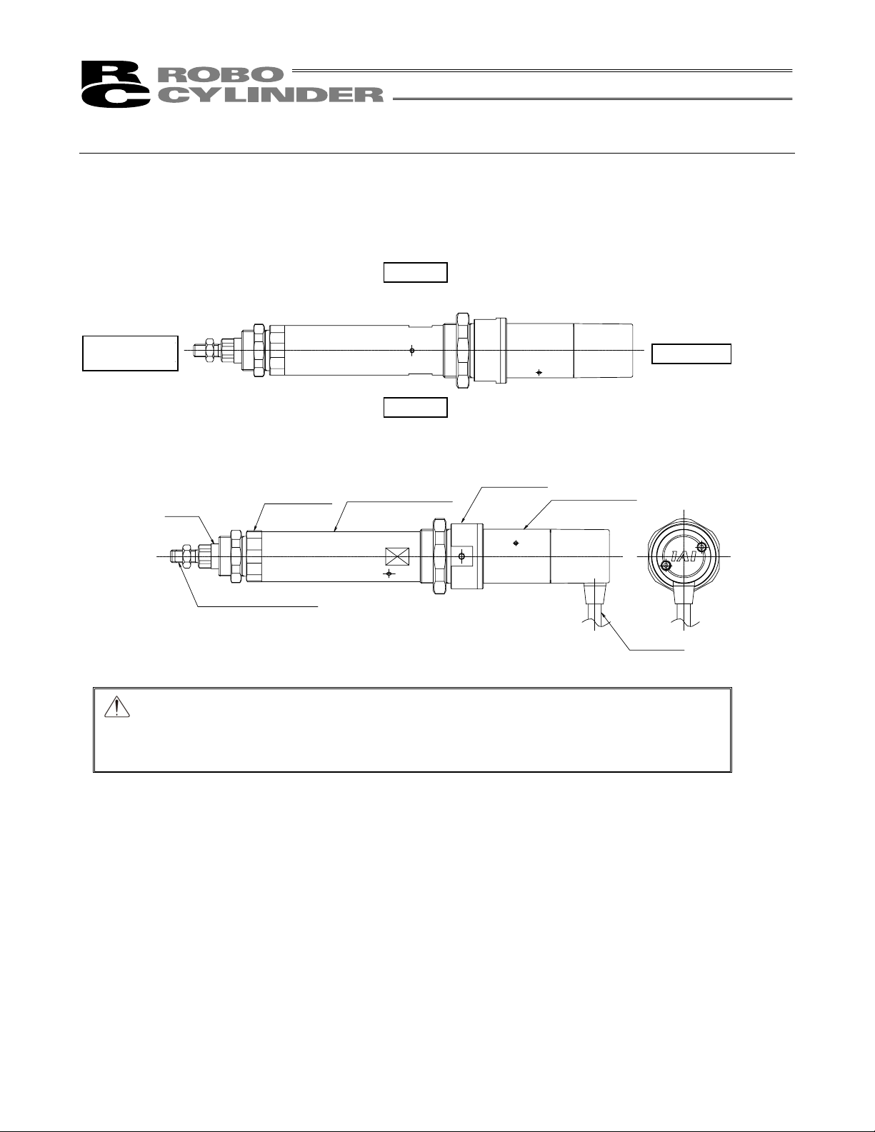
Names of the Parts
In this Operation Manual, the left and right sides are indicated by looking at the actuator from the motor end, with
the actuator placed horizontally, as shown in the figure below.
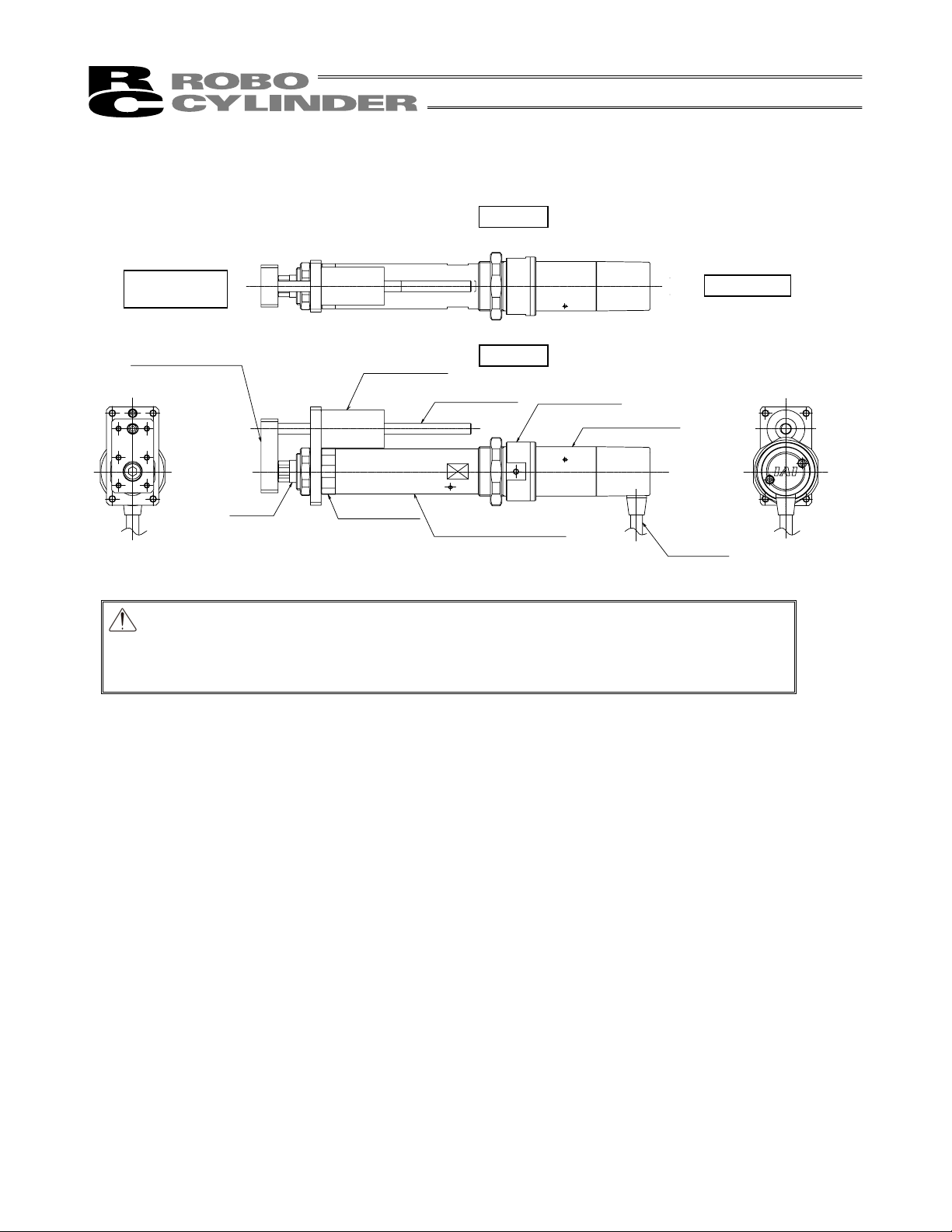
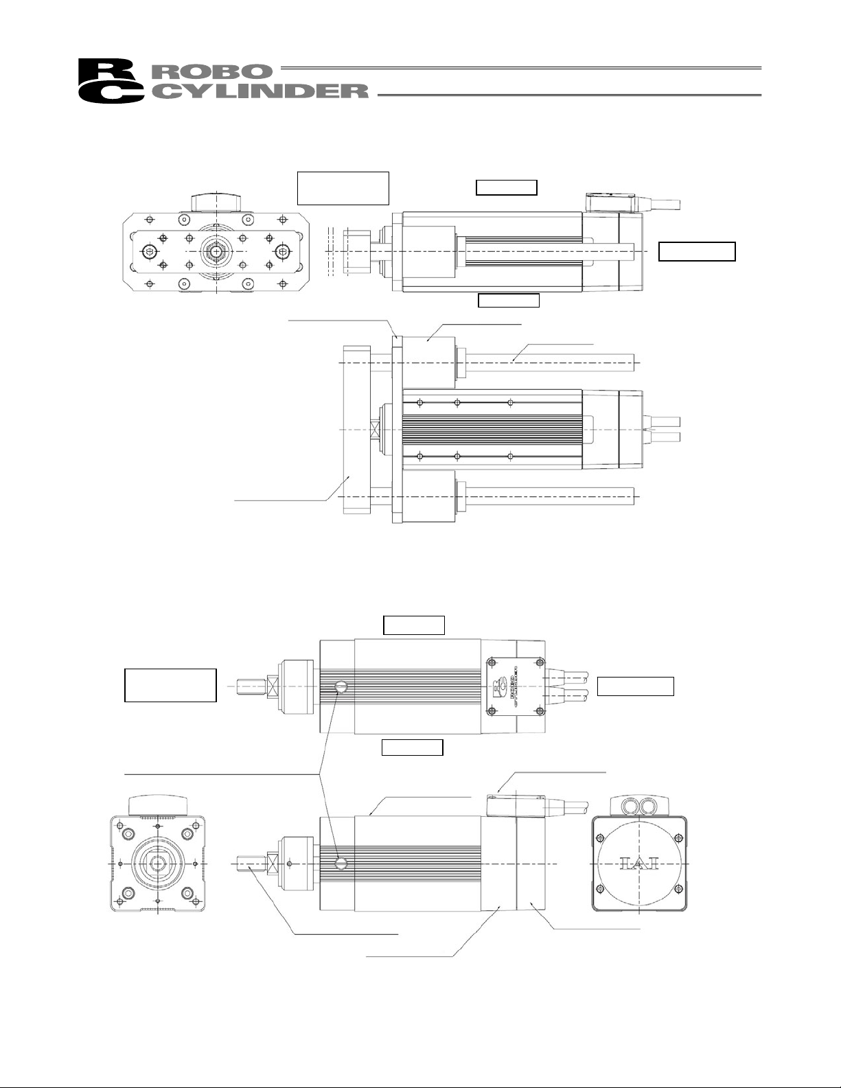
1. Motor Straight Type (Coupling Type): No Guide
z RCS2-RA4C
Right
Opposite side
of the Motor
Caution: The cable directly connected to the actuator is not robot cable even when ordered
Left
Rod
Rod tip adapter
with robot cable option. When designing, please be sure not to give repeated
bending loads to this cable. The robot cable is applicable only to the connecting
cables.
Rod cover
Cylinder tube
Head cover
Motor unit
Cable
Motor side
10
Page 19
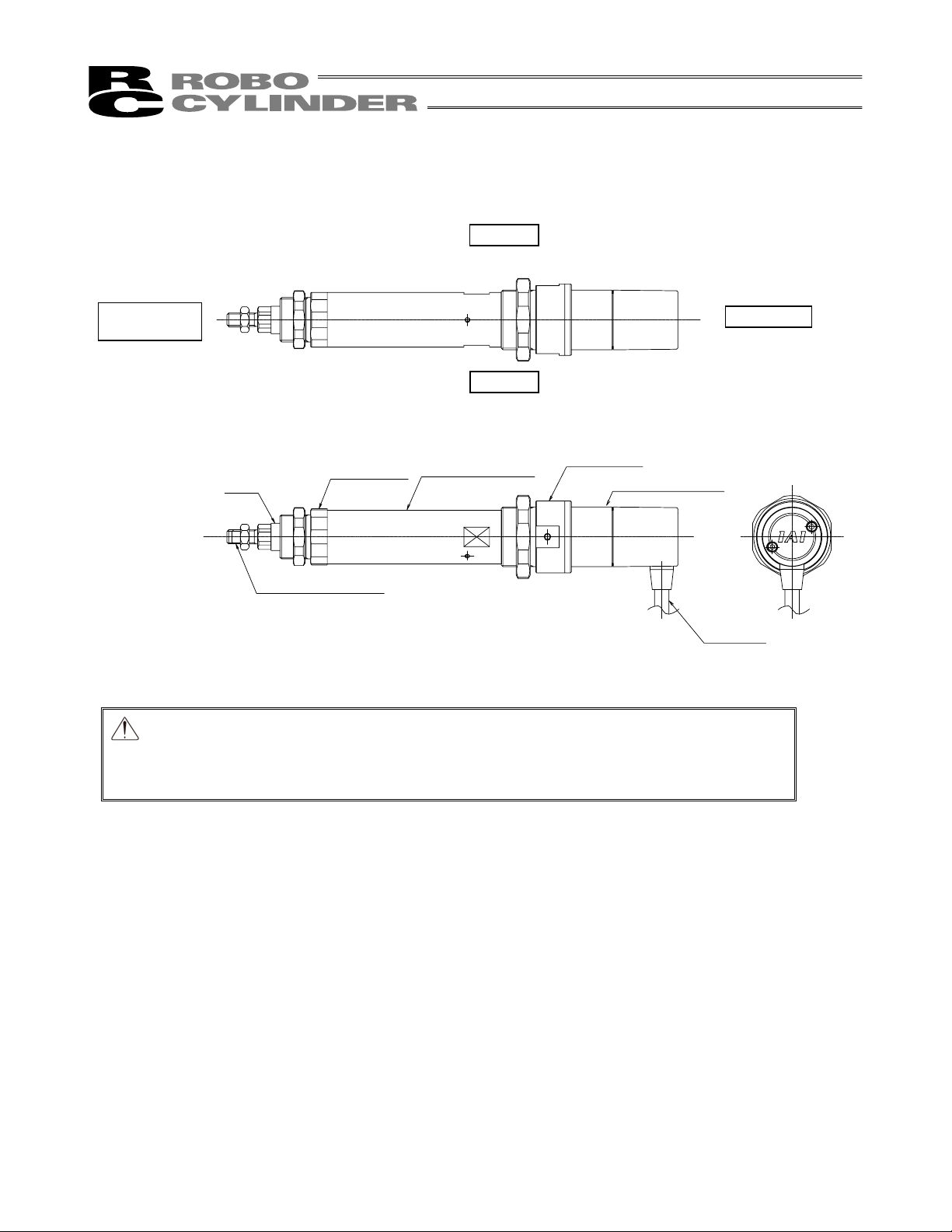
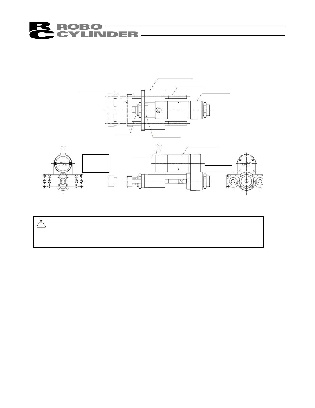
2. Motor Straight Type (Built-in Type): No Guide
z RCS2-RA4D
Right
Opposite side
of the Motor
Left
Head cover
Motor unit
Rod
Rod cover
Cylinder tube
Rod tip adapter
Caution: The cable directly connected to the actuator is not robot cable even when ordered
with robot cable option. When designing, please be sure not to give repeated
bending loads to this cable. The robot cable is applicable only to the connecting
cables.
Motor side
Cable
11
Page 20
r
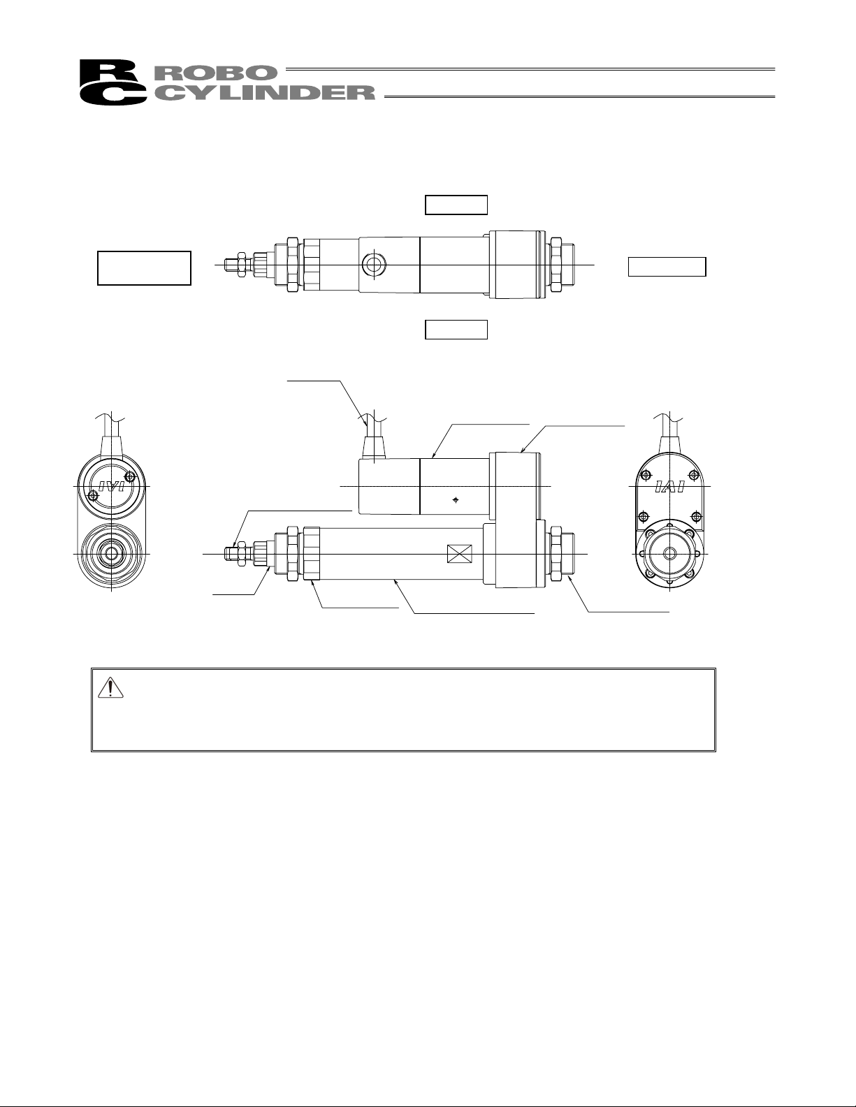
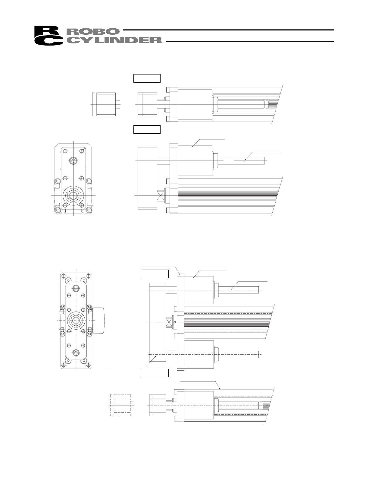
3. Motor Reversing Type: No Guide
z RCS2-RA4R
Right
Opposite side
of the Motor
Rod tip adapter
Rod
Cable
Rod cove
Left
Motor unit
Cylinder tube
Motor side
Pulley case
Head cover
12
Caution: The cable directly connected to the actuator is not robot cable even when ordered
with robot cable option. When designing, please be sure not to give repeated
bending loads to this cable. The robot cable is applicable only to the connecting
cables.
Page 21
4. Motor Straight Type (Coupling Type): Single-guide Type
z RCS2-RGS4C
Right
Opposite side
Motor side
of the Motor
Guide bracket
Guide bearing
Guide rod
Left
Head cover
Motor unit
Rod
Rod cover
Cylinder tube
Cable
Caution: The cable directly connected to the actuator is not robot cable even when ordered
with robot cable option. When designing, please be sure not to give repeated
bending loads to this cable. The robot cable is applicable only to the connecting
cables.
13
Page 22

5. Motor Straight Type (Coupling Type): Double-guide Type
z RCS2-RGD4C
Guide bracket
Opposite
side of
Guide bearing
Guide rod
Head cover
Right
Motor unit
Motor
side
the Motor
Left
Rod
Rod cover
Cylinder tube
Cable
Caution: The cable directly connected to the actuator is not robot cable even when ordered
with robot cable option. When designing, please be sure not to give repeated
bending loads to this cable. The robot cable is applicable only to the connecting
cables.
14
Page 23
r
r
6. Motor Reversing Type: With Double Guides
z RCS2-RGD4R
Guide bearing
Guide bracket
Rod
Rod cove
Guide rod
Head cove
Motor unit
Opposite
Cable
side of the
Motor
Motor side
Caution: The cable directly connected to the actuator is not robot cable even when ordered
with robot cable option. When designing, please be sure not to give repeated
bending loads to this cable. The robot cable is applicable only to the connecting
cables.
15
Page 24

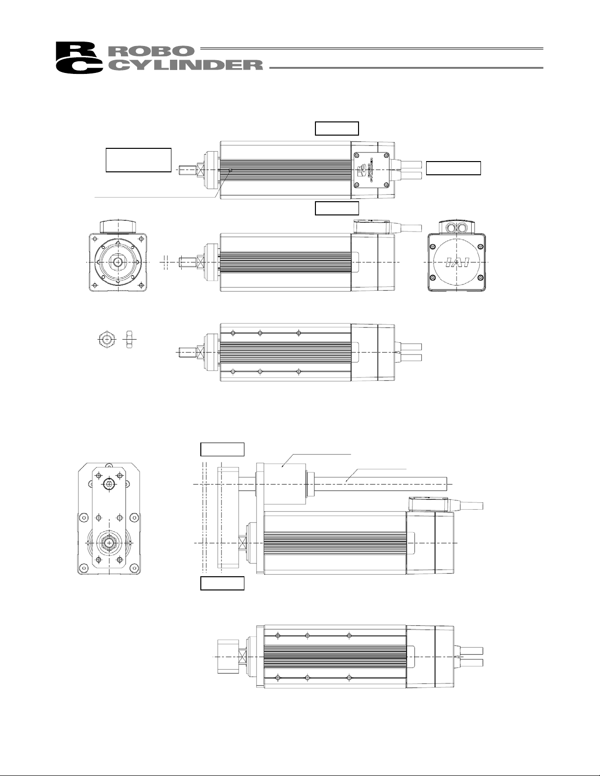
7. Motor Straight Type (Coupling Type): No Guide
z RCS2-RA5C
Right
Opposite side
of the Motor
Rod
Rod tip adapter
8. Motor Reversing Type: No Guide
z RCS2-RA5R
Right
Aluminum frame
Motor housing
Left
Pulley cover
Motor side
Connector box
Encoder cover
16
Left
Page 25
A
9. Motor Straight Type (Coupling Type): Single-guide Type
z RCS2-RGS5C
Right
Left
10. Motor Straight Type (Coupling Type): Double-guide Type
z RCS2-RGD5C
Mounting bracket
Right
Guide bearing
Guide rod
Guide bearing
Guide rod
Guide bracket
Left
luminum frame
17
Page 26
11. Short Type (Standard)
z RCS2-SRA7BD
Opposite side
of the Motor
Home position adjustment
screws (2 locations)
Never touch these screws.
Supplied nut (1 pc)
Right
Motor side
Left
12. Short Type: With Single Guide
z RCS2-SRGS7BD
Right
Left
Guide bearing
Guide rod
18
Page 27
13. Short Type: With Double Guides
z RCS2-SRGD7BD
Mounting bracket
Guide bracket
Opposite side
of the Motor
Right
L
f
Guide bearing
Motor side
Guide rod
14. Short Type
z RCS2-RA7A (B) D
Opposite side
of the Motor
Anti-vibration screws (4 locations)
Never touch these screws.
Rod tip adapter
Motor housing
RightRight
Motor side
Left
Connector box
Aluminum frame
Encoder cover
19
Page 28
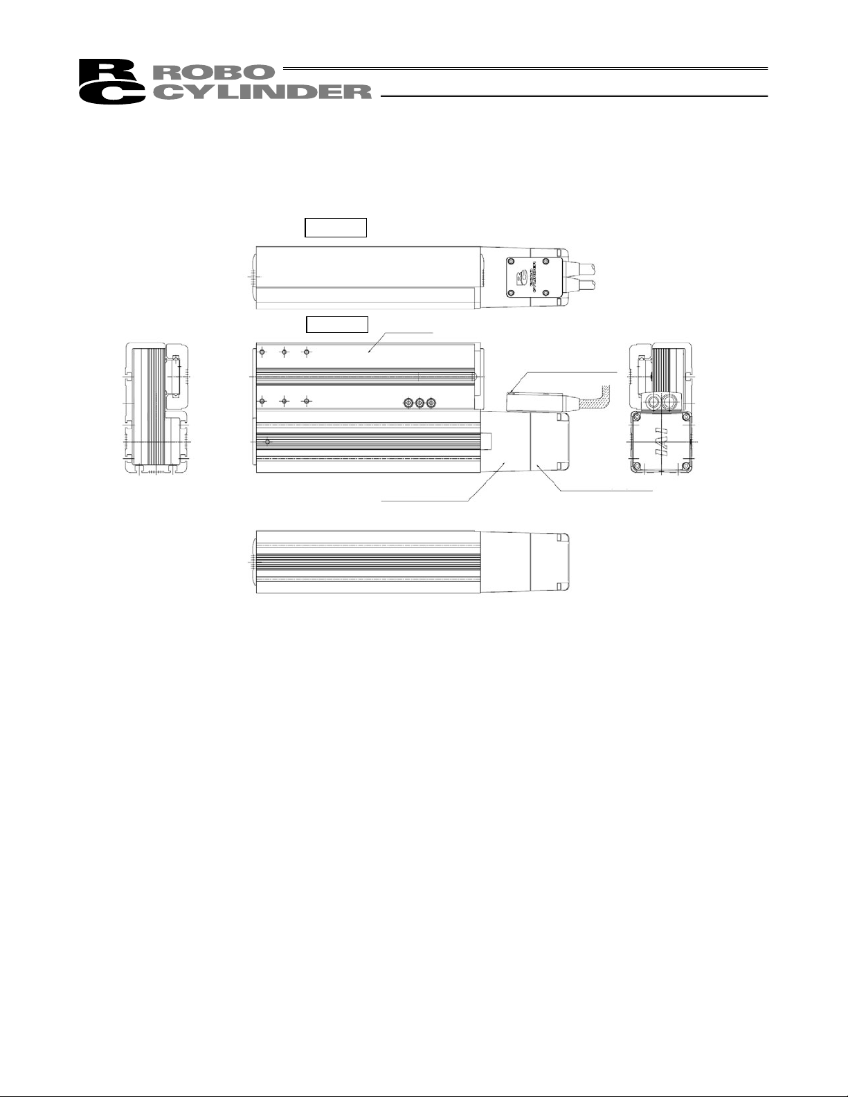
15. Flat Type
z RCS2-F5D
Right
Left
Slider
Motor housing
Connector box
Encoder cover
20
Page 29
r
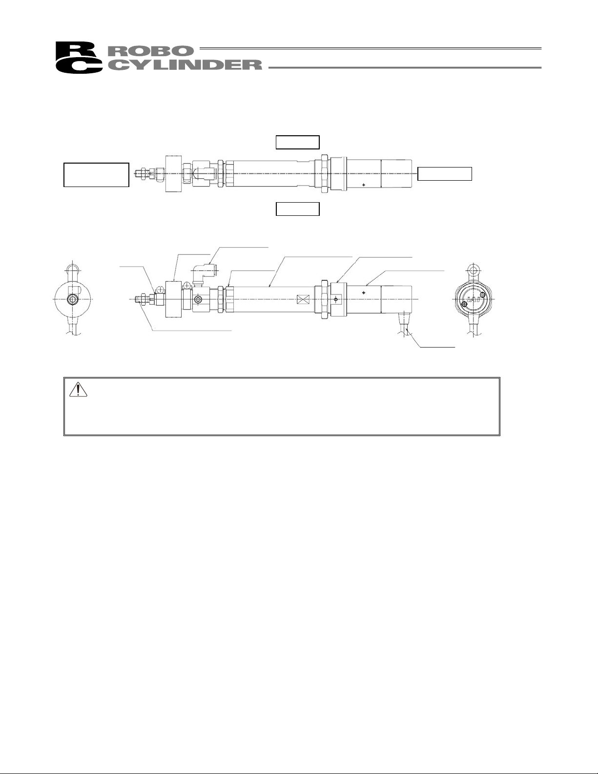
16. Dustproof/Splash-proof Motor Straight Type (Coupling Type)
z RCS2W-RA4C
Right
Opposite side
of the Motor
Motor side
Left
Intake/exhaust port
Rod
Bellows
Rod cover
Cylinder tube
Head cove
Motor unit
Rod tip adapter
Cable
Caution: The cable directly connected to the actuator is not robot cable even when ordered
with robot cable option. When designing, please be sure not to give repeated
bending loads to this cable. The robot cable is applicable only to the connecting
cables.
21
Page 30

22
Page 31

1. Specifications Check
1.1 Checking the Product
The standard configuration of this product is comprised of the following parts.
See the component list for the details of the enclosed components. If you find any fault or missing parts, contact
your local IAI distributor.
1.1.1 Parts
No. Name Model number Quantity Remarks
Refer to “How to Read the Model
1 Actuator
Nameplate” and “How to Read the
Model Number.”
Accessories
2 Motor • encoder cables
(Note1)
1 set
3 Nut Refer to list below
4 First Step Guide 1
5 Operation Manual (DVD) 1
6 Safety Guide 1
Note1 The motor • encoder cables differ between the standard model and robot cable.
[Refer to 1.4, Motor • Encoder Cables.]
[List of Included Nut Type]
Model No.
RCS2-RA7AD 1
RCS2-RA7BD 1
RCS2-SRA7BD 1
RCS2-RA5C
RCS2-RA5R 1
RCS2-RGD5C
*1
Stroke 100mm or less: 4 pieces, stroke more than 100mm: 8 pieces
Nut
M10u1.25
Nut
M12u1.25
Nut
M14u1.5
Nut
M20u1.5
Nut
M22u1.5
1
Square Nut
6u6 M4
Square Nut
7u7 M4
*1
4 or 8
*1
4 or 8
*1
4 or 8
Square Nut
10u10 M6
1. Specications Check
Model No.
RCS2-RA4C 1 1 1
RCS2-RA4D 1 1 1
RCS2-RA4R 2 1
RCS2-RGS4C 1 1
RCS2-RGS4D 1 1
Nut A
M26u1.5
Nut B
M35u1.5
Nut C
M8u1.5
Nut A
M30u1.5
Nut B
M40u1.5
Nut C
M10u1.5
23
Page 32

1.1.2 Operation Manuals for the Controllers Related to this Product
(1) XSEL-J/K Controller
No. Name Control No.
1 Operation Manual for XSEL-J/K Controller ME0116
2 Operation Manual for PC Software IA-101-X-MW/IA-101-X-USBMW ME0154
3 Operation Manual for Teaching Pendant SEL-T/TD/TG ME0183
4 Operation Manual for Teaching Pendant IA-T-X/XD ME0160
5 Operation Manual for DeviceNet ME0124
6 Operation Manual for CC-Link ME0123
1. Specications Check
7 Operation Manual for PROFIBUS ME0153
8 Operation Manual for X-SEL EtherNet ME0140
9 Operation Manual for Multi-Point I/O Board ME0138
10 Operation Manual for Multi-Point I/O Board Dedicated Terminal Board ME0139
(2) XSEL-P/Q Controller
No. Name Control No.
1 Operation Manual for XSEL-P/Q Controller ME0148
2 Operation Manual for XSEL-P/Q/PX/QX RC Gateway Function ME0188
3 Operation Manual for PC Software IA-101-X-MW/IA-101-X-USBMW ME0154
4 Operation Manual for Teaching Pendant SEL-T/TD/TG ME0183
5 Operation Manual for Teaching Pendant IA-T-X/XD ME0160
6 Operation Manual for DeviceNet ME0124
7 Operation Manual for CC-Link ME0123
8 Operation Manual for PROFIBUS ME0153
(3) SSEL Controller
No. Name Control No.
1 Operation Manual for SSEL Controller ME0157
2 Operation Manual for PC Software IA-101-X-MW/IA-101-X-USBMW ME0154
3 Operation Manual for Teaching Pendant SEL-T/TD/TG ME0183
4 Operation Manual for Teaching Pendant IA-T-X/XD ME0160
5 Operation Manual for DeviceNet ME0124
6 Operation Manual for CC-Link ME0123
7 Operation Manual for PROFIBUS ME0153
(4) SCON Controller and Related
No. Name Control No.
1 Operation Manual for SCON Controller ME0161
2 Operation Manual for SCON-CA Controller SCON-CA ME0243
3 Operation Manual for PC Software RCM-101-MW/RCM-101-USB ME0155
4 Operation Manual for Teaching Pendant CON-T/TG ME0178
5 Operation Manual for Touch Panel Teaching CON-PT/PD/PG ME0227
6 Operation Manual for Simplified Teaching Pendant RCM-E ME0174
7 Operation Manual for Data setter RCM-P ME0175
8 Operation Manual for Touch Panel Display RCM-PM-01 ME0182
9 Operation Manual for DeviceNet ME0124
10 Operation Manual for CC-Link ME0123
11 Operation Manual for PROFIBUS ME0153
24
Page 33

1.1.3 How to Read the Model Nameplate
r
Model
Serial numbe
MODEL RCS-RA4C-I-20-12-50-T1-P-B
SERIAL No.000090266 MADE IN JAPAN
1.1.4 How to Read the Model Number
(1) RCS2 Actuator
R C S 2 - R A 4 C - I - 2 0 - 1 2 - 5 0 - T 1 - P - B -
<Series Name>
Standard Type
RCS2
Dustproof/Splash proof type
RCS2W
<Type>
Standard Type
Coupling Type
RA4C, RA5C
Built-in Type
RA4D, SRA7BD
RA7AD, RA7BD
Motor Reversing Type
RA4R, RA5R
RA13R
With Single Guide Type
Coupling Type
RGS4C, RGS5C
Built-in Type
RGS4D, SRGS7BD
RGS7AD, RGS7BD
With Double Guides Type
Coupling Type
RGD4C, RGD5C
Built-in Type
RGD4D, SRGD7BD
RGD7AD, RGD7BD
Motor Reversing Type
RGD4R
Short Type
SRA7BD
With Single Guide Type
SRGS7BD
With Double Guides Type
SRGD7BD
<Encoder type>
I : Incremental
A : Absolute
TA : Absolute
<Motor Type>
20 : 20W
30 : 30W
60 : 60W
100 : 100W
150 : 150W
750 : 750W
<Lead>
1.25 : 1.25mm
2.5 : 2.5mm
3 : 3mm
4 : 4mm
6 : 6mm
8 : 8mm
12 : 12mm
16 : 16mm
<Stroke>
<Controller>
T1 : XSEL-J/K
T2 : SCON
SSEL
XSEL-P/Q
Identification for IAI use only
<Options>
B : Brake
FT : Foot Bracket
FL : Flange Bracket (Front)
FLR : Flange Bracket (Back)
HA : High Acceleration/Deceleration Type
HS : Home Position Confirmation Sensor
NJ : Knuckle Joint
NM : Reversed-home type
TRF : Trunnion Bracket (Front)
TRR : Trunnion Bracket (Rear)
QR : Clevis Bracket
RP : Rear Attachment Plate
A1 to A3:
Difference in Connector Cable Orientation
ML : Motor Reversing Type (Standard)
MR : Motor Reversing Type
GS2 to GS4:
Difference in Guide Attachment Orientation
RE : Rod Tip Extended Type
CE : CE Mark Complied
<Cable length>
N : None M : 5m
P : 1m XƑƑ : Specified Length
S : 3m RƑƑ : Robot Cable
(Note 1)
1. Specications Check
(2) Flat Type
R C S 2 - F 5 D - I - 6 0 - 1 6 - 5 0 - T 1 - P - B - * *
<Series Name>
<Type>
<Encoder type>
I : Incremental
A : Absolute
<Motor Type>
60 : 60W
100 : 100W
<Lead>
4 : 4mm
8 : 8mm
16 : 16mm
<Stroke>
Identification for IAI use only
<Options>
B : Brake
NM : Reversed-home type
<Cable length>
N : None
P : 1m
S : 3m
M : 5m
XƑƑ : Specified Length
RƑƑ : Robot Cable
CE : CE Mark Complied
<Controller>
T1 : XSEL-J/K
T2 : SCON
: SSEL
: XSEL-P/Q
(Note 1)
Note1 Identification for IAI use only: It may be displayed for IAI use. It is not a code to show the model type.
25
Page 34

1.2 Specification
1.2.1 Speed
Type Motor Type Lead [mm]
RCS2-RA4C,
RA4D, RA4R,
RGS4C, RGS4D,
RGD4C, RGD䋴D
RGD4R,
1. Specications Check
RCS2W-RA4C,
RA4D, RA4R
RCS2-RA5C,
RGS5C, RGD5C
RCS2-RA5R 60W
RCS2-RA7AD,
RGS7AD,
RGD7AD
RCS2-RA7BD,
RGS7BD,
RGD7BD
RCS2-SRA7BD,
SRGS7BD,
SRGD7BD
RCS2-F5D
20W
30W
60W
100W
60W
100W
100W
150W
60W
100W
150W
60W
100W
Speed limits [Unit: mm/s]
Horizontal/
Vertical
3
6
12
4
8
16
4
8
16
3
6
12
6
12
4
8
16
8
16
4
8
16
4
8
16
Horizontal 150
Vertical 150
Horizontal 300
Vertical 300
Horizontal 600
Vertical 600
Horizontal 200 188
Vertical 200 188
Horizontal 400 377
Vertical 400 377
Horizontal 800 755
Vertical 800 755
Horizontal 200 188
Vertical 200 188
Horizontal 400 377
Vertical 400 377
Horizontal 800 755
Vertical 800 755
Horizontal 150 125
Vertical 150 125
Horizontal 300 250
Vertical 300 250
Horizontal 600 505
Vertical 600 505
Horizontal 300 250
Vertical 300 250
Horizontal 600 505
Vertical 600 505
Horizontal 200
Vertical 200
Horizontal 400
Vertical 400
Horizontal 800
Vertical 800
Horizontal 400
Vertical 400
Horizontal 800
Vertical 800
Horizontal 200
Vertical 200
Horizontal 400
Vertical 400
Horizontal 800
Vertical 800
Horizontal 200
Vertical 200
Horizontal 400
Vertical 400
Horizontal 800
Vertical 800
50 to 250 300
Stroke [mm]
26
Page 35

1.2.2 Maximum acceleration and transportable weight
Type Motor Type Lead [mm]
20W
RCS2-RA4C
30W
20W
RCS2-RGS4C,
RGD4C
30W
20W
RCS2-RA4D,
RA4R,
RCS2W-RA4C,
RA4D, RA4R
30W
20W
RCS2-RGS4D,
RGD䋴D, RGD4R
30W
12
12
12
12
12
12
12
12
Maximum acceleration [G]
Horizontal/
Vertical
3
6
3
6
3
6
3
6
3
6
3
6
3
6
3
6
Horizontal 0.2 – 12.0 75.4
Vertical 0.2 – 4.0 75.4
Horizontal 0.3 1.0 6.0 37.7
Vertical 0.3 1.0 2.0 37.7
Horizontal 0.3 1.0 3.0 18.9
Vertical 0.3 1.0 1.0 18.9
Horizontal 0.2 – 18.0 113.1
Vertical 0.2 – 6.5 113.1
Horizontal 0.3 1.0 9.0 56.6
Vertical 0.3 1.0 3.0 56.6
Horizontal 0.3 1.0 4.0 28.3
Vertical 0.3 1.0 1.5 28.3
Horizontal 0.2 – 12.0 75.4
Vertical 0.2 – 3.5 75.4
Horizontal 0.3 1.0 6.0 37.7
Vertical 0.3 1.0 1.5 37.7
Horizontal 0.3 1.0 3.0 18.9
Vertical 0.3 1.0 0.5 18.9
Horizontal 0.2 – 18.0 113.1
Vertical 0.2 – 6.0 113.1
Horizontal 0.3 1.0 9.0 56.6
Vertical 0.3 1.0 2.5 56.6
Horizontal 0.3 1.0 4.0 28.3
Vertical 0.3 1.0 1.0 28.3
Horizontal 0.2 – 12.0 75.4
Vertical 0.2 – 4.0 75.4
Horizontal 0.3 – 6.0 37.7
Vertical 0.3 – 2.0 37.7
Horizontal 0.3 – 3.0 18.9
Vertical 0.3 – 1.0 18.9
Horizontal 0.2 – 18.0 113.1
Vertical 0.2 – 6.5 113.1
Horizontal 0.3 – 9.0 56.6
Vertical 0.3 – 3.0 56.6
Horizontal 0.3 – 4.0 28.3
Vertical 0.3 – 1.5 28.3
Horizontal 0.2 – 12.0 75.4
Vertical 0.2 – 3.5 75.4
Horizontal 0.3 – 6.0 37.7
Vertical 0.3 – 1.5 37.7
Horizontal 0.3 – 3.0 18.9
Vertical 0.3 – 0.5 18.9
Horizontal 0.2 – 18.0 113.1
Vertical 0.2 – 6.0 113.1
Horizontal 0.3 – 9.0 56.6
Vertical 0.3 – 2.5 56.6
Horizontal 0.3 – 4.0 28.3
Vertical 0.3 – 1.0 28.3
Standard
Type
High
Acceleration/
Deceleration
Type
(Model: HA)
Transportable
Weight [kg]
Rated Thrust
[N]
1. Specications Check
27
Page 36

Type Motor Type Lead [mm]
RCS2-RA5C
1. Specications Check
RCS2-RA5R 60W
RCS2-RGS5C,
RGD5C
RCS2-RA7AD
RCS2- RGS7AD
60W
100W
60W
100W
60W
100W
60W
100W
16
16
16
16
16
12
12
12
12
Maximum acceleration [G]
Horizontal/
Vertical
4
8
4
8
4
8
4
8
4
8
3
6
6
3
6
6
Horizontal 0.2 – 50.0 255.1
Vertical 0.2 – 11.5 255.1
Horizontal 0.3 1.0 25.0 127.5
Vertical 0.3 1.0 5.0 127.5
Horizontal 0.3 1.0 12.0 68.3
Vertical 0.3 1.0 2.0 68.3
Horizontal 0.2 – 60.0 424.3
Vertical 0.2 – 18.0 424.3
Horizontal 0.3 1.0 30.0 212.7
Vertical 0.3 1.0 9.0 212.7
Horizontal 0.3 1.0 15.0 105.8
Vertical 0.3 1.0 3.5 105.8
Horizontal 0.2 – 50.0 255.1
Vertical 0.2 – 11.5 255.1
Horizontal 0.3 – 25.0 127.5
Vertical 0.3 – 5.0 127.5
Horizontal 0.3 – 12.0 68.3
Vertical 0.3 – 2.0 68.3
Horizontal 0.2 – 50.0 255.1
Vertical 0.2 – 10.8 255.1
Horizontal 0.3 1.0 25.0 127.5
Vertical 0.3 1.0 4.3 127.5
Horizontal 0.3 1.0 12.0 68.3
Vertical 0.3 1.0 1.3 68.3
Horizontal 0.2 – 60.0 424.3
Vertical 0.2 – 17.3 424.3
Horizontal 0.3 1.0 30.0 212.7
Vertical 0.3 1.0 8.3 212.7
Horizontal 0.3 1.0 15.0 105.8
Vertical 0.3 1.0 2.8 105.8
Horizontal 0.05 – 40.0 340.1
Vertical 0.05 – 15.0 340.1
Horizontal 0.1 – 20.0 169.5
Vertical 0.1 – 7.0 169.5
Horizontal 0.15 – 10.0 85.3
Vertical 0.15 – 2.5 85.3
Horizontal 0.1 – 30.0 283.2
Vertical 0.1 – 12.5 283.2
Horizontal 0.2 – 15.0 141.1
Vertical 0.2 – 5.5 141.1
Horizontal 0.05 – 40.0 340.1
Vertical 0.05 – 14.5 340.1
Horizontal 0.1 – 20.0 169.5
Vertical 0.1 – 6.0 169.5
Horizontal 0.15 – 10.0 85.3
Vertical 0.15 – 1.5 85.3
Horizontal 0.1 – 30.0 283.2
Vertical 0.1 – 11.5 283.2
Horizontal 0.2 – 15.0 141.1
Vertical 0.2 – 4.5 141.1
Standard
Type
High
Acceleration/
Deceleration
Type
(Model: HA)
Transportable
Weight [kg]
Rated Thrust
[N]
28
Page 37

Type Motor Type Lead [mm]
60W
RCS2-RGD7AD
100W
100W
RCS2-RA7BD
150W
100W
RCS2-RGS7BD
150W
100W
RCS2-RGD7AD
150W
12
12
16
16
16
16
16
16
Maximum acceleration [G]
Horizontal/
Vertical
3
6
6
4
8
8
4
8
8
4
8
8
Horizontal 0.05 – 40.0 340.1
Vertical 0.05 – 13.9 340.1
Horizontal 0.1 – 20.0 169.5
Vertical 0.1 – 5.4 169.5
Horizontal 0.15 – 10.0 85.3
Vertical 0.15 – 0.9 85.3
Horizontal 0.1 – 30.0 283.2
Vertical 0.1 – 10.9 283.2
Horizontal 0.2 – 15.0 141.1
Vertical 0.2 – 3.9 141.1
Horizontal 0.1 – 40.0 424.3
Vertical 0.1 – 19.5 424.3
Horizontal 0.17 – 22.0 212.7
Vertical 0.17 – 9.0 212.7
Horizontal 0.25 – 10.0 105.8
Vertical 0.25 – 3.5 105.8
Horizontal 0.2 – 35.0 318.5
Vertical 0.2 – 14.5 318.5
Horizontal 0.3 – 15.0 158.8
Vertical 0.3 – 6.5 158.8
Horizontal 0.1 – 40.0 424.3
Vertical 0.1 – 18.5 424.3
Horizontal 0.17 – 22.0 212.7
Vertical 0.17 – 8.0 212.7
Horizontal 0.25 – 10.0 105.8
Vertical 0.25 – 2.5 105.8
Horizontal 0.2 – 35.0 318.5
Vertical 0.2 – 13.5 318.5
Horizontal 0.3 – 15.0 158.8
Vertical 0.3 – 5.5 158.8
Horizontal 0.1 – 40.0 424.3
Vertical 0.1 – 17.9 424.3
Horizontal 0.17 – 22.0 212.7
Vertical 0.17 – 7.4 212.7
Horizontal 0.25 – 10.0 105.8
Vertical 0.25 – 1.9 105.8
Horizontal 0.2 – 35.0 318.5
Vertical 0.2 – 12.9 318.5
Horizontal 0.3 – 15.0 158.8
Vertical 0.3 – 4.9 158.8
Standard
Type
High
Acceleration/
Deceleration
Type
(Model: HA)
Transportable
Weight [kg]
Rated Thrust
[N]
1. Specications Check
29
Page 38

Type Motor Type Lead [mm]
1. Specications Check
RCS-SRA7BD
60W
100W
150W
60W
100W
150W
16
16
16
16
16
16
Horizontal/
Vertical
4
8
4
8
4
8
4
8
4
8
4
8
Horizontal 0.05 – 20.0 254
Vertical 0.05 – 10.0 254
Horizontal 0.15 – 10.0 127
Vertical 0.15 – 5.0 127
Horizontal 0.25 – 5.0 63
Vertical 0.25 – 2.0 63
Horizontal 0.1 – 40.0 414
Vertical 0.1 – 19.5 414
Horizontal 0.2 – 22.0 207
Vertical 0.2 – 9.0 207
Horizontal 0.3 – 10.0 103
Vertical 0.3 – 3.5 103
Horizontal 0.1 – 55.0 628
Vertical 0.1 – 22.5 628
Horizontal 0.2 – 35.0 314
Vertical 0.2 – 14.5 314
Horizontal 0.3 – 15.0 157
Vertical 0.3 – 6.5 157
Horizontal – 0.15 10.0 254
Vertical – 0.15 5.0 254
Horizontal – 0.25 5.0 127
Vertical – 0.25 2.5 127
Horizontal – 0.35 2.5 63
Vertical – 0.35 1.0 63
Horizontal – 0.2 20.0 414
Vertical – 0.2 9.0 414
Horizontal – 0.3 10.0 207
Vertical – 0.3 4.5 207
Horizontal – 0.4 5.0 103
Vertical – 0.4 1.5 103
Horizontal – 0.2 27.5 628
Vertical – 0.2 11.0 628
Horizontal – 0.3 17.5 314
Vertical – 0.3 7 314
Horizontal – 0.4 7.5 157
Vertical – 0.4 3.0 157
Acceleration [G]
Rated
acceleration
Maximum
acceleration
Transportable
Weight [kg]
Rated Thrust
[N]
30
Page 39

Type Motor Type Lead [mm]
60W
100W
150W
RCS-SRGS7BD
60W
100W
150W
16
16
16
16
16
16
Horizontal/
Vertical
4
8
4
8
4
8
4
8
4
8
4
8
Horizontal 0.05 – 20.0 254
Vertical 0.05 – 9.5 254
Horizontal 0.15 – 10.0 127
Vertical 0.15 – 4.5 127
Horizontal 0.25 – 5.0 63
Vertical 0.25 – 1.5 63
Horizontal 0.1 – 40.0 414
Vertical 0.1 – 19.0 414
Horizontal 0.2 – 22.0 207
Vertical 0.2 – 8.5 207
Horizontal 0.3 – 10.0 103
Vertical 0.3 – 3.0 103
Horizontal 0.1 – 55.0 628
Vertical 0.1 – 22.0 628
Horizontal 0.2 – 35.0 314
Vertical 0.2 – 14.0 314
Horizontal 0.3 – 15.0 157
Vertical 0.3 – 6.0 157
Horizontal – 0.15 10.0 254
Vertical – 0.15 4.5 254
Horizontal – 0.25 5.0 127
Vertical – 0.25 2.0 127
Horizontal – 0.35 2.5 63
Vertical – 0.35 0.5 63
Horizontal – 0.2 20.0 414
Vertical – 0.2 8.5 414
Horizontal – 0.3 10.0 207
Vertical – 0.3 4.0 207
Horizontal – 0.4 5.0 103
Vertical – 0.4 1.0 103
Horizontal – 0.2 27.5 628
Vertical – 0.2 10.5 628
Horizontal – 0.3 17.5 314
Vertical – 0.3 6.5 314
Horizontal – 0.4 7.5 157
Vertical – 0.4 2.5 157
Acceleration [G]
Rated
acceleration
Maximum
acceleration
Transportable
Weight [kg]
Rated Thrust
[N]
1. Specications Check
31
Page 40

Type Motor Type Lead [mm]
1. Specications Check
RCS2-F5D
Caution: Do not attempt to establish the settings for the acceleration/deceleration above the allowable
range. It may cause vibration, malfunction or shortened life.
60W
100W
16
16
Maximum acceleration [G]
Horizontal/
Vertical
4
8
4
8
Horizontal 0.2 –
Vertical 0.2 – 11.5 255.1
Horizontal 0.3 –
Vertical 0.3 – 5.0 127.5
Horizontal 0.3 –
Vertical 0.3 – 2.0 63.8
Horizontal 0.2 –
Vertical 0.2 – 18.0 424.3
Horizontal 0.3 –
Vertical 0.3 – 9.0 212.7
Horizontal 0.3 –
Vertical 0.3 – 3.5 105.8
Standard
Type
High
Acceleration/
Deceleration
Type
(Model: HA)
Transportable
Weight [kg]
See the next
page
See the next
page
See the next
page
See the next
page
See the next
page
See the next
page
Rated Thrust
[N]
255.1
127.5
63.8
424.3
212.7
105.8
32
Page 41

[Moment and Transportable Weight of Flat Type (F5D)]
Shown in the table below is the allowable load on the tip calculated from Ma moment of each stroke.
Stroke 50 100 150 200 250 300
F5D Type
Distance from point of
action [m]
N 64.3 37.5 26.5 20.5 16.7 14.1
(kgf) 6.56 3.83 2.70 2.09 1.70 1.43
0.07 0.12 0.17 0.22 0.27 0.32
25
Distance from point of action
1. Specications Check
Point of Action
33
Page 42

1.2.3 Driving System • Position Detector
Type Motor Type
RCS2-RA4C, A4D, RA4R,
RGS4C, RGS4D, GD4C,
RGD4, RGD4R, CS2W-RA4C,
RA4D, RA4R
RCS2-RA5C, RGS5C,
RGD5C
1. Specications Check
RCS2-RA5R 60W
RCS2-RA7AD,
RGS7AD,
RGD7AD
RCS2-RA7BD,
RGS7BD,
RGD7BD
RCS2-SRA7BD,
SRGS7BD,
SRGD7BD
RCS2-F5D
20W
30W
60W
100W
60W
100W
100W
150W
60W
100W
150W
60W
100W
Lead
[mm]
3
6
12
4
8
16
4
8
16
3
6
12
6
12
4
8
16
8
16
4
8
16
4
8
16
No. of
Encoder
Pulses
16384
3072
16384 Bll Screw
Type Diameter Accuracy
Bll Screw
Bll Screw
Bll Screw
Bll Screw
Bll Screw
Bll Screw
Ball Screw Type
I10mm
I12mm
I12mm
I10mm
I12mm
I12mm
I12mm
C10
C10
C10
C10
C10
C10
C10
1.2.4 Positioning Precision
Type Lead [mm] Item Tolerance
RCS2-RA4C, RA4D, RA4R,
RGS4C, RGS4D, RGD4C,
RGD4, D4R, RCS2W-RA4C,
RA4D, RA4R
RCS2-RA5C,
RA5R, RGS5C,
RGD5C
RCS2-RA7AD,
RGS7AD,
RGD7AD
RCS2-RA7BD,
RGS7BD,
RGD7BD
RCS2-SRA7BD,
SRGS7BD,
SRGD7BD
RCS2-F5D
3
6
12
4
8
16
3
6
12
4
8
16
4
8
16
4
8
16
The values shown above are the accuracy at the delivery from the factory.
It does not include the consideration of time-dependent change as it is used.
Positioning Repeatability ±0.02mm
Lost Motion 0.1mm or less
Positioning Repeatability ±0.02mm
Lost Motion 0.1mm or less
Positioning Repeatability ±0.02mm
Lost Motion 0.1mm or less
Positioning Repeatability ±0.02mm
Lost Motion 0.1mm or less
Positioning Repeatability ±0.02mm
Lost Motion 0.1mm or less
Positioning Repeatability ±0.02mm
Lost Motion 0.05 or less
34
Page 43

1.2.5 Rod Non-Rotation Accuracy
Type Lead [mm] Tolerance
RCS2-RA4C,
RA4D, RA4R,
RCS2W-RA4C, RA4D,
RA4R
RCS2- RGS4C,
RGS4D
RGD4C, RGD䋴D
RCS2-RA5C,
RA5R
RCS2-RGS5C
RCS2-RGD5C
RCS2-RA7AD
RCS2-RGS7AD
RCS2-RGD7AD
RCS2-RA7BD
RCS2-RGS7BD
RCS2-RGD7BD
RCS2-SRA7AD
RCS2-SRGS7AD
RCS2-SRGD7AD
12
12
16
16
16
12
12
12
16
16
16
16
16
16
1. Specications Check
3
6
3
6
4
8
4
8
4
8
3
6
3
6
3
6
4
8
4
8
4
8
4
8
4
8
4
8
±1.0°
±0.05°
±0.7°
±0.1°
±0.08°
±0.7°
±0.1°
±0.08°
±0.7°
±0.1°
±0.08°
–
±0.1°
±0.08°
35
Page 44

1.2.6 Allowable Load Moment of Actuator
(1) Rod Type
x The actual load should not exceed the value specified in the catalog.
x Be sure to align the shaft center of the rod and the moving direction of the load.
x Lateral load may cause damage or breakdown of the actuator.
x If the rod may receive lateral load, provide a guide or other appropriate mechanism to support the
actuator in the moving direction of the load.
1. Specications Check
x Do not allow the rod (slide shaft) to receive rotational torque.
* Doing so may damage the internal parts.
Tighten the nut at the tip of the rod, while securely holding
the rod using a wrench of size 17 (RA4) or 22 (RA5).
36
Page 45

(2) Flat Type
Shown below is the dynamic allowable load moment when the driving life is 5000km.
1. Specications Check
Type
F5D 4.5 5.4 4.1
M
M
c
The point of action for the moment in directions Ma and Mb are as shown below.
Allowable Dynamic Load Moment [N•m]
Ma Mb Mc
B
M
A
F5D
44.5mm
Point of Action
1.2.7 Protection class
Type Performance
RCS2W-RA4C, RA4D, RA4R IP54
[Refer to 2.4 Connecting the Air Tube of the RCS2W Dustproof/Splash-proof Type for the details.]
37
Page 46

1.2.8 Duty Ratio in Continuous Operation
p
]
Continuous operation is available with the duty ratio 100%.
Duty ratio is the rate of operation expressed in % that presents the time of the actuator being operated in 1
cycle of operation.
Caution: If an overload error occurs, extend the stopped time to lower the duty or decrease
[How to Calculate Duty]
Figure out the load rate and acceleration/deceleration speed time ratio by calculation and read the duty ratio
1. Specications Check
from the graph. When the load rate is less than 50%, an operation with 100% duty ratio (continuous
operation) should be available.
1) Duty ratio LF
It is descried in 2. Specifications regarding the maximum transportable weight at the rated acceleration and
rated acceleration/deceleration.
theacceleration/deceleration speed.
Duty ratio: LF = [%]
M u D
Mr u Dr
Maximum transportable weight at the rated acceleration : Mr [kg]
Rated acceleration/deceleration : Dr [G]
Transferring mass during operation : M [kg]
Acceleration/deceleration during operation : D [kg]
2) Acceleration/deceleration time ratio t
Acceleration/deceleration time ratio tod = [%]
Velocity at
operation [mm/s]
Acceleration time = [sec] Deceleration time = [sec]
Acceleration [mm/s
Acceleration during
o
eration[mm/s
2
] = Acceleration [G] u 9,800mm/s
Deceleration [mm/s2] = Deceleration [G] u 9,800mm/s
od
Acceleration time
during operation
2
Deceleration time
+
during operation
Operation Time
2
2
Velocity at
operation [mm/s]
Deceleration during
operation [mm/s
2
]
3) Read the duty ratio from the load rate LF and the acceleration speed time ratio tod that were used to
figure out the duty ratio.
Example) If the load factor LF is 80% and acceleration/deceleration time ratio tod is 80%, the reference
duty is approx. 75%.
LF = Less than 50%
Approx
75%
50%
Reference of Operation Duty [%]
45 %
Acceleration/deceleration time ratio tod [%]
LF = 60%
LF = 70%
LF = 80%
LF = 90%
LF = 100%
High Accel/Decel Type
LF = 125%
High Accel/Decel Type
LF = 150%
High Accel/Decel Type
LF = 200%
High Accel/Decel Type
38
Page 47

1.3 Option
1.3.1 Brake Type (Model: B)
The brake is a mechanism designed to prevent the rod from dropping on a vertically installed actuator when the
power or servo is turned OFF.
Use the brake to prevent the installed load, etc., from being damaged due to the falling rod.
1.3.2 Reversed–home Specification (Model: NM)
The standard home position is on the motor side. This is the type to indicate when the operation direction is
required to be in the same as the coordinate system of the device that the actuator is mounted on.
Caution: The home position is adjusted at the factory before shipment. If you wish to change
the home after the delivery of your actuator, you must return the actuator to IAI for
adjustment. Contact our sales office or an agent near you.
1.3.3 Foot Bracket (Model: FT)
It is a metal part to be attached on the bottom of the actuator to affix with screws from top side.
RCS2-RA4R/RGS4R/RGD4R
Model code of single product: RCA-FT-RA4R
60
22
113.2
2-φ6.8
20
50.5
40
39
75
st
56
3
3
ME
Home
Nut A
ME
SE
9
20
10
115.5
82.5
9.5
10
37
φ
L1
L2
2-φ6.8
20
26
33
20
10
[RA4R]
L1st L2
50
125
100
175
150
225
200
275
250
325
300
375
[RGS4R/RGD4R]
L1st L2
50
133
100
183
150
233
200
283
250
333
300
383
198
248
298
348
398
448
206
256
306
356
406
456
RCS2-RA5C/RA5R/RGS5C/RGD5C
Model code of single product: RCS2-FT-RA5
20
80
68
55
55
84.5
12
7
φ
1. Specications Check
RCS2-SRA7BD
Model code of single product: RCS2-FT-SRA7
2×2-φ7
88
100
75
75
107
15
16.5
20
39
Page 48

1.3.4 Flange Bracket (Front) (Model: FL)
This is a metal component for flange to fix the unit on the rod side.
RCS2-RA4□
RCS2W-RA4□
Model code of single product:
RCA-FL-RA4
1. Specications Check
52.8
31
45
RCS2-SRA7BD
Model code of single product: RCS2-FL-SRA7
4-φ9
56
73
1
22
3
45
M30×1.5
(Effective Thread
Area = 17.5)
φ20
Rod O.D.
20
56
10
Nut
9
9
4
L
(Width across Flats)
36
Flange
RCS2-RA5□
Model code of single product: RCS2-FL-RA5
(55)
4-φ7
40
φ37
54.5
(55)
70
85
(55)
(72.5)
(52)
Home
(55)
12
M10×1.25
(Effective Thread
Area = 20)
st
4-φ6.8
3
Home
ME
SE
19
(Width across Flats)
37.5
ME
Nut
75
60
90
106
1.3.5 Flange Bracket (Rear) (Model: FLR)
This is a flange bracket to affix the unit body at the back (motor) side.
RCS2/RCS2W-RA4C/RA4D
Model code of single product: RCA-FLR-RA4
m56 19L1
90
Home
75
55
41
9
4-φ6.8
Nut B
φ37
Flange
16
47 (Width across Flats)
φ50
φ42
Dimension M
RCA
RCS2
st
50
100
150
200
250
300
L1
137
187
237
287
337
487
Incremental
Absolute
Incremental/
Absolute
20w
67.5
80.5
80.5
m
30w
82.5
95.5
95.5
RCS2/RCS2W-RA4R
Model code of single product:
RCA-FL-RA4
Home
L2
115.5
82.5
9.5
φ37
*The front flange and the
rear flange can be used in
common for the motor
reversing type.
20
26
98.5
50.5
4-φ6.8
48
60
75
45
31
M10, Depth 18
st L1 L2
50 125 234
100 175 284
150 225 334
200 275 384
250 325 434
300 375 484
Flange
φ42
φ50
33L156
40
Page 49

1.3.6 High Acceleration/Deceleration Type) (Model: HA)
The maximum acceleration (0.2G or 0.3G) for the standard type becomes 1.0G.
At the maximum acceleration 1.0G, operation with the same transportable weight as the standard type can be
performed.
The dedicated controller is required when operating a high acceleration/deceleration type actuator. The controller
differs from the standard type.
1.3.7 Home Position Confirmation Sensor (Model: HS)
A sensor to monitor the slider to see if it is certainly moved to the home position when a home-return is executed
gets attached on the actuator.
1.3.8 Knuckle Joint (Model: NJ)
This is a metal joint to make free movement (rotation) on the tip of the rod for when using a clevis or trunnion
bracket.
For RCS2-RA4□
Model code of single product: RCA-NJ-RA4
1. Specications Check
M10×1.25, Depth 13
20
Joint Pin
Joint S
20
30 30 11
Joint W
Nut
1.3.9 Trunnion Bracket (Front) (Model: TRF)
This is a bracket to make the cylinder follow when the movement of an object attached on the tip of the rod is
different from the direction of rod movement. Attach on the rod.
For RCS2-RA4□
Model code of single product:
RCA-TRF-RA4
66.4
40
Bracket B
64
94
M10×1.25
(Effective Thread
Area = 20)
3
ME
Home
SE
Nut C
19
(Width across Flats)
Bracket A
st
ME
φ20
Rod O.D.
22
40
3
55610
Ring
36 (Width across Flats)
9
10
55
74
φ37
M40×1.25
(Effective Thread
Area = 19.5)
22
47
(Width across Flats)
9.5
41
Page 50

1.3.10 Trunnion Bracket (Rear) (Model: TRR)
This is a bracket to make the cylinder follow when the movement of an object attached on the tip of the rod is
different from the direction of rod movement. Attach it on the back (motor) side.
1. Specications Check
1.3.11 Clevis Bracket (Model: QR)
This is a bracket to make the cylinder follow when the movement of an object attached on the tip of the rod is
different from the direction of rod movement.
For RCS2-RA4□
Model code of single product:
RCA-TRR-RA4
M10×1.25
(Effective Thread
Area = 20)
56
st
3
Home
ME
ME
SE
Nut C
19 (Width across Flats)
9
10
36 (Width across Flats)
φ37
Nut A
RCS2-RA4R
Model code of single product: RCA-QR-RA4
22
st
3
ME
Home
SE
Nut B
14
(Width across Flats)
3
ME
20
φ20 Rod O.D.
9 10
56
L
9.5
Nut A
32
(Width across Flats)
r
82.5
φ37
115.5
φ42
33
26
16
0
φ5
M30×1.5
(Effective Thread
Area = 17.5)
φ20
Rod O.D.
22
20
47 (Width across Flats)
10
28
Clevis
15
55
75
2-φ9
9.5
M4
40
107
26.4
50.5
87
40
77
66.5
40
st
48
98.5
50
100
150
200
250
300
125
175
225
275
325
375
L
242
292
342
392
442
492
1.3.12 Rear Attachment Plate (Model: RP)
This is a metal (plate) to affix the motor reversing type on the back side.
For RCS2-RA4R
42
Model code of single product: RCA-RP-RA4
st
ME
SE
Home
Nut B
14 (Width across Flats)
3
ME
9
56
Nut A
φ20 Rod O.D.
32 (Width across Flats)
10
115.5
82.5
9.5
φ37
L
26
φ42
φ50
33 2.5 50.5
0
30h9 (-0.052)
φ
98.5
4-M4
48
39
φ
Page 51

1.3.13 Difference in Connector Cable Orientation (Model: A1 to A3)
The direction of cable ejection is different.
Ejection on motor side (Standard)
■ No option indicated (Not Specified)
Left oriented ejection
■ Option indication:
A1
1. Specications Check
(Complied with SRA7BD)
Ejection on rod side
■ Option indication: A2 (Complied with RA5C/RA5R/SRA7BD)
Right oriented ejection
■ Option indication:
A3
(Complied with SRA7BD)
1.3.14 Motor Reversing Type (Standard) (Model: ML), Motor Reversing Type (Model: MR)
The direction of motor reversing is different. From the view of the motor side, the type with the motor reversed to
the left is ML, and the motor reversed to the right is MR
1.3.15 Difference in Guide Attachment Orientation (Model: GS2 to GS4)
The position of the rod for the single guided type is different. They are attached on the right (GS2), attached on
the bottom (GS3) and attached on the left (GS4).
1.3.16 Rod Tip Extended Type (Model: RE)
This is an adopter to extend the rod tip of RCS2-SRA7BD to have the same distance from the attachment hole to
the rod tip for RCS2-SRA4BD and RCS2-RA7BD.
1.3.17 CE Mark Complied (Model: CE)
It shows the compliance with CE Mark
43
Page 52

1.4 Motor • Encoder Cables
[1] Motor Cables/Motor Robot Cables
Model number: CB-RCC-MAƑƑƑ/CB-RCC-MAƑƑƑ-RB
ƑƑƑ indicates the cable length (L) (Example: 030=3m), Max.20m
(16) (20)
(41)
1. Specications Check
(Front View)
[Bending Radius]
When used under moving condition : 51mm (Robot Cable)
When used in fixed condition : 34mm (Standard Cable)
[2] Encoder Cables/Encoder Robot Cables (For X-SEL-J/K)
Model number: CB-RCBC-PAƑƑƑ/CB-RCBC-PAƑƑƑ-RB
ƑƑƑ indicates the cable length (L) (Example: 030=3m), Max.20m
(16)
(33)
4
1
Controller side
(57)
Width
0.75sq
9)
φ
(
Signal Name
PE
U
V
W
No.
1
2
3
4
8)
φ
(
L
(21)
Signal Name
No.
U
1
V
2
W
3
PE
4
L
(36)
Width
0.75sq
(Solderless)
(20)
1
4
Mechanical Side
1,10
(14)
(10)
(18)
(Front View)
(15)
(25)
(Front View)
Controller side
Width
Signal Name
A/U
A/U
B/V
B/V
Z/W
0.15sq
(Solderless)
The shield is clamped to the hood
Ground wire and braided shield wires
Z/W
SD
SD
BAT+
BATVCC
GND
BKBK+
―
No.
1
2
3
4
5
6
7
8
9
10
11
12
13
14
15
[Bending Radius]
When used under moving condition : 90mm (Robot Cable)
When used in fixed condition : 75mm (Standard Cable)
44
No.
10
11
12
13
14
15
16
17
18
1
2
3
4
5
6
7
8
9
Signal Name
A/U
A/U
B/V
B/V
Z/W
Z/W
―
―
FG
SD
SD
BAT+
BAT-
VCC
GND
―
BK-
BK+
Width
0.15sq
(Solderless)
9,18
(Front View)
Mechanical Side
Page 53

[3] Encoder Cables/Encoder Robot Cables (For SCON, SSEL and X-SEL-P/Q)
Model number: CB-RCS2-PAƑƑƑ/CB-X2-PAƑƑƑ
ƑƑƑ indicates the cable length (L) (Example: 030=3m), Max.20m
(41)
(13)
L
1. Specications Check
(14)
(15)
1
14
(37)
13
26
Controller side Mechanical Side
Electric Wire Color
Signal Name
Width
AWG26
(Soldered)
The shield is clamped to the hood
―
―
E24V
0V
LS
CLEEP
OT
RSV
―
―
―
A+
A-
B+
B-
Z+
ZSRD+
SRDBAT+
BAT-
VCC
GND
BKR-
BKR+
―
Orange/White
―
―
―
Gray/White
Brown/White
―
―
―
―
―
―
Pink
Purple
White
Blue/Red
Green/White
Blue
Orange
Black
Yellow
Green
Brown
Gray
Red
―
No.
10
11
12
13
26
25
24
23
18
19
14
15
16
17
20
21
22
1 10
(25)
9
18
(Front View)(Front View)
9
Electric Wire Color
1
2
3
4
5
6
7
8
Ground wire and braided shield wires
No.
1
2
3
4
5
Orange/White
6
Green/White
7
Brown/White
8
9
10
11
12
13
14
15
16
17
18
Purple
Blue/Red
Orange
Yellow
Brown
Gray/White
Pink
White
―
Drain
Blue
Black
Green
Gray
Red
Signal Name
A
A
B
B
Z
Z
LS+
―
FG
SD
SD
BAT+
BATVCC
GND
LSBK-
BK+
Width
AWG26
(Solderless)
[Bending Radius]
When used under moving condition : 58mm (Robot Cable)
When used in fixed condition : 93mm (Standard Cable)
45
Page 54

2. Installation
2.1 Transportation
[1] Handling of Robot
(1) Handling the Packed Unit
Unless otherwise specified, the actuator is shipped with each axis packaged separately.
2. Installation
x Do not damage or drop. The package is not applied with any special treatment that enables it to resist an
impact caused by a drop or crash.
x Transport a heavy package with at least more than two operators. Consider an appropriate method for
transportation.
x Keep the unit in horizontal orientation when placing it on the ground or transporting. Follow the instruction if
there is any for the packaging condition.
x Do not step or sit on the package.
x Do not put any load that may cause a deformation or breakage of the package.
(2) Handling the Actuator After Unpacking
x Do not carry an actuator by motor unit and a cable or attempt to move it by pulling the cable.
x Hold the body base when transporting the actuator.
x Be careful not to bump the actuator into anything when moving it.
x Do not apply an excessive force to each part of the actuator.Inparticular, prevent the motor unit and rear
bracket from receiving an unnecessary force.
Supplement) For the names of each part of the actuator, refer to “Names of the Parts”
46
Page 55

[2] Handling in Assembled Condition
x When carrying the actuator, exercise caution not to bump it against nearby objects or structures.
x Secure the rods to prevent sudden movement during transport.
x If any end of the actuator is overhanging, secure it properly to avoid significant movement due to external
vibration.
x When transporting the assembly without the ends of the actuators fastened, do not subject the assembly to an
impact of 0.3 G or more.
x When suspending the mechanical equipment (system) with ropes, avoid applying force to actuator, connector
box, etc. Also, avoid the cables being pinched or caused an excessive deformation.
2. Installation
47
Page 56

2.2 Installation and Storage • Preservation Environment
[1] Installation Environment
The actuator should be installed in a location other than those specified below.
In general, the installation environment should be one in which an operator can work without protective gear.
Also provide sufficient work space required for maintenance inspection.
x Where the actuator receives radiant heat from strong heat sources such as heat treatment furnaces
x Where the ambient temperature exceeds the range of 0 to 40qC
2. Installation
x Where the temperature changes rapidly and condensation occurs
x Where the relative humidity exceeds 85% RH
x Where the actuator receives direct sunlight
x Where the actuator is exposed to corrosive or combustible gases
x Where the ambient air contains a large amount of powder dust, salt or iron (at level exceeding what is normally
expected in an assembly plant)
x Where the actuator is subject to splashed water, oil (including oil mist or cutting fluid) or chemical solutions
x Where the actuator receives impact or vibration
If the actuator is used in any of the following locations, provide sufficient shielding measures:
x Where noise generates due to static electricity, etc.
x Where the actuator is subject to a strong electric or magnetic field
x Where the actuator is subject to ultraviolet ray or radiation
[2] Storage • Preservation Environment
x The storage and preservation environment should comply with the same standards as those for the installation
environment. In particular, when the machine is to be stored for a long time, pay close attention to
environmental conditions so that no dew condensation forms.
x Unless specially specified, moisture absorbency protection is not included in the package when the machine is
delivered. In the case that the machine is to be stored and preserved in an environment where dew
condensation is anticipated, take the condensation preventive measures from outside of the entire package, or
directly after opening the package.
x For storage and preservation temperature, the machine withstands temperatures up to 60qC for a short time,
but in the case of the storage and preservation period of 1 month or more, control the temperature to 50�C or
less.
x Storage and preservation should be performed in the horizontal condition. In the case it is stored in the
packaged condition, follow the posture instruction if any displayed on the package.
48
Page 57

2.3 How to Installation
r
r
r
This chapter explains how to install the actuator on your mechanical system.
2.3.1 Installation of Main Unit
The surface to mount the main unit should be a machined surface or a plane that possesses an equivalent
accuracy and the flatness should be within 0.05mm. Also, the platform should have a structure stiff enough to
install the unit so it would not generate vibration or other abnormality.
䎃
Also consider enough space necessary for maintenance work such as actuator replacement and inspection.
On the base there is a datum surface prepared for the attachment slotted holes.
On the back side of the actuator, there are attachment tapped holes, through holes, positioning reamed holes and
slotted holes. For the details of the positions and dimensions, check in the appearance drawings. [Refer to 6.
External Dimensions.]
When repeatability in re-attaching is required after it is detached, utilize the reamed holes. Please note, however,
that a consideration is necessary such as to use only one point on the motor side of the reamed holes when a
fine-tuning such as perpendicularity is required.
(1) Using screws on the rod or head side
Install the actuator using screws set on the rod or head side of the actuator.
z Applicable model: RCS2-RA4
Straight type
Rod cover
Cylinder tube
Head cove
2. Installation
Reversing type
Motor unit
Rod
Rod cove
RA4 type
Cylinder tube
Type MA MB
M30 u 1.5 M40 u 1.5
Pulley case
Head cove
49
Page 58

(2) Using screws on a flange (optional)
2. Installation
An optional flange is available for installing the actuator. Use this flange, if necessary.
z Applicable model: RCS2-RA4
Straight type
Mounting hole
Affixing nut
Flange
Mounting hole
Tightening torque 12.3 N•m 5.4 N•m
Straight type
Affixing nut
Flange
Mating material is steel Mating material is aluminum
Screw size M6 M6
50
Page 59

Affixing nut
Reversing type
2. Installation
Mounting hole
Flange
Reversing type
Affixing nut
Mounting hole
Flange
Mating material is steel Mating material is aluminum
Screw size M6 M6
Tightening torque 12.3 N•m 5.4 N•m
51
Page 60

2. Installation
䃂 Applicable models: RCS2-SRA7BD
Short type
Mating material is steel Mating material is aluminum
Screw size M6 M6
Tightening torque 12.3 N•m 5.4 N•m
52
Page 61

(3) Using screws on feet (optional)
Optional feet are available for installing the actuator. Use these feet, if necessary.
z Applicable model: RCS2-RA4
Mounting hole
Straight type
Affixing nut
Foot A
Mounting hole
Affixing nut
Foot B
Reversing type
2. Installation
Mounting hole
Mounting hole
Affixing nut
Affixing nut
Foot
Mating material is steel Mating material is aluminum
Screw size M6 M6
Tightening torque 12.3 N•m 5.4 N•m
Foot
53
Page 62

2. Installation
z Applicable model: RCS2-SRA7BD
Short type
Mating material is steel Mating material is aluminum
Screw size M6 M6
Tightening torque 12.3 N•m 5.4 N•m
Caution: Affix the actuator using two feet (optional), one in the front and the other in the
back.
If affixed using only one foot in the front or back, the actuator may be negatively
affected due to insufficient rigidity.
54
Page 63

(4) Using screws on a trunnion (optional)
An optional trunnion is available for installing the actuator. Use this trunnion, if necessary.
z Applicable model: RCS2-RA4
Straight type
Mounting hole
Affixing nut
Trunnion ring
2. Installation
Bracket B
Bracket A
Straight type
Mounting hole
Trunnion ring
Affixing nut
Bracket B
Bracket A
Mating material is steel Mating material is aluminum
Screw size M6 M6
Tightening torque 12.3 N•m 5.4 N•m
55
Page 64

2. Installation
Trunnion ring
Reversing type
Mounting hole
Affixing nut
Bracket B
Caution: • Exercise caution when installing the actuator horizontally using the optional
Bracket A
Mating material is steel Mating material is aluminum
Screw size M6 M6
Tightening torque 12.3 N•m 5.4 N•m
clevis or trunnion or any commercially available free joint, because the rod will
receive the actuator weight. As a result, the bush may wear quickly or internal
mechanical parts may be damaged.
If the actuator is installed horizontally using any of the aforementioned means,
add a guide or other appropriate mechanism to prevent the rod from receiving
the actuator weight.
• The optional clevis and trunnion are designed so that the fulcrum shaft can only
receive radial load. In a condition where play is not permitted or thrust load is
received, the customer must design a separate bearing structure.
• The optional clevis and trunnion provide structures whereby the bearing supports
the fulcrum shaft. Apply grease to the fulcrum shaft.
56
Page 65

(5) Using screws on a clevis (optional)
An optional clevis is available for installing the actuator. Use this clevis, if necessary.
z Applicable model: Motor reversing type RCS2-RA4R
Reversing type
Stopper ring
Stopper ring
2. Installation
Clevis bracket
Mounting hole
Mating material is steel Mating material is aluminum
Screw size M8 M8
Tightening torque 30 N•m 12 N•m
Caution: x Exercise caution when installing the actuator horizontally using the optional
clevis or trunnion or any commercially available free joint, because the rod will
receive the actuator weight. As a result, the bush may wear quickly or internal
mechanical parts may be damaged.
If the actuator is installed horizontally using any of the aforementioned means,
add a guide or other appropriate mechanism to prevent the rod from receiving
the actuator weight.
x The optional clevis and trunnion are designed so that the fulcrum shaft can only
receive radial load. In a condition where play is not permitted or thrust load is
received, the customer must design a separate bearing structure.
x The optional clevis and trunnion provide structures whereby the bearing supports
the fulcrum shaft. Apply grease to the fulcrum shaft.
57
Page 66

(6) Using screws on a rear mounting bracket (optional)
2. Installation
An optional rear mounting bracket is available for installing the actuator. Use this rear mounting bracket, if
necessary.
z Applicable model: Motor reversing type RA4R
Reversing type
Tapped mounting hole
Type Tapped hole diameter Tapped depth Tightening torque
RA4 type M4 7 mm 1.8 N•m
58
Page 67

(7) Double-guide type
Use the tapped holes in the bracket for installing an actuator of the double-guide type.
z Applicable model: Double-guide type RGD4
Tapped mounting hole
2. Installation
Bracket A
Type Tapped hole diameter Tapped depth Tightening torque
RA4 type M5 8 mm 3.4 N•m
z Applicable model: SRGD7BD
Tapped mounting hole
Bracket B
Bracket A
Bracket B
Type Tapped hole diameter Tapped depth Tightening torque
SRGD7BD M6 9 mm or more 5.36 N•m
59
Page 68

(8) Single-guide type
2. Installation
Use the tapped holes in the bracket for installing an actuator of the single-guide type.
z Applicable model: Double-guide type RGD4
Tapped mounting hole
Bracket A
Bracket B
Type Tapped hole diameter Tapped depth Tightening torque
RA4 type M5 8 mm 3.4 N•m
60
Page 69

(9) Using tapped mounting holes at the back
Applicable model: RA7 (excluding 50-mm stroke models)
The RA7 type has tapped mounting holes at the back.
Use these holes to install the actuator.
RA7
Shown below is the maximum screw-in depth of the tapping screws used for mounting the base.
Be careful not to allow the tip of the bolt to project.
Type Tapped hole diameter Maximum screw-in depth
RA7 M5 15 mm
SRA7BD, SRGS7BD, SRGD7BD M5 12 mm
2. Installation
(10) Using T-grooves and square nuts
Applicable models: RA5C, RA5R, F5D
The RA5 and F5 types have T-grooves. Insert square nuts in these T-grooves and install the actuator to the
frame.
T-grooves
Square nuts
61
Page 70

(11) Using feet
Applicable models: RA5, RA5R, RA7, SRA7BD, SRGS7BD, SRGD7BD (excluding flat types)
2. Installation
[1] On the RA7 type, attach feet using the
tapped mounting holes at the back.
Foot
Install the feet to the frame using bolts.
[2] On the RA5 type, attach feet using square
nuts inserted into the T-grooves.
Foot
(12) Using tapped holes on the reference surface
Applicable models: RA5, RA5R, RA7 (excluding flat types and guide types)
Type Tapped hole diameter Effective thread depth
RA5/RA5R M6 12 mm
RA7 M5 15 mm
SRA7BD M5 12 mm
62
Page 71

2.4 Connecting the Air Tube of the RCS2W Dustproof/Splash-proof Type
Intake/exhaust port
Install the air tube (outer diameter: 10 mm, inner diameter: 6.5 mm) on the intake/exhaust port and guide the air
tube to a location where the external environment assures the tube will not come in contact with water.
2. Installation
(Applicable tube)
Shown below is a representative model of air tube that can be installed on the RCS2W:
x TU1065: Polyurethane tube (Manufacturer: SMC)
Caution: The air tube should not be more than 3 m long.
63
Page 72

3. Connecting with Controller
As the connection cable for the controller and RCS2 (this actuator), use the IAI-dedicated controller and
dedicated connection cable.
This section explains the wiring method for a single axis.
x If the dedicated connection cable cannot be secured, reduce the load on the cable by allowing it to deflect only
by the weight of the cable or wire it in a self-standing cable hose, etc., having a large radius.
x Do not cut and reconnect the dedicated connection cable for extension or shorten the cable.
x Do not pull on the dedicated connection cable or bend it forcibly.
x The actuator cable coming out of the motor unit is not meant to be bent. Fix the cable so it would not be bent
repeatedly.
Please consult with IAI if you require a different kind of cable than the one supplied.
[Connection with SCON/SSEL Controllers]
3. Connecting with Controller
Dedicated controllers
SCON
SSEL
Dedicated cables
x Motor cable CB-RCC-MA*** / Robot motor cable CB-RCC-MA***-RB
x Encoder cable CB-RCS2-PA*** / Robot encoder cable CB-X3-PA***-RB
*** indicates the cable length. A desired length up to 30 m can be specified.
Example) 080 = 8 m
[Connection with X-SEL Controllers]
RCS2, RCS2W
RCS2, RCS2W
Dedicated cables
(Connecting the RCS2 or RCS2W
with a dedicated controller)
r
r
Robot cable
r = 58 mm or more (movable)
Standard cable
r = 93 mm or more (fixed)
Use a robot cable for sections where the cable will move.
Dedicated cables
(Connecting the RCS2 or RCS2W
with a dedicated controller)
r
r
Robot cable
Dedicated controllers
XSEL
r = 58 mm or more (movable)
Standard cable
r = 93 mm or more (fixed)
Use a robot cable for sections where the cable will move.
Dedicated cables
x Motor cable CB-RCC-MA*** / Robot motor cable CB-RCC-MA***-RB
x X-SEL-J/K encoder cable CB-RCBC-PA*** / X-SEL-J/K robot encoder cable CB-RCBC-PA***-RB
x X-SEL-P/Q encoder cable CB-RCS2-PA*** / X-SEL-P/Q robot encoder cable CB-X3-PA***-RB
*** indicates the cable length. A desired length up to 15 m can be specified.
For other cables, a desired length up to 20 m can be specified.
Example) 080 = 8 m
64
Page 73

Warning: For wiring, please follow the warnings stated below. When constructing a system
as the machinery equipment, pay attention to the wiring and connection of each
cable so they are conducted properly. Not following them may cause not only a
malfunction such as cable breakage or connection failure, or an operation error,
but also electric shock or electric leakage, or may even cause a fire.
• Use dedicated cables of IAI indicated in this instruction manual. Contact us if you wish to
have a change to the specifications of the dedicated cables.
• Make sure to turn the power off in the process of power line or cable connection or
disconnection.
• Do not attempt to cut a dedicated cable with connectors on both ends to extend, shorten
or re-joint it.
• Hold the dedicated cable to avoid mechanical force being applied to the terminals and
connectors.
• Use a cable pipe or duct to have an appropriate protection when there is a possibility of
mechanical damage on a dedicated cable.
• In case a dedicated cable is to be used at a moving part, make sure to lay out the cable
without applying any force to pull the connector or extreme bend on the cable. Do not
attempt to use the cable with a bending radius below the allowable value.
• Make certain that the connectors are plugged properly. Insufficient connection may cause
an operation error, thus it is extremely risky.
• Do not lay out the cables to where the machine runs over them.
3. Connecting with Controller
• Pay attention to the cable layout so it would not hit peripherals during an operation. In
case it does, have an appropriate protection such as a cable track.
• When a cable is used hanging on the ceiling, prevent an environment that the cable
swings with acceleration or wind velocity.
• Make sure there is not too much friction inside the cable storage equipment.
• Do not apply radiated heat to power line or cables.
• Have a sufficient radius for bending, and avoid a bend concentrating on one point.
Steel Strap
(Piano Wire)
Tie them up softly.
65
Page 74

• Do not let the cable bend, kink or twist.
• Do not pull the cable with a strong force.
• Pay attention not to concentrate the twisting force to one point on a cable.
3. Connecting with Controller
• Do not pinch, drop a heavy object onto or cut the cable.
• When a cable is fastened to affix, make sure to have an appropriate force and do not
tighten too much.
Do not use spiral tube in any
position where cables are bent
frequently.
66
Page 75

• PIO line, communication line, power and driving lines are to be put separately from each
other and do not tie them together. Arrange so that such lines are independently routed in
the duct.
Power Line
Duct
I/O Line
(Flat Cable, etc.)
Follow the instructions below when using a cable track.
• If there is an indication to the cable for the space factor in a cable track, refer to the wiring
instruction given by the supplier when storing the cable in the cable track.
• Avoid the cables to get twined or twisted in the cable track, and also to have the cables
move freely and do not tie them up. (Avoid tension being applied when the cables are
bent.)
Do not pile up cables. It may cause faster abrasion of the sheaths or cable breakage.
3. Connecting with Controller
67
Page 76

4. Maintenance Inspection
4.1 Inspection Items and Schedule
Follow the maintenance inspection schedule below.
It is assumed that the equipment is operating 8 hours per day.
If the equipment is running continuously night and day or otherwise running at a high operating rate, inspect more
often as needed.
Visual inspection Grease supply
Start of operation
After 1 month of operation
After 3 months of operation
Every 3 months thereafter
After 3 years of operation, or upon
reaching 5,000 km in traveled distance
Every year thereafter
4. Maintenance Inspection
Note 1 Apply grease to the sliding surface of the rod at the startup check if grease has been consumed, or
every three months.
For the RCS2W dustproof/splash-proof type, apply grease when the bellows is changed.
Note 2 [Applicable Units: RCS2-RA5C, RA5R, RGS5C, RGD5C, SR7BD, SRGS7BD, SRGD7BD]
4.2 External Visual Inspection
{
{
{
{
{
{
{ (Sliding surface of the rod
{ (Sliding surface of the rod
(Note 1)
(Note 1)
, Ball screw
, Ball screw
(Note 2)
(Note 2)
)
)
An external visual inspection should check the following things.
Main unit Loose actuator mounting bolts, other loose items
Rod Lubrication, dust, foreign object on sliding surfaces
Cables Scratches, proper connections
Overall Irregular noise, vibration
4.3 Cleaning
Ɣ Clean exterior surfaces as necessary.
Ɣ Use a soft cloth to wipe away dirt and buildup.
Ɣ Do not blow too hard with compressed air as it may cause dust to get in through the gaps.
Ɣ Do not use oil–based solvents as they can harm lacquered and painted surfaces.
Ɣ To remove severe buildup, wipe gently with a soft cloth soaked in a neutral detergent or alcohol.
68
Page 77

4.4 Grease Supply
䎃
4.4.1 Grease to be applied on Rod Sliding Surface
IAI uses the following grease in our plant.
Kyodo Yushi Multitemp LRL 3
Warning: Never use any fluorine-based grease. Mixing lithium-based grease with other grease not only
reduces the performance of the grease, it may even cause damage to the actuator.
4.4.2 Grease Applied on Ball Screw and Rod Sliding Surface
[Applicable Units: RCS2-RA5C, RA5R, RGS5C, RGD5C,SR7BD, SRGS7BD, SRGD7BD]
IAI uses the following grease in our plant.
Kyodo Yushi Multitemp LRL 3
This product is suitable for ball screws and has excellent properties such as low heat generation. Use a lithium
grease spray for maintenance. Keep the spraying time to within 1 second per spray action.
Wako Chemical Grease spray No.A161 or equivalent
Warning: x Never use any fluorine-based grease. It will cause a chemical reaction when mixed with a
lithium-based grease and may cause damage to the actuator.
x Keep the spraying time to within 1 second, and do not spray continuously for more than 1
second or spray more than twice repeatedly. It may create problems.
4. Maintenance Inspection
69
Page 78

4.4.3 How to apply grease
[1] Applying the Grease on the Rod Sliding Surface
Apply grease over the entire surface of the rod.
4. Maintenance Inspection
[2] Grease Supply on Ball Screw and Rod Sliding Surface
[Applicable Units: RCS2-RA5C, RA5R, RGS5C, RGD5C]
1) Remove the thin-head screw located at the position shown to below.
70
Page 79

2) Move the rod by at least one half the stroke.
Apply grease to the ball screw by spraying grease through the screw hole (by keeping the spraying time to
within 1 second).
Use your finger to apply grease over the rod sliding surface.
3) After grease has been applied, move the rod back and forth to let the grease spread evenly.
4. Maintenance Inspection
4) Apply silicon to the thread of the screw removed in (1), and then put the screw back into its original place.
Caution: x Do not use spray oil when applying grease. Be sure to use spray grease instead. Keep the
spraying time to within 1 second, and do not spray continuously for more than 1 second or spray
more than twice repeatedly. Also note that if an excess amount of grease is supplied, oil may
flow into the electronic components and cause malfunction.
x In case the grease got into your eye, immediately go see the doctor to get appropriate care.
After finishing the grease supply work, wash your hands carefully with water and soap to rinse
the grease off.
71
Page 80

[3] Grease Supply to Rod Sliding Surface and Ball Screw
䎃
䎃
䎃
䎃
[Applicable Units: RCS2-SRA7BD, SRGS7BD, SRGD7BD]
䎃
[Rod sliding surface]
䎃
1) Move the rod to the stroke end with such as JOG operation in advance.䎃
2) Turn the power off.䎃
3) Apply grease evenly on the rod sliding surface.䎃
䎃 At this time, apply grease with soft cloth so the rod sliding surface would not get damaged with scratches.䎃
4) Turn the power on, and run the rod back and forth for several times with such as JOG operation so the
grease spreads out to the whole area of the rod sliding surface.䎃
4. Maintenance Inspection
Rod sliding surface
72
Page 81

[Ball Screw]
䎃
1) Move the rod in advance with such as JOG operation to get it in the position where the distance between the
end of the stopper spacer and the end of the aluminum flame is approximately 10mm.䎃
2) Turn the power off.䎃
3) Move the urethane stopper to the body end. (the urethane stopper can be moved with hand.)
4) A hole for grease supply can be seen in the rod.䎃
5) Remove the hex socket head cap screw that covers the grease supply hole with a 1.5mm-sized hex wrench.䎃
6) Insert the nozzle of the grease spray to the grease supply hole and spray it. The time to spray should be 1
second at maximum.䎃
7) Tighten the hex socket head cap screw to the rod with a 1.5mm-sized wrench, and move the urethane
stopper to the stopper spacer end.䎃
8) Push the rod firmly against the mechanical stopper on the other side of the home position (the side that the
rod comes out).䎃
9) Move the rod to the stroke range.䎃
10) Turn the power on, and run the rod back and forth for several times with such as JOG operation so the
grease spreads out to the whole area of the ball screw.䎃
䎃
Urethane stopper
Stopper spacer
Grease supply hole
4. Maintenance Inspection
Approx. 10mm
Aluminum frame
Hex socket head cap screw (M3)
Caution: x Do not use an oil spray when in grease supply. Make sure to use a grease spray.䎃
Time to spray should be 1 second at maximum. Do not attempt to spray more than 1 second in
one shot, or spray 2 times or more at once. Excessive grease supply may cause the oil flow to
the electrical components, which may lead to an unexpected operation.
x In case the grease got into your eye, immediately go see the doctor to get appropriate care.
After finishing the grease supply work, wash your hands carefully with water and soap to rinse
the grease off.
䎃
73
Page 82

4.5 Procedure for Belt Replacement and Tuning
Applicable Untis : RCS2-RA4R, RA5R
4.5.1 Inspection of the Belt
For inspection work, detach the cover of a pulley case and carry it out by visual.
The replacement period cannot be determined in general because the durability of the deceleration belt can be
greatly influenced by the conditions of operation.
It generally has life of hundreds of times for bending movement.
The timing belt requires replacement regularly under the following conditions as a reference since degradation
such as abrasion proceeds as the time passes for usage.
x When remarkable abrasion is confirmed on the teeth or edges of the belt
x When the belt is swelled for such reasons as oil being attached on
x When damage is confirmed such as crack on the tooth or back of the belt
Also, since it is difficult to confirm the degradation of the core wires to retain the strength of the teethed belt by
visual or looseness caused by being elongated, it is recommended to set regular replacement periods in advance
in case the product is used under such conditions that gives the core wires great fatigue due to high acceleration
4. Maintenance Inspection
and deceleration speed.
4.5.2 Belts to be used
The following belt is applied when the product is shipped out from IAI factory.
x RA4R - 60S2M152R Rubber, cleanroom type (Bando Chemical Industries) 6 mm wide
x RA5R - 100S3M219R Rubber, cleanroom type (Bando Chemical Industries) 10 mm wide
74
Page 83

4.5.3 Adjusting the Belt Tension (RA4R Type)
Remove the pulley case cover and loosen the four motor-unit affixing bolts.
Pass a looped string (or long tie-band) around the motor unit, and pull the string to the specified tension using a
tension gauge. In this condition, uniformly tighten the motor-unit affixing bolts.
[Recommended tightening torque of adjustment bolts]
162 N•cm (16.5 kgf•cm)
Tension: 2.5 kgf
4. Maintenance Inspection
Motor-unit affixing bolts
(Use an Allen wrench of 2.5 mm across flats.)
Motor-unit affixing bolts
(Use an Allen wrench of 2.5 mm across flats.)
75
Page 84

4.5.4 Adjusting the Belt Tension (RA5R Type)
Remove the pulley case cover and loosen the four motor-unit affixing bolts.
Pass a looped string (or long tie-band) around the motor unit, and pull the string to the specified tension using a
tension gauge. In this condition, uniformly tighten the motor-unit affixing bolts.
[Recommended tightening torque for adjustment bolts]
4. Maintenance Inspection
Tension: 6 r 0.2 kgf
Motor-unit affixing bolts
(Use an Allen wrench of 3
mm across flats.)
76
Page 85

p
4.5.5 Replacing the Belt: RA4R Type
[Items Required for Replacement]
x Replacement belt
RA4R … 60S2M152R Rubber, cleanroom type (Bando Chemical Industries) 6 mm wide
x Allen wrenches
x Tension gauge (capable of tensioning to 7 kgf or greater)
x Strong string, looped (or long tie-band)
x Scale
x Oil-based marker pen
x PC or teaching pendant
[Overview of Replacement]
1) Move the rod to a position where Z phase turns on (home position) (2 mm from the mechanical end). In this
position, loosen the motor-unit affixing bolts and replace the belt.
2) Restore the home position.
Affix the rod at a position 2 mm from the mechanical end on the home side, pass the belt, and adjust the belt to
the specified tension.
3) Perform homing using a PC or teaching pendant and check for deviation from the initial home position.
If there is a deviation, adjust the home offset
X-SEL controller, adjust the home preset
if you are using an SCON controller. If you are using an SSEL or
.
4. Maintenance Inspection
Home position
Set by the home offset parameter (SCON) or home preset
parameter (SSEL, X-SEL).
(The above value indicates the factory setting.)
Z phase ON
osition
1 mm
The countermark on the motor
aligns with this position.
Approx. 2 mm
Mechanical end
77
Page 86

[Procedure]
1) Remove the pulley case cover using two Allen wrenches, one of 2 mm across flats and the other of 3 mm
across flats.
M4 hexagon socket
head screws
M3 hexagon socket
head screws
4. Maintenance Inspection
2) Move the rod to a position where Z phase turns on (home position).
This corresponds to a position where the rod projects 2 mm from the mechanical end.
Apply countermarks in this position.
Warning: If the actuator is installed vertically, move it after turning on the controller power
Cause the rod to project 2 mm from the mechanical end.
2 mm
Apply countermarks once the rod has projected
2 mm from the mechanical end.
and forcibly releasing the brake. At this time, beware of danger as the actuator
may drop suddenly.
Always provide a support to brace the actuator hand to prevent sudden drop, so
as not to pinch fingers or damage the load.
78
Page 87

3) Loosen the motor-unit affixing bolts using an Allen wrench of 2.5 mm across flats. Slide the motor, and loosen
and remove the belt.
(Use an Allen wrench of 2.5 mm across flats.)
Motor-unit affixing bolts
Motor-unit affixing bolts
(Use an Allen wrench of 2.5 mm across flats.)
4) Check the following points before restoring the home position:
x The motor side should be aligned with the initial countermark. If the position is offset, adjust it to achieve
proper alignment.
x The ball-screw side should be at a position where the rod projects 2 mm from the mechanical end.
After the check, attach a new belt while holding the pulleys on both sides in position.
4. Maintenance Inspection
Initial countermark position
Motor side
Corresponding to a position where
the rod projects 2 mm from the
mechanical end
Ball-screw side
79
Page 88

5) Adjust the belt tension.
Pass a looped strong string (or long tie-band) around the motor cover and pull it with a tension gauge to the
specified tension. In this condition, uniformly tighten the motor-unit affixing bolts.
[Recommended tightening torque for adjustment bolts]
162 N•cm (16.5 kgf•cm)
Tension: 2.5 kgf
4. Maintenance Inspection
Motor-unit affixing bolts
(Use an Allen wrench of 2.5 mm across flats.)
80
Motor-unit affixing bolts
(Use an Allen wrench of 2.5 mm across flats.)
Page 89

6) Install the pulley case cover using two Allen wrenches, one of 2 mm across flats and the other of 3 mm across
flats.
M4 hexagon socket
head screws
M3 hexagon socket
head screws
7) Connect a PC or teaching pendant to the controller to perform homing. (If the actuator is of absolute encoder
specification, an absolute reset must be performed.)
Check for deviation from the initial home position.
If there is a deviation, adjust parameter No. 22, “Home offset
” if you are using an SCON controller. If you are
using an SSEL or X-SEL controller, adjust axis-specific parameter No. 12, “Home preset.” If your controller is
of absolute encoder specification, perform homing after changing the parameter, and then perform an absolute
reset.
4. Maintenance Inspection
81
Page 90

p
4.5.6 Replacing the Belt: RA5R Type
[Items Required for Replacement]
x Replacement belt
RA5R … 100S3M219R Rubber, cleanroom type (Bando Chemical Industries) 10 mm wide
x Allen wrenches
x Tension gauge (capable of tensioning to 8 kgf or greater)
x Strong string, looped (or long tie-band)
x Scale
x Oil-based marker pen
x PC or teaching pendant
[Overview of Replacement]
1) Move the rod to a position where Z phase turns on (home position) (2 mm from the mechanical end). In this
position, loosen the motor-unit affixing bolts and replace the belt.
2) Restore the home position.
Affix the rod at a position 4 mm from the mechanical end on the home side, pass the belt, and adjust the belt to
the specified tension.
3) Perform homing using a PC or teaching pendant and check for deviation from the initial home position.
4. Maintenance Inspection
If there is a deviation, adjust the home offset
X-SEL controller, adjust the home preset
if you are using an SCON controller. If you are using an SSEL or
.
Mechanical end
Home position
2 mm
Set by the home offset parameter (SCON) or home preset
parameter (SSEL, X-SEL).
(The above value indicates the factory setting.)
Z phase ON
osition
2 mm
The countermark on the motor aligns
with this position.
82
Page 91

[Procedure]
(
)
1) Move the slider from the home position toward the mechanical end and check the rotating direction of the
motor shaft. (If the actuator has its home located on the opposite side to the standard specification, this check
is always required because the motor shaft rotates in the different direction.)
x Remove the pulley case cover.
(Remove the three thin-head screws using an Allen wrench of 2.5 mm across flats.)
Check the rotating direction of
the motor shaft.
4. Maintenance Inspection
2) Loosen the four tension adjustment bolts to
3) Remove the belt from the pulleys.
slacken the belt.
Allen wrench of 3 mm across flats
4) Make the following adjustment to restore the home position:
x Move the slider to the mechanical end on the home side and keep it in contact with the mechanical end.
x Turn the motor shaft by the specified amount from the countermark position toward the
return-to-mechanical-end direction (the direction checked at the beginning).
Type
RA5R-16
RA5R-8
RA5R-4
Amount returned from the
countermark position
67.5q
135q
230q
83
Page 92

5) Adjust the belt tension.
Pass a looped strong string (or long tie-band) around the motor cover and pull it with a tension gauge to the
specified tension. In this condition, uniformly tighten the motor-unit affixing bolts.
Recommended tightening torque for adjustment bolts: (M5) 763 N-cm (78 kgf-cm)
Caution: After tightening the bolts to the above torque, tighten them slightly further by making
sure that both pulleys do not move.
4. Maintenance Inspection
6) Install the pulley cover.
Tighten the three hexagon socket head bolts (M3x22) using an Allen wrench of 2.5 mm across flats.
Tension: 6 r 0.2 kgf
7) Perform homing using a PC or teaching pendant.
(If the actuator is of absolute encoder specification, an absolute reset must be performed). Check for deviation
from the initial home position.
If there is a deviation, adjust parameter No. 22, “Home offset
” if you are using an SCON controller. If you are
using an SSEL or X-SEL controller, adjust axis-specific parameter No. 12, “Home preset.” If your controller is
of absolute encoder specification, perform homing after changing the parameter, and then perform an absolute
reset.
84
Page 93

4.6 Replacing the Motor
4.6.1 Replacing the Motor of the Motor Straight Type (Coupling Type): RA4C Type
[Items Required for Replacement]
x Replacement motor unit
x Coupling (with screws)
x Allen wrenches
x Scale
x Oil-based marker pen
x Grease
Idemitsu Kosan Daphne Eponex Grease No.2
x PC or teaching pendant
[Overview of Replacement]
1) Move the rod to a position where Z phase turns on (home position) (2 mm from the mechanical end). In this
position, replace the motor.
2) Perform homing using a PC or teaching pendant and check for deviation from the initial home position.
If there is a deviation, adjust the home offset
X-SEL controller, adjust the home preset.
Home position
if you are using an SCON controller. If you are using an SSEL or
Z phase ON
position
Mechanical end
Replacement motor unit
Coupling (with screws)
4. Maintenance Inspection
1 mm
The countermark on the motor
aligns with this position.
Set by the home offset parameter (SCON) or home preset
parameter (SSEL, X-SEL).
(The above value indicates the factory setting.)
Approx. 2 mm
85
Page 94

[Procedure]
1) Move the rod to a position where Z phase turns on (home position).
This corresponds to a position where the rod projects 2 mm from the mechanical end.
Apply countermarks in this position.
4. Maintenance Inspection
Cause the rod to project 2 mm from the mechanical end.
2 mm
Apply countermarks once the rod has
projected 2 mm from the mechanical end.
Warning: If the actuator is installed vertically, move it after turning on the controller power
and forcibly releasing the brake. At this time, beware of danger as the actuator
may drop suddenly.
Always provide a support to brace the actuator hand to prevent sudden drop, so
as not to pinch fingers or damage the load.
2) Using an Allen wench of 2 mm across flats, remove the two motor-unit affixing bolts on the right and left.
2 affixing bolts on the motor-end
cap (right and left) (hexagon
socket head setscrews)
86
Page 95

3) Pull out the motor unit.
Before pulling out the motor unit, apply a countermark on the cylinder tube at a position corresponding to the
tab on the motor unit, so that the motor unit and cylinder can be aligned in the correct position later on.
Apply a countermark at a
Tab on the motor unit
position corresponding to
the tab on the motor unit.
4. Maintenance Inspection
4) Apply grease on the actuator coupling.
Apply grease on the inside
of the coupling.
87
Page 96

5) Align the tab on the replacement motor unit with the countermark on the cylinder.
With the motor unit and cylinder aligned properly, insert the coupling into the replacement motor unit by
aligning the orientation of this coupling with that of the actuator coupling (adjusted to a position corresponding
to a rod projection of 2 mm from the mechanical end). Apply countermarks to identify the current motor
position (phase Z position) and coupling.
Align the tab on the
replacement motor unit
with the countermark on
the cylinder.
4. Maintenance Inspection
Coupling
Replacement
motor unit
Position the couplings.
After the coupling has been
inserted, apply countermarks on
the replacement motor unit and
coupling.
88
Page 97

6) Turn the coupling and motor shaft simultaneously until a setscrew on the coupling is seen through the hole.
Thereafter, tighten the hexagon socket head setscrew using an Allen wrench of 2 mm across flats.
Similarly, turn the coupling and motor shaft simultaneously until the other screw is seen through the hole, and
tighten the setscrew.
4. Maintenance Inspection
Coupling
setscrew hole
Turn the coupling and motor shaft
simultaneously until a setscrew on the
coupling is seen through the hole.
Thereafter, tighten the hexagon socket head
setscrew using an Allen wrench of 2 mm
across flats.
89
Page 98

7) Return the coupling in the replacement motor unit to the initial motor position (Z phase position).
Align the tab on the replacement motor unit with the countermark on the cylinder. With the motor unit and
cylinder positioned this way, confirm that the orientation of the actuator coupling (adjusted to a position
corresponding to a rod projection of 2 mm from the mechanical end) corresponds to the position of the
coupling in the replacement motor unit.
Coupling
Replacement
motor unit
4. Maintenance Inspection
Apply countermarks on
the replacement motor
unit and coupling.
Align the tab on the
replacement motor unit
with the countermark on
the cylinder.
90
Confirm that the coupling
positions correspond.
Page 99

8) Carefully insert the replacement motor unit into the cylinder by ensuring that the couplings do not lose their
alignment.
9) Using an Allen wench of 2 mm across flats, tighten the two motor-unit affixing bolts on the right and left.
2 affixing bolts on the motor-end
cap (right and left) (hexagon
socket head setscrews)
4. Maintenance Inspection
10) Connect a PC or teaching pendant to the controller to perform homing. (If the actuator is of absolute encoder
specification, an absolute reset must be performed).
Check for deviation from the initial home position.
If there is a deviation, adjust parameter No. 22, “Home offset
” if you are using an SCON controller. If you are
using an SSEL or X-SEL controller, adjust axis-specific parameter No. 12, “Home preset.” If your controller is
of absolute encoder specification, perform homing after changing the parameter, and then perform an
absolute reset.
91
Page 100

p
4.6.2 Replacing the Motor of the Motor Reversing Type: RA4R Type
[Items Required for Replacement]
x Replacement motor unit
x Allen wrenches
x Tension gauge (capable of tensioning to 7 kgf or greater)
x Strong string, looped (or long tie-band)
x Scale
x Oil-based marker pen
x PC or teaching pendant
4. Maintenance Inspection
Replacement motor unit
[Overview of Replacement]
1) Loosen the motor-unit affixing bolts to remove the belt, and replace the motor.
2) Restore the home position.
Affix the rod at a position 2 mm from the mechanical end on the home side, pass the belt, and adjust the belt to
the specified tension.
3) Perform homing using a PC or teaching pendant and check for deviation from the initial home position.
If there is a deviation, adjust the home offset
X-SEL controller, adjust the home preset
Home position
1 mm
Set by the home offset parameter (SCON) or home preset
parameter (SSEL, X-SEL).
(The above value indicates the factory setting.)
if you are using an SCON controller. If you are using an SSEL or
.
Z phase ON
osition
Approx. 2 mm
The countermark on the motor
aligns with this position.
Mechanical end
92
 Loading...