

Page 1

ROBO Cylinder
RCS2 Actuator
Rotary
Hollow Rotary
Operating Manual
Fourth Edition
Rotary, RT6, RT6R, RT7R
Hollow Rotary, RTC8L, RTC8HL, RT10L, RTC12L
IAI America, Inc.
Page 2

Page 3

Please Read Before Use
Thank you for purchasing our product.
This Operation Manual describes all necessary info rmation to operate this product safely such as the
operation procedure, structure and maintenance procedure.
Before operation, read this manual carefully and fully understand it to operate this product safely. The
enclosed CD or DVD in this product package includes the Operation Manual for this product.
For the operation of this product, print out the necessary sections in the Operation Manual or display them
using the personal computer.
After reading through this manual, keep this Manual at hand so that the operator of this
product
can read it whenever necessary.
Operation
[Important]
Operation
This
The product cannot be operated in any way unless expressly specified in this
IAI shall assume no responsibility for the outcome of any operation not specified herein.
Information contained in this
purpose of product improvement.
If you have any question or comment regarding the content of this manual, please contact the
IAI sales office near you.
Using or copying all or part of this
The company names, names of products and trademarks of each company shown in the
sentences are registered trademarks.
Manual is original.
Operation
Operation
Manual is subject to change without notice for the
Operation
Manual without permission is prohibited.
Manual.
Page 4

Page 5

Table of Contents
Safety Guide.................................................................................................................... 1
Handling Precautions ...................................................................................................... 8
International Standards Compliances
............................................................................ 10
Names of the Parts........................................................................................................ 11
1. Checking the Product .............................................................................................. 14
1.1 Components ............................................................................................................................... 14
1.2 Operation Manuals for Controllers Relating to This Product...................................................... 14
1.3 How to Read the Nameplate ...................................................................................................... 16
1.4 How to Read the Model Number................................................................................................ 16
2. Specifications .......................................................................................................... 17
2.1 Rotary......................................................................................................................................... 17
2.2 Hollow Rotary ............................................................................................................................. 18
3. Installation Environment, Storage/Preservation Environment.................................. 19
3.1 Installation Environment............................................................................................................. 19
3.2 Storage Environment/Preservation ............................................................................................ 19
4. Installation ............................................................................................................... 20
4.1 Rotary Type ................................................................................................................................ 20
4.1.1 Installing the Actuator.................................................................................................... 20
4.2 Hollow Rotary ............................................................................................................................. 22
4.2.1 Installing the Actuator and a Tool on the Output Shaft.................................................. 22
4.2.2 Installation Direction and Mounting Surface.................................................................. 25
4.2.3 Load Offset Distance..................................................................................................... 26
5. Connecting to the Controller.................................................................................... 27
5.1 Wiring ......................................................................................................................................... 27
6. Notes on Operation ................................................................................................. 30
6.1 Rotary......................................................................................................................................... 30
6.1.1 Backlash and Positioning Accuracy Repeatability.........................................................30
6.1.2 Operation Range and Home Return ............................................................................. 30
6.1.3 Conditions for Loads Installable to Shaft of Rotary ....................................................... 32
6.2 Hollow Rotary ............................................................................................................................. 33
6.2.1 Operation Range and Home Return ............................................................................. 33
6.2.2 Brake ............................................................................................................................. 34
Page 6

7. How to Select a Hollow Rotary Actuator Model ....................................................... 35
8. Options.................................................................................................................... 37
8.1 Limit Switch ................................................................................................................................ 37
8.2 Brake .......................................................................................................................................... 37
8.3 Reversed-home Specification ....................................................................................................37
9. Motor/Encoder Cables............................................................................................. 38
10. Maintenance/Inspection .......................................................................................... 40
10.1 Inspection Items and Schedule.................................................................................................. 40
10.2 Visual Inspection of the Exterior................................................................................................. 41
10.3 Exterior Cleaning........................................................................................................................ 41
10.4 Adding Grease to the Hollow Rotary Gears............................................................................... 41
11. External Dimensions ............................................................................................... 44
11.1 Rotary ....................................................................................................................................... 44
11.2 Hollow Rotary............................................................................................................................. 47
12. Warranty.................................................................................................................. 50
Change History.............................................................................................................. 52
Page 7

Safety Guide
“Safety Guide” has been written to use the machine safely and so prevent personal injury or property
damage beforehand. Make sure to read it before the operation of this product.
Safety Precautions for Our Products
The common safety precautions for the use of any of our robots in each operation.
No.
1 Model
Operation
Description
Selection
Description
This product has not been planned and designed for the application where
high level of safety is required, so the guarantee of the protection of
human life is impossible. Accordingly, do not use it in any of the following
applications.
1) Medical equipment used to maintain, control or otherwise affect human
life or physical health.
2) Mechanisms and machinery designed for the purpose of moving or
transporting people (For vehicle, railway facility or air navigation facility)
3) Important safety parts of machinery (Safety device, etc.)
Do not use the product outside the specifications. Failure to do so may
considerably shorten the life of the product.
Do not use it in any of the following environments.
1) Location where there is any inflammable gas, inflammable object or
explosive
2) Place with potential exposure to radiation
3) Location with the ambient temperature or relative humidity exceeding
the specification range
4) Location where radiant heat is added from direct sunlight or other large
heat source
5) Location where condensation occurs due to abrupt temperature
changes
6) Location where there is any corrosive gas (sulfuric acid or hydrochloric
acid)
7) Location exposed to significant amount of dust, salt or iron powder
8) Location subject to direct vibration or impact
For an actuator used in vertical orientation, select a model which is
equipped with a brake. If selecting a model with no brake, the moving part
may drop when the power is turned OFF and may cause an accident such
as an injury or damage on the work piece.
1
Page 8

No.
Operation
Description
Description
2 Transportation When carrying a heavy object, do the work with two or more persons or
utilize equipment such as crane.
When the work is carried out with 2 or more persons, make it clear who is
to be the leader and who to be the follower(s) and communicate well with
each other to ensure the safety of the workers.
When in transportation, consider well about the positions to hold, weight
and weight balance and pay special attention to the carried object so it
would not get hit or dropped.
Transport it using an appropriate transportation measure.
The actuators available for transportation with a crane have eyebolts
attached or there are tapped holes to attach bolts. Follow the instructions
in the operation manual for each model.
Do not step or sit on the package.
Do not put any heavy thing that can deform the package, on it.
When using a crane capable of 1t or more of weight, have an operator
who has qualifications for crane operation and sling work.
When using a crane or equivalent equipments, make sure not to hang a
load that weighs more than the equipment’s capability limit.
Use a hook that is suitable for the load. Consider the safety factor of the
hook in such factors as shear strength.
Do not get on the load that is hung on a crane.
Do not leave a load hung up with a crane.
Do not stand under the load that is hung up with a crane.
3 Storage and
Preservation
The storage and preservation environment conforms to the installation
environment. However, especially give consideration to the prevention of
condensation.
Store the products with a consideration not to fall them over or drop due to
an act of God such as earthquake.
4 Installation
and Start
(1) Installation of Robot Main Body and Controller, etc.
Make sure to securely hold and fix the product (including the work part). A
fall, drop or abnormal motion of the product may cause a damage or injury.
Also, be equipped for a fall-over or drop due to an act of God such as
earthquake.
Do not get on or put anything on the product. Failure to do so may cause
an accidental fall, injury or damage to the product due to a drop of
anything, malfunction of the product, performance degradation, or
shortening of its life.
When using the product in any of the places specified below, provide a
sufficient shield.
1) Location where electric noise is generated
2) Location where high electrical or magnetic field is present
3) Location with the mains or power lines passing nearby
4) Location where the product may come in contact with water, oil or
chemical droplets
2
Page 9

No.
Operation
Description
4 Installation
and Start
Description
(2) Cable Wiring
Use our company’s genuine cables for connecting between the actuator
and controller, and for the teaching tool.
Do not scratch on the cable. Do not bend it forcibly. Do not pull it. Do not
coil it around. Do not insert it. Do not put any heavy thing on it. Failure to
do so may cause a fire, electric shock or malfunction due to leakage or
continuity error.
Perform the wiring for the product, after turning OFF the power to the unit,
so that there is no wiring error.
When the direct current power (+24V) is connected, take the great care of
the directions of positive and negative poles. If the connection direction is
not correct, it might cause a fire, product breakdown or malfunction.
Connect the cable connector securely so that there is no disconnection or
looseness. Failure to do so may cause a fire, electric shock or malfunction
of the product.
Never cut and/or reconnect the cables supplied with the product for the
purpose of extending or shortening the cable length. Failure to do so may
cause the product to malfunction or cause fire.
(3) Grounding
The grounding operation should be performed to prevent an electric shock
or electrostatic charge, enhance the noise-resistance ability and control
the unnecessary electromagnetic radiation.
For the ground terminal on the AC power cable of the controller and the
grounding plate in the control panel, make sure to use a twisted pair cable
with wire thickness 0.5mm
2
(AWG20 or equivalent) or more for grounding
work. For security grounding, it is necessary to select an appropriate wire
thickness suitable for the load. Perform wiring that satisfies the
specifications (electrical equipment technical standards).
Perform Class D Grounding (former Class 3 Grounding with ground
resistance 100: or below).
3
Page 10

No.
Operation
Description
4 Installation
and Start
(4) Safety Measures
When the work is carried out with 2 or more persons, make it clear who is
Description
to be the leader and who to be the follower(s) and communicate well with
each other to ensure the safety of the workers.
When the product is under operation or in the ready mode, take the safety
measures (such as the installation of safety and protection fence) so that
nobody can enter the area within the robot’s movable range. When the
robot under operation is touched, it may result in death or serious injury.
Make sure to install the emergency stop circuit so that the unit can be
stopped immediately in an emergency during the unit operation.
Take the safety measure not to start up the unit only with the power turning
ON. Failure to do so may start up the machine suddenly and cause an
injury or damage to the product.
Take the safety measure not to start up the machine only with the
emergency stop cancellation or recovery after the power failure. Failure to
do so may result in an electric shock or injury due to unexpected power
input.
When the installation or adjustment operation is to be performed, give
clear warnings such as “Under Operation; Do not turn ON the power!” etc.
Sudden power input may cause an electric shock or injury.
Take the measure so that the work part is not dropped in power failure or
emergency stop.
Wear protection gloves, goggle or safety shoes, as necessary, to secure
safety.
Do not insert a finger or object in the openings in the product. Failure to do
so may cause an injury, electric shock, damage to the product or fire.
When releasing the brake on a vertically oriented actuator, exercise
precaution not to pinch your hand or damage the work parts with the
actuator dropped by gravity.
5 Teaching When the work is carried out with 2 or more persons, make it clear who is
to be the leader and who to be the follower(s) and communicate well with
each other to ensure the safety of the workers.
Perform the teaching operation from outside the safety protection fence, if
possible. In the case that the operation is to be performed unavoidably
inside the safety protection fence, prepare the “Stipulations for the
Operation” and make sure that all the workers acknowledge and
understand them well.
When the operation is to be performed inside the safety protection fence,
the worker should have an emergency stop switch at hand with him so that
the unit can be stopped any time in an emergency.
When the operation is to be performed inside the safety protection fence,
in addition to the workers, arrange a watchman so that the machine can
be stopped any time in an emergency. Also, keep watch on the operation
so that any third person can not operate the switches carelessly.
Place a sign “Under Operation” at the position easy to see.
When releasing the brake on a vertically oriented actuator, exercise
precaution not to pinch your hand or damage the work parts with the
actuator dropped by gravity.
* Safety protection Fence : In the case that there is no safety protection
fence, the movable range should be indicated.
4
Page 11

No.
Operation
Description
Description
6 Trial Operation When the work is carried out with 2 or more persons, make it clear who is
to be the leader and who to be the follower(s) and communicate well with
each other to ensure the safety of the workers.
After the teaching or programming operation, perform the check operation
one step by one step and then shift to the automatic operation.
When the check operation is to be performed inside the safety protection
fence, perform the check operation using the previously specified work
procedure like the teaching operation.
Make sure to perform the programmed operation check at the safety
speed. Failure to do so may result in an accident due to unexpected
motion caused by a program error, etc.
Do not touch the terminal block or any of the various setting switches in
the power ON mode. Failure to do so may result in an electric shock or
malfunction.
7 Automatic
Operation
Check before starting the automatic operation or rebooting after operation
stop that there is nobody in the safety protection fence.
Before starting automatic operation, make sure that all peripheral
equipment is in an automatic-operation-ready state and there is no alarm
indication.
Make sure to operate automatic operation start from outside of the safety
protection fence.
In the case that there is any abnormal heating, smoke, offensive smell, or
abnormal noise in the product, immediately stop the machine and turn
OFF the power switch. Failure to do so may result in a fire or damage to
the product.
When a power failure occurs, turn OFF the power switch. Failure to do so
may cause an injury or damage to the product, due to a sudden motion of
the product in the recovery operation from the power failure.
5
Page 12

No.
Operation
Description
8 Maintenance
and Inspection
When the work is carried out with 2 or more persons, make it clear who is
to be the leader and who to be the follower(s) and communicate well with
Description
each other to ensure the safety of the workers.
Perform the work out of the safety protection fence, if possible. In the case
that the operation is to be performed unavoidably inside the safety
protection fence, prepare the “Stipulations for the Operation” and make
sure that all the workers acknowledge and understand them well.
When the work is to be performed inside the safety protection fence,
basically turn OFF the power switch.
When the operation is to be performed inside the safety protection fence,
the worker should have an emergency stop switch at hand with him so that
the unit can be stopped any time in an emergency.
When the operation is to be performed inside the safety protection fence,
in addition to the workers, arrange a watchman so that the machine can
be stopped any time in an emergency. Also, keep watch on the operation
so that any third person can not operate the switches carelessly.
Place a sign “Under Operation” at the position easy to see.
For the grease for the guide or ball screw, use appropriate grease
according to the Operation Manual for each model.
Do not perform the dielectric strength test. Failure to do so may result in a
damage to the product.
When releasing the brake on a vertically oriented actuator, exercise
precaution not to pinch your hand or damage the work parts with the
actuator dropped by gravity.
The slider or rod may get misaligned OFF the stop position if the servo is
turned OFF. Be careful not to get injured or damaged due to an
unnecessary operation.
Pay attention not to lose the cover or untightened screws, and make sure
to put the product back to the original condition after maintenance and
inspection works.
Use in incomplete condition may cause damage to the product or an injury.
* Safety protection Fence : In the case that there is no safety protection
fence, the movable range should be indicated.
9 Modification
and Dismantle
Do not modify, disassemble, assemble or use of maintenance parts not
specified based at your own discretion.
10 Disposal When the product becomes no longer usable or necessary, dispose of it
properly as an industrial waste.
When removing the actuator for disposal, pay attention to drop of
components when detaching screws.
Do not put the product in a fire when disposing of it.
The product may burst or generate toxic gases.
11 Other Do not come close to the product or the harnesses if you are a person
who requires a support of medical devices such as a pacemaker. Doing so
may affect the performance of your medical device.
See Overseas Specifications Compliance Manual to check whether
complies if necessary.
For the handling of actuators and controllers, follow the dedicated
operation manual of each unit to ensure the safety.
6
Page 13
Alert Indication
The safety precautions are divided into “Danger”, “Warning”, “Caution” and “Notice” according to the
warning level, as follows, and described in the Operation Manual for each model.
Level Degree of Danger and Damage Symbol
Danger
Warning
Caution
Notice
This indicates an imminently hazardous situation which, if the
product is not handled correctly, will result in death or serious injury.
This indicates a potentially hazardous situation which, if the product
is not handled correctly, could result in death or serious injury.
This indicates a potentially hazardous situation which, if the product
is not handled correctly, may result in minor injury or property
damage.
This indicates lower possibility for the injury, but should be kept to
use this product properly.
Danger
Warning
Caution
Notice
7
Page 14
Handling Precautions
1. Do not set speeds and accelerations/decelerations exceeding the respective ratings.
Do not set speeds and accelerations/decelerations exceeding the respective ratings. It may lead to
vibration, failure, or shorter life.
2. Keep the inertial moment, load moment and thrust load within their respective
allowable values.
Keep the inertial moment, load moment and thrust load within their respective allowable values. If a load is
applied that generates an inertial moment, load moment or thrust load exceeding its allowable value, the
life of the actuator may become shorter.
3. Do not operate the hollow rotary actuator repeatedly within a small range, as it may
cause grease to shift to and remain in certain areas.
If the hollow rotary actuator is operated repeatedly within a small range, grease may shift to and remain in
certain areas and a uniform coating of all areas will be lost. As a result, grease lubrication problems may
occur.
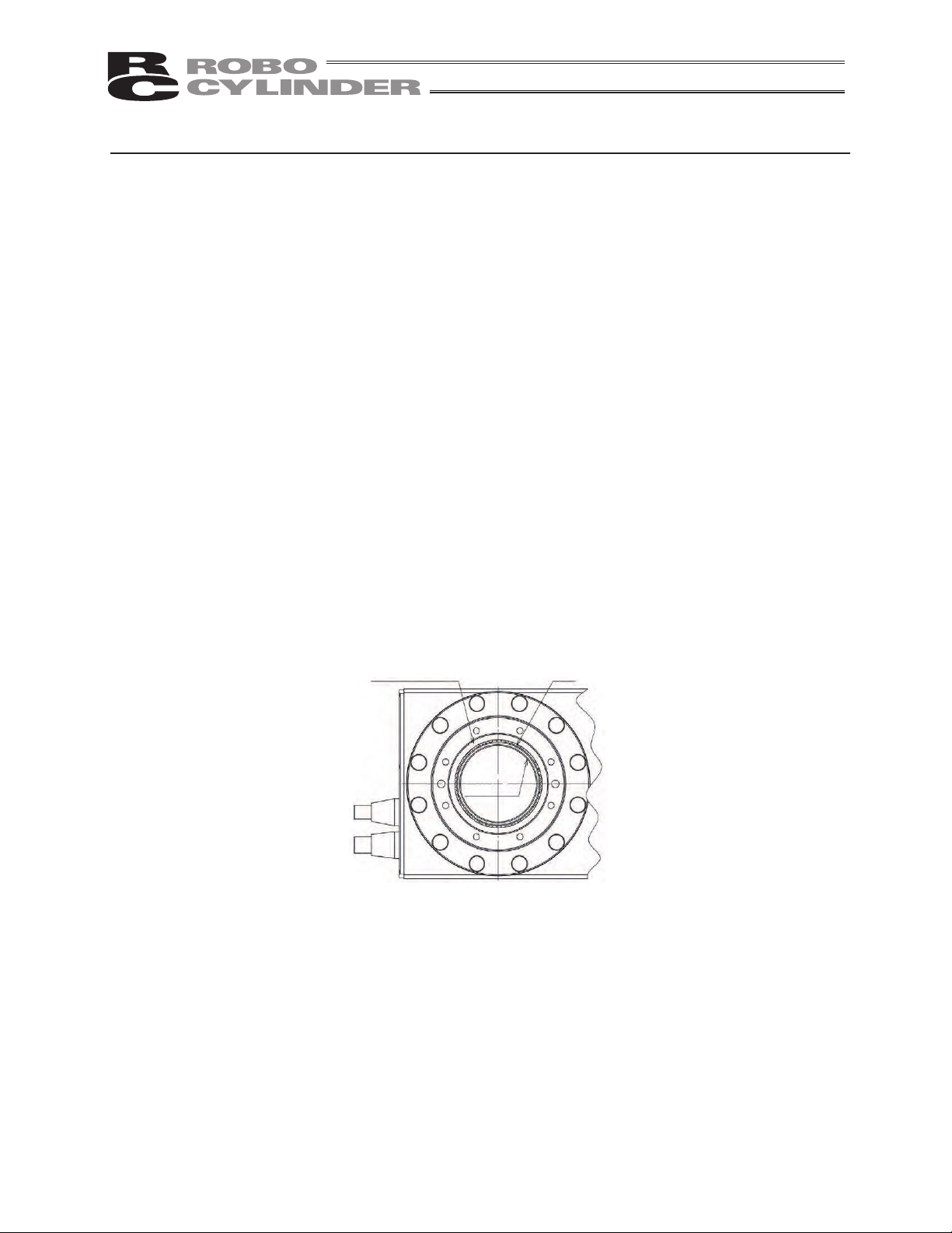
4. Do not let foreign matters enter between the output shaft (rotating part) and cylinder
(mounted part) of the hollow rotary actuator.
There is a gap of 1 mm between the output shaft (rotating part) and cylinder (mounted part) (see the figure
below), so do not let foreign matters, etc., enter this space. It may cause the actuator to fail.
Output shaft (rotating part)
Cylinder
(mounted part)
Gap
5. Do not let the cylinder of the hollow rotary actuator receive a large load.
The cylinder is made of a thin-walled pipe.
So that the cylinder will not receive a large load, design a tool to be installed on the output shaft or take
other appropriate measure.
8
Page 15

6. Whenever possible, use the RTC8L and RTC8HL types at speeds of 100 deg/s or
more.
If these actuators are operated at low speeds below 100 deg/s, the actuators will move slightly as they
move.
Even when the operating speed is low, however, vibration will decrease as the speed increases in the lowspeed range. Check the actual vibration level at the speeds you intend to use.
Take note that the larger the tool, the greater the vibration becomes at ends.
7. Transportation
7.1 Handling the Packed Actuator
When transporting the packed actuator, exercise due caution not to apply impact on the package by
dropping it or hitting it against other object.
x A person should never attempt to carry a heavy package on his own.
x When setting down the package temporarily, keep it horizontal.
x Do not step onto the package.
x Do not place on the package a heavy object that may deform the package or article of a shape that
allows the load to be concentrated in one area.
7.2 Handling the Unpacked Actuator
Once the actuator is unpacked, handle the actuator by its frame.
x When transporting the actuator, be careful not to hit it against other object. In particular, pay attention
to the output shaft and cover.
x Do not apply an excessive force to the various parts of the actuator. Pay special attention to the cables.
x When unpacking the actuator, exercise due caution not to drop the actuator. It may cause injury or
damage the machine.
x Should you find any part of the actuator missing or damaged during transportation, please contact an
IAI Sales Representative immediately.
9
Page 16

International Standards Compliances
This actuator complies with the following overseas standard.
Refer to Overseas Standard Compliance Manual (ME0287) for more detailed information.
RoHS Directive CE Marking
Optional
10
Page 17
Names of the Parts
The name of each part of the actuator is shown as follows.
1. Rotary
1.1 RT6
1.2 RT6R
Drive shaft
Frame
Motor encoder cable
Motor cover
Motor bracket Motor encoder cable
Motor cover
End cover
Flange
Drive shaft
Frame
Pulley cover
11
Page 18
1.3 RT7R
Motor encoder cable
Motor cover
FrameDrive shaft
Pulley cover
Flange
12
Page 19

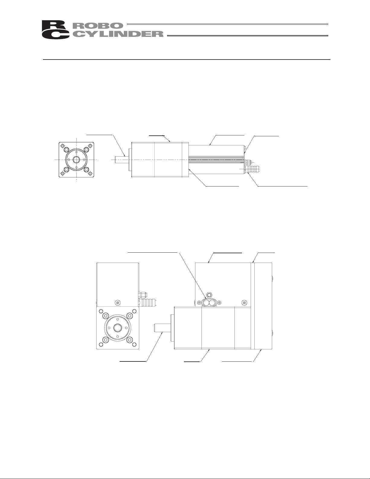
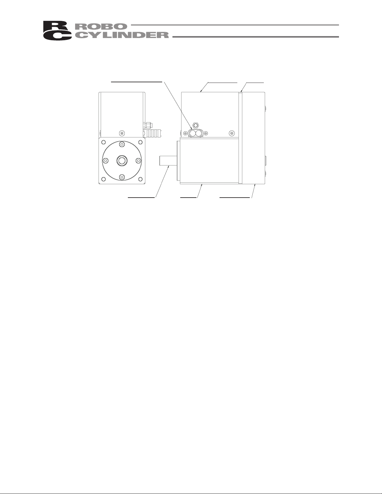
2. Hollow Rotary
Rear cover
Cylinder
Motor encoder cable
Output shaft
Front cover
Frame
13
Page 20

1. Checking the Product
This product, if of a standard configuration, consists of the items specified below.
Caution: Check the items included in the package by referring to the packing slip. Should you find
any item missing or bearing a wrong model number, please contact IAI or your IAI dealer.
1.1 Components
1. Checking the Product
No. Item Model number Remarks
1 Actuator
Accessories
2 Motor/encoder cables
3 Quick Step Guide
4 Operation Manual (CD)
5 Safety Guide
*1 The motor cable and encoder cable supplied with the actuator vary depending on the actuator
model and the controller used. [Refer to 9, “Motor/Encoder Cables.”]
1.2 Operation Manuals for Controllers Relating to This Product
(1) XSEL-J/K controllers
(Note) The hollow rotary actuators cannot be operated with XSEL-J/K controllers.
No. Name Control number
1 Operation Manual for XSEL-J/K Controller ME0116
2 Operation Manual for PC Software IA-101-X-MW/IA-101-X-USBMW ME0154
3 Operation Manual for Teaching Pendant SEL-T/TD/TG ME0183
Refer to “How to Read the Nameplate”
and “How to Read the Model Number.”
*1
14
4 Operation Manual for Teaching Pendant IA-T-X/XD ME0160
5 Operation Manual for DeviceNet ME0124
6 Operation Manual for CC-Link ME0123
7 Operation Manual for PROFIBUS ME0153
8 Operation Manual for X-SEL Ethernet ME0140
9 Operation Manual for Multi-point I/O Board ME0138
10 Operation Manual for Dedicated Multi-point I/O Board Terminal Block ME0139
Page 21

(2) XSEL-P/Q controllers
No. Name Control number
1 Operation Manual for XSEL-P/Q Controller ME0148
2 Operation Manual for XSEL-P/Q/PX/QX - RC Gateway Function ME0188
3 Operation Manual for PC Software IA-101-X-MW/IA-101-X-USBMW ME0154
4 Operation Manual for Teaching Pendant SEL-T/TD/TG ME0183
5 Operation Manual for Teaching Pendant IA-T-X/XD ME0160
6 Operation Manual for DeviceNet ME0124
7 Operation Manual for CC-Link ME0123
8 Operation Manual for PROFIBUS ME0153
(3) SSEL controllers
No. Name Control number
1 Operation Manual for SSEL Controller ME0157
2 Operation Manual for PC Software IA-101-X-MW/IA-101-X-USBMW ME0154
3 Operation Manual for Teaching Pendant SEL-T/TD/TG ME0183
4 Operation Manual for Teaching Pendant IA-T-X/XD ME0160
1. Checking the Product
5 Operation Manual for DeviceNet ME0124
6 Operation Manual for CC-Link ME0123
7 Operation Manual for PROFIBUS ME0153
(4) SCON controllers
No. Name Control number
1 Operation Manual for SCON Controller ME0161
2 Operation Manual for PC Software RCM-101-MW/RCM-101-USB ME0155
3 Operation Manual for Teaching Pendant CON-T/TG ME0178
4 Operation Manual for Teaching Pendant RCM-T/TD ME0173
5 Operation Manual for Simple Teaching Pendant RCM-E ME0174
6 Operation Manual for Data Setter RCM-P ME0175
7 Operation Manual for Touch Panel Display RCM-PM-01 ME0182
8 Operation Manual for DeviceNet ME0124
9 Operation Manual for CC-Link ME0123
10 Operation Manual for PROFIBUS ME0153
15
Page 22

1.3 How to Read the Nameplate
r
r
A
1.4 How to Read the Model Number
1. Checking the Product
<Series>
<Type>
RT6: Motor straight type
RT6R: Motor return type
RT7R: Motor return type with hollow shaft
RTC8L: Hollow, small, standard type
RTC8HL: Hollow, small, high-output type
RTC10L: Hollow, medium type
RTC12L: Hollow, large type
<Encoder type>
: Absolute
I: Incremental
Model numbe
Serial numbe
<Options>
L: Limit switch
(standard feature)
B: Brake
NM: Reversed-home specification
CE: CE Marking
<Cable length>
N: None
P: 1 m
S: 3 m
M: 5 m
X: Length specification
(Example:X07=7m)
R: Robot cable
(Example:R05=5m)
<Motor type>
12: Servo motor 12 W
20: Servo motor 20 W
60: Servo motor 60 W
150: Servo motor 150 W
16
<Applicable controllers>
T1: XSEL-J/K
T2: SCON
SSEL
XSEL-P/Q
<Oscillation angle>
300: 300 degrees
360: 360 degrees
<Deceleration ratio>
4: 1/4
15: 1/15
18: 1/18
24: 1/24
30: 1/30
*1
*1 The hollow rotary actuators cannot be operated
with XSEL-J/K controllers.
Page 23

2. Specifications
2.1 Rotary
RT6 RT6R RT7R
Deceleration ratio 1/18 1/4
Oscillation angle 300 deg
Maximum speed 500 deg/s
Rated acceleration 0.3 G
Rated Torque 2.4 N•m 0.764 N•m
Allowable inertial moment 2.5 × 10⁻² kg•m2 Max. 1.25 × 10⁻³ kg•m2 Max.
Driving System Ball Speed Reducer
Positioning Accuracy
Repeatability
Backlash 0.1 deg Max. 0.1 deg Max.
Allowable load moment/ 6.8 N•m Max. 8.9 N•m Max.
Thruster Load 100 N Max.
Encoder pulse count*1 16384 16384
*1 Number of pulses input to the controller.
Ball Speed Reducer +
Timing Belt
r0.02 mm
Timing Belt
2. Specifications
17
Page 24

2.2 Hollow Rotary
RTC8L RTC8HL
Deceleration ratio 1/24 1/15 1/24
Oscillation angle 0 to 359.99 deg 0 to 359.99 deg
Maximum speed 750 deg/s 1200 deg/s 750 deg/s
Acceleration 0.1 G to 0.3 G 0.1 G to 0.3 G
Output torque 0.55 N•m 0.53 N•m 0.85 N•m
2. Specifications
Allowable inertial moment 0.011 kg•m2 Max. 0.010 kg•m2 Max. 0.017 kg•m2 Max.
Driving System
Positioning Accuracy
Repeatability
Backlash
Allowable load moment/ 5 N•m 5 N•m
Thruster Load 400 N Max. 400 N Max.
Encoder pulse count*1 16384 16384
*1 Number of pulses input to the controller.
RTC10L RTC12L
Deceleration ratio 1/15 1/24 1/18 1/30
Oscillation angle 0 to 359.99 deg 0 to 359.99 deg
Maximum speed 1200 deg/s 750 deg/s 800 deg/s 600 deg/s
Acceleration 0.1 G to 0.3 G 0.1 G to 0.3 G
Output torque 1.7 N•m 2.8 N•m 5.2 N•m 8.6 N•m
Timing belt
+ Hypoid gear
r0.005 deg r0.005 deg
r0.05 deg Max. r0.05 deg Max.
Timing belt
+ Hypoid gear
Allowable inertial moment 0.033 kg•m2 Max. 0.054 kg•m2 Max. 0.10 kg•m2 Max. 0.17 kg•m2 Max.
Driving System
Positioning Accuracy
Repeatability
Backlash
Allowable load moment/ 10 N•m 25 N•m
Thruster Load 600 N Max. 800 N Max.
Encoder pulse count*1 16384 16384
*1 Number of pulses input to the controller.
18
Timing belt
+ Hypoid gear
r0.005 deg r0.005 deg
r0.05 deg Max. r0.05 deg Max.
Timing belt
+ Hypoid gear
Page 25

3. Installation Environment, Storage/Preservation Environment
3.1 Installation Environment
Install the actuator in an environment meeting the conditions listed below.
x not be exposed to direct sunlight.
x be free from irradiating heat coming from a heat treatment furnace or other equipment that generates a
large amount of heat.
x have surrounding air temperature of 0 to 40qC.
x have humidity of 85% or below (non-condensing).
x be free from corrosive or flammable gases.
x be free from excessive dust and suitable for normal assembly work.
x be free from oil mist or cutting oil.
x be free from impact or vibration.
x be free from strong electromagnetic field, ultraviolet light or radiation.
x Chemical resistance is not considered in the design of this product.
In general, the actuator should be used in an environment where the operators can work without wearing
any protective equipment or gear.
3.2 Storage Environment/Preservation
The storage/preservation environment conforms to the installation environment. If the robot is to be
stored/preserved for a prolonged period of time, be sure the robot will not be exposed to condensation.
Unless otherwise specified, desiccant is not placed in the carton when shipped. If the robot is to be
stored/preserved in an environment subject to condensation, provide preventive measures from over the
carton or directly to the robot after unpacking.
The maximum storage/preservation temperature is 60qC for a short storage period. If the robot is to be
stored/preserved for more than a month, the temperature should not exceed 50qC.
3. Installation Environment, Storage/Preservation Environment
19
Page 26

4. Installation
4.1 Rotary Type
4.1.1 Installing the Actuator
Utilize the tapped holes either on the front or on the bottom for installation.
Positions of the tapped holes are as shown in the following figures.
x RT6
4. Installation
4-M6 Depth 12
Caution: Never use long screws exceeding the maximum screw-in depth. Use of such long screws
may cause damage to the internal mechanisms and electrical parts.
20
Page 27

x RT6R
x RT7R
4. Installation
4-M6 Depth 12
9 through hole
4-M6 Depth 12
2-M8 Depth 12
Caution: Never use long screws exceeding the maximum screw-in depth. Use of such long screws
may cause damage to the internal mechanisms and electrical parts.
21
Page 28

4.2 Hollow Rotary
4.2.1 Installing the Actuator and a Tool on the Output Shaft
x The maximum screw-in depth varies depending on the mounting surface. Determine an appropriate
x Each mounting surface has circular holes and slotted holes for positioning pins. Use these holes as
(Note) The actuator has been shipped with setscrews put on the actuator mounting screws to prevent
4. Installation
[RTC8L, RTC8HL]
screw length by referring to the figure provided below.
Caution: Never use long screws exceeding the maximum screw-in depth. Use of such long screws
may cause damage to the internal mechanisms and electrical parts.
necessary.
entry of foreign matters.
Remove the setscrews when installing the actuator.
*
*
Depth 3.5
4-M5 Depth 10
+0.05
4 Depth 3.5
0
6-M4 Depth 6
+0.05
4 Depth 3.5
0
*
*
*
*
+0.010
2 -
4 H7 Depth 5
0
30 (Through)
+0.05
4 Depth 3.5
0
4-M5 Depth 10
*
*
4-M5 Depth 10
(Maximum screw-in depth: 9)
(Note) The dimension denoted by “*” is different between the RTC8L and RTC8HL .
+0.05
4 Depth 4
0
+0.05
4 Depth 4
0
22
Page 29

[RTC10L]
8-M4 Depth 6
+0.010
0
2-
4 H7 Depth 5
40 (Through)
+0.05
2-4 Depth 4 (Same on the opposite s ide)
0
8-M5 Depth 10
(Same on the opposite side)
+0.05
2-4 Depth 4
0
(Same on the opposite side)
+0.05
4 Depth 4
0
4-M5 Depth 10
+0.05
0
4 Depth 4
4. Installation
[RTC12L]
8-M5 Depth 8
54 (Through)
+0.05
2-5 Depth 4
0
(Same on the opposite side)
+0.012
5 H7 Depth 6
0
2-
+0.05
2-5 Depth 4 (Same on the opposite s ide)
0
8-M6 Depth 12
(Same on the opposite side)
+0.05
5 Depth 4
0
5 Depth 4
+0.05
0
4-M6 Depth 12
23
Page 30

Tightening torque
When mounting the tool or frame on the output shaft, do so according to the tightening torques listed
below.
Recommended tightening torque N•cm (kgf•cm)
Tapped hole diameter Bearing surface - Copper Bearing surface - Aluminum
M4 359 (36.7) 176 (18)
M5 727 (74.2) 342 (34.9)
M6 1234 (126) 536 (54.7)
* Hexagonal socket head bolt of strength category 10.9
4. Installation
Tightening screws
x Use high-tension bolts of ISO-10.9 or higher.
x If tapped holes are used, make sure the screws are not longer than the fitting length.
x Make sure the effective fitting length between the bolt and tapped hole used for installing the actuator
is at least one of the following values, whichever is applicable:
x When the material of the tapped through hole is steel: Same as the nominal diameter
x When the material of the tapped through hole is aluminum: Twice the nominal diameter
24
Page 31

4.2.2 Installation Direction and Mounting Surface
Install the actuator using the mounting surface corresponding to the load direction.
(1) Installing horizontally
Load direction
Installation surface
(2) Installing on side
4. Installation
Installation surface
(3) Even when the actuator is installed on its side, follow this installation layout if a large load will apply in
the direction shown in the figure below:
Installation surface
Load direction
Load direction
25
Page 32

4.2.3 Load Offset Distance
Vibration tends to increases as the center of gravity of the work part becomes farther away from the center
of the rotational axis. Design an appropriate tool by using the table as a guide.
4. Installation
Model Offset distance [m]
RTC8L 0.10
RTC8HL 0.12
RTC10L 0.15
RTC12L 0.20
26
Page 33

5. Connecting to the Controller
The following explains the wiring method by assuming use of a single axis.
5.1 Wiring
The actuator and controller are connected by the motor cable and encoder cable (genuine part) via
connectors.
Motor cable Controller
Actuator
Encoder cable
Example of Connection with XSEL Controller
[For details on the relay cables, refer to 9, “Motor/Encoder Cables.”]
Caution: x In applications where the cables cannot be secured, keep the bending radius of each
cable within the range of cable deflection by the weight of the cable itself, or use a selfstanding cable hose or take other measure to keep the bending radius sufficiently large,
so as to minimize the load received by the cables.
x Do not cut and extend or shorten the cables or reconnect the cut cable.
x Do not pull or forcibly bend the cables, as the lead wires may break.
5. Connecting to the Controller
27
Page 34

When designing an application system using actuators and controllers, incorrect wiring or connection of
each cable may cause unexpected problems such as a disconnected cable or poor contact. This section
explains prohibited handling of cables. Read the information carefully to connect the cables properly.
x Do not let the cable flex at a single point.
x Do not let the cable bend, kink or twist.
5. Connecting to the Controller
x Do not let the cable receive a turning force at
a single point.
Steel band
(piano wire)
Bundle loosely.
x Do not pull the cable with a strong force.
x When fixing the cable, provide a moderate
slack and do not tension it too tight.
Use a curly
cable.
x Do not pinch, drop a heavy object onto or cut
the cable.
Do not use a spiral tube
where the cable flexes
frequently.
28
Page 35

z Cautions for use of a cable track
z The actuator cable is not a robot cable, so never
store the actuator cable in a cable track.
Bending radius r
z For the motor and encoder
cables, always use robot
cables.
z The bending radius of the cable track must not exceed the minimum
bending radius of the cables. [Refer to 9, “Motor/Encoder Cables.”]
z Do not let the cable get tangled or kinked in a cable track or flexible tube. When bundling the cable, keep a certain
degree of flexibility (so that the cable will not become too taut when bent).
5. Connecting to the Controller
z Do not cause the cables to occupy more than 60% of
the space in the cable track.
Cable track
Cable
z Do not lay signal lines together with circuit lines that
create a strong electric field.
Power line
Duct
Signal lines
(flat cable)
29
Page 36

6. Notes on Operation
6.1 Rotary
6.1.1 Backlash and Positioning Accuracy Repeatability
The rotary actuator has backlash (play). If the movement is smaller than the backlash, there may be a
possibility that the drive shaft does not rotate.
In the case the equipment operates in only one way, it is able to position within the range of the
positioning accuracy repeatability unless the gears in the decelerator get free, however, it may move
within the range of the backlash while it is stopped, and which may cause variance in the position.
Also, when the operation direction is changed, the drive amount may be shortened due to the backlash. In
such a case, input the position including the drive amount and the backlash amount.
Backlash (Play) and Positioning Accuracy Repeatability
Model Backlash (Play) Positioning Accuracy Repeatability
RT6
RT6R
RT7R 0.5 deg Max.
6. Notes on Operation
6.1.2 Operation Range and Home Return
(1) Range of Operation
The operation range of the rotary equipment is 300 degrees clockwise in the direction of the shaft
rotation.
There is no mechanical stopper, thus the equipment may exceed the operation range if it is rotated
manually by hand while the servo is off. Please note that it may return to the home position in the
opposite direction if it is out of the operation range. Refer to (2), "Home Return.")
Please use the marking sticker included in the package as the reference of the operation range.
Note) For RT7R, the position data will be displayed as "299.99" even if putting in "300". This is due
0.1 deg Max.
to the encoder resolution, and the actual position will also be "299.99".
r0.02 deg
r0.1 deg
30
Page 37

(2) Home return
When performing a home-return operation to the rotary, the rotary direction to home-return differs as
shown in the figures below due to the position where the shaft is when the home-return operation
starts.
1) If the shaft does not detect the sensor at the home-return start, it moves counterclockwise in the
view of the shaft tip ([1]), and it reverses if sensor is detected ([2]), and then stops when the Zphase is detected. (Refer to Figure 1.)
Sensor detection range
Home
Shaft
[2]
C
Sensor sensitive device
[1]
Operation range (300 degrees)
Figure 1
2) If the shaft detects the sensor at the home-return start (when the shaft is rotated over 300
degrees by hand at the servo off), it rotates clockwise from the stopped position ([3]), and stops
when the Z-phase is detected. (Refer to Figure 2.)
Sensor detection range
Sensor sensitive device
Home
Shaft
[3]
6. Notes on Operation
Operation range (300 degrees)
Figure 2
Operation range of the rotary is generally 300 degrees. However, in some cases it rotates 360
degrees as stated above.
Be careful of interference of the rotary to its surroundings.
31
Page 38

6.1.3 Conditions for Loads Installable to Shaft of Rotary
There is a limitation for the objects that are available to attach on the shaft of the rotary determined by its
limit ranges of the allowable load moment, rated torque and allowable moment of inertia.
Please note that a use of the product in a condition beyond the limit range may shorten the product’s life
or cause malfunction.
The table below shows the allowable load moment, rated torque and allowable moment of inertia for each
model. Also, shown in the figure below tells how to consider the load moment.
Conditions of Attachable Things to Shaft
Model
RT6
RT6R
RT7R 8.9 (0.907) 0.764 (0.078) 1.25 × 10⁻³ (0.012)
6. Notes on Operation
Allowable load moment
Nm (kgfm)
Rated Torque
Nm (kgfm)
6.8 (0.694) 2.4 (0.25) 2.5 × 10
Load
Allowable Moment of Inertia
kgm
2
(gfcms2)
-2
(0.25)
32
Datum for load moment
Load moment distance
Page 39

6.2 Hollow Rotary
6.2.1 Operation Range and Home Return
(1) Range of Operation
z Rotational axis/Normal mode
In the absolute position specification mode, the actuator operates in the range shown below.
The maximum range of rotation varies depending on the deceleration ratio.
Deceleration ratio Maximum range of rotation
15 0 to 9999.99
18 0 to 9999.99
24 0 to 7670.99
30 0 to 6140.99
z Rotational axis/Index mode
In the absolute position specification mode, the actuator operates in the range of 0 to 359.99
degrees.
* Refer to the controller specification for details.
(2) Home return
The actuator operates as follows during a home return or upon an absolute reset:
[1] Start of home return o [2] Detection of home sensor signal o [3] Search for Z-phase, reversing o
[4] Detection of home sensor signal o [5] Movement by offset distance o [6] Home position
[1]
Range of home return T
x RTC8L, RTC8HL: 18 degrees
[5]
[4]
[6]
[2]
[3]
x RTC10L, RTC12L: 15 degrees
Rotational
axis
Home
(end of forward rotation)
Offset movement distance
Home sensor position
6. Notes on Operation
Range of Z-phase search
Caution: The actuator always rotates in the same direction during a home return.
If the actuator is of a standard specification, it always performs a home return in the
counterclockwise direction from any position outside the range of Z-phase search shown
in the figure. The actuator does not take a shortcut.
If a cable is passed through the opening, pay attention to the load on the cable. An
excessive load may sever its lead wires.
33
Page 40

6.2.2 Brake
x The actuator’s brake is designed to hold the work part in place. Do not use it to decelerate the actuator
or actuate an emergency stop.
x To release the brake manually, use the brake switch on the controller.
(Note) If the actuator must hold the work part in place, check the holding torque.
6. Notes on Operation
34
Page 41

7. How to Select a Hollow Rotary Actuator Model
Select an appropriate model based on the shape and mass of the work part on the output shaft, by
referring to the figure and graphs shown below.
(1) Disk-shaped work part at the center of the output shaft
J = M•r2/2
(Radius of disk)
Disk-shaped work part on RTC8 Disk-shaped work part on RTC10L
7. How to Select a Hollow Rotary Actuator Model
Mass of disk [kg]
Radius of disk [cm]
Disk-shaped work part on RTC12L
Mass of disk [kg]
Radius of disk [cm]
Mass of disk [kg]
Radius of disk [cm]
35
Page 42

(2) Work part offset from the center of the output shaft
J = M•r2
(Offset distance)
7. How to Select a Hollow Rotary Actuator Model
Offset work part
Mass of work part [kg]
Offset distance [cm]
Offset work part
Offset work part
Mass of work part [kg]
Offset distance [cm]
* When the rotational axis is used horizontally, a load
torque will generate due to the gravitational
acceleration if the work part is installed at a position
offset from the center of rotation. In this case, you
must lower the rotational speed or reduce the mass of
the work part.
36
Mass of work part [kg]
Offset distance [cm]
Page 43

8. Options
8.1 Limit Switch
Normally during the home return operation, the slider contacts the stopper and reverses, and then detect
Z-phase (“push method”). The home limit switch (L) is used to cause the actuator to reverse not upon
contact, but using a proximity sensor.
The limit switch is a standard feature on both the rotary type and hollow rotary type.
8.2 Brake
The brake is a mechanism to hold the work part and thereby prevent it from dropping and sustaining
damage when the power or servo is turned off on the actuator installed on its side.
This brake is designed to hold the work part in place. Do not use it to decelerate the actuator or actuate an
emergency stop.
The model name for the brake is “B.”
8.3 Reversed-home Specification
If the reversed-home specification is selected, the actuator rotates in the counterclockwise direction, which
is opposite the direction in which the standard specification actuator would rotate, as the actuator moves
to a + position. Also during a home return, the actuator rotates in the opposite direction compared to the
standard specification. The model name for the reversed-home specification is “NM.”
8. Options
37
Page 44

9. Motor/Encoder Cables
All cables apply commonly regardless of the actuator model name. The applicable cables vary depending
on the connected controller.
Correspondence table of controllers and motor/encoder cables
XSEL-J/K XSEL-P/Q, SSEL, SCON
Applicable cables [1], [2], [3] [1], [4]
[1] Motor cable CB-X-MA***
* *** indicates the cable length (L). Up to 30 m can be specified.
Example) 080 = 8 m
[Minimum bending radius]
(Front view)
Controller e nd
[2] Encoder cable CB-X-PA***
Actuator e nd
(Front view)
Moving cable: 51 mm
Mounted cable: 34 mm
Wire Color Signal
Green
Red
White
Black
Signal Color Wire
Green
Red
White
Black
9. Motor/Encoder Cables
(Front view)
Controller e nd
Actuator e nd
(Front view)
* *** indicates the cable length (L). Up to 30 m can be specified.
Example) 080 = 8 m
[Minimum bending radius]
Moving cable: 44 mm
Mounted cable: 29 mm
Wire Color Signal
Blue
Orange
(Crimped)
Black
Yellow
Green
Brown
Gray
Red
Connect the shield to the hood with a clamp.
Ground and braided shield wires
Signal Color Wire
Black
Yellow
Blue
Orange
Green
Brown
Ground
Gray
Red
(Crimped)
38
Page 45

[3] Limit switch cable CB-X-LC***
(Front view)
Controller e nd
[4] Encoder cable with LS CB-X2-PLA***
Controller e nd
Actuator e nd
LS end
Actuator e nd
(Front view)
Wire Color Signal
Wire Color Signal
(Front view)
* *** indicates the cable length (L). Up to 30 m can be specified.
Example) 080 = 8 m
[Minimum bending radius]
Moving cable: 33 mm
Mounted cable: 22 mm
Signal Color Wire
Light blue
Pink
Light green
Orange
Gray
1B/
Light blue
Light blue
Light green
Orange
Gray
Light blue
Note) “1B” indicates one black dot.
* *** indicates the cable length (L). Up to 30 m can be specified.
Example) 080 = 8 m
[Minimum bending radius]
Moving cable: 58 mm
Mounted cable: 38 mm
White/
Orange
White/
Green
Brown/
Blue
Brown/
Yellow
Brown/
Red
Brown/
Black
White/
Blue
White/
Yellow
White/
Red
(Soldered)
White/
Black
White/
Purple
White/
Gray
Orange
Green
Purple
Gray
Red
Black
Blue
Yellow
Connect the shield to the hood with a clamp.
Ground and braided shield wires
(“White/blue” in the wire color fiel d indicates
a white band with a blue insulator band.)
Signal Color Wire
White/
Orange
White/
Green
Brown/
Blue
Brown/
Yellow
Brown/
Brown/
Black
Signal Color Wire
White/
White/
Yellow
White/
White/
Black
White/
Purple
White/
Ground
Orange
Green
Purple
Gray
Red
Black
Blue
Yellow
Pink
1B/
9. Motor/Encoder Cables
(Crimped)
Red
Blue
Red
Gray
(Crimped)
39
Page 46

10. Maintenance/Inspection
Daily and periodic inspections are essential to making sure your actuator will operate safely and efficiently.
Before carrying out each inspection, check the applicable maintenance/inspection items listed below.
10.1 Inspection Items and Schedule
Conduct visual inspection and add grease at the applicable schedules specified below.
The following schedule is based on eight hours of operation daily. If the actuator is operated at a higher
utilization rate, including when it is operated continuously day and night, shorten the inspection intervals
as necessary.
At startup inspection
1 month after start of operation
6 months after start of operation
1 year after start of operation
Every 6 months thereafter
Every year thereafter
* Any adjustments requiring the following operations must be carried out at our factory. Do not
disassemble the actuator or cut any of its cables in the location where the actuator is installed.
x Disassemble the motor
x Disassemble the gear
x Disassemble the bearing
x Cut a cable
If the user has disassembled any of the above components or cut any of the actuator’s cables, IAI will
10. Maintenance/Inspection
not be responsible for any malfunction or problem that may occur thereafter.
Visual inspection
{
{
{
{{
{
{{
Greasing of hollow
rotary actuator
Warning: x Performing inspection or maintenance work without a thorough understanding of the
specific tasks involved may result in a serial accident.
x If inspection is not carried out regularly, the drive part may reach its life prematurely or
the actuator may suddenly start malfunctioning.
40
Page 47

10.2 Visual Inspection of the Exterior
In the visual inspection of the exterior, check the following items.
Actuator Loosening of actuator mounting bolts, etc.
Cables Scratches, proper connection of connectors
Overall Noise, vibration
x With the hollow rotary type, grease that has been applied to the gears may drip depending on
the environment. Clean the areas dirtied by grease or add grease, as necessary.
10.3 Exterior Cleaning
x Clean the exterior of the actuator as necessary.
x Use a soft cloth, etc., to wipe off dirt.
x Do not blow compressed air onto the actuator too strongly, in order to prevent dust from entering the
actuator through small openings and gaps.
x Do not use petroleum solvent as it may damage the resin parts and coated surfaces.
x To clean stubborn soiling, moisten a soft cloth, etc., with neutral detergent and wipe gently.
10.4 Adding Grease to the Hollow Rotary Gears
On the hollow rotary actuators (RTC8L, RTC8HL, RTC10L, RTC12L), add grease to the gears periodically
according to the periodic inspection intervals.
(1) Applicable grease
The actuators have been charged with the following gear grease prior to shipment from IAI.
Kyodo Yushi AC-D No.2
During the maintenance, use lithium grease No. 2. Corresponding products include those listed below.
Showa Shell Sekiyu Albania Grease No. 2
Mobil Sekiyu Mobilux 2
10. Maintenance/Inspection
41
Page 48

(2) How to add grease
[1] Remove the screws mounting the rear cover (countersunk machine screw M2.6 x 6).
Pull the rear cover slightly from the actuator frame. (Do not forcibly pull the cables inside.)
Round terminal
[2] While turning the gears, apply grease from the rear opening just enough to coat the bottom of the
teeth. (As the input shaft is turned, the output gears turn.)
Thereafter, turn the grease several times in both directions to let the grease spread evenly.
10. Maintenance/Inspection
You should see the gears through
this opening.
Apply grease on the tooth surface.
42
Turn.
If the actuator has a brake,
connect the controller to
release the brake.
Page 49

[3] Install and mount the front cover and rear cover.
Be careful not to pinch the cables when mounting the rear cover.
Warning: x Never use fluorine grease. If fluorine grease is mixed with lithium grease, grease
function will drop and the mechanical parts will be damaged.
x Do not add grease any more than necessary. Excess grease may flow to the electronic
components and cause malfunction.
x The encoder phase has been adjusted precisely for detection of rotational angles and
home signals. Never touch the encoder, as it may lead to a failure.
x Be careful not to pinch the cables when affixing the rear cover. Store the cables neatly
in the space above without them resting on top of one another. Do not forcibly tighten
the screws when the panel is not fully seated.
10. Maintenance/Inspection
43
Page 50

11. External Dimensions
11.1 Rotary
x RT6
4-M6 Depth 12
11. External Dimensions
* For the connection to motor cable,
encoder cable and limit switch cable
44
40 Min.
Secure
Cable Joint
Connectors *1
Weight [kg] 1.9
Page 51

x RT6R
4-M6 Depth 12
Cable Joint
Connectors *1
11. External Dimensions
Secure 40 Min.
* For the connection to motor cable,
encoder cable and limit switch cable
Weight [kg] 2.8
45
Page 52

x RT7R
4-M6 Depth 12
2-M8 Depth 12
9 through
hole
11. External Dimensions
Cable Joint
Connectors *1
Secure 40 Min.
* For the connection to motor cable,
encoder cable and limit switch cable
46
Weight [kg] 2.6
Page 53

11.2 Hollow Rotary
x RTC8L, RTC8HL
4 Depth 3.5
+0.05
0
*
*
0
4-M5 Depth 10
4-M5 Depth 10
6-M4 Depth 6
4 Depth 3.5
+0.05
0
Depth 3.5
*
*
*
*
30 (Through)
4 Depth 3.5
+0.05
2 - 4 H7 Depth 5
(Note) The dimension denoted by “*” is different
between the RTC8L and RTC8HL .
4 Depth 4
0
+0.05
(Maximum screw-in depth: 9)
4-M5 Depth 10
+0.010
0
11. External Dimensions
*
*
4 Depth 4
+0.05
0
Weight [kg]
RTC8L 2.3
RTC8HL 2.4
47
Page 54

x RTC10L
8-M4 Depth 6
2-4 Depth 4 (Same on the opposite side)
+0.05
0
40 (Through)
2-4 Depth 4 (Same on the opposite side)
+0.05
0
8-M5 Depth 10 (Same on the opposite side)
2-4 H7 Depth 5
11. External Dimensions
+0.010
0
4 Depth 4
+0.05
0
4 Depth 4
+0.05
0
4-M5 Depth 10
48
Weight [kg] 3.5
Page 55

x RTC12L
8-M5 Depth 8
54 (Through)
2-5 Depth 4 (Same on the opposite side)
+0.05
0
2-5 Depth 4 (Same on the opposite side)
+0.05
0
8-M6 Depth 12 (Same on the opposite side)
2-5 H7 Depth 6
+0.012
0
11. External Dimensions
5 Depth 4
+0.05
0
5 Depth 4
+0.05
0
4-M6 Depth 12
Weight [kg] 6.5
49
Page 56

12. Warranty
12.1 Warranty Period
One of the following periods, whichever is shorter:
x 18 months after shipment from IAI
x 12 months after delivery to the specified location
x 2,500 hours of operation
12.2 Scope of Warranty
Our products are covered by warranty when all of the following conditions are met. Faulty products
covered by warranty will be replaced or repaired free of charge:
(1) The breakdown or problem in question pertains to our product as delivered by us or our authorized
dealer.
(2) The breakdown or problem in question occurred during the warranty period.
(3) The breakdown or problem in question occurred while the product was in use for an appropriate
purpose under the conditions and environment of use specified in the operation manual and catalog.
(4) The breakdown or problem in question was caused by a specification defect or problem, or by the
poor quality of our product.
Note that breakdowns due to any of the following reasons are excluded from the scope of warranty:
[1] Anything other than our product
[2] Modification or repair performed by a party other than us (unless we have approved such
modification or repair)
[3] Anything that could not be easily predicted with the level of science and technology available at
the time of shipment from our company
[4] A natural disaster, man-made disaster, incident or accident for which we are not liable
[5] Natural fading of paint or other symptoms of aging
[6] Wear, depletion or other expected result of use
[7] Operation noise, vibration or other subjective sensation not affecting function or maintenance
12. Warranty
Note that the warranty only covers our product as delivered and that any secondary loss arising from a
breakdown of our product is excluded from the scope of warranty.
12.3 Honoring Warranty
As a rule, the product must be brought to us for repair under warranty.
12.4 Limited Liability
[1] We shall assume no liability for any special damage, consequential loss or passive loss such as a
loss of expected profit arising from or in connection with our product.
[2] We shall not be liable for any program or control method created by the customer to operate our
product or for the result of such program or control method.
50
Page 57

12.5 Conditions of Conformance with Applicable Standards/Regulations, Etc., and Applications
(1) If our product is combined with another product or any system, device, etc., used by the customer, the
customer must first check the applicable standards, regulations and/or rules. The customer is also
responsible for confirming that such combination with our product conforms to the applicable
standards, etc. In such a case we will not be liable for the conformance of our product with the
applicable standards, etc.
(2) Our product is for general industrial use. It is not intended or designed for the applications specified
below, which require a high level of safety. Accordingly, as a rule our product cannot be used in these
applications. Contact us if you must use our product for any of these applications:
[1] Medical equipment pertaining to maintenance or management of human life or health
[2] A mechanism or mechanical equipment intended to move or transport people (such as a vehicle,
railway facility or aviation facility)
[3] Important safety parts of mechanical equipment (such as safety devices)
[4] Equipment used to handle cultural assets, art or other irreplaceable items
(3) Contact us at the earliest opportunity if our product is to be used in any condition or environment that
differs from what is specified in the catalog or operation manual.
12.6 Other Items Excluded from Warranty
The price of the product delivered to you does not include expenses associated with programming, the
dispatch of engineers, etc. Accordingly, a separate fee will be charged in the following cases even during
the warranty period:
[1] Guidance for installation/adjustment and witnessing of test operation
[2] Maintenance and inspection
[3] Technical guidance and education on operating/wiring methods, etc.
[4] Technical guidance and education on programming and other items related to programs
12. Warranty
51
Page 58

Change History
noisiveRfonoitpircseDetaDnoisiveR
August 2010 Second Edition P. 8 Added “Handling Precautions.”
”tcudorPehtgnikcehC“,1deddA51ot31.P
”.snoitpO“,9deddA63.P
”.selbaCredocnE/rotoM“,01deddA83ot73.P
June 2011 Third Edition P. 9 Added a “note on speeds of RTC8L and RTC8HL types.”
g“tahtnoitamrofnideddA04.P rease may drip” in 10.2, “Visual
Inspection of the Exterior.”
P. 49 to 50 Contents changed in 12. Warranty
Forth EditionSeptember 2012
P.1 to P.7 Additions and Changes made in Safety Guide contents
P.10 International Standards Compliances added
P.16 CE: Complied with CE Mark added to “How to Read
Model Code” option
P.44 to 49 Weight added to “11. External Dimensions”
”.traPhcaEfoemaN“ni”rotautcAyratoRwolloH“deddA21.P
”.noitacificepS“,2ni”rotautcAyratoRwolloH“deddA71.P
”.noitallatsnI“,5ni”rotautcAyratoRwolloH“deddA22ot12.P
”.noitarepOnosetoN“,7ni”rotautcAyratoRwolloH“deddA33ot23.P
”.ledoMrotautcAyratoRwolloHatceleSotwoH“,8deddA53ot43.P
”.noisnemiDlanretxE“,21ni”rotautcAyratoRwolloH“deddA84ot64.P
Change History
52
Page 59

Page 60

Catalog No.: ME3658-4A
Head Office: 2690 W. 237th Street, Torrance, CA 90505
TEL (310) 891-6015 FAX (310) 891-0815
Chicago Office: 1261 Hamilton Parkway, Itasca, IL 60143
TEL (630) 467-9900 FAX (630) 467-9912
Atlanta Office: 1220 Kennestone Circle, Suite 108, Marietta, GA 30066
TEL (678) 354-9470 FAX (678) 354-9471
website: www.intelligentactuator.com
Ober der Röth 4, D-65824 Schwalbach am Taunus, Germany
TEL 06196-88950 FAX 06196-889524
IAI (Shanghai) Co., Ltd.
SHANGHAI JIAHUA BUSINESS CENTER A8-303, 808, Hongqiao Rd. Shanghai 200030, China
TEL 021+6448-4753 FAX 021-6448-3992
website: www.iai-robot.com
The information contained in this document is subject to change without notice for the purpose of product improvement.
Copyright ¢ 2012. Sep. IAI Corporation. All rights reserved.
 Loading...