

Page 1

ROBO Cylinder
�
Arm Type
RCA RCS2 Actuators
Operation Manual
Sixth Edition
�
�
Arm Type: RCA Type: A4R, A5R, A6R
RCS2 Type: A4R, A5R, A6R
�
IAI America, Inc.
Page 2

Page 3

Please Read Before Use
Thank you for purchasing our product.
This Operation Manual describes all necessary information to operate this product safely such as the
operation procedure, structure and maintenance procedure.
Before operation, read this manual carefully and fully understand it to operate this product safely.
The DVD that comes with the product contains operation manuals for IAI products.
For a use of the products, print out or display on your personal computer the necessary pages of the
applicable Instruction Manuals.
After reading the Operation Manuals, be sure to keep them in a convenient place easily accessible to
the personnel using this product.
[Important]
� This Operation Manual is original.
� This product is not to be used for any other purpose from what is noted in this Operation Manual.
IAI shall not be liable whatsoever for any loss or damage arising from the result of using the
product for any other purpose from what is noted in the manual.
� The information contained in this Operation Manual is subject to change without notice for the
purpose of production improvement.
� If you have any question or finding regarding the information contained in this Operation Manual,
contact our customer center or our sales office near you.
� Using or copying all or a part of this Operation Manual without permission is prohibited.
� The company names, names of products and trademarks of each company shown in the
sentences are registered trademarks.
Page 4

Page 5

Table of Contents
Safety Guide ·················································································································· 1
Caution in Handling ·········································································································· 8
International Standards Compliances··············································································· 9
Names of the Parts········································································································· 10
1. Specifications Check······················································································· 11
1.1 Checking the Product ························································································ 11
1.1.1 Parts ··············································································································· 11
1.1.2 Operation Manuals for the Controllers Related to this Product ······················ 11
1.1.3 How to Read the Model Nameplate ·······························································13
1.1.4 How to Read the Model Number ···································································· 14
1.2 Specification ······································································································15
1.2.1 Speed ············································································································· 15
1.2.2 Maximum Acceleration and Transportable Weight ·········································15
1.2.3 Driving System • Position Detector································································· 16
1.2.4 Positioning Repeatability ················································································16
1.2.5 Lost Motion·····································································································16
1.2.6 Allowable Load Moments of the Actuator ·······················································17
1.3 Options··············································································································18
1.3.1 Brake Type (Model: B)···················································································· 18
1.3.2 Low Power Consumption Type (Model: LA) ··················································· 18
1.3.3 Reversed-home Type (Model:
NM) ······························································· 18
1.3.4 Motor Reversed Directions (Model: NM, ML, MR) ·········································18
1.3.5 CE Mark Complied (Model: CE) ····································································· 18
1.4 Motor • Encoder Cables ···················································································· 19
1.4.1 Motor • Encoder Integrated Cables for the RCA Actuator ······························19
[1]
Motor Cable Model : CB-ACS-MA��······························································19
[2]
Encoder Cable • Encoder Robot Cable
Model : CB-ACS-PA��� • CB-ACS-PA���-RB············································· 20
[3]
Motor • Encoder Integrated Cables for AMEC/ASEP
Model : CB-ASEP-MPA��� ·········································································21
1.4.2 Motor • Encoder Integrated Cables for the RCS2 Actuator ····························22
[1]
Motor Cable • Motor Robot Cable
Model : CB-RCC-MA��� • CB-RCC-MA���-RB ··········································22
[2] Encoder Cable • Encoder Robot Cable
[For SCON, SSEL, XSEL-P/Q]
Model : CB-RCS2-PA��� • CB-RCS2-PA���-RB ········································23
[3] Encoder Cable • Encoder Robot Cable [For XSEL-J/K]
Model : CB-RCBC-PA��� • CB-RCBC-PA���-RB·······································24
Page 6

2. Installation······································································································· 25
2.1 Transportation ··································································································· 25
2.2 Installation and Storage • Preservation Environment ········································ 27
2.3 How to Install ·····································································································28
2.3.1 General Rules on Installation ·········································································28
2.3.2 Installation of the Main Unit ············································································ 29
2.3.3 Mounting Surface ···························································································30
2.3.4 Attachment of the Transported Object···························································· 31
3. Connecting with the Controller········································································ 32
4. Maintenance Inspection·················································································· 38
4.1 Inspection Items and Schedule ········································································· 38
4.2 External Visual Inspection ·················································································38
4.3 Cleaning ············································································································ 38
4.4 Interior Inspection ······························································································39
4.5 Internal Cleaning ······························································································· 40
4.6 Grease supply ··································································································· 40
4.6.1 Applicable greases ························································································· 40
4.6.2 How to Apply Grease······················································································41
4.7 Reduction Belt·······································································································42
4.7.1 Inspection of the Belt······················································································ 42
4.7.2 Applicable Belt································································································42
4.7.3 Adjusting the Belt Tension ·············································································· 43
4.7.4 Replacing the Motor of the Motor Reversing Type ········································· 44
4.8 Replacing the Motor ·························································································· 49
5. External Dimensions······················································································· 55
5.1 RCA-A4R··········································································································· 55
5.2 RCA-A5R··········································································································· 56
5.3 RCA-A6R··········································································································· 57
5.4 RCS2-A4R········································································································· 58
5.5 RCS2-A5R········································································································· 59
5.6 RCS2-A6R········································································································· 60
6. Life·················································································································· 61
7. Warranty ········································································································· 62
7.1 Warranty Period ······························································································· 62
7.2 Scope of the Warranty······················································································· 62
7.3 Honoring the Warranty ······················································································ 62
7.4 Limited Liability ··································································································62
7.5 Conditions of Conformance with Applicable Standards/Regulations,
Etc., and Applications ························································································63
7.6 Other Items Excluded from Warranty ································································63
Change History·················································································································· 64
Page 7

1
Safety Guide
“Safety Guide” has been written to use the machine safely and so prevent personal injury or property
damage beforehand. Make sure to read it before the operation of this product.
Safety Precautions for Our Products
The common safety precautions for the use of any of our robots in each operation.
No.
Operation
Description
Description
1 Model
Selection
� This product has not been planned and designed for the application where
high level of safety is required, so the guarantee of the protection of human
life is impossible. Accordingly, do not use it in any of the following
applications.
1) Medical equipment used to maintain, control or otherwise affect human
life or physical health.
2) Mechanisms and machinery designed for the purpose of moving or
transporting people (For vehicle, railway facility or air navigation facility)
3) Important safety parts of machinery (Safety device, etc.)
� Do not use the product outside the specifications. Failure to do so may
considerably shorten the life of the product.
� Do not use it in any of the following environments.
1) Location where there is any inflammable gas, inflammable object or
explosive
2) Place with potential exposure to radiation
3) Location with the ambient temperature or relative humidity exceeding
the specification range
4) Location where radiant heat is added from direct sunlight or other large
heat source
5) Location where condensation occurs due to abrupt temperature
changes
6) Location where there is any corrosive gas (sulfuric acid or hydrochloric
acid)
7) Location exposed to significant amount of dust, salt or iron powder
8) Location subject to direct vibration or impact
� For an actuator used in vertical orientation, select a model which is
equipped with a brake. If selecting a model with no brake, the moving part
may drop when the power is turned OFF and may cause an accident such
as an injury or damage on the work piece.
Page 8

2
No.
Operation
Description
Description
2 Transportation � When carrying a heavy object, do the work with two or more persons or
utilize equipment such as crane.
� When the work is carried out with 2 or more persons, make it clear who is
to be the leader and who to be the follower(s) and communicate well with
each other to ensure the safety of the workers.
� When in transportation, consider well about the positions to hold, weight
and weight balance and pay special attention to the carried object so it
would not get hit or dropped.
� Transport it using an appropriate transportation measure.
The actuators available for transportation with a crane have eyebolts
attached or there are tapped holes to attach bolts. Follow the instructions
in the operation manual for each model.
� Do not step or sit on the package.
� Do not put any heavy thing that can deform the package, on it.
� When using a crane capable of 1t or more of weight, have an operator who
has qualifications for crane operation and sling work.
� When using a crane or equivalent equipments, make sure not to hang a
load that weighs more than the equipment’s capability limit.
� Use a hook that is suitable for the load. Consider the safety factor of the
hook in such factors as shear strength.
� Do not get on the load that is hung on a crane.
� Do not leave a load hung up with a crane.
� Do not stand under the load that is hung up with a crane.
3 Storage and
Preservation
� The storage and preservation environment conforms to the installation
environment. However, especially give consideration to the prevention of
condensation.
� Store the products with a consideration not to fall them over or drop due to
an act of God such as earthquake.
4 Installation
and Start
(1) Installation of Robot Main Body and Controller, etc.
� Make sure to securely hold and fix the product (including the work part). A
fall, drop or abnormal motion of the product may cause a damage or injury.
Also, be equipped for a fall-over or drop due to an act of God such as
earthquake.
� Do not get on or put anything on the product. Failure to do so may cause
an accidental fall, injury or damage to the product due to a drop of
anything, malfunction of the product, performance degradation, or
shortening of its life.
� When using the product in any of the places specified below, provide a
sufficient shield.
1) Location where electric noise is generated
2) Location where high electrical or magnetic field is present
3) Location with the mains or power lines passing nearby
4) Location where the product may come in contact with water, oil or
chemical droplets
Page 9

3
No.
Operation
Description
Description
(2) Cable Wiring
� Use our company’s genuine cables for connecting between the actuator
and controller, and for the teaching tool.
� Do not scratch on the cable. Do not bend it forcibly. Do not pull it. Do not
coil it around. Do not insert it. Do not put any heavy thing on it. Failure to
do so may cause a fire, electric shock or malfunction due to leakage or
continuity error.
� Perform the wiring for the product, after turning OFF the power to the unit,
so that there is no wiring error.
� When the direct current power (+24V) is connected, take the great care of
the directions of positive and negative poles. If the connection direction is
not correct, it might cause a fire, product breakdown or malfunction.
� Connect the cable connector securely so that there is no disconnection or
looseness. Failure to do so may cause a fire, electric shock or malfunction
of the product.
� Never cut and/or reconnect the cables supplied with the product for the
purpose of extending or shortening the cable length. Failure to do so may
cause the product to malfunction or cause fire.
4 Installation
and Start
(3) Grounding
� The grounding operation should be performed to prevent an electric shock
or electrostatic charge, enhance the noise-resistance ability and control
the unnecessary electromagnetic radiation.
� For the ground terminal on the AC power cable of the controller and the
grounding plate in the control panel, make sure to use a twisted pair cable
with wire thickness 0.5mm
2
(AWG20 or equivalent) or more for grounding
work. For security grounding, it is necessary to select an appropriate wire
thickness suitable for the load. Perform wiring that satisfies the
specifications (electrical equipment technical standards).
� Perform Class D Grounding (former Class 3 Grounding with ground
resistance 100� or below).
Page 10

4
No.
Operation
Description
Description
4 Installation
and Start
(4) Safety Measures
� When the work is carried out with 2 or more persons, make it clear who is
to be the leader and who to be the follower(s) and communicate well with
each other to ensure the safety of the workers.
� When the product is under operation or in the ready mode, take the safety
measures (such as the installation of safety and protection fence) so that
nobody can enter the area within the robot’s movable range. When the
robot under operation is touched, it may result in death or serious injury.
� Make sure to install the emergency stop circuit so that the unit can be
stopped immediately in an emergency during the unit operation.
� Take the safety measure not to start up the unit only with the power turning
ON. Failure to do so may start up the machine suddenly and cause an
injury or damage to the product.
� Take the safety measure not to start up the machine only with the
emergency stop cancellation or recovery after the power failure. Failure to
do so may result in an electric shock or injury due to unexpected power
input.
� When the installation or adjustment operation is to be performed, give
clear warnings such as “Under Operation; Do not turn ON the power!” etc.
Sudden power input may cause an electric shock or injury.
� Take the measure so that the work part is not dropped in power failure or
emergency stop.
� Wear protection gloves, goggle or safety shoes, as necessary, to secure
safety.
� Do not insert a finger or object in the openings in the product. Failure to do
so may cause an injury, electric shock, damage to the product or fire.
� When releasing the brake on a vertically oriented actuator, exercise
precaution not to pinch your hand or damage the work parts with the
actuator dropped by gravity.
5 Teaching � When the work is carried out with 2 or more persons, make it clear who is
to be the leader and who to be the follower(s) and communicate well with
each other to ensure the safety of the workers.
� Perform the teaching operation from outside the safety protection fence, if
possible. In the case that the operation is to be performed unavoidably
inside the safety protection fence, prepare the “Stipulations for the
Operation” and make sure that all the workers acknowledge and
understand them well.
� When the operation is to be performed inside the safety protection fence,
the worker should have an emergency stop switch at hand with him so that
the unit can be stopped any time in an emergency.
� When the operation is to be performed inside the safety protection fence,
in addition to the workers, arrange a watchman so that the machine can be
stopped any time in an emergency. Also, keep watch on the operation so
that any third person can not operate the switches carelessly.
� Place a sign “Under Operation” at the position easy to see.
� When releasing the brake on a vertically oriented actuator, exercise
precaution not to pinch your hand or damage the work parts with the
actuator dropped by gravity.
* Safety protection Fence : In the case that there is no safety protection
fence, the movable range should be indicated.
Page 11

5
No.
Operation
Description
Description
6 Trial Operation � When the work is carried out with 2 or more persons, make it clear who is
to be the leader and who to be the follower(s) and communicate well with
each other to ensure the safety of the workers.
� After the teaching or programming operation, perform the check operation
one step by one step and then shift to the automatic operation.
� When the check operation is to be performed inside the safety protection
fence, perform the check operation using the previously specified work
procedure like the teaching operation.
� Make sure to perform the programmed operation check at the safety
speed. Failure to do so may result in an accident due to unexpected
motion caused by a program error, etc.
� Do not touch the terminal block or any of the various setting switches in the
power ON mode. Failure to do so may result in an electric shock or
malfunction.
7 Automatic
Operation
� Check before starting the automatic operation or rebooting after operation
stop that there is nobody in the safety protection fence.
� Before starting automatic operation, make sure that all peripheral
equipment is in an automatic-operation-ready state and there is no alarm
indication.
� Make sure to operate automatic operation start from outside of the safety
protection fence.
� In the case that there is any abnormal heating, smoke, offensive smell, or
abnormal noise in the product, immediately stop the machine and turn
OFF the power switch. Failure to do so may result in a fire or damage to
the product.
� When a power failure occurs, turn OFF the power switch. Failure to do so
may cause an injury or damage to the product, due to a sudden motion of
the product in the recovery operation from the power failure.
Page 12

6
No.
Operation
Description
Description
8 Maintenance
and Inspection
� When the work is carried out with 2 or more persons, make it clear who is
to be the leader and who to be the follower(s) and communicate well with
each other to ensure the safety of the workers.
� Perform the work out of the safety protection fence, if possible. In the case
that the operation is to be performed unavoidably inside the safety
protection fence, prepare the “Stipulations for the Operation” and make
sure that all the workers acknowledge and understand them well.
� When the work is to be performed inside the safety protection fence,
basically turn OFF the power switch.
� When the operation is to be performed inside the safety protection fence,
the worker should have an emergency stop switch at hand with him so that
the unit can be stopped any time in an emergency.
� When the operation is to be performed inside the safety protection fence,
in addition to the workers, arrange a watchman so that the machine can be
stopped any time in an emergency. Also, keep watch on the operation so
that any third person can not operate the switches carelessly.
� Place a sign “Under Operation” at the position easy to see.
� For the grease for the guide or ball screw, use appropriate grease
according to the Operation Manual for each model.
� Do not perform the dielectric strength test. Failure to do so may result in a
damage to the product.
� When releasing the brake on a vertically oriented actuator, exercise
precaution not to pinch your hand or damage the work parts with the
actuator dropped by gravity.
� The slider or rod may get misaligned OFF the stop position if the servo is
turned OFF. Be careful not to get injured or damaged due to an
unnecessary operation.
� Pay attention not to lose the cover or untightened screws, and make sure
to put the product back to the original condition after maintenance and
inspection works.
Use in incomplete condition may cause damage to the product or an injury.
* Safety protection Fence : In the case that there is no safety protection
fence, the movable range should be indicated.
9 Modification
and Dismantle
� Do not modify, disassemble, assemble or use of maintenance parts not
specified based at your own discretion.
10 Disposal � When the product becomes no longer usable or necessary, dispose of it
properly as an industrial waste.
� When removing the actuator for disposal, pay attention to drop of
components when detaching screws.
� Do not put the product in a fire when disposing of it.
The product may burst or generate toxic gases.
11 Other � Do not come close to the product or the harnesses if you are a person who
requires a support of medical devices such as a pacemaker. Doing so may
affect the performance of your medical device.
� See Overseas Specifications Compliance Manual to check whether
complies if necessary.
� For the handling of actuators and controllers, follow the dedicated
operation manual of each unit to ensure the safety.
Page 13
7
Alert Indication
The safety precautions are divided into “Danger”, “Warning”, “Caution” and “Notice” according to the
warning level, as follows, and described in the Operation Manual for each model.
Level Degree of Danger and Damage Symbol
Danger
This indicates an imminently hazardous situation which, if the
product is not handled correctly, will result in death or serious injury.
Danger
Warning
This indicates a potentially hazardous situation which, if the product
is not handled correctly, could result in death or serious injury.
Warning
Caution
This indicates a potentially hazardous situation which, if the product
is not handled correctly, may result in minor injury or property
damage.
Caution
Notice
This indicates lower possibility for the injury, but should be kept to
use this product properly.
Notice
Page 14

8
Caution in Handling
1. Ensure use of the product in the specified conditions, environments and ranges.
Operation out of the specified conditions could cause a drop in performance or malfunction of
the product.
2. Do not attempt to establish the settings for the speed and acceleration/deceleration
above the allowable range.
An operation with speed and acceleration/deceleration beyond the allowable range may
cause an abnormal noise, vibration, malfunction or shortened life.
3. Set the allowable load moment within the allowable range.
If the robot is operated under a load equal to or greater than the allowable load moment,
abnormal noise or vibration, failure, or shorter life may result. In an extreme case, flaking may
occur. If it is extreme, flaking may occur on the guide.
4. Set the overhang length within the allowable range.
The overhang length above the allowable range may cause vibration or abnormal noise.
5. Back and forth operation in short distance may wear out the oil film of the grease.
If the actuators are moved back and forth continuously over a short distance of 30 mm or less,
grease film may run out. As a guide, move the actuators back and forth repeatedly for around
5 cycles over a distance of 50 mm or more after every 5,000 to 10,000 cycles. Keep using the
actuators with the grease worn out may cause malfunction. If it is extreme, flaking may occur
on the guide.
6. Make sure to attach the actuator properly by following this operation manual.
Using the product with the actuator not being certainly retained or affixed may cause
abnormal noise, vibration, malfunction or shorten the product life.
�
Page 15

9
International Standards Compliances
This actuator complies with the following overseas standards.
Refer to Overseas Standard Compliance Manual (ME0287) for more detailed information.
Model RoHS Directive CE Marking UL
RCA
� �
�
RCS2
�
Optional
�
Page 16
10
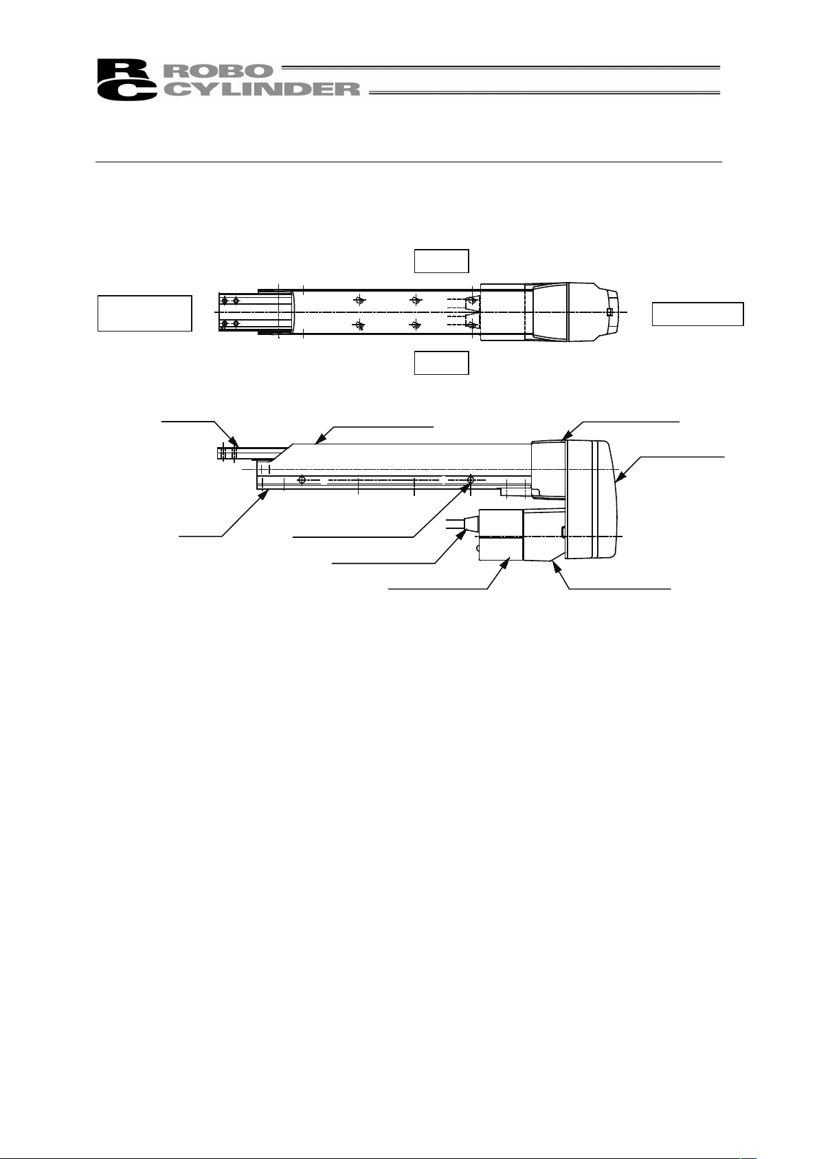
Names of the Parts
In this Operation Manual, the left and right sides are indicated by looking at the actuator from the
motor end, with the actuator placed horizontally, as shown in the figure below.
�
�
Slider
Opposite Side
of the Motor
Encoder Cover
Actuator Cable
Screw Cover
Base
Screw Cover
Mounting Screw
Motor Bracket
Pulley Cover
Motor Housing
Motor Side
Right
Left
�
�
�
�
�
�
�
�
�
�
�
�
�
�
�
�
�
�
�
�
Page 17

11
1. Specifications Check
1.1 Checking the Product
The standard configuration of this product is comprised of the following parts.
See the component list for the details of the enclosed components. If you find any faulty or missing
parts, contact your local IAI distributor.
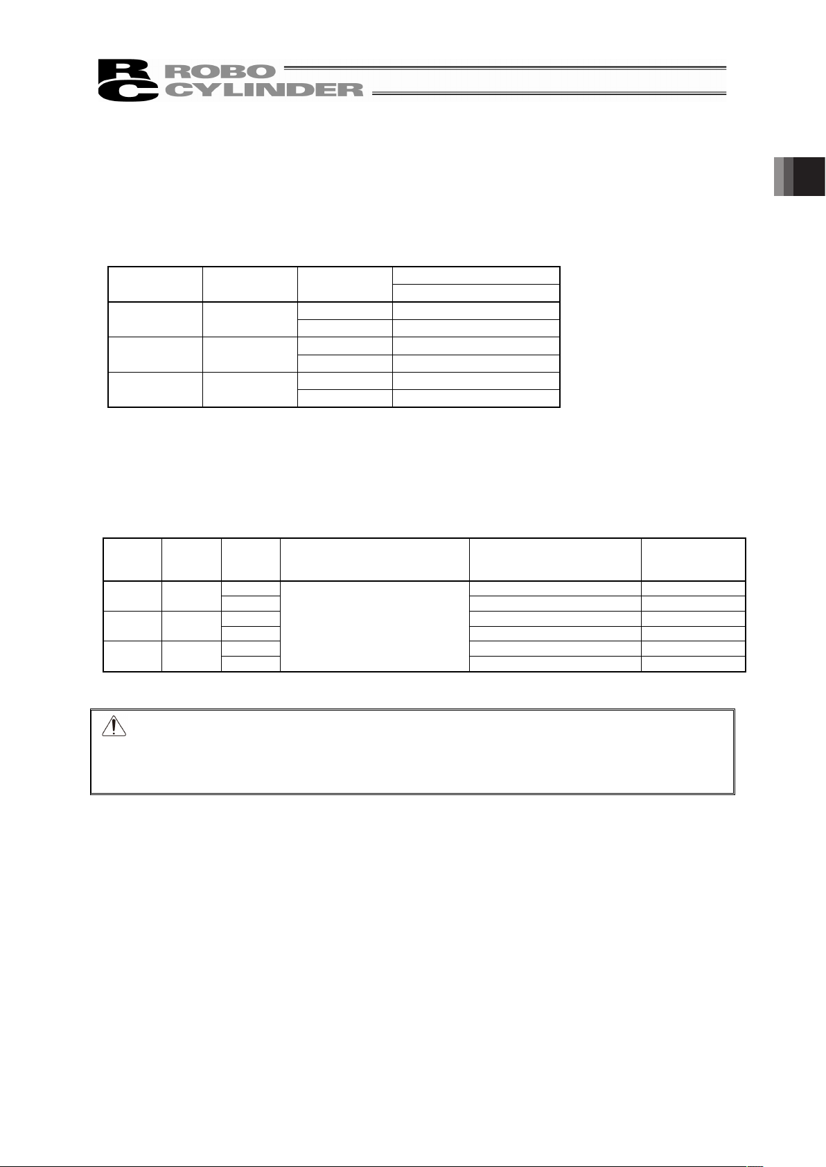
1.1.1 Parts
No. Name Model number Quantity Remarks
1 Actuator
Refer to “How to Read the Model
Nameplate” and “How to Read
the Model Number.”
1
Accessories
2
Motor • encoder cables
(Note1)
1 set
3 First Step Guide 1
4 Operation Manual (DVD) 1
5 Safety Guide 1
Note1 The motor • encoder cables differ between the standard model and robot cable.
[Refer to 1.4, “Motor • Encoder Cables.”]
1.1.2 Operation Manuals for the Controllers Related to this Product
[1] Manuals Related to Controllers for RCA Actuator
No. Name Control No.
1 Operation Manual for ASEL Controller ME0165
2 Operation Manual for ACON-C/CG Controller ME0176
3 Operation Manual for ACON-CY Controller ME0167
4 Operation Manual for ACON-SE Controller ME0171
5 Operation Manual for ACON-PL/PO Controller ME0166
6 Operation Manual for AMEC Controller ME0245
7 Operation Manual for ASEP/PSEP Controller ME0216
8 Operation Manual for MSEP Controller ME0299
9 Operation Manual for PC Software IA-101-X-MW/IA-101-X-USBMW ME0154
10 Operation Manual for PC Software RCM-101-MW/RCM-101-USB ME0155
11 Operation Manual for MEC PC Software ME0248
12 Operation Manual for Teaching Pendant SEL-T/TD ME0183
13 Operation Manual for Teaching Pendant CON-T/TG ME0178
14 Operation Manual for Touch Panel Teaching CON-PT/PD/PG ME0227
15 Operation Manual for Touch Panel Teaching CON-PTA/PDA/PGA ME0295
16 Operation Manual for Touch Panel Teaching SEP-PT ME0217
17 Operation Manual for Simple Teaching Pendant RCM-E ME0174
18 Operation Manual for Data Setter RCM-P ME0175
19 Operation Manual for Data Setter RCM-PM-01 ME0182
1. Specications Check
Page 18

1. Specications Check
12
[2]
Manuals Related to Controllers for RCS2 Actuator
(1) Manuals Related to XSEL-J/K Controllers
No. Name Control No.
1 Operation Manual for XSEL-J/K Controller ME0116
2 Operation Manual for PC Software IA-101-X-MW/IA-101-X-USBMW ME0154
3 Operation Manual for Teaching Pendant SEL-T/TD/TG ME0183
4 Operation Manual for Teaching Pendant IA-T-X/XD ME0160
5 Operation Manual for DeviceNet ME0124
6 Operation Manual for CC-Link ME0123
7 Operation Manual for PROFIBUS ME0153
8 Operation Manual for X-SEL EtherNet ME0140
9 Operation Manual for Multi-Point I/O Board ME0138
10 Operation Manual for Multi-Point I/O Board Dedicated Terminal Board ME0139
(2) Manuals Related to XSEL-P/Q Controllers
No. Name Control No.
1 Operation Manual for XSEL-P/Q Controller ME0148
2 Operation Manual for XSEL-P/Q/PX/QX RC Gateway Function� ME0188
3 Operation Manual for PC Software IA-101-X-MW/IA-101-X-USBMW ME0154
4 Operation Manual for Teaching Pendant SEL-T/TD/TG ME0183
5 Operation Manual for Teaching Pendant IA-T-X/XD ME0160
6 Operation Manual for DeviceNet ME0124
7 Operation Manual for CC-Link ME0123
8 Operation Manual for PROFIBUS ME0153
(3) Manuals Related to SSEL Controllers
No. Name Control No.
1 Operation Manual for SSEL Controller ME0157
2 Operation Manual for PC Software IA-101-X-MW/IA-101-X-USBMW� ME0154
3 Operation Manual for Teaching Pendant SEL-T/TD/TG ME0183
4 Operation Manual for Teaching Pendant IA-T-X/XD ME0160
5 Operation Manual for DeviceNet ME0124
6 Operation Manual for CC-Link ME0123
7 Operation Manual for PROFIBUS ME0153
Page 19
13
(4) Manuals Related to SCON Controllers
No. Name Control No.
1 Operation Manual for SCON Controller ME0161
2 Operation Manual for SCON-CA Controller SCON-CA� ME0243
3 Operation Manual for PC Software RCM-101-MW/RCM-101-USB ME0155
4 Operation Manual for Teaching Pendant CON-T/TG ME0178
5 Operation Manual for Touch Panel Teaching CON-PT/PD/PG ME0227
6 Operation Manual for Simplified Teaching Pendant RCM-E ME0174
7 Operation Manual for Data setter RCM-P ME0175
8 Operation Manual for Touch Panel Display RCM-PM-01 ME0182
9 Operation Manual for DeviceNet ME0124
10 Operation Manual for CC-Link ME0123
11 Operation Manual for PROFIBUS ME0153
1.1.3 How to Read the Model Nameplate
Model
Serial Numbe
r
MODEL RCA-A4R-I-20-10-50-A1-P-B
SERIAL No.200090266 MADE IN JAPAN
1. Specications Check
Page 20
1. Specications Check
14
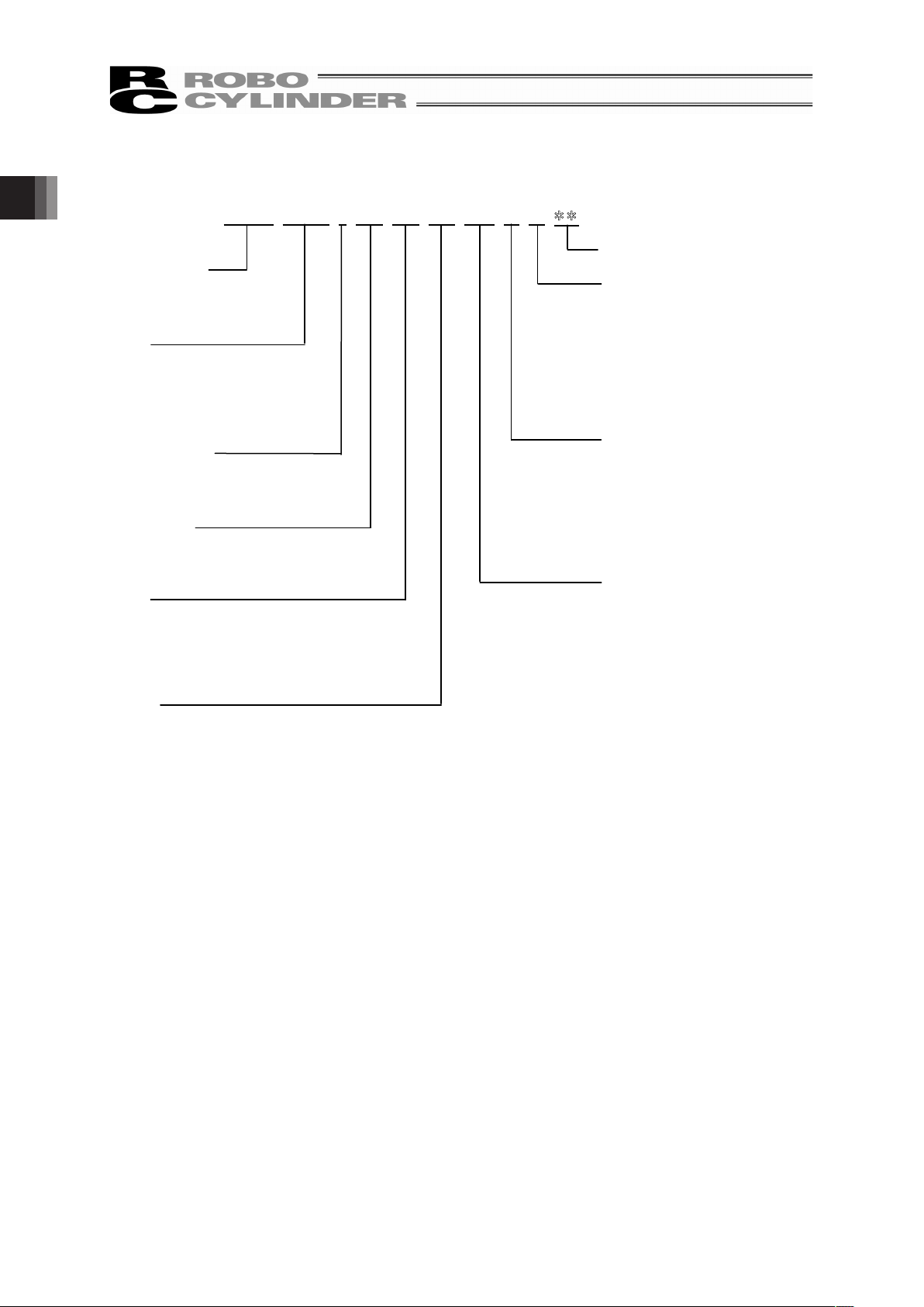
1.1.4 How to Read the Model Number
R C A - A 4 R - I - 2 0 - 1 0 - 5 0 - A 1 - P - B -
Note 1 Identification for IAI use only : It may be displayed for IAI use. It is not a code to show
the model type.
<Series Name>
RCA
RCS2
<Type>
Arm Type
A4R
A5R
A6R
<Encoder Type>
I : Incremental
A : Absolute
<Motor Type>
20 : 20W
30 : 30W
<Lead>
5 : 5mm
6 : 6mm
10 : 10mm
12 : 12mm
<Stroke>
Identification for IAI use only
(Note1)
<Options>
B : Brake
LA : Low Power Consumption Type
NM : Reversed-home type
MB : Motor Bottom Reversed Type
MR : Motor Right Reversed Type
ML : Motor Left Reversed Type
CE : CE Mark Complied
<Cable length>
N : None
P : 1m
S : 3m
M : 5m
X�� : Length Specification
R�� : Robot Cable
<Controller>
A1 : ACON-C/CG
ACON-CY
ACON-SE
ACON-PL/PO
RACON
ASEL
A3
: AMEC
ASEP
T1
: XSEL-J/K
T2
: SCON
SSEL
XSEL-P/Q
Page 21
15
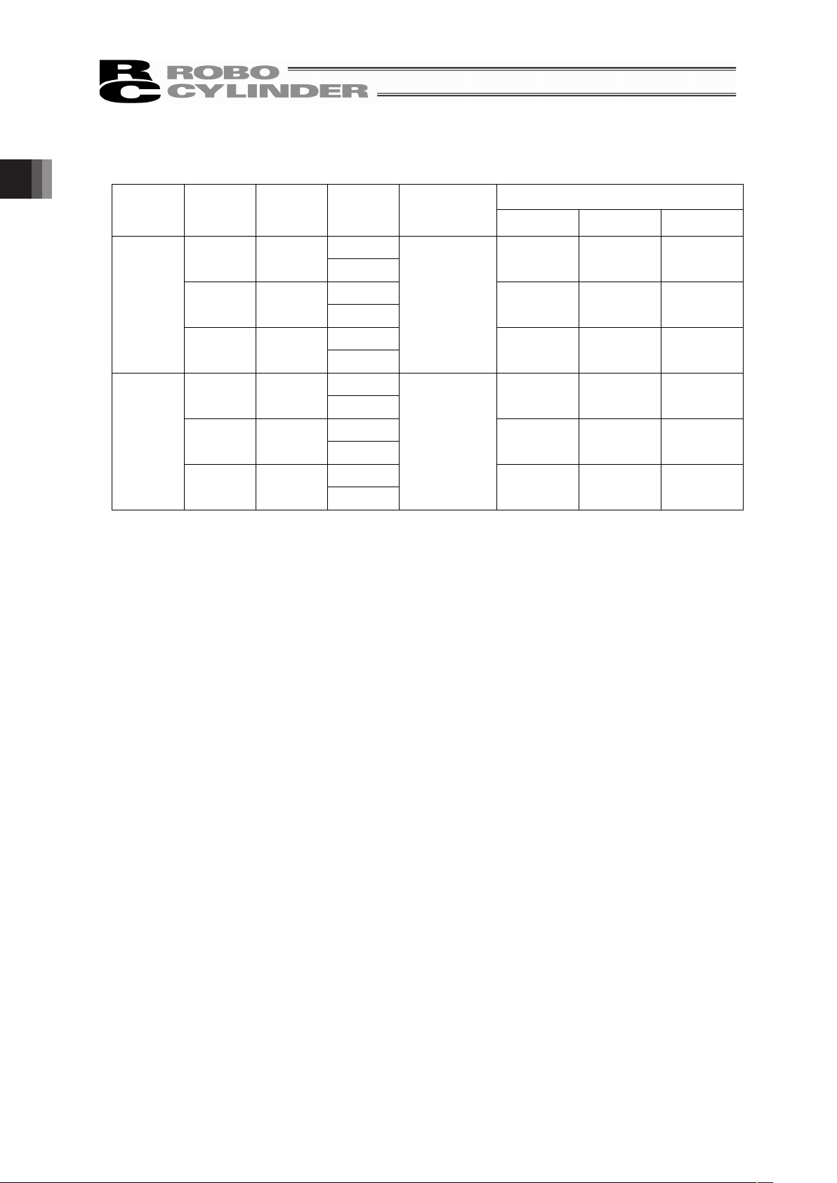
1.2 Specification
1.2.1 Speed
�
�
Speed limits (Unit: mm/s)�
Stroke [mm]�
Size Motor Type Lead [mm]
50 to 200 (Every 50mm)
10 330
A4R 20W
5 165
12 400
A5R 20W
6 200
12 400
A6R 30W
6 200
1.2.2 Maximum Acceleration and Transportable Weight
�
When the transported weight is low, the acceleration/deceleration and speed can be increased.
Type
Motor
Type
�
Lead
[mm]
�
Acceleration/Deceleration
[
G]�
Transportable Weight
[
kg]
Rated Thrust�
[N]
10 2.5 39.2
A4R 20W
5 4.5 78.4
12 2 33.3
A5R 20W
6 4 65.7
12 3 48.4
A6R 30W
6
0.2
6 96.8
Caution: Do not have the settings of speed and acceleration/deceleration exceeding the
rated values. It may cause vibration, malfunction or shortened life. Setting of
acceleration/deceleration above the ratings may cause creeping or slippage of the
coupling.
�
1. Specications Check
Page 22
1. Specications Check
16
1.2.3 Driving System • Position Detector
Ball Screw Type
Series Type
Motor
Type
Lead
No. of
Encoder
Pulses
Type Diameter Accuracy
10
A4R 20W
5
Rolled
�8
C10
12
A5R 20W
6
Rolled
�8
C10
12
RCA
A6R 30W
6
800
Rolled
�10
C10
10
A4R 20W
5
Rolled
�8
C10
12
A5R 20W
6
Rolled
�8
C10
12
RCS2
A6R 30W
6
16,384
Rolled
�10
C10
1.2.4 Positioning Repeatability
�
±0.02 [mm]
1.2.5 Lost Motion
�
0.1 [mm] or less
The values shown above are the accuracy at the delivery from the factory. It does not include
the consideration of time-dependent change as it is used.
Page 23

17
1.2.6 Allowable Load Moments of the Actuator
Allowable Dynamic Load Moment [Nm] ([kgfm])
Type
Ma Mb Mc
A4R 2.7 (0.28) 3.1 (0.32) 2.9 (0.30)
A5R 4.5 (0.46) 5.4 (0.55) 4.1 (0.42)
A6R 8.1 (0.83) 10.0 (1.02) 6.5 (0.66)
MaMc
Mb
Directions of the load moments
Thrust
direction
Thrust
direction
1. Specications Check
Page 24

1. Specications Check
18
1.3 Options
1.3.1 Brake Type (Model: B)
This is a protection structure not to damage the attached objects by the rod being dropped when
the power of the servo is turned OFF in case the actuator is mounted vertically.
1.3.2 Low Power Consumption Type (Model: LA)
It is an option to decrease the power consumption of the controller.
By selecting the low power consumption type, the consumption drops to 3.4A at maximum,
where it is 5.1A at maximum in Standard type/High acceleration and deceleration type.
1.3.3 Reversed-home Type (Model: NM)
Even though the home position is placed on the motor side in normal type, the home position
can be set on the other side by the option when it is required due to a reason such as the layout
of the equipment.
1.3.4 Motor Reversed Directions (Model: NM, ML, MR)
These symbols are the indication for the directions of the motor reversing in the motor reversed
type.
From the view of the motor end, reversing on the bottom is MB, on the left is ML and on the right
is MR.
MB is the standard for the arm type.
1.3.5 CE Mark Complied (Model: CE)
It shows the compliance with CE Mark.
Actuator
R
(RIGHT)
L
(LEFT)
B
(BOTTOM)
Page 25

19
1.4 Motor • Encoder Cables
1.4.1 Motor • Encoder Integrated Cables for the RCA Actuator
[1] Motor Cable
Model : CB-ACS-MA��
1
3
Controller Side Mechanical Side
Width
Electric
Wire
Color
Signal
Name
Pin No.
Pin No.
Signal
Name
Electric
Wire
Color
Width
Red U 1
1 U Red
White� V 2 � � � � 2 V White�
AWG22
(Solderless)
Black� W 3
�
� � � 3 W Black�
AWG22
(Solderless)
1. Specications Check
Page 26

1. Specications Check
20
[2] Encoder Cable • Encoder Robot Cable
Model : CB-ACS-PA��� • CB-ACS-PA���-RB
18 17
2 1
9 18
1 10
Controller Side Mechanical Side
Signal Name
Pin No.
For ABS For Serial
Electric Wire
Color
Width
Width
Electric Wire
Colo
r
Signal
Name
Pin No.
1 A+ -
White/
Blue
White/Purple
LS+
18
2 A- -
White/
Yellow
White/Gray
LS-
17
3 B+ -
White/
Red
Yellow
BK+
16
4 B- -
White/
Black
Blue BK-
15
5 - - -
White/
Blue A+
14
6 - - -
White/Yellow
A-
13
7 LS+ LS+
White/Purple
White/
Red B+
12
8 - - -
White/
Black B-
11
9 FG FG Ground
Orange SD/Z
10
10 Z+ SD+ Orange
Green SD/Z
9
11 Z- SD- Green
Purple
BAT+
8
12 - BAT+
Purple
Gray
BAT-
7
13 /PS BAT-
Gray
Red VCC
6
14 VCC VCC Red
Black GND
5
15 GND GND Black
-
4
16 LS- LS-
White/Gray
-
3
17 BK- BK- Blue
-
2
18 BK+ BK+ Yellow
AWG26
(Solderless)
AWG26
(Solderless)
Ground FG
1
Page 27

21
[3] Motor • Encoder Integrated Cables for AMEC/ASEP
Model : CB-ASEP-MPA���
Controller Side
Mechanical Side
Width
Electric
Wire Color
Signal
Name
Pin No.
� � � �
Pin No.
Signal
Name
Electric
Wire Color
Width
Red U 1
� � � �
1 U Red
Yellow V 2
� � � �
2 V Yellow
NC
� � � �
3 NC
NC
� � � �
4 NC
AWG22
(Solderless)
Black W 3
� � � �
5 W Black
AWG22
(Solderless)
NC
� � � �
6 NC
Orange BK+ 18
� � � �
7 BK+ Orange
Gray BK- 17
� � � �
8 BK- Gray
Black LS+ 7
� � � �
9 LS+ Black
Brown LS- 16
� � � �
10 LS- Brown
White A+ 1
� � � �
11 A+ White
Yellow A- 2
� � � �
12 A- Yellow
Red B+ 3
� � � �
13 B+ Red
Green B- 4
� � � �
14 B- Green
Black
Z+ 10
� � � �
15 Z+
Black
Brown
Z- 11
� � � �
16 Z-
Brown
White
VCC 14
� � � �
17 VCC
White
Yellow
VPS 13
� � � �
18 VPS
Yellow
Red
GND 15
� � � �
19 GND
Red
Green
Identification Tape
Spare 6
� � � �
20 Spare
Green
Identification Tape
NC 5
� � � �
21 NC
� NC 8
� � � �
22 NC
� NC 12
� � � �
23 NC
AWG26
(Solderless)
� FG 9
� � � �
24 FG
AWG26
(Solderless)
1. Specications Check
Page 28

1. Specications Check
22
1.4.2 Motor • Encoder Integrated Cables for the RCS2 Actuator
[1] Motor Cable • Motor Robot Cable
Model : CB-RCC-MA��� • CB-RCC-MA���-RB
4
1
1
4
(16) (20)
(41)
Controller side
Mechanical Side
(Front View)(Front View)
(
φ
9)
(21)
L
(20)
(10)
(18)
Width
Electric Wire
Color
Signal
Name
Pin
No.
Pin
No.
Signal
Name
Electric Wire
Color
Width
Green
PE 1 1 U
Red
Red
U 2 2 V White
White V 3 3 W Black
AWG18
Black W 4 4 PE Green
AWG18
(
Solderless
)
Page 29

23
[2] Encoder Cable � Encoder Robot Cable [For SCON, SSEL, XSEL-P/Q]
Model : CB-RCS2-PA��� • CB-RCS2-PA���-RB
L
Controller side Mechanical Side
(Front View)(Front View)
(13)
(37)
(41)
(14)
(25)
(15)
1 10
9
18
1
13
14
26
Width
Electric Wire
Color
Signal
Name
Pin No.
-
-
10
-
-
11
- E24V
12
Gray/White
0V
13
Brown
/White
LS
26
-
CREEP
25
- OT
24
- RSV
23
- -
9
- - 18
- -
19
Pin No.
Signal
Name
Electric Wire
Color
Width
Pink A+
1
1 A Pink
Purple A-
2
2
A
Purple
White B+
3
3 B White
Blue/Red B-
4
4
B
Blue/Red
Orange/White
Z+
5
5 Z
Orange/White
Green/White
Z-
6
6
Z
Green/White
Blue SRD+
7
7 LS+ Brown
/White
Orange SRD-
8
8 - -
Black BAT+
14
9 FG Ground
Yellow BAT-
15
10 SD Blue
Green VCC
16
11
SD
Orange
Brown GND
17
14 BAT+ Black
Gray BKR-
20
13 BAT- Yellow
Red BKR+
21
14 VCC Green
AWG26
(Soldered)
- -
22
15 GND Brown
The shield is clamped to the hood
16 LS-
Gray/White
17 BK- Gray
18 BK+ Red
AWG26
(Solderless)
Ground wire and braided shield wires
1. Specications Check
Page 30

24
[3] Encoder Cable • Encoder Robot Cable [For XSEL-J/K]
Model : CB-RCBC-PA��� • CB-RCBC-PA���-RB
Controller side
Mechanical Side
1,10
9,18
(36)
(16)
(33)
(57)
(Front View)
(15)
(14)
(25)
(
φ
8)
L
(Front View)
Width
Electric Wire
Color
Signal
Name
Pin No.
� � � �
Pin No.
Signal
Name
Electric Wire
Color
Width
Pink A/U
1
� � � �
1 A/U Pink
Purple
A/U
2
� � � �
2
A/U
Purple
White B/V
3
� � � �
3 B/V White
Blue/Red
B/V
4
� � � �
4
B/V
Blue/Red
Orange/White
Z/W
5
� � � �
5 Z/W
Orange/White
Green/White
Z/W
6
� � � �
6
Z/W
Green/White
Blue SD 7
� � � �
7 - -
Orange
SD
8
� � � �
8 - -
Black BAT+ 9
� � � �
9 FG Ground
Yellow BAT- 10
� � � �
10 SD Blue
Green VCC
11
� � � �
11
SD
Orange
Brown GND 12
� � � �
12 BAT+ Black
Gray BK- 13
� � � �
13 BAT- Yellow
Red BK+ 14
� � � �
14 VCC Green
AWG25
(Soldered)
- - 15
� � � �
15 GND Brown
The shield is clamped to the hood
� � � � �
16 - -
�
� � � � �
17 BK- Gray
�
� � � � �
18 BK+ Red
AWG25
(Solderless)
1. Specications Check
Page 31

25
2. Installation�
2.1 Transportation
[1] Handling of the Actuator
Unless otherwise specified, the actuator is shipped with 1 axis unit packaged separately.
(1) Handling the Packed Unit
� Do not damage or drop. The package is not applied with any special treatment that enables it to
resist an impact caused by a drop or crash.
� Transport a heavy package with at least more than two operators. Consider an appropriate
method for transportation.
� Keep the unit in horizontal orientation when placing it on the ground or transporting. Follow the
instruction if there is any for the packaging condition.
� Do not step or sit on the package.
� Do not put any load that may cause a deformation or breakage of the package.
(2) Handling the Actuator After Unpacking
� Do not carry the actuator by its motor unit or its cable or attempt to move it by pulling the cable.
� Hold the base part or bracket part of the body when transporting the actuator main body.
� Do not hit or drop the actuator during transportation.
� Do not attempt to force any part of the actuator.
2. Installation
Page 32

2. Installation
26
[2] Handling in Assembled Condition
This is the case when the product is delivered from our factory under a condition that it is assembled
with other actuators. The combined axes are delivered in a package that the frame is nailed on the
lumber base. The rods are fixed so they would not accidently move. The actuators are also fixed so
the tip of it would not shake due to the external vibration.
(1) How to Handle in Package
� Do not hit or drop the package. No special treatment is conducted on this package to
endure a drop or impact on it.
� Do not attempt to carry a heavy package with only one worker. Also, have an appropriate
method for transportation.
� When hanging up with ropes, support on the reinforcement frame on the bottom of the
lumber base. When bringing up the package with a forklift, also support on the bottom of
the lumber base.
� Handle with care when putting the package down to avoid impact or bounce.
� Do not step on the package.
� Do not put anything on the package that could deform or damage it.
(2) How to Handle after Unpackaged
� Fix the rod so they would not accidently move during transportation.
� If the tip of an actuator is overhanging, have an appropriate way to fix it to avoid shake due
to the external vibration. In the transportation without the tip being fixed, do not apply any
impact with 0.3G or more.
� When hanging up with ropes, have appropriate cushioning to avoid any deformation of the
actuator body. Also keep it in stable horizontal orientation. Make a fixture utilizing the
attachment holes and the tapped holes on the actuator body if necessary.
� Do not attempt to apply load on the actuators or the connector box. Also pay attention not
to pinch cables and bend or deform them forcefully.
[3] Handling in Condition of being assembled in Machinery Equipment (System)
This is some caution notes for when transporting the actuator being assembled in the
machinery equipment (system).
� Fix the table so they would not move during transportation.
� If the tip of an actuator is overhanging, have an appropriate way to fix it to avoid shake due
to the external vibration. In the transportation without the tip being fixed, do not apply any
impact with 0.3G or more.
� When hanging up the machinery equipment (system) with ropes, do not attempt to apply
load on the actuators or the connector box. Also pay attention not to pinch cables and bend
or deform them forcefully.
Page 33

27
2.2 Installation and Storage • Preservation Environment
[1] Installation Environment
The actuator should be installed in a location other than those specified below.
In general, the installation environment should be one in which an operator can work without
protective gear.
Also provide sufficient work space required for maintenance inspection.
� Where the actuator receives radiant heat from strong heat sources such as heat treatment
furnaces
� Where the ambient temperature exceeds the range of 0 to 40�C
� Where the temperature changes rapidly and condensation occurs
� Where the relative humidity exceeds 85% RH
� This actuator possesses the water durability of IP67 protection structure.
� Where the actuator receives direct sunlight
� Where the actuator is exposed to corrosive or combustible gases
� Where the ambient air contains a large amount of powder dust, salt or iron (at level
exceeding what is normally expected in an assembly plant)
� Where the actuator receives impact or vibration
If the actuator is used in any of the following locations, provide sufficient shielding measures:
� Where noise generates due to static electricity, etc.
� Where the actuator is subject to a strong electric or magnetic field
� Where the actuator is subject to ultraviolet ray or radiation
[2] Storage • Preservation Environment
� The storage and preservation environment should comply with the same standards as
those for the installation environment. In particular, when the machine is to be stored for a
long time, pay close attention to environmental conditions so that no dew condensation
forms.
� Unless specially specified, moisture absorbency protection is not included in the package
when the machine is delivered. In the case that the machine is to be stored and preserved
in an environment where dew condensation is anticipated, take the condensation
preventive measures from outside of the entire package, or directly after opening the
package.
� For storage and preservation temperature, the machine withstands temperatures up to
60�C for a short time, but in the case of the storage and preservation period of 1 month or
more, control the temperature to 50�C or less.
� Storage and preservation should be performed in the horizontal condition. In the case it is
stored in the packaged condition, follow the posture instruction if any displayed on the
package.
�
2. Installation
Page 34

2. Installation
28
2.3 How to Install
This chapter explains how to install the actuator on your mechanical system.
2.3.1 General Rules on Installation
Follow the information below when installing the actuator, as a rule.
Do pay attention to these items (except with custom-order models).
� : Possible � : Not possible
Horizontal
installation
Vertical
installation
Sideway
installation
Ceiling Mount
�
�
� �
Installation Orientation
Horizontal Vertical
Sideway
Ceiling Mount
Page 35

29
2.3.2 Installation of Main Unit
The surface to mount the main unit should be a machined surface or a plane that possesses an
equivalent accuracy and the flatness should be within 0.05mm/m.
Install the main body as follows:
About Tightening Screws
� Use a hex socket head cap bolt for the attachment to the base.
� It is recommended to use high-tensile bolts with ISO-10.9 or more.
� Make sure to have the effective length of bolt engagement described below or more for the
tightening of a bolt and a female screw.
When female screw is on steel � Thread length same as nominal diameter
When female screw is on aluminum � Thread length 2 times longer them nominal diameter
Caution: Pay special attention when selecting the bolt length. In case that an inappropriate
length of a bolt is applied, it may cause a drop in the operation accuracy or an
unexpected accident due to a damage, insufficient strength of actuator attachment
or an interference with the operating area.
Pull out the slider to the stroke end. Remove four screw
cover mounting screws with an Allen wrench of 1.5mm
across flats to remove the screw cover.
If the actuator has a brake, connect this machine to the controller and pull out the slider to the stroke
end after the brake has been released with the brake release switch. Then, turn OFF the controller
power for safety.
Check to see that a 0.1mm thick gauge cannot be inserted
at the mounting holes while this machine is left standing
on the mounting surface.
2. Installation
Page 36

2. Installation
30
Type
In the case that steel is used for
the bolt seating surface:
In the case that aluminum is used
for the bolt seating surface:
A4R M3×8 M3×12
A5R M4×8 M4×12
A6R M5×10 M5×15
Caution: Pay special attention when selecting the bolt length. In case that an inappropriate
length of a bolt is applied, it may cause a drop in the operation accuracy or an
unexpected accident due to a damage, insufficient strength of actuator attachment
or an interference with the operating area.
2.3.3 Mounting Surface
� The platform to install the actuator should possess a structure that ensures enough stiffness,
and should be free from vibration.
� The surface where the actuator will be mounted should be a machined surface or that with an
accuracy equivalent to it, and the flatness should be 0.05mm/m or below.
� Have enough space for the maintenance work.
The side and bottom surfaces of the base on the actuator work as the datum surfaces for the side
of the slider.
Secure the main body with the mounting holes
on the base of this machine.
Use the hexagon socket head bolts shown
below.
After securing the main body, reinstall the
screw cover.
Page 37

31
2.3.4 Attachment of the Transported Object
� Use four M4 screws to install the transported object to the slider.
Caution: Check to see that the workpiece seating surface is flat to prevent the slider from
becoming deformed when the workpiece is installed.
Slider deformation may cause it to move rigidly or shorter its life.
Caution: Do not exceed the maximum mass capacity.
Please make note of the slider moment, allowable overhang length and load
weight.
Tapped hole to install
the work
p
iece
Slider
Slider
Workpiece
A
Set the dimension of an overhang above the
workpiece to the value shown below to prevent
interference with the screw cover and workpiece.�
Type Size
A4R A=53mm
A5R A=65mm
A6R A=70mm
2. Installation
Page 38

3. Connecting with the Controller
32
3. Connecting with the Controller
As the connection cable for the controller and actuator, use the IAI-dedicated controller and
dedicated connection cable.
This section explains the wiring method for a single axis.
If the dedicated connection cable cannot be secured, reduce the load on the cable by allowing it
to deflect only by the weight of the cable or wire it in a self-standing cable hose, etc., having a
large radius.
Do not cut and reconnect the dedicated connection cable for extension or shorten the cable.
Do not pull on the dedicated connection cable or bend it forcibly.
The actuator cable coming out of the motor unit is not meant to be bent. Fix the cable so it would
not be bent repeatedly.
Please consult with IAI if you require a different kind of cable than the one supplied.
RCA Actuator
[Connection with the ACON, ASEL controller]
Dedicated cables
Motor cable Robot cableCB-ACS-MA���
Encoder cable CB-ACS-PA��� / Robot encoder cable CB-ACS-PA���-RB
��� indicates the cable length. A desired length up to 20m can be specified.
Example) 080 = 8m
Dedicated Connection Cable
(Connect RCA with the dedicated controller.)
r
r
Dedicated Controller
ACON
ASEL
Robot Cable
r = 54mm or more (Movable Use)
Standard Cable
r = 75mm or more (Fixed Use)
Use robot cables if the cables tend to move.
Page 39

33
[Connection with the AMEC, ASEP controller]
�
�
�
�
�
�
�
�
�
�
�
�
�
�
�
�
�
Dedicated cables
� Motor encoder cable�CB-ASEP-MA���
��� indicates the cable length. A desired length up to 20m can be specified.
Example) 080 = 8m
�
�
�
�
�
r
r = 68mm or more (Movable Use)
r = 34mm or more (Fixed Use)
Dedicated Controller
AMEC, ASEP
Dedicated Connection Cable
(Connect RCA with the dedicated controller.)
3. Connecting with the Controller
Page 40

3. Connecting with the Controller
34
RCS2 Actuator
[Connection with the SCON, SSEL controller]
�
�
�
�
�
�
�
�
�
�
�
�
�
�
�
�
�
�
�
Dedicated cables
� Motor cable�CB-RCC-MA��� / Robot motor cable CB-RCC-MA���-RB
� Encoder cable CB-RCS2-PA��� / Robot encoder cable CB-X3-PA���
��� indicates the cable length. A desired length up to 30m can be specified.
Example) 080 = 8m
�
�
�
[Connection with the X-SEL controller]
�
�
�
�
�
�
�
�
�
�
�
�
�
�
�
�
�
�
�
�
Dedicated cables
� Motor cable CB-RCC-MA��� / Robot motor cable CB-RCC-MA���-RB
� X-SEL-J/K encoder cable CB-RCBC-PA��� / X-SEL-J/K robot encoder cable
CB-RCBC-PA���-RB
� X-SEL-P/Q encoder cable CB-RCS2-PA��� / X-SEL-P/Q robot encoder cable CB-X3-PA���
��� indicates the cable length. A desired length up to 15m can be specified.
For other cables, a desired length up to 20m can be specified.
Example) 080 = 8m
Dedicated Connection Cable
(Connect RCS2 with the dedicated controller.)
r
r
Dedicated Controller
SCON
SSEL
Robot Cable
r = 58mm or more (Movable Use)
Standard Cable
r = 93mm or more (Fixed Use)
Use robot cables if the cables tend to move.
Dedicated Connection Cable
(Connect RCS2 with the dedicated controller.)
r
r
Dedicated Controller
XSEL
Robot Cable
r = 58mm or more (Movable Use)
Standard Cable
r = 93mm or more (Fixed Use)
Use robot cables if the cables tend to move.
Page 41

35
Warning: For wiring, please follow the warnings stated below. When constructing a
system as the machinery equipment, pay attention to the wiring and
connection of each cable so they are conducted properly. Not following them
may cause not only a malfunction such as cable breakage or connection
failure, or an operation error, but also electric shock or electric leakage, or
may even cause a fire.
• Use dedicated cables of IAI indicated in this instruction manual. Contact us if you
wish to have a change to the specifications of the dedicated cables.
• Make sure to turn the power off in the process of power line or cable connection or
disconnection.
• Do not attempt to cut a dedicated cable with connectors on both ends to extend,
shorten or re-joint it.
• Hold the dedicated cable to avoid mechanical force being applied to the terminals and
connectors.
• Use a cable pipe or duct to have an appropriate protection when there is a possibility
of mechanical damage on a dedicated cable.
• In case a dedicated cable is to be used at a moving part, make sure to lay out the
cable without applying any force to pull the connector or extreme bend on the cable.
Do not attempt to use the cable with a bending radius below the allowable value.
• Make certain that the connectors are plugged properly. Insufficient connection may
cause an operation error, thus it is extremely risky.
• Do not lay out the cables to where the machine runs over them.
• Pay attention to the cable layout so it would not hit peripherals during an operation. In
case it does, have an appropriate protection such as a cable track.
• When a cable is used hanging on the ceiling, prevent an environment that the cable
swings with acceleration or wind velocity.
• Make sure there is not too much friction inside the cable storage equipment.
• Do not apply radiated heat to power line or cables.
• Have a sufficient radius for bending, and avoid a bend concentrating on one point.
Steel Strap
(Piano Wire)
Tie them up softly.
3. Connecting with the Controller
Page 42

3. Connecting with the Controller
36
• Do not let the cable bend, kink or twist.
• Do not pull the cable with a strong force.
• Pay attention not to concentrate the twisting force to one point on a cable.
• Do not pinch, drop a heavy object onto or cut the cable.
• When a cable is fastened to affix, make sure to have an appropriate force and do not
tighten too much.
Do not use spiral tube in any
position where cables are bent
frequently.
Page 43

37
• PIO line, communication line, power and driving lines are to be put separately from
each other and do not tie them together. Arrange so that such lines are independently
routed in the duct.
Follow the instructions below when using a cable track.
• If there is an indication to the cable for the space factor in a cable track, refer to the
wiring instruction given by the supplier when storing the cable in the cable track.
• Avoid the cables to get twined or twisted in the cable track, and also to have the
cables move freely and do not tie them up. (Avoid tension being applied when the
cables are bent.)
Do not pile up cables. It may cause faster abrasion of the sheaths or cable breakage.
Power line
I/O lines (flat cable)
Duct
3. Connecting with the Controller
Page 44

4. Maintenance Inspection
38
4. Maintenance Inspection
4.1 Inspection Items and Schedule
Follow the maintenance inspection schedule below.
It is assumed that the equipment is operating 8 hours per day.
If the equipment is running continuously night and day or otherwise running at a high operating
rate, inspect more often as needed.
�
External visual
inspection
Internal inspection Greasing
Start of work inspection
��
� �
After 1 month of operation
�
� �
After 6 months of operation
� ��
�
After 1 year of operation
� �� ��
Every 6 months thereafter
�
�
Every 1 year
� � ��
4.2 External Visual Inspection
An external visual inspection should check the following things.�
Main unit Loose actuator mounting bolts, other loose items
Cables Scratches, proper connections
Overall Irregular noise, vibration
�
4.3 Cleaning
� Clean the exterior as needed.
� Wipe off dirt with a soft cloth.
� Do not use strong compressed air on the actuator as this may force dust into the crevices.
� Do not use petroleum-based solvents on plastic parts or painted surfaces since such solvents
damage them.
� If the unit is badly soiled, apply a neutral detergent or alcohol to a soft cloth, and wipe gently.
Page 45

39
4.4 Interior Inspection
�
Turn off the power, remove the side covers, and then visually inspect the interior.
Check the following items during interior inspection.
Main unit Loose mounting bolts
Guides Lubrication appropriate, Soiling
Ball screw Lubrication appropriate, Soiling
�
How to inspect the interior:
(1) Remove both side covers.
Use an Allen wrench of 1.5mm across flats.
Make a visual check of the interior or to see if
there is
any dust or to see if there is any dust or foreign
matter
in the unit and check the lubrication.
Even if the grease you see around the parts is
brown,
the lubrication is fine as long as the traveling
surface
appears shiny.
(2) If the grease becomes dirty and dull or if the grease has worn away due to extended operating
time, lubricate the parts after cleaning them.
(3) When the inspection/maintenance work is complete, install the side covers.
Tightening torque: Thin-head screw M3 × 6 87.2N·cm (8.90kgf·cm)
4. Maintenance Inspection
Page 46

4. Maintenance Inspection
40
4.5 Internal Cleaning
� Use a soft cloth to wipe away dirt and buildup.
� Do not use strong compressed air on the actuator as this may force dust into the crevices.
� Do not use petroleum-based solvent, neutral detergent or alcohol.
Caution: Do not use flushing oil, molybdenum grease or anti-rust lubricant.
When grease is soiled with a large amount of foreign substances, wipe off the
dirty grease and then apply new grease.
4.6 Grease supply
4.6.1 Applicable greases
(1) What Grease to Use on the Guides
IAI uses the following grease in our plant.
Idemitsu Kosan Daphne Eponex Grease No.2
Other companies also sell similar types of grease. Fordetails, give the above grease name to
the manufacturer you want to purchase from and ask what corresponding product they have
available. Here are some examples of similar products.
Showa Shell Oil Albania Grease No. 2
Mobil Oil Mobilax 2
(2) Applicable greases for ball screw
IAI uses the following grease in our plant.
This grease offers excellent properties such as low heat generation, and is suitable for
lubricating ball screws.
Kyodo Yushi Multitemp LRL 3
Warning: Never use fluorine-based grease.
It will cause a chemical reaction when mixed with a lithium-based grease and
may cause damage to the actuator.
Page 47

41
4.6.2 How to Apply Grease
(1) When greasing the ball screw, apply grease using a finger and then move the slider back and
forth several times to let the grease spread evenly.
(2) When greasing the slider, apply grease directly on the bearing while the return cover is
removed from the guides.
(3) Install the side covers.
Tightening torque Thin-head screw
M3×6 87.2N • cm (8.90kgfcm)
Caution: In case the grease got into your eye, immediately go see the doctor to get
appropriate care. After finishing the grease supply work, wash your hands
carefully with water and soap to rinse the grease off.
Return
Cover
A
pply Grease
4. Maintenance Inspection
Page 48

4. Maintenance Inspection
42
4.7 Reduction Belt
4.7.1 Inspection of the Belt
For inspection work, detach the cover of a pulley cover and carry it out visually.
The replacement period cannot be determined in general because the durability of the
deceleration belt can be greatly influenced by the conditions of operation.
It generally has life of hundreds of times for bending movement.
�
As a practical guideline, replace the reduction belt when any of the conditions listed below are
observed:
�
� When remarkable abrasion is confirmed on the teeth or edges of the belt
� When the belt is swelled for such reasons as oil being attached on
� When damage is confirmed such as crack on the tooth or back of the belt
��The belt has broken.�
�
�
4.7.2 Applicable Belt
�
60S2M180R Rubber, cleanroom type (Bando Chemical Industries) 6mm wide
Page 49

43
4.7.3 Adjusting the Belt Tension
Remove the pulley cover and loosen the four motor-unit affixing bolts.
Pass a looped string (or long tie-band) around the motor housing, and pull the string to the
specified tension using a tension gauge. In this condition, uniformly tighten the motor-unit affixing
bolts.
[Recommended tightening torque of adjustment bolts]
162 N•cm (16.5 kgf•cm)
�
Motor-unit affixing bolts
(Use an Allen wrench of 3mm across flats.)
Tension: 2.5Kgf
Motor-unit affixing bolts
(Use an Allen wrench of 3mm across flats.)
4. Maintenance Inspection
Page 50

4. Maintenance Inspection
44
Home position
Z phase ON
p
osition
Mechanical end
The countermark on the motor
aligns with this position.
Set by the home offset parameter.
(The above value indicates the factory setting.)
A6R: Approx. 0.7 mm
A5R
: Approx. 0.7 mm
A4R
: Approx. 0.6 mm
4.7.4 Replacing the Motor of the Motor Reversing Type
[Items Required for Replacement]
� Replacement belt
60S2M180R Rubber, cleanroom type (Bando Chemical Industries) 6mm wide
� Allen wrenches
� Tension gauge (capable of tensioning to 7 kgf or greater)
� Strong string, looped (or long tie-band)
� Scale
� Oil-based marker pen
� PC or teaching pendant
[Overview of Replacement]
(1) Move the slider to a position where Z phase turns ON (home position) (A4R is 0.6mm, A5R
and A6R is 0.7mm from the mechanical end). In this position, loosen the motor-unit affixing
bolts and replace the belt.
(2) Restore the home position.
Affix the slider at a position A4R is 0.6mm, A5R and A6R is 0.7mm from the mechanical end
on the home side, pass the belt, and adjust the belt to the specified tension.
(3) Perform homing using a PC or teaching pendant and check for deviation from the initial home
position.
If there is a deviation, adjust the home offset if you are using a parameter.
Page 51

45
[Procedure]
(1) Remove the pulley cover using Allen wrenches, 2.5 mm across flats.
�
�
�
�
�
�
�
�
�
�
�
�
�
(2) Move the slider to a position where Z phase turns ON (home position).
This corresponds to a position where the rod projects A4R is 0.6mm, A5R and A6R is 0.7mm
from the mechanical end.
Apply countermarks in this position.
�
�
�
�
If the actuator has a brake, connect this machine to the controller and pull out the slider to the
stroke end after the brake has been released with the brake release switch. Then, turn OFF
the controller power for safety.
�
�
�
Warning: If the actuator is installed vertically, move it after turning on the controller
power and forcibly releasing the brake. At this time, beware of danger as the
actuator may drop suddenly.
Always provide a support to brace the actuator hand to prevent sudden drop,
so as not to pinch fingers or damage the load.
�
�
�
M3 hexagon socket head screws
Cause the slider to project A4R is 0.6mm, A5R and A6R is 0.7mm from the mechanical end.
Apply countermarks once the slider has projected A4R is 0.6mm, A5R and A6R is 0.7mm
from the mechanical end.
A4R: 0.6mm
A5R and A6R: 0.7mm
4. Maintenance Inspection
Page 52

4. Maintenance Inspection
46
(3) Loosen the motor-unit affixing bolts using an Allen wrench of 3mm across the flats.
�
�
�
�
�
�
�
�
�
�
�
�
�
�
�
�
�
�
�
�
�
(4) Check the following points before restoring the home position:
� The motor side should be aligned with the initial countermark. If the position is offset, adjust
it to achieve proper alignment.
� The ball screw side should be at a position where the slider projects A4R is 0.6mm, A5R
and A6R is 0.7mm from the mechanical end.
After the check, attach a new belt while holding the pulleys on both sides in position.
�
�
�
�
�
�
Initial countermark
position
Corresponding to the slider position
of 0.6mm away from the
mechanical end for A4R or 0.7mm
away for A5R and A6R
Motor side Ball screw side
Motor-unit affixing bolts
(Use an Allen wrench of 3mm across flats.)
Motor-unit affixing bolts
(Use an Allen wrench of 3mm across flats.)
Page 53

47
(5) Adjust the belt tension.
Pass a looped string (or long tie-band) around the motor housing, and pull the string to the
specified tension using a tension gauge. In this condition, uniformly tighten the motor-unit
affixing bolts.
[Recommended tightening torque of adjustment bolts]
162 N•cm (16.5 kgf•cm)
�
�
�
�
�
�
�
�
�
�
�
�
�
�
�
�
�
�
�
�
�
�
�
�
�
�
�
�
�
�
�
�
�
�
�
�
�
�
�
�
�
�
�
�
Motor-unit affixing bolts
(Use an Allen wrench of 3mm across flats.)
Tension: 2.5Kgf
Motor-unit affixing bolts
(Use an Allen wrench of 3mm across flats.)
4. Maintenance Inspection
Page 54

4. Maintenance Inspection
48
(6)
Remove the pulley cover using Allen wrenches, 2.5mm across flats.
�
�
�
�
�
�
�
�
�
�
�
�
�
�
(7) Connect a PC or teaching pendant to the controller to perform homing. (If the actuator is of
absolute encoder specification, an absolute reset must be performed.)
Check for deviation from the initial home position.
If there is a deviation, adjust the home offset if you are using a parameter.
�
M3 hexagon socket head screws
Page 55

49
Home position
Z phase ON
p
osition
Mechanical end
The countermark on the motor
aligns with this position.
Set by the home offset parameter.
(The above value indicates the factory setting.)
A6R: Approx. 0.7 mm
A5R
: Approx. 0.7 mm
A4R
: Approx. 0.6 mm
4.8 Replacing the Motor
�
[Items Required for Replacement]
� Replacement motor unit
� Allen wrenches
� Tension gauge (capable of tensioning to 7 kgf or greater)
� Strong string, looped (or long tie-band)
� Scale
� Oil-based marker pen
� PC or teaching pendant
�
[Overview of Replacement]
(1) Loosen the motor-unit affixing bolts to remove the belt, and replace the motor.
(2) Restore the home position.
Affix the slider at a position A4R is 0.6mm, A5R and A6R is 0.7mm from the mechanical end
on the home side, pass the belt, and adjust the belt to the specified tension.
(3) Perform homing using a PC or teaching pendant and check for deviation from the initial home
position.
If there is a deviation, adjust the home offset if you are using a parameter.
Replacement motor unit
4. Maintenance Inspection
Page 56

4. Maintenance Inspection
50
[Procedure]
(1) Remove the pulley cover using Allen wrenches, 2.5mm across flats.
�
�
�
�
�
�
�
�
�
�
�
�
(2) Loosen the motor-unit affixing bolts using an Allen wrench of 3mm across the flats. Slider the
motor, and loosen and remove the belt. After the belt has been removed, remove the
motor-unit affixing bolts.
�
�
�
�
�
�
�
�
�
�
�
�
�
�
�
�
�
�
�
(3) If the actuator has a brake, disconnect the brake cable and remove the motor.
�
�
�
�
�
�
�
�
�
�
�
�
�
�
�
�
�
M3 hexagon socket head screws
Motor-unit affixing bolts
(Use an Allen wrench of 3mm across flats.)
Motor-unit affixing bolts
(Use an Allen wrench of 3mm across flats.)
Page 57

51
(4) Install the replacement motor unit. If the actuator has a brake, solder and connect the brake
cable. Cover the soldered portion of the cable with a vinyl tube and then temporarily secure it
with the motor-unit affixing bolts.
�
�
�
�
�
�
�
�
(5) Move the slider to a position where Z phase turns ON.
This corresponds to a position where the rod projects A4R is 0.6mm, A5R and A6R is 0.7mm
from the mechanical end.
Apply countermarks in this position.
�
�
�
If the actuator has a brake, connect this machine to the controller and pull out the slider to the
stroke end after the brake has been released with the brake release switch. Then, turn OFF
the controller power for safety.
�
�
�
Warning: If the actuator is installed vertically, move it after turning on the controller
power and forcibly releasing the brake. At this time, beware of danger as the
actuator may drop suddenly.
Always provide a support to brace the actuator hand to prevent sudden drop,
so as not to pinch fingers or damage the load.
�
Cause the slider to project A4R is 0.6mm, A5R and A6R is 0.7mm from the mechanical end.
Apply countermarks once the slider has projected A4R is 0.6mm, A5R and A6R is 0.7mm
from the mechanical end.
A4R: 0.6mm
A5R and A6R: 0.7mm
Solder and connect the brake cable. Replacement motor
4. Maintenance Inspection
Page 58

4. Maintenance Inspection
52
(6) Check the following points before restoring the home position:
� The motor side should be aligned with the initial countermark. If the position is offset, adjust
it to achieve proper alignment.
� The ball screw side should be at a position where the slider projects A4R is 0.6mm, A5R
and A6R is 0.7mm from the mechanical end.
After the check, attach a new belt while holding the pulleys on both sides in position.
�
�
�
�
�
�
Initial countermark
position
Corresponding to the slider position
of 0.6mm away from the
mechanical end for A4R or 0.7mm
away for A5R and A6R
Motor side Ball screw side
Page 59

53
(7) Adjust the belt tension.
Pass a looped string (or long tie-band) around the motor housing, and pull the string to the
specified tension using a tension gauge. In this condition, uniformly tighten the motor-unit
affixing bolts.
[Recommended tightening torque of adjustment bolts]
162 N•cm (16.5 kgf•cm)
�
�
�
�
�
�
�
�
�
�
�
�
�
�
�
�
�
�
�
�
�
�
�
�
�
�
�
�
�
�
�
�
�
�
�
�
�
�
�
�
�
�
�
Motor-unit affixing bolts
(Use an Allen wrench of 3mm across flats.)
Tension: 2.5Kgf
Motor-unit affixing bolts
(Use an Allen wrench of 3mm across flats.)
4. Maintenance Inspection
Page 60

54
(8) Remove the pulley cover using Allen wrenches, 2.5mm across flats.
�
�
�
�
�
�
�
�
�
�
�
�
�
�
(9) Connect a PC or teaching pendant to the controller to perform homing. (If the actuator is of
absolute encoder specification, an absolute reset must be performed.)
Check for deviation from the initial home position. If there is a deviation, adjust the home offset
if you are using a parameter.
M3 hexagon socket head screws
4. Maintenance Inspection
Page 61

55
5. External Dimensions
5.1 RCA-A4R
(2)
4-M4, depth 5
ME
SE
ME
Home
E-3.6 drilled hole, 6.5 counterbored
depth 3.3 (back side)
Datum Point for Moment
3 3 D90
20
40
52
B × C
P
5
10
16
30
35
LStroke
46
52
105
3
37
10
1.5
A
122.5(13)
Work Piece
Attachment Area
φ
3.6
φ
6.5
2.2
5
33
(33.4)
Section of Base Attachment Hole
Detail: A
Work Piece Attachment Area
53
52
(2)
40
3
3
L
122.5
1.5
10
37 3
52 4635 30
105
90
105
20
D
A
(13)
Work Piece Attachment Area
53
52
(2)
40
33
L
122.5
1.5
10
37 3
52 4635 30
10
5
90
105
20
D
A
(13)
B × C
P
B × C
P
Motor Reversed on Bottom Side (Option Code: MB)
Motor Reversed on Left Side (Option Code: ML)
Motor Reversed on Right Side (Option Code: MR)
Cable Joint
Connector
E-3.6 drilled hole, 6.5 counterbored
depth 3.3 (back side)
4-M4, depth 5
ME
SE
Stroke
ME
Home
4-M4, depth 5
ME
SE
ME
Home
Stroke
E-3.6 drilled hole, 6.5 counterbored
depth 3.3 (back side)
SE : Stroke endME : Mechanical end
Stroke 50 100 150 200
L 255 305 355 405
�
144 194 244 294
B × CP 1 × 19 1 × 50 2 × 50 2 × 50
D 35 54 54 104
E 4 4 6 6
Weight [kg] 1.7 1.8 2.0 2.1
5. External Dimensions
Page 62

5. External Dimensions
56
5.2 RCA-A5R
Section of Base Attachment Hole
Detail: A
3.5
φ
8
φ
4.5
4.5
(42.4)
6
42
Work Piece Attachment Area
(13)
A
26
53
38
449
10
11
113011
52
5
20
110
46
105
122.5
(2)
D32.7
L
A
122.5
26
53
38
449
10
11
11
30 11
(2)
5
110 D32.7
52
(13)
105
46
65
Work Piece Attachment Area
B × C
P
B × C
P
Cable Joint
Connector
Work Piece Attachment Area
65
53
46
105
(13)
52
L
2.7 3 D110
5
(2)
11
30
11
11
10
49
4
38
53
26
122.5
A
B × C
P
Datum Point for Moment
52
Motor Reversed on Bottom Side (Option Code: MB)
Motor Reversed on Left Side (Option Code: ML)
Motor Reversed on Right Side (Option Code: MR)
4-M4, depth 5
ME
SE
ME
Home
Stroke
E-4.5 drilled hole, 8 counterbored
depth 4.5 (back side)
E-4.5 drilled hole, 8 counterbored
depth 4.5 (back side)
4-M4, depth 5
ME
SE
ME
Home
Stroke
4-M4, depth 5
ME
SE
ME
Home
Stroke
Cable Joint Connector
E-4.5 drilled hole, 8 counterbored
depth 4.5 (back side)
Stroke 50 100 150 200
L 280 330 380 430
196 246 296 346
B × CP 1 × 30 1 × 50 2 × 50 2 × 50
D 56 86 86 136
E 4 4 6 6
Weight [kg] 2.2 2.4 2.6 2.8
Page 63

57
5.3 RCA-A6R
A
137.5
(3)
30
46
107
3
3
70 (Work Piece Attachment Area)
L
130 D
(13)
3.5
14.5
57
53.5 56
31
10 205
38
(58)
Section of Base Attachment Hole
Detail: A
Work Piece
Attachment Area
49
7.5
49.4
74
φ
9.5
φ
6
A
30
3
3
L
130 D
3.5
14.5
57
53.5
56
31
105
38
(58)
28 79
107 (3)
137.5(13)
46
A
30
3
3
130 D
3.5
14.5
57
53.5
56
31
105
38
(58)
2879
107(3)
137.5(13)
46
B × C
P
(53)
(54)
(54)
B × C
P
Motor Reversed on Bottom Side (Option Code: MB)
Motor Reversed on Left Side (Option Code: ML)
Motor Reversed on Right Side (Option Code: MR)
4-M4, depth 6
ME
SE
ME
Home
E-φ6, φ9.5 counterbored
depth 7 (back side)
Datum Point for Moment
B × C
P
Stroke
E-φ6, φ9.5 counterbored
depth 7 (back side)
4-M4, depth 6
ME
SE
ME
Home
Stroke
70 (Work Piece
Attachment Area)
4-M4, depth 6
ME
SE
ME
Home
E-φ6, φ9.5 counterbored depth 7 (back side)
Stroke
70 (Work Piece Attachment Area)
Stroke 50 100 150 200
L 300 350 400 450
216 266 316 366
B × CP 1 × 30 1 × 50 2 × 50 2 × 50
D 56 86 86 136
E 4 4 6 6
Weight [kg] 3.0 3.3 3.6 3.9
5. External Dimensions
Page 64

5. External Dimensions
58
5.4 RCS2-A4R
(2)
3 3 D90
20
52
5
10
30
35
L
46
52
105
3
37
10
1.5
A
122.5(13)
16
Work Piece
Attachment Area
2.2
5
33
(33.4)
Section of Base Attachment Hole
Detail: A
Work Piece Attachment Area
53
52
(2)
40
3
3
L
122.5
1.5
10
37 3
52 4635 30
105
90
105
20
D
A
(13)
Work Piece Attachment Area
53
52
(2)
40
33
L
122.5
1.5
10
37 3
52 4635 30
10
5
90
105
20
D
A
(13)
B × C
P
B × C
P
40
Motor Reversed on Bottom Side (Option Code: MB)
Motor Reversed on Left Side (Option Code: ML)
Motor Reversed on Right Side (Option Code: MR)
4-M4, depth 5
ME
SE
ME
Home
E-3.6 drilled hole, 6.5 counterbored
depth 3.3 (back side)
Datum Point for Moment
B × C
P
Stroke
Cable Joint
Connector
E-3.6 drilled hole, 6.5 counterbored
depth 3.3 (back side)
4-M4, depth 5
ME
SE
ME
Home
Stroke
ME
SE
ME
Home
Stroke
4-M4, depth 5
E-3.6 drilled hole, 6.5 counterbored
depth 3.3 (back side)
φ
3.6
φ
6.5
Stroke 50 100 150 200
L 255 305 355 405
144 194 244 294
B × CP 1 × 19 1 × 50 2 × 50 2 × 50
D 35 54 54 104
E 4 4 6 6
Weight [kg] 1.7 1.8 2.0 2.1
Page 65

59
5.5 RCA-A5R
Section of Base Attachment Hole
Detail: A
3.5 4.5
(42.4)
6
42
Work Piece
Attachment Area
(13)
A
52
26
53
38
449
10
11
113011
52
5
110
46
105
122.5
(2)
D32.7
L
A
122.5
26
53
38
449
10
11
11 30 11
(2)
5
110 D32.7
L
52
(13)
105
46
65
Work Piece Attachment Area
B × C
P
Work Piece Attachment Area
65
53
46
105
(13)
52
L
2.7 3 D110
5
(2)
11
30
11
11
10
49 4
38
53
26
122.5
A
B × C
P
20
Motor Reversed on Bottom Side (Option Code: MB)
Motor Reversed on Left Side (Option Code: ML)
Motor Reversed on Right Side (Option Code: MR)
B × C
P
Cable Joint
Connector
Datum Point for Moment
4-M4, depth 5
ME
SE
ME
Home
Stroke
E-4.5 drilled hole, 8 counterbored
depth 4.5 (back side)
ME
SE
ME
Home
Stroke
E-4.5 drilled hole, 8 counterbored
depth 4.5 (back side)
4-M4, depth 5
4-M4, depth 5
ME
SE
ME
Home
Stroke
E-4.5 drilled hole, 8 counterbored
depth 4.5 (back side)
Cable Joint Connector
φ
8
φ
4.5
Stroke 50 100 150 200
L 280 330 380 430
196 246 296 346
B × CP 1 × 30 1 × 50 2 × 50 2 × 50
D 56 86 86 136
E 4 4 6 6
Weight [kg] 2.2 2.4 2.6 2.8
5. External Dimensions
Page 66

60
5.6 RCA-A6R
A
137.5
(3)
30
46
107
3
3
70 (Work Piece Attachment Area)
L
130 D
(13)
3.5
14.5
57
53.5 56
31
105
38
(58)
Detail: A
Work Piece
Attachment Area
49
7.5
49.4
7
4
A
30
3
3
70 (Work Piece
Attachment Area)
L
130 D
3.5
14.5
57
53.5
56
31
105
38
(58)
28 79
107 (3)
137.5(13)
46
A
30
3
3
L
130 D
3.5
14.5
57
53.5
56
31
105
38
(58)
2879
107(3)
137.5(13)
46
B × C
P
(53)
(54)
(54)
B × C
P
20
Motor Reversed on Bottom Side (Option Code: MB)
Motor Reversed on Left Side (Option Code: ML)
Motor Reversed on Right Side (Option Code: MR)
4-M4, depth 6
ME
SE
Home
E-φ6, φ9.5 counterbored
depth 7 (back side)
Datum Point for Moment
B × C
P
Stroke
ME
4-M4, depth 6
ME
SE
Home
Stroke
ME
E-φ6, φ9.5 counterbored
depth 7 (back side)
4-M4, depth 6
ME
SE
Home
E-φ6, φ9.5 counterbored
depth 7 (back side)
Stroke
ME
70 (Work Piece Attachment Area)
Section of Base Attachment Hole
φ
9.5
φ
6
Stroke 50 100 150 200
L 300 350 400 450
216 266 316 366
B × CP 1 × 30 1 × 50 2 × 50 2 × 50
D 56 86 86 136
E 4 4 6 6
Weight [kg] 3.0 3.3 3.6 3.9
5. External Dimensions
Page 67

61
6. Life
The product life is assumed to be 5,000km (reference) under the condition that it runs with
maximum transportable weight and maximum acceleration/deceleration.
6. Life
Page 68

7. Warranty
62
7. Warranty
7.1 Warranty Period
One of the following periods, whichever is shorter:
� 18 months after shipment from IAI
� 12 months after delivery to the specified location
� 2,500 hours of operation
7.2 Scope of the Warranty
Our products are covered by warranty when all of the following conditions are met. Faulty products
covered by warranty will be replaced or repaired free of charge:
(1) The breakdown or problem in question pertains to our product as delivered by us or our authorized
dealer.
(2) The breakdown or problem in question occurred during the warranty period.
(3) The breakdown or problem in question occurred while the product was in use for an appropriate
purpose under the conditions and environment of use specified in the instruction manual and
catalog.
(4) The breakdown of problem in question was caused by a specification defect or problem, or by a
quality issue with our product.
Note that breakdowns due to any of the following reasons are excluded from the scope of warranty:
[1] Anything other than our product
[2] Modification or repair performed by a party other than us (unless we have approved such
modification or repair)
[3] Anything that could not be easily predicted with the level of science and technology available
at the time of shipment from our company
[4] A natural disaster, man-made disaster, incident or accident for which we are not liable
[5] Natural fading of paint or other symptoms of aging
[6] Wear, depletion or other expected result of use
[7] Operation noise, vibration or other subjective sensation not affecting function or maintenance
Note that the warranty only covers our product as delivered and that any secondary loss arising from a
breakdown of our product is excluded from the scope of warranty.
7.3 Honoring the Warranty
As a rule, the product must be brought to us for repair under warranty.
7.4 Limited Liability
(1) We shall assume no liability for any special damage, consequential loss or passive loss such as a
loss of expected profit arising from or in connection with our product.
(2) We shall not be liable for any program or control method created by the customer to operate our
product or for the result of such program or control method.
Page 69

63
7.5 Conditions of Conformance with Applicable Standards/Regulations, Etc., and Applications
(1) If our product is combined with another product or any system, device, etc., used by the customer,
the customer must first check the applicable standards, regulations and/or rules. The customer is
also responsible for confirming that such combination with our product conforms to the applicable
standards, etc. In such a case we will not be liable for the conformance of our product with the
applicable standards, etc.
(2) Our product is for general industrial use. It is not intended or designed for the applications
specified below, which require a high level of safety. Accordingly, as a rule our product cannot be
used in these applications. Contact us if you must use our product for any of these applications:
[1] Medical equipment pertaining to maintenance or management of human life or health
[2] A mechanism or mechanical equipment intended to move or transport people (such as a
vehicle, railway facility or aviation facility)
[3] Important safety parts of mechanical equipment (such as safety devices)
[4] Equipment used to handle cultural assets, art or other irreplaceable items
(3) Contact us at the earliest opportunity if our product is to be used in any condition or environment
that differs from what is specified in the catalog or instruction manual.
7.6 Other Items Excluded from Warranty
The price of the product delivered to you does not include expenses associated with programming, the
dispatch of engineers, etc. Accordingly, a separate fee will be charged in the following cases even
during the warranty period:
[1] Guidance for installation/adjustment and witnessing of test operation
[2] Maintenance and inspection
[3] Technical guidance and education on operating/wiring methods, etc.
[4] Technical guidance and education on programming and other items related to programs
7. Warranty
Page 70

64
Change History
Revision Date Description of Revision
April 2011
March 2012
August 2012
January 2013
First edition
Third edition
A page for CE Marking added
Fourth edition
CAUTION deleted
Pg. 1 to 7 Contents added and changed in Safety Guide
Pg. 8 Caution in Handling added
Pg. 10, 11 Contents changed in 3. Warranty
Pg. 25 Warning notes added such as in case the grease got
into your eye, immediately go to see the doctor for an
appropriate care.
Pg. 40 to 45 External Dimensions added
Fifth edition
A page for CE Marking deleted.
Pg. 9 International Standards Compliances added
Pg. 1 to 7 Additions and Changes made in Safety Guide contents
Sixth edition
Revised overall
Change History
Page 71

Page 72

Manual No.: ME3655-6A (January 2013)
The information contained in this document is subject to change without notice for purposes of
product improvement.
Copyright © 2013. Jan. IAI Corporation. All rights reserved.
13.01.000
Head Office: 577-1 Obane Shimizu-KU Shizuoka City Shizuoka 424-0103, Japan
TEL +81-54-364-5105 FAX +81-54-364-2589
website: www.iai-robot.co.jp/
Ober der Röth 4, D-65824 Schwalbach am Taunus, Germany
TEL 06196-88950 FAX 06196-889524
SHANGHAI JIAHUA BUSINESS CENTER A8-303, 808, Hongqiao Rd. Shanghai 200030, China
TEL 021-6448-4753 FAX 021-6448-3992
website: www.iai-robot.com
Technical Support available in USA, Europe and China
Head Office: 2690 W. 237th Street, Torrance, CA 90505
TEL (310) 891-6015 FAX (310) 891-0815
Chicago Office: 1261 Hamilton Parkway, Itasca, IL 60143
TEL (630) 467-9900 FAX (630) 467-9912
TEL (678) 354-9470 FAX (678) 354-9471
website: www.intelligentactuator.com
Atlanta Office: 1220 Kennestone Circle, Suite 108, Marietta, GA 30066
 Loading...