

Page 1

ROBO Cylinder
RCP4W
Slider Type
Instruction Manual
Second Edition
IAI America, Inc.
Dustproof/Splash proof type (IP65), RCP4W-SA5C, SA6C, SA7C
Page 2

Page 3

Please Read Before Use
Thank you for purchasing our product.
This Instruction Manual describes all necessary information to operate this product safely such as
the operation procedure, structure and maintenance procedure.
Before operation, read this manual carefully and fully understand it to operate this product safely.
The CD or DVD that comes with the product contains instruction manuals for IAI products.
For a use of the products, print out or display on your personal computer the necessary pages of
the applicable Instruction Manuals.
After reading the Instruction Manuals, be sure to keep them in a convenient place easily
accessible to the personnel using this product.
[Important]
x This Instruction Manual is original.
x This product is not to be used for any other purpose from what is noted in this Instruction Manual.
IAI shall not be liable whatsoever for any loss or damage arising from the result of using the
product for any other purpose from what is noted in the manual.
x The information contained in this Instruction Manual is subject to change without notice for the
purpose of production improvement.
x If you have any question or finding regarding the information contained in this Instruction Manual,
contact our customer center or our sales office near you.
x Using or copying all or a part of this Instruction Manual without permission is prohibited.
x The company names, names of products and trademarks of each company shown in the
sentences are registered trademarks.
Page 4

Page 5

Table of Contents
Safety Guide...................................................................................................................................1
Caution in Handling ........................................................................................................................8
Names of the Parts.........................................................................................................................9
1. Specifications Check.............................................................................................................. 11
1.1 Product Check ................................................................................................................ 11
1.1.1 Parts...................................................................................................................... 11
1.1.2 Instruction Manuals related to this product, which are contained in the DVD........ 11
1.1.3 How to read the model plate ................................................................................. 11
1.1.4 How to read the model No.....................................................................................12
1.2 Specification....................................................................................................................13
1.3 Option .............................................................................................................................19
1.3.1 Cable Exit Direction (Model: A1, A2) .....................................................................19
1.3.2 Food Grade Grease Indicated(Model: GE)..........................................................19
1.3.3 Reversed-home Type (Model: NM) .......................................................................19
1.3.4 Types of Installation (Model: TFL, TFR, HFL, HFR) ..............................................19
1.4 Motor • Encoder Cables ..................................................................................................20
1.4.1 Motor • Encoder Integrated Cables .......................................................................20
1.4.2 Motor • Encoder Integrated Cables Robot Cable................................................21
2. Installation..............................................................................................................................22
2.1 Transportation.................................................................................................................22
2.2 Installation and Storage • Preservation Environment......................................................24
2.3 How to Install ..................................................................................................................25
2.3.1 Attachment Orientation..........................................................................................25
2.3.2 Installation .............................................................................................................26
2.4 Air Purge.........................................................................................................................37
3. Connection to the Controller ..................................................................................................38
4. Maintenance Inspection .........................................................................................................41
4.1 Inspection Items and Inspection Schedule .....................................................................41
4.2 Visual inspection .............................................................................................................41
4.3 Cleaning .........................................................................................................................41
4.4 Inside Visual Inspection ..................................................................................................42
4.5 Internal Cleanup ............................................................................................................. 46
Page 6

4.6 Grease Supply ................................................................................................................47
4.6.1 Applied Grease .....................................................................................................47
4.6.2 How to Apply Grease.............................................................................................48
4.7 Motor Replacement Process...........................................................................................49
4.7.1 SA5C, SA6C .........................................................................................................49
4.7.2 SA7C.....................................................................................................................63
4.8 Seal (opening) Replacement Process ............................................................................72
5. External Dimensions ..............................................................................................................76
6. Product Life............................................................................................................................85
7. Warranty.................................................................................................................................86
7.1 Warranty Period ..............................................................................................................86
7.2 Scope of the Warranty ....................................................................................................86
7.3 Honoring the Warranty....................................................................................................86
7.4 Limited Liability ...............................................................................................................86
7.5 Conditions of Conformance with Applicable Standards/Regulations, Etc.,
and Applications..............................................................................................................87
7.6 Other Items Excluded from Warranty..............................................................................87
Change History............................................................................................................................. 88
Page 7

1
Safety Guide
“Safety Guide” has been written to use the machine safely and so prevent personal injury or property
damage beforehand. Make sure to read it before the operation of this product.
Safety Precautions for Our Products
The common safety precautions for the use of any of our robots in each operation.
No.
Operation
Description
Description
1 Model
Selection
Ɣ This product has not been planned and designed for the application where
high level of safety is required, so the guarantee of the protection of human
life is impossible. Accordingly, do not use it in any of the following
applications.
1) Medical equipment used to maintain, control or otherwise affect human
life or physical health.
2) Mechanisms and machinery designed for the purpose of moving or
transporting people (For vehicle, railway facility or air navigation facility)
3) Important safety parts of machinery (Safety device, etc.)
Ɣ Do not use the product outside the specifications. Failure to do so may
considerably shorten the life of the product.
Ɣ Do not use it in any of the following environments.
1) Location where there is any inflammable gas, inflammable object or
explosive
2) Place with potential exposure to radiation
3) Location with the ambient temperature or relative humidity exceeding
the specification range
4) Location where radiant heat is added from direct sunlight or other large
heat source
5) Location where condensation occurs due to abrupt temperature
changes
6) Location where there is any corrosive gas (sulfuric acid or hydrochloric
acid)
7) Location exposed to significant amount of dust, salt or iron powder
8) Location subject to direct vibration or impact
Ɣ For an actuator used in vertical orientation, select a model which is
equipped with a brake. If selecting a model with no brake, the moving part
may drop when the power is turned OFF and may cause an accident such
as an injury or damage on the work piece.
Page 8

2
No.
Operation
Description
Description
2 Transportation Ɣ When carrying a heavy object, do the work with two or more persons or
utilize equipment such as crane.
Ɣ When the work is carried out with 2 or more persons, make it clear who is
to be the leader and who to be the follower(s) and communicate well with
each other to ensure the safety of the workers.
Ɣ When in transportation, consider well about the positions to hold, weight
and weight balance and pay special attention to the carried object so it
would not get hit or dropped.
Ɣ Transport it using an appropriate transportation measure.
The actuators available for transportation with a crane have eyebolts
attached or there are tapped holes to attach bolts. Follow the instructions
in the instruction manual for each model.
Ɣ Do not step or sit on the package.
Ɣ Do not put any heavy thing that can deform the package, on it.
Ɣ When using a crane capable of 1t or more of weight, have an operator who
has qualifications for crane operation and sling work.
Ɣ When using a crane or equivalent equipments, make sure not to hang a
load that weighs more than the equipment’s capability limit.
Ɣ Use a hook that is suitable for the load. Consider the safety factor of the
hook in such factors as shear strength.
Ɣ Do not get on the load that is hung on a crane.
Ɣ Do not leave a load hung up with a crane.
Ɣ Do not stand under the load that is hung up with a crane.
3 Storage and
Preservation
Ɣ The storage and preservation environment conforms to the installation
environment. However, especially give consideration to the prevention of
condensation.
Ɣ Store the products with a consideration not to fall them over or drop due to
an act of God such as earthquake.
4 Installation
and Start
(1) Installation of Robot Main Body and Controller, etc.
Ɣ Make sure to securely hold and fix the product (including the work part). A
fall, drop or abnormal motion of the product may cause a damage or injury.
Also, be equipped for a fall-over or drop due to an act of God such as
earthquake.
Ɣ Do not get on or put anything on the product. Failure to do so may cause
an accidental fall, injury or damage to the product due to a drop of
anything, malfunction of the product, performance degradation, or
shortening of its life.
Ɣ When using the product in any of the places specified below, provide a
sufficient shield.
1) Location where electric noise is generated
2) Location where high electrical or magnetic field is present
3) Location with the mains or power lines passing nearby
4) Location where the product may come in contact with water, oil or
chemical droplets
Page 9

3
No.
Operation
Description
Description
(2) Cable Wiring
Ɣ Use our company’s genuine cables for connecting between the actuator
and controller, and for the teaching tool.
Ɣ Do not scratch on the cable. Do not bend it forcibly. Do not pull it. Do not
coil it around. Do not insert it. Do not put any heavy thing on it. Failure to
do so may cause a fire, electric shock or malfunction due to leakage or
continuity error.
Ɣ Perform the wiring for the product, after turning OFF the power to the unit,
so that there is no wiring error.
Ɣ When the direct current power (+24V) is connected, take the great care of
the directions of positive and negative poles. If the connection direction is
not correct, it might cause a fire, product breakdown or malfunction.
Ɣ Connect the cable connector securely so that there is no disconnection or
looseness. Failure to do so may cause a fire, electric shock or malfunction
of the product.
Ɣ Never cut and/or reconnect the cables supplied with the product for the
purpose of extending or shortening the cable length. Failure to do so may
cause the product to malfunction or cause fire.
4 Installation
and Start
(3) Grounding
Ɣ The grounding operation should be performed to prevent an electric shock
or electrostatic charge, enhance the noise-resistance ability and control
the unnecessary electromagnetic radiation.
Ɣ For the ground terminal on the AC power cable of the controller and the
grounding plate in the control panel, make sure to use a twisted pair cable
with wire thickness 0.5mm
2
(AWG20 or equivalent) or more for grounding
work. For security grounding, it is necessary to select an appropriate wire
thickness suitable for the load. Perform wiring that satisfies the
specifications (electrical equipment technical standards).
Ɣ Perform Class D Grounding (former Class 3 Grounding with ground
resistance 100: or below).
Page 10

4
No.
Operation
Description
Description
4 Installation
and Start
(4) Safety Measures
Ɣ When the work is carried out with 2 or more persons, make it clear who is
to be the leader and who to be the follower(s) and communicate well with
each other to ensure the safety of the workers.
Ɣ When the product is under operation or in the ready mode, take the safety
measures (such as the installation of safety and protection fence) so that
nobody can enter the area within the robot’s movable range. When the
robot under operation is touched, it may result in death or serious injury.
Ɣ Make sure to install the emergency stop circuit so that the unit can be
stopped immediately in an emergency during the unit operation.
Ɣ Take the safety measure not to start up the unit only with the power turning
ON. Failure to do so may start up the machine suddenly and cause an
injury or damage to the product.
Ɣ Take the safety measure not to start up the machine only with the
emergency stop cancellation or recovery after the power failure. Failure to
do so may result in an electric shock or injury due to unexpected power
input.
Ɣ When the installation or adjustment operation is to be performed, give
clear warnings such as “Under Operation; Do not turn ON the power!” etc.
Sudden power input may cause an electric shock or injury.
Ɣ Take the measure so that the work part is not dropped in power failure or
emergency stop.
Ɣ Wear protection gloves, goggle or safety shoes, as necessary, to secure
safety.
Ɣ Do not insert a finger or object in the openings in the product. Failure to do
so may cause an injury, electric shock, damage to the product or fire.
Ɣ When releasing the brake on a vertically oriented actuator, exercise
precaution not to pinch your hand or damage the work parts with the
actuator dropped by gravity.
5 Teaching Ɣ When the work is carried out with 2 or more persons, make it clear who is
to be the leader and who to be the follower(s) and communicate well with
each other to ensure the safety of the workers.
Ɣ Perform the teaching operation from outside the safety protection fence, if
possible. In the case that the operation is to be performed unavoidably
inside the safety protection fence, prepare the “Stipulations for the
Operation” and make sure that all the workers acknowledge and
understand them well.
Ɣ When the operation is to be performed inside the safety protection fence,
the worker should have an emergency stop switch at hand with him so that
the unit can be stopped any time in an emergency.
Ɣ When the operation is to be performed inside the safety protection fence,
in addition to the workers, arrange a watchman so that the machine can be
stopped any time in an emergency. Also, keep watch on the operation so
that any third person can not operate the switches carelessly.
Ɣ Place a sign “Under Operation” at the position easy to see.
Ɣ When releasing the brake on a vertically oriented actuator, exercise
precaution not to pinch your hand or damage the work parts with the
actuator dropped by gravity.
* Safety protection Fence : In the case that there is no safety protection
fence, the movable range should be indicated.
Page 11

5
No.
Operation
Description
Description
6 Trial Operation Ɣ When the work is carried out with 2 or more persons, make it clear who is
to be the leader and who to be the follower(s) and communicate well with
each other to ensure the safety of the workers.
Ɣ After the teaching or programming operation, perform the check operation
one step by one step and then shift to the automatic operation.
Ɣ When the check operation is to be performed inside the safety protection
fence, perform the check operation using the previously specified work
procedure like the teaching operation.
Ɣ Make sure to perform the programmed operation check at the safety
speed. Failure to do so may result in an accident due to unexpected
motion caused by a program error, etc.
Ɣ Do not touch the terminal block or any of the various setting switches in the
power ON mode. Failure to do so may result in an electric shock or
malfunction.
7 Automatic
Operation
Ɣ Check before starting the automatic operation or rebooting after operation
stop that there is nobody in the safety protection fence.
Ɣ Before starting automatic operation, make sure that all peripheral
equipment is in an automatic-operation-ready state and there is no alarm
indication.
Ɣ Make sure to operate automatic operation start from outside of the safety
protection fence.
Ɣ In the case that there is any abnormal heating, smoke, offensive smell, or
abnormal noise in the product, immediately stop the machine and turn
OFF the power switch. Failure to do so may result in a fire or damage to
the product.
Ɣ When a power failure occurs, turn OFF the power switch. Failure to do so
may cause an injury or damage to the product, due to a sudden motion of
the product in the recovery operation from the power failure.
Page 12

6
No.
Operation
Description
Description
8 Maintenance
and Inspection
Ɣ When the work is carried out with 2 or more persons, make it clear who is
to be the leader and who to be the follower(s) and communicate well with
each other to ensure the safety of the workers.
Ɣ Perform the work out of the safety protection fence, if possible. In the case
that the operation is to be performed unavoidably inside the safety
protection fence, prepare the “Stipulations for the Operation” and make
sure that all the workers acknowledge and understand them well.
Ɣ When the work is to be performed inside the safety protection fence,
basically turn OFF the power switch.
Ɣ When the operation is to be performed inside the safety protection fence,
the worker should have an emergency stop switch at hand with him so that
the unit can be stopped any time in an emergency.
Ɣ When the operation is to be performed inside the safety protection fence,
in addition to the workers, arrange a watchman so that the machine can be
stopped any time in an emergency. Also, keep watch on the operation so
that any third person can not operate the switches carelessly.
Ɣ Place a sign “Under Operation” at the position easy to see.
Ɣ For the grease for the guide or ball screw, use appropriate grease
according to the Instruction Manual for each model.
Ɣ Do not perform the dielectric strength test. Failure to do so may result in a
damage to the product.
Ɣ When releasing the brake on a vertically oriented actuator, exercise
precaution not to pinch your hand or damage the work parts with the
actuator dropped by gravity.
Ɣ The slider or rod may get misaligned OFF the stop position if the servo is
turned OFF. Be careful not to get injured or damaged due to an
unnecessary operation.
Ɣ Pay attention not to lose the cover or untightened screws, and make sure
to put the product back to the original condition after maintenance and
inspection works.
Use in incomplete condition may cause damage to the product or an injury.
* Safety protection Fence : In the case that there is no safety protection
fence, the movable range should be indicated.
9 Modification
and Dismantle
Ɣ Do not modify, disassemble, assemble or use of maintenance parts not
specified based at your own discretion.
10 Disposal Ɣ When the product becomes no longer usable or necessary, dispose of it
properly as an industrial waste.
Ɣ When removing the actuator for disposal, pay attention to drop of
components when detaching screws.
Ɣ Do not put the product in a fire when disposing of it.
The product may burst or generate toxic gases.
11 Other Ɣ Do not come close to the product or the harnesses if you are a person who
requires a support of medical devices such as a pacemaker. Doing so may
affect the performance of your medical device.
Ɣ See Overseas Specifications Compliance Manual to check whether
complies if necessary.
Ɣ For the handling of actuators and controllers, follow the dedicated
instruction manual of each unit to ensure the safety.
Page 13
7
Alert Indication
The safety precautions are divided into “Danger”, “Warning”, “Caution” and “Notice” according to the
warning level, as follows, and described in the Instruction Manual for each model.
Level Degree of Danger and Damage Symbol
Danger
This indicates an imminently hazardous situation which, if the
product is not handled correctly, will result in death or serious injury.
Danger
Warning
This indicates a potentially hazardous situation which, if the product
is not handled correctly, could result in death or serious injury.
Warning
Caution
This indicates a potentially hazardous situation which, if the product
is not handled correctly, may result in minor injury or property
damage.
Caution
Notice
This indicates lower possibility for the injury, but should be kept to
use this product properly.
Notice
Page 14

8
Caution in Handling
1. This actuator is not conducted hygienic treatment to apply to food.
Have an appropriate protection when using the product in an environment related to food that
requires the hygienic management so the actuator would not directly touch the food.
In case the actuator has touched the food, do not treat it as selling goods.
2. Do not attempt to establish the settings for the speed and
acceleration/deceleration above the allowable range.
An operation with speed and acceleration/deceleration beyond the allowable range may cause an
abnormal noise, vibration, malfunction or shortened life.
3. Set the allowable load moment within the allowable range.
An operation with the load beyond the allowable load moment may cause an abnormal noise,
vibration, malfunction or shortened life. If it is extreme, flaking may occur on the guide.
4. Set the overhang length within the allowable range.
Attaching a load with an overhang length above the allowable range may cause vibration and
abnormal noise.
5. If back and forth operations are performed repeatedly in short distance, it may
wear out the film of grease.
Continuous back and forth operation within a distance less than 30mm may cause wear of grease.
As a reference, have approximately 5 cycles of back and forth operation in a distance more than
50mm in every 5,000 to 10,000 cycles to regenerate the oil film. Keep using the actuator with the
grease worn out may cause malfunction. If it is extreme, flaking may occur on the guide.
6. Make sure to attach the actuator properly by following this instruction manual.
Using the product with the actuator not being certainly retained or affixed may cause abnormal
noise, vibration, malfunction or shorten the product life.
7. Ensure use of the product in the specified conditions, environments and ranges.
An operation out of the guarantee may cause a drop in performance or malfunction of the product.
Page 15
9
Names of the Parts
In this manual, actuators are shown in the way that it is placed horizontally, the opening comes to the
bottom and left and right determined by the view from motor side.
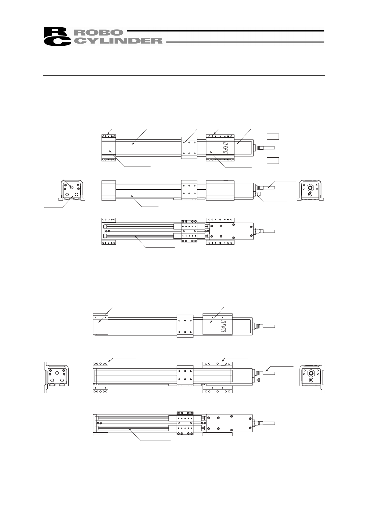
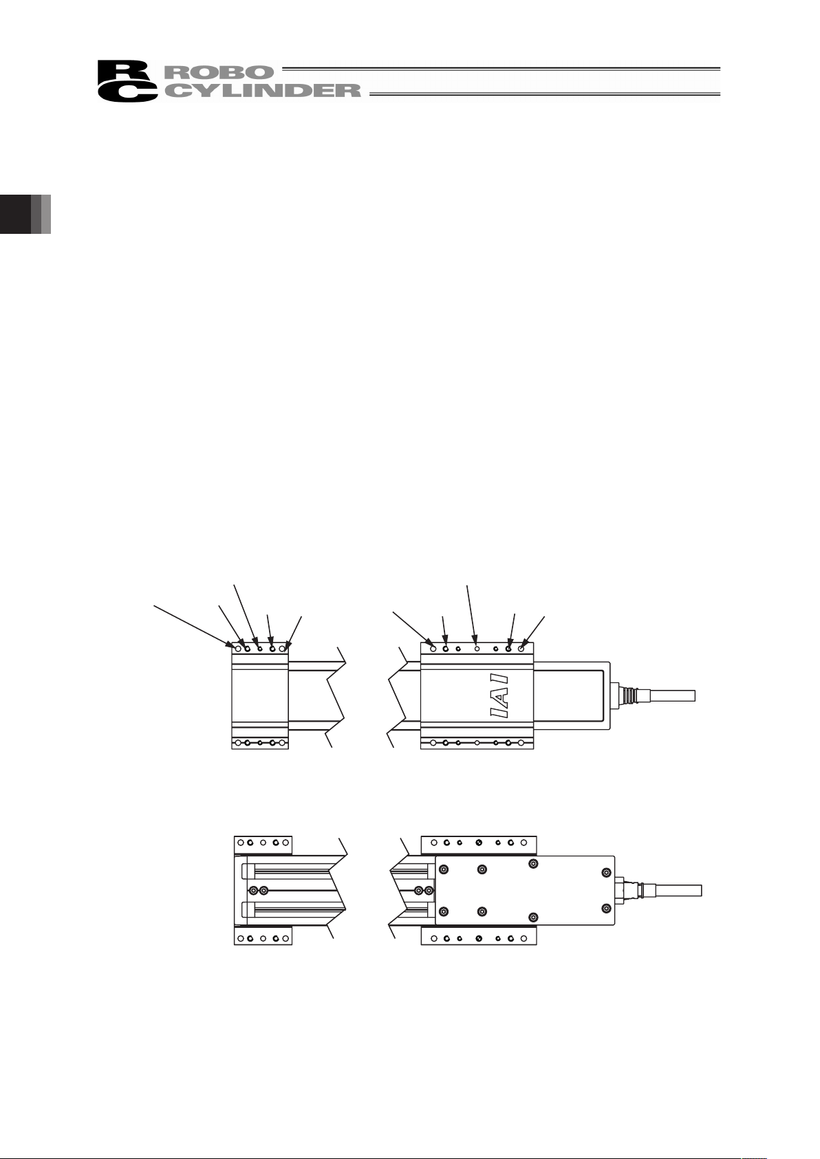
[Standard Type]
Use the bracket to install the unit horizontally with the openings facing the bottom.
Bracket (Front) Base Slider Bracket (Rear) Motor Cover
Actuator Cable
Air Inlet
φ6 for Air Purge
Bolt Cover (Front)
Side Cover
Front Cover
Grommet
Right
Left
Opening (with seal)
Bolt Cover (Rear)
䎃
䎃
䎃
䎃
䎃
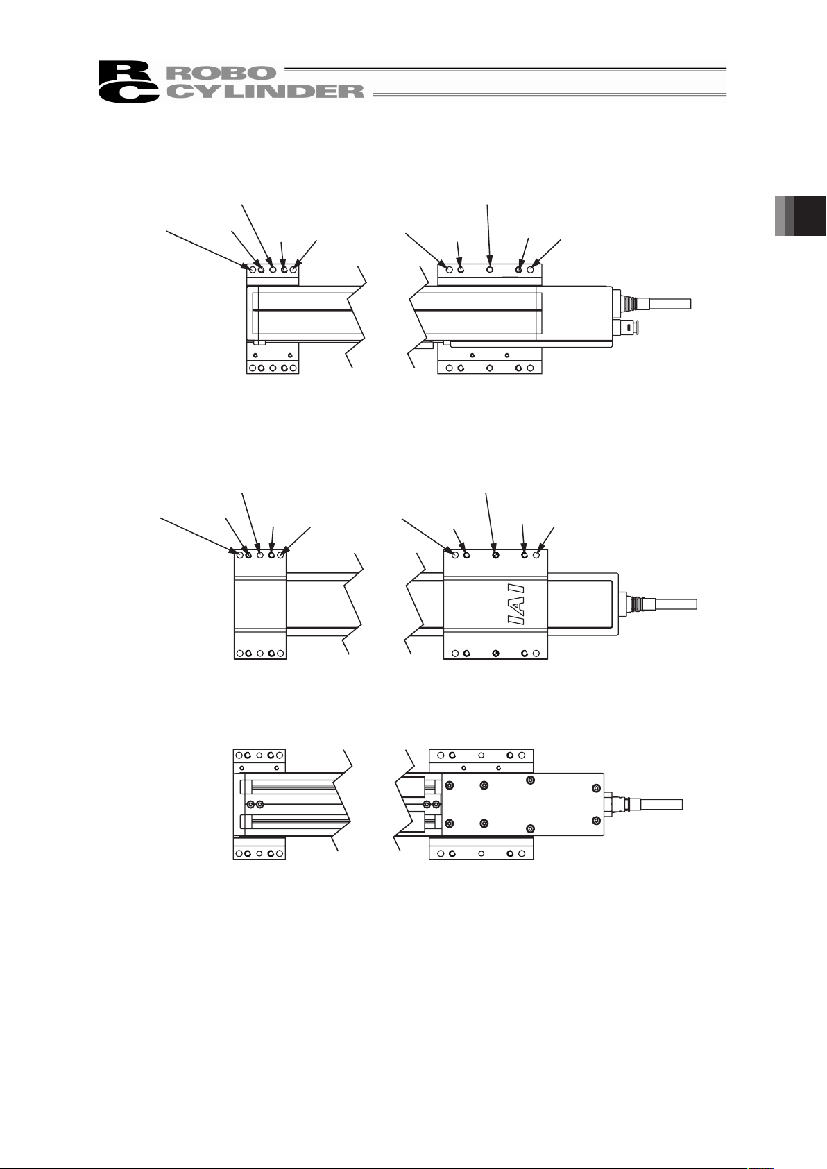
[Wall-hang Type]
Install the actuator horizontally on the wall with the opening on the bottom and with using the bracket.
Bolt Cover (Front) Bolt Cover (Rear)
Right
Left
Bracket (Front) Bracket (Rear)
Actuator Cable
Opening (with seal)
䎃
䎃
䎃
Page 16
10
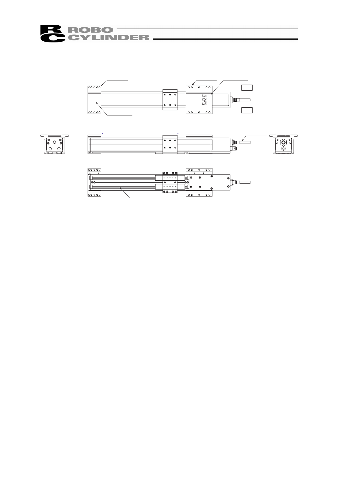
[Ceiling Type]
Install the actuator handing on the ceiling with the opening on the bottom and with using the bracket.
Bracket (Front) Bolt Cover (Rear)
Right
Left
Bolt Cover (Front)
Bracket (Rear)
Opening (with seal)
Actuator Cable
䎃
䎃
Page 17
11
1. Specifications Check
1.1 Product Check
The standard configuration of this product is comprised of the following parts.
See the component list for the details of the enclosed components. If you find any fault or missing parts,
contact your local IAI distributor.
1.1.1 Parts
No. Part Name Model Quantity Remarks
1 Main Body
Refer to “How to read the
model plate” and “How to read
the model No.”.
1
Accessories
2
Motor • Encoder Cable
(Note 1)
1
3 First Step Guide 1
4 Instruction Manual (DVD) 1
5 Safety Guide 1
Note 1 The motor • encoder cables differ between the standard model and robot cable.
[Refer to 1.4 Motor • Encoder Cables.]
1.1.2 Instruction Manuals related to this product, which are contained in the DVD.
Shown below is a list of the instruction manuals for the controllers related to this product which is
recorded in Instruction Manual (DVD).
No. Name Manual No.
1 PCON-CA Controller Instruction Manual ME0289
2
RC PC Software
RCM-101-MW/RCM-101-USB Instruction Manual
ME0155
3 Touch Panel Teaching CON-PTA/PDA/PGA Instruction Manual ME0295
1.1.3 How to read the model plate
Model
Serial number
MODEL RCP4W-SA5C-I-35P-10-500-P3-M-A1
SERIAL No.000061911 MADE IN JAPAN
1. Specications Check
Page 18

1. Specications Check
12
1.1.4 How to read the model No.
RCP4W – SA5C – I – 35P – 10 – 500 – P3 – M – A1 – **
Note 1 Identification for IAI use only : It may be displayed for IAI use. It is not a code to show the
model type.
Identification for IAI use only
(
Note1
)
<Option>
A1 : Cable exit to the left side
A3 : Cable exit to the right side
GE : Food grade grease indicated
NM : Reversed home type
TFL : Wall mount to the left type
TFR : Wall mount to the right type
HFL : Ceiling mount to the left type
HFR : Ceiling mount to the right type
<Cable Length>
N : No cable
P : 1m
S : 3m
M : 5m
XƑƑ : Specified length
RƑƑ : Robot cable
<Applicable Controller>
P3: PCON-CA
<Stroke>
[Refer to 1.2 Specification]
Series Name
<Type>
SA5C, SA6C
SA7C
<Encoder Type>
I: Incremental
<Motor Type>
35P: 35Ƒ
42P: 42Ƒ
56P: 56Ƒ
<Lead>
5: 5mm
6: 6mm
8: 8mm
10: 10mm
12: 12mm
16: 16mm
Page 19
13
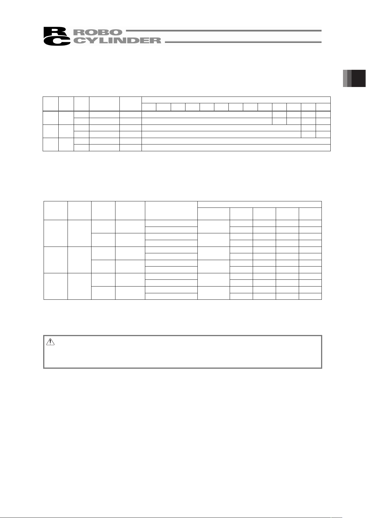
1.2 Specification
[1] Speed
Restriction on Speed (Unit: mm/s)
Stroke [mm]
Size
Motor
Type
Lead
[mm]
Horizontal/
Vertical
Minimum
speed
100 150 200 250 300 350 400 450 500 550 600 650 700
5 Horizontal 6.25 165 – – – –
SA5C 35P
10 Horizontal 12.5 330 – – – –
6 Horizontal 7.5 200 – –
SA6C 42P
12 Horizontal 15 400 – –
8 Horizontal 10 265
SA7C 56P
16 Horizontal 20 530
[2] Maximum Acceleration and Transportable Weight
When the transported weight is low, the acceleration/deceleration speed can be increased.
Installation with holding only one side on the bracket (rear) on the motor end of the actuator is
restricted to the models of 150 or less for the stroke type.
Transportable Weight for Each Acceleration [kg]
Type
Motor
Type
Lead
[mm]
Horizontal/
Vertical
Two-sided Fix
*1
/
One-sided Fix
*2
Speed
[mm/s]
0.3G 0.4G 0.5G 0.6G
Two-sided Fix 10 8 6 4
5 Horizontal
One-sided Fix
165
2 1.5 1.2 1
Two-sided Fix 5 4 3 2
SA5C 35P
10 Horizontal
One-sided Fix
330
1.5 1 0.7 0.5
Two-sided Fix 15 12 9 6
6 Horizontal
One-sided Fix
200
4.5 3.5 3 2.5
Two-sided Fix 7.5 5.5 4 3
SA6C 42P
12 Horizontal
One-sided Fix
400
3 2.5 2 1.5
Two-sided Fix 20 16 12 8
8 Horizontal
One-sided Fix
265
7 6 5 4
Two-sided Fix 10 8 6 4
SA7C 56P
16 Horizontal
One-sided Fix
530
4.5 4 3.5 3
*1 Two-sided Fix : Unit is held on the bracket (front) and bracket (rear).
*2 One-sided Fix : Hold on bracket (rear) (only for the types with stroke 150mm or less), holding only
on the bracket (front) is prohibited.
Caution: Do not attempt to establish the settings for the acceleration/deceleration above the
allowable range. It may cause vibration, malfunction or shortened life. Setting of
acceleration/deceleration above the ratings may cause creeping or slippage of the
coupling.
1. Specications Check
Page 20
1. Specications Check
14
[3] Driving System • Position Detector
Ball Screw Type
Type Motor Type
Lead
[mm]
No. of Encoder
Pulses
Type Diameter Accuracy
5
SA5C 35P
10
Rolled
I8mm
C10
6
SA6C 42P
12
Rolled
I10mm
C10
8
SA7C 56P
16
800
Rolled
I12mm
C10
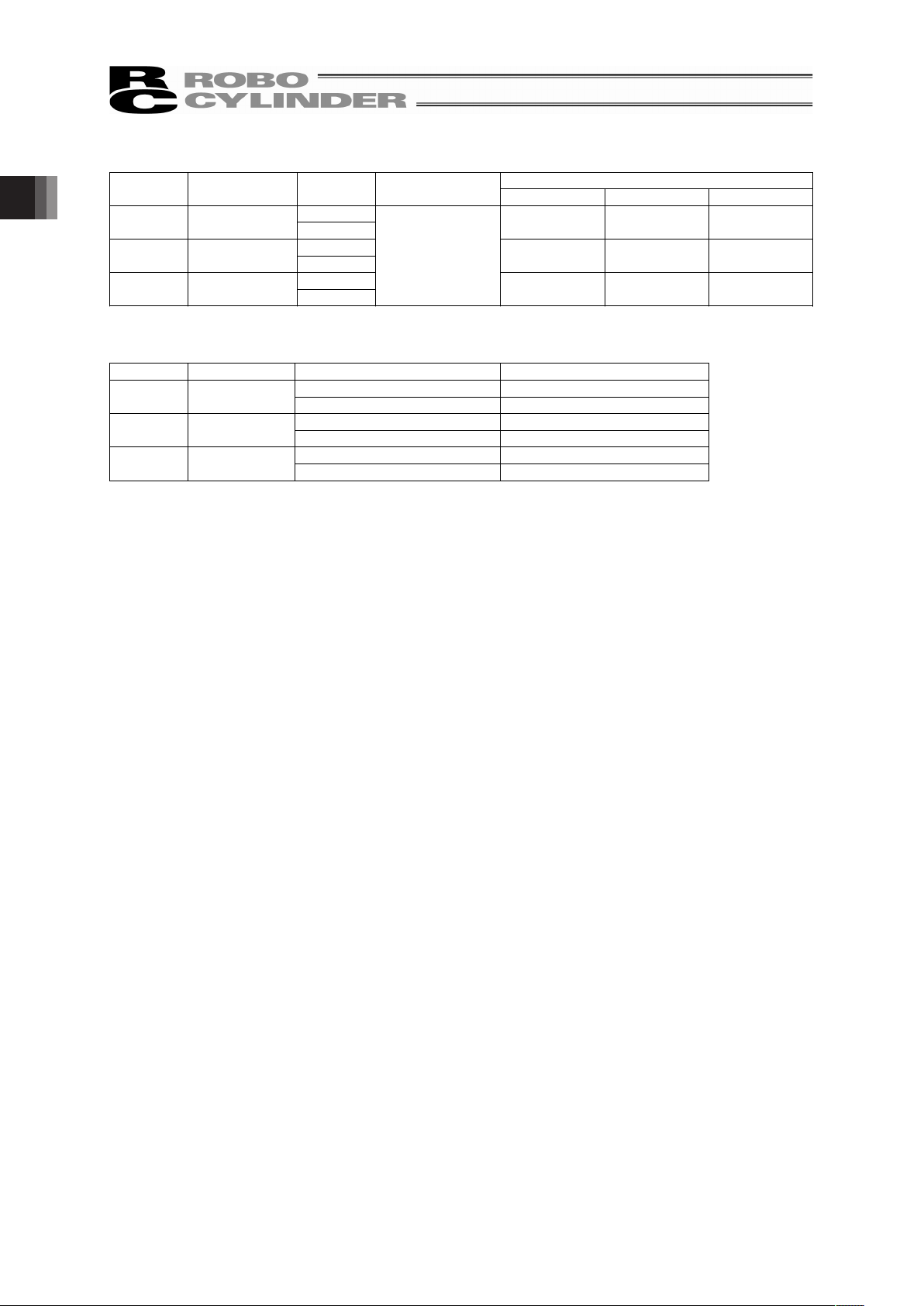
[4] Positioning Accuracy
Type Lead [mm] Item Performance
Positioning Repeatability ±0.02mm
SA5C 5, 10
Lost Motion 0.1mm or less
Positioning Repeatability ±0.02mm
SA6C 6, 12
Lost Motion 0.1mm or less
Positioning Repeatability ±0.02mm
SA7C 8, 16
Lost Motion 0.1mm or less
It is the accuracy when product is shipped out from the factory. It does not include the consideration of
time-dependent change.
Page 21
15
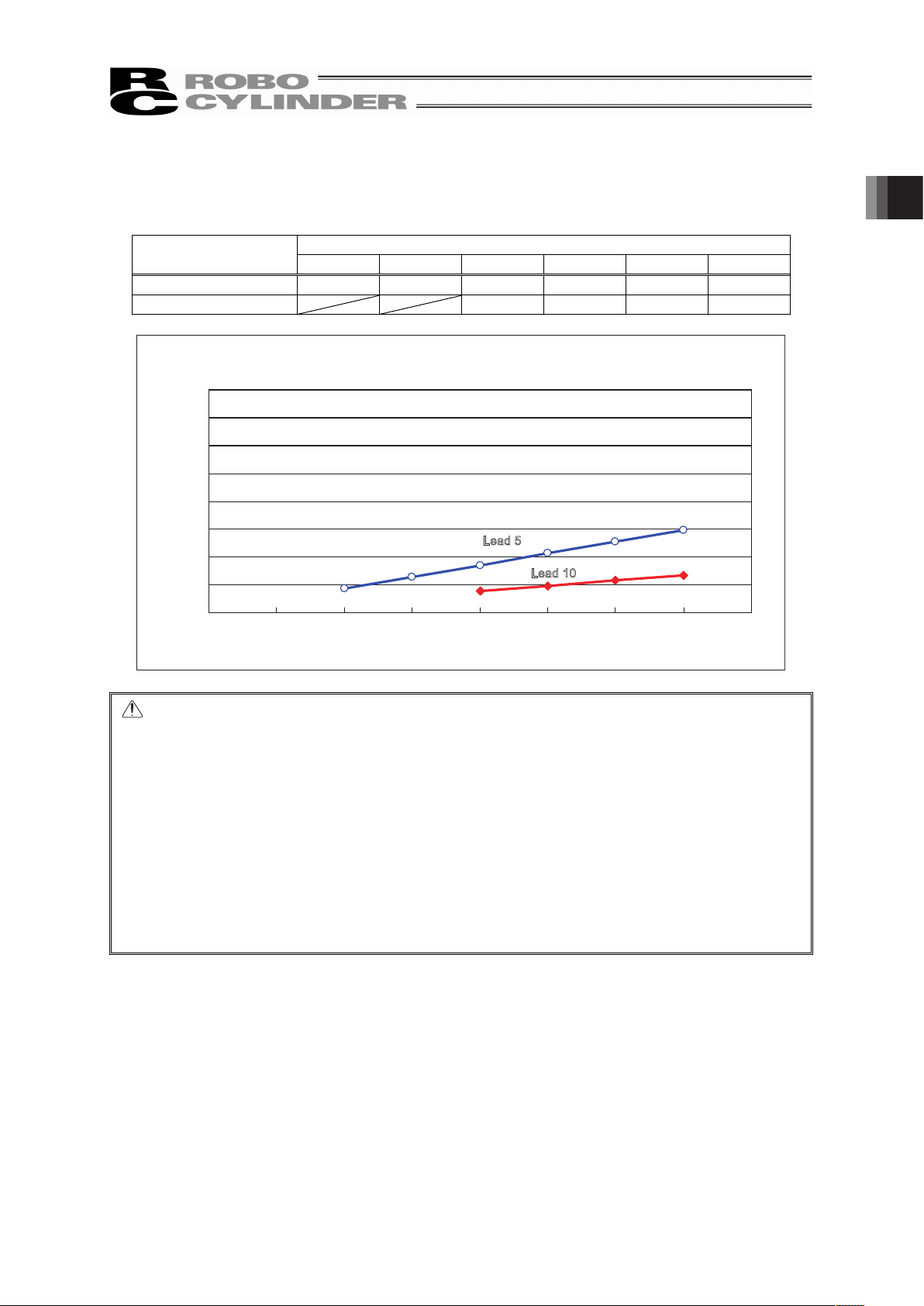
[5] Relation between Current Limit and Pressing Force
x SA5C
Pressing Force [N]
Current Limit Value [%]
Ball Screw Lead
[mm]
20 30 40 50 60 70
5 42.3 63.4 84.5 105.6 126.8 147.9
10 38.2 47.8 57.3 66.9
SA5C Current Limit Value and Pressing Force
0
50
100
150
200
250
300
350
400
0% 10% 20% 30% 40% 50% 60% 70% 80%
Current Limit Value [%]
Pressing Force [N]
Lead 5
Lead 10
Caution: (1) The relation of the current limit and the pressing force is a reference assuming
when the speed is 20mm/s.
(2) There will be a little variance in the actual pressing force. If the value of current
limit is small, the variance for the pressing force becomes big.
(3) Use the product with the current limit within the range specified in the graph. If
used below 20%, the pressing force would not be stable. An operation may not
be made in some cases. An operation cannot be made also when it is beyond
70%. If use in such a condition, it may extremely shorten the product life by the
degradation of insulator in the motor coil due to heat generation.
(4) When the approaching speed (setting in the position table) to the pressing start
position is 20mm/s or less, the pressing operation will be made with the
approaching speed. In this case, also, the pressing force would not be stable. In
such cased, check in advance that the actuator can be used with no problem
before start using.
1. Specications Check
Page 22
1. Specications Check
16
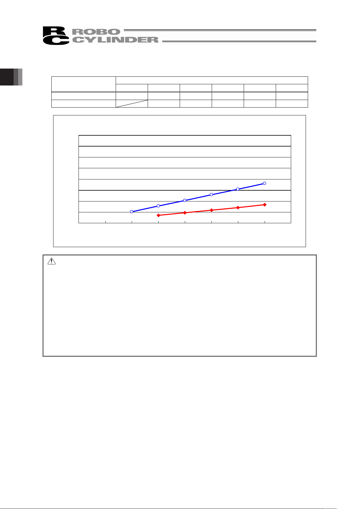
x SA6C
Pressing Force [N]
Current Limit Value [%]
Ball Screw Lead
[mm]
20 30 40 50 60 70
6 51.3 76.9 102.6 128.2 153.9 179.5
12 35.5 47.3 59.1 71.0 82.8
SA6C
Current Limit Value and Pressing Force
0
50
100
150
200
250
300
350
400
0% 10% 20% 30% 40% 50% 60% 70% 80%
Current Limit Value [%]
Pressing Force [N]
Lead 6
Lead 12
Caution: (1) The relation of the current limit and the pressing force is a reference assuming
when the speed is 20mm/s.
(2) There will be a little variance in the actual pressing force. If the value of current
limit is small, the variance for the pressing force becomes big.
(3) Use the product with the current limit within the range specified in the graph. If
used below 20%, the pressing force would not be stable. An operation may not
be made in some cases. An operation cannot be made also when it is beyond
70%. If use in such a condition, it may extremely shorten the product life by the
degradation of insulator in the motor coil due to heat generation.
(4) When the approaching speed (setting in the position table) to the pressing start
position is 20mm/s or less, the pressing operation will be made with the
approaching speed. In this case, also, the pressing force would not be stable. In
such cased, check in advance that the actuator can be used with no problem
before start using.
Page 23
17
x SA7C
Pressing Force [N]
Current Limit Value [%]
Ball Screw Lead
[mm]
20 30 40 50 60 70
8 96.5 144.8 193.1 241.4 289.6 337.9
16 46.3 69.4 92.5 115.6 138.8 161.9
0
50
100
150
200
250
300
350
400
0% 10% 20% 30% 40% 50% 60% 70% 80%
SA7C
Current Limit Value and Pressing Force
Current Limit Value [%]
Pressing Force [N]
Lead 8
Lead 16
Caution: (1) The relation of the current limit and the pressing force is a reference assuming
when the speed is 20mm/s.
(2) There will be a little variance in the actual pressing force. If the value of current
limit is small, the variance for the pressing force becomes big.
(3) Use the product with the current limit within the range specified in the graph. If
used below 20%, the pressing force would not be stable. An operation may not
be made in some cases. An operation cannot be made also when it is beyond
70%. If use in such a condition, it may extremely shorten the product life by the
degradation of insulator in the motor coil due to heat generation.
(4) When the approaching speed (setting in the position table) to the pressing start
position is 20mm/s or less, the pressing operation will be made with the
approaching speed. In this case, also, the pressing force would not be stable. In
such cased, check in advance that the actuator can be used with no problem
before start using.
1. Specications Check
Page 24

1. Specications Check
18
[6] Duty Ratio in Continuous Operation
Continuous operation is available with the duty ratio 100%.
Duty ratio is the rate of operation expressed in % that presents the time of the actuator being
operated in 1 cycle of operation.
[7] Protection Class
If air purge is conducted = IP65
[Refer to 2.4 Air Purge for the details.]
Page 25
19
1.3 Option
1.3.1 Cable Exit Direction (Model: A1, A2)
Right side
Left side
Standard type
Right side
Left side
Cable Exit to the Left Side (AI) Cable Exit to the Right Side (AI)
Right side
Left side
1.3.2 Food Grade Grease Indicated(Model: GE)
Food grade grease (Medallion FM Grease No. 1) is to be applied.
1.3.3 Reversed-home Type (Model: NM)
For the standard type, the home position is set on the motor end. The home position for Home
Reversed Type is on the opposite side (front cover side) of the motor. This is the type that the operation
direction can be matched to the coordinates of the equipment that the actuator is to be installed.
[Refer to 5. External Dimensions for the home position of Standard Type and Home Reversed Type.]
Caution: The home position is already set in the factory before delivered out. If changed to the
reversed type is required after the unit is delivered, it is necessary to return the unit to
our factory for the setting change. Contact our sales office or agent near you.
1.3.4 Types of Installation (Model: TFL, TFR, HFL, HFR)
Left
side
Right
side
Standard type
Left
side
Right
side
Wall mount
to the left type (TFL)
Left
side
Right
side
Ceiling mount
to the right type (HFR)
Wall mount
to the right type (TFR)
Left
side
Right
side
Left
side
Right
side
Ceiling mount
to the left type (HFL)
View from Side of Motor
1. Specications Check
Page 26
1. Specications Check
20
1.4 Motor • Encoder Cables
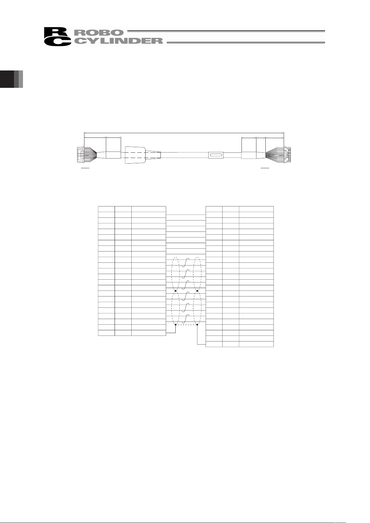
1.4.1 Motor • Encoder Integrated Cables
CB-CA-MPAƑƑƑ
Contact : 1827570-2
CN2
CN1
(25) (15) (30)
L
Connector : 1-1827863-1
SPND-002T-C0.5 (AWG26)
SPND-001T-C0.5 (AWG22)
Connector : PADP-24V-1-S
Contact
(25)(30)
1-1827863-1(AMP)
23
22
21
4
3
9
10
20
19
17
18
B5
A5
A11
B11
B10
A10
A9
B9
B8
A8
B6
A6
A7
B7
B4
A4
A3
B3
B2
A2
16
13
12
11
8
6
7
2
1
5
14
15
24
A1
B1
CN1
CN2
BL(AWG22/19)
OR(AWG22/19)
GN(AWG22/19)
BR(AWG22/19)
GY(AWG22/19)
RD(AWG22/19)
BK(AWG26)
YW(AWG26)
BL(AWG26)
OR(AWG26)
GN(AWG26)
BR(AWG26)
GY(AWG26)
RD(AWG26)
BL(AWG26)
OR(AWG26)
GN(AWG26)
GY(AWG26)
RD(AWG26)
BL(AWG22/19)
OR(AWG22/19)
GN(AWG22/19)
BR(AWG22/19)
GY(AWG22/19)
RD(AWG22/19)
BK(AWG26)
YW(AWG26)
BL(AWG26)
OR(AWG26)
GN(AWG26)
BR(AWG26)
GY(AWG26)
RD(AWG26)
BL(AWG26)
OR(AWG26)
GN(AWG26)
BR(AWG26) BR(AWG26)
GY(AWG26)
RD(AWG26)
―
Color
Pin No. Pin No.
Color
―
―
―
BK
BK
PADP-24V-1-S(JST)
Symbol
―
―
―
FG
―
GND
VCC
VPS
LS_GND
BK-/LS-
BK+/LS+
B+/Z+
B-/Z-
A+/B+
A-/B-
-/A-
-/A+
LS-/BK-
LS+/BK+
φ_B/-
VMM/-
φB/-
φ_A/W
VMM/V
φA/U
GND
VCC
VPS
LS_GND
BK-/LS-
BK+/LS+
B+/Z+
B-/Z-
A+/B+
A-/B-
-/A-
-/A+
LS-/BK-
LS+/BK+
φ_B/-
VMM/-
φB/-
φ_A/W
VMM/V
φA/U
Symbol
FG
Connection diagram
Page 27
21
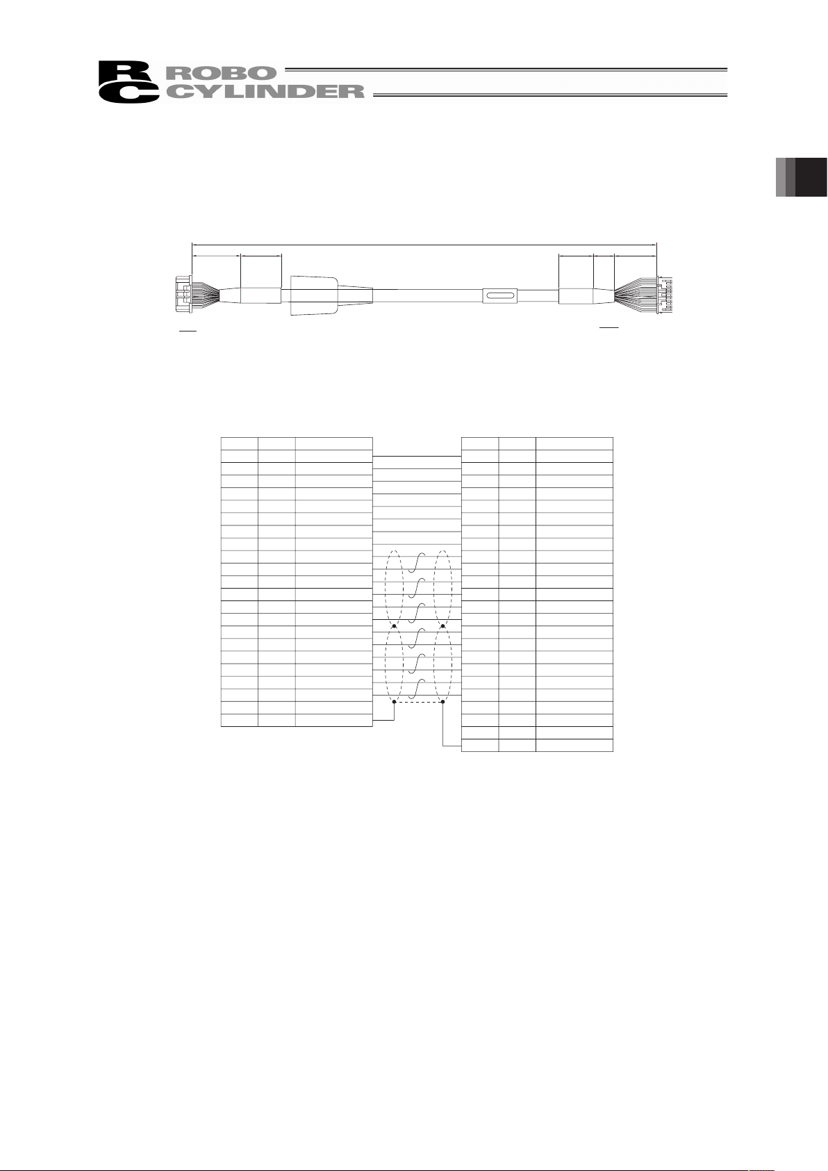
1.4.2 Motor • Encoder Integrated Cables Robot Cable
CB-CA-MPAƑƑƑ-RB
SPND-002T-C0.5 (AWG26)
SPND-001T-C0.5 (AWG22)
Contact :
1827570-2
Connector :
PADP-24V-1-S
CN2
CN1
(25) (15) (30)
L
Connector :
1-1827863-1
Contact
(25)
(30)
Symbol
PADP-24V-1-S (
JST)
Pin No.
―
CN2
CN1
B1
A1
24
15
14
5
1
2
7
6
8
11
12
13
16
A2
B2
B3
A3
A4
B4
B7
A7
A6
B6
A8
B8
B9
A9
A10
B10
B11
A11
A5
B5
18
17
19
20
10
9
3
4
21
22
23
1-1827863-1(AMP)
OR
(AWG25)
GY
(AWG25)
WT
(AWG25)
YW
(AWG25)
RD
(AWG25)
GN
(AWG25)
BK(AWG25)
BR
(AWG25)
BK
(AWG25)
BR
(AWG25)
GN
(AWG25)
RD
(AWG25)
WT
(AWG25)
YW
(AWG25)
Shield
―
―
―
YW
(AWG25)
WT
(AWG25)
RD
(AWG25)
GN
(AWG25)
BR
AWG25)
BK
(AWG25)
BR
(AWG25)
BK
(AWG25)
GN
(AWG25)
RD
(AWG25)
YW
(AWG25)
WT
(AWG25)
GY
(AWG25)
OR
(AWG25)
Color
Symbol
Pin No.
Color
Connection diagram
―
GND
VCC
VPS
LS_GND
BK-/LS-
BK+/LS+
B+/Z+
B-/Z-
A+/B+
A-/B-
-/A-
-/A+
LS-/BK-
LS+/BK+
φ_B/-
VMM/-
φB/-
φ_A/W
VMM/V
φA/U
FG
―
―
―
FG
GND
VCC
VPS
LS_GND
BK-/LS-
BK+/LS+
B+/Z+
B-/Z-
A+/B+
A-/B-
-/A-
-/A+
LS-/BK-
LS+/BK+
φ_B/-
VMM/-
φB/-
φ_A/W
VMM/V
φA/U
BK(AWG22/19)
WT(AWG22/19)
BR(AWG22/19)
GN(AWG22/19)
YW(AWG22/19)
RD(AWG22/19)
BK(AWG22/19)
WT(AWG22/19)
BR(AWG22/19)
GN(AWG22/19)
YW(AWG22/19)
RD(AWG22/19)
1. Specications Check
Page 28

2. Installation
22
2. Installation
2.1 Transportation
[1] Handling of the Robot
Unless otherwise specified, the actuators are wrapped individually when the product is shipped out.
(1) Handling of the Packed Product
x Do not damage or drop. The package is not applied with any special treatment that enables it to
resist an impact caused by a drop or crash.
x An operator should never attempt to carry a heavy package on their own. Also, use an appropriate
way for transportation.
x If the shipping box is to be left standing, it should be in a horizontal position. Follow the instruction if
there is any for the packaging condition.
x Do not step or sit on the package.
x Do not put any load that may cause a deformation or breakage of the package.
(2) Handling after Unpackaged
x Do not carry the actuator by holding the cable, or do not move it by pulling the cable.
x When transporting the actuator main unit, hold the base or bracket part.
x Do not hit or drop the product while carrying.
x Do not give any excessive force to any of the sections in the actuator.
Page 29

23
[2] Handling of the Multi-Axes Type
This is the case that this product is delivered with other actuators being combined. Multi-axes type will
be delivered in a package with an outer case fixed to a wooden base. Sliders are fixed so they would
not accidently move while in transportation. The end of the actuator is also fixed to avoid it swinging by
external vibration.
(1) Handling of the Packed Product
x Do not damage or drop. The package is not applied with any special treatment that enables it to
resist an impact caused by a drop or crash.
x An operator should never attempt to carry a heavy package on their own. Also, use an appropriate
way for transportation.
x When suspending the package using ropes, pass the ropes from underneath the reinforcement
frames at the bottom of the base. When lifting with a forklift, also place the forks underneath the
base.
x Do not apply an impact on the package or let it bounce when putting it down.
x Do not step or sit on the package.
x Do not put any load that may cause a deformation or breakage of the package.
(2) Handling after Unpackaged
x Secure the sliders to prevent sudden movement during transport.
x Appropriately fix the tip of the actuators if it is overhanging so it would not widely shake with external
vibration. If the actuator assembly is transported without the ends being secured, do not apply an
impact of 0.3G or more.
x In the case that the actuator needs to be carried up with ropes or another method, be sure to use an
appropriate cushioning to avoid the robot being deformed or put on an excessive pressure. And also,
be sure to keep the robot in a stable and horizontal posture. Make a tool to utilize the attachment
holes and tapped holes on the actuator and attach it if necessary.
x Do not attempt to apply load to the actuator or connector box. Also, avoid the cables being pinched
or caused an excessive deformation.
[3] Handling of the Robot Mounted on Mechanical Equipment (System)
The following are the cautions for when transporting the actuators installed in the machinery equipment
(system) in the whole system.
x Affix the slider so they would not move while transporting.
x Appropriately fix the tip of the actuators if it is overhanging so it would not widely shake with external
vibration. If the actuator assembly is transported without the ends being secured, do not apply an
impact of 0.3G or more.
x Do not attempt to apply load to actuators or connector box when hanging the machinery equipment
(system) with tools such as a rope. Also, avoid the cables being pinched or caused an excessive
deformation.
2. Installation
Page 30

2. Installation
24
2.2 Installation and Storage • Preservation Environment
[1] Installation Environment
Do not use this product in the following environments.
Also make sure to keep enough work space necessary for maintenance.
x Location exposed to radiant heat from a huge heat source such as the heat treatment
x Location where the surrounding air temperature exceeds the range of 0 to 40qC
x Location where condensation occurs due to abrupt temperature changes
x Location where relative humidity exceeds 85%RH
x The product gains the water-proof performance of IP65 protection structure if an air purge is
conducted.
x Location exposed to direct sunlight
x Location exposed to corrosive gases or combustible gases
x Location exposed to significant amount of dust, salt or iron powder (Outside of an ordinary
assembly plant)
x Location where oil (includes oil mist and cutting fluid) or a chemical is splashed
x Location where the product main body receives vibration or hit impact
When using the product in any of the locations specified below, provide a sufficient shield.
x Place subject to electrostatic noise
x Location where exposed to the influence of strong electric or magnetic field
x Location where exposed to the influence of ultraviolet or radiant rays
[2] Storage • Preservation Environment
x The storage and preservation environment should comply with the same standards as those for the
installation environment. In particular, when the machine is to be stored for a long time, pay close
attention to environmental conditions so that no dew condensation forms.
x Unless specially specified, moisture absorbency protection is not included in the package when the
machine is delivered. In the case that the machine is to be stored and preserved in an environment
where dew condensation is anticipated, take the condensation preventive measures from outside of
the entire package, or directly after opening the package.
x For storage and preservation temperature, the machine withstands temperatures up to 60qC for a
short time, but in the case of the storage and preservation period of 1 month or more, control the
temperature to 50qC or less.
x Storage and preservation should be performed in the horizontal condition. In the case it is stored in
the packaged condition, follow the posture instruction if any displayed on the package.
Page 31

25
2.3 How to Install
Shown below is how to install the actuators to the machinery equipment.
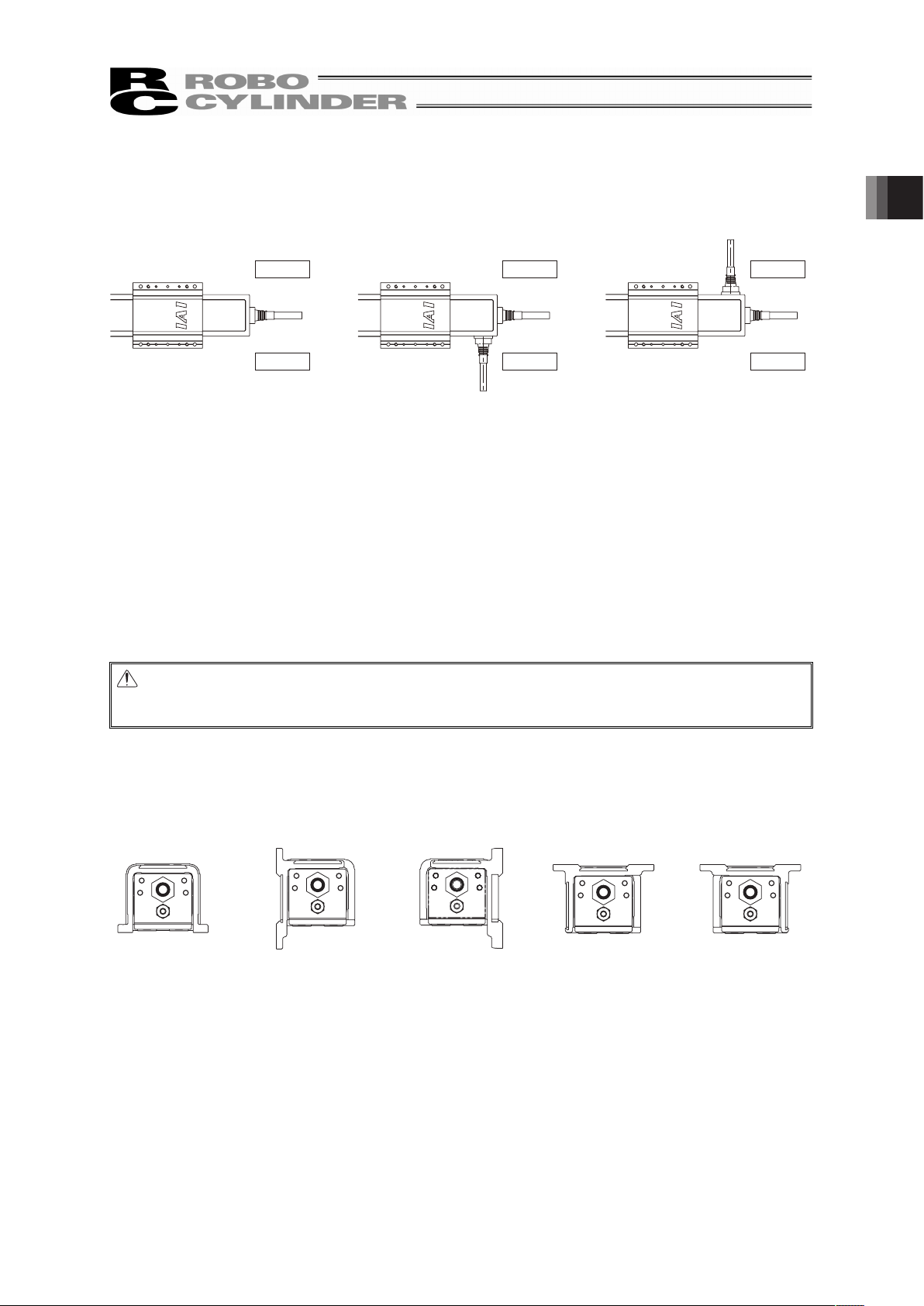
2.3.1 Attachment Orientation
Shown below are the basic concepts for the product attachment.
Pay special attention when deciding how to install the product (Except with custom-order models).
{: Available ×: Not available
Attachment
Orientation
Horizontal
Installation
Vertical
Installation
Wall Mount
Installation
(Note 1)
Ceiling Mount
Installation
(Note 1)
Types of
Installation
Standard Type – Wall-hang Type Ceiling Type
Installation
Availability
{
×
{ {
Note 1 It is necessary to have the dedicated bracket (option). Request should be made at the order.
Attachment Orientation
Horizontal Vertical Wall Mount Ceiling Mount
Caution: The actuator can only be installed in the orientation with the opening on the bottom
side when it is in the wall mount or ceiling mount installation. If installation is conducted
in a way out of indicated, the Protection Class cannot be guaranteed.
2. Installation
Page 32
2. Installation
26
2.3.2 Installation
[1] Installation of Main Unit
x The surface to mount the actuator main unit should be a machined surface or a plane that
possesses an equivalent accuracy and the flatness should be within 0.1mm. Also, the platform
should have a structure stiff enough to install the unit so it would not generate vibration or other
abnormality.
x Also consider enough space necessary for maintenance work such as actuator replacement and
inspection.
x There are datum surfaces for installation on the side and bottom of the actuator bracket.
The flatness of the table operation differs for the total length stroke of each actuator. [Refer to (1)
Datum surface in this section]
x On the bracket of the actuator, there are tapped holes and through holes for installation and reamed
holes for positioning. Please refer to the appearance drawings for the details of the positions and
dimensions. [Refer to 5. External Dimensions]
Utilize the reamed holes when the repeatability in attachment is required after detaching. However,
when small tunings such as the perpendicularity is required, consider such things like to use one
reamed hole.
x The actuator can be held only on the bracket (rear) on the motor end. However, the stroke type is
restricted to those of 150 or less. Also, the static allowable load moment, dynamic allowable load
moment and overhang length are different from when fixed with the brackets on two sides. [Refer to
[2] Load Attachment in this section]
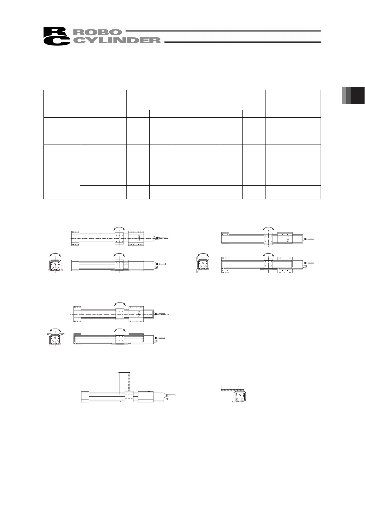
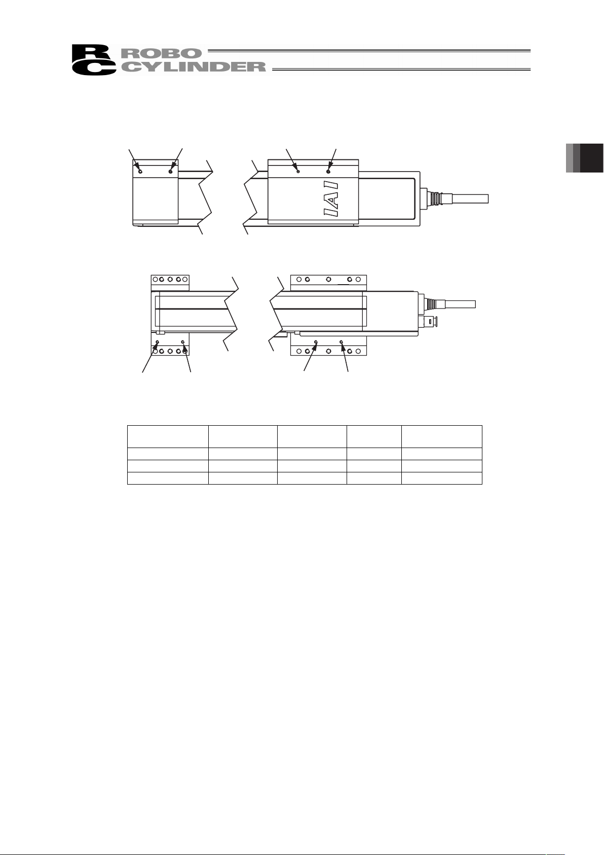
٧ Standard Type
ڏ Top
Through
hole
Through
hole
Through
hole
Tapped
hole
Tapped
hole
Tapped
hole
Through
hole
Tapped
hole
Bracket (Front) Bracket (Rear)
Reamed hole
(Through)
Reamed hole
(Through)
ڏ Bottom
Bracket (Front) Bracket (Rear)
Page 33
27
٧ Wall-hang Type
ڏSide
Through
hole
Through
hole
Through
hole
Tapped
hole
Tapped
hole
Tapped
hole
Through
hole
Tapped
hole
Bracket (Front) Bracket (Rear)
Reamed hole
(Through)
Reamed hole
(Through)
٧ Ceiling Type (Top)
ڏTop
Through
hole
Through
hole
Through
hole
Tapped
hole
Tapped
hole
Tapped
hole
Through
hole
Tapped
hole
Bracket (Front) Bracket (Rear)
Reamed hole
(Through)
Reamed hole
(Through)
ڏ Bottom
Bracket (Front) Bracket (Rear)
2. Installation
Page 34
2. Installation
28
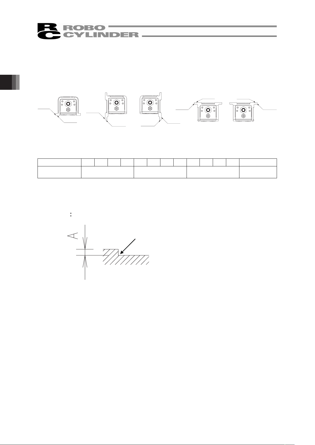
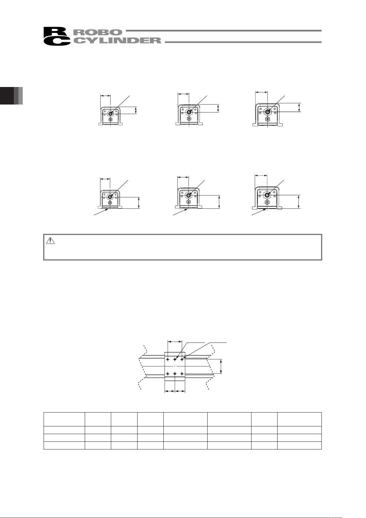
(1) Datum surface
There are datum surfaces for attachment on the bracket.
The flatness of the table operation differs for the stroke type of each actuator.
Left
side
Right
side
Wall mount to the left type
Datum
surface
Datum
surface
Left
side
Right
side
Wall mount to the right type
Datum
surface
Datum
surface
Left
side
Right
side
Standard type
Datum
surface
Datum
surface
Left
side
Right
side
Ceiling mount to the right type
Datum
surface
Datum
surface
Left
side
Right
side
Ceiling mount to the left type
Datum
surface
Datum
surface
Positions of Datum Surfaces (View from Shaft End on Motor Side)
Stroke 100 150 200 250 300 350 400 450 500 550 600 650 700
Traveling
Parallelism
(Note 1)
0.10mm or less 0.12mm or less 0.15mm or less 0.18mm or less
Note 1: The values are those at temperature 20qC. It is the accuracy of travelling against the datum
surface.
(Reference) Shown below is the section view of the machined area for the attachment surface when
mounting using the datum surface.
A䰆 1.5mm or more
R0.3 or less
䎃
䎃
Page 35
29
(2) Mounting method 1 (When Utilizing the Tapped Holes)
Follow the table below for the torque to tighten the attachment screws.
Standard Type
Tightening Torque [N•m]
Actuator Type
Tapping
Diameter
In the case that steel is used for the
bolt seating surface:
In the case that aluminum is used
for the bolt seating surface:
SA5C M4 3.59 1.76
SA6C/SA7C M5 7.27 3.42
Wall-hang Type • Ceiling Type
Tightening Torque [N•m]
Actuator Type
Tapping
Diameter
In the case that steel is used for the
bolt seating surface:
In the case that aluminum is used
for the bolt seating surface:
SA5C/SA6C/SA7C M5 7.27 3.42
Mounting screw
x It is recommended to use high-tensile bolts with ISO-10.9 or more.
x The length of thread engagement should be 1.8 times more than the nominal diameter.
Caution: Pay attention to the bolt length. If a bolt with inappropriate length is used, damage on
tapped holes or accident or failure due to insufficient strength on the actuator
attachment.
2. Installation
Page 36

2. Installation
30
(3) Mounting method 2 (When Utilizing the Through Holes)
Follow the table below for the torque to tighten the attachment screws.
Standard Type
Actuator Type Mounting Holes Mounting Screw Tightening Torque [N•m]
SA5C
I4.5 through hole
M4 1.76
SA6C/SA7C
I5.5 through hole
M5 3.42
Wall-hang Type • Ceiling Type
Actuator Type Mounting Holes Mounting Screw Tightening Torque [N•m]
SA5C/SA6C/SA7C
I5.5 through hole
M5 3.42
Mounting screw
x It is recommended to use high-tensile bolts with ISO-10.9 or more.
x Make sure to have the effective length of screw engagement described below or more for the
tightening of a bolt and a female screw.
When female screw is on steel ĺ thread length same as nominal diameter
When female screw is on aluminum ĺ 1.8 times of nominal diameter
Caution: x Pay attention when selecting screws. If a bolt other than those of the instruction is
used, damage on tapped holes or unexpected accident or failure due to insufficient
strength on the actuator attachment or interference on the driving area.
x There may be a case that water or oil of the grease drops from the seals on the
openings at the bottom surface.
If the unit is installed as shown below, use it in a way that should be no problem even
if water or oil drops below the actuator. Do not place anything that may cause a
problem if water or oil is dropped on it. Otherwise apply a cover on it.
Water or oil may drop
in this space.
Page 37
31
[2] Load Attachment
Ɣ There is a restriction on the moment and overhang load length when attaching a load to the table.
Allowable load moment and overhang load length
Allowable Static Load
Moment
[N•m]
Allowable Dynamic Load
Moment
[N•m]
Actuator Type
Two-sided Fix
/One-sided Fix
(Note 1)
Ma Mb Mc Ma Mb Mc
Allowable Overhang
Load Length L [mm]
Two-sided Fix 5.9 8.4 13.7 3.4 4.9 8.0
Ma direction 125
Mb, Mc direction 125
SA5C
One-sided Fix 2.9 4.2 6.8 1.7 2.5 4.0
Ma direction 75
Mb, Mc direction 75
Two-sided Fix 8.5 12.2 19.9 4.7 6.7 11.0
Ma direction 150
Mb, Mc direction 150
SA6C
One-sided Fix 4.3 6.1 10.0 2.4 3.4 5.5
Ma direction 90
Mb, Mc direction 90
Two-sided Fix 11.7 16.6 31.8 6.1 8.8 16.8
Ma direction 175
Mb, Mc direction 175
SA7C
One-sided Fix 5.8 8.3 15.9 3.1 4.4 8.4
Ma direction 105
Mb, Mc direction 105
Note 1 One-sided attachment is allowed only with the stroke type of 150 or less.
[Standard type] [Wall-hang Type]
Mb direction
Direction of Moment
Ma directionMc direction
Mb direction
Direction of Moment
Ma directionMc direction
[Ceiling Type]
Mb direction
Direction of Moment
Ma directionMc direction
Allowable overhang direction of Ma direction
L
Overhang
Load Length
L
Overhang Load Length
Allowable overhang direction of Mb and Mc directions
2. Installation
Page 38
2. Installation
32
If installing on the top surface of the slider, for the calculation of Ma and Mc moments, consider the
position indicated with an arrow as the datum point.
35.0
SA5C
40.0
SA6C
47.5
SA7C
22.5
26.0
27.5
Datum point for
moment calculation
Datum point for
moment calculation
Datum point for
moment calculation
If installing on the bottom surface of the slider, for the calculation of Ma and Mc moments, consider
the position indicated with an arrow as the datum point.
35.0
41.0
SA5C
40.0
47.5
SA6C
47.5
53.0
SA7C
Datum point for
moment calculation
Datum point for
moment calculation
Datum point for
moment calculation
Bottom surface of table Bottom surface of table Bottom surface of table
Caution: An operation beyond the allowable moment and overhang load length would not only
generate abnormal noise and vibration, but also may shorten the life of actuator
extremely.
Ɣ There are tapped holes prepared for attachment of a load on the top, side and bottom surfaces of the
slider. Also, there are two reamed holes. Utilize the reamed holes when repeatability in the
attachment after detaching is required. Also, if you require precision in your attachment, such as a
right angle, use the reamed hole to make fine adjustments.
Ɣ Shown below is the detail of the attachment area. Attach a load with the bolts listed in the table
below with the specified tightening torque.
Top Surface of the Slider
B
Reamed
hole
2-E
C C
A
Reamed Hole Pitch Tolerance: A ±0.02
Tapped
hole
4-D
䎃
䎃
Actuator Type A B C D E
Tapping
Diameter
Tightening
Torque [N•m]
SA5C 35 35 25 M4, depth 6
I4H7, depth 4
M4 1.76
SA6C 45 45 30 M5, depth 8
I4H7, depth 5
M5 3.42
SA7C 55 55 35 M5, depth 8
I4H7, depth 5
M5 3.42
䎃
Page 39
33
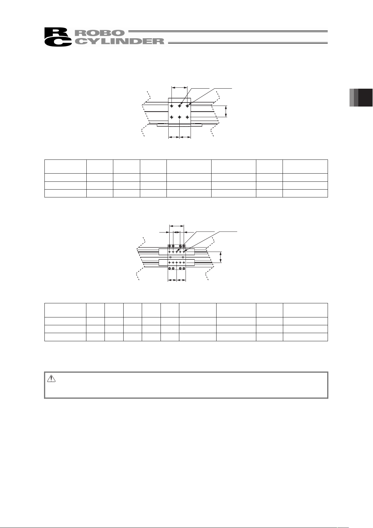
Side Surface of the Slider
B
C C
A
Reamed Hole Pitch Tolerance: A ±0.02
Reamed
hole
2-E
Tapped
hole
4-D
䎃
䎃
Actuator Type A B C D E
Tapping
Diameter
Tightening
Torque [N•m]
SA5C 35 35 25 M4, depth 6
I4H7, depth 4
M4 1.76
SA6C 45 45 30 M5, depth 8
I4H7, depth 5
M5 3.42
SA7C 55 55 35 M5, depth 8
I4H7, depth 5
M5 3.42
䎃
Bottom Surface of the Slider
B
E E
A
Reamed Hole Pitch Tolerance: A ±0.02
CD D
Reamed
hole
2-G
Tapped
hole
8-F
䎃
䎃
Actuator Type A B C D E F G
Tapping
Diameter
Tightening
Torque [N•m]
SA5C 30 40 20 10 25 M3, depth 6
I3H7, depth 5
M3 0.83
SA6C 37 50 25 12.5 30 M3, depth 6
I3H7, depth 5
M3 0.83
SA7C 52 60 30 15 35 M3, depth 6
I3H7, depth 5
M3 0.83
䎃
Mounting screw
x It is recommended to use high-tensile bolts with ISO-10.9 or more.
Caution: Pay attention when selecting screws. If a bolt other than those of the instruction is
used, it may cause damage on tapped holes or unexpected accident or failure due to
insufficient strength on the actuator attachment.
2. Installation
Page 40
2. Installation
34
[3] Installation of Wiring
There are tapped holes prepared for some purposes such as attaching cables on the bracket of the
actuator. See the external dimensions for the details of the position and diameters. [Refer to 5. External
Dimensions]
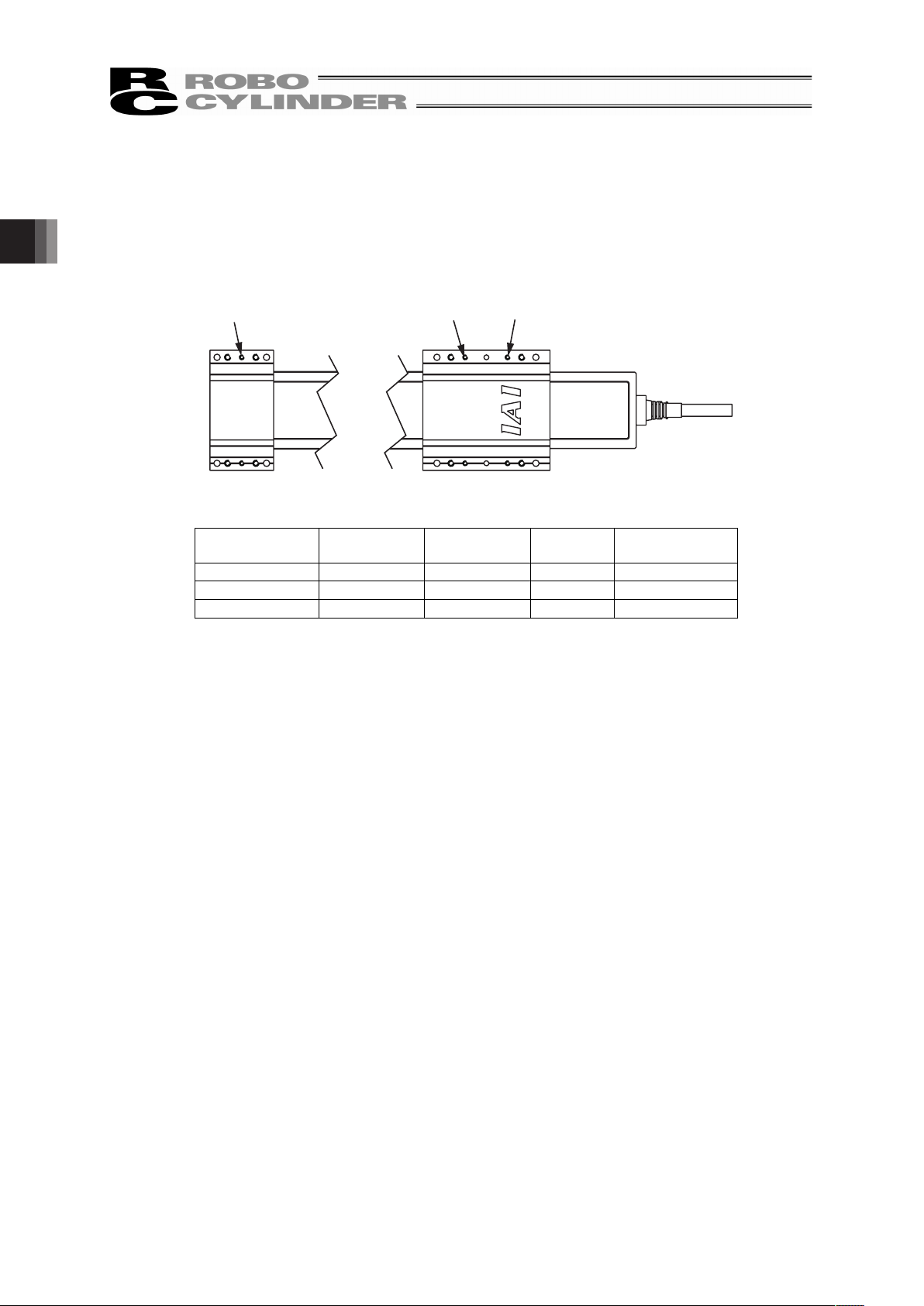
٧ Standard Type
ڏTop
Tapped
hole
Tapped
hole
Tapped
hole
Bracket (Front) Bracket (Rear)
Actuator Type
Bracket (Front)
Tapped Hole
Bracket (Rear)
Tapped Hole
Tapping
Diameter
Tightening Torque
[N•m]
SA5C 2×M3, depth 3 4×M3, depth 7 M3 0.83
SA6C 2×M3, depth 4 4×M3, depth 7 M3 0.83
SA7C 2×M3, depth 4 2×M3, depth 8 M3 0.83
Page 41
35
٧ Wall-hang Type
ڏTop
Tapped
hole
Tapped
hole
Tapped
hole
Tapped
hole
Bracket (Front) Bracket (Rear)
ڏSide
Tapped
hole
Tapped
hole
Tapped
hole
Tapped
hole
Bracket (Front) Bracket (Rear)
Actuator Type
Bracket (Front)
Tapped Hole
Bracket (Rear)
Tapped Hole
Tapping
Diameter
Tightening Torque
[N•m]
SA5C 4×M3, depth 6 4×M3, depth 6 M3 0.83
SA6C 4×M3, depth 6 4×M3, depth 6 M3 0.83
SA7C 4×M3, depth 6 4×M3, depth 6 M3 0.83
2. Installation
Page 42

2. Installation
36
٧ Ceiling Type (Top)
Shown in the figure below is the right ceiling mount type. For the left ceiling mount type, the
positions of tapped holes are on the opposite side when looking in the front view.
ڏBottom
Bracket (Front) Bracket (Rear)
Tapped
hole
Tapped
hole
Tapped
hole
Tapped
hole
Actuator Type
Bracket (Front)
Tapped Hole
Bracket (Rear)
Tapped Hole
Tapping
Diameter
Tightening Torque
[N•m]
SA5C 2×M3, depth 6 2×M3, depth 6 M3 0.83
SA6C 2×M3, depth 6 2×M3, depth 6 M3 0.83
SA7C 2×M3, depth 6 2×M3, depth 6 M3 0.83
Mounting screw
x Make sure to have the length of at least 1.8 times to the bolt diameter below for the effective
length of screw engagement for the tightening of a bolt and a female screw.
Page 43

37
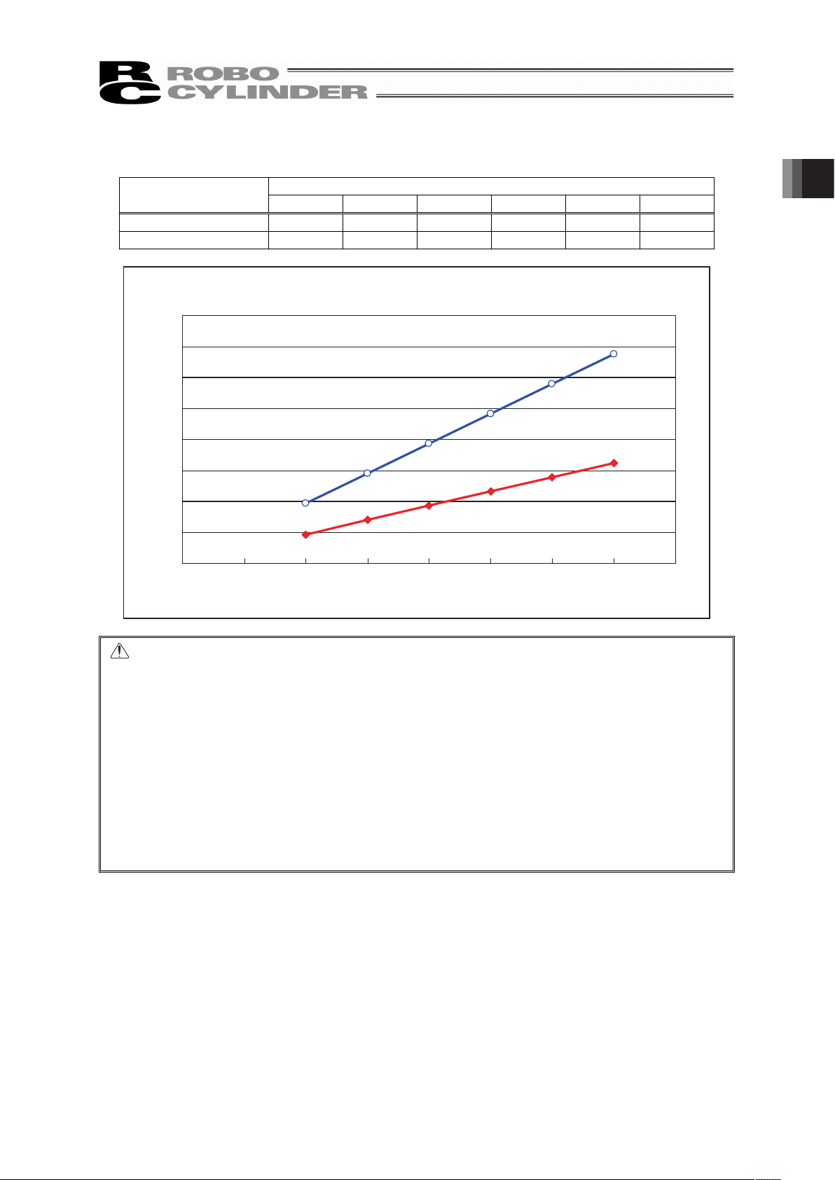
2.4 Air Purge
If using the product in the standard of IP65, it is necessary to conduct air purge to blow clean dry air to
the actuator.
Conduct air purge from the inlet on the side of the motor end of the main unit with air flow 40Nl/min or
more.
Shown below is how the air flow changes with the length of an air tube (O.D. 6mm, I.D. 4mm).
Have an adjustment to obtain air flow of 40Nl/min. by referring to the following graph.
200
180
160
140
120
100
80
60
40
20
0
0 5 10 15 20 25
Pressure :0.3MPa
Pressure :0.2MPa
Pressure :0.1MPa
Air Flow [Nl/min]
Air Tube Length [m]
Air Tube Length vs. Air Flow
2. Installation
Page 44

3. Connection to the Controller
38
3. Connection to the Controller
For the controller, only the dedicated controller manufactured by our company can be used.
Using other controllers may cause a problem such as burning the product, ignition or generating heat.
Use the dedicated cable enclosed in the package when connecting the actuator and the controller.
RCP4W-XX
Actuator cable
Dedicated controller
• PCON-CA
Dedicated connection cable
Motor-encoder cable: CB-CA-MPA□□□
r=84mm or mere (Fixed Use)
Motor-encoder cable
robot cable : CB-CA-MPA□□□- RB
r=84mm or mere (Movable Use)
(Note) □□□ indicates the cable length. Up to 20m can be specified.
Example) 080 = 8 m
r=34mm (Fixed Use)
r=68mm (Movable Use)
Robot cable
R
R
Dedicated connection cable
(connects controller and RCP4W)
Page 45

39
When constructing the application system, make sure to lay out each cable and connect them correctly
otherwise it may cause unexpected troubles such as cable breakage or contact failure. Described
below are the things that are prohibited to be done regarding the treatment of cables.
• Do not attempt to cut and extend the cable, or short-circuit or re-joint it.
• Do not apply the robot cable to the moving part. The actuator cable is a robot cable with its length
approximately 2m.
[For the bending radius, refer to 1.4 Motor • Encoder Cables]
• Do not bend the cable in the area from the connector tip inward to 150mm on both ends.
Standard cable : CB-CA-MPAƑƑƑ
Robot cable : CB-CA-MPAƑƑƑ-RB
150mm 150mm
• Have a sufficient radius for bending to avoid stress being applied to one place.
Steel Strap
(Piano Wire)
Tie them up softly.
• Do not let the cable bend, kink or twist.
• Do not pull the cable with a strong force.
• Do not let the cable receive a turning force at a single point.
3. Connection to the Controller
Page 46

40
• Do not pinch, drop a heavy object onto or cut the cable.
• When fixing the cable, provide a moderate slack and do not tension it too tight.
Do not use spiral tube in any
position where cables are bent
frequently.
• Separate the I/O line, communication line and power line from each other.
Arrange so that such lines are independently routed in the duct.
Power Line
Duct
I/O Line
(Flat Cable, etc.)
• If using a cable track, make sure to use robot cables so the cables do not get twisted or entangled
inside the cable track or flexible tube, and also make the cables free to avoid the cables getting tied.
(Make sure the cables do not get pulled when being bent.)
[For the bending radius, refer to 1.4 Motor • Encoder Cables]
• The occupied volume rate for the cables, etc., inside the cable track should be 60% or less.
Cable
Cable Track
Warning:
• When the cable is connected or disconnected, make sure to turn off the power to the controller.
When the cable is connected or disconnected with the controller power turned ON, it might cause a
malfunction of the actuator and result in a serious injury or damage to the machinery.
• When the connector connection is not correct, it would be dangerous because of a malfunction of
the actuator. Make sure to confirm that the connector is connected correctly.
3. Connection to the Controller
Page 47

41
4. Maintenance Inspection
4.1 Inspection Items and Inspection Schedule
Have maintenance inspections following the intervals below.
The calculation is conducted under the condition that there are 8 working hours per day. Have
inspections more frequently if the operation frequency is high for night and day continuous operation,
etc.
䎃
Visual inspection Internal Check Grease supply
At startup inspection
{
1 month after start of
operation
{ {
6 months after start of
operation
{ {
1 year after start of
operation
{ { {
Every 6 months
thereafter
{
Every 1 year since
{ { {
䎃
4.2 Visual inspection
For the visual inspection, check the appearance following items.
䎃
Main Body Looseness of attachment screws
Cables Scratches, proper connection of connectors
Seal Deformation on sealing, gap on moving slider part
Overall Noise, vibration
* Replace the scraper (seal) in appropriate interval period as it is a maintenance part.
The reference for replacement is 3000km of operation distance or 1.5 years of used period. (The
distance and period may change depending on the condition of use such as temperature.)
4.3 Cleaning
• Please clean the external body on a regular basis.
• When cleaning, wipe with a soft cloth to remove dust and dirt.
• There is a risk of dust getting in from a clearance. Do not blow compressed air strongly to the body.
• Do not apply petroleum solvent since it may damage the resin or painted surfaces.
• When extremely dirty, wipe it off firmly with cloth that a neutral detergent or alcohol is applied on.
4. Maintenance Inspection
Page 48
4. Maintenance Inspection
42
4.4 Inside Visual Inspection
Turn the power OFF and have a visual inspection.
Conduct the item below in the internal inspection.
䎃
Main Body Looseness of attachment screws
Guide Part Condition and dirt of lubricant
䎃
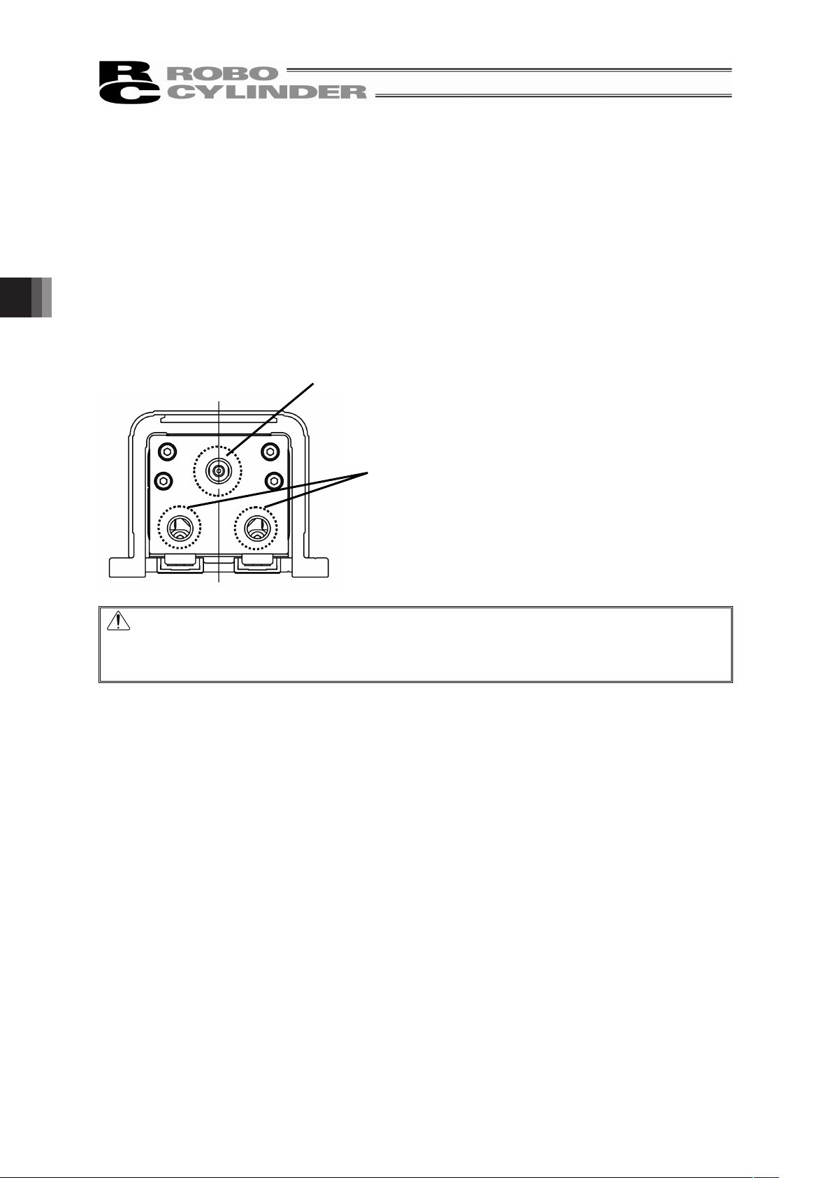
Detach the seals and ball screw guide by following the procedures described below so you can see the
guiding area to visually inspect the condition inside. In the inspection, it should be checked if dust is
involved inside and the condition of the lubricant.
Even if the grease looks brown, it will be fine as long as the sliding area seems wet and shiny.
If the grease is mixed with dust and dirty or has no shiny appearance, or if the grease has lost its
efficacy due to prolonged use, clean the applicable area and then replenish the grease.
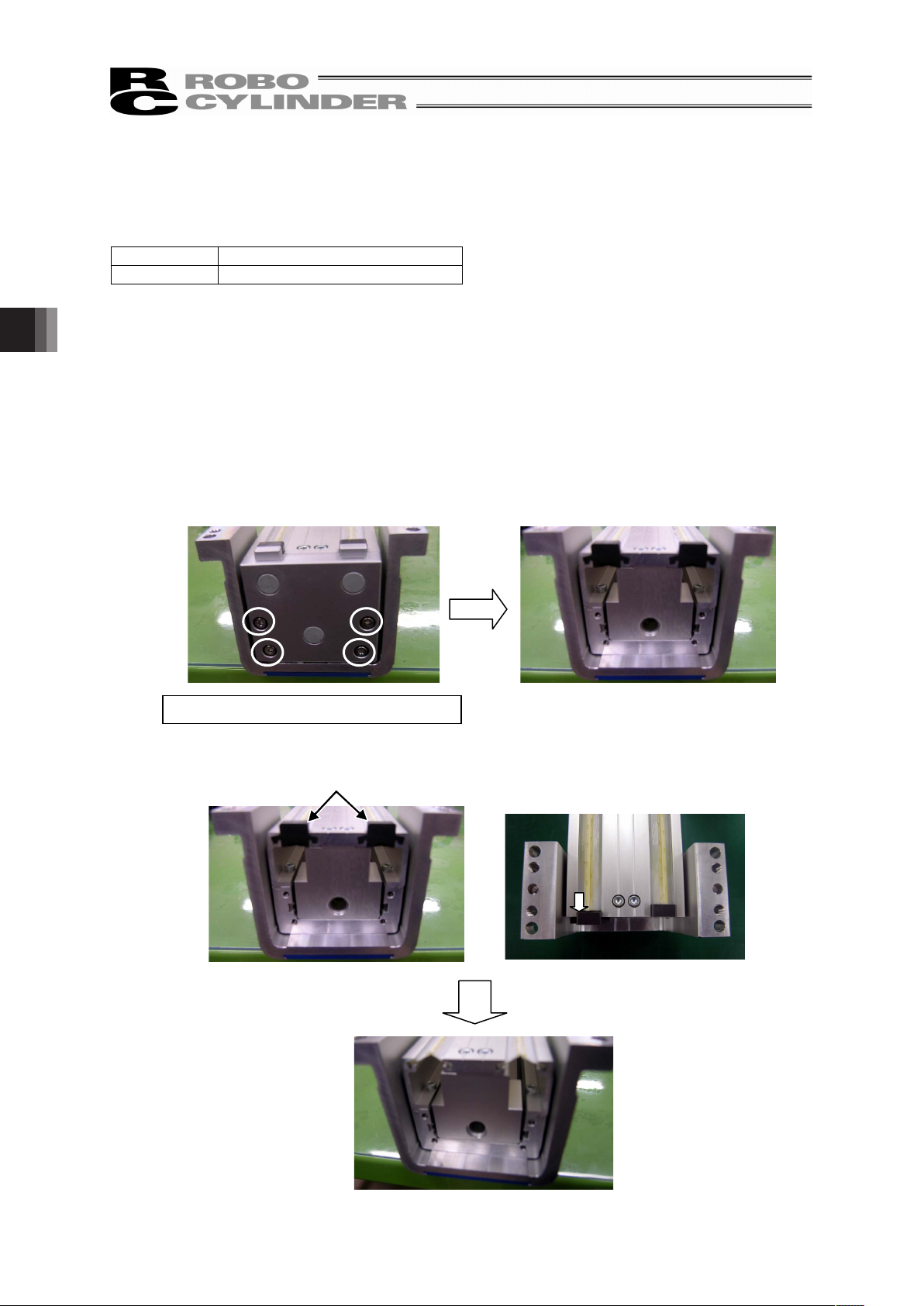
Described below is how to check inside.
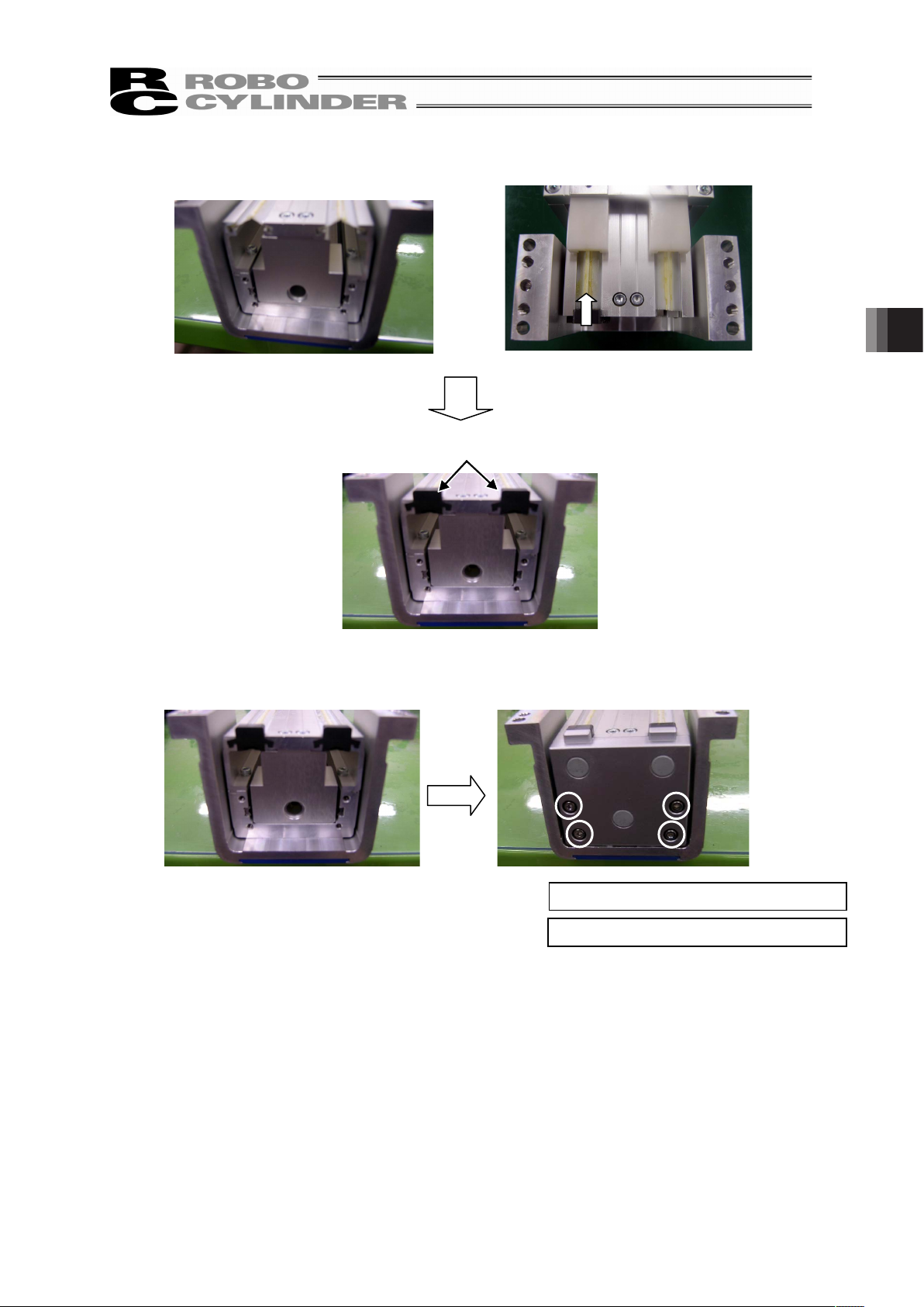
[Procedures to Detach Seals and Ball Screw Guide]
1) Loosen the four hex socket head cap screws holding the cover on the side opposite to the motor
(at the circled places) with a hex wrench to detach the cover.
2) Slide the terminal caps to remove them.
Tool to use: Hex wrench 2.5mm-sized
Edge Cap
Page 49
43
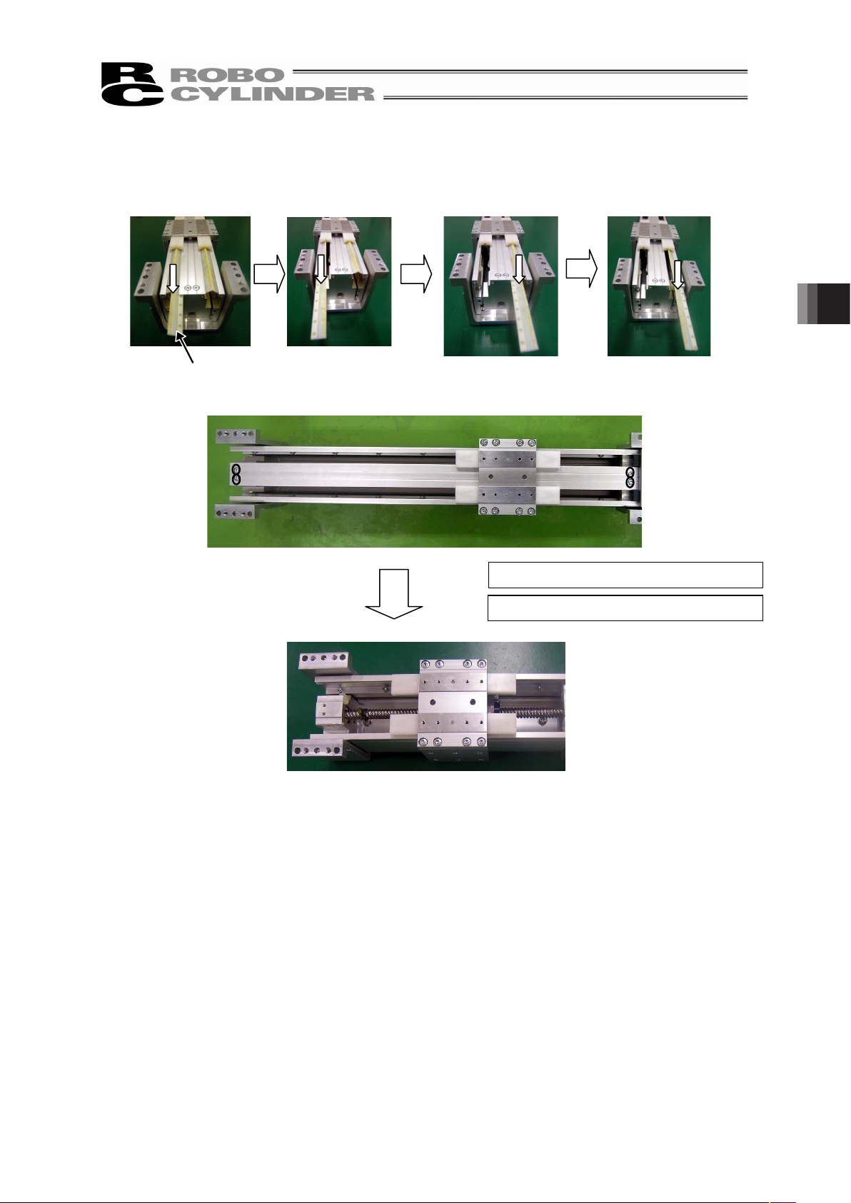
3) Pull out the four seals.
Next, loosen the four hex socket head cap screws holding the ball screw cover (at the circled
places) with a hex wrench to detach the cover.
Seal
Tightening Torque : 88.7N•cm
Tool to use: Hex wrench 2.5mm-sized
4. Maintenance Inspection
Page 50
4. Maintenance Inspection
44
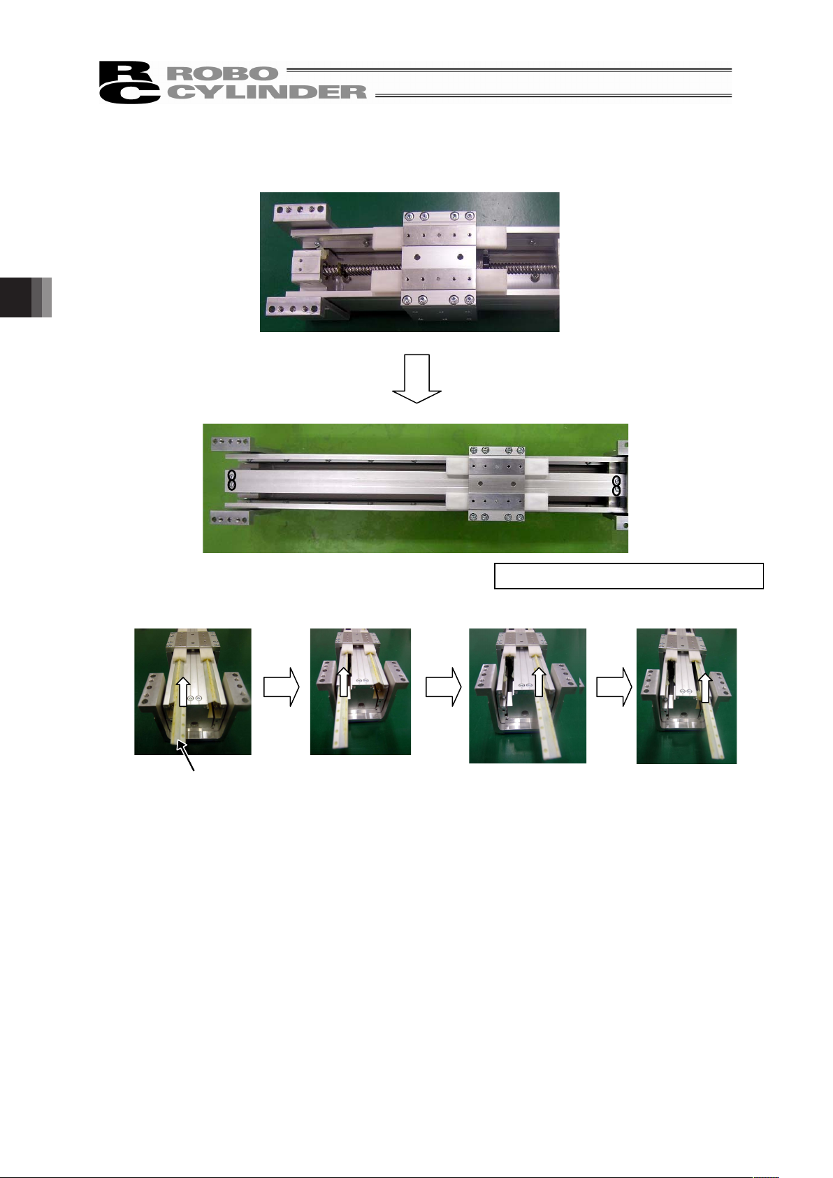
[Procedures to Detach Seals and Ball Screw Guide]
1) Tighten the four hex socket head cap screws to hold the ball screw cover (at the circled places)
with a hex wrench to attach the cover. Next, slide in the four seals to mount them.
Seal
Tool to use: Hex wrench 2.5mm-sized
Page 51
45
2) Slide in the terminal caps to attach them.
3) Tighten the four hex socket head cap screws to hold the cover on the side opposite to the motor
(at the circled places) with a hex wrench to attach the cover.
Edge Cap
Tightening Torque : 88.7N•cm
Tool to use: Hex wrench 2.5mm-sized
4. Maintenance Inspection
Page 52

4. Maintenance Inspection
46
4.5 Internal Cleanup
• When cleaning, wipe with a soft cloth to remove dust and dirt.
• Do not blow compressed air so dust would not get in from gaps.
• Do not use oil type solvent, neutral detergent or alcohol.
䎃
䎃
䎃
Page 53

47
4.6 Grease Supply
4.6.1 Applied Grease
[1] Standard type
The following grease is applied when the product is shipped out.
Idemitsu Kosan Co., Ltd. Daphne Eponex Grease No.2
Apart from above, there are equivalent sorts of grease sold in the market. For details contact a grease
supplier, provide the grease name shown above and ask them to select an equivalent.
Listed below are some equivalents for an example.
Showa Shell Sekiyu K. K. Alvania Grease No.2
Mobil Oil Mobilux 2
Warning: Do not attempt to apply fluorine grease. When mixed with lithium grease, not only
decrease the grease characteristics, but also may damage the actuator.
[2] Food grade grease type
The following grease is applied when the product is shipped out.
Taiyo Petroleum Gas Co., Ltd. Medallion FM Grease No.1
4. Maintenance Inspection
Page 54
4. Maintenance Inspection
48
4.6.2 How to Apply Grease
Grease supply is to be conducted at the grease supply holes on the front cover.
1. “Ball screw/guide supply hole” and “seal supply holes” are covered up with grommets.
Remove the grommets at three points.
2. Move the slider until it stops on the side opposite of the motor.
3. Insert a grease gun to the ball screw/guide supply hole and supply grease to the grease nipple
seen in the hole.
By supplying grease to the grease nipple, grease can be supplied to both the ball screw and
guide.
4. Insert a grease gun at the seal supply holes and apply grease to the seal on the actuator
openings.
5. Move the slider back and forth several times by hand.
6. Attach the grommet.
䎃
Caution: In case the grease got into your eye, immediately go see the doctor to get appropriate
care.
After finishing the grease supply work, wash your hands carefully with water and soap
to rinse the grease off.
Ball Screw/Guide Supply Hole (I8)
Seal Supply Holes (I8)
Page 55
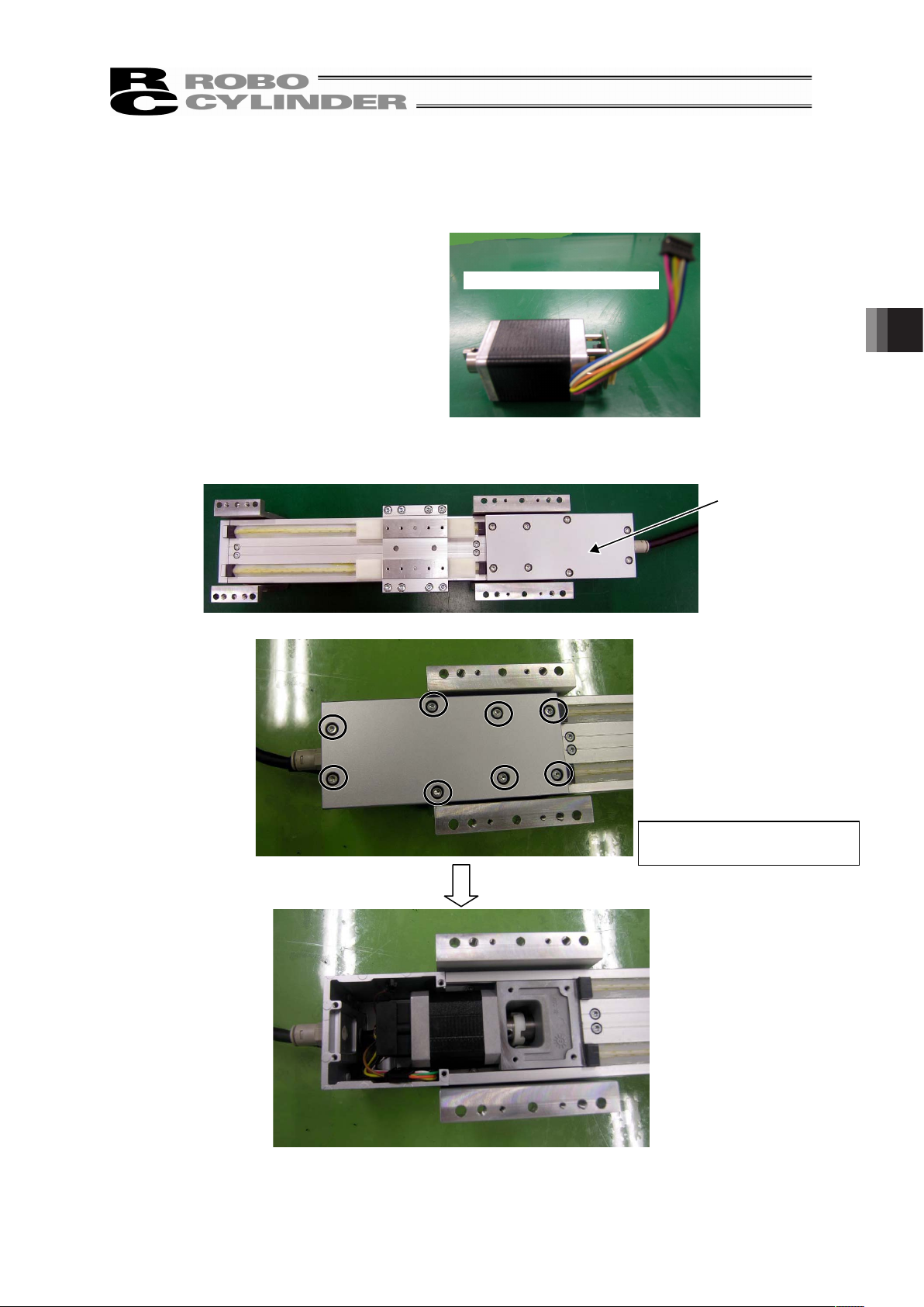
49
4.7 Motor Replacement Process
4.7.1 SA5C, SA6C
[Items Required for Replacement Work]
• Motor Unit for Replacement
• Hex Wrench
2mm, 2.5mm and 3mm-sized
[Step]
1) Loosen the eight hex socket head cap screws holding the bottom cover on the bottom of the
actuator (at the circled places) with a hex wrench to detach the cover.
Motor Unit for Replacement
Bottom Cover
Tool to use:
Hex wrench 2.5mm-sized
4. Maintenance Inspection
Page 56
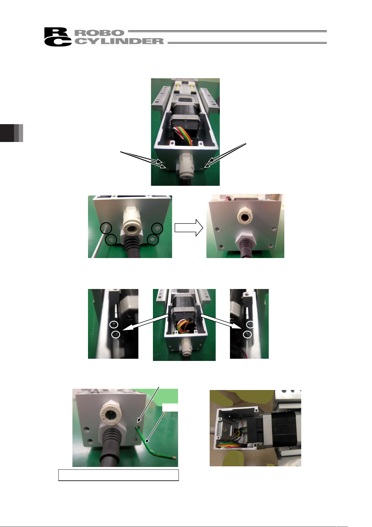
4. Maintenance Inspection
50
2) By using a tool with a long and slim shape such as a hex wrench, push in the four grommets (at the
circled places) on the back side to detach them.
3) Insert a hex wrench to the holes the grommets were taken out to detach the four hex socket head
cap screws holding the motor cover (at the circled places) with it.
Grommet
Grommet
Hole that the grommet
was taken out of
Hex Wrench
Tool to use: Hex wrench 2mm-sized
Page 57
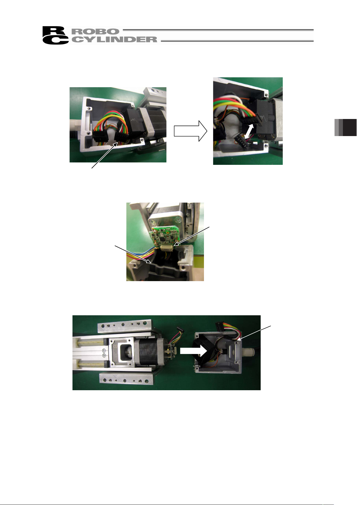
51
4) Unplug the motor cable connector.
5) Detach the protection cover for the encoder and unplug the encoder connector.
6) Detach the motor cover.
Motor Cable Connector
Encoder Protection
Cover
Encoder Connector
Motor Cover
4. Maintenance Inspection
Page 58

4. Maintenance Inspection
52
7) For SA5C and SA6C, the motor unit is held with screws from the direction shown with arrows.
Remove the ball screw cover and the seal, loosen the screws and then detach the motor unit.
Loosen the four hex socket head cap screws holding the cover on the side opposite to the motor (at
the circled places) with a hex wrench to detach the cover.
8) Slide the terminal caps to remove them.
Seal
Ball Screw Cove
r
Seal
T
ool to use: Hex wrench 2.5mm-sized
Edge Cap
Page 59

53
9) Pull out the four seals.
Next, loosen the four hex socket head cap screws holding the ball screw cover (at the circled
places) with a hex wrench to detach the cover.
Seal
Tool to use: Hex wrench 2.5mm-sized
Ball Screw Cover
Seal
4. Maintenance Inspection
Page 60

4. Maintenance Inspection
54
10) Detach the two screws holding the ball screw cover bracket (at the circled places) with a hex
wrench.
11) Remove the two screws (for SA5C) and four screws (for SA6C) holding the motor (at the circled
places) with a hex wrench and detach the motor.
12) Rotate the coupling on the replacement motor unit to adjust the position of the protrusion on it so it
fits to the recessed slit.
Ball Screw
Cover Bracket
Tool to use: Hex wrench 2.5mm-sized (SA5C)
3.0mm-sized
(SA6C)
Tool to use : Hex wrench 2.5mm-sized
Recessed
slit
Coupling protrusion
on replacement
motor unit
Page 61

55
13) Tighten the two screws (for SA5C) and four screws (for SA6C) to hold the motor (at the circled
places) with a hex wrench to attach the motor.
14) Tighten the two screws to hold the ball screw cover bracket (at the circled places) with a hex
wrench to attach the ball screw cover bracket.
Motor
Tightening Torque : 88.7N•cm
Tool to use: Hex wrench 2.5mm-sized
Ball Screw Cover
Bracket
Tool to use: Hex wrench 2.5mm-sized (SA5C)
3.0mm-sized
(
SA6C
)
Tightening Torque : 88.7N•cm (SA5C)
207N•cm
(
SA6C
)
4. Maintenance Inspection
Page 62

4. Maintenance Inspection
56
15) Tighten the four hex socket head cap screws to hold the ball screw cover (at the circled places) with
a hex wrench to attach the cover. Next, slide in the four seals to mount them.
Ball Screw Cover
Seal
Tightening Torque : 88.7N•cm Tool to use: Hex wrench 2.5mm-sized
Seal
Page 63

57
16) Slide in the terminal caps to attach them.
17) Tighten the four hex socket head cap screws to hold the cover on the side opposite to the motor (at
the circled places) with a hex wrench to attach the cover.
Edge Cap
Tightening Torque : 88.7N•cm
Tool to use: Hex wrench 2.5mm-sized
4. Maintenance Inspection
Page 64

4. Maintenance Inspection
58
18) Attach the motor cover and plug in the encoder connector.
Encoder Protection
Cover
Encoder Connector
Motor Cover
Page 65

59
19) Put the encoder protection cover on the encoder.
20) Plug in the motor cable connector.
Encoder Protection Cover
Motor Cable Connector
4. Maintenance Inspection
Page 66
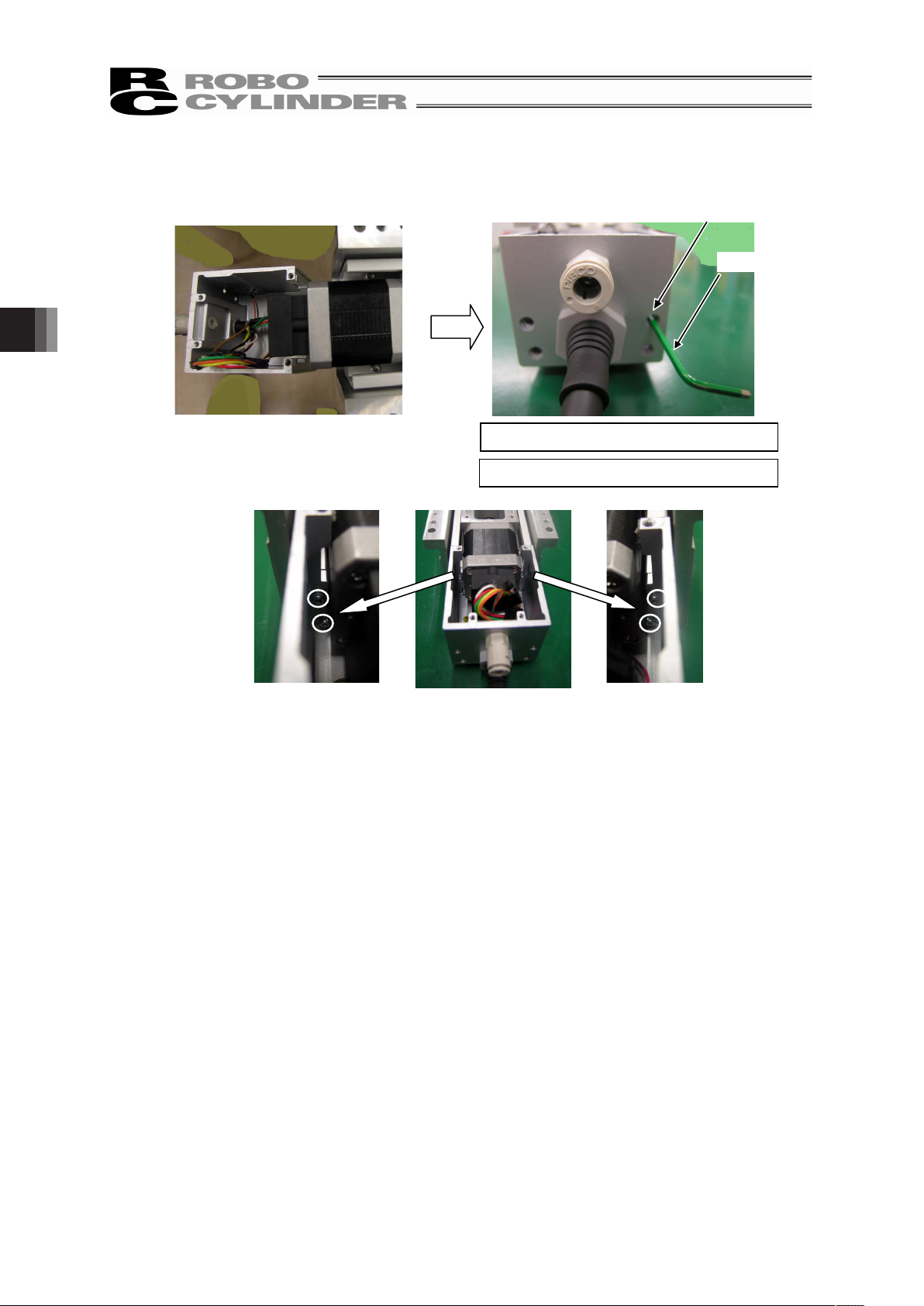
4. Maintenance Inspection
60
21) Insert a hex wrench to the holes the grommets were taken out of to tighten the four hex socket head
cap screws to hold the motor cover (at the circled places) with it.
Hole that the grommet
was taken out of
Hex Wrench
Tightening Torque : 49.8N•cm
Tool to use: Hex wrench 2mm-sized
Page 67
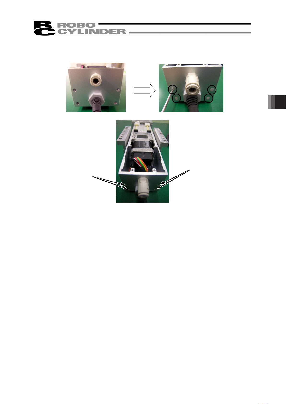
61
22) By using a tool with a long and slim shape such as a hex wrench, push in the four grommets (at the
circled places) on the back.
Grommet
Grommet
4. Maintenance Inspection
Page 68
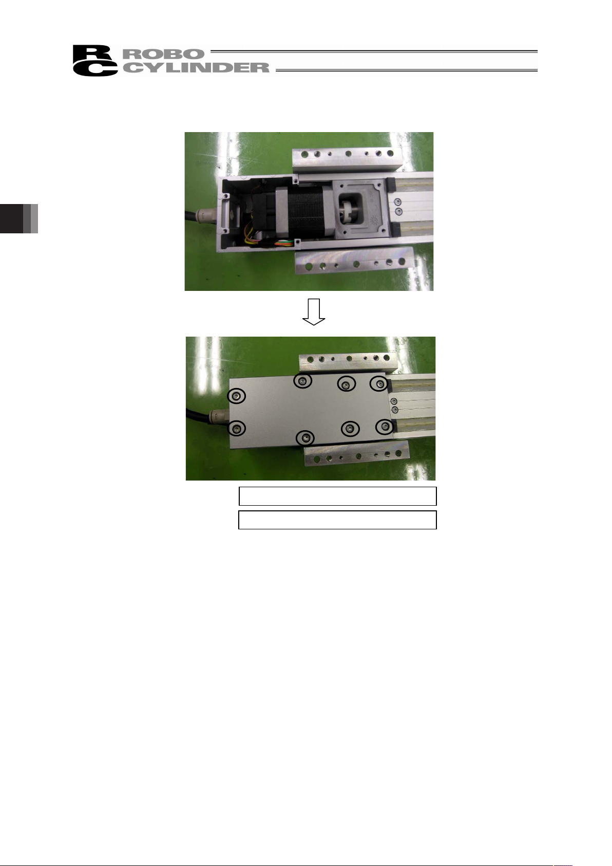
4. Maintenance Inspection
62
23) Attach the bottom cover at the bottom of the actuator and tighten the eight hex socket head cap
screws (at circled places) with a hex wrench to affix the cover.
Tightening Torque : 88.7N•cm
Tool to use: Hex wrench 2.5mm-sized
Page 69
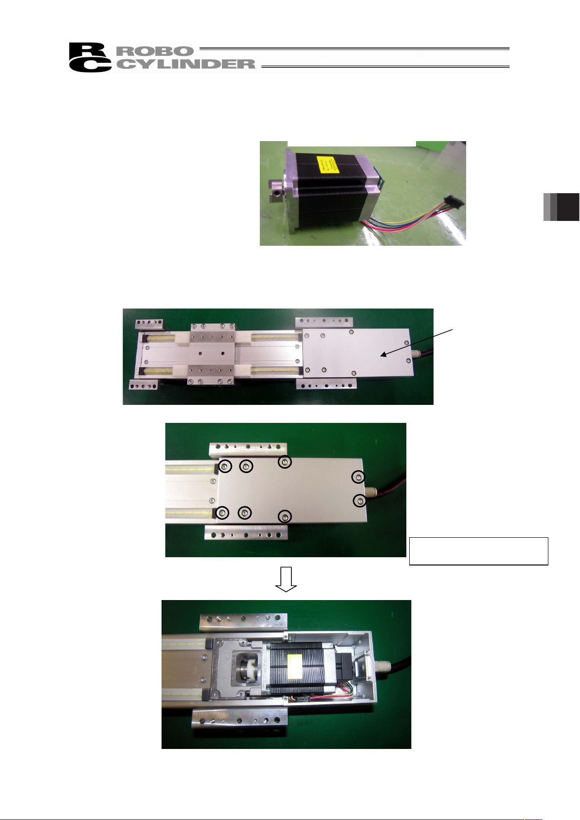
63
4.7.2 SA7C
[Items Required for Replacement Work]
• Motor Unit for Replacement
• Hex Wrench
2mm, 2.5mm and 3mm-sized
[Step]
1) Loosen the eight hex socket head cap screws holding the bottom cover on the bottom of the
actuator (at the circled places) with a hex wrench to detach the cover.
Motor Unit for Replacement
Bottom Cover
Tool to use:
Hex wrench 2.5mm-sized
4. Maintenance Inspection
Page 70
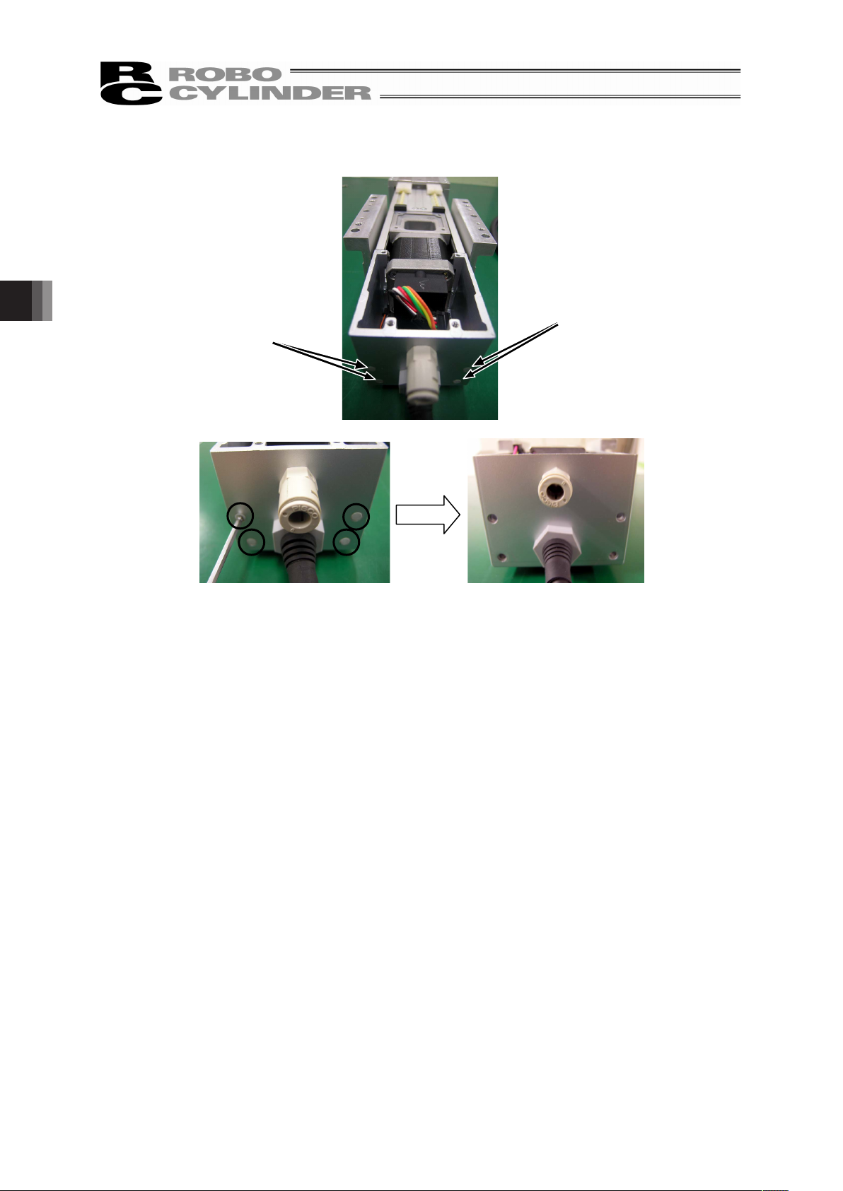
4. Maintenance Inspection
64
2) By using a tool with a long and slim shape such as a hex wrench, push in the four grommets (at the
circled places) on the back side to detach them.
Grommet
Grommet
Page 71
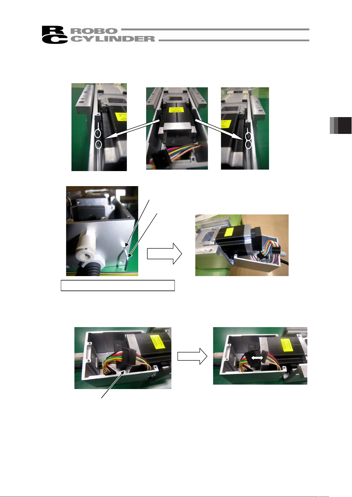
65
3) Insert a hex wrench to the holes the grommets were taken out of to detach the four hex socket head
cap screws holding the motor cover (at the circled places) with it.
4) Unplug the motor cable connector.
Hole that the grommet
was taken out of
Hex Wrench
Tool to use: Hex wrench 2mm-sized
Motor Cable Connector
4. Maintenance Inspection
Page 72
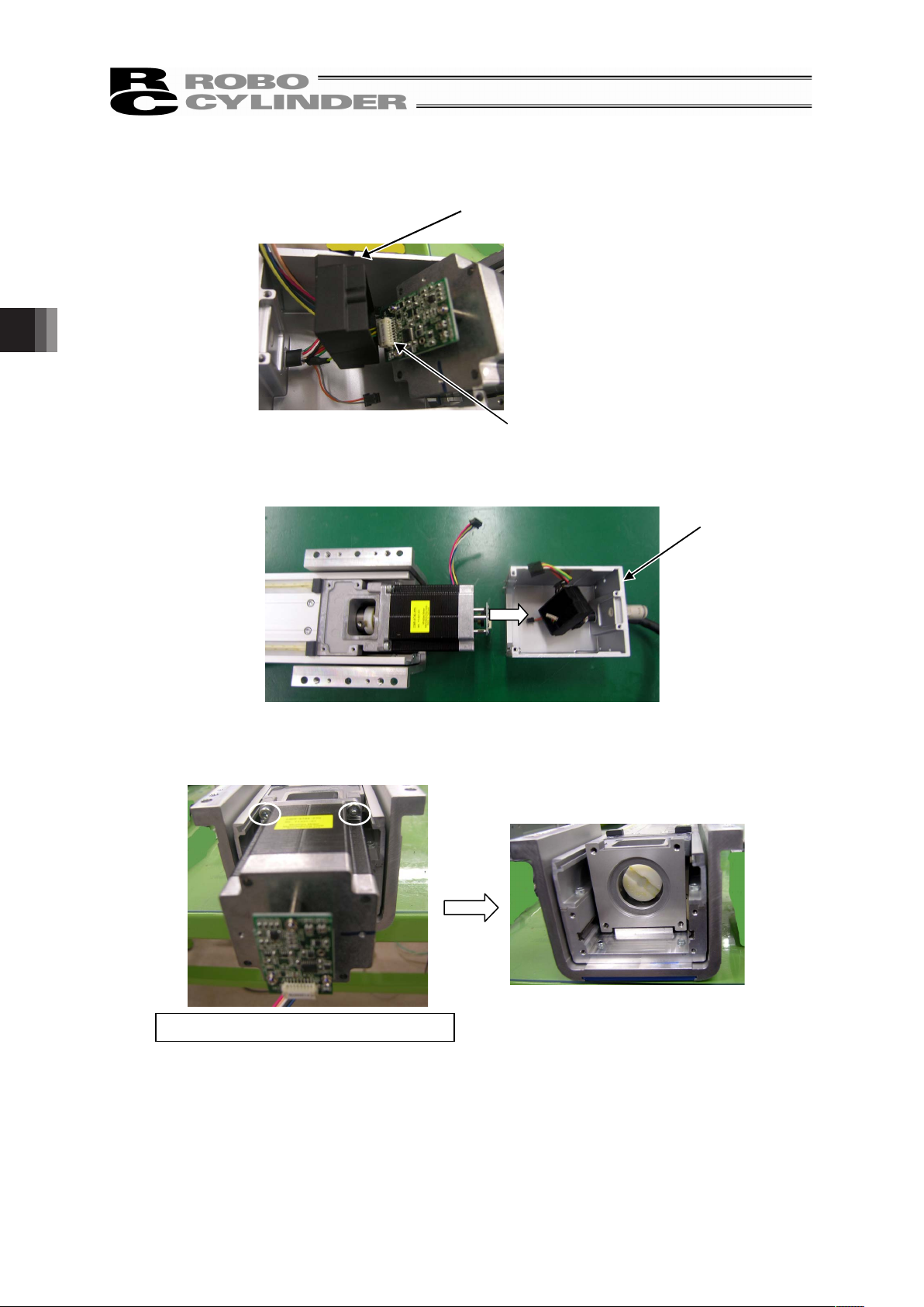
4. Maintenance Inspection
66
5) Detach the protection cover for the encoder and unplug the encoder connector.
6) Detach the motor cover.
7) Remove the four screws holding the motor (at circled places) with a hex wrench to detach the
motor.
Encoder Protection
Cover
Encoder Connector
Motor Cover
Tool to use: Hex wrench 3mm-sized
Page 73
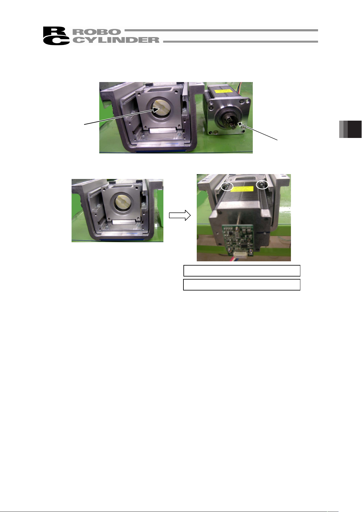
67
8) Rotate the coupling on the replacement motor unit to adjust the position of the protrusion on it so it
fits to the recessed slit.
9) Attach the motor and tighten the four screws to hold the motor (at circled places) with a hex wrench.
Recessed
slit
Coupling protrusion
on replacement
motor unit
Tightening Torque : 207N•cm
Tool to use: Hex wrench 3mm-sized
4. Maintenance Inspection
Page 74

4. Maintenance Inspection
68
10) Attach the motor cover and plug in the encoder connector.
11) Plug in the motor cable connector.
Encoder Protection Cover
Encoder Connector
Motor Cover
Motor Cable Connector
Page 75

69
12) Insert a hex wrench to the holes the grommets were taken out of to tighten the four hex socket head
cap screws to hold the motor cover (at the circled places) with it.
Hole that the
grommet was taken
out of
Hex Wrench
Tightening Torque : 49.8N•cm
Tool to use: Hex wrench 2mm-sized
4. Maintenance Inspection
Page 76

4. Maintenance Inspection
70
13) By using a tool with a long and slim shape such as a hex wrench, push in the four grommets (at the
circled places) on the back.
Grommet
Grommet
Page 77

71
14) Attach the bottom cover at the bottom of the actuator and tighten the eight hex socket head cap
screws (at circled places) with a hex wrench to affix the cover.
Tightening Torque : 88.7N•cm
Tool to use: Hex wrench 2.5mm-sized
4. Maintenance Inspection
Page 78

4. Maintenance Inspection
72
4.8 Seal (opening) Replacement Process
[Items Required for Replacement Work]
• Seal
• Hex Wrench
2.5mm-sized
[Step]
1) Loosen the four hex socket head cap screws holding the cover on the side opposite to the motor (at
the circled places) with a hex wrench to detach the cover.
2) Slide the terminal caps to remove them.
Seal
Tool to use: Hex wrench 2.5mm-sized
Edge Cap
Page 79

73
3) Pull the seals to take them out.
Seal
4. Maintenance Inspection
Page 80

4. Maintenance Inspection
74
4) Insert the seals for replacement to attach them.
5) Slide in the terminal caps to attach them.
Seal
Edge Cap
Page 81
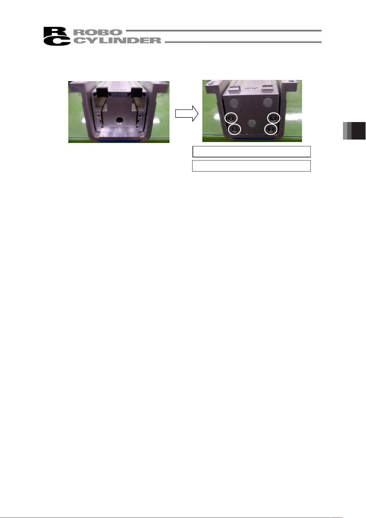
75
6) Tighten the four hex socket head cap screws to hold the cover on the side opposite to the motor (at
the circled places) with a hex wrench to attach the cover.
Tightening Torque : 88.7N•cm
Tool to use: Hex wrench 2.5mm-sized
4. Maintenance Inspection
Page 82

5. External Dimensions
76
5. External Dimensions
[SA5 Standard Type]
5
(Secure at least 100)
5
STROKE10 50 29 9045
A 61
L
25
7.5357.5
22.5
(From unit attachment surface)
25
(Reamed Hole Pitch ±0.02)
4-M4, depth 6
(Same on the Opposite Side)
2-φ4H7, depth 4
(Same on the Opposite Side)
Home ME
ME SE
55
25
7.5357.5 303022.5
55
55
2-M3, depth 3
4-M3, depth 7
35
(Reamed Hole Pitch ±0.02)
70
2-φ4H7, depth 4
4-M4, depth 7
25
51020105
30
(Reamed Hole Pitch ±0.02)
45
20
10
50
70
B
C
D
22.5
2012.5
355
75
75
(Reamed Hole Pitch ±0.02)
5
2-φ3H7, depth 5
8-M3, depth 6
2-φ4.1, depth 4
8-M4 through
8-φ4.5 hole
2-φ4H7, depth 4
(17)
Cable exit direction: Left
85
7.5
Main Unit Height: 63.5
Slider Height: 65
Bracket Width: 67
Slider Width: 70
Motor Area
Height: 56
Air Inlet
φ6 for Air Purge
Cable exit
direction: Left
Cable exit
direction: Right
STROKE L A B C D
Weight [kg]
100 385 324 256.5 221.5 204
2.8
150 435 374 306.5 271.5 254
2.9
200 485 424 356.5 321.5 304
3.1
250 535 474 406.5 371.5 354
3.2
300 585 524 456.5 421.5 404
3.4
350 635 574 506.5 471.5 454
3.5
400 685 624 556.5 521.5 504
3.7
450 735 674 606.5 571.5 554
3.8
500 785 724 656.5 621.5 604
4.0
Page 83

77
[SA5 Wall-hang Type]
5 5
STROKE10
45B22.5
5
85
2-φ5H7, depth 5
(from the other side)
2-φ5.1, depth 5
(from the other side)
29 905045
A 61
L
8-φ5.5 hole
8-M5 through
3030
20
10
50
70
25
7.5357.5
42.5
C2012.5
355 D
16
16
5
2-M3, depth 6
2-M3, depth 6
4-M4, depth 6
(Same on the Opposite Side)
2-φ4H7, depth 4
(Same on the Opposite Side)
Home
MEME SE
55
3030
12
25
7.5357.5
21.5
470
7.5 30
12
2-M3, depth 64-M4, depth 6
2-φ4H7, depth 4
2-M3, depth 6
(17)
25
51020105
24
8-M3, depth 6
2-φ3H7, depth 5
6
10
39
66.5
74
21.5
Slider Height: 63.5
10
95
Unit Attachment Surface
Wall Hanging on Left Side
35
(Reamed Hole Pitch ±0.02)
(Secure at least 100)
Cable exit
direction: Left
Cable exit
direction: Right
Air Inlet
φ6 for Air Purge
Wall Hanging on Right Side
85
(Reamed Hole Pitch ±0.02)
30
(Reamed Hole Pitch ±0.02)
Cable exit
direction: Left
25
(Reamed Hole Pitch ±0.02)
30
7.5
7.5
9
7.5
STROKE L A B C D
Weight [kg]
100 385 324 256.5 221.5 204
2.8
150 435 374 306.5 271.5 254
2.9
200 485 424 356.5 321.5 304
3.1
250 535 474 406.5 371.5 354
3.2
300 585 524 456.5 421.5 404
3.4
350 635 574 506.5 471.5 454
3.5
400 685 624 556.5 521.5 504
3.7
450 735 674 606.5 571.5 554
3.8
500 785 724 656.5 621.5 604
4.0
5. External Dimensions
Page 84

5. External Dimensions
78
[SA5 Ceiling Type]
5 5
STROKE10 50 29 9045
A 61
L
25
7.5357.5
19
4-M4, depth 6
(Same on the Opposite Side)
2-φ4H7, depth 4
(Same on the Opposite Side)
Home MEME SE
55
25
7.5357.5
70
45
20
10
50
70
B
C
D355
2012.5
22.5
85
5
4-M4, depth 6
2-φ4H7, depth 4
2-φ5H7, depth 5
8-φ5.5 hole
8-M5 through
2-φ5.1, depth 5
25
51020105
16
3030
16
7.5 30
8-M3, depth 6
2-φ3H7, depth 5
2-M3,
depth 6
(17)
2-M3, depth 6
6
Slider Height: 65
95
Slider Width: 70
Unit Attachment Surface
35
(Reamed Hole Pitch ±0.02)
85
(Reamed Hole Pitch ±0.02)
Cable exit
direction: Left
Cable exit
direction: Right
Air Inlet
φ6 for Air Purge
Cable exit direction: Left
25
(Reamed Hole Pitch ±0.02)
30
(Reamed Hole Pitch ±0.02)
(Secure at least 100)
64
63.5
1.5
36
35
36
STROKE L A B C D
Weight [kg]
100 385 324 256.5 221.5 204
2.8
150 435 374 306.5 271.5 254
2.9
200 485 424 356.5 321.5 304
3.1
250 535 474 406.5 371.5 354
3.2
300 585 524 456.5 421.5 404
3.4
350 635 574 506.5 471.5 454
3.5
400 685 624 556.5 521.5 504
3.7
450 735 674 606.5 571.5 554
3.8
500 785 724 656.5 621.5 604
4.0
Page 85

79
[SA6 Standard Type]
5 5
10 STROKE45 60 29 90
A 61
L
30
7.5457.5
2-φ5H7, depth 5
(Same on the Opposite Side)
4-M5, depth 7.5
(Same on the Opposite Side)
Home MEME SE
3030
30
7.5457.5
80
55
22.5
55
2-M3, depth 4
2-φ5H7, depth 5
4-M5, depth 8
4-M3, depth 8
62
30
5
12.5
25
12.5
5
B 45
50
70 10
20C
D35
20
22.5
5
12.5
5
8-M5 through
2-φ5H7, depth 5
2-φ3H7, depth 5
8-M3, depth 6
2-φ5.1, depth 5
(17)
85
Cable exit direction: Left
95
9.5
Main Unit Height: 73.5
Slider Height: 75
Bracket Width: 77
Slider Width: 80
45
(Reamed Hole Pitch ±0.02)
30
(Reamed Hole Pitch ±0.02)
37
(Reamed Hole Pitch ±0.02)
85
(Reamed Hole Pitch ±0.02)
25
(From unit attachment surface)
8-φ5.5 hole
Air Inlet
φ6 for Air Purge
Cable exit
direction: Left
Cable exit
direction: Right
Motor Area
Height: 65
(Secure at least 100)
STROKE L A B C D
Weight [kg]
100 395 334 266.5 231.5 214
3.8
150 445 384 316.5 281.5 264
4.1
200 495 434 366.5 331.5 314
4.3
250 545 484 416.5 381.5 364
4.5
300 595 534 466.5 431.5 414
4.7
350 645 584 516.5 481.5 464
4.9
400 695 634 566.5 531.5 514
5.1
450 745 684 616.5 581.5 564
5.3
500 795 734 666.5 631.5 614
5.5
550 845 784 716.5 681.5 664
5.8
600 895 834 766.5 731.5 714
6.0
5. External Dimensions
Page 86
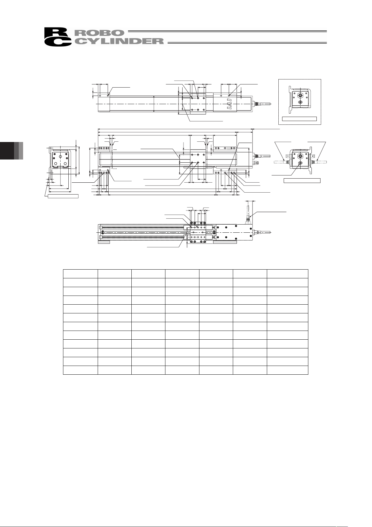
5. External Dimensions
80
[SA6 Wall-hang Type]
5
STROKE
5
10
95
60 29 90
A
45
61
L
30
45 7.57.5
30 30
45
20
1070
50
16
5
B
C
D
20
355
12.5
22.5
7.5 30
16
44.5
2-M3, depth 6
2-M3, depth 6
4-M5, depth 8
(Same on the Opposite Side)
2-φ5H7, depth 5
(Same on the Opposite Side)
2-φ5.1, depth 5
(from the other side)
2-φ5H7, depth 5
(from the other side)
5
Home MEME SE
3030
12
30
7.5457.5
3.5
21
80
7.5 30
12
2-M3, depth 6
2-M3, depth 6
62
4-M5, depth 8
2-φ5H7, depth 5
30
5
12.5
25
12.5
5
25
(17)
2-φ3H7, depth 5
8-M3, depth 6
Cable exit direction: Left
11
43.5
6
Main Unit: 74.5
Slider: 83.5
21
Slider Height: 73.5
10.5
105
Unit Attachment Surface
8-φ5.5 hole
8-M5 through
95
(Reamed Hole Pitch ±0.02)
45
(Reamed Hole Pitch ±0.02)
30
(Reamed Hole Pitch ±0.02)
37
(Reamed Hole Pitch ±0.02)
Wall Hanging on Right Side
Cable exit
direction: Left
Cable exit
direction: Right
Air Inlet
φ6 for Air Purge
(Secure at least 100)
Wall Hanging on Left Side
8.5
10
8.5
STROKE L A B C D
Weight [kg]
100 395 334 266.5 231.5 214
3.8
150 445 384 316.5 281.5 264
4.1
200 495 434 366.5 331.5 314
4.3
250 545 484 416.5 381.5 364
4.5
300 595 534 466.5 431.5 414
4.7
350 645 584 516.5 481.5 464
4.9
400 695 634 566.5 531.5 514
5.1
450 745 684 616.5 581.5 564
5.3
500 795 734 666.5 631.5 614
5.5
550 845 784 716.5 681.5 664
5.8
600 895 834 766.5 731.5 714
6.0
Page 87
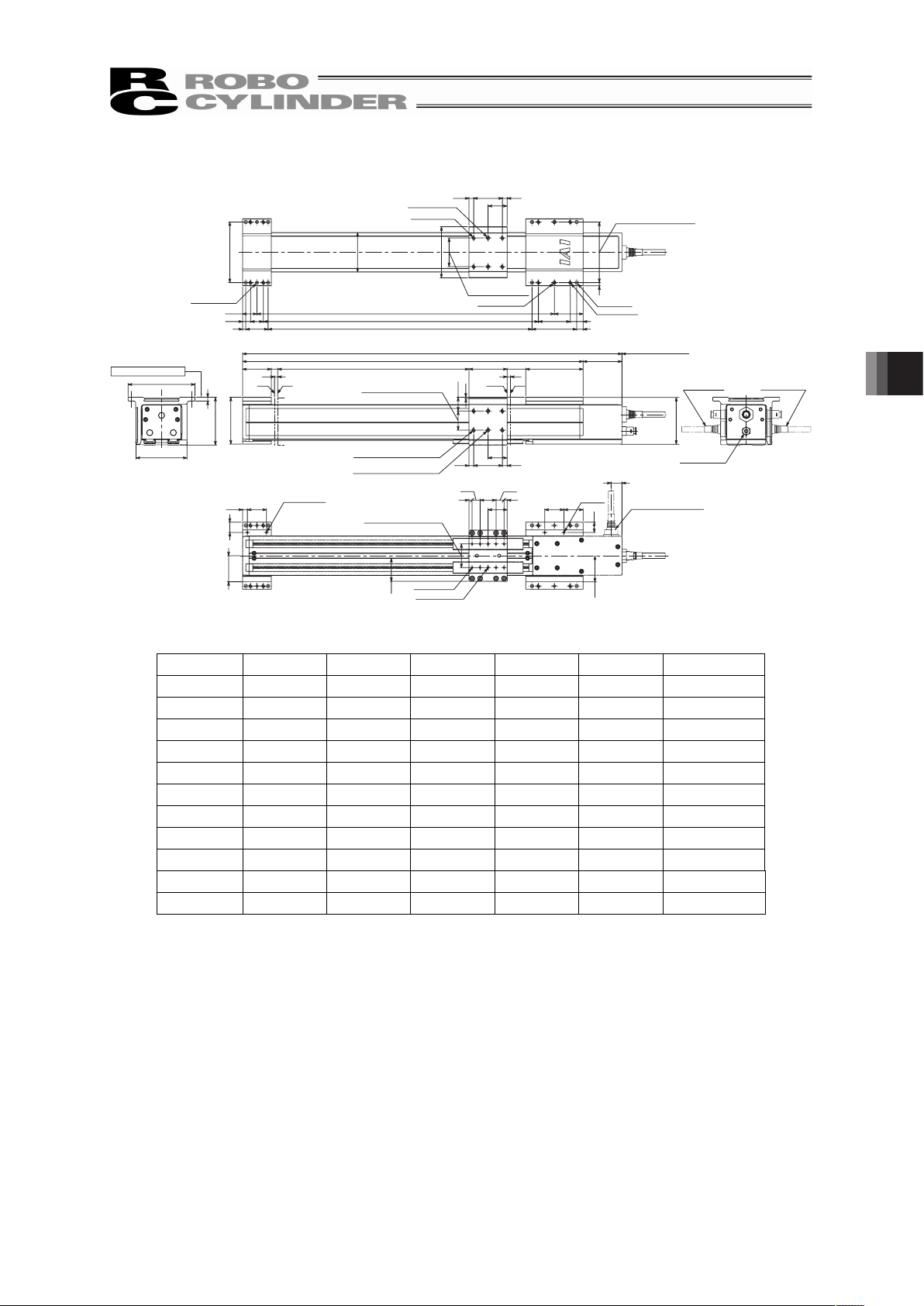
81
[SA6 Ceiling Type]
5 5
STROKE10 60 29 90
61A
45
L
30
7.5457.5
21.5
4-M5, depth 8
(Same on the Opposite Side)
2-φ5H7, depth 5
(Same on the Opposite Side)
Home MEME SE
62
30
7.5457.5
80
5
45
2050
1070
B
C
D
2012.5
355
22.5
4-M5, depth 8
2-φ5H7, depth 5
2-φ5H7, depth 5
2-φ5.1, depth 5
95
16
303030
5
12.5
25
12.5
5
16
7.5 30
2-M3, depth 6
8-M3, depth 6
2-φ3H7, depth 5
2-M3,
depth 6
(17)
105
6
Slider Height: 75
Slider Width: 80
Unit Attachment Surface
30
(Reamed Hole Pitch ±0.02)
37
(Reamed Hole Pitch ±0.02)
45
(Reamed Hole Pitch ±0.02)
95
(Reamed Hole Pitch ±0.02)
8-φ5.5 hole
8-M5 through
(Secure at least 100)
Cable exit
direction: Left
Cable exit
direction: Right
Air Inlet
φ6 for Air Purge
Cable exit direction: Left
73.5
73.5
40
1.5
40.5
40.5
STROKE L A B C D
Weight [kg]
100 395 334 266.5 231.5 214
3.8
150 445 384 316.5 281.5 264
4.1
200 495 434 366.5 331.5 314
4.3
250 545 484 416.5 381.5 364
4.5
300 595 534 466.5 431.5 414
4.7
350 645 584 516.5 481.5 464
4.9
400 695 634 566.5 531.5 514
5.1
450 745 684 616.5 581.5 564
5.3
500 795 734 666.5 631.5 614
5.5
550 845 784 716.5 681.5 664
5.8
600 895 834 766.5 731.5 714
6.0
5. External Dimensions
Page 88
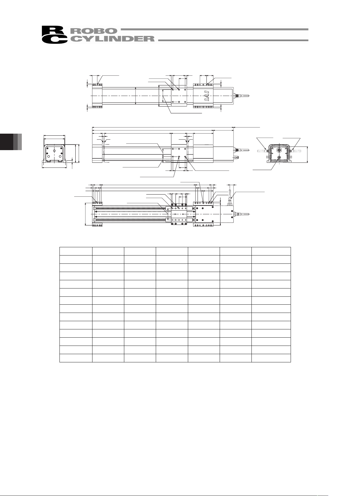
5. External Dimensions
82
[SA7 Standard Type]
STROKE10
55
70 29 90
91
45
L
27
(From unit attachment surface)
7.5557.5
35
2-φ5H7, depth 5
(Same on the Opposite Side)
A
4-M5, depth 7.5
(Same on the Opposite Side)
Home
ME
ME SE
35
7.555
2-φ5H7, depth 5
7.5
95
3030
4-M5, depth 8
4-M3, depth 8
22.5 2-M3, depth 4
5 5
55
77
5
45
10
2050
70
5153015
35
20
35
5
B
C
D5
12.5
2-φ5.1, depth 5
100
8-M3, depth 6
2-φ3H7, depth 5
2-φ5H7, depth 5
(17)
22.5
110
Slider Width: 95
Bracket Width: 92
9.5
Slider Height: 82
Main Unit Height: 80.5
35
(Reamed Hole Pitch ±0.02)
55
(Reamed Hole Pitch ±0.02)
100
(Reamed Hole Pitch ±0.02)
52
(Reamed Hole Pitch ±0.02)
8-M5 through
8-φ5.5 hole
Cable exit direction: Left
Motor Area
Height: 72
Air Inlet
φ6 for Air Purge
Cable exit
direction: Left
Cable exit
direction: Right
(Secure at least 100)
STROKE L A B C D
Weight [kg]
100 435 344 276.5 241.5 224
5.9
150 485 394 326.5 291.5 274
6.2
200 535 444 376.5 341.5 324
6.5
250 585 494 426.5 391.5 374
6.8
300 635 544 476.5 441.5 424
7.1
350 685 594 526.5 491.5 474
7.4
400 735 644 576.5 541.5 524
7.6
450 785 694 626.5 591.5 574
7.9
500 835 744 676.5 641.5 624
8.2
550 885 794 726.5 691.5 674
8.5
600 935 844 776.5 741.5 724
8.8
650 985 894 826.5 791.5 774
9.0
700 1035 944 876.5 841.5 824
9.3
Page 89
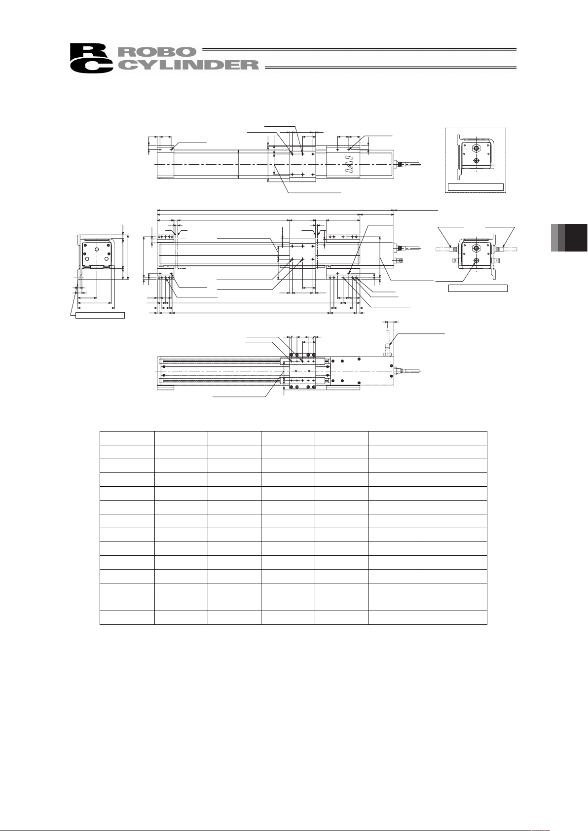
83
[SA7 Wall-hang Type]
STROKE
55
10
45B22.5
70
7.5557.5
35
2-φ5H7, depth 5
(Same on the Opposite Side)
29 90
A
45
L
91
54.5
4-M5, depth 8
(Same on the Opposite Side)
5
2050
70 10
C
D
20
35
12.5
5
3030
16
2-M3, depth 6
2-φ5H7, depth 5
(from the other side)
2-φ5.1, depth 5
(from the other side)
7.5 30
2-M3, depth 6
16
5 110
Home
ME
ME SE
35
7.5557.5
95 3.5
12
3030
23.5
2-M3, depth 6
2-M3, depth 6
12
7.5 30
4-M5, depth 8
2-φ5H7, depth 5
77
5153015355
8-M3, depth 6
2-φ3H7, depth 5
(17)
25
Slider: 80.5
29
120
11
Slider: 98.5
10.5
Main Unit: 89.5
6
51
Unit Attachment Surface
35
(Reamed Hole Pitch ±0.02)
55
(Reamed Hole Pitch ±0.02)
110
(Reamed Hole Pitch ±0.02)
52
(Reamed Hole Pitch ±0.02)
8-φ5.5 hole
8-M5 through
(Secure at least 100)
Cable exit
direction: Left
Cable exit
direction: Right
Air Inlet
φ6 for Air Purge
Wall Hanging on Right Side
Wall Hanging on Left Side
Cable exit direction: Left
8.5
10
8.5
STROKE L A B C D
Weight [kg]
100 435 344 276.5 241.5 224
5.9
150 485 394 326.5 291.5 274
6.2
200 535 444 376.5 341.5 324
6.5
250 585 494 426.5 391.5 374
6.8
300 635 544 476.5 441.5 424
7.1
350 685 594 526.5 491.5 474
7.4
400 735 644 576.5 541.5 524
7.6
450 785 694 626.5 591.5 574
7.9
500 835 744 676.5 641.5 624
8.2
550 885 794 726.5 691.5 674
8.5
600 935 844 776.5 741.5 724
8.8
650 985 894 826.5 791.5 774
9.0
700 1035 944 876.5 841.5 824
9.3
5. External Dimensions
Page 90

84
[SA7 Ceiling Type]
STROKE
55
10 70
7.5557.5
35
2-φ5H7, depth 5
(Same on the Opposite Side)
4-M5, depth 8
(Same on the Opposite Side)
45 29 90
A 91
L
21.5
Home
ME
ME SE
35
7.5557.5
95
10
45
20
70
50
4-M5, depth 8
2-φ5H7, depth 5
B
C
D
20
35
22.5
12.5
5
2-φ5H7, depth 5
2-φ5.1, depth 5
5
110
77
5153015355
(17)
3030
16
2-φ3H7, depth 5
8-M3, depth 6
7.5 30
16
2-M3, depth 6
2-M3, depth 6
Cable exit direction: Left
120
Slider Width: 95
Slider Height: 82
86
6
Unit Attachment Surface
35
(Reamed Hole Pitch ±0.02)
52
(Reamed Hole Pitch ±0.02)
55
(Reamed Hole Pitch ±0.02)
110
(Reamed Hole Pitch ±0.02)
(Secure at least 100)
8-φ5.5 hole
8-M5 through
Cable exit
direction: Left
Cable exit
direction: Right
Air Inlet
φ6 for Air Purge
48
47.5
48
86
1.5
80.5
STROKE L A B C D
Weight [kg]
100 435 344 276.5 241.5 224
5.9
150 485 394 326.5 291.5 274
6.2
200 535 444 376.5 341.5 324
6.5
250 585 494 426.5 391.5 374
6.8
300 635 544 476.5 441.5 424
7.1
350 685 594 526.5 491.5 474
7.4
400 735 644 576.5 541.5 524
7.6
450 785 694 626.5 591.5 574
7.9
500 835 744 676.5 641.5 624
8.2
550 885 794 726.5 691.5 674
8.5
600 935 844 776.5 741.5 724
8.8
650 985 894 826.5 791.5 774
9.0
700 1035 944 876.5 841.5 824
9.3
5. External Dimensions
Page 91

85
6. Product Life
The mechanical life of the actuator is represented by the guide that receives the moment load mostly.
One factor that affects the traveling life of an actuator is “Rated Load”.
There are two types of rated loads: “Static Rated Load” and “Dynamic Rated Load”.
• “Static Rated Load” : Load applied while the actuator is stopped, as a result of which minor
pressure marks are left on the contact surface
• “Dynamic Rated Load” : Load under which the actuator can travel for a specified distance and still
meet a specified probability of survival defined by no damage to its guide.
Manufacturers of guides indicate the life of each guide by a dynamic rated load based on a probability
of survival (no damage to the guide) of 90% after 50 km of traveling.
However, it is important to know the specific product life for the general-purposed industrial machines
also from the view of maintenance. The life of the guide is sufficient for the radial load, and is mostly
influenced by the moment load caused by the offset from the center of the guide.
The operation life is set to 5000km assuming 1.2 times of the load coefficient (safety margin) under the
allowable load moment. [For the allowable dynamic load moment, refer to 1.2 Specification.]
The formula for calculating the allowable dynamic load moment corresponding to a traveling life of
5,000km is shown below.
C
IA
=
M
50
f
W
×
50km
5000km
Calculate the life at the applicable moment using the formula below:
L =
C
IA
P
× 5000km
1
3
CIA : Allowable dynamic load moment
f
W
: Load factor (= 1.2)
M
50
: Rated dynamic moment based on a survival probability of 50%
after 50km of traveling
L : Traveling life (survival probability of 90%)
C
IA
: Allowable dynamic moment
P : Applicable moment
3
6. Product Life
Page 92

7. Warranty
86
7. Warranty
7.1 Warranty Period
One of the following periods, whichever is shorter:
y 18 months after shipment from IAI
y 12 months after delivery to the specified location
y 2,500 hours of operation
7.2 Scope of the Warranty
Our products are covered by warranty when all of the following conditions are met. Faulty products
covered by warranty will be replaced or repaired free of charge:
(1) The breakdown or problem in question pertains to our product as delivered by us or our authorized
dealer.
(2) The breakdown or problem in question occurred during the warranty period.
(3) The breakdown or problem in question occurred while the product was in use for an appropriate
purpose under the conditions and environment of use specified in the instruction manual and
catalog.
(4) The breakdown of problem in question was caused by a specification defect or problem, or by a
quality issue with our product.
Note that breakdowns due to any of the following reasons are excluded from the scope of warranty:
[1] Anything other than our product
[2] Modification or repair performed by a party other than us (unless we have approved such
modification or repair)
[3] Anything that could not be easily predicted with the level of science and technology available
at the time of shipment from our company
[4] A natural disaster, man-made disaster, incident or accident for which we are not liable
[5] Natural fading of paint or other symptoms of aging
[6] Wear, depletion or other expected result of use
[7] Operation noise, vibration or other subjective sensation not affecting function or maintenance
Note that the warranty only covers our product as delivered and that any secondary loss arising from a
breakdown of our product is excluded from the scope of warranty.
7.3 Honoring the Warranty
As a rule, the product must be brought to us for repair under warranty.
7.4 Limited Liability
(1) We shall assume no liability for any special damage, consequential loss or passive loss such as a
loss of expected profit arising from or in connection with our product.
(2) We shall not be liable for any program or control method created by the customer to operate our
product or for the result of such program or control method.
Page 93

87
7.5 Conditions of Conformance with Applicable Standards/Regulations, Etc., and Applications
(1) If our product is combined with another product or any system, device, etc., used by the customer,
the customer must first check the applicable standards, regulations and/or rules. The customer is
also responsible for confirming that such combination with our product conforms to the applicable
standards, etc. In such a case we will not be liable for the conformance of our product with the
applicable standards, etc.
(2) Our product is for general industrial use. It is not intended or designed for the applications
specified below, which require a high level of safety. Accordingly, as a rule our product cannot be
used in these applications. Contact us if you must use our product for any of these applications:
[1] Medical equipment pertaining to maintenance or management of human life or health
[2] A mechanism or mechanical equipment intended to move or transport people (such as a
vehicle, railway facility or aviation facility)
[3] Important safety parts of mechanical equipment (such as safety devices)
[4] Equipment used to handle cultural assets, art or other irreplaceable items
(3) Contact us at the earliest opportunity if our product is to be used in any condition or environment
that differs from what is specified in the catalog or instruction manual.
7.6 Other Items Excluded from Warranty
The price of the product delivered to you does not include expenses associated with programming, the
dispatch of engineers, etc. Accordingly, a separate fee will be charged in the following cases even
during the warranty period:
[1] Guidance for installation/adjustment and witnessing of test operation
[2] Maintenance and inspection
[3] Technical guidance and education on operating/wiring methods, etc.
[4] Technical guidance and education on programming and other items related to programs
7. Warranty
Page 94

88
Change History
Revision Date Description of Revision
2012.06
2012.10
First edition
Second edition
Pg. 41 Note added for scraper (seal) replacement reference timing
Change History
Page 95

Page 96

Manual No.: ME3722-2A (October 2012)
The information contained in this document is subject to change without notice for purposes of
product improvement.
Copyright © 2012. Oct. IAI Corporation. All rights reserved.
12.10.000
Head Office: 577-1 Obane Shimizu-KU Shizuoka City Shizuoka 424-0103, Japan
TEL +81-54-364-5105 FAX +81-54-364-2589
website: www.iai-robot.co.jp/
Ober der Röth 4, D-65824 Schwalbach am Taunus, Germany
TEL 06196-88950 FAX 06196-889524
SHANGHAI JIAHUA BUSINESS CENTER A8-303, 808, Hongqiao Rd. Shanghai 200030, China
TEL 021-6448-4753 FAX 021-6448-3992
website: www.iai-robot.com
Technical Support available in USA, Europe and China
Head Office: 2690 W. 237th Street, Torrance, CA 90505
TEL (310) 891-6015 FAX (310) 891-0815
Chicago Office: 1261 Hamilton Parkway, Itasca, IL 60143
TEL (630) 467-9900 FAX (630) 467-9912
TEL (678) 354-9470 FAX (678) 354-9471
website: www.intelligentactuator.com
Atlanta Office: 1220 Kennestone Circle, Suite 108, Marietta, GA 30066
 Loading...