

Page 1

ROBO Cylinder
Radial Cylinder
RCP4 Actuator
Rod Type
Operation Manual
Seventh Edition
Motor straight type RA5C, RA6C
Motor Reversing type RA5R, RA6R
IAI America, Inc.
1
Page 2

Page 3

Please Read Before Use
Thank you for purchasing our product.
This Operation Manual explains the handling methods, structure and maintenance of this product, among others,
providing the information you need to know to use the product safely.
Before using the product, be sure to read this manual and fully understand the contents explained herein to
ensure safe use of the product.
The CD or DVD that comes with the product contains Operation Manuals for IAI products.
When using the product, refer to the necessary portions of the applicable Operation manual by printing them out
or displaying them on a PC.
After reading the Operation Manual, keep it in a convenient place so that whoever is handling this product can
reference it quickly when necessary.
[Important]
x This Operation Manual is original.
x The product cannot be operated in any way unless expressly specified in this Operation Manual. IAI shall
assume no responsibility for the outcome of any operation not specified herein.
x Information contained in this Operation Manual is subject to change without notice for the purpose of product
improvement.
x If you have any question or comment regarding the content of this manual, please contact the IAI sales office
near you.
x Using or copying all or part of this Operation Manual without permission is prohibited.
x The company names, names of products and trademarks of each company shown in the sentences are
registered trademarks.
Page 4

Page 5

Table of Contents
Safety Guide ............................................................................................................................ 1
Precautions.............................................................................................................................. 8
Names of the Parts .................................................................................................................. 9
1. Specifications Check ....................................................................................................... 10
1.1 Checking the Product ..........................................................................................................................10
1.1.1 Parts.....................................................................................................................................10
1.1.2 Related Operation Manuals for the Each Controller Supported by this Product .................10
1.1.3 How to Read the Model Nameplate.....................................................................................10
1.1.4 How to Read the Model Number ......................................................................................... 11
1.2 Specification.........................................................................................................................................12
1.2.1 Speed...................................................................................................................................12
1.2.2 Maximum Acceleration and Transportable Weight ..............................................................14
1.2.3 Driving System • Position Detector......................................................................................25
1.2.4 Positioning Precision ...........................................................................................................25
1.2.5 Current Limit Value and Pressing Force..............................................................................26
1.2.6 Allowable Load and Torque on Rod Tip...............................................................................28
1.2.7 Rod Flexure (Reference) .....................................................................................................29
1.3 Options.................................................................................................................................................30
1.3.1 Brake Type (Model: B) .........................................................................................................30
1.3.2 Reversed–home Specification (Model: NM) ........................................................................30
1.3.3 Flange Bracket (Front) (Model: FL) .....................................................................................30
1.3.4 Scraper (Model: SC) ............................................................................................................30
1.3.5 Motor Left Reversed, Motor Right Reversed (Model No. : ML, MR) ...................................30
1.4 Motor • Encoder Cables.......................................................................................................................31
1.4.1 Motor • Encoder Integrated Cables .....................................................................................31
1.4.2 Motor • Encoder Integrated Cables Robot Type..................................................................32
2. Installation ....................................................................................................................... 33
2.1 Transportation......................................................................................................................................33
2.2 Installation and Storage • Preservation Environment ..........................................................................35
2.3 How to Installation ...............................................................................................................................36
2.3.1 General Rules on Installation...............................................................................................36
2.3.2 Installation of Main Unit .......................................................................................................37
3. Connecting with Controller .............................................................................................. 45
4. Caution for Operation ...................................................................................................... 49
5. Maintenance Inspection................................................................................................... 51
5.1 Inspection Items and Schedule ...........................................................................................................51
5.2 External Visual Inspection ...................................................................................................................51
5.3 Cleaning...............................................................................................................................................51
5.4 Internal Inspections..............................................................................................................................52
5.5 Internal Cleaning..................................................................................................................................53
Page 6

5.6 Grease Supply .....................................................................................................................................53
5.6.1 What Grease to Use on the Guides.....................................................................................53
5.6.2 What Grease to Use on the Ball Screw...............................................................................53
5.6.3 Grease to be applied on the Rod (Sliding Surface).............................................................54
5.6.4 How to apply grease ............................................................................................................55
5.7 Procedure for Belt Replacement and Tuning.......................................................................................58
5.7.1 Inspection of the Belt ...........................................................................................................58
5.7.2 Belts to be used ...................................................................................................................58
5.7.3 Replacement of the Belt ......................................................................................................59
5.8 Motor Replacement Process ...............................................................................................................61
5.8.1 RCP4-RA5C, RA6C.............................................................................................................61
5.8.2 RCP4-RA5R, SA6R .............................................................................................................63
5.9 Procedure to Replace Scraper (Option) ..............................................................................................65
6. External Dimensions........................................................................................................ 67
6.1 RA5C ...................................................................................................................................................67
6.2 RA6C ...................................................................................................................................................68
6.3 RA5R ...................................................................................................................................................69
6.4 RA6R ...................................................................................................................................................70
7. Life................................................................................................................................... 71
8. Warranty.......................................................................................................................... 72
8.1 Warranty Period...................................................................................................................................72
8.2 Scope of the Warranty.........................................................................................................................72
8.3 Honoring the Warranty.........................................................................................................................72
8.4 Limited Liability ....................................................................................................................................72
8.5 Conditions of Conformance with Applicable Standards/Regulations, Etc., and Applications..............73
8.6 Other Items Excluded from Warranty ..................................................................................................73
Change History ...................................................................................................................... 74
Page 7

Safety Guide
“Safety Guide” has been written to use the machine safely and so prevent personal injury or property
damage beforehand. Make sure to read it before the operation of this product.
Safety Precautions for Our Products
The common safety precautions for the use of any of our robots in each operation.
No.
1 Model
Operation
Description
Selection
Description
Ɣ This product has not been planned and designed for the application where
high level of safety is required, so the guarantee of the protection of human
life is impossible. Accordingly, do not use it in any of the following
applications.
1) Medical equipment used to maintain, control or otherwise affect human
life or physical health.
2) Mechanisms and machinery designed for the purpose of moving or
transporting people (For vehicle, railway facility or air navigation facility)
3) Important safety parts of machinery (Safety device, etc.)
Ɣ Do not use the product outside the specifications. Failure to do so may
considerably shorten the life of the product.
Ɣ Do not use it in any of the following environments.
1) Location where there is any inflammable gas, inflammable object or
explosive
2) Place with potential exposure to radiation
3) Location with the ambient temperature or relative humidity exceeding
the specification range
4) Location where radiant heat is added from direct sunlight or other large
heat source
5) Location where condensation occurs due to abrupt temperature
changes
6) Location where there is any corrosive gas (sulfuric acid or hydrochloric
acid)
7) Location exposed to significant amount of dust, salt or iron powder
8) Location subject to direct vibration or impact
Ɣ For an actuator used in vertical orientation, select a model which is
equipped with a brake. If selecting a model with no brake, the moving part
may drop when the power is turned OFF and may cause an accident such
as an injury or damage on the work piece.
1
Page 8

No.
Operation
Description
Description
2 Transportation Ɣ When carrying a heavy object, do the work with two or more persons or
utilize equipment such as crane.
Ɣ When the work is carried out with 2 or more persons, make it clear who is
to be the leader and who to be the follower(s) and communicate well with
each other to ensure the safety of the workers.
Ɣ When in transportation, consider well about the positions to hold, weight
and weight balance and pay special attention to the carried object so it
would not get hit or dropped.
Ɣ Transport it using an appropriate transportation measure.
The actuators available for transportation with a crane have eyebolts
attached or there are tapped holes to attach bolts. Follow the instructions in
the operation manual for each model.
Ɣ Do not step or sit on the package.
Ɣ Do not put any heavy thing that can deform the package, on it.
Ɣ When using a crane capable of 1t or more of weight, have an operator who
has qualifications for crane operation and sling work.
Ɣ When using a crane or equivalent equipments, make sure not to hang a
load that weighs more than the equipment’s capability limit.
Ɣ Use a hook that is suitable for the load. Consider the safety factor of the
hook in such factors as shear strength.
Ɣ Do not get on the load that is hung on a crane.
Ɣ Do not leave a load hung up with a crane.
Ɣ Do not stand under the load that is hung up with a crane.
3 Storage and
Preservation
Ɣ The storage and preservation environment conforms to the installation
environment. However, especially give consideration to the prevention of
condensation.
Ɣ Store the products with a consideration not to fall them over or drop due to
an act of God such as earthquake.
4 Installation
and Start
(1) Installation of Robot Main Body and Controller, etc.
Ɣ Make sure to securely hold and fix the product (including the work part). A
fall, drop or abnormal motion of the product may cause a damage or injury.
Also, be equipped for a fall–over or drop due to an act of God such as
earthquake.
Ɣ Do not get on or put anything on the product. Failure to do so may cause
an accidental fall, injury or damage to the product due to a drop of
anything, malfunction of the product, performance degradation, or
shortening of its life.
Ɣ When using the product in any of the places specified below, provide a
sufficient shield.
1) Location where electric noise is generated
2) Location where high electrical or magnetic field is present
3) Location with the mains or power lines passing nearby
4) Location where the product may come in contact with water, oil or
chemical droplets
2
Page 9

No.
Operation
Description
4 Installation
and Start
Description
(2) Cable Wiring
Ɣ Use our company’s genuine cables for connecting between the actuator
and controller, and for the teaching tool.
Ɣ Do not scratch on the cable. Do not bend it forcibly. Do not pull it. Do not
coil it around. Do not insert it. Do not put any heavy thing on it. Failure to do
so may cause a fire, electric shock or malfunction due to leakage or
continuity error.
Ɣ Perform the wiring for the product, after turning OFF the power to the unit,
so that there is no wiring error.
Ɣ When the direct current power (+24V) is connected, take the great care of
the directions of positive and negative poles. If the connection direction is
not correct, it might cause a fire, product breakdown or malfunction.
Ɣ Connect the cable connector securely so that there is no disconnection or
looseness. Failure to do so may cause a fire, electric shock or malfunction
of the product.
Ɣ Never cut and/or reconnect the cables supplied with the product for the
purpose of extending or shortening the cable length. Failure to do so may
cause the product to malfunction or cause fire.
(3) Grounding
Ɣ The grounding operation should be performed to prevent an electric shock
or electrostatic charge, enhance the noise㵨resistance ability and control
the unnecessary electromagnetic radiation.
Ɣ For the ground terminal on the AC power cable of the controller and the
grounding plate in the control panel, make sure to use a twisted pair cable
with wire thickness 0.5mm
2
(AWG20 or equivalent) or more for grounding
work. For security grounding, it is necessary to select an appropriate wire
thickness suitable for the load. Perform wiring that satisfies the
specifications (electrical equipment technical standards).
Ɣ Perform Class D Grounding (former Class 3 Grounding with ground
resistance 100: or below).
3
Page 10

No.
4 Installation
Operation
Description
and Start
Description
(4) Safety Measures
Ɣ When the work is carried out with 2 or more persons, make it clear who is
to be the leader and who to be the follower(s) and communicate well with
each other to ensure the safety of the workers.
Ɣ When the product is under operation or in the ready mode, take the safety
measures (such as the installation of safety and protection fence) so that
nobody can enter the area within the robot’s movable range. When the
robot under operation is touched, it may result in death or serious injury.
Ɣ Make sure to install the emergency stop circuit so that the unit can be
stopped immediately in an emergency during the unit operation.
Ɣ Take the safety measure not to start up the unit only with the power turning
ON. Failure to do so may start up the machine suddenly and cause an
injury or damage to the product.
Ɣ Take the safety measure not to start up the machine only with the
emergency stop cancellation or recovery after the power failure. Failure to
do so may result in an electric shock or injury due to unexpected power
input.
Ɣ When the installation or adjustment operation is to be performed, give clear
warnings such as “Under Operation; Do not turn ON the power!” etc.
Sudden power input may cause an electric shock or injury.
Ɣ Take the measure so that the work part is not dropped in power failure or
emergency stop.
Ɣ Wear protection gloves, goggle or safety shoes, as necessary, to secure
safety.
Ɣ Do not insert a finger or object in the openings in the product. Failure to do
so may cause an injury, electric shock, damage to the product or fire.
Ɣ When releasing the brake on a vertically oriented actuator, exercise
precaution not to pinch your hand or damage the work parts with the
actuator dropped by gravity.
5 Teaching Ɣ When the work is carried out with 2 or more persons, make it clear who is
to be the leader and who to be the follower(s) and communicate well with
each other to ensure the safety of the workers.
Ɣ Perform the teaching operation from outside the safety protection fence, if
possible. In the case that the operation is to be performed unavoidably
inside the safety protection fence, prepare the “Stipulations for the
Operation” and make sure that all the workers acknowledge and
understand them well.
Ɣ When the operation is to be performed inside the safety protection fence,
the worker should have an emergency stop switch at hand with him so that
the unit can be stopped any time in an emergency.
Ɣ When the operation is to be performed inside the safety protection fence, in
addition to the workers, arrange a watchman so that the machine can be
stopped any time in an emergency. Also, keep watch on the operation so
that any third person can not operate the switches carelessly.
Ɣ Place a sign “Under Operation” at the position easy to see.
Ɣ When releasing the brake on a vertically oriented actuator, exercise
precaution not to pinch your hand or damage the work parts with the
actuator dropped by gravity.
* Safety protection Fence : In the case that there is no safety protection
fence, the movable range should be indicated.
4
Page 11

No.
Operation
Description
Description
6 Trial Operation Ɣ When the work is carried out with 2 or more persons, make it clear who is
to be the leader and who to be the follower(s) and communicate well with
each other to ensure the safety of the workers.
Ɣ After the teaching or programming operation, perform the check operation
one step by one step and then shift to the automatic operation.
Ɣ When the check operation is to be performed inside the safety protection
fence, perform the check operation using the previously specified work
procedure like the teaching operation.
Ɣ Make sure to perform the programmed operation check at the safety
speed. Failure to do so may result in an accident due to unexpected motion
caused by a program error, etc.
Ɣ Do not touch the terminal block or any of the various setting switches in the
power ON mode. Failure to do so may result in an electric shock or
malfunction.
7 Automatic
Operation
Ɣ Check before starting the automatic operation or rebooting after operation
stop that there is nobody in the safety protection fence.
Ɣ Before starting automatic operation, make sure that all peripheral
equipment is in an automatic㵨operation㵨ready state and there is no alarm
indication.
Ɣ Make sure to operate automatic operation start from outside of the safety
protection fence.
Ɣ In the case that there is any abnormal heating, smoke, offensive smell, or
abnormal noise in the product, immediately stop the machine and turn OFF
the power switch. Failure to do so may result in a fire or damage to the
product.
Ɣ When a power failure occurs, turn OFF the power switch. Failure to do so
may cause an injury or damage to the product, due to a sudden motion of
the product in the recovery operation from the power failure.
5
Page 12

No.
8 Maintenance
Operation
Description
and Inspection
Description
Ɣ When the work is carried out with 2 or more persons, make it clear who is
to be the leader and who to be the follower(s) and communicate well with
each other to ensure the safety of the workers.
Ɣ Perform the work out of the safety protection fence, if possible. In the case
that the operation is to be performed unavoidably inside the safety
protection fence, prepare the “Stipulations for the Operation” and make
sure that all the workers acknowledge and understand them well.
Ɣ When the work is to be performed inside the safety protection fence,
basically turn OFF the power switch.
Ɣ When the operation is to be performed inside the safety protection fence,
the worker should have an emergency stop switch at hand with him so that
the unit can be stopped any time in an emergency.
Ɣ When the operation is to be performed inside the safety protection fence, in
addition to the workers, arrange a watchman so that the machine can be
stopped any time in an emergency. Also, keep watch on the operation so
that any third person can not operate the switches carelessly.
Ɣ Place a sign “Under Operation” at the position easy to see.
Ɣ For the grease for the guide or ball screw, use appropriate grease
according to the Operation Manual for each model.
Ɣ Do not perform the dielectric strength test. Failure to do so may result in a
damage to the product.
Ɣ When releasing the brake on a vertically oriented actuator, exercise
precaution not to pinch your hand or damage the work parts with the
actuator dropped by gravity.
Ɣ The slider or rod may get misaligned OFF the stop position if the servo is
turned OFF. Be careful not to get injured or damaged due to an
unnecessary operation.
Ɣ Pay attention not to lose the cover or untightened screws, and make sure
to put the product back to the original condition after maintenance and
inspection works.
Use in incomplete condition may cause damage to the product or an injury.
* Safety protection Fence : In the case that there is no safety protection
fence, the movable range should be indicated.
9 Modification
and Dismantle
Ɣ Do not modify, disassemble, assemble or use of maintenance parts not
specified based at your own discretion.
10 Disposal Ɣ When the product becomes no longer usable or necessary, dispose of it
properly as an industrial waste.
Ɣ When removing the actuator for disposal, pay attention to drop of
components when detaching screws.
Ɣ Do not put the product in a fire when disposing of it.
The product may burst or generate toxic gases.
11 Other Ɣ Do not come close to the product or the harnesses if you are a person who
requires a support of medical devices such as a pacemaker. Doing so may
affect the performance of your medical device.
Ɣ See Overseas Specifications Compliance Manual to check whether
complies if necessary.
Ɣ For the handling of actuators and controllers, follow the dedicated
operation manual of each unit to ensure the safety.
6
Page 13

Alert Indication
The safety precautions are divided into “Danger”, “Warning”, “Caution” and “Notice” according to the
warning level, as follows, and described in the Operation Manual for each model.
Level Degree of Danger and Damage Symbol
Danger
Warning
Caution
Notice
This indicates an imminently hazardous situation which, if the
product is not handled correctly, will result in death or serious injury.
This indicates a potentially hazardous situation which, if the product
is not handled correctly, could result in death or serious injury.
This indicates a potentially hazardous situation which, if the product
is not handled correctly, may result in minor injury or property
damage.
This indicates lower possibility for the injury, but should be kept to
use this product properly.
Danger
Warning
Caution
Notice
7
Page 14

Precautions
1. Do not attempt to establish the settings for the speed and acceleration/deceleration above
the allowable range.
An operation with speed and acceleration/deceleration beyond the allowable range may cause an abnormal
noise, vibration, malfunction or shortened life.
2. Set the allowable load of the move on rod tip within the allowable range.
An operation with the load beyond the allowable load of the move on rod tip may cause an abnormal noise,
vibration, malfunction or shortened life. If it is extreme, flaking may occur on the guide.
3. Set the load offset distance within the allowable range.
Attaching a load with an load offset distance above the allowable range may cause vibration and abnormal
noise.
4. If back and forth operations are performed repeatedly in short distance, it may wear out the
film of grease.
Continuous back and forth operation within a distance less than 30mm may cause wear of grease.
As a reference, have approximately 5 cycles of back and forth operation in a distance more than 50mm in
every 5,000 to 10,000 cycles to regenerate the oil film. Keep using the actuator with the grease worn out may
cause malfunction. If it is extreme, flaking may occur on the guide.
5. Do not attempt to hit the rod against an abstacle with high speed.
It may destroy the coupling.
6. Make sure to attach the actuator properly by following this instruction manual.
Using the product with the actuator not being certainly retained or affixed may cause abnormal noise,
vibration, malfunction or shorten the product life.
7. Ensure use of the product in the specified conditions, environments and ranges.
An operation out of the guarantee may cause a drop in performance or malfunction of the product.
8
Page 15
Names of the Parts
In this Operation Manual, the left and right sides are indicated by looking at the actuator from the motor end, with
the actuator placed horizontally, as shown in the figure below.
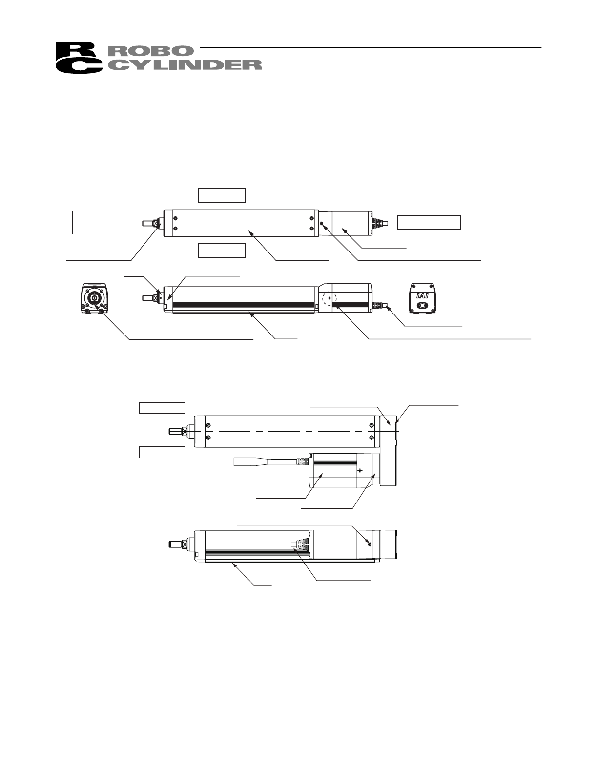
1. Motor Straight Type
Right Side
Opposite Side
of the Motor
Rod-Tip Adapter
Rod
Scraper (Oprtion equipped type)
Left Side
Front Housing
2. Motor Reversing Hollowed Shaft Type
Right Side
Left Side
Frame Cover
Base
Reversing Bracket
Motor Unit
Pulley Bracket
Screw for Motor Unit Attachment
Motor Side
Motor Unit
Screw for Motor Unit Attachment
Actuator Cable
Tapped Hole for Ground Cable Connection
Pulley Cover
Base
Actuator Cable
The direction of the motor is either left reversed: ML (shown in figure above) or right reversed: MR.
9
Page 16

1. Specifications Check
r
1.1 Checking the Product
The standard configuration of this product is comprised of the following parts.
See the component list for the details of the enclosed components. If you find any fault or missing parts, contact
your local IAI distributor.
1.1.1 Parts
No. Name Model number Quantity Remarks
1. Checking the Product
1 Actuator
Accessories
2 Motor • encoder cables
3 Homing stickers 1
4 Nut 1 Refer to list below
5 First Step Guide 1
6 Operation Manual (CD/DVD) 1
7 Safety Guide 1
Note1 The motor • encoder cables supplied vary depending on the controller used.
[Refer to 1.4, “Motor • Encoder Cables.”]
(Note1)
Refer to “How to Read the Model
Nameplate” and “How to Read the
Model Number.”
1
1
(List of Included Nut Type)
Model No.
RCP4–RA5C, RA5R 1
RCP4–RA6C, RA6R 1
Nut
(M10u1.25)
Nut
(M14u1.5)
1.1.2 Related Operation Manuals for the Each Controller Supported by this Product
Shown below is a list of the instruction manuals for the controllers related to this product which is recorded in
Instruction Manual (DVD).
No. Name Control No.
1
Operation Manual for PCON㵨CA Controller
2
Operation Manual for RC PC Software RCM㵨101㵨MW/RCM㵨101㵨USB
3
Operation Manual for CON㵨PTA/PDA/PGA
ME0289
ME0155
ME0295
1.1.3 How to Read the Model Nameplate
Model
Serial numbe
MODEL RCP4-RA5C-I-42P-3-50-P3-P-B
SERIAL No.000090266 MADE IN JAPAN
10
Page 17

1.1.4 How to Read the Model Number
RCP4 í RA5C í I í 42P í 3 í 50 í P3 í P í B í **
Series name
<Type>
Motor straight type
RA5C
RA6C
Motor Reversing type
RA5R
RA6R
<Encoder type>
I : Incremental
<Motor type>
42P : 42Ƒ
56P : 56Ƒ
<Lead>
RA5C, RA5R
3/6/12/20
RA6C,RA6R
4/8/16/24
Identification for IAI use only
(Note1)
<Options>
B : Brake
NM : Reversed-home specification
FL : Flange bracket (Front)
SC : Scraper
ML : Motor Left Reversed
MR : Motor Right Reversed
<Cable length>
N : None
P : 1m
S : 3m
M : 5m
XƑƑ : Length specification
RƑƑ : Robot cable
<Controller>
P3 : PCON-CA
<Stroke>
[Refer to 1.2 Specification]
1. Checking the Product
Note 1 Identification for IAI use only : It may be displayed for IAI use. It is not a code to show the model type.
11
Page 18

1.2 Specification
1.2.1 Speed
[When high–output setting is effective]
Size
1. Checking the Product
RA5C 42P
RA6C 56P
RA5R 42P
RA6R 56P
Motor
Type
Speed limits (Unit: mm/s)
Lead
Horizontal /
[mm]
Vertical
Horizontal 225
3
Vertical 225
Horizontal 450
6
Vertical 450
Horizontal 700
12
Vertical 700
Horizontal 800
20
Vertical 800
Horizontal 210
4
Vertical 210
Horizontal 420
8
Vertical 420
Horizontal 700
16
Vertical 560
Horizontal 800
24
Vertical 600
Horizontal 225
3
Vertical 225
Horizontal 450
6
Vertical 450
Horizontal 700
12
Vertical 700
Horizontal 800
20
Vertical 800
Horizontal 175
4
Vertical 175
Horizontal 420
8
Vertical 350
Horizontal 560
16
Vertical 560
Horizontal 800
24
Vertical 800
50 100 150 200 250 300 350 400 450 500
Stroke [mm]
12
Page 19

[When high–output setting is ineffective]
Strokes and maximum speed limits (Unit: mm/s)
Motor
Size
RA5C 42P
RA6C 56P
RA5R 42P
RA6R 56P
Type
Lead
Horizontal /
[mm]
Vertical
Horizontal 125
3
Vertical 125
Horizontal 250
6
Vertical 250
Horizontal 500
12
Vertical 500
Horizontal 640
20
Vertical 640
Horizontal 140
4
Vertical 140
Horizontal 210
8
Vertical 210
Horizontal 420
16
Vertical 420
Horizontal 600
24
Vertical 400
Horizontal 125
3
Vertical 125
Horizontal 250
6
Vertical 250
Horizontal 500
12
Vertical 500
Horizontal 640
20
Vertical 640
Horizontal 140
4
Vertical 140
Horizontal 210
8
Vertical 210
Horizontal 420
16
Vertical 420
Horizontal 600
24
Vertical 400
Stroke [mm]
50 100 150 200 250 300 350 400 450 500
1. Checking the Product
13
Page 20

1.2.2 Maximum Acceleration and Transportable Weight
If the transportable weight is smaller than as specified, the acceleration/deceleration can be raised beyond the
applicable level.
[When high–output setting for motor straight type is effective]
Type Motor Type
1. Checking the Product
RA5C 42P
Lead
[mm]
3
6
Horizontal
/ Vertical
Horizontal
Vertical
Horizontal
Vertical
Payload capacity by acceleration/deceleration [kg]
Velocity
[mm/s]
25 60 60 50 45 40
50 60 60 50 45 40
75 60 60 50 45 40
100 60 60 50 45 40
125 60 60 50 40 30
150 60 50 40 30 25
175 60 40 35 25 20
200 60 35 30 20 14
225 40 16 16 10 6
25 20 20 20 – –
50 20 20 20 – –
75 20 20 20 – –
100 20 20 20 – –
125 18 14 10 – –
150 14 10 6 – –
175 12 6 5 – –
200 8 5 4.5 – –
225 5 5 4 – –
50 40 40 35 30 25
100 40 40 35 30 25
150 40 40 35 25 25
200 40 40 30 25 20
250 40 40 27.5 22.5 18
300 40 35 25 20 14
350 40 30 14 12 10
400 30 18 10 6 5
450 25 8 3 – –
50 10 10 10 – –
100 10 10 10 – –
150 10 10 10 – –
200 10 10 10 – –
250 10 9 8 – –
300 6 6 6 – –
350 5 5 5 – –
400 4 3 3 – –
450 2 2 1 – –
0.1G 0.3G 0.5G 0.7G 1.0G
0 60 60 50 45 40
0 20 20 20 – –
0 40 40 35 30 25
0 10 10 10 – –
14
Page 21

Type Motor Type
RA5C 42P
Lead
[mm]
12
20
Horizontal
/ Vertical
Horizontal
Vertical
Horizontal
Vertical
Payload capacity by acceleration/deceleration [kg]
Velocity
[mm/s]
100 25 25 18 16 12
200 25 25 18 16 10
300 25 25 18 12 8
400 20 20 14 10 6
500 15 15 8 6 4
600 10 10 6 3 2
700 – 6 2
100 4 4 4
200 4 4 4
300 4 4 4
400 4 4 4
500 4 3.5 3
600 4 3 2
700 – 2 1
160 6 6 6 5 5
320 6 6 6 5 3
480 6 6 6 5 3
640 – 6 4 3 2
800 – 4 3
160 1.5 1.5 1.5
320 1.5 1.5 1.5
480 1.5 1.5 1.5
640 – 1.5 1.5
800 – 1 1
0.1G 0.3G 0.5G 0.7G 1.0G
0 25 25 18 16 12
– –
0 4 4 4
0 6 6 6 5 5
0 1.5 1.5 1.5
– –
– –
– –
– –
– –
– –
– –
– –
– –
– –
– –
– –
– –
– –
– –
1. Checking the Product
15
Page 22

Type Motor Type
1. Checking the Product
RA6C 56P
Lead
[mm]
4
8
Horizontal
/ Vertical
Horizontal
Vertical
Horizontal
Vertical
Payload capacity by acceleration/deceleration [kg]
Velocity
[mm/s]
35 80 80 70 65 60
70 80 80 70 65 60
105 80 80 60 50 40
140 80 50 30 20 15
175 50 15 – – –
210 20 – – – –
35 28 28 28 – –
70 28 28 28 – –
105 22 20 18 – –
140 16 12 10 – –
175 9 4 – – –
210 2 – – – –
70 60 60 50 45 40
140 60 60 50 45 40
210 60 60 40 31 26
280 60 34 22 15 11
350 60 14 5 1 –
420 15 1 – – –
70 18 18 18 – –
140 16 16 12 – –
210 10 10 9 – –
280 8 7 6 – –
350 3 3 2 – –
420 2 – – – –
0.1G 0.3G 0.5G 0.7G 1.0G
0 80 80 70 65 60
0 28 28 28 – –
0 60 60 50 45 40
0 18 18 18 – –
16
Page 23

Type Motor Type
RA6C 56P
Lead
[mm]
16
24
Horizontal
/ Vertical
Horizontal
Vertical
Horizontal
Vertical
Payload capacity by acceleration/deceleration [kg]
Velocity
[mm/s]
140 50 50 40 35 30
280 50 50 35 25 20
420 50 25 18 14 10
560 12 10 5 3 2
700 3 2 – – –
140 8 8 8 – –
280 8 7 7 – –
420 6 4.5 4 – –
560 4 2 1 – –
700 – – – – –
200 20 20 18 15 12
400 20 20 18 15 10
600 15 14 9 7 4
800 – 5 1 1 –
200 3 3 3 – –
400 3 3 3 – –
600 3 3 2 – –
800 – – – – –
0.1G 0.3G 0.5G 0.7G 1.0G
0 50 50 40 35 30
0 8 8 8 – –
0 20 20 18 15 12
0 3 3 3 – –
1. Checking the Product
17
Page 24

[When high–output setting for motor Reversing type is effective]
Type Motor Type
1. Checking the Product
RA5R 42P
Lead
[mm]
3
6
Horizontal
/ Vertical
Horizontal
Vertical
Horizontal
Vertical
Payload capacity by acceleration/deceleration [kg]
Velocity
[mm/s]
0.1G 0.3G 0.5G 0.7G 1.0G
0 60 60 50 45 40
25 60 60 50 45 40
50 60 60 50 45 40
75 60 60 50 45 40
100 60 60 50 45 40
125 60 60 50 40 30
150 60 50 40 30 25
175 60 40 35 25 20
200 60 35 30 20 14
225 40 16 16 10 6
0 20 20 20 – –
25 20 20 20 – –
50 20 20 20 – –
75 20 20 20 – –
100 20 20 20 – –
125 18 14 10 – –
150 14 10 6 – –
175 12 6 5 – –
200 8 5 4.5 – –
225 5 5 4 – –
0 40 40 35 30 25
50 40 40 35 30 25
100 40 40 35 30 25
150 40 40 35 25 25
200 40 40 30 25 20
250 40 40 27.5 22.5 18
300 40 35 25 20 14
350 40 30 14 12 10
400 30 18 10 6 5
450 25 8 3 – –
0 10 10 10 – –
50 10 10 10 – –
100 10 10 10 – –
150 10 10 10 – –
200 10 10 10 – –
250 10 9 8 – –
300 6 6 6 – –
350 5 5 5 – –
400 4 3 3 – –
450 2 2 1 – –
18
Page 25

Type Motor Type
RA5R 42P
Lead
[mm]
12
20
Horizontal
/ Vertical
Horizontal
Vertical
Horizontal
Vertical
Payload capacity by acceleration/deceleration [kg]
Velocity
[mm/s]
0.1G 0.3G 0.5G 0.7G 1.0G
0 25 25 18 16 12
100 25 25 18 16 12
200 25 25 18 16 10
300 25 25 18 12 8
400 20 20 14 10 6
500 15 15 8 6 4
600 10 10 6 3 2
700 – 6 2 – –
0 4 4 4 – –
100 4 4 4 – –
200 4 4 4 – –
300 4 4 4 – –
400 4 4 4 – –
500 4 3.5 3 – –
600 4 3 2 – –
700 – 2 1 – –
0 6 6 6 5 5
160 6 6 6 5 5
320 6 6 6 5 3
480 6 6 6 5 3
640 – 6 4 3 2
800 – 4 3 – –
0 1.5 1.5 1.5 – –
160 1.5 1.5 1.5 – –
320 1.5 1.5 1.5 – –
480 1.5 1.5 1.5 – –
640 – 1.5 1.5 – –
800 – 1 1 – –
1. Checking the Product
19
Page 26

Type Motor Type
1. Checking the Product
RA6R 56P
RA6R 56P
Lead
[mm]
4
8
16
24
Horizontal
/ Vertical
Horizontal
Vertical
Horizontal
Vertical
Horizontal
Vertical
Horizontal
Vertical
Payload capacity by acceleration/deceleration [kg]
Velocity
[mm/s]
0.1G 0.2G 0.3G 0.5G 0.7G
0 80 80 70 65 60
35 80 80 70 65 60
70 80 80 70 65 60
105 80 80 60 50 40
140 80 50 10 6 6
175 40 5 – – –
0 28 28 28 – –
35 28 28 28 – –
70 28 28 28 – –
105 22 20 18 – –
140 13 6 3 – –
175 4 – – – –
0 60 60 50 45 40
70 60 60 50 45 40
140 60 60 50 45 40
210 60 60 40 31 26
280 60 26 16 10 8
350 30 3 – – –
420 2 – – – –
0 18 18 18 – –
70 18 18 18 – –
140 16 16 12 – –
210 10 10 9 – –
280 8 5 3 – –
350 3 1 – – –
0 50 50 40 35 30
140 50 50 40 35 30
280 50 50 35 25 20
420 50 25 18 14 10
560 12 10 5 3 2
0 8 8 8 – –
140 8 8 8 – –
280 8 7 7 – –
420 4.5 4.5 4 – –
560 2 1 1 – –
0 20 20 18 15 12
200 20 20 18 15 12
400 20 20 18 15 10
600 15 14 9 7 4
800 – 3 1 – –
0 3 3 3 – –
200 3 3 3 – –
400 3 3 3 – –
600 3 3 2 – –
20
Page 27

[When high–output setting for motor straight type is ineffective]
Type Motor Type
RA5C 42P
Lead
[mm]
3
6
12
20
Horizontal /
Vertical
Horizontal
Vertical
Horizontal
Vertical
Horizontal
Vertical
Horizontal
Vertical
Payload capacity by acceleration/deceleration [kg]
Velocity
[mm/s]
0 – 40 – – –
25 – 40 – – –
50 – 40 – – –
75 – 40 – – –
100 – 40 – – –
125 – 40 – – –
0 – 20 – – –
25 – 20 – – –
50 – 16 – – –
75 – 12 – – –
100 – 9 – – –
125 – 5 – – –
0 – 40 – – –
50 – 40 – – –
100 – 40 – – –
150 – 40 – – –
200 – 35 – – –
250 – 10 – – –
0 – 10 – – –
50 – 10 – – –
100 – 10 – – –
150 – 8 – – –
200 – 5 – – –
250 – 3 – – –
0 – 25 – – –
100 – 25 – – –
200 – 25 – – –
300 – 20 – – –
400 – 10 – – –
500 – 5 – – –
0 – 4 – – –
100 – 4 – – –
200 – 4 – – –
300 – 3 – – –
400 – 2 – – –
500 – 1 – – –
0 – – 6 – –
160 – – 6 – –
320 – – 6 – –
480 – – 4 – –
640 – – 3 – –
0 – 1.5 – – –
160 – 1.5 – – –
320 – 1.5 – – –
480 – 1 – – –
640 – 0.5 – – –
0.1G 0.2G 0.3G 0.5G 0.7G
1. Checking the Product
21
Page 28

Type Motor Type
1. Checking the Product
RA6C 56P
Lead
[mm]
4
8
16
24
Horizontal /
Vertical
Horizontal
Vertical
Horizontal
Vertical
Horizontal
Vertical
Horizontal
Vertical
Payload capacity by acceleration/deceleration [kg]
Velocity
[mm/s]
0 – 55 – – –
35 – 55 – – –
70 – 55 – – –
105 – 55 – – –
140 – 35 – – –
0 – 26 – – –
35 – 26 – – –
70 – 15 – – –
105 – 4 – – –
140 – 2 – – –
0 – 50 – – –
70 – 50 – – –
140 – 50 – – –
210 – 30 – – –
0 – 17.5 – – –
70 – 17.5 – – –
140 – 7 – – –
210 – 2 – – –
0 – 40 – – –
140 – 40 – – –
280 – 30 – – –
420 – 15 – – –
0 – 5 – – –
140 – 5 – – –
280 – 3 – – –
420 – 1 – – –
0 – – 18 – –
200 – – 18 – –
400 – – 10 – –
600 – – 1 – –
0 – 3 – – –
200 – 3 – – –
400 – 2 – – –
600 – – – – –
0.1G 0.2G 0.3G 0.5G 0.7G
22
Page 29

[When high–output setting for motor reversing type is ineffective]
Type Motor Type
RA5R 42P
Lead
[mm]
3
6
12
20
Horizontal
/ Vertical
Horizontal
Vertical
Horizontal
Vertical
Horizontal
Vertical
Horizontal
Vertical
Payload capacity by acceleration/deceleration [kg]
Velocity
[mm/s]
0.1G 0.2G 0.3G 0.5G 0.7G
0 – 40 – – –
25 – 40 – – –
50 – 40 – – –
75 – 40 – – –
100 – 40 – – –
125 – 40 – – –
0 – 20 – – –
25 – 20 – – –
50 – 16 – – –
75 – 12 – – –
100 – 9 – – –
125 – 5 – – –
0 – 40 – – –
50 – 40 – – –
100 – 40 – – –
150 – 40 – – –
200 – 35 – – –
250 – 10 – – –
0 – 10 – – –
50 – 10 – – –
100 – 10 – – –
150 – 8 – – –
200 – 5 – – –
250 – 3 – – –
0 – 25 – – –
100 – 25 – – –
200 – 25 – – –
300 – 20 – – –
400 – 10 – – –
500 – 5 – – –
0 – 4 – – –
100 – 4 – – –
200 – 4 – – –
300 – 3 – – –
400 – 2 – – –
500 – 1 – – –
0 – – 6 – –
160 – – 6 – –
320 – – 6 – –
480 – – 4 – –
640 – – 3 – –
0 – 1.5 – – –
160 – 1.5 – – –
320 – 1.5 – – –
480 – 1 – – –
640 – 0.5 – – –
1. Checking the Product
23
Page 30

Type Motor Type
1. Checking the Product
RA6R 56P
Lead
[mm]
4
8
16
24
Horizontal
/ Vertical
Horizontal
Vertical
Horizontal
Vertical
Horizontal
Vertical
Horizontal
Vertical
Payload capacity by acceleration/deceleration [kg]
Velocity
[mm/s]
0.1G 0.2G 0.3G 0.5G 0.7G
0 – 55 – – –
35 – 55 – – –
70 – 55 – – –
105 – 55 – – –
140 – 5 – – –
0 – 26 – – –
35 – 26 – – –
70 – 15 – – –
105 – 4 – – –
140 – 0.5 – – –
0 – 50 – – –
70 – 50 – – –
140 – 50 – – –
210 – 30 – – –
0 – 17.5 – – –
70 – 17.5 – – –
140 – 7 – – –
210 – 2 – – –
0 – 40 – – –
140 – 40 – – –
280 – 30 – – –
420 – 6 – – –
0 – 5 – – –
140 – 5 – – –
280 – 3 – – –
420 – 0.5 – – –
0 – – 18 – –
200 – – 18 – –
400 – – 10 – –
600 – – 1 – –
0 – 3 – – –
200 – 3 – – –
400 – 2 – – –
600 – – – – –
Caution: Do not set speeds and accelerations/decelerations equal to or greater than the respective ratings.
Doing so may result in vibration, failure or shorter life.
If any acceleration/deceleration equal to or greater than the rated acceleration/deceleration is set,
a creep phenomenon or slipped coupling may occur.
24
Page 31

1.2.3 Driving System • Position Detector
Type Motor Type Lead
3
RA5C
RA5R
RA6C
RA6R
42P
56P
6
12
20
4
8
16
24
No. of
Encoder
Pulses
800
Type Diameter Accuracy
Rolled
Rolled
Ball Screw Type
I10mm
I12mm
1.2.4 Positioning Precision
Type lead Item Tolerance
RA5C
RA5R
RA6C
RA6R
This is an option already attached when it is shipped out from the factory.
It does not include the consideration of time-dependent change as it is used.
3, 6, 12
20
4, 8, 16
24
Positioning repeatability
Backlash
Positioning repeatability
Backlash
Positioning repeatability
Backlash
Positioning repeatability
Backlash
±0.02mm
0.1mm or less
±0.03mm
0.1mm or less
±0.02mm
0.1mm or less
±0.03mm
0.1mm or less
1. Checking the Product
C10
C10
25
Page 32

1.2.5 Current Limit Value and Pressing Force
Ɣ RA5C, RA5R
Current Limit Value Lead 3 Lead 6 Lead 12 Lead 20
1. Checking the Product
* These are the reference values at 20mm/s of pressing speed.
[N]
20% 106 53 26 16
30% 159 79 40 24
40% 211 106 53 32
50% 264 132 66 40
60% 317 159 79 48
70% 370 185 93 56
RA5C, RA5R Current Limiting Values and Pressing Force
400
350
300
Lead 3
250
200
150
100
Pressing Force [N]
50
0
0 10 20 30 40 50 60 70 80
Lead 6
Lead 12
Lead 20
Current-Limiting Value [%]
26
Page 33

Ɣ RA6C, RA6R
* These are the reference values at 20mm/s of pressing speed.
Current Limit Value Lead 4 Lead 8 Lead 16 Lead 24
20% 312 156 78 52
30% 469 234 117 78
40% 625 312 156 104
50% 781 391 195 130
60% 937 469 234 156
70% 1094 547 273 182
RA6C, RA6R Current Limiting Values and Pressing Force
1200
1000
[N]
1. Checking the Product
800
Lead 4
600
Lead 8
400
Pressing Force [N]
Lead 16
200
Lead 24
0
0 10 20 30 40 50 60 70 80
Current-Limiting Value [%]
Caution: (1) The relation of the pressing force and current limiting value is a reference. There will be a little
variance in the actual pressing force.
(2) If the current limiting value is low, the pressing force may largely vary.
(3) The movement speed at the pressing operation is fixed to 20mm/s.
The graph shows the values when pressing with 20mm/s, and it differs if the speed changes.
27
Page 34

1.2.6 Allowable Load and Torque on Rod Tip
Ɣ RCP4㵨RA5C/RA6C/RA5R/RA6R actuator possesses a built㵨in guide structure that enables it to apply a side㵨
way load (radial load) and torque. Make sure not to exceed the load indicated in the specification table.
Applying excess load may cause an operation failure, parts malfunction and shortened life.
1. Checking the Product
Should be below allowable load
Do not attempt to apply impact load
Should be below allowable torque
RCP4㵨RA5
Item Stroke 50 100 150 200 250 300 350 400
Rod Tip Allowable Static Load [N] 65.6 51.2 41.7 34.9 29.8 25.7 22.4 19.7
Load Offset Distance
[N]
(Operating life 5000km
Remaining Probability 90%)
Load Offset Distance
(Center of overhang load gravity)
Rod Tip Allowable Static Torque [N•m] 6.6 5.2 4.3 3.7 3.2 2.8 2.6 2.3
Rod Tip Dynamic Static Torque [N•m] 2.6 2.0 1.6 1.3 1.0 0.9 0.7 0.6
Rod Non㵨Rotation Accuracy
(Note 1)
0 mm
Load Offset Distance
[N]
0 mm
[mm] 100 or less
[deg] 0
32.4 23.6 18.1 14.4 11.6 9.5 7.7 6.2 Rod Tip Dynamic Static Load
25.6 19.7 15.7 12.7 10.4 8.6 7.1 5.7
RCP4㵨RA6
Item Stroke 50 100 150 200 250 300 350 400 450 500
Rod Tip Allowable Static Load [N] 112.7 91.5 76.7 65.7 57.25 50.4 44.8 40.2 36.2 32.7
Load Offset Distance
Rod Tip Dynamic Static Load
(Operating life 5000km
Remaining Probability 90%)
Load Offset Distance
(Center of overhang load gravity)
Rod Tip Allowable Static Torque [N•m] 11.4 9.3 7.9 6.8 6.0 5.4 4.9 4.5 4.1 3.8
Rod Tip Dynamic Static Torque [N•m] 3.9 3.1 2.5 2.1 1.8 1.5 1.3 1.1 1.0 0.8
Rod Non㵨Rotation Accuracy
(Note 1)
[N]
0 mm
Load Offset Distance
[N]
0 mm
[mm] 100 or less
[deg] 0
49.0 37.4 29.9 24.5 20.4 17.1 14.5 12.3 10.3 8.6
38.7 31.0 25.5 21.4 18.1 15.4 13.2 11.2 9.5 8.0
(Note 1) It shows the displacement angle in the rod rotational direction at no load.
28
Page 35

1.2.7 Rod Flexure (Reference)
(Note) This is the flexure of the rod when the actuator is installed vertically.
It does not include the flexure caused by the weight of itself.
RCP4-RA5C, RA5R Rod Flexure (Reference)
Flexure [mm]
Tip Load [N]
1. Checking the Product
Home
Flexure [mm]
RCP4-RA6C, RA6R Rod Flexure (Reference)
Home
Tip Load [N]
29
Page 36

1.3 Options
1.3.1 Brake Type (Model: B)
The brake is a mechanism designed to prevent the rod from dropping on a vertically installed actuator when the
power or servo is turned OFF.
Use the brake to prevent the installed load, etc., from being damaged due to the falling rod.
1.3.2 Reversed–home Specification (Model: NM)
The standard home position is on the motor side. However, the motor position will be reversed if it is desirable in
1. Checking the Product
view of the layout of the system, etc.
(Note) The home position is adjusted at the factory before shipment. If you wish to change the home after the
delivery of your actuator, you must return the actuator to IAI for adjustment.
1.3.3 Flange Bracket (Front) (Model: FL)
This is the flange bracket to attach on the front of the main unit. The model code is indicated with FL.
1.3.4 Scraper (Model: SC)
It is attached on the part where the rod moves in and out to prevent dust from getting inside the unit from the
outside. (This is an option already attached when it is shipped out from the factory. It is necessary to dismantle
and assemble back if it is required to be attached afterwards.)
Scraper
1.3.5 Motor Left Reversed, Motor Right Reversed (Model No. : ML, MR)
From the view of the motor side, the type with the motor reversed to the left is ML, and the motor reversed to the
right is MR.
ML MR
(Left Reversed) (Right Reversed)
30
Page 37

1.4 Motor • Encoder Cables
1.4.1 Motor • Encoder Integrated Cables
CB㵨CA㵨MPAƑƑƑ
(25)(30)
Connector : 1-1827863-1
Contact : 1827570-2
Connection diagram
CN1
1-1827863-1(AMP)
Pin No. Pin No.
A1
B1
A2
B2
A3
B3
A4
B4
A6
B6
A7
B7
A8
B8
A5
B5
A9
B9
A10
B10
A11
B11
Symbol
φA/U
VMM/V
OR(AWG22/19)
GN(AWG22/19)
φ_A/W
φB/-
BR(AWG22/19)
VMM/-
GY(AWG22/19)
φ_B/-
RD(AWG22/19)
LS+/BK+
LS-/BK-
-/A+
-/A-
A+/B+
A-/B-
B+/Z+
B-/ZBK+/LS+
BK-/LSLS_GND
VPS
VCC
GND
―
FG
Color
BL(AWG22/19)
BK(AWG26)
YW(AWG26)
BL(AWG26)
OR(AWG26)
GN(AWG26)
BR(AWG26)
GY(AWG26)
RD(AWG26)
BL(AWG26)
OR(AWG26)
GN(AWG26)
BR(AWG26) BR(AWG26)
GY(AWG26)
RD(AWG26)
―
BK
1. Checking the Product
L
CN2
PADP-24V-1-S(JST)
Symbol
φA/U
1
VMM/V
2
φ_A/W
5
3
4
VMM/-
φ_B/-
6
LS+/BK+
7
8
LS-/BK-
11
-/A+
12
A+/B+
13
A-/B-
14
B+/Z+
15
B-/Z-
16
BK+/LS+
9
BK-/LS-
10
LS_GND
20
18
VPS
VCC
17
19
GND
21
22
23
24
(25) (15) (30)
Color
BL(AWG22/19)
OR(AWG22/19)
GN(AWG22/19)
φB/-
BR(AWG22/19)
GY(AWG22/19)
RD(AWG22/19)
BK(AWG26)
YW(AWG26)
BL(AWG26)
-/A-
OR(AWG26)
GN(AWG26)
BR(AWG26)
GY(AWG26)
RD(AWG26)
BL(AWG26)
OR(AWG26)
GN(AWG26)
GY(AWG26)
RD(AWG26)
―
―
―
FG
―
―
―
BK
CN2CN1
Connector : PADP-24V-1-S
Contact
SPND-002T-C0.5 (AWG26)
SPND-001T-C0.5 (AWG22)
31
Page 38

1.4.2 Motor • Encoder Integrated Cables Robot Type
CB㵨CA㵨MPAƑƑƑ㵨RB
Connector :
1-1827863-1
Contact :
1827570-2
1. Checking the Product
(30)
(25)
CN1
1-1827863-1(AMP)
Pin No.
Symbol
A1
B1
VMM/V
φ_A/W
A2
B2
A3
VMM/-
B3
A4
LS+/BK+
B4
LS-/BK-
A6
B6
A7
B7
A8
B8
A5
BK+/LS+
B5
BK-/LSLS_GND
A9
B9
A10
B10
A11
B11
φA/U
φB/-
φ_B/-
-/A+
-/A-
A+/B+
A-/B-
B+/Z+
B-/Z-
VPS
VCC
GND
―
FG
Color
BK(AWG22/19)
WT(AWG22/19)
BR(AWG22/19)
GN(AWG22/19)
YW(AWG22/19)
RD(AWG22/19)
OR
(AWG25)
GY
(AWG25)
WT
(AWG25)
YW
(AWG25)
RD
(AWG25)
GN
(AWG25)
BK
(AWG25)
BR
(AWG25)
BK
(AWG25)
BR
AWG25)
GN
(AWG25)
RD
(AWG25)
WT
(AWG25)
YW
(AWG25)
―
L
Connection diagram
PADP-24V-1-S (
Pin No.
11
12
13
14
15
16
10
20
18
17
19
21
22
23
24
1
2
5
3
4
6
7
8
9
CN2
Symbol
φA/U
VMM/V
φ_A/W
φB/-
VMM/-
φ_B/-
LS+/BK+
LS-/BK-
-/A+
-/A-
A+/B+
A-/B-
B+/Z+
B-/ZBK+/LS+
BK-/LS-
LS_GND
VPS
VCC
GND
―
―
―
FG
(25) (15) (30)
JST)
Color
BK(AWG22/19)
WT(AWG22/19)
BR(AWG22/19)
GN(AWG22/19)
YW(AWG22/19)
RD(AWG22/19)
OR
(AWG25)
GY
(AWG25)
WT
(AWG25)
YW
(AWG25)
RD
(AWG25)
GN
(AWG25)
BK(AWG25)
BR
(AWG25)
BK
(AWG25)
BR
(AWG25)
GN
(AWG25)
RD
(AWG25)
WT
(AWG25)
YW
(AWG25)
―
―
―
Shield
CN2CN1
Connector :
PADP-24V-1-S
Contact
SPND-002T-C0.5 (AWG26)
SPND-001T-C0.5 (AWG22)
32
Page 39

2. Installation
2.1 Transportation
[1] Handling of Robot
(1) Handling the Packed Unit
Unless otherwise specified, the actuator is shipped with each axis packaged separately.
Do not damage or drop. The package is not applied with any special treatment that enables it to resist
an impact caused by a drop or crash.
Transport a heavy package with at least more than two operators. Consider an appropriate method for
transportation.
Keep the unit in horizontal orientation when placing it on the ground or transporting. Follow the
instruction if there is any for the packaging condition.
Do not step or sit on the package.
Do not put any load that may cause a deformation or breakage of the package.
(2) Handling the Actuator After Unpacking
x Do not carry an actuator by motor unit and a cable or attempt to move it by pulling the cable.
2. Installation
x Hold the body base when transporting the actuator.
x Be careful not to bump the actuator into anything when moving it.
x Do not apply an excessive force to each part of the actuator.Inparticular, prevent the motor unit and rear
bracket from receiving an unnecessary force.
Supplement) For the names of each part of the actuator, refer to “Names of the Parts”
33
Page 40

[2] Handling in Assembled Condition
x When carrying the actuator, exercise caution not to bump it against nearby objects or structures.
x Secure the rods to prevent sudden movement during transport.
x If any end of the actuator is overhanging, secure it properly to avoid significant movement due to external
vibration.
x When transporting the assembly without the ends of the actuators fastened, do not subject the assembly to an
impact of 0.3 G or more.
x When suspending the mechanical equipment (system) with ropes, avoid applying force to actuator, connector
box, etc. Also, avoid the cables being pinched or caused an excessive deformation.
2. Installation
34
Page 41

2.2 Installation and Storage • Preservation Environment
[1] Installation Environment
The actuator should be installed in a location other than those specified below.
In general, the installation environment should be one in which an operator can work without protective gear.
Also provide sufficient work space required for maintenance inspection.
x Where the actuator receives radiant heat from strong heat sources such as heat treatment furnaces
x Where the ambient temperature exceeds the range of 0 to 40qC
x Where the temperature changes rapidly and condensation occurs
x Where the relative humidity exceeds 85% RH
x Where the actuator receives direct sunlight
x Where the actuator is exposed to corrosive or combustible gases
x Where the ambient air contains a large amount of powder dust, salt or iron (at level exceeding what is normally
expected in an assembly plant)
x Where the actuator is subject to splashed water, oil (including oil mist or cutting fluid) or chemical solutions
x Where the actuator receives impact or vibration
If the actuator is used in any of the following locations, provide sufficient shielding measures:
x Where noise generates due to static electricity, etc.
x Where the actuator is subject to a strong electric or magnetic field
x Where the actuator is subject to ultraviolet ray or radiation
[2] Storage • Preservation Environment
x The storage and preservation environment should comply with the same standards as those for the installation
environment. In particular, when the machine is to be stored for a long time, pay close attention to
environmental conditions so that no dew condensation forms.
x Unless specially specified, moisture absorbency protection is not included in the package when the machine is
delivered. In the case that the machine is to be stored and preserved in an environment where dew
condensation is anticipated, take the condensation preventive measures from outside of the entire package, or
directly after opening the package.
x For storage and preservation temperature, the machine withstands temperatures up to 60qC for a short time,
but in the case of the storage and preservation period of 1 month or more, control the temperature to 50�C or
less.
2. Installation
x Storage and preservation should be performed in the horizontal condition. In the case it is stored in the
packaged condition, follow the posture instruction if any displayed on the package.
35
Page 42

2.3 How to Installation
This chapter explains how to install the actuator on your mechanical system.
2.3.1 General Rules on Installation
Follow the information below when installing the actuator, as a rule.
Do pay attention to these items (except with custom-order models).
2. Installation
{ : Possible ٌ : Daily inspection is required u : Not possible
RA5C, RA6C
RA5R, RA6R
Model
Horizontal
installation
{ { { {
Vertical installation Sideway installation
Ceiling mount
installation
Horizontal Vertical Sideways Ceiling mount
Caution: When the unit is installed vertically oriented, attempt to put the motor up unless there is a special
reason. Putting the motor on the lower side would not cause a problem in an ordinary operation.
However, it may rarely cause a problem, when it is not operated for a long period, depending on
the surrounding environment (especially high temperature), caused by the grease being
separated and the base oil flowing into the motor unit.
36
Page 43

2.3.2 Installation of Main Unit
䎃
The surface to mount the main unit should be a machined surface or a plane that possesses an equivalent
accuracy and the flatness should be within 0.05mm. Also, the platform should have a structure stiff enough to
install the unit so it would not generate vibration or other abnormality.
䎃
Also consider enough space necessary for maintenance work such as actuator replacement and inspection.
On the base there is a datum surface prepared for the attachment slotted holes.
On the back side of the actuator, there are attachment tapped holes, through holes, positioning reamed holes and
slotted holes. For the details of the positions and dimensions, check in the appearance drawings. [Refer to 6.
External Dimensions.]
When repeatability in re-attaching is required after it is detached, utilize the reamed holes. Please note, however,
that a consideration is necessary such as to use only one point on the motor side of the reamed holes when a
fine-tuning such as perpendicularity is required.
[1] Using the Tapped Holes on the Bottom of the Base
This actuator has tapped holes for mounting so it can be fixed from the bottom of the base.
(Note that the tapped hole size depends on the model. Please see the diagrams below and 6. “External
Dimensions.”)
Also, there are reamed holes and a slotted hole for positioning pins.
2. Installation
Attachment Hole
Reamed Hole
Oblong Hole
Through Hole
Tightening Torque
Model
Name
RA5C
RA5R
RA6C
RA6R
Tapped
Hole Size
M4 7mm
M5 9mm
Tapped Holes Depth
In the case that steel
is used for the bolt
seating surface:
3.59N㨯m
(0.37kgf㨯m)
7.27N㨯m
(0.74kgf㨯m)
In the case that
aluminum is used for
the bolt seating
surface:
1.76N㨯m
(0.18kgf㨯m)
3.42N㨯m
(0.35kgf㨯m)
Reamer Hole [mm]
I4H7 Depth 5.5
I4H7 Depth 5.5
Tightening screws
x Use hexagonal socket head bolts for the male threads for installing the base.
x Use of high–tension bolts meeting at least ISO 10.9 is recommended.
x The length of thread engagement should be 1.8 times more than the nominal diameter, and pay attention not to
stick the screw out inside the actuator.
Caution: Be careful when selecting the bolt length. If bolts of inappropriate lengths are used, the tapped
holes may be damaged, actuator mounting strength may become insufficient, or contact with
driving parts may occur, resulting in lower precision or unexpected accidents.
37
Page 44

[2] Using the Mounting Holes on the Top of the Base
There are through holes equipped on the base so the unit can be attached from the top of the base.
Detach the side covers on both sides when installing.(Remove 4 hex socket head cap screws.)
Frame Cover
Mounting Screw
2. Installation
When affixing the frame cover, tighten the screws with the tightening torque described below.
䎃
Apply the socket head cap screw indicated in the table below suitable for the platform material.
䎃
Tightening screws
x Use hexagonal socket head bolts for the male threads for installing the base.
x Use of high–tension bolts meeting at least ISO 10.9 is recommended.
x For the effective engagement length between the bolt and female thread, provide at least the applicable value
specified below:
Female thread is made of steel material ĺ Same length as the nominal diameter
Female thread is made of aluminum ĺ 1.8 times of nominal diameter
Frame Cover
Mounting
Holes
Model Name Screw Diameter Tightening Torgue
RA5C
RA5R
RA6C
RA6R
Model
Name
RA5C
RA5R
RA6C
RA6R
I4.5 drilled hole, I8 counter boring depth 4.5
I4.5 drilled hole, I8 counter boring depth 4.5
M3 0.89N㨯m (0.9kgf㨯m)
M4 2.07N㨯m (0.21kgf㨯m)
Through Holes Mounting Screw Tightening Torque
M4
M4
Mounting
Screw
䎃
1.76N㨯m
(0.18kgf㨯m)
1.76N㨯m
(0.18kgf㨯m)
Caution: Pay attention when choosing the screw length. In case that insufficient length of screws is chosen,
it may cause such problems as the strength not being enough on the actuator attachment,
interference with driving part, drop in accuracy performance and unexpected accidents.
38
Page 45

[3] When using Tapped Holes on Front Housing
䎃
There are tapped holes equipped on the front housing.
Utilize these tapped holes for installation.
The effective depth for the attachment screws is as shown below;
䎃
䎃
Model Name Tapped Hole Size B A Screw Effective Depth
RA5C
RA5R
RA6C
RA6R
M6 39 12
M8 43 16
Tightening Torque
In the case that steel is
used for the bolt
seating surface:
12.3N㨯m
(1.26kgf㨯m)
30N㨯m
(3.1kgf㨯m)
2. Installation
In the case that
aluminum is used for
the bolt seating
surface:
5.4N㨯m
(0.55kgf㨯m)
11.5N㨯m
(1.2kgf㨯m)
Make sure to follow “[6] Caution for Installation using Front Housing and Front Flange”
Tightening screws
x Use hexagonal socket head bolts for the male threads for installing the base.
x Use of high–tension bolts meeting at least ISO 10.9 is recommended.
x Have the length of thread engagement approximately 1.8 times of the nominal diameter.
Caution: Pay attention when choosing the screw length. In case that insufficient length of screws is chosen,
it may cause such problems as the strength not being enough on the actuator attachment,
interference with driving part, drop in accuracy performance and unexpected accidents.
39
Page 46

[4] When using Front Flange (Option)
There are holes for attachment on the front flange. Utilize these holes for the installation.
The attachment holes are located as shown below;
䎃
䎃
䎃
䎃
2. Installation
䎃
䎃
䎃
䎃
䎃
䎃
䎃
䎃
䎃
䎃
䎃
䎃
䎃
䎃
䎃
Model Name Applicable Screw Diameter A B C D
RA5C/RA5R Front Flange M6 65 30 10
RA6C/RA6R Front Flange M8 76 33 12
I6.6
I9
䎃
䎃
Make sure to follow “[6] Caution for Installation using Front Housing and Front Flange”
䎃
䎃
Tightening screws
x Use hexagonal socket head bolts for the male threads for installing the base.
x Use of high–tension bolts meeting at least ISO 10.9 is recommended.
x For the effective engagement length between the bolt and female thread, provide at least the applicable value
specified below:
Female thread is made of steel material ĺ Same length as the nominal diameter
Female thread is made of aluminum ĺ 1.8 times of nominal diameter
䎃
Caution: Pay attention when choosing the screw length. In case that insufficient length of screws is chosen,
it may cause such problems as the strength not being enough on the actuator attachment,
interference with driving part, drop in accuracy performance and unexpected accidents.
40
Page 47

䃁 Caution for Installation using Front Housing and Front Flange
䎃
䎃
䎃
䎃
䎃
Do not attempt to apply any external force to the body when installing with front housing or front flange (option).
External force may cause an operation failure or parts malfunction.
External
Force
External
Force
2. Installation
䎃
Prepare a support block as shown in the figure below for the horizontal installation of the unit with its stroke more
than 150 even if there is no external force applied on the body. Even for those with the stroke less than 150, it is
recommended to have a support block to avoid vibration being generated due to the operation condition or
installation environment, which may cause an operation failure or parts malfunction.
Support Block
41
Page 48

[5] When Utilizing Attachment Holes on the Bracket for Motor-Reversed Type䎃
䎃
䎃
There are tapped holes prepared on the reversing bracket. (See the table below for the detailed dimensions.)
䎃
䎃
䎃
䎃
䎃
䎃
2. Installation
䎃
䎃
䎃
䎃
䎃
Tightening screws
x For attaching using male screw, use a hex socket cap screw.
x It is recommended to use high-tensile bolts with ISO-10.9 or more.
x Make sure to have the effective length of thread engagement at least approximately 1.8 times of the nominal
diameter of bolts and screws.
䎃
Model Name Attachment Holes
RA5R M5 15mm
RA6R M6 14mm
Attachment Hole
Depth
A B C
RA5R 37 29.5 M5 Depth 15
RA6R 48 33 M6 Depth 14
Tightening Torque
3.42N䱏m
(0.35kgf䱏m)
5.36 N䱏m
(0.55kgf䱏m)
Caution: Pay attention when choosing the screw length. In case that insufficient length of screws is chosen,
it may cause such problems as the strength not being enough on the actuator attachment,
interference with driving part, drop in accuracy performance and unexpected accidents.
[Precautions for Attachments]
Please note the following caution notes when installing the unit with using the tapped holes on the reversing
bracket.
Do not attempt to affix the unit only with the tapped holes on the reversing bracket.
Do not apply external force to the main body.
There may be caused vibration due to the operating condition or installation environment, which may result in
operational failures or components malfunction.
42
Page 49

Availability of installation for each installation posture is as shown below:
(Note) When it is perpendicular installation without support etc., external force does not act, it is not attempt to
apply the radial load.
䎃
䎃
䎃
䎃
䎃
䎃
䎃
䎃
䎃
Horizontal
䎃
䎃
䎃
䎃
Horizontal Vertical Mount
䎃
䎃
䎃
Installation Posture
u
¨
{ {
Supports
u
u
With No Supported
With Support
䎃
䎃
䎃
䎃
䎃
Vertical
Mount
䎃
When using the unit in the horizontal or vertical orientation, have a pedestal to support the body to avoid
external force being applied to the unit.
2. Installation
Support Block
䎃
䎃
䎃
䎃
䎃
䎃
䎃
43
Page 50

[6] Attachment of Work Part (Transported Object)
䎃
䎃
Utilize the threaded part on the rod tip to attach the work part (transported object). In the installation process,
make sure to hold 2 faces on the tip with a wrench so the tightening torque would not be applied to the rod.
[7] Mounting
x The platform to install the actuator should possess a structure that ensures enough stiffness, and should be
free from vibration.
2. Installation
x The surface where the actuator will be mounted should be a machined surface or that with an accuracy
equivalent to it, and the flatness should be 0.05mm/m or below.
x Ensure a room for maintenance work.
x The side and bottom surfaces of the base on the actuator work as the datum surfaces for the side of the rod.
x Use these surfaces as the datum surfaces for mounting.
Surface
Datum Surface Datum Surface
44
Follow the diagram below when installing the device using the reference surface.
R0.3 or less
Model Name A Dimensions [mm]
RA5/6 2 to 4 or less
Page 51
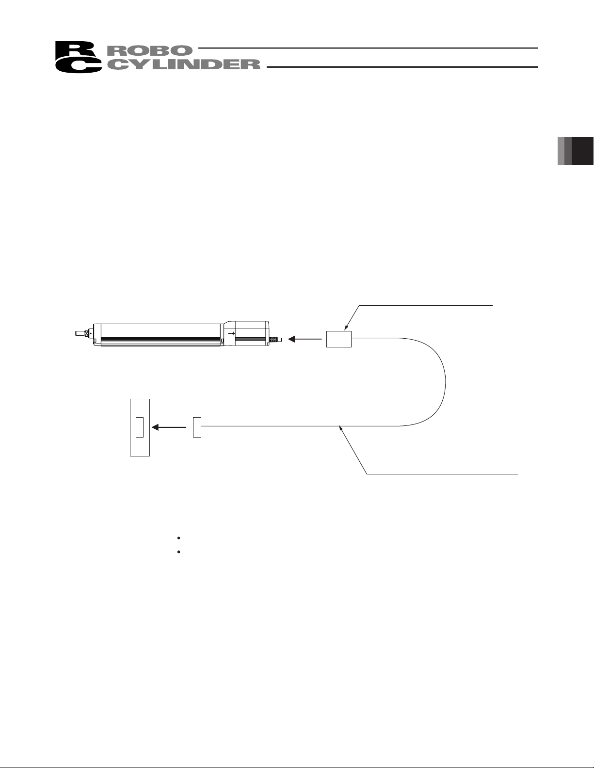
3. Connecting with Controller
As the connection cable for the controller and RCP4 (this actuator), use the IAI-dedicated controller and
dedicated connection cable.
This section explains the wiring method for a single axis.
x If the dedicated connection cable cannot be secured, reduce the load on the cable by allowing it to deflect only
by the weight of the cable or wire it in a self–standing cable hose, etc., having a large radius.
x Do not cut and reconnect the dedicated connection cable for extension or shorten the cable.
x Do not pull on the dedicated connection cable or bend it forcibly.
x The actuator cable coming out of the motor unit is not meant to be bent. Fix the cable so it would not be bent
repeatedly.
Please consult with IAI if you require a different kind of cable than the one supplied.
Dedicated Connection Cable
RCP4-XX
(connects controller and RCP4)
3. Connecting with Controller
Dedicated Controller
• PCON-CA
Dedicated Connection Cable
*) □□□indicates the cable length. Up to 20m can be specified.
Robot Cable
r=84mm or mere (Movable Use)
Standard cable
r=84mm or mere (Fixed Use)
Motor-encoder cable: CB-CA-MPA□□□
Motor-encoder cable robot cable: CB-CA-MPA□□□- RB
Example) 080 = 8 m
45
Page 52

Warning: For wiring, please follow the warnings stated below. When constructing a system
• Use dedicated cables of IAI indicated in this instruction manual. Contact us if you wish to
have a change to the specifications of the dedicated cables.
• Make sure to turn the power off in the process of power line or cable connection or
disconnection.
• Do not attempt to cut a dedicated cable with connectors on both ends to extend, shorten
or re-joint it.
• Hold the dedicated cable to avoid mechanical force being applied to the terminals and
connectors.
• Use a cable pipe or duct to have an appropriate protection when there is a possibility of
mechanical damage on a dedicated cable.
3. Connecting with Controller
• In case a dedicated cable is to be used at a moving part, make sure to lay out the cable
without applying any force to pull the connector or extreme bend on the cable. Do not
attempt to use the cable with a bending radius below the allowable value.
• Make certain that the connectors are plugged properly. Insufficient connection may cause
an operation error, thus it is extremely risky.
• Do not lay out the cables to where the machine runs over them.
as the machinery equipment, pay attention to the wiring and connection of each
cable so they are conducted properly. Not following them may cause not only a
malfunction such as cable breakage or connection failure, or an operation error,
but also electric shock or electric leakage, or may even cause a fire.
• Pay attention to the cable layout so it would not hit peripherals during an operation. In
case it does, have an appropriate protection such as a cable track.
• When a cable is used hanging on the ceiling, prevent an environment that the cable
swings with acceleration or wind velocity.
• Make sure there is not too much friction inside the cable storage equipment.
• Do not apply radiated heat to power line or cables.
x Do not bend the cable in the area from the connector tip inward to 150mm on both ends.
CB㵨CA㵨MPAƑƑƑ, CB㵨CA㵨MPAƑƑƑ㵨RB
150mm 150mm
• Have a sufficient radius for bending, and avoid a bend concentrating on one point.
Steel Strap
(Piano Wire)
Tie them up softly.
46
Page 53

• Do not let the cable bend, kink or twist.
• Do not pull the cable with a strong force.
• Pay attention not to concentrate the twisting force to one point on a cable.
3. Connecting with Controller
• Do not pinch, drop a heavy object onto or cut the cable.
• When a cable is fastened to affix, make sure to have an appropriate force and do not
tighten too much.
Do not use spiral tube in any
position where cables are bent
frequently.
47
Page 54

• PIO line, communication line, power and driving lines are to be put separately from each
other and do not tie them together. Arrange so that such lines are independently routed in
the duct.
• If using a cable track, arrange the wiring so that there is no entanglement or kink of the
cables in the cable carrier or flexible tube, and do not bind the cables so that the cables
are relatively free. (Arrange the wiring so the cables are not to be pulled when bent.)
3. Connecting with Controller
• The occupied volume rate for the cables, etc., inside the cable track should be 60% or
less.
Power Line
Duct
I/O Line
(Flat Cable, etc.)
Cable Track
Cable
48
Page 55

4. Caution for Operation
䎃
g
x When the reaction force against the pressing operation is the side㵨way force, make sure it would not exceed
the allowable load.
4. Caution for Operation
Be careful on the direction of the reaction force a
x When connecting the rod to external guides, be careful on the parallelism of the guides to the rod. When
connecting and fixing the rod to external guides, be careful not to apply excess side㵨way load to the rod
because of the assembly variation. For the connection of the rod and guides, have a component such as a free
joint to accept the assembly variation.
ainst the pressing operation.
External Guide
49
Page 56

x When using a stroke of more than 200 and the load is eccentric (offset), the rod may generate vibration in some
operation conditions. Apply guides to control the vibration.
4. Caution for Operation
50
Page 57

5. Maintenance Inspection
5.1 Inspection Items and Schedule
Follow the maintenance inspection schedule below.
It is assumed that the equipment is operating 8 hours per day.
If the equipment is running continuously night and day or otherwise running at a high operating rate, inspect more
often as needed.
Start of work inspection
1–month inspection
3–month inspection
Every 3 months since
6–month inspection
or every 5000km of
operated distance
Every 1 year since
External visual
inspection
{
{
{
{
{ {
{ {
Internal inspection Greasing
{ (Rod sliding surface)
{ (Rod sliding surface)
{(Ball Screw/Guide )
{(Ball Screw/Guide)
5.2 External Visual Inspection
An external visual inspection should check the following things.
Main unit Loose actuator mounting bolts, other loose items
Rod Lubrication, dust, foreign object on sliding surfaces
Scraper (optional equipment)
Cables Scratches, proper connections
Overall Irregular noise, vibration
* Scraper (optional equipment) is an expendable part. It may be shortened depending on the use environment or
operating condition, thus replace the scraper as soon as an abnormality is found.
Damage, crack, scratch, wear㵨out
5. Maintenance Inspection
5.3 Cleaning
Ɣ Clean exterior surfaces as necessary.
Ɣ Use a soft cloth to wipe away dirt and buildup.
Ɣ Do not blow too hard with compressed air as it may cause dust to get in through the gaps.
Ɣ Do not use oil–based solvents as they can harm lacquered and painted surfaces.
Ɣ To remove severe buildup, wipe gently with a soft cloth soaked in a neutral detergent or alcohol.
51
Page 58

5.4 Internal Inspections
Turn OFF the power, remove the side cover and have a visual inspection.
When inspecting the interior, check the following items.
Main unit Loose mounting bolts, other loose items
Guide section Lubrication, buildup
Ball screw Lubrication, buildup
Visually inspect the interior of the equipment. Check whether dust or other foreign matter has gotten inside and
check the lubrication state.
The lubrication may have turned brown. This is not a problem as long as the travel surfaces shine as though they
are wet.
If the grease is mixed with dust and does not have a shiny appearance, or if the grease has lost its efficacy due to
prolonged use, then clean each section and reapply grease.
The procedure for internal inspections is outlined below.
1) With 2.5mm (RA5C, RA5R) or with 3mm (RA6C, RA6R) hex wrench, loosen the screws holding the frame
cover, and detach the frame cover.
2) Check inside.
5. Maintenance Inspection
Extend the rod when checking the ball screw. The ball screw will appear. Slide the rod manually with hand or
move it with JOG operation of the controller.
3) After finishing the inspection, assemble back in the reverse order.
Frame Cover
Cover
Mounting Screw
Ball Screw
Guide
Rod
52
Page 59

5.5 Internal Cleaning
䎃
Ɣ Use a soft cloth to wipe away dirt and buildup.
Ɣ Do not blow too hard with compressed air as it may cause dust to get in through the gaps.
Ɣ Do not use oil–based solvents, neutral detergent or alcohol.
5.6 Grease Supply
5.6.1 What Grease to Use on the Guides
IAI uses the following grease in our plant.
Guide Idemitsu Kosan Daphne Eponex Grease No. 2
Other companies also sell similar types of grease. For details, give the above grease name to the manufacturer
you want to purchase from and ask what corresponding product they have available.
Here are some examples of similar products.
Showa Shell Oil Albania Grease No. 2
Mobil Oil Mobilax 2
Warning: Never use anything other than synthetic poly– olefin grease. Mixing poly– grease with other
grease not only reduces the performance of the grease, it may even cause damage to the
actuator.
5.6.2 What Grease to Use on the Ball Screw
IAI uses the following grease in our plant.
5. Maintenance Inspection
Ball Screw Kyodo Yushi Multitemp LRL 3
Warning: Never use anything other than synthetic poly– olefin grease. Mixing poly– grease with other
grease not only reduces the performance of the grease, it may even cause damage to the
actuator.
53
Page 60

5.6.3 Grease to be applied on the Rod (Sliding Surface)
The following grease is applied when the product is shipped out from IAI factory.
Rod (sliding surface) Kyodo Yushi Multitemp LRL 3
When supplying the grease, use the lithium㵨based all㵨around grease (consistency class: NLGI 2 to 0).
Caution: If the unit is equipped with the scraper (optional equipment), apply the grease on the rod sliding
surface inside the main unit.
Even if the grease is applied on the rod sliding surface outside the main unit, the scraper sweeps
out the grease, thus the grease would not be applied evenly throughout the whole area of the
shaft holder or the sliding surface.
5. Maintenance Inspection
54
Page 61

5.6.4 How to apply grease
(1) With 2.5mm (RA5C, RA5R) or with 3mm (RA6C, RA6R) hex wrench, loosen the screws holding the frame
cover, and detach the frame cover.
Frame Cover
Cover
Mounting Screw
Ball Screw
Guide
Rod
5. Maintenance Inspection
(2) Pull out the rod. The ball screw will appear.
For some of the low lead actuators, the rod would not move manually with hand.
Move it with JOG operation of the controller.
Rod
Ball Screw
55
Page 62

(3) After cleaning up the guide on both sides, apply the grease. Slide the rod back and forth to evenly apply the
grease. Wipe off the excess grease at last.
(4) After cleaning up the ball screw, apply the grease with hand.
5. Maintenance Inspection
Move the rod back and forth to evenly apply the grease.
For some of the low lead actuators, the rod would not move manually with hand.
Move it with JOG operation of the controller.
Wipe off the excess grease at last.
Guide
Guide
Ball Screw
56
Page 63
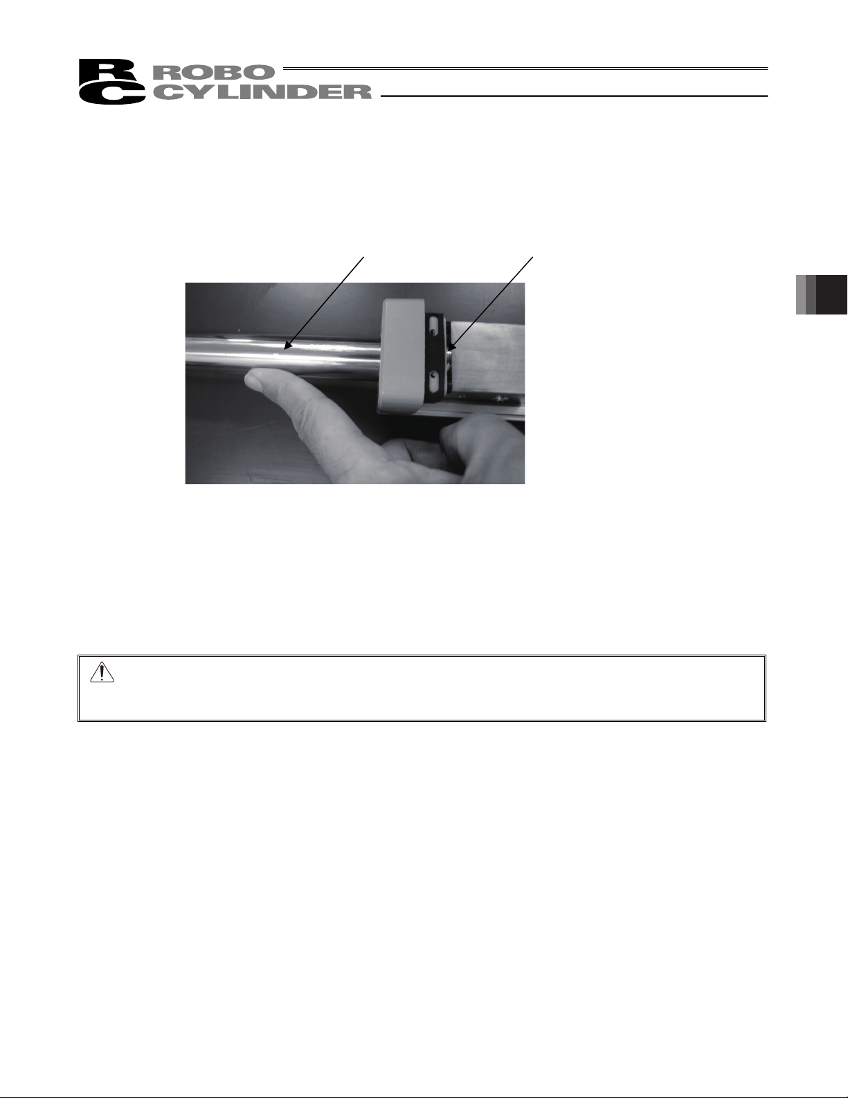
(5) If the unit is not equipped with the scraper (option), clean up the rod (sliding surface) and apply the grease
with hands.
Move the rod back and forth to evenly apply the grease.
For some of the low lead actuators, the rod would not move manually with hand.
Move it with JOG operation of the controller.
Wipe off the excess grease at last.
Rod (sliding surface) Inside of rod (sliding surface)
If the unit is equipped with the scraper (optional), apply the grease on the rod sliding surface inside the main
unit.
Even if the grease is applied on the rod sliding surface outside the main unit, the scraper sweeps out the
grease, thus the grease would not be applied evenly throughout the whole area of the shaft holder or the
sliding surface.
5. Maintenance Inspection
(6) After supplying the grease, attach the frame cover.
Caution: In case the grease got into your eye, immediately go see the doctor to get appropriate care.
After finishing the grease supply work, wash your hands carefully with water and soap to rinse
the grease off.
57
Page 64

5.7 Procedure for Belt Replacement and Tuning
Applicable Untis : RCP4-RA5R, RA6R
5.7.1 Inspection of the Belt
For inspection work, detach the pulley cover with 1.5mm-sized hex wrench and carry it out by visual.
Pulley Cover
Screw
5. Maintenance Inspection
The replacement period cannot be determined in general because the durability of the deceleration belt can be
greatly influenced by the conditions of operation.
It generally has life of hundreds of times for bending movement.
The timing belt requires replacement regularly under the following conditions as a reference since degradation
such as abrasion proceeds as the time passes for usage.
x When remarkable abrasion is confirmed on the teeth or edges of the belt
x When the belt is swelled for such reasons as oil being attached on
x When damage is confirmed such as crack on the tooth or back of the belt
Also, since it is difficult to confirm the degradation of the core wires to retain the strength of the teethed belt by
visual or looseness caused by being elongated, it is recommended to set regular replacement periods in advance
in case the product is used under such conditions that gives the core wires great fatigue due to high acceleration
and deceleration speed.
5.7.2 Belts to be used
The following belt is applied when the product is shipped out from IAI factory.
RA5R x 60S2M196GB Rubber Bare back type (Mitsuboshi Belting Ltd.)
RA6R x 100S3M237GB Rubber Bare back type (Mitsuboshi Belting Ltd.)
58
Page 65

5.7.3 Replacement of the Belt
[Items Required for Replacemet Work]
x Belt for Replacement
x Hex wrench
1.5mm, 2.5mm (RA5R) or 3mm (RA6R) - sized
x Tension gauge (that is available for pulling with 80N)
x Long cable band (thin string)
[Procedures]
1) Remove the three screws holding the pulley cover with a 1.5mm-sized hex wrench to detach the pulley cover.
Pulley Cover
Screw
5. Maintenance Inspection
2) Loosen the four screws holding the pulley on the motor side with a 2.5mm-sized (RA5R) or 3mm-sized (RA6R)
hex wrench.
If the belt is required to be replaced, replace it.
Belt
Screw
59
Page 66

3) Adjust the belt tension.
Hand a cable band (thin string) on the edge of the motor unit and pull it on a tension gauge with the specified load
(specified value of the belt tension).
When the load reached the specified, tighten the screws with a 2.5mm-sized (RA5R) or 3mm-sized (RA6R) hex
wrench to hold the unit in the place.
Belt Tension
5. Maintenance Inspection
4) Tighten the three screws to hold the pulley cover with a 1.5mm-sized hex wrench to attach the pulley cover.
Cable band (thin string)
Screw
Belt Tension
Belt Tension
RA5R 25 to 30N
RA6R 80 to 90N
RA5R Tightening Torque : 162 N • cm
RA䋶R
Tightening Torque : 323 N • cm
60
Pulley Cover
Screw
Tightening Torque : 25.4 N • cm
Page 67

5.8 Motor Replacement Process
5.8.1 RCP4-RA5C, RA6C
[Items required for replacing the motor]
x Motor Unit for Replacement
x Hex wrench set
3mm-sized
[Procedure]
5. Maintenance Inspection
1) Remove the screw affixing the actuator and the motor unit with a 3mm hex wrench.
For Fixed screws actuator and Motor Unit
2) Detach the motor unit.
61
Page 68

3) Make the profiles on the actuator side and motor unit side aligned so the projection matches to the slit.
4) Attach the motor unit for replacement with the projection being matched with the slit.
5. Maintenance Inspection
5) Tighten the screw to affix the motor unit to the actuator with 3mm hex wrench.
Make the projection and slit matched
with each other.
Apply grease to the coupling part.
TL101Y grease made by NOK
62
Tightening Torque : 350 N • cm
Page 69

5.8.2 RCP4-RA5R, SA6R
[Items Required for Replacement Work]
x Motor Unit for Replacement
x Hex Wrench Set
3mm-sized
[Procedure]
1) Remove the screw affixing the actuator and the motor unit with a 3mm hex wrench.
Fixing screw for actuator and motor unit
5. Maintenance Inspection
2) Detach the motor unit.
63
Page 70

3) Make the profiles on the actuator side and motor unit side aligned so the projection matches to the slit.
4) Attach the motor unit for replacement with the projection being matched with the slit.
5. Maintenance Inspection
5) Tighten the screw to affix the motor unit to the actuator with 3mm hex wrench.
Apply grease to the coupling part.
TL101Y grease made by NOK
Fixing screw for actuator and motor unit
Make the projection and slit matched
with each other.
64
Tightening Torque : 350 N • cm
Page 71

5.9 Procedure to Replace Scraper (Option)
[Items required for replacing the motor]
x Hex wrench set
x Replacement Scraper
Model Name Model No. Supplier
RA5C, RA5R SFR–22K Sakagami Seisakusho, Ltd.
RA6C, RA6R SFR–25K Sakagami Seisakusho, Ltd.
1)Remove the actuator from the device temporarily, and place it on the work bench horizontally to ensure the
safety.
Working with it in vertical orientation has a risk of the rod dropping down. Never attempt to do so.
2) Detach the frame cover with a 2.5mm (RA5C, RA5R) or 3mm (RA6C, RA6R) hex wrench.
Detach the front housing with a 3mm hex wrench. Be careful not to extend the rod.
extended and pulled out of the main body, it would not be put back to the unit.
In the case the rod is
5. Maintenance Inspection
Frame Cover
Front Housing
65
Page 72
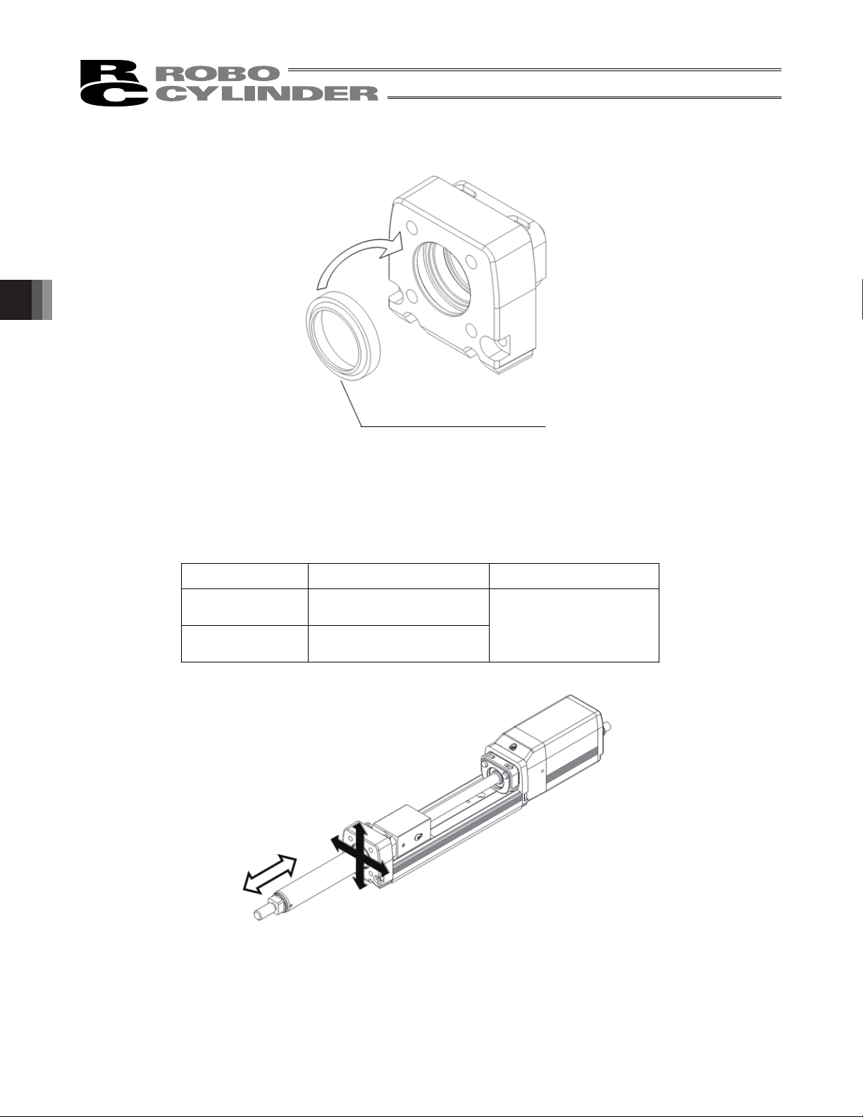
3) Detach the scraper.
Attach the scraper for replacement. Pay attention to the orientation of the scraper.
4) Affix the front housing temporarily. To tune the center of the front housing, pull out the rod as much as
5. Maintenance Inspection
possible and tighten the screws to hold the front housing.
Check if any abnormal resistance to the rod move. If there is, redo the center tuning process.
Scraper, projection in front
Screws to Hold Front Housing
Model Name Screw Diameter × Length Tightening Torque
RA5C
RA5R
RA6C
RA6R
5) Apply the grease to the rod sliding surfaces (inside of main body).
[Refer to 5.6 Grease Supply]
6) Attach the frame cover and put the actuator back to the original condition.
M4×20
2.07 N䱏m(0.21 kgf䱏 m)
M4×25
66
Page 73

6. External Dimensions
6.1 RA5C
Datum Surface
φ
8
4.5
5
(Attachment hole and datum surface)
58
52
3
4-M6 depth 12
φ
39
29.5
X
0
+0.012
4
Detail Diagram Y
φ
Detail: X
14
50
52
5
Scale 2 : 1
4.5
22
φ
31.5
22
O.D. Rod
M10×1.25
Stroke
41.5
33
MESESEME
D-M4 depth 12
2- φ 4H7 depth 5.5
(from bottom of base)
7.5
L
K
Oblong hole depth 5.5
(from bottom of base)
26
Y
18
N
J (Reamed hole and slotted hole)
B×100PM
C×100P
A
G
18.5
35
105(145)
29.5
Grounding Tap, M3, depth 6
21.5
(Same on opposite side)
F-φ4.5, Through
φ8 Counterbore, depth 4.5 (from other side)
24
113.5(153.5)
20
* Dimensions in bracket are for brake-equipped type
(300)
Affixing Cable
Allowable Bending = R50
2.5 2.547
M10×1.25
6
17
Rod Tip Equipped Nut
L Mass [kg]
Stroke
w/o
Brake
With
Brake
A B C D F G J K M N
w/o
Brake
50 300 340 73.5 0 0 4 4 127 18.5 153.5 73.5 35 1.9 2.1
100 350 390 123.5 0 0 4 4 177 68.5 203.5 123.5 85 2.1 2.4
150 400 440 173.5 1 0 6 4 227 118.5 253.5 73.5 135 2.4 2.6
200 450 490 223.5 1 1 6 6 277 168.5 303.5 123.5 85 2.7 2.9
250 500 540 273.5 2 1 8 6 327 218.5 353.5 73.5 135 2.9 3.1
300 550 590 323.5 2 2 8 8 377 268.5 403.5 123.5 85 3.2 3.4
350 600 640 373.5 3 2 10 8 427 318.5 453.5 73.5 135 3.4 3.7
400 650 690 423.5 3 3 10 10 477 368.5 503.5 123.5 85 3.7 3.9
(13)
(27)
6. External Dimensions
(19.6)
With
Brake
67
Page 74

6.2 RA6C
Datum Surface
φ
8
5
φ
4.5
(Attachment hole and datum surface)
Detail: X
4-M8 depth 16
φ
43
76
19
58
33
X
0
+0.012
4
Detail Diagram Y
Scale 2 : 1
6. External Dimensions
Stroke
Brake
50 368.5 418.5 76 0 0 4 6 146 91 181.5 76 30 3.4 3.9
100 418.5 468.5 126 0 0 4 6 196 141 231.5 126 80 3.7 4.2
150 468.5 518.5 176 1 0 6 6 246 191 281.5 76 130 4.1 4.6
200 518.5 568.5 226 1 1 6 8 296 241 331.5 126 80 4.4 4.9
250 568.5 618.5 276 2 1 8 8 346 291 381.5 76 130 4.7 5.2
300 618.5 668.5 326 2 2 8 10 396 341 431.5 126 80 5.0 5.5
350 668.5 718.5 376 3 2 10 10 446 391 481.5 76 130 5.4 5.9
400 718.5 768.5 426 3 3 10 12 496 441 531.5 126 80 5.7 6.2
450 768.5 818.5 476 4 3 12 12 546 491 581.5 76 130 6.0 6.5
500 818.5 868.5 526 4 4 12 14 596 541 631.5 126 80 6.3 6.8
25
φ
4.5
5
3 3
ME MESE SE
19
56
61
5
30.5
O.D. Rod
M14×1.5
Stroke
2- φ4H7 depth 5.5
(from bottom of base)
Oblong hole depth 5.5
(from bottom of base)
42
Width across Flats Section
9.5
D-M5 depth 9
Y
M
31
76
N
J (Reamed hole and slotted hole)
A
G25
L
B×100P
C×100P
133(183)K54
21
Grounding Tap, M3, depth 6
32
(Same on opposite side)
F-φ4.5, Through
φ8 Counterbore, depth 4.5 (from other side)
20
35
143.5(193.5)
20
* Dimensions in bracket are for brake-equipped type
L Mass [kg]
w/o
With
A B C D F G J K M N
Brake
(300)
Affixing Cable
Allowable Bending = R50
M14×1.5
Rod Tip Equipped Nut
Brake
w/o
228
With
Brake
(13)
(27)
25.4
68
Page 75

6.3 RA5R
M10×1.25
φ22
O.D. Rod
31.5
22 7.5
P.C.D.
53
52
39
14
29.5
X
4-M6 depth 12
90° Distribution
45°
14
50
52
(13)
Stroke
41.5 L
33
MEME SE SE
6 47
D-M4 depth 7
φ 4H7 depth 5.5
(from bottom of base)
(28)
Oblong hole depth 5.5
(from bottom of base)
26
Y
Affixing Cable
Allowable Bending
= R50
(28.5)
20(300)
K
F-φ4.5, Through
φ8 Counterbore, depth 4.5 (from other side)
J (Reamed hole and slotted hole)
A 35
B× 100 PM
G 3618
(156)
116
C× 100 PN
(32.5)
18.5
Grounding Tap, M3, depth 6
(Same on opposite side)
27.5
24
Mass [kg]
Stroke
L A B C D F G J K M N
w/o
Brake
50 181 73.5 0 0 4 4 127 18.5 153.5 73.5 35 1.9 2.1
100 231 123.5 0 0 4 4 177 68.5 203.5 123.5 85 2.1 2.4
150 281 173.5 1 0 6 4 227 118.5 253.5 73.5 135 2.4 2.6
200 331 223.5 1 1 6 6 277 168.5 303.5 123.5 85 2.7 2.9
250 381 273.5 2 1 8 6 327 218.5 353.5 73.5 135 2.9 3.1
300 431 323.5 2 2 8 8 377 268.5 403.5 123.5 85 3.2 3.4
350 481 373.5 3 2 10 8 427 318.5 453.5 73.5 135 3.4 3.7
400 531 423.5 3 3 10 10 477 368.5 503.5 123.5 85 3.7 3.9
With
Brake
4-M5 depth 15
37
29.5
37
6. External Dimensions
69
Page 76

6.4 RA6R
4-M8 depth 16
90° Distribution
P.C.D.43
45°
25
φ
O.D. Rod
M14×1.5
Stroke
3 3
SE
ME SE
42
9.5 (Area of paired faces)
30.5
(13)
54
ME
(28)
Affixing Cable
Allowable Bending
= R50
(300)
(55)
20
148.5(198.5)
L
K 33
(37)
Grounding Tap, M3, depth 6
(Same on opposite side)
4-M6 depth 14
19
58
63.5
33
19
X
56
60
6. External Dimensions
Stroke
50 214.5 76 0 0 4 6 146 91 181.5 76 30 3.4 3.9
100 264.5 126 0 0 4 6 196 141 231.5 126 80 3.7 4.2
150 314.5 176 1 0 6 6 246 191 281.5 76 130 4.1 4.6
200 364.5 226 1 1 6 8 296 241 331.5 126 80 4.4 4.9
250 414.5 276 2 1 8 8 346 291 381.5 76 130 4.7 5.2
300 464.5 326 2 2 8 10 396 341 431.5 126 80 5.0 5.5
350 514.5 376 3 2 10 10 446 391 481.5 76 130 5.4 5.9
400 564.5 426 3 3 10 12 496 441 531.5 126 80 5.7 6.2
450 614.5 476 4 3 12 12 546 491 581.5 76 130 6.0 6.5
500 664.5 526 4 4 12 14 596 541 631.5 126 80 6.3 6.8
150
(14)
75.25
2.5 61
2-φ 4H7 depth 5.5
(from bottom of base)
Y
Oblong hole depth 5.5
(from bottom of base)
D-M5 depth 9
31
B× 100 PM
A
25 43.5
J (Reamed hole and slotted hole)
G
L A B C D F G J K M N
F-φ4.5, Through
φ8 Counterbore, depth 4.5 (from other side)
C× 100 PN76
20
35
w/o
Brake
Mass [kg]
With
Brake
48
33
48
70
Page 77

7. Life
The product life is estimated as 5000km (reference) under the condition that it is operated with maximum
transportable weight, maximum acceleration and deceleration.
7. Life
71
Page 78

8. Warranty
8. Warranty
8.1 Warranty Period
One of the following periods, whichever is shorter:
y 18 months after shipment from our company
y 12 months after delivery to the specified location
y 2,500 hours of operation
8.2 Scope of the Warranty
Our products are covered by warranty when all of the following conditions are met. Faulty products covered by
warranty will be replaced or repaired free of charge:
(1) The breakdown or problem in question pertains to our product as delivered by us or our authorized dealer.
(2) The breakdown or problem in question occurred during the warranty period.
(3) The breakdown or problem in question occurred while the product was in use for an appropriate purpose
under the conditions and environment of use specified in the Operation Manual and catalog.
(4) The breakdown or problem in question was caused by a specification defect or problem, or by the poor
quality of our product.
Note that breakdowns due to any of the following reasons are excluded from the scope of warranty:
[1] Anything other than our product
[2] Modification or repair performed by a party other than us (unless we have approved such modification or
repair)
[3] Anything that could not be easily predicted with the level of science and technology available at the time
of shipment from our company
[4] A natural disaster, man–made disaster, incident or accident for which we are not liable
[5] Natural fading of paint or other symptoms of aging
[6] Wear, depletion or other expected result of use
[7] Operation noise, vibration or other subjective sensation not affecting function or maintenance
Note that the warranty only covers our product as delivered and that any secondary loss arising from a
breakdown of our product is excluded from the scope of warranty.
8.3 Honoring the Warranty
As a rule, the product must be brought to us for repair under warranty.
8.4 Limited Liability
(1) We shall assume no liability for any special damage, consequential loss or passive loss such as a loss of
expected profit arising from or in connection with our product.
(2) We shall not be liable for any program or control method created by the customer to operate our product or
for the result of such program or control method.
72
Page 79

8.5 Conditions of Conformance with Applicable Standards/Regulations, Etc., and Applications
(1) If our product is combined with another product or any system, device, etc., used by the customer, the
customer must first check the applicable standards, regulations and/or rules. The customer is also
responsible for confirming that such combination with our product conforms to the applicable standards, etc.
In such a case we will not be liable for the conformance of our product with the applicable standards, etc.
(2) Our product is for general industrial use. It is not intended or designed for the applications specified below,
which require a high level of safety. Accordingly, as a rule our product cannot be used in these applications.
Contact us if you must use our product for any of these applications:
[1] Medical equipment pertaining to maintenance or management of human life or health
[2] A mechanism or mechanical equipment intended to move or transport people (such as a vehicle,
railway facility or aviation facility)
[3] Important safety parts of mechanical equipment (such as safety devices)
[4] Equipment used to handle cultural assets, art or other irreplaceable items
(3) Contact us at the earliest opportunity if our product is to be used in any condition or environment that differs
from what is specified in the catalog or Operation Manual.
8.6 Other Items Excluded from Warranty
The price of the product delivered to you does not include expenses associated with programming, the dispatch
of engineers, etc. Accordingly, a separate fee will be charged in the following cases even during the warranty
period:
[1] Guidance for installation/adjustment and witnessing of test operation
[2] Maintenance and inspection
[3] Technical guidance and education on operating/wiring methods, etc.
[4] Technical guidance and education on programming and other items related to programs
8. Warranty
73
Page 80

Change History
Revision Date Description of Revision
September 2011
November 2011
February 2012
March 2012
Change History
May 2012
First edition
Second edition
Pg. 32 Caution note added regarding cable
Third edition
Pg. 11 Graph added for stroke and maximum speed limits when high–output
setting is ineffective
Pg. 17 to 18 Graph added for maximum acceleration and transportable weight
when high–output setting is ineffective
Pg. 54, 55 Mass added
Fourth edition
Pg. 7 Caution note added saying “Do not crash the rod to an obstacle with
high speed”
Pg. 28 Note added to tell platform should have a structure with enough
stiffness
Pg. 28, 30, 31, 32
Note changed to 1.8 times more of the nominal diameter for the length
of thread engagement on aluminum
Fifth edition
Pg. 1 to 7 Contents added and changed in Safety Guide
Pg. 23 Change Rod Non–Rotation Accuracy
(r0.1°ĺ0°)
August 2012
74
July 2012
Sixth edition
Pg. 23 Description was added regarding the conditions of the Rod
Non–Rotation Accuracy.
Seventh edition
Revised overall
Contents added in Motor reversing type
Page 81

Page 82

Manual No.: ME3718-7A (August 2012)
Head Office: 577-1 Obane Shimizu-KU Shizuoka City Shizuoka 424-0103, Japan
TEL +81-54-364-5105 FAX +81-54-364-2589
website: www.iai-robot.co.jp/
Technical Support available in USA, Europe and China
Head Office: 2690 W. 237th Street, Torrance, CA 90505
TEL (310) 891-6015 FAX (310) 891-0815
Chicago Office: 1261 Hamilton Parkway, Itasca, IL 60143
TEL (630) 467-9900 FAX (630) 467-9912
Atlanta Office: 1220 Kennestone Circle, Suite 108, Marietta, GA 30066
TEL (678) 354-9470 FAX (678) 354-9471
website: www.intelligentactuator.com
Ober der Röth 4, D-65824 Schwalbach am Taunus, Germany
TEL 06196-88950 FAX 06196-889524
SHANGHAI JIAHUA BUSINESS CENTER A8-303, 808, Hongqiao Rd. Shanghai 200030, China
TEL 021-6448-4753 FAX 021-6448-3992
website: www.iai-robot.com
The information contained in this document is subject to change without notice for purposes of
product improvement.
Copyright © 2012. Aug. IAI Corporation. All rights reserved.
12.08.000
 Loading...