

Page 1

ROBO Cylinder
RCP3 Actuator
Rod Type
Operating Manual
Fourth Edition
Motor coupling types
Motor reversing types
[Slim Small ROBO Cylinders] RA2AC/RA2BC
[Slim Small ROBO Cylinders] RA2AR/RA2BR
IAI America, Inc.
Page 2

Page 3

Please Read Before Use
Thank you for purchasing our product.
This Operation Manual explains the handling methods, structure and maintenance of this product, among
others, providing the information you need to know to use the product safely.
Before using the product, be sure to read this manual and fully understand the contents explained herein
to ensure safe use of the product.
The CD or DVD that comes with the product contains operation manuals for IAI products.
When using the product, refer to the necessary portions of the applicable operation manual by printing
them out or displaying them on a PC.
After reading the Operation Manual, keep it in a convenient place so that whoever is handling this product
can reference it quickly when necessary.
[Important]
• This Operation Manual is original.
• The product cannot be operated in any way unless expressly specified in this Operation Manual. IAI
shall assume no responsibility for the outcome of any operation not specified herein.
• Information contained in this Operation Manual is subject to change without notice for the purpose of
product improvement.
• If you have any question or comment regarding the content of this manual, please contact the IAI
sales office near you.
• Using or copying all or part of this Operation Manual without permission is prohibited.
• The company names, names of products and trademarks of each company shown in the sentences
are registered trademarks.
Page 4

CE Marking
If a compliance with the CE Marking is required, please follow Overseas Standards Compliance Manual
(ME0287) that is provided separately.
Page 5

Table of Contents
Safety Guide.................................................................................................................................. 1
Handling Precautions .................................................................................................................... 8
1. Part Names .......................................................................................................................... 12
2. External Drawings ................................................................................................................ 13
2.1 RCP3-RA2AC (Lead Screw, Ball Screw) .................................................................... 13
2.2 RCP3-RA2BC (Lead Screw, Ball Screw) .................................................................... 14
2.3 RCP3-RA2AR, Reversing to Right (Lead Screw, Ball Screw) .................................... 15
2.4 RCP3-RA2BR, Reversing to Right (Lead Screw, Ball Screw) .................................... 16
3. Cable Drawings .................................................................................................................... 17
3.1 PMEC, PSEP Controller Cables ................................................................................. 17
3.2 PCON Controller Cable............................................................................................... 18
4. Options ................................................................................................................................. 19
4.1 Brake Type.................................................................................................................. 19
4.2 Motor Reversing to Left, Motor Reversing to Right ..................................................... 19
5. Checking after Unpacking .................................................................................................... 20
5.1 Included Items............................................................................................................. 20
5.2 Operation Manuals Relating to This Product .............................................................. 20
5.3 How to Read Model Nameplate .................................................................................. 20
5.4 How to Read Model Number....................................................................................... 21
6. Specifications ....................................................................................................................... 22
7. Operation.............................................................................................................................. 24
7.1 Operational Conditions for Positioning Operation ...................................................... 24
7.2 Operational Conditions for Pressing Operation .......................................................... 28
7.2.1 RA2AC, RA2AR, RA2BC, RA2BR (Lead Screw) .......................................................28
7.2.2 RA2AC, RA2AR, RA2BC, RA2BR (Ball Screw) .........................................................29
8. Installation Environment and Storage Environment ............................................................. 30
8.1 Installation Environment.............................................................................................. 30
8.2 Storage/Preservation Environment ............................................................................. 30
9. Installation ............................................................................................................................ 31
9.1 Installation of Actuator................................................................................................. 31
9.2 Installation Surface...................................................................................................... 32
10. Connection with Controller ...................................................................................................33
11. Notes on Operation .............................................................................................................. 37
11.1 Loads Received by the Actuator ................................................................................. 37
11.1.1 Loads applied to RA2AC, RA2AR, RA2BC and RA2BR actuators ............................ 37
11.1.2 External force in thrust directions................................................................................ 37
Page 6

12. Life........................................................................................................................................ 38
12.1 Life of Actuator Using Ball Screws .............................................................................. 38
12.2 Life of Actuator Using Slide-screws ............................................................................ 38
12.2.1 Relationship of Cycle Time and Product Life.............................................................. 38
13. Maintenance and Inspection ................................................................................................ 40
13.1 Inspection Items and Schedule................................................................................... 40
13.2 Visual Inspection of Exterior........................................................................................ 40
13.3 Cleaning...................................................................................................................... 40
13.4 Inspection of Interior.................................................................................................... 41
13.5 Internal Cleaning ......................................................................................................... 41
13.6 Greasing...................................................................................................................... 42
13.6.1 Applicable Grease....................................................................................................... 42
13.6.2 How to Apply Grease .................................................................................................. 43
13.7 Belt
..............................................................................................................................
13.7.1 Inspection of Belt.........................................................................................................44
13.7.2 Applicable Belt ............................................................................................................ 44
13.7.3 Adjustment of Belt Tension.......................................................................................... 44
44
13.8 Motor Replacement (Pulse Motor: RCP3)................................................................... 45
13.9 Replacement of Belt and Motor for Reversing Type (Pulse Motor: RCP3) ................. 47
14. Warranty............................................................................................................................... 50
14.1 Warranty Period...........................................................................................................
50
14.2 Scope of Warranty....................................................................................................... 50
14.3 Honoring Warranty.......................................................................................................50
14.4 Limited Liability............................................................................................................50
14.5 Conditions of Conformance with Applicable Standards/Regulations, Etc.,
and Applications..........................................................................................................
51
14.6 Other Items Excluded from Warranty...........................................................................51
Change History............................................................................................................................ 52
Page 7

Safety Guide
“Safety Guide” has been written to use the machine safely and so prevent personal injury or property
damage beforehand. Make sure to read it before the operation of this product.
Safety Precautions for Our Products
The common safety precautions for the use of any of our robots in each operation.
No.
1 Model
Operation
Description
Selection
Description
This product has not been planned and designed for the application where
high level of safety is required, so the guarantee of the protection of
human life is impossible. Accordingly, do not use it in any of the following
applications.
1) Medical equipment used to maintain, control or otherwise affect human
life or physical health.
2) Mechanisms and machinery designed for the purpose of moving or
transporting people (For vehicle, railway facility or air navigation facility)
3) Important safety parts of machinery (Safety device, etc.)
Do not use the product outside the specifications. Failure to do so may
considerably shorten the life of the product.
Do not use it in any of the following environments.
1) Location where there is any inflammable gas, inflammable object or
explosive
2) Place with potential exposure to radiation
3) Location with the ambient temperature or relative humidity exceeding
the specification range
4) Location where radiant heat is added from direct sunlight or other large
heat source
5) Location where condensation occurs due to abrupt temperature
changes
6) Location where there is any corrosive gas (sulfuric acid or hydrochloric
acid)
7) Location exposed to significant amount of dust, salt or iron powder
8) Location subject to direct vibration or impact
For an actuator used in vertical orientation, select a model which is
equipped with a brake. If selecting a model with no brake, the moving part
may drop when the power is turned OFF and may cause an accident such
as an injury or damage on the work piece.
1
Page 8

No.
Operation
Description
Description
2 Transportation When carrying a heavy object, do the work with two or more persons or
utilize equipment such as crane.
When the work is carried out with 2 or more persons, make it clear who is
to be the leader and who to be the follower(s) and communicate well with
each other to ensure the safety of the workers.
When in transportation, consider well about the positions to hold, weight
and weight balance and pay special attention to the carried object so it
would not get hit or dropped.
Transport it using an appropriate transportation measure.
The actuators available for transportation with a crane have eyebolts
attached or there are tapped holes to attach bolts. Follow the instructions
in the operation manual for each model.
Do not step or sit on the package.
Do not put any heavy thing that can deform the package, on it.
When using a crane capable of 1t or more of weight, have an operator
who has qualifications for crane operation and sling work.
When using a crane or equivalent equipments, make sure not to hang a
load that weighs more than the equipment’s capability limit.
Use a hook that is suitable for the load. Consider the safety factor of the
hook in such factors as shear strength.
Do not get on the load that is hung on a crane.
Do not leave a load hung up with a crane.
Do not stand under the load that is hung up with a crane.
3 Storage and
Preservation
The storage and preservation environment conforms to the installation
environment. However, especially give consideration to the prevention of
condensation.
Store the products with a consideration not to fall them over or drop due to
an act of God such as earthquake.
4 Installation
and Start
(1) Installation of Robot Main Body and Controller, etc.
Make sure to securely hold and fix the product (including the work part). A
fall, drop or abnormal motion of the product may cause a damage or injury.
Also, be equipped for a fall-over or drop due to an act of God such as
earthquake.
Do not get on or put anything on the product. Failure to do so may cause
an accidental fall, injury or damage to the product due to a drop of
anything, malfunction of the product, performance degradation, or
shortening of its life.
When using the product in any of the places specified below, provide a
sufficient shield.
1) Location where electric noise is generated
2) Location where high electrical or magnetic field is present
3) Location with the mains or power lines passing nearby
4) Location where the product may come in contact with water, oil or
chemical droplets
2
Page 9

No.
Operation
Description
4 Installation
and Start
Description
(2) Cable Wiring
Use our company’s genuine cables for connecting between the actuator
and controller, and for the teaching tool.
Do not scratch on the cable. Do not bend it forcibly. Do not pull it. Do not
coil it around. Do not insert it. Do not put any heavy thing on it. Failure to
do so may cause a fire, electric shock or malfunction due to leakage or
continuity error.
Perform the wiring for the product, after turning OFF the power to the unit,
so that there is no wiring error.
When the direct current power (+24V) is connected, take the great care of
the directions of positive and negative poles. If the connection direction is
not correct, it might cause a fire, product breakdown or malfunction.
Connect the cable connector securely so that there is no disconnection or
looseness. Failure to do so may cause a fire, electric shock or malfunction
of the product.
Never cut and/or reconnect the cables supplied with the product for the
purpose of extending or shortening the cable length. Failure to do so may
cause the product to malfunction or cause fire.
(3) Grounding
The grounding operation should be performed to prevent an electric shock
or electrostatic charge, enhance the noise-resistance ability and control
the unnecessary electromagnetic radiation.
For the ground terminal on the AC power cable of the controller and the
grounding plate in the control panel, make sure to use a twisted pair cable
with wire thickness 0.5mm
2
(AWG20 or equivalent) or more for grounding
work. For security grounding, it is necessary to select an appropriate wire
thickness suitable for the load. Perform wiring that satisfies the
specifications (electrical equipment technical standards).
Perform Class D Grounding (former Class 3 Grounding with ground
resistance 100 or below).
3
Page 10

No.
4 Installation
Operation
Description
and Start
Description
(4) Safety Measures
When the work is carried out with 2 or more persons, make it clear who is
to be the leader and who to be the follower(s) and communicate well with
each other to ensure the safety of the workers.
When the product is under operation or in the ready mode, take the safety
measures (such as the installation of safety and protection fence) so that
nobody can enter the area within the robot’s movable range. When the
robot under operation is touched, it may result in death or serious injury.
Make sure to install the emergency stop circuit so that the unit can be
stopped immediately in an emergency during the unit operation.
Take the safety measure not to start up the unit only with the power turning
ON. Failure to do so may start up the machine suddenly and cause an
injury or damage to the product.
Take the safety measure not to start up the machine only with the
emergency stop cancellation or recovery after the power failure. Failure to
do so may result in an electric shock or injury due to unexpected power
input.
When the installation or adjustment operation is to be performed, give
clear warnings such as “Under Operation; Do not turn ON the power!” etc.
Sudden power input may cause an electric shock or injury.
Take the measure so that the work part is not dropped in power failure or
emergency stop.
Wear protection gloves, goggle or safety shoes, as necessary, to secure
safety.
Do not insert a finger or object in the openings in the product. Failure to do
so may cause an injury, electric shock, damage to the product or fire.
When releasing the brake on a vertically oriented actuator, exercise
precaution not to pinch your hand or damage the work parts with the
actuator dropped by gravity.
5 Teaching When the work is carried out with 2 or more persons, make it clear who is
to be the leader and who to be the follower(s) and communicate well with
each other to ensure the safety of the workers.
Perform the teaching operation from outside the safety protection fence, if
possible. In the case that the operation is to be performed unavoidably
inside the safety protection fence, prepare the “Stipulations for the
Operation” and make sure that all the workers acknowledge and
understand them well.
When the operation is to be performed inside the safety protection fence,
the worker should have an emergency stop switch at hand with him so that
the unit can be stopped any time in an emergency.
When the operation is to be performed inside the safety protection fence,
in addition to the workers, arrange a watchman so that the machine can
be stopped any time in an emergency. Also, keep watch on the operation
so that any third person can not operate the switches carelessly.
Place a sign “Under Operation” at the position easy to see.
When releasing the brake on a vertically oriented actuator, exercise
precaution not to pinch your hand or damage the work parts with the
actuator dropped by gravity.
* Safety protection Fence : In the case that there is no safety protection
fence, the movable range should be indicated.
4
Page 11

No.
Operation
Description
Description
6 Trial Operation When the work is carried out with 2 or more persons, make it clear who is
to be the leader and who to be the follower(s) and communicate well with
each other to ensure the safety of the workers.
After the teaching or programming operation, perform the check operation
one step by one step and then shift to the automatic operation.
When the check operation is to be performed inside the safety protection
fence, perform the check operation using the previously specified work
procedure like the teaching operation.
Make sure to perform the programmed operation check at the safety
speed. Failure to do so may result in an accident due to unexpected
motion caused by a program error, etc.
Do not touch the terminal block or any of the various setting switches in
the power ON mode. Failure to do so may result in an electric shock or
malfunction.
7 Automatic
Operation
Check before starting the automatic operation or rebooting after operation
stop that there is nobody in the safety protection fence.
Before starting automatic operation, make sure that all peripheral
equipment is in an automatic-operation-ready state and there is no alarm
indication.
Make sure to operate automatic operation start from outside of the safety
protection fence.
In the case that there is any abnormal heating, smoke, offensive smell, or
abnormal noise in the product, immediately stop the machine and turn
OFF the power switch. Failure to do so may result in a fire or damage to
the product.
When a power failure occurs, turn OFF the power switch. Failure to do so
may cause an injury or damage to the product, due to a sudden motion of
the product in the recovery operation from the power failure.
5
Page 12

No.
8 Maintenance
Operation
Description
and Inspection
Description
When the work is carried out with 2 or more persons, make it clear who is
to be the leader and who to be the follower(s) and communicate well with
each other to ensure the safety of the workers.
Perform the work out of the safety protection fence, if possible. In the case
that the operation is to be performed unavoidably inside the safety
protection fence, prepare the “Stipulations for the Operation” and make
sure that all the workers acknowledge and understand them well.
When the work is to be performed inside the safety protection fence,
basically turn OFF the power switch.
When the operation is to be performed inside the safety protection fence,
the worker should have an emergency stop switch at hand with him so that
the unit can be stopped any time in an emergency.
When the operation is to be performed inside the safety protection fence,
in addition to the workers, arrange a watchman so that the machine can
be stopped any time in an emergency. Also, keep watch on the operation
so that any third person can not operate the switches carelessly.
Place a sign “Under Operation” at the position easy to see.
For the grease for the guide or ball screw, use appropriate grease
according to the Operation Manual for each model.
Do not perform the dielectric strength test. Failure to do so may result in a
damage to the product.
When releasing the brake on a vertically oriented actuator, exercise
precaution not to pinch your hand or damage the work parts with the
actuator dropped by gravity.
The slider or rod may get misaligned OFF the stop position if the servo is
turned OFF. Be careful not to get injured or damaged due to an
unnecessary operation.
Pay attention not to lose the cover or untightened screws, and make sure
to put the product back to the original condition after maintenance and
inspection works.
Use in incomplete condition may cause damage to the product or an injury.
* Safety protection Fence : In the case that there is no safety protection
fence, the movable range should be indicated.
9 Modification
and Dismantle
Do not modify, disassemble, assemble or use of maintenance parts not
specified based at your own discretion.
10 Disposal When the product becomes no longer usable or necessary, dispose of it
properly as an industrial waste.
When removing the actuator for disposal, pay attention to drop of
components when detaching screws.
Do not put the product in a fire when disposing of it.
The product may burst or generate toxic gases.
11 Other Do not come close to the product or the harnesses if you are a person
who requires a support of medical devices such as a pacemaker. Doing so
may affect the performance of your medical device.
See Overseas Specifications Compliance Manual to check whether
complies if necessary.
For the handling of actuators and controllers, follow the dedicated
operation manual of each unit to ensure the safety.
6
Page 13
Alert Indication
The safety precautions are divided into “Danger”, “Warning”, “Caution” and “Notice” according to the
warning level, as follows, and described in the Operation Manual for each model.
Level Degree of Danger and Damage Symbol
Danger
Warning
Caution
Notice
This indicates an imminently hazardous situation which, if the
product is not handled correctly, will result in death or serious injury.
This indicates a potentially hazardous situation which, if the product
is not handled correctly, could result in death or serious injury.
This indicates a potentially hazardous situation which, if the product
is not handled correctly, may result in minor injury or property
damage.
This indicates lower possibility for the injury, but should be kept to
use this product properly.
Danger
Warning
Caution
Notice
7
Page 14

Handling Precautions
1. Do Not Set Speed and Acceleration/Deceleration Higher Than the Rated Values.
Do not set speed and acceleration/deceleration higher than the rated values. It causes vibration, failure, or
shortening of life. If acceleration/deceleration higher than the rated value is set, creeping phenomenon or
coupling slide may occur.
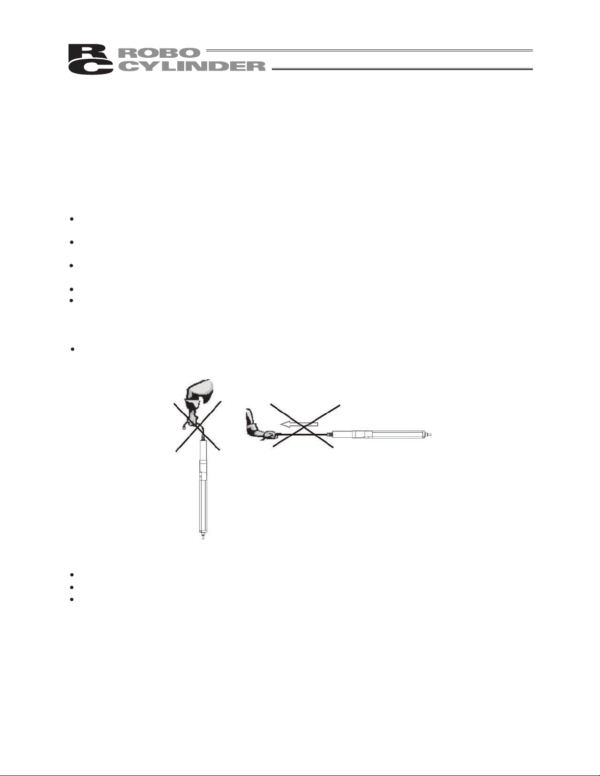
2. Do Not Apply External Force on the Rod from Directions Other Than the Rod
Traveling Direction.
Do not apply external force (radial load) on the rod from directions other than the rod traveling direction. If
force in the perpendicular or rotating direction is applied on the rod, the actuator may be damaged or
malfunction.
If external force from directions other than the traveling direction is applied, mount external guide or similar.
3. Oil Film of Grease May Run Out If Short-distance Reciprocating Operation is Performed.
When performing continuous reciprocating operation of a distance of 30 mm or shorter, oil film of grease
may run out. To recover oil film, perform approximately five cycles of a distance of 50 mm or longer, every
5,000 to 10,000 cycles, as a guideline
Make sure to attach the Horizontal Articulated Robot properly by following this
4.
operation manual.
Using the product with the Horizontal Articulated Robot not being certainly retained or affixed may cause
abnormal noise, vibration, malfunction or shorten the product life.
8
Page 15
5. Transportation
5.1 Handling a Single Actuator
Please adhere to the following when handling a single actuator.
5.1.1 Handling the Packed Unit
Unless otherwise specified, the actuator is shipped with each axis packaged separately.
Do not damage or drop. The package is not applied with any special treatment that enables it to
resist an impact caused by a drop or crash.
Transport a heavy package with at least more than two operators. Consider an appropriate
method for transportation.
Keep the unit in horizontal orientation when placing it on the ground or transporting. Follow the
instruction if there is any for the packaging condition.
Do not step or sit on the package.
Do not put any load that may cause a deformation or breakage of the package.
5.1.2 Handling the Actuator After Unpacking
Do not carry an actuator by a cable or attempt to move it by pulling the cable.
Hold the body base when transporting the actuator.
Be careful not to bump the actuator into anything when moving it.
Do not apply an excessive force to each part of the actuator. In particular, prevent the motor unit
and rear bracket from receiving an unnecessary force.
Supplement) For the names of each part of the actuator, refer to 1, "Part Names".
9
Page 16

5.2 Handling the Actuator Assembly
When carrying the actuator, exercise caution not to bump it against nearby objects or structures.
Secure the sliders to prevent sudden movement during transport.
If any end of the actuator is overhanging, secure it properly to avoid significant movement due to
external vibration.
When transporting the assembly without the ends of the actuators fastened, do not subject the
assembly to an impact of 0.3 G or more.
When suspending the mechanical equipment (system) with ropes, avoid applying force to actuator,
connector box, etc. Also, avoid the cables being pinched or caused an excessive deformation.
10
Page 17

11
Page 18
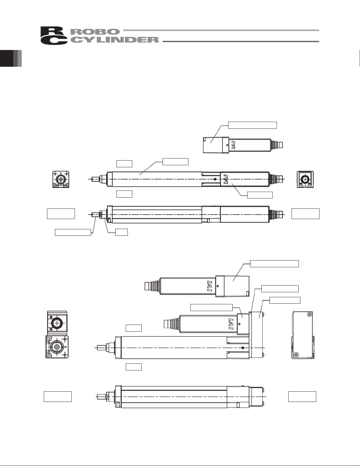
1. Part Names
The names of the actuator parts are indicated below.
In this manual, the right and left are determined by viewing the actuator from the top and from the motor
side.
1. Part Names
z “Motor coupling type” RA2AC/RA2BC(Lead screw, ball screw)
Motor unit with brake
Rod cover
Other side
Rod end bracket
Right
Left
Rod
* Refer to 2, “External Dimensions” for details.
z “Motor reversing type” RA2AR/RA2BR (Lead screw, ball screw)
Reversing bracket
Right
Motor unit
Motor side
Motor unit with brake
Reversing plate
Pulley cover
Left
Other side
* Refer to 2, “External Dimensions” for details.
12
Motor side
Page 19

13
2. External Drawings
2.1 RCP3-RA2AC (Lead Screw, ball Screw)
(without brake)
(73.5) 20P (20 square) motor
2. External Drawings
L (20SP (20 square))
A B C D Weight [kg]
With brake Without brake With brake
with
2-3H7 depth 3
D-M3 depth 5
(from base bottom surface)
L
L (20P (20 square))
brake
Without brake
brake
without
25 168 212 94.5 25 0 4 0.31
50 193 237 119.5 50 0 4 0.33
75 218 262 144.5 75 0 4 0.36
ST
For those with a brake, the
20SP (20 square) with motor brake 20SP (20 square) without brake 20P (20 square) with brake
3H7 depth 3
(from base
bottom surface)
2-M3 depth 4
Scale: 2:1
Detail view of Z
100 243 287 169.5 100 50 6 0.37
: Home
: Mechanical end
: Stroke end
weight increases by 0.1kg.
Page 20

2.2 RCP3-RA2BC (Lead Screw, Ball Screw)
2. External Drawings
(without brake)
(73.5) 20P (20 square) motor
2-3H7 depth 3
(from base bottom surface)
D-M3 depth 4
L (20SP (20 square))
A B C D Weight [kg]
With brake Without brake With brake
with
brake
L
L (20P (20 square))
Without brake
brake
without
25 168 212 94.5 25 0 4 0.36
50 193 237 119.5 50 0 4 0.39
75 218 262 144.5 75 0 4 0.42
ST
100 243 287 169.5 100 50 6 0.45
: Home
: Mechanical end
For those with a brake, the
weight increases by 0.1kg.
125 268 312 194.5 125 62.5 6 0.48
150 293 337 219.5 150 75 6 0.51
: Stroke end
20SP (20 square) with motor brake 20SP (20 square) without motor brake 20P (20 square) with motor brake
14
3h7 depth 3
(from base
bottom surface)
4-M3 depth 4
Scale: 2:1
Detail view of Z
Page 21

15
2. External Drawings
2.3 RCP3-RA2AR, Reversing to Right (Lead Screw, Ball Screw)
D-M3 depth 5
2-3H7 depth 3
(from base bottom surface)
25 111.5 94.5 25 0 4 0.34
ST L A B C D Weight [kg]
50 136.5 119.5 50 0 4 0.36
75 161.5 144.5 75 0 4 0.39
: Home
: Mechanical end
100 186.5 169.5 100 50 6 0.4
: Stroke end
20SP (20 square) with motor brake 20SP (20 square) without motor brake 20P (20 square) with motor brake
(88.5) 20P (20 square) motor (without brake)
3H7 depth 3
(from base
bottom surface)
2-M3 depth 4
Scale: 2:1
Detail view of Z
For those with a brake, the
weight increases by 0.1kg.
Page 22

2.4 RCP3-RA2BR, Reversing to Right (Lead Screw, Ball Screw)
2. External Drawings
25 111.5 94.5 25 0 4 0.38
50 136.5 119.5 50 0 4 0.41
75 161.5 144.5 75 0 4 0.44
ST L A B C D Weight [kg]
D-M3 depth 4
2-3H7 depth 3
(from base bottom surface)
100 186.5 169.5 100 50 6 0.47
125 211.5 194.5 125 62.5 6 0.5
: Home
: Mechanical end
150 236.5 219.5 150 75 6 0.53
: Stroke end
20SP (20 square) with motor brake 20SP (20 square) without motor brake 20P (20 square) with motor brake
(88.5) 20P (20 square) motor (without brake)
3H7 depth 3
(from base
bottom surface)
4-M3 depth 4
Scale: 2:1
Detail view of Z
For those with a brake, the
weight increases by 0.1kg.
16
Page 23

3. Cable Drawings
3.1 PMEC, PSEP Controller Cables
Integrated motor/encoder cable
(CB-APSEP-MPA***)
*** indicates the cable length (L). Up to 20 m can be specified.
Example) 080 = 8 m
3. Cable Drawings
[1][2]
[5] [3][4]
[6]
Model Nameplate
Lot number
No. Item Model number Manufacturer
1 Housing
2 Contact
3 Housing PADP-24V-1-S (white, 2.0-mm pitch, 24 poles)
4 Contact
5 Coupler cover TMS-4ZB008
6 ZUL2854-OHFRPCVVSW
D-1100D 1-1827863-1
(black, 2.0-mm pitch, 22 poles)
D-1 1827570-2 (AWG 22 to 18, 1.08 to 1.6 )
SPND-001T-C0.5 (AWG 26 to 22, 1.0 to 1.5 )
25AWG x 6P + 25AWG x 2C + 22AWG x 6C,
TS08V0350
Terminal number
on actuator side
[1] [3]
Wiring diagram
[PCON] (ACON)
Black
White
Brown
Green
Yellow
Red
Orange
Gray
White
Yellow
Red
Green
Black
Brown
Black
(identification tape)
Brown
(identification tape)
Green
(identification tape)
(identification tape)
White
(identification tape)
Yellow
(ID tape)
Red
Terminal number
on controller side
AMP
JST
TATSUTA ELECTRIC
WIRE & CABLE
TATSUTA ELECTRIC
WIRE & CABLE
Shield [FG] (FG)
17
Page 24

3.2 PCON Controller Cable
w
RCA3 Integrated motor/encoder cable
(CB-PCS-MPA***)
3. Cable Drawings
No. Item Model number Manufacturer
[1] Receptacle housing D-1100D 1-1827863-1 AMP
[2] Receptacle contact D-1 1827570-2 AMP
[3] Socket D2100D 1-1318119-3 Hirose
[4] Socket contact D-2 1318105-1 Hirose
[5] Housing PHDR-16VS JST
[6] Contact SPHD-001T-P0.5 JST
[7] UL2854-VVSWKA TS06V1200 (25AWG x 7P + 22AWG x 6C)
[1][2]
[7]
Model Nameplate
*** indicates the cable length (L). Up to 10 m can be specified.
Example) 080 = 8 m
[3][4]
[7]
[5][6]
TATSUTA ELECTRIC
WIRE & CABLE
Terminal number
on actuator side
[1]
Wiring diagram [Serial]
Black
White
Red
Green
Yello
Brawn
Pink (Red)
Pink (Blue)
White (Red)
White (Blue)
Orange (Red)
Orange (Blue)
Gray (Red)
Gray (Blue)
Orange (Blue/continuous)
Gray (Red/continuous)
Gray (Blue/continuous)
(Shield)
Terminal number
on controller side
[3]
[5]
18
Page 25

4. Options
4.1 Brake Type
The brake is a mechanism designed to prevent the slider from dropping on a vertically installed actuator
when the power or servo is turned off.
Use the brake to prevent the installed work part, etc., from being damaged due to the falling rod.
(Notes on installation)
With the RA2AC and RA2BC, the brake project from the bearing surface by 1 mm.
When using a base surface for installation, a measure to raise the unit using a foot bracket, etc. is
required.
Brake housing
Bearing surface on base
Brake housing
Bearing surface on base
4. Options
4.2 Motor Reversing to Left, Motor Reversing to Right
The motor reversing direction can be specified for the motor reversing types RA2AR and RA2BR.
“ML” indicates reversing to the left, while “MR” indicates reversing to the right, as viewed from the motor
side.
19
Page 26

5. Checking after Unpacking
r
After unpacking, check the product condition and the included items.
5.1 Included Items
No. Item Model number Remarks
1 Actuator
Accessories
RCP3 integrated motor/
2
encoder cable
3 First Step Guide
4 Operating Manual
5 Safety Guide
5.2 Operation Manuals Relating to This Product
Refer to “How to Read Model Nameplate” and
“How to Read Model Number.”
CB-APSEP-MPA: PSEP type
CB-PCS-MPA: PCON, PSEL type
5. Checking after Unpacking
No. Name Control No.
1 Operation Manual for PSEL Controller MJ0172
2 Operation Manual for PCON-C/CG/CF Controller MJ0170
3 Operation Manual for PCON-CY Controller MJ0156
4 Operation Manual for PCON-SE Controller MJ0163
5 Operation Manual for PCON-PL/PO Controller MJ0164
6 MEC Controller Operation Manual MJ0245
7 Operation Manual for ASEP/PSEP Controller MJ0216
8 PC Software IA-101-X-MW/IA-101-X-USBMW Operation Manual MJ0154
9 Operation Manual for PC Software RCM-101MW/RCM-101-USB MJ0155
10 MEC PC Software Operation Manual MJ0248
11 Teaching Pendant SEL-T/TD Operation Manual MJ0183
12 Operation Manual for Teaching Pendant CON-T/TG MJ0178
13 Touch Panel Teaching CON-PT/PD/PG Operation Manual MJ0227
14 Touch Panel Teaching SEP-PT Operation Manual MJ0217
15 Operation Manual for Simple Teaching Pendant RCM-E MJ0174
16 Operation Manual for Data Setter RCM-P MJ0175
17 Operation Manual for Touch Panel Display RCM-PM-01 MJ0182
5.3 How to Read Model Nameplate
Model
Serial numbe
20
Page 27

5.4 How to Read Model Number
<Series name>
<Type>
Motor coupling type
RA2AC
RA2BC
Motor reversing type
RA2AR
RA2BR
<Encoder type>
I: Incremental
<Motor type>
20P (20, square), 20SP (20, square)
RA2AC, RA2BC,
RA2AR, RA2BR
<Lead>
RA2AC, RA2AR,
1/2/4
1S/2S/4S
RA2BC, RA2BR
1/2/4/6
2S/4S/6S
<Option>
B: Brake type
ML: Motor reversing to left
(Motor reversing type only)
MR: Motor reversing to right
(Motor reversing type only)
5. Checking after Unpacking
<Cable length>
N: None
P: 1 m
S: 3 m
M: 5 m
X: Specified length
<Applicable controller>
P: PSEL
PCON-C/CG
PCON-CY
PCON-SE
PCON-PL/PO
P3: PMEC
PSEP
<Stroke>
21
Page 28

6. Specifications
Maximum loading
Positioning repeatability
Number of encoder pulses
*1 The maximum speed may not be reached depending on the stroke.
*2 The acceleration/deceleration is assumed to be 0.2 G in both horizontal and vertical applications.
6. Specifications
*3 The default value.
*4 The number of pulses input in the controller
Maximum loading
Positioning repeatability
Number of encoder pulses
Item
RA2AC (Lead screw)
RA2AR (Lead screw)
Lead mm 1 2 4
Maximum speed
(*1)
mm/sec 50 100 200
Stroke mm 25 to 100 (in 25 steps)
Maximum thrust N 36 18 9
Horizontal kg 1 0.5 0.25
Vertical kg 0.5 0.25 0.125
(*3)
(*3)
(*4)
mm
0.05
mm 0.3
Pulse 800
capacity
Lost motion
(*2)
RA2AC (Ball screw)
Item
RA2AR (Ball screw)
20P (20, square) motor 20SP (20, square) motor
Lead mm 1 2 4 1 2 4
Maximum speed
(*1)
mm/sec 50 100 200 50 100 200
Stroke mm 25 to 100 (in 25 steps) 25 to 150 (in 25 steps)
Maximum thrust N 72 36 18 132 66 33
Horizontal kg 2 1 0.5 4 2 1
Vertical kg 0.75 0.375 0.2 1.25 0.625 0.325
(*3)
(*3)
(*4)
mm
0.02 0.02
mm 0.1 0.1
Pulse 800 800
capacity
Lost motion
(*2)
*1 The maximum speed may not be reached depending on the stroke.
*2 The acceleration/deceleration is assumed to be 0.3 G in horizontal application and 0.2 G in vertical
application.
*3 The default value.
*4 The number of pulses input in the controller
22
Page 29

Item
RA2BC (Lead screw)
RA2BR (Lead screw)
Lead mm 2 4 6
Maximum speed
(*1)
mm/sec 100 200 300
Stroke mm 25 to 150 (in 25 steps)
Maximum thrust N 18 9 6
Maximum loading
capacity
(*2)
Positioning repeatability
Lost motion
Number of encoder pulses
Horizontal kg 1 0.5 0.25
Vertical kg 0.5 0.25 0.125
(*3)
(*3)
(*4)
mm
0.05
mm 0.3
Pulse 800
*1 The maximum speed may not be reached depending on the stroke.
*2 The acceleration/deceleration is assumed to be 0.2 G in both horizontal and vertical applications.
*3 The default value.
*4 The number of pulses input in the controller
RA2BC (Ball screw)
Item
RA2BR (Ball screw)
20P (20, square) motor 20SP (20, square) motor
Lead mm 1 2 4 6 1 2 4 6
Maximum speed
(*1)
mm/sec 50 100 200 300 50 100 200 300
Stroke mm 25 to 150 (in 25 steps) 25 to 100 (in 25 steps)
Maximum thrust N 72 36 18 9 132 66 33 22
Maximum loading
capacity
(*2)
Positioning repeatability
Lost motion
Number of encoder pulses
Horizontal kg 4 2 1 0.5 8 4 2 1
Vertical kg 1.5 0.75 0.375 0.2 2.5 1.25 0.625 0.325
(*3)
(*3)
(*4)
mm
0.02 0.02
mm 0.1 0.1
Pulse 800 800
6. Specifications
*1 The maximum speed may not be reached depending on the stroke.
*2 The acceleration/deceleration is assumed to be 0.3 G in horizontal application and 0.2 G in vertical
application.
*3 The default value.
*4 The number of pulses input in the controller
23
Page 30

7. Operation
7.1 Operational Conditions for Positioning Operation
By following the procedures below, check whether the operation is available.
[1] Operation
Check the operational conditions [1] to [5].
[1] Load installation orientation (horizontal, upright, vertical)
[2] Stroke L (mm)
[3] Maximum speed V (mm/s)
[4] Acceleration a (G)
[5] Loading capacity W (kg)
Installation orientation
7. Operation
Horizontal
Upright
Vertical
24
Page 31

[2] Stroke, maximum speed, acceleration
Check whether the operation is available by [2] stroke, [3] maximum speed and [4] acceleration.
Table 1
Installation
Orientation
Horizontal
Upright
Vertical
Horizontal
Upright
Model
RA2AC
RA2AR
(Lead screw)
RA2BC
RA2BR
(Lead screw)
RA2AC
RA2AR
(Ball screw)
RA2BC
RA2BR
(Ball screw)
Lead
(mm)
Acceleration
(G)
Max Speed
1 0.2 50
2 0.2 100
4 0.2 200
2 0.2 100
4 0.2 200
6 0.2 300
1 0.3 50
2 0.3 100
4 0.3 200
1 0.3 50
2 0.3 100
4 0.3 200
(mm/s)
Stroke
(mm)
25, 50, 75, 100
25, 50, 75, 100, 125, 150
25, 50, 75, 100
25, 50, 75, 100, 125, 150
6 0.3 300
RA2AC
RA2AR
(Ball screw)
Vertical
RA2BC
RA2BR
(Ball screw)
1 0.2 50
2 0.2 100
4 0.2 200
1 0.2 50
2 0.2 100
4 0.2 200
25, 50, 75, 100
25, 50, 75, 100, 125, 150
6 0.2 300
7. Operation
How to decide: [2] Desired stroke model stroke
[3] Desired speed
[4] Desired acceleration
maximum speed for selected stroke
0.2 G
[3] Maximum speed, loading mass
Check whether the operation is available by [3] maximum speed and [5] loading capacity.
Pulse motor (RCP3) (Graph 1)
How to decide: You can use any model that has a [3] maximum speed and [4] loading mass that exceeds
your usage range.
25
Page 32

Graphs 1 Pulse motor (RCP3)
Horizontal Vertical
7. Operation
(Lead
screw)
(Lead
screw)
Correlation diagram of speed vs. loading capacity (horizontal)
Lead 1
Lead 2
Lead 4
Loading capacity (kg)
Speed (mm/sec)
Correlation diagram of speed vs. loading capacity (horizontal)
Lead 2
Lead 4
Lead 6
Loading capacity (kg)
Speed (mm/sec)
Correlation diagram of speed vs. loading capacity (horizontal)
Correlation diagram of speed vs. loading capacity (vertical)
Lead 1
Lead 2
Lead 4
Loading capacity (kg)
Speed (mm/sec)
Correlation diagram of speed vs. loading capacity (vertical)
Lead 2
Lead 4
Lead 6
Loading capacity (kg)
Speed (mm/sec)
Correlation diagram of speed vs. loading capacity (vertical)
26
(Ball
screw)
motor
: 20P
(Ball
screw)
motor
: 20SP
Lead 1
Lead 2
Loading capacity (kg)
Lead 4
Speed (mm/sec)
Correlation diagram of speed vs. loading capacity (horizontal)
Lead 1
Lead 2
Lead 4
Loading capacity (kg)
Speed (mm/sec)
Lead 1
Lead 2
Lead 4
Loading capacity (kg)
Speed (mm/sec)
Correlation diagram of speed vs. loading capacity (vertical)
Lead 1
Lead 2
Lead 4
Loading capacity (kg)
Speed (mm/sec)
Page 33

Horizontal Vertical
(Ball
screw)
motor
: 20P
(Ball
screw)
motor
: 20SP
Correlation diagram of speed vs. loading capacity (horizontal)
Lead 1
Lead 2
Loading capacity (kg)
Lead 4
Lead 6
Speed (mm/sec)
Correlation diagram of speed vs. loading capacity (horizontal)
Lead 1
Lead 2
Lead 4
Loading capacity (kg)
Lead 6
Speed (mm/sec)
Correlation diagram of speed vs. loading capacity (vertical)
Lead 1
Lead 2
Loading capacity (kg)
Lead 4
Lead 6
Speed (mm/sec)
Correlation diagram of speed vs. loading capacity (vertical)
Lead 1
Lead 2
Lead 4
Loading capacity (kg)
Lead 6
Speed (mm/sec)
7. Operation
27
Page 34

7.2 Operational Conditions for Pressing Operation
r
7.2.1 RA2AC, RA2AR, RA2BC, RA2BR (Lead Screw)
[1] Operation
Check the operational condition of pressing force F (N).
* For push & hold operations, movement speed is set at 5 mm/s.
[2] Push force
Check whether the operation is available by pressing force.
(The graphs provide some margin by considering a drop in lead screw efficiency over time.)
How to decide: The operation is available as long as the pressing force is in the ranges shown in the graphs.
7. Operation
Push force (N)
Push force (N)
RA2AC/RA2AR push force
Lead 1
Current-limiting value (ratio %)
RA2AC/RA2AR push force
Lead 2
Current-limiting value (ratio %)
RA2AC/RA2AR push force
Lead 4
Push speed:
5 mm/s
Push speed:
5 mm/s
Push speed:
5 mm/s
Push force (N)
Push force (N)
RA2BC/RA2BR push fo
ce
Lead 2
Current-limiting value (ratio %)
RA2BC/RA2BR push force
Lead 4
Current-limiting value (ratio %)
RA2BC/RA2BR push force
Lead 6
Push speed:
5 mm/s
Push speed:
5 mm/s
Push speed:
5 mm/s
Push force (N)
Current-limiting value (ratio %)
Push force (N)
Current-limiting value (ratio %)
28
Page 35

7.2.2 RA2AC, RA2AR, RA2BC, RA2BR (Ball Screw)
[1] Operation
Check the operational condition of pressing force F (N).
* For push & hold operations, movement speed is set at 5 mm/s.
[2] Push force
Check whether the operation is available by pressing force.
How to decide: The operation is available as long as the pressing force is in the ranges shown in the graphs.
Push force (N)
Push force (N)
RA2AC/RA2BC/RA2AR/RA2BR
push force
Lead 1 Motor: 20P
Current-limiting value (%)
RA2AC/RA2BC/RA2AR/RA2BR
push force
Lead 2 Motor: 20P
Current-limiting value (%)
RA2AC/RA2BC/RA2AR/RA2BR
push force
Lead 4 Motor: 20P
Push speed:
5 mm/s
Push speed:
5 mm/s
Push speed:
5 mm/s
Push force (N)
Push force (N)
RA2AC/RA2BC/RA2AR/RA2BR
push force
Lead 1 Motor: 20SP
Current-limiting value (%)
RA2AC/RA2BC/RA2AR/RA2BR
push force
Lead 2 Motor: 20SP
Current-limiting value (%)
RA2AC/RA2BC/RA2AR/RA2BR
push force
Lead 4 Motor: 20SP
Push speed:
5 mm/s
Push speed:
5 mm/s
Push speed:
5 mm/s
7. Operation
Push force (N)
Push force (N)
Current-limiting value (%)
RA2BC/RA2BR push force
Lead 6 Motor: 20P
Current-limiting value (%)
Push speed:
5 mm/s
Push force (N)
Push force (N)
Current-limiting value (%)
RA2BC/RA2BR push force
Lead 6 Motor: 20SP
Current-limiting value (%)
Push speed:
5 mm/s
29
Page 36

8. Installation Environment and Storage Environment
8.1 Installation Environment
Install the actuator in an environment meeting the following conditions:
Is a normal environment for assembly work where there is not much dust.
(If the actuator is used in an environment where dust is floating in air, the life of the actuator will
become significantly shortened.)
Not exposed to direct sunlight
The machine does not receive radiated heat from large heat sources such as heat treatment furnaces.
Surrounding air temperature of 0 to 40°C
Humidity of 85% or below, non-condensing
Not subject to corrosive or flammable gases
Not subject to oil mist or cutting fluid
Not subject to impact or vibration
Not subject to significant electromagnetic waves, ultraviolet light or radiation
This product is not designed to provide chemical resistance.
In general, the environment shall be one where the operator can work without wearing protective gears.
Open space required for maintenance inspection
8.2 Storage/Preservation Environment
The storage/preservation environment conforms to the installation environment. If the robot is to be
stored/preserved for a prolonged period of time, be sure the robot will not be exposed to condensation.
Unless otherwise specified, desiccant is not placed in the carton when shipped. If the robot is to be
stored/preserved in an environment subject to condensation, provide preventive measures from over the
carton or directly to the robot after unpacking.
The maximum storage/preservation temperature is 60C for a short storage period. If the robot is to be
8. Installation Environment and Storage Environment
stored/preserved for more than a month, the temperature should not exceed 50C.
250 mm (reference)
30
Page 37

9. Installation
The actuator mounting surface should be machined or otherwise processed to a smooth surface of
equivalent precision.
9.1 Installation of Actuator
This actuator contains installation tap holes which allow it to be secured from the rear.
(Note that tap hole size depends on model. Please see 2, "External Dimensions."
The actuator also contains reamed holes for use with positioning pins.
Tap size and
maximum
screw-in depth
M3, depth 5 M3 1.54 N-m (0.16 kgf-m) 0.83 N-m (0.085 kgf-m)
Tightening screws
Use hexagonal socket bolts for the male threads used to install the base.
Use of high-tension bolts meeting at least ISO-10.9 is recommended.
Ensure at least the applicable value specified below for the effective engagement length between the
bolt and female thread:
Female thread is made of steel material Same length as the nominal diameter
If female screws are made of aluminum Maximum screw-in depth
Caution: Select bolt length carefully. Using a bolt with inappropriate length can damage tap holes,
Applicable
bolt
result in insecure installation of actuator, interfere with the operation of the drive section,
reduce the precision of the device, and cause unexpected accidents.
Bolt bearing surface is
Tightening torque
steel
Bolt bearing surface is
aluminum
Reamed hole (mm)
2H7, depth 3 from
base surface
9. Installation
31
Page 38

9.2 Installation Surface
Mount on a strong, rigid structure to prevent vibration.
The actuator mounting surface should be machined or otherwise processed to a smooth surface of
equivalent precision, within ±0.05 mm/m.
Provide adequate space around the device to allow for future maintenance.
9. Installation
32
Page 39

10. Connection with Controller
Use IAI’s dedicated controller. For the connection cable between this actuator and the controller, use IAI’s
connection cable.
This chapter explains the wiring method based on single-axis use.
If you wish to change the cable, consult IAI.
IAI’s dedicated connection cable
(Connects the RCP3XX and
dedicated controller)
r = 68 mm or more (movable)
r = 34 mm or more (mounted)
Dedicated controller
10. Connection with Controller
Dedicated connection cable
Pulse motor cable: CB-APSEP-MPA***
*) *** indicates the cable length. Up to 20 m can be specified.
Example) 080 = 8 m
33
Page 40

Dedicated controller
Dedicated connection cable
Pulse motor cable: CB-PCS-MPA***
*) *** indicates the cable length. Up to 20 m can be specified.
Example) 080 = 8 m
IAI’s dedicated connection cable
(Connects the RCP3-RAXX and
dedicated controller)
r = 84 mm or more (movable)
r = 42 mm or more (mounted)
10. Connection with Controller
34
Page 41

The prohibited items relating to cable wiring are explained below.
Do not cut and reconnect the cable for extension or shorten the cable.
If the cable cannot be secured, reduce the load on the cable by allowing it to deflect only by the weight
of the cable or wire it in a self-standing cable hose, etc., having a large radius.
Prevent the cable from bending at the same point.
Steel band
(piano wire)
Bundle loosly.
Do not let the cable bend, kink or twist.
10. Connection with Controller
Do not pull the cable with a strong force.
Do not let the cable receive a turning force at a single point.
Do not pinch, drop a heavy object onto or cut the cable.
35
Page 42

When fixing the cable, provide a moderate slack and do not tension it too tight.
Do not use a spiral
tube where the cable
flexes frequently.
Separate the I/O and communication lines from the power and drive lines.
Do not wire them together in the same duct.
Power line
Duct
I/O lines
(flat cable)
Pay attention to the following points when using a cable track.
Do not let the cable get tangled or kinked in a cable track or flexible tube. When bundling the cable,
keep a certain degree of flexibility (so that the cable will not become too taut when bent).
10. Connection with Controller
Do not cause the cables to occupy more than 60% of the space in the cable track.
Warning
z Always turn off the controller power before connecting/disconnecting cables. If cables are
connected/disconnected while the power is still supplied, the actuator may malfunction and a serious
injury or equipment damage may occur.
z Loose connectors may cause the actuator to malfunction and create a dangerous situation. Be sure
to confirm that all connectors are securely connected.
36
Cable track
Cable
Page 43

11. Notes on Operation
11.1 Loads Received by the Actuator
11.1.1 Loads applied to RA2AC, RA2AR, RA2BC and RA2BR actuators
Align the shaft center of the rod with the moving direction of the load.
Application of a lateral load may cause actuator damage or malfunction.
If the rod receives a lateral load, provide a guide, etc., in the moving direction of the load.
Do not apply a rotational torque to the rod. If the rod receives a rotational torque, actuator damage or
malfunction may occur.
(Caution)
When installing the load, clamp the width across flats to prevent the rod from turning.
11.1.2 External force in thrust directions
Do not apply an excessive external force to the rod.
With low-lead types, the rod will not move even when an external force is applied.
If an excessive external force is applied, the nut may be damaged.
To move the rod, use the jog function or turn the slit on the shaft end using a screwdriver, etc.
Be careful not to apply in thrust directions any external force or impact load exceeding the allowable
value. If an external force or impact load exceeding the allowable value is applied, the internal parts
may be damaged.
<External Force in Thrust Directions>
Allowable external force in thrust directions
The external force in thrust direction must not exceed the maximum push force for each model.
Type L M H
RA2A 39.5 N 28.3 N 16.1 N
RA2B 28.3 N 16.1 N 11.9 N
Thrust directions
11. Notes on Operation
37
Page 44

12. Life
12.1 Life of Actuator Using Ball Screws
The life of actuator using ball screws is set to 5,000 km (guideline), assuming it is operated with the
maximum loading capacity and maximum acceleration/deceleration.
12.2 Life of Actuator Using Slide-screws
The lead-screw type actuator uses a lead screw and its nut wears over time.
A reference for product life is presented based on the wear amount of the nut.
The positioning precision of this product, such as lost motion, will drop as the wear of the nut progresses.
(Reference product life)
Horizontal application 10 million back-and-forth operations
Vertical application 5 million back-and-forth operations
12.2.1 Relationship of Cycle Time and Product Life
(1) Horizontal application
The graph below shows the relationship between the cycle time for one back-and-forth operation and the
life of the product in a horizontal application (product life: 10 million back-and-forth operations).
The lines based on 8 hours of operation and 24 hours operations a day, for 240 days a year, are shown.
Use this graph as a reference when determining the product life.
12. Life
8 hours of operation
24 hours of operation
Life (years)
Cycle time (sec)
38
Page 45

(2) Vertical application
The graph below shows the relationship between the cycle time for one back-and-forth operation and the
life of the product in a vertical application (product life: 50 million back-and-forth operations).
The lines based on 8 hours of operation and 24 hours operations a day, for 240 days a year, are shown.
Use this graph as a reference when determining the product life.
8 hours of operation
24 hours of operation
Life (years)
Cycle time (sec)
12. Life
39
Page 46

13. Maintenance and Inspection
13.1 Inspection Items and Schedule
Perform maintenance and inspection at the schedule specified below.
This schedule assumes 8 hours of operation a day.
If the actuator is operated continuously day and night or at a higher utilization rate, shorten the inspection
intervals according to the situation.
noitcepsni lausiV
of exterior
Startup inspection
1 month after startup
3 months after startup
6 months after startup
Every 6 months thereafter
*1
Continuous back and forth operation within a distance less than 30mm may cause wear of grease.
It is recommended to have 5 rounds of back and forth operation in a distance more than 50mm after every
5,000 to 10,000 rounds of the short distance operation. (Conduct back and forth operation in full stroke
distance for ROBO Cylinder with its stroke less than 50mm.) A layer of the grease will recover.
Inspection
of interior
Greasing
13.2 Visual Inspection of Exterior
In the visual inspection of exterior, check the following items.
Actuator Loose actuator mounting bolts, etc.
Cables Scratches, connection at connectors
Overall Abnormal noise, vibration
If the actuator is fixed vertically, grease on the guide may drip depending on the environment. In this case,
clean the dirtied areas and add grease.
13.3 Cleaning
Clean exterior surfaces as necessary.
13. Maintenance and Inspection
Use a soft cloth to wipe away dirt and buildup.
Do not blow too hard with compressed air as it may cause dust to get in through the gaps.
Do not use oil-based solvents as they can harm lacquered and painted surfaces.
To remove severe buildup, wipe gently with a soft cloth soaked in a neutral detergent or alcohol.
40
Page 47

13.4 Inspection of Interior
Inspect the interior with the power turned off.
Remove the rod cover.
When inspecting the interior, check the items specified below.
Main unit
Guide section Lubrication, buildup
Visually inspect the interior of the equipment. Check whether dust or other foreign matter has gotten inside
and check the lubrication state.
The lubrication may have turned brown. This is not a problem as long as the travel surfaces shine as
though they are wet.
If the grease is mixed with dust and dirty or has no shiny appearance, or if the grease has lost its efficacy
due to prolonged use, use a soft cloth, etc., to gently wipe the sliding parts of the lead guide and detent
and then replenish grease.
Loose actuator mounting bolts,
other loose items
13.5 Internal Cleaning
Use a soft cloth to wipe away dirt and buildup.
Do not blow too hard with compressed air as it may cause dust to get in through the gaps.
Do not use oil-based solvents, neutral detergent or alcohol.
13. Maintenance and Inspection
41
Page 48

13.6 Greasing
13.6.1 Applicable Grease
[Lead screw type]
The lead screw product has been shipped with synthetic poly- olefin grease applied to both the lead
screw and lead guide.
IAI uses the following grease in our plant.
Location Manufacturer Model number
Lead screw/lead guide Sumico Lubricant Co., Ltd. Sumitec 308
Equivalent greases are also available from other manufacturers, but exercise caution when selecting the
grease because the life of the product may be affected.
Warning
Never use anything other than synthetic poly- olefin grease. Mixing poly- grease with other grease
not only reduces the performance of the grease, it may even cause damage to the actuator.
[Ball screw type]
The ball screw product has been shipped with lithium-based grease applied to the ball screw and poly-
olefin grease applied to the lead guide.
IAI uses the following grease in our plant.
Location Manufacturer Model number
Ball screw Idemistu Kosan Co., Ltd. Daphne Eponex Grease
No. 2
Lead guide Sumico Lubricant Co., Ltd. Sumitec 308
Warning
Never use anything other than synthetic poly- olefin grease. Mixing poly- grease with other grease
not only reduces the performance of the grease, it may even cause damage to the actuator.
Never use fluorine-based grease. Mixing fluorine-based grease with lithium-based grease not only
reduces the performance of the grease, it may even cause damage to the actuator.
13. Maintenance and Inspection
42
Page 49

13.6.2 How to Apply Grease
For the guide, use a grease syringe to apply grease between the rod and base (guide-piece retention
groove) and then move the rod back and forth to spread the grease evenly.
For the lead screw, pull out the rod and clean the lead screw, and apply grease manually and then move
the rod back and forth to spread the grease evenly.
(Caution) When moving the rod back and forth, do not move the rod directly by hand, but operate it using
the jog function, etc.
Caution
••In case the grease got into your eye, immediately go to see the doctor to get an appropriate care.
After finishing the grease supply work, wash your hands carefully with water and soap to rinse the
grease off.
13. Maintenance and Inspection
43
Page 50

13.7 Belt
13.7.1 Inspection of Belt
When inspecting the belt, remove the pulley cover and check the condition visually.
Although the durability of the belt is affected significantly by the operating conditions, generally the belt
has a flex life of several million times.
As a reference on when to replace the belt, replace the belt if any of the following conditions is observed:
Significant wear of the teeth or end face of the belt
Swelling of the belt due to attached oil, etc.
Cracking or other damage to the belt teeth or back
Breaking of the belt
13.7.2 Applicable Belt
Manufacturer: Mitsuboshi Belting Ltd.
Belt model number (type)
40S2M104G (clean rubber type)
13.7.3 Adjustment of Belt Tension
Remove the pulley cover, loosen the tension adjustment bolts (2 locations), and then move the motor to
the left as shown below to tension the belt. When the adjustment is finished, tighten the tension
adjustment bolts.
13. Maintenance and Inspection
Tension adjustment bolts
Nominal thread size Tightening torque
M3
44
Tension
0.51 kgf
0.83 N-m
(0.085 kgf-m)
Page 51

13.8 Motor Replacement (Pulse Motor: RCP3)
* Refer to 13.9 for the reversing types.
[Items required for replacing the stainless sheet]
Replacement motor unit
Model number
Without Brake With Brake
RCP3-MU00A RCP3-MU00A-B
Hex wrench set
[Procedure]
[1] Remove the cable connecting the actuator and controller and the motor unit cable.
Remove the cross-recessed socket screws on the cover to expose the screws affixing the motor.
Remove the affixing screws using a hex wrench of 2 mm across flats.
Disconnect the cable.
[2] Detach the motor unit.
13. Maintenance and Inspection
45
Page 52

[3] Align the actuator side and replacement motor unit side projection section and the slit orientation.
Align protrusion with recess.
[4] Install the replacement motor by fitting the protrusion of one unit in the recess of the other.
[5] Secure the affixing screws using a hex wrench of 2 mm across flats. Install the cover and tighten the
cross-recessed socket screws.
13. Maintenance and Inspection
Apply grease to coupling.
(TL101Y grease made by NOK)
46
Page 53

13.9 Replacement of Belt and Motor for Reversing Type (Pulse Motor: RCP3)
[Items required for replacement]
Replacement motor unit of reversing type
Model number
Without brake With brake
RCP3-MU00B RCP3-MU00B-B
Belt
Manufacturer: Mitsuboshi Belting Ltd.
Belt model number (type)
40S2M104G (clean rubber type)
Tension gauge
Hex wrench set
[Procedure]
[1] Remove the pulley cover.
Remove the mounting screws (2 pcs).
Nominal thread size Applicable Allen wrench
[2] Loosen the tension adjustment bolts (2 pcs) and slack the belt.
Nominal thread size Applicable hex wrench
Mounting screw
M3 2.5 mm across flats
13. Maintenance and Inspection
Tension adjustment bolt
M3 2.5 mm across flats
47
Page 54

[3] Remove the belt from the pulleys. When replacing the belt, proceed to step [6].
[4] Remove the tension adjustment bolts and pull out the motor unit.
[5] Install the replacement motor unit.
As shown below, install the motor unit so that its specified surface faces the actuator base.
Use the tension adjustment bolts to loosely secure the motor unit.
13. Maintenance and Inspection
48
Page 55

[6] Move the motor unit in the direction of the arrow shown below, and then install the belt.
When replacing the belt, install the replacement belt.
[7] Pass around the base of the unit a strong string (or long tie band) that has been looped into a ring
shape, and pull the ring with a tension gauge. After confirming that the tension gauge is indicating the
specified tension, tighten the tension adjustment bolts uniformly.
Tension gauge
Tension
0.51 kgf
Tension adjustment bolts
Nominal thread size Tightening torque
M3
[8] Install the pulley cover.
13. Maintenance and Inspection
0.83 N-m
(0.085 kgf-m)
Mounting screws (2 pcs) M3
49
Page 56

14 Warranty
14.1 Warranty Period
One of the following periods, whichever is shorter:
y 18 months after shipment from our company
y 12 months after delivery to the specified location
14.2 Scope of Warranty
Our products are covered by warranty when all of the following conditions are met. Faulty products
covered by warranty will be replaced or repaired free of charge:
(1) The breakdown or problem in question pertains to our product as delivered by us or our authorized
dealer.
(2) The breakdown or problem in question occurred during the warranty period.
(3) The breakdown or problem in question occurred while the product was in use for an appropriate
purpose under the conditions and environment of use specified in the operation manual and catalog.
(4) The breakdown of problem in question was caused by a specification defect or problem, or by a
quality issue with our product.
Note that breakdowns due to any of the following reasons are excluded from the scope of warranty:
[1] Anything other than our product
[2] Modification or repair performed by a party other than us (unless we have approved such
modification or repair)
[3] Anything that could not be easily predicted with the level of science and technology available at
the time of shipment from our company
[4] A natural disaster, man-made disaster, incident or accident for which we are not liable
[5] Natural fading of paint or other symptoms of aging
[6] Wear, depletion or other expected result of use
[7] Operation noise, vibration or other subjective sensation not affecting function or maintenance
14. Warranty
Note that the warranty only covers our product as delivered and that any secondary loss arising from a
breakdown of our product is excluded from the scope of warranty.
14.3 Honoring the Warranty
As a rule, the product must be brought to us for repair under warranty.
14.4 Limited Liability
(1) We shall assume no liability for any special damage, consequential loss or passive loss such as a
loss of expected profit arising from or in connection with our product.
(2) We shall not be liable for any program or control method created by the customer to operate our
product or for the result of such program or control method.
50
Page 57

14.5 Conditions of Conformance with Applicable Standards/Regulations, Etc., and Applications
(1) If our product is combined with another product or any system, device, etc., used by the customer,
the customer must first check the applicable standards, regulations and/or rules. The customer is also
responsible for confirming that such combination with our product conforms to the applicable
standards, etc. In such a case we will not be liable for the conformance of our product with the
applicable standards, etc.
(2) Our product is for general industrial use. It is not intended or designed for the applications specified
below, which require a high level of safety. Accordingly, as a rule our product cannot be used in these
applications. Contact us if you must use our product for any of these applications:
[1] Medical equipment pertaining to maintenance or management of human life or health
[2] A mechanism or mechanical equipment intended to move or transport people (such as a
vehicle, railway facility or aviation facility)
[3] Important safety parts of mechanical equipment (such as safety devices)
[4] Equipment used to handle cultural assets, art or other irreplaceable items
(3) Contact us at the earliest opportunity if our product is to be used in any condition or environment that
differs from what is specified in the catalog or operation manual.
14.6 Other Items Excluded from Warranty
The price of the product delivered to you does not include expenses associated with programming, the
dispatch of engineers, etc. Accordingly, a separate fee will be charged in the following cases even during
the warranty period:
[1] Guidance for installation/adjustment and witnessing of test operation
[2] Maintenance and inspection
[3] Technical guidance and education on operating/wiring methods, etc.
[4] Technical guidance and education on programming and other items related to programs
51
14. Warranty
Page 58

Change History
Revision Date Description of Revision
May 2009
April 2010
July 2011
March 2012 Fourth edition
First edition
Second edition
Third edition
A page for CE Marking added
Added “Handing Precautions” on page 8.
Contents changed in 4. Transportation in pages 9 to 10
Added ball screw type for the external dimensions on
pages 13 to 16
Added ball screw type and 20SP (20 square) motor
specification to How to Read Model Number on page 21
Added ball screw type and 20SP (20 square) motor
specification to the specification on pages 22 to 23
Added ball screw type and 20SP (20 square) motor
specification to the maximum loading capacity on pages
22 to 23
Added the maximum speed and loading mass graphs of
ball screw type on pages 26 to 27
Added ball screw grease to the grease used on page 43
Added the warranty period of ball screw type to
Warranty on page 50
Contents changed in 14. Warranty in pages 50 to 51
Contents added and changed in
1 to 7
Safety Guide in pages
Note “Make sure to attach the actuator properly by
following this operation manual.” added in Caution in
Handling in page 8
Weight added to appearance drawing
on pages 13 to 16
Warning notes added such as in case the grease got
into your eye, immediately go to see the doctor for an
an appropriate care in page 43
Contents changed in 14
.
Warran t y
in pages 50 to 51
Change History
52
Page 59

Page 60

Manual No.: ME3674-4A (March 2012)
Head Office: 577-1 Obane Shimizu-KU Shizuoka City Shizuoka 424-0103, Japan
TEL +81-54-364-5105 FAX +81-54-364-2589
website: www.iai-robot.co.jp/
Technical Support available in USA, Europe and China
Head Office: 2690 W. 237th Street, Torrance, CA 90505
TEL (310) 891-6015 FAX (310) 891-0815
Chicago Office: 1261 Hamilton Parkway, Itasca, IL 60143
TEL (630) 467-9900 FAX (630) 467-9912
Atlanta Office: 1220 Kennestone Circle, Suite 108, Marietta, GA 30066
TEL (678) 354-9470 FAX (678) 354-9471
website: www.intelligentactuator.com
Ober der Röth 4, D-65824 Schwalbach am Taunus, Germany
TEL 06196-88950 FAX 06196-889524
SHANGHAI JIAHUA BUSINESS CENTER A8-303, 808, Hongqiao Rd. Shanghai 200030, China
TEL 021-6448-4753 FAX 021-6448-3992
website: www.iai-robot.com
The information contained in this document is subject to change without notice for purposes of
product improvement.
Copyright © 2012. Mar. IAI Corporation. All rights reserved.
12.03.000
 Loading...