

Page 1

ROBO Cylinder
RCP2W Actuator
Slider, Dust-proof/Splash-proof Type
Sixth Edition
IAI America, Inc.
RCP2W-SA16C
Operating Manual
Page 2

Page 3

Please Read Before Use
Thank you for purchasing our product.
This Operating Manual explains the handling methods, structure and maintenance of this product,
among others, providing the information you need to know to use the product safely.
Before using the product, be sure to read this manual and fully understand the contents explained
herein to ensure safe use of the product.
The CD or DVD that comes with the product contains Operating Manuals for IAI products.
When using the product, refer to the necessary portions of the applicable instruction manual by
printing them out or displaying them on a PC.
After reading the Operating Manual, keep it in a convenient place so that whoever is handling this
product can reference it quickly when necessary.
[Important]
x This Operating Manual is original.
x This product is not to be used for any other purpose from what is noted in this Operating
Manual. IAI shall not be liable whatsoever for any loss or damage arising from the result of
using the product for any other purpose from what is noted in the manual.
x The information contained in this Operating Manual is subject to change without notice for
the purpose of production improvement.
x If you have any question or finding regarding the information contained in this Operating
Manual, contact our customer center or our sales office near you.
x Using or copying all or a part of this Operating Manual without permission is prohibited.
x The company names, names of products and trademarks of each company shown in the
sentences are registered trademarks.
Page 4

Page 5

Table of Contents
Safety Guide...................................................................................................................................1
Caution in Handling ........................................................................................................................8
International Standards Compliances ...........................................................................................10
Names of the Parts....................................................................................................................... 11
1. Specifications Check..............................................................................................................13
1.1 Checking the Product ..................................................................................................... 13
1.1.1 Parts .......................................................................................................13
1.1.2 Related Operating Manuals for the Each Controller Supported by this Product....13
1.1.3 How to Read the Model Nameplate ...................................................................... 13
1.1.4 How to Read the Model Number ...........................................................................14
1.2 Specification....................................................................................................................15
1.2.1 Speed .......................................................................................................15
1.2.2 Maximum Acceleration and Load Capacity ...........................................................15
1.2.3 Driving System • Position Detector........................................................................16
1.2.4 Positioning repeatability ........................................................................................ 16
1.2.5 Lost motion .......................................................................................................16
1.2.6 Load Moments of the Actuator ..............................................................................17
1.2.7 Duty Ratio of Continuous Operation......................................................................17
1.2.8 Drop-proof Performance........................................................................................17
1.2.9 Dust-proof Performance ........................................................................................17
1.3 Options ...........................................................................................................................18
1.3.1 With Cover Type (Model: CO) ...............................................................................18
1.3.2 Reversed-Home Type (Model: NM).......................................................................18
1.4 Motor • Encoder Cables ..................................................................................................19
1.4.1 Motor Cables .......................................................................................................19
1.4.2 Encoder Cables/Encoder Robot Cables................................................................19
2. Installation ..............................................................................................................................20
2.1 Transportation.................................................................................................................20
2.2 Installation and Storage • Preservation Environment......................................................22
2.3 How to Install ..................................................................................................................23
2.3.1 General Rules on Installation ................................................................................23
2.3.2 Installation of the Main Unit ...................................................................................24
2.3.3 Attachment of the Transported Object...................................................................25
3. Connecting with the Controller ...............................................................................................26
4. Maintenance Inspection .........................................................................................................30
4.1 Inspection Items and Schedule .......................................................................................30
4.2 External Visual Inspection...............................................................................................30
4.3 Grease Supply ................................................................................................................30
4.3.1 Grease applied on the Slider Rod .........................................................................30
4.3.2 How to apply the grease........................................................................................31
5. External Dimensions ..........................................................................................................
....32
5.1 Without cover specification .............................................................................................32
5.2 With cover specification (Option) .................................................................................... 32
6. How to use the home mark .................................................................................................... 33
Page 6

7. Life .........................................................................................................................................34
8. Warranty.................................................................................................................................35
8.1 Warranty Period ..............................................................................................................35
8.2 Scope of the Warranty ....................................................................................................35
8.3 Honoring the Warranty....................................................................................................35
8.4 Limited Liability ...............................................................................................................35
8.5 Conditions of Conformance with Applicable Standards/Regulations, Etc.,
and Applications..............................................................................................................36
8.6 Other Items Excluded from Warranty..............................................................................36
Change History............................................................................................................................. 37
Page 7

1
Safety Guide
“Safety Guide” has been written to use the machine safely and so prevent personal injury or property
damage beforehand. Make sure to read it 1before the operation of this product.
Safety Precautions for Our Products
The common safety precautions for the use of any of our robots in each operation.
No.
Operation
Description
Description
1 Model
Selection
Ɣ This product has not been planned and designed for the application
where high level of safety is required, so the guarantee of the protection of
human life is impossible. Accordingly, do not use it in any of the following
applications.
1) Medical equipment used to maintain, control or otherwise affect human
life or physical health.
2) Mechanisms and machinery designed for the purpose of moving or
transporting people (For vehicle, railway facility or air navigation
facility)
3) Important safety parts of machinery (Safety device, etc.)
Ɣ Do not use the product outside the specifications. Failure to do so may
considerably shorten the life of the product.
Ɣ Do not use it in any of the following environments.
1) Location where there is any inflammable gas, inflammable object or
explosive
2) Place with potential exposure to radiation
3) Location with the ambient temperature or relative humidity exceeding
the specification range
4) Location where radiant heat is added from direct sunlight or other large
heat source
5) Location where condensation occurs due to abrupt temperature
changes
6) Location where there is any corrosive gas (sulfuric acid or hydrochloric
acid)
7) Location exposed to significant amount of dust, salt or iron powder
8) Location subject to direct vibration or impact
Ɣ For an actuator used in vertical orientation, select a model which is
equipped with a brake. If selecting a model with no brake, the moving part
may drop when the power is turned OFF and may cause an accident such
as an injury or damage on the work piece.
Page 8

2
No.
Operation
Description
Description
2 Transportation Ɣ When carrying a heavy object, do the work with two or more persons or
utilize equipment such as crane.
Ɣ When the work is carried out with 2 or more persons, make it clear who is
to be the leader and who to be the follower(s) and communicate well with
each other to ensure the safety of the workers.
Ɣ When in transportation, consider well about the positions to hold, weight
and weight balance and pay special attention to the carried object so it
would not get hit or dropped.
Ɣ Transport it using an appropriate transportation measure.
The actuators available for transportation with a crane have eyebolts
attached or there are tapped holes to attach bolts. Follow the instructions
in the Operating Manual for each model.
Ɣ Do not step or sit on the package.
Ɣ Do not put any heavy thing that can deform the package, on it.
Ɣ When using a crane capable of 1t or more of weight, have an operator
who has qualifications for crane operation and sling work.
Ɣ When using a crane or equivalent equipments, make sure not to hang a
load that weighs more than the equipment’s capability limit.
Ɣ Use a hook that is suitable for the load. Consider the safety factor of the
hook in such factors as shear strength.
Ɣ Do not get on the load that is hung on a crane.
Ɣ Do not leave a load hung up with a crane.
Ɣ Do not stand under the load that is hung up with a crane.
3 Storage and
Preservation
Ɣ The storage and preservation environment conforms to the installation
environment. However, especially give consideration to the prevention of
condensation.
Ɣ Store the products with a consideration not to fall them over or drop due to
an act of God such as earthquake.
4 Installation
and Start
(1) Installation of Robot Main Body and Controller, etc.
Ɣ Make sure to securely hold and fix the product (including the work part). A
fall, drop or abnormal motion of the product may cause a damage or
injury.
Also, be equipped for a fall-over or drop due to an act of God such as
earthquake.
Ɣ Do not get on or put anything on the product. Failure to do so may cause
an accidental fall, injury or damage to the product due to a drop of
anything, malfunction of the product, performance degradation, or
shortening of its life.
Ɣ When using the product in any of the places specified below, provide a
sufficient shield.
1) Location where electric noise is generated
2) Location where high electrical or magnetic field is present
3) Location with the mains or power lines passing nearby
4) Location where the product may come in contact with water, oil or
chemical droplets
Page 9

3
No.
Operation
Description
Description
(2) Cable Wiring
Ɣ Use our company’s genuine cables for connecting between the actuator
and controller, and for the teaching tool.
Ɣ Do not scratch on the cable. Do not bend it forcibly. Do not pull it. Do not
coil it around. Do not insert it. Do not put any heavy thing on it. Failure to
do so may cause a fire, electric shock or malfunction due to leakage or
continuity error.
Ɣ Perform the wiring for the product, after turning OFF the power to the unit,
so that there is no wiring error.
Ɣ When the direct current power (+24V) is connected, take the great care of
the directions of positive and negative poles. If the connection direction is
not correct, it might cause a fire, product breakdown or malfunction.
Ɣ Connect the cable connector securely so that there is no disconnection or
looseness. Failure to do so may cause a fire, electric shock or malfunction
of the product.
Ɣ Never cut and/or reconnect the cables supplied with the product for the
purpose of extending or shortening the cable length. Failure to do so may
cause the product to malfunction or cause fire.
4 Installation
and Start
(3) Grounding
Ɣ The grounding operation should be performed to prevent an electric
shock or electrostatic charge, enhance the noise-resistance ability and
control the unnecessary electromagnetic radiation.
Ɣ For the ground terminal on the AC power cable of the controller and the
grounding plate in the control panel, make sure to use a twisted pair cable
with wire thickness 0.5mm2 (AWG20 or equivalent) or more for grounding
work. For security grounding, it is necessary to select an appropriate wire
thickness suitable for the load. Perform wiring that satisfies the
specifications (electrical equipment technical standards).
Ɣ Perform Class D Grounding (former Class 3 Grounding with ground
resistance 100: or below).
Page 10

4
No.
Operation
Description
Description
4 Installation
and Start
(4) Safety Measures
Ɣ When the work is carried out with 2 or more persons, make it clear who is
to be the leader and who to be the follower(s) and communicate well with
each other to ensure the safety of the workers.
Ɣ When the product is under operation or in the ready mode, take the safety
measures (such as the installation of safety and protection fence) so that
nobody can enter the area within the robot’s movable range. When the
robot under operation is touched, it may result in death or serious injury.
Ɣ Make sure to install the emergency stop circuit so that the unit can be
stopped immediately in an emergency during the unit operation.
Ɣ Take the safety measure not to start up the unit only with the power
turning ON. Failure to do so may start up the machine suddenly and
cause an injury or damage to the product.
Ɣ Take the safety measure not to start up the machine only with the
emergency stop cancellation or recovery after the power failure. Failure to
do so may result in an electric shock or injury due to unexpected power
input.
Ɣ When the installation or adjustment operation is to be performed, give
clear warnings such as “Under Operation; Do not turn ON the power!” etc.
Sudden power input may cause an electric shock or injury.
Ɣ Take the measure so that the work part is not dropped in power failure or
emergency stop.
Ɣ Wear protection gloves, goggle or safety shoes, as necessary, to secure
safety.
Ɣ Do not insert a finger or object in the openings in the product. Failure to do
so may cause an injury, electric shock, damage to the product or fire.
Ɣ When releasing the brake on a vertically oriented actuator, exercise
precaution not to pinch your hand or damage the work parts with the
actuator dropped by gravity.
5 Teaching Ɣ When the work is carried out with 2 or more persons, make it clear who is
to be the leader and who to be the follower(s) and communicate well with
each other to ensure the safety of the workers.
Ɣ Perform the teaching operation from outside the safety protection fence, if
possible. In the case that the operation is to be performed unavoidably
inside the safety protection fence, prepare the “Stipulations for the
Operation” and make sure that all the workers acknowledge and
understand them well.
Ɣ When the operation is to be performed inside the safety protection fence,
the worker should have an emergency stop switch at hand with him so
that the unit can be stopped any time in an emergency.
Ɣ When the operation is to be performed inside the safety protection fence,
in addition to the workers, arrange a watchman so that the machine can
be stopped any time in an emergency. Also, keep watch on the operation
so that any third person can not operate the switches carelessly.
Ɣ Place a sign “Under Operation” at the position easy to see.
Ɣ When releasing the brake on a vertically oriented actuator, exercise
precaution not to pinch your hand or damage the work parts with the
actuator dropped by gravity.
* Safety protection Fence : In the case that there is no safety protection fence,
the movable range should be indicated.
Page 11

5
No.
Operation
Description
Description
6 Trial Operation Ɣ When the work is carried out with 2 or more persons, make it clear who is
to be the leader and who to be the follower(s) and communicate well with
each other to ensure the safety of the workers.
Ɣ After the teaching or programming operation, perform the check operation
one step by one step and then shift to the automatic operation.
Ɣ When the check operation is to be performed inside the safety protection
fence, perform the check operation using the previously specified work
procedure like the teaching operation.
Ɣ Make sure to perform the programmed operation check at the safety
speed. Failure to do so may result in an accident due to unexpected
motion caused by a program error, etc.
Ɣ Do not touch the terminal block or any of the various setting switches in
the power ON mode. Failure to do so may result in an electric shock or
malfunction.
7 Automatic
Operation
Ɣ Check before starting the automatic operation or rebooting after operation
stop that there is nobody in the safety protection fence.
Ɣ Before starting automatic operation, make sure that all peripheral
equipment is in an automatic-operation-ready state and there is no alarm
indication.
Ɣ Make sure to operate automatic operation start from outside of the safety
protection fence.
Ɣ In the case that there is any abnormal heating, smoke, offensive smell, or
abnormal noise in the product, immediately stop the machine and turn
OFF the power switch. Failure to do so may result in a fire or damage to
the product.
Ɣ When a power failure occurs, turn OFF the power switch. Failure to do so
may cause an injury or damage to the product, due to a sudden motion of
the product in the recovery operation from the power failure.
Page 12
6
No.
Operation
Description
Description
8 Maintenance
and Inspection
Ɣ When the work is carried out with 2 or more persons, make it clear who is
to be the leader and who to be the follower(s) and communicate well with
each other to ensure the safety of the workers.
Ɣ Perform the work out of the safety protection fence, if possible. In the case
that the operation is to be performed unavoidably inside the safety
protection fence, prepare the “Stipulations for the Operation” and make
sure that all the workers acknowledge and understand them well.
Ɣ When the work is to be performed inside the safety protection fence,
basically turn OFF the power switch.
Ɣ When the operation is to be performed inside the safety protection fence,
the worker should have an emergency stop switch at hand with him so
that the unit can be stopped any time in an emergency.
Ɣ When the operation is to be performed inside the safety protection fence,
in addition to the workers, arrange a watchman so that the machine can
be stopped any time in an emergency. Also, keep watch on the operation
so that any third person can not operate the switches carelessly.
Ɣ Place a sign “Under Operation” at the position easy to see.
Ɣ For the grease for the guide or ball screw, use appropriate grease
according to the Operating Manual for each model.
Ɣ Do not perform the dielectric strength test. Failure to do so may result in a
damage to the product.
Ɣ When releasing the brake on a vertically oriented actuator, exercise
precaution not to pinch your hand or damage the work parts with the
actuator dropped by gravity.
Ɣ The slider or rod may get misaligned OFF the stop position if the servo is
turned OFF. Be careful not to get injured or damaged due to an
unnecessary operation.
Ɣ Pay attention not to lose the cover or untightened screws, and make sure
to put the product back to the original condition after maintenance and
inspection works.
Use in incomplete condition may cause damage to the product or an
injury.
* Safety protection Fence : In the case that there is no safety protection
fence, the movable range should be indicated.
9 Modification
and Dismantle
Ɣ Do not modify, disassemble, assemble or use of maintenance parts not
specified based at your own discretion.
10 Disposal Ɣ When the product becomes no longer usable or necessary, dispose of it
properly as an industrial waste.
Ɣ When removing the actuator for disposal, pay attention to drop of
components when detaching screws.
Ɣ Do not put the product in a fire when disposing of it.
The product may burst or generate toxic gases.
11 Other Ɣ Do not come close to the product or the harnesses if you are a person
who requires a support of medical devices such as a pacemaker. Doing
so may affect the performance of your medical device.
Ɣ See Overseas Specifications Compliance Manual to check whether
complies if necessary.
Ɣ For the handling of actuators and controllers, follow the dedicated
Operating Manual of each unit to ensure the safety.
Page 13
7
Alert Indication
The safety precautions are divided into “Danger”, “Warning”, “Caution” and “Notice” according to the
warning level, as follows, and described in the Operating Manual for each model.
Level De
gree of Danger and Damage Symbol
Danger
This indicates an imminently hazardous situation which, if the
product is not handled correctly, will result in death or serious injury.
Danger
Warning
This indicates a potentially hazardous situation which, if the product
is not handled correctly, could result in death or serious injury.
Warning
Caution
This indicates a potentially hazardous situation which, if the product
is not handled correctly, may result in minor injury or property
damage.
Caution
Notice
This indicates lower possibility for the injury, but should be kept to
use this product properly.
Notice
Page 14

8
Caution in Handling
1. Ensure use of the product in the specified conditions, environments
and ranges.
Not keeping this may cause a drop in the performance or even a
malfunction of the product.
2. Do not attempt to handle or operate the product in a way that is no
described in the Operating manual.
3. Use the products of IAI for the wiring between an actuator and a
controller.
4. Do not set speeds and accelerations/decelerations equal to or
greater than the respective ratings.
If the actuator is operated at a speed or acceleration/deceleration exceeding the allowable
value, abnormal noise or vibration, failure, or shorter life may result.
5. Keep the load moment within the allowable value.
If the actuator is operated under a load equal to or greater than the allowable load moment,
abnormal noise or vibration, failure, or shorter life may result.
6. Do not apply any liquid with temperature lower than the ambient
temperature of the actuator installation.
It may cause condensation inside the product, which may lead to malfunction.
7. Back and forth operation in a short distance may cause wear of
grease.
If the actuators are moved back and forth continuously over a short distance of 30 mm or
less, grease film may run out. As a guide, move the actuators back and forth repeatedly for
around 5 cycles over a distance of 50 mm or more after every 5,000 to 10,000 cycles. Keep
using the actuators with the grease worn out may cause malfunction.
8. Make sure to attach the actuator properly by following this Operating
Manual.
Using the product with the actuator not being certainly retained or affixed may cause
abnormal noise, vibration, malfunction or shorten the product life.
9. Turn the servo ON after putting the actuator or rod away from the
mechanical end.
Turning the servo ON near the mechanical end may disturb the magnetic pole phase
detection, and may cause the magnetic pole unconfirmed error or the excitation detection
error.
Page 15
9
10. Do not perform a pressing operation. Also, do not apply an excessive
impact on the slider such as by hitting it with a hammer, etc.
Since the ball screw nut and the slider are joined together via a pipe material by magnetic
force, the ball screw and slider may get separated out of the magnetic joint if an excessive
impact is applied to them, resulting in such a problem as the actuator to malfunction.
11. Do not attempt to apply high-pressurized water directly to the filter
parts or to prick it with a sharp-edged object.
Although the ball screw and the motor part are made airtight in the pipe and the casing to
prevent water and dust, there is a filter made by Gore-Tex equipped on the motor case and
edges of the pipe to avoid pressure differences between the inside and outside and
condensation. By putting high-pressurized water directly or pricking with a sharp-edged
object to this part, it may cause a peel or make a hole on the filter, which may result in a loss
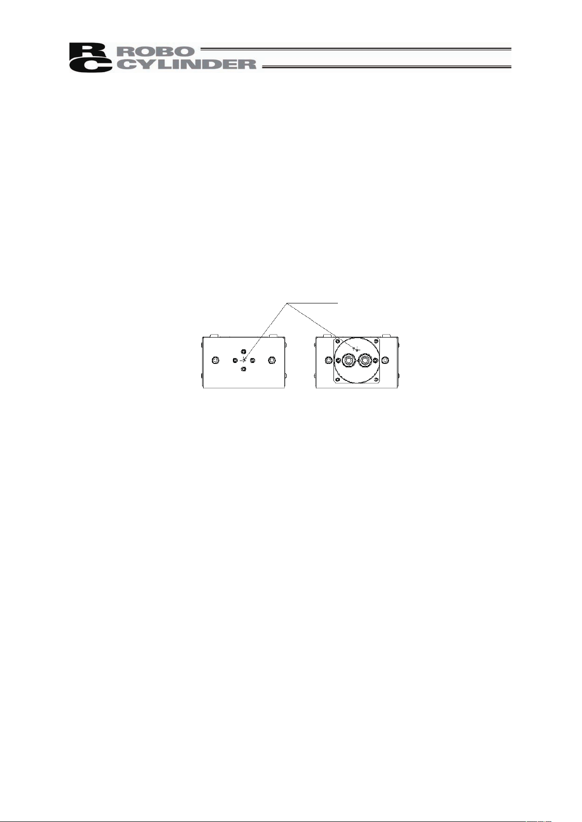
of the drop-proof function.
Filters
Page 16

10
International Standards Compliances
This actuator complies with the following overseas standards.
Refer to Overseas Standard Compliance Manual (ME0287) for more detailed information.
RoHS Directive CE Marking UL
{ {
×
Page 17
11
Names of the Parts
In this Operating Manual, the left and right sides are indicated by looking at the actuator from the
motor end, with the actuator placed horizontally, as shown in the figure below.
[Standard Type]
Right side
Left side
Actuator cable
Slider
Motor cover
Slider rod
Front side base plate
Guide rod
Motor side base plate
[With Cover Type]
Right side
Left side
Side cover
Motor cover
Actuator cable
Slider
Screw cover
Page 18

12
Page 19

13
1. Specifications Check
1.1 Checking the Product
The standard configuration of this product is comprised of the following parts.
See the component list for the details of the enclosed components. If you find any fault or missing
parts, contact your local IAI distributor.
1.1.1 Parts
No. Name Model number Quantity Remarks
1 Actuator
Refer to “How to Read the Model
Nameplate” and “How to Read
the Model Number.”
1
Accessories
2
Motor • encoder cables
(Note1)
1
3 Home mark sticker 1
4 First Step Guide 1
5 Operating Manual (DVD) 1
6 Safety Guide 1
Note1 The motor • encoder cables differ between the standard model and robot cable.
[Refer to 1.4, “Motor • Encoder Cables.”]
1.1.2 Related Operating Manuals for the Each Controller Supported by this Product
No. Name Control No.
1
Operating Manual for PCONC/CG/CF Controller
ME0170
2
Operating Manual for PCONCA/CFA Controller
ME0289
3
Operating Manual for RC PC Software RCM101MW/RCM101USB
ME0155
4
Operating Manual for CONPTA, CON-PDA, CON-PGA
ME0295
5 Operating Manual for Teaching Pendant CON-T, CON-TG ME0178
6
Operating Manual for Touch Panel Teaching CON-PT, CON-PD,
CON-PG
ME0227
1.1.3 How to Read the Model Nameplate
Model
Serial numbe
r
MODEL RCP2W-SA16C-I-86P-8-100-P2-S-NM
SERIAL No.800061910 A1 MADE IN JAPAN
1. Specications Check
Page 20

14
1.1.4 How to Read the Model Number
RCP2W㧙SA16C㧙I㧙86P㧙8㧙100㧙P2㧙S㧙NM
㧙
Note 1 Identification for IAI use only : It may be displayed for IAI use. It is not a code to show
the model type.
Series
<Type>
<Encoder type>
I : Incremental
<Motor type>
86P : Pulse Motor
56Ƒ High Output
<Lead>
4 : 4mm
8 : 8mm
Identification for IAI use only
(Note1)
<Options>
CO : With Cover Type
NM : Reversed-Home Type
<Cable length>
N : None
P : 1m
S : 3m
M : 5m
XƑƑ : Length specification
(Example: X07=7m)
RƑƑ : Robot cable
(Example: R05=5m)
<Controller>
P2 : PCON-CA
PCON-CFA
<Stroke>
[Refer to 1.2”Specifications”]
1. Specications Check
Page 21
15
1.2 Specification
1.2.1 Speed
Speed limits (Unit: mm/s)
Stroke [mm]
Motor Type Lead [mm]
Minimum
Speed
50 to 600 [Every 50mm ]
8 180
86P
4 1
3
3
1.2.2 Maximum Acceleration and Load Capacity
The Maximum Acceleration is 0.2G
Motor Type Lead [mm] Load Capacity [kg]
8 25
86P
4 35
Caution: Do not set speeds and accelerations/decelerations equal to or greater than the
respective ratings. Doing so may result in vibration, failure or shorter life.
If any acceleration/deceleration equal to or greater than the rated
acceleration/deceleration is set, a creep phenomenon or slipped coupling may
occur.
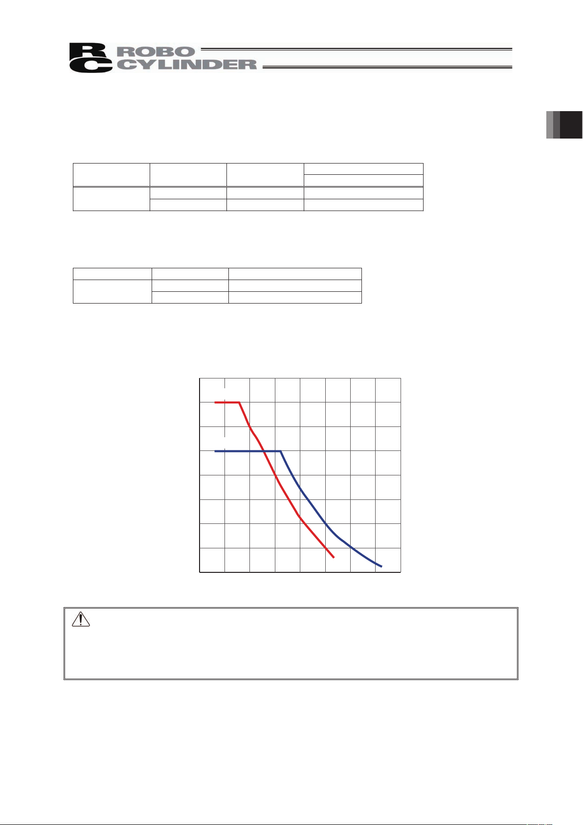
■Correlation diagram of speed and load capacity
For RCP2 Series, the load capacity will reduce
if the speed increases due to the characteristics of the
pulse motor. Confirm that the desired speed and
load capacity are satisfied from the graph below.
Speed [mm/sec]
40
35
30
25
20
15
10
5
0
0 25 50 75 100 125 150 175 200
Load capacity [kg]
Lead 4
Lead 8
1. Specications Check
Page 22

16
1.2.3 Driving System • Position Detector
Ball Screw Type
Motor Type Lead
No. of
Encoder
Pulses
Type Diameter Accuracy
8
86P
4
800 Rolled
I12
C10
1.2.4 Positioning repeatability
±0.08mm
* The values shown above are the accuracy at the delivery from the factory. It does not include the
consideration of time-dependent change as it is used.
1.2.5 Lost motion
0.7mm or less
* The values shown above are the accuracy at the delivery from the factory. It does not include the
consideration of time-dependent change as it is used.
1. Specications Check
Page 23

17
1.2.6 Load Moments of the Actuator
Allowable Static Load Moment
[N•m (Kgf•m)]
Allowable Overhang Load Length (L)
20 (2.04) Ma direction: 200, Mb or Mc direction
(Note 1)
Mb/Mc directions
Ma direction
Note 1 Avoid applying moment load to Mb or Mc direction during an operation.
1.2.7 Duty Ratio of Continuous Operation
During continuous operation, the actuator generates frictional heat due to sliding of the pipe over the
wear ring.
Since higher pipe temperatures reduce the clearance between the pipe and wear ring, shorten the
actuator life or cause other unwanted conditions, use the actuator at a duty of 50% or below.
Duty (%) = Operating time / (Operating time + Stopped time) × 100
1.2.8 Drop-proof Performance
Although the protection class is equivalent to IP67, there are some restrictions as shown below:
Ɣ Consult IAI beforehand, if the actuator will be used in an environment subject to splashes of liquids
other than water.
Ɣ The actuator cannot be used in an environment subject to splashes of viscous liquids.
Ɣ The actuator cannot be used in water.
Ɣ Structurally the actuator is designed to withstand washing with water, etc. However, the actuator
cannot be immersed in water, as it will cause the slide bushes to swell or create other unwanted
conditions.
1.2.9 Dust-proof Performance
The electrical parts of the actuator, such as its motor and encoder, are designed to completely shut off
dust. As for the moving parts (such as the sliding parts of the pipe and slider), the gaps are covered with
felt seals. Despite the above measures, however, dust may still enter the pipe and slider or underneath
the seals. Since such dust may damage the actuator or cause other unwanted conditions depending on
the type and state of dust, the actuator should not be used in the following environments:
Ɣ Environment where magnetic dust particles are dispersed or suspended
Ɣ Environment where polishing agent or other abrasive dust particles are dispersed or suspended
1. Specications Check
Page 24

18
1.3 Options
1.3.1 With Cover Type (Model: CO)
It is a cover to protect the guide part and slider part.
[Refer to 5. External Dimensions]
1.3.2 Reversed-Home Type (Model: NM)
The home position is normally set on the motor side, however, the home direction can be set opposite
by option if a reversed type is required due to such a reason as the layout of the system.
1. Specications Check
Page 25

19
1.4 Motor • Encoder Cables
1.4.1 Motor Cables
* The motor cable is a robot cable as standard.
CB-RCP2-MAƑƑƑ
1.4.2 Encoder Cables/Encoder Robot Cables
CB-RFA-PAƑƑƑ/CB-RFA-PAƑƑƑ-RB
A
VMM
B
A
VMM
B
A
VMM
A
B
VMM
B
I-1318119-3
(AMP)
SLP-06V
(JST)
A1
A2
A3
B1
B2
B3
1
2
3
4
5
6
(20) (8)
(15)
L
CN3
C
N
1
(φ8)
(28)
(14)
(14)
(20)
Min. Bending Radius = 50mm or more (Movable Use)
Electric
Wire Color
Signal
Name
Pin
No.
Width
Electric
Wire Color
Signal
Name
Pin
No.
Width
Orange
Gray
White
Yellow
Pink
Yellow (Green)
Yellow
Gray
Orange
Yellow (Green)
Pink
White
Controller Side Mechanical Side
(Front View) (Front View)
L
C
N
2
CN4
(5) (8) (13) (15)
(18)
(φ9)
(35)
(25)
(Reserved)
BK+
BKENA
ENA
ENB
ENB
VPS
GND
5V
F.G
16
15
14
13
12
11
10
9
8
7
6
5
4
3
2
1
1
2
3
4
5
6
7
8
9
10
11
12
13
14
15
16
17
18
ENA
ENA
ENB
ENB
GND
VPS
5V
BK+
BKF.G
Controller Side Mechanical Side
(Front View)
(Front View)
Electric Wire Color
Signal
Name
Pin
No.
Red
Gray
Brown
Green
Purple
Pink
-
Yellow
-
Blue
Orange
-
-
Ground
-
-
Orange (Black1)
Orange (Red1)
Light Gray (Black1)
Light Gray (Red1)
White (Black1)
White (Red1)
-
Yellow (Black1)
-
Pink (Black1)
Pink (Red1)
-
-
Ground
-
-
Brown
Green
Purple
Pink
-
-
-
-
Blue
-
Yellow
Orange
-
-
-
Red
Gray
Ground
Light Gray (Black1)
Light Gray (Red1)
White (Black1)
White (Red1)
-
-
-
-
Yellow (Black1)
-
-
-
Ground
Pink (Red1)
Pink (Red1)
Orange (Black1)
Orange (Red1)
-
Electric Wire Color
Signal
Name
Pin
No.
Robot Cable
Robot Cable
Standard Cable
Standard Cable
-
-
-
(Reserved)
(Reserved)
-
-
-
-
-
-
-
-
Min. Bending Radius = 50mm or more (Movable Use)
Housing: XMP-18V (JST)
Contact: BXA-001T-P0.6
Retainer: MS-09V
Housing: PHDR-16VS (JST)
Contact: SPHD-001T-P0.5
1. Specications Check
Page 26

2. Installation
20
2. Installation
2.1 Transportation
[1] Handling of the Robot
Unless otherwise specified, the actuators are packaged individually.
(1) Handling the Packed Unit
y Do not damage or drop. The package is not applied with any special treatment that enables it to
resist an impact caused by a drop or crash.
y An operator should never attempt to carry a heavy package on their own. Also, use an
appropriate way for transportation.
y Keep the unit in horizontal orientation when placing it on the ground or transporting. Follow the
instruction if there is any for the packaging condition.
y If the unit is held in a condition that the motor comes on the bottom by placing it tilted or in
vertical, the mechanic oil inserted inside the pipe may leak out, which may cause a malfunction
of the unit.
The same case will occur during the product unpackaged and installed.
y Do not step or sit on the package.
y Do not put any load that may cause a deformation or breakage of the package.
(2) Handling the Actuator After Unpacking
y Do not attempt to carry the actuator by holding a cable or move it by pulling a cable.
y Hold the base part and the bracket when transporting the actuator main body.
y Do not hit or drop the actuator during transportation.
y Do not give any excessive force to any of the sections in the actuator.
Slanted or vertical
position
Packed actuator
Horizontal position
Packed actuator
Page 27

21
[2] Handling in the Assembled Condition
This is the case when the product is delivered from our factory under a condition that it is
assembled with other actuators. The combined axes are delivered in a package that the frame is
nailed on the lumber base. The sliders are fixed so they would not accidently move. The
actuators are also fixed so the tip of it would not shake due to the external vibration.
(1) How to Handle in the Package
y Do not hit or drop the package. No special treatment is conducted on this package to endure a
drop or impact on it.
y Do not attempt to carry a heavy package with only one worker. Also, have an appropriate
method for transportation.
y When hanging up with ropes, support on the reinforcement frame on the bottom of the lumber
base. When bringing up the package with a forklift, also support on the bottom of the lumber
base.
y Handle with care when putting the package down to avoid impact or bounce.
y Do not step on the package.
y Do not put anything on the package that could deform or damage it.
(2) How to Handle after Unpackaged
y Fix the slider so they would not accidently move during transportation.
y If the tip of an actuator is overhanging, have an appropriate way to fix it to avoid shaking due to
the external vibration. In the transportation without the tip being fixed, do not apply any impact
with 0.3G or more.
y When hanging up with ropes, have appropriate cushioning to avoid any deformation of the
actuator body. Also keep it in stable horizontal orientation. Make a fixture utilizing the
attachment holes and the tapped holes on the actuator body if necessary.
y Do not attempt to apply load on the actuators or the connector box. Also pay attention not to
pinch cables and bend or deform them forcefully.
[3] Handling in Condition of being assembled in Machinery Equipment (System)
These are some caution notes for when transporting the actuator being assembled in the
machinery equipment (system):
y Fix the slider so they it would not move during transportation.
y If the tip of an actuator is overhanging, have an appropriate way to fix it to avoid shaking due to
the external vibration. In the transportation without the tip being fixed, do not apply any impact
with 0.3G or more.
y When hanging up the machinery equipment (system) with ropes, do not attempt to apply load on
the actuators or the connector box. Also pay attention not to pinch cables and bend or deform
them forcefully.
2. Installation
Page 28

2. Installation
22
2.2 Installation and Storage • Preservation Environment
[1] Installation Environment
The actuator should be installed in a location other than those specified below.
In general, the installation environment should be one in which an operator can work without
protective gear.
Also provide sufficient work space required for maintenance inspection.
y Where the actuator receives radiant heat from strong heat sources such as heat treatment
furnaces
y Where the ambient temperature exceeds the range of 0 to 40qC
y Where the temperature changes rapidly and condensation occurs
y Where the relative humidity exceeds 85% RH
y This actuator possesses the water durability of IP67 protection structure.
y Where the actuator receives direct sunlight
y Where the actuator is exposed to corrosive or combustible gases
y Where the ambient air contains a large amount of powder dust, salt or iron (at level exceeding
what is normally expected in an assembly plant)
y Where the actuator is subject to splashed oil (including oil mist or cutting fluid) or chemical
solutions
y Where the actuator receives impact or vibration
If the actuator is used in any of the following locations, provide sufficient shielding measures:
y Where noise generates due to static electricity, etc.
y Where the actuator is subject to a strong electric or magnetic field
y Where the actuator is subject to ultraviolet ray or radiation
[2] Storage Preservation Environment
y The storage and preservation environment should comply with the same standards as those for
the installation environment. In particular, when the machine is to be stored for a long time, pay
close attention to environmental conditions so that no dew condensation forms.
y Unless specially specified, moisture absorbency protection is not included in the package when
the machine is delivered. In the case that the machine is to be stored and preserved in an
environment where dew condensation is anticipated, take the condensation preventive
measures from outside of the entire package, or directly after opening the package.
y For storage and preservation temperature, the machine withstands temperatures up to 60qC for
a short time, but in the case of the storage and preservation period of 1 month or more, control
the temperature to 50qC or less.
y Storage and preservation should be performed in the horizontal condition. In the case it is stored
in the packaged condition, follow the posture instruction if any displayed on the package.
Page 29
23
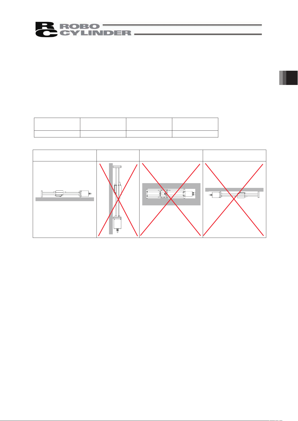
2.3 How to Install
This chapter explains how to install the actuator on your mechanical system.
2.3.1 General Rules on Installation
Follow the information below when installing the actuator, as a rule.
Do pay attention to these items (except with custom-order models).
{ : Possible u : Not possible
Horizontal
installation
Vertical
installation
Sideway
installation
Ceiling Mount
{
× × ×
Installation Orientation
Horizontal Ve
rtical Sideway Ceiling Mount
2. Installation
Page 30

2. Installation
24
2.3.2 Installation of the Main Unit
• The base plates on both ends of the actuator have through holes. Use these holes when installing the
actuator.
• For the platform to install the actuator on, ensure the structure has enough stiffness to avoid vibration
being generated.
• The surface where the actuator will be mounted should be machined or be equally level and the
flatness tolerance between the actuator and the table should be within 0.05mm/m.
• Provide enough space around the actuator to permit maintenance work to be done.
䎃
䎃
䎃
䎃
䎃
䎃
䎃
䎃
Caution: The actuator has no reference plane on its base, so do not use it in applications
where traveling precision is required.
For installation, refer to the table below and use hexagon socket-head bolts of the specification
appropriate for the material of the frame on which the actuator is installed.
Steel frame A
l
uminum frame
011 × 8M 001 × 8M
Use of high-tensile bolts conforming to ISO 10.9 or greater is recommended.
Recommended torque is 14 N⋅m (1.43 kgf⋅m).
4-9 drilled hole, φ14 counterbore depth 10
Page 31

25
2.3.3 Attachment of the Transported Object
• There are tapped holes on the top face of the slider. Affix the transported object here.
• There are two reamed holes on the top face of the slider. When repeatability in re-attaching is
required after it is detached, utilize these reamed holes. Also, use only one reamed hole on the slider
when fine-tuning such as perpendicularity is required.
Tapped hole
diameter
Tapping
depth
A B
T
ightening
Torque
M8 20mm 90mm
115mm
11.48N䍃m
Caution: Avoid applying moment loads in the Mb or Mc directions during an operation, and
make sure the load is distributed evenly on the slider.
There is a bushing made of a special plastic on the guide.
Applying a moment load may cause not only a twist or vibration on the slider, but
also shorten the life of the guide or drop in the speed due to the increase of sliding
resistance.
Tightening screws
• Use hexagonal socket head bolts for the male threads for installing the base.
• Use of high–tension bolts meeting at least ISO 10.9 is recommended.
• For the effective engagement length between the bolt and female thread, provide at least the
applicable value specified below:
Female thread is made of steel material ĺ Same length as the nominal diameter
Female thread is made of aluminum ĺ 2 times of nominal diameter
Caution: Pay attention when selecting the screw length. Use of a screw with inappropriate
length may destroy a tapped hole or cause a lack in the attachment strength of the
transported object, which may result in a cause of an unexpected accident.
Tapped hole Reamed hole
2. Installation
Page 32
26
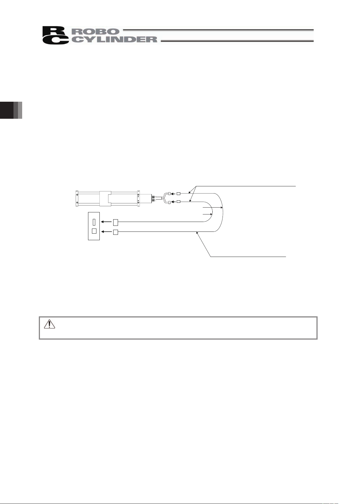
3. Connecting with the Controller
For the connection of an actuator to the controller, apply an IAI dedicated controller and dedicated
connection cable.
This section, describes how to connect with a single axis type.
• If the dedicated connection cable cannot be secured, reduce the load on the cable by allowing it to
deflect only by the weight of the cable or wire it in a self–standing cable hose, etc., having a large
radius.
• Do not cut and reconnect the dedicated connection cable for extension or shorten the cable.
• Do not pull on the dedicated connection cable or bend it forcibly.
• The actuator cable coming out of the motor unit is not meant to be bent. Fix the cable so it would not
be bent repeatedly.
Please consult with IAI if you require a different kind of cable than the one supplied.
Dedicated cables
x Motor cable (Robot cable) CB-RCP2-MAƑƑƑ
x Encoder cable CB-RFA-PAƑƑƑ/ Robot encoder cable CB-RFA-PAƑƑƑ-RB
ƑƑƑ indicates the cable length. A desired length up to 20m can be specified.
Example) 080 = 8m
Caution: The cable joint connector is not drop-proofed. Make the connection at an area
considering water would not be splashed.
Dedicated Connection Cable
(Connect RCS2W with the dedicated controller.)
r
r
Dedicated Controller
PCON-CF
PCON-CFA
Robot Cable
r = 54mm or more (Movable Use)
Standard Cable
r = 75mm or more (Fixed Use)
Use robot cables if the cables tend to move.
3. Connecting with the Controller
Page 33
27
Warning: For wiring, please follow the warnings stated below. When constructing a
system as the machinery equipment, pay attention to the wiring and
connection of each cable so they are conducted properly. Not following them
may cause not only a malfunction such as cable breakage or connection
failure, or an operation error, but also electric shock or electric leakage, or
may even cause a fire.
• Use dedicated cables of IAI indicated in this instruction manual. Contact us if you
wish to have a change to the specifications of the dedicated cables.
• Make sure to turn the power off in the process of power line or cable connection or
disconnection.
• Do not attempt to cut a dedicated cable with connectors on both ends to extend,
shorten or re-joint it.
• Hold the dedicated cable to avoid mechanical force being applied to the terminals and
connectors.
• Use a cable pipe or duct to have an appropriate protection when there is a possibility
of mechanical damage on a dedicated cable.
• In case a dedicated cable is to be used at a moving part, make sure to lay out the
cable without applying any force to pull the connector or extreme bend on the cable.
Do not attempt to use the cable with a bending radius below the allowable value.
• Make certain that the connectors are plugged properly. Insufficient connection may
cause an operation error, thus it is extremely risky.
• Do not lay out the cables to where the machine runs over them.
• Pay attention to the cable layout so it will not hit peripherals during an operation. In
case it does, have an appropriate protection such as a cable track.
• When a cable is used hanging on the ceiling, presenting an environment that the
cable swings with acceleration or wind velocity.
• Make sure there is not too much friction inside the cable storage equipment.
• Do not apply radiated heat to power line or cables.
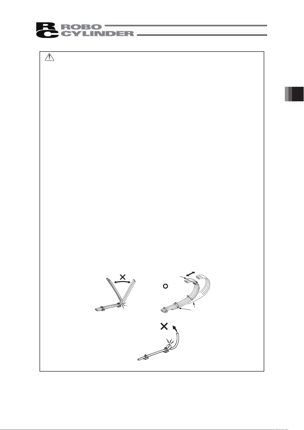
• Have a sufficient radius for bending, and avoid a bend concentrating on one point.
Steel Strap
(Piano Wire)
Tie them up softly.
• Do not let the cable bend, kink or twist.
3. Connecting with the Controller
Page 34
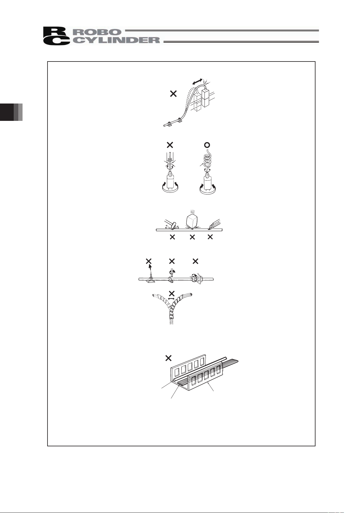
28
• Do not pull the cable with a strong force.
• Pay attention not to concentrate the twisting force to one point on a cable.
• Do not pinch, drop a heavy object onto or cut the cable.
• When a cable is fastened to affix, make sure to have an appropriate force and do not
tighten too much.
Do not use spiral tube in any
position where cables are bent
frequently.
• PIO line, communication line, power and driving lines are to be put separately from
each other and do not tie them together. Arrange so that such lines are independently
routed in the duct.
Power Line
Duct
I/O Line
(Flat Cable, etc.)
3. Connecting with the Controller
Page 35
29
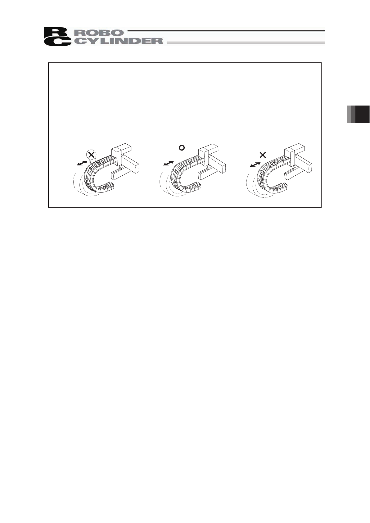
Follow the instructions below when using a cable track.
• If there is an indication to the cable for the space factor in a cable track, refer to the
wiring instruction given by the supplier when storing the cable in the cable track.
• Avoid getting cables twined or twisted in the cable track, and also having the cables
move freely and do not tie them up. (Avoid tension being applied when the cables are
bent.)
Do not pile up cables. It may cause faster abrasion of the sheaths or cable breakage.
3. Connecting with the Controller
Page 36

30
4. Maintenance Inspection
4.1 Inspection Items and Schedule
Follow the maintenance inspection schedule below.
It is assumed that the equipment is operating 8 hours per day.
If the equipment is running continuously night and day or otherwise running at a high operating rate,
inspect more often as needed.
External visual inspection Greasing
(Note 1)
Start of work inspection
{
1–month inspection
{
6-month inspection
{
12-month inspection
{
{
Every 6 months thereafter
{
Every 12 months thereafter
{ {
Note 1 • In an environment that the product is exposed in steam or hot water, earlier consumption of
grease is concerned. It is recommended to supply grease earlier.
• If the actuator are operated back and forth repeatedly over a distance of 30mm or less, the
oil film created by the grease may be broken. As a guide, move the actuators back and forth
repeatedly for around 5 cycles over a distance of 50mm or more after every 5,000 to 10,000
cycles. A layer of the grease will recover.
4.2 External Visual Inspection
An external visual inspection should check the following things.
䎃
Main unit Loose actuator mounting bolts, other loose items
Slider rod Lubricationg condition of grease, scratches on pipe
surface, deformation
Guide rod Scratchs on pipe surface, deformation
Cables Scratches, proper connections
Overall Irregular noise, vibration
䎃
4.3 Grease Supply
4.3.1 Grease applied on the Slider Rod
IAI uses the following grease in our plant.
Taiyo Petroleum Gas MEDALLION FM1(antibacterial grease)
Apart from above, there are equivalent sorts of grease sold in the market. For more detailed information,
ask the supplier to find an equivalent for you by telling them the name of the grease.
Warning: Do not attempt to apply fluorine and lithium grease. When mixed with lithium
grease, not only decrease the grease characteristics, but also may damage the
actuator.
4. Maintenance Inspection
Page 37

31
4.3.2 How to apply the grease
Since the pipe and slider are designed to slide against each other via a wear ring, food-grade grease is
charged as lubricant in order to extend the life of the wear ring and keep the pipe temperature from
rising.
This grease contains antibacterial agent to prevent growth of bacteria and mildews. It also offers strong
adhesive power to withstand the flushing forces of high-pressure water. However, the grease will still be
consumed over time due to actuator operation, washing with water, and so on. If necessary, therefore,
apply grease during the inspection.
If the actuator had not been operated for a prolonged period of time, apply grease before operating it
again.
[How to Add Grease]
If the actuator has a screw cover, remove the cover.
Clean the surface of the slider rod, and apply grease over the entire surface using your finger.
To reach inaccessible areas of the slider, turn on the power and move the slider until the applicable
areas are exposed. Then, turn off the power and apply grease.
Also apply grease over the guides on both sides
Caution: In case the grease got into your eye, immediately go see the doctor to get
appropriate care.
After finishing the grease supply work, wash your hands carefully with water
and soap to rinse the grease off.
4. Maintenance Inspection
Page 38

32
5. External Dimensions
5.1 Without cover specification
5.2 With cover specification (Option)
Stroke 50 100 150 200 250 300 350 400 450 500 550 600
L 490 540 590 640 690 740 790 840 890 940 990 1040
A 335 385 435 485 535 585 635 685 735 785 835 885
B 305 355 405 455 505 555 605 655 705 755 805 855
S 50 100 150 200 250 300 350 400 450 500 550 600
Without cover weight [kg] 9 9.4 9.9 10.4 10.9 11.3 11.8 12.3 12.7 13.2 13.7 15.1
With cover weight [kg] 10.5 11.1 11.8 12.5 13.2 13.8 14.6 15.3 15.9 16.6 17.3 18.9
15
20
20
15
φ90
155
(2m)
90
130
A
B
L
65
65
4-9 Drilled Hole,
φ14 Counterbore, Depth 8.5
2-φ8H7 Depth 10
S(Stroke)
HOME
30
125
53
25
5
130
4-M8 Depth 20
105
80
5225
115
100
158
4
Cable Joint
Connector
Actuator cable
(material A50 52P)
Base Plate Base Plate
Slider Slider Rod
Guide Rod
(material A 6N01S-T15) (material S US304) (material A50 52P)
(material S US304)
MOTOR COVER
(material A 6063S)
SEME
ME
4.3
±0.2
7.3
±0.2
8
6.5
2
A
DETAIL: A
Cover
(material S US304)
ME : Mechanical End
SE : Stroke End
15
20
20
15
φ
90
155
90
130
A
B
L
65
65
4-9 Drilled Hole,
φ
14 Counterbore, Depth 8.5
2-
φ
8H10 Depth 10
S(Stroke)
30
125
78
5
130
4-M8 Depth 20
105
80
77
4
115
101.5
166
Home
ME
SEME
5. External Dimensions
Page 39
33
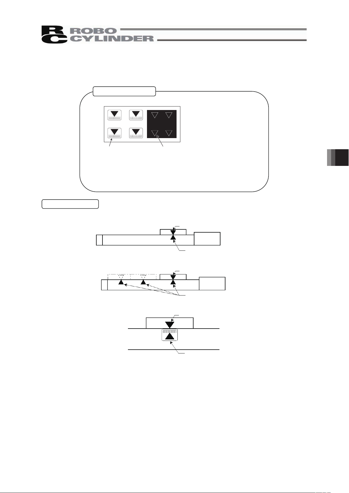
6. How to use the home mark
Please affix these marks to the actuator as home markers as needed.
Home mark sticker
Home mark scale × 4 Home mark × 4
(Scale: 1 mm graduation mark, 10 mm width)
• Peel off the marks from the base sheet.
Note 1. Every mark has sticky back.
2. Remove smear and stain from the surface.
3. Avoid label or nameplate as a marking location.
Contents of sticker
× 1 sheet
Example of Use
1) Used to indicate the direction of actuator home
On the slider
On the base near home position
Motor
2) Used as stop positions
Motor
On the slider
At stop positions on the base
3) Used for position deviation check
On the base
On the slider
• Place the marks when the actuator is stopped at home position.
6. How to use the home mark
Page 40

7. Life
34
7. Life
The product life is assumed to be 5,000km (reference) under the condition that it runs with maximum
load capacity and maximum acceleration/deceleration.
Page 41

35
8. Warranty
8.1 Warranty Period
One of the following periods, whichever is shorter:
y 18 months after shipment from IAI
y 12 months after delivery to the specified location
y 2,500 hours of operation
8.2 Scope of the Warranty
Our products are covered by warranty when all of the following conditions are met. Faulty products
covered by warranty will be replaced or repaired free of charge:
(1) The breakdown or problem in question pertains to our product as delivered by us or our authorized
dealer.
(2) The breakdown or problem in question occurred during the warranty period.
(3) The breakdown or problem in question occurred while the product was in use for an appropriate
purpose under the conditions and environment of use specified in the instruction manual and
catalog.
(4) The breakdown of problem in question was caused by a specification defect or problem, or by a
quality issue with our product.
Note that breakdowns due to any of the following reasons are excluded from the scope of warranty:
[1] Anything other than our product
[2] Modification or repair performed by a party other than us (unless we have approved such
modification or repair)
[3] Anything that could not be easily predicted with the level of science and technology available
at the time of shipment from our company
[4] A natural disaster, man-made disaster, incident or accident for which we are not liable
[5] Natural fading of paint or other symptoms of aging
[6] Wear, depletion or other expected result of use
[7] Operation noise, vibration or other subjective sensation not affecting function or maintenance
Note that the warranty only covers our product as delivered and that any secondary loss arising from a
breakdown of our product is excluded from the scope of warranty.
8.3 Honoring the Warranty
As a rule, the product must be brought to us for repair under warranty.
8.4 Limited Liability
(1) We shall assume no liability for any special damage, consequential loss or passive loss such as a
loss of expected profit arising from or in connection with our product.
(2) We shall not be liable for any program or control method created by the customer to operate our
product or for the result of such program or control method.
8. Warranty
Page 42

8. Warranty
36
8.5 Conditions of Conformance with Applicable Standards/Regulations, Etc., and Applications
(1) If our product is combined with another product or any system, device, etc., used by the customer,
the customer must first check the applicable standards, regulations and/or rules. The customer is
also responsible for confirming that such combination with our product conforms to the applicable
standards, etc. In such a case we will not be liable for the conformance of our product with the
applicable standards, etc.
(2) Our product is for general industrial use. It is not intended or designed for the applications
specified below, which require a high level of safety. Accordingly, as a rule our product cannot be
used in these applications. Contact us if you must use our product for any of these applications:
[1] Medical equipment pertaining to maintenance or management of human life or health
[2] A mechanism or mechanical equipment intended to move or transport people (such as a
vehicle, railway facility or aviation facility)
[3] Important safety parts of mechanical equipment (such as safety devices)
[4] Equipment used to handle cultural assets, art or other irreplaceable items
(3) Contact us at the earliest opportunity if our product is to be used in any condition or environment
that differs from what is specified in the catalog or instruction manual.
8.6 Other Items Excluded from Warranty
The price of the product delivered to you does not include expenses associated with programming, the
dispatch of engineers, etc. Accordingly, a separate fee will be charged in the following cases even
during the warranty period:
[1] Guidance for installation/adjustment and witnessing of test operation
[2] Maintenance and inspection
[3] Technical guidance and education on operating/wiring methods, etc.
[4] Technical guidance and education on programming and other items related to programs
Page 43

37
Change History
Revision Date Description of Revision
April 2011
March 2012
February 2013
Fourth edition
A page for CE Marking added
Fifth edition
P1 to 7:
Contents added and changed in Safety Guide
P8: Caution in Handling added
P10 to 11: Contents changed in 3. Warranty
P23: Warning notes added such as in case the grease got into
your eye, immediately go to see the doctor for an
appropriate care.
P24: External Dimensions added
Sixth edition
Revised overall
Change History
Page 44

Page 45

Page 46

Manual No.: ME3651-6A (February 2013)
The information contained in this document is subject to change without notice for purposes of
product improvement.
Copyright © 2013. Feb. IAI Corporation. All rights reserved.
13.02.000
Head Office: 577-1 Obane Shimizu-KU Shizuoka City Shizuoka 424-0103, Japan
TEL +81-54-364-5105 FAX +81-54-364-2589
website: www.iai-robot.co.jp/
Ober der Röth 4, D-65824 Schwalbach am Taunus, Germany
TEL 06196-88950 FAX 06196-889524
SHANGHAI JIAHUA BUSINESS CENTER A8-303, 808, Hongqiao Rd. Shanghai 200030, China
TEL 021-6448-4753 FAX 021-6448-3992
website: www.iai-robot.com
Technical Support available in USA, Europe and China
Head Office: 2690 W. 237th Street, Torrance, CA 90505
TEL (310) 891-6015 FAX (310) 891-0815
Chicago Office: 1261 Hamilton Parkway, Itasca, IL 60143
TEL (630) 467-9900 FAX (630) 467-9912
TEL (678) 354-9470 FAX (678) 354-9471
website: www.intelligentactuator.com
Atlanta Office: 1220 Kennestone Circle, Suite 108, Marietta, GA 30066
 Loading...