

Page 1

RCP2 Series
ROBO Cylinder Controller
Operation Manual Fifteenth Edition
Sixteenth Edition
Page 2

Page 3

Please Read Before Use
Thank you for purchasing our product.
This Operation Manual explains the handling methods, structure and maintenance of this product, among others,
providing the information you need to know to use the product safely.
Before using the product, be sure to read this manual and fully understand the contents explained herein to
ensure safe use of the product.
The CD that comes with the product contains operation manuals for IAI products.
When using the product, refer to the necessary portions of the applicable operation manual by printing them out
or displaying them on a PC.
After reading the Operation Manual, keep it in a convenient place so that whoever is handling this product can
reference it quickly when necessary.
[Important]
This Operation Manual is original.
The product cannot be operated in any way unless expressly specified in this Operation Manual. IAI
shall assume no responsibility for the outcome of any operation not specified herein.
Information contained in this Operation Manual is subject to change without notice for the purpose of
product improvement.
If you have any question or comment regarding the content of this manual, please contact the IAI
sales office near you.
Using or copying all or part of this Operation Manual without permission is prohibited.
The company names, names of products and trademarks of each company shown in the sentences
are registered trademarks.
Page 4

CAUTION
1. 24-V Power Supplies for Equipment Requiring a UL Certification
[1] The controller with the maximum current of 2 A (RCP2-C/CG) and 6 A (RCP2 -C F) are UL-certified.
However, a UL certification requires that the 24-V power supplies used with the controller conform to
Class 2.
If the user’s equipment must receive a UL certification, please use an input power supply and an I/O
power supply both conforming to Class 2.
[2] RCP2 controller can be us ed in the environment of the pollution degree 2.
2. Basic Parameter Settings
After applying power, at least the three parameters specified below must be set in accordance with the
specific application.
Inappropriate
For details on how to set the parameters, refer to “Parameter Settings” in the operation manual for the PC
or teaching pendant.
[1] Selecting the PIO pattern
This controller provides six PIO (Parallel I/O) patterns to meet the needs of various applications.
To select a desired PIO pattern, set a corresponding value from 0 to 5 in parameter No. 25 (PIO
pattern selection).
The factory setting is “0.”settings of these parameters will prevent the controller from operating properly,
No. 25 setting
so exercise due caution.
Parameter
0
Conventional
This pattern is compatible with the pin assignments of the RCP controller.
1
Standard
All functions of the RCP controller are available, plus the home-return command input, servo
ON input, reset input, moving output and ready output.
2
64-point positioning
Compared with the standard pattern offering only 16 positioning points, this pattern provides up
to 64 positioning points.
However, the servo ON input, ready output and zone output have been removed.
3
2 zone output signals
Compared with the standard pattern offering only one zone output signal, this pattern provides
two zone output signals.
However, the moving output has been removed.
The boundaries for the second zone output signal are specified in parameter Nos. 23 and 24.
4
Teaching
This pattern allows for normal positioning operation, as well as jogging and writing of current
position to a specified position using I/Os.
Switching between the normal positioning mode and teaching mode is effected by the MODE
input signal.
The mode switching completion output has been added to indicate that the modes have been
switched.
However, the zone output has been removed.
(Note) Position data can be rewritten up to around 100,000 times.
5
4 points (air cylinder)
Use of the RCP2 as an air cylinder is assumed in this pattern.
The number of positioning points is limited to four, but a direct command input and a position
complete output are provided for each target position in line with the conventional practi ce of air
cylinder control.
This lets the user control the RCP2 just like an air cylinder.
Feature of PIO pattern
Page 5

[2] Enabling/disabling the servo ON input signal (SON)
The servo ON input signal has been added to allow for servo ON/OFF control on the PLC side. Depending
on the needs, therefore, the user must enable/disable this signal.
To select a desired setting, set “0” or “1” in parameter No. 21 (Servo ON input disable selection).
Enable (use) the signal 0
Disable (do not use) the signal 1
If “0” or “2” has been selected as the above PIO pattern, the servo ON signal is not provided. However, you
must still set “1: [Disable]” in parameter No. 21 (SON). (If “0” is set, the servo will not turn ON.)
The factory setting for this parameter is “1: [Disable].”
[3] Enabling/disabling the pause signal (*STP)
The pause signal uses the contact B logic to provide a failsafe function.
Therefore, this signal must remain ON in normal conditions of use.
(The pause signal must also remain ON when issuing movement commands from the teaching pendant or
PC.)
Since there are applications where this signal is not used, a parameter is provided to disable the pause
signal so it doesn’t have to be turned ON.
To select a desired setting, set “0” or “1” in parameter No. 15 (Pause input disable selection).
Enable (use) the signal 0
Disable (do not use) the signal 1
If the pause input is not used, set “1: [Disable]” in this parameter and the signal need not be turned ON.
The factory setting for this parameter is “0: [Enable].”
3. Recommendation for Backing up Latest Data
This controller uses nonvolatile memory to store the position table and parameters. Normally the memory
will retain the stored data even after the power is disconnected. However, the data may be lost if the
nonvolatile memory becomes faulty.
We strongly recommend that the latest position table and parameter data be backed up so that the data can
be restored quickly in the event of power failure, or when the controller must be replaced for a given reason.
The data can be backed up using the following methods:
[1] Save to a CD or FD from the PC software.
[2] Hand write the position table and parameter table on paper.
4. Compatibility of Teaching Pendant
The existing teaching pendants of <RCA-T> and <RCA-E> types can be used with the RCP2 controlle r, but
your RCA-T/RCA-E teaching pendant will require some modification.
If you are using a teaching pendant of either type, please send it to IAI. We will perform the necessary
modification and return it to you as soon as possible.
Teaching pendants that have already been modified have a specific code at the end of their serial number.
Please check the serial number of your teaching pendant to see if it requires modification.
Teaching pendant model number Code at the end of serial number
RCA-T …F3 (or later)
RCA-E …H3 (or later)
RCA-P …H3 (or later)
RCB-J …B2 (or later)
5. PC Software Versions
The software versions that support this controller are 4.0.0.0 and later.
Page 6

CE Marking
If a compliance with the CE Marking is required, please follow Overseas Standards Compliance Manual
(ME0287) that is provided separately.
Page 7

Table of Contents
Safety Guide.................................................................................................1
1. Overview..............................................................................................1
1.1 Introduction..................................................................................................................................... 1
1.2 How to Read Model Number..........................................................................................................2
1.3 Handling of Secondary Batteries for the Absolute Specification.................................................... 3
1.4 Safety Precautions.........................................................................................................................4
1.5 Warranty Period and Scope of Warranty........................................................................................5
2. Specifications.......................................................................................6
2.1 Basic Specifications........................................................................................................................6
2.1.1 Backup Batteries for the Absolute Specification...................................................................... 7
2.1.2 Specifications of the Large-Capacity Type (RCP2-CF)...........................................................8
2.2 Name and Function of Each Part of the Controller........................................................................9
2.2.1 Names.....................................................................................................................................9
2.2.2 Functions.................................................................................................................................9
2.3 External Dimensions .................................................................................................................... 11
2.3.1 Standard Specification........................................................................................................... 11
2.3.2 Absolute Specification with Battery Bracket..........................................................................12
Absolute Specification without Battery Bracket ..............................................................................13
2.3.3 Large-Capacity Type (RCP2-CF-***)..................................................................................... 14
3. Installation and Noise Elimination......................................................15
3.1 Installation Environment...............................................................................................................15
3.2 Power Supply...............................................................................................................................15
3.3 Noise Elimination and Grounding.................................................................................................15
3.4 Heat Radiation and Installation....................................................................................................17
4. Wiring.................................................................................................18
4.1 Internal Drive-Power Cutoff Relay T ype (RCP2-C, RCP2-CF).................................................... 18
4.1.1 Configuration.........................................................................................................................18
4.1.2 External Connection Diagram ...............................................................................................19
4.1.3 Wiring the Power Supply/Emergency-Stop Switch ...............................................................20
4.2 External Drive-Power Cutoff Relay Type (RCP2-CG)..................................................................27
4.2.1 Configuration.........................................................................................................................27
4.2.2 External Connection Diagram ...............................................................................................28
4.2.3 Wiring the Power Supply/Motor Power Cutoff Relay.............................................................29
4.3 Connecting the I/O Cables........................................................................................................... 32
PIO pattern 0 [Conventional].................................................................................................32
PIO pattern 1 [Standard]........................................................................................................33
PIO pattern 2 [64-point positioning]....................................................................................... 34
Page 8

PIO pattern 3 [2 zone output signals]....................................................................................35
PIO pattern 4 [Teaching]........................................................................................................36
PIO pattern 5 [4 points] (air cylinder).....................................................................................37
4.4 Connecting the Actuator...............................................................................................................38
4.4.1 Motor Extension Cable.......................................................................................................... 38
4.4.2 Encoder Extension Cable......................................................................................................39
[Standard controller (2 A)]......................................................................................................39
[Large-capacity controller (6 A)]............................................................................................41
4.5 Connecting the Communication Cable.........................................................................................42
5. I/O Signal Control and Signal Functions............................................43
5.1 PIO Patterns and Signal Assignments......................................................................................... 43
5.1.1 Explanation of Signal Names................................................................................................44
PIO pattern = “0: [Conventional],” “1: [Standard],” “2: [64-point positioning],” “3: [2 zone output
signals]”.................................................................................................................................44
PIO pattern = “4: [Teaching]”.................................................................................................45
PIO pattern = “5: [4 points].................................................................................................... 46
5.1.2 Signal Assignment T able for Respective PIO Patterns.........................................................47
5.2 Interface Circuit............................................................................................................................48
5.2.1 External Input Specifications.................................................................................................48
5.2.2 External Output Specifications..............................................................................................49
5.3 Details of I/O Signal Functions.....................................................................................................50
5.3.1. Details of Each Input Signal............................................................................................50
Start (CSTR).......................................................................................................................... 50
Command position number (PC1 to PC32)...........................................................................50
Pause (*STP)........................................................................................................................50
Home return (HOME)............................................................................................................51
Servo ON (SON) ................................................................................................................... 51
Alarm reset (RES)................................................................................................................. 51
Operation mode (MODE) ......................................................................................................51
Current-position write (PWRT)..............................................................................................52
Jog (JOG+, JOG-).................................................................................................................52
Movement to each position (ST0 to ST3)..............................................................................52
5.3.2 Details of Each Output Signal...............................................................................................53
Completed position numb er (PM1 to P M32)......................................................................... 53
Moving (M OVE).....................................................................................................................53
Position complete (PEND).....................................................................................................53
Home return completion (HEND).......................................................................................... 53
Zone (ZONE1, ZONE2).........................................................................................................54
Current operation mode (MODES)........................................................................................54
Write completion (WEND).....................................................................................................54
Completion of each position (PE0 to PE3)............................................................................54
Ready (SRDY).......................................................................................................................55
Alarm (*ALM)......................................................................................................................... 55
Emergency stop (*EMGS).....................................................................................................55
(Reference) Output Signal Changes in Each Mode..................................................................... 55
Page 9

6. Data Entry <Basics>..........................................................................56
6.1 Description of Position-Data Table...............................................................................................57
6.1.1 Relationship of Push Force at Standstill and Current-Limiting Value.................................... 60
(1) SA5/SA6/SS type (2) SA7 type............................................................................................. 60
(3) SM type .................................................................................................................................61
(1) RP A type (2) RXA type.......................................................................................................... 62
(3) RSA/RSW type (4) RMA/RMW type ..................................................................................... 63
(5) RFA/RFW type......................................................................................................................64
6.2 Explanation of Modes................................................................................................................... 65
6.2.1 Positioning Mode Push = 0 ................................................................................................... 65
6.2.2 Push & Hold Mode Push = Other than 0...............................................................................65
6.2.3 Speed Change during Movement..........................................................................................67
6.2.4 Operation at Different Acceleration and Deceleration Settings.............................................67
6.2.5 Pause ....................................................................................................................................68
6.2.6 Zone Signal Output ............................................................................................................... 69
6.2.7 Home Return......................................................................................................................... 69
6.2.8 Teaching Mode (Jogging/Teaching Using PIO).....................................................................70
6.2.9 Overview of the “4 Points” (Air Cylinder) Mode.....................................................................71
6.3 Notes on the ROBO Gripper........................................................................................................73
7. Operation <Practical Steps>..............................................................75
7.1 How to Start..................................................................................................................................75
7.1.1 Standard Specification........................................................................................................... 75
7.1.2 Absolute Specification (Absolute Reset)............................................................................... 77
7.2 How to Execute Home Return......................................................................................................80
7.2.1 Standard Specification........................................................................................................... 80
7.2.2 Absolute Specification........................................................................................................... 81
7.2.3 Operation Timings at PIO Pattern = “0: [Conventional]”........................................................82
7.2.4 Operation Timings at PIO Pattern = “5: [4 Points]”................................................................83
7.2.5 Operation Timings at PIO Pattern ≠ “0: [Conventional]” or “5: [4 Points]”..........................84
7.3 Home Return and Movement after Start (PIO Pattern = “1: [Standard]”)..................................85
7.4 Positioning Mode (Back and Forth Movement between Two Points)...........................................87
7.5 Push & Hold Mode .......................................................................................................................89
7.5.1 Return Action after Push & Hold by Relative Coordinate Specification ................................90
7.6 Speed Change during Movement.................................................................................................91
7.7 Operation at Different Acceleration and Deceleration Settings.................................................... 93
7.8 Pause ...........................................................................................................................................95
7.9 Zone Signal Output ......................................................................................................................97
.10 Incremental Moves.......................................................................................................................99
7.11 Notes on Incremental Mode....................................................................................................... 101
7.12 Jogging/Teaching Using PIO...................................................................................................... 103
8. Parameters ......................................................................................109
8.1 Parameter Classification ............................................................................................................109
8.2 Parameter Table.........................................................................................................................109
8.3 Parameter Settings..................................................................................................................... 110
8.3.1 Parameters Relating to the Actuator S troke Range............................................................ 110
Page 10

Soft limit............................................................................................................................... 110
Zone boundary.................................................................................................................... 110
Home return direction...........................................................................................................111
Home return offset................................................................................................................111
8.3.2 Parameters Relating to the Actuator Operating Characteristics..........................................111
PIO jog speed.......................................................................................................................111
Default speed.......................................................................................................................111
Default acceleration/deceleration.........................................................................................111
Default positioning band (in-position).................................................................................. 112
Default acceleration only MAX flag..................................................................................... 112
Push & hold stop judgment period...................................................................................... 112
Current-limiting value at standstill during positioning.......................................................... 113
Current-limiting value during hom e return........................................................................... 113
Direction of excitation phase signal detection..................................................................... 113
8.3.3 Parameters Relating to the External Interface.................................................................... 114
PIO pattern selection........................................................................................................... 114
Movement co mmand type................................................................................................... 115
Pause input disable selection.............................................................................................. 116
Servo ON input disable selection........................................................................................ 116
Serial communication speed............................................................................................... 116
Minimum delay time for slave transmitter activation........................................................... 116
8.3.4 Servo Gain Adjustment........................................................................................................ 116
Servo gain number.............................................................................................................. 116
9. Controlling Multiple Controllers via Serial Communication ..............117
9.1 Basic Specifications.................................................................................................................... 117
9.2 Connection Example..................................................................................................................117
9.3 SIO Converter ............................................................................................................................ 118
9.4 Address Switch...........................................................................................................................120
9.5 Connection Cables.....................................................................................................................120
9.6 Detail Connection Diagram ........................................................................................................121
10. Troubleshooting...............................................................................122
10.1 Action to Be Taken upon Occurrence of Problem......................................................................122
10.2 Alarm Level Classification..........................................................................................................123
10.3 Alarm Description Output Using PIO..........................................................................................124
10.4 Alarm Description and Cause/Action .........................................................................................125
(1) Message level alarms..........................................................................................................125
(2) Operation-cancellation level alarms.................................................................................... 126
(3) Cold-start level alarms.........................................................................................................129
10.5 Messages Displayed during Operation Using the Teaching Pendant or PC Software .............. 131
10.6 Specific Problems.......................................................................................................................133
I/O signals cannot be exchanged with the PLC. .................................................................133
The RDY lamp does not illuminate after the power is input................................................133
Only the RDY lamp illuminates when the servo ON signal is input after the power was input.133
Both the RDY lamp and ALM lamp illuminate when the power is input.............................. 133
Home return ends in the middle in a vertical application. ................................................... 134
Page 11

Noise occurs during downward movements in a vertical application..................................134
Vibration occurs when the actuator is stopped. ..................................................................134
The actuator overshoots when decelerated to a stop.........................................................134
The home and target positions sometimes shift..................................................................134
The speed is slow during push & hold operation................................................................134
The actuator moves only a half of, or twice as much as, the specified movement.............135
A servo error occurred while the actuator was moving (ROBO Gripper)............................135
Abnormal operation results when the servo is turned ON after the power ON................... 136
Abnormal noise is heard from a controller of absolute specification upon completion of home return.
.............................................................................................................................................136
The ALM lamp blinks when the power is cut off..................................................................136
11. Function Check and Replacement of the Radiating Fan .................137
12. Replacing the Absolute Data Retention Battery...............................139
* Appendix.................................................................................................141
List of Supported Actuator Specifications..................................................141
Example of Basic RCP2 Positioning Sequence........................................151
Recording of Position-Data Table...........................................................................................................154
Recording of Parameters....................................................................................................................... 156
Change History.........................................................................................157
Page 12

Page 13

Safety Guide
This “Safety Guide” is intended to ensure the correct use of this product and prevent dangers and prope rty
damage. Be sure to read this section before using your product.
Regulations and Standards Governing Industrial Robots
Safety measures on mechanical devices are generally classified into four categori es un der the International
Industrial Standard ISO/DIS 12100, “Safety of machinery,” as follows:
Safety measures Inherent safety design
Protective guards --- Safety fence, etc.
Additional safety measures --- Emergency stop device, etc.
Information on use --- Danger sign, warnings, operation manual
Based on this classification, various standards are established in a hierarchical manner under the International
Standards ISO/IEC. The safety standards that apply to industrial robots are as follows:
Type C standards (individual safety standards) ISO10218 (Manipulating industrial robots – Safety)
JIS B 8433
(Manipulating industrial robots – Safety)
Also, Japanese laws regulate the safety of industrial robots, as follows:
Industrial Safety and Health Law Article 59
Workers engaged in dangerous or harmful operations must receive special education.
Ordinance on Industrial Safety and Health
Article 36 --- Operations requiring special education
No. 31 (Teaching, etc.) --- Teaching and other similar work involving industrial robots (exceptions
apply)
No. 32 (Inspection, etc.) --- Inspection, repair, adjustment and similar work involving industrial robots
(exceptions apply)
Article 150 --- Measures to be taken by the user of an industrial robot
Pre-1
Page 14

Requirements for Industrial Robots under Ordinance on Industrial Safety and
Health
Work area
movement
range
Inside
movement
range
Work
condition
During
automatic
operation
During
teaching, etc.
During
inspection,
etc.
Cutoff of drive source Measure Article
Signs for starting operation Article 104 Outside
Not cut off
Cut off (including
stopping of operation)
Not cut off
Cut off
Not cut off (when
inspection, etc., must
be performed during
operation)
Installation of railings, enclosures,
etc.
Sign, etc., indicating that work is in
progress
Preparation of work rules Article 150-3
Measures to enable immediate
stopping of operation
Sign, etc., indicating that work is in
progress
Provision of special education Article 36-31
Checkup, etc., before
commencement of work
To be performed after stopping the
operation
Sign, etc., indicating that work is in
progress
Preparation of work rules Article 150-5
Measures to enable immediate
stopping of operation
Sign, etc., indicating that work is in
progress
Provision of special education
(excluding cleaning and lubrication)
Article 150-4
Article 150-3
Article 150-3
Article 150-3
Article 151
Article 150-5
Article 150-5
Article 150-5
Article 150-5
Article 36-32
Pre-2
Page 15

Applicable Modes of IAI’s Industrial Robot
Machines meeting the following conditions are not classified as industrial robots according to Notice of Ministry
of Labor No. 51 and Notice of Ministry of Labor/Labor Standards Office Director (Ki-Hatsu No. 340):
(1) Single-axis robo with a motor wattage of 80 W or less
(2) Combined multi-axis robot whose X, Y and Z-axes are 300 mm or shorter and whose rotating part, if
any, has the maximum movement range of within 300 mm
(3) Multi-joint robot whose movable radius and Z-axis are within 300 mm
Among the products featured in our catalogs, the following models are classified as industrial robots:
1. Single-axis ROBO Cylinders
RCS2/RCS2CR-SS8 whose stroke exceeds 300 mm
2. Single-axis robots
The following models whose stroke exceeds 300 mm and whose motor capacity also exceeds 80 W:
ISA/ISPA, ISDA/ISPDA, ISWA/ISPWA, IF, FS, NS
3. Linear servo actuators
All models whose stroke exceeds 300 mm
4. Cartesian robots
Any robot that uses at least one axis corresponding to one of the models specified in 1 to 3
5. IX SCARA robots
All models whose arm length exceeds 300 mm
(All models excluding IX-NNN1205/1505/1805/2515, NNW2515 and NNC1205/1505/1805/2515)
3
including the end of the rotating part
Pre-3
Page 16

Notes on Safety of Our Products
Common items you should note when performing each task on any IAI robot are explained below.
No. Task Note
1 Model
selection
2 Transportation
3 Storage/
preservation
4 Installation/
startup
This product is not planned or designed for uses requiring high degrees of safety.
Accordingly, it cannot be used to sustain or support life and must not be used in the
following applications:
[1] Medical devices relating to maintenance, management, etc., of life or health
[2] Mechanisms or mechanical devices (vehicles, railway facilities, aircraft facilities, etc.)
intended to move or transport people
[3] Important safety parts in mechanical devices (safety devices, etc.)
Do not use this product in the following environments:
[1] Place subject to flammable gases, ignitable objects, flammables, explosives, etc.
[2] Place that may be exposed to radiation
[3] Place where the surrounding air temperature or relative humidity exceeds the specified
range
[4] Place subject to direct sunlight or radiated heat from large heat sources
[5] Place subject to sudden temperature shift and condensation
[6] Place subject to corrosive gases (sulfuric acid, hydrochloric acid, etc.)
[7] Place subject to excessive dust, salt or iron powder
[8] Place where the product receives direct vibration or impact
Do not use this product outside the specified ranges. Doing so may significantly
shorten the life of the product or result in product failure or facility stoppage.
When transporting the product, exercise due caution not to bump or drop the product.
Use appropriate means for transportation.
Do not step on the package.
Do not place on the package any heavy article that may deform the package.
When using a crane of 1 ton or more in capacity, make sure the crane operators are
qualified to operate cranes and perform slinging work.
When using a crane, etc., never hoist articles exceeding the rated load of the crane,
etc.
Use hoisting equipment suitable for the article to be hoisted. Calculate the load needed
to cut off the hoisting equipment and other loads incidental to equipment operation by
considering a safety factor. Also check the hoisting equipment for damage.
Do not climb onto the article while it is being hoisted.
Do not keep the article hoisted for an extended period of time.
Do not stand under the hoisted article.
The storage/preservation environment should conform to the installation environment.
Among others, be careful not to cause condensation.
(1) Installing the robot, controller, etc.
Be sure to firmly secure and affix the product (including its work part).
If the product tips over, drops, malfunctions, etc., damage or injury may result.
Do not step on the product or place any article on top. The product may tip over or the
article may drop, resulting in injury, product damage, loss of/drop in product
performance, shorter life, etc.
If the product is used in any of the following places, provide sufficient shielding
measures:
[1] Place subject to electrical noise
[2] Place subject to a strong electric or magnetic field
[3] Place where power lines or drive lines are wired nearby
[4] Place subject to splashed water, oil or chemicals
Pre-4
Page 17

No. Task Note
4 Installation/
startup
(2) Wiring the cables
Use IAI’s genuine cables to connect the actuator and controller or connect a teaching
tool, etc.
Do not damage, forcibly bend, pull, loop round an object or pinch the cables or place
heavy articles on top. Current leak or poor electrical continuity may occur, resulting in
fire, electric shock or malfunction.
Wire the product correctly after turning off the power.
When wiring a DC power supply (+24 V), pay attention to the positive and negative
polarities.
Connecting the wires in wrong polarities may result in fire, product failure or
malfunction.
Securely connect the cables and connectors so that they will not be disconnected or
come loose. Failing to do so may result in fire, electric shock or product malfunction.
Do not cut and reconnect the cables of the product to extend or shorten the cables.
Doing so may result in fire or product malfunction.
(3) Grounding
Be sure to provide class D (former class 3) grounding for the controller. Grounding is
required to prevent electric shock and electrostatic charges, improve noise resistance
and suppress unnecessary electromagnetic radiation.
(4) Safety measures
Implement safety measures (such as installing safety fences, etc.) to prevent entry into
the movement range of the robot when the product is moving or can be moved.
Contacting the moving robot may result in death or serious injury.
Be sure to provide an emergency stop circuit so that the product can be stopped
immediately in case of emergency during operation.
Implement safety measures so that the product cannot be started only by turning on the
power. If the product starts suddenly, injury or product damage may result.
Implement safety measures so that the product will not start upon cancellation of an
emergency stop or recovery of power following a power outage. Failure to do so may
result in injury, equipment damage, etc.
Put up a sign saying “WORK IN PROGRESS. DO NOT TURN ON POWER,” etc.,
during installation, adjustment, etc. If the power is accidently turned on, electric shock
or injury may result.
Implement measures to prevent the work part, etc., from dropping due to a power
outage or emergency stop.
Ensure safety by wearing protective gloves, protective goggles and/or safety shoes, as
necessary.
Do not insert fingers and objects into openings in the product. Doing so may result in
injury, electric shock, product damage, fire, etc.
When releasing the brake of the vertically installed actuator, be careful not to let the
actuator drop due to its dead weight, causing pinched hands or damaged work part,
etc.
5 Teaching
Whenever possible, perform teaching from outside the safety fences. If teaching must
be performed inside the safety fences, prepare “work rules” and ma ke sure the
operator understands the procedures thoroughly.
When working inside the safety fences, the operator should carry a handy emergency
stop switch so that the operation can be stopped any time when an abnormality occurs.
When working inside the safety fences, appoint a safety watcher in addition to the
operator so that the operation can be stopped any time when an abnormality occurs.
The safety watcher must also make sure the switches are not operated inadvertently by
a third party.
Put up a sign saying “WORK IN PROGRESS” in a conspicuous location.
Pre-5
Page 18

No. Task Note
5 Teaching When releasing the brake of the vertically installed actuator, be careful not to let the
actuator drop due to its dead weight, causing pinched hands or damaged load, etc.
* Safety fences --- Indicate the movement range if safety fences are not provided.
6 Confirmation
operation
After teaching or programming, carry out step-by-step confirmation operation before
switching to automatic operation.
When carrying out confirmation operation inside the safety fences, follow the specified
work procedure just like during teaching.
When confirming the program operation, use the safety speed. Failure to do so may
result in an unexpected movement due to programming errors, etc., causing injury.
Do not touch the terminal blocks and various setting switches while the power is
supplied. Touching these parts may result in electric shock or malfunction.
7 Automatic
operation
Before commencing automatic operation, make sure no one is inside the safety fences.
Before commencing automatic operation, make sure all related peripherals are ready to
operate in the auto mode and no abnormalities are displayed or indicated.
Be sure to start automatic operation from outside the safety fences.
If the product generated abnormal heat, smoke, odor or noise, stop the product
immediately and turn off the power switch. Failure to do so may result in fire or product
damage.
If a power outage occurred, turn off the power switch. Otherwise, the product may
move suddenly when the power is restored, resulting in injury or product damage.
8 Maintenance/
inspection
Whenever possible, work from outside the safety fences. If work must be performed
inside the safety fences, prepare “work rules” and make sure the operator understands
the procedures thoroughly.
When working inside the safety fences, turn off the power switch, as a rule.
When working inside the safety fences, the operator should carry a handy emergency
stop switch so that the operation can be stopped any time when an abnormality occurs.
When working inside the safety fences, appoint a safety watcher in addition to the
operator so that the operation can be stopped any time when an abnormality occurs.
The safety watcher must also make sure the switches are not operated inadvertently by
a third party.
Put up a sign saying “WORK IN PROGRESS” in a conspicuous location.
Use appropriate grease for the guides and ball screws by checking the operation
manual for each model.
Do not perform a withstand voltage test. Conducting this test may result in product
damage.
When releasing the brake of the vertically installed actuator, be careful not to let the
actuator drop due to its dead weight, causing pinched hands or damaged work part,
etc.
* Safety fences --- Indicate the movement range if safety fences are not provided.
9 Modification The customer must not modify or disassemble/assemble the product or use
maintenance parts not specified in the manual without first consulting IAI.
Any damage or loss resulting from the above actions will be excluded from the scope of
warranty.
10 Disposal When the product becomes no longer usable or necessary, dispose of it properly as an
industrial waste.
When disposing of the product, do not throw it into fire. The product may explode or
generate toxic gases.
Pre-6
Page 19
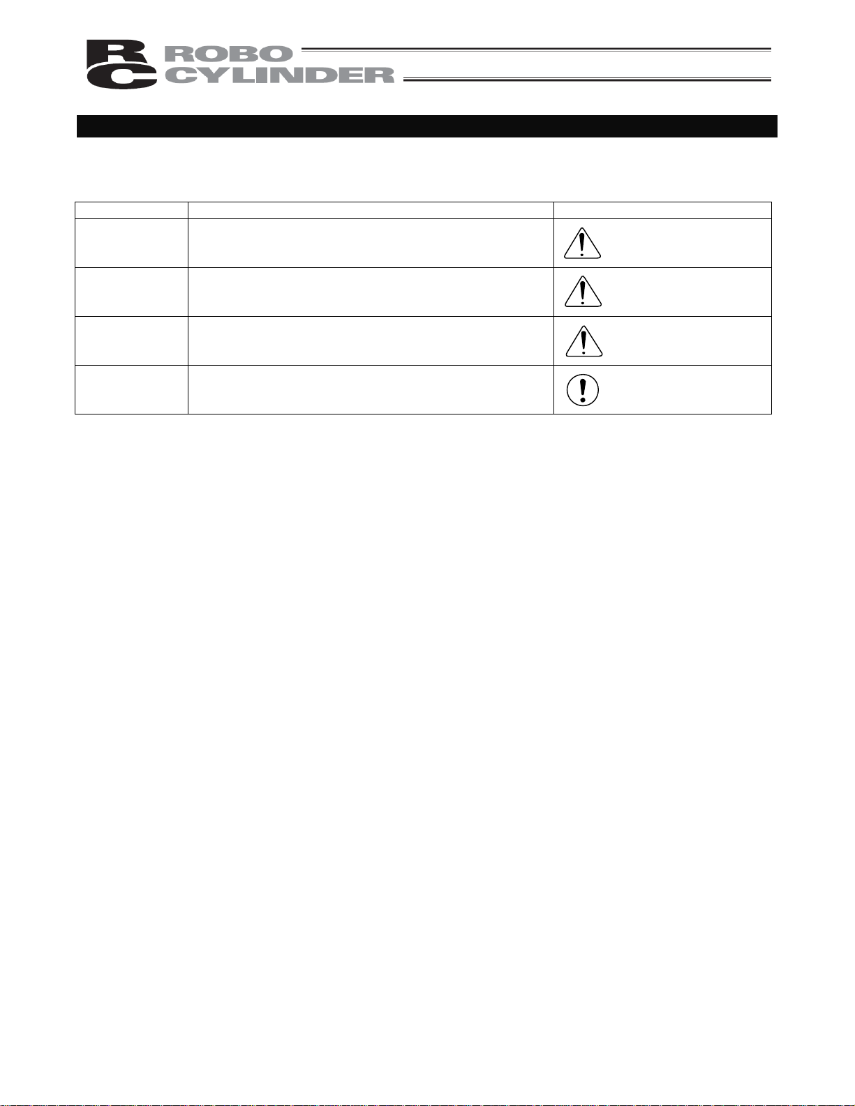
Indication of Cautionary Information
The operation manual for each model denotes safety precautions under “Danger,” “Warning,” “Caution” and
“Note,” as specified below.
Level Degree of danger/loss Symbol
Danger
Warning
Caution
Note
Failure to observe the instruction will result in an
imminent danger leading to death or serious injury.
Failure to observe the instruction may result in death or
serious injury.
Failure to observe the instruction may result in injury or
property damage.
The user should take heed of this information to ensure
the proper use of the product, although failure to do so
will not result in injury.
Danger
Warning
Caution
Note
Pre-7
Page 20

Pre-8
Page 21

1. Overview
1.1 Introduction
Thank you for purchasing the RCP2 controller. This manual explains the features and operating procedures of
the product.
If not used or handled properly, even a brilliant product cannot fully demonstrate its function or may cause an
unexpected breakdown or end its life prematurely. Please read this manual carefully and handle the product with
utmost care while ensuring its correct operation. Keep this manual in a convenient place so the relevant sections
can be referenced readily when necessary.
If you are also using any of IAI’s various actuators and/or optional PC software or teaching pendant, also refer to
the operation manual for each item.
1
Page 22
A
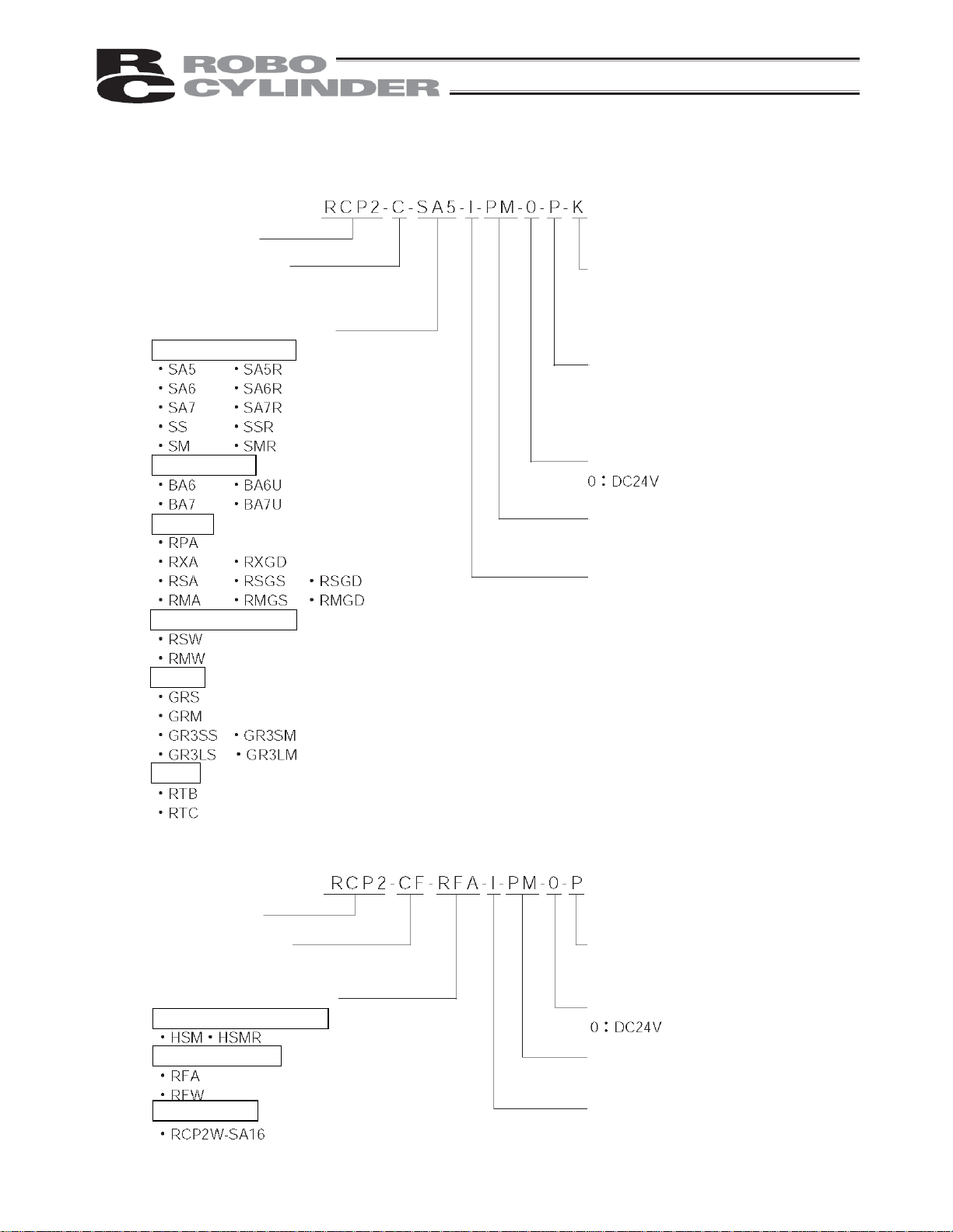
1.2 How to Read Model Number
Controller with a power-supply capacity of 2 A
<Series>
<Safety circuit type>
C: Built-in cutoff relay
CG: External cutoff relay
<Actuator type>
Slider, ball-screw type
Slider, belt type
Rod type
Rod, splash-proof type
<Absolute battery bracket>
Blank: Without bracket
K: With bracket
<I/O signal type>
Blank: NPN (sink type)
P: PNP (source type)
<Supply voltage>
<Motor type>
PM: Pulse motor
<Encoder type>
I: Incremental
: Absolute
Gripper
Rotary
Controller with a power-supply capacity of 6 A (Large-capacity type)
<Series>
<Safety circuit type>
CF: Built-in cutoff relay
<Actuator type>
High-speed ball-screw type
High-thrust rod type
Waterproof type
<I/O signal type>
Blank: NPN (sink type)
P: PNP (source type)
<Supply voltage>
<Motor type>
PM: Pulse motor
<Encoder type>
I: Incremental
2
Page 23

1.3 Handling of Secondary Batteries for the Absolute Specification
Observe the safety precautions specified below when handling the secondary batteries:
1. Never attempt to disassemble the batteries. Strong alkali battery fluid will damage the skin or clothes.
2. Never short the battery terminals (i.e. by allowing the positive and negative terminals to make direct contact).
Doing so may damage the equipment or cause burns due to the generatio n of heat.
3. Never throw the batteries into a fire, because it may cause them to explode. Also avoid immersing the
batteries in water, which can result in loss of battery function.
4. Do not solder the batteries directly. The safety valve inside the battery cap may be damaged, resulting in a
breakdown of the safety mechanism.
5. If the battery connector remains connected for a long time without a supply of power, a deep discharge may
occur and cause the battery fluid to leak or allow the battery performance or life to deteriorate/shorten
significantly. If the equipment is to be relocated or modified and the power will not be supplied for a prolonged
period, first disconnect the battery connector.
6. When disposing of used batteries, drop them into the collection box at an authorized recycle store or take
other appropriate steps.
* We have made every effort to ensure accuracy of the information provided in this manual. Should you find an
error, however, or if you have any comment, please contact IAI.
Keep this manual in a convenient place so it can be referen ce d re adily when necessary.
3
Page 24

1.4 Safety Precautions
Read the following information carefully and provide safety measures with due consideration.
This system product has been developed as a drive component for automated machinery and the like, and is
therefore designed not to generate excessive torque or speed beyond the levels needed to drive automated
equipment. However, the following instructions must be strictly observed to prevent an unexpected accident.
1. Do not handle this product in any manner not specified in this manual. If you have questions regarding any of
the information provided in this manual, please contact IAI.
2. Always use the specified genuine parts to wire your RCP2 controller and an actuator.
3. Do not enter the operating range of the machine while the machine is operating or is able to operate (the
controller power is ON). If the machine is used in a place accessible to other people, enclo se its operating
range using a safety cage, etc.
4. Always turn off the power supply to the controller before assembling/adjusting or maintaining/inspecting the
machine. During assembly/adjustment or maintenance/inspection, put a plate or other visible sign in a
conspicuous place indicating that work is in progress. The operator should ke ep the entire power cable
beside him or her to prevent another person from inadvertently plugging in the cable.
5. If two or more persons work together, set signaling methods so each person can confirm the safety of
other(s) during work. Especially when the work requires an axis or axes to be moved—with or without the
power and by motor drive or manual operation—the person moving each axis should always call out
beforehand to ensure safety.
6. If you have extended a cable or made other alteration to the standard wiring specification, thoroughly check
the wiring and ensure absence of problem before turning on the power, in order to prevent malfunction due to
miswiring.
4
Page 25

1.5 Warranty Period and Scope of Warranty
The RCP2 controller you have purchased passed IAI’s shipping inspection implemented under the strictest
standards. The unit is covered by the following warranty:
1. Warranty Period
The warranty period shall be one of the following periods, whichever ends first:
18 months after shipment from our factory
12 months after delivery to a specified location
2. Scope of Warranty
If an obvious manufacturing defect is found during the above period under an appropriate co ndition of use,
IAI will repair the defect free of charge. Note, however, that the following items are excluded from the scope
of warranty:
Aging such as natural discoloration of coating
Wear of a consumable part due to use
Noise or other sensory deviation that doesn’t affect the mechanical function
Defect caused by inappropriate handling or use by the user
Defect caused by inappropriate or erroneous maintenance/inspection
Defect caused by use of a part other than IAI’s genuine part
Defect caused by an alteration or other change not approved by IAI or its agent
Defect caused by an act of God, accident, fire, etc.
The warranty covers only the product as it has been delivered and shall not cover any losses arising in
connection with the delivered product. The defective product must be brought to our factory for repair.
Please read carefully the above conditions of warranty.
5
Page 26

2. Specifications
2.1 Basic Specifications
Specification item
RCP2-C-*** (Note) RCP2-CG-*** (Note)
Number of controlled axes 1 axis/unit
Internal Drive-Power Cutoff Relay
Type
External Drive-Power Cutoff
Relay Type
Supply voltage
Supply current 2 A max.
Control method Weak field-magnet vector control (patent pending)
Encoder resolution 800 P/rev
Positioning command
Position number Standard 16 points, maximum 64 points
Backup memory
PIO
LED indicators RDY (green), RUN (green), ALM (red)
Communication RS485 1 channel (terminated externally)
Encoder interface Incremental specification conforming to EIA RS-422A/423A
Forced release of electromagnetic
brake
Cable length
Isolation strength
Environment
Surrounding humidity 85%RH or less (non-condensing)
Storage temperature
Surrounding air
temperature
Surrounding
environment
24 VDC 10%
Position number specification
Direct specification
Position number data and parameters are saved in nonvolatile
memory.
Serial EEPROM can be rewritten 100,000 times.
10 dedicated inputs/10 dedicated outputs. Selectable from five
patterns.
Toggle switch on front panel of enclosure
Actuator cable: 20 m or less
PIO cable: 5 m or less
500 VDC, 10 M
0 to 40C
Not subject to corrosive gases.
-10 to 65C
Storage humidity 90%RH or less (non-condensing)
Vibration resistance
Protection class IP20
Weight 300 g or less
External dimensions 35 W x 178.5 H x 68.1 D mm
10 to 57 Hz in XYZ directions / Pulsating amplitude: 0.035 mm
(continuous), 0.075 mm (intermittent)
(Note) *** indicates the actuator type.
6
Page 27

2.1.1 Backup Batteries for the Absolute Specification
The absolute-specification controller uses secondary batteries (nickel metal hydride cells) to retain absolute
counter data in the FPGA (field-programmable gate array) after the power is cut off, and also to supply power to
the encoder’s drive circuit intermittently.
(1) Battery specification
Item Description
Classification Cylindrical sealed nickel metal hydride cell
Manufacturer Matsushita Battery Industrial
Model number AB-4
Nominal voltage 4.8 V (1.2 V x 4)
Rated capacity 1900 mAh (average capacity: 2050 mAh)
Average life Approx. 3 years
Charging time
Retention time after power cutoff
(2) Charging the batteries
Be sure to charge the batteries when the controller is powered up for the first time after delivery, and also after
new batteries have been installed.
The batteries are charged automatically while the power is being supplied to the controller, so keep the main
power on for at least 48 hours.
The actuator can be moved and the position table changed while the batteries are ch arging.
Additionally, charge the batteries for at least 48 hours after the power supply to the controller has been cut off for
a prolonged period (within the specified battery-retention time).
(3) Replacing the batteries
Batteries are consumable parts. Repeated charging and discharging of the batteries will diminish their initial
performance characteristics. If the retention time has decreased significantly, the batteries may have reached
the end of their useful life. If this should occur, replace the batteries.
The batteries should be replaced approximately three years after the controller is first connected to your
equipment, although the specific timing will vary depending on the surrounding air temperature and conditions of
charge/discharge.
The label on the battery unit shows a reference date, which is three years from the shipment date. Use this date
to determine when the batteries should be replaced.
Approx. 48 hours (at surrounding air temperature of 20C)
Approx. 250 hours (when the batteries are fully charged, at
surrounding air temperature of 20C)
Note: (1) Applying vibration, impact or other external force to the actuator or moving the slider, etc.,
while the power is off will erase the absolute data.
When the power is input again, the *ALM signal will turn OFF, the ALM lamp will illuminate
and the message “Absolute encoder error (2)” or “Absolute encoder error (3)” will be
displayed.
In this case, you must reset the alarm and perform a home return.
Never move the slider or rod while the power is off!
(2) It is recommended that the batteries be charged at normal temperature (+10 to +30C) to
prevent extreme temperatures from negatively affecting the charging efficiency.
Temperatures exceeding 45C may cause performance deterioration or the leakage of
battery fluid.
7
Page 28

2.1.2 Specifications of the Large-Capacity Type (RCP2-CF)
Specification item Internal Drive-Power Cutoff Relay Type
Model number RCP2-CF-***
Number of controlled axes 1 axis/unit
Supply voltage
Supply current 6 A max.
Control method Weak field-magnet vector control (patent pending)
Encoder resolution 800 P/rev
Positioning command
Position number Standard 16 points, maximum 64 points
Backup memory
PIO
LED indicators RDY (green), RUN (green), ALM (red)
Communication RS485 1 channel (terminated externally)
Encoder interface Incremental specification conforming to EIA RS-422A/423A
Forced release of electromagnetic
brake
Cable length
24 VDC 10%
Position number specification
Direct specification
Position number data and parameters are saved in nonvolatile
memory.
Serial EEPROM can be rewritten 100,000 times.
10 dedicated inputs/10 dedicated outputs. Selectable from five
patterns.
Toggle switch on front panel of enclosure
Actuator cable: 20 m or less
PIO cable: 5 m or less
Isolation strength
Environment
Surrounding humidity 85%RH or less (non-condensing)
Storage temperature
Storage humidity 90%RH or less (non-condensing)
Vibration resistance
Protection class IP20
Weight 300 g or less
External dimensions 35 W x 180 H x 71.6 D mm
8
Surrounding air
temperature
Surrounding
environment
500 VDC, 10 M
0 to 40C
Not subject to corrosive gases.
-10 to 65C
10 to 57 Hz in XYZ directions / Pulsating amplitude: 0.035 mm
(continuous), 0.075 mm (intermittent)
Page 29
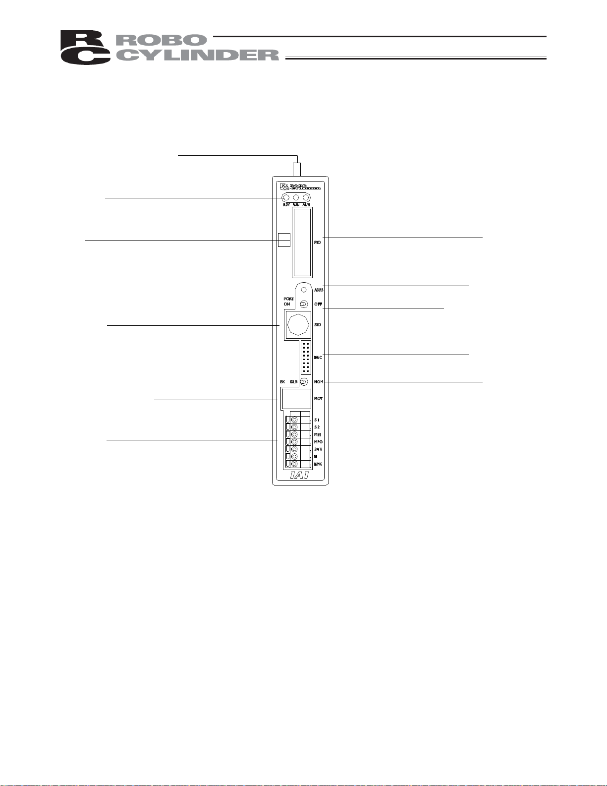
2.2 Name and Function of Each Part of the Controller
2.2.1 Names
[2] Status indicator LEDs
RDY (green) RUN (green) ALM (red)
[3] PIO pattern number label
[4] Teaching pendant/
PC connector
[6] Power/emergency-stop
terminal block
2.2.2 Functions
[1] Battery connector
A connector for the absolute data retention batteries.
[2] Status indicator LEDs
RDY: When lit, this LED indicates that 24V power is supplied and the CPU is operating.
RUN: This LED indicates the servo status. Lit = Servo is ON, Unlit = Servo is OFF.
ALM: When lit, this LED indicates that an alarm is present, or an emergency stop has been actuated or the
motor drive power is cut off.
With the absolute specification controller, a blinking ALM LED indicates that the battery voltage has
dropped to approx. 4.1 V or below when the power is cut off.
[3] PIO pattern number label (IOPN)
Write down the PIO pattern selected in parameter No. 25 on this label.
(This will facilitate maintenance if multiple controllers are used in different patterns.)
[4] Teaching pendant/PC connector (SIO)
A connector for the dedicated teaching pendant or PC communication cable.
This cable is also used to link two or more controllers to enable serial communication among them.
[1] Battery connector
(absolute specification)
[5] Motor connector
[7] I/O signal connector
[8] Address switch
[9] PORT switch
[10] Encoder connector
[11] Brake release switch
9
Page 30

[5] Motor connector (MOT)
A connector for the actuator’s motor power cable.
[6] Power/emergency-stop terminal block
[Built-in cutoff relay type RCP2-C, RCP2-CF]
Provide a contact output for the emergency-stop button on the teaching pendant.
S1, S2
Port switch ON = Emergency-stop button output (Contact B)
Port switch OFF = ON in normal conditions of use (Emergency-stop button output is
disabled)
Provide a contact for cutting off the motor drive power. MPI and MPO represent the
MPI, MPO
input side and output side of the motor power supply, respectively. (Short these
terminals using a jumper wire if not used. The controller is shipped with MPI and
MPO shorted.)
24V Positive side of the 24-V power supply
N Negative side of the 24-V power supply
EMG Emergency-stop input
[External cutoff relay type RCP2-CG]
Provide a contact output for the emergency-stop button on the teaching pendant.
S1, S2
Port switch ON = Emergency-stop button output (Contact B)
Port switch OFF = ON in normal conditions of use (Emergency-stop button output is
disabled)
Provide a contact for cutting off the motor drive power. MPI and MPO represent the
MPI, MPO
input side and output side of the motor power supply, respectively. (Connect an
external safety circuit.)
24V Positive side of the 24-V power supply
N Negative side of the 24-V power supply
FG FG of the 24-V power supply
[7] I/O signal connector (PIO)
A PIO cable connector to the host controller (PLC, etc.).
[8] Address switch (ADRS)
A switch for setting the address for the controller axis.
If two or more controllers are connected in the serial communication mode, do not specify duplicate controller
addresses.
Setting range: 0 to F (A maximum of 16 controllers can be connected.)
[9] PORT switch (PORT)
A switch for enabling/disabling the serial communication port.
Set this switch to ON when connecting the controller to a teaching pendant or PC. Set it to OFF if no teaching
pendant or PC is connected.
* If this switch is turned ON without connecting a teaching pendant or PC, an emergency stop will be actuated.
[10] Encoder connector (ENC)
A connector for the actuator’s encoder/brake cables.
[11] Brake release switch (BK)
A switch for forcibly releasing the brake when the actuator is used with a brake option.
RLS: Brake is forcibly released
NOM: Normal setting (Brake is controlled by the controller)
10
Page 31

2.3 External Dimensions
2.3.1 Standard Specification (RCP2-***-I )
An external view and dimensions of the product are shown below.
(Mounting dimension)
11
Page 32

2.3.2 Absolute Specification with Battery Bracket (RCP2-***-A- -K)
(Mounting dimension)
*Weight: 660 g
12
Page 33

Absolute Specification without Battery Bracket
(RCP2-***-A- )
(Mounting dimension)
*Weight: 460 g
13
Page 34

2.3.3 Large-Capacity Type (RCP2-CF-***)
Built-in
radiating fan
*Weight: 250 g
(Mounting dimension)
14
Page 35

3. Installation and Noise Elimination
Pay due attention to the installation environment of the controller.
3.1 Installation Environment
(1) When installing and wiring the controller, do not block the cooling ventilation holes. (Insufficient ventilation
will not only prevent the controller from demonstrating its full performance, but it may also cause
breakdown.)
(2) Prevent foreign matter from entering the controller through the ventilation holes. Since the enclosure of the
controller is not dustproof or waterproof (oilproof), avoid using the controller in a place subject to significant
dust, oil mist or splashes of cutting fluid.
(3) Do not expose the controller to direct sunlight or radiating heat from a large heat source such as a heat
treatment furnace.
(4) Use the controller in an environment free from corrosive or inflammable gases, under a temperature of 0 to
40C and humidity of 85% or less (non-condensing).
(5) Use the controller in an environment where it will not receive any external vibration or shock.
(6) Prevent electrical noise from entering the controller or its cables.
3.2 Power Supply
The power supply specification is 24 VDC 10%.
(Supply current: 2 A max.)
3.3 Noise Elimination and Grounding
This section explains how to eliminate noise in the use of the controller.
(1) Wiring and power supply
[1] Provide a dedicated class D grounding using a wire with a size of 2.0 to 5.5 mm2 or larger.
Controller
Other
equipment
Controller
Use a cable of a
maximum possible
size and keep the
wiring length at a
minimum.
Metal frame
Class D grounding Good Avoid this grounding method.
Other
equipment
15
Page 36

[2] Precautions regarding wiring method
Use a twisted cable for connection to the 24-VDC external power supply.
Separate the controller cables from high-power lines such as a cable connecting to a power circuit. (Do not
bundle together the controller cables with high-power lines or place them in the same cable duct.)
When extending the supplied motor cable or encoder cable, consult IAI’s Technical Support.
(2) Noise sources and elimination
Among the numerous noise sources, solenoid valves, magnet switches and relays are of particular concern
when building a system. Noise from these sources can be eliminated by implementing the measures specified
below.
[1] AC solenoid valves, magnet switches and relays
Measure: Install a surge absorber in parallel with the coil.
[2] DC solenoid valves, magnet switches and relays
Measure: Install a diode in parallel with the coil. Determine the diode capacity in accordance with the load
capacity.
Point
Install a surge absorber to each coil over a minimum wiring length.
Installing a surge absorber to the terminal block or other part will
be less effective because of a longer distance from the coil.
In a DC circuit, connecting a diode in reverse polarity will damage the
diode, internal parts of the controller and/or DC power supply, so exercise
due caution.
16
Page 37

3.4 Heat Radiation and Inst allation
Design the control panel size, controller layout and cooling method in such a way that the temperature around
the controller will not exceed 40C.
Install the controller vertically on a wall, as shown below. Since cooling is provided by way of natural convection,
always observe this installation direction and provide a minimum clearance of 50 mm above and below the
controller to ensure sufficient natural airflows.
When installing multiple controllers side by side, providing a ventilation fan or fans above the controllers will help
maintain a uniform temperature around the controllers.
Keep the front panel of the controller away from the wall (enclosure) by at least 95 mm.
Regardless of whether your system consists of a single controller or multiple controllers, provide sufficient
clearances around each controller so that it can be installed/removed easily.
In the case of the large-capacity type, extra space is required to release the exhaust heat from the radiating fan.
Therefore, provide a clearance of 15 mm or more for this controller type.
Fan
50 mm or more
50 mm or more
95 mm
or more
Airflow
17
Page 38

4. Wiring
4.1 Internal Drive-Power Cutoff Relay Type (RCP2-C, RCP2-CF)
4.1.1 Configuration
Standard teaching pendant
<RCA-T>
Cable length: 5 m
<RCB-105-2> Cable length: 2 m
<RCB-105-5> Cable length: 5 m
External unit
Optional
PC
PC software
<RCB-101-MW>
Optional
Optional
External EMG switch
Input power supply
24V
24 VDC 0
Supplied flat
cable
Cable length: 2 m
Host system <PLC>
* If the PLC is not used,
disable the servo ON
input and pause input
using the applicable
parameters.
ROBO cylinder
Cable length: 5 m
Optional
Do not connect or disconnect
the connectors while the
S1
S2
MPI
MPO
24V
N
EMG
power is on, except for the
communication port
connector (SIO). To connect
or disconnect the SIO, do so
after turning off the PORT
switch. Failure to do so may
result in breakdown.
Note: Connect one end of the EMG switch to the 24-V output of the input power supply and the
other end to the S1 terminal. Also short the S2 and EMG terminals using a jumper wire.
18
Page 39

4.1.2 External Connection Diagram
An example of standard wiring is shown below.
(Note) The encoder cable shown in the example is the standard cable for the controller with the maximum
current of 2 A.
As for the robot cable or the cable for the large-capacity type, refer to 4.4.2, “Encoder Extension Cable.”
Connected to teaching
pendant or PC
External EMG switch
Input power supply
24 VDC 24V
0V
FG
Host system
flat cable
Refer to 4.3, “Connecting the
I/O Cables,” for the connection
of I/O signals.
Terminal block
Controller
(PORT switch)
Blue
Black
White
Red
Black
Green
Yellow
Orange (black 2)
Orange (red 2)
Yellow (black 1)
Yellow (red 1)
White (black 1)
White (red 1)
Light blue (black 1)
Light blue (red 1)
Brake release switch
Tighten together with the
mounting screw.
Actuator
Motor
Encoder
Holding
brake
19
Page 40

4.1.3 Wiring the Power Supply/Emergency-Stop Switch
(1) Wiring the power supply
Input power supply
24 VDC
(2 A max. per controller)
24V
0V
FG
To connect multiple controllers, provide a relay terminal block.
Use a power cable satisfying the following specifications:
Item Specification
Applicable wire length
Single wire: 1.0 / Stranded: 0.8 mm
Stripped wire length 10 mm
Temperature rating of
insulating sheath
60C or above
* Use a flathead screwdriver with a blade tip of approx. 2.6 mm to push in the wire.
Notes on wiring the absolute-specification controller
[1] When connecting a relay to the 24-V line, be sure to install it on the positive side of the 24-V power su pply.
S1
S2
MPI
MPO
24V
N
EMG
2
, AWG size 18 (copper wire)
Keep the negative side of the 24-V power supply connected without cutting it off with a relay.
If a relay is installed on both the positive and negative sides, an ABS error may generate.
[2] Connect a surge killer to the relay contact.
Chattering of the relay may have negative effect on the controller.
Connect a surge killer to prevent malfunction.
Surge killer
Recommended product: Spark Killer by Okaya Electric
Industries
Model number: CR-50500
Capacitance: 0.5 F 20%
Resistance: 50 (1/2W) 30%
RCP2ABS
24V+
N
24VPS
AC
Relay
Do not install a relay on the negative side.
20
Page 41

(2) Wiring the emergency-stop switch
In many cases multiple controllers are used in a single system.
To provide an emergency-stop function for the entire system, the controller circuit is designed in su ch a way that
a single EMG switch is able to actuate an emergency stop in all connected controllers.
[Internal emergency-stop circuit]
Teaching pendant
Input power supply
(C: 2 A max.)
(CF: 6 A max.)
24V
0V
EMG signal
S1
S2
MPI
MPO
24V
N
EMG
ON
OFF
PORT
switch
Controller
power supply
Relay
Motor
power
supply
(Note) The current consumption of the internal relay is 10 mA or less.
[Example of recommended circuit]
(Reference)
EMG switch on teaching pendant 30 VDC 3 A
PORT switch 24 VDC 0.1 A
RCP2 controller
24V
EMG switch on
teaching pendant
External EMG
reset switch
External EMG
circuit
S1
RCP2 controller
CR
(3 A)
PORT switch
ON
OFF
(0.1 A)
Cutoff voltage Cutoff current
S2
N
0V
CR
Coil current:
0.1 A or less
MPI
MPO
CR
24V
EMG
Relay
N
(Note) To cut off the motor drive power supply in conformance with safety category 2, connect 24V to the EMG
terminal and a contactor or other contact device to the MPI/MPO terminals. (Refer to 4.2.3; rush current:
8 A.)
21
Page 42

Representative connection examples are explained below.
Connecting the teaching pendant directly to the controller (Parallel connection with the PLC)
[1] Connecting multiple controllers (8 units or less) using a single power supply
Short the MPI and MPO terminals using a jumper wire. (The controller is shipped with these terminals
shorted.)
Connect one end of the EMG signal to the 24-V output of the input power supply and the other end to the S1
terminal.
Then, provide connections by sequentially connecting the S2 terminal of controller 1 to the S1 terminal of
controller 2, the S2 terminal of controller 2 to the S1 terminal of controller 3, and so on, and connect the S2
terminal on the last controller to the EMG terminals on all controllers.
Use a relay terminal block for connection to the EMG terminals.
(Note) Do not connect two or more wires to one terminal.
22
Page 43

24V
EMG signal
[Controller 1]
Teaching pendant
S1 S2
ON
MPI
MPO
24V
EMG
[Controller 2]
Teaching pendant
S1 S2
MPI
MPO
24V
EMG
[Controller 3]
Teaching pendant
S1 S2
MPI
MPO
24V
EMG
[Controller 4]
Teaching pendant
S1 S2
OFF
PORT switch
N
Relay
ON
OFF
PORT switch
N
Relay
ON
OFF
PORT switch
N
Relay
0V
PORT switch
ON
OFF
N
Relay
MPI
MPO
24V
EMG
23
Page 44

[2] Using a power supply other than the input power supply
(Note) Since the controller’s PORT switch has a cutoff capacity of 0.1 A, use an auxiliary relay with a coil
current of 0.1 A or less and connect a diode for coil surge absorption.
control
C 0V
power
P 24V
EMG signal
P 0V
CR
[Controller 1]
Teaching pendant
S1 S2
ON
MPI
MPO
24V
N
EMG
OFF
PORT switch
Relay
[Controller 2]
Teaching pendant
S1 S2
ON
MPI
MPO
24V
N
EMG
OFF
PORT switch
Relay
[Controller 3]
Teaching pendant
S1
MPI
MPO
24V
N
EMG
ON
OFF
PORT switch
Relay
S2
C 24V
CR
24
Page 45

[3] Enabling the EMG switch on the teaching pendant for the connected axis or axes only
24V
EMG signal
CR
[Controller 1]
Teaching pendant
S1
MPI
MPO
24V
EMG
PORT switch
[Controller 2]
Teaching pendant
S1
MPI
MPO
24V
EMG
PORT switch
[Controller 3]
CR
S2
ON
OFF
N
Relay
S2
ON
OFF
N
Relay
Teaching pendant
S1
S2
MPI
MPO
24V
EMG
PORT switch
ON
OFF
N
Relay
0V
25
Page 46

Connecting the teaching pendant to a SIO converter (Serial connection with the PLC)
Configure the contact circuit for the EMG switch on the teaching pendant using EMG1/EMG2 on the
power/emergency-stop terminal block on the SIO converter. (S1/S2 on the controller’s terminal block are
not used.)
24V
SIO converter
0V
EMG signal
Teaching pendant
EMG2
EMG1
CR
ON
OFF
PORT switch
MPI
MPO
24V
EMG
MPI
MPO
24V
EMG
[Controller 1]
Relay
[Controller 2]
Relay
[Controller 3]
N
N
CR
MPI
MPO
24V
EMG
Relay
N
26
Page 47

4.2 External Drive-Power Cutoff Relay Type (RCP2-CG)
4.2.1 Configuration
<RCB-105-2> Cable length: 2 m
<RCB-105-5> Cable length: 5 m
External unit
<RCB-101-MW>
Standard teaching pendant
<RCA-T>
Optional
Cable length: 5 m
Optional
PC
PC software
Optional
Input power supply
24V
24 VDC 0
FG
Safety relay
contactor for
motor drivepower cutoff
circuit
Supplied flat
cable
Cable length: 2 m
S1
S2
MPI
MPO
24V
N
FG
Host system <PLC>
* If the PLC is not used,
disable the servo ON
input and pause input
using the applicable
parameters.
ROBO cylinder
Cable length: 5 m
Optional
Do not connect or disconnect
the connectors while the
power is on, except for the
communication port
connector (SIO). To connect
or disconnect the SIO, do so
after turning off the PORT
switch. Failure to do so may
result in breakdown.
27
Page 48

4.2.2 External Connection Diagram
An example of standard wiring is shown below.
(Note) The encoder cable shown in the example is the standard cable.
As for the robot cable, refer to 4.4.2, “Encoder Extension Cable.”
Connected to teaching
pendant or PC
Input power supply
24V
24 VDC 0V
FG
Host system
Refer to 4.3, “Connecting
the I/O Cables,” for the
connection of I/O signals.
Motor drivepower cutoff
circuit
flat cable
Controller
(PORT switch)
Terminal block
Blue
Black
White
Red
Black
Green
Yellow
Orange (black 2)
Orange (red 2)
Yellow (black 1)
Yellow (red 1)
White (black 1)
White (red 1)
Light blue
(black 1)
Light blue
(red 1)
Brake release switch
Actuator
Motor
Encoder
Holding
brake
28
Page 49

4.2.3 Wiring the Power Supply/Motor Power Cutoff Relay
(1) Wiring the power supply
Input power supply
24 VDC
(2 A max. per controller)
24V
0V
FG
To connect multiple controllers, provide a relay terminal block.
Use a power cable satisfying the following specifications:
Item Specification
Applicable wire length
Single wire: 1.0 / Stranded: 0.8 mm
Stripped wire length 10 mm
Temperature rating of
insulating sheath
60C or above
* Use a flathead screwdriver with a blade tip of approx. 2.6 mm to push in the wire.
Notes on wiring the absolute-specification controller
[1] When connecting a relay to the 24-V line, be sure to install it on the positive side of the 24-V power su pply.
S1
S2
MPI
MPO
24V
N
FG
2
, AWG size 18 (copper wire)
Keep the negative side of the 24-V power supply connected without cutting it off with a relay.
If a relay is installed on both the positive and negative sides, an ABS error may generate.
[2] Connect a surge killer to the relay contact.
Chattering of the relay may have negative effect on the controller.
Connect a surge killer to prevent malfunction.
Surge killer
Recommended product: Spark Killer by Okaya Electric
Industries
Model number: CR-50500
Capacitance: 0.5 F 20%
Resistance: 50 (1/2W) 30%
RCP2ABS
24V+
N
Relay
24VPS
AC
Do not install a relay on the negative side.
29
Page 50

(2) Wiring the motor power cutoff relay
Explained below is a safety circuit conforming to safety category 2.
The user is responsible for implementing additional safety measures in the actual circuit configuration, such as
providing double contactor contacts to prevent fusing.
The circuit illustrated below is for reference purposes only.
The input side of the motor drive power supply is connected to the MPI terminal, while the output side is
connected to the MPO terminal. Connect a contactor or other contact device to these terminals.
(Note) The rush current must be 8 A or less. The rated current is 2 A.
The contact for the EMG switch on the teaching pendant is provided by the S1/S2 terminals.
(Note) When connecting the teaching pendant to a SIO converter, the contact for the EMG switch on the
teaching pendant is provided by the EMG1/EMG2 terminals on the SIO converter.
[Example of basic circuit]
0V
24V
External EMG
reset switch
External EMG
circuit
S1
MC
MC
Coil current:
0.1 A or less
MC
(Rush-in current: 8 A,
rated current: 2 A)
(MAX. 2 A)
S2
MPI
MPO
24V
N
FG
Teaching pendant
EMG switch
(3 A)
ON
OFF
PORT switch
(0.1 A)
Motor power
supply
Controller
power supply
RCP2 controller
30
Page 51

[Connection example of a multiple-axis configuration]
Input power supply
24V
0V
FG
EMG signal
S33 S34
S11
Phoenix contact (PSR-SCP-24UC-/ESA2/4X1/1X2/B)
A1
Safety relay unit
A2
Connect to 24-V terminal
Connect to N terminal
Connect to FG terminal
[Controller 1] [Controller 2] [Controller 3]
S1
S2
MPI
MPO
24V
N
FG
S1
S2
MPI
MPO
24V
N
FG
Contactor
External reset switch
S12
13
23
33
24
14
34
S1
S2
MPI
MPO
24V
N
FG
31
Page 52

4.3 Connecting the I/O Cables
PIO pattern 0 [Conventional]
Host system <PLC> end
Command position 1
Command position 2
Command position 4
Command position 8
Output side
Completed position 1
Completed position 2
Completed position 4
Completed position 8
Input side
+24 [V]
0 [V]
Start
Pause
Position complete
Home return
completion
Zone output
Alarm
Emergency stop
Upper
stage
Lower
stage
Brown 1
Red 1
Orange 1
Yellow 1
Green 1
Blue 1
Purple 1
Gray 1
White 1
Black 1
Brown 2
Red 2
Orange 2
Yellow 2
Green 2
Blue 2
Purple 2
Gray 2
White 2
Black 2
Brown 3
Red 3
Orange 3
Yellow 3
Green 3
Blue 3
Note: The factory-set PIO pattern is [Conventional].
The pause signal may be disabled using parameter No. 15.
Blue 3
Brown 1
Controller end
PIO (signal abbreviation)
1A P24
2A N
3A CSTR
4A PC1
5A PC2
6A PC4
7A PC8
8A
9A
10A *STP
11A
12A
13A
1B
2B
3B PM1
4B PM2
5B PM4
6B PM8
7B PEND
8B HEND
9B ZONE
10B *ALM
11B *EMGS Available on “RCP2-C.” Not used on “RCP2-CG.”
12B
13B
(Note) *STP, *ALM and *EMGS are based on the negative logic.
Lower stage
Upper stage
13A
1A
13B
1B
Note: When performing a continuity check of the flat cable, pay due attention not to expand the
female pins in the connector. It may cause contact failure and disable normal operation of the
controller.
32
Page 53

PIO pattern 1 [Standard]
Host system <PLC> end
Command position 1
Command position 2
Command position 4
Command position 8
Output side
Completed position 1
Completed position 2
Completed position 4
Completed position 8
Input side
+24 [V]
0 [V]
Pause
Start
Home return
Servo ON
Reset
Zone output
Moving
Position complete
Home return
completion
Emergency stop
Ready
Alarm
Upper
stage
Lower
stage
Brown 1
Red 1
Orange 1
Yellow 1
Green 1
Blue 1
Purple 1
Gray 1
White 1
Black 1
Brown 2
Red 2
Orange 2
Yellow 2
Green 2
Blue 2
Purple 2
Gray 2
White 2
Black 2
Brown 3
Red 3
Orange 3
Yellow 3
Green 3
Blue 3
Controller end
PIO (signal abbreviation)
1A P24
2A N
3A PC1
4A PC2
5A PC4
6A PC8
7A
8A *STP
9A CSTR
10A HOME
11A SON
12A RES
13A
1B
2B
3B PM1
4B PM2
5B PM4
6B PM8
7B ZONE
8B MOVE
9B PEND
10B HEND
11B *EMGS Available on “RCP2-C.” Not used on “RCP2-CG.”
12B SRDY
13B *ALM
(Note) *STP, *ALM and *EMGS are based on the negative logic.
Note: The factory-set PIO pattern is [Conventional], so change the value in parameter No. 25 to “1.”
To enable the servo ON signal, be sure to set parameter No. 21 to “0.” The pause signal may
be disabled using parameter No. 15.
Blue 3
Lower stage
Upper stage
13A
1A
13B
1B
Brown 1
Note: When performing a continuity check of the flat cable, pay due attention not to expand the
female pins in the connector. It may cause contact failure and disable normal operation of the
controller.
33
Page 54

PIO pattern 2 [64-point positioning]
Host system <PLC> end
Command position 1
Command position 2
Command position 4
Command position 8
Command position 16
Command position 32
Output side
Completed position 1
Completed position 2
Completed position 4
Completed position 8
Completed position 16
Completed position 32
Input side
+24 [V]
0 [V]
Start
Home return
Pause
Reset
Position complete
Home return
completion
Emergency stop
Moving
Alarm
Upper
stage
Lower
stage
Brown 1
Red 1
Orange 1
Yellow 1
Green 1
Blue 1
Purple 1
Gray 1
White 1
Black 1
Brown 2
Red 2
Orange 2
Yellow 2
Green 2
Blue 2
Purple 2
Gray 2
White 2
Black 2
Brown 3
Red 3
Orange 3
Yellow 3
Green 3
Blue 3
Controller end
PIO (signal abbreviation)
1A P24
2A N
3A PC1
4A PC2
5A PC4
6A PC8
7A PC16
8A PC32
9A CSTR
10A HOME
11A *STP
12A RES
13A
1B
2B
3B PM1
4B PM2
5B PM4
6B PM8
7B PM16
8B PM32
9B PEND
10B HEND
11B *EMGS Available on “RCP2-C.” Not used on “RCP2-CG.”
12B MOVE
13B *ALM
(Note) *STP, *ALM and *EMGS are based on the negative logic.
Note: The factory-set PIO pattern is [Conventional], so change the value in parameter No. 25 to “2.”
The pause signal may be disabled using parameter No. 15.
Blue 3
Lower stage
Upper stage
13A
1A
13B
1B
Brown 1
Note: When performing a continuity check of the flat cable, pay due attention not to expand the
female pins in the connector. It may cause contact failure and disable normal operation of the
controller.
34
Page 55

PIO pattern 3 [2 zone output signals]
Host system <PLC> end
Command position 1
Command position 2
Command position 4
Command position 8
Output side
Completed position 1
Completed position 2
Completed position 4
Completed position 8
Input side
+24 [V]
0 [V]
Pause
Start
Home return
Servo ON
Reset
Zone output 1
Zone output 2
Position complete
Home return
completion
Emergency stop
Ready
Alarm
Upper
stage
Lower
stage
Brown 1
Red 1
Orange 1
Yellow 1
Green 1
Blue 1
Purple 1
Gray 1
White 1
Black 1
Brown 2
Red 2
Orange 2
Yellow 2
Green 2
Blue 2
Purple 2
Gray 2
White 2
Black 2
Brown 3
Red 3
Orange 3
Yellow 3
Green 3
Blue 3
Controller end
PIO (signal abbreviation)
1A P24
2A N
3A PC1
4A PC2
5A PC4
6A PC8
7A
8A *STP
9A CSTR
10A HOME
11A SON
12A RES
13A
1B
2B
3B PM1
4B PM2
5B PM4
6B PM8
7B ZONE1
8B ZONE2
9B PEND
10B HEND
11B *EMGS Available on “RCP2-C.” Not used on “RCP2-CG.”
12B SRDY
13B *ALM
(Note) *STP, *ALM and *EMGS are based on the negative logic.
Note: The factory-set PIO pattern is [Conventional], so change the value in parameter No. 25 to “3.”
To enable the servo ON signal, be sure to set parameter No. 21 to “0.” The pause signal may
be disabled using parameter No. 15.
Blue 3
Lower stage
Brown 1
Upper stage
13A
1A
13B
1B
Note: When performing a continuity check of the flat cable, pay due attention not to expand the
female pins in the connector. It may cause contact failure and disable normal operation of the
controller.
35
Page 56

PIO pattern 4 [Teaching]
Host system <PLC> end
Command position 1
Command position 2
Command position 4
Command position 8
Output side
Start/Position write
Completed position 1
Completed position 2
Completed position 4
Completed position 8
Input side
+24 [V]
0 [V]
Operation mode
Pause/+Jog
Home return
Servo ON
Reset/–Jog
Current operation
Position complete/
Write completion
Emergency stop
mode
Moving
Home return
completion
Ready
Alarm
Upper
stage
Lower
stage
Brown 1
Red 1
Orange 1
Yellow 1
Green 1
Blue 1
Purple 1
Gray 1
White 1
Black 1
Brown 2
Red 2
Orange 2
Yellow 2
Green 2
Blue 2
Purple 2
Gray 2
White 2
Black 2
Brown 3
Red 3
Orange 3
Yellow 3
Green 3
Blue 3
Controller end
PIO (signal abbreviation)
1A P24
2A N
3A PC1
4A PC2
5A PC4
6A PC8
7A MODE
8A *STP/JOG +
9A CSTR/PWRT
10A HOME
11A SON
12A RES/JOG 13A
1B
2B
3B PM1
4B PM2
5B PM4
6B PM8
7B MODES
8B MOVE
9B PEND/WEND
10B HEND
11B *EMGS Available on “RCP2-C.” Not used on “RCP2-CG.”
12B SRDY
13B *ALM
(Note) *STP, *ALM and *EMGS are based on the negative logic.
Note: The factory-set PIO pattern is [Conventional], so change the value in parameter No. 25 to “4.”
To enable the servo ON signal, be sure to set parameter No. 21 to “0.”
Be sure to enable the pause signal using parameter No. 15 (by setting the parameter to “0”)
(the pause signal is enabled at the factory). The system cannot switch to the teaching mode if
the pause signal is disabled (i.e., the above parameter is set to “1”).
Blue 3
Lower stage
Upper stage
13A
1A
13B
1B
Brown 1
Note: When performing a continuity check of the flat cable, pay due attention not to expand the
female pins in the connector. It may cause contact failure and disable normal operation of the
controller.
36
Page 57

PIO pattern 5 [4 points] (air cylinder)
Host system <PLC> end
Intermediate point
Intermediate point
Output side
Rear end complete
Front end complete
Intermediate point
Intermediate point
Input side
+24 [V]
0 [V]
Rear end move
Front end move
1 move
2 move
Pause
Reset
1 complete
2 complete
Zone output
Position complete
Home return
completion
Emergency stop
Alarm
Upper
stage
Lower
stage
Brown 1
Red 1
Orange 1
Yellow 1
Green 1
Blue 1
Purple 1
Gray 1
White 1
Black 1
Brown 2
Red 2
Orange 2
Yellow 2
Green 2
Blue 2
Purple 2
Gray 2
White 2
Black 2
Brown 3
Red 3
Orange 3
Yellow 3
Green 3
Blue 3
Controller end
PIO (signal abbreviation)
1A P24
2A N
3A ST0
4A ST1
5A ST2
6A ST3
7A
8A *STP
9A
10A
11A
12A RES
13A
1B
2B
3B PE0
4B PE1
5B PE2
6B PE3
7B ZONE
8B
9B PEND
10B HEND
11B *EMGS Available on “RCP2-C.” Not used on “RCP2-CG.”
12B
13B *ALM
(Note) *STP, *ALM and *EMGS are based on the negative logic.
Note: The factory-set PIO pattern is [Conventional], so change the value in parameter No. 25 to “5.”
The pause signal may be disabled using parameter No. 15.
Blue 3
Lower stage
Upper stage
13A
1A
13B
1B
Brown 1
Note: When performing a continuity check of the flat cable, pay due attention not to expand the
female pins in the connector. It may cause contact failure and disable normal operation of the
controller.
37
Page 58

4.4 Connecting the Actuator
4.4.1 Motor Extension Cable
Connect the motor extension cable to the MOT connector.
Signal table for the controller-end connector (CN2)
Pin No. Signal Wire color Description
A1
A
A2 VMM Gray Motor power line
A3
B
B1 A Yellow Motor drive line (phase +A)
B2 VMM Pink Motor power line
B3 B
Controller end
CN2 pin assignments
1 3
2
A
B
Cable color Pin No.
Orange
Gray
White
Yellow
Pink
Yellow (Black 1)
CN2
Signal
abbreviation
A
VMM
B
A
VMM
B
Housing: 1-1318119-3 (AMP) Housing: SLP-06V (J.S.T. Mfg.)
Receptacle contact: 1318107-1 Socket contact: BSF-21T-P1.4
Orange Motor drive line (phase –A)
White Motor drive line (phase –B)
Yellow
(Black 1)
CN2
A1
A2
A3
B1
B2
B3
Motor drive line (phase +B)
CB-RCP2-MA * * *
Actuator end
CN1 pin assignments
4
CN1
Pin No. Cable color
1
CN1
Signal
abbreviation
1
2
3
4
5
6
A
VMM
A
B
VMM
B
6
3
Yellow
Gray
Orange
Yellow (Black 1)
Pink
White
38
Page 59

4.4.2 Encoder Extension Cable [Standard controller (2 A)]
Connect the encoder extension cable to the ENC connector.
Signal table for the controller-end connector (CN2)
Pin No. Signal abbreviation Description
1 F.G Shielded wire
2 - (Not used)
3 - (Not used)
4 - (Not used)
5 GND Encoder power output
6 5V
7 VPS Encoder control signal output
8 - (Reserved)
9
EN B
10 EN B
11
EN A
12 EN A
13 BK – Negative side of the brake power supply
14 BK + Positive side of the brake power supply
15 - (Reserved)
16 - (Reserved)
Cable colors and pin assignments for units shipped in and after August 2004 (supporting the absolute
specification)
Controller end
CN2 pin assignments
1
2
CN2
15
16
Housing: PHDR-16VS (J.S.T. Mfg.)
Contact: SPHD-001T-P0.5
Cable color
Robot cable
-
-
Purple
White (with purple)
Blue
White (with blue)
Yellow
White (with yellow)
-
Green
Red
White (with red)
-
-
-
Ground
Standard cable
CN2
-
-
Red
Gray
Brown
Green
Purple
Pink
-
Yellow
Orange
Blue
-
-
-
Ground
Standard cable
Robot cable
Signal
abbreviation
(Reserved)
(Reserved)
BK +
BK –
ENA
ENA
ENB
ENB
(Reserved)
VPS
5V
GND
-
-
-
F.G
Housing: XMP-18V (J.S.T. Mfg.)
Contact: BXA-001T-P0.6
Retainer: XMS-09V
Encoder differential signal phase-B input
Encoder differential signal phase-A input
CB-RCP2-PA * * *
CB-RCP2-PA * * *-RB
Pin No.
16
15
14
13
12
11
10
9
8
7
6
5
4
3
2
1
Pin No.
1
2
3
4
5
6
7
8
9
10
11
12
13
14
15
16
17
18
Signal
abbreviation
ENA
ENA
ENB
ENB
-
-
-
-
GND
5V
VPS
-
-
-
-
BK +
BK –
F.G
Actuator end
CN1 pin assignments
1
CN1
9
CN1
Cable color
Standard cable
Brown
Green
Purple
Pink
-
-
-
-
Blue
Orange
Yellow
-
-
-
-
Red
Gray
Ground
10
18
Robot cable
Blue
White (with blue)
Yellow
White (with yellow)
-
-
-
-
White (with red)
Red
Green
-
-
-
-
Purple
White (with purple)
Ground
39
Page 60

Reference: Cable colors and pin assignments for units shipped on or before July 31, 2004
Controller end
CN2 pin assignments
1
2
15
16
CN2
Standard cable
Robot cable
CB-RCP2-PA * * *
CB-RCP2-PA * * *-RB
Housing: PHDR-16VS (J.S.T. Mfg.)
Contact: SPHD-001T-P0.5
Cable color
Robot cable
-
-
Light blue (red 1)
Light blue (black 1)
White (red 1)
White (black 1)
Yellow (red 1)
Yellow (black 1)
-
-
Orange (red 2)
Orange (black 2)
-
-
-
Ground
CN2
Standard cable
-
-
Red
Gray
Brown
Green
Purple
Pink
-
-
Orange
Blue
-
-
-
Ground
Signal
abbreviation
(Reserved)
(Reserved)
BK +
BK –
ENA
ENA
ENB
ENB
(Reserved)
(Reserved)
5V
GND
-
-
-
F.G
Pin No.
16
15
14
13
12
11
10
9
8
7
6
5
4
3
2
1
Pin No.
1
2
3
4
5
6
7
8
9
10
11
12
13
14
15
16
17
18
Signal
abbreviation
ENA
ENA
ENB
ENB
-
-
-
-
GND
5V
-
-
-
-
-
BK +
BK –
F.G
Housing: XMP-18V (J.S.T. Mfg.)
Contact: BXA-001T-P0.6
Retainer: XMS-09V
Actuator end
CN1 pin assignments
1
CN1
9
CN1
Cable color
Standard cable
Brown
Green
Purple
Pink
-
-
-
-
Blue
Orange
-
-
-
-
-
Red
Gray
Ground
10
18
Robot cable
White (red 1)
White (black 1)
Yellow (red 1)
Yellow (black 1)
-
-
-
-
Orange (black 2)
Orange (red 2)
-
-
-
-
-
Light blue (red 1)
Light blue (black 1)
Ground
40
Page 61

)
[Large-capacity controller (6 A)]
Connect the encoder extension cable to the ENC connector.
Signal table for the controller-end connector (CN2)
Pin No. Signal abbreviation Description
1 F.G Shielded wire
2 - (Not used)
3 - (Not used)
4 5V Encoder power output
5 GND
6 - (Not used)
7 VPS Encoder control signal output
8 - (Reserved)
9
EN B
10 EN B
11
EN A
12 EN A
13 BK – Negative side of the brake power supply
14 BK + Positive side of the brake power supply
15 - (Reserved)
16 - (Reserved)
Controller end
CN2 pin assignments
Cable color
Robot cable
Purple
White (with purple)
Blue
White (with blue)
Yellow
White (with yellow)
Green
White (with red)
Red
Standard cable
Red
Gray
Brown
Green
Purple
Pink
Yellow
Blue
Orange
Signal
abbreviation
(Reserved)
(Reserved)
(Reserved)
Ground
Housing: PHDR-16VS (J.S.T. Mfg.)
Contact: SPHD-001T-P0.5
Ground
Housing: XMP-18V (J.S.T. Mfg.)
Contact: BXA-001T-P0.6
Retainer: XMS-09V
Encoder differential signal phase-B input
Encoder differential signal phase-A input
Standard cable
Robot cable
Pin No.
Pin No.
Actuator end
CN1 pin assignments
Signal
abbreviation
Cable color
Standard cable
Brown
Green
Purple
Pink
Blue
Yellow
Orange
Red
Gray
Ground
Robot cable
Blue
White (with blue)
Yellow
White (with yellow)
White (with red
Green
Red
Purple
White (with purple)
Ground
41
Page 62

4.5 Connecting the Communication Cable
Connect the communication cable to the SIO connector.
RS485 conversion adapter end
Cable color
Brown 5V
Yellow
Red
Orange
Blue
Green
Shorting wire UL1004AWG28 (black)
Shielded, not connected
Signal
abbreviation
SGA
GND
SGB
GND
5V
CB-RCA-SIO * * *
Pin
No.
1
2
3
4
5
6
Pin
No.
1
2
3
4
5
6
7
8
Signal
abbreviation
SGA
SGB
5V
EMGS
EMGA
24V
GND
EMGB
FG
Controller end
Cable color
Yellow
Orange
Brown/Green
-
Black
-
Red/Blue
Black
Shielded
Pin assignments of the cable-
end connector
42
Page 63

5. I/O Signal Control and Signal Functions
5.1 PIO Patterns and Signal Assignments
This controller provides six PIO (Parallel I/O) patterns to meet the needs of various applications.
To select a desired PIO pattern, set a corresponding value from 0 to 5 in parameter No. 25 (PIO pattern
selection).
The features of each PIO pattern are explained below:
Parameter No.
25 setting
0
1
2
3
4
5
Conventional
This pattern is compatible with the pin assignments of the RCP controller.
Standard
All functions of the RCP controller are available, plus the home-return command input, servo ON input,
reset input, moving output and ready output.
64-point positioning
Compared with the standard pattern offering only 16 positioning points, this pattern provides up to 6 4
positioning points.
However, the servo ON input, ready output and zone output have been removed.
2 zone output signals
Compared with the standard pattern offering only one zone output signal, this pattern pro vides two
zone output signals.
However, the moving output has been removed.
The boundaries for the second zone output signal are specified in parameter Nos. 23 and 24.
Teaching
This pattern allows for normal positioning operation, as well as jogging and writing of current position to
a specified position using I/Os.
Switching between the normal positioning mode and teaching mode is effect ed by the MODE input
signal.
The mode switching completion output has been added to indicate that the modes h ave been switched.
However, the zone output has been removed.
(Note) Position data can be rewritten up to around 100,000 times.
4 points (air cylinder)
Use of the RCP2 as an air cylinder is assumed in this pattern.
The number of positioning points is limited to four, but a direct command input and a position complete
output are provided for each target position in line with the conventional practice of air cylinder control.
This lets the user control the RCP2 just like an air cylinder.
Quick reference table for functions available under each PIO pattern ( --- Available, X --- Not available)
No. 25
Number of
positioning
points
Number of
zone output
signals
Home
return
0 16 points 1 signal X X X X X X X
1 16 points 1 signal
2 64 points None
3 16 points 2 signals
4 16 points None
5 4 points 1 signal X X
For details, refer to 5.1.2, “Signal Assignment Table for Respective PIO Patterns.”
Note: The servo ON input signal (SON) is not available if the conventional, 64-point or 4-point
positioning pattern is selected.
Therefore, always set parameter No. 21 (Servo ON disable selection) to “1: [Disable]” when
the controller is used in either of these PIO patterns.
Feature of PIO pattern
Input signals Output signals
Servo ON Reset Jog Write Moving Ready
X
X X
X X
X X X
X X X X
X
43
Page 64

5.1.1 Explanation of Signal Names
The following explains the signal names, and gives a function overview of each signal.
In the explanation of operation timings provided in a later section, each signal is referenced by its selfexplanatory name for clarity. If necessary, however, such as when marker tubes are inserted as a termination of
the flat cable, use the signal abbreviations.
PIO pattern = “0: [Conventional],” “1: [Standard],” “2: [64-point positioning],” “3: [2 zone output
signals]”
Category Signal name
Input
Output
Start CSTR Movement is started at a rise edge of this signal.
Command position number PC1
*Pause *STP ON: Actuator can be moved, OFF: Actuator decelerates to a stop
Home return HOME The actuator moves in the positive direction while this signal is ON.
Servo ON SON The servo remains ON while this signal is ON.
Alarm reset RES An alarm is reset at a rise edge of this signal.
Completed position number PM1
Moving MOVE This signal turns ON while the actuator is moving, and turns OFF
Position complete PEND This signal turns ON when the target position was reached and the
Home return completion HEND This signal is OFF immediately after the power is input, and turns
Zone ZONE1
Ready SRDY This signal is always output once the servo is turned ON and the
*Alarm *ALM This signal remains ON in normal conditions of use and turns OFF
*Emergency stop *EMGS This signal is enabled on a “built-in cutoff relay” controller.
Signal
abbreviation
PC2
PC4
PC8
PC16
PC32
PM2
PM4
PM8
PM16
PM32
ZONE2
Function overview
The target position number is input.
A command position number must be specified by 6 ms before the
start signal (CSTR) turns ON.
The servo remains OFF while this signal is OFF.
The relevant position number is output when positioning has
completed.
The signal will turn OFF when the next start signal is received.
It is used by the PLC to check if the commanded position has
definitively been reached, and also to provide a position interlock,
etc.
while it is stopped.
It is used for operation check and also to determine whether the load
is contacted during push & hold operation.
actuator has entered the specified in-position range.
It is used to determine whether positioning has completed.
ON when home return has completed.
This signal is output when home return has completed and the
current actuator position is inside the range set by the applicable
parameter.
It can be used as a limit switch at an intermediate point or as a
simple ruler during push & hold operation.
controller is ready to operate.
The signal is synchronized with the lit/unlit status of the “RUN” LED
on the front panel of the enclosure.
It is used by the PLC to determine when it can start operation.
when an alarm generates.
OFF: Emergency stop has been actuated
44
Page 65

PIO pattern = “4: [Teaching]”
Category Signal name
Input
Output
Start CSTR Movement is started at a rise edge of this signal.
Command position
number
*Pause *STP ON: Actuator can be moved, OFF: Actuator decelerates to a
Home return HOME Home return operation is started at a rise edge of this signal.
Operation mode MODE ON: Teaching mode, OFF: Normal mode
Current-position write PWRT When this signal has remained ON for 20 msec or longer, the
+Jog JOG+ The actuator moves in the positive direction while this s ignal is
–Jog JOG- The actuator moves in the negative direction while this signal is
Servo ON SON The servo remains ON while this signal is ON.
Alarm reset RES An alarm is reset at a rise edge of this signal.
Completed position
number
Moving MOVE This signal turns ON w hile the actuator is moving, and turns
Position complete PEND This signal turns ON when the target position was reached and
Home return completion HEND This signal is OFF immediately after the power is input, and
Current operation mode MODES Currently enabled mode (ON: Teaching mode, OFF: Normal
Write completion WEND This signal is output upon completion of writing to the nonvolatile
Ready SRDY This signal is always output once the servo is turned ON and the
*Alarm *ALM This signal remains ON in normal conditions of use and turns
*Emergency stop *EMGS This signal is enabled on a “built-in cutoff relay” controller.
Signal
abbreviation
PC1
PC2
PC4
PC8
PM1
PM2
PM4
PM8
Function overview
The target position number is input.
A command position number must be specified by 6 ms before
the start signal (CSTR) turns ON.
stop
current position will be stored under the position number
selected by PC1 to PC8.
ON.
ON.
The servo remains OFF while this signal is OFF.
The relevant position number is output when positioning has
completed.
The signal will turn OFF when the next start signal is received.
It is used by the PLC to check if the commanded position has
definitively been reached, and also to provide a position
interlock, etc.
OFF while it is stopped.
It is used for operation check and also to determine whether the
load is contacted during push & hold operation.
the actuator has entered the specified in-position range.
It is used to determine whether positioning has completed.
turns ON when home return has completed.
mode)
memory in response to a current-position write command
(PWRT).
controller is ready to operate.
The signal is synchronized with the lit/unlit status of the “ RUN”
LED on the front panel of the enclosure.
It is used by the PLC to determine when it can start operation.
OFF when an alarm generates.
OFF: Emergency stop has been actuated
45
Page 66

PIO pattern = “5: [4 points]
Category Signal name
Input
Rear end move ST0 The actuator starts moving to the rear end at the rise edge of the
Signal
abbreviation
Function overview
signal.
Output
Front end move ST1 The actuator starts moving to the front end at the rise edge of
Intermediate point 1 move ST2 The actuator starts moving to intermediate point 1 at the rise
Intermediate point 2 move ST3 The actuator starts moving to intermediate point 2 at the rise
*Pause *STP ON: Actuator can be moved, OFF: Actuator decelerates to a
Alarm reset RES An alarm is reset at a rise edge of this signal.
Rear end complete PE0 The signal turns ON when the actuator completes moving to the
Front end complete PE1 The signal turns ON when the actuator completes moving to the
Intermediate point 1
complete
Intermediate point 2
complete
Zone ZONE1 This signal is output when home return has completed and the
Position complete PEND This signal is used to determine if the controller is ready
Home return completion HEND This signal is OFF immediately after the power is input, and
PE2 The signal turns ON when the actuator completes moving to
PE2 The signal turns ON when the actuator completes moving to
the signal.
edge of the signal.
edge of the signal.
stop
rear end.
front end.
intermediate point 1.
intermediate point 2.
current actuator position is inside the range set by the applicable
parameter.
It can be used as a limit switch at an intermediate point or as a
simple ruler during push & hold operation.
following the power on.
The controller is ready to perform operation if an emergency
stop is not actuated, motor drive power is not cut off (= the servo
is on) and the pause signal is input.
turns ON when home return has completed.
*Alarm *ALM This signal remains ON in normal conditions of use and turns
OFF when an alarm generates.
*Emergency stop *EMGS This signal is enabled on a “built-in cutoff relay” controller.
OFF: Emergency stop has been actuated
46
Page 67

5.1.2 Signal Assignment Table for Respective PIO Patterns
The same signal may be assigned to a different pin number depending on the PIO pattern. Therefo re, whe n
creating a PLC sequence or wiring the signals, refer to this table to ensure each signal is assigned correctly.
When “4: [Teaching]” is selected, the meaning of each pin number will vary depending on the mode. Accordingly,
also pay due attention to when mode switching will occur.
Pin
Category Wire color
No.
1A +24V
2A 0V Red - 1 N
Input
3A Orange - 1 CSTR PC1 PC1 PC1 PC1 ST0
4A Yellow - 1 PC1 PC2 PC2 PC2 PC2 ST1
5A Green - 1 PC2 PC4 PC4 PC4 PC4 ST2
6A Blue - 1 PC4 PC8 PC8 PC8 PC8 ST3
7A Purple - 1 PC8 - PC16 - MODE 8A Gray - 1 - *STP PC32 *STP *STP/JOG + *STP
9A White - 1 - CSTR CSTR CSTR CSTR/PWRT 10A Black - 1 *STP HOME HOME HOME HOME 11A Brown - 2 - SON *STP SON SON 12A
13A
Lower stage
1B
2B
Output
3B Blue - 2 PM1 PM1 PM1 PM1 PM1 PE0
4B Purple - 2 PM2 PM2 PM2 PM2 PM2 PE1
5B Gray - 2 PM4 PM4 PM4 PM4 PM4 PE2
6B White - 2 PM8 PM8 PM8 PM8 PM8 PE3
7B Black - 2 PEND ZONE1 PM16 ZONE1 MODES ZONE1
8B Brown - 3 HEND MOVE PM32 ZONE2 MOVE -
9B Red - 3 ZONE1 PEND PEND PEND PEND/WEND PEND
10B Orange - 3 *ALM HEND HEND HEND HEND HEND
11B Yellow - 3 *EMGS
12B Green - 3 - SRDY MOVE SRDY SRDY 13B
Upper stage
Brown - 1
Red - 2 - RES RES RES RES/JOG – RES
Orange - 2 (Not used)
Yellow - 2
Green - 2 (Not used)
Blue - 3 - *ALM *ALM *ALM *ALM *ALM
0 1 2 3 4 5
Parameter No. 25 setting
P24
(Not used)
Note:
[1] The signals indicated by * in the table (*ALM, *STP and *EMGS) are based on the negative
logic, meaning that they remain ON in normal conditions of use.
[2] Insulate the pins indicated “Not used” (13A, 1B and 2B) without connecting anything.
[3] The NPN and PNP specifications use the same power line configuration, so there is no need to
reverse the power signal assignments for a PNP controller.
[4] *EMGS (emergency-stop state) assigned to pin No. 11B is enabled on a “built-in cutoff relay”
controller.
47
Page 68

5.2 Interface Circuit
The standard interface specification of the controller is NPN, but the PNP specification is also available as an
option.
To prevent confusion during wiring, the NPN and PNP specifications use the same power line configuration.
Accordingly, there is no need to reverse the power signal assignments for a PNP controller.
5.2.1 External Input Specifications
Item Specification
Number of input points 10 point s
Input voltage
Input current 7 mA/point
Operating voltage
Leak current 1 mA or less/point
Isolation method Photocoupler
Internal circuit configuration
[NPN specification]
External power supply
+24V
[PNP specification]
External power supply
+24V
Each input
Each input
24 VDC 10%
ON voltage: 18 V min. (3.5 mA)
OFF voltage: 6 V max. (1 mA)
Controller
P24V
R = 560
N
R = 560
R = 3.3 k
R = 3.3 k
Controller
Internal circuit
R = 22 k
C = 0.1
Internal circuit
R = 22 k
C = 0.1
F
F
48
Page 69

5.2.2 External Output Specifications
Item Specification
Number of output points 10 points
Rated load voltage 24 VDC
Maximum current 20 mA/point
Residual voltage 2 V or less
Isolation method Photocoupler
Internal circuit configuration
[NPN specification]
[PNP specification]
Internal circuit
Controller
Internal circuit
Controller
Each output
Each output
P24V
N
P24V
N
Load
Load
Load
Load
External power
supply
+24V
External power
supply
+24V
49
Page 70

5.3 Details of I/O Signal Functions
An input time constant is provided for the input signals of this controller, in order to prevent malfunction due to
chattering, noise, etc.
Except for certain signals, switching of each input signal will be effected when the signal has been re ceived
continuously for at least 6 msec. For example, when an input is switched from OFF to ON, the controller will only
recognize that the input signal is ON after 6 msec. The same applies to switching of input signals from O N to
OFF (Fig. 1).
Recognition by controller
5.3.1. Details of Each Input Signal
Start (CSTR)
Upon detecting a rise (OFF ON) edge of this signal, the controller will read the target point number as a binary
code consisting of four bits from PC1 to PC8 (or six bits from PC1 to PC32 in the 64-point positioning pattern),
and execute positioning to the target position of the corresponding position data.
Before issuing a start command, all operation parameters such as the target po sition and speed must be set in
the nonvolatile memory of the controller.
If a start command is issued when home return operation has not been performed yet after the power was input
(the HEND output signal is OFF), the controller will automatically perform home return operation before
positioning to the target position.
Command position number (PC1 to PC32)
When a movement command is effected upon OFF ON of the start signal, the six-bit binary code consisting of
signals PC1 to PC32 will be read as the command position number.
(Only with an expanded controller the binary code consists of six bits from PC1 to PC32. The binary code for all
other controller types consists of four bits from PC1 to PC8.)
The weight of each bit is as follows: 2
A desired position number from 0 to 63 (maximum) can be specified.
Pause (*STP)
When this signal turns OFF while the actuator is moving, the actuator will decelerate to a stop.
The remaining movement is retained and will be resumed when the signal is turned ON again.
To abort the movement command, turn ON the alarm reset signal while this signal is OFF to cancel the
remaining movement.
The *STP signal can be used for the following purposes:
[1] Provide a low-level safety measure to stop the axis while the servo is ON, such as a sensor that detects a
person approaching the system
[2] Prevent contact with other equipment
[3] Perform positioning based on sensor or LS detection
(Note) If the *STP signal is input while the actuator is performing home return, the movement command will
Input signal
Not recognized
Not recognized
6 [msec] 6 [msec]
Fig. 1 Recognition of Input Signal
0
for PC1, 21 for PC2, 22 for PC4, 23 for PC8, 24 for PC16 and 25 for PC32.
be retained if the actuator is yet to contact a mechanical end. If the signal is input after the actuator has
reversed upon contacting a mechanical end, home return will be performed again from the beginning.
50
Page 71

Home return (HOME)
The controller will start home return operation upon detection of an OFF ON edge of this signal.
When the home return is complete, the HEND signal will be output. The HOME signal can be input as many
times as required.
(Note) The HOME signal is not an absolute requirement, because even if home return has not yet been
performed after the power was input, the controller will automatically perform home return operation
before positioning to the target position.
Setting “0.00 mm” as the position data will allow for movement to the home. Still, the HOME signal is
convenient when there is no space in the position-data table or when the controller is used in the
teaching mode.
Servo ON (SON)
The servo remains ON while this signal is ON.
Use this signal if servo ON/OFF control must be performed by the PLC as part of a safety circuit covering the
entire system.
Parameter No. 21 that defines whether to enable or disable this signal must always be set.
Set “0: [Enable]” if the SON signal is used, or “1: [Disable]” if the signal is not used.
(Note) If the SON signal is turned OFF during movement in case of error, the actuator will decelerate to a stop
at the emergency-stop torque and then the servo will turn OFF.
Alarm reset (RES)
This signal provides two functions.
[1] Reset the alarm output signal (*ALM) that turned OFF due to an alarm
If an alarm has generated, turn ON this signal after confirming the nature of the alarm.
The controller will reset the alarm upon detection of a rise edge of the RES signal.
(Note) Certain alarms cannot be reset by the RES signal. For details, refer to 10, “Troubleshooting.”
[2] Cancel the remaining movement when the pause signal is OFF
This function is used when the remaining movement must be cancelled to allow for incremental moves
(movements at a constant increment) from the position where the actuator stopped following a sensor
detection.
Operation mode (MODE)
This signal is enabled when parameter No. 25 is set to “4: [Teaching].”
Turning the MODE signal ON will switch the normal operation mode to the teaching mode.
(Note) For the mode switching to occur, all of the *STP, CSTR and RES input signals must be OFF.
Once the mode switches, the MODES output signal will turn ON.
Configure the system in such a way that the PLC will accept a PWRT, JOG+ or JOG- operation
command after confirming the ON status of the MODES output signal.
Turn the MODE signal OFF to return to the normal operation mode.
Configure the system in such a way that the PLC will accept a command in the normal operation mode
(Note) The normal operation mode cannot be restored unless all of the PWRT, JOG+ and JOG- input signals
after confirming the OFF status of the MODES output signal.
are OFF.
51
Page 72

Current-position write (PWRT)
This signal is enabled when the aforementioned MODES output signal is ON.
If the PWRT signal has remained ON for 20 msec or longer, the controller will read the position number specified
by the currently detected binary code consisting of PC1 to PC8, and write the current position data as the target
position in the corresponding position data.
If data other than the target position (speed, acceleration/deceleration, positioning band, etc.) are yet to be
defined, the default parameter settings will be written.
When the writing completes successfully, the WEND output signal will turn ON.
Configure the system in such a way that the PLC will turn OFF the PWRT signal when WEND turns ON. The
controller will turn OFF WEND once the PWRT signal turns OFF.
(Note) An alarm will generate if a write command is issued when home return has not been performed yet or
while the actuator is moving.
Condition for PWRT to be enabled when the servo is ON:
The PWRT signal is enabled when both the JOG+ and JOG- input signals are OFF, HEND output
signal is ON and MOVE output signal is OFF.
Condition for PWRT to be enabled when the servo is OFF:
The PWRT signal is enabled when the HEND output signal is ON, but whether the actuator is being
moved by hand or stopped cannot be determined from HEND alone. Input the PWRT signal when the
operation is stopped.
Jog (JOG+, JOG-)
These signals are enabled when the aforementioned MODES output signal is ON.
The controller will move the actuator to the +/- soft limit upon detection of a rise (OFF ON) edge of each JOG
signal.
When the soft limit is reached, the actuator will be forced to decelerate to a stop without generating an alarm.
The speed and acceleration/deceleration set in parameter No. 26 (PIO jog speed) and No. 9 (Default
acceleration/deceleration) will be used.
The actuator will not move if both the JOG+ and JOG- signals are turned ON. If both signals are turned ON while
the actuator is moving, the actuator will decelerate to a stop.
The controller will decelerate the actuator to a stop upon detection of a fall (ON OFF) edge of each JOG
signal.
(Note) Executing jogging before home return is completed may disable the soft limits and cause the actuator
to crash into a mechanical end, so exercise due caution.
Movement to each position (ST0 to ST3)
The number of positioning points is limited to four, so the RCP2 can be controlled just like an air cylinder.
When the OFF ON rise edge of each movement signal is detected, the actuator will move to the target
position corresponding to the applicable position data.
Before executing a command using any of these signals, make sure the target position, speed and other
operation data are set in the position table using a PC or teaching pendant.
Rear end move (ST0) 0 Set the rear end position in position No. 0.
Front end move (ST1) 1 Set the front end position in position No. 1.
Intermediate point 1 move (ST2) 2 Set the position of intermediate point 1 in position No. 2.
Intermediate point 2 move (ST3) 3 Set the position of intermediate point 2 in position No. 3.
If a movement command is issued when the first home return is not yet completed after the power was input,
home return will be performed automatically to establish the coordinates first, after which the actuator will move
to the target position.
Corresponding
position number
Remarks
52
Page 73

5.3.2 Details of Each Output Signal
Completed position number (PM1 to PM32)
These signals can be used to check the completed position number when the PEND signal turns ON.
The signals are output as a binary code.
Immediately after the power is input, all of the PM1 to PM32 signals are OFF.
(Only with an expanded controller the binary code consists of six bits from PM1 to PM32. The binary code for all
other controller types consists of four bits from PM1 to PM8.)
All of PM1 to PM32 are OFF also when the actuator is moving.
As described above, this signal is output only when positioning is completed.
(Note) All of PM1 to PM32 will turn OFF when the servo is turned OFF or an emergency stop is actuated.
They will return to the ON status when the servo is turned ON again, provided that the current position
is inside the in-position range with respect to the target position. If the current position is outside the
range, the signals will remain OFF.
When the power is input, the PEND signal will turn ON. Since PM1 to PM32 are all OFF, this condition
is the same as one achieved after positioning to position “0” is completed.
Check the position of position 0 after the movement command has completed.
If an alarm is present, the corresponding alarm code (abbreviated form) consisting of four bits from PM1 to PM8
will be output.
The meanings of these signals vary between the normal condition and the alarm condition, so be careful not to
use them wrongly in the sequence.
Moving (MOVE)
This signal is output while the servo is ON and the actuator is moving (also during home return, push & hold
operation or jogging).
Use the MOVE signal together with the PEND signal to allow the PLC to determine the actuator status.
The MOVE signal will turn OFF after positioning or home return is completed or a judgment is made during push
& hold operation that the load is being contacted.
Position complete (PEND)
This signal indicates that the target position was reached and positioning has completed.
Use the PEND signal together with the MOVE signal to allow the PLC to determine the positioning status.
When the controller becomes ready after the power was input and the servo has turn ed ON, this signal will turn
ON if the position deviation is within the in-position range.
Then, when a movement command is issued by turning ON the start signal, the PEND signal will turn OFF. It will
turn ON again when the deviation from the target position falls within the in-position range.
Once turned ON, the PEND signal will not turn OFF even when the position deviation subsequently exceeds the
in-position range.
(Note) If the start signal remains ON, the PEND signal will not turn OFF even when the deviation from the
target position falls within the in-position range: it will turn ON when the start signal turns OFF.
Even when the motor is stopped, the PEND signal will remain OFF if the pause signal is input or the
servo is OFF.
Home return completion (HEND)
This signal is OFF immediately after the power is input, and turns ON in either of the following two conditions:
[1] Home return operation has completed with respect to the first movement command issued with the start
signal.
[2] Home return operation has completed following an input of the home return signal.
53
Page 74

Once turned ON, the HEND signal will not turn OFF unless the input power supply is cut off, a soft reset is
executed, or the home return signal is input again.
The HEND signal can be used for the following purposes:
[1] Check prior to establishing the home if movement toward the home direction is permitted, in cases where an
obstacle is located in the direction of the home
[2] Use as a condition for writing the current position in the teaching mode
[3] Use as a condition for enabling the zone output signal
Zone (ZONE1, ZONE2)
Use a ZONE signal as a limit switch at an intermediate point or as a simple ruler.
The ZONE1 signal will turn ON when the current position is inside the range specified by parameter No s. 1 and 2,
and turn OFF if the current position is outside this range.
(If the 2 zone output signals pattern is selected, the ZONE2 signal will turn ON/OFF in the same manner with
respect to the range specified by parameter Nos. 23 and 24.)
(Note) The ZONE signals are enabled after the coordinate system is established following a completion of
home return. They will not be output simply by turning on the power.
As long as home return has completed, the ZONE signals remain enabled while the se rvo is OFF or
during an emergency stop.
Current operation mode (MODES)
This signal is enabled when the teaching pattern is selected.
The MODES signal will turn ON when the teaching mode is enabled upon selection of the teaching mode via the
operation mode input signal (MODE signal ON).
Thereafter, the MODES signal will remain ON until the MODE signal turns OFF.
Configure the system in such a way that the PLC will start teaching operation after confirming that the MODES
signal has turned ON.
Write completion (WEND)
This signal is enabled only when the teaching pattern is selected.
The WEND signal is OFF immediately after the controller has switched to the teaching mode. It will turn ON
when the writing of position data in response to the current-position write signal is completed.
When the current-position write signal turns OFF, this signal will also turn OFF.
Configure the system in such a way that the PLC will acknowledge completion of writing when the WEND signal
turns OFF.
Completion of each position (PE0 to PE3)
The number of positioning points is limited to four, so the RCP2 can be controlled just like an air cylinder.
These signals indicate that the target position corresponding to each movement command (ST0, ST1, ST2 or
ST3) has been reached, in the same way the reed switch signal does for an air cylinder.
Output signal Meaning of the signal
Rear end complete (PE0)
Front end complete (PE1)
Intermediate point 1
complete (PE2)
Intermediate point 2
complete (PE3)
(Note) These signals turn OFF when the servo is turned OFF or an emergency stop is actuated. They will
return to the ON status when the servo is turned ON again, provided that the current position is inside
the in-position range with respect to the target position. If the current position is outside the range, the
signals will remain OFF.
The actuator has reached and stopped at the rear end (target position set in
position No. 0).
The actuator has reached and stopped at the front end (target position set in
position No. 1).
The actuator has reached and stopped at intermediate point 1 (target position set
in position No. 2).
The actuator has reached and stopped at intermediate point 2 (target position set
in position No. 3).
54
Page 75

Ready (SRDY)
This is a monitor signal indicating that the servo is ON and the motor is ready.
The ON/OFF status of the SRDY signal is synchronized with the lit/unlit status of the “RUN” LED on the front
panel of the enclosure.
Use this signal as a condition for starting a movement command on the PLC side.
Refer to 7.1, “How to Start,” for the timing to issue this signal after the power is input.
Alarm (*ALM)
This signal remains ON while the controller is operating properly, and turns OFF whe n an alarm has generated.
Provide an appropriate safety measure for the entire system by allowing the PLC to monitor the OFF status of
this signal.
For details of alarms, refer to 10, “Troubleshooting.”
Emergency stop (*EMGS)
This signal is enabled on a “built-in cutoff relay” controller.
The *EMGS signal remains ON in normal conditions of use, and turns OFF when the eme rge ncy-stop switch has
been pressed.
Provide an appropriate safety measure for the entire system by allowing the PLC to monitor the OFF status of
this signal.
(Reference) Output Signal Changes in Each Mode
Mode classification MOVE PEND SRDY HEND PM1-PM8
Actuator is stopped with the servo ON after the power was
input
Home return is in progress following an input of the home
return signal
Home return has completed following an input of the home
return signal
Actuator is moving in the positioning/push & hold mode ON OFF ON ON OFF
OFF ON ON OFF OFF
ON OFF ON OFF OFF
OFF ON ON ON OFF
Actuator is paused in the positioning/push & hold mode OFF OFF ON ON OFF
Positioning has completed in the positioning mode OFF ON ON ON ON
Actuator has stopped after contacting the load in the push &
hold mode
Actuator has stopped after missing the load (no load) in the
push & hold mode
Actuator is stopped with the servo ON in the teaching mode OFF ON ON
Actuator is jogging in the teaching mode ON ON ON
Actuator is being moved by hand with the servo OFF in the
teaching mode
Servo is OFF after home return OFF OFF OFF ON OFF
Emergency stop has been actuated after home return OFF OFF OFF ON
OFF ON ON ON ON
OFF OFF ON ON ON
OFF
OFF ON
(Note) Determine whether the actuator has stopped after contacting the load or missing the load from the
signal statuses of MOVE, PEND and PM1 to PM8.
55
Page 76

6. Data Entry <Basics>
This controller doesn’t use command words, so there is no need to create a program.
All you need is to enter the target position in the position-data table, and the actuator will move to the specified
position.
Position data consists of number (No.), target position (Position), speed (Speed), acceleration/deceleration
(ACC), push (Push), positioning band (Pos. band), and acceleration only MAX (ACC MAX). The description in
parentheses is as displayed on the teaching pendant.
The target position can be specified in two different modes: by absolute coordinate specification (absolute mode)
in which the distance from the home is entered, or by relative coordinate specification (incremental mode) in
which the incremental movement from the current position is entered.
Position-data table
No.
Position Note
Speed
Acceleration/
deceleration
Push
0 0 100 0.3 0 0.1 0
1 30 100 0.3 0 0.1 0
2 10 100 0.3 0 0.1 0
=
~
~
15
100
100
0.3
0
When data is entered in the position column of the position-data table, the default values will be automatically
entered in the remaining columns. Change the default values as necessary.
To change a default value, change the corresponding parameters starting with “Default.”
The default values vary depending on the actuator type.
This indicates that the incremental mode is active. (This symbol is displayed only on the teaching pendant.
Separate columns for incremental specification are provided in the PC software.)
Note: Enter position data first. Any attempt to enter other data before position data will be rejected.
You can enter position data containing two decimal places.
However, the controller only recognizes position data as a multiple of its minimum resolution.
The minimum resolution of the controller varies depending on the actuator lead.
For the above reason, the second decimal place in the entered position data may be rewritten
in accordance with the actuator lead.
Example: Entered value Stored value
50.01 50.03
Positioning
band
0.1
Acceleration
only MAX
0
~
~
56
Page 77

6.1 Description of Position-Dat a Table
(1) No.
(2) Target position
(Position)
(3) Speed (Speed)
(4) Acceleration/
deceleration (ACC)
Note: Enter appropriate speed and acceleration/deceleration by referring to Appendix, “List of
Supported Actuator Specifications” and by also considering the installation condition and
shape of load, so as to prevent the actuator from receiving excessive impact or vibration.
If you want to raise the speed or acceleration/deceleration, the payload and the characteristics
of your specific actuator model must be considered. Contact IAI’s Sales Engineering Section
for the maximum speed and acceleration/deceleration that can be entered for your specific
application.
Indicate the position data number.
To enter an incremental movement, press the minus key in this column.
On the teaching pendant, a “=” will be displayed between the number
and position columns.
The minus key need not be pressed in the absolute mode.
Enter the target position to move the actuator to, in [mm].
Absolute mode: Enter the distance to the target actuator position from
the home.
Incremental mode: Enter the distance to the target actuator position from
the current position. A negative value can also be
entered (for movement in the negative direction
along the displayed coordinate axis).
No. Position
0 30 Absolute mode 30 mm from the home
=
1
2
3 100 Absolute mode 100 mm from the home
10 Incremental mode +10 mm from the current position
-10 Incremental mode -10 mm from the current position
=
Enter the speed at which the actuator will be moved, in [mm/sec].
The default value varies depending on the actuator type.
Enter the acceleration/deceleration at which the actuator will be moved,
in [G].
Basically, the acceleration should conform to the rating specified in the
catalog.
With this product, the acceleration can be raised to reduce the tact time,
provided that the “actual payload is significantly smaller than the rated
load capacity.”
For this reason, the acceleration field in the position table permits entry
of values greater than the rated acceleration.
Speed
Acceleration/deceleration (ACC)
Start Completion Time
Acceleration/deceleration G --- MIN 0.01 G (Slow rise)
MAX 0.9 G (Quick rise) (Varies depending on the model.)
57
Page 78

(5) Push (Push)
Select the positioning mode or push & hold mode.
The default value is “0.”
0: Positioning mode (= Normal operation)
Other than 0: Push & hold mode [%]
In the push & hold mode, enter the current-limiting value for the pulse
motor during push & hold operation.
Be sure to refer to 6.1.1, “Relationship of Push Force at Standstill and Current-Limiting Value” that
specifies the relationship of the push force to be applied to the load at standstill [kgf] on one hand, and the
current-limiting value on the other, for each actuator type.
Note: If the push force is too small, a false detection of push & hold condition may occur due to slide
resistance, etc., so exercise caution.
(6) Positioning band
(Pos. band)
The function of the positioning band varies depending on whether the
push & hold setting in (5) is “0” or “other than 0.”
(A) Push = 0 (Positioning mode)
In the positioning mode, enter the position-complete detection width
(distance to the target position), in [mm].
The distance to the target position indicates the range prior to the target
position, upon entry of the actuator in which range a position complete
signal will be output.
The default value is “0.1 [mm]” (Fig. A).
(B) Push = Other than 0 (Push & hold mode)
Enter the maximum push amount (distance from the target) in the push
& hold mode, in [mm] (Fig. B).
If the push direction corresponds to the negative direction along the
displayed coordinate axis, add a – (minus) sign to the entered value.
[A] Push = 0
Distance to the position set in (2)
Speed
Moving distance
(6) Positioning band (6) Positioning band
Fig. A Fig. B
[B] Push = Other than 0
Distance to the position set in (2)
Speed
Moving distance
58
Page 79

(7) Acceleration only MAX
(ACC MAX)
(7) Acceleration only MAX = 0 (7) Acceleration only MAX = 1
Speed
Acceleration/deceleration
set in (4)
Select the specified acceleration or maximum acceleration by entering
“0” or “1.”
The default value is “0.”
0: Specified acceleration --- The value entered in (4) becomes the
actual acceleration/deceleration.
1: Maximum acceleration --- The maximum acceleration.
The deceleration conforms to the value
entered in (4).
Moving distance
Maximum acceleration
Speed
Acceleration/deceleration
set in (4)
Moving distance
Note: Enable the acceleration only MAX setting when the actual payload is no more than one-third
the rated load capacity.
Check the rated load capacity by referring to Appendix, “List of Supported Actuator
Specifications.”
59
Page 80

6.1.1 Relationship of Push Force at Standstill and Current-Limiting Value
When performing operation in the push & hold mode, enter the current-limiting value (%) in the push column of
the position-data table.
Determine the current-limiting value (%) from the push force to be applied to the load at standstill.
The graphs below illustrate the relationship of push force at standstill and current-limiting value for each actu ator
type:
Slider type
(1) SA5/SA6/SS type (2) SA7 type
Push force (N)
Current-limiting value (ratio in %) Current-limiting value (ratio in %)
Push force (N)
Current-limiting value (ratio in %) Current-limiting value (ratio in %)
Push force (N)
Current-limiting value (ratio in %) Current-limiting value (ratio in %)
Low-speed type Low-speed type
(Lead: 3 mm) (Lead: 4 mm)
Push force (N)
Medium-speed type Medium-speed type
(Lead: 6 mm) (Lead: 8 mm)
Push force (N)
High-speed type High-speed type
(Lead: 12 mm) (Lead: 16 mm)
Push force (N)
Note: The accuracy of push force at standstill is not guaranteed. The above graphs are provided for
reference purposes only. If the push force is too small, malfunction may occur during push &
hold operation due to slide resistance, etc., so exercise caution.
The maximum current-limiting value is shown in the above graphs. The minimum value is 20%.
60
Page 81

(3) SM type
Push force (N)
Push force (N)
Push force (N)
Low-speed type
(Lead: 5 mm)
Current-limiting value (ratio in %)
Medium-speed type
(Lead: 10 mm)
Current-limiting value (ratio in %)
High-speed type
(Lead: 20 mm)
Current-limiting value (ratio in %)
Note: The accuracy of push force at standstill is not guaranteed. The above graphs are provided for
reference purposes only. If the push force is too small, malfunction may occur during push &
hold operation due to slide resistance, etc., so exercise caution.
The maximum current-limiting value is shown in the above graphs. The minimum value is 20%.
61
Page 82

Rod type
(1) RPA type (2) RXA type
Push force (N)
Current-limiting value (%)
Current-limiting value (%)
Push force (N)
Push force (N)
Current-limiting value (%)
Low-speed type
(Lead: 2.5 mm)
Medium-speed type
(Lead: 5 mm)
Note: The accuracy of push force at standstill is not guaranteed. The above graphs are provided for
reference purposes only. If the push force is too small, malfunction may occur during push &
hold operation due to slide resistance, etc., so exercise caution.
The maximum current-limiting value is shown in the above graphs. The minimum value is 20%.
62
Page 83

(3) RSA/RSW type (4) RMA/RMW type
Push force (N)
Push force (N)
Push force (N)
Low-speed type Low-speed type
(Lead: 2.5 mm) (Lead: 4 mm)
Push force (N)
Current-limiting value (%) Current-limiting value (%)
Medium-speed type Medium-speed type
(Lead: 5 mm) (Lead: 8 mm)
Push force (N)
Current-limiting value (%) Current-limiting value (%)
High-speed type High-speed type
(Lead: 10 mm) (Lead: 16 mm)
Push force (N)
Current-limiting value (%) Current-limiting value (%)
Note: The accuracy of push force at standstill is not guaranteed. The above graphs are provided for
reference purposes only. If the push force is too small, malfunction may occur during push &
hold operation due to slide resistance, etc., so exercise caution.
The maximum current-limiting value is shown in the above graphs. The minimum value is 20%.
63
Page 84

(5) RFA/RFW type
Push force (N)
Push force (N) Push force (N)
Current-limiting value (%)
Current-limiting value (%)
Low-speed type
(Lead: 2.5 mm)
Medium-speed type
(Lead: 5 mm)
High-speed type
(Lead: 10 mm)
Current-limiting value (%)
Note: The accuracy of push force at standstill is not guaranteed. The above graphs are provided for
reference purposes only. If the push force is too small, malfunction may occur during push &
hold operation due to slide resistance, etc., so exercise caution.
The maximum current-limiting value is shown in the above graphs. The minimum value is 20%.
64
Page 85

6.2 Explanation of Modes
6.2.1 Positioning Mode Push = 0
Speed
Moving distance
6.2.2 Push & Hold Mode Push = Other than 0
(1) Load was contacted successfully
Speed
Moving distance
The actuator continues to push the load at the push force at standstill determined by the
Warning
The push speed is set as follows in accordance with the speed set in the position-data table:
Push speed 20 mm/sec Set speed
current-limiting value. Since the actuator is not inactive, exercise due caution when
handling the machine in this condition.
Position complete signal
Completed position number
Position complete signal
Completed position number
Positioning band
Output
Positioning band
Output
20 mm/sec or more Less than 20 mm/sec
(1) The position complete output will turn
ON at a position preceding the target
position by the positioning band. A
completed position number signal will
be output at the same time.
(1) After reaching the target position, the actuator
will move at low speed.
When the Pos. band set in the data table (see
Note) is reached after the actuator contacts the
load and the stepper motor current has
reached the current-limiting value, the position
complete output will turn ON. A completed
position number signal will be output at the
same time.
Note: Set the parameter “Push & hold stop
judgment period.” The default value of
“255 [msec]” is already entered.
The actuator is holding the load in position while
pushing it.
Set speed
65
Page 86

(2) Load was not contacted (missed)
Completed position number
Speed
Moving distance
Positioning band
Output
(3) Load moves during push & hold operation
(a) Load moves in the pushed direction
Position complete signal
Completed position number
Speed
Moving distance
(b) Load moves in the opposite direction
(Actuator is pushed back by the reactive force of the load)
Position complete signal
Completed position number
Speed
Moving distance
Output
Positioning band
Output
(1) After reaching the target position, the actuator
will move at low speed.
Even after contacting the load, the actuator will
move to the end of the positioning band if the
stepper motor current is yet to reach the
current-limiting value.
The position complete output will not turn ON
even when the end of the positioning band is
reached. In this case, only the completed
position number will be output. (Provide a
timeout check process after a sufficient period
with a PLC.)
If the load moves in the pushed direction after
the position complete output has turned ON,
the actuator will push the load within the
positioning band.
If the current drops below the limiting value,
the position complete signal will turn OFF. The
signal will turn ON when the current rises to or
above the limiting value.
If the actuator is pushed back after the position
complete output has turned ON because the
actuator thrust is smaller than the reactive
force of the load, the actuator will be pushed
back all the way until its thrust balances out
with the reactive force of the load. The position
complete output will remain ON and the
completed position number will be output
continuously.
66
Page 87

(4) Positioning band was entered with a wrong sign
If the positioning band is entered with a wrong
Speed
sign, the position will deviate by twice the
positioning band, as shown to the left, so
exercise due caution.
Moving distance
Positioning
band
Positioning
band
6.2.3 Speed Change during Movement
Speed control involving multiple speed levels is possible in a single operation. The actuator speed can be
decreased or increased at a certain point during movement.
However, the position at which to implement each speed change must be set.
Position 1 Position 2 Position 1 Position 2 Position 1 Position 2 Position 3
6.2.4 Operation at Different Acceleration and Deceleration Settings
The actuator will accelerate and decelerate at different speeds if “1” is entered under “Accelerat ion only MAX” in
the position data.
The acceleration conforms to the maximum acceleration. The deceleration conforms to the value entered under
“Acceleration/deceleration” in the position data.
Maximum acceleration Deceleration can be set freely
Note: Although the maximum acceleration varies depending on the actuator, the limit is three times
Therefore, enable the acceleration only MAX function only when the payload is no more than
Enabling this function when the payload is equivalent to the rated load capacity may generate
Even when an overload error does not generate, the actuator may still receive an excessive
Check the rated load capacity by referring to Appendix, “List of Supported Actuator
Speed
Time
the rated acceleration.
one-third the rated load capacity and you want to stop the actuator along a gradual
deceleration curve.
an overload error.
impact load that shortens the life of the actuator. Therefore, exercise due caution when
enabling the acceleration only MAX function.
Specifications.”
67
Page 88

6.2.5 Pause
The actuator can be paused during movement using an external in put signal (*pause).
The pause signal uses the contact B logic (always ON) to ensure safety.
Turning OFF the *pause input will cause the actuator to decelerate to a stop, while turning it ON will allow the
actuator to complete the remaining operation.
*Pause signal
Actuator operation
(Note) During deceleration, the acceleration/deceleration set in the position table under the currently executed
position number is used.
The remaining movement of the actuator can be cancelled by turning ON the reset input during pause (the
movement will be cancelled upon rise of the reset input signal).
*Pause signal
Reset
Actuator operation
Note) If parameter No. 25 (IO pattern) is set to “0: [Conventional],” the reset input is not available.
ON ON
OFF
Target position
68
Page 89

6.2.6 Zone Signal Output
A signal will be output when the actuator enters the specified zone.
The zone signal will turn ON when the actuator enters the zone predefined by the applicable parameters. (The
zone can be set arbitrarily.)
If parameter No. 25 is set to “3: [2 zone output signals],” two zone output signals can be set. The second zone
value is set by parameter No. 23 (Zone 2+) and No. 24 (Zone 2-).
Note) The zone signal output function is not available if parameter No. 25 (PIO pattern) is set to “2: [64-point
Actuator operation
positioning]” or “4: [Teaching].”
Zone signal
Zone signal setting range
6.2.7 Home Return
(1) On the standard controller, home return must be executed after the power is turned on to establish the
home.
(2) On the absolute controller, home return is not required when the power is turned on. This is because once
home return is executed, the current position will be retained even after the power is turned off.
On the absolute controller, home return is required only after the controller is started for the first time or
when the current position has been lost due to low battery voltage, etc.
There are two ways to execute home return.
Not using the dedicated input [PIO pattern = 0 (Conventional) or 5 (4 points)]
If home return has not been executed yet, inputting a command position followed by the start signal will
execute home return.
Using the dedicated input [PIO pattern = Other than 0 (Conventional) or 5 (4 points)]
Inputting the home return signal (HOME) will execute home return regardless of whether the home position
has already been established or nor.
For details, refer to 7.2, “How to Execute Home Return.”
69
Page 90

6.2.8 Teaching Mode (Jogging/Teaching Using PIO)
The actuator can be jogged using PIO if parameter No. 25 (PIO pattern) is set to “4: [Teaching].” The current
actuator position can also be read into the controller’s position-data table using PIO.
Switching between the normal positioning mode (including the push & hold mode) and the teac hing mode is
implemented by turning ON/OFF the operation mode input. Among the PIO signals, the +jog and *pause inputs,
–jog and reset inputs, current-position write and start inputs, and write completion and position complete outputs
use the same terminal, respectively, and are toggled in accordance with ON/OFF of the operation mode input.
Operation mode input ON OFF
Mode Teaching mode Positioning mode
+Jog input *Pause input
PIO
Current-position write input Start input
Among the PIO signals, use the +jog/–jog inputs to move the actuator, and use the current-position write input to
write the current actuator position to the position-data table. When the writing is complete, the write completion
output will turn ON.
For details, refer to 7.12, “Jogging/Teaching Using PIO.”
–Jog input Reset input
Write completion output Position complete output
Note: Be sure to enable the pause signal using parameter No. 15 (by setting the parameter to “0”)
(the pause signal is enabled at the factory). The system cannot switch to the teaching mode if
the pause signal is disabled (i.e., the above parameter is set to “1”).
70
Page 91

6.2.9 Overview of the “4 Points” (Air Cylinder) Mode
This mode provides a control method adjusted to that of an air cylinder by assuming that the RCP2 is used as an
air cylinder.
The key differences between the RCP2 and an air cylinder are summarized below. Perform proper control by
referring to this table.
Item Air cylinder RCP2
Drive method Air pressure supplied via
electromagnetic valve
control
Target
position
Mechanical stopper
(including shock absorber)
setting
Target
position
detection
An external detection
sensor, such as a reed
switch, is installed.
Speed setting Adjusted by a speed
controller.
Acceleration/
deceleration
setting
Determined in accordance
with the load, supplied air
volume, as well as the
performance of the speed
controller and
electromagnetic valve.
Position
check upon
power ON
Determined by an external
detection sensor, such as
a reed switch.
Ball screw/timing belt driven by a motor
Desired coordinates are entered in the [Target position] field
of the position table.
The coordinates can be typed in from the number keys on the
PC keyboard or on the teaching pendant, or set directly by
moving the actuator to the target position.
Determined based on the internal coordinates provided by the
position information from the position detector (encoder).
Accordingly, external detection sensor is not required.
A desired feed speed is entered in the [Speed] field of the
position table (unit: mm/sec).
Note that the rated speed is automatically set as the initial
value.
A desired acceleration/deceleration is entered in the
[Acceleration/deceleration] field of the position table (unit:
0.01 G).
(Reference) 1 G = Gravitational acceleration
Note that the rated acceleration/deceleration is automatically
set as the initial value.
Since the acceleration/deceleration can be set in fine steps, a
gradual acceleration/deceleration curve can be programmed.
Immediately after the power is turned on, the controller
cannot identify the current position because the mechanical
coordinates have been lost.
Therefore, when the first movement command is issued after
the power has been input, the controller will automatically
perform home return before moving the actuator to the target
position.
[1]
[2]
[3]
Home position
Target position
Power is turned
on here.
[1] The actuator moves at the home return speed toward the
mechanical end on the motor side.
[2] The actuator hits the mechanical end and turns back, and
then stops temporarily at the home position.
[3] The actuator moves to the target position at the speed
specified in the [Speed] field of the position table.
(Note) Pay attention not to allow any obstacle in the travel
path of the actuator during home return.
71
Page 92

The relationships of movement command inputs/position complete outputs and corresponding position numbers
are shown below.
For easier identification, each input/output signal has a name similar to the naming convention used with air
cylinders.
However, note that the target position is determined by the value set in the [Target position] field under each
position number. Therefore, changing the magnitude correlation of the settings in Nos. 0 to 3 will ch ange the
meanings of the corresponding input/output signals.
Accordingly, the settings in the respective position numbers should match the semantic meani ngs of the
corresponding signal names used in this operation manual, unless doing so will pose a problem.
Input signal Output signal Target position
Rear end move (ST0) Rear end complete (PE0)
Front end move (ST1) Front end complete (PE1)
Intermediate point 1 move (ST2) Intermediate point 1 complete (PE2)
Intermediate point 2 move (ST3) Intermediate point 2 complete (PE3)
Setting in the [Target position] field under
position No. 0 Example: 5 mm
Setting in the [Target position] field under
position No. 1 Example: 390 mm
Setting in the [Target position] field under
position No. 2 Example: 100 mm
Setting in the [Target position] field under
position No. 3 Example: 250 mm
Positioning relationship on the ROBO Cylinder
An example of a slider type with a stroke of 400 mm is explained.
[Motor side] [Counter-motor side]
Home position (0 mm)
Rear end complete (5 mm)
Intermediate point 2 complete (250 mm)
Intermediate point 1 complete (100 mm)
Front end complete (390 mm)
Position table (Enter in the fields indicated in bold)
No. Position Speed
Acceleration/
deceleration
Push
0 5 500 0.3 0 0.1 0
1 390 500 0.3 0 0.1 0
2 100 500 0.3 0 0.1 0
3 250 500 0.3 0 0.1 0
Positioning
band
Acceleration
only MAX
72
Page 93

6.3 Notes on the ROBO Gripper
(1) Finger operation
[1] Definition of position
With the two-finger type, the stroke in the specification represents the sum of travels of both fingers.
Therefore, the travel of one finger is one-half the stroke.
The position is specified as a travel of one finger from the home toward the closing side.
Accordingly, the maximum command value is 5 mm for the GRS type and 7 mm for the GRM type.
[2] Definition of speed and acceleration
The command value applies to each finger.
With the two-finger type, therefore, the relative speed and acceleration are twice their respective
command values.
[3] Operation mode in gripper applications
When the actuator is used to grip the load, be sure to select the “push & hold mode.”
(Note) In the “positioning mode,” a servo error may occur while the load is gripped.
[Diagrams of gripping force and current-limiting value]
Gripping force (N)
Current-limiting value (ratio in %)
Gripping force (N)
Current-limiting value (ratio in %)
Gripping force (N)
Current-limiting value (ratio in %)
Gripping force (N)
Current-limiting value (ratio in %)
Gripping force (N)
Current-limiting value (ratio in %)
Gripping force (N)
Current-limiting value (ratio in %)
73
Page 94

g
(2) Removing the gripped load
This gripper is designed to maintain the load-gripping force via a self-lock mechanism even when the se rvo
is turned OFF or the controller power is cut off.
If the gripped load must be removed while the power is cut off, do so by turning the open/close screw or
removing the finger attachment on one side.
[Two-finger type]
Turn the open/close screw or remove the finger attachment on one side.
Open/close screw
Turn the screw counterclockwise
usin
a flathead screwdriver.
Finger attachment
Opening
direction
Affixing bolt
[Three-finger type]
Remove one finger attachment.
Finger attachment
Affixing bolt
74
Page 95

7. Operation <Practical Steps>
7.1 How to Start
7.1.1 Standard Specification
(1) Connect the motor cable and encoder cable to the controller.
(2) Connect the host PLC to the PIO connector using the supplied flat cable.
(3) If two or more axes are connected, set the necessary items using the address switch. For details, refer to 9,
“Controlling Multiple Controllers via Serial Communication.”
(4) Actuate an emergency stop or cut off the motor power.
(5) Supply 24 VDC to the controller’s terminal block.
(6) Confirm that the slider or rod is not contacting the mechanical end.
If the slider or rod is contacting the mechanical end, or when the slider/rod is not contacting the mechanical
end but is located near the home, move the slider/rod away from the home.
If the actuator is equipped with a brake, move the slider/rod after turning ON the brake release switch to
forcibly release the brake. At this time, exercise caution not to allow the load to drop suddenly due to its
own weight. Your hand may be caught by the dropped load or the robot hand or load itself may be damaged.
If the screw lead is short and the actuator cannot be moved by hands, change the setting of parameter No.
28, “Direction of excitation phase signal detection” to the direction opposite to the mechanical end.
If the servo is turned ON while the slider/rod is contacting the mechanical end, excitation
Warning
(7) Connect a PC or teaching pendant and set the following parameters as the minimum initial settings:
Parameter No. 15, “Pause input disable selection”
Parameter No. 21, “Servo ON input disable selection”
Parameter No. 25, “PIO pattern selection”
Parameter No. 27, “Movement command type” (when “4 points” is selected)
For details, refer to 8, “Parameters.”
(8) Cancel the emergency stop or supply the motor power.
The ALM lamp will turn off.
(9) Input a pause signal (*STP) and a servo ON signal (SON) from the PLC (if these signals are enabled).
The controller servo will turn ON and the RUN lamp (LED) will illuminate.
The position complete output (PEND) and ready output (SRDY) will also turn ON.
If the ALM lamp is lit, there is an error. Refer to the alarm table and take an appropriate action.
(10) Perform home return.
Overview of operation on the teaching pendant
On the RCA-T, select the “Edit/Teach” screen, bring the cursor to “*Home” in the sub display area,
On the RCA-E, select the “Teach/Play” screen, scroll until “*Home Return” is displayed, and then
On the RCB-J, the “Operation Key Home Return” screen will be displayed automatically. Press the
phase detection may not be performed correctly and an abnormal operation or excitation
detection error may result.
and then press the Return key.
press the Return key.
Operation key on this screen.
75
Page 96

Overview of operation on the PC software
Select an applicable position data in the main window, and then click the [Home] button.
For details, refer to the operation manual for the teaching pendant or PC software.
Issuing a command from the PLC
Perform signal processing appropriate for the selected PIO pattern by referring to 7.2.1, “Standard
Specification.”
Issue a command after confirming that the position complete signal (PEND) has
turned ON.
If home return cannot be performed, confirm that the *pause signal and servo ON signal are ON and that
the safety circuit is released, and also check if any error message is displayed.
(11) Set the target position, speed, acceleration/deceleration, positioning band and other data in the position
table. For details on how to set these data, refer to the operation manual for the teaching pendant/PC
software.
Now, automatic operation can be performed via PLC link.
Timing chart at startup
Safety circuit condition
24-VDC power ON
*Pause input
Servo ON input
Ready output
Position complete output
Home return completion output
Home return operation
ALM lamp
(STP)
(SON)
RUN lamp
(SRDY)
(PEND)
(HEND)
Emergency stop is actuated or
motor drive power is cut off
Initial parameter settings
Emergency stop is not actuated
or motor drive power is supplied
Pause is cancell e d
Lit
Home position
Mechanical end
Start of movement
Creation of position table using the
teaching pendant or PC operation
Note: If parameter No. 25 (PIO pattern) i s set to “0: [Conventional],” “2: [64-point positi oning]”
or “5: [4 points],” the servo ON input and ready output are not provided.
76
Page 97

7.1.2 Absolute Specification (Absolute Reset)
(1) Connect the motor cable and encoder cable to the controller.
(2) Connect the host PLC to the PIO connector using the supplied flat cable.
(3) If two or more axes are connected, set the address of each axis using the address switch. For details, refer
to 9, “Controlling Multiple Controllers via Serial Communication.”
(4) Actuate an emergency stop or cut off the motor drive power.
(5) Connect the battery connector.
(6) Supply 24 VDC to the controller’s terminal block.
The alarm output signal (*ALM) will turn OFF, the alarm code output signals (PM8 to PM1) will indicate
“1101,” and the ALM lamp will illuminate.
The message “Absolute encoder error (2)” will be displayed on the PC/teaching pendant, if connected.
Also, a pause signal (*STP) is input from the PLC (if this signal is enabled).
(7) Confirm that the slider or rod is not contacting the mechanical end.
If the slider or rod is contacting the mechanical end, or when the slider/rod is not contacting the mechanical
end but is located near the home, move the slider/rod away from the home.
If the actuator is equipped with a brake, move the slider/rod after turning ON the brake release switch to
forcibly release the brake. At this time, exercise caution not to allow the load to drop suddenly due to its
own weight. Your hand may be caught by the dropped load or the robot hand or load itself may be damaged.
If the screw lead is short and the actuator cannot be moved by hands, change the setting of parameter No.
28, “Direction of excitation phase signal detection” to the direction opposite to the mechanical end.
If the servo is turned ON while the slider/rod is contacting the mechanical end, excitation
Warning
(8) Connect a PC or teaching pendant and set the following parameters as the minimum initial settings:
Parameter No. 15, “Pause input disable selection”
Parameter No. 21, “Servo ON input disable selection”
Parameter No. 25, “PIO pattern selection”
Parameter No. 27, “Movement command type” (when “4 points” is selected)
For details, refer to 8, “Parameters.”
(9) Reset the alarm.
Using the teaching pendant
• On the RCA-T/RCA-E, press the BEGIN/END key.
• On the RCB-J, press the Stop key.
Using the PC software
Select an applicable position data in the main window, and then click the [Alarm] button.
Issuing a command from the PLC
• If the PIO pattern is set to “0: [Conventional],” input a start signal (CSTR) for 6 msec or longer.
• If the PIO pattern is set to a value other than “0: [Conventional],” input a reset signal (RES) for 6 msec
or longer.
The message “Absolute encoder error (2)” will be cleared.
The alarm output signal (*ALM) will turn ON and the alarm code output signals (PM8 to PM1) will turn
OFF.
phase detection may not be performed correctly and an abnormal operation or excitation
detection error may result.
77
Page 98

(10) Cancel the emergency stop or supply the motor drive power.
The ALM lamp will turn off.
(11) Input a servo ON signal (SON) from the PLC (if these signals are enabled).
The controller servo will turn ON and the RUN lamp (LED) will illuminate. The position complete output
(PEND) and ready output (SRDY) will also turn ON.
If the ALM lamp is lit, there is an error. Refer to the alarm table and take an appropriate action.
(12) Perform home return.
Overview of operation on the teaching pendant
• On the RCA-T, select the “Edit/Teach” screen, bring the cursor to “*Home” in the sub display area,
and then press the Return key.
• On the RCA-E, select the “Teach/Play” screen, scroll until “*Home Return” is displayed, and then
press the Return key.
• On the RCB-J, the “Operation Key “Home Return” screen will be displayed automatically. Press
the OPERATION key on this screen.
Overview of operation on the PC software
Select an applicable position data in the main window, and then click the [Home] button.
For details, refer to the operation manual for the teaching pendant or PC software.
Issuing a command from the PLC
Perform signal processing appropriate for the selected PIO pattern by referring to 7.2.2, “Absolute
Specification.”
Issue a command after confirming that the position complete signal (PEND) has turned ON.
If home return cannot be performed, confirm that the *pause signal and servo ON signal are ON and
that the safety circuit is released, and also check if any error message is displayed.
When home return completes, the home position will be established and stored in the position data.
This position data will be backed up by the battery even after the power is cut off. Therefore, home return
need not be performed after the power is reconnected.
Note, however, that the battery retention period is approx. 250 hours after the power is cut off. If the
controller is not operated for a longer period such as in a case where the equipment is exported overseas,
the battery voltage will drop and the stored position data will be lost.
If the position data is lost, an “Absolute encoder error (2)” alarm will occur the next time the power is
turned on. If this alarm occurs, follow the same steps to reset the alarm and perform home return.
Also, keep the power supplied for at least 48 hours to charge the battery.
(13) Set the target position, speed, acceleration/deceleration, positioning band and other data in the position
table.
For details on how to set these data, refer to the operation manual for the teaching pendant/PC software.
Now, automatic operation can be performed via PLC link.
78
Page 99

Timing chart at startup
Safety circuit condition
24-VDC power ON
Resetting the alarm
• RCA-T/E: Press the
BEGIN/END key.
• RCB-J: Press the STOP key.
• PC software: Click the [Alarm]
button.
• PLC command: Start signal
(CSTR)/reset signal (RES)
Alarm output
Alarm code output
(PM8~PM1)
ALM lamp
*Pause input
Servo ON input
RUN lamp
Ready output
(SRDY)
Position complete output
(PEND)
Home return completion output
(HEND)
Home return operation
(*ALM)
(STP)
(SON)
Emergency stop is actuated or
motor drive power is cut off
Initial parameter settings
Emergency stop is not actuated
or motor drive power is supplied
* Keep the power supplied for
at least 48 hours to charge
the battery.
6 msec or more
Pause is cancell e d
Start of movement
Lit
Home position
Mechanical end
Creation of position table using the
teaching pendant or PC operation
Note: If parameter No. 25 (PIO pattern) i s set to “0: [Conventional],” “2: [64-point positi oning]”
or “5: [4 points],” the servo ON input and ready output are not provided.
79
Page 100

7.2 How to Execute Home Return
First, force the position complete signal to turn ON by referring to 7.1, “How to Start.”
7.2.1 Standard Specification
When the PIO pattern is “0: [Conventional]”
Select and input a desired command position number in which a target position is registered, and then input
the start signal.
Home return is executed first, and then the actuator moves to the target position.
The home return completion (HEND) will turn ON at the home position, and upon reaching the target position
the position complete (PEND) and completed position output (PM1 to PM8) will turn ON.
To stop the actuator at the home position, set the target position to “0.”
When the PIO pattern is “5: [4 points]”
Input the movement command to one of the four positions (ST0 to ST3).
Home return is executed first, and then the actuator will move to the target position.
The home return completion signal (HEND) will turn ON at the home position, and upon reaching the target
position the position complete signal (PEND) and the complete signal for each corresponding position (PE1 to
PE3) will turn ON.
To stop the actuator at the home position, set the target position to “0” in position No. 0 (Rear end), and then
input the rear end move signal (ST0).
When the PIO pattern is other than “0: [Conventional]” or “5: [4 Points]”
Input the home return signal (HOME).
When home return is complete, the home return completion (HEND) and position complete (PEND) will turn
ON.
80
 Loading...