

Page 1
CC-Link
RCM-GW-CC
Gateway Unit
Operation Manual First Edition
IAI America Inc.
Page 2

Table of Contents
1. Outline
1.1 CC-Link gateway unit
1.2 What is CC-Link
1.3 Application example of gateway unit
1.4 Features
1.5 How to identify model
2. Specifications and name of each part
2.1 General specifications
2.2 External dimension drawing
2.3 Name and function of each part
3. Installation and Noise Elimination
3.1 Installation Environment
3.2 Power Supply
3.3 Noise Elimination and Grounding
3.4 Installation
4. Wiring
4.1 Overall Configuration
4.2 Input and output signal of gateway unit
4.3 Building of SIO communication network (SIO communication)
・・・・・・・・・・・・・・・・・・・・・・・・・・・・・・・・・・・・・・・・・・・・・・・・・・・・・・・・・・・・・・・・・・・・・・・・・・・・・・・・・・・・・・・・・・・・・・・・
・・・・・・・・・・・・・・・・・・・・・・・・・・・・・・・・・・・・・・・・・・・・・・・・・・・・・・・・・・・・・・・・・・・・・・・・・・・・・・
・・・・・・・・・・・・・・・・・・・・・・・・・・・・・・・・・・・・・・・・・・・・・・・・・・・・・・・・・・・・・・・・・・・・・・・・・・・・・・・・・・・・
・・・・・・・・・・・・・・・・・・・・・・・・・・・・・・・・・・・・・・・・・・・・・・・・・・・・・・・・・・・・・・・・
・・・・・・・・・・・・・・・・・・・・・・・・・・・・・・・・・・・・・・・・・・・・・・・・・・・・・・・・・・・・・・・・・・・・・・・・・・・・・・・・・・・・・・・・・・・
・・・・・・・・・・・・・・・・・・・・・・・・・・・・・・・・・・・・・・・・・・・・・・・・・・・・・・・・・・・・・・・・・・・・・・・・・・・・・・
・・・・・・・・・・・・・・・・・・・・・・・・・・・・・・・・・・・・・・・・・・・・・・・・・・・・・・・・・・・・・・・・・・
・・・・・・・・・・・・・・・・・・・・・・・・・・・・・・・・・・・・・・・・・・・・・・・・・・・・・・・・・・・・・・・・・・・・・・・・・・・・・・
・・・・・・・・・・・・・・・・・・・・・・・・・・・・・・・・・・・・・・・・・・・・・・・・・・・・・・・・・・・・・・・・・・・・・・・・
・・・・・・・・・・・・・・・・・・・・・・・・・・・・・・・・・・・・・・・・・・・・・・・・・・・・・・・・・・・・・・・・・・・・
・・・・・・・・・・・・・・・・・・・・・・・・・・・・・・・・・・・・・・・・・・・・・・・・・・・・・・・・・・・・・・・・・・・・
・・・・・・・・・・・・・・・・・・・・・・・・・・・・・・・・・・・・・・・・・・・・・・・・・・・・・・・・・・・・・・・・・・・・・・・・・・
・・・・・・・・・・・・・・・・・・・・・・・・・・・・・・・・・・・・・・・・・・・・・・・・・・・・・・・・・・・・・・・・・・・・・・・・・・・・・・・・・・・・
・・・・・・・・・・・・・・・・・・・・・・・・・・・・・・・・・・・・・・・・・・・・・・・・・・・・・・・・・・・・・・・・・
・・・・・・・・・・・・・・・・・・・・・・・・・・・・・・・・・・・・・・・・・・・・・・・・・・・・・・・・・・・・・・・・・・・・・・・・・・・・・・・・・・・・・・・
・・・・・・・・・・・・・・・・・・・・・・・・・・・・・・・・・・・・・・・・・・・・・・・・・・・・・・・・・・・・・・・・・・・・・・・・・・・・・・・・・・・・・・・・・・・・・・・
・・・・・・・・・・・・・・・・・・・・・・・・・・・・・・・・・・・・・・・・・・・・・・・・・・・・・・・・・・・・・・・・・・・・・・・・・・・・・
・・・・・・・・・・・・・・・・・・・・・・・・・・・・・・・・・・・・・・・・・・・・・・・・・・・・・・・・・・・
・・・・・・・・・・・・・・・・・・・・・・・・・・・・・・・・・・・・
1
1
2
3
4
6
7
7
8
9
14
14
14
14
16
17
17
20
23
5. Outline of CC-Link
5.1 Data communication
5.2 Address assignment of master PLC
6. Address configuration of gateway
6.1 Gateway control signal
6.2 Position data limit designation mode
6.3 Position No. designation mode
6.4 Position/speed/acceleration and deceleration designation
6.5 Push operation enable mode
6.6 Simple direct value/position No. designation mode
7. Contents of communication signal
7.1 Outline of timing for communication signal
7.2 Communication signal and operation timing
7.3 Command transmission and reception
・・・・・・・・・・・・・・・・・・・・・・・・・・・・・・・・・・・・・・・・・・・・・・・・・・・・・・・・・・・・・・・・・・・・・・・・・・・・・・・・・・・
・・・・・・・・・・・・・・・・・・・・・・・・・・・・・・・・・・・・・・・・・・・・・・・・・・・・・・・・・・・・・・・・・・・・・・・・・・・・・
・・・・・・・・・・・・・・・・・・・・・・・・・・・・・・・・・・・・・・・・・・・・・・・・・・・・・・・・・・・・・・
・・・・・・・・・・・・・・・・・・・・・・・・・・・・・・・・・・・・・・・・・・・・・・・・・・・・・・・・・・・・・・・・・・・・
・・・・・・・・・・・・・・・・・・・・・・・・・・・・・・・・・・・・・・・・・・・・・・・・・・・・・・・・・・・・・・・・・・・・・・・・・・・
・・・・・・・・・・・・・・・・・・・・・・・・・・・・・・・・・・・・・・・・・・・・・・・・・・・・・・・・・・・・・・
・・・・・・・・・・・・・・・・・・・・・・・・・・・・・・・・・・・・・・・・・・・・・・・・・・・・・・・・・・・・・・・・・・・
・・・・・・・・・・・・・・・・・・・・・・・・・・・・・・・・・・・・・・・・・・・・・・・・・・・・・・・・・・・・・・・・・・・・・
・・・・・・・・・・・・・・・・・・・・・・・・・・・・・・・・・・・・・・・・・・・・・・・・・・・・・・・・・・・・・・・・・・・
・・・・・・・・・・・・・・・・・・・・・・・・・・・・・・・・・・・・・・・・・・・・・・・・・・・・・・・・
・・・・・・・・・・・・・・・・・・・・・・・・・・・・・・・・・・・・・・・・・・・・・・・・・・・・・・
・・・・・・・・・・・・・・・・・・・・・・・・・・・・・・・・・・・・・・・・・・・・・・・・・・・・・・・・・・・・
・・・・・・・・・・・・・・・・・・・・・・・・・・・・・・・・・・・・・・・・
・・・・・・・・・・・・・・・・・・・・・・・・・・・・・・・・・・・・・・・・・・・・・・・・
32
32
33
35
35
38
42
47
52
58
75
75
76
88
Page 3

8. System build-up
8.1. Communication setting for controller
8.2. CC-Link communication setting
8.3. Master PLC address assignment
8.4. CSP file
9. CC-Link operation case
9.1 Outline of configuration
9.2 Actuator operating pattern
9.3 Various settings on SIO link side
9.4 Setting of gateway unit
9.5 Setting on CC-Link master side
9.6 Address Correlation Diagram
9.7 Ladder Sequence Flowchart
9.8 Ladder Sequence
10. Troubleshooting
10.1 Action to Be Taken upon Occurrence of Trouble
10.2 Troubleshooting
・・・・・・・・・・・・・・・・・・・・・・・・・・・・・・・・・・・・・・・・・・・・・・・・・・・・・・・・・・・・・・・・・・・・・・・・・・・・・・・・・・・・・
・・・・・・・・・・・・・・・・・・・・・・・・・・・・・・・・・・・・・・・・・・・・・・・・・・・・・・・・・・・・・・
・・・・・・・・・・・・・・・・・・・・・・・・・・・・・・・・・・・・・・・・・・・・・・・・・・・・・・・・・・・・・・・・・・
・・・・・・・・・・・・・・・・・・・・・・・・・・・・・・・・・・・・・・・・・・・・・・・・・・・・・・・・・・・・・・・・・
・・・・・・・・・・・・・・・・・・・・・・・・・・・・・・・・・・・・・・・・・・・・・・・・・・・・・・・・・・・・・・・・・・・・・・・・・・・・・・・・・・・・・・・・・・
・・・・・・・・・・・・・・・・・・・・・・・・・・・・・・・・・・・・・・・・・・・・・・・・・・・・・・・・・・・・・・・・・・・・・・・・・・・・・・
・・・・・・・・・・・・・・・・・・・・・・・・・・・・・・・・・・・・・・・・・・・・・・・・・・・・・・・・・・・・・・・・・・・・・・・・・・・
・・・・・・・・・・・・・・・・・・・・・・・・・・・・・・・・・・・・・・・・・・・・・・・・・・・・・・・・・・・・・・・・・・・・・・・・
・・・・・・・・・・・・・・・・・・・・・・・・・・・・・・・・・・・・・・・・・・・・・・・・・・・・・・・・・・・・・・・・・
・・・・・・・・・・・・・・・・・・・・・・・・・・・・・・・・・・・・・・・・・・・・・・・・・・・・・・・・・・・・・・・・・・・・・・・・・・
・・・・・・・・・・・・・・・・・・・・・・・・・・・・・・・・・・・・・・・・・・・・・・・・・・・・・・・・・・・・・・・・・
・・・・・・・・・・・・・・・・・・・・・・・・・・・・・・・・・・・・・・・・・・・・・・・・・・・・・・・・・・・・・・・・・・・・
・・・・・・・・・・・・・・・・・・・・・・・・・・・・・・・・・・・・・・・・・・・・・・・・・・・・・・・・・・・・・・・・・・・・・
・・・・・・・・・・・・・・・・・・・・・・・・・・・・・・・・・・・・・・・・・・・・・・・・・・・・・・・・・・・・・・・・・・・・・・・・・・・・・・・
・・・・・・・・・・・・・・・・・・・・・・・・・・・・・・・・・・・・・・・・・・・・・・・・・・・・・・・・・・・・・・・・・・・・・・・・・・・・・・・・・・・・
・・・・・・・・・・・・・・・・・・・・・・・・・・・・・・・・・・・・・・・・・・・・・・・・・・・・・・・・・・・・・・・・・・・・・・・・・・・・・・・・・
・・・・・・・・・・・・・・・・・・・・・・・・・・・・・・・・・・・・・・・・・・・・・・・・・
90
90
91
93
97
98
98
99
99
101
101
108
110
112
122
122
123
Page 4

Page 5

1. Outline
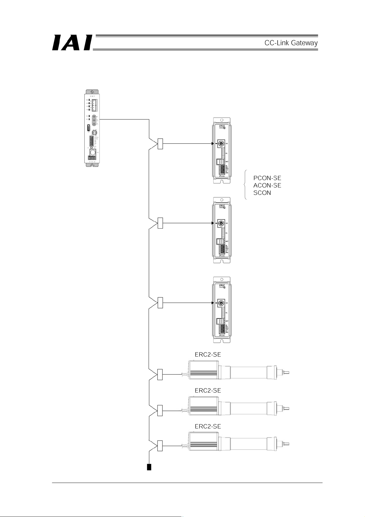
1.1 CC-Link gateway unit
CC-Link Gateway Unit (hereinafter, referred to as CC-Link gateway or gateway unit) is a unit to connect the
network of CC-Link communication protocol for an upper programmable controller (hereinafter, referred to as
PLC) and SIO communication network (Modbus communication protocol) for a controller (for robo-cylinder)
which is a sub-network.
Physical standard for SIO communication network is RS-485, and slave addresses on this network are 1-16.
All data exchanged between the CC-Link and the Modbus protocol communication network are once stored in
the internal memory of the gateway unit, and transmitted to CYCLIC. The gateway unit is handled from the
PLC side as a remote I/O.
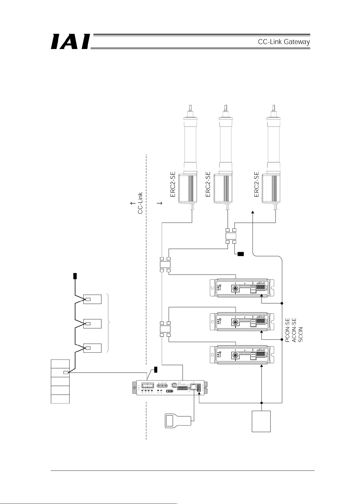
Adaptable controllers are PCON-SE, ACON-SE, SCON and ERC2-SE.
* Gateway is communication terminology, and is equipment which mutually converts data of which media and
protocols are different on networks, and allows for communication.
1
Page 6
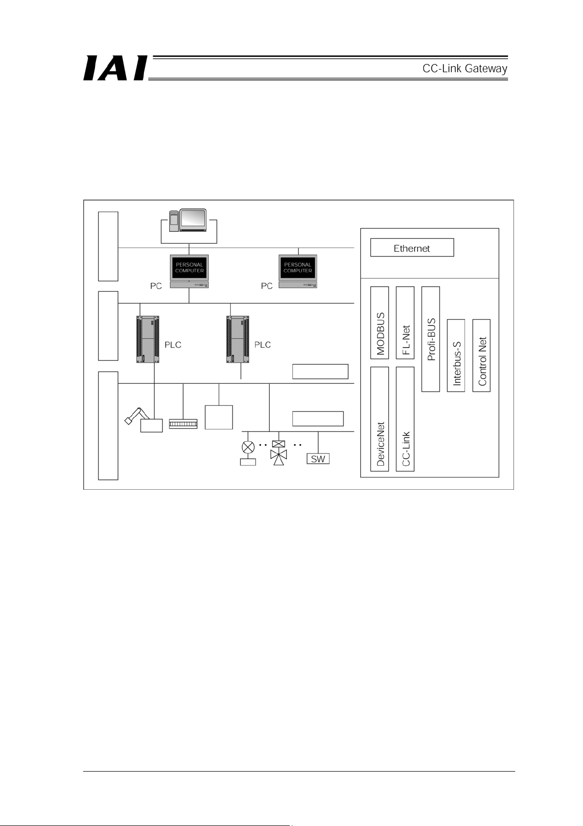
1.2 What is CC-Link
(1) System of FA communication
For FA communication, communication specifications depend on equipment on the communicating end,
content of information and its purpose, however, are roughly divided into information level, controller
level and field level as shown in the following diagram.
Primary open network
FA computer
Information level Controller level Field level
Device level
Robot
Motor
driver
Remote I/O
Installed
instrument
Solenoid
valve
Sensor level
Limit switch
(2) Information level
This is mainly used to transmit production information to an information terminal, and is referred to as
“PLC upper network.” Ethernet is mostly used for this level.
(3) Controller level
This frequently handles real time information for a production line, and is referred to as “Network
between PLCs.”
(4) Field level
This is referred to as “PLC lower network,” and is mainly used to save wiring for a control system of
which one controller is in charge, and is positioned as “Wiring save communication.”
This level is largely classified into device level and sensor level.
2
Page 7

(5) CC-Link
CC-Link has become wide spread mainly for FA as an open network for device level. Communication
specifications are open to the public, therefore, equipment in compliance with CC-Link can be
communicated without a program regardless of manufacturer.
Presently, CC-Link is spread and operated by CC-Link association (CLPA: CC-Link Partner Association),
which is a non-profitable organization.
Main features are as follows.
[1] Highly perfected saved wiring communication which has realized complete multi-vendor connection.
[2] This is a unified standard, therefore, it can be used even overseas.
[3] Since slave equipment is handled as a PLC remote I/O to which CC-Link unit is installed,
communication can be made without a particular program.
[4] Since line efficiency is high, communication with high-speed response can be made.
※ For details of CC-Link, refer to Operation Manuals of the master unit and the PLC to be installed.
Use this Operation Manual together with the Operation Manual of the controller to be connected.
This CC-Link gateway cannot be used in ways other than those for which this Operation Manual expressly
allows. Further, do not perform setting and wiring other than those for which this Operation Manual
expressly allows.
1.3 Application example of gateway unit
Application example is shown on the network in the following diagram.
CPU unit CC-Link
unit
(master
station)
Remote I/O
station
CC-Link gateway
(remote device
station)
Remote I/O
station
SIO communication network (Modbus)
Remote I/O
station
3
Page 8

1.4 Features
For CC-Link gateway, operation modes of the following four patterns can be selected.
(1) Position data limit designation mode
Only position data can be directly designated, and the maximum connecting axis number totals 14
axes.
Further, various status signals can be input and output, and present position data can be read.
Speed, acceleration and deceleration can be set for parameters for each axis as fixed values.
(2) Position No. designation mode
This is a mode to designate No. of position table for operation, and the maximum connecting axis
number totals 14 axes.
Position data, speed, acceleration and deceleration are input into the position data table of each axis in
advance. Input and output of various status signals and completed position No. can be read.
(3) Positioning data designation mode
This is a mode to directly designate position data for operation, and there are two patterns of normal
positioning and push operation.
[1] Normal positioning mode
This mode directly designates speed, acceleration and deceleration in addition to position data, and
the maximum connecting axis number totals 7 axes.
Further, input and output of various status signals and present position data can be read.
[2] Push operation mode
Push operation can be performed, and the maximum connecting axis number totals 3 axes.
This is a mode in which direct designation of current limit value (%) and positioning width for push is
added to the normal positioning mode.
(4) Simple direct value/Position No. designation mode
This mode can mix position No. designated axis and simple direct value designated (position data is
designated by numeric value, and the other movement data is designated by position table) axis.
Axis number is assigned from position No. designated axes, and subsequently, it is necessary to assign
the number to simple direct value designated axis. Depending on the size of the assignment area,
there is a Large pattern (88 words respectively for input and output), Middle pattern (68 words
respectively for input and output) and Small pattern (34 words respectively for input and output), and
the maximum connecting axis number totals 16 axes.
This Manual only describes content which can be controlled by using the Gateway unit. Content of this Manual
takes precedence over content of the Operation Manual for the controller. For detailed contents of functions,
parameter settings and alarms, refer to the Operation Manual for the controller.
4
Page 9
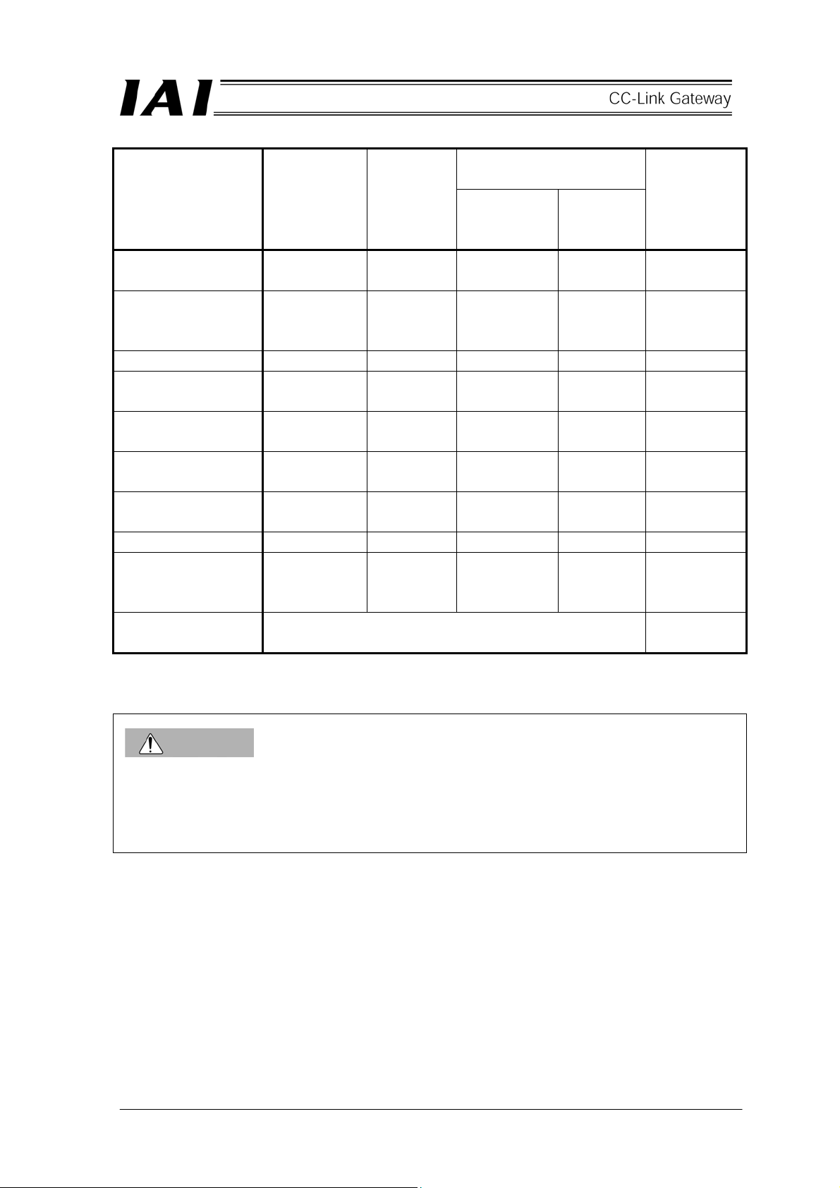
Operation mode and primary functions
Positioning data designated
Position data
Primary functions
Position data
designated operation
Speed, acceleration
and deceleration direct
designation
Push operation
Present position
reading
Position No. designated
operation
Completed position No.
reading
Connectable axis
number
Settable axis No. (*1) 0 - 13 0 - 13 0 - 6 0 - 2 0 - 15
Position data
designated maximum
value (*2)
Operable CC-Link
version
limit designated
mode
○ × ○ ○ ○
× × ○ ○ ×
× ○ × ○ ○
○
× ○ × × ○
× ○ × × ○
14 14 7 3 16
327.67mm
Position No.
designated
mode
Designated
to position
table
Ver. 1, Ver. 2 Ver. 2
Normal
positioning
mode
327.67mm 9999.99mm
mode
Push
operation
mode
○ ○ ○
Simple direct
value/Position
No. designated
mode
CAUTION
*1 A range of effective axis No. which is set to axis connected by SIO communication. Values set
exceeding this range are ignored. This case does not generate an alarm.
*2 In the case of position data direct designated operation, maximum value of position data is limited by
limiting data length of input and output register.
5
Page 10

1.5 How to identify model
Basic model For CC-Link
RCM-GW-CC
Gateway unit
6
Page 11
2. Specifications and name of each part
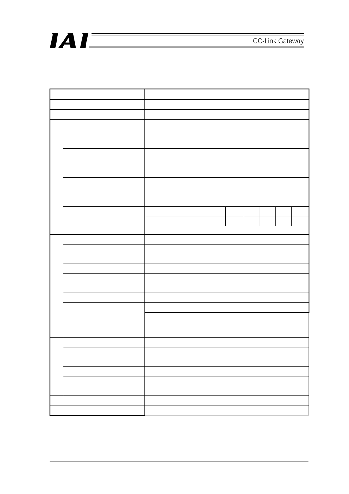
2.1 General specifications
Item Specification
Power supply 24V DC ±10%
Consuming current 300mA max.
Communications standard CC-Link Ver1.10 (*1)
Communications speed 10M/5M/2.5M/625k/156kbps (Selection with rotary switch)
Communications system Broadcast polling system
Synchronization system Frame synchronization system
Encoding system NRZI
Transmission path format Bus format (EIA RS485 conformance)
Transmission format HDLC conformance
Error control system CRC (X16 + X12 + X5 + 1)
CC-Link specification
Number of occupied stations Remote device station 4 stations
Communications speed (bps) 10M 5M 2.5M 625k 156KCommunications cable length
(*2)
Communication cable CC-Link dedicated cable
Transmission path configuration Our dedicated multi-drop difference communication
Communications system Half-duplex
Synchronization system Asynchronous type
Transmission path format Equivalent to EIA RS485 2-wire type
Communication speed 30.4kbps
Error control system No parity bit, CRC (*3)
Communication cable length Total cable length 100m or shorter
Connecting unit number Maximum 3/7/14/16 axes (depending on operation mode)
Overall cable length (m) 100 160 400 900 1200
Communication cable Two-paired twist-pair shielded cable
SIO communication specification
Operating ambient temperature 0 - 40°C
Operating ambient humidity 85%RH or less (non-condensing)
Operating atmosphere Not subject to corrosive gas, flammable gas, oil mist, powdered dust
Storage temperature -10 - 65°C
Environmental
Storage humidity 90%RH or less (non-condensing)
Vibration resistance 4.9m/s2 (0.5G)
Protection class IP20
Weight 480g or less
(*1) Certification has been acquired
(*2) For T branch communication, refer to the Operation Manuals for the master unit and PLC to be
mounted.
(*3) CRC: Cyclic Redundancy Check
Data error detecting method which is mostly used for synchronizing transmission
(Recommended brand: Taiyo Electric Wire & Cable
HK-SB/20276×L 2P×AWG22)
7
Page 12
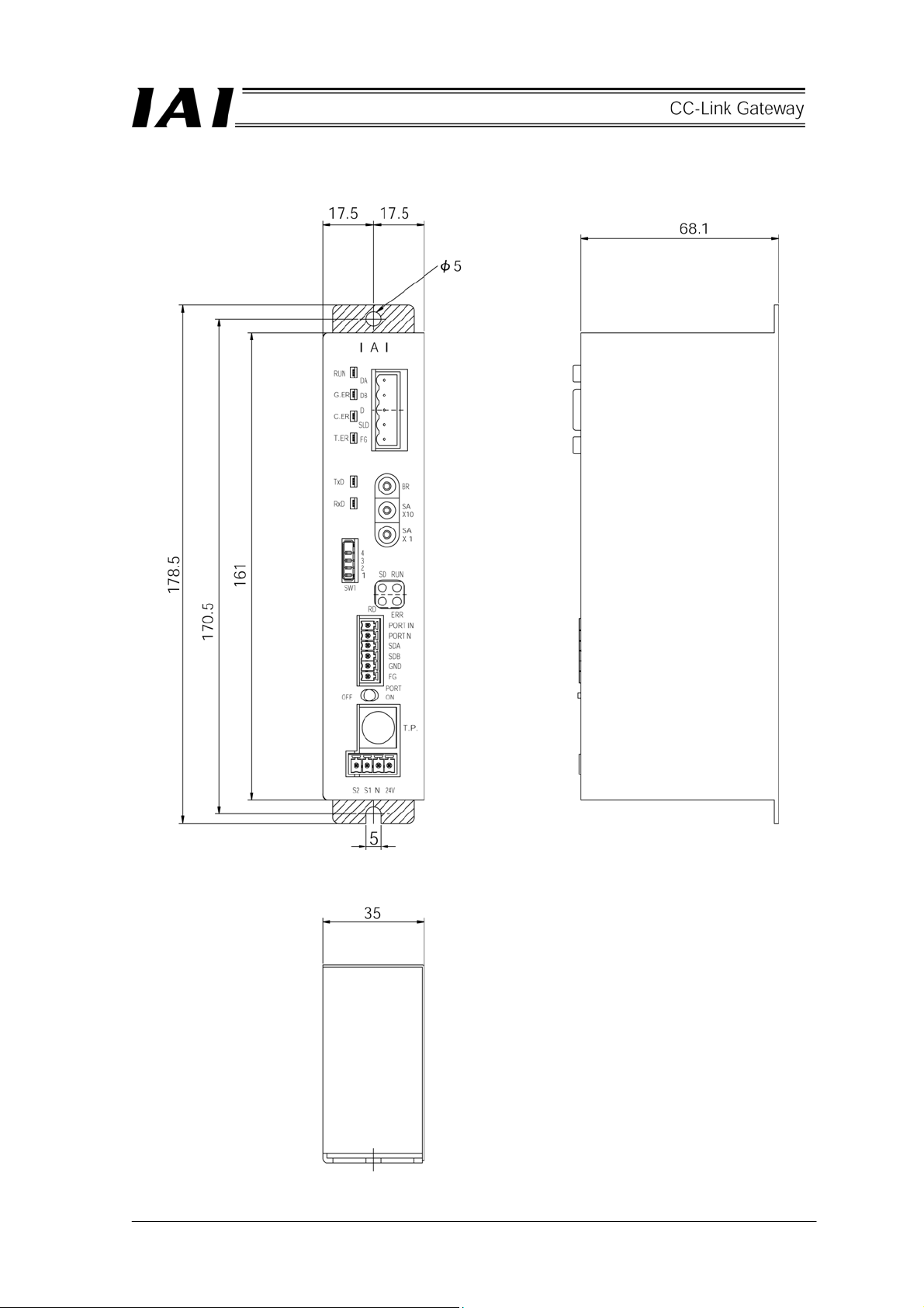
2.2 External dimension drawing
(Mounting dimension)
8
Page 13

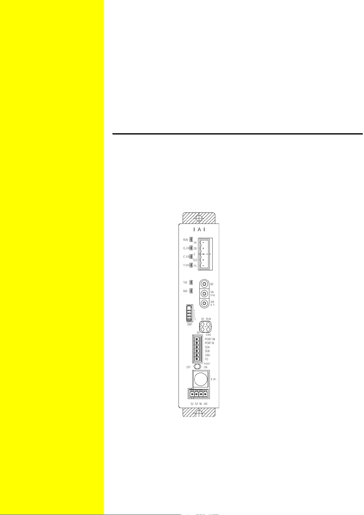
2.3 Name and function of each part
[1] Gateway status
indication LED
RUN: Normal
G.ER: Error
C.ER: CC-Link error
T.ER: SIO link error
[2] SIO communication
status LED
TxD: Data transmission
RxD: Data reception
[3] Mode setting switch
[SIO communication connector]
[4] External port switching input
PORT IN
PORT N
[5] Controller communication line
SDA: Communication line
SDB: Communication line
GND: Ground
FG: Frame ground
Port switching
[6] CC-Link communication
connector
DA: Communication line
DB: Communication line
DG: Ground
SLD: Shield
FG: Earth
[7] CC-Link setting switch
BR: Baud rate
SA × 10 and Sa × 1:
Station No. (Decimal,
2 digits)
[8] CC-Link communication
status LED
SD: Data communication
RD: Data reception
RUN: Normal
ERR: Error
[9] Port switch
ON: Port on
OFF: Port off
[10] Connector for teaching box
and personal computer
[11] Power supply input connector
9
Page 14
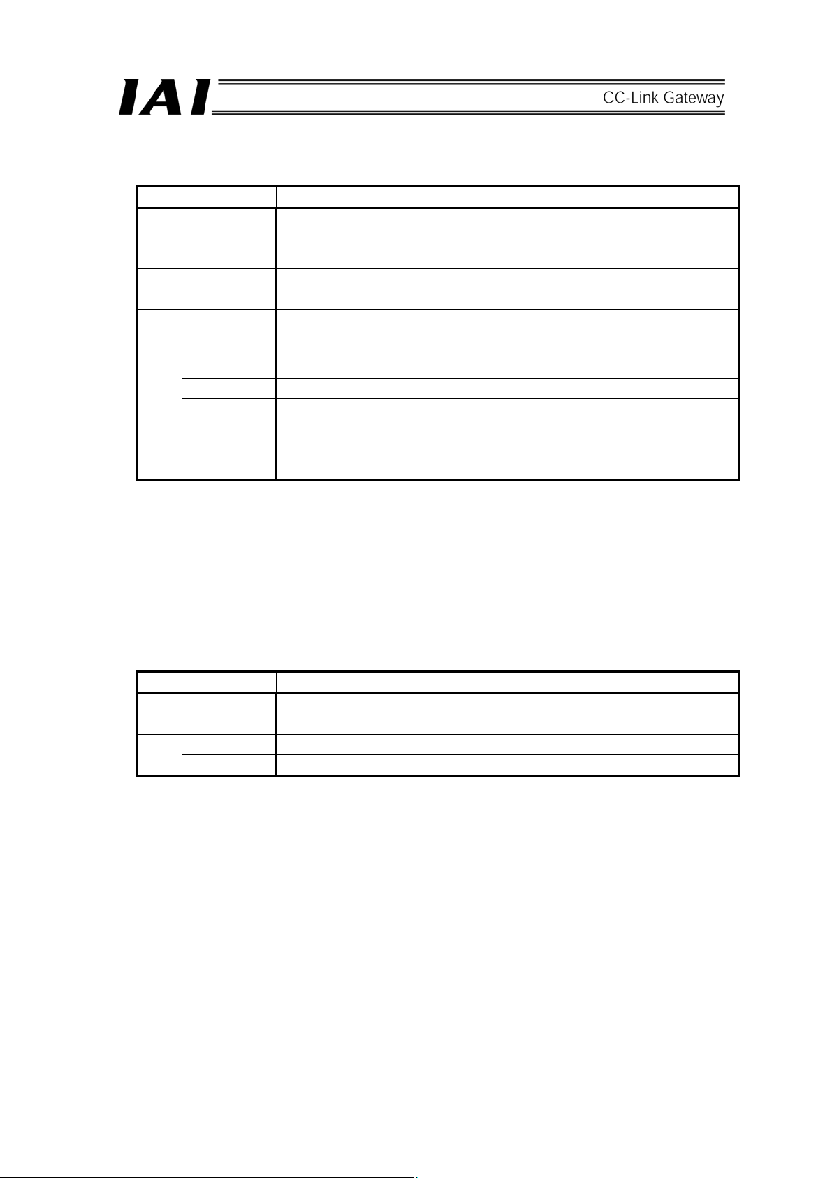
[1] Gateway status indication LED
Indicating status Description
Lit in green Indicates that the CPU of the gateway is operating. RUN
Unlit Indicates CPU operation stop status, and indicates that there is an error in the
CPU of the gateway when this is not lit even if power is turned on.
Lit in red Gateway CPU is in error, major fault stop status. G. ER
Unlit Normal
C.ER
T. ER
* CRC: Cyclic Redundancy Check
Lit in red
Flash in red This flashes at an interval of one second in the case of port on status.
Unlit Normal
Lit in red Communication error occurs in communication between the CC-Link gateway
Unlit Normal
Data error detecting method which is mostly used for synchronizing transmission
A status that CC-Link is in error, or CC-Link connection is not recognized from
the gateway CPU. (Check CC-Link communication status in [8].)
It is necessary to connect the teaching box or personal computer supporting
software if the RUN is lit even when this LED is lit.
and controller (No response, overrun, framing error or CRC(*) error) Normal
[2] SIO communication status LED
Communication status between CC-Link gateway and controller can be checked.
This LED flashes when communication between the upper PLC and controller is being performed through
CC-Link gateway, or communication is being performed with the controller by connecting the teaching box
or personal computer supporting software to the CC-Link gateway.
Indicating status Description
Flash in green Data is transmitting (from the CC-Link gateway to controller) TxD
Unlit Data transmission is suspended (from the CC-Link gateway to controller)
Flash in green Data is receiving (from controller to the CC-Link gateway) RxD
Unlit Data reception is suspended (from controller to the CC-Link gateway)
10
Page 15
[3] Mode setting switch
This switch sets the operation mode of the CC-Link gateway.
Turn off the power for the CC-Link gateway to operate this switch.
When selecting No.1, No.3 and No.4, setting of the position table for the controller is disabled.
No.
1
2
3
4
5
6
7
SW1
4 3 2 1
× × × ×
× × ○ ×
× ○ × ×
× ○ ○ ×
× × × ○
×
○ × × ○
× ○
Description
Position data limit designating mode
Position No. designating mode
Position/speed/acceleration and deceleration
designating mode
Push operation enable mode
Simple direct value/Position No. designating mode
Large
Simple direct value/Position No. designating mode
Middle
Simple direct value/Position No. designating mode
Small
Input and output byte
number
Output Input
46 46
46 46
46 46
46 46
176 176
136 136
68 68
[4] External port switching input
Connector port for teaching box and personal computer can be switched ON/OFF by external signal
(no-voltage contact).
When the port switch [9] for the CC-Link gateway main body is OFF, this input is enabled, and when the
input signal is ON, the port is turned ON. (Refer to the [9] port switch.)
[5] Controller communication line
This is a wiring connecting terminal for the communication line of the SIO communication (Modbus)
connector.
[6] CC-Link communication connector
This is a wiring connecting terminal for the CC-Link communication.
11
Page 16
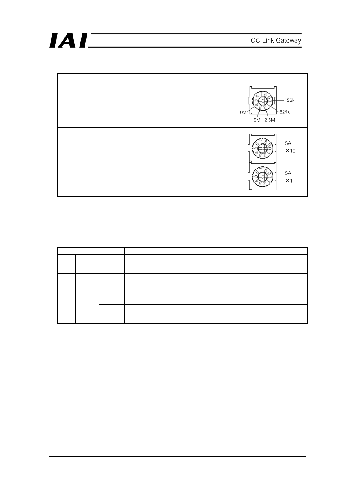
[7] CC-Link setting switch
Switch Description
[Baud rate setting switch]
This switch sets the communication rate.
Setting of 5 or higher is prohibited.
BR
[Station No. setting switch]
This switch sets with decimal two digits, however,
effective setting is from 1 to 64.
Positions of SA × 10 ・・・10 are set.
SA × 10
SA × 1
* When changing the setting with the power on, the ERRLED of the next [8] is lit.
Positions of SA × 1・・・1 are set.
(Example) When setting station No. 12,
set 1 to SA × 10, and
set 2 to SA × 1.
[8] CC-Link communication status LED
Operating status of the CC-Link gateway and network status can be checked by the four LEDs.
Indicating status Description
Lit Normal operation (Lit by starting communication) RUN Green
Unlit Does not participate in network or time out status (Communication is
interrupted for a certain time or longer)
ERR Red
Lit Reception data to self station is abnormal (CRC error).
Setting of baud rate setting switch or station No. setting switch is changed
during communication.
Unlit Normal
Lit Data is being received RD Green
Unlit No reception data
Flashing Data is being transmitted SD Green
Unlit No transmission data
12
Page 17

[9] Port switch
This is a switch to enable the connector (T.P.) for teaching box and personal computer (PORT
ON=Communication start).
When connecting and disconnecting the teaching box and the communication cable connector for
personal computer supporting software, turn OFF this switch. When using this switch, turn ON after
connecting the connector.
(Also pay attention to signal status of the port switching input [4].)
For communication rate between the teaching box, personal computer supporting software and the
CC-Link gateway, up to 115.2kbps can be set. And, the communication rate between the CC-Link
gateway and the controller is fixed to 230.4kbps.
When the PORT is ON, the CC-Link communication does not become abnormal, however, data
communication for SIO communication stops. Therefore, output signal (data) from the PLC is not
outputted to the controller, and input signal (data) from the controller keeps a value immediately before
PORT was ON.
PORT ON status signal (TPC) is outputted from the CC-Link gateway to the PLC, therefore, performs
processing such as interlock if necessary.
[10] Connector for teaching box and personal computer
This is a connecting connector for the teaching box and personal computer.
[11] Power supply input connector
This is a connecting connector for the power supply (24V DC) for the CC-Link gateway.
13
Page 18
3. Installation and Noise Elimination
Pay sufficient attention to the installation environment.
3.1 Installation Environment
a. Since the gateway unit is not dust-proof or waterproof (oil proof), avoid using the gateway unit in a
place subject to significant dust, oil mist or splashes of cutting oil.
b. Do not expose the gateway unit to direct sunlight or radiating heat from a large heat source such as
heat treatment furnace.
c. Use the gateway unit in an environment free from corrosive or inflammable gasses, under a
temperature of 0 to 40°C and humidity of 85% or less (non-condensing).
d. Use the gateway main body where it will not receive any external vibration or shock.
e. Prevent electrical noise from entering the gateway main body or its cable.
3.2 Power Supply
The power supply specification is 24V DC±10%. (Supply current: 300mA max.)
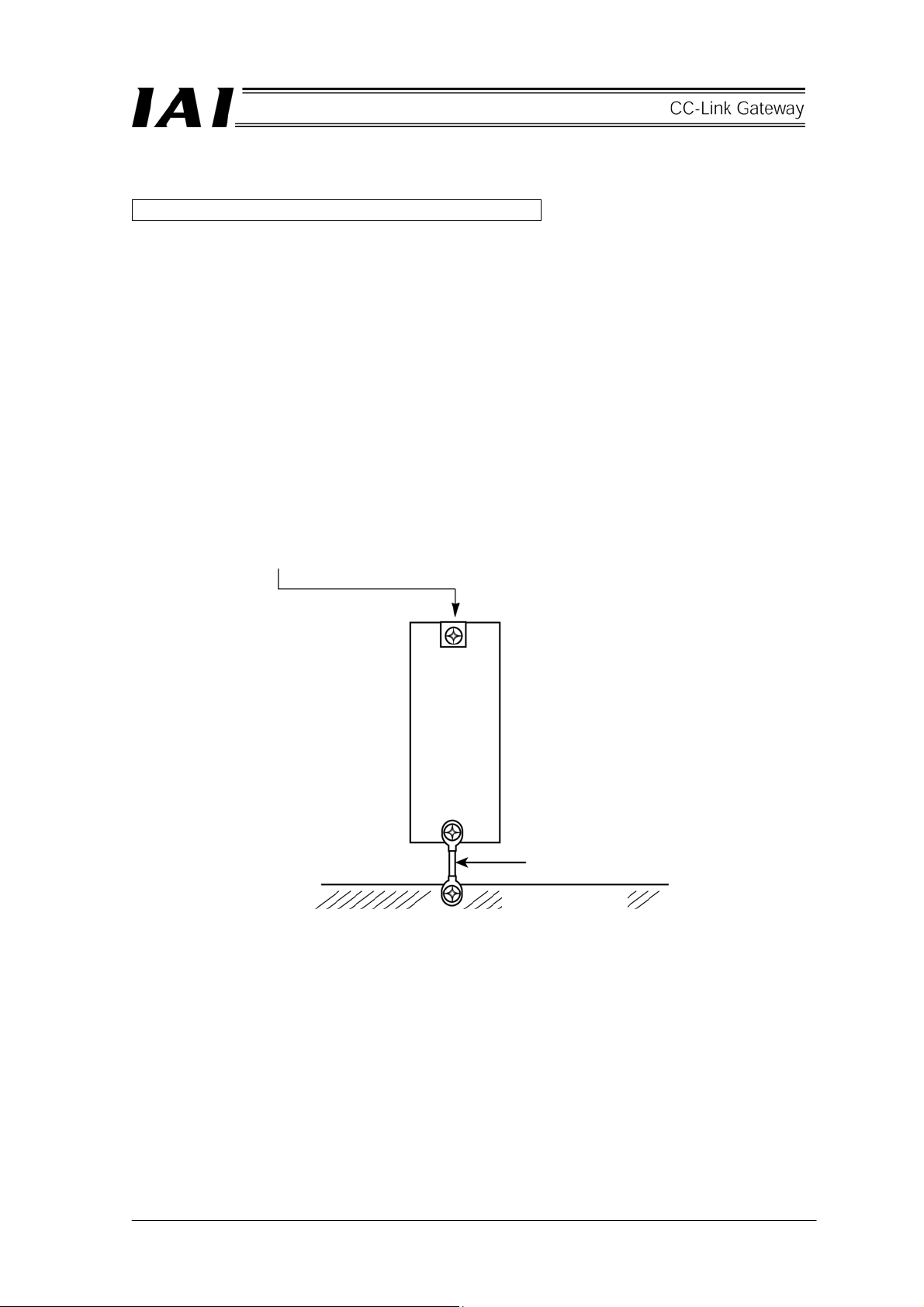
3.3 Noise Elimination and Grounding
a. Installation of gateway unit main body
Directly fix the gateway unit main body to the metallic enclosure with screws for connection.
14
Use a cable of the maximum
possible size and keep the wiring
length at a minimum.
Metallic enclosure
* Provide a dedicated class D grounding (Third class).
Page 19
b. Precautions regarding wiring method
Separate the communication lines for the gateway unit and the wiring for the CC-Link
communication line from high-power lines such as a cable connecting to a power circuit. (Do not
bundle together wiring for the communication lines with high-power lines or place them in the same
cable duct.)
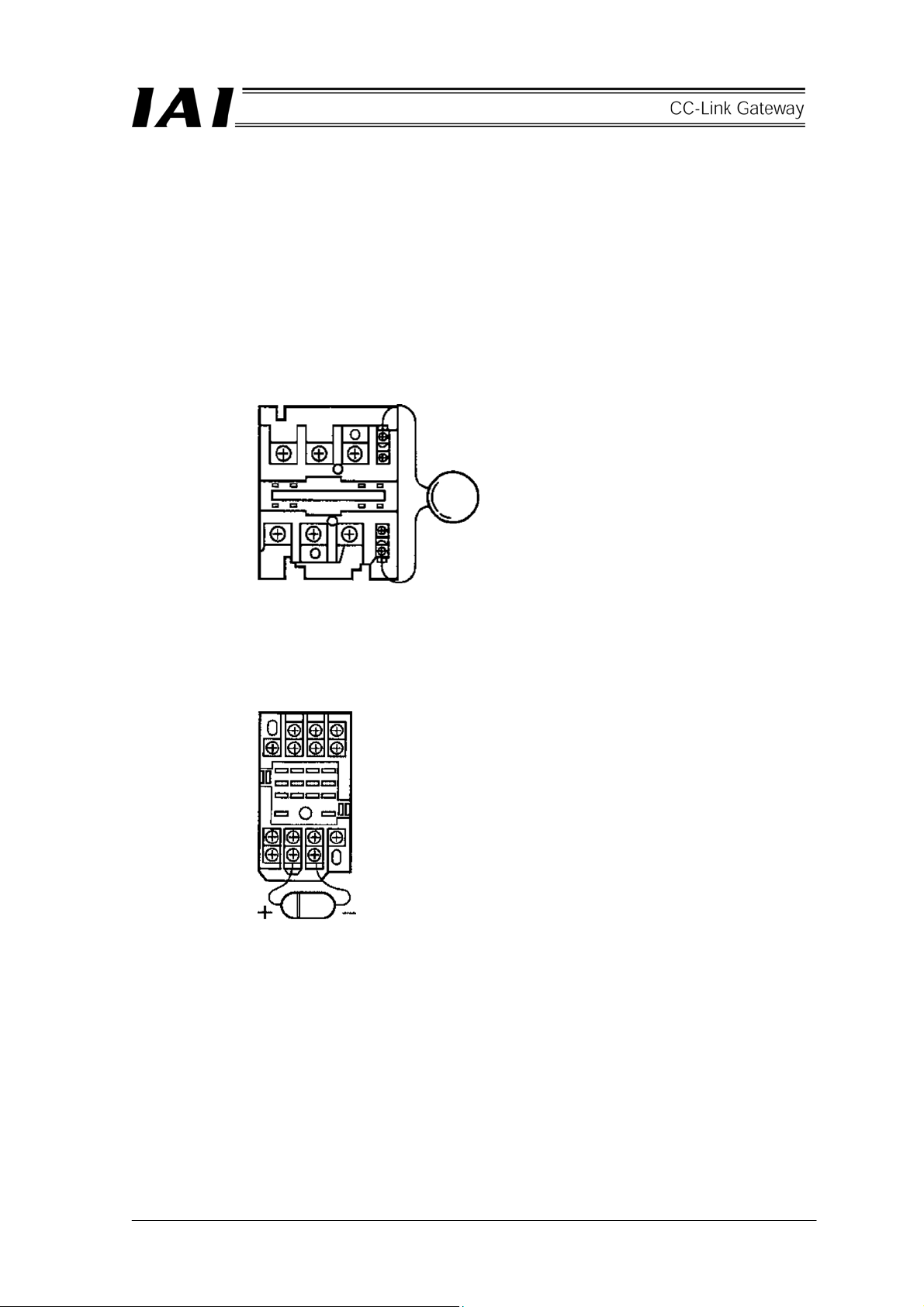
c. Noise sources and elimination
Among the numerous noise sources, solenoid valves, magnet switches and relays are of particular
concern when building up a system. Noise from these sources can be eliminated by implementing
the measures specified below.
[1] AC solenoid valves, magnet switches and relays
Measure: Install a surge absorber in parallel with the coil.
[2] DC solenoid valves, magnet switches and relays
Measure: Install a diode in parallel with the coil. Determine the diode capacity in accordance
with the load capacity.
← Point
Install a surge absorber to each
coil over a minimum wiring
length. Installing a surge
absorber to the terminal block or
other part will be less effective
because of a longer distance
from the coil.
In a DC circuit, connecting a diode in reverse polarity
will damage the diode, internal parts of the controller
and/or DC power supply, so exercise sufficient caution.
15
Page 20
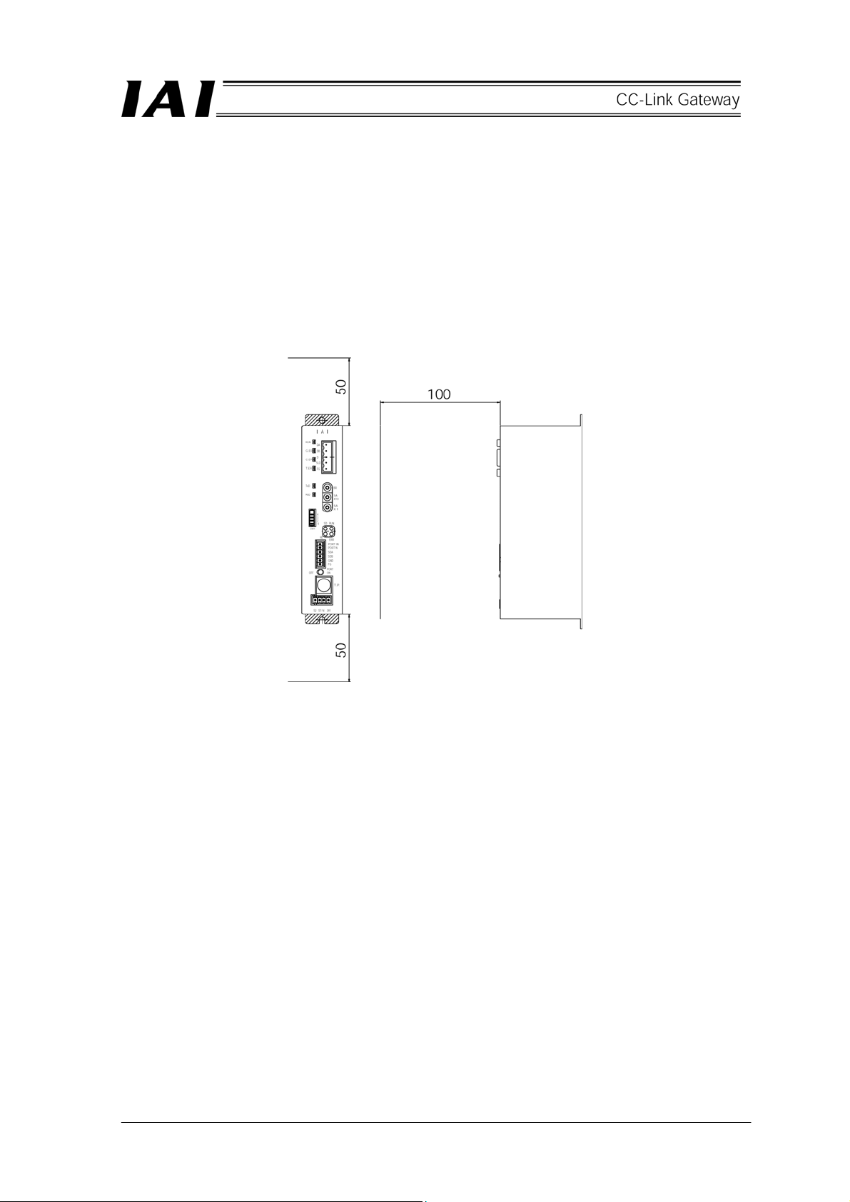
3.4 Installation
Design the control box size, installing position of the gateway unit and cooling method of the control box in
such a way that the temperature around the gateway unit will not exceed 40°C.
Install the gateway unit vertically on a wall, as shown below, and provide a minimum clearance of 50mm
above and below the gateway unit and a minimum clearance of 100mm on the front for wiring.
For lateral installation such as installing multiple gateway units side by side, secure a sufficient space so that
the gateway unit is easily installed and removed.
If affection of heat or noise is a concern, take the measure into account.
16
Page 21
r
r
4. Wiring
4.1 Overall Configuration
The following diagram shows an example of configuration to build a CC-Link by using a gateway unit.
Terminal resisto
Slave station
Gateway unit
SIO communication network
4-direction junction
Terminal
resisto
Terminal resistor
Host system (PLC master station)
Teaching box
24V
power
supply
17
Page 22
SIO communication connection is allowed even by multi-drop method using terminal blocks as follows.
Gateway unit
Terminal block
18
Terminal resistor
Page 23
r
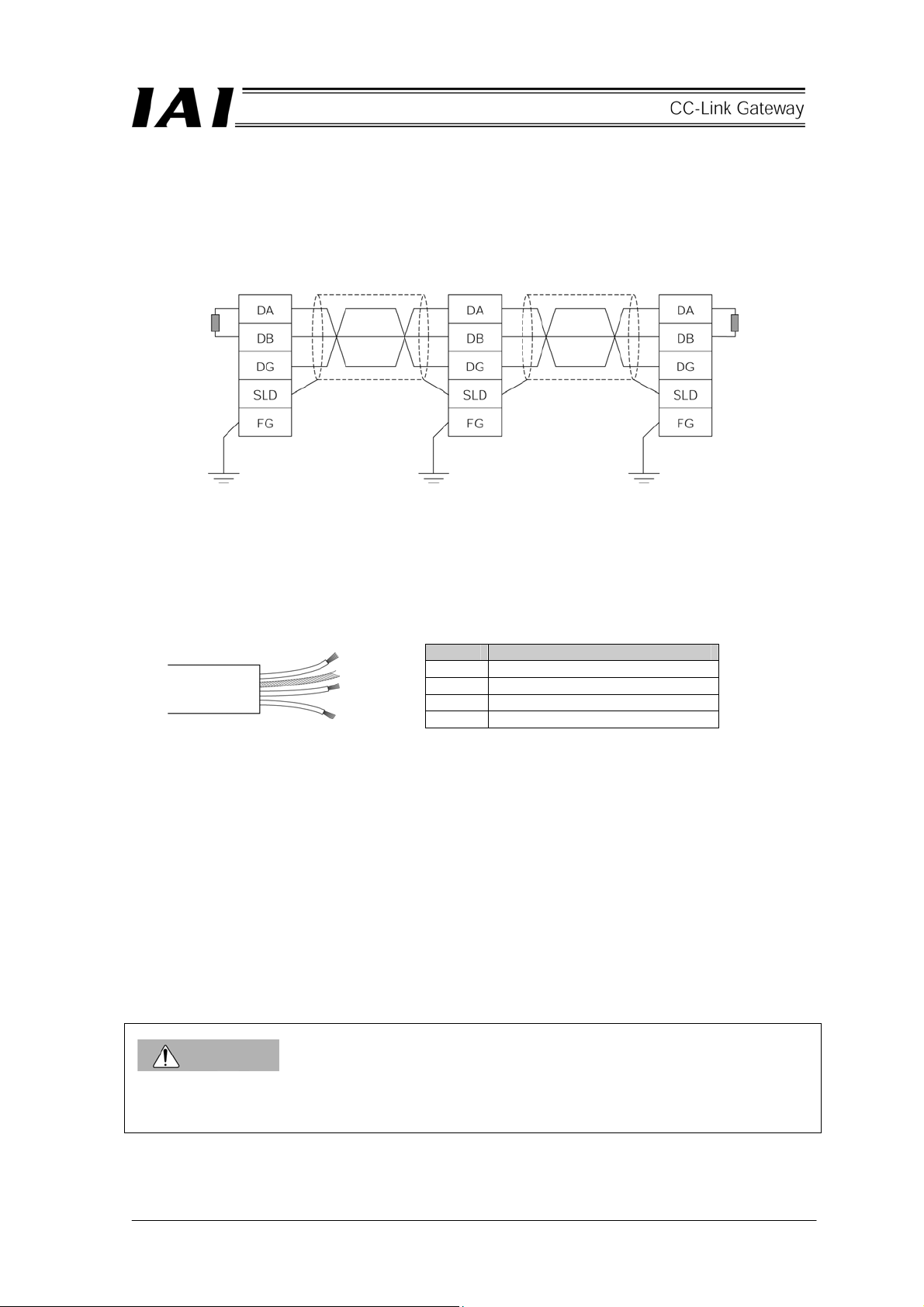
Reference Outline of CC-Link network configuration
For details of the CC-Link, refer to the Operation Manual for the master side (PLC). This section
describes a point for network wiring.
The following diagram shows an example of network connection.
Terminal resisto
Master station Slave station Slave station
(Blue)
(White)
(Yellow)
Terminal resistor
CC-Link dedicated
cable
CC-Link dedicated
cable
(1) Equipment connected by the CC-Link is referred to as a station, and 0 to 64 can be set as a station No.
The master station and slave station can be placed on any position.
(2) Connection is made by a multi-drop method directly branching at each station, and a T-branch using
commercially available terminal block, etc., is allowed.
(3) Use a dedicated shielded 3-core twisted paired cable as a cable.
The dedicated cable is as follows.
Color Signal type
Blue Communication line A (DA)
White Communication line B (DB)
Yellow Communication ground line (DG)
- Shield (SLD)
(4) It is necessary to install terminal resistors on both ends of the CC-Link system. The terminal resistor is
connected between “DA” and “DB,” however, it differs with the cable being used.
(5) Communication rate is restricted by network length (total branch length, network maximum length).
CAUTION
Set the GND (ground) level of the power supply for each controller connected to the gateway to the power
supply for the gateway.
19
Page 24
x
A
A
y
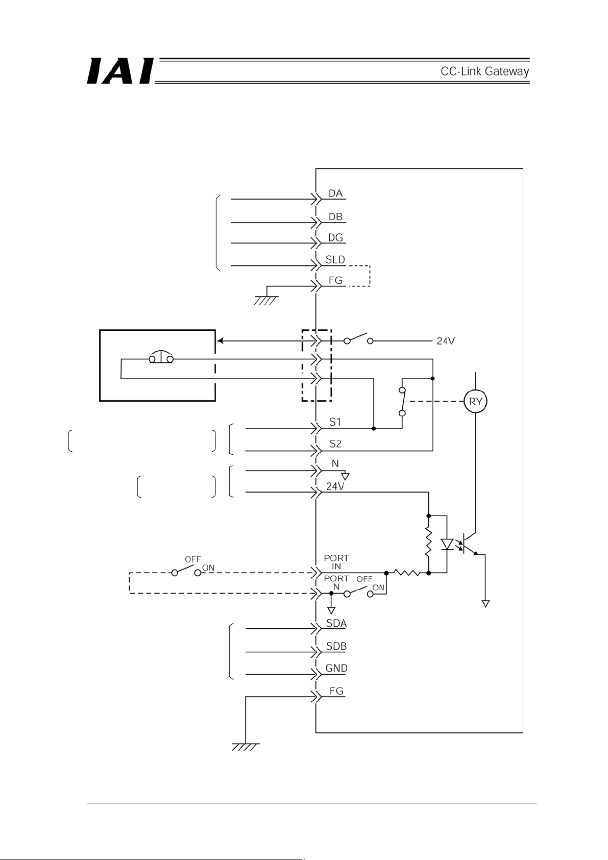
4.2 Input and output signal of gateway unit
(1) Connection diagram
(Blue)
(White)
CC-Link cable
Teaching box
(Yellow)
(Not colored)
Connector for teaching box
and personal computer
Port switch
Gateway unit
Teaching bo
Emergency stop signal output
llowable load voltage: 30V DC
llowable load current: 1A
Gateway power suppl
24V DC±10%
300mA max.
External port switching input
(Supplied by customer)
(Load 24V DC 7mA)
SIO
communication
cable
Port switch
20
Page 25

(2) Port control and emergency stop signal output
The connector port for the teaching box and personal computer can be also turned ON/OFF by an
external signal other than the ON/OFF signal from the port switch on the gateway unit main body.
Further, since the contact signal from the emergency stop pushbutton switch on the teaching box is
outputted to the outside while the port is ON, this signal can be incorporated into the emergency stop
circuit for the whole system.
External port
switching input
Port switch
OFF OFF Ineffective (S1-S2 short circuit) Ineffective
ON OFF
OFF ON
ON ON
Teaching box emergency stop
signal output
Effective (S1-S2= Teaching box
emergency stop contact)
Connector port for teaching box
and personal computer
Effective
21
Page 26

(3) Specification of input and output signal and wiring material
Connecting plug is
standard attachment.
MC1.5/6-ST3・81
(PHOENIX CONTACT)
Connecting plug is
standard attachment.
MC1.5/4-ST3・5
(PHOENIX CONTACT)
The gateway unit
incorporates a terminal
resistor, therefore,
connect the terminal
resistor to the end of the
SIO communication.
Connecting plug is
standard attachment.
It is necessary to connect
a terminal resistor to both
ends of the CC-Link
system (between DA and
DB), therefore, check the
Operation Manual for the
master side (PLC).
2
2
2
Connector and applicable electric wire
0.8 – 1.3mm
AWG 18 – 16
AWG 28 - 16
0.08 – 1.5mm
0.08 – 1.5mm
AWG 28 - 16
Specification
24V DC ±10%
Consuming current 300mA
max.
Allowable load voltage: 30V
DC
Allowable load current: 1A
No voltage (dry) contact input
load: 24V DC 7mA
Two-paired twist
shielded cable
(AWG22)
Recommended
Set GND (ground) level to that
of controller or ERC actuator
to be connected.
brand: Taiyo Electric
Wire & Cable
HK-SB/20276 XL
2P × AWG22
CC-Link Ver. 1.10
supporting
dedicated cable
(Such as
Internally connected to frame.
FANC-SBH,
FANC-SB)
Internally connected.
22
Contents
Gateway power supply Positive
24V
Symbol
side of 24V DC
Gateway power supply Negative
side of 24V DC
Teaching box emergency stop
signal output
N
S1
Power supply
input connector
S2
External port switching input
IN
PORT
SIO communication line A
SIO communication line B
N
SDA
PORT
SDB
SIO
connector
communication
Ground
Frame ground
FG
GND
CC-Link communication line A
CC-Link communication line B
CC-Link communication ground line
Shield
Frame ground
DA
DB
CC-Link
DG
connector
SLD
FG
communication
able FANC-SBH
CC-Link cable to be used, use a resistor suitable for the cable.
The gateway unit is provided with the following one terminal resistor respectively. Since the terminal resistor depends on the
able FANC-SB
CC-Link dedicated high-performance cable) 130Ω, 1/2W
CC-Link dedicated cable) 110Ω, 1/2W
Page 27
A
th
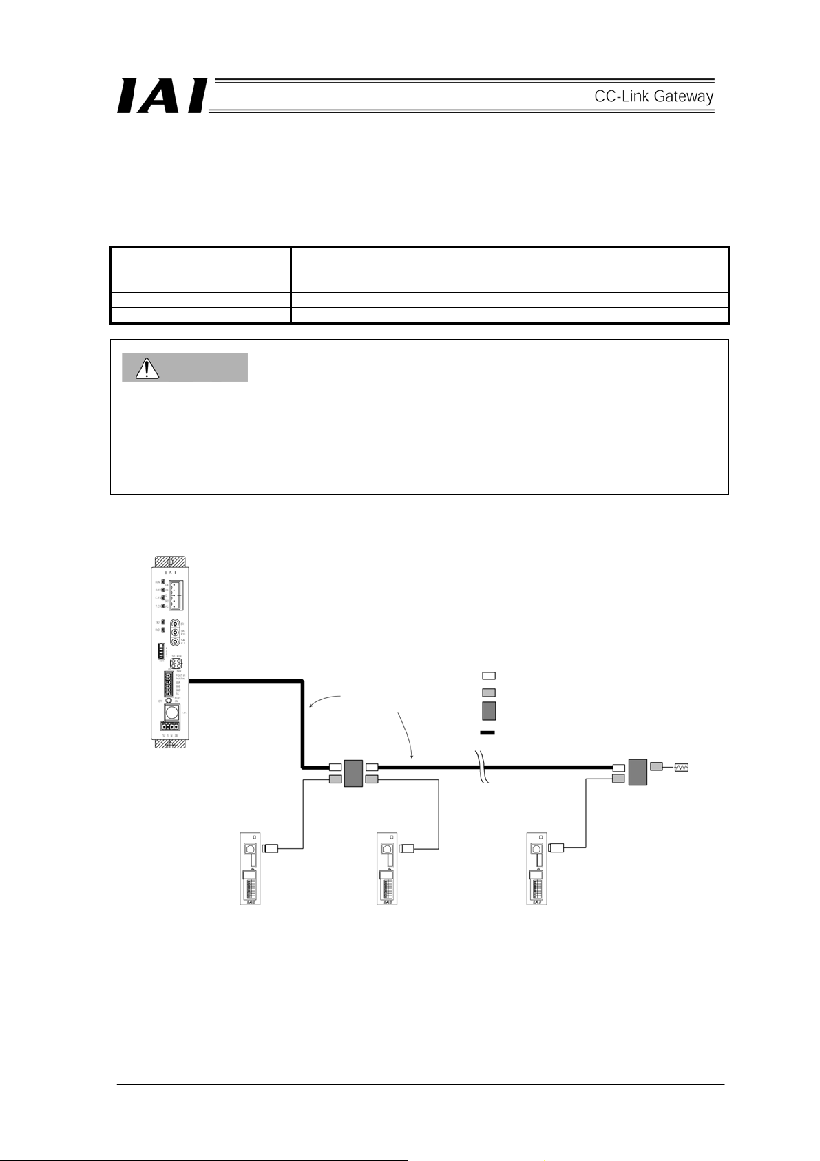
4.3 Building of SIO communication network (SIO communication)
4.3.1 Wiring
(1) Basic
Item Contents
Number of connecting units 16 axes max. (Depends on the operation mode. Refer to “1.4 Features”)
Communication cable length Total cable length 100m or shorter
Communication cable Two-paired twisted pair shielded cable
Terminal resistor Recommended cable: Taiyo Electric Wire & Cable
CAUTION
1. Provide a communication path via a bus connection, and be sure to connect a terminal resistor at the
end. A terminal resistor is incorporated into the gateway unit side, therefore, it is unnecessary to connect
it.
2. The communication cable should be supplied by customer. If the recommended communication cable
is not used, use an electric wire size AWG22.
(2) Link connection for PCON-SE, ACON-SE
Gateway unit
(Incorporating
terminal resistor)
SIO communication
main line
First axis Second axis n
e-CON connector (AMP made 4-1473562-4: Green)
e-CON connector (AMP made 3-1473562-4: Orange)
Junction (AMP made 3-1473574-4:)
Recommended brand HK-SB/20276 × L 2P ×
WG22
Terminal resistor
R=220Ω
1/4W
Controller link cable
CB-RCB-CTL002
axis
23
Page 28

a. Detail Connection Diagram
The diagram below shows the details of the SIO communication connection. The controller link cables
are optionally prepared, but the communication main line must be prepared by the customer.
Gateway unit
Two-paired shielded cable
Recommended brand:
Taiyo Electric Wire & Cable
SIO
communication
main line
Four-way junction (AMP: 5-1473574-4)
e-CON connector (AMP: 4-1473562-4)
Housing color: Green
Controller link cable
Yellow
Orange
Controller 1 Controller 2
b. Preparation of Communication Main Line
[1] Strip off approx. 15-20mm of the sheath
from the two-paired shielded cable.
[2] Install the cable protective tube.
[3] Insert three cables into the cable insertion
hole of the connector without stripping off
the envelope of the conductors.
[4] Pressure-weld the cable press-fit housing
with the cables inserted from above.
[5] Heat-treat the cable protective tube.
Pin numbers of e-CON connector
Locking tab
Yellow
Orange
e-CON connector (AMP: 3-1473562-4)
Housing color: Orange
Press wielding
Cable tube
Two-paired shielded cable
e-CON connector
Locking tab
Be sure to insert the terminal resistor (220Ω, 1/4W) into the end of the communication main line.
(between No. 1 and No. 2 of the e-CON connector)
24
Page 29
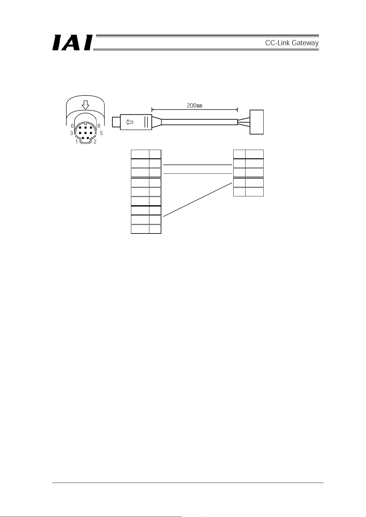
c. Controller Link Cable (CB-RCB-CTL002)
* Controller’s option
Controller end
Mini DIN connector
Signal
SGA 1
SGB 2
+5V 3
ENB 4
EMGA 5
+24V 6
GND 7
EMGB 8
Yellow
Orange
Blue
The following parts are provided together:
[1] Four-way junction
Model: 5-1473574-4, Manufacturer: MP, Quantity: 1
[2] E-Con connector
Model: 4-1473562-4, Manufacturer: MP, Quantity: 1
Compatible wire coating outline: 1.35-1.6mm
[3] Terminal resistor: 220Ω, 1/4W, with E-Con connector, Quantity: 1
1
2
3
4
E-Con connector
3-1473562-4
(Housing color: Orange)
Signal
SGA
SGB
GND
25
Page 30

th
(3) Link connection for ERC2-SE
SIO communication
main line
Gateway unit
(Incorporating
terminal resistor)
Terminal resistor
First axis
Second axis
axis
n
e-CON connector (AMP made 4-1473562-4: Green)
e-CON connector (AMP made 3-1473562-4: Orange)
Junction (AMP made 3-1473574-4:)
Recommended brand: Taiyo Electric Wire & Cable
26
Page 31

Detail connection diagram
Connection between the gateway unit and four-way junction is the same as in item (2).
Connection between each ERC2-SE and four-way junction is as shown in the following diagram.
For details, refer to the Operation Manual for the ERC2-controller.
Orange
Blue
Green
e-con connector
SIO main line
Nichiatsu Nichiatsu Nichiatsu
Four-way junction
Relay cable 2 Relay cable 1
(4) In the case of a combination of PCON-SE, ACON-SE, ERC2-SE and SCON
The previous items (2) and (3) are basic connections. Perform wiring by the method introduced in 4.1
Overall configurations.
27
Page 32

(5) Wiring of emergency stop (EMG) circuit
When incorporating an emergency stop switch on the teaching box connected to the gateway unit into an
emergency stop circuit, emergency stop signal output outputted from the “S1” and “S2” terminals for the
gateway unit can be used.
The controller for all of the connected robo-cylinders can be put into an emergency stop status by the
emergency stop switch on the teaching box connected to the gateway unit.
CAUTION
1. The following example shows a wiring path for an emergency signal, and does not show a safety circuit
(such as emergency stop reset circuit). Provide a safety circuit including an emergency stop reset
circuit, etc., on the outside for an actual emergency stop.
2. For details of emergency stop processing for the robo-cylinder, refer to the Operation Manuals for
PCON-SE, ACON-SE, SCON and ERC2-SE.
28
Page 33

p
y
[1] Example of drive signal shutdown
Teaching box
EMG push
button
Gateway unit
T.P. connector
EMG reset
switch
EMG
push
button
Gateway
ower suppl
PCON-SE controller
SIO
SIO connector
communication
Connection
detecting
Input power supply
24V DC
(2A max/one unit)
Power supply terminal block
Power supply terminal block (Unit 2)
signal (H)
EMG signal
detection
Motor drive
power
supply
Control
power
supply
(H)
Time
constant
connector
connection
detecting
Drive stop
signal (L)
circuit
SIO
Motor
drive
Power supply terminal block (Unit 3)
Caution: [1] The input current to the EMG terminal of PCON-SE is 5 mA. When connecting the
contact of the EMG relay R to the EMG terminals of multiple controllers, check the
current capacity of the relay contact.
29
Page 34

p
y
[2] Example of motor drive power shutdown
Teaching box
EMG push
button
Gateway unit
T.P. connector
EMG reset
switch
EMG
push
button
Gateway
ower suppl
PCON-SE controller
SIO
SIO connector
communication
Connection
detecting
Input power supply
24V DC
(2A max/one unit)
Power supply terminal block
Power supply terminal block (Unit 2)
signal (H)
EMG signal
detection
Motor drive
power
supply
Control
power
supply
(H)
Time
constant
connector
connection
detecting
Drive stop
signal (L)
circuit
SIO
Motor
drive
Power supply terminal block (Unit 3)
30
Page 35

4.3.2 Setting of axis No.
For PCON-SE, ACON-SE and ERC2-SE
Set axis No. for slave station No. on the SIO link.
Set the axis No. in a hexadecimal of 0 to F so that the first axis No. is 0, and 16th axis No. is F.
Axis No. is set by the teaching box or personal computer supporting software.
◎ Operation of personal computer supporting software
[1] Open the main screen. [2] Click the setting (S). [3] Move the cursor to the controller setting (c).
[4] Move the cursor to the axis No. assignment (N) and click. [5] Enter No. into the axis No. table.
◎ Operation of teaching box RCM-T
[1] Open the user adjusting screen. [2] Move the cursor to the assignment NO._ with ▼key. [3]
Enter axis No. and press the Return key. [4] Enter 2 into adjusting NO._ and press the Return key.
◎ Operation of simple teaching box RCM-E
[1] Open the user adjusting screen. [2] Open the Return key to open a screen of the assignment
NO._. [3] Enter axis No. and press the Return key. [4] Enter 2 into adjusting NO._ and press the
Return key.
For details of the setting method, refer to the Operation Manuals for the teaching box or the personal
computer supporting software.
CAUTION
1. Set an axis No. so as not to be duplicated.
2. Remove the link connection for the axis to be set for setting and changing the axis No.
3. Connect the terminal resistor between SGA and SGB on the ends.
31
Page 36

5. Outline of CC-Link
5.1 Data communication
A scheme for basic data communication of the CC-Link is as shown in the following diagram.
For slave to master station of the PLC, there are remote I/O stations which handle bit information only and
remote device stations which handle bit information and word information (numeric data).
The master station has a buffer memory which is divided into remote input RX, remote output RY and remote
register RWw/RWr. The remote input and output RX/RY handle bit information, and the remote register
RWw/RWr handle word information (numeric data). Data is automatically communicated between the master
station and slave station via this buffer memory regardless of the CPU for the PLC.
The CPU uses the buffer memory in the master station and the CPU internal device (such as X.Y.M.D.W) to
communicate data.
Slave
Network
parameter
Automatic
refresh
parameter
CPU device
corresponded to RX
(such as X.M)
CPU device
corresponded to RY
(such as Y.M)
CPU device
corresponded to
RWw (such as D.W)
Master station
Network
parameter
Buffer memory
Remote input
Remote output
Remote register
Link scan
Link scan
Link scan
Remote device station
Remote input
(bit signal)
The remote I/O
stations have
these only.
Remote output
(bit signal)
Remote register
(numeric data)
CPU device
corresponded to RWr
(such as D.W)
32
Remote register
Link scan
Remote register
(numeric data)
Page 37

* CPU internal user device for PLC
Input: X
Bit device Output: Y
Internal relay: M
Word device
Link register: W
Data register: D
5.2 Address assignment of master PLC
Number of maximum link points per one system is respectively 2048 points for remote input and output (RX,
RY) and 256 points for remote register (RWw, RWr), and a buffer memory for this size is available.
Address assignment for the master station buffer memory is as shown in a diagram on the next page.
The remote input RX is assigned to 0E0H-15F H addresses, the remote output RY is to 160 H -1DF H addresses,
the remote register RWw is to 1E0
addresses.
Number of links per one remote station is respectively 32 points (2 words) for remote input and output (RX,
RY), and 4 points (4 words) for remote register (RWw, RWr), then links of a maximum 64 stations are available
for one system.
Station No. of 1 to 64 can be set to a remote station, however, the number of exclusive stations vary with the
remote station, so it is necessary to exercise sufficient caution to set the station No.
Data communication between the internal device of the CPU and the master station buffer memory is
sometimes performed by sequence command such as FROM command and TO command, and is, in some
case, automatically performed by setting the parameters in advance (automatic refresh).
-2DFH addresses, and the remote register RWr is assigned to 2E0 H -3DF H
H
33
Page 38

CC-Link memory map (MITSUBISHI Q series)
PLC-CPU Master station buffer memory Remote station
Internal device
Automatic
refresh
Automatic
refresh
Remote input (RX)
(2 words) for
one station
Remote output (RY)
(2 words) for
one station
I/O station
Device station
Remote input
Bit data
Remote output
Automatic
refresh
Automatic
refresh
Bit data
Remote register (RWw)
(2 words) for
one station
Remote register
Word data
(numeric data)
Remote register (RWr)
(2 words) for
one station
Remote register
Word data
(numeric data)
34
Page 39

g
g
g
g
6. Address configuration of gateway
As described in 1.4 Features of gateway unit, actuators can be roughly operated by five modes.
Address configuration as a slave depends on each mode.
6.1 Gateway control signal
This is a signal to control the gateway, and consists of respective two words of word register for input and
output.
It is recommended to use data of this word register on the bit register by performing transmission processing.
ON/OFF control for communication of SIO link, and monitoring of communication status of SIO link and status
of gateway can be performed.
PLC output
(RY00)
(RY10)
Gateway
control
si
nal 0
Gateway
control
nal 1
si
1 word = 16 bits
PLC input
(RX00)
(RX10)
Gateway
status
nal 0
si
Gateway
status
nal 1
si
1 word = 16 bits
35
Page 40

Details of input and output signal
Signal type Bit
Control
signal 0
PLC output
Control
signal 1
15 MON
14 - 8 -
7 NPS4
6 NPS3
5 NPS2
4 NPS1
3 NPS0
2 PPS2
1 PPS1
0 PPS0
15 CFG15 Link ON Axis No.15
14 CFG14 14
13 CFG13 13
12 CFG12 12
11 C F G 11 11
10 CFG10 10
9 CFG9 9
8 CFG8 8
7 CFG7 7
6 CFG6 6
5 CFG5 5
4 CFG4 4
3 CFG3 3
2 CFG2 2
1 CFG1 1
0 CFG0 0
Signal
name
Contents
Link communication starts at ON, and stops at OFF.
When all of CFG15 to 0 (link connection axis selection) are OFF, do not
turn ON MON signal.
Further, while MON signal is ON, do not turn OFF all of CFG15 to 0.
When all of CFG15 to 0 are OFF and MON signal is ON, the gateway
unit becomes SIO link error, and the LED (T.ER) on the front of the unit
is lit.
This cannot be used.
Always turn this OFF (0).
Use this in simple direct value/position No. designating mode.
In another mode, always turn this OFF (0).
Set number (0-16) of axes used in position No. designating mode by 5
bit binary.
Use this in simple direct value/position No. designating mode.
In another mode, always turn this OFF (0).
Set I/O pattern (pattern 0-5) for position No. designating mode axis by
3 bit binary.
Set axis No. to which the link is
connected.
Link is connected at ON (1), and is
released at OFF (0).
Even while MON signal is ON,
ON/OFF is allowed.
(Note)
● Do not turn ON axis No. which is
not actually connected.
● Do not turn ON axes other than
settable axis No. which is selected
by the mode setting switch.
SIO link error occurs in each case.
36
Page 41

Signal type Bit
Control
signal 0
PLC input
Control
signal 1
Signal
name
Gateway unit now normally
operating output
15 RUN
Gateway unit error detection output This is turned ON when major
14 G.ER
SIO link communication error
detection output
13 T.ER
Port switch ON output This outputs status of the port
12 TPC
11 MOD4 Mode setting switch 4 ON output
10 MOD3 Mode setting switch 3 ON output
9 MOD2 Mode setting switch 2 ON output
8 MOD1 Mode setting switch 1 ON output
7 Major V.4
6 Major V.2
5 Major V.1
4 Minor V.16
3 Minor V.8
2 Minor V.4
1 Minor V.2
0 Minor V.1
15 LINK15 Link is being connected. Axis No.15
14 LINK14 14
13 LINK13 13
12 LINK12 12
11 L I N K 11 11
10 LINK10 10
9 LINK9 9
8 LINK8 8
7 LINK7 7
6 LINK6 6
5 LINK5 5
4 LINK4 4
3 LINK3 3
2 LINK2 2
1 LINK1 1
0 LINK0 0
Outputs Major Version No. by 3 bit
binary.
Outputs Minor Version No. by 5 bit
binary.
Contents
This is turned ON while
gateway unit is normally
operating. This is synchronized
with light up of the LED (RUN)
on the front of the unit.
fault stop status is detected.
This is synchronized with light
up of the LED (G.ER) on the
front of the unit.
This is turned ON when
communication error of the SIO
link is detected. This is
synchronized with light up of the
LED (T.ER) on the front of the
unit.
switch on the front of the unit.
This is turned ON when the port
switch is ON.
This outputs setting status of
the mode setting switch.
This outputs version information
of gateway unit. This may be
checked when any fault occurs.
Keep this in a status that this is
read by the PLC.
Example) In the case of Ver.
1.03
Major Version No.=1
(Data is 001)
Minor Version No.=3
(Data is 0011)
For axis for which link
connection is selected by
CFG15-0, link connection
becomes effective when MON
signal is ON.
Signal for link connection
effective axis is turned ON.
37
Page 42

6.2 Position data limit designation mode
This is an operation mode in which function of the controller is limited only to positioning, and allows for control
of a maximum 14 axes.
Position data for positioning is directly written in the data register of the PLC, and operation is performed.
Communication for setting of speed, acceleration and deceleration cannot be performed.
Speed, acceleration and deceleration are set to parameter No.8 “Speed initial value” and No.9 “Acceleration
and deceleration initial value” for each axis.
Setting of position table for each axis is unnecessary.
Primary functions controllable in this mode are as shown in the following table.
○: Direct control
Primary functions
Home return operation
Positioning operation
Speed, acceleration and
deceleration setting
Pitch (incremental) feed
Push operation
Speed change during movement
Operation in different acceleration
and deceleration
Pause
Zone signal output
PIO pattern selection
* There is no strobe signal in the present position data. Therefore, when checking the present position by the
PLC during movement, provide a range to check that there is data of 2 scans or more in the range.
△: Indirect control
×: Ineffective
○
○
△
△
×
×
×
○
△
×
Remarks
This is set to a parameter.
Therefore, this is fixed during operation.
Pitch feed data cannot be directly processed.
Give command by adding or subtracting data of
same moving amount to/from the present position
by host PLC.
Monitor the present position data by the PLC. (*)
38
Page 43

(1) Address configuration
In this mode, gateway control signal/status signal consists of two words respectively for input and output
word register (RWr, RWw), and control signal/status signal for each axis consists of one byte respectively
for input and output bit register (RX, RY) and one word for input and output word register (RWr, RWw).
Numeric values in parentheses represent axis Nos.
PLC output⇒Gateway unit⇒Each axis input Each axis output⇒Gateway unit⇒PLC input
Output
register
Higher byte b8
bF
Lower byte b0
b7
RY 0F – 00 Control signal (1) Control signal (0) RX 0F – 00 Status signal (1) Status signal (0)
RY 1F – 10 Control signal (3) Control signal (2) RX 1F – 10 Status signal (3) Status signal (2)
RY 2F – 20 Control signal (5) Control signal (4) RX 2F – 20 Status signal (5) Status signal (4)
RY 3F – 30
RY 4F – 40
RY 5F – 50
RY 6F – 60
RY 7F – 70
Control signal (7) Control signal (6)
Control signal (9) Control signal (8)
Control signal (11) Control signal (10)
Control signal (13) Control signal (12)
Prohibited from use because this is in
CC-Link system region
Output (writing) Register=Word register Input (writing) Register=Word register
RWw 0 Gateway control signal 0 RWr 0 Gateway status signal 0
RWw 1 Gateway control signal 1 RWr 1 Gateway status signal 1
RWw 2 Position data designation (0) RWr 2 Present position data (0)
RWw 3 Position data designation (1) RWr 3 Present position data (1)
RWw 4 Position data designation (2) RWr 4 Present position data (2)
RWw 5 Position data designation (3) RWr 5 Present position data (3)
RWw 6 Position data designation (4) RWr 6 Present position data (4)
RWw 7 Position data designation (5) RWr 7 Present position data (5)
RWw 8 Position data designation (6) RWr 8 Present position data (6)
RWw 9 Position data designation (7) RWr 9 Present position data (7)
RWw A Position data designation (8) RWr A Present position data (8)
RWw B Position data designation (9) RWr B Present position data (9)
RWw C Position data designation (10) RWr C Present position data (10)
RWw D Position data designation (11) RWr D Present position data (11)
RWw E Position data designation (12) RWr E Present position data (12)
RWw F Position data designation (13) RWr F Present position data (13)
Input
register
RX 3F – 30
RX 4F – 40
RX 5F – 50
RX 6F – 60
RX 7F – 70
Higher byte b8
bF
Lower byte b0
b7
Status signal (7) Status signal (6)
Status signal (9) Status signal (8)
Status signal (11) Status signal (10)
Status signal (13) Status signal (12)
Prohibited from use because this is in
CC-Link system region
39
Page 44

(2) Assignment for each axis
Input and output signal for each signal consists of one byte respectively for input and output bit register
(RX, RY) and one word for input and output word register (RWr, RWw).
Control signal and status signal are ON/OFF signals in bit units.
Position data designation and present position data are integers with a sign of one word (16 bits), and the
PLC can handle numeric values of –32,768 to +32,767 (unit=1/100mm), however, set the position data in
a range (0 to effective stroke length) of soft stroke for its actuator.
PLC output
Control signal Control signal
1 word = 16 bits
1 word = 16 bits
PLC input
(Sign) (Sign)
Position data designation Integer with sign
1 word = 16 bits
Status signal
1 word = 16 bits
40
Present position data Integer with sign
Page 45

Details of input and output signal
Signal type Bit
Control
signal
PLC output
Position
data
designation
Status
signal
PLC input
Present
position
data
F/7 - Cannot be used. E/6 - Cannot be used. D/5 - Cannot be used. C/4 SON Servo on command
B/3 STP Pause command
A/2 HOME Home return command
9/1 CSTR Start command
8/0 RES Reset command
16 bit
data
F/7 EMGS On emergency stop
E/6 - Cannot be used. D/5 PWR Controller preparation completion
C/4 SV
B/3 MOVE On moving
A/2 HEND Home return completion
9/1 PEND Positioning completion
8/0 ALM Alarm occurring
16 bit
data
Signal
name
-
-
Contents Detail
16 bit integer with sign (unit: 0.01mm)
Set position data in hexadecimal number.
Example) The signal becomes 09EC
(decimal
H
2540) in the case of +25.4.
(Note)
● When the integer is negative, it is indicated
by complement of 2, therefore, the
uppermost bit becomes “1.”
Operation preparation completion (Servo on
status)
16 bit integer with sign (unit: 0.01mm)
Present position data is outputted in
hexadecimal number.
Example) 09EC
(decimal 2540) is outputted in
H
the case of +25.4.
(Note)
● When the integer is negative, it is indicated
by complement of 2, therefore, the
uppermost bit becomes “1.”
41
Page 46

6.3 Position No. designation mode
This is an operation mode to operate by designating position No. of the position table, and allows for control of
a maximum 14 axes.
It is necessary to set the position table for each axis by personal computer supporting software or teaching
box. Operation is performed by writing the position No. into the data register of the PLC.
Positions which can be designated are 64 points of No.0 to No.63, however, number of points depends on
setting mode for each axis.
Primary functions controllable in this mode are as shown in the following table.
○: Direct control
Primary functions
Home return operation
Positioning operation
Speed, acceleration and
deceleration setting
Pitch (incremental) feed
Push operation
Speed change during movement
Operation in different acceleration
and deceleration
Pause
Zone signal output
PIO pattern selection
△: Indirect control
×: Ineffective
○
△
△
△
△
△
△
○
○
×
Remarks
This operation is performed by designating No. of
position table.
This is set to position table
This is set to position table
This is set to position table
This is performed by combining two or more
position Nos. (Refer to the Operation Manual for
the main body.)
This is set to position table
42
Page 47

(1) Address configuration
In this mode, the input and output signal for gateway control signals consist of two words respectively,
and control signals for each axis consist of one byte respectively for input and output bit register and one
byte respectively in input and output word register.
Numeric values in the parentheses represent axis Nos.
PLC output⇒Gateway unit⇒Each axis input Each axis output⇒Gateway unit⇒PLC input
Output
register
Higher byte b8
bF
Lower byte b0
b7
RY 0F – 00 Control signal (1) Control signal (0) RX 0F – 00 Status signal (1) Status signal (0)
RY 1F – 10 Control signal (3) Control signal (2) RX 1F – 10 Status signal (3) Status signal (2)
RY 2F – 20 Control signal (5) Control signal (4) RX 2F – 20 Status signal (5) Status signal (4)
RY 3F – 30
RY 4F – 40
RY 5F – 50
RY 6F – 60
RY 7F – 70
Control signal (7) Control signal (6)
Control signal (9) Control signal (8)
Control signal (11) Control signal (10)
Control signal (13) Control signal (12)
Prohibited to use because this is in
CC-Link system region
Output (writing) Register=Word register Input (writing) Register=Word register
RWw 0 Gateway control signal 0 RWr 0 Gateway status signal 0
RWw 1 Gateway control signal 1 RWr 1 Gateway status signal 1
RWw 2 Command
position No. (1)
RWw 3 Command
position No. (3)
RWw 4 Command
position No. (5)
RWw 5 Command
position No. (7)
RWw 6 Command
position No. (9)
RWw 7 Command
position No. (11)
RWw 8 Command
position No. (13)
Command
position No. (0)
Command
position No. (2)
Command
position No. (4)
Command
position No. (6)
Command
position No. (8)
Command
position No. (10)
Command
position No. (12)
RWw 9 RWr 9
RWw A RWr A
RWw B RWr B
RWw C RWr C
Cannot be used
RWw D RWr D
RWw E RWr E
RWw F
Input
register
RX 3F – 30
RX 4F – 40
RX 5F – 50
RX 6F – 60
RX 7F – 70
Higher byte b8
bF
Status signal (7) Status signal (6)
Status signal (9) Status signal (8)
Status signal (11) Status signal (10)
Status signal (13) Status signal (12)
Prohibited to use because this is in
CC-Link system region
RWr 2 Completion No. +
zone signal (1)
RWr 3 Completion No. +
zone signal (3)
RWr 4 Completion No. +
zone signal (5)
RWr 5 Completion No. +
zone signal (7)
RWr 6 Completion No. +
zone signal (9)
RWr 7 Completion No. +
zone signal (11)
RWr 8 Completion No. +
zone signal (13)
Cannot be used
RWr F
Lower byte b0
b7
Completion No. +
zone signal (0)
Completion No. +
zone signal (2)
Completion No. +
zone signal (4)
Completion No. +
zone signal (6)
Completion No. +
zone signal (8)
Completion No. +
zone signal (10)
Completion No. +
zone signal (12)
43
Page 48

(2) Assignment for each axis
Input and output signal for each axis consists of one byte respectively for input and output bit register and
one byte respectively for input and output word register.
Control signal and status signal are ON/OFF signals in bit units.
Command position No. and completed position No. are handled in binary data of one byte (8 bits). Set
the command position No. in a range of position number set by the controller for each axis.
PLC output
Control signal Control signal
1 word = 16 bits
1 word = 16 bits
PLC input
Command position No. Command position No.
1 word = 16 bits
Status signal Status signal
1 word = 16 bits
Completed position No. Completed position No.
44
Page 49

Details of input and output signal
Signal type Application
F/7 - Cannot be used. E/6 - Cannot be used. -
Position
designation
PLC output
Position
designation
Status
Zone signal
PLC input
output 2
Zone signal
output 1
Completed
position No.
(Alarm
output)
data
data
signal
D/5 - Cannot be used. C/4 SON Servo on command
B/3 STP Pause command
A/2 HOME Home return command
16 bit data -
F/7 EMGS On emergency stop
E/6 - Cannot be used. D/5 PWR Controller preparation completion
C/4 SV
B/3 MOVE On moving
A/2 HEND Home return completion
b15/b17 ZONE2
b14/b6 ZONE1
6 bit data
(b13-8/b5-
9/1 CSTR Start command
8/0 RES Reset command
9/1 PEND Positioning completion
8/0 ALM Alarm occurring
0)
Signal
name
PM32
–
PM1
Contents Detail
Set command position No. in hexadecimal
number.
Example)
Perform setting for two axes on higher byte
and lower byte. When the higher byte axis
is position No. 15 and lower byte axis is
position No.33, the setting is Hex0F21.
Operation preparation completion (Servo on
status)
Outputs completed position No. and status of
zone signal in hexadecimal number. Read the
completed position No. in binary value of 6 bits.
And, alarm content is outputted to the completed
position No. while an alarm occurring (ALM signal
is ON).
(For alarm content to be outputted, refer to the
“List of alarm content” in the next table.)
45
Page 50

[List of alarm content]
This list shows alarm content to be outputted (binary code) in PM8 to PM1 while an alarm occurring. For
details of alarm content, refer to the Operation Manual for the controller.
○: ON ×: OFF
ALM PM8 PM4 PM2 PM1
× - - - - ○ × × × ○ 1
○ × × ○ × 2
○ × × ○ ○
○ × ○ × × 4
○ × ○ × ○ 5
○ × ○ ○ ×
○ × ○ ○ ○
○ ○ × × × 8
○ ○ × × ○
○ ○ × ○ × A
○ ○ × ○ ○ B
○ ○ ○ × × C
○ ○ ○ × ○ D
○ ○ ○ ○ × E
○ ○ ○ ○ ○ F
Insides of parentheses represent alarm codes indicated by personal computer supporting software or teaching
box.
* Error which never occurs when gateway is used
Output
code
3
6
7
9
Contents Remarks
Normal
For manufacturer *
For manufacturer *
Moving command in servo off status (80)
Position command in home return
non-completion status (82)
Absolute position moving command in
home return non-completion status (83)
Moving command in home return
executing (84)
PCB inconsistency error (F4)
Non-volatile memory writing abnormality
(F7)
Parameter data abnormality (A1)
Position data abnormality (A2)
Position command information data
abnormality (A3)
Excitation detection error (B8)
Operation time time-out in home return
operation (BE)
Actual speed excessively large (C0)
Overvoltage (C9)
Overheat (CA)
Control power voltage abnormality (CC)
Control power voltage drop (CE)
For manufacturer *
Position deviation counter overflow (D8)
Servo abnormality (C1)
A, B phase breakage (E8)
A phase breakage (E9)
B phase breakage (E9)
RCP2 absolute encoder abnormality
detection 1 (ED)
RCP2 absolute encoder abnormality
detection 2 (EE)
RCP2 absolute encoder abnormality
detection 3 (EF)
CPU abnormality (FA)
FPGA abnormality (FB)
Non-volatile memory writing times over
(F5)
Non-volatile memory writing time-out (F6)
Non-volatile memory data destruction
(F8)
*
46
Page 51

6.4 Position/speed/acceleration and deceleration designation
This is an operation mode to perform operation by directly writing position data, acceleration and deceleration
and speed in the register of the PLC, and allows for control of a maximum seven axes.
Further, it is always possible to read present position data.
Setting of position table for each axis is unnecessary.
Primary functions controllable in this mode are as shown in the following table.
○: Direct control
Primary functions
Home return operation
Positioning operation
Speed, acceleration and
deceleration setting
Pitch (incremental) feed
Push operation
Speed change during movement
Operation in different acceleration
and deceleration
Pause
Zone signal output
PIO pattern selection
* There is no strobe signal in the present position data. Therefore, when checking the present position by
the PLC during movement, provide a range to check that there is data of 2 scans or more in the range.
△: Indirect control
×: Ineffective
○
○
○
△
×
○
○
○
△
×
Remarks
Pitch feed data cannot be directly processed.
Give command by adding or subtracting data of
same moving amount to/from the present position
by host PLC.
Speed data is accepted at start of positioning.
Therefore, if you attempt to change the speed in
process of movement, change the speed data
and restart during moving.
Acceleration and deceleration data is accepted at
start of positioning. Therefore, if you attempt to
designate deceleration different from
acceleration, change the acceleration and
deceleration data during movement and restart.
Monitor the present position data by the PLC. (*)
47
Page 52

(1) Address configuration
In this mode, input and output for gateway control signal consist of two words respectively, and control
signal for each signal consists of one word respectively for input and output bit register and two words
respectively for input and output word register.
Numeric values in the parentheses represent axis Nos.
PLC output⇒Gateway unit⇒Each axis input Each axis output⇒Gateway unit⇒PLC input
Output
register
RY 0F – 00 Acceleration and
Higher byte b8
bF
Lower byte b0
b7
Control signal (0) RX 0F – 00
deceleration
designation (1)
RY 1F – 10 Acceleration and
Control signal (2) RX 1F – 10
deceleration
designation (3)
RY 2F – 20 Acceleration and
Control signal (4) RX 2F – 20
deceleration
designation (5)
RY 3F – 30
Acceleration and
deceleration
Control signal (6)
designation (7)
RY 4F – 40
Acceleration and
deceleration
Control signal (8)
designation (9)
RY 5F – 50
Acceleration and
deceleration
Control signal (10)
designation (11)
RY 6F – 60
Acceleration and
deceleration
Control signal (12)
designation (13)
RY 7F – 70
Prohibited from use because this is in
CC-Link system region
Output (writing) Register=Word register Input (writing) Register=Word register
RWw 0 Gateway control signal 0 RWr 0 Gateway status signal 0
RWw 1 Gateway control signal 1 RWr 1 Gateway status signal 1
RWw 2 Speed designation (0) RWr 2 Cannot be used
RWw 3 Position data designation (0) RWr 3 Present position data (0)
RWw 4 Speed designation (1) RWr 4 Cannot be used
RWw 5 Position data designation (1) RWr 5 Present position data (1)
RWw 6 Speed designation (2) RWr 6 Cannot be used
RWw 7 Position data designation (2) RWr 7 Present position data (2)
RWw 8 Speed designation (3) RWr 8 Cannot be used
RWw 9 Position data designation (3) RWr 9 Present position data (3)
RWw A Speed designation (4) RWr A Cannot be used
RWw B Position data designation (4) RWr B Present position data (4)
RWw C Speed designation (5) RWr C Cannot be used
RWw D Position data designation (5) RWr D Present position data (5)
RWw E Speed designation (6) RWr E Cannot be used
RWw F Position data designation (6) RWr F Present position data (6)
Input
register
Higher byte b8
bF
Lower byte b0
b7
Cannot be used Status signal (0)
Cannot be used Status signal (1)
Cannot be used Status signal (2)
RX 3F – 30 Cannot be used Status signal (3)
RX 4F – 40 Cannot be used Status signal (4)
RX 5F – 50 Cannot be used Status signal (5)
RX 6F – 60 Cannot be used Status signal (6)
RX 7F – 70
Prohibited from use because this is in
CC-Link system region
48
Page 53

(2) Assignment for every axis
Control signal and status signal are set by ON/OFF signal in bit units, and acceleration and deceleration
are set by binary data of one byte (8 bits). Further, speed, position data designation and present position
data can be handled in binary data of one word (16 bits), and the PLC can handle numeric values of
–32,768 to +32,767.
Set the acceleration and deceleration and speed in a range of specification of the actuator, and set
position data in a range of soft stroke.
PLC output
Unit: Acceleration and deceleration = 0.01G Speed = 1/100mm/sec Position data = 1/100mm
1 word = 16 bits
Acceleration and deceleration speed Control signal
1 word = 16 bits
PLC input
Speed
(Sign) (Sign)
Position data designation Integer with sign
1 word = 16 bits
Cannot be used Command position No.
Present position Integer with sign
49
Page 54

Details of input and output signal
Signal type Bit
Acceleration
and
deceleration
designation
Control
signal
PLC output
Speed
16 bit
designation
Position data
16 bit
designation
8 bit
data
7 - Cannot be used. 6 - Cannot be used. 5 - Cannot be used. 4 SON Servo on command
3 STP Pause command
2 HOME Home return command
1 CSTR Start command
0 RES Reset command
data
data
Signal
name
-
Contents Detail
Set acceleration and deceleration in hexadecimal
number.
(Unit: 0.01G)
Example) When setting to 0.2G, designate 14H
(RynC and RynA are ON).
(decimal 200) at maximum 2G.
C8
H
● When acceleration and deceleration are not
set, note that setting of parameter No.9
“Acceleration and deceleration initial value” is
not applied.
16 bit integer (Unit 0.01mm/sec)
Set command speed in hexadecimal number.
Example) In the case of 200mm/sec., it is set
E20
(decimal 2000)
H
(Note)
● When speed is not set, or the setting is “0,”
stop is kept. Alarm does not occur.
When changing the speed by changing the
setting to “0” during movement, it
decelerates and stops.
16 bit integer with sign (Unit: 0.01mm)
Set position data in hexadecimal number.
Example) In the case of +25.4mm, it is set to
(decimal 2540).
09EC
H
(Note)
● When the integer is negative, it is indicated by
complement of 2, therefore, the uppermost bit
becomes “1.”
50
Page 55

Signal type Bit
Status signal
PLC input
Present
position data
Signal
name
Contents Detail
7 EMGS On emergency stop
6 - Cannot be used. 5 PWR Controller preparation completion
4 SV
Operation preparation completion (Servo on
status)
3 MOVE On moving
2 HEND Home return completion
1 PEND Positioning completion
0 ALM Alarm occurring
16 bit integer with sign (Unit: 0.01mm)
Set position data in hexadecimal number.
Example) In the case of +25.4mm, it is set to
09EC
16 bit
data
(Note)
(decimal 2540).
H
● When the integer is negative, it is indicated by
complement of 2, therefore, the uppermost bit
becomes “1.”
51
Page 56

6.5 Push operation enable mode
This is an operation mode to perform operation by directly writing current limit value (%) and positioning width
for push in addition to direct designation of position data, acceleration and deceleration and speed into the
register of the PLC, and allows for control of a maximum 3 axes.
Further, it is always possible to read present position data.
Setting of position table for each axis is unnecessary.
Primary functions controllable in this mode are as shown in the following table.
○: Direct control
Primary functions
Home return operation
Positioning operation
Speed, acceleration and
deceleration setting
Pitch (incremental) feed
Push operation
Speed change during movement
Operation in different acceleration
and deceleration
Pause
Zone signal output
PIO pattern selection
* There is no strobe signal in the present position data. Therefore, when checking the present position by
the PLC during movement, provide a range to check that there is data of 2 scans or more in the range.
△: Indirect control
×: Ineffective
○
○
○
△
○
○
○
○
△
×
Remarks
Pitch feed data cannot be directly processed.
Give command by adding or subtracting data of
same moving amount to/from the present position
by host PLC.
Speed data is accepted at start of positioning.
Therefore, if you attempt to change the speed in
process of movement, change the speed data
and restart during moving.
Acceleration and deceleration data is accepted at
start of positioning. Therefore, if you attempt to
designate deceleration different from
acceleration, change the acceleration and
deceleration data during movement and restart.
Monitor the present position data by the PLC. (*)
52
Page 57

(1) Address configuration
In this mode, input and output for gateway control signal consist of two words respectively, and control
signal for each axis consists of six words respectively for input register and three words respectively for
output register.
Further, axis No.0 uses bit register, and axis No.1 and 2 use word register.
Numeric values in the parentheses represent axis Nos.
PLC output⇒Gateway unit⇒Each axis input Each axis output⇒Gateway unit⇒PLC input
Output
register
Higher byte b8
bF
Lower byte b0
b7
RY 0F – 00 Position data designation (0) RX 0F – 00 Status signal (0)
RY 1F – 10
Current limit value
(0)
Position data
designation (0)
RY 2F – 20 Speed designation (0) RX 2F – 20 Cannot be used
RY 3F – 30
Acceleration and
deceleration
designation (0)
Speed
designation (0)
RY 4F – 40 Positioning width designation (0) RX 4F – 40
RY 5F – 50 Control signal (0)
Positioning width
designation (0)
RY 6F – 60 Cannot be used RX 6F – 60
RY 7F – 70
Prohibited from use because this is in
CC-Link system region
Output (writing) Register=Word register Input (writing) Register=Word register
RWw 0 Gateway control signal 0 RWr 0 Gateway status signal 0
RWw 1 Gateway control signal 1 RWr 1 Gateway status signal 1
RWw 2 Position data designation (1) RWr 2 Status signal (1)
RWw 3
Current limit value
(1)
Position data
designation (1)
RWw 4 Speed designation (1) RWr 4 Cannot be used
RWw 5
Position data
designation (1)
Speed
designation (1)
RWw 6 Positioning width designation (1) RWr 6 Present position data (2)
RWw 7 Control signal (1)
Positioning width
designation (1)
RWw 8 Position data designation (2) RWr 8
RWw 9
Current limit value
(2)
Position data
designation (2)
RWw A Speed designation (2) RWr A
RWw B
Position data
designation (2)
Speed
designation (2)
RWw C Positioning width designation (2) RWr C
RWw D Control signal (2)
RWw E RWr E
RWw F
Cannot be used
Positioning width
designation (2)
Input
register
Higher byte b8
bF
Lower byte b0
b7
RX 1F – 10 Present position data (0)
Present position
data (0)
RX 3F – 30
Cannot be used
RX 5F – 50
RX 7F – 70
Prohibited from use because this is in
CC-Link system region
RWr 3 Present position data (1)
Present position
data (1)
RWr 5 Status signal (2)
RWr 7 Cannot be used
Present position
data (2)
RWr 9
RWr B
Cannot be used
RWr D
RWr F
53
Page 58

(2) Assignment for each axis
Control signal and status signal are set by ON/OFF signal in bit units, and acceleration and deceleration
are set by binary data of one byte (8 bits). Designations of speed, position and positioning width and
present position data handle numeric values in binary data of 1.5 words (24 bits).
It is recommended to use control signal and status signal on bit register by performing transmission
processing.
Set current limit value, acceleration and deceleration and speed in a range of the specification of the
actuator, and set position data in a range of the soft stroke.
PLC output
Unit: Current limit value=1% Acceleration and deceleration=0.01G Speed=1/100mm/sec
Position, positioning width=1/100mm
1 word = 16 bits
Position data designation
(Sign)
Current limit value
Speed designation
Acceleration and deceleration designation Speed designation
Positioning width designation
Position data designation (integer with sign)
54
Control signal Positioning width designation
Page 59

PLC input
1 word = 16 bits
Position data designation
Present position data
Cannot be used Present position data (integer with sign)
CAUTION
1. 24 bit binary data with a sign of PLC output and input is handled as a negative number when the
uppermost bit is “1.” However, note that the data is handled as normal numeric data on the PLC.
55
Page 60

Details of input and output signal
Signal type Application
Position data
designation
Current limit
value
Speed
PLC input
designation
24bit data -
8bit data -
24bit data -
Acceleration
and
8bit data -
deceleration
Signal
name
Contents Detail
24 bit integer with sign (unit: 0.01mm)
Set position data in hexadecimal number of 24 bits.
Example) In the case of +25.4mm, designate
0009EC
(decimal 2540).
H
(Note)
● When the integer is negative, it is indicated by
complement of 2, therefore, the uppermost bit
becomes “1.”
Set current limit value when push to set push force
in hexadecimal number. (unit%)
Setting range is from 00
to FFH, and FFH =100%.
H
Example) When setting to 50%, set it as
FF
50%=255×50%=127(decimal)=7FH.
H
24 bit integer (unit 0.01mm/sec)
Set command speed in hexadecimal number.
Example) In the case of 200mm/sec, the data is
0004E20
(decimal 20000).
H
(Note)
● When speed is not set, or setting is “0,” or the
setting is “0,” stop is kept. Alarm does not occur.
When changing the speed by changing the
setting to “0” during movement, it decelerates and
stops.
Set acceleration and deceleration in hexadecimal
number.
(Unit: 0.01G)
Example) When setting to 0.2G, it is 14
. It is C8H
H
(decimal 200) at maximum 2G.
(Note)
● When acceleration and deceleration are not set,
note that setting of parameter No.9 “Acceleration
and deceleration initial value” is not applied.
56
Page 61

Signal type Application
Positioning
width
24 bit data -
designation
F/b 15 - Cannot be used
E/b 14 DIR
PLC output
D/b 13 PUSH Push operation mode designation
Control
signal
C/b 12 SON
B/b 11 STP
A/b 10 HOME
F-8/b15-8 - Cannot be used
Status signal
PLC input
Present
position data
24 bit data -
- - b15-8 Cannot be used
Signal
name
24 bit integer (Unit: 0.01mm)
Contents Detail
Set it in hexadecimal number.
Example) In the case of +25.4mm, designate it as
0009EC
● Set position data in a range of soft stroke.
(decimal 2540).
H
● Designate push operation direction in DIR.
● When positioning width designating data is not
set, note that setting of parameter No.10
“Positioning width initial value” is not set.
Designation of push direction
(0-Home return direction, 1-Home return
reverse direction)
Servo on command
Pause command
Home return command
9/b9 CSTR
8/b8 RES
Start command
Reset command
7/b7 EMGS On emergency stop
6/b6 PSFL Push outside
5/b5 PWR Controller preparation completion
4/b4 SV Operation preparation completion (Servo on status)
3/b3 MOVE On moving
2/b2 HEND Home return completion
1/b1 PEND Positioning completion
0/b0 ALM Alarm occurring
24 bit integer with sign (Unit: 0.01mm)
Data of present position is outputted in
hexadecimal number.
Example) In the case of +25.4mm, the data is
0009ECH (decimal 2540).
(Note)
● When the integer is negative, it is indicated by
complement of 2, therefore, the uppermost bit
becomes “1.”
57
Page 62

6.6 Simple direct value/Position No. designation mode
This is an operation mode for operation by mixing a mode to operate by designating position No. and a simple
direct value mode in which target position data is designated by numeric value and the other movement
parameters are designated by position No.
However, this mode is allowed only for CC-Link Ver. 2, and not used for Ver. 100 and Ver. 1.10.
Primary controllable functions are as shown in the following table.
Primary functions
Home return operation
Positioning operation
Speed, acceleration and
deceleration setting
Pitch (incremental) feed
Push operation
Speed change during movement
Operation in different
acceleration and deceleration
Pause
Zone signal output
PIO pattern selection
Position No.
designated axis
○ ○
△
△
△
△ △
△ △
△ △
○
○ ×
△ ×
Simple direct
value axis
○
○
×
△
Remarks
Position table/Position direct
command
Position table
Position table
Position table
Position table
Zone is set by parameter
58
Page 63

6.6.1 Overall address configuration
Input and output for gateway control signal are two words respectively, and only in this mode, patterns of
position No. designated axes and number of axes are set by PPS0 to PPS2 and NPS0 to NPS4 of control
word 0. Subsequently, command input and output regions are exclusive, and gateway control signal and
input and output are in a fixed region together with command region.
Control region for each axis is assigned after fixed region, however, position No. designated axis is
assigned at first, then simple direct value mode axis is assigned. They cannot be alternately assigned.
Size of input and output region of overall gateway is determined by the mode setting switch SW1 as
shown in the following table.
Overall input
Mode
No.
5 × × × ○
6 × ○ × ○
7 ○ × × ○
Up to 16 axes including position No. designated axis/simple direct value mode axis can be assigned.
Each axis control signal is one word respectively for input and output in the case of position No.
designated axis, and each control signal is three words for PLC input, and four words for PLC output.
For CC-Link master side, it is necessary to perform expansion cyclic setting by remote net Ver. 2 mode or
remote net addition mode to expand number of cyclic points.
SW1
4 3 2 1
and output
region
Fixed region
Axis control
region
88 words
respectively
59
Page 64

y
q
(
)
)
y
(
(
PLC output⇒Gateway unit⇒Each axis input Each axis output⇒Gateway unit⇒PLC input
Output register Input register
Higher byte Lower byte Higher byte Lower byte
Gateway control signal 0
Gatewa
control signal 1
Re
uest command
Data 0
Data 1
Data 2
Data 3
Data 4
Reserve
Data 5 (Reserve
Gateway control signal 0
Gatewa
control signal 1
Response command
Data 0
Data 1
Data 2
Data 3
Data 4
Reserve)
Data 5
Reserve)
Fixed region
(10 word)
(20 word)
(24 word)
1 word
4 word
(24 word)
(48 word)
Output (writing) Register=Word register
Position No. designated axis control signal
Simple direct value axis control signal Simple direct value axis control signal
Input (writing) Register=Word register
Position No. designated axis status signal
1 word
3 word
(64 word)
60
Page 65

6.6.2 Assignment for each axis
Input and output signals for each axis position No. designated mode and those in simple direct value
mode are different from each other in size of region and its content. Further, in the position No.
designated mode, meaning of each bit depends on the pattern set by gateway control signal PPS.
(1) Control signal and status signal of position No. designated axis
Pattern 0
(Standard)
Control signal Command position No.
Pattern 1
(Teach)
Control signal Command position No.
Pattern 2
(Positioning 256
points)
PLC output RWw PLC input RWr
Pattern 3
(Positioning 512
points)
Pattern 4
(Air cylinder)
Pattern 0
Pattern 1
Pattern 2
Pattern 3
Control signal Command position No.
Control signal Command position No.
Control signal Start position No.
Status signal Completed position No.
Status signal Completed position No.
Status signal Completed position No.
Pattern 4
Status signal
Completed position No.
Status signal Completed position No.
61
Page 66

Detail of input and output signal
Signal type Bit
Control
signal 0
PLC output
Command
position No.
Status
signal
PLC input
Completed
position No.
b15 SON 0 – 4 Servo on command
b14 RES 0 – 4 Reset command
b13
b12 STP 0 – 4 Pause command
b11 HOME 0 – 4 Home return command
b10 BKRL 0, 2 – 4 Brake compulsory release
b9 JOG- 1 Jog- command
b8 JOG+ 1 Jog+ command
b7 JISL 1 Jog/inching changeover
b6 MOD 1 Teach mode command
b8–b0 PC*** 0 – 3
b6–b0 ST0-ST6 4 Start position is designated by bit pattern.
b15 BALM 0 – 4 Battery voltage drop alarm
b14 ALM 0 – 4 Alarm occurring
b13 EMGS 0 – 4 On emergency stop
b12 SV 0 – 4
b11 PEND 0, 2 – 4 Positioning completion
b11 WEND 1
b10 HEND 0 – 4 Home return completion
b9 RMDS 0 – 4 Operation mode status
b8 PZONE 0, 2 – 4 Position zone output monitor
b7 ZONE1 0, 4 Zone output monitor 1
b7 MODS 1 Teach mode status
b6 MOVE 0, 1 On moving
b8-b0 PM*** 0 – 3
b6-b0 PE0-PE6 4 Completed position is read by bit pattern.
Signal
name
CSTR 0, 2, 3 Start command
PWRT 1 Position data capturing command TEAC
Pattern
No.
Contents Detail
Command position No. is designated by
command position No.
Operation preparation completion (Servo on
status)
Position data capturing command status
TEAC
Completed position No. is read by binary
number.
62
Page 67

(2) Simple direct value designated axis
Each axis consists of four words for output and three words for input as shown below.
Position data designation and present data are hexadecimal numbers of 32 bit integer with the sign in
units of 0.01mm.
PLC output = Control signal
Position data designation
(Sign) (Sign)
Present position data (integer with sign)
PLC input = Status signal
Movement parameter position No.
Control signal
Present position data
Present position data (integer with sign)
Status signal
m is a head address assigned as simple direct value axis.
n is a number of simple direct designated axis.
63
Page 68

Details of input and output signal
Signal type Bit
Target
position
data
Movement
parameter
position No
PLC output
Control
signal
Present
position
data
Position
PLC input
data
designation
32 bit
data
16 bit
data
b15-b13 - Cannot be used.
b12 SON Servo on command
b11 STP Pause command
b10 HOME Home return command
b9 CSTR Start command
b8 RES Reset command
b7-b0 - Cannot be used.
32 bit
data
b15-b9 - Cannot be used.
b8 PMSS
b7 EMGS Emergency stop status
b6 PSFL Push outside b5 PWR Controller preparation completion
b4 SV
b3 MOVE On moving
b2 HEND Home return completion
b1 PEND Positioning completion
b0 ALM Alarm occurring
Signal
name
-
-
-
Contents Detail
This is a 32 bit integer with sign (Unit: 0.01mm),
and is set in hexadecimal number.
Example) In the case of +25.4mm, set it to
0009EC
(decimal 2540).
H
● When the integer is negative, it is indicated
by complement of 2, therefore, the
uppermost bit becomes “1.”
Set movement parameters other than target
position data on the position table, however,
designate the position No. in hexadecimal
number.
This is a 32 bit integer with sign (Unit: 0.01mm),
and the present position data is outputted in
hexadecimal number.
Example) and (Note) are the same as those for
the target position data.
PIO/Modbus switching status
0: PIO, 1: Modbus
Switching is performed by PIO/Modbus
switching command.
Operation preparation completion (Servo on
status)
-
-
64
Page 69

CAUTION
Setting of the “Parameter initial value” is not applied to the movement data which must be directly
designated in numeric value from the PLC. Therefore, note that if it is not designated in numeric value,
operation is not performed or alarm occurs.
The following summarizes how to designate movement data for each operation mode.
Designated
data
Position PLC
Speed Parameter Position
Acceleration
and
deceleration
speed
Positioning
width
Push
current limit
value
Position
data limit
designation
numeric
value
designation
Parameter
Parameter
×
Position No.
designation
Position
table
table
(Parameter)
Position
table
(Parameter)
Position
table
(Parameter)
Position
table
PLC numeric
designation
PLC numeric
designation
(×Parameter)
PLC numeric
designation
(×Parameter)
Parameter
Position data designation
Normal Push
PLC numeric
value
value
value
×
value
designation
PLC numeric
value
designation
(×Parameter)
PLC numeric
value
designation
(×Parameter)
PLC numeric
value
designation
(×Parameter)
PLC numeric
value
designation
Simple/Position No.
designation
Simple direct
value
PLC numeric
value
designation
Position table
(Parameter)
Position table
(Parameter)
Position table
(Parameter)
Position table Position table
Position No.
designation
Position table
Position table
(Parameter)
Position table
(Parameter)
Position table
(Parameter)
65
Page 70

6.6.3 Command region
When request command RY (2F-20) and data RY (8F-30) related to the request command are outputted
from the PLC, response command (2F-20) and data related to the response command are inputted to the
PLC input.
The request command and response command respectively consist of one word, and the request data
and response data respectively consist of seven words, however, actually use five words. (Refer to the
overall address configuration.)
(1) Command list
Commands which can be used and command codes are as follows.
Classification of functions Code Description
Hand shake 0000HRequest command clear
Position table data write
Position table data read
Present occurring alarm code read 0342HPresently occurring alarm code read
Present value monitor 0440HDesignated axis present position monitor
Group designated broadcast operation 0D03HSynchronizing movement to same POS No. position
PIO/Modbus control switching 0DA1HPIO/Modbus switching
1000HTarget position write
1001HPositioning width write
1002HSpeed write
1003HIndividual zone boundary + side write
1004HIndividual zone boundary - side write
1005HAcceleration write
1006HDeceleration write
1007HCurrent limit value write at push
1008
Load current threshold value write
H
1040HTarget position read
1041HPositioning width read
1042HSpeed read
1043HIndividual zone boundary + side read
1044HIndividual zone boundary - side read
1045HAcceleration read
1046HDeceleration read
1047HCurrent limit value read at push
1048
Load current threshold value read
H
0DA0HPOS writing coil write Position table data recorded on ROM
02E0HPOS writing completion coil read
66
Page 71

(2) Each command and data format
[1] Position table data write command
Command name *1 PLC output (request) PLC input (response)
Target position write
Position width write
Speed write
Individual zone
boundary + side write
Individual zone
boundary - side write
Acceleration write
+2 1000H
3 Position No.
Position data
4
(24 bit integer with sign)
5
6 Axis No. 0 to FH (0-15)
7 0
8 0
+2 1001H
3 Position No.
4
Positioning width data
(24 bit integer)
5
6 Axis No. 0 to FH
7 0
8 0
+2 1002H
3 Position No.
4 5 Speed data
(24 bit integer)
6 Axis No. 0 to FH
7 0
8 0
+2 1003H
3 Position No.
4
Position data
(24 bit integer with sign)
5
6 Axis No. 0 to FH
7 0
8 0
+2 1004H
3 Position No.
4 Position data
(24 bit integer with sign)
5
6 Axis No. 0 to FH
7 0
8 0
+2 1005H
3 Position No.
4 Acceleration data (8 bit integer)
5 0
6 Axis No. 0 to FH
7 0
8 0
Same value as request at normal
Same value as request at normal
Same value as request at normal
Same value as request at normal
Same value as request at normal
Same value as request at normal
67
Page 72

Command name *1 PLC output (request) PLC input (response)
Deceleration write
Current limit value write
at push *2
Load current threshold
value write
(Note)
1) Relative RY and relative RX from the head
2) This is not enabled unless push operation is set.
+2 1006H
3 Position No.
4 Deceleration data (8 bit integer)
5 0
6 Axis No. 0 to FH (0-15)
7 0
8 0
+2 1007H
3 Position No.
4 0000 to 00FFH (00FFH:
Maximum current)
5 0
6 Axis No. 0 to FH
7 0
8 0
+2 1008H
3 Position No.
4 0000 to 00FFH (00FFH:
Maximum current)
5 0
6 Axis No. 0 to FH
7 0
8 0
Same value as request at normal
Same value as request at normal
Same value as request at normal
68
Page 73

[2] Position table data read command
Command name *1 PLC output (request) PLC input (response)
Target position read
Positioning width read
Speed read
Individual zone
boundary + side read
Individual zone
boundary - side read
Acceleration read
+2 1040H
3 Position No.
4 0
5 0
6 Axis No. 0 to FH (0-15)
7 0
8 0
+2 1041H
3 Position No.
4 0
5 0
6 Axis No. 0 to FH
7 0
8 0
+2 1042H
3 Position No.
4 0
5 0
6 Axis No. 0 to FH
7 0
8 0
+2 1043H
3 Position No.
4 0
5 0
6 Axis No. 0 to FH
7 0
8 0
+2 1044H
3 Position No.
4 0
5 0
6 Axis No. 0 to FH
7 0
8 0
+2 1045H
3 Position No.
4 0
5 0
6 Axis No. 0 to FH
7 0
8 0
Same value as request at normal
Target position data *2
Same value as request at normal
Same value as request at normal
Positioning width data *3
Same value as request at normal
Same value as request at normal
Speed data *3
Same value as request at normal
Same value as request at normal
Individual zone boundary + data *2
Same value as request at normal
Same value as request at normal
Individual zone boundary - data *2
Same value as request at normal
Same value as request at normal
Acceleration data *4
Same value as request at normal
69
Page 74

Command name *1 PLC output (request) PLC input (response)
Deceleration read
Current limit value read
at push *5
Load current threshold
value read
* 1) Relative RY and relative RX from the head
2) 24 bit integer data with sign
3) 24 bit integer data
4) 8 bit integer data
5) This is not enabled unless push operation is set.
+2 1046H
3 Deceleration reading POS No.
4 0
5 0
6 Axis No. 0 to FH
7 0
8 0
+2 1047H
3 Position No.
4 0 0000 – 00FFH (00FFH: Max current)
5 0
6 Axis No. 0 to FH
7 0
8 0
+2 1048H
3 Position No.
4 0 0000 – 00FFH (00FFH: Max current)
5 0
6 Axis No. 0 to FH
7 0
8 0
Same value as request at normal
Deceleration data *4
Same value as request at normal
Same value as request at normal
Same value as request at normal
Same value as request at normal
Same value as request at normal
70
Page 75

[3] Position table data ROM writing command
Command name *1 PLC output (request) PLC input (response)
Position table data ROM
writing coil write
+2 0DA0H
3 0
4 Coil ON/OFF
00FF
= ON
H
= OFF
0000
H
5 0
6 Axis No. 0 to FH
7 0
8 0
Position table data ROM
writing completion coil
read
+2 02E0H
3 0
4 0 00FFH= Now recording on ROM
5 0
6 Axis No. 0 to FH
7 0
8 0
[4] Presently occurring alarm code read command
Command name *1 PLC output (request) PLC input (response)
Presently occurring
alarm code read
+2 0342H
3 0
4 0 Alarm code
5 0
6 Axis No. 0 to FH
7 0
8 0
* 1) Relative RY and relative RX from the head
Same value as request at normal
Same value as request at normal
= Recording on ROM completed
0000
H
Same value as request at normal
Same value as request at normal
Same value as request at normal
71
Page 76

[5] Group designated broadcast POS movement start
This command simultaneously starts an axis designated by group No. to a position designated by POS
No. This command performs communication between gateway and controller by broadcast, therefore,
response from the controller does not return.
The response result displayed on the PCL input means that communication to the controller normally
ended, and does not indicate status of the controller. Determine the status from the status signal to each
axis.
*1 PLC output (request) PLC input (response)
+2 0D03H
Same value as request at normal
3 POS No. *2
4 Group ID No. *3
5 0
6 0
7 0
8 0
*1) Relative RY and relative RX from the head
*2) Possible values depend on type of robo-cylinder and its setting.
*3) If this is 0, all of the linked axes move regardless of group designation.
Setting of group No. is performed by system parameter setting of personal computer supporting
software.
*4) When movement command is issued by control word for every axis in process of movement by this
command, movement by this command is cancelled and operation is performed by the latest
movement command. Note that each axis has two movement command interfaces.
Use these two interfaces exclusively.
*5) Even if a link to CFG of gateway control signal is eliminated by bit OFF operation, the controller
always receives this command and executes after the link is once established.
[6] PIO/Modbus switching command
*1 PLC output (request) PLC input (response)
+2 0DA1H
Same value as request at normal
3 0
4 Coil ON/OFF
00FF
=ON: Modbus (PIO command ineffective)
H
=OFF: PIO (PIO command effective) *2
0000
H
5 0
6 Axis No. 0 to FH
7 0
8 0
*1) Relative RY and relative RX from the head
*2) PIO/Modbus switching status is reflected on the status signal PMSS. And, this is not allowed to be
set for the position No. designated movement axis (Invalid request command error (0103H) occurs).
*3) When coil OFF (PIO command effective) is designated, it is also possible to change position data of
axis from the PLC by Modbus communication (The link should be held).
*4) When control right for the controller is on the PIO, do not issue movement command from the
Modbus.
72
Page 77

(3) Error response
When command error occurs, the uppermost bit (b15) is turned ON. Further, the following error codes
are set to the response data 1.
Code Description
0101H Invalid axis No. *1
0102H Invalid position No. *1
0103H Invalid request command *1
0201H Communication fault
0202H Controller execution impossible
*1) If data from the PLC is checked and this is found, an error code is set to the response data without
transmitting to the controller.
*2) Nothing is displayed on the response command in a status that link is not completely formed.
73
Page 78

74
Page 79

y
r
7. Contents of communication signal
7.1 Outline of timing for communication signal
In order to operate robo-cylinder by the sequence program for the PLC, any of the control signals is turned ON,
and maximum response time until the response (status) returns to the PLC is expressed by the following
equation.
Maximum response time (msec) = Yt + Xt + 2 × Mt + Command processing time (such as operating time)
Mt = 10(msec) × (n + 1) : SIO link (Modbus) Cycle time
n : Number of controlled axes
Yt : Master station → Remote I/O station transmission delay time
Xt : Remote I/O station → Master station transmission delay time
For Master station → Remote I/O station transmission delay time (Yt), Remote I/O station → Master
station transmission delay time, refer to the Operation Manuals for the CC-Link master unit and PLC to be
mounted.
PLC sequence program
Control signal
CC-Link transmission
delay time
Status signal
Master station → Remote I/O
station
Transmission delay time (Yt)
Gatewa
Control signal
Status signal
SIO link cycle time
Controle
Control signal
Command
processing time
Status signal
(Note) When communication error is caused due to a problem on the transmission path, communication
retry (retry times = 3) occurs and a longer SIO link cycle time (Mt) than normal may occur.
Remote I/O station→ Master
station
Transmission delay time (Xt)
SIO link cycle time
75
Page 80

7.2 Communication signal and operation timing
(1) Controller preparation completion (PWR)
This is turned ON when the controller becomes controllable after power is turned on.
■ Function
This is turned ON when the controller has been normally initialized and becomes controllable after
power is turned on regardless of the status of the alarm and status of the servo.
This is ON if the controller is controllable even when it is in an alarm status.
This synchronizes with the LED (Green) of RDY on the front of the controller.
(2) Emergency stop (EMGS)
This is turned ON when the controller is in emergency stop status
■ Function
This is turned ON when any alarm for the controller occurs, or there occurs an emergency stop status
by emergency stop circuit (refer to 4.3.1), or motor drive power is in shut-off status. This is turned
OFF when the emergency stop status is released.
(3) Alarm (ALM)
This signal is turned ON when the protecting circuit (function) for the controller detects any abnormality
■ Function
This signal is turned ON when the protecting circuit (circuit) detects an abnormality and operates.
This can be turned OFF when the cause of the alarm is released and the reset (RES) signal is turned
ON. (Except for alarm on cold start level)
When any alarm is detected, the LED (Red) of ALM on the front of the controller is lit. When in normal
status, this is unlit.
In ERC2, the LED on the upper part of the motor unit is lit in red. It is lit in green with the servo on.
(4) Reset (RES)
This signal has two functions, one of which is alarm reset for the controller, and the other is to cancel
remaining movement amount during pause.
■ Function
[1] Alarm signal can be reset by turning ON this signal after eliminating cause of the alarm during
occurrence of alarm. (Except for alarm on cold start level)
[2] Remaining movement amount can be canceled by turning ON this signal during pause.
.
.
76
Page 81

(5) Direct numeric value designated operation
(Position data, present position data, CSTR, PEND, MOVE, acceleration and
deceleration data, speed data)
This is a function to operate the robo-cylinder by directly writing position data, acceleration and
deceleration data, speed data onto the link register on the PLC without using the position table for the
controller.
Position data designated operation is an effective function when position data limit designated mode
(maximum number of controlled axes, 14 axes), or positioning data designated mode (maximum number
of controlled axes, 7 axes), simple direct value/position No. designated mode (maximum number of
controlled axes, 16 axes) is selected.
And, acceleration and deceleration data and speed data designation are effective functions only when
positioning data designated mode (maximum number of controlled axes, 7 axes) is selected.
■ Function
a. Position data designated operation
This is an effective function when the position data limit designated mode or positioning data
designated mode is selected.
[1] Set target position data onto position data designated register.
[2] Turn ON the CSTR (Start) at the same time as [1] or after that (≥0).
Normally, turn ON the CSTR in a state that the PEND (positioning completion) is ON, or the MOVE
(on-moving signal) is OFF.
The target position data is transmitted to the controller at ON edge of the CSTR (at signal startup).
[3] The PEND is turned OFF after the CSTR is ON, and after tdpf.
[4] Turn OFF the CSTR by turning OFF the PEND or turning ON the MOVE (on-moving).
Do not change the target position data until the CSTR is turned OFF.
[5] The MOVE is turned ON at the same time when the PEND is turned OFF or within 1Mt after that.
[6] The present position data is always updated. The PEND is turned OFF when the CSTR is OFF
and remaining movement amount is in a range of the parameter No.10 “Positioning width
(in-position) initial value” for the controller and at the same time when the present position is
updated or within 1Mt after that.
Therefore, check reading of stop position data after positioning is completed in some proper time
(remaining movement amount moving time) after the PEND is turned ON.
Further, the present position data slightly changes due to vibration, etc., even during stop, therefore,
take it into account when handling the position data.
[7] The MOVE is turned OFF at the same time when the PEND is turned ON or within 1Mt after that.
[8] It is possible to change the target position data during movement.
To change the target position during movement, turn ON the CSTR after changing the target
position data (>PLC scan time).
In this case, keep the CSTR ON for tdpf or longer. And take an interval time of 1Mt or longer until
turning ON the next CSTR after turning OFF the CSTR.
77
Page 82

Position data
measurement
value
[1]
Present
position
[2]
[3]
[4]
[4]
[6]
[7]
[5]
78
Page 83

b. Acceleration and deceleration, speed data designation
This is an effective function when the positioning data designated mode is selected.
[1] Set the acceleration and deceleration, and speed data designation to each designated register at the
same time when setting the target position data in a. or before setting it.
Note that setting of parameter No.9 “Acceleration and deceleration initial value” is not applied unless
the acceleration and deceleration is set. And, stop status is kept when speed is not set or is set to “0.”
Alarm does not occur.
[2] It is transmitted together with the target position data at ON edge of the CSTR (start) (at startup of
signal).
[3] It is possible to change the acceleration and deceleration and speed data during movement.
To change the acceleration and deceleration or speed during movement, turn ON the CSTR after
changing the acceleration and deceleration and speed data.
In this case, keep the CSTR ON for tdpf or longer. And take an interval time of 1Mt or longer until
turning ON the next CSTR after turning OFF the CSTR.
When changing the speed by changing the setting to “0” during movement, it decelerates and stops.
Alarm does not occur.
CAUTION
1. It is necessary to set the target position data even when changing only the acceleration and
deceleration/speed data during movement.
2. It is necessary to set the acceleration and deceleration/speed data even when changing only the target
position during movement.
79
Page 84

Speed, acceleration
and deceleration set
value
[1]
[2]
[3]
Speed n3
Speed n2
Actuator
speed
80
Page 85

(6) Positioning data designated mode push operation
(Position data, acceleration and deceleration data, speed data, current limit value,
positioning width, present position data, DIR, PUSH, CSTR, PEND, MOVE)
This is a function to operate to push the actuator by directly writing position data, acceleration and
deceleration data, speed data, current limit value and positioning width onto the link register on the PLC
without using the position table for the controller.
This is an effective function when push operation mode (maximum number of controlled axes, 3 axes) is
selected in positioning data designated mode.
■ Function
[1] Set push a start position data to the position data designated register.
[2] Set a speed up to the push start position to the speed designated register, and set the acceleration
and deceleration at the time to the acceleration and deceleration register. Note that setting of the
parameter No.9 “Acceleration and deceleration initial value” is not applied unless the acceleration
and deceleration is set.
[3] Set a push operation moving amount (maximum push amount) to the positioning width designated
register. (*)
[4] Set a current limit value for setting push force to the current limit value register.
[5] Turn ON the PUSH (push operation mode designation) signal.
[6] Select a push direction with the DIR (push direction designation) signal.
Push operation is performed in home return reverse direction with the DIR signal ON, and in home
return direction with the DIR signal OFF.
[7] Turn ON the CSTR(start) after that (≥0)
Turn ON the CSTR in a status that the PEND (Positioning completed) or the MOVE (on-moving)
signal is OFF.
Data set in [1] to [4] is transmitted to the controller at the ON edge (at startup of signal).
[8] The PEND is turned OFF after the CSTR is turned ON, and after tdpf.
[9] Turn OFF the CSTR by turning OFF the PEND or turning ON the MOVE signal.
[10] The MOVE is turned ON at the same time when the PEND is turned OFF or within 1Mt after that.
[11] The PEND is turned ON when the CSTR is OFF and current from the motor reaches the current
limit value set in [4]. (Push completed)
The PSFL (push outside) signal is turned ON
limit value set in [4] even if the positioning width set in [3] is reached.
In this case, the PEND is not turned ON. (Push outside)
[12] The present position data is always updated.
[13] Turn OFF the PUSH and DIR by turning ON the PEND or turning ON the PSFL.
◎ Normal positioning in push operation enable mode
Normal positioning in push operation enable mode is operated with the signal in [5] OFF. Setting in
[4] is also unnecessary. The PEND is turned ON when the CSTR is OFF and remaining movement
amount set in [3] enters a positioning width designated data range. The others are the same as
those in the “7.2(5) Direct numeric value designated operation.”
* Note that setting of the parameter No.10 “Positioning width initial value” unless the positioning width
designated data is set.
unless the current from the motor reaches the current
81
Page 86

Position data
set value
Speed, acceleration
and deceleration
set value
Positioning width
value set value
Current limit
value set value
[1]
[2]
[3]
[4]
Present position
[5]
[6]
[7]
[8]
[10]
[13]
[9]
[11]
[12]
82
Page 87

(7) Position No. designated operation
(Command position No., completion position No., CSTR, PEND, MOVE)
This is an effective function when the position No. designated operation mode is selected.
■ Function
Enter position data into the position table of the controller in advance, and designate a position No. with
the link register on the PLC to operate.
Push operation, speed change operation during movement and pitch feed by relative coordinate
designation are the same as those in the case to operate with the PIO (I/O cable), therefore, refer to the
Operation Manuals for PCON, ACON, SCON and ERC2.
[1] Set a position No. to the command position No. register.
[2] Turn ON the CSTR (start) after that (≥0).
[3] The PEND (positioning completed) is turned OFF after the CSTR is turned ON, and after tdpf.
[4] Turn OFF the CSTR by turning OFF the PEND or turning ON the MOVE (on-moving).
[5] The MOVE is turned ON at the same time when the PEND is turned OFF or within 1Mt after
that.
[6] The completion position No. and PEND are outputted when the CSTR is OFF and the
remaining movement amount is within a range of the parameter No.10 “Positioning width
(in-position) initial value” for the controller.
Therefore, check reading of completion position No. after positioning is completed in some
proper time (remaining movement) after the PEND is turned ON.
83
Page 88

Command
position No.
[1]
[2]
Completion
position No.
[3]
[5]
[4]
[6]
84
Page 89

(8) Pause (STP, MOVE)
This is a function to perform pause during movement of axis.
■ Function
Axis movement can be stopped and restarted by the STP (pause) signal. Axis movement stops while
the STP signal is ON.
A relationship between the STP signal and MOVE (on-moving) signal is as follows.
Depends on acceleration and deceleration.
(9) Servo on (SON, SV)
This is a signal to put the motor into an operable status.
When the servo is turned on, the LED (green) for SV on the front of the controller is lit. In ERC2, the LED
on the upper part of the motor unit is lit in green.
The SV (operation preparation completion) signal synchronizes with this LED indication.
■ Function
Servo ON/OFF for the controller is enabled by the SON (servo on) signal.
While the SON signal is ON, the controller is in the servo on status and can be operated.
A relationship between the SON signal and SV signal is as follows.
85
Page 90

(10) Home return (HOME, HEND)
Home return is executed at ON edge (at startup of signal) of HOME (Home return).
When home return is completed, the HEND (Home return) signal is turned ON.
Turn OFF the HOME signal when the HEND signal is turned ON. Home return by the HOME signal is
also effective after home return is completed.
CAUTION
1. The position No. designated mode executes positioning after only the first one home return after power
is turned on is performed when positioning to a position is commanded without performing home return
when power is turned on.
2. Note that there occurs an alarm of “Error code 83 ALARM HOME ABS (absolute position moving
command in home return non-completion status) in cases other than the position No. designated mode.
(11) Zone (ZONE1, ZONE2)
In the case of the position No. designated mode, zone signals at two points can be outputted during
movement in an arbitrary region set as a parameter.
ZONE 1 (Zone 1) signal is turned ON in a region set to the parameter No.1 (zone boundary 1 + side) and
No.2 (zone boundary 1 - side).
ZONE 2 (Zone 2) signal is turned ON in a region set to the parameter No.23 (zone boundary 2 + side)
and No.24 (zone boundary 2 - side).
CAUTION
1. This signal supports the position No. designated mode only.
2. Use this signal in a status that home return is completed (HEND signal is ON).
If the HEND (home return completed) signal is ON, this signal is also effective even in the servo off
status or emergency stop status.
86
Page 91

87
Page 92

7.3 Command transmission and reception
The diagram below shows a timing chart for command transmission and reception.
The gateway analyzes the request command and responds at every time when control and status data
exchange for all axes which are always performed are ended.
The PLC and gateway unit execute the following.
[1] The PLC application confirms zero of the response command, then sets the necessary request command
and data.
[2] The gateway detects that the request command became other than zero, then transmits the request data
to the applicable axis.
[3] The gateway receives a response from the applicable axis, then outputs the response result.
[4] The PLC application confirms the response result, then clears the request command.
[5] The gateway confirms that the request command is cleared, then clears the response command and waits
for the next command.
When using continuously, repeat [1] to [5].
PLC request output
Request
command data
Request = 0000
H
Gateway response
[1]
Response=0000
[2]
Transmission and
reception for controller are
executed by gateway.
[3]
Response command
H
response data
[4]
[5]
88
Page 93

89
Page 94

8. System build-up
It is necessary to set as follows in order to make the controller communicate with the CC-Link Master (PLC)
and controller through the gateway unit.
[1] Controller setting for SIO communication (Modbus communication) between the gateway unit and
controller
[2] Setting of PLC side and gateway unit for CC-Link communication between the PLC and gateway unit
8.1. Communication setting for controller
It is necessary to set as follows in order to make the controller communicate with the gateway unit.
(1) Set so as not to duplicate axis No.
Note that a range of settable axis No. depends on the operation mode of the gateway unit.
(2) Parameter setting
[1] Set the parameter No. 16 “SIO communication speed” to “230400” (230.4 kbps).
SIO communication cannot be performed in a setting other than 230.4 kbps.
[2] Set the parameter No. 17 “Slave station transmitter activation minimum delay time” to “5” or less.
When attempting to execute the communication cycle at the fastest speed, set it to “0.”
90
Page 95

8.2. CC-Link communication setting
It is necessary to set as follows in order to make the gateway communicate with master station.
As for this setting, a gateway unit must accord with the master station.
○: ON ×: OFF
Item Setting of gateway unit Setting of PLC master
Communication
speed
Station No. Station No. setting switch Expanded cyclic setting
Station type Remote device station only Remote device station
Number of
exclusive
stations/Mode
The master station should set the following in addition to the above.
[1] Head address of remote input (RX)
[2] Head address of remote output (RY)
[3] Head address of remote input register (RWr)
[4] Head address of remote output (RWw)
* For setting of the master station, refer to the Operation Manuals for the master station and the PLC to be
mounted.
Baud rate setting switch
Mode setting SW1
4 3 2 1
× × × × 4 1 time
× × ○ × 4 1 time
× ○ × × 4 1 time
× ○ ○ × 4 1 time
○ × × ○ 3
× ○ × ○ 3
× × × ○ 2
Number of exclusive
stations
Number of
exclusive
stations
Expanded
cyclic setting
(example)
(example)
(example)
2 times
4 times
8 times
Position data limit designated
mode (14 axes)
Position No. designated mode
(14 axes)
Normal positioning mode (7
axes)
Push operating mode (3 axes)
Simple direct value/Position
No. designated mode Small
Simple direct value/Position
No. designated mode Middle
Simple direct value/Position
No. designated mode Large
91
Page 96

For an example of the CC-Link setting in GX Developer V8, refer to the 9.5.2 (2).
Number of exclusive stations, expanded cyclic setting and size of data area are as shown in the table below.
CC-Link version Ver. 1 Ver. 2
Direct value designation
POS designation
Direct value/speed/acceleration and deceleration designation
Direct value/speed/acceleration and deceleration/positioning
width/push %
Simple direct value/Position No. designation Small
Simple direct value/Position No. designation Middle
Simple direct value/Position No. designation Large
Number of exclusive stations 4 3 3 2
Expanded cyclic setting - 2 4 8
Bit data (byte) 16 20 40 48 Size
Word data (byte) 32 48 96 128
○ × × ×
○ × × ×
○ × × ×
○ × × ×
× ○ × ×
× × ○ ×
× × × ○
92
Page 97

8.3. Master PLC address assignment
The basic concept of address assignment (memory map) for the CC-Link master PLC has been explained in
5.2. This section explains a case when the gateway unit is a remote station. If the gateway unit is a remote
device station (remote station which handles bit information and word information), the number of exclusive
stations depends on the operation mode.
Operation mode
Position data limit designation 8 word 16 word 4 14
Position No. designation 8 word 16 word 4 14
Normal position data designation 8 word 16 word 4 7
Push operation data designation 8 word 16 word 4 3
Simple direct
value/Position No.
designation
* Number of links per one CC-Link remote station is 32 points (two words) for remote input and output, and
four points (four words) respectively for remote register, then a maximum 64 stations per one system can be
linked.
Number of links per one station can be expanded by the expanded cyclic setting.
Small 10 word 24 word * Depends on setting 16 max.
Middle 20 word 48 word * Depends on setting
Large 24 word 64 word * Depends on setting
Input and output region
Remote I/O
Remote
register
Number of exclusive
stations
Number of
controlled axes
16 max.
16 max.
93
Page 98

The following shows an example that a remote I/O exclusive one station is set to the station No.1 and gateway
unit is set to the station No.2.
(1) Remote I/O
[1] Master station ← Gateway unit
Master station
Buffer address Remote input (RX)
Remote I/O station
(Station No. 1: Exclusive
one station)
Gateway unit
RCM-GW-CC
(Station No. 2: Exclusive
four stations)
For station No. 1
For station No. 2
For station No. 3
For station No. 4
For station No. 5
For station No. 6
For station No. 7
For station No. 8
For station No. 9
[2] Master station → Gateway unit
Master station
Buffer address Remote output (RY)
Output
Gateway unit
Remote I/O station
(Station No. 1: Exclusive
one station)
RCM-GW-CC
(Station No. 2: Exclusive
four stations)
For station No. 1
For station No. 2
For station No. 3
For station No. 4
For station No. 5
For station No. 6
For station No. 7
For station No. 8
For station No. 9
94
* Not used for the system area.
Input
Page 99

(2) Remote register
[1] Master station ← Gateway unit
Buffer address
For station No. 1
For station No. 2
For station No. 3
For station No. 4
Master station
Remote register
(RWr)
Remote I/O station
(Station No. 1: Exclusive
one station)
Gateway unit
RCM-GW-CC
(Station No. 2: Exclusive
four stations)
Output
For station No. 5
For station No. 6
For station No. 7
For station No. 8
95
Page 100

[2] Master station ← Gateway unit
Buffer address
Master station
Remote register
(RWw)
For station No. 1
For station No. 2
For station No. 3
For station No. 4
For station No. 5
Remote I/O station
(Station No. 1: Exclusive
one station)
Gateway unit
RCM-GW-CC
(Station No. 2: Exclusive
four stations)
Input
For station No. 6
For station No. 7
For station No. 8
96
 Loading...