

Page 1

PC Software
RCM-101-MW, RCM-101-USB
Operation Manual
Fifteenth Edition
IAI America, Inc.
Page 2

Page 3

Please Read Before Use
Thank you for purchasing our product.
This Operation Manual explains the handling methods, structure and maintenance of this product, among others,
providing the information you need to know to use the product safely.
Before using the product, be sure to read this manual and fully understand the contents explained herein to
ensure safe use of the product.
The CD or DVD that comes with the product contains operation manuals for IAI products.
When using the product, refer to the necessary portions of the applicable operation manual by printing them out
or displaying them on a PC.
After reading the Operation Manual, keep it in a convenient place so that whoever is handling this product can
reference it quickly when necessary.
[Important]
x This Operation Manual is original.
x The product cannot be operated in any way unless expressly specified in this Operation Manual. IAI
shall assume no responsibility for the outcome of any operation not specified herein.
x Information contained in this Operation Manual is subject to change without notice for the purpose of
product improvement.
x If you have any question or comment regarding the content of this manual, please contact the IAI
sales office near you.
x Using or copying all or part of this Operation Manual without permission is prohibited.
x The company names, names of products and trademarks of each company shown in the sentences
are registered trademarks.
Page 4

CAUTION
Disconnection of the Teaching Pendant from the PCON, ACON, SCON
ERC2, ERC3, ROBONET, PSEP, ASEP, DSEP, MSEP and MSCON Controller
* After disconnecting the Teaching Pendant from the PCON, ACON, SCON, ROBONET, MSEP or MSCON
controller with the AUTO/MANU switch, always turn the AUTO/MANU switch to AUTO.
* For the PCON, ACON, ERC2, ERC3, PSEP, ASEP and DSEP controller without AUTO/MANU switch, always
set the MANU operation mode to “Monitor Mode 2” on the main window before disconnecting the Teaching
Pendant from the controller. (Refer to 3.2, “Operations Using the Toolbar Buttons.”)
(Note) When connected to the controller without AUTO/MANU switch, the conditions shown below occur.
When the controller is set by connecting the Teaching Pendant to the gateway unit/SIO converter, the
conditions shown below occur.
Ɣ If the Teaching Pendant is disconnected while the setting of “Teach 1”or “Teach 2” remains, I/O
will become invalid and control from PLC will become impossible.
Ɣ If the Teaching Pendant is disconnected while the setting of “Monitor 1” remains, the maximum
speed will become the safety speed set for the parameter regardless of a command from PLC.
Page 5

Page 6

Software License Agreement
Before opening this product, read the software license agreement (hereinafter referred to as “Agreement”).
This Agreement applies to the PC software that comes with this product (hereinafter referred to “Software”).
By using this software, you are deemed to have agreed to the terms of this Agreement. You may not use this
software if you do not agree to the terms of this Agreement.
If you do not agree to the terms of this Agreement, please return your product in the original, unused condition,
and IAI will refund the price you paid for the product.
IAI Corporation (hereinafter referred to as “IAI”) shall grant to the user (hereinafter referred to as “the User”), and
the User shall accept, a non-transferable, non-exclusive right to use the software program supplied with this
Agreement (hereinafter referred to as “the Licensed Software”), based on the following terms and conditions.
Witnesseth
1. Term of Agreement
This Agreement shall take effect when the User opens this software and remain effective and in force until this
Agreement is terminated upon a written request made by the User to IAI or pursuant to the provision of Section 3.
2. Right of Use
The User may use this software on a computer on the condition that an external equipment communication cable
manufactured and sold by IAI (hereinafter referred to as “Dedicated Connection Cable”) is used. The User or a
third party may use this software on multiple computers on the condition of using dedicated connection cables.
3. Termination of Agreement
If the User violates any of the provisions specified in this Agreement or any material reason arises that makes
continuation of this Agreement difficult, IAI may terminate this Agreement immediately without serving any notice.
If this Agreement is terminated, the User shall destroy this software, dedicated connection cable or cables, and all
copies of this software, within ten (10) days from the date of termination of this Agreement.
4. Scope of Protection
IAI may change any and all specifications regarding this software without prior notice. IAI shall also provide no
warranty in connection with this software.
Neither the User nor any third party may demand compensation for any loss suffered by the User or third party as
a result of use of this software by the User or third party.
Page 7

Supported Models
The PC software RCM-101-MW and RCM-101-USB supports the following controller models of the specified
versions and later.
Table 1 List of Supported Models
Model Name Initial Supported Version
RCP*1 V1.00.00.00
RCS*1 V3.00.00.00
E-Con*1 V3.00.05.00
RCP2*1 V4.00.00.00
ERC*1 V4.00.00.00
ERC2 V6.00.00.00
ERC3 V8.03.00.00
PCON-C/CG/CF V6.00.00.00
PCON-CA V8.03.00.00
ACON V6.00.00.00
SCON-C V6.00.00.00
SCON-CA V8.00.00.00
ROBONET V6.00.04.00
ASEP*2 V7.00.00.00
PSEP*2 V7.00.00.00
DSEP*2 V8.04.00.00
MSEP*3 V9.01.00.00
MSCON V9.02.00.00
*1: This PC software also supports the RCP, RCS,
E-Con, RCP2, and ERC controllers.
(Note) Confirm the connected model and version of this application. If any unsupported model is connected, it
may operate unexpectedly.
(Note) ERC2, ERC3, PCON, ACON, SCON or MSCON cannot be used by linking with any model shown in *1, *2
and *3.
Models in *1, *2 and *3 cannot be linked with each other.
The software reset function is effective for models corresponding to V4.00.00.00 or later of the supported version.
Page 8

A Word of Caution
[1] This software is copyrighted by IAI Corporation (IAI).
[2] The software and the manual can only be used upon the software license agreement.
[3] IAI cannot assume responsibility for any damage or loss resulting from the use of this software or the
manual.
[4] Please note that the version or edition number printed on the face of this manual does not correspond to the
software version number.
[5] The content of this manual is subject to change without notice.
[6] This software runs on Windows shown below. This manual has been written on the assumption that the user
already has a basic understanding of Windows operations.
(However, this software does not contain Windows.)
Port used Type Supported Operating Systems
RS-232C RCM-101-MW
USB RCM-101-USB
Windows 2000 SP4 or later, Windows XP SP2 or later
Windows Vista
Windows 2000 SP4 or later, Windows XP SP2 or later
Windows Vista *2, Windows 7
*2
, Windows 7
*2
*2
*1 Supported by software version V7.00.00.00 or later
*2 Supported by software version V9.00.00.00 or later
*1
,
*1
,
Microsoft, MS, MS-DOS, Windows, Windows 98SE, Windows Me, Windows 2000, Windows XP, Windows Vista
and Windows 7 are registered trademarks of Microsoft Corporation.
Copyright© Feb 2012. IAI Corporation. All rights reserved.
Page 9

Table of Contents
1. Preparation Before Use.................................................................................................................... 1
1.1 Items Supplied with This Software (Product Components)............................................................1
1.2 Operating Environment..................................................................................................................2
1.3 Installing the Software ...................................................................................................................3
1.3.1 How to Install the PC Interface Software for RC.........................................................................3
1.3.2 How to Uninstall PC Interface Software for RC ..........................................................................9
1.3.3 How to Install the USB Conversion Adapter Driver Software ...................................................10
1.3.4 How to Change the IAI USB COM Port.....................................................................................24
1.4 Starting the Software ...................................................................................................................26
1.5 Setting of communication Window...............................................................................................28
2. Checking for Connected Axes........................................................................................................ 29
3. Main Window.................................................................................................................................. 30
3.1 Operating from the Main Menu ....................................................................................................32
3.2 Operations Using the Toolbar Buttons.........................................................................................37
3.3 Tree View ....................................................................................................................................39
3.4 Status Bar....................................................................................................................................40
4. Selecting an Axis............................................................................................................................ 41
5. Editing Position Data on CON Controllers and Older Models ........................................................ 42
5.1 Online Mode ................................................................................................................................42
5.2 Offline Mode ................................................................................................................................68
5.2.1 Creating New Position Data......................................................................................................68
5.2.2 Reading a File ...........................................................................................................................70
6. Initial Setting and Position Data Editing for SEP Controllers ......................................................... 72
6.1 Initial Setting................................................................................................................................72
6.2 Editing Position Data ...................................................................................................................79
6.2.1 Online Mode ..............................................................................................................................79
6.2.2 Offline Mode ..............................................................................................................................90
7. Editing Parameters......................................................................................................................... 94
8. Monitoring ...................................................................................................................................... 98
8.1 Status Monitor Window................................................................................................................98
8.2 CTL Alarm List...........................................................................................................................103
8.3 Velocity/Current Monitor Window ..............................................................................................105
8.4 Servo Monitor Window ..............................................................................................................107
8.5 Maintenance information Window..............................................................................................112
9. Setup............................................................................................................................................ 113
9.1 Setting of application Window ...................................................................................................113
9.2 Assigning an Axis Number ........................................................................................................116
9.3 Time Setting ..............................................................................................................................117
9.4 Load Cell Calibration .................................................................................................................119
10. Version Information ...................................................................................................................... 121
11. Smart Tuning Function (Version V8.03.00.00 or Later) ............................................................... 122
11.1 Restrictions................................................................................................................................123
11.1.1 Actuator Applicable for Smart Tuning Function ......................................................................123
11.1.2 Parameter Setting ...................................................................................................................123
11.2 Outline of Smart Tuning Function ..............................................................................................123
11.2.1 Setting of maximum acceleration/deceleration speed considering the indicated
carrier load and velocity ..........................................................................................................124
Page 10

11.2.2 Setting of acceleration/deceleration speed to provide the shortest operation time
figured out from the indicated carrier load and moving distance ............................................124
11.2.3 Overshoot judgment on S motion operation ...........................................................................124
11.2.4 Test Run..................................................................................................................................124
11.2.5 Takt time calculation................................................................................................................124
11.3 Operation in Edit position data Window.....................................................................................125
11.3.1 Explanation of Window Screen ...............................................................................................125
11.3.2 Explanation of Each Operation ...............................................................................................129
11.4 Operation on Test Run and Takt Time Calculation....................................................................140
11.4.1 Outline of Test Run Operation ................................................................................................140
11.4.2 Explanation of Each Window for Test Run Operation.............................................................141
11.4.3 Explanation of Takt Time Calculation Window........................................................................156
12. Off Board Tuning Function on SCON-CA and MSCON Controller .............................................. 165
12.1 Restrictions................................................................................................................................166
12.1.1 Actuators Applicable for Off Board Tuning Function...............................................................166
12.1.2 Restrictions in Operation.........................................................................................................166
12.1.3 Caution Regarding Gain Set No. 0..........................................................................................166
12.2 Guideline of Off Board Tuning Function ....................................................................................167
12.3 How to Start up..........................................................................................................................167
12.4 Operation to Select Target Axis Number for Off Board Tuning..................................................168
12.4.1 Explanation of Each Item Shown in Window ..........................................................................168
12.5 Operation on Off Board Tuning .................................................................................................170
12.5.1 Outline of Operation ................................................................................................................170
12.5.2 Explanations for each Item in Select actuator Window...........................................................171
12.5.3 Explanations for each Item in Carrier load Select Window.....................................................177
12.5.4 Explanations for each Item in Select adjustment method Window.........................................183
12.5.5 Explanations for each Item in Manual Window.......................................................................187
12.5.6 Explanations for each Item in Test run Window......................................................................193
12.5.7 Explanations for each Item in Adjustment record data save Window.....................................200
12.6 Operations in Takt time calculation............................................................................................202
12.6.1 Explanations for each Item in Takt time calculation Window..................................................202
12.6.2 Test run plan Setting Window .................................................................................................203
12.6.3 Test run result Display Window...............................................................................................207
13. Frequency Analysis Function for SCON-CA Controller Anti-Vibration Control
(Version V8.00.00.00 or Later)..................................................................................................... 211
13.1 Operation Overview...................................................................................................................212
13.2 Explanation of Each Window.....................................................................................................214
13.2.1 Measurement Data Selection Window....................................................................................214
13.2.2 Sampling Window....................................................................................................................217
13.2.3 Analysis Result Display Window.............................................................................................228
13.2.4 Print Setting Window...............................................................................................................232
13.3 Operating Procedure .................................................................................................................238
14. Appendix ...................................................................................................................................... 243
14.1 Parameter (Factory Default Setting) Initializing Method ............................................................243
14.2 PC Software Error List...............................................................................................................245
15. File Extensions............................................................................................................................. 249
16. Change History ............................................................................................................................ 250
Page 11

Page 12

Page 13
1. Preparation Before Use
1.1 Items Supplied with This Software (Product Components)
Please check to make sure that the following items are included in your software package.
[1] Operation manual (1)
[2] CD-ROM containing the software
[3] Customer registration card (1)
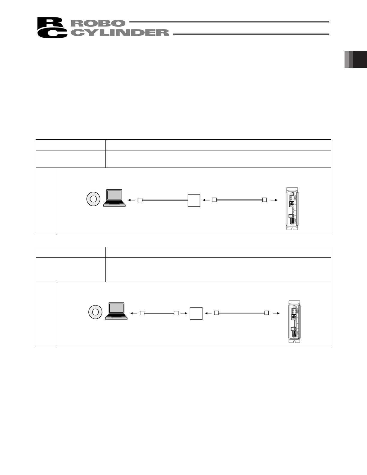
[4] External connection cables (1)
External connection cables vary depending on the PC interface software type.
The types and external connection cables are shown in the table below.
Type External Connection Cable
RCM-101-MW RS232C conversion unit (RCB-CV-MW): 1 cable
Communication cable (CB-RCA-SIO050): 1 cable
*1
(1)
Compatible controller
1. Preparation Before Use
PCON, etc.
Connection
Configuration
Type External Connection Cable
RCM-101-USB USB conversion unit (RCB-CV-USB): 1 cable
Communication cable (CB-RCA-SIO050): 1 cable
USB cable (CB-SEL-USB030): 1 cable
Connection
Configuration
*1 ROBONET Gateway Parameter Setting Tool is stored in the CD-ROM.
Refer to ROBONET Operation Manual for the how to use the tool.
RS232C conversion unit
RCB-CV-MW
USB conversion unit
(RCB-CV-USB)
USB cable
CB-SEL-USB030
Communication cable:
CB-RCA-SIO050
Communication cable
CB-RCA-SIO050
Compatible controller
PCON, etc.
1
Page 14

1.2 Operating Environment
You need the following environment to run this software.
Applicable operating systems
Model number Supported operating systems
1. Preparation Before Use
Computer Personal computer running an applicable operating system (Windows)
Keyboard Keyboard compatible with a personal computer running an applicable
Memory Enough memory needed to run an applicable operating system
Display XGA or higher
Pointing device Mouse and other compatible driver
Memory-medium reading drive CD-ROM drive
Hard disk Hard disk with at least 20 MB of free space
Serial port
RS232C
(compatible with EIA-S74)
RCM-101-MW Windows 2000 SP4 or later, Windows XP SP2 or
later*1, Windows Vista *2, Windows 7
RCM-101-USB Windows 2000 SP4 or later, Windows XP SP2 or
*1
later
, Windows Vista *2, Windows 7
*2
*2
*1 Supported by software version V7.00.00.00 or later
*2 Supported by software version V9.00.00.00 or later
Applicable for 32 bit and 64 bit versions of the OS.
operating system (Windows)
(Windows)
(This software must be installed on the hard disk.)
An applicable serial port is required if the model number of your PC
software is as follows:
Model number: RCM-101-MW
USB port An applicable serial port is required if the model number of your PC
software is as follows:
Model number: RCM-101-USB
2
Page 15
1.3 Installing the Software
This software is run from the hard disk. This section explains how to install the software.
1.3.1 How to Install the PC Interface Software for RC
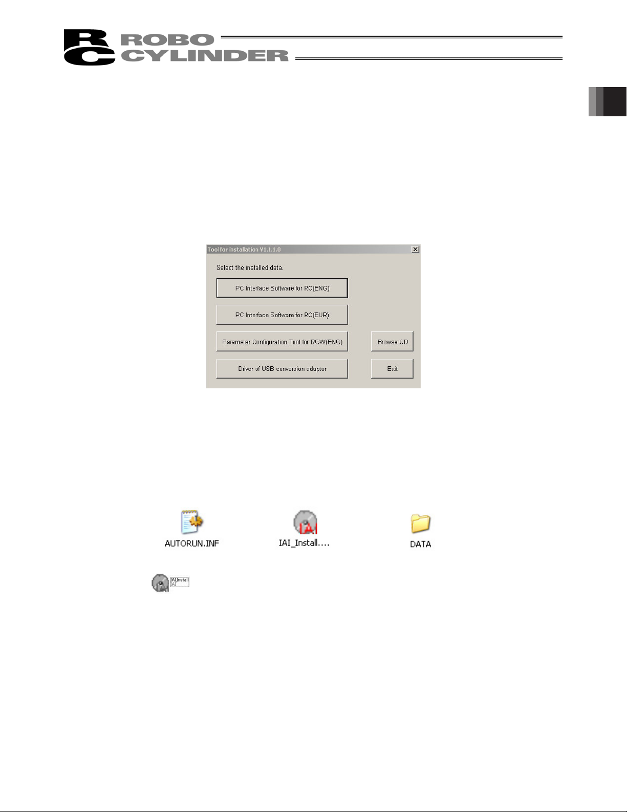
[1] Insert the CD-Rom containing this software into your CD-ROM drive.
[2] The installed data selection window (Fig. 1.1) will be displayed.
Select the version you wish to install from these choices: PC Interface Software for RC (ENG) and PC
Interface Software for RC (EUR). Then click the corresponding button to begin the installation. (Some
items are not indicated depending on the version.)
Fig. 1.1 Installed Data Selection Window
(The displayed window may vary depending on the version or other factor.)
1. Preparation Before Use
* What to do when the Installed Data Selection window (Fig. 1.1) does not appear
If the Installed Data Selection window (Fig. 1.1) does not appear after inserting the CD-ROM, follow the
procedure below to display the Installed Data Selection window.
a. Use Explorer, etc., to display a list of folders and files in the CD-ROM.
The window should display the icons shown in Fig. 1.2.
Fig. 1.2 Icons
b. Double-click among the icons displayed. The Installed Data Selection window (Fig. 1.1) will
appear.
3
Page 16
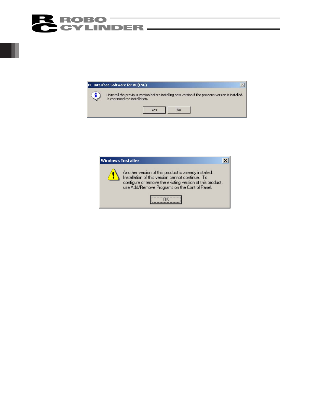
[3] A previous version install check window (Fig. 1.3) is displayed.
Click Yes if no previous version has been installed.
Click No if any previous version has been installed.
Installation is interrupted, then uninstall using the Program add/remove icon on the control panel.
1. Preparation Before Use
If the installer still detects that a previous version is installed after you have clicked Yes, the previous
version detection window (Fig. 1.4) appears. If this window appears, uninstall the previous version and
then repeat the installation process from the beginning.
* How to uninstall is described at the end of how to install PC Interface Software for RC. Refer to it.
Fig. 1.3 Previous Version Install Check Window
Fig. 1.4 Previous Version Install Check Window
4
Page 17

[4] The installation window (Fig. 1.5) for PC Interface Software for RC
Click Next.
Fig. 1.5 Installation Window
[5] Customer information register window (Fig. 1.6) is displayed. Enter customer information and click Next.
1. Preparation Before Use
Fig. 1.6 Customer Information Registration
5
Page 18
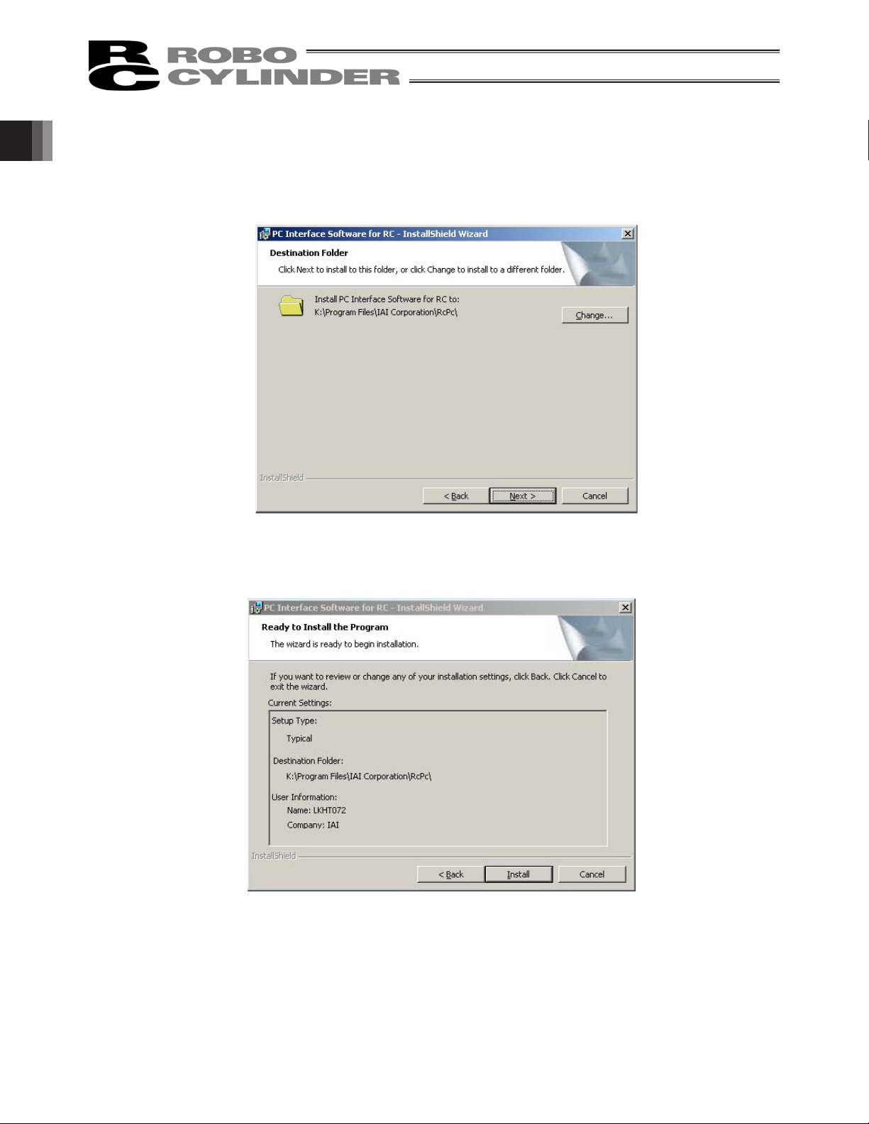
[6] Specify a destination folder to install the PC interface software for RC. (Fig. 1.7)
Normally, you can install it to the default location.
After specifying it, click Next.
1. Preparation Before Use
Fig. 1.7 Specification of Destination Folder
[7] The wizard is ready to begin installation. Clicking Install will begin actual installation.
Fig. 1.8 Installation Preparation
6
Page 19

The window shown in Fig. 1.9 will be displayed during installation.
Fig. 1.9 Installation Progress
[8] When installation is completed, the window shown in Fig. 1.10 will be displayed.
1. Preparation Before Use
Fig. 1.10 Installation Completion
7
Page 20

[9] When the install program is ended, a shortcut in Program o IAI o ROBO Cylinder o PC Interface
Software for RC is displayed on the start menu. This software starts by selecting this item.
[10] Remove the CD-ROM.
* If install is completed with the previous version installed, two shortcuts may be located in Program o IAI o
ROBO Cylinder on the start menu. In this case, only the short cut corresponding to the present version is
deleted when uninstalled. Right click the shortcut for the previous version (PC Interface software for
RC&E-Con) click Delete to manually delete it.
1. Preparation Before Use
Fig. 1.11 Shortcut Delete Window for Previous Version
8
Page 21
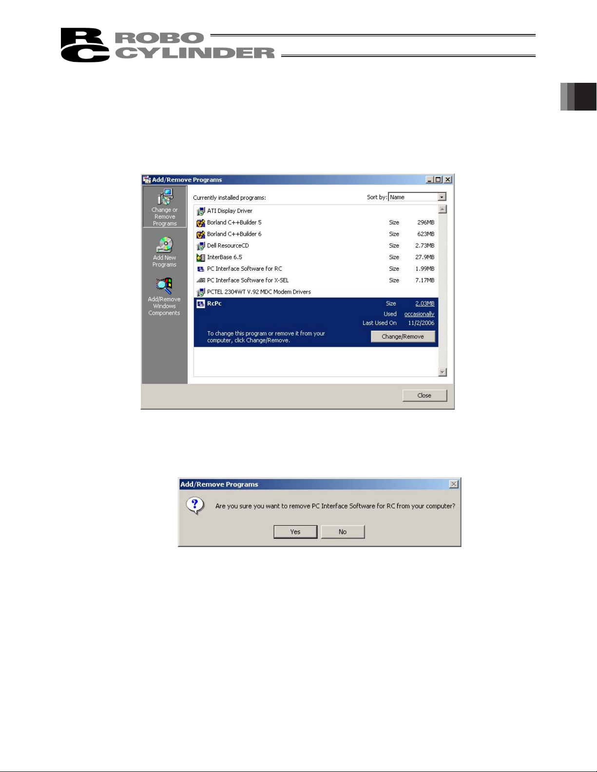
1.3.2 How to Uninstall PC Interface Software for RC
[1] Open the application add and delete window on the control panel.
[2] Select RcPc on the application add and delete window, and click Change/Remove.
1. Preparation Before Use
Fig. 1.12 Application Add and Delete
[3] When a file delete check window (Fig. 1.13) is displayed, click Yes.
Fig. 1.13 File Delete Check
9
Page 22

1.3.3 How to Install the USB Conversion Adapter Driver Software
When a USB port is used, it is required to install USB conversion adapter driver software.
[Compatible software]
RCM-101-USB (with USB conversion adaptor + cable)
(1) Windows XP and Windows 2000
For Windows XP and Windows 2000 follow the steps below to install the software.
[For how to install in Windows 7 and Windows Vista, refer to (2) Windows Vista.]
[1] Insert the CD-ROM of this software into your CD-ROM drive.
1. Preparation Before Use
[2] The installed data selection window (Fig. 1.14) will be displayed.
Click [USB conversion adapter].
Fig. 1.14 Installed Data Selection Window
(The displayed window may vary depending on the version, data in the CD or other factors.)
10
Page 23

[3] You are prompted to set the folder of the copy destination. If you use the displayed folder as it is, click
Copy. To change it, enter it manually or click Browse to set the folder of the copy destination.
On the browse for folder window (Fig. 1.16), click the folder of the copy destination to select it and then
click OK. Once you have clicked OK, the browse for folder window (Fig. 1.16) will disappear and the
selected folder path will be displayed on the window to specify the folder of the copy destination (Fig.
1.15).
Fig. 1.15 Window to Specify Folder of Copy Destination
1. Preparation Before Use
Fig. 1.16 Browse for Folder Window
[4] When the folder of IAI USB (copy data) already exists in the copy destination, you are prompted to
overwrite it.
Click OK to overwrite it, or click Cancel to stop copying.
Fig. 1.17 Overwrite Confirmation Window
[5] The complete window (Fig. 1.18) will be displayed.
Fig. 1.18 Complete Window
11
Page 24
[6] Once the complete window (Fig. 1.18) has been displayed, click OK. The complete window (Fig. 1.18) will
disappear. Then, click Cancel on the window to specify the folder of the copy destination (Fig. 1.15).
The window to specify the folder of the copy destination (Fig. 1.15) will disappear.
Finally, click Exit on the data selection window (Fig. 1.14). The data selection window (Fig. 1.14) will
disappear.
[7] Remove the CD-ROM.
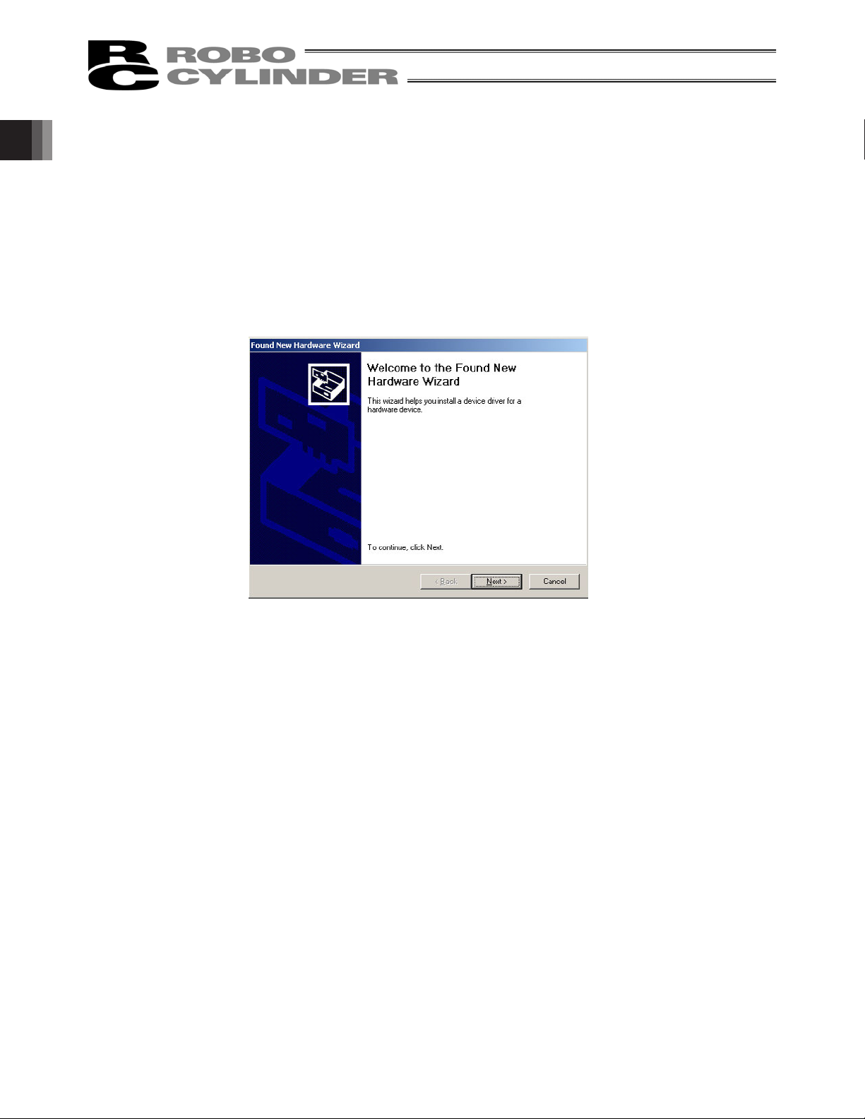
[8] Then, insert the USB conversion adapter (RCB-CV-USB) into the USB port of your PC.
[9] Windows will open the Found New Hardware Wizard.
1. Preparation Before Use
Click Next.
Fig. 1.19 Found New Hardware Wizard Start Window
12
Page 25
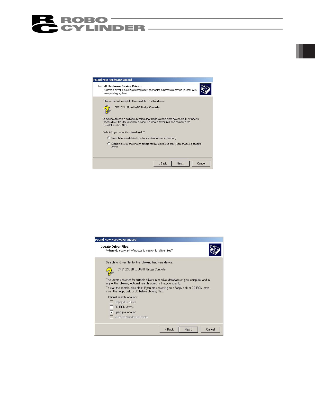
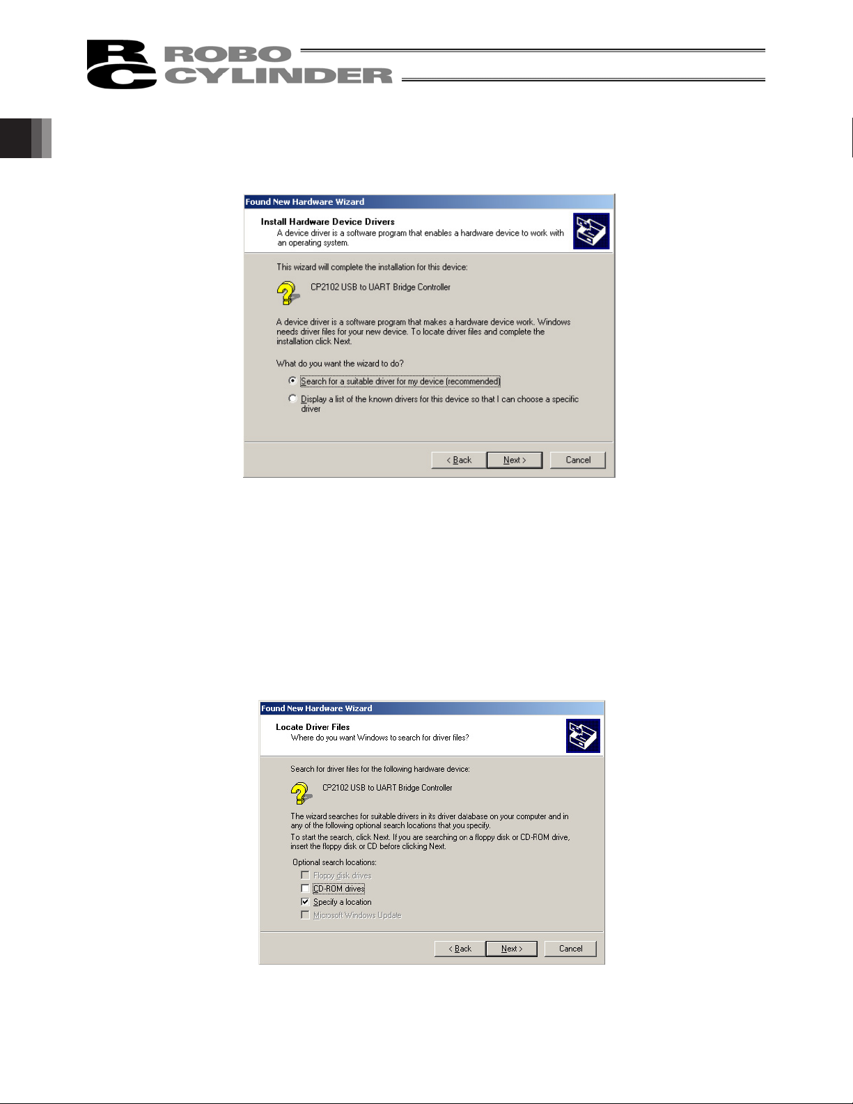
[10] The driver search select window will open.
Check the Search for a suitable driver for my device (recommended).
Click Next.
Fig. 1.20 Driver Search Select Window
1. Preparation Before Use
[11] The locate driver files window will open.
Select Specify a location.
Click Next.
Fig. 1.21 Specify the Locate Driver Files Window
13
Page 26

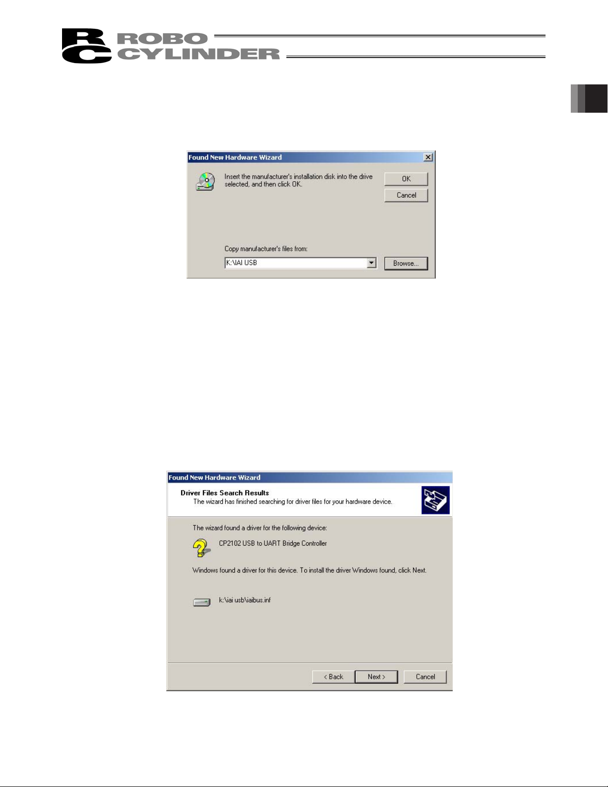
[12] The “Copy manufacturer’s files from:” window will open.
Click Browse and find K: \IAI USB (the folder you have specified in [3] of 1.3.3) and set it.
Click OK.
1. Preparation Before Use
Fig. 1.22 Specify the Copy Manufacturer’s Files from Window
[13] The driver files search results window will open.
Click Next.
Fig. 1.23 Driver Files Search Results Window
14
Page 27
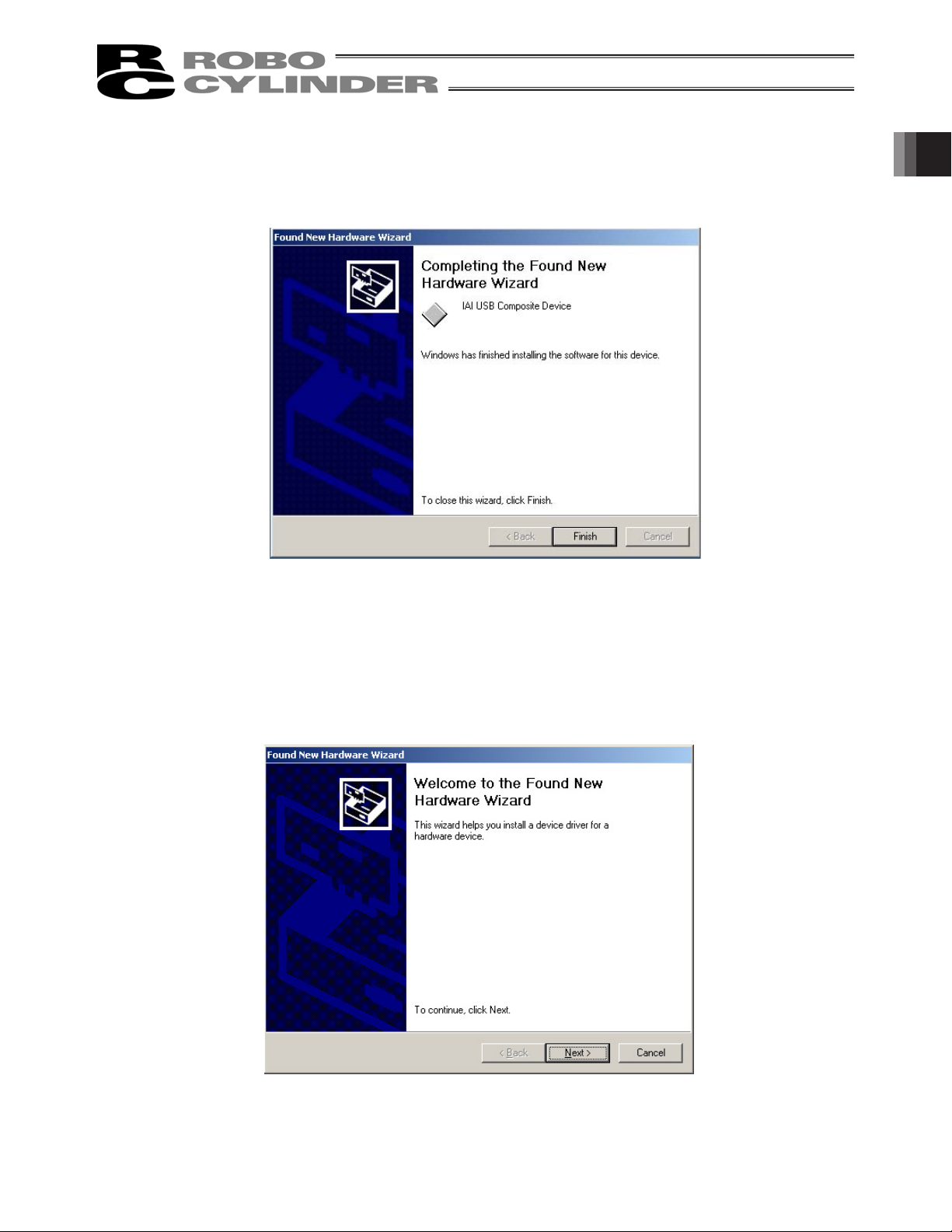
[14] When the IAI USB Composite Device driver installation finish is displayed, the installation of the driver is
completed.
Click Finish.
Fig. 1.24 IAI USB Composite Device Installation Finish Window
1. Preparation Before Use
[15] Subsequently, the found new hardware wizard window will open.
Click Next.
Fig. 1.25 Found New Hardware Wizard Window
15
Page 28
[16] The install hardware device drivers window will open.
Select the Search for a suitable driver for my device recommended.
Click Next.
1. Preparation Before Use
Fig. 1.26 Driver Search Select Window
[17] The locate driver files window will open.
Select Specify a location.
Click Next.
Fig. 1.27 Locate Driver Files Window
16
Page 29
[18] The copy manufacturer’s files from window will open.
Click Browse and find K:\IAI USB (the folder you have specified in [3] of 1.3.3) and set it.
Click OK.
Fig. 1.28 Specify the Copy Manufacturer’s Files from Window
1. Preparation Before Use
[19] The driver files search results window will open.
Click Next.
Fig. 1.29 Driver Files Search Results Window
17
Page 30
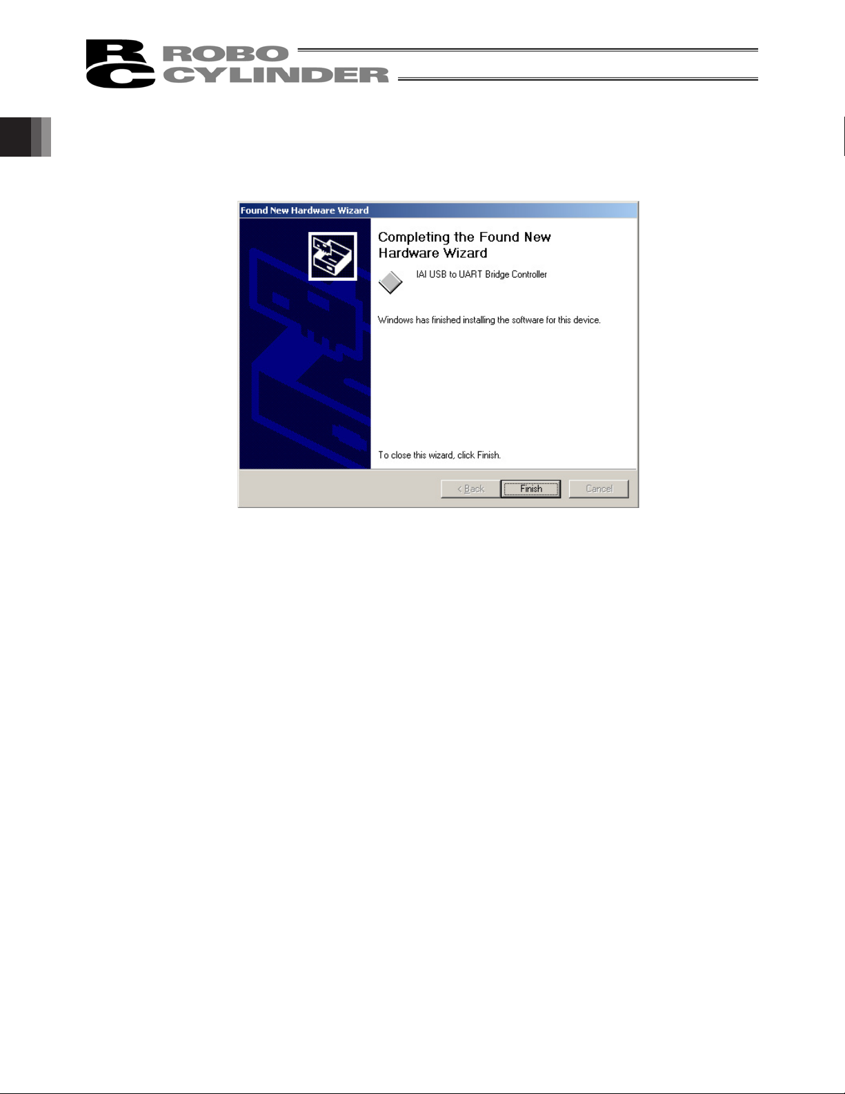
[20] When the IAI USB to UART Bridge Controller driver installation finish window is displayed, the driver
installation is completed.
Click Finish.
1. Preparation Before Use
Fig. 1.30 IAI USB to UART Bridge Controller Installation Finish Window
[21] The installation of all drivers is completed.
18
Page 31

[22] Click Start on the Windows taskbar, Settings, and then Control Panel to open the Control Panel.
Double-click System to open System Properties.
Click the Hardware tab in System.
Click Device Manager in Hardware.
Double-click Ports (COM & LPT) in Device Manager to expand the folder tree.
If there is IAI USB to UART Bridge Controller (COM?) under Ports (COM & LPT) in Device Manager,
the driver has normally been installed and operated.
(Note) The number added to the end of COM? becomes the number of the inserted COM port.
1. Preparation Before Use
Fig. 1.31 Device Manager Window
19
Page 32

(2) Windows 7, Windows Vista
For Windows 7, follow the steps below to install the software.
You shall follow the same steps for Windows Vista.
[1] Insert the CD-ROM of this software into your CD-ROM drive.
[2] Click on USB conversion adapter in the window to select what to install.
[3] A previous version install check window is displayed.
Click Yes if no previous version has been installed.
Click No if any previous version has been installed.
1. Preparation Before Use
Installation is interrupted, then uninstall using the Program add/remove icon on the control panel.
Fig. 1.32 Previous Version Install Check Window
[4] IAI USB to UART Bridge Driver Installer window appears. Click Install.
C: IAI USBv3
Fig. 1.33 IAI USB to UART Bridge Controller Driver Installer Window
20
Page 33

[5] If there is an IAI USB already exists, the Notice display confirmation window will appear. Click Yes.
Fig. 1.34 Notice display confirmation window
[6] Computer restart confirmation window appears. Click Restart Now. Windows will be restarted.
1. Preparation Before Use
Fig. 1.35 Computer Restart Confirmation Window
[7] Connect the PC and USB conversion adapter using a USB cable.
[8] Installation of the driver is complete.
If the installation does not complete, follow the instruction from [9].
21
Page 34

[9] Open Device Manager.
Right-click on CP2102 USB to UART Bridge Controller, and then left-click on Update Driver Software.
1. Preparation Before Use
[10] Update window for the driver software opens. Click on Browse my computer for driver software button
in Update Driver Software window.
Fig. 1.36 Device Manager Window
Fig. 1.37 Update Driver Software Window
22
Page 35

[11] Update window for the driver software opens.
In the box circled in Update Driver Software window, input the directory “C:Program Files\IAI\IAI USBv3”.
Click Next.
C: Program Files\IAI\IAI USBv3
Fig. 1.38 Update Driver Software Window
1. Preparation Before Use
[12] Driver software update complete (IAI USB to UART Bridge Controller) window opens. Click Close in the
Update Driver Software window.
Fig. 1.39 Update Driver Software Complete (IAI USB to UART Bridge Controller) Window
[13] Installation of the driver is complete.
23
Page 36

1.3.4 How to Change the IAI USB COM Port
The COM port set during the installation of the USB conversion adapter driver software can be changed by
following the procedure below:
[1] Click Start on the Windows taskbar, Settings, and then Control Panel to open the Control Panel.
Double-click System to open System Properties.
Click the Hardware tab in System.
Click Device Manager in Hardware.
Double-click Ports (COM & LPT) in Device Manager to expand the folder tree.
[2] Double-click IAI USB to UART Bridge Controller (COM?).
1. Preparation Before Use
(Note) “COM?” indicates the current COM port before change.
IAI USB to UART Bridge
Controller (COM?)
Fig. 1.40 Device Manager Dialog Box
[3] The IAI USB to UART Bridge Controller (COM?) Properties dialog box appears.
Click Advanced... in the properties dialog box.
Fig. 1.41 Properties Dialog Box
24
Page 37

[4] The COM? Port Advanced Settings dialog box appears.
Change the COM port number currently selected under COM Port Number:, to a desired number.
After the COM port number has been changed, click OK.
COM Port Number:
Fig. 1.42 COM? Port Advanced Settings Dialog Box
[5] The COM? Port Advanced Settings dialog box closes.
Click OK in the Properties dialog box (Fig. 1.41), and the COM port will be changed.
[6] Close the Device Manager dialog box and then open it again. You should now see the new COM port
number.
After confirming the new COM port number, close the Device Manager dialog box and all other dialog
boxes currently open.
1. Preparation Before Use
25
Page 38

1.4 Starting the Software
[1] Turn off the power to the controller and PC, and connect the controller to the PC using the standard
RS232C cable or USB cable that comes with the software.
[2] Turn on the power to the controller and PC, and start Windows.
[3] If your controller has a port switch, turn the port switch ON before starting this software.
* This software judges whether the mode is online or offline depending on whether the controller and
personal computer are connected or not. A controller equipped with a PORT switch does not operate in
the online mode even if the port switch of the controller is turned ON after this software is started. In this
case, the online mode is turned on by performing [Reconnect] (Refer to 3.1 (5) [2] [Setting of controller]).
[4] A check for connected axis appears and a check for connected axis is started. (Refer to 2. Checking for
Connected Axes).
1. Preparation Before Use
[In the case of PCON, ACON, SCON, ERC2, ERC3, ROBONET, ASEP, PSEP, DSEP,
MSEP and MSCON]
Before the connected axis is checked, the setting of communication window (Fig. 1.45) appears, but only when
the software is started for the first time after its installation. [Refer to 1.5, “Setting of Communication Window.”]
[5] When a check for the connected axis is completed, the main window is displayed, and at the same time, a
window to select Manual operation mode shown in Fig. 1.43 is displayed.
Select the operation mode according to the purpose and press OK.
Hereinafter, select the operation mode according to the purpose of operation.
Fig. 1.43 Manual Operation Mode Select Window
Select the manual operation mode from the following four choices.
Teach mode 1 (Safety speed effective/PIO start prohibition)
PIO start prohibition: Position data and parameter, etc., are allowed to be written in the controller
and actuator operation is commanded by the PC software (I/O ineffective).
Safety speed effective: Maximum speed becomes safety speed (set by a parameter) regardless of
speed designation of position data.
Teach mode 2 (Safety speed ineffective/ PIO start prohibition)
PIO start prohibition: Position data and parameter, etc., are allowed to be written in the controller
and actuator operation is commanded by the PC software (I/O ineffective).
Safety speed ineffective: Allows operation at the speed set in the speed designation of the position data
table (safety speed or higher).
26
Page 39

Monitor mode 1 (Safety speed effective/PIO start permission)
PIO start permission: Monitoring is only allowed. Position data and parameter, etc., are not allowed
to be written in the controller and actuator operation is not commanded by the
PC Software. Operation command (jog, home return, etc.) cannot be
performed from the PC Interface software.
Safety speed effective: Maximum speed becomes safety speed (set by a parameter) regardless of
speed designation of position data.
Monitor mode 2 (Safety speed ineffective/PIO start permission)
PIO start permission: Monitoring is only allowed. Position data and parameter, etc., are not allowed
to be written in the controller and actuator operation is not commanded by the
PC Software. Operation command (jog, home return, etc.) cannot be
performed from the PC Interface software.
Safety speed ineffective: Allows to operate at a speed (safety speed or higher) as commanded from the
PLC.
If a warning of “Baud rate of personal computer is not supported” is given and connection with the
controller cannot be performed, select other baud rate.
䊶 Click setting of main menu, and select “Application”.
䊶 Change baud rate on the “Setting of application” window (Fig.9.1).
䃂 When PCON, ACON, SCON, MSCON, ERC2 and ERC3 are connected, the operation mode is in
“Safety speed effective (with safety limit speed)” when this software is started. In other words, the
maximum speed attained in any position movement operation performed from the PC software (in the
test operation mode) will correspond to the safety speed set by the applicable parameter. To operate
the actuator with speed commands specifying any speed greater than the safety speed set in the
position data table, you must change the operation mode to “Safety speed ineffective (without safety
limit speed).”
For switching between with safety speed and without safety speed, refer to 3.2, “Operations using
toolbar buttons.”
1. Preparation Before Use
[In the case of RCP, RCS, E-Con, RCP2 and ERC2]
[5] When checking if the connected axis is completed, a warning window is displayed.
When OK is clicked, a main window is displayed.
Fig. 1.44 Warning
27
Page 40

1.5 Setting of communication Window
The “Setting of communication” window (Fig. 1.45) is displayed only at the initial start after the software has
been installed. In this window, setting for communication with the controller is made.
1. Preparation Before Use
[1] Port
From the list, select the serial port to be used to communicate with the controller.
[2] Baud rate
From the list, select the baud rate.
* The baud rate selected here is used only in the communication between this application and controller.
It does not affect the communication speed parameters of the controller.
* If baud rate is not supported by the port selected in [1], an error occurs when connection is checked.
Fig. 1.45 Setting of Communication Window
[3] Last axis No.
Select the axis number of the last axis to be checked for connection.
* Axes of numbers greater than the value selected here will not be checked for connection. Select an
appropriate axis number after checking the axis numbers of the connected axes.
After setting the above items, click the OK button, then checking for connected axes is performed. (From the
next start, checking for connected axes will be automatically performed by this setting.)
* Contents set here can be changed on the setting of application window (Fig. 9.1).
If the Cancel button is clicked, application is ended without performing checking for connected axes (this
setting of communication window will be displayed again.)
28
Page 41

2. Checking for Connected Axes
The software checks for connection of all axes up to the axis specified in the Last Axis NO. box of the “Setting
of communication” window (Fig. 1.45) or “Setting of application” window (Fig. 9.1).
After the check, “(Connecting)” will be shown for those axes whose connection has been confirmed, while “-”
will be shown for all other axes.
Fig. 2.1 Check for Connected Axes Window (Checking for Connection)
2. Checking for Connected Axes
Fig. 2.2 Check for Connected Axes Window (Connection Check Completed)
Check for connected axes can be cancelled by pressing the [ESC] key. (In this case, offline mode is set.)
Connecting a controller whose enable function is enabled
If you have connected a controller whose enable function is enabled by the applicable parameter, a window
appears with the message asking if you want to disable the enable function.
If the enable function remains enabled, the servo cannot be turned ON in the teaching mode.
29
Page 42
3. Main Window
3. Main Window
(1) PCON, ACON, SCON, ROBONET, ASEP, PSEP, DSEP, MSEP, MSCON controllers,
ERC2 and ERC3
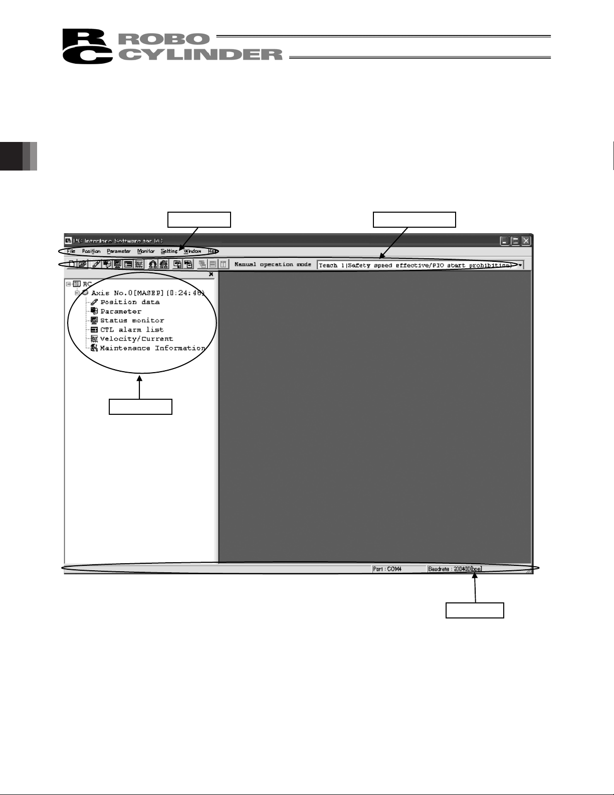
As shown in Fig. 3.1, the main window consists of main menu, toolbar buttons, tree view and status bar. The
tree view on the left side of the window can be displayed by operation of “Window” o “Tree view” on the menu.
(Initial window: Main menu)
Main menu Toolbar buttons
Tree view
Fig. 3.1 Main Window (Online Window)
Status bar
Select each item explained in 3.1, “Operating from the Main Menu” or 3.2, “Operations Using the Toolbar
Buttons” from the main menu in the main window (Fig. 3.1) or by clicking the corresponding tool button.
30
Page 43

(2) RCP, RCS, E-Con, RCP2 controller and ERC
As shown in Fig. 3.2, the main window consists of main menu, toolbar buttons, tree view, and status bar. The
tree view on the left side of the window can be displayed by operation of “Window” o “Tree view” on the menu.
(Initial window: Main menu)
Tree view
Main menu
3. Main Window
Toolbar buttons
Fig. 3.2 Main Window (Online Window)
Select each item explained in 3.1, “Operating from the Main Menu” or 3.2, “Operations Using the Toolbar
Buttons” from the main menu in the main window (Fig. 3.2) or by clicking the corresponding tool button.
31
Page 44

3.1 Operating from the Main Menu
(1) File
[1] [New]
Create new position data.
[2] [Open]
Load position data or parameters from a file.
[3] [Close]
Close the active file.
3. Main Window
[4] [Send to Controller] (Available in the online mode)
[Position Data]
Write position data in a file to the controller.
[Parameter]
Write parameters in a file to the controller.
[5] [Backup] (Available in the online mode)
[Save from Controller to File]
Save all position data and parameters in the controller to a file.
[Send from File to Controller]
Send all position data and parameters in a file to the controller.
[Backup data print]
Print backup data.
The following menus are added from V8.2.0.0.
[Parameter edit]
Editing is available in the parameter edit window from the backup file.
[Position data edit]
Editing is available in the position data edit from the backup file.
[Batch Backup]
The position parameter data of the axes selected from the connected multiple axes can be stored at once
to the individual file.
[Batch Restore]
The position parameter data of the files exist in the selected folders can be transferred to the controller at
once.
[6] [Recently used file]
History of recently read files are displayed, and you can select file name from these to read.
[7] [Exit]
Exit this application.
32
Page 45

(2) Position (Available in the online mode)
[1] [Edit/Teach]
Load position data from the controller for editing or use in teaching.
* In the case of pulse sequence mode of PCON-PL/PO, ACON-PL/PO, SCON-CA, PCON -CA and ERC3
position data cannot be entered. For this reason the simple program line, teach position button, step
move, play button, etc. are not displayed.
[2] [Send to Controller]
Transfer (write) edited position data to the controller.
* In the case of pulse sequence mode of PCON-PL/PO, ACON-PL/PO, SCON-CA, PCON-CA and ERC3
position data cannot be sent to the controller.
Even when you attempt to send position data to the controller, it is not displayed as a selectable
controller on the “select axis number” window.
[3] [Print]
Print the position data you are currently editing.
* In the case of pulse sequence mode of PCON-PL/PO, ACON-PL/PO, SCON-CA, PCON-CA and ERC3
position data cannot be printed.
(3) Parameter (Available in the online mode)
[1] [Edit]
Load parameters from the controller for editing.
3. Main Window
[2] [Send to Controller]
Transfer (write) edited parameter to the controller.
[3] [Print]
Print the parameter you are currently editing.
[4] [SEP Controller Setting Information]
In here, shows the details of the initial settings done to SEP controller.
[5] [Control Parameter Setting]
[Frequency Analysis for Vibration Control]
Calculate the vibration frequency of the load whose vibration you want to suppress, and set appropriate
parameters.
[Refer to 12, “Frequency Analysis for Vibration Control Function.”]
33
Page 46

3. Main Window
(4) Monitor (Available in the online mode)
[1] [Status]
You can check the various statuses of each axis (axis status, internal flags and I/O ports).
[2] [CTL Alarm List]
Display the CTL alarm list window.
[3] [Velocity/Current]
Display the velocity/current monitor window.
* RCP, RCS and E-Con cannot use this function.
Refer to “Supported Models.”
[4] [Servo Monitor]
Display the servo monitor window.
* This window is available only with SCON-CA, PCON-CA, ERC3 (Software Version V8.03.00.00 or later)
and MSCON controllers.
[Refer to 8.4, “Servo Monitor Window.”]
[5] [Maintenance Information]
Display the maintenance information window.
* This window is available only with SCON-CA, PCON-CA, ERC3 (Software Version V8.03.00.00 or later)
and MSCON controllers.
[Refer to 8.5, “Maintenance Information Window.”]
34
Page 47

(5) Setup
[1] [Application Setup]
Set up the application (baud rate and ports).
[Controller Other than ASEP, PSEP, DSEP and MSEP]
You can separately change the system passwords needed to open the position data edit window and
parameter setting window. Note that if the password for the position data edit window is “0000” (factory-set
password), you need not enter any password to open the position data edit window.
[ASEP, PSEP, DSEP and MSEP Controller]
You can change the passwords needed to open the parameter setting window and initial setting window.
With ASEP, PSEP, DSEP and MSEP controllers, the password for the position data edit window is set by
parameter No. 20. Note that if the password for the position data edit window is “0000” (factory-set
password), you need not enter any password to open the position data edit window.
[2] [Controller Setup]
[Reconnect]: Reconnect the axes.
If the software connects to multiple controllers linked by controller link cables, always select Reconnect
after cycling power to a connected controller to which the teaching pendant is not connected directly.
[Disconnect] : Cuts the communication with all the connected axes.
[Assign Axis Number] : Available only for types not equipped with axis number setup rotary
SW.
The last axis number will be the axis number set for the last axis
number* on the setting of application window.
[Reset Software] : Reset (restart) the software.
* RCP, RCS and E-Con cannot reset the software.
[Initial Setting for SEP Controller] : Select the operation pattern of your SEP controller (from PIO patterns
0 to 6) and set the operation mode (single-solenoid, double-solenoid,
etc.), among others.
[Time Setting] : Set the time for SCON-CA, PCON-CA, ERC3 PIO Converter, MSEP
and MSCON.
* Only the time for SCON-CA, PCON-CA and ERC3 PIO Converter
(Software Version V8.03.00.00 or later), MSEP and MSCON can be
set.
[Load Cell Calibration] : Perform the load cell calibration on RCS2-RA13R actuator equipped
with load cell.
[Actuator Replacement] : Reset the counter to 0 for the total travel times and total driving
distance [m] in the maintenance information. Input the password 5119
and press OK.
[Fan Replacement] : Reset the counter to 0 for the total fan driving time [days] in the
maintenance information. Input the password 5119 and press OK.
3. Main Window
35
Page 48

(6) Window
[1] [Cascade]
Rearrange all open windows in such a way that they are cascaded (staggered) on top of each other.
[2] [Tile Vertical]
Rearranges all open windows as vertical tiles.
[3] [Tile Horizontal]
Rearranges all open windows as horizontal tiles.
[4] [Arrange Icons]
Arrange all window icons (minimized windows).
3. Main Window
[5] [Minimize All]
Minimize all open windows.
[6] [Maximize All]
Restore all window icons (minimized windows) to their original size.
[7] [Close All]
Close all the windows that are open.
[8] [Tree View]
Show/hide the tree view (Fig. 3.5).
[9] [Font size]
Change font size on the position data edit window (Fig. 5.5, Fig. 6.12) and the parameter edit window (Fig.
7.7), etc.
Select font size from largest, large, medium, small and smallest.
(7) Help
[1] [Help]
Display the help file.
[2] [About]
Display the version information of this application.
* The menu items shown in gray cannot be selected.
36
Page 49

3.2 Operations Using the Toolbar Buttons
[1] [2] [3] [4][5][6][7] [8][9][10][11]
Fig. 3.3 Toolbar Buttons
[1] New position data
Same as clicking File, pointing to New, and then selecting Position Data.
[2] Open file
Same as clicking File, and then selecting Open.
[3] Edit/teach position data
Same as clicking Position, and then selecting Edit/Teach.
* In the case of pulse sequence mode of PCON-PL/PO, ACON-PL/PO, SCON, PCON-CA and ERC3
position data cannot be entered. For this reason, the JOG window (Fig. 5.7) in which the position input
part, tool buttons and simple program are not displayed is displayed.
(Note) You cannot open the position data edit window and parameter edit window at the same time.
[4] Edit parameters
Same as clicking Parameter, and then selecting Edit.
[5] Monitor
Same as clicking Monitor, and then selecting Status.
[6] CTL alarm list
Display the CTL alarm list window.
Same as clicking Monitor, and then selecting CTL Alarm List.
Content of CTL alarm list is stored by battery backup.
Even if power is turned off, content of controller alarm list is not erased.
(ERC2, ERC3, SCON, ACON, PCON, ASEP, PSEP, DSEP, MSEP, ROBONET and MSCON)
3. Main Window
[7] Display the current/velocity current/velocity monitor window.
Same as clicking Monitor, and then selecting Velocity/Current.
* RCP, RCS and E-Con cannot use this function.
Refer to “Supported Functions.”
[8] Reconnect
Same as clicking Setup, pointing to Controller Setup, and then selecting Reconnect.
[9] Disconnect
Same as clicking Setup, pointing to Controller, and then selecting Disconnect.
[10] Save all data
Same as clicking File, pointing to Backup, and then selecting Save from Controller to File.
[11] Send all data
Same as clicking File, pointing to Backup, and then selecting Send from File to Controller.
* The menu items shown in gray cannot be selected.
37
Page 50

3. Main Window
[12][13][14] [15]
Fig. 3.4 Toolbar Buttons
[12] Cascade windows
Same as clicking Window, and then selecting Cascade.
[13] Tile windows vertically
Same as clicking Window, and then selecting Tile Vertical.
[14] Tile windows horizontally
Same as clicking Window, and then selecting Tile Horizontal.
[15] Select manual operation mode. Select from the following four menus.
* Menus are not displayed in case of RCP, RCS, E-Con, RCP2 controllers and ERC.
Teach mode 1 (Safety speed effective/PIO start prohibition)
PIO start prohibition: Position data and parameter, etc., are allowed to be written in the controller
and actuator operation is commanded by the PC software.
Safety speed effective: Maximum speed becomes safety speed (set by a parameter) regardless of
speed designation of position data.
Teach mode 2 (Safety speed ineffective/ PIO start prohibition)
PIO start prohibition: Position data and parameter, etc., are allowed to be written in the controller
and actuator operation is commanded by the PC software.
Safety speed ineffective: Allows operation at the speed set in the speed designation of the position data
table (safety speed or higher).
Monitor mode 1 (Safety speed effective/PIO start permission)
PIO start permission: Monitoring is only allowed. Position data and parameter, etc., are not allowed
to be written in the controller and actuator operation is not commanded by the
PC Software. Operation command (jog, home return, etc.) cannot be
performed from the PC Interface software.
Safety speed effective: Maximum speed becomes safety speed (set by a parameter) regardless of
speed designation of position data.
Monitor mode 2 (Safety speed ineffective/PIO start permission)
PIO start permission: Monitoring is only allowed. Position data and parameter, etc., are not allowed
to be written in the controller and actuator operation is not commanded by the
PC Software. Operation command (jog, home return, etc.) cannot be
performed from the PC Interface software.
Safety speed ineffective: Allows operation at a speed (safety speed or higher) as commanded from the
PLC.
If the controller has an MANU/AUTO switch, the menus become available when the switch is set to the
MANU.
38
Page 51

3.3 Tree View
From the main menu, click Window, and then select Tree View.
Fig. 3.5 Tree View
[1] Axis No. 0 [PCON-CY]
The axis number of each axis and the corresponding controller model are shown.
A light blue icon is shown if the controller is normal. If the controller is in an error state, a red icon is
shown.
3. Main Window
[2]
(Note) You cannot open the position data edit window and parameter edit window at the same time.
[3]
[4]
[5]
[6]
* The specific tree view will vary depending on the model of the connected controller.
Position data
You can double-click this item to open the position data edit window.
* In the case of pulse sequence mode of PCON-PL/PO, ACON-PL/PO, SCON, PCON-CA and ERC3
position data cannot be entered. For this reason, the JOG window (Fig. 5.7) in which position input
part, tool buttons and simple program line are not displayed is displayed.
Parameter
You can double-click this item to open the parameter edit window.
Status monitor
You can double-click this item to open the status monitor window.
CTL alarm list
You can double-click this item to open the CTL alarm list window.
Velocity/Current
You can double-click this item to open the velocity/current monitor window.
39
Page 52

3.4 Status Bar
[1] [2] [3]
Fig. 3.6 Status Bar
[1] Tool tip
Moving the mouse cursor over a toolbar button will display the tool tip on the button.
[2] Port name
The serial port currently in use is indicated.
3. Main Window
[3] Baud rate
The baud rate (bps) of the current communication is indicated.
40
Page 53

4. Selecting an Axis
To perform any of the following operations, select the axis number of the target axis in the “Select axis number”
window (Fig. 4.1).
[1] Open the position data edit window in the online mode. Refer to 5.1 and 6.2 (Note)
[2] Send position data edited in the offline mode to the controller. Refer to 5.2 and 6.3 (Note)
[3] Open the parameter edit window in the online mode. Refer to 6 (Note)
[4] Send parameters edited in the offline mode to the controller. Refer to 6 (Note)
[5] Collectively save all data from the main window: Refer to 3.1 (Note)
[6] Collectively send all data from the main window: Refer to 3.1 (Note)
[7] Open the status monitor window of the monitor from the main window: Refer to 3.1
[8] Open the CTL alarm list window of the monitor from the main window: Refer to 3.1
[9] Open the velocity/current monitor window of the monitor from the main window: Refer to 3.1
[10] Open the servo monitor window of the monitor from the main window. Refer to 3.1.
[11] Reset the software: Refer to 3.1
[12] Set the time: Refer to 3.1.
[13] Display maintenance information: Refer to 3.1.
Before the software switches to the applicable mode in each of the above operations, the “Select axis number”
window appears.
The axis numbers corresponding to the connected axes are shown in the box under Connected axes.
Move the cursor to the axis you want to operate, click to > select the axis, and then click OK. To select all axes,
click >>, and then click OK.
4. Selecting an Axis
Fig. 4.1 Select Axis Number Window
Note: The axes for which the “Position data edit window” or “Parameter edit window” is currently open in the
online mode are not shown. To select any such axis, close the applicable edit window first.
41
Page 54

5. Editing Position Data on CON Controllers and Older Models
Edit position data online or offline on the following controller series:
CON controllers: ERC2, ERC3, PCON, ACON, SCON, ROBONET and MSCON
Older models: RCP, RCS, E-Con, RCP2, ERC
5.1 Online Mode
This mode reads data from the controller to edit.
For ERC2, ERC3, PCON, ACON, SCON, ROBONET and MSCON Fig. 5.5 is displayed.
However, for pulse sequence mode of the PCON-PL/PO, ACON-PL/PO, SCON, PCON-CA and ERC3
controller, position data cannot be entered.
The JOG window in which the position input part, tool buttons and simple program are not displayed is
displayed. (Fig. 5.7)
For RCP, RCS, E-Con, RCP2 and ERC, Fig. 5.8 is displayed.
Click
Position
In the select axis number window, select the axis number corresponding to the axis whose position data you
want to edit. Refer to 4, “Selecting an Axis.”
If the password is not “0000,” the input password window appears. Enter the applicable password.
5. Editing Position Data on CON Controllers and Older Models
and then select
Edit/Teach
Fig. 5.1 Input Password Window
from the main menu, or click
in the toolbar.
42
Page 55

To change the password, perform the operations explained below.
[How to Set Password for Position Data Edit Window]
[1] From the main menu, click
Click the
Change Password
and then select
Setup
button.
Setting of application
.
Fig. 5.2 Setting of Application Window
[2] Select the Position data edit password, and then click the OKbutton.
Fig. 5.3 Select Password Window
[3] Enter the current password, new password, and new password again (for confirmation), and then click the
button.
OK
Once the new password has been set, you must enter the new password to edit position data.
5. Editing Position Data on CON Controllers and Older Models
Fig. 5.4 System Password Window
43
Page 56

In the position data edit window, you can create position data by “MDI (Mathematical Direct Input),” “Direct
Teaching,” “Jogging” or “Inching” operation.
Created/edited position data will become effective after it has been sent to the controller.
To send position data to the controller, click
or click
in the position data edit window.
Position
from the main menu and then select
Send to Controller
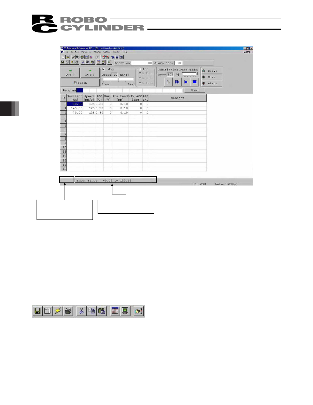
You can also check the teaching positions in two test operation modes: “Positioning” and “Program.”
,
“Modified” is shown if a
change has been made
The input range of each
item is shown.
to the loaded data.
5. Editing Position Data on CON Controllers and Older Models
Fig. 5.5 Position Data Edit Window (Detail Display in Online Mode): PCON, ACON, SCON, ERC2 and
44
* The input range is determined by soft limit + side and
soft limit – side of the parameter.
(Refer to 7, “Editing parameters.”)
ROBONET
(Versions older than V8.00.00.00)
Page 57

Fig. 5.6 Edit position data Window: PCON, ACON, SCON, ERC2, ERC3, ROBONET (Software Version
V8.00.00.00 or later),
MSCON
Fig. 5.7 Jog Window (Online Display) : PCON-PL/PO, ACON-PL/PO, SCON, PCON-CA or ERC3
in Pulse-train Mode
5. Editing Position Data on CON Controllers and Older Models
45
Page 58
“Modified” is shown if a
change has been made
to the loaded data.
Fig. 5.8 Position Data Edit Window (Detail Display in Online Mode): RCP, RCS, E-Con, RCP2 and ERC
* While the position data edit window of a given axis is open in the online mode, the parameter edit window of
the same axis cannot be opened. (You can open the parameter edit window of any other axis.)
* When the MANU operation mode on the main window is monitor mode 1 or monitor mode 2, this online
mode cannot be executed.
Operations of writing into the controller, jog and home return cannot be performed.
5. Editing Position Data on CON Controllers and Older Models
The operating methods of buttons and input controls available in this window are explained below.
The input range of each
item is shown.
(1) Toolbar buttons
[1] [2] [3] [4] [5] [6] [7] [8] [9] [10]
Fig. 5.9 Toolbar in Position Data Edit Window
[1] Save to file
Save data to a file.
[2] Send to controller
Send (write) data to the controller.
46
Page 59

[3] Reload position data
Reload position data from the controller and then refresh the displayed data.
If the position data has been changed in the position data edit window (when “Modified” is shown in the
status bar), clicking this button will display the warning message shown in Fig. 5.10.
* Take note that if you select Yes in this window, data that have been edited but not yet been written to
the controller will be lost.
Fig. 5.10 Warning Message
[4] Print
Output position data to the printer.
Print setting window is displayed. Set top, left and row margins (mm)
and printing orientation, and then print.
[5] Cut
Cut the range of data selected in the position data input area and save
it to the clipboard.
* You can select data in units of rows.
5. Editing Position Data on CON Controllers and Older Models
[6] Copy
Fig. 5.11 Print Setting Window
Copy to the clipboard the range of data selected in the position data input area.
* You can select data in units of rows.
[7] Paste
Paste the data that has been cut or copied from the position data input area, to the selected position.
[8] Switch display
Change the display mode of the position data input area from normal to detail (or vice versa).
(Fig. 5.24, Fig. 5.25) or (Fig. 5.27, Fig. 5.28)
[9] Show status monitor window
Display the status monitor window of the axis you are currently editing.
This window is the same as the one you can open by selecting Status from Monitor in the main menu of
the main window.
[10] Divide position data equally
Clicking this button will display the window shown in Fig. 5.12.
Set appropriate values in Start Position No. and End Position No., select an appropriate option under
Fraction processing, and then click OK. The distance between the specified two position data will be
divided equally. (This function is called “Equal division function”)
When the check box for “Also divide the velocity” is selected, the velocity between the two specified
position tables will also be divided equally. (The “Also divide the velocity” check box is available in Ver.
V6.00.04.00 or later.)
47
Page 60

* Clicking this button while multiple rows are selected in the position data input area will cause the software
to automatically populate the Start Position No. and End Position No. field.
Start Position No.: First position in the selected range
End Position No.: Last position in the selected range
Fig. 5.12 Divide Position Data at Equal Intervals Window
If data has been input between the specified two positions, the warning message in Fig. 5.13 will be displayed.
Fig. 5.13 Warning Message
5. Editing Position Data on CON Controllers and Older Models
The input fields of position data generated by the equal division function, other than Position and Comment, will
be populated by the corresponding values for the position specified in Start Position No. The Comment field will
be cleared.
* The equal division function can also be implemented from the pop-up menu (Fig. 5.14) displayed by
right-clicking the position data input area.
Fig. 5.14 Pop-up Menu
48
Page 61

(2) Current position/alarm code
The current position of the axis you are editing (unit: mm) and the associated alarm code, if any, are shown.
Fig. 5.15 Current Position/Alarm Code
For emergency stop, “Emergency stop” is displayed on the current position and alarm code displaying part.
Fig. 5.16 Emergency Stop Indication
When motor voltage lowers, “Motor volt. low” is displayed on the current position and alarm code displaying
part.
Fig. 5.17 Motor Voltage Low Indication
* When the motor voltage low is displayed, it means a state that the motor drive power is shut off.
(3) Jogging/Inching operation controls
Select Jog or Inc. (by adding a check mark to the corresponding checkbox) and use the Fw (+) Bw (-)
buttons to move the axis.
Select the jogging speed from “1,” “10,” “30,” “50” and “100” [mm/sec] using the track bar.
In the inching mode, select the feed pitch from “0.03,” “0.10” and “0.50” [mm] using the applicable radio button.
A click will move the axis by the specified pitch, while holding down the mouse button will cause the axis to jog
at 1 mm/sec after 2 second. If the mouse button is held continuously, the jogging speed will increase from
“10” to “30” and to “100” [mm/sec] every second.
If home return has been completed, clicking Teach will load the current position to the point data input area.
* In the position data input area, the loaded data will be input to the row where the cursor is located. Check the
cursor position before clicking Teach.
Track bar Checkbox Radio buttons
5. Editing Position Data on CON Controllers and Older Models
Fig. 5.18 Jogging/Inching Operation Controls
49
Page 62

(4) Positioning (test operation mode)
You can move the axis to the position corresponding to the cursor row in the position data input area.
The moving speed is calculated by multiplying the speed set in the position data input area with the speed
factor. (The speed factor can also be set by the track bar.)
Speed factor Track bar
Multiple axes
simultaneous start
Fig. 5.19 Positioning
Clicking
(step) will move the axis by one position, while clicking (continuous move) will cause the axis
to move continuously by looping within the block of specified position data.
Clicking
Clicking
again while the axis is moving continuously will stop the axis when it reaches the next position.
will stop the axis (the axis will start decelerating the moment the button is clicked and continue to
decelerate until it finally stops.)
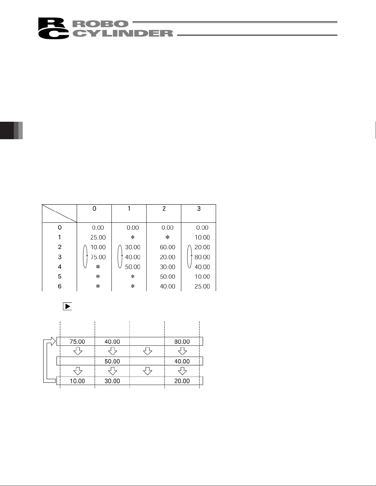
* What is a continuous move?
If a continuous move command is issued at position No. 2 when the position table is set as follows, the actuator
will operate continuously through a group of positions where data is available (= until the position immediately
before one where no data is registered (whose data fields are empty)), starting from the position at which the
command is issued. In this example, the actuator will operate from position No. 2 Æ No. 3 Æ No. 1 Æ No. 2,
and so on.
Position Velocity
5. Editing Position Data on CON Controllers and Older Models
Acceleration
Step, continue and stop
buttons from the left
Deceleration
* If the data loaded from the controller has been changed, write the modified data again to the controller
beforehand.
* While this mode is active, data cannot be entered in the jogging/inching control groups or point data input
area.
Ɣ When PCON, ACON, SCON, MSCON, ERC2 and ERC3 are connected, the maximum speed becomes the
safety speed of 250 mm/sec or less if the MANU operation mode is set to the teach mode 1 (safety speed
effective).
50
Page 63

Simultaneous Movement of Multiple Axes
Multiple axes simultaneous start button
You can use this button to simultaneously move the selected axes, from among the multiple axes currently
connected by link cables.
Click the multiple axes simultaneous start button in the positioning setting area.
Fig. 5.20 Multiple Axes Simultaneous Start Button
The “Start multiple axes simultaneously” window will open.
Axis number Position
Checkbox
5. Editing Position Data on CON Controllers and Older Models
Fig. 5.21 Start Multiple Axes Simultaneously Window
51
Step, continue and stop
buttons from the left
Page 64
Checkbox: The axes with a check mark in this box will move. The selectable checkboxes are
those of axes whose point edit window is currently open.
Axis: Axis number.
Position: Set a position number in one field. This position determines the movement range
for each specified axis based on a routine similar to continuous movement, and the
axis will move over the determined range. All selected axes will move to this
position. (If no position data is set, the axes will not move.)
Location: The current position of each axis is shown.
Step movement button: Clicking this button will move the axes to the next position and complete the
movement.
Continuous move button: Move the axes continuously. If this button is clicked during continuous movement,
the axes will stop moving after they have reached the current positions.
Stop button: Clicking this button will cancel the current movement and stop the axes on the spot.
* Step movement and continuous movement are activated at a speed set with the position data of each axis.
Example of use) When the “Start multiple axes simultaneously” window is set as shown in Fig. 5.21 and
position data for each axis is set as follows
Axis number
Position
Clicking
(continuous movement) will move the actuators as follows.
5. Editing Position Data on CON Controllers and Older Models
Axis number 0 Axis number 1 Axis number 2 Axis number 3
Does not move.
Does not move.
Does not move.
Does not move.
The actuator corresponding to axis number 2 does not move, because its checkbox is not selected.
The actuators do not move if position data is not set for the corresponding axes.
52
After all specified axes have
completed their movement, they will
move to the next positions.
Page 65

(5) Program
Just like positioning, this is also a test operation mode. In the program mode, however, you can set a desired
sequence of movement. In the position number input area, enter position numbers (0 to maximum numbers of
positions) or “R” (a symbol specifying a repeat of the preceding numbers), and then click Start. The stop time
of “T1” to “T5” is able to be input from the Version V8.03.00.00 and later.
Up to 16 steps can be specified, including “R.”
If a blank field exists, all subsequent steps are considered invalid. All steps after “R” are also considered
invalid.
Position number input area Start button
Fig. 5.22 Program Mode
Clicking Start will start the specified movement, and the button text will change to Stop. The button text will
change back to Start when the movement ends or the button is clicked again. The sequence set in the program
mode will not be saved to the controller or a file. (for the versions before V9.00.00.00)
For Version V9.00.00.00 and later, the files can be stored.
The stop time of “T1” to “T5” can be set if clicking on “Stop Time Setting”.
(V8.03.00.00 or later)
5. Editing Position Data on CON Controllers and Older Models
Fig. 5.23 Stop Time Setting
If “Number of Program Execution” is 0, it continuously moves until it stops.
If the number is indicated, the move is executed up to the indicated number.
The remaining times is displayed in Remaining.
53
Page 66

(6) Servo, Home and Alarm buttons
Fig. 5.24 Servo, Home and Alarm Buttons
[1] Servo button
This button lets you turn on/off the servo.
When the servo is on, a blue lamp illuminates on the button.
After home return, you can turn off the servo, move the actuator manually and then click Teach to capture
a desired position.
Note: Closing the software when the servo is off will keep the servo in the off state, thus disabling the PIO
operation.
To reset the servo, restart the software with the controller connected, or reconnect the controller
power.
[2] Home button
This button lets you perform home return.
Once home return is complete, a green lamp will illuminate on the button.
[3] Alarm button
This button lets you reset an alarm.
Note that an alarm can be reset only when the servo is off and the cause of the alarm has been removed.
While an alarm is present, a red lamp remains lit on the button.
5. Editing Position Data on CON Controllers and Older Models
54
Page 67

(7) Position data input area: PCON, ACON, SCON-C, SCON-CA, ERC2, ERC3, ROBONET
and MSCON
Input the position data.
It is normally possible to input five items of Position, Speed, Acceleration (ACC), Deceleration (DCL) and
Comment, however, it becomes further possible to input items of Push, Threshold (LoTh), Positioning Band,
Zone+, Zone-, Acceleration and deceleration (Acc/Dcl) mode, Incremental (ABS/INC), Command (Cmnd)
mode and Stop mode by switching to detailed indication with the Indication switching button
In Version V8.03.00.00, “Command Mode” changes to “Gain Set” and “Vib. Sup. No.” is also added. (Refer to
(8), “Position data input area: SCON-CA, PCON-CA, ERC3 and MSCON.”)
As shown in the table, the zone+, zone-, acceleration and deceleration mode, stop mode are enabled or
disabled depending on the type of controller.
List of ON/OFF of Position Table According to Model
AccDcl Mode Stop Mode
Position Table Zone +/-
Trapezoid S-shape
First-order
Delay
Full Servo
Auto
Servo
OFF
.
Gain Set
Vib. Sup.
No.
5. Editing Position Data on CON Controllers and Older Models
ERC2
ERC2-SE
ERC3
ERC3 PIO Converter
PCON-C/CG/CF
PCON-CA
-CY
-SE
RPCON
ACON-C/CG
-CY
-SE
RACON
SCON-C positioner
{
{
{
{
{
{
{
{
{
{
{
{
{
{
PIO pattern: 3
-
PIO pattern: 3
PIO pattern: 0, 1, 2, 4, 5
PIO pattern: 0, 1, 2, 4, 5
PIO pattern: 0, 1, 2, 4, 5
PIO pattern: 1
-
PIO pattern: 0, 1, 2, 4, 5
PIO pattern: 0, 1, 2, 4, 5
PIO pattern: 1
-
PIO pattern: 0, 1, 2, 4, 5
PIO pattern: 0, 1, 2, 4, 5
{
{
× ×
× ×
{ {
{
{ { { { {
{ { { { {
{
× ×
{ {
{ { { { {
{
{
{
× ×
× ×
× ×
{ {
{
{
{ { { {
{ { { {
{ { {
{ { {
× × ×
× × ×
{ { { {
× ×
× × ×
× ×
× ×
× ×
× ×
× ×
× × ×
× × ×
× ×
× ×
× ×
SCON-CA positioner
MSCON
PIO pattern: 0, 1, 2, 4, 5,
{
{
6, 7
-
{ { { { { {
{ { { { { {
55
Page 68

Fig. 5.25 Position Data Input Area (Normal Mode)
[1] [2] [3] [4] [5] [6] [7] [8] [9] [10] [11] [12] [13]
Fig. 5.26 Position Data Input Area (Detail Mode)
[1] No.: Indicates the position data number.
Warning: In the case of a PCON-C/CG/CF, PCON-CA, ACON-C/CG, SCON, ROBONET, ERC3 PIO
Converter or MSCON (remote I/O mode) controller operating in solenoid mode 2 or
PCON-CY or ACON-CY controller operating in solenoid mode 0, be sure to use absolute
coordinates. If relative coordinates are used, position data errors will occur.
Also note that if relative coordinates are used on any of these controllers operating the
specified push mode, completion of push operation cannot be determined.
5. Editing Position Data on CON Controllers and Older Models
[2] Position: Input the target position to move the actuator to, in [mm].
Absolute Coordinates (Incremental:0) : Input the target location by determining the
Relative Coordinates (Incremental:1) : Input the target location by determining the
[3] Vel: Input the speed at which the actuator will be moved, in [mm/sec].
The initial value will depend on the actuator type.
(Note) For SCON-CA, PCON-CA, ERC3 and MSCON, an alarm will be displayed if the
set value is lower than the minimum velocity.
56
distance between the original point and target
position. No negative value can be input.
distance between the current position and target
position. Any negative value can be input (if
coordinates are in the negative direction).
Page 69

[4] Acc/Dcl: Input the acceleration/deceleration at which the actuator will be moved, in [G].
Basically, use acceleration/deceleration within the catalog rated value range.
The input range allows larger value input than the catalog rated values, on the assumption
that the cycle time will be reduced if the transfer mass is significantly smaller than the rated
value.
Make the numeric value smaller if transferred work part vibrates and causes trouble during
acceleration/deceleration.
Speed
Acceleration
Target
position
Deceleration
Time
Target
position
The acceleration will become sudden if the numeric value is made larger, and it will become
gradual if the numeric value is made smalle
r.
(Note) For SCON-CA, PCON-CA, ERC3 and MSCON, an alarm will be displayed if the set
value exceeds the rated acceleration/deceleration.
Caution: Enter appropriate values for Vel and Acc/Dcl in such a way as to prevent excessive impact or
vibration from being applied to the actuator in consideration of the installation conditions and
the shape of transferred work part by referring to the “List of Actuator Specifications” in the
Appendix of the operation manual for each controller.
Increasing such values largely relates to the transfer mass and the actuator characteristics
vary depending on the model, consult IAI regarding the input-limiting values.
[5] Push: Select the positioning operation or push operation.
The default value is “0.”
0 : Normal positioning operation
Other than 0: Indicates the current-limiting value and indicates the push operation.
5. Editing Position Data on CON Controllers and Older Models
57
Page 70

[6] LoTh : In the case of a SCON-CA and PCON-CF controller, the load output signal (PI0) will be
p
output when the command torque exceeds the value set in the “LoTh” field (%) within
the certification range.
The certification range is set by “Zone+/-.”
Use this signal to determine if a press-fit operation has been successful.
* For details, refer to the operation manual for your PCON-CF controller.
[7] Positioning band : The “positioning operation” and “push operation” have different meanings.
Positioning operation:
It defines the distance to the target position from a position at which the position
complete signal turns ON.
The default value is 0.1 mm.
Timing of position
Standard type
complete signal turning ON
Since increasing the positioning band value
hastens the next sequence operation, it
becomes a factor for cycle time reduction. Set
the optimum value by considering the balance
of the entire equipment.
Positioning band
Target
position
Note that with a PCON-C/CG/CF, PCON-CA, CF ACON-C/CG, SCON, ERC3 PIO Converter or MSCON
(remote I/O mode) controller operating in solenoid mode 2 or PCON-CY or ACON-CY operating in solenoid
mode 1, you should define the band within which the complete signal will turn ON.
PCON-C/CG/CF, PCON-CA, ACON-C/CG,
SCON, ERC3 PIO Converter or MSCON
(remote I/O mode) controller operating in
solenoid mode 2 or PCON-CY or ACON-CY
o
erating in solenoid mode 0
Position complete signal
5. Editing Position Data on CON Controllers and Older Models
Push operation:
It defines the maximum push amount from the target position in the push operation.
Set the positioning band in such a way as to prevent positioning completion before the
actuator contacts work part by considering mechanical variations of work part.
position
ON
Positioning band
Position at which the position complete
signal turns ON when the actuator contacts
work part and push completion is judged
Work
part
Target
Positioning band
(maximum push amount)
Target
position
(Note) For PCON-CA and ERC3, a smaller value than the minimum positioning band width
cannot be set.
58
Page 71

[8] Zone +: It defines the zone where the zone output signal of the standard type turns ON.
[9] Zone -: Individual setting is available for each target position to give flexibility.
[Setting example]
No. Position [mm] Zone+ [mm] Zone- [mm] Note
0 5.00 100.00 0.00 Backward end
1 380.00 400.00 300.00 Forward end
2 200.00 250.00 150.00 Midpoint
Movement command to Position No. 0 (backward end)
Backward
Zone output signal
Home
end
Movement command to Position No. 1 (forward end)
Zone output signal
Movement command to Position No. 2 (midpoint)
Zone output signal
Midpoint
Forward
end
5. Editing Position Data on CON Controllers and Older Models
+ side limit
59
Page 72

[10] Acc/Dcl Mode:
It defines the acceleration/deceleration characteristics.
The default value is 0.
0: Trapezoid pattern
1: S-shaped motion
2: First-order delay filter
Trapezoid pattern
Speed
Acceleration
* Set the acceleration and deceleration in the “Acc” and “Dcl” fields of the position table.
S-shaped motion
A curve, which is gradual at the beginning of acceleration but rises sharply halfway, is
drawn.
Use it in the applications for which you want to set the acceleration/deceleration high due to
cycle time requirement but desire a gradual curve at the beginning of movement or
immediately before stop.
Speed
* Set the degree of the S-shaped motion with the parameter No. 56 [S-shaped motion ratio
setting]. The setting unit is % and the setting range is between 0 and 100.
(The above is the image graph when 100% setting is made.)
If “0” is set, the S-shaped motion becomes invalid.
However, it will not be reflected in jogging/increment movement by PC or Teaching
Pendant operation.
(Note) It cannot be set for the ERC2, PCON-C or RPCON controller. The parameter No. 56 is reserved.
5. Editing Position Data on CON Controllers and Older Models
Deceleration
Time
Time
60
Page 73

First-order delay filter
More gradual acceleration/deceleration curves are drawn than the linear
acceleration/deceleration (trapezoid pattern).
Use this in the applications by giving micro vibrations to work part during
acceleration/deceleration not desired.
Speed
* Set the degree of the first-order lag with the parameter No. 55 (constant for the position
command first-order filtering). The setting unit is 0.1 msec and the setting range is
between 0.0 and 100.0.
If “0” is set, the first-lag filter will become invalid.
However, it will not be reflected in jogging/increment movement by PC or Teaching
Pendant operation.
(Note) It cannot be set for the ERC2, PCON or RPCON controller. The parameter No. 55
is reserved.
[11] ABS/INC: Select either the absolute or incremental positioning.
The factory setting is 0.
0: Absolute positioning
1: Incremental positioning
Time
5. Editing Position Data on CON Controllers and Older Models
Warning: In the case of a PCON-C/CG, PCON-CA, ACON-C/CG, SCON, ERC3 PIO
Converter or MSCON (remote I/O mode) controller operating in solenoid
mode 2 or PCON-CY or ACON-CY controller operating in solenoid mode 0, be
sure to use absolute coordinates. If relative coordinates are used, position
data errors will occur.
[12] Cmnd Mode: This field is invalid.
The factory setting is 0.
61
Page 74

[13] Stop Mode: It defines the power saving method on standby after completion of positioning to the target
position set in the “Position” field of the position number.
0: No power saving method * The default setting is 0 (none).
1: Auto servo OFF method. Delay time defined with the parameter No. 36
2: Auto servo OFF method. Delay time defined with the parameter No. 37
3: Auto servo OFF method. Delay time defined with the parameter No. 38
4: Full servo control method
Full servo control method
The holding current can be reduced by servo-controlling the pulse motor.
The degree of reduction varies depending on the actuator model, load condition, etc., but the
holding current decreases approximately by a factor of 1/2 to 1/4.
No displacement occurs since this method maintains the servo ON status.
The actual holding current can be checked on the monitoring window of PC software.
Auto servo OFF method
When a given length of time has elapsed after completion of positioning, the servo OFF status is
automatically entered.
(Since the holding current does not flow, the power consumption can be saved by the same
amount.)
When a movement command is subsequently given from PLC, the status returns to the servo ON
and the actuator starts to move.
Movement
command
Servo status
Servo ON status
Actuator movement
Target position
5. Editing Position Data on CON Controllers and Older Models
Auto servo OFF
(Green LED flashing)
T: Delay time (sec) until the servo OFF
status is entered after completion of
positioning
It is set with the parameter.
62
Page 75

(8) Position data input area
On the SCON-CA (Software Version V8.00.00.00 or later) and MSCON, the following input items have been
changed or added.
These items are effective only on SCON-CA and MSCON controllers:
[1] Gain Set “Cmnd Mode” has been changed to “Gain Set.”
[2] Vib. Sup. No. “Vib. Sup. No.” has been added.
(Note) For PCON, ACON, SCON, ERC2 and ROBONET as well as SCON-CA and MSCON, Version
V8.00.00.00 and later show the following screen display.
[1] [2]
Fig. 5.27
The changed/added items are explained below.
[1] Gain Set ···········Six parameters needed to adjust the servo gain are put together as one set. Four different
sets can be registered, so you can switch the servo gain for each positioning operation.
[Parameters constituting one set]
• Servo gain number (position gain)
• Position feed-forward gain
• Speed loop proportional gain
• Speed loop integral gain
• Torque filter time constant
• Current control band number
Setting Operation after completion of position Parameter number
0 Gain set 0 7, 71, 31 to 33, 54
1 Gain set 1 120 to125
2 Gain set 2 126 to131
3 Gain set 3 132 to137
5. Editing Position Data on CON Controllers and Older Models
63
Page 76

[2] Vib. Sup. No.······You can suppress the vibration (resonance) of the load installed on the actuator.
Three levels of vibration can be suppressed.
Four parameters are provided for each vibration level, where all four parameters constitute
one set.
Set the position number requiring vibration suppression, and applicable parameter set, in
the position table.
Setting
Suppressing vibration frequency
(characteristic vibration frequency)
Parameter number
0 Normal position control (No control) –
1
2
3
Parameter set for vibration suppression
control 1
Parameter set for vibration suppression
control 2
Parameter set for vibration suppression
control 3
97 to 100
101 to 104
105 to 108
Warning: (1) Vibration frequencies that can be controlled (target characteristic vibration frequencies)
are from 0.5 Hz to 30 Hz.
(2) Only the vibration of the load induced by the actuator connected to this controller is
suppressed. No other vibration can be controlled.
(3) Vibration can be suppressed only in the same direction as the moving direction of the
actuator. Vibration in no other direction can be controlled.
(4) Vibration cannot be suppressed during home return or push-motion operation.
(5) This function is not available in the pulse-train input mode.
(6) When the set characteristic vibration frequency is low, the cycle time may become
longer. As a guide, the positioning settling time becomes 150 ms or longer when the
characteristic vibration frequency is approx. 6 Hz or below.
5. Editing Position Data on CON Controllers and Older Models
64
Page 77

(9) Position data input area: RCP, RCS, E-Con, RCP2 and ERC
Enter position data in this area.
It is normally possible to input four items of “Position,” “Speed,” “ACC” and “Comment,” however, it becomes
further possible to input items of “Push,” “Pos. band,” “MAX ACC,” “ABS INC” by switching to detailed
indication with the “Indication switching” button
Fig. 5.28 Position Data Input Area (Normal Mode)
[1] [2] [3] [4] [5] [6] [7] [8]
.
5. Editing Position Data on CON Controllers and Older Models
Fig. 5.29 Position Data Input Area (Detail Mode)
[1] No.: Shows position data No.
[2] Position: The desired move location from home in millimeters.
Absolute Positioning: (Incremental:0) Moves the actuator to the desired location in
reference to the home location. Inputting negative
values is not possible.
Relative Positioning: (Incremental:1) Moves the actuator to the desired position in
reference to the current position. Inputting negatives
values is possible. (during negative direction of the
display coordinate)
Caution: There are cases when the input value may be rounded off to the least common denominator
multiple of the controller. (when data is acquired from the controller).
65
Page 78

[3] Vel: The speed when moving the actuator (mm/sec).
The default value will depend on the actuator type.
[4] Acc/Dcl: The acceleration/deceleration setting for the move to the corresponding position (in G’s).
The default value will depend on the actuator type.
[5] Push: Selects the positioning mode or push mode.
The default value is set as 0.
0: Positioning Mode (normal movement)
Besides 0: Push Mode (%)
In the case of push mode, data number is the motor current limiting value during push.
Uses a value that matches the actuator type with a maximum value of 70%.
[6] Positioning band :
In positioning mode, the position complete detection band (distance to the target position).
The distance to the target position refers to the distance before the value entered here
reaches the target position and the position complete signal is output once the actuator
enters that range.
The default value will depend on the actuator type. (see diagram A)
The push mode uses the maximum push amount (distance from the target position). [mm]
(see diagram B)
When the push direction is negative direction of display coordinates, a “minus” sign should
be placed in the input value.
[5] When push = 0
[1] Distance up to the position
Speed
Transfer distance Transfer distance
Diagram A Diagram B
[6] Positioning band [6] Positioning band
5. Editing Position Data on CON Controllers and Older Models
[5] When push z 0
[1] Distance up to the position
Speed
66
Page 79
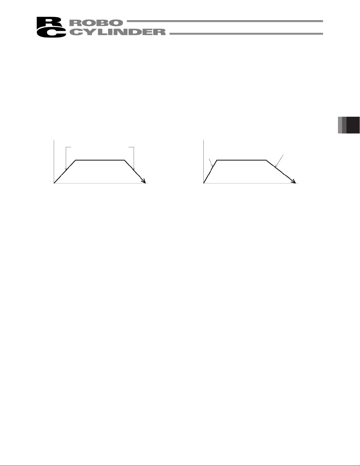
[7] MAX Acceleration:
Selects either the assigned acceleration or the maximum acceleration. Inputs are either 1
or 0. The default value is set as 0.
0: Assigned acceleration
1: Maximum acceleration
The value placed in [4] will be used as the actual acceleration value and
deceleration value.
This will automatically utilize the maximum acceleration matched to the load.
Deceleration remains as the assigned value in [4].
[7] When acceleration only MAX = 0
[4] The value set in
acceleration/deceleration
Speed
Transfer
distance
[7] When acceleration only MAX = 1
The maximum acceleration
Speed
matches the load
[8] ABS/INC Select either the absolute or incremental positioning.
0: Absolute positioning
1: Incremental positioning
5. Editing Position Data on CON Controllers and Older Models
[4] The value set in
acceleration/deceleration
Transfer
distance
67
Page 80

5.2 Offline Mode
When editing data after creating new data or loading data from a file, you are editing the data in the offline
mode.
In this mode, the window controls relating to axis operation are grayed out, and only the toolbar buttons and
position data input area become active. Items that cannot be operated offline are grayed out.
5.2.1 Creating New Position Data
To create new position data, click File from the main menu, and then select New.
[1] When the position data format selection window appears, select the controller whose position data you
want to create, and then click OK.
Fig. 5.30 Position Data Format Selection Window
[2] The position data input window appears.
Enter position data in the position data input area.
Tool buttons
5. Editing Position Data on CON Controllers and Older Models
Fig. 5.31 Position Data Edit Window (Offline Mode – New)
Position data input area
68
Page 81

[3] The created position data can be saved to a file or sent to the connected controller.
(Saving the position data to a file)
To save the position data to a file, click the tool button .
The save as window appears.
Enter a desired file name and click the Save button, and the position data will be saved to a file under the
specified name.
Fig. 5.32 Save As Window
5. Editing Position Data on CON Controllers and Older Models
(Sending the position data to the connected controller)
Connect the controller and PC.
Click Position and select Send to Controller, or click the tool button .
When the axis selection window appears, select the axis number of the controller to send the position data to.
(Refer to 4, “Selecting an Axis.”)
* “Comments” can be saved only to files. They cannot be saved to controllers.
69
Page 82

5.2.2 Reading a File
To read position data from a file, click File and then select Open to open the “Open” window. Alternatively, you
can click File, point to Send to Controller and then select Position to open the “Open” window.
Select folder in which
Saved file name
position data is saved.
Select controller.
Fig. 5.33 “Open” Window
Select (click) “File name” you want to open, and click Open on the “Open” window, then the position data edit
window is displayed.
Position data can be edited offline.
5. Editing Position Data on CON Controllers and Older Models
Tool buttons
Position data input area
Fig. 5.34 Position Data Edit Window (Offline Mode)
70
Page 83

The edited position data can be saved to a file or sent to the connected controller.
(Saving the position data to a file)
To save the position data to a file, click the tool button .
The save as window appears.
Enter a desired file name and click the Save button, and the position data will be saved to a file under the
specified name.
Fig. 5.35 Save As Window
(Sending the position data to the connected controller)
Connect the controller and PC.
Click Position and select Send to Controller, or click the tool button .
When the axis selection window appears, select the axis number of the controller to send the position data to.
(Refer to 4, “Selecting an Axis.”)
5. Editing Position Data on CON Controllers and Older Models
* “Comments” can be saved only to files. They cannot be saved to controllers.
71
Page 84

6. Initial Setting and Position Data Editing for SEP Controllers
SEP controllers: ASEP, PSEP, DSEP and MSEP
6.1 Initial Setting
Select a desired operation pattern (PIO pattern) (from 0 to 5) and set the necessary operation parameters
(such as selecting the single-solenoid or double-solenoid mode).
(Note) For Fieldbus Type MSEP Controllers, Positioner Mode of Operation Pattern (PIO Pattern) 6 can be
selected. The initial setting is not necessary if Positioner Mode is selected.
Click Setup from the main menu, point to Controller Setup, and then select Initial Setting for SEP
Controller.
If the input password window appears, enter the password.
* On the versions V7.00.03.00 or later, the default password is “0000”, so the input password window will not
appear.
* On the versions V7.00.01.00/V7.00.02.00, the default password is “5119.” Enter “5119” and click the OK
button.
Fig. 6.1 Input Password Window
To change the password, perform the operations explained below.
6. Initial Setting and Position Data Editing for SEP Controllers
72
Page 85

[How to Set Initial Password]
* The password should be the same as the one used for editing parameters.
When the password set here is changed, the parameter edit password will also change to the new password.
[1] From the main menu, click
Click the
Change Password
Setting
and then select
button.
Application
.
Fig. 6.2 Setting of Application Window
[2] Enter the current password, (the default password is “0000” for Version V7.00.03.00 or later, or "5119" for
Version V7.00.01.00/V7.00.02.00), new password, and new password again (for confirmation), and then
click the
OK
button.
6. Initial Setting and Position Data Editing for SEP Controllers
Fig. 6.3 System Password Window
Select a desired operation pattern in the IO pattern select window, and then click OK.
(Note) When connected to MSEP Controllers, 6: Positioner Mode is displayed. If 6: Positioner Mode is
selected, it is not necessary to have the initial setting process. The initial setting window would not
appear.
Fig. 6.4 IO Pattern Select Window
73
Page 86

In the initial setting for SEP controller window, set the necessary operation parameters (such as selecting the
single-solenoid or double-solenoid mode), and then click OK.
The operation parameters to be set vary depending on the operation pattern (PIO pattern). Those parameters
that need not be set are grayed out.
In the confirmation window for restarting the controller (resetting the software), click Yes.
6. Initial Setting and Position Data Editing for SEP Controllers
If the actuator servo is currently ON, a warning window appears with the message saying that you must turn
OFF the servo. Click Yes.
Fig. 6.5 Initial Setting for SEP Controller Window
Fig. 6.6 Confirmation Window for Restarting Controller
Fig. 6.7 Warning Window
The controller will be restarted and the operation parameters you have set will be applied to the controller.
74
Page 87

Six types of operation patterns (PIO patterns) are available on ASEP, PSEP, DSEP and MSEP controllers.
A
r
A
r
A
r
A
r
A
A
A
A
Set each item according to the selected operation pattern (PIO pattern).
(Note) For MSEP Controllers, Positioner Mode of Operation Pattern (PIO Pattern) 6 can be selected in addition
to the 6 types. The initial setting is not necessary if Positioner Mode is selected.
Operation pattern
Equivalent air cylinder circuits are shown for your reference.
Operation pattern Description
PIO pattern 0
Single solenoid type
(Standard movement
between 2 points)
The actuator can be moved
between two points using the
same control you normally use
with an air cylinder.
The target position (forward end,
backward end) can be set.
The travel speed and
acceleration/deceleration can be
specified.
Push-motion operation can also be
performed.
Motorized cylinder connection
method
Motorized cylinder
Backward end
position detection
signal (LS0)
Forward end position
detection signal (LS1)
Movement signal
(STO)
SEP,
PSEP,
DSEP,
MSEP
Dedicated
cable
Air cylinder circuit (reference)
ir cylinde
Backward end
position detection
signal (LS0)
Forward end position
detection signal (LS1)
Movement signal
Solenoid
(STO)
Solenoid
Spring
P (Air)
6. Initial Setting and Position Data Editing for SEP Controllers
PIO pattern 0
Double solenoid type
(Standard movement
between 2 points)
PIO pattern 1
Single solenoid type
(Movement between
two points)
(Change travel speed)
PIO pattern 1
Double solenoid type
(Movement between
two points)
(Change travel speed)
The actuator can be moved
between two points using the
same control you normally use
with an air cylinder.
The speed can be changed during
movement.
The target position (forward end,
backward end) can be set.
The travel speed and
acceleration/deceleration can be
specified.
Push-motion operation can also be
performed.
Backward end
position detection
signal (LS0)
Forward end position
detection signal (LS1)
Forward end
movement signal (ST1)
Backward end
movement signal (ST0)
Backward end
position detection
signal (LS0)
Forward end position
detection signal (LS1)
Movement signal
Travel speed switching
signal (SPDC)
Backward end
position detection
signal (LS0)
Forward end position
detection signal (LS1)
Forward end
movement signal (ST1)
Backward end
movement signal (ST0)
Travel speed switching
signal (SPDC)
Motorized cylinder
SEP,
PSEP,
DSEP,
MSEP
Motorized cylinder
SEP,
PSEP,
DSEP,
MSEP
Motorized cylinder
SEP,
PSEP,
DSEP,
MSEP
Dedicated
cable
Dedicated
cable
Dedicated
cable
Backward end
position detection
signal (LS0)
Forward end position
detection signal (LS1)
Forward end
movement signal (ST1)
Backward end
movement signal (ST0)
Backward end
position detection
signal (LS0)
Forward end position
detection signal (LS1)
Movement signal
Travel speed switching
signal (SPDC)
Backward end
position detection
signal (LS0)
Forward end position
detection signal (LS1)
Forward end
movement signal (ST1)
Backward end
movement signal (ST0)
Travel speed switching
signal (SPDC)
ir cylinde
ir cylinde
ir cylinde
Solenoid
Solenoid
Solenoid
Solenoid
(Air)
(Air)
Solenoid
(Air)
(Note) The air cylinder circuits are drawn with signal symbols corresponding to those used by ASEP,
PSEP, DSEP and MSEP controllers.
For details on signal symbols, refer to “ASEP/PSEP/DSEP Operation Manual” and “MSEP
Operation Manual”.
75
Page 88
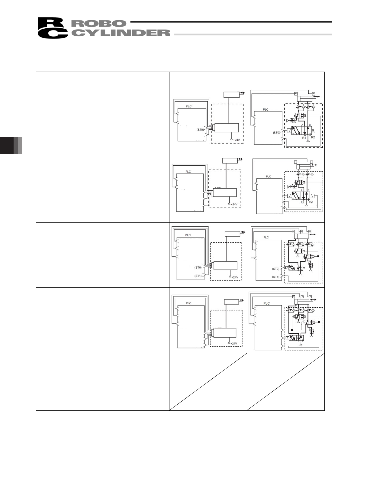
Operation pattern Description
A
r
A
r
A
r
A
r
t
t
A
A
A
A
PIO pattern 2
Single solenoid type
(Movement between two
points)
(Position data change)
The actuator can be moved
between two points using the
same control you normally use
with an air cylinder.
You can switch between
positioning operation and
push-motion operation during
operation.
The target position (forward end,
backward end) can be set.
The travel speed and
PIO pattern 2
Double solenoid type
(Movement between two
points)
acceleration/deceleration can be
specified.
Push-motion operation can also
be performed.
(Position data change)
Operation pattern
Equivalent air cylinder circuits are shown for your reference.
Motorized cylinder connection
method
Motorized cylinder
Backward end
position detection
signal (LS0)
Forward end position
detection signal (LS1)
Movement signal
Target position
switching signal (CN1)
Backward end
position detection
signal (LS0)
Forward end position
detection signal (LS1)
Forward end
movement signal (ST1)
Backward end
movement signal (ST0)
Target position
switching signal (CN1)
SEP,
PSEP,
DSEP,
MSEP
Motorized cylinder
SEP,
PSEP,
DSEP,
MSEP
Dedicated
cable
Dedicated
cable
Air cylinder circuit (reference)
ir cylinde
Backward end
position detection
signal (LS0)
Forward end position
detection signal (LS1)
Movement signal
Target position
switching signal (CN1)
Backward end
position detection
signal (LS0)
Forward end position
detection signal (LS1)
movement signal (ST1)
Backward end
movement signal (ST0)
Target position
switching signal (CN1)
P (Air)
ir cylinde
P (Air)
Forward end
P (Air)
P (Air)
PIO pattern 3
Single solenoid type
(Movement by 2 inputs
among 3 points)
PIO pattern 4
Double solenoid type
(Movement by 3 inputs
among 3 points)
6. Initial Setting and Position Data Editing for SEP Controllers
PIO pattern 5
(Continuous
back-and-forth
operation)
The actuator can be moved
among three points using the
same control you normally use
with an air cylinder.
The target position (forward end,
backward end) can be set.
The travel speed and
acceleration/deceleration can be
specified.
Push-motion operation can also
Backward end position
detection signal (LS0)
Forward end position
detection signal (LS1)
Midway position
detection signal (LS2)
Movement signal 1
Movement signal 2
SEP,
PSEP,
DSEP,
MSEP
Motorized cylinder
Dedicated
cable
Backward end position
detection signal (LS0)
Forward end position
detection signal (LS1)
Midway position
detection signal (LS2)
Movement signal 1
Movement signal 2
ir cylinde
P (Air)
P (Air)
P (Air)
be performed.
The actuator can be moved
among three points using the
same control you normally use
with an air cylinder.
The target position (forward end,
backward end) can be set.
The travel speed and
acceleration/deceleration can be
specified.
Push-motion operation can also
be performed.
Backward end position
detection signal (LS0)
Forward end position
detection signal (LS1)
Midway position
detection signal (LS2)
Midway point
movement signal (ST2)
Forward end
movement signal (ST1)
Backward end
movement signal (ST0)
SEP,
PSEP,
DSEP,
MSEP
Motorized cylinder
Dedicated
cable
Backward end position
detection signal (LS0)
Forward end position
detection signal (LS1)
Midway position
detection signal (LS2)
Midway point movemen
signal (ST2)
Forward end movemen
signal (ST1)
Backward end
movement signal (ST0)
ir cylinde
P (Air)
P (Air)
P (Air)
The actuator moves back and forth
between the two points of forward
end and backward end.
The target position (forward end,
backward end) can be set.
The travel speed and
acceleration/deceleration can be
specified.
Push-motion operation can also
be performed.
(Note) The air cylinder circuits are drawn with signal symbols corresponding to those used by ASEP,
PSEP, DSEP and MSEP controllers.
For details on signal symbols, refer to “ASEP/PSEP/DSEP Operation Manual” and “MSEP
Operation Manual”.
76
Page 89

[Types of Operation Parameters]
y Solenoid
Select either the single-solenoid operation mode or double-solenoid operation mode.
y Servo control
Select whether or not to use servo control (IN3 input signal SON (servo ON/OFF control)).
y Stop signal
Select whether or not to use the pause signal *STP (input to IN2) when the single-solenoid type and
operation pattern 5 are selected.
y Input signal mode
Select continuous current flow (level) or instantaneous current flow (edge) as the double-solenoid ON
condition when the double-solenoid type and operation pattern 4 are selected.
y Home operation
Select a desired home return method.
y AUTO: Home return commences when the power is input.
y MANU: Home return commences when the ST0 signal is input for the first time after the power has been
input.
y Output signal type
Select the signal to be output after the actuator has moved and positioning is completed.
Select either the limit switch (LS) or positioning (PE) signal.
6. Initial Setting and Position Data Editing for SEP Controllers
y Output signal
When operation pattern 0, 1, 2 or 5 is selected:
Select one of the following options.
Selection 1 Selection 2 Selection 3
OUT2
OUT3
HEND
(home return complete signal)SV(servo ON output signal)
*ALM
(alarm output signal)
*ALM
(alarm output signal)
HEND
(home return complete signal)
SV
(servo ON output signal)
When operation pattern 3 or 4 is selected:
Select either *ALM (alarm) or SV (servo ON output signal) for the OUT3 output signal.
y Intermediate position move mode
Select whether the ST0 and ST1 signals must be both ON or both OFF for the actuator to move to the
intermediate position when operation pattern 3 is set.
77
Page 90

The operation parameters to be set vary depending on the operation pattern (PIO pattern).
Setting item
Operation pattern
PIO pattern 0
Standard movement
between 2 points
PIO pattern 1
Change travel speed
PIO pattern 2
Position data change
PIO pattern 3
Movement by 2 inputs
among 3 points
PIO pattern 4
Movement by 3 inputs
among 3 points
PIO pattern 5
Continuous
back-and-forth
operation
Operation
mode
Single
solenoid/
double
solenoid
{
{
{
Midway
position
Movement
method
Both OFF/
Both ON
{ { { { {
Double
solenoid
type
Level
Edge
Double
solenoid is
selected
{
Double
solenoid is
selected
{
Double
solenoid is
selected
{
{ { { { {
Pause
Signal *STP
Not used
Use
Single
solenoid is
selected
{
Single
solenoid is
selected
{
Single
solenoid is
selected
{
{ { { { {
Control
Servo
SON
Non-use
Control
{ { { {
{ { { {
{ { { {
OUT2,
OUT3
HEND,*ALM/
SV,*ALM/
HEND,SV
Home
OUT3
*ALM/SVMANU/
return
AUTO
For details on each setting item, refer to “ASEP/PSEP/DSEP Operation Manual” and “MSEP Operation
Manual”.
DO signal
Limit switch
LS/
Positioning
PE
6. Initial Setting and Position Data Editing for SEP Controllers
78
Page 91

6.2 Editing Position Data
6.2.1 Online Mode
In this mode, data is read from the controller and edited.
The window is different according to each operation pattern.
Click Position from the main menu and select Edit/Teach, or click the
In the axis selection window, select the axis number corresponding to the position data you want to edit. Refer
to 4, “Selecting an axis.”
If the position data edit password is not “0000,” the input password window appears. Enter the password.
* The factory-set password is “0000.” If the factory-set password is valid, the input password window does not
appear.
Fig. 6.8 Input Password Window
button.
6. Initial Setting and Position Data Editing for SEP Controllers
79
Page 92

To change the password, perform the operations explained below.
[How to Set Password for Edit Position Data Window]
[1] Click
Parameter
from the main menu, and then select
Edit
.
[2] In the axis selection window, select the axis number corresponding to the parameters you want to edit.
(Refer to 4, “Selecting an Axis.)
[3] Enter the password in the input password window. (The factory-set password is “0000.”)
[4] Set the password under the Parameter No. 20, “Position data edit password.”
[5] Click
6. Initial Setting and Position Data Editing for SEP Controllers
[6] When the axis selection window appears, select the axis number of the controller to send the parameter(s)
[7] When OK is clicked in the axis selection window, the following warning window appears. Click
Fig. 6.9 Edit Parameter Window
Parameter
from the main menu, and then select
to.
(Refer to 4, “Selecting an Axis.”)
the parameters will be sent to the controller.
Fig. 6.10 Warning
Send to Controller
80
.
, and
Yes
Page 93

[8] After the parameters have been sent, a confirmation window appears asking if you want to restart the
controller (execute a software reset). Click
to execute a software reset.
Yes
Fig. 6.11 Confirmation Window for Restarting Controller
[9] Once a password has been set, you must enter the password to edit position data.
6. Initial Setting and Position Data Editing for SEP Controllers
81
Page 94

In the position data edit window, you can create position data by “MDI (Mathematical Direct Input),” “Direct
Teaching,” “Jogging” or “Inching” operation.
Created/edited position data will become effective after it has been sent to the controller.
To send position data to the controller, click
Position
from the main menu and then select
Send to Controller
or click in the position data edit window.
You can also check the teaching positions by “Positioning” operations.
The position data edit window varies depending on the operation pattern (PIO pattern).
(Note) If Operation Pattern 6: Positioner Mode is selected in MSEP Controllers, 256 points of position data can
be established.
“Position Name” in the window changes to “Position Number” and 0 to 255 are shown.
* The input range is determined by the
If the data originally read has been
modified, “Modified” is shown.
The input range of each
item is shown.
applicable soft limit parameters.
(Refer to 7, “Editing Parameters.”)
,
(Note) While the edit position data window is open in the online mode, the edit parameter window cannot be
(Note) You cannot write data to the controller, perform jogging or home return, or carry out certain other
6. Initial Setting and Position Data Editing for SEP Controllers
Clicking either the or button opens a confirmation window
with the message, “Data editing is prohibited while not in a MANU teaching mode. Do you want to switch the
MANU operation mode?” Click Yes, and the current MANU operation mode will change to the applicable
teaching mode.
Monitor mode 1 will change to teaching mode 1.
Monitor mode 2 will change to teaching mode 2.
Fig. 6.12 Edit Position Data Window (Detailed Online View): Display Example for Operation Pattern 0
opened for the same axis. (You can open the parameter edit window for a different axis.)
operations when the MANU operation mode selected in the main window is monitor mode 1 or monitor
mode 2.
82
Page 95

How the respective buttons and input areas are operated is explained below.
(1) Tool buttons
[1] [2] [3] [4] [5] [6] [7] [8]
Fig. 6.14 Tool Buttons
[1] Save to file
Save data to a file.
[2] Send to controller
Send (write) data to the controller.
[3] Read position data again
Read position data from the controller again, and then refresh the data display.
If position data has been modified in the edit window (= “Modified” is shown in the status bar), the warning
message shown in Fig. 6.15 appears.
* Take note that selecting Yes will clear the data that has been edited (but not yet written to the controller).
6. Initial Setting and Position Data Editing for SEP Controllers
Fig. 6.15 Warning Message
[4] Print
Output position data to the printer.
The print setup window appears where you can set the top,
left and row margins (in mm) as well as print orientation.
When all settings are complete, click Print.
[5] Cut
Cut the data inside the range selected in the position data input area.
* Data can be selected in units of rows.
[6] Copy
Copy the data inside the range selected in the position data input area.
* Data can be selected in units of rows.
[7] Paste
Paste the data that has been cut or copied from the position data input area, to the selected position.
[8] Show status monitor window
Show the status monitor window of the axis you are currently editing.
The window displayed by clicking this button is the same as the one that appears when you click Monitor
from the main menu in the main window and then select Status.
Fig. 6.16 Print Setting Window
83
Page 96

(2) Current position/alarm code
The current position of the axis you are editing (unit: mm) and the associated alarm code, if any, are shown.
Fig. 6.17 Current Position/Alarm Code
For emergency stop, “Emergency stop” is displayed on the current position and alarm code displaying part.
Fig. 6.18 Emergency Stop Indication
When motor voltage lowers, “Motor volt. low” is displayed on the current position and alarm code displaying
part.
Fig. 6.19 Motor Voltage Low Indication
* When the motor voltage low is displayed, it means a state that the motor drive power is shut off.
(3) Jogging/Inching operation controls
Select Jog or Inc. (by adding a check mark to the corresponding checkbox) and use the [Fw (+)] [Bw (-)]
buttons to move the axis.
Select the jogging speed from “1,” “10,” “30,” “50” and “100” [mm/sec] using the track bar.
In the inching mode, select the feed pitch from “0.03,” “0.10” and “0.50” [mm] using the applicable radio button.
A click will move the axis by the specified pitch, while holding down the mouse button will cause the axis to jog
at 1 mm/sec after 2 second. If the mouse button is held continuously, the jogging speed will increase from
“10” to “30” and to “100” [mm/sec] every second.
If home return has been completed, clicking Teach will load the current position to the point data input area.
* In the position data input area, the loaded data will be input to the row where the cursor is located. Check the
6. Initial Setting and Position Data Editing for SEP Controllers
cursor position before clicking Teach.
Track bar Checkbox Radio buttons
Fig. 6.20 Jogging/Inching Operation Controls
84
Page 97

(4) Positioning (test operation mode)
You can move the axis to the position corresponding to the cursor row in the position data input area.
The moving speed is calculated by multiplying the speed set in the position data input area with the speed
factor. (The speed factor can also be set by the track bar.)
Speed factor Track bar
Step, continue and stop
buttons from the left
Fig. 6.21 Positioning
Use the (step move) button to move the actuator by one position, or use the (continuous move) button
to move the actuator continuously by looping a series of successive positions.
Click the (stop) button to stop the actuator. (The actuator starts decelerating the moment the button is
clicked, and continues to decelerate until it stops.)
* If the data loaded from the controller has been changed, write the modified data again to the controller
beforehand.
* While this mode is active, data cannot be entered in the jogging/inching control groups or point data input
area.
Ɣ If the MANU operation mode is set to teaching mode 1 (safety speed effective), the maximum speed is
limited to the safety speed set by the applicable parameter.
6. Initial Setting and Position Data Editing for SEP Controllers
85
Page 98

(5) Servo, Home and Alarm buttons
Fig. 6.22 Servo, Home and Alarm Buttons
[1] Servo button
This button lets you turn on/off the servo.
When the servo is on, a blue lamp illuminates on the button.
After home return, you can turn off the servo, move the actuator manually and then click Teach to capture
a desired position.
[2] Home button
This button lets you perform home return.
Once home return is complete, a green lamp will illuminate on the button.
[3] Alarm button
This button lets you reset an alarm.
Note that an alarm can be reset only when the servo is off and the cause of the alarm has been removed.
While an alarm is present, a red lamp remains lit on the button.
6. Initial Setting and Position Data Editing for SEP Controllers
86
Page 99

(6) Position input area
Set the position data needed to operate the actuator.
Forward position
Backward position
Center position
Motor
Actuator
Fig. 6.23 Position Data Input Area
[1] Position ························Set the position to move the actuator to.
Operation pattern Move
Standard move between 2 points: 0 Move between 2 points
Speed change: 1 Move between 2 points
Position data change: 2 Move between 2 points
Move among 3 points with 2 inputs: 3 Move between 3 points
Move among 3 points with 3 inputs: 4 Move between 3 points
Continuous back-and-forth operation: 5
Move between 2 points
Forward position Backward position Center position
6. Initial Setting and Position Data Editing for SEP Controllers
Set position
{ {
{ {
{ {
{ { {
{ { {
{ {
[2] Speed···························Set the actuator speed.
[3] Push power ··················Set a desired current-limiting value (%) other than 0 when performing push
operation. If 0 is set, positioning operation will be performed.
[4] Push band····················Except for CON method pressing in Fieldbus Type MSEP Controllers, the band for
the pressing operation up to the movement target position is to be set.
Push operation will start from the position forward of the target position of move
(forward position or backward position) by the distance corresponding to the push
band.
Position at which the push position is
Speed
deemed complete after contacting the load
Load
Push band
Start position of
push operation
Target position
87
Page 100

If CON method pressing is selected in MSEP Controllers, the maximum pressing
amount in the pressing operation from the target position needs to be defined in
Positioner Mode.
While considering the mechanical inconsistency of the work piece, set the
positioning band so the positioning would not end before the work piece gets
pressed towards the target.
Position at which the position complete
signal turns ON when the actuator contacts
work part and push completion is judged
Work
part
[5] ACC······························Set the actuator acceleration.
[6] DCL ······························Set the actuator deceleration.
[7] Energy-saving Mode… When 1 “Enable” is set in the Energy-saving Mode field, the actuator will turn OFF
6. Initial Setting and Position Data Editing for SEP Controllers
The input range permits entry of a value greater than the value specified in the
catalog. However, you should set a value not exceeding the rated acceleration in
the catalog.
The input range permits entry of a value greater than the value specified in the
catalog. However, you should set a value not exceeding the rated deceleration in
the catalog.
the servo automatically after elapse of a specified time. Since the holding current
does not flow while the actuator is stopped, the current consumption can be saved.
Once a move command is issued, the servo will turn ON again and the actuator
will start moving.
Move command
Servo status
Servo ON
Target
position
Servo automatically turned
OFF (Green LED blinking)
Positioning band
(maximum push amount)
Actuator move
Target position
T: Delay after completion of positioning
until servo OFF (sec)
T is set by a parameter.
The time until the servo turns OFF is set by the parameter for auto servo OFF delay time.
88
 Loading...