

Hyundai RL-15T10, RL-20T10 Schematic
----------------------------------------------------------------------------------------------------------------------
SERVICE MANUAL
SERVICE MANUAL
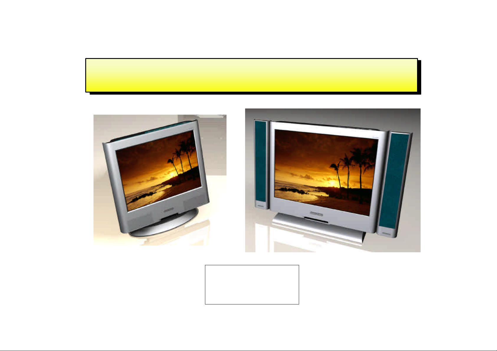
TVL-151M / 201M
TVL-151M
TVL-201M
----------------------------------------------------------------------------------------------------------------------
1

----------------------------------------------------------------------------------------------------------------------
SERVICE MANUAL
TVL-151M / 201M
- Contents -
1. Detail Specification
1-1. PANEL
1-2. IN/OUT JACK
1-3. User Interface Specification
1-4. Electrical Specification
1-5. Available PC Input Mode & Video Timing Standard
1-6. OSD Specification ( America )
1-7. OSD Specification ( *** )
1-8. Factory mode OSD Specification
2. Adjustment Specification
2-1. Adjustment of CLOCK DELAY
2-2. Adjustment of AUTO COLOR GAIN
2-3. Setting Instruction of OPTION
2-4. Adjustment Instruction of VPC3230
3. Inspection Specification
3-1. Inspection of LCD PANEL
3-2. Inspection of INVERTOR
3-3. Inspection of ASSY-CONTROL
3-4. Inspection of ASSY-MAIN
4. Block Diagram
5. Circuit Diagram
6. General Specification
7. Troubleshooting
8. Parts List
9. Main PCB Drawing
----------------------------------------------------------------------------------------------------------
------------
2

SERVICE MANUAL
TVL-151M / 201M
----------------------------------------------------------------------------------------------------------------------
1. Detail Specification
1-1. LCD Panel
▣ LG-Philips LCD Panel : LC151X01-A3 : 15.1"( Panel Link Type )
LC201V1-A3 : 20.1"
1-2. In/Out Jack
▣ Power Supply Input : Din Jack
▣ Antenna Input : 75ohm Unbalanced Din-Jack Type
▣ PC Input : 15pin D-sub Jack ( Female Type )
▣ PC Audio Input : Phone Jack ( Stereo Type )
▣ Composite Video In : RCA Jack
▣ DVD In : RCA Jack (Y, Cb, Cr) - * 20.1" Model Only
▣ S-Video In
▣ Audio Input : RCA Jack ( When Composite or S-Video input )
▣ EURO SCART Jack
▣ Head-Phone Output Jack : Phone Jack ( When the Jack insert, Main Sound is mute. )
▣ Audio Out : RCA Jack ( Monitor Out )
▣ Video Out : RCA Jack ( Monitor Out )
----------------------------------------------------------------------------------------------------------------------
3

SERVICE MANUAL
TVL-151M / 201M
----------------------------------------------------------------------------------------------------------------------
1-3. User Interface
▣ 7 Panel Key
☞ Power , Menu , Select , Vol Up , Vol Down , CH Up , CH Down
▣ 3 Color LED
☞ Red : Stand by Condition
☞ Green : Power On Condition
☞ Scarlet : SLEEP TIME On Condition
☞ Green Blink : When the PC Mode, Inserted D-sub Jack but
H,V Sync is not input or PC Power Save Mode
▣ Remocon Receiver
☞ Remocon ( Pal ; 41Key, NTSC ; 29Key )
▣ On Screen Display
☞ Control using OSD
☞ OSD Language : English, German, Italian etc.
▣ Plug & Play : DDC - 1/2B
▣ Factory Mode
☞ Mode for controlling the adjustment item & Panel Option in mass production
----------------------------------------------------------------------------------------------------------------------
4

SERVICE MANUAL
TVL-151M / 201M
----------------------------------------------------------------------------------------------------------------------
1-4. Electrical Specification
▣ TV Color Standard : PAL,SECAM ( NTSC System : NTSC )
▣ TV Sound Standard : B/G,I,D/K ( NTSC System : M )
▣ TV Stereo Sound : NICAM Stereo , A2 Stereo ( NTSC System : BTSC )
▣ TV Receiving Range : VHF LOW( 2 ~ H ), VHF-HIGH( I ~ W+26 ),
UHF (W+27~78)
Total 100CH ( NTSC System : 181CH )
▣ Sound Output : RMS 1.5W X 2CH
▣ Power Supply : AC / DC Adaptor ( DC12V , 5A , 50 /60 HZ )
☞ Input Power : AC 100V ~ 265V
☞ Power Consumption : Stand-by : 3W , Power On : 45W
▣ Video Input Level : 1 Vp_p , 75 ohm
▣ Audio Input Level : 500mVrms
▣ PC Input Level : Analog RGB Input ( H,V Separator )
☞ See 1-5. Available PC Input Mode & Video Timing Standard.
▣ Audio Output Level : 500mVrms
▣ Head-Phone Output Level : 100mW
----------------------------------------------------------------------------------------------------------------------
5
SERVICE MANUAL
TVL-151M / 201M
----------------------------------------------------------------------------------------------------------------------
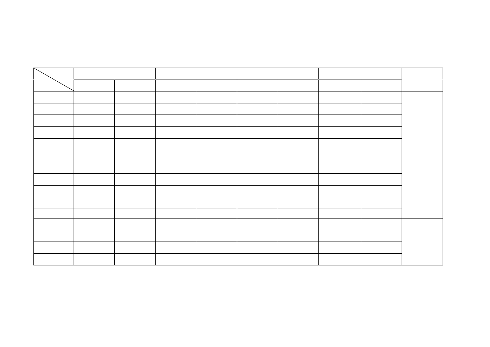
1-5. Available PC Input Mode & Video Timing Standard
Resolution Horizontal Vertical Clock Time
H V ( KHz ) Pol. ( Hz ) Pol. ( MHz ) ( nsec )
IBM 640 350 31.469 P 70.087 N 25.175 39.722
IBM 640 480 31.469 N 59.940 N 25.175 39.722
VESA 640 480 37.861 N 72.809 N 31.500 31.746
VESA 640 480 37.500 N 75.000 N 31.500 31.746
VESA 640 480 43.269 N 85.008 N 36.000 27.778
IBM 720 400 31.465 N 70.087 P 28.322 35.308
VESA 800 600 31.156 N/P 56.250 N/P 36.000 27.778
VESA 800 600 37.879 P 60.317 P 40.000 25.000
VESA 800 600 48.077 P 72.188 P 50.000 20.000
VESA 800 600 48.875 P 75.000 P 49.500 20.202
VESA 800 600 53.674 P 85.061 P 56.250 17.778
VESA 1024 768 48.363 N 60.004 N 65.000 15.358
VESA 1024 768 56.476 N 70.069 N 75.000 13.333
VESA 1024 768 60.023 P 75.029 P 78.750 12.698
Remarks
VGA
SVGA
XGA
VESA 1024 768 68.677 P 84.997 P 94.500 10.582
----------------------------------------------------------------------------------------------------------------------
6

SERVICE MANUAL
TVL-151M / 201M
----------------------------------------------------------------------------------------------------------------------
1-6. OSD Specification
▣ PICTURE
◎ CONTRAST
◎ BRIGHTNESS
◎ COLOR TEMPERAT ( PC input mode only )
※ STANDARD , 6500K , USER, RESET , 9300K
◎ SHARPNESS ( Not Available PC MODE )
◎ COLOR ( Not Available PC MODE )
◎ TINT ( NTSC System Only )
▣ SOUND
◎ BASS
◎ TREBLE
◎ BALANCE
◎ MTS ( S.MODE )
▣ GEOMETRY ( PC input mode only )
◎ H-POSITION
◎ V-POSITION
◎ AUTO POSITION
----------------------------------------------------------------------------------------------------------------------
7

SERVICE MANUAL
TVL-151M / 201M
----------------------------------------------------------------------------------------------------------------------
▣ FUNCTION
◎ TRACKING ( PC input mode only )
※ AUTO TRACKING
※ CLOCK
※ PHASE
◎ INFORMATION
◎ TUNING ( TV input mode only )
※ SORT
※ AUTO TUNING
※ MANUAL TUNING
※ FINE TUNING
※ CH SKIP
◎ LANGUAGE ( PAL/SECAM System )
◎ CAPTION ( NTSC System )
◎ V-CHIP ( NTSC System )
----------------------------------------------------------------------------------------------------------------------
8

----------------------------------------------------------------------------------------------------------------------
SERVICE MANUAL
TVL-151M / 201M
1-8. Factory Mode OSD Specification
▣ How to use Factory Mode
◎ Press Power & Select Key in Panel Control key, and go to Factory mode.
▣ Factory ADJ
◎ CLOCK DELAY
◎ AUTO COLOR GAIN
◎ OPTION
◎ TTX LOCAL
◎ TTX E/W
▣ MX88L281 1
▣ AD9884 1 ( PC input mode only )
▣ AD9884 2 ( PC input mode only )
◎ SUB C VCP
◎ SUB C CHG CURRENT
◎ INIT VCO CURRENT
▣ VPC3230 ( excluding PC MODE )
◎ CONTRAST
◎ BRIGHTNESS
◎ PEAKING
◎ CIP CONTRAST
◎ CIP BRIGHT
** In mass production, adjust only Factory ADJ item, do not adjust other Modes.
( In the time of variation of A/S & initial condition of screen quality , built in other Modes for controlling )
----------------------------------------------------------------------------------------------------------------------
9

SERVICE MANUAL
TVL-151M / 201M
----------------------------------------------------------------------------------------------------------------------
2. Adjustment Instruction ( Factory ADJ )
2-1. Adjustment instruction of CLOCK DELAY
1. Adjustment item : Adjust the dispersion happening in the time of matching ASSY-MAIN and LCD PANEL .
(As the contact status of the CONNCETOR for connecting LCD PANEL, dispersion happens )
2. Adjustment Process : After assembling the SET , do the adjustment.
3. Preliminary adjustment :
1) Connect the outlet VIDEO PATTERN GENERATOR ( ANALOG RGB & SEPARATE H,V OUT ) to INPUT
( 15PIN D-sub with VGA CABLE )
2) TEST PATTERN: 1DOT BLACK, Select WHITE PATTERN.
( In the case of the tool of MSPG-925L, select PATTERN NO.28 )
3) Select Output FORMAT into 1024 x 768 @85HZ. (Select MODEL : 21)
4) Turn on the SET, and them select in PC MODE.
4. Adjustment Instruction :
1) Press SEL & Power Key in Front panel at the same time , go to Factory mode
2) Select CLOCK DELAY ( including in FACTORY ADJ MENU ) with CH UP/DOWN KEY in Factory mode
3) Changing the level of CLOCK DELAY with VOL UP/DOWN KEY, adjust to the noiseless level in screen
( variable range : 0 ~ 15, DEFAULT : 15 )
----------------------------------------------------------------------------------------------------------------------
10

SERVICE MANUAL
TVL-151M / 201M
----------------------------------------------------------------------------------------------------------------------
2-2. Adjustment Instruction of AUTO COLOR GAIN
1. Adjustment Item : Function of automatically setting ADC LEVEL of AD9884 with ANALOG RGB ( D-sub ) signal .
( WHITE BALANCE & CONTRAST adjustment )
2. Adjustment Process : After assembling the SET , do the adjustment .
3. Preliminary Adjustment
: 1) Connect Outlet of VIDEO PATTERN GENERATOR to the input terminal of CVBS.
2) TEST PATTERN : Select COLOR BAR PATTERN
3) Turn on the SET, and then select in VIDEO MODE.
4. Adjustment Instruction
: 1) Press SEL & Power Key in Front Panel at the same time, and go to Factory mode.
2) In Factory mode, select Auto Color Gain in Factory ADJ.
3) Press VOL UP KEY , and then displaying the phrase " Processing " , AUTO Adjustment start
4) When adjustment is completed , the phrase " Processing " disappears
=> caution : In the course of Processing, do not remove the signal.
----------------------------------------------------------------------------------------------------------------------
11

SERVICE MANUAL
TVL-151M / 201M
----------------------------------------------------------------------------------------------------------------------
2-3. Setting Instruction for OPTION
1. OPTION : - X2 - BYPASS
=> Using 6 BIT PANEL
=> Back-Light Control of Inverter
( Bright Max : LOW , Min : HIGH )
2. OPTION : - X2 - INVERT
=> Using 6 BIT PANEL
=> Back-Light Control of Inverter voltage polarity
( Bright Max : HIGH , Min : LOW )
3. OPTION : - X3 - BYPASS
=> Using 8 BIT PANEL
=> Back-Light Control of Inverter voltage polarity
( Bright Max : LOW , Min : HIGH )
4. OPTION : - X3 - INVERT
=> Using 8 BIT PANEL
=> Back-Light Control of Inverter voltage polarity
( Bright Max : HIGH , Min : LOW )
※
Select no 4 in the case that no 4 is not selected .
----------------------------------------------------------------------------------------------------------------------
12

SERVICE MANUAL
TVL-151M / 201M
----------------------------------------------------------------------------------------------------------------------
2-4. Adjustment Instruction of VPC3230
1. Adjustment item : Function of adjusting DEFAULT VALUE of VPC3230 DEVICE.
2. Adjustment process : After assembling the SET, do the adjustment .
3. Preliminary adjustment
: 1) Connect Outlet of VIDEO PATTERN GENERATOR to the input terminal of CVBS.
2) TEST PATTERN : Select COLOR BAR PATTERN
3) Turn on the SET, and then select in VIDEO MODE.
4. Adjustment Instruction
: 1) Press SEL & Powe r Key in Front Panel at the same time , and go to Factory mode.
2) Select VPC3230 in Factory mode.
3) Adjust to the following levels with VOLUME UP/DOWN, CH UP/DOWN
- CONTRAST 52
- BRIGHT 9
- PEAKING 0
- CIP CONTRAST 7
- CIP BRIGHT 7
※
No need to adjust when the SET is stable.
----------------------------------------------------------------------------------------------------------------------
13
SERVICE MANUAL
TVL-151M / 201M
----------------------------------------------------------------------------------------------------------------------
3. Inspection Specification
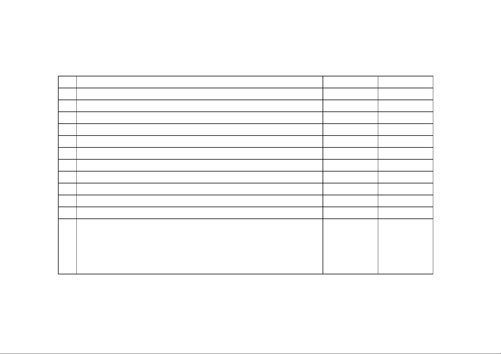
3-1. Input Specification of LCD PANEL ( Total Inspection )
Inspection Procedure Standard Remark
1 Turn off the power of JIG ( check the power of JIG )
2 Connect BACK LIGHT CONNECTOR of LCD PANEL to JIG
3 Connect PANEL Connector of JIG to LCD PANEL
4 Turn on the power of JIG → POWER ON
5 After receiving Black Pattern, check the number of radiant Pixel No the matter
6 After receiving White Pattern, check the number of radiantless Pixel 2 Pixel and less
7 After receiving White Pattern, check the spots No the matter
8 Turn off the power of JIG
9 Disconnect PANEL Connector
10 Disconnect Back Light Connector
1) In order to prevent the spots of PANEL, inspect with Gloves on
RMK
2) In the time of connecting & disconnecting the Connector, surely turn off the power of JIG,
and then go on the inspection.
3) Test Pattern : Full White & Full Black Pattern
----------------------------------------------------------------------------------------------------------------------
14
 Loading...